Study, Design and Implementation of an Application...
94
Study, Design and Implementation of an Application Specific Instruction Set Processor for a Specific DSP Task Master thesis in Electronics Systems at Linköping Institute of Technology by VIVEK PACKIARAJ LiTH-ISY-EX--09/4089--SE Linköping 2008
Transcript of Study, Design and Implementation of an Application...

Study, Design and Implementation of an Application Specific Instruction Set Processor for a Specific DSP Task
Master thesis in Electronics Systems at Linköping Institute of Technology
by
VIVEK PACKIARAJ
LiTH-ISY-EX--09/4089--SE
Linköping 2008


Study, Design and Implementation of an Application Specific Instruction Set Processor for a Specific DSP Task
Master thesis in Electronics Systems at Linköping Institute of Technology
by
VIVEK PACKIARAJ
LiTH-ISY-EX--09/4089--SE
Linköping 2008
Supervisor: Kent Palmkvist ISY, Linköping Universitet.
Examinator: Kent Palmkvist
ISY, Linköping Universitet.
Linköping, 4th November, 2008


Presentation Date 04 – November - 2008 Publishing Date (Electronic version)
Department and Division Department of Electrical Engineering Electronics Systems
Publication Title Study, Design and Implementation of an Application Specific Instruction Set processor for Specific DSP Task Author Vivek Packiaraj
URL, Electronic Version http://www.ep.liu.se
Language X English Other (specify below) Number of Pages 78
ISBN (Licentiate thesis) ISRN LiTH-ISY-EX—09/4089—SE
Title of series (Licentiate thesis) Series number/ISSN (Licentiate thesis)
Type of Publication Licentiate thesis Degree thesis Thesis C-level X Thesis D-level Report Other (specify below)
Abstract There is a lot of literature already available describing well-structured approach for embedded design and implementation of Application Specific Integrated Processor (ASIP) micro processor core. This concept features hardware structured approach for implementation of processor core from minimal instruction set, encoding standards, hardware mapping, and micro architecture design, coding conventions, RTL,verification and burning into a FPGA. The goal is to design an ASIP processor core (Micro architecture design and RTL) which can perform DSP task, e.g., FIR. The report is a well structured approach of design and implementation of an ASIP DSP processor for DSP applications like FIR. This report contains design flow starting from Instruction set design, micro architecture design and RTL implementation of the core. Details of the power simulations of FPGA are also listed and analyzed.
Keywords DSP, Micro-architecture, Processor, RTL, FSM, Instruction set, VHDL, FPGA, Synthesis


Abstract There is a lot of literature already available describing well-structured approach for embedded design and implementation of Application Specific Integrated Processor (ASIP) micro processor core. This concept features hardware structured approach for implementation of processor core from minimal instruction set, encoding standards, hardware mapping, and micro architecture design, coding conventions, RTL,verification and burning into a FPGA. The goal is to design an ASIP processor core (Micro architecture design and RTL) which can perform DSP task, e.g., FIR. The report is a well structured approach of design and implementation of an ASIP DSP processor for DSP applications like FIR. This report contains design flow starting from Instruction set design, micro architecture design and RTL implementation of the core. Details of the power simulations of FPGA are also listed and analyzed.


Acknowledgement This thesis is an outcome of eleven month work starting from specification and ending in an FPGA implementation. Firstly, I wish to show my deep gratitude and thanks to my professor Kent Palmkvist for all the support and guidance. For the last one year, he has always been available and supported all my queries and questions irrespective how big or small it is and motivated me all the time. I heartfully thank my parents, family and friends for motivating me all the time, for all their sacrifice, which is always a great and foremost asset in my life. I am always indebted to them whole my life. I want to express my gratitude to the bank in India for my finances, which sponsored my whole education stay in Sweden.


Table of Contents
1. INTRODUCTION .....................................................................................................................1
1.1. Introduction .........................................................................................................................1 1.2. Chapter Outline ...................................................................................................................3
2. DIGITAL FILTER ALGORITHM
2.1. Advantages .........................................................................................................................5 3. LITERATURE REVIEW
3.1. CPU classifications .............................................................................................................5 3.2. A simple DSP system .........................................................................................................6 3.3. DSP Processor ....................................................................................................................6
3.3.1. Fixed and floating point architectures ......................................................................7 3.3.2. Dynamic range and precision ...................................................................................7
3.4. Applications ........................................................................................................................7 3.5. Bit arithmetic and precision ................................................................................................7
3.5.1. Saturation .................................................................................................................7 3.5.2. Guard........................................................................................................................7 3.5.3. Rounding ..................................................................................................................7 3.5.4. Scaling......................................................................................................................8 3.5.5. Truncation ................................................................................................................8 3.5.6. Top level of the processor ........................................................................................8
4. ASSEMBLY INSTRUCTION SET DESIGN
4.1. Rule of thumb ...................................................................................................................11 4.2. Instruction set design flow ................................................................................................11 4.3. Classification ....................................................................................................................12
5. PIPELINE DESCRIPTION OF THE CORE
..................................................................................................................................................13
6. MICRO ARCHITECTURE DESIGN 6.1. Introduction .......................................................................................................................15 6.2. Data path design ...............................................................................................................15
6.2.1. Register file ............................................................................................................15 6.2.2. ALU .......................................................................................................................17 6.2.3. MAC ......................................................................................................................19
6.3. Address path design ..........................................................................................................21 6.3.1. AGU 0 ....................................................................................................................21 6.3.2. AGU 1 ....................................................................................................................21
6.4. Control path design ...........................................................................................................24 6.4.1. Instruction decoder .................................................................................................24 6.4.2. PCFSM and PC ......................................................................................................25 6.4.3. Loop controller .......................................................................................................27 6.4.4. Hardware stack.......................................................................................................31

6.4.5. Condition logic.......................................................................................................32 6.4.6. Special registers .....................................................................................................33 6.4.7. NOP........................................................................................................................34
6.5. Memory path design .........................................................................................................35 6.5.1. Data path 0 .............................................................................................................35 6.5.2. Data path 1 .............................................................................................................36 6.5.3. Program memory ...................................................................................................36
7. RTL DESCRIPTION OF THE CORE
7.1. Introduction .......................................................................................................................37 7.2. Bus definitions ..................................................................................................................37 7.3. Processor top level RTL schematic ..................................................................................38 7.4. Precision synthesis ............................................................................................................39 7.5. Area info of the cyclone II FPGA .....................................................................................39
8. VERIFICATION AND SIMULATION
8.1. Block level simulation and verification ............................................................................41 8.2. Functional verification ......................................................................................................41 8.3. Testing ..............................................................................................................................41 8.4. Test bench with application ..............................................................................................42
8.4.1. Top level arrangement ...........................................................................................42 8.4.2. Program ..................................................................................................................42 8.4.3. Simulation results...................................................................................................43
9. POWER SIMULATIONS
9.1. Power simulations .............................................................................................................45 9.2. Quartus II- power play power analyzer ............................................................................45 9.3. Results ...............................................................................................................................46
10. CONCLUSION
10.1. Results and future work .........................................................................................49 11. ACRONYM AND ABBREVIATIONS
..................................................................................................................................................51 12. APPENDIX I
12.1. Assembly instruction set manual ...........................................................................53 13. APPENDIX II
13.1. Coding conventions ...............................................................................................73 14. REFERENCES
..................................................................................................................................................77

List of Figures
1. Figure 1: CPU classifications .....................................................................................................5 2. Figure 2: A simple DSP system .................................................................................................6 3. Figure 3: Top level diagram of the processor core ....................................................................8 4. Figure 4: Instruction set design ................................................................................................10 5. Figure 5: Instruction set design flow .......................................................................................11 6. Figure 6: Pipeline diagram .......................................................................................................14 7. Figure 7: Block level schematic of register file .......................................................................16 8. Figure 8: Architectural diagram of the register file .................................................................17 9. Figure 9: Block level diagram of ALU ....................................................................................18 10. Figure 10: Architectural diagram of ALU ...............................................................................19 11. Figure 11: Architectural diagram of MAC unit .......................................................................20 12. Figure 12: ACR low and high architectures ............................................................................21 13. Figure 13: Simplified address generation unit .........................................................................22 14. Figure 14: Address generation AG0 ........................................................................................22 15. Figure 15: Address generation AG1 ........................................................................................23 16. Figure 16: Special read block ..................................................................................................23 17. Figure 17: Block level diagram of the instruction decoder ......................................................24 18. Figure 18: Block level diagram of the PC FSM ......................................................................25 19. Figure 19: Architectural diagram of the PC .............................................................................26 20. Figure 20: FSM diagram ..........................................................................................................26 21. Figure 21: Block level diagram of loop controller ...................................................................28 22. Figure 22: Architectural diagram of loop controller ................................................................29 23. Figure 23: Architectural diagram of loop start registers in LC ................................................30 24. Figure 24: Architectural diagram of loop end registers in LC .................................................30 25. Figure 25: Architectural diagram of special registers in LC ...................................................31 26. Figure 26: Block level diagram of hardware stack ..................................................................31 27. Figure 27: Architectural level diagram of hardware stack .......................................................32 28. Figure 28: Block level diagram of CL .....................................................................................33 29. Figure 29: Block level diagram of special registers .................................................................33 30. Figure 30: Architectural level diagram of special registers .....................................................34 31. Figure 31: NOP multiplexer .....................................................................................................34 32. Figure 32: Block level diagram of data memory 0 ..................................................................35 33. Figure 33: Block level diagram od data memory 1 ..................................................................36 34. Figure 34: Program memory block ..........................................................................................36 35. Figure 35: Hirerchical diagram of processor core ...................................................................37 36. Figure 36: RTL diagram of control path and memory path .....................................................38 37. Figure 37: RTL diagram of data path and address path ...........................................................38 38. Figure 38: Utilization pie chart for EP2C35F672C6 Altera FPGA device .............................40 39. Figure 39:Test bench setup ......................................................................................................42 40. Figure 40: Simulation results 1 ................................................................................................43 41. Figure 41: Simulation results 2 ................................................................................................43 42. Figure 42: Simulation results 3 ................................................................................................44 43. Figure 43: Simulation results 4 ................................................................................................44 44. Figure 44: Flow diagram of power analysis ............................................................................45

45. Figure 45: Power comparision between tow devices for the designed core ............................46 46. Figure 46: graph showing block level power dissipation for EP2C35F672C6 .......................47 47. Figure 47: graph showing clock level power dissipation for EP2C70F672C7 ........................48

List of Tables
1. Table 1: Different pipelining groups and stages ......................................................................13 2. Table 2: Controls signal from diffrent pipeline stages at ID ...................................................24 3. Table 3: Priority in FSM ..........................................................................................................27 4. Table 4: Control signals for LC ...............................................................................................28 5. Table 5: Control signals for LC ...............................................................................................29 6. Table 6: Bus definitions ...........................................................................................................38 7. Table 7: Area report of cyclone II FPGA ................................................................................39 8. Table 8: showing pipeline groups and stages ..........................................................................53 9. Table 9: Instructions supported by core designed ....................................................................54 10. Table 10: Special registers definition ......................................................................................55 11. Table 11: Instruction groups ....................................................................................................55 12. Table 12: Addressing mode defibitions ...................................................................................56 13. Table 13: Showing (ACR 0 and ACR1) ..................................................................................56 14. Table 14: Showing ACR h and ACR l .....................................................................................56 15. Table 15: Showing DM 0 and DM 1 .......................................................................................56 16. Table 16: Flags .........................................................................................................................57 17. Table 17: Scaling .....................................................................................................................57 18. Table 18: Rounding..................................................................................................................57 19. Table 19: Saturation .................................................................................................................58 20. Table 20: Jump conditions .......................................................................................................58 21. Table 21: Load ans tore instructions ........................................................................................59 22. Table 22: Move instructions ....................................................................................................61 23. Table 23: Arithmetic instructions ............................................................................................63 24. Table 24: Program flow instructions........................................................................................67

1
1 Introduction 1.1 Introduction
An Application specific instruction set processor (ASIP) is a component used in System-on-a-Chip (SoC). The instruction set architecture called ISA is designed according to the application which will be running on the processor. This specialization of the core provides a tradeoff between the flexibility of a general purpose CPU and the performance of application specific integrated circuits (ASIC). Some ASIPs have a configurable instruction set.
Usually, these cores are divided into two parts: static logic which defines a minimum ISA and configurable logic which can be used to design new instructions. The configurable logic can be programmed either in the field in a similar fashion to a field programmable gate array (FPGA) or during the chip synthesis. [1]
ASIP DSP is a processor where functions are mapped into subroutine consisting of assembly instructions where in ASIC DSP we map the DSP algorithms to circuit directly. If the DSP function is easy and straight forward, it is always easy to design an ASIC DSP. Two main drawbacks of the ASIC DSP is money and time. However when algorithm or application is complicated, especially when algorithm details cannot be decided during the system design, we cannot use this method. Mapping applications to instruction set is the only solution. The use of an FPGA could cover come both these problems. It is mass-produced and reasonably inexpensive. Any embedded system will have four major parts in it. It may include a DSP subsystem, a memory subsystem, a microcontroller subsystem and I/O units such as sensors, analog circuits and other peripherals. The DSP core developed in this thesis is a digital filter processor (Application Specific Instruction set Processor), which supports the general filter equation. The whole design is based on the Harvard architecture which allows multiple memory reads. Today most of the speech and audio processing is related with auto-correlation, convolution and FIR calculation [2], which is supported by this core. The core also supports any function based on convolution. The core includes data path, address path and control path. The data path consists of an ALU, MAC and RF (register file) while the address path consist of two AGU (address generation units) supporting various addressing modes like modulo, post incremental, decrement, register indirect etc. The control path consists of a Finite State Machine (FSM).
1.2 Chapter Outline
First the author discuss about the literature review and understanding of specific DSP task then instruction set design for the specific task is designed and the encoding methodology is done which is added in the appendix. Then the author briefly discuss about the micro-architecture design of all the blocks and corresponding RTL coding of the design. The coding conventions for

2
the design are also added into the appendix. Then the power simulation is run for the synthesizable design for a specific FPGA target. The coding is done in the VHDL language, Mentor FPGA advantage and Quartus II are used for synthesize and power simulations accordingly.

3
2 Digital Filter Algorithm A digital filter performs mathematical operations on sampled signals to reduce or enhance certain aspects of that signal. The basic operation needed to implement a digital FIR filter is the signed multiply-and-accumulate (MAC), which is traditionally performed using a hardware multiplier peripheral in any DSP device. Some of the devices including our design have an integrated hardware multiplier that can perform this MAC operation allowing these devices to run the FIR filter algorithm more efficiently than devices without a built-in hardware multiplier. The core designed in this thesis is specialized to do the FIR application. The digital filter equation is given below [3]
Y[n] =∑ c[k] × x [n-k] + ∑ d[j] × y[n-j]
k j
Where y[n] is output, x [n-k] is previous input, y [n-j] is previous output and, c[k] and d[j] are coefficients.
2.1 Advantage of Digital Filter
Programmability The digital filter can easily be changed without affecting the circuitry Analog filter circuits are subject to drift and are dependent on temperature Digital filters can handle low frequency signals accurately as the speed of DSP
technology continues to increase, digital filters are being applied to high frequency signals in the RF domain
Versatility Adapt to changes in the characteristics of the signal

4

5
3 Literature Review
3.1 CPU Classification The CPU is the heart of any device which runs the program on it. Here the classification of the CPU is discussed briefly. Generally CPU’s are divided into MPU’s, MPC’s and DSP’s. MPU refers to the general purpose processors like Intel and MPC refers to the micro controller units like ARM and DSP refers to the digital signal processor like TMS320. The DSP is subdivided into VLIW (very large instruction width), superscalar single instruction multiple data DSP and finally ASIP (application specific instruction set processor) which is discussed here elaborately.
Figure 1: CPU classification
3.2 A simple DSP system
Digital signal processing algorithms typically require a large number of mathematical operations to be performed quickly on a set of data. Signals are converted from analog to digital, manipulated digitally, and then converted again to analog form, as diagrammed below. Most DSP applications have a constraint on latency.
CPU
DSP
VLIW
Superscalar
DMAC and SIMD DSP
Low power DSP
ASIP DSP
MPUGeneral purpose
processor
MCU
High end microcontrollers
Low end microcontrollers

6
Most general-purpose microprocessors and operating systems can execute DSP algorithms successfully. But these microprocessors are not suitable for handheld devices like a PDA or low power operations because of strict power consumption and space limit. A specialized digital signal processor, however, will tend to provide a lower-cost solution, with better performance and lower latency. The architecture and micro-architectural work of any digital signal processor is optimized specifically for digital signal processing work.
Figure 2: A simple DSP system
3.3 DSP Processor DSP processors are Programmable microprocessors specialized for applications of digital signal processing algorithms. They are generally characterized by some special functions like:
Separate program and data memories (Harvard architecture) Memory architecture designed for streaming data Algorithm friendly instructions like convolution. Multiply-accumulate units (MAC). Multiple access memory architecture. Specialized addressing modes such as modulo, bit reversed. Hardware loops. Restricted interconnectivity between registers or functional units.
3.3.1 Fixed and floating point DSP Processor In the architecture level fixed point processor is designed for computing a fixed point number representation i.e. which has a fixed number of digits after the radix point or decimal point. This architecture is always cost effective and has a speed benefit due to reduced hardware complexity. On the other hand floating point DSP processor has a wide dynamic range and more precision than the former. Fixed point architectures are more favored where the manufacturing costs are low. Fixed point DSPs continue to benefit more from cost reductions of scale in manufacturing, since they are more often used for high-volume applications; however, the same reductions apply to floating point DSPs when high volume demand for the device appears. Today, cost has increasingly become the issue of SOC integration and volume, rather than the result of the size of the DSP core itself. In a 32 bit DSP processor the mantissa is usually 24 bits: so the precision of a floating point DSP is the same as that of a 24 bit fixed point processor. But floating point has one further advantage
Analog signal
ADC DSP DACAnalog signal

7
over fixed point: because the hardware automatically scales each number to use the full word length of the mantissa, the full precision is maintained even for small numbers [4]
3.3.2 Dynamic range and precision Dynamic range is the range available between the maximum and the minimum value for the number of bits available. For a 16 bit data length processor the dynamic range is 32767. Precision is defined by how precise we can represent a number and the largest number that we can represent is the dynamic range.
3.4 Applications DSP processor are widely used for audio, video applications, speech processing’s, filters, sound cards, digital cameras, cars, fax, medical instruments, machines, modems, cellular phones, high-capacity hard disks and digital TVs. DSPs are used as the engine in 70% of the world's digital cellular phones, and with the increase in wireless applications, this number will only increase according to According to Texas Instruments [14]. Digital signal processing is used in many fields including military, sonar, radar, seismology, speech and music processing, imaging and communications.
3.5 Bit Arithmetic and Definitions
3.5.1 Saturation Saturation in arithmetic is defined by any operation which is limited to a dynamic range i.e. can be only between a minimum to maximum value, if the value of the result goes beyond that then we according to the operation set the maximum positive or maximum negative value that can be represented by the range.
3.5.2 Guard In the multiply and accumulate (MAC) unit, to avoid overflow we add additional bits replicating the sign bit. Usually the length of the guard bits is 6 to 8, 6 in this design.
3.5.3 Rounding This logic is used to round a value, for example if we have a 16 bits and we need to round to 8 bits, test the 9bit, if it is a ‘1’ then add this one to the 8 bit or if it is a ‘0’ just leave the reaming 8 bits. So that the total result from the rounding is 8 bits.

8
3.5.4 Scaling This is a process of scaling the size of the result by a known value. For example the result can be scaled by 2 or 4 or 8 etc.
3.5.5 Truncation It is a process of limiting the number of bits by just discarding the unwanted bits.
3.6 Top level Processor core diagram
Figure 3: Top level processor diagram
CONTROL
PATH
RF ALU MAC
Processor memory (data and address) busses
PM DM 1 DM 2
DM 1 DM 2
Addressing path

9
4 Assembly Instruction Set Design The instruction set architecture (or ISA) is one of the most important design issues that a CPU designer must get right from the start. The instruction set design in the interface of the processor to the end user. The design goals can be driven to a maximum performance subjected to a cost limit or driven to achieve a minimum cost subjected to a maximum performance. The performance of the processor core also depends on the compiler. The author suggests the reader to look into the Instruction set manual attached. Any instruction set can be categorized by the number of operands used in the most complex instruction, which are three in this case. The instructions in the ISA in this design are divided into RISC (reduced instruction set computer) and CISC (complex instruction set computer). The RISC is a four stage pipelined and CICS is 5 stage pipelined. The list of all instructions supported by the core are given in the assemble instruction set manual. The core designed in this thesis is pipelined with 4 stages and a couple of instruction with 5 stage pipeline.
Figure 4: Instruction set design
Instruction Set
Architecture
Application coverage
Requirements and
constraints
Source code profiling

10
4.1 Rule of thumb
This is rule where 90% of the instructions run 10 % of the time and 10 % of the instruction run 90% of the time. So it is important to identify the instruction used most by the algorithm. It really means that 10 % of the instructions are used for the functional coverage and therefore we should optimize that for enhancing the design. [5]
4.2 Instruction set design flow
No
Yes
Figure 5: Instruction set design flow [1]
90% - 10% rule
RISC Instru. design
CISC Instru. design
Other Instru. design
Benchmarking
Satisfied
Manual

11
4.3 Classification In the instruction set design there are four major groups of classification:-
Load Store covers all load store and set instructions. Move covers all move, push and pop. Arithmetic includes add, postop. Conv and dec. Program Flow covers all jumps, call and return instructions.

12

13
5 Pipeline Architecture The overall system speed can be increased by pipelining because the speed of each stage is much faster than the whole processor core and all stages are running in parallel. This processor has a 5 stage pipeline. The processor pipeline below is described according to the processor architecture. The speed of the processor always goes high with deep pipeline stages, but consumes more clock cycles while taking branches. More pipeline stages also require more no of hardware running in parallel. The pipeline diagram of the system is described in table 1 as below. IF, ID, OF, EX, AG means correspondingly instruction fetch, instruction decode, operand fetch, execution and address generation.
Group Sub-division Stage 1 Stage 2 Stage 3 Stage 4 Stage 5
RISC
Others IF ID OF EX
memory-Store IF ID AG/OF Store
CISC
memory-Load IF ID AG/OF Load EX
Convolution IF ID AG OF EX
Table 1: showing different pipelining group and stages
In the following text, the typical pipeline stages are described in the micro architecture level: Stage 1: IF (Instruction Fetch) In this stage an instruction is fetched from the program memory by using the PC value as the memory address. (For all groups) Stage2: ID (Instruction Decoding) This is a stage where the fetched instruction is decoded. This may be or may not be clocked. (For all groups) Stage3: OF (Operand Fetch) or AG (Address Generation) Operands can be fetched either from the register file or the data memory. This stage is used for operand fetch by some instructions and address generation by some other. Stage 4: Execution of the instruction takes places in this stage. Normally all operation takes one clock cycle, while the MAC operation takes 2 or more clock cycles, one for the multiplication and second clock cycle is for accumulation. Stage 5: This stage exists for only for the CICS instructions. The instructions are executed from the operands which were fetched from the data memories during the previous stage.
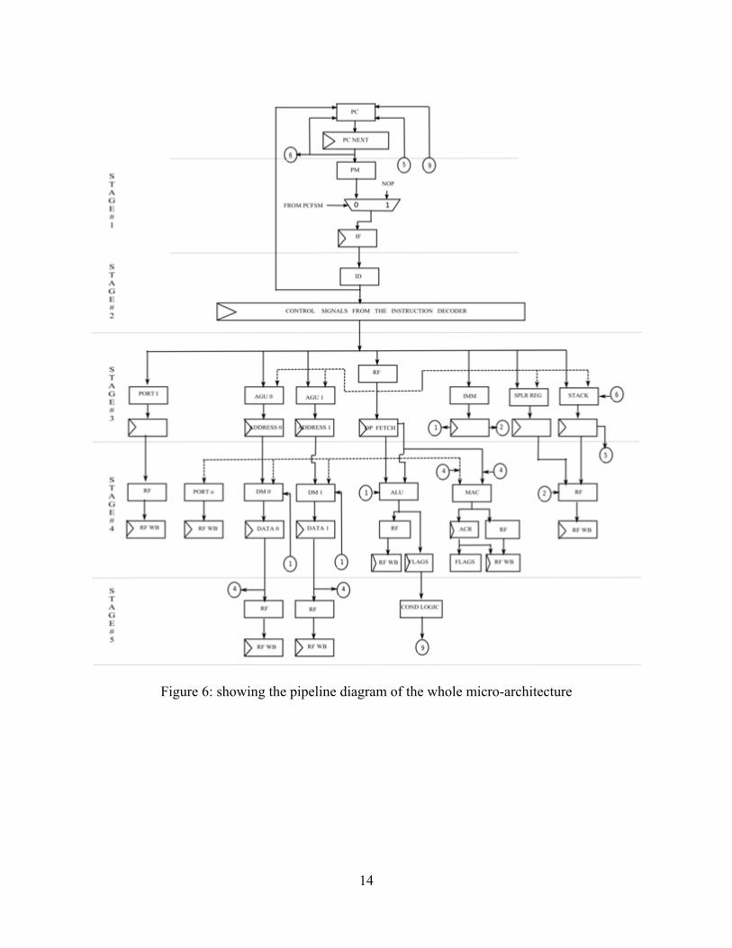
14
Figure 6: showing the pipeline diagram of the whole micro-architecture

15
6 Micro-Architecture design
6.1 Introduction Micro architecture design is a process of implementing assembly instruction set with physical implementation constraints such as performance, power and cost. Generally the architecture design does not involve the specification of the hardware in detail whereas the micro architecture design includes all the hardware design details. The total hardware is reduced by thorough hardware multiplexing.
6.2 Data path design
6.2.1 Register File The register file size is decided in the assembly instruction set design. In this case it is 16. The size should be carefully chosen because too many registers in the file would give high silicon cost and too small would cause too much data swapping between them. The register file is a set of 16 general purpose registers multiplexed to operand A and operand B. In this circuit, only one write per the clock cycle is allowed and the register file can supply two operands, A and B at the same time. Four bits are required to select one out of 16 registers. Note that the opa_i and opb_i is not used since there is no instruction for moving data between general registers but we can use them if we add an instruction that does this operation. It is optional.

16
Figure 7: showing the block level schematic of a register file dec_rf_datamux_sel is the control signal from the instruction decoder that selects which of the sixteen registers to write/read to. Here a 4 bit control signal is used to select one of the 16 registers from the first register to the last register. If dec_rf_datamux_sel is 0001 the write would be performed on the first register reg1. For read operation, the corresponding register would be connected to the output opa_o and opb_o depending on the control signals dec_rf_opa_sel and dec_rf_opb_sel, both are 4 bit signals from the instruction decoder.
RF
opa_o
opb_o
opa_i (optional)
dm0data_i
clk
rst
opb_i (optional)
dm1data_i
immediatedata_i
portidata_i
macdata_i
splrddata_i
stackdata_i
aludata_i
dec_rf_opa_sel
dec_rf_opb_sel
dec_rf_enable_sel
dec_rf_datamux_sel

17
Figure 8: showing the architectural level schematic of a register file The above diagram shows the micro architecture diagram of a register file with 16 register of 16 bits each. The mux in the figure 2a is called the data selection mux which selects between ALU, RF, and MAC etc. Both the outputs opa_o and opb_o are again connected back to the data mux. It is very important to know that the register file consumes significant gate count in a DSP core.
6.2.2 Arithmetic Logic Unit (ALU) The data path hardware also includes an ALU. ALU stands for arithmetic and logic unit. In this processor core the ALU is a very small part since it is more application specific, but in general purpose designs the ALU could cover more functions like shift, rotation and bit manipulation functions. ALU only executes RISC instructions, all operands to the ALU are from the RF. The execution cost of ALU is one clock cycle. In early days the ALU was a part of MAC in some design because of the large silicon cost but now since the silicon cost become drastically reduced we can have this hardware separated so that we attain high parallelism.
Dec_rf_datamux_sel
opa_o
opb_o
......
reg0
reg1
reg14
reg15
dec_rf_enable_sel
dec_rf_opb_sel
from RF
from data memory 0
from data memory 1
from ALU
from MAC
from control path
from external IO
1 0
1 0
1 0
1 0
dec_rf_opa_sel

18
Figure 9: showing the block level schematic of an Arithmetic Logic Unit The implementation methodology for the ALU unit is just to collect the instructions running in the module, all micro operations and design it accordingly. After the design of the entire hardware module individually we can reduce the whole hardware by hardware multiplexing. Let’s trace all the instructions in the instruction set architecture which would be running in the ALU module. They are:
ADD Ra Rb DEC Rd CMP rd, # IMM
In the architectural schematic of the ALU, there are two muxes and two control signals to control them. The first one is Dec_alu_sel1 which comes from the decoder which is a 2bit control and the second one is a one bit control called Alu_sel2_i.
The pseudo code for the Alu_sel2_i is given by If Dec_alu_sel1 <= ‘1’ then Alu_sel2_i <= MSB (Dec_alu_sel1) Else ‘0’
flags_o
ALU
opa_i
opb_i
clk
rst
immediatedata_i
alu out_o
dec_alu_mux1_sel
-1

19
Figure 10: showing the architectural level schematic of an Arithmetic Logic unit
6.2.3 Multiply and Accumulate Unit (MAC) This is the most important hardware of the processor core and it remains the same in the data path of any DSP processor. The design of MAC depends on the designer; it can be designed differently for the same instruction set. The convolution is the most important used kernel algorithm. The MAC consists of a one multiplier unit and one accumulator unit. The MAC unit in this processor core can perform Signed / Unsigned, Integer / Fractional according to the programmer. 8 guard bits are introduced to protect from overflow but only 6 are added because 2 sign bits are already included for both operands. Most General purpose processors have 6 guard bits. The multiplier used is a 17 * 17 bit multiplier including the sign bit of both operand. The MAC unit also has scaling options 2, 0.5 and 0.25. The 16 bit left shift is not included in the scaling because it is a hidden operation which is useful when lower parts of the accumulator are multiplied. This 16 bit left shift is to transfer the content from lower part to the higher part. The unit also has round and saturation logic. The MAC unit needs to accommodate the following instructions like:
+
00 10 11
Flags
opa_i opb_i immediatedata_i ‘-1‘
aluout_o flags_o
dec_alu_mux1_sel
MSB of dec_alu_mux1_sel

20
Move accumulator (0 /1- H/L) contents to general register, move accumulator 0/1 contents to general register, move content of general register to accumulator (0/1- H/L), MAC, adding two accumulators 0 and 1 and clear ACR 0/1, where ACR are accumulator registers. For signed multiplication the MSB is copied as the sign bit, which is before the MSB. For unsigned multiplication the sign bit is assumed as ‘0’. F is a control signal from the decoder which tells the multiplication weather the operands are fractional or integer. For Integer it is {6’b [33], [33:0]} and for Fractional it is {6’b [32], [32:0], 0} because for fractional multiplication, there should be one logical left shift. The MAC unit has only one flag which is a Mac overflow flag which checks for overflow.
Figure 11: showing the Architectural level schematic of a multiply and accumulate unit In this processor core, as per the instruction set manual we have 2 accumulator registers ACR 0 and ACR 1 which are 40 bits. Load guard_i is a signal for filling 8 guard bits if a content of general register is moved into the higher part of the accumulator (Fill guard bits to [39:32]. And the top level diagram of the accumulator is given by:
1 0
RND
+
0 1
MAC Flags SAT
‘0‘ or ‘1‘
00 10 01
A C R 1 L
A C R 1 H
A C R 0 L
A C R 0 H
17 * 17 Multiplier
0 1 0 1
Signed /Unsigned Signed /Unsigned
Integer /Fractional
Gaurd ‘6‘
00 01 10 11
000 001 010 011 100
<<16 0.25 0.5 2
0 1
‘0‘
To RF Otput to Flags
Dec_mac_sel 1 Dec_mac_sel 2
Dec_mac_sel 3
Dec_mac_sel 4
Dec_mac_sel 5
Dec_mac_sel 6
Dec_mac_sel 7
Dec_mac_sel 8
Dec_mac_sel 9
Dec_mac_sel 10 Dec_mac_sel 11
Dec_mac_sel 12 Dec_mac_sel 13
F
U1 U2
0 1
DM 0 Ra (Opa) Dm 1 Rb (Opb)
40 bits
‘0‘
00 11 01 10 00 11 01 10 00 11 01 10 00 11 01 10
’0’ ’0’ ’0’ ’0’

21
Figure 12: showing the ACR low and ACR high micro-architecture
6.3 Address path design
6.3.1 Address generation unit (AGU 0 and AGU 1) The ASIP core has a dedicated address generation unit for each memory. So totally 2 AGU are designed. Both the address generating unit AG0 and AG1 supports bit reversal mode, modulo addressing mode and variable step mode. Please refer the assembly instruction set manual for the specifications of different addressing mode supported by the core. Only one adder is used for each address calculation logic. So that the cost is minimized and we use hardware multiplexing for selecting different addressing modes. The width of the address bus is 16 to cover a memory address of 216 = (0 – 65536). A simplified addressing unit is given below, the initial address is to initialize the addressing algorithm for iterative computing, and the keeper keeps the old address for iterative computing. The address pointer is connected to the memory. This unit has a single address pointer, where multiple address pointers can also be designed. Multiple address pointers are designed for fetching multiple operands and to reduce the addressing cost. For example if we need two operand simultaneously from the memory, we need two addressing logic circuits. The blocks which are inside the dotted box of the figure AG 0 and AG 1. I.e., this is the address pointer, though it is a part of the address generation unit, we add this part in the beginning of the data memories so that we don’t miss the timings when we synthesize into a FPGA. The address calculation logic in the figure 5a is shown in 5b. This performs the effective address calculation
A C R 0/1 L
Clk
Reset
Data_i
Clk
Reset
Data_i
Loadguard_i
Data_o [ 39 : 0]
A C R 0/1 H
[ 39 : 16 ]
[ 15 : 0 ]

22
logic which the processor core need. To make the address generation unit and loop counter 4 cycles we deploy a special read/write block so that the design becomes simpler.
Figure 13: showing a simplified addressing unit 00
00
3 41 2
00 01 10 11
dec_ag0_sel_ 4
To Special read block
000 001 010 011 100
Address to DM 0
0 1
add. pointer
dec_ag0_sel_ 9 (from ID)
16 bits
1
2
STEP 0
AG 0
+
‘0‘ 0r ‘1‘
#IMM
opa_i
00 01 10dec_ag0_sel_ 1
dec_ag0_sel_ 5
00 01 10
00 01 10
=
4
3
Bit Reverse
BOT 0
TOP 0
0 1
0110
0110
dec_ag0_sel_ 2
dec_ag0_sel _3
dec_ag0_sel_ 6
dec_ag0_sel_ 7
step_0_value_iopa_i
opa_i ag_0_value_i
opa_itop_0_value_i
bot_0_value_i opa_i
11
101
opb_i
10 11
opb_i
Figure 14: showing address generation AG0
Address Calculation Logic
Initial Keeper
Address pointer
Combinational
Registered output
Input
Addressing feedback

23
Figure 15: showing address generation AG1
Figure 16: showing Special read block
The special address block is to make the AG 0, AG 1 and LC, shown as no. 3, connected to a special read block. The special read block is shown with a curly bracket with no. 1, which takes one clock cycle more.
3 41 2
00 01 10 11
dec_ag1_sel_ 4
000 001 010 011 100
Address to DM 1
0 1
add. pointer
dec_ag1_sel_ 9 (from ID)
16 bits
1
2
STEP 1
AG 1
+
‘0‘ 0r ‘1‘
#IMM
opa_i
00 01 10dec_ag1_sel_ 1
00 01 10
=
4
3
Bit Reverse
BOT 1
TOP 1
0 1
000110
000110
dec_ag1_sel_ 2
dec_ag1_sel _3
dec_ag1_sel_ 6
dec_ag1_sel_ 7
dec_ag1_sel_ 500 01 10
step_1_value_iopa_i
opa_i ag_1_value_i
opa_itop_1_value_i
bot_1_value_i opa_i
11
opb_i
101
opb_i
Special read_o
Spl read block
11
AG 0 AG 1 LC
Special read/write
3
1
dec_sprreg_sel 00 01 10
Register File (RF)

24
6.4 Control path design
6.4.1 Instruction Decoder (ID) The instruction decoder is a very important part of the control path and it outputs a clocked control signals for each and every block in the core. The main advantage of instruction decoder is that it does not have any design rules to be followed other than the functional part. The instruction from the program memory is converted to control bits based on the operation and operands.
Figure 17: showing the block level diagram of an ID Control signal_1 controls for PC FSM, LC, AGU, immediate value, stack rd., port I and operand fetch for MAC, ALU, Data memories 0/1, Port o, and Stack wr. Control signal_2 controls for data memories 0/1, port o, ALU, stack wr, Special register, RF for stack rd, ALU, MAC (including accumulators), and conditional logic. Control signal_3 controls for RF (for data memories 0/1), MAC ( convolution operation)
Table 2: showing control signal outputs at different stages of ID
Instruction decode logic
Pipeline Logic
Clk Pm instr i
Control signals 1 Control signals 2 Control signals 3

25
6.4.2 PC and PC FSM The control path of any processor must have three necessary parts, the program memory, program flow controller, and the instruction decoder. The PC FSM is nothing but the state machine inside a program flow controller. The PC FSM points the address of the next instruction to be fetched from the program memory. The default state is PC<=PC+1. Conditions of the PC FSM as per the priority are shown below in the table 3: The overall block diagram of a PC FSM is shown below followed by the architectural diagram of the PC and the state machine diagram of the FSM. The PC is nothing but a pointer which shows the address of the program memory.
Figure 18: showing Block level diagram of PC FSM
pc_address_o (To PM)
lc_pcfsm_flag_o (Loop Flag)
PC FSM
dec_pc_loops_i (PC + N = Loop end) pcfsm_lc_mux_sel1_o (Mux control for loop register)
clk
rst
reapeat_i
condlogic_fsm_ctrl
PC
PC register
clk
rst
stackdata_i
immediatedata_i
dec_pc_loops_i (Loop start address)
pcfsm_pc_mux1_sel (from FSM) pcfsm_pc_mux2_sel
pc_address_i (PC value)
pc_address_i (PC value)
reset_address_i
pcfsm_nop_sel (Mux control for nop)
dec_pcfsm_jump_ctrl
dec_jumpcallreturn_ctrl
pcfsm_stack_mux2_sel_o

26
Figure 19: showing the architectural level diagram of PC
Figure 20: showing the FSM diagram
pc_address_o (PM)
1
+
stackdata_i
immediatedata_i
dec_pc_loops_i
PC
000
001
010
011
100
pcfsm_pc_mux2_sel
-1
0
1
pcfsm_pc_mux1_sel
clk
rst
reset_address_i <= (others => 0);

27
The transition of the state’s only depends upon the clock and reset value. In the FSM diagram 8c, whenever there is a reset signal the state machine comes to the default state s0. The reset signal is handled in the program counter where if reset = ‘1’ then the program counter simply takes the value of the reset address which is shown in the figure 8b. The dec_jumpcallreturn_ctrl is a one bit control signal from the decoder. Whenever the decoder decodes a conditional jump or unconditional jump or call or return this will be a ‘1’ else ‘0’. This control signal is used in the finite state machine from going to the s1 state from the default state (s0). The jump, call and return instructions are handled in state S3 by a 2 bit control signal dec_pcfsm_jump_ctrl from the decoder and we classify them accordingly If dec_pcfsm_jump_ctrl is “00” it is a call instruction If dec_pcfsm_jump_ctrl is “01” it is a return instruction If dec_pcfsm_jump_ctrl is “10” it is a unconditional jump and If dec_pcfsm_jump_ctrl is “11” it is a conditional jump For the conditional jump the condlogic_fsm_ctrl is also checked and for the unconditional jump instruction this control signal from the conditional logic is assumed as true since there are no conditions. The tabular column shows the priority level of the finite state machine and it is well known that the default state has the least priority.
Next PC Decision priority Condition
PC<=0 Highest Reset and hold on reset PC<=Interrupt or exception 2nd (Not implemented in ) PC<= jump target address 3rd Call or Jump taken
PC<= Stack pop 4th Return from a call PC<=PC 5th To a loop and in a loop
PC<=PC+1 lowest Default
Table 3: showing the priority in the PC FSM
6.4.3 Loop Controller (LC) A hardware loop is a hardware circuit developed for execution of iterative algorithm in a DSP processor. N in the loop controller represents the number of iterations. The loop controller is a sub module in the program flow controller of the processor core. The loop controller usually counts down while running the loop instruction. The loop controller which we designed will also support the REPEAT instruction (M instructions, N times). This loop controller does not support nested hardware loops. There is also a special case where N=1, repeat M instructions 1 time. This is a very special case since we store the value of (N-1) in the N register. This special case is handled by the instruction decoder where if it is a Repeat instruction and N=1 then we don’t need to inform the PC FSM else if repeat= 1 and N ≠ 1, then we could inform the PC FSM with a control signal. To support this we need an additional circuit. The nested loops can be achieved

28
by a software loop using a jump instruction. When the loop controller counts ‘0’, the zero flag is set and is sent to the PCFSM. The main block level architecture of a loop controller is shown below:
Figure 21: showing Block level diagram of loop controller (LC) From the block level architecture, the main input/output signals are shown. Further subdividing the signals as illustrated below:-
Block
Signals in the design Purpose Identification
Instruction Decoder
dec_lc_loopn_i N Value A dec_lc_mux2_sel ctrl signal to store N A dec_lc_loops_i loop start address B
dec_lc_loops_sel ctrl signal to store S B dec_lc_loope_i loop end address C
dec_lc_loope_sel ctrl signal to store E C dec_lc_loopnse_sel ctrl for the splr data out D
PCFSM pcfsm_lc_mux1_sel to decrement N A OUT loop_splrdata_o splr. Data out D
lc_pcfsm_flag_o flag of LC A
Table 4: showing control signals for LC
dec_lc_mux2_sel (from ID)
dec_lc_loops_sel (from ID)
dec_lc_loope_sel (from ID)
LC
dec_lc_loopnse_sel (ID)
pcfsm_lc_mux1_sel (from FSM)
dec_lc_loopn_i (Loop N)
dec_lc_loops_i (PC value)
loop_splrdata_o (Special data)
l c_pcfsm_flag_o (Loop Flag)
clk
rst
dec_lc_loope_i (PC value + N)

29
Figure 22: showing the architectural level diagram of a loop controller (LC) The control signal of the loop controller (LC) diagram – A are described below
pcfsm_lc_mux1_sel (from FSM)
dec_lc_mux2_sel (from ID) Operation
0 00 Keep the previous value 0 01 Load the value to Loop N 0 10 Load the value to opa_i 1 00 Decrement the value by ‘1’ 1 01 Load the value to Loop N 1 10 Load the value to opa_i
Table 5: showing control signals for LC
dec_lc_mux2_sel (from ID)
+
0
1
00
01
Loop N OR
lc_pcfsm_flag_o (Loop Flag)
dec_lc_loopn_i (Loop N)
pcfsm_lc_mux1_sel (from FSM)
‘- 1‘
loopn_o
10 opa_i

30
Figure 23: showing architectural level diagram of loop start registers in LC
Figure 24: showing architectural level diagram of loop end registers in LC
loope_o
10 00
Loop E
dec_lc_loope_i
dec_lc_loope_sel (from ID)
01
opa_i
11
PC + P, end address for repeat
10 00
Loop S
dec_lc_loops_i
dec_lc_loops_sel (from ID )
loops_o
01
opa_i
11
PC start address for repeat

31
Figure 25: showing architecture level diagram of Special registers in LC
6.4.4 PC Stack The pc stack is used to support interrupt and procedure calls. This is nothing but a First in First out (FIFO) buffer with a depth of 8. The decoder signal dec_stack_mux1_sel is used to decide what should be written to the stack. The control signal from the FSM, pcfsm_stack_mux2_sel is for incrementing the stack pointer values on push and call and decrementing the stack pointer value on pop and return. Only PC should be pushed into the stack when there is a procedure call and PC should be popped out when there is a return.
Figure 26: showing block level diagram of stack
clk
rst
dec_stack_mux1_sel
opa_i
pc_address_i
stackdata_o Stack
pcfsm_stack_mux2_sel
dec_pcstack_wren_ctrl
dec_pcstack_rden_ctrl
dec_lc_loopnse_sel 00 01 10
loop_splrdata_o (Special Data)
loopn_o (No. of iteration N)
loops_o (Start address)
loope_o (End address)

32
Push and pop means pushing a register to stack and popping a stack to register. The stack pointer is 4 bit where we take the last 3 bits to select which register value to read or write to.
Figure 27: showing the architectural diagram of a PC stack
6.4.5 Condition Logic (CL) The condition logic is used for testing our flags (MAC flags and ALU flags) and gives an output condition_logic_0 to the pcfsm. In the assembly instruction set manual there is only one instruction which needs a condition in the processor core which is JUMP NE K, which means that it would jump to the given address K if the previous instruction result is not equal to zero. If the previous instruction was a compare and it does equals to zero then the pc value is incremented by one. The signal dec_condition_jump_ctrl_i is a 2 bit control signal from the decoder, which informs the PC FSM weather it is a jump, call or return instruction. For JUMP NE K it is a 11 and for unconditional JUMP it is 00. When this is “11” the condition logic checks for the ALU zero flag alone and if its 00 then it sets a cond_logic_fsm_o to ‘1’ else ‘0’. The output signal goes to the PC FSM which decides jump or not to.
.
.
0 0 0 1 1 0
+1 -1
0 1
+
This is on Reset ‘ 0 ‘
5 bit stack pointer
stack_mux3_sel pseudo code : if rst = 1 then Sel = 00 elsif push or pop instr sel = 01 else sel = 10
pcfsm_stack_mux2_sel
dec_stack_mux1_sel
pc_address_i
opa_i
4 bit stack pointer [ 3 to 0 ]
register1_mux1_sel
stack_register1
stack_register2
stack_register2
stack_register8
0001
0010
0011
1000
.
.
0 1 1
0
1 0
1 0
1 0
register2_mux2_sel
register3_mux3_se3
register8_mux8_sel

33
Figure 28: showing the block level diagram of a CL
6.4.6 Special Registers As per the assembly instruction set manual there are totally 16 special purpose registers (SR0 to SR15). All these registers have the same block level architecture in common. Spr_addr_i is the address of the special register from the instruction decoder and Spr_data_i is the special data to be written or read. Spr_data_wren is a control signal from the instruction decoder which chooses between write or to read. If its low then the input is presented in the output else the corresponding special register is updated with the new value.
Figure 29: showing the block level diagram of a special register
Spr_data_o Spcial Register
Clk
Reset
Spr_data_i
Spr_data_wren
Spr_addr_i
dec_condition_jump_ctrl
ALU flags
MAC flags
condlogic_fsm_ctrl_o C L

34
According the multiplexer control signal Dc_sprreg_sel the special register is written to the register file (RF) according the below block diagram
Figure 30: showing the block level diagram of a special registers
6.4.7 No operation (NOP) This block is to introduce a NOP instruction automatically. The architecture is shown below. For example, in the REPEAT instruction there is a special case where N instructions can be repeat 1 time. While this happens we need an extra cycle to load the special register so a NOP is introduced automatically from the control signal pcfsm_nop_sel from the FSM. For others the control signal is set to ‘0’ where the instructions from the program memory are given in the output.
Figure 31: showing the block level diagram of a NOP multiplier
0 1
pm_instruction_i NOP
pm_instruction_o
pcfsm_nop_sel
AG 0 AG 1 LC
Special read/write
3 clock cycles
1 clock cycle
Dc sprreg se
00 01 10
Register File (RF)

35
6.5 Memory path design
6.5.1 Data Memory 0/1 The two data memories are single port synchronous static random access memory. They take the address from the address generation unit and the data is present on the corresponding data_o (data0_o and data1_o). The two separate data memories are used to support most of the algorithms that needs two operands to be fetched in parallel. Both the memories are 32 KB each. The dec_dm0write_ctrl and dec_dm1write_ctrl are the corresponding control signals from the instruction decoder to enable write operations. If this is ‘1’ then the corresponding data that arrives in opa_i or immediate_data_i is written to the corresponding address location which is given by the address pointer. When the signals dec_dm0write_ctrl and dec_dm1write_ are ‘0’ then the corresponding data stored in the address shown by the address pointer is given on the output dm0data_o and dm1data_o. The control signals dec_dm0_ctrl_sel and dec_dm1_ctrl_sel are used to select between opa_i and the immediate_data_i in both the data memories 0 and 1. The following diagrams 6a and 6b shows the block level architectural diagram of data memories 0/1.
Figure 32: showing data memory 0 block When the address width is 16 bits long the memory coverage is (216-1) = 65535 and still every array is a vector of (15 down to 0) i.e. 16 bits. So the total value is 65535 * 16 which is equal to 1048560 bits or 131070 bytes or 127.9980468 KB each.
data0_o DM 0
agu_0_address_i
immediate_data_i
opa_i (Ra)
clk
rst
dec_dm0_ctrl_sel
dec_dm0write_ctrl

36
Figure 33: showing data memory 1 block
6.5.3 Program Memory
The program memory is also a single port synchronous read only memory with a size of 16 KB. The program memory receives the address from the PC and generates the 32 bit instruction for the instruction decoder.
Figure 34: showing program memory block
PM
pc_address_i (from PC)
clk
rst
pm_instruction_o (Instructions in Binary)
data1_o DM 1
agu_1_address_i
immediate_data_i
opa_i (Ra)
clk
rst
dec_dm1_ctrl_sel
dec_dm1write_ctrl

37
7 Register Transfer Level description
7.1 Introduction There are a number of languages available such as Verilog, VHDL, System C and System Verilog. The language can describe the hardware at different levels of detail. The most common level used today is called Register Transfer Level (RTL). This level describes the functions of the FPGA with logic relations between memory elements (registers). The below diagram shows the hierarchical diagram of the processor core
Figure 35: hierarchical diagram of the processor core
7.2 Bus Definitions In the RTL design the core is subdivided into four major parts and their subdivision are given in the diagram above.
Control path Data path Address path and Memory path
DSP_processor
Data_path
RF
MAC
ALU
Control_path
ID
combitorial
pipelining
pipeline stage selctor
PC FSM LC HS
Address_path
AGU0
AGU1
Memory_path
DM0
DM1
PM
Specialmux_sel
38
The control path feeds all the control signals in the processor and is grouped by busses and their nomenclature is given below
Number Bus_name Destination Width in bits 1 datapath_ctrl_sig Data path 47 2 datapath_data_sig Data path 16 3 controlpath_ctrl_sig Control path 18 4 controlpath_data_sig Control path 63 5 addresspath_ctrl_sig Address path 33 6 addresspath_data_sig Address path 143 7 memorypath_ctrl_sig Memory path 8 8 memorypath_data_sig Memory path 16
Table 6: showing the bus definitions
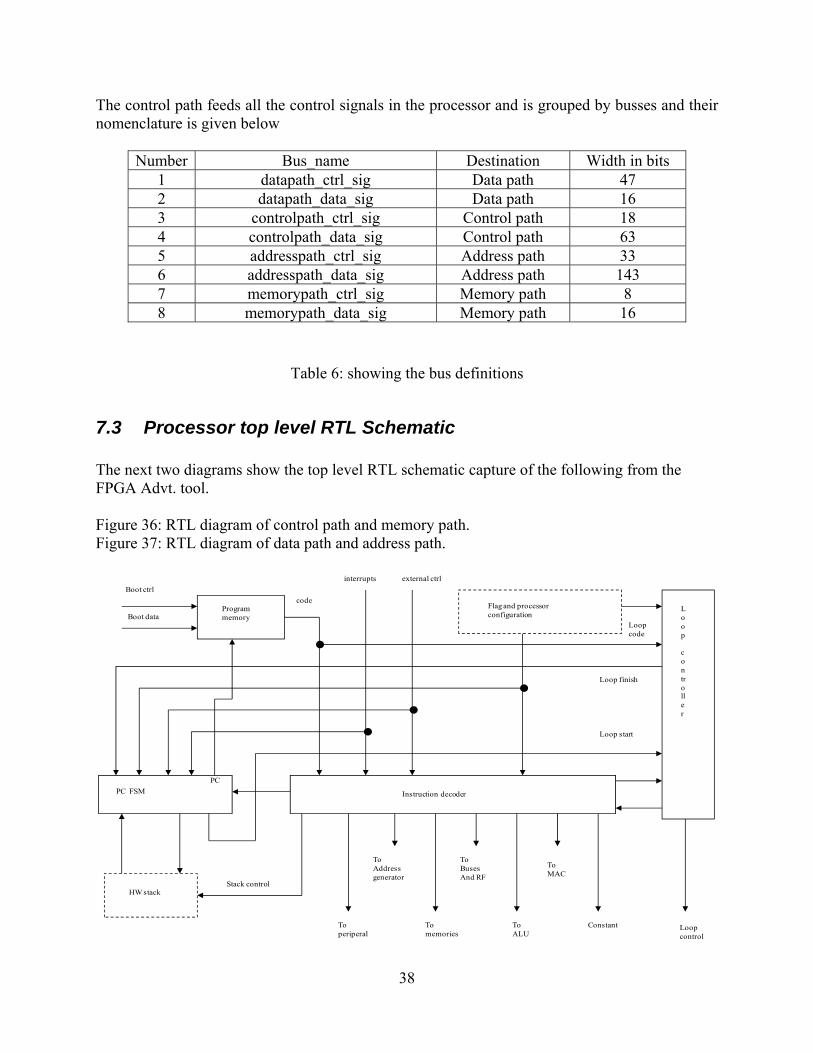
7.3 Processor top level RTL Schematic The next two diagrams show the top level RTL schematic capture of the following from the FPGA Advt. tool. Figure 36: RTL diagram of control path and memory path. Figure 37: RTL diagram of data path and address path.
Boot ctrl
Boot data
code
interrupts external ctrl
Flag and processorconfiguration
Loop
controller
Instruction decoderPC FSM
PC
HW stack
Loopcode
Loop finish
Loop start
Stack control
Programmemory
Toperiperal
ToAddressgenerator
Tomemories
ToBuses And RF
ToALU
ToMAC
Constant Loopcontrol

agu_0_splr_data_o(15:0)
data0_o(15:0)
alu_flag_wr_en
clk
dec_mac_adder_ctrl
dec_mac_integerctrl
dec_mac_sel_1
dec_mac_sel_2
dec_mac_sel_5
dec_mac_sel_6
dec_mac_sel_7
dec_mac_sel_8
dec_mac_sign1
dec_mac_sign2
dec_rf_wren_ctrl
mac_flag_wr_en
rst
carry_o
flags_o
macflag_o
aludata_i(15:0)
dec_alu_mux1_sel(1:0)
dec_mac_sel_10(1:0)
dec_mac_sel_11(1:0)
dec_mac_sel_12(1:0)
dec_mac_sel_13(1:0)
dec_mac_sel_3(1:0)
dec_mac_sel_4(2:0)
dec_mac_sel_9(1:0)
dec_rf_datamux_sel(3:0)
dec_rf_enable_sel(3:0)
dec_rf_opa_sel(3:0)
dec_rf_opb_sel(3:0)
dm0data_i(15:0)
dm1data_i(15:0)
immediatedata_i(15:0)
portidata_i(15:0)
splrdata_i(15:0)
stackdata_i(15:0)
aluout_o(15:0)
opa_clk_o(15:0)
opa_noclk_o(15:0)
opb_clk_o(15:0)
opb_noclk_o(15:0)
register_15_o(15:0)
Data_Path
clk
dec_agu0_adder_ctrl
dec_agu1_adder_ctrl
rst
ag_0_value_i(15:0)
ag_1_value_i(15:0)
bot_0_value_i(15:0)
bot_1_value_i(15:0)
dec_agu0_sel_1(1:0)
dec_agu0_sel_2(1:0)
dec_agu0_sel_3(2:0)
dec_agu0_sel_4(1:0)
dec_agu0_sel_5(1:0)
dec_agu0_sel_6(1:0)
dec_agu0_sel_7(1:0)
dec_agu1_sel_1(1:0)
dec_agu1_sel_2(1:0)
dec_agu1_sel_3(2:0)
dec_agu1_sel_4(1:0)
dec_agu1_sel_5(1:0)
dec_agu1_sel_6(1:0)
dec_agu1_sel_7(1:0)
immediate_data_i(15:0)
opa_i(15:0)
opb_i(15:0)
step_0_value_i(15:0)
step_1_value_i(15:0)
top_0_value_i(15:0)
top_1_value_i(15:0)
agu_0_address_o(15:0)
agu_0_splr_data_o(15:0)
agu_1_address_o(15:0)
agu_1_splr_data_o(15:0)
Address_Path
datapath_ctrl_clk_2_25_0_o(25:0)
agu_1_splr_data_o(15:0)
agu_1_address_o(12:0)
datapath_ctrl_clk_2_28_26_o(2:0)
datapath_data_clk_2_o1(15:0)
agu_0_address_o(12:0)
portidata_i(15:0)
datapath_ctrl_clk_2_37_29_o(8:0)
stack_o(15:0)
data1_o(15:0)
datapath_ctrl_clk_1_o1(7:0)
splr_data_o(15:0)
rst
clk
addresspath_ctrl_clk_1_o(33:0)
opa_clk_o(15:0)
addresspath_data_clk_1_o1(143:0)
carry_o
flags_o
macflag_o
register_15_o(15:0)
rst
opa_clk_o1(15:0)

39
7.4 Precision synthesis The tool used for synthesize is precision synthesize from mentor. Some of the advantages are given below [6]
Improved efficiency through easy and intuitive user interface Excellent language support. The tool also calls the Qartus II software to perform the mapping and assembly steps in
synthesis. Language neutrality supports any combination of VHDL, Verilog, SystemVerilog and
EDIF usage
7.5 Area info for the cyclone II FPGA The whole design is made synthesizable and made to fit in an FPGA, in this case cyclone II. The tool used here is precision synthesis from mentor. The area info for that family is provided below in the table. The timing report and timing violation reports and the .edf file are produced from the precision synthesize tool.
Device Utilization for EP2C35F672C
Resources Used Avail Utilization IO’s 128 475 26.95%
LUT’s 2651 33216 7.98% Register’s 1264 33216 3.81%
Memory bit is 327680 483840 67.72% DSP block 9-bit elem. 2 70 2.86%
Table 7: Area report for cyclone II FPGA

40
Figure 38: showing pie chart for device utilization EP2C35F672C
IO's, 26.95%
LUT's, 7.98%
Register's, 3.81%
Memory Bit's, 67.72%
DSP block 9'bit elements, 2.86%

41
8 Simulations and Verification
8.1 Block level Simulations and Verification In the intellectual property designing process, each block is designed separately and then coded using the HDL language. These blocks must be verified before we integrate the small blocks with one another thus we need to simulate and verify the design. The modelsim simulator tool is used for these purposes. This is a very important aspect in the design which makes it to be error free.
8.2 Functional Verification Does the proposed design do what it is intended to do? [7] This is called as functional verification. It checks that the logic works correctly. This is a bit time consuming and takes more time in the design process. In this design process, each block is designed using HDL and then simulated and tested for various inputs combinations and the expected results are checked. Each unit in the data path, address path memory path and control path is been checked thoroughly.
8.3 Testing The design is tested by various tests like checking with the test bench for each individual module, then individual paths then the whole design. All tests including random tests and corner cases are tested for the design and the activities and changes are noted down carefully for any bugs. If any bugs are found then found bugs are fixed by correcting the RTL. Note that the debugging does not include additional bugs in the design. So after correcting the RTL, the design is simulated again and the results are compared with the last good simulated results. This process is called regression testing.
8.4 Test Bench with application level testing A test bench is a virtual environment used to verify the correctness or soundness of a design or model [8]. The design is finally integrated and tested; it is time for the design to run an application on it. The processor core is tested by testing with a clock generator in a Test bench setup. The clock generator consists of various processes. Clock generator is used to generate a clock for the processor. Reset generator is for generating resets at the initial process. Program memory initializations are where the program memory is loaded with the program. Data memory initializations are where the data memory is loaded with coefficients and data.

42
8.4.1 Top level arrangement
Figure 39: window showing test bench set up with a clock generator
8.4.2 Program The design is tested by a small application program which is given by
Begin NOP; NOP; NOP; SET AG0 "0000000000000000"; SET AG1 "0000000000000000"; SET STEP0 "0000000000000001; SET STEP1 "0000000000000001; NOP; NOP; NOP; REPEAT 3, 4; CONV SS F u1 u2 Z ACRd, DM0 (AM) DM1 (AM); NOP; NOP; NOP; NOP; MOVE SSrs Rd, ACRa; -- rounded and scaled by 2 End;
The above program is given in binary and stored in the program memory and then executed. First the special registers are set and the CISC CONV instruction is tested Because of the repeat 3, 4, the next three instructions are repeated four times and the resulted is rounded and scaled by 2 and moved to the general register15. The results are shown in the simulations windows below.

43
8.4.3 Simulation results
Figure 40: window showing the simulations start window where the yellow marker shows the program counter starts i.e. from the first instruction.
Figure 41: window showing the simulations where the yellow marker at 13190 ns shows the start
of the repeat instruction followed by CONV.

44
Figure 42: window showing the simulations start window where the yellow marker at 15201 ns
shows the third and fourth dm 0 and dm 1 read for convolution.
Figure 43: window showing the simulations start window where the yellow marker at 17002 ns
shows the output from the accumulator is scaled by 2 and moved to the general register15.

45
9 Power simulations
9.1 Power Simulation Power consumption is an important feature to be considered in system implementations. This work presents a methodology for power consumption estimation using Quartus® II software. The power estimation provides an accurate way to estimate the power consumed by your design because it is based on the simulation stimuli that reflects the actual design behavior. It is important to remember that these results should only be used as an estimation of power, not as a specification. The total device current should be verified during device operation as this measurement is sensitive to the actual implementation in the device and to the environmental operating conditions [9].
9.2 Quartus II - Power Play Power Analyzer The Quartus® II software has a inbuilt power tool called power play power analyzer which has a power estimation feature that uses our design simulation vector files to estimate the power consumption of the device based on typical device operating condition. It represents the more accurate toggle rate of the design since it calculates this from the simulation output from the design, such as a value change dump (VCD) file.
Figure 44: flow diagram for power analysis
Modelsim
Test Bench Design Net List
VCD file
Quartus II
Power analysis results

46
First the complete design net list is simulated in the modelsim software using a test bench program. Create a VCD file before the simulation is started and add all the signals to the region so that all stimuli changes are traced. The following commands are used for the purposes.
Vcd file my_design.vcd - Creates a .VCD file. Vcd add -file.my_design.vcd -r/top_level_entity/* - adds the entire signal in that region. Vcd dumpports –file my_design.vcd/ top_level_entity/* - for extended vcd file format.
Once the vcd file is created, run the simulation and the file size keeps on increasing when tracing all the toggles. Open the Quartus® II software, import the design, compile and analyze it, then open the power play power analyzer tool, select the top level entity of the design, add the vcd file and run it. The results are shown below.
9.3 Results
Power consumption in any digital CMOS circuits is given by P = Pstatic +Pdynamic. [10, 11].The power simulation results are shown below for Altera, cyclone II family. The corresponding thermal dissipation, core dynamic, core static and I/O power dissipation are given below in the graph for the core designed.
Figure 45: graph showing power comparison between two devices for the core
128.07
214.1
5.95 8.43
79.98
155.16
42.14 50.15
EP2C35F672C6 EP2C70F672C7
Power dissipation of the core in mW
Total Thermal power dissipation Core dynamic thermal power dissipation
Core static thermal power dissipation2 I/O thermal power dissipation

47
Figure 46: graph showing block level power dissipation for EP2C35F672C6 The power simulation results shown in the graph shows the highest power consuming device is the Id + pipelining logic due to the large number of registers in the pipeline logic. Next comes the memories. The simulation-based power estimation feature in the Quartus II software is an easy and useful tool to estimate the power consumption for simple designs, based on typical conditions. [9]
0 1 2 3 4 5 6
EP2C35F672C6
Total thermal dissipation by hierarchy in mW
mac
rf
alu
pm
dm1
dm0
addr_data_sel_dm1
addr_data_sel_dm0
agu_1
agu_0
pc
stack
lc
id+pipeline logic
fsm
data_path
memory_path
address_path

48
Figure 47: graph showing block level power dissipation for EP2C70F672C7
0 1 2 3 4 5 6
EP2C70F672C7
Total thermal dissipation by hierarchy in mW
mac
rf
alu
pm
dm1
dm0
addr_data_sel_dm1
addr_data_sel_dm0
agu_1
agu_0
pc
stack
lc
id+pipeline logic
fsm
data_path
memory_path

49
10 Conclusions
10.1 Results and Future works Started from the literature review and algorithm, finally the processor is designed in VHDL language and made synthesizable and targeted for an FPGA. Simulation based power simulations are also run for the design and the results are tabulated. There are a lot of DSP algorithm and different architectures available, we cannot say that which is good or bad overall but we can say which would be suitable for a particular DSP application. Future works would be to make the design still flexible so that we can add a DMA controller, more I/O interfaces and sleep mode.

50

51
11 Acronyms and Abbreviations DSP Digital Signal Processing FIR Finite Impulse Response IIR Infinite Impulse Response FFT Fast Fourier Transform AIS Assembly Instruction Set ACR Accumulator Registers DP Data Path CP Control Path ALU Arithmetic and Logic Unit MAC Multiplication and Accumulation LC Loop Counter PC Program Counter FSM Finite State Machine HW Hard Ware SW Soft Ware ID Instruction Decoder RF Register File AGU Address Generation Unit PM Program Memory DM Data Memory FF Flip Flop KB Kilo Bytes MMC Machine to Man Communication MSB Most Significant Bit LSB Least Significant Bit LIFO Last In First Out FIFO First In First Out ROM Read Only Memory RAM Random Access Memory TTM Time to Market WCET Worst Case Execution Time ASIC Application Specific Integrated Circuit ADC Analog to Digital Converter DAC Digital to Analog Converter DMA Direct Memory Access RTL Register Transfer Level RISC Reduced Instruction Set Computer CISC Complex Instruction Set Computer ISA Instruction Set Architecture ASIP Application Specific Integrated Processor HDL Hardware Description Language IF Instruction Fetch

52
AG Address Generation EX Execute RD Read OP Operand Fetch ST Store WR Write EN Enable WB Write Back MEM Memory MUL Multiplication

53
12 Appendix I
11.1 Assembly Instruction Set Manual
1. Pipelined architecture: Generally DSP processors are not RISC or CISC, but it is a RISC with CISC enhancements. The instructions are divided into four pipeline groups as mentioned below:
Group Sub-division Stage 1 Stage 2 Stage 3 Stage 4 Stage 5
RISC
others IF ID OF EX
memory-Store IF ID AG/OF Store EX
CISC
memory-Load IF ID AG/OF Load EX
Conv IF ID AG OF EX
Table 8: showing pipeline groups and stages
In this core we have generally RISC instructions but two CISC instruction which is “CONV” and memory load. Typical pipeline of a RISC instruction is different from a CISC instruction. The below table shows all the instructions available which can be used in the processor to program it and their identity as CISC or RISC.
S.No Instructions RISC/CISC Stages in Pipeline
1 LOAD Rd, DMy (AM)
CISC 5
2 LOAD Rd, #IMM RISC 4 3 STORE DMy(AM), Ra RISC 4 4 STORE DMy(AM), #IMM RISC 4 5 SET SPLRD, #IMM RISC 4 6 INP Rd, PortI RISC 4 7 OUTP PortO, Ra RISC 4 8 MOVE Rd, ACRaH/L RISC 4 9 MOVE Rd, ACRa RISC 4 10 MOVE ACRdH/L, Ra RISC 4 11 MOVE Rd, SPLRa RISC 4

54
12 MOVE SPLRd, Ra RISC 4 13 Push Ra RISC 4 14 Pop Rd RISC 4 15 MAC U1 U2 I/F ACRd, Ra Rb RISC 4 16 ADD ACRd, ACRa ACRb RISC 4 17 ADD Rd, Ra Rb RISC 4 18 DEC Rd RISC 4 19 CLR ACR RISC 4 20 CMP Rd, #IMM RISC 4 21 CONV Z U1 U2 I/F ACRd, DM0(AM)
DM1(AM) CISC 5
22 POSTOP RND SAT ACRa RISC 4 23 JUMP K RISC 4 24 JUMP NE K RISC 4 25 CALL K RISC 4 26 NOP RISC 4 27 REPEAT P N RISC 4 28 RETURN RISC 4
Table 9: showing all instructions supported by the core
2. Register Specification: There are 16 General purpose registers (GPR) 16 bits each GR0 to GR15 used for computing buffers, 16 special purpose registers (SPLR) 16 bits each SPLR0 to SPLR15 as specified in the Table 1. Both the GPR and SPR are addressed by 4-bits binary code. The special registers are only accessed by SET and MOVE instructions.
Name
Location Address code Specification
AG0 AGU 0000 Address register 0 AG1 AGU 0001 Address register 1
BOT0 AGU 0010 Bottom for AG0 TOP0 AGU 0011 Top for AG0 STEP0 AGU 0100 Step size for AG0 BOT1 AGU 0101 Bottom for AG1 TOP1 AGU 0110 Top for AG1 STEP1 AGU 0111 Step size for AG1 LOOPS CP 1000 Loop start address LOOPE CP 1001 Loop end address LOOPN CP 1010 Number of iterations in loop reserved -- 1011 --

55
reserved -- 1100 -- reserved -- 1101 -- reserved -- 1110 -- reserved -- 1111 --
Table 10: definitions of special registers
3. Coding Convention: The instructions are classified in to four groups. Please refer to the below table. The (31 down to 30) bits decides the group, subdivided into Load-Store, Move, Arithmetic and Program flow Instructions.
Group code Instruction_i [31:30] Specification
00 Load-Store Instructions
All STORE, LOAD, SET, OUTP, INP.
01 Move Instructions
All Move instructions including PUSH, POP.
10 Arithmetic Instructions
All arithmetic including MAC,CLR,CMP,CONV and POSTOP
11 Program flow control Instructions
Including all jumps, calls, REPEAT, NOP.
Table 11: Instruction Groups
4. Addressing Modes: There are totally 7 addressing modes supported by both the address generation units AGU-0 and AGU-1. Their respective op-codes are given below for the user reference.
AM Code Addressing mode
Coding Algorithm Specification
DIR 000 Direct Immediate 16’b A <= DIR (# imm) INX 001 Indexed Any AG or GR A <= AGn + Ra RID 010 Register-indirect Any GR A <= Ra
MOD
011
Modulo
Any AG
A <= AGn; AGn = AGn+STEPn
PAD
100
Post-add
Any AG
A <= AGn; AGn = AGn+STEPn

56
PSB
101
Pre-subtract
Any AG
AGn = Agn - STEPn;
A <=Agn;
BRV
110
Bit-reversed
Any AG A <= Bit Reversed
(AGn);
Table 12: Definitions for various addressing modes Comments:
A - Address AGn - Address register AG0/1 Ra - General register GR0 to GR15 as source register STEPn - Step registers (either STEP0 or STEP1) MOD - Need to set the TOPn and BOTn register PAD - Don’t need to set the TOPn and BOTn registers
5. Coding for ACR addressing:
ACR code (A,D) ACR 0 ACR0 1 ACR1
Table 13: Showing (ACR0 or ACR1)
Table 14: Showing ACR (ACRH or ACRL)
Comments:
A - ACR 0 or ACR1 for accumulator register as a source register ACRa D - ACR 0 or ACR1 for accumulator register as a destination register ACRd
6. Coding for data memory:
DM code (y) Description 0 DM-0 1 DM-1
ACRH/L code (h) ACRH or ACRL 0 Lower Part 1 Higher part

57
Table 15: Showing DM (DM0 or DM1)
7. Flags:
S.No
Flag Name Description
1 ALZ Zero flag of the ALU 2 ALS Saturation flag of the ALU 3 MACS Saturation flag of the
MAC
Table 16: Definitions for various flags
8. Saturation, round and scaling: Since the processor architecture is fixed length i.e., 16 bits, it is better to implement a saturation arithmetic where the value is between a maximum and minimum value. The core also has a rounding and scaling function options where are depicted in the table below.
Scaling factor [SS] Description 00 1 01 2 10 0.5 11 0.25
Table 17: scaling
Comments: SS -Used in the MAC unit, see the instruction set encoding for more details
Round [r] Description 0 Round off 1 Round on
Table 18: rounding

58
Comments: r - Rounded to 16 bits.
Saturation factor[s] Description 0 Saturation off 1 Saturation on
Table 19: saturation
9. Jump Conditions: Jumps are divided into conditional jump and unconditional jump. In conditional jump the condition check for the ALU flag for a zero and if satisfies the condition logic sets the output to the FSM where the unconditional jumps simply jumps to the given 16’b address. The below table shows the bit C for conditional and unconditional jump.
Bit [C] Condition 0 Unconditional Jump 1 Conditional Jump
Table 20: jump conditions
10. Load and Store Instructions: No Mnemonics OP code Description Operations
1 LOAD
000 Loads the content of the specified memory location to the destination
Register
Rd ← DMy (AM)
2 001 Loads the Immediate value to destination register
Rd ← Immediate 16’b
3 STORE
010 Stores the register value to the specified memory location
DMy (AM) ← Ra
4 011 Stores the Immediate value to the specified memory location
DMy(AM) ← Immediate 16’b

59
5 SET 100 Set the special register SRd to immediate 16'b value.
SPRd ← 16’b immediate
6 INP 101 Port read Rd ← INP
7 OUTP 110 Port write OUTP ← Ra
8 SETG 111 Set the general register, any 15 registers to immediate 16'b value.
Rd ← Immediate 16’b (Not added, if needed can
be added)
Table 21: Showing load, store instructions LOAD: Instruction: LOAD Rd DMy (AM) : Load data from DM0/1 to a general register.
LOAD Rd #IMM : Load the immediate value to a general register.
Operation:
LOAD - Rd ← DM 0/1(AM) LOAD - Rd ← #IMM
Coding: DMy - Select DM0 or DM1
Rd - General registers GR0 to GR15 as a destination register AM - Addressing mode # IMM: 16’b value
STORE: Instruction: STORE DMy AM # IMM - Store the 16’b immediate value to memory DM0/1
STORE DMy AM Ra - Store the register value to the data memory DM0/1 Operation:
STORE: DM0/1(AM) ← 16´b value STORE: DM0/1(AM) ← Ra
Coding:

60
DMy: Select DM0 or DM1 Ra: general registers GR0 to GR15 as a source register AM: Addressing mode # IMM: 16´b value
SET: Instruction:
SET SPLRd #IMM - Load a 16’b immediate data to a special register Operation: SPLRd ← 16´b value Coding:
SPLRd: Special register SR0 to SR15 as destination register INP: Instruction: INP Rd PortI Operation: Rd ← value of PortI (read value from PortI to Rd) Coding: Rd: general registers GR0 to GR15 used as a destination register OUTP: Instruction: OUTP Porto Ra Operation: Porto ← Ra (write value of Ra to PortO) Coding:

61
Ra: general registers GR0 to GR15 used as a source register.
11. Move Instructions: No Mnemonics OP code Description Operations
1
MOVE
000 Move accumulator (Higher/Lower part) to general
Rd ← ACRaH/L
2 001 Move accumulator to general Rd ← sat(rnd(scaling(ACRa)))
3 010 Move general to accumulator ACRdH/L ← Ra
4 011 Move Special register to general
Rd ← SPLRa
5 100 Move general to Special register
SPLRd ← Ra
6 PUSH 101 Hardware stack push Stack ← Ra
7 POP 110 Hardware stack pop Rd ← Stack
Table 22: Showing move instructions
MOVE: Instruction:
MOVE Rd, ACRaH/L - Move data from accumulator (higher or lower part) to general register Rd.
MOVE SSrs Rd, ACRa - Move data from accumulator to general register Rd. MOVE ACRdH/L, Ra - Move content of general register to the accumulator. MOVE Rd, SPLRa - Move content of special register to the general register. MOVE SPLRd, Ra - Move content of general register to the special register. Operation:
Rd ← ACRaH/L Rd ← sat (rnd (scaling (ACRa))) ACRdH/L ← Ra Rd ← SPLRa SPLRd ← Ra

62
Coding: ACRaH: Higher part of the accumulator registers ACR as source register. Rd: general register GR0 to GR15 as destination register. ACRaL: Lower part of the accumulator register nACR as source register. Ra: General registers GR0 to GR15 as source register. SPLRs: Special register SPLR0 to SPLR15 as source register. SPLRd: Special register SPLR0 to SPLR15 as destination register. ACRa: Accumulator 0 or accumulator 1as source. SS: Scaling (it is a factor of 2) S: Saturation. r: Rounding. PUSH: Instruction:
Push Ra - Move data from reg to stack Operation:
Stack ← Ra Coding:
Ra: General registers GR0 to GR15 as source register.
POP: Instruction:
Pop Rd - Move data from stack to reg. Operation:
Rd ← Stack Coding: Rd: General registers GR0 to GR15 as destination register.

63
12. Arithmetic Instructions: No Mnemonics OP code Description Operations
1 MAC 000 Multiply and accumulate ACRd ← (scaling(ACRa+ (Ra* Rb)))
2 ADD 001 Addition wACRd ← sat (ACRa + ACRb)
3 ADD 010 Addition Rd ← Ra + Rb
4 CLR 011 Clear the accumulator value to zero
wACR ← 0
5 CMP 100 Compare Compare (Ra, #IMM)
6 CONV 101 Convolution
wACR ← scaling(wACR +/- (DM0(AM) *
DM1(AM))) 7 POSTOP 110 Perform post operation on
ACR wACR ←
sat(rnd(scaling(wACRa)))
8 DEC 111 Decrement the destination register by 1
Rd← Rs – 1
Table 23: Showing arithmetic instructions
MAC: Instruction:
MAC SS F u1 u2 wACR, Ra Rb;
Operation:
wACR ← (scaling (ACR + {Ra * Rb})) Coding:
Ra: General registers (AG0 to 15) as source register.
Rb: General registers (AG0 to 15) as source register. ACRa: Accumulator registers 0/1 as source register. ACRd: Accumulator registers 0/1 as destination register. SS: Scaling (it is a factor of 2) S: Saturation.

64
r: Rounding. u1: Signed / unsigned for operand A type. u2: Signed / unsigned for operand B type. SS: Scaling factor 0.5 for fractional multiplication. F: fractional / Integer.
ADD: Instruction:
ADD ACRd, ACRa ACRb Operation:
wACRd ← sat ((wACRa + wAcRb)) Coding: ACRd: Accumulator registers 0/1 as destination register ACRa: Accumulator registers 0/1 as source register ACRb: Accumulator registers 0/1 as source register SS: Scaling (it is a factor of 2) S: Saturation r: Rounding ADD: Instruction:
ADD Rd, Ra Rb Operation:
Rd ← Ra + Rb Coding: Rd: General registers Gr0 to Gr15 as a destination register. Ra: General registers Gr0 to Gr15 as a source register. Rb: General registers Gr0 to Gr15 as a source register.
CLR: Instruction:
CLR ACRa, 0

65
Operation:
ACR ← 0 Coding: ACRa: Accumulator registers 0/1 0: Value zero CMP: Instruction:
CMP Rd, #IMM Operation:
FLAG ← #IMM – Rd Coding: Rd : General registers Gr0 to Gr15 as a destination register # IMM: A 16’b binary value
CONVOLUTION: Instruction:
CONV SS F u1 u2 Z ACRd, DM0 (AM) DM1 (AM); Operation:
For I = 1 to N ++ {
OPA DM0(AM); OPB DM1(AM); MUL OPA * OPB; ACRd wACRd +/- (guard MUL));
} Coding:
AM: Addressing mode

66
Z: Plus or minus (+ or -) DMx: Data memory 0 / Data memory 1 ACRd: Accumulator registers 0/1 as destination register SS: Scaling (it is a factor of 2) u1: Signed / unsigned for operand A type
u2: Signed / unsigned for operand B type F: fractional / Integer
POSTOP: Instruction:
POSTOP ACRa
Operation:
ACRd ← sat (round (scaling (ACRa))) Coding: ACRa: Accumulator registers 0/1 as source register. ACRd: Accumulator registers 0/1 as destination register. SS: Scaling (it is a factor of 2). S: Saturation. r: Rounding. DEC: Instruction:
DEC Rd Operation:
Rd ← Rs – ‘1’ Coding: Ra: General register or special register as source register. Rd: General register or special register as destination register.
13. Program Flow Control Instructions:

67
No Mnemonics OP code Description Operations
1 JUMP K
000
C = ’0’,Jump to target address
PC ← 16’b value
JUMP NE K C = ‘1’,Jump to value k if previous instructions flag is
not equal to “0”
If true PC ← K If false PC ← PC + 1
2 CALL 001 Call subroutine PC ← #IMM 16’b value
3 NOP 010 No operation This instruction is used for time skimming
4 REPEAT 011 Repeat M instruction N times
M instruction repeated N times
5 RETURN 100 Return to main program PC ← stack
Table 24: Showing program flow instructions
JUMP: Instruction:
JUMP K JUMP NE K
Operation:
PC ← K If true PC ← K If false PC ← PC + 1
Coding: K: 16’b constant (address). PC: Program counter. NE: not equal to “0”. CALL: Instruction:
CALL K Operation:

68
PC ← K; Call a subroutine, push PC to stack and get a target address.
Coding: K: 16’b constant (address). PC: Program counter.
NOP: Instruction:
NOP Operation:
PC ← PC+1; Just increases the program counter by one without doing anything Coding: PC: Program counter. NOP: No Operation (Do nothing). REPEAT: Instruction:
REPEAT P N Operation:
RPEAT P N; Repeat following P instructions N times. For I = 1 to N ++ {
Instruction 1 Instruction 2 Instruction 3 Instruction 4 Instruction 5 . . . Instruction P
} Coding:

69
P: P instructions following REPEAT- 7’bits (upto128). N: Running REPEAT for ‘N’ times - 8’bits (upto 256 iterations).
N cannot be ‘0’ or ‘1’.
RETURN: Instruction:
RETURN Operation:
PC ← stack Coding: PC: Program counter
14. Instruction set encoding: This session shows how the above instructions are represented in binary. There are different instructions which have different operands and will need different representations, for example
1. Register format which require two source registers.
2. Immediate format which require one source register and one constant operand.
3. Jump and branch format require one source register and one constant address. Irrespective of their formats, it is always best to make their binary representation as similar as possible. This will definitely make the control unit simpler in hardware. In this case all the instructions are 32’b long.
14.1. Load-store instructions

70
33222222222211111111110000000000 10987654321098765432109876543210 00000ddddy...mmmiiiiiiiiiiiiiiii LOAD Rd, DMy (AM);
i<= direct addressing ddddy...000iiiiiiiiiiiiiiii y<= DM (0 or 1) ddddy...001ssss............ s<= for index register ddddy...010ssss............ ddddy...011................ ddddy...100................ ddddy...101................ ddddy...110................ Bit reversed addressing 00001dddd.......iiiiiiiiiiiiiiii LOAD Rd, #IMM 00010.mmmyaaaa..iiiiiiiiiiiiiiii STORE DMy (AM), Ra ; .000yaaaa..iiiiiiiiiiiiiiii .001yaaaa..ssss............ s<= For index register .010yaaaa..ssss............ .011yaaaa.................. .100yaaaa.................. .101yaaaa.................. .110yaaaa.................. bit reversed addressing 00011ssssy...mmmiiiiiiiiiiiiiiii STORE DMy (AM), #IMM –
addressing mode is register indirect (mmm = 010)
00100dddd.......iiiiiiiiiiiiiiii SET SPLRD, #IMM 00101dddd.......pppppppppppppppp INP Rd, PortI in DM0 00110.....aaaa..pppppppppppppppp OUTP PortO, Ra in DM0 (pp...p) is the memory address _ _
14.2. Move instructions: 33222222222211111111110000000000 10987654321098765432109876543210 01000dddd.....hA................ MOVE Rd, ACRaH/L; A<= ACR (0 or 1) h<= ACR (H or L) 01001dddd......A............SSrs MOVE Rd, ACRa;
SS<= scaling R<= rounding s<= saturation
01010.....aaaah.D............... MOVE ACRdH/L, Ra; D<= ACR (0 or 1) 01011dddd.aaaa.................. MOVE Rd, SPLRa; 01100dddd.aaaa.................. MOVE SPLRd, Ra; 01101.....aaaa.................. Push Ra; 01110dddd....................... Pop Rd;

71
_ _
14.3. Arithmetic instructions: 33222222222211111111110000000000 10987654321098765432109876543210 10000SS...aaaa..D....fuu....bbbb MAC U1 U2 I/F ACRd, Ra, Rb; u (9) = U1, u (8) = U2 10001...........D..............s ADD ACRd, ACRa ACRb; 10010dddd.aaaa..............bbbb ADD Rd, Ra Rb; 10011...........D............... CLR ACR; 10100dddd.......iiiiiiiiiiiiiiii CMP Rd, #IMM; 10101SS....mmm..D....fuu....Zmmm CONV Z U1 U2 I/F ACRd, DM0 (AM) DM1 (AM); Z<= (+ 0r -) mmm = only modulo, post-increment,
pre.dec. and bit reversed. 20-18 = for dm0 2-0 = for dm1 10110...........D...........SSrs POSTOP RND SAT ACRa; 10111dddd.aaaa.................. DEC Rd by 1 aaaa and bbbb are same registers _ _
14.4. Program flow instructions: 33222222222211111111110000000000 10987654321098765432109876543210 11000..........Ciiiiiiiiiiiiiiii JUMP K and JUMP NE K; C <= one bit which defines condition jump or unconditional jump 11001...........iiiiiiiiiiiiiiii CALL K; 11010........................... NOP; 11011....ppppppp........nnnnnnnn REPEAT P N; N= no. of times 11100........................... RETURN;

72

73
13 Appendix II
12.1 Coding Conventions
1. Coding convention for ASIP DSP core “HDL coding should start with a top-down design approach. Use a top-level block diagram to communicate to designers the naming required for signals and hierarchical levels. Signal naming is especially important during the debug stage. Consistent naming of signals, from top to bottom, will ensure that project manager A can easily recognize the signals written by designer B” [12]
2. Language The language used is VHDL VHDL – VHSIC Hardware Description Language VHSIC – Very High Speed Integrated Circuit Why VHDL: Even though it is a very strong typed language it is very robust and powerful for users with good knowledge. It is not the only one but there are many ways to model the same circuit with large hierarchical structures. Secondly, there are more constructs and features for high level modeling in VHDL than in Verilog. For large designs VHDL is best since it supports statements line configuration, generic, generate and packages and VHDL is very good for reusability. I.e. Procedures and functions may be placed in a package so that we can use them for any design unit. Finally VHDL is components can be verified functionally in a simulator and its been standardized, which makes us move the code between different development systems.
3. Indentations Indentations are for easy readability and reuse. Many text editors are vhdl aware, text editors like Emacs and Code Wright automatically indents blocks of code. Indentations should be 4 spaces.

74
4. Clock Scheme: “In a synchronous design, only one clock and one edge of the clock should be used” …. Xilinx [13], so everything must be synchronous to one and only one clock.
5. Reset The reset used is a Synchronous reset. If, Then, Else or Case statements: According to Xilinx the synthesis tool handles these statements very well to create a parallel logic rather than creating a encoded logic.
6. Sensitivity List
6.1. For Combinational process:
o All signal that are read (which can change) must be in the sensitivity list o This also includes any signals which are compared in If- Then, Else or case statements. o This also includes any signal on the right hand side of the assignment operator. o No need for constants in sensitivity list because it cannot change.
6.2. For Clocked process: o Only the asynchronous set or reset or clock should be in the sensitivity list. o Even the simulation would be correct if others are added in the list but the simulation will
be slower because we know that the processes will have to evaluate or simulate whenever a signal in the sensitivity list changes.
6.3. Assignments:
In a combinatorial process blocking assignments have been used. In a sequential process, non blocking assignments have been used.

75
7. Naming Conventions Naming conventions are used for to understand other code very easily. The general naming guidelines as per Xilinx are
o addr for address. o rst for reset. o Inputs to all modules should end in _i. o Outputs to all modules should end in _o. o Bidirectional ports to all modules should end with _io. o for all signals, should end with _sig. o Constants should be used in upper case; everything else should be used in lower case.
8. General syntax (Origin module)_ (destination module) _ (corresponds to which signal) _ (sel/i/o/sig)
8.1. Examples:
Case 1: dec_rf_opb_sel: dec signal is from the decoder module rf means that the signal is going to the register file module opb corresponds to operad b in the register file sel it is a select signal of the multiplexer used to select op b
Case 2: opb_sel_i opb corresponds to operad b in the register file sel it is a select signal of the multiplexer used to select op b _i it is an input signal Case 3: rf_opb_sel_o
The above signal is the output of the decoder. rf_opb_sel_o Signal should go into the register file

76
9. Suffix Summary _reg flip flop
_sig signal _i module input _o module output _sel MUX select signal
10. Note
o The decoder module is very special and signals from the decoder module almost go to every other module. That is why it is necessary to prefix signal with the destination module.
o For registers and flip flops, _reg has been used as a suffix to distinguish them from combinatorial signals. The combitorial signals have been added with a suffix _sig.

77
13 Reference [1] Wikipedia.org dated December 01, 2008. http://en.wikipedia.org/wiki/Application-specific_instruction-set_processor
[2] A Low-cost and Application driven digital signal processor for speech and audio
processing by Jen-Feng Chung and Chin-Teng Lin, The 2004 IEEE Asia-Pacific Conference. http://ieeexplore.ieee.org/iel5/9700/30610/01412773.pdf
[3] Digital filter equation from Bores, dated October 20th, 2008. http://www.bores.com/courses/intro/iir/5_eq.htm [4] Chapter 2, Numerical representation and finite length DSP from Design of Embedded
DSP Processors, Text book (compendium) by Dake Liu, 2007. [5] Chapter 7, Assembly instruction set design, 90%-10% code locality rule from Design of
Embedded DSP Processors, Text book (compendium) by Dake Liu, 2007. [6] Mentor, dated October 22, 2008. http://www.mentor.com/products/fpga_pld/synthesis/precision_rtl/ [7] Functional verification from Wiki.org, dated October 22, 2008. http://en.wikipedia.org/wiki/Functional_verification [8] Test Bench from Wiki.org, dated October 22, 2008. http://en.wikipedia.org/wiki/Test_bench [9] Power calculator user guide, version 2.0, Altera for Power estimation in Stratix, Stratix
GX, and Cyclone Devices. http://www.altera.com/literature/ug/ug_PC.pdf
[10] James Ross Goodman, "Energy Scalable Reconfigurable Cryptographic Hardware for
Portable Applications", Ph.D thesis, Massachusetts Institute of Technology, August 2000. [11] Thomas David Burd, "Energy− Efficient Processor System Design", Ph.D thesis,
University of California,Berkeley, Spring 2001. [12] Document for “Coding style guidelines” for fast reliable and reusable HDL code. Reference link on web: http://www.ece.northwestern.edu/~seda/coding_guidelines_013003.pdf [13] Xilinx.com, code writing guidelines dated October 22, 2008. [14] The Application of programmable DSP’s in mobile communications, published online on
18th April, 2002 by Alan Gatherer and Edgar Auslander.

78
På svenska Detta dokument hålls tillgängligt på Internet – eller dess framtida ersättare – under en längre tid från publiceringsdatum under förutsättning att inga extra-ordinära omständigheter uppstår. Tillgång till dokumentet innebär tillstånd för var och en att läsa, ladda ner, skriva ut enstaka kopior för enskilt bruk och att använda det oförändrat för ickekommersiell forskning och för undervisning. Överföring av upphovsrätten vid en senare tidpunkt kan inte upphäva detta tillstånd. All annan användning av dokumentet kräver upphovsmannens medgivande. För att garantera äktheten, säkerheten och tillgängligheten finns det lösningar av teknisk och administrativ art. Upphovsmannens ideella rätt innefattar rätt att bli nämnd som upphovsman i den omfattning som god sed kräver vid användning av dokumentet på ovan beskrivna sätt samt skydd mot att dokumentet ändras eller presenteras i sådan form eller i sådant sammanhang som är kränkande för upphovsmannens litterära eller konstnärliga anseende eller egenart. För ytterligare information om Linköping University Electronic Press se förlagets hemsida http://www.ep.liu.se/ In English The publishers will keep this document online on the Internet - or its possible replacement - for a considerable time from the date of publication barring exceptional circumstances. The online availability of the document implies a permanent permission for anyone to read, to download, to print out single copies for your own use and to use it unchanged for any noncommercial research and educational purpose. Subsequent transfers of copyright cannot revoke this permission. All other uses of the document are conditional on the consent of the copyright owner. The publisher has taken technical and administrative measures to assure authenticity, security and accessibility. According to intellectual property law the author has the right to be mentioned when his/her work is accessed as described above and to be protected against infringement. For additional information about the Linköping University Electronic Press and its procedures for publication and for assurance of document integrity, please refer to its WWW home page: http://www.ep.liu.se/ © Vivek Packiaraj