Studio Air Final Journal Ray Zhang
51
RAY ZHANG 699062 SEM 1, 2016 FINNIAN WARNOCK STUDIO AIR JOURNAL
description
Â
Transcript of Studio Air Final Journal Ray Zhang

RAY ZHANG699062
SEM 1, 2016FINNIAN WARNOCK
STUDIO AIRJOURNAL

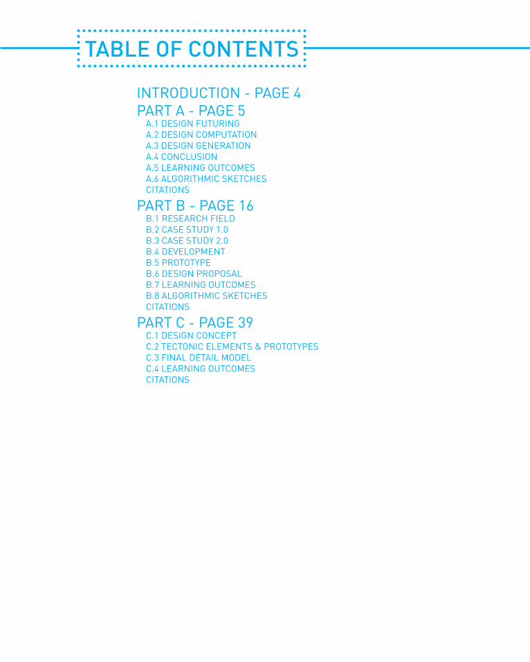
TABLE OF CONTENTS
INTRODUCTION - PAGE 4PART A - PAGE 5 A.1 DESIGN FUTURING A.2 DESIGN COMPUTATION A.3 DESIGN GENERATION A.4 CONCLUSION A.5 LEARNING OUTCOMES A.6 ALGORITHMIC SKETCHES CITATIONS
PART B - PAGE 16 B.1 RESEARCH FIELD B.2 CASE STUDY 1.0 B.3 CASE STUDY 2.0 B.4 DEVELOPMENT B.5 PROTOTYPE B.6 DESIGN PROPOSAL B.7 LEARNING OUTCOMES B.8 ALGORITHMIC SKETCHES CITATIONS
PART C - PAGE 39 C.1 DESIGN CONCEPT C.2 TECTONIC ELEMENTS & PROTOTYPES C.3 FINAL DETAIL MODEL C.4 LEARNING OUTCOMES CITATIONS

PAGE 4
RAY ZHANGAUSTRALIA
University of Melbourne, Bachelor of Environments [2014-present]
I’m a twenty year old born and raised in Melbourne who is currently studying a Bachelor of Environments at The University of Melbourne with a major in Architecture.
From an early age I always had a sort of creative side and an interest in houses. Around my first year of primary school I had a hobby of browsing through real estate magazines because I really liked looking at the prices of houses (for some odd reason) but also the different types of houses and what sort of cool designs they had. I also liked LEGO a lot as a kid, crafting anything from buildings to vehicles. As I sort of grew up I did always have a creative side, enjoying photo editing, writing, game-programming. Basically anything that kind of let your imagination run free.
When it came to picking a university course architecture felt like a good fit to me. It tied into my younger days of loving houses and LEGO and was something that would allow me to design and use my imagination.
As for what sort of designer I am, personally I thinkI’m someone who thinks a lot of the context, especially historical and social context. I would like to think my designs would be very “functional” and represent something to the people who use/see it.
Software wise, I am very comfortable with AutoCAD, Sketch-Up and Adobe Photoshop and after this subject I’m hoping my proficiency with Rhino, Grasshopper and Illustrator is at a intemediate level.
INTRODUCTION

PAGE 5
PART A - CONCEPTUALIZATION

PAGE 6
This is Fallingwater, a house designed by Frank Lloyd Wright in 1935 in southwestern Pennsylvania. The building is especially special because it was built over a 30’ waterfall, almost like it was floating. It was most definitely one of the first buildings of it’s time that so expertly blended the manmade with the natural environment. The building itself also really showed off Wright’s organic philosophy. Some examples are the fireplace hearth which uses boulders from the surrounding areas.
Fallingwater had a profound influence on architects around the world, arguably being Frank Lloyd Wright’s finest work to date. Because of how it integrated stone walls with bedrock and modern concrete it can seen as both a building that both defies the modern movement of architecture while at the same time advancing it. To this day it is seen as one of the first acceptances of modern architecture.
The use of natural materials is a throwback to our past with nature but the way the building is setout was at the time a new way to show people space and habitation. Even to this day the design is still appreciated with buildings such as the Sunshine Coast Bush Treehouse basing part of it’s design (roof overhang) heavily on Fallingwater. The design has also inspired numerous fictional buildings in movies such as 1959’s North by Northwest.
FALLINGWATER
A1 - DESIGN FUTURING
In some ways you could argue the building activates the site, the natural looking of the building blends into almost too well with the envionment. This in mainly due to it’s use of two colours of light ochre and Cherokee red and the materials chosen. The site acted as a weekend retreat for the Kaufmann family where they could do outdoor activites and nowadays serves as a tourist attraction that attracts thousands of visitors every year who can marvel at what Frank Lloyd Wright created.
Fallingwater Plan

PAGE 7
GLASS PAVILLIONThe Glass Pavillion built by Bruno Taut in 1914 is considered his finest work and had an enormous impact on architects around the world. A major reason for this is glass had only recently become more readily available at this period of time due to advancements in technology and the Glass Pavillion showed architects around the world how different types of glass could be used in architecture. Something else that made it particularly special though was how it used glass and color to invoke emotions as seen in the picture to the right. Because of this the pavillion was completely different from almost anything that had come before.
General consesus of the Glass Pavillion was overall very positive as noted above but there was also some architects who dismissed it as trifle or a joke, claiming it was an impossible dream. There seemed to be a general sense of awe for the building, mainly because people were moved by the experience of using the stairs while seeing the roof which was characterized as a half-sunked crystal.
While the pavillion was built it was for exhibition only and knocked down shortly after. However it influenced a great deal of architects, most notably Hermann Finsterlin who designed a series of buildings in the year following. Years later people have also dug out the plans and crafted various model of it and later virtual tours using computer software to experience the building once again. Even today buildings with prismatic glass domes are still very much abundant as seen in the pictures here. It’s clear that Taut’s pavillion laid out the foundation for many future architects working with glass for their own designs.
Beijing National Theatre
Diamond Island Community Hall, Vietnam

PAGE 8
It’s a more modern method way to represent, express, generate and create designs through digital information. Computers give more information for designers to focus on the designs. 3D digital models allow people to explore different solutions without resorting to building a large amount of models. Take for example the Sydney Opera House. Part of the reason the final design was so unique was due to computating and how it allowed the designers and engineers to test how the structure would stand up to various forces. It is one of many buildings that show off a new dynamic for architecture; namely how enginneers could insert themselves into the design process because of computation.
Another change within the design and construction industries is a greater need for members of one industry to have a more ingrained understanding of the other industry. Even now it seems architects need to have more technical knowledge to better understand how plausible their designs are as opposed to the past where they simply designed and engineers were left to figure out how to execute their designs under the limitations of real life. Nowadays it seems architects are starting to tread a line between construction and design, primarily focussing on the latter but having the knowledge in many areas including construction and planning, almost being jack of all trades.
A2 - DESIGN COMPUTINGThe evolution of computation in the design process has changed architectural design significantly. Because computers are capable of easily doing certain tasks that require a large amount of data and accuracy this opens up alternative methods of design and construction methods that weren't possible with just human hands.

PAGE 9
There are many benefits to engaging with computational design techniques. I think the most important is that it shifts the way one perceives forms and thus the way in how form is purposed and how it is produced. With these techniques we can explore forms that wouldn’t be possible without them. An example of a building that took advantage of computational design techniques is the Taipei Nangang Office Tower shown below. The concept for it was developed using a flow of paramteric tools, generating designs based off river pebbles.
The leaning nature of the building made the design process extremely difficult and a grid system defined by floor height and column grids made in Grasshopper was used to develop the facade. This proved extremely useful as when the design had to be changed, it was faster and more easy to evaluate the changes proposed. But the more important to see here is that with computers we can utilize even something as simple as a pebble to get ideas for a design, something that would for the most part be impossible or excruciating by hand.
This shows how design techniques using computation are extremely valuable when exploring designs that utilize complex geometry and have a need for an intense amount of calculations for the facade and shape. Another benefit of computation techniques is what can be acheived when it is combined with traditional construction and design techniques. Gramazio & Kohler are a relatively famous practice who like to employ both methods and the results are quite spectucular.The pictures here show the Vineyard Gantenbein. The design was generated using custom-made scripts. They would start with models of grape filled baskets and the apply gravity simulations to them and the resultant models&views were converted in pixels to represent individual bricks. Because of this the facade appears to be a basket full of grapes. Once the images were converted intto a matrix of numbers it is then linked to a code as a guide for the parametric generation of the wall and a robot wil take care of the construction. In doing so they generated a pattern when is believed to be impossible to replicate by hand.
The use of gravity as a form of logic here to guide the design here is especially appealing. This shows that computers are not just a instrument for exploring design but something that generates design through different logics. Many would consider this the next step in architecture, the next step in form-finding and problem solving.

PAGE 10
Design generation is a very useful approach to creating varied and interesting designs. It holds many advantages over more traditional approaches to designing, the use of digital technology allows for the production of very complex forms that were both difficult and expensive to produce and design with traditional technologies.
However the main advantages of it is and why we should use it is it allows for continous exploration of a design, being able to generate multiple variants without a whole lot of effort. Because of this, it allows the development of more unique projects in a more limited time frame. Not only that but with computers being able to account for factors like material performance, structural performance and construction systems the solutions produced are usually quite effective.
One project that certainly stands out among projects utilizing generative approaches to designing is the PRIZMA High Density Urban Housing project by Biothing. Essentially this was a technical attempt at addressing the environmental conditions of Budva, Montenegro with by generating an architectural response in the form of high density urban housing. The terraces and bay windows were mathematically pre-programmed to provide a diverse array of pointed vistas towards the city and the sea. The windows and terraces have adaptive angles and various orientations which makes for very efficient shading. Essentially these gemeotries were associated with the relationship between different vectors and parameters that are to do with the intensive and location of light and the slab setback location.
What makes this project and generative approaches pretty special is that it shows the potential of shifting from a more technique-based approach to a generative practice. By accumulating a library of scripts and methods for transcoding which can apply to the constraints of structure, assembly and material you can enable the designer to work at the scale of infornation linked to the various forms and stages of materialization. This is especially compelling because it means for any environment given the time you can use computational scripts to develop a design that is unique to that environment, creating a design that becomes not only a piece of art that can be appreciated for it's aesthetic but also provides solutions to some of the complex problems the building industry faces when constructing.
A3 - DESIGN GENERATION

PAGE 11
Overall I think there is so much to gain from a generative process as it allows for complex designs that are very reasonable to build due to modern technologies. Computational generation provides designers with the ability to more complex and dynamic design and provides the designer with more information and data to go about or aid in the construction process. The designs can be a bit outlandish and thus not suitable to every type of project, meaning there is still plenty of room for more "conventional" architecture and standard design techniques. But in my mind this is the next step in the evolution of architecture.
This was another project that made use of generative design. The project is simply called the RMIT Highway. In this case studio engaged in digital farbrication and algorithmic design to re-imagine what a highway should look like. Particular focus was put on the sound atteunation walls and their possible inhabitation. Generative design allowed the studio to craft some extremely complex and over the top patterns and geometries that realistically is nigh-impossible to replicate by hand.
As with the PRIMZA project this project also looked at materials and their performance capabilities. This ties into what we looked over last week in that the line between enginneers and architects grows thinner the more technology advances and these projects show it. Generative design allows architects to not only design but to use carefully consider how the building process of their design can affect the way they create their designs.

PAGE 12
In Part A we briefly covered architecture as an design practice that holds importance in shaping the world and the gradual evolution of it before analyzing some signifigant works. We then moved on to how computing has affected the architectural process before finally moving on to shift between computation and generation.
My intended design approach at this point is to took a firmer look at the materials available for my project later down the line before trying to decide on a design. As always I feel like I want to do a bit more research on what the design should embody, as in what values the cilents might want the project (the decoration) to represent. I don’t particularly believe this itself is innovative but I do think working this way can result in interesting results which could be innovative.
I feel it is signifigant to design this way because whatever we want to design (building, decoration, etc.) is a reflection of ourself and if the design doesn’t resonate with the cilent then it cannot truly be in my mind suitable for them. I feel both the designer and the cilent benefit in this case as the designer potentially stretches his horizons and leave his comfort zone while the cilent hopefully gets a design that suits them.
A4 - CONCLUSION

PAGE 13
This studio has been one of my more valuable subjects that I’ve undertaken in my Bachelor’s degree so far. I’ve personally enjoyed learning Grasshopper a lot and enjoyed exploring how computers have really changed architecture over the years.
My understanding has really been mostly developing in realizing the role computers can play in designing and just how complex and truly “revolutionary” they can be. In terms of what I could’ve used to improve a past design, Grasshopper and Rhino are definitely two programs I’m much more comfortable with and would possibly have offered more possibilities to me over AutoCAD and SketchUp. I also do think my understanding of geometry and just design as a whole have improved through using Grasshopper and studying more precedents.
A5 - LEARNING OUTCOME

PAGE 14
EXAMPLE 1I chose this because I thought it was the most interesting one to come out of my tutorial’s first algorithmic task (the attractor point). While the overlapping circles mean it would be very impractical and difficult to actually build I thought it looked pretty nice as a concept.
EXAMPLE 2While this isn’t too beyond what we covered in our tutorial, I included this because the idea of projecting patterns onto a 3D plane seems quite relevant to the later project (a roof-hanging decoration).
EXAMPLE 3This was included because I felt it looked pretty interesting, albeit basic but I think it conveys some of the content we’ve been learning about quite nicely. Basically stuff that is relatively simple to do on computer like this is signifigantly more difficult to do by hand.
A6 - ALGORITHMIC SKETCHES

PAGE 15
1. Fallingwater, 2008 <http://interactive.wttw.com/sites/default/files/styles/tenbuildings_hero/public/tenbuildings/TM400ss.jpg> [accessed 2 March 2016]2. Astorino, L. D., L.D Astorino Drawings, 2010 <http://www.fallingwater.org/assets/MainFloor.jpg> [accessed 3 March 2016]3. View Of Fallingwater, 2016 <http://d1vmp8zzttzftq.cloudfront.net/wp-content/uploads/2013/01/Down-The-Hatch-Steps-View-From-Below-The-Main-Cantilever-In-Fallingwater-Pennsylvania-USA-1600x1200.jpg> [accessed 3 March 2016]4. Glass Pavillion V&A Model, 2006 <http://www.johncoulthart.com/feuilleton/wp-content/uploads/2011/08/taut2.jpg> [accessed 4 March 2016]5. Ota, Olle, Glass Pavillion, 2015 <http://40.media.tumblr.com/a18e9b3b98d047c2d2ff532a28962cf3/tumblr_np30arEwUo1uv5nh7o1_1280.jpg> [accessed 4 March 2016]6. National Grand Theater Of China, 2012 <https://st1le.files.wordpress.com/2012/05/national-grand-theater-of-china.jpg> [accessed 4 March 2016]7. Trong, Vo, Diamond Island Town Hall, 2014 <https://static.dezeen.com/uploads/2014/07/Diamond-Island-Community-Hall-by-Vo-Trong-Nghia-bamboo_dezeen_5.jpg> [accessed 4 March 2016]8. Aedas Beijing Ltd, Taipei Nangang Office Tower / Aedas, 2011 <http://www.archdaily.com/163627/taipei-nangang-office-tower-aedas> [accessed 8 March 2016]9. Archello, Gantenbein Vineyard Facade, 2010 <http://www.archello.com/en/project/gantenbein-vineyard-facade> [accessed 11 March 2016]10. Kokkugia, RMIT Highway, 2013 <http://www.kokkugia.com/RMIT-Highway> [accessed 17 March 2016]11. Evolo, PRIZMA, 2012 <http://www.evolo.us/architecture/prizma-high-density-urban-housing-in-montenegro-biothing/> [accessed 17 March 2016]12. Parametric Design, 2012 <https://thesismusen2012.files.wordpress.com/2012/09/parametric-design-e58f82e695b0e58c96e8aebee8aea11.jpg?w=1440> [accessed 28 May 2016]
REFERENCES

PART B - CRITERIA DESIGN

PAGE 17
For my research task the precedent I decided to talk about was the ICD/ITKE Research Pavilion developed in 2010. This structure was a huge step forward for material oriented computational design and simulation. Traditionally digital design processes were unable to reflect the physical limitations of materials due to pressures (internal/external and constraints) however the pavillon showed people that not only could you show physical behaviour and material characteristics but the generation of form could itself be driven by these factors. Basically it shows that design computation and materialization can without a doubt co-exist.
There’s many opportunities that could arise from this, the main point to consider is how the understanding of elastic bending behaviour of materials can affect how we design and construct projects. If utilized properly in the future it should be easier to utilize the elastic bending behaviour of certain materials to create unique and more complex designs. Another benefit from this is that the overall system is usually very lightweight which is both economical as less material has to be used and the design won’t be hampered by more structural elements.
Because of the construction is done by robots and all the neccessary information on the materials is tested and fed to the computer before hand the geometry that is to be fabricated should easily be doable. Because it is so lightweight, cost of materials should be fairly minimal too. The structure pictured here is not only stable but extremely efficient. Furthermore instead of the more elborate steel nodes normally found in timber construction, this project only utilized socket connections and bolts.
It's clear this project was both innovative and successful at tying together various disciplines. While clearly not suitable for all projects, the efficient and “relatively” cheap method of construction opens up avenues for different designs utilizing elastic materials that is both innovative and economical.
B1 - RESEARCH TASK
ICD/ITKE RESEARCH PAVILION
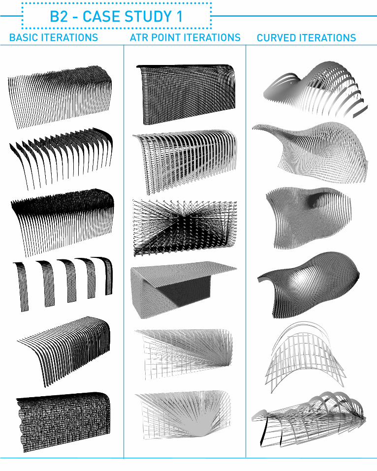
BASIC ITERATIONS ATR POINT ITERATIONS CURVED ITERATIONS
B2 - CASE STUDY 1

PAGE 19
TRIANGULATION ITERATIONS RANDOM ITERATIONS
PAGE 20
B2 - CASE STUDY 1
SELECTION CRITERIAThe brief for our tutorial suggests we need to create a ceiling decoration for a particular company so with that in mind my selection criteria will be as follows
1. A form that can be hung from the ceiling
2. Will remain structurally stable over time
3. Functions well as a piece of “art”.

PAGE 21
1. This was the one of the simpler iterations I made but I figured it was still interesting to look at. It made use of the rotate component to spin the pattern on the side to generate a different perspective. I feel like it could serve as a serviable albeit a tad bland decoration for a ceiling.
2. This uses the same patterning algorithim but combines it with a shift lists component. I divided the initial curved surface into hundred of points then sorted those lists in order to join them up with lines which I then extruded. Although it would likely look better turned upside down if this was actually to be made, I feel this design has an deeper level of complexity.
3. This iteration combines a voroni component with the previous patterning algorithm. By playing around with sliders to get a suitable pattern then lofting the lines to get the result shown to the left. It reminds me a little bit of a shell and the petals of a flower and at least personally to me is fairly nice to look at.
4. The final iteration was made using a different surface and an “attractor point” where all the lines will join up. The concept is rather simple but I am fairly pleased with how it turned out. The look with it’s grid-like lines makes it seem like there’s more then meets the eye.

PAGE 22
This is the Voussoir Cloud which is a landscape of vaults and columns which contains clusters of petals. It was designed for the South California Institute of Architecture in Los Angeles.
Each petal has it’s own seperate geometry which was developed by a computational script that calculates the curvature of each piece. The aim of the project was to break down the concept of structure and material to create a conflict between architectural typologies. They do this partly by using a light and porous material for the surface with compressive elements that gives the whole construct sensorial effects when it interacts with sunlight.
Breakdown of a petal
The design also draws from the works of engineers such as Frei Otoo and Antonio Gaudi who used hanging chain models to find efficient form. The structure and the material are meant to look confusing to the observer. The curvature of each petal as shown above is dependant on its adjacent voids. The initial computational script for this was designed in Rhino and used the proportional relationship of the tangent offset to sectional height. Each vault is also comprised of a Delaunay tessellation that confounds structural logics.
For now, I will be attempting to re-create this in Grasshopper, looking at two parts the geometry itself and the tabs/petals they made. Why this project in particular is interesting to me is that they are using the material performance of the material and it's physical properties to determine the final design and that seems particularly compelling as a method of design because it's based on a mathemathical logic.
B3 - CASE STUDY 2
VOUSSOIR CLOUD

PAGE 23
REVERSE ENGINEER
1.The first step to reverse engineering it is to simply use points then connect it to a Voronoi component to generate patterns.
2.The next part includes scaling the voronoi sections and moving them down so we can loft them with the original vorononi sections to create the “base” of the Voussoir Cloud.
3.Moving onwards we have to do a little bit of form finding. Basically we take the lofted surface and use grasshopper to weld the verticles and find “anchor points” so we can start running spring simulations on the surface now turned into a mesh. Using the Kangaroo physics engine applying forces to different parts of the mesh can be replicated.
4.Next we have to use break up our constucted mesh into deluanay mesh and triangulate it to create a grid of triangles which we will then use to create the petals.

PAGE 24
5.The final step is to re-create the tabs as you could see in the breakdown above. Using the tabs I created from the last step you can then offset the original mesh to create another set of tabs that is just slightly different from the original and connect these two using a Discontinuty component. To create the flap on the outside of the triangle that then folds upwards I tried the a cross product of the triangles with the Z axis and then finding the angle and connecting these all up with a simple line.
PROCESS DIAGRAM

PAGE 25
OUTCOMEOverall this exercise came in handy when it came to furthering my understanding of computational design. Namely I think the biggest thing I took away from trying to reverse enginneer this was just how interesting it is to see just how much complexity there in designs like this. They appear fairly simple at first glance but if you look at it, the scripting to figure out offsets, tangents, curvatures and material would take an incredible amount of work. As my reverse-engineered example is only to generate a similar form it's not even close to a fraction of the script needed to create the real deal.
One thing I didn’t quite nail down this time was expanding on the properties of the material used on Vousouir Cloud. I feel like this may be out of my capabilities at the moment and would probably also require me to have access to the material but it’s something else I found quite interesting as it seems like the compressive elements of the material used for the construct played a signifigant part in the end result. This is something worth looking into moving forward with the design as integrating the physical properties of a material into a design seems like an excellent way to generate unique forms.
Moving forward I like this idea of “vaults” that was shown here and for the interim project I’m looking to expand upon my definition and hopefully produce something that seems a bit more suitable for a ceiling decoration.

PAGE 26
BASIC ITERATIONS
#1Basic.
#2Negative force applied in Z direction.
#3Small amount of force applied with offset.
#4Positive force applied in the Z direction.
#5Adjusted stiffness.
#6Swapped connection points and negative force in Z direction.
B4 - DEVELOPMENT

PAGE 27
EXTRUSION ITERATIONS
#1Deconstruct mesh with extrusions.
#2Deconstruct different mesh with extrusions.
#3Deconstruct yet another mesh with extrusions.
#4Deconstruct mesh with oversized extrusions.
#6Generate 3D “rods” instead.
#5Swap circular extrusions for hexagons.
#8Use radial fields as extrusions.
#7Swap to hexagon grids.
PAGE 28
VORONOI ITERATIONS
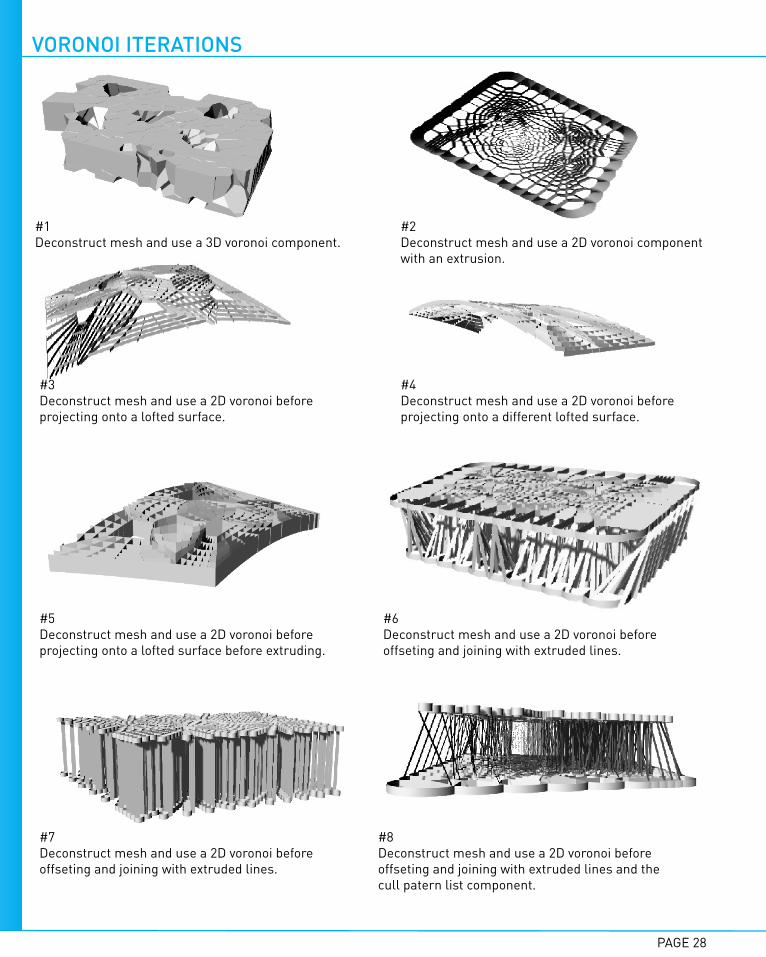
#1Deconstruct mesh and use a 3D voronoi component.
#2Deconstruct mesh and use a 2D voronoi componentwith an extrusion.
#3Deconstruct mesh and use a 2D voronoi before projecting onto a lofted surface.
#4Deconstruct mesh and use a 2D voronoi before projecting onto a different lofted surface.
#5Deconstruct mesh and use a 2D voronoi before projecting onto a lofted surface before extruding.
#6Deconstruct mesh and use a 2D voronoi before offseting and joining with extruded lines.
#7Deconstruct mesh and use a 2D voronoi before offseting and joining with extruded lines.
#8Deconstruct mesh and use a 2D voronoi before offseting and joining with extruded lines and the cull patern list component.

PAGE 29
MESH ITERATIONS
#1Extract mesh edges and extrude.
#2Extract mesh edges and extrude.
#3Deconstruct mesh and create lines from vertices.
#4Combination of deconstruct mesh with mesh edges and lines from verticles.
#5Combination of deconstruct mesh with mesh edges and lines from verticles.
#6Creating face circles from the mesh faces.
#7Creating face circles from the mesh faces then extruded.
#8Discontinuty with a line component using the tangents of the mesh vertices.
PAGE 30
MESH ITERATIONS 2
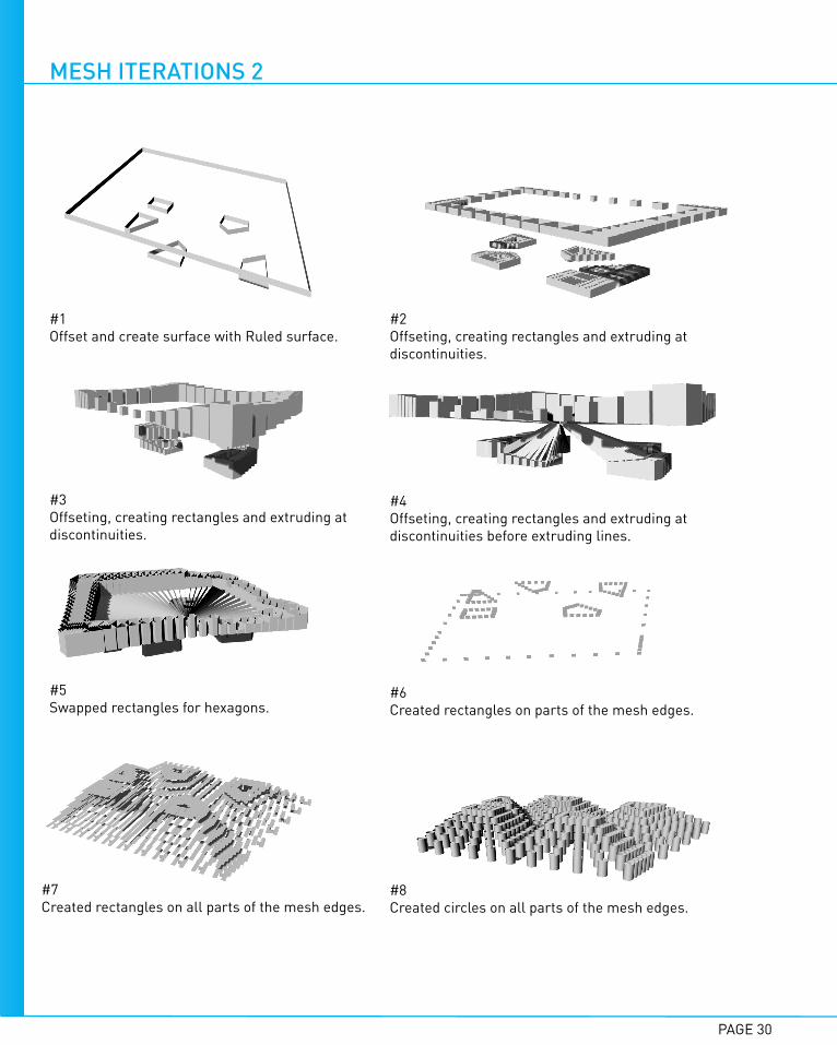
#1Offset and create surface with Ruled surface.
#2Offseting, creating rectangles and extruding at discontinuities.
#3Offseting, creating rectangles and extruding at discontinuities.
#4Offseting, creating rectangles and extruding at discontinuities before extruding lines.
#5Swapped rectangles for hexagons.
#6Created rectangles on parts of the mesh edges.
#7Created rectangles on all parts of the mesh edges.
#8Created circles on all parts of the mesh edges.

PAGE 31
SELECTION CRITERIAThe brief for our tutorial suggests we need to create a ceiling decoration for a particular company so with that in mind my selection criteria will be as follows
1. A form that can be hung from the ceiling
2. Will remain structurally stable over time
3. Functions well as a piece of “art”.
4. Now looking for something that utilizes vaults (Voussoir Cloud-style).
1. At this point I’m liking this idea of having these “vaults” as it gives the decoration a sense of volume. This was one of many attempts to try generate a interesting pattern along with that.
2. This was yet another one generated through playing around with mesh components and I think this one is probably one of the more successful variants because it seems structually sound and possible to fabricate. However I do think on a aesthetic level it’s very wonky and could be much improved.
3. Out of all the iterations I generated this one is a bit more interesting then most because I really like the way the circles overlap but with that being said it does seem very similar to other hanging ceiling decorations. Still the idea of weaving and overlapping is very interesting to me.

PAGE 32
The key ideas we ended up working around was having a system of vaults and lighting/shading effects. We all liked this idea of weaving and drooping veneer to create vaults.
We started by playing around with the Kangaroo plug-in to generate different types of meshes before settling on an prototype and laser-cutting some timber veneer strips.
IDEAS
B5 - PROTOTYPERESEARCH
VOUSSOIR CLOUDSEROUSSI PAVILIONOur interest here lay in the system of vaults that filled the room, like the previous precedent this also serves to create a sense of atmosphere through lighting and shading effects.
Areas of interest from this precedent was being able to find form through a simulation and the weaving of the strips was very appealing. The lighting and shading effects to create a sense of atmosphere was also quite compelling.
PAGE 33
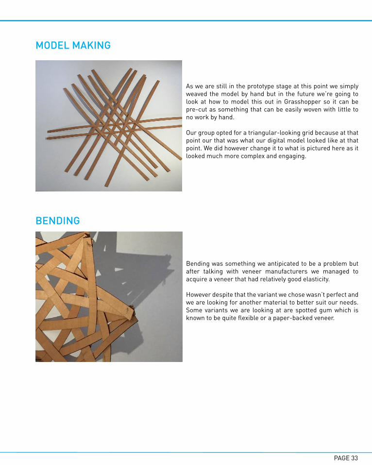
As we are still in the prototype stage at this point we simply weaved the model by hand but in the future we’re going to look at how to model this out in Grasshopper so it can be pre-cut as something that can be easily woven with little to no work by hand.
Our group opted for a triangular-looking grid because at that point our that was what our digital model looked like at that point. We did however change it to what is pictured here as it looked much more complex and engaging.
MODEL MAKING
BENDING
Bending was something we antipicated to be a problem but after talking with veneer manufacturers we managed to acquire a veneer that had relatively good elasticity.
However despite that the variant we chose wasn’t perfect and we are looking for another material to better suit our needs. Some variants we are looking at are spotted gum which is known to be quite flexible or a paper-backed veneer.

PAGE 34
As a group we settled on a design fairly early and the model-making shown in the previous stage helped us develop and advance it further. We decided we wanted a series of drooping vaults each made of intervoven veneer strips. They would be different sizes to create a sense of volume and complexity.
NETWORKThe group agreed on having a network of these vaults would look the best instead of just a single item but we’re still pondering how this network should work. Should the vaults intersect or be seperate like shown above? Will some vaults push up instead of drooping down. As we move in Part C of this studio, these are questions we will be addressing.
B6 - PROPOSAL
PROPOSAL
INNOVATIONAs of the time of the interim submission as a group we felt our innovation came from a two keys areas. The first was the use of a simulation to help with form generation which enables to the design to be based upon the mathemathical logic of physics. Secondly, the system of vaults helps provide the room with a sense of volume and space. As we progress to Part C we have to think of cost and constructability in more detail.

PAGE 35
The vault will open up to allow the projector to be mounted. While we are still in the planning stage at this point we are thinking the decoration should be mounted with rods or possibly utilizing some form of metal ring to hang it from a frame that can then let the decoration be easily moved (except the centre piece for the projector) in case any repairs need to be made.
SITE CONSIDERATIONS
One factor we considered very important was how this decoration would interact with lighting. One of our main precedents was the Voussoir Cloud which is very famous for the atmosphere it produces uses light porous material along with the voids to create interesting patterns. While we do want to replicate that to a certain degree we don’t want it to be intrusive. Moving forward we either want to
• Work out a way to mount the lights so it interacts with the decoration to create a good source of lighting.
• Pursue the idea of the decoration being movable (as mentioned earlier) so it can be moved depending on time of the day / lighting conditions.
• Expand on the idea of having a network and what types of different vaults we can have in the final design.
FURTHER CONSIDERATIONS

PAGE 36
As I progressed through Part B my understanding of Grasshopper improved and I picked up some of the basics of the very helpful Kangaroo plug-in. I’m starting to get an idea of where I want my design for this studio to end up but more importantly I think I now better realize the possibilities of designing while using Grasshopper as a tool.
The readings have touched on this a bit, how tools like Grasshopper are used to their full potential when man and machine are both working together. It’s not just a tool for a designer to use to generate ideas but also a way of exploring and improving designs that both you and the computer output. I feel like my fundamental understanding of Grasshopper is decent but there is still a long way to go. In particular my group and I found the digital modelling of our presentation quite challenging and as we contiune to do more research and watch more tutorials I feel we’ll be able to address some of the issues we are facing at the present time.
If I had to highlight a task that really stood out to me in my learning for Part B I’d say the reverse engineering and the susequent development were very helpful. It made me think of some of the issues you might run into while modelling and fabricating and how these issues may affect how the design turns out.
B7 - LEARNING OUTCOME

PAGE 37
EXAMPLE 1I chose this because this was generated almost on accident playing around with the series component when combined with a rotate component. Although not the most useful for a ceiling decoration I think it’s very hypotnizing and a great example of how Grasshopper can sometimes surprise you.
EXAMPLE 2This was one of my first uses of Kangaroo and interested me to keep exploring this idea of a hanging, droopy “vault-like” decoration.
EXAMPLE 3Just some of the learning I did in the tutorial videos provided to us by the tutors.
B8 - ALGORITHMIC SKETCHES

PAGE 38
1. Institute of Computational Design, ICD/ITKE Research Pavilion 2010, 2010 <http://icd.uni-stuttgart.de/?p=4458> [accessed 7 April 2016]2. Iwamoto Scott Architecture, 2008 <http://www.iwamotoscott.com/VOUSSOIR-CLOUD> [accessed 11 April 2016]3. “VOUSSOIR CLOUD - Iwamotoscott”, Iwamoto Scott Architecture, 2016 <http://www.iwamotoscott.com/VOUSSOIR-CLOUD> [accessed 10 April 2016]4. Iwamoto Scott Architecture, 2008 <http://www.iwamotoscott.com/filter/INSTALLATIONS/VOUSSOIR-SHELL> [accessed 11 April 2016]5. Voussoir Cloud Petals, 2013 <https://embodiedpotentials.wordpress.com/2013/04/22/coussoir-cloud-case-study/> [accessed 14 April 2016]
REFERENCES

PART C - DETAILED DESIGN

PAGE 40
RETHINKING AFTER FEEDBACKAfter the interim presentation and further feedback from our tutor my group and I decided we had a fair issues to address if we wanted to progress our design. Feedback to the actual aethestic of the proposal was quite positive from both ends but the biggest questions that remained were the construction of the decoration itself utilizing digital fabrication and also to figure out the a way that will let us lay out our network of vaults in a manner that befits a subject about digital fabrication.
At this point we had our a goal in mind but needed to more research to move the project away from a more generic arts project that was possible by hand towards something that relied on parametric design. In a sense our group was looking to find a working method of fabrication before we settled on a final concept.
C1 - DESIGN CONCEPT
FINALIZED CONCEPT
To create a ceiling decoration that uses a simulation to generate it's form whilst using strips to provide the room with sensorial effects through lighting and shading. The design will focus on being relatively easy to build with an emphasis on a low-key structural support system.
KEY CONCEPTS
1. Sensorial effects through shadowplay2. Low-key structural support system3. Ease of maintenance after construction4. Utilize a simulation for form-finding5. Layout the system of vaults using parametric tools.
PAGE 41
C2 - TECTONICS & PROTOTYPES
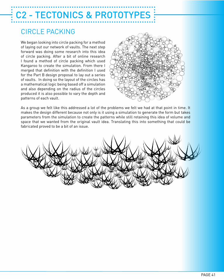
CIRCLE PACKINGWe began looking into circle packing for a method of laying out our network of vaults. The next step forward was doing some research into this idea of circle packing. After a bit of online research I found a method of circle packing which used Kangaroo to create the simulation. From there I merged that definition with the definition I used for the Part B design proposal to lay out a series of vaults. In doing so the layout of the circles has a mathematical logic being based off a simulation and also depending on the radius of the circles produced it is also possible to vary the depth and patterns of each vault.
As a group we felt like this addressed a lot of the problems we felt we had at that point in time. It makes the design different because not only is it using a simulation to generate the form but takes parameters from the simulation to create the patterns while still retaining this idea of volume and space that we wanted from the original vault idea. Translating this into something that could be fabricated proved to be a bit of an issue.
PAGE 42
PROTOTYPE 1
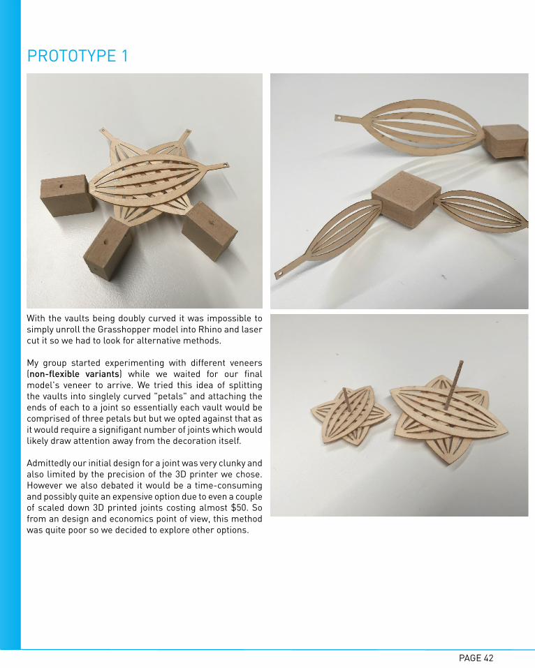
With the vaults being doubly curved it was impossible to simply unroll the Grasshopper model into Rhino and laser cut it so we had to look for alternative methods.
My group started experimenting with different veneers (non-flexible variants) while we waited for our final model's veneer to arrive. We tried this idea of splitting the vaults into singlely curved "petals" and attaching the ends of each to a joint so essentially each vault would be comprised of three petals but but we opted against that as it would require a signifigant number of joints which would likely draw attention away from the decoration itself.
Admittedly our initial design for a joint was very clunky and also limited by the precision of the 3D printer we chose. However we also debated it would be a time-consuming and possibly quite an expensive option due to even a couple of scaled down 3D printed joints costing almost $50. So from an design and economics point of view, this method was quite poor so we decided to explore other options.

PAGE 43
We tried another method of fabrication, this time using a ring system as shown above. We laser cut the petals and rings and put a small prototype together. Unfortunately we made the mistake of not seperating the petals of the vaults and due to the nature of the veneer we bought this was not successful.
The design however is indeed possible if we did seperate each vault into three petals like the idea on the previous page however after discussion this idea was also dropped.
After a discussion with our tutor it seemed like this method of construction was in some respects, too ugly. Once again this touches on the issue of the structural system for this decoration impeding on the design of the actual vaults. We wanted it to be low profile and this idea would not faciliate that.
Though a bit saddening, the circle packing idea seemed to be a bit unfeasible in the end in terms of ease of constructability while retaining the look we wanted. To make the best use of the time we had, my group moved away from this idea and decided instead to return to using Kangaroo with voronoi cells and surface splitting to generate the network of vaults we wanted. While it seems a waste the newer iteration proved to be a bit more flexible in the way we could adjust the vaults and much easier on the fabrication side.
PROTOTYPE 2
PAGE 44
JOINTS
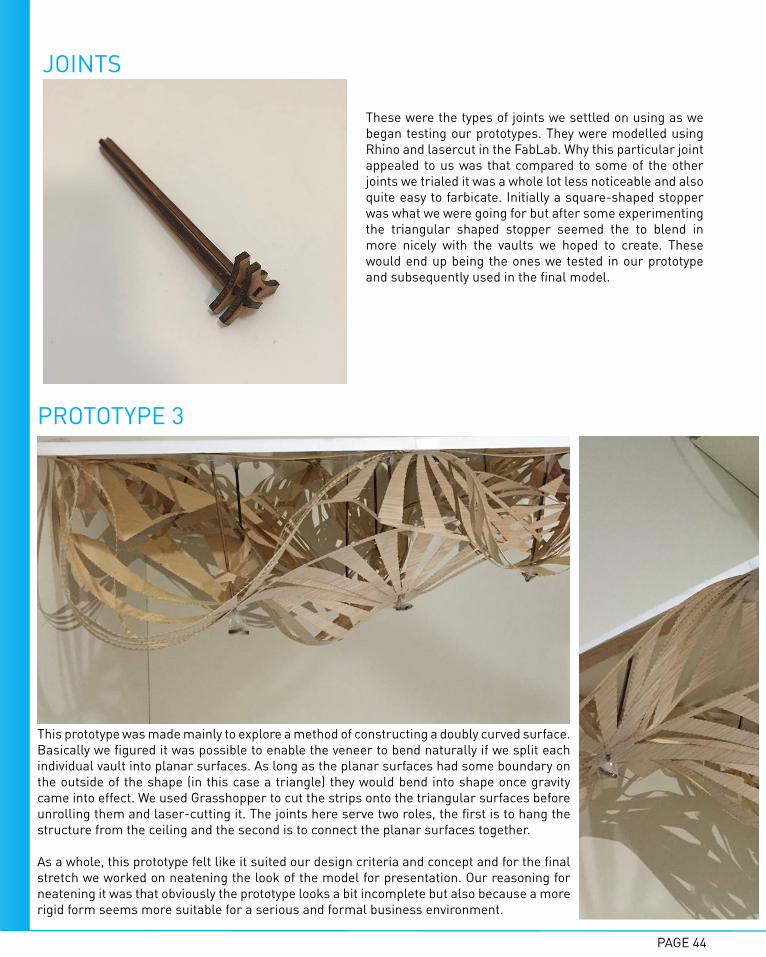
These were the types of joints we settled on using as we began testing our prototypes. They were modelled using Rhino and lasercut in the FabLab. Why this particular joint appealed to us was that compared to some of the other joints we trialed it was a whole lot less noticeable and also quite easy to farbicate. Initially a square-shaped stopper was what we were going for but after some experimenting the triangular shaped stopper seemed the to blend in more nicely with the vaults we hoped to create. These would end up being the ones we tested in our prototype and subsequently used in the final model.
PROTOTYPE 3
This prototype was made mainly to explore a method of constructing a doubly curved surface. Basically we figured it was possible to enable the veneer to bend naturally if we split each individual vault into planar surfaces. As long as the planar surfaces had some boundary on the outside of the shape (in this case a triangle) they would bend into shape once gravity came into effect. We used Grasshopper to cut the strips onto the triangular surfaces before unrolling them and laser-cutting it. The joints here serve two roles, the first is to hang the structure from the ceiling and the second is to connect the planar surfaces together.
As a whole, this prototype felt like it suited our design criteria and concept and for the final stretch we worked on neatening the look of the model for presentation. Our reasoning for neatening it was that obviously the prototype looks a bit incomplete but also because a more rigid form seems more suitable for a serious and formal business environment.
PAGE 45
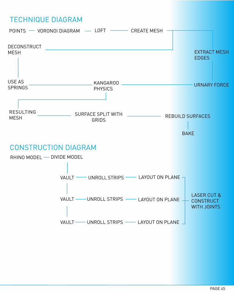
TECHNIQUE DIAGRAM
CONSTRUCTION DIAGRAMRHINO MODEL DIVIDE MODEL
VAULT
VAULT
VAULT
UNROLL STRIPS
UNROLL STRIPS
UNROLL STRIPS
LAYOUT ON PLANE
LAYOUT ON PLANE
LAYOUT ON PLANE
LASER CUT & CONSTRUCT WITH JOINTS
POINTS VORONOI DIAGRAM LOFT CREATE MESH
DECONSTRUCT MESH EXTRACT MESH
EDGES
USE AS SPRINGS URNARY FORCEKANGAROO
PHYSICS
RESULTING MESH
SURFACE SPLIT WITH GRIDS
REBUILD SURFACES
BAKE

PAGE 46
C3 - FINAL DESIGN MODEL
PERSPECTIVE ON-SITE The final design ensures that the vaults do not intrude upon the view of the project screen. By integrating lighting with the joints that hold up the decoration the effect of the shadowplay created by the strips is also decreased which may be more optimal. While creating a sense of atmosphere with the interaction of lighting and our design was important we also wanted to ensure it wouldn't be too intrusive as this is first and foremost a room for important meetings.
GRASSHOPPER FINAL MODEL
1. Kangaroo 2.1.4 Physics Plug-in2. Surface Splitting3. Voronoi4. Surface Grids
Areas of Grasshopper explored
PAGE 47
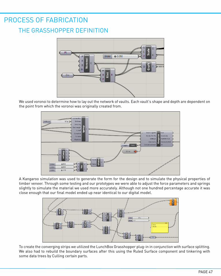
PROCESS OF FABRICATIONTHE GRASSHOPPER DEFINITION
We used voronoi to determine how to lay out the network of vaults. Each vault's shape and depth are dependent on the point from which the voronoi was originally created from.
A Kangaroo simulation was used to generate the form for the design and to simulate the physical properties of timber veneer. Through some testing and our prototypes we were able to adjust the force parameters and springs slightly to simulate the material we used more accurately. Although not one hundred percentage accurate it was close enough that our final model ended up near identical to our digital model.
To create the converging strips we utilized the LunchBox Grasshopper plug-in in conjunction with surface splitting. We also had to rebuild the boundary surfaces after this using the Ruled Surface component and tinkering with some data trees by Culling certain parts.
PAGE 48
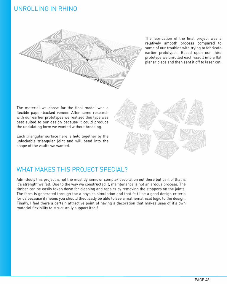
UNROLLING IN RHINO
The fabrication of the final project was a relatively smooth process compared to some of our troubles with trying to fabricate earlier prototypes. Based upon our third prototype we unrolled each vaault into a flat planar piece and then sent it off to laser cut.
The material we chose for the final model was a flexible paper-backed veneer. After some research with our earlier prototypes we realized this type was best suited to our design because it could produce the undulating form we wanted without breaking.
Each triangular surface here is held together by the unlockable triangular joint and will bend into the shape of the vaults we wanted.
WHAT MAKES THIS PROJECT SPECIAL?Admittedly this project is not the most dynamic or complex decoration out there but part of that is it's strength we felt. Due to the way we constructed it, maintenance is not an ardous process. The timber can be easily taken down for cleaning and repairs by removing the stoppers on the joints. The form is generated through the a physics simulation and that felt like a good design criteria for us because it means you should theotically be able to see a mathemathical logic to the design. Finally, I feel there a certain attractive point of having a decoration that makes uses of it's own material flexibility to structurally support itself.

PAGE 49
FINAL MODEL
1:1 SCALE
1:10 SCALE

PAGE 50
During the final presentation the feedback was generally that the 1:10 model was more compelling then the 1:1 model. What this kind of suggest to me is that like circle packing our design works a lot better then employing many of these vaults rather then just a few. Another area of critique was that overlaying the module on top of one another would create a greater sense of volume. A big concern was on the supporting system for the edges of decoration and how they would fare in time. General reception to the shadowplay elements and overall look of the decoration was fairly positive.
So as a whole, while I'm a little upset we ended up having to forgo the circle packing idea I think for the most part we acheived what we set out to do which was create a design that investigated the material performance of timber veneer and utilized strips and folding. Looking back I do believe there could've been more time spent into adding complexity to the Grasshopper definition but because we suffered from some issues fabricating and developing prototypes time became a factor that worked against us.
Still overall as a whole this subject has been a real treat. It really opened my eyes to the power of computation when it came to design and what could be acheived through programs like Grasshopper. Personally, I really enjoyed creating scripts then altering variables to change how it looked. In a sense this ties back to the idea that both man and machine can be the designers. I think that idea is something to take into account for the future, especially as parametric design becomes more accepted. In the future, I think computational design will most certainly be something I try out in my designs.
C4 - LEARNING OUTCOME

PAGE 51
1. Thorp, Jer, Circle Packing Artifacts, 2009 <https://www.flickr.com/photos/blprnt/4217986276> [accessed 21 May 2016]
REFERENCES