Studies on PVC Blends with Special Reference to PVC/CR and PVC/LLDPE Blends
235
STUDIES ON PVC BLENDS WITH SPECIAL REFERENCE TO PVC/CR AND PVC/LLDPE BLENDS A thesis submitted by JAVAMMA FRANCIS in partial fulfilment of the requirements for the degree of DOCTOR OF PHILOSOPHY OF THE COCHIN UNIVERSITY OF SCIENCE AND TECHNOLOGY DEPARTMENT OF POLYMER SCIENCE & RUBBER TECHNOLOGY COCHIN UNIVERSITY OF SCIENCE AND TECHNOLOGY COCHIN - 682 022 MARCH 1992
Transcript of Studies on PVC Blends with Special Reference to PVC/CR and PVC/LLDPE Blends

STUDIES ON PVC BLENDS WITH SPECIAL REFERENCE TO PVC/CR AND PVC/LLDPE BLENDS
A thesis submitted by
JAVAMMA FRANCIS
in partial fulfilment of the
requirements for the degree of
DOCTOR OF PHILOSOPHY
OF
THE COCHIN UNIVERSITY OF SCIENCE AND TECHNOLOGY
DEPARTMENT OF POLYMER SCIENCE & RUBBER TECHNOLOGY
COCHIN UNIVERSITY OF SCIENCE AND TECHNOLOGY
COCHIN - 682 022
MARCH 1992

CERTIFICATE
This is to certify that this thesis is a report
of the original work carried out by Miss Jayamma Francis
under my supervision and guidance in the Department of
Polymer Science and Rubber Technology, Cochin University
of Science and Technology. No part of the work reported
in this thesis has been presented for any other degree
from any other institution.
Kochi 682022
25 March 1992
-~~ Dr.R.E. George (Supervising Teacher) Reader, Dept. of Polymer Science and Rubber Technology Cochin University of Science and Technology
DECLARATION
I hereby declare that the thesis entitled "STUDIES ON
PVC BLENDS WITH SPECIAL REFERENCE TO PVC/CR AND
PVC/LLDPE BLENDS" is the original work carried out by me under
the supervision of Dr.K.E. George, Reader, Department of Polymer
Science and Rubber Technology, Cochin University of Science and
Technology, Cochin 682022, and no part of this thesis has been
presented for any other degree from any other institution.
Kochi 682022
25 March 1992
fol nC Is '" ~ il
j~-~
JAYAMMA FRANCIS

ACKNOWLEDGEMENTS
I wish to place on record my deep sense of gratitude to
Dr.K.E. George, Reader, Department of Polymer Science and Rubber
Technology, Cochin University of Science and Technology for suggesting the
problem and for his inspiring guidance throughout the course of this work.
Prof.D. Joseph Francis, Head of the Department of Polymer
Science and Rubber Technology, and other faculty members of the
Department have been keenly interested in this investigation and I gratefully
acknowledge the valuable suggestions given by them. I also thank all the
members of the non-teaching staff of the Department for their timely help.
I gratefully acknowledge the help rendered by my friends and
colleagues during the course of this investigation. I record my thanks to
Mr.K.P. Sibiraj for neatly typing the thesis and to Mr.CJ. Soman for the help
in the preparation of the figures.
JAYAMMA FRANCIS.

Chapter 1
Chapter 2
Chapter 3
Chapter q
Chapter 5
CONTENTS
INTRODUCTION
EXPERIMENTAL TECHNIQUES
STUDIES ON POLY{VINYL CHLORIDE)!
ELASTOMER BLENDS
STUDIES ON POLY{VINYL CHLORIDE)!
Pages
1
36
68
LINEAR LOW DENSITY POLYETHYLENE BLENDS lq3
SUMMARY AND CONCLUSIONS 216
LIST OF PUBLICATIONS FROM THIS WORK 221
* * *

Polymers
PVC
PE
LDPE
LLDPE
HDPE
PP
PS
PMMA
ABS
MBS
EVA
ePE
SBS
SIS
SEBS
SAN
POM
NR
NBR
SBR
ESEBS
LIST OF ABBREVIATIONS USED IN THIS THESIS
Poly(vinyl chloride)
Polyethylene
Low density polyethylene
Linear Jow density polyethylene
High density polyeth ylen e
PolypropyJen e
Polystyren e
Poly(methyl methacrylate)
Acrylonitrile-butadien e-styren e
Methyl methacrylate-butadiene-styrene
Ethylene-vinyl acetate
Chlorinated polyethylene
Styrene-butadiene-styrene
Styrene·iso pren e·styren e
Styrene-ethylene·butylene-styrene
Styren e-acrylonitrile
Poly(oxy methylene)
Natural rubber
Acrylonitrile·butadiene rubber
Styrene-butadiene rubber
Epo xidised stYTen e-eth ylene-butylene-styren e
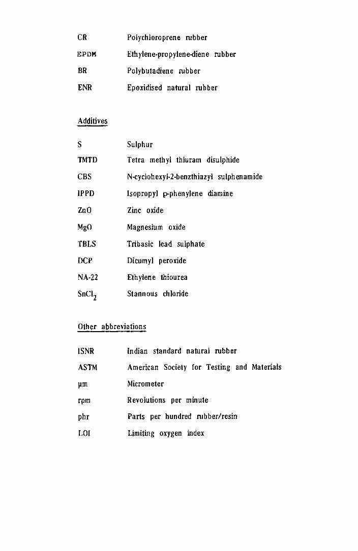
CR Polychloroprene rubber
EPDM Ethylene-propyleoe-diene rubber
BR Polybutadiene rubber
ENR Epoxidised natural rubber
Additives
S
TMTD
CBS
IPPD
ZoO
MgO
TBLS
DCP
NA-22
SnCl2
Sulphur
Tetra meth yl thiuram disulphide
N-cyclohexyl-2-b enzthiazyl sulph enamide
Isopropyl p-phenylene diamine
Zinc oxide
Magnesium oxide
Tribasic lead sulphate
Dicumyl peroxide
Ethylene thiourea
Stannous chloride
Other abbreviations
ISNR Indian standard natural rubber
ASTM American Society for Testing and Materials
}lm Micrometer
rpm Revolutions per minute
phr Parts per hundred rubber/resin
LOI Limiting oxygen index

Tg
T
o
ML(l+4) at IOO"C
MFI
l lIIapp
l'wapp
tw r w
Q
n
E
R
Glass transition temperature
Temperature
Solubility parameter
Volume fraction
Mooney viscosity determined using large rotor after a dwell time of one minute and rotor run of 4 minutes at 100°C.
Melt flow index
Free energy change of mixing
Enthalpy change of mixing
Entropy change of mixing
Internal energy change of mixing
Viscosity
Apparent shear stress at the wall
Ap parent sh ear rate at th e wall
True shear stress at the wall
True shear rate at the wall
Pressure drop
Entrance pressure loss
Length of capillary die
Radius of the capillary die
Volumetric flow rate
Power law index
Activation energy
Gas constant

De Diameter of the extrudate
D Diameter of the capillary die
YR Recoverable shear strain
M Torque
S Revolutions per minute of the Brabender rotor
Mg Meter gram
Mrad Mega rad
MPa Mega Pascal
IR Infra red
K Consiste.ncy index
Nm Newton meter

Chapter I
INTRODUCTION

INTRODUCTION
Development of new molecules and chemical
modi f ica t ions of ex is t i ng ones have been the mos t common
ways of facing new challenges for polymeric materials.
These routes have become increasingly complex and
expensive over the years and thus alternative ones have
become more interesting and attractive. Polymer blending
is one such approach that is presently in a state of rapid
scientific and commercial development. The reduced
probability of finding new, inexpensive and wide utility
homopolymers led to the blending technology as one of the
fastest growing segments of polymer technology. The
increasing range of application makes polymer blending
more . 1-6 attractlve. The rapid development
commercialisation of polymer blends is due to their
quick modification of performance,
higher performance at reasonable price,
and
ability to extend the performance of expensive resins
and potential for recycling of plastic wastes.
BASIC THEORY OF BLENDING
A successful polymer blend is a cost effective
mixture of two or more polymers with a better combination
1

2
of different properties. Depending upon the polymer
miscibility, the blends can be classified as miscible,
partially miscible and immiscible, or in a technological
sense as compatible, semicompatible and incompatible. An
ideal blend is one which is homogeneous and behaves like a
single component system. A large number of compatible
polymer blends and alloys have been investigated and
f 11 . l' d 5-9 success u y commerCIa Ise . Alloys are a class of
polymer blends in which a large interpenetration of
domains is secured by physical and/or chemical means.
Although the terms alloys and blends are often used
synonymously, they differ in the level of thermodynamic
compatibilities and resulting properties. On the high end
of the compatibility spectrum are the alloys. Alloys give
a tighter, denser molecular structure than blends.
The structure and stability of polymer blends
depends primarily on the miscibility of polymers used in
its preparation. Miscibility is governed by the Gibbs
free energy of mixing (nG ). m
The thermodynamic condition
for obtaining miscible blend IS that the free energy of
mixing must be negative
Cl G = A H - T 63 m m m

3
where AHm is the change in enthalpy) 6S m
the change
in ent ropy upon mi xi ng and T, the absol ut e temperature.
Since the entropy term IS negligible for polymers, the
heat of mixing AH IS the key factor deciding the m
pdlymer-polymer miscibility. In the caSe of purely
dispersive forces.oH is always positive. m
Consequently,
high molecular weight systems with this type of
interaction are rarely miscible. Miscibility drops
significantly with growing chain length. If however, there
exist so called specific interactions (ion-dipole
interactions, hydrogen bonds) between the components, then
~H can be negative and the polymers can become miscible. m
Or, in otherwords, miscibility depends upon the degrees of
7-14 interaction among the polymer components. From the
standpoint of selecting polymer blends, a quantitative
means of predicting the affinities of polymer pairs in
terms of easily measured properties of the components
would be desirable. One possibility is through the use of
solubility parameter b, which has proved useful in the
study of the dissolution and swelling of polymers in low
molecular weight liquids.IS
Compilation of the solubility
parameters of the polymers is available.16
For nonpolar
liquids the internal energy change upon solution is given
by ~E = of solution) where are
4
volume fractions of the components. Realising that
amorphous polymers a re essent i a 11 y 1 iqu ids a nd assuming
that the volume change upon mixing is negligible this is
an expression for the change in enthalp;'.. on solution
since AE = 4H for constant volume, constant pressure
process. This equation always results in a positive AH,
indicating that for nonpolar high polymers, where the T6S
term is small, true solution will not occur unless the (, s
are almost perfectly matched.
Most of the polymer pairs are thermodynamically
unfavourable to form homogeneous mixtures and mixing them
leads to multiphase systems. Inorder to achieve a
homogeneous or a compatible blend, it is necessary to
choose polymer components capable of specific interactions
among them leading to negative heats of mixing.
The usual
measurement of glass
miscibility criterion
transition temperature T • g
is the
Miscible
polymers are considered to be those which give a blend
with a single glass transition temperature dependent on
the composition of the blend. Polymers, which in a blend,
exhibit two or more T s, corresponding to the glass g
transition temperatures of the individual components are
od d bOO °bl 10,17 conSl ere to e lmmlSCl e.

5
METHODS OF PRODUCING POLYMER BLENDS
The simplest and most direct method is
mechanical blending. This may be accomplished on two roll
mill or in internal mix(/.ys ,eg., Banbury. The nature of
the resulting dispersion depends on the length of mixing,
the shear field in equipment, temperature, rheological
properties of the component polymers etc. Also there is a
possibility of chemical effects produced by the milling
operation.
When the individual components can be obtained
in latex form, they may be conveniently combined by
blending the latices. The polymer is then recovered by
coagulation or spray drying. This method results in an
intimate, uniform dispersion. However, one drawback is
the difficulty in completely removing the nonpolymer
material (emulsifier etc.) present in the latices.
Mixing of polymer solutions is in practice
mainly used for coatings, because it allows rapid and easy
mixing of the components at low energy costs, leads to
simple applications at normal temperatures and neither
causes degradative colour changes nor premature

6
crosslinking reactions. But, for the preparation of the
solid polymer blends, this method requires removal of the
solvent, which usually leads to phase separation.
Furthermore)the use of solvents implies problems connected
with their price, toxicity, flammability, pollution and
the economics of the whole process. Usually only
laboratory samples of solid polymer blends are prepared by
this method.
Blends may also be prepared by dissolving a
polymer in the monomer of the other component and then
polymerising the second component. This may result in
appreciable grafting of the polymer in addition to good
dispersion.
PROPERTIES OF POLYMER BLENDS
A wide range of properties can be achieved by
blending which includes mechanical, electrical and
chemical properties along with processability. Compati-
bility is the fundamental property deciding the practical
'l't f 1 bl d 1,11,18 1 bl d b ut 1 1 Y 0 a po ymer en. Po ymer en scan e
described by the following equation:

7
where P is the property value of the blend, PI and P2
the
propert i es 0 f the isola t ed component sand Cl and C2
the
respective concentrations of the constituents. I is a
term for the system which defines the level of synergism
created by the combination of the two components.
For I > 0 the property is synergistic
I = 0 the property is additive
I < 0 the property is nonsynergistic.
The most important factor governing the ultimate
properties of a polymer blend is the intermolecular
bonding force between the molecules. The low interaction
at the interface is responsible for its tendency towards
phase sepa ra t ion under va r ious condi t ions (st ress , blend
rat i 0 and temperat ure) • The poor adhesion between the
molecules at the interface in a heterogeneous system does
not allow efficient transfer of stress across the
interface leading to premature failure under stress.
Though many immiscible systems form useful products and
are being successfully commercialised, the applicability
of polymer blends is limited because of the inferior
macroscopic properties. Modification of incompatible
polymer systems for developing useful materials has
become an active field of research both in the industrial
and academic level.

8
INTERFACE MODIFICATION IN POLYMER BLENDS
The performance of a polymer blend is dependent
upon the st rength of the inter face. It is possible to
make a polymer blend compatible so that the resultant
properties may be more synergestic and the blend becomes
more homogeneous. Modi f i ca t i on of po I ymer bl end can be
achieved by a variety of ways.18,19
By Addition of a Polymeric Compatibiliser
The incorporation of block, graft or random
copolymers whose chemical structures are identical with
the blend components IS
Such compatibilisers are
actions with each of the
found to promote miscibility.
able
blend
to make specific
20-24 components.
inter-
Di or
triblock copolymers of styrene and butadiene have been
found to be more useful in this way to act as interfacial
agents in blends of polyolefine/polystyrene (PS) mixtures.
Diblocks are more efficient interfacial agents than
triblock or graft 25-27 copolymers. Ethylene-propylene-
diene rubber (EPDM) and poly (methyl methacrylate) (PMMA)
can be made more or less compatible by adding EPDM-g-MMA
28 copolymer. The compatibilising or emulsifying action of
certain solid phase dispersants in poly (vinyl chloride)
(PVC)/Polyethylene (PE) and PVC/PS blends has been

9
reported . 29-34 earl1er. Boutevin et al. 35 investigated
P(E-g-MMA) copolymers as a compatibiliser to low density
polyethylene (LDPE)/PVC blends. They found values of
tensile strength to be almost double compared to those of
homopolymer mixtures. Statistical copolymers have also
been found to be useful to a limited extent as in the case
of ethylene-propylene rubber compatibilising polypropylene
(pp) and high density polyethylene (HDPE).36-39 The
compatibilisers can be either added separately or may be
formed in situ during blending.
Compatibilising action of a block or graft copolymer

10
By Blending Functionalised Polymers
Chemical modification of polymers is a common
means of improving properties of the polymer blends.
Blending of polymers containing carboxyl and epoxy groups
has been reported as a promising way to promote inter-
. 18,40-42 faclal strength. The reactive blending of such
functionalised polymers is followed by the in situ
formation of compatibilising interchain polymers.
Carboxyl terminated butadiene/acrylonitrile rubber (NBR)
has been utilised for the successful blending with
epoxies. Polypropylene can be functionalised to link with
f . l' d d' 1 .. 21 unctlona lse NBR urlng me t mlxlng. As a result,
improved ultimate properties are achieved by making the
polymer blend less incompatible.
By Addition of LoW Molecular Weight Materials
A veriety of low molecular weight chemicals can
also act as modifiers or compatibilisers through reactions
such as grafting, crosslinking, co-crosslinking etc.
Recently/grafting of maleic anhydride on LDPE followed by
bl d · .. h ,. db' 1 41 en lng Wlt PS was lnvestlgate y L1U et a. as a
possible means for improving the compatibility. The
addition of some polyfunctional monomers in presence of
perox idewas reported to be effective in blends of PVC

11
with 43,44
pol ye.thy 1 ene. Mori and Nakamura studied the
effect of co-crosslinking by triazine trithiols on the
property modification
Examples of the class
PVC/EPDM.
for a series of
include PVC/NBR,
bl d 45-47 en s.
PVC/CR and
The continuous nature of the phases as a result
of such interface modifications leads to efficient
force/stress transfer between the component phases.
PVC BASED POLYMER BLENDS
Poly (vinyl chloride) (Pvc) is a versatile
polymer, used in flexible, semirigid and rigid forms.
In world wide plastic production it is second only
to polyolefines. The rapid expansion and consump-
tion of pvc is due to lower cost, greater avail-
ability, good mechanical properties and diversity of its
. 48-50 propertIes. It is mainly produced by the polymerisa-
tion of vinyl chloride by suspension method. The
structure of pvc is,
CH} I n Cl

12
Although PVC has many desirable properties, it
has two shortcomings in commercial applications: poor
processabi 1 i t y and poor impact st rength. Common ways of
overcoming poor processability are to mix with plasti-
c i zers or to increase the process ing temperature. There
are associated disadvantages since by the former method,
it is not possible to obtain high impact strength
because of antiplasticizing effect and by the latter
method there is a risk of thermal degradation. Also low
molecular weight plasticizers of PVC have a tendency to
leach out on ageing. These problems can be solved
successfully by the addition of small amounts of polymeric
modifiers/plasticizers to yield polymer bl d 51-53
en s.
Hence polymeric plasticizers like chlorinated polyethylene
(CPE), ethylene-vinyl acetate ( EV A) , acrylonitrile-
butadiene rubber (NBR), polyether-ester block copolymer
d 54-57
(Hytrel) etc. are being use. PVC behaves generally
as an electron acceptor and thus should interact strongly
wi th electron donors. In fact, it is said that of all
polymers studied to date, PVC is the most miscible with
structurally different homopolymers and copolymers. A lot
of work has been done on the compat ibi 1 i t Y of PVC wi th
. l' 1 t" 58,59 varIOUS po ymerIc p as ICIzers. Combining nonpolar
elastomers with PVC is one of the promising methods of
13
increasing the oil, petrol and fire resistance of the
vulcanizates based on them. 60 Majority of the PVC systems
show multiphase behaviour. Yet, they are used in several
applications. The mechanical propert ies of such blends
are far inferior to those expected. This is probably due
to the low level of compatibility between the polymers and
also the insufficient fusion characteristics of PVC
particles. Deak et al.61
studied the effect of small
quantities of additives on the properties of rigid PVC and
PVC modified with other polymers.
BLENDS OF ELASTOMERS WITH PVC
One of the most prominent needs for PVC in
application end use is permanent plasticization. A very
important and commercially significant blend is that of
NBR and Pvc. 62 - 65 NBR acts as a permanent plasticizer for
PVC and at the same time PVC improves the ozone, thermal
ageing and chemical resistance of NBR. PVC/NBR blends are
used in applications such as wire and cable inSUlation,
O-rings and oil seals, printing roll covers, gaskets, fuel
hose covers, shoe soles, anti static floor tiles etc. The
amount and type of vulcanising system has a great effect
on the properties of the blends. The effect of non-
con ven t iona 1 vul can i si ng syst em for property mod if ica t ion
14
of PVC/NBR blends was investigated. P-nitrosophenyl
amine plays the role of a modifier and aids the vulcanisa
tion of the blend in presence of sulphur (S) and TMTD.66
More recently modification of NBR/PVC blends was studied
us i ng na t ura I rubber (NR), pol ybutad i ene rubber (BR) and
styrene-butadiene rubber (SBR).67 Co-crosslinking is
found to be an effective means of improving the mechanical
properties 6f the blends. Triazine trithiols can be used
effectively as a co-crosslinking agent for PVC/CR, PVC/NBR
and PVC/EPDM blends. 45 - 47 Blending of SBR with PVC
results in a marked improvement in the impact strength of
pvc. 68 The effect of addition of a third component on the
mechanical properties, compatibility and morphologies of
h bl d . th SBR d . t' d 69 t e PVC en s Wl an BR was lnves 19ate • NBR is
found to be a good compatibiliser for PVC/SBR and PVC/BR
blends. Propert i es 0 f PVC/EPDM bl ends mod i f i ed wit h CPE
I · , d 70 were a so lnvestlgate • The mechanical, rheological and
morphological studies of PVC/Epoxidised natural rubber
( ENR) ha ve shown tha t higher levels 0 f epox ida t i on makes
b 'bl . h 71,72 NR to e more compat 1 e Wl t PVC. Mixing with PVC
is found to be an effective method for the property
modification and
speciality rubbers
rubber (CR).73,74
cost
like
reduction of high priced
polysulphide and chloroprene

15
BLENDS OF OTHER PLASTICS WITH PVC
The impact resistance of PVC can also be
improved by introduction of polymeric modifiers in
particular acrylonitrile-butadiene-styrene (ABS) or methyl
methacrylate-butadiene-styrene (MBS) plastics. The
toughness and processability of ABS combines with the
flame resistance of PVC in PVC/ASS blends. The misci-
bility of the system depends upon the acrylonitrile
content in ABS. PVC/ABS and PVC/MBS blends are noted for
their good dimensional stability. PVC/ABS blends have
been utilised for interior truck panels, communication
relays, electrical housings, appliance housings,
1 ., h' 75 te ev~s~on ous~ngs etc. The impact modification of PVC
by CPE has been reported earlier. CPE also acts as a
permanent 1 .' f 76 P ast~c~zer or PVC. Recently, compatibilisa-
tion of PVC/CPE blends with epoxidised NR has been studied
by Stathis and 77 coworkers. The effectiveness of
epoxidised hydrocarbons to produce compatible polymers
were reported by several research 33 groups. Epoxidised
SBS was found to be a typical example for improving the
compatibility of PVC/PS systems. PVC/PMMA blends combine
the heat resistance of PMMA with chemical and flame
resistance of PVC in some 1, , 78
app ~catlons. The main

16
application of this blend is in mass transit vehicles.
Paul and 79 Barlow studied the miscibility behaviour of
PVC/styrene-acrylonitrile (SAN) copolymers. NBR is found
to be useful for the compatibilisation of poly vinylidene-
fluoride co-vinyl chloride/PVC blends. The effect of some
solid phase dispersants on the mechanical performance of
the immi sci bl e PVC/PE bl ends was st ud i ed as a means for
reutilisation of these . 29 32 80 plastIc wastes. ' , Function-
alised polyolefine/PVC blends are used for the development
of low halogen and non-halogen, fire resistant, low smoke
81 cable sheathing compound. PVC/PE combinations are also
used for the preparation of thermofoamable blisters. 82
Mixtures of acrylic terpolymer with PVC are used for
preparing adhesive sealent compositions with improved
properties and enhanced outdoor . 83
resIstance. The
processability of PVC can be improved by the addition of
EVA, CPE, Hytrel etc. 54 - 57 ,84
COMMERCIAL PVC BLENDS
Mixing of PVC with various types of polar and
non-polar polymers changes the properties of PVC, so
significantly that the applicatl.on spectrum of this
polymer is continuously increasing. The commercially
important blends of PVC and their properties are given in
1 Table 1.1.

No. Additive
1. ABS; MBS
2. Acrylics
3. Poly(caprolactone)
4. SAN
5. Poly(imide)
6. Poly(urethanes)
7. Nitrile rubber
8. EVA
9. Chlorinated PE
17
Table 1.1
Improved property
Impact
tensile
resistance,
strength,
temperature.
hardness,
distortion
Impact resistance, transparency,
chemical resistance, oil resist
ance, mouldability.
Plasticization,
impact resistance.
mouldability,
Low temperature toughness, pro
cessability, dimensional stability.
Transparency, high distortion
temperature, impact resistance.
Plasticization, tensile strength,
impact resistance, low temperature
toughness.
Plasticization, toughness.
PI as t i ci za t ion, toughness, adhesive
ness.
Processability.
10. Poly(vinyl chloride
g-ethyl-acrylate)
11. PE + CPE
12. PS
13. Hytrel
14. PVC/EVA copolymer
IS. Chlorinated POM
FUSION OF RIGID PVC
18
Impact resistance, thermal stabi
lity, processability.
Ductility, elongation, low temper
ature toughness
Toughness, weatherability.
Low temperature·
plasticization.
Processability,
mechanical properties.
toughness,
Processability, plasticization.
PVC differs from other widely used plastics like
PE, PS, PP in that the polymer has a distinct structure.
Suspension PVC consists of grains of about 100 pm size.
Inside these grains, smaller primary particles of about
1 pm size are found partly agglomerated to larger units.
This hierarchial structure of PVC has to be destroyed in
order to get a thermoplastic melt necessary for processing
rigid PVC. 8S Fusion involves the loss of identity of
grains and primary particles of PVC which is highly
dependant upon both shear and thermal history of PVC.

19
Fusion mechanism of PVC
The processing behaviour and end use properties of PVC are
. 85-89 strongly influenced by the degree of fuslon.
RHEOLOGY OF PVC BLENDS
The rheo1ogical properties of polymer melts have
been studied extensively over the past decade. These
studies have concentrated on pure polymer systems.
Recent 1 Y rheolog i cal prope rt i es of pol ymer mi x t ures are
also being studied due to the great practical use of such
mixtures. Investigation of the rheological properties of

20
the mixtures will make it possible to assess their
behaviour during manufacture into article. Moreover, the
rheological properties
into the structure of
of mixtures help gaining insight
89-91 pol ymer mel t s. In regard to
two phase flow of molten polymers, rheology should clearly
be known to rationally design processing devices and to
smoothly operate equipmen~which handle two phase systems.
One of the most fundamental requirements is to determine
the rheological properties of a given two phase system in
terms of viscosities and elasticities of individual
components, composition ratio and melt temperature.
Rheology 0 f PVC bl ends is pa rt i cular 1 y importan t due to
the fusion behaviour of Pvc.90
-93
The mechanical strength
of PVC blends is critically dependant upon the fusion
state of PVC and hence study of the processing character-
istics of PVC blends is of great importance.
OBJECTIVES AND SCOPE OF THE PRESENT WORK
The present investigation 1S mainly on PVC
blends. PVC resins surpass every class of polymers in
world wide commercial importance, both in diversity of
applications and in total tonnage of finished products.
The factors responsible for PVC's number one position
are low cost and ability to be compounded into various

21
flexible and rigid forms with good physical, chemical and
weathering propert ies. In addition, PVC has broad
processability including calendering, extrusion, moulding
(injection, compression, rotational, blow) fluid (solution,
latex, organosol, plastisol) coating and impregnation. 64
PVC formula t ions conta i n va ry i ng amount s of the
following ingradients in order to give the polymer the
desired processing and end use characteristics.
Plasticizers
Polymeric modifiers
Fillers
Heat stabilisers
Lubricants
Colourants
Light stabilisers
Blowing agents
Flame retardants.
The present study is mainly in the area of solid
polymeric modifiers for PVC.
is on PVC/Elastomer blends.
The first part of the study
Polymeric modifiers can be
classified into four categories: those that plasticize,
increase impact strength, increase heat distortion
temperature and improve processability. The property
modification is highly dependent upon the miscibility of

22
the modifying polymer with pvc. By far the wide range of
polymeric modifiers for pvc fall into the broad category
that can be classified as partially miscible. A broad
range of properties may be obtained depending upon the
degree of miscibility. These polymers can increase the
rate of fusion of PVC powder leading to a more rapid
formation of a homogeneous melt having higher melt
strength. The. present study on the blends of PVC with
elastomers was undertaken with a dual purpose of improving
the fusion behaviour and melt strength of PVC along with
imparting special properties to the elastomers. Effect of
compatibilizers in improving the mechanical and processing
behaviour of PVC/Elastomer blends is a major part of the
study.
The second part of the study is on PVC/Linear
low dens i ty pal yethylene (LLDPE) blends. The study was
selected mainly as a possible means of reprocessing mixed
scrap or waste plastics, since pvc and polyethylene form a
94 sizable fraction of such wastes. Their lack of bio-
degradability is generating new problems owing to their
large space requirements and the possible damage to the
environment by the various materials contained in them.
The best solution to reducing waste, according to many

23
scientists, is a combination that includes bio-degradable
plastics and plastic recycling. However, by 2002 bio-
degradable plastics are expected to account for only three
per cent of all plastic packaging waste and hence there is
very good scope for pol ymer recycl i ng in the years to
come.
Recycling by reprocessing of plastic waste is a
major solution to the 31,80
problem. However, blends of
mixed scrap or waste plastics usually have very poor
ductility and toughness, a situation which renders their
practical use difficul t. Th is probl em genera 11 y exists
because the ingradients of most polymer blends are
grossily incompatible and separate into individual phases.
Application of mechanical stress usually results in
interfacial f "l 2,4,7 a~ ure. It has been shown that
mechanical properties of the blends of incompatible
polymers can be significantly improved by addition of
agents which improve interfacial adhesion. The most
common compatibilisers are block, graft or random
copolymers, co-solubilisers enhancing interpenetration of
resin domains, co-reactants or catalysts enhancing
chemical reaction between the resins and modifiers or
additives enhancing the specific " "1 InteractIons.

24
Co-crosslinking of the polymers is also a special means of
h " "b'l't 43,44 S 1 f h h d ac levlng mlscl 1 1 y. evera 0 t ese met 0 s are
investigated as possible means of improving the mechanical
behaviour of PVC/LLDPE blends.
Chapter 1
Chapter 2
Chapter 3
Chapter 4
Chapter 5
This thesis is divided into five chapters.
Introduction
Experimental Techniques
Studies on Poly (vinyl Chloride)/Elastomer Blends
Studies on Poly(Vinyl Chloride)/Linear Low
Density Polyethylene Blends
Summary and Conclusions

25
REFERENCES
1. L.A.Utracki, Polym. Plast. Technol. Eng. 22 (1) 27
(1984 )
2. D.R.Paul and S.Newman, (Eds), Polymer Blends, Academic
Press, I, Chapter 6, (1978).
3. J.W.Barlow and D.R.Paul, Polym. Eng. Sci. 21 (15) 985
(1981).
4. J.A.Manson and L.H.Sperling, Polymer Blends and
Composites, Plenum Press, New York (1976).
5. L.A.Utracki and R.A.Weiss, (Eds), Multiphase Polymer
Blends and Ionomers, Chapter 1, (1989).
6. E.Martuscelli, R.Palumbo and M.Kryszewski, ( Eds) ,
Pol ymer Blends: Process i ng, Morphology and Propert i es,
Plenum Press, New York, Chapter 1, (1979).
7. O.Olabisi, L.M.Robeson and M.T.Shaw, Polymer-Polymer
Miscibility, Academic Press, New York, Chapter 5,
(1979)

26
8. L.H.Sperling (Ed), Recent Advances in Polymer Blends,
Grafts and Blocks, Plenum Press, New York, Chapter 2,
(1974).
9. L.A.Utracki, Polym. Eng. Sci. 22 (17) 1166 (1982).
10. J.Kovar, I.Fortelny and M.Bohdanecky, Int. Polym. Sci.
Technol. 9 (11) T/50 (1982).
11. Sarah Yarger Kienzle, Plast. Eng. 41 (1987).
12. J.W.Barlow and D.R.Paul, Polym. Eng. Sci. 24 (8) 525
(1984).
13. L.M.Robeson, Polym. Eng. Sci. 24 (8) 587 (1984).
14. M.T.Shaw, Polym. Eng. Sci. 22 115 (1982).
15. M.M.Coleman, C.J.Serman, D.E.Bhagwager and D.C.Panita,
Polymer 31 (7) 1187 (1990).
16. J. Brandrup, E. H. Immergut , (Eds), Po 1 ymer Hand Book,
Second edition, John Wiley and Sons, New York, Chapter
4, p.337.
27
17. Woo-Nyon Kim and Charles M.Burns, J. Appl. Polym. Sci.
32 2989 (1986).
18. M.Xanthos, S.S.Dag1i, Polym. Eng. Sci. 31 (13) 929
(1991) •
19. J. M • w i 11 is and B • D • Fa vis, Po 1 ym • En 9 • S c i . 28 ( 21 )
1416 (1988).
20. M.Xanthos, Polym. Eng. Sci. 28 (21) 1392 (1988).
2l. A.Y.Coran and R.Patel, Rubb. Chem. Tech. 56 (5) 1045
(1983).
22. K.A.H.Lindberg, M.Johansson and H.E.Bertilsson, Plast.
Rubb. Process. App1. 14 (4) 195 (1990).
23. S.Bywater, Poly. Eng. Sci. 24 (2) 104 (1984).
24. J.Heuschen, J.M.Vion, R.Jerome and P.Teyssie, Polymer
31 (8) 1473 (1990).
25. N.G.Gay1ord, J.Macro. Mol. Chem. 26 8 (1989).
28
26. R.Fayt, R~Jerome and P.L.Teyssie, Makromol. Chem. 187
837 (1986).
27. C.R.Lindsey, D.R.Paul and J.W.Bar-low, J. Appl. Polym.
SeL 26 (1) 1 (1981).
28. P.G.Anderson, U.S.Patent 4 (476) 283 (1984).
29. C.Sadr-mohaghegh, A.Ghaffar and G.Seott, Eur. Polym. J.
17 941 (1981).
30. A.Ghaffar and G.Seott, Eur-. Polym. J. 14 631 (1978).
31. C.Sadrmohaghegh, G.Seott and E.Setudeh, Polym. Plast.
Technol. Eng. 24 (2) 149 (1985).
32. D.R.Paul, C.E.Loeke and C.E.Vinson, Polym. Eng. Sei.
12 157 (1972).
33. K.John Kallitsis, K.Nikos Kalfoglou, Polymer 30 (12)
225 (1989).
34. C.E.Locke and D.R.Paul, J. App1. Polym. Sci. 17 2597
(1973).

29
35. B.Boutevin, Y.Pietrasanta, M.Toha and T.Sarraf, Po1ym.
Bull. 14 25 (1985).
36. W.J.Ho and R.Sa1ovey, Po1ym. Eng. Sei. 21 839 (1981).
37. R.C.Thamrn, Rubb. Chem. Techno1 50 24 (1977).
38. C.S.Ha, J. Appl. POlym. Sei. 35 2211 (1988).
39. S.D.Danesi and R.S.Porter, Polymer 19 448 (1978).
40. A.Simmons and W.E.Baker Polyrn. Commun. 31 (1) 2
(1990).
41. N.C.Liu, W.E.Baker, K.E.Russell,J.Appl. Polym. Sei. 41
9 (1990).
42. D.N.Sehu1z and S.R.Turner, Rubb. Chem. Teehno1· 55 (3)
809 (1982).
43. Y. Nakamura, Am. Chem. Soc. Prepr. PMSE Di v. 57 684
(1987).
44. Nakamura, Yoshoro, watanabe, akira, Mori, Kuinoi,
Tamura Kosaku, Miyazaki Hitosi, J. Polym. Sei. 25 (3)
127 (1987)

30
45. Y.Nakamura, K.Mori and R.Takesawa, Int. Polym. Sci.
Technol 7 (7) T/9 (1980).
46. K.Mori and Y.Nakamura, plast. Rubb. Process. Appln. 3
(1) 17 (1983).
47. Y.Nakamura, K.Mori, R.Takesawa and M.Saito, Int.
Polym. Sci. Technol. 7 (2) T/89 (1980).
48. V.A.Popov, Int. Polym. Sci. Technol. 9 (8) T/33
(1982) •
49. W.V.Titow, PVC Technology, Elsevier Applied Science
Publishers, fourth edition, Chapter 2, (1984).
50. Dietrich Braun and Eugen Bezdadea, Encyclopedia of
PVC, Leonard I.Nass, Charles A.Heiberger, (Eds) 1
Chapter 1.
51. J.T.Lutz JR, Polym. Plast. Technol. Eng. 21 {2} 99
(1983).
52. L.M.Robeson, J. Vinyl Technol. 12 (2) 89 (1990).

31
53. B.G.Ranby, J.Po1ym. Sci. Symposium-51 89 (1975).
54. A.siegmann and A.Hi1tner, Polym. Eng. Sci. 24 (11) 869
(1984) •
55. C.F.Hammer, Macromolecules 4 69 (1971).
56. Y.Jyo, C.Nozoki and M.Matsuo, Macromolecules 4 517
(1971) .
57. T.Nishi and T.K.Kwei, J. App1. Polym. Sci. 20 1331
(1976).
58. C.H.Hofman, Polym. P1ast. Techno1. Eng. 20 (2) 197
(1983).
59. S.Thomas, B.Kuriakose, B.R.Gupta and S.K.De, Plast.
Rubb. Process. Appl. 6 (1) 85 (1986).
60. A.A.Kanauzova, T.S.Khodosh, A.A.Dontsov and
T.D.~a11chevskaya, Int. Polym. SeL Techno1. 15 (4)
T/22 (1988).
61. F.Deak, N.N.Tikhonov and L.Kiss, Int. Po1ym. Sci.
Teehno1. 12 (1) T/l07 (1985).

32
62. K.E.George, Rani Joseph and D.Joseph Francis, J.
Appl. Po1ym. Sci. 32 (1) 2867 (1986).
63. P.J.Corish and B.D.W.Powe11 Rubb. Chem. Technol. 47
(1) 481 (1974).
64. G.H.Hofmann, Polymer Blends and Mixtures, D.J.Walsh,
J.S.Higgins and A.Maconnachie (Eds), Martinus Nijhoff
Publishers, p.117 (1985).
65. W.H.Hofmann, Rubber Technology
Publishers, p.294 (1989).
Hand Book, Hanser
66. Lacok Jan Sain, Mohini Mohan Gal Egon EKT, Elektroi
zolacna Kablova Tech. 41 (4) 177 (1988).
67. K.E.George, D.Joseph Francis, Po1ym. Eng. Sci. 27
(15) 1137 (1987).
68. Zhou Pu, Zhou Ti and Sun Zaijian, Polymer 27 (12)
1899 (1986).
69. Zhang Yinxi, Zhang Yong, Gaofenzi, Cailao Kerue Yu
Gongcheng 5 (I) 66 (1989).

33
70. Yu-Der Lee and Chi-Ming Chen, J. Appl. Polym. Sci. 33
(4) 1231 (1987).
71. K.T.Varughese, G.B.Nando, P.P.De and S.K.De, J. Mat.
Sci. 23 3894 (1988).
72. A.G.Margaritis and N.K.Kalfoglou,
(1987) •
Pol ymer 28 497
73. K.E.George, Rani Joseph, D.J.Francis and
K.Varkey, J. Mat. Sci. Lett. 5 1221 (1986).
Jacob
74. K.E.George, Rani Joseph and D.Joseph Francis, Die.
Ang. Makro.Chemie 153 153 (1987).
75. Y.J.Shur and B.G.Ranby, J. Appl. Polym. Sci. 20 3121
(1976) •
76. Tse A. Laakso R, Baer E, J. Appl. Polym. Sci. 42 (5)
1205 (1991).
77. N.Stathis Koklas, D.Dionissia Sotiropoulou, K.John
Kallitsis, K.Nikos Kalfoglou, Polymer 32 ( 1 ) 66
(1991).

34
78. U.K.Saroop, K.K.Sharma and K.K.Jain, J.Appl. Polym.
Sci. 38 (8) 1421 (1989).
79. J.H.Kim, J.W.Bar1ow, D.R.Paul, J.Polym. Sci. Part B,
Polym. Phys. 27 (11) 2211 (1989).
80. Raija Mikkonen and Antti Savolainen, J. Appl. Polyrn.
Sci. 39 1709 (1990).
81. L.K,Sanghi, A.S.Bhattacharyya, B.Mukherjee, A.K.Sen,
P.P.De, Anil K.Bhowmiek, Proe. Int. Wire Cable Syrnp.
38 306 (1989).
82. Ralph H.Thomas and S.Thomas, Polymer News 8 (6) 169
(1982) •
83. A.Blaga, D.Feldrnan and D.Banu, J. Appl. Polyrn. Sci. 29
(11) 3421 (1984).
84. L.M.Robeson, J. Vinyl Technol. 12 (2) 89 (l990).
85. W.Summers James, B.Rabinowitsch Elvira, J. Vinyl
Technol. 13 (1) 54 (1991).
35
86. M.Gilbert, D.A.Hemsley and A.Miadonye Plast. Rubb.
Process. Appln. 3 (4) 343 (1983).
87. L.A.Utracki, Polym. Eng. ScL 23 (11) 602 (1983).
88. H.Musledt, J.Macromol, Sci. Phys. BI4(2) 195 (1977).
89. S. V .Patel and M .Gilbert, Plast. Rubb. Process .. Appl. 5
( 1) 85 (1985).
90. C.L.Sieglaff, Polym. Eng. Sci. 9 81 (1969).
91. G.Menges, N. Berndtsen and J .Opfermann, Plast. Rubb. I
Process. Appln. 156 (1979).
92. J.A.Brydson, Flow J>roperties of Polymer Melts, second
edition, George Godwin, London, chapter 3 (1981).
93. C.D.Han, Multiphase Flow in Polymer Processing,
Academic Press, New York (1981).
94. T.Palotas, J.Somfalvi and K.Kupi, Int. Polym. Sci.
Technol. 17 (2) T/19 (1990).
Chapter 2
EXPERIMENTAL TECHNIQUES

EXPERIMENTAL TECHNIQUES
The materials used and the experimental
procedures adopted in the present investigations are given
in this chapter.
MATERIALS
Polymers
1. Poly(vinyl chloride)
Poly(vinyl chloride) (PVC) used was extrusion
grade since it is easy to achieve a better fusion state
wi th this grade. PVC-l was suspension polymer as powder
with a K value of 65. PVC-2 was also suspension polymer
as powder with a K value of 67. Both grades were supplied
by IPCL, Baroda.
2. Linear low density polyethylene
Two grades of linear low densi ty polyethylene
(LLDPE) were used. LLDPE-l was Ladene 218 W wi th a mel t
index (g/lO min) of 2 and density 0.918 3 (g/cm ). The
other grade of LLDPE was Ladene 118 W with a melt index
3 (g/lO min) of 1.0 and density 0.918 (g/cm ).
were obtained from IPCL, Baroda.
36
Both grades

37
3. Natural rubber
Natural rubber (NR) used was solid block rubber
ISNR-5 grade obtained from Rubber Research Inst i tute of
India, Kottayam. The Mooney viscosity (ML(1+4) at 100°C]
of the rubber was 85.3.
4. Acrylonitrile-butadiene rubber
Acrylonitrile-butadiene rubber (NBR) was
obtained from Synthetics and Chemicals Ltd., Bareilly.
The rubber had an acrylonitrile content of 33% and a
Mooney viscosity [ML(1+4) at lOOGe] of 40.9.
5. Polychloroprene rubber
Polychloroprene rubber (eR) used in this study
was W type with a Mooney viscosity [ML(l+4) at 100°C] of 47.
The rubber was supplied by Du Pont, USA.
6. Styrene-butadiene rubber
Styrene-butadiene rubber (SBR) had a styrene
content of 23.5% and a Mooney viscosity [ML(1+4) at 1000e]
of 49.2. The rubber was obtained from Synthetics and
Chemicals Ltd., Bareilly.
38
7. Ethylene-propylene-diene rubber
Et hy lene-propyl ene-d i ene rubber (EPDM) used was
JSR EP.33 and had a Mooney viscosity [ML(l+4) at 100°C]
of 52.
8. Chlorinated polyethylene
Chlorinated polyethylenes (CPE) used in this
study were the following grades.
a) CPE-l Chlo~ine content - 38% ;
Mooney viscosity [ML(1+4) at 120°C] - 51
b) CPE-2 Chlorine content - 41% ;
Mooney viscosity [ML(1+4) at 120°C] - 74
c) CPE-3 Chlo~ine content - 35% ;
Mooney viscosity [ML(l+4) at 120°C] - 87.
All the three grades were obtained from Hoechst,
Germany.
9. Hytrel
A polyether-ester block copolymer (40 D) obtained
from Du Pont, USA, which is composed of hard crystalline
segments and soft elastomeric segments.

39
10. Ethylene-vinyl acetate
Ethylene-vinyl acetate (EVA) copolymer used in
this study had a vinyl acetate content of 30% and melt
flow index MFl(190/5) -:;::: 200. It was supplied by Poly
Olefins Industries Ltd., Bombay.
Polymer Additives
1. Tribasic lead sulphate (stabiliser)
Tri basic lead sulphate (TBLS) used was
commercial grade with a specific gravity of 7.0.
2. Irgastab A 70 (stabiliser)
Amino crotonate (Irgastab A 70) used in this
study was a metal free stabiliser.
3. Dicumyl peroxide (crosslinking agent)
Dicumyl peroxide (DCP) used was crystal with
purity 99% and density 1.02(gm/cm3
). The recommended processing
temperature of the material is l60-200°C.
4. Phenolic resin
Phenolic resins used in the study were the
following grades:
40
Phenolic resin-I: Powder, containing hexamine (9%)
Phenolic resin-2: Yellow, clear lumps, containing
methylol (11%)
Both resins were obtained from Indian Plastics, Bombay.
5. Other additives
P-phenylene diamine, acrylic acid, maleic
anhydride and stannous chloride were commercial grades.
6. Zinc oxide
Zinc oxide (ZnO) was supplied by M/s.Meta
Zinc Ltd., Bombay having the specifications given below:
Specific gravity
Zinc oxide content
Acidity
Heat loss (2 hrs. at 1000e)
7. Stearic acid
5.S
98%
0.4% max.
0.5% max.
Stearic acid used in the study had the following
specifications:
Melting point
Acid number
SO-69°e
185-210

Iodine number
Specific gravity
Ash
41
9.5 max.
0.85 ± 0.01
0.1% max.
It was supplied by Godrej Soap (Pvt.) Ltd., Bombay.
8. Tetra methyl thiuram disulphide
Tetra methyl thiuram disulphide (TMTD) used was
supplied by Poly Olefines Industries Ltd., Bombay having
the following specifications:
Melting point
Specific gravity
9. N-cyclo hexyl-2-benzthiazyl sulphenamide
N-cyclo hexyl-2-benzthiazyl sulphenamide (CBS)
was supplied by Poly Olefines Industries Ltd., Bombay and had
the following specifications:
Ash
Moisture
Specific gravity
0.5% max.
: 0.5% max.
: 1.27
10. Sulphur
Sulphur was sunn1i""d by Standard C' mical
Company Pvt.Ltd., Madras, anu Id the following specifications:

Specific gravity
Acidity
Ash
Solubility in CS 2
11. Magnesium oxide
42
2.05
0.01% max.
0.10% max.
98% max.
Magnes i urn ox ide (MgO) used in the st udy was
commercial grade with a specific gravity of 3.6.
12. Isopropyl p-phenylene-diamine
Isopropyl p-phenylene-diamine (IPPD) was
commercial grade supplied by Poly Olefines Industries
Ltd. , Bombay. It had the following specifications:
Ash
Specific gravity
13. Ethylene thio urea
0.5% max.
1.13
Ethylene thio urea (NA-22) was commercial grade
supplied by Alkali and Chemical Corporation of India Ltd.,
Rishra.
14. ASTM reference oil
ASTM reference oil 3 which conformed to the
specification given in ASTM D 471 (1983) was used.
43
15. Solvents
Solvents used In the study (toluene, acetic
acid, methyl ethyl ketone, concentrated nitric acid) were
of analytical grade.
EXPERIMENTAL METHODS
1. Brabender Studies
A Brabender plasticorder (torque rheometer)
model PL 3S was used for various investigations. It is a
device for measuring the torque during processing under
pre-select ed cond it ions 0 f shea rand t empe ra t ure. The
mixing chamber (40 cc capacity) which is the central part
of the machine is heated by oil circulating thermostat
heating tanks. The mixer temperature can be adjusted with
the contact thermometer in the heating tank. High
tempera t ure si 1 icone oi 1 is used as heat i ng tank liquid
and the temperature on the mixer can be varied upto 300°C.
The measuring head is equipped wi th a stock temperature
thermocouple coupled with a temperature recorder for
temperature measurement. The mixing or shearing of the
material in the mixing chamber is done by two rotors.
Va r i ous types of rotors ca n be used, depend i ng upon the
nature of the polymers. A speed controlled DC drive

44
thyristor allows the rotor speed adjustment between
o to 150 rpm. The measurement is based on the fact that
the resistance which is put up by the material against the
rotors in the chamber is made visible as a means of
viscosity in the dynamometer. The torque is plotted
continuously against time. Torque upto 20,000 meter grams
can be measured by the torque-rheometer.
In the present study, Brabender plasticorder was
used for blending different polymers, to study the fusion
behaviour and thermal stability of pvc compounds, and to
assess the processability of pvc blends.
a) Blend preparation
Polymer blends were prepared in the Brabender
plasticorder equipped with roller mixing heads according
to ASTM D 3184 (1980) and 3182 (1982). Blending param
meters were selected based on torque-temperature data of
the individual components and the particular blend. The
basic principle followed in every blending was to ensure
the melting (fusion) of the polymers and the compatibiliser
(if any) at the minimum possible temperature to keep
polymer degradations to minimum.

45
b) Fusion studies
Fusion testing of PVC compounds was done in the
b d 1 . d 1,2 Bra en er p astlcor er as per ASTM D 2538-69. A
typical Brabender torque-time curve (fusion curve) for PVC
or PVC blend is shown in Fig.2.l. The following relev~nt
data can be taken from the torque-time curve. Point A is
the fusion peak, Period B is the port ion of the curve
referred to as equilibrium. At this period in the
processing curve I the mel t is homogeneous and in a mel t
state for fabrication to take place. Point C lS defined
as the onset of crosslinking or degradation and determines
the ultimate stability of the compound. This point is
defined by the intersection of the slope of the upturning
torque and the equilibrium torque. Stability time is the
difference between the degradation time (Point c;) and
fusion time (Point A).
c) Thermal stability tests
Dynamic thermal stability
The simultaneous action of mechanical shearing
and temperature stimulates the degradation process in the
processing machine. It is well known that the degradation
of PVC is followed by HCl elimination which accelerates
fUrther degradation catalytically. The degree of

150
01
500
~ "
llJ
::J ?f o I
-
250
o
A
( _
__
__
_ •
__
_
B----------)
C
10
20
30
40
TIM
E' M
IN ;
Fig
.2.1
:" A
ty
pic
al
Bra
ben
der
torq
ue-t
ime
cu
rve
(fu
sio
n
cu
rve)
50
~
m

47
degradation is indirectly measured by the increase in
torque. 3-5 Th~ development of colour in the material
during the processing is an indication of the extent of
PVC degradation. The dynamic thermal stability of pvc
compounds is assessed by noting the stability time and the
colour change at periodical intervals as per ASTM D 2538.
The degree or the order of colour change is noted as
follows: 6
O. Clear
1 • Very slight change
2. Slight yellow tinge
3. Pale yellow
4. Yellow
5 . Faint tinge of red
6. Pale red
7. Red
8. Deep red
9. Very deep red
10. Dark black
static thermal stability
The static thermal stability of PVC in presence
of compatibilisers was determined by keeping the test
samples in an air oven at a particular temperature
suitable for the particular .. 3-6 composItIon. As in the
48
case of the dynamic test, the extent of degradation can be
assessed by the colour development. The static thermal
stability was assessed in terms of heating time to reach a
certain level of degradation (colour) as per ASTM D 2115
(1974) •
d) Processability of PVC blends
study the
The Brabender plasticorder has also been used to
7 process ing beha v i our of po 1 ymer me 1 t s. The
i nst rument impa rt s a very complex shea ring mot i on to the
polymer and consequently the data obtainable from the
instrument cannot be taken as fundamental rheological
properties. However, the nature of the shear in the
Brabender is similar to that in the actual processing
operations such as extrusion or milling and has practical
relevance. Another advantage of the system is that due to
the complex shearing, the polymer melts at a comparatively
lower temperature than the corresponding melt ing temper-
ature in a capillary rheometer and hence the rheological
data can be obtained at comparable shear and temperature
that would be employed in the actual processing. However,
only the lower shear rate range can be studied using the
instrument. It has shown that the relationship obtainable
from the Brabender plasticorder in the form,

49
where M is the torque, s the rpm, and C and a are
constants,' closely resembles the power law behaviour,8
and hence the Brabender data can be used for calculation
of the power law index In'. Also torque/rpm of the
Brabender plasticorder represents viscosity and the
activation energy for viscous flow can be measured from
the Brabender Plasticorder from log M vs liT plots at
different revolutions . 9
per mInute. The activation energy
at constant rpm obtained by this procedure should
correspond to the flow activation energy at constant shear
rate.
2. Cure Characteristics
The cure characteristics of the elastomers and
elastomer blends were determined using a Goettfert
Elastograph model 67.85. It is a microprocessor
controlled rotorless curemeter with a quick temperature
control mechanism and well defined homogeneous temperature
distribution In the die or test chamber. In this
instrument, a specimen of defined SIze is kept in the
lower half of the cavity which is oscillated through a small
deformation angle The frequency is 50
oscillations per minute. The torque IS measured on the
50
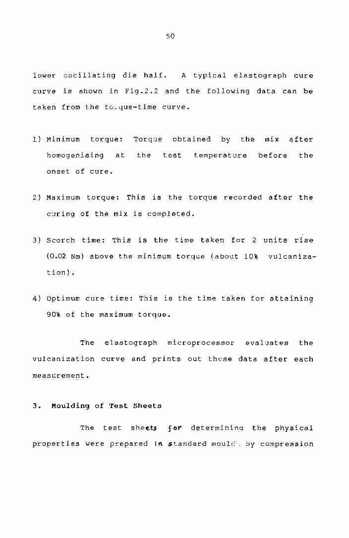
lower oscillating die half. A typical elastograph cure
curve is shown in Fig.2.2 and the following data can be
taken from the tOLyue-time curve.
1) Minimum torque: Torque obtained by the mix after
homogenising at the test temperature before the
onset of cure.
2) Maximum torque: This is the torque recorded after the
curing of the mix is completed.
3) Scorch time: This is the time taken for 2 units rise
(0.02 Nm) above the minimum torque (about 10% vulcaniza
t ion) •
4) optimum cure time: This is the time taken for attaining
90% of the maximum torque.
The elastograph microprocessor evaluates the
vulcanization curve and prints out these data after each
measurement.
3. Moulding of Test Sheets
The test sheets for determinina the physical
properties were prepared in. standard mould" by compression

l6
'.2
E
z 0.
8 ..
W
:J g o l-
0-4
A-
MA
XIM
UM
TO
RQ
UE
B-
MIN
IMU
M
TOR
QU
E
I i
' .
°l
36
48
24
GO
TIM
E (
MIN
)
Fig
.2.2
: A
ty
pic
al
Ela
sto
gra
ph
cu
re
cu
rve
V1 ~

52
moulding on a single day light electrically heated press
having 30x30 cm platens at a pressure of 120 kg/cm 2 on the
mould, upto the optimum cure time. Mouldings were cooled
quickly in water at the end of the curing cycle and stored
in a cold and dark place for 24 hours and were used for
subsequent physical tests. For compression moulding of
thermoplastics, specially designed moulds with provision
for cool ing under pressure were used. In the case of
thermoplastics, moulding
determined by trial
ASTM 0 3182 (1982).
and
4. Physical Test Methods
temperature and time were
error methods according to
At least five specimens per sample were tested
for each property as follows and mean values are reported.
a) Tensile stress--strain behaviour
Tensile properties of the elastomer blends were
determined according to ASTM 0 412 (1980) using dumbell
specimens on a zwick universal testing machine model 1445.
All the tests were carried out at 28 ± 2°C. Samples were
punched out from compression moulded sheets using a
dumbell die (C-type). The thickness of the narrow portion

53
was measured by a bench thickness gauge. The sample was
held tight by the two grips, the upper grip of which was
fixed. The rate of separation of the power actuated lower
grip was fixed at 500 mm/min. for elastomeric specimens.
The tensile properties of the thermoplastic blends were
determined according to ASTM D 638 on the Zwick universal
testing machine using a cross head sp~ed of 50 mm/min.
The tensile strength, elongation at break and modulus are
evaluated and printed out after each measurement by the
microprocessor.
b) Hardness measurements
The hardness (shore A) of the moulded samples
was tested using Zwick 3114 hardness tester in accordance
with ASTM D 2240 (1981). The tests were performed on
mechani call y uns t res sed sampl es of 300 mm diameter and
minimum 6 mm thickness. A load of 12.5 N was applied and
the readings were taken after 10 seconds of the indenta-
tion after firm contact had been established with
specimens.
5. Limiting Oxygen Index Measurement
The relative flammability of PVC blends was
measured by the limiting oxygen index method according to

54
ASTM D 2863-74. Limiting oxygen index is the minimum
concentration of oxygen expressed as volume per cent, in a
mixture of oxygen and nitrogen that will just support
combustion of a material initially at room temperature.
The test specimen of desired dimension is kept vertically
in the test column. The flow rates are set so that the
desired initial concentration of oxygen is flowing through
the col umn. The top of the specimen is then exposed to
the i g nit ion flame. The procedure is then repeated with
gradually increasing the oxygen flow rate so that the
specimen is well lighted at a particular concentration of
oxygen. The limiting oxygen index (LoT) is calculated
according to the equation,
LOI =
where O2 = volumetric flow of 3 oxygen mm /s at the
concentration when the specimen is ignited Md N2 = corres-
3 ponding volumetric flow of nitrogen mm Is.
6. Chemical/Swelling Resistance Determination
Chemical/swelling resistance of the samples was
determined according to ASTM D 471. Samples of desired
dimensions were punched out from the compression moulded

55
sheets, weighed and kept ln respective chemicals at
labora tory temperature for t he spec i f i ed per i od of time.
The samples were taken out, quickly dried with a filter
paper and weighed. The percentage change in weight was
calculated.
7. Rheological Evaluation using a Capillary Rheometer
Capillary rheometer is widely used for deter-
mining the rheological properties of polymer melts since
they cover a shear rate range of interest in practical
processing upto (10,000 S-l) with good reproducibility.
In this study, the rheological properties of polymers and
polymer blends were measured using a Goettfert viscotester
model 1500 as per ASTM 0 3835-79.
Apparent shear stress at the wall and shear rate
at the wall were calculated from Poiseuille law for
steady, fully developed capillary flow.
Apparent shear stress at the wall (LW app
Apparent shear rate at the wall(tw ) app
Apparent viscosity (~ )
56
where oAP is the pressure drop (N/m 2 )
Q is the volume flow rate (m 3 /S)
R is the capillary radius (m)
L is the capillary length (m)
A straight line relationship between 'till and app
'Y on a log-log plot indicates that the variables can wapp
be related by a power law equation 1'''''a K.r n where K ~pp - pp
is the consistency index and n the power law index. This
law IS often- referred to as the power law of Ostwald and
de 9-11 Waele. The power law index ( n ) indicates how
rapidly the viscosity varies with shear rate. For
pseudoplastic fluids the power law index ranges from
1 to o. When the power law index is unity, the fluid is
Newtonian and the consistency index becomes the Newtonian
viscosity. The powerlaw index indicates the degree of
non-Newtonian behaviour.
A series of corrections IS appropriate to derive
the true viscosity to account for factors such as,
1. Non-Newtonian behaviour of melts
correction)
(Rabinowitsch
2. Ends pressure drop (Bagley correction)
3. Reservoir and friction losses

57
4. Slip at the die wall
5. Influence of pressure on viscosity
6. Influence of pressure on volume
7. Influence of heat generation
8. Influence of decomposition on temperature
9. Modification of the material due to work in the die.
These corrections themselves are subject to many
errors and therefore should be used with caution.
Correct ions for the first two are generally recommended.
Because the polymer melts are in general non-
Newtonian it is necessary to correct the apparent shear
rate. Rabinowitsch 12 and Mooney13 derived the relation-
ship between true shear rate (Y ) and apparent shear rate w
(i' as, w
app
=
d In Y wapp
d In t can wapp
tw and t w
app app
i'w d In 'i"w app (3 + 4 d
a pp ) 1 n 1:
wapp
be taken as the slope
at various points.
of the curve (n) of
58
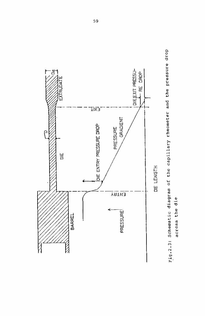
14 Bagley observed that a plot of pressure drop
vs die length to radius ratio at a fixed wall shear rate
gives a straight line with an intercept such that the
shear stress in capillary flow is more correctly
where P c
(Fig.2.3).
determined
is itself
= AP - Pc R
L )"2
is the pressure drop at the die entrance
The entrance pressure drop may be ideally
by using dies of several lengths.
The true viscosity may then be determined as,
The measurement of entrance pressure loss
a useful rheological parameter since P c
(p ) c
is
directly related to the elastic properties of the melt.
The most obvious elastic effect during capillary extrusion
is post-extrusion swelling.
a) Melt elasticity measurements
Polymers are partly viscous and partly elastic.
In the molten state, polymers are primarily viscous but
BA
RR
EL
PRE
55U
RJ
'\
<:: ~<"
«<<:
:<<<
'(<:
:<\:
<::[
<0,(
<<<<
<<"<
:'(~
~~~1
0:-~J
zl
Wj J I
DIE
EN
TRY
PR
ES
SU
RE
DR
OP
PR
ES
SU
RE
G
RA
DlE
NT
---~.-
DIE
LEN
GT
H
I d ~I I
De
..... >
> }
) )
) »
) )
J
XlT
PR
ES
SU
....
k l'
RE
DR
OP
Fig
.2.3
: S
ch
em
ati
c
dia
gra
m
of
the cap
illa
ry
rheo
mete
r an
d
the
pre
ssu
re
dro
p
acro
ss
the d
ie
Vl
\.D

60
will be elastic to some extent. This behaviour is
generally referred to as visco elastic behaviour. High
polymeric liquids show pronounced elastic properties
during flow. The normal stress built up in such materials
can exceed shear stresses by a larger aider of magnitude
and cause losses of pressure at the inlet and outlet of
the capillary, extrudate swell and in extreme cases other
undesirable flow phenomena.
The extrudate swell De
ratio, [) where De and Dare
the diameter of the extrudate and the die respectively is
a direct measure of the melt elasticity. Extrudate
swelling of two phase blends is composed of two parts
(i) matrix swell and (it) form recovery of dispersed drops.
Bogue and W hit el5 suggested the use of the parameter
recoverable shear strain 'fR for describing and distinguishing
the fluid elasticity of different viscoelastic fluids as a
function of shear stress. 'fR can be calculated from the
expression)
=
YR increases with increasing shear stress.

61
The measurement of extrudate swell ratio is
correlated with normal stress functions according to the
, . 16 Tanners equatlon.
2 T w [ 2 ( De /0) 6 app
In the present investigations the extrudate
emerging from the capillary was collected taking care to
avoid any deformation The diameter of the extrudate was
measured at various points and the extrudate swell ratio
was measured.
b) Observation of extrudate appearence
The extrudate from capillary rheometer may
provide useful visual evidence of non-laminar flow or
surface imperfect ions. The extrudate appearence may be
used to assess the quality of flow behaviour during
processing and also to obtain evidence of rupture
behaviour and the shear rate at which flow instabilities
commence.
c) Activation energy for viscous flow
The viscosity of a polymer decreases as the
temperature increases. Over a small region of temperature
62
variation, the temperature dependence of viscosity can be
represented by the equation,
"'\ app = A E/RT
.exp
where A IS a constant, E the activation energy, R the gas
constant and T the absolute temperature. A plot of
~ against liT gives an Arrhenius plot. lapp
d) Melt index measurements
The melt index tester is a simple capillary
rheometer. The piston IS driven down by placing a weight
on top of it.
The melt index is the number of grams of polymer
extruded in a time period of 10 minutes at a specified
temperature. The measurement procedure IS described In
ASTM D 1238. This index IS generally used for charact-
erization of polyolefines.
e) Mooney viscosity measurements
The Mooney viscosities of the raw rubbers were
measured on the Mooney viscometer which is designed for
measuring the shearing viscosity of rubber and rubber like

63
materials by a disc rotating (2 rev/min) in a cylindrical
cavity set at 100°C and filled with rubber under test.
In running a viscosity test the. sample was allowed to warm
up for one minute after the platens were closed and the
motor was then started. Reading after 4 minutes was
reported as the Mooney viscosity of rubber [ML(1+4) at
100°C 1. The procedure given ln ASTM D 1646 (1981) was
followed.
8. Infrared Spectroscopy
IR spectra given in this investigation were taken
in a Beckmann Infrared spectrophotometer. Different
functional groups and structural features ln the molecule
absorb electro-magnetic
frequenc:'es. Absorpcion
radiations
at 1700 cm- l
at characteristic
was made use of ln
this s t uay beca use it is a ppropr ia t e for carboxyl group
determination.
9. Radiation Studies
Test samples (2 ± 0.2 mm thick) were irradiated
with Gamma-rays from a source in a Gamma chamber.
The samples were irradiated for different radiation doses
64
at a dose rate of 0.157 Mrad/h in air at room temperature.
The mecha n i ca 1 pro pert i es we re measured be fore and after
irradiation.
la. Polymer to Metal Bond Strength Measurement
Adhesive strength of polymer samples with metals
was measured using a Zwick universal testing machine. The
meta 1 spec i mens were cl ea ned wi t h emery paper, and then
degreased. The adherends were obtained by hot pressing
the polymer sample, kept in between two meta 1 sheets at
pressure
3 minutes in a
of 120 kg/cm~.
laboratory hydraulic press at a
After removal of pressure and
cooling to room temperature, peel resistance of the joint
was determined. Peel strength was assessed from the
resistance to peeling of a 25 mm strip, the angle of
peeling being 180 0 at 50 mm/min test speed. The reported
values of peel force (N/mm) represent the mean from
measurements of 4 strips.
11. Morphology Studies
The morphology of polymer hlends was investigated
using an optical microscope (Versamet-2 Union 7596).

65
For optical microscopy a compression set test piece was
cut to a convenient size and mounted on a microscope
slide.
of 330.
Photographs were taken at magnification

66
REFERENCES
1. J.T.Lutt., Degradation and Stabilisation of PVC,
E • D • Owe n ( E d ), EIs e vie r, A p pI i e d S c i en c e Pub 1 ish e r s ,
p.253, (1984).
2. Tom Hawkins, J. Vinyl Tech. 4 116 (1982)
3. W.S.Penn, PVC Technology, Applied Science Publishers,
London, p.195 (1971).
4. D.J.Dunne, Plast. Rubb. Process. Appln. 3 (4) 337
(1983).
5. K.E.George, R.Joseph and D.J.Francis, Plast. Rubb.
Process· App1. 5 (2) 179 (1985).
6 • \-J • '/ • Tit:) W , PVC T e c h n 0 log y , El s e vie rAp p 1 i e d S c i en c e
Publishers, Chapter 6, p.324 (1984).
7. Z.Bartha, P.Erdos and J.Matis, Int. Polym. Sci.
Technol. 10 (6) T/50 (1983).
8 • L • L • B 1 y 1 era n d J. H • D a a ne, Po 1 yrn • En g • S c i. 7 1 78
(1967).

67
9. J.E.Goodrich and R.S.Porter Polym. Eng. Sci. 7 45
(1967).
10. W.Ostwald t Kol1oid-2 t 36 99 (1925).
11. A de Wae1et Oil and Colour Chem. Assoc. J. 6 33
(1923).
12. B.Rabinowitsch, Z. Phys. Chem. A145 1 (1929).
13. M.Mooney t J. Rheol·2 210 (1931).
14. E.B.Bagley, J. Appl. Phys. 28 624 (1957).
15. C.D.Han, Rheology In Polymer Processing, Academic
Press, New York, Chapter 5 (~976).
16. R.I.Tanner, J.Polym. Sci. A28 2067 (1970).

Chapter 3
STUDIES ON POLY(VINYL CHLORIDE)/ELASTOMER BLENDS

STUDIES ON POLY(VINYL CHLORIDE)/ELASTOMER BLENDS
Blends of several elastomers wi th pvC have been
developed to achieve a number of purposes. Modifying
polar and nonpolar elastomers with pvC is one of the
promising methods of improving the oil, petrol, ozone and
fire resistance of the vulcanizates based on them. l ,2 One
of the commercially important and miscible polymer blends
is that of NBR and PVC. The pr imary purpose of such
blends is to provide NBR having enhanced ozone resistance.
However, PVC also serves to reinforce the rubber.
Modulus, hardness and abrasion resistance increase with
increasing PVC 3,4
content. Tensile strength also
frequently increases with PVC content while elongation
decreases. When PVC 1S modified with NBR, it serves as a
polymeric
Pvc. 5 - 8 plasticizer
PVC/CR BLENDS
Polychloroprene
and improves the toughness of
rubber (eR) and poly(vinyl
chloride) (PVC) both possess excellent oil resistance,
chemical resistance, weather resistance and non-
flammability. Hence modi fying CR wi th PVC would be an
68
69
excellent way of improving its mechanical strength without
losing any of the useful properties of CR. pvc is
generally used as a cheap plastic material whereas CR is
used as a comparatively high priced special rubber. Hence
blends of CR and pvc can be advantageously used to replace
o 10 0 9,10 CR 1n many app lcat10ns.
However, it has not been possible to achieve a
marked improvement in the physico-mechanical proper~ies of
the vUlcanizates based on CR when modified with PVC.
Blends 0 f such immisc i bl e po 1 ymer s have complex property
relationships that are rarely additive. The poor
mechanical behaviour of the phase separated blends is
usually the consequence of inadequate adhesicn between the
phases that does not allow efficient transfer of stress
o 11-13 across the 1nterface. Mechanical proper::es wculd be
n ear 1 y a a d i t i '1 e i f the i n t e r f a cia 1 Z 0 n e 1 s s t re n g : hen ea.
Suitably chosen additives are used to reduce the inter-
facial tension and 1n this way the blend can be brought
into more wider applications. Block and graft copolymers
have been founa to be the most useful In modifying the
interface or to act as compatibi1ising 14-17 agents.
Statistical copolymers have also been found to be useful
to a 1 imi ted extent as in t he case 0 f et hy lene-propy 1 ene
rubber
density
70
(EPR) compatibilizing polypropylene
18-21 polyethylene. In the present
and high
studYI an
attempt is made to modify PVC/CR blends so as to improve
their mechanical behaviour. The main thrust of the work
is the use of selected compatibilisers in blends of PVC
and CR. The materials tried as compatibilisers are block
and random copolymers of the following types:
Hytrel - A polyether-ester block copolymer
NBR Acrylonitrile-butadiene rubber
EVA Ethylene-vinyl acetate copolymer
SIS Styrene-isoprene-styrene block copolymer
SBS Styrene-butadiene-styrene block copolymer
SEBS Styrene-ethylene-butylene-styrene block
copolymer.
FUSION STUDIES
Since the fusion state of PVC is a critical
factor in determining the mechanical strength of PVC
blends l the efficiency of the various compatibilisers was
first compared based on their ability to modify the fusion
behaviour of PVC/CR blends. The addition of a true
compatibiliser decreases the fusion time and thereby

71
improves the processability. A common method of investi-
gating the fusion process is to subject the material to an
appropriate shear and temperature in a Brabender mixer and
h . h f' f' 6,22 t en to monItor t e torque as a unctIon 0 tlme. By
this mechanical and thermal treatment all primary
particles of PVC are destroyed ~esulting in an apparently
homogentous state which can be observed from the torque-
time curve.
Experimental
Fusion characteristics of a SO/50 PVC/CR blend
with and without various polymeric modifiers were studied
at two temperatures 150°C and 170°C ln a Brabender
plasticorder uSIng roller mIxers at 30 rpm soeed. The
fusion time of each blend is given In Table 3.1.
Results and Discussion
It can be observed that the time required to fuse
the PVC compound (fusion time) is significantly reduced by
EVA, Hytrel and NBR which are common plasticizers of PVC.
The other additives give only little or no reduction in
the fusion time. Hence these three additives EVA, Hytrel
and NBR were selected as modifiers / compatibilisers for
further studies.

72
Table 3.1: Fusion time of 50/50 PVC/CR in the presence of
various modifiers
PVC/CR blend rpm Temperature Fusion time ( °C) (minutes)
Unmodified 30 150 12..0
EVA modified 30 150 7.0
Hytrel modified 30 150 7.5
NBR modified 30 150 7.0
SIS modified 30 150 10.5
SBS modified 30 150 10.0
SEBS modified 30 150 :) r ~ • ::J
Unmodified 30 170 3.0
EVA modified 30 170 5 . 5
Hytrel modified 30 170 0.0
NBR modified 30 170 ,_ r
c.:)
SIS modified 30 170 -:'.0
SBS modified 30 170 i • J
SEBS modified 30 170 8.0

73
A faster fusion also lowers the demands on the
PVC stabiliser and results in more stable PVC compounds.
It is confirmed by static and dynamic thermal stability
tests.
THERMAL STABILITY OF PVC IN PRESENCE OF MODIFIERS
The maln outward manifestations of thermal
degradation of PVC are the evolution of hydrogen chloride
and the development of colour. It is widely accepted that
the cleavage of HCl is accompanied by polyene sequence
f " d 1" k" 23,24 ormatlon an cross ln lng. As a result the polymer
discolours from light yellow to dark brown and almost
black in severe case. In this study the thermal stability
of PVC in presence of the modifiers is invesLigated.
Experimental
25-27 In the dynamic thermal stability tests 40 gm
of 50/50 PVC/modifier blends without any stabiliser for
PVC were worked at 170°C and 30 rpm in the Brabender
plasticorder mixer for 20 minutes and the torque-time
curves were taken. Also, the sequence of colour develop-
ment for each of the above compounds during the test run
was visually observed at every 3 minutes.

74
In the static thermal stability test 25 - 27 the
PVC/modifier blends were made into sheets of standard size
and kept in an air oven at 180°C for a period of 100
minutes. The colour change was noted at every 10 minutes.
Results and Discussion
Fig.3.l shows the Brabender torque-time curves of
the 50/50 PVC/modi f ier blends. The in i t ia 1 unsta ble part
may be the period of homogenisation. The period over
which the constant torque level continues (sLability time)
may be taken as a measure of the efficiency of the
stabilising system. It is found that. these modifiers
improve the stability time and reduce the degradation
tendency of ?VC considerably. The stability time is found
to be least when NBR is used as the modifier, maximum 1n
the case of EVA and that for Hytrel being in between those
of NBR and E',' A.
Table 3.2 shows the colour development in the
PVC/modifier blends during the dynamic thermal stability
test and Table 3.3 during the static thermal stability test.
An examination of the colour changes occuring during the
dynamic test run shows that the maximum colour development

800
60
0f-
40
0
01
L ~
w
;::J
0 a:
0 ~
20
0 o
\ \ \
\ \
",,-\
\.
"-\"
'----
".. ",
------
-"-
'.....
.....
--..
A.
PV
C/E
VA
( 5
0/5
0 )
B
PV
C/H
YT
RE
L (
50
/50
)
C
PV C
iNB
R (
50
/50
)
- - -..--
---
---/"
.......
/"
/"
....... c
.......
B
_/' --
... ---A
--'-.
...
---~
----
---
---------
------
----
----
--------
.1
i i
4 8
12
16
20
TIM
E (
MIN
)
Fig
.3.1
: B
rab
en
der
torq
ue-t
ime
cu
rves
of
50
/50
P
VC
/mo
dif
ier
ble
nd
s
--J
V1

76
Table 3.2: Sequence of colour change during dynamic
thermal stability tests-50/50 PVC/modifier blends
Time in 0 minutes 6 9 12 15
PVC/EVA 0 0 1 1 3 4
PVC/Hytrel 0 1 3 5 6 8
PVC/NBR 0 1 4 5 7 9
Degree of colour development over the scale 0-10
o - colourless ; 10 - black
18 21
6 6
9 10
10 10
Table 3.3: Sequence of colour change during static ~hermal
stability tesr.-50/S0 PVC/modifier blends.
Time ::..n 10 20 30 ~o 50 60 70 80 90 100 minutes
PVC/E\'A 1 2 3 :) 6 6 6 7 8 8
PVC/Hytrel 4 5 5 6 , 8 8 9 10 10
PVC/NBR 3 4 5 7 8 8 9 10 10 10
Degree of colour development over the scale 0-10
o - colourless ; 10 - black

77
occurs when NBR is used. In the case of EVA modified
blend the discolouration occurs very slowly. The results
of the static thermal stability tests confirm the results
obtained from the dynamic thermal tests.
HYTREL, EVA AND NBR AS MODIFIERS FOR PVC/ELASTOMER BLENDS
Te~nary blends are gaining an important share in
the :ield of property diversification of polymer blends.
These systems
of miscible
offer the possibility of extending the lis~
or mechanically compatible blends.
Theoreticallv their study offers the possibility to
explore the important principles gO"Jerning the compati
bilization of immiscible or nearly miscible blends.
In this study, Hytrel, EVA and
modifiers for different PVC/Elastomer
NBR are tried as
blends. The
chemical structure of the modifiers are shown in Fig.3.2.
Experimental
blends were prepared 1n the Brabender The
plasticorder. The formulations employed with each polymer
are shown in Table 3.4.

78
ICH-CH-CH-CH l L222
1Tn
C-OCH3 11 o
EVA
rCH-CH=CH-CH-CH-CHl L 2 2 2 \ In CN
NBR
fI I1 tI IJ to 0 tt-0 0 . t
C-@-C-O-(CH2tO n C~Cf°--(CH2)~O m
Hytrel
Fig.3.2: Structure of EVA, NBR and Hytrel
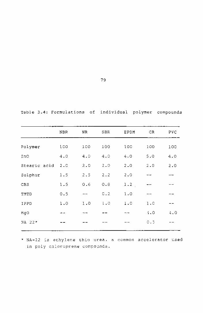
79
Table 3.4: Formulations of individual polymer compounds
NBR NR SBR EPDM CR PVC
Polymer 100 100 100 100 100 100
ZnO 4.0 4.0 4.0 4.0 5.0 4.0
Stearic acid 2.0 2.0 2.0 2.0 2.0 2.0
Sulphur 1.5 2.5 2.2 2.0
CBS 1.5 0.6 0.8 1.2
TMTD 0.5 0.2 1.0
IPPD 1.0 1.0 1.0 1.0 1.0
MgO 4.0 4.0
NA 22* O.S
* NA-22 1S ethylene thio urea, a common accelerator used
in poly chloroprene compounds.

80
The PVC content of the blends was varied from
0-50% of the total polymer, since beyond this level it is
difficult to process the blend under the test conditions.
The elastomer was added first, then the compatibiliser and
finally PVC. This sequence permitted the use of low
tempera t ures of blend i ng and hence polymer degrada t ions
were kept to minimum. PVC stabilisers were added along
with PVC but the additives for the elastomers were added
after the preparation of the base polymer blend.
MgO/ZnO/stearic acid system was used as the heat
stabiliser for PVC, since it does not affect the elastomer
adversely. 28,29
Sulphur curing was employed for SBR, EPDM
and NR while MgO/znO curing was employed for CR. The
compatibiliser concentration was kept at 10% of the total
polymer in every case since this level was found to be a
good compromise.
any additives.
The compa t i bi 1 i sers were added w i thou t
The CUre curves of the blends were taken at 170°C
on a Goettfert elastograph. The compounds were vulcanized
upto their optimum cure times in a laboratory hydraulic
press, at the same temperature. The mechanical properties
of the vulcanizates were determined on a Zwick universal
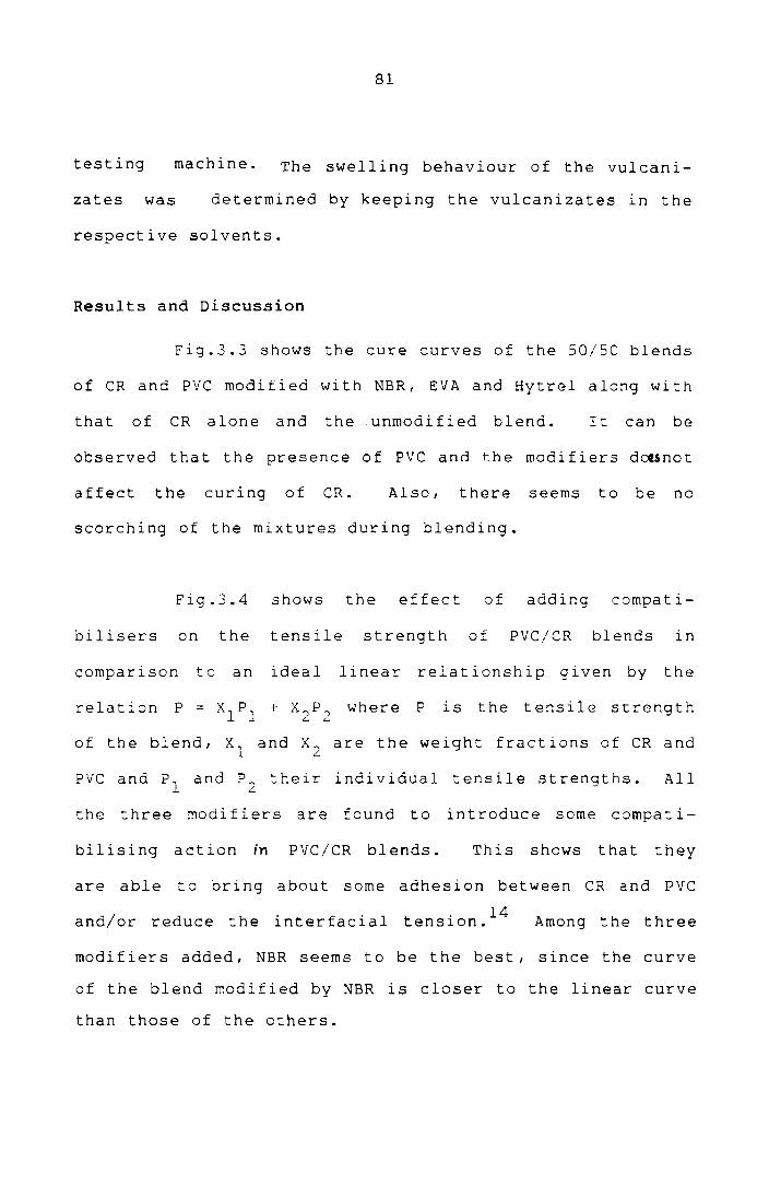
81
testing machine. The swelling behaviour of the vulcani-
zates was determined by keeping the vulcanizates in the
respective solvents.
Results and Discussion
Fig.3.3 shows the cure curves of the 50/50 blends
of CR and PVC modified with NBR, EVA and Hytrel along with
that of CR alone and the unmodified blend. I t can be
observed that the presence of PVC and the modifiers d~5not
affect the curing of CR. Also I there seems to be no
scorching of the mixtures during blending.
Fig.3.4 shows the effect of adding compati-
bilisers on the tensile strength of PVC/CR blends in
comparison to an ideal linear relationship given by the
relation P == XlP1
+ X2
P2
where P 1S the tensile strength
of the blend, Xl and X2
are the weight fractions of CR and
PVC and Pl
and P2
their individual tensile strengths. All
the three modifiers are found to introduce some compati-
bilising action in PVC/CR blends. This shows that they
are able to bring about some adhesion between CR and PVC
and/or reduce the interfacial . 14 tens1on. Among the three
modifiers added, NBR seems to be the best, since the curve
of the blend modified by NBR is closer to the linear curve
than those of the others.

E
z "' w
::
J 0 Ir
0 ~
0.6
0.4
eR
AL
ON
E
2 N
BR
M
OD
I FIE
D
3 H
YTR
E L
M
OD
IFIE
D
4 E
VA
M
OD
IFIE
D
5 U
NM
OD
IFIE
D
~.
O.
I I
o 3
6 9
TIM
E(M
N)
Fig
.3.3
: C
ure
cu
rves
of
50
/50
P
VC
/CR
b
len
ds
2
.-:~:
00
N
5
12

... ::I: Ie) Z W Cl: IIJ)
W .....J lJ) Z W f- 4
o o
83
'V LINEAR
A N BR MODIFIED
6. EVA MODIFIED
10 20 PVC 30 CONTENT( °/. )
F' 19.3.4.· V ariat' Ion of tensile
blends·with PVC content
40
strength of PVC/CR
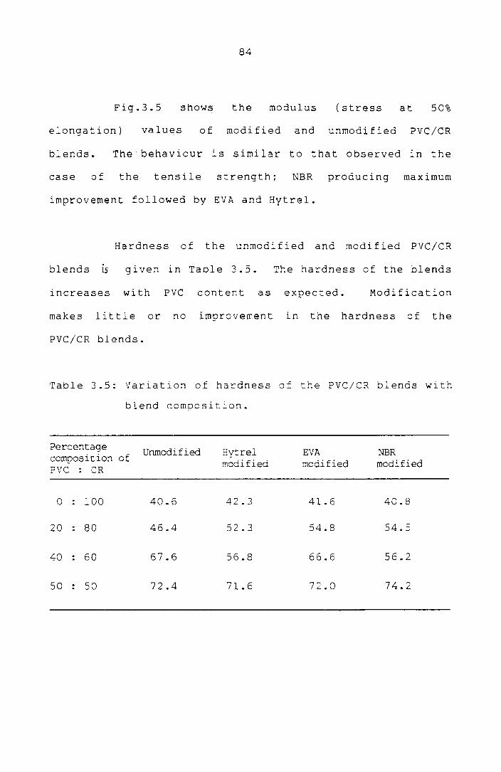
84
Fig.3.5 shows the modulus (stress at 50%
elongation) values of modified and unmodified PVC/CR
blends. The behaviour is similar to that observed in the
case of the tensile strength; NBR producing maximum
improvement followed by EVA and Hytrel.
Hardness of the unmodified and modified PVC/CR
b 1 end s 15 g i v e n i n Tab 1 e 3. 5 . The hardness of the blends
increases with PVC content as expected. Modification
makes 1 it tl e or no improvemen tin the hardnes s 0 f the
PVC/CR blends.
Table 3.5: Variation of hardness of the PVC/CR blends with
blend composit~on.
Percentage Unmodified Hytrel EVA NBR composition of modified modified modified PVC : eR
0 100 40.6 42.3 41.6 40.8
20 80 46.4 52.3 54.8 54.5
40 60 67.6 56.8 66.6 56.2
50 50 72.4 71.6 72.0 74.2

lfl' 8 :::J ..J :::J o o 2:
.. N BR MODIFIED
• EVA MODIFIED
6. HYJREL MODIFIED
o UNMODIFIED
85
o~_~ o 1100----~~----~ 20 30 PVC CQNTENT(°f.)
F' on of 19.3.5: V ariati pvc cont . ent
modulus of
40 50
pvc/eR blends with

86
As possible applications for the PVC/CR blendsJ
their swelling behaviour in some common solvents and their
flammability characteristics as indicated by limiting
oxygen index values are compared in Table 3.6. It can be
observed that PVC/CR bl ends 0 f fer si gni f i can t advan tage
over the commercially available PVC/NBR blends in the
areas of swelling r-esistance and r-esistance to
flammability.
Mechanism of Modification
In the case of NBR, the polar acrylonitrile and
the nonpolar- butadiene may be compatibilising the domains
at the inter-face giving good mechanical compatibility.
The polarity of ?inyl acetate and the nonpolarity of
ethylene may be contributing to the compatibilising action of
EVA. In the case of Hytrel, the interaction beLween the
carbonyl group of the Hytrel and the ~-hydrogen of the PVC
and CR are also likely to contribute to compatibility In
addition to the similar solubility par-ameter-s. 12
Another r-eason for the compatibilising action in
the case of PVC blends may be the modification of the
fusion behaviour of PVC. Fig.3.6 shows the fusion
behaviour of 50/50 blends of PVC/NBR, PVC/EVA and

87
Table 3.6: Comparison of properties of PVC/CR and PVC/NBR
blends
percent- PVC/CR BLEND age
Unmodi- Hytre1 PVC/NBR Property compo- EVA NBR sition fied mofi- modi- modi- blend of PVC fied fied fied
x 0 34.0 33.0 33.0 33.S 19.0 Cl> '0 c: 20 36.5 35.0 33.5 33.0 20.8 .,-i
c: 40 43.0 38.5 38.0 39.0 25.0 Cl> 0'1 >< 50 44.0 40.0 41.0 39.5 28.5 x 0
M . 0 2.7 2.7 2.7 2.5 1.2 0 [f) z >< 20 2.2 2.6 2.3 2.2 1.2 ro ....., '0
-,-i
0 40 1.8 2.2 2.1 2.0 1.7 r-- ~ 50 1.8 2.2 1.9 1.8 1.8 c: Cl)
-.-i .:(
.w .c 0 240.0 242.0 241.0 239.8 249.0 0'1 Cl> -.-i c:
Cl> Cl> 20 206.1 212.1 202.3 182.6 226.1 ~ :l .....,
40 148.2 181.3 178.4 140.9 189.0 c: 0 -.-i ~
Cl> 50 142.1 168.2 137.6 139.0 lE4.1
[f)
ro Cl> ... 0 46.1 45.9 46.8 44.0 49.0 u '0 c: -,-i
-,-i u 20 32.9 40.0 38.2 32.3 45.6 ro c!P u 40 25.3 27 .6 29.6 18.1 32.8 -.-i
.w >< Cl> 50 24.8 19.2 20.1 15.0 23.1 u Cl> .::c '0 c:
-.-i ....., 0 61.2 62.6 61.6 61.2 197.2 0'1 :>. c: .c
86.4 .w 20 98.6 64.0 92.3 184.8 -.-i Cl> .-t ....., ....., Cl> 40 100.0 110.2 97.8 112.3 144.8
Cl> ><c: ~ .c 0
.w.w 50 104.1 111.6 117.7 113.4 116.6 Cl) Cl> Cl> ::E:~

E
z "
w ~
o er:
o t-
40
30
20
OiA
o
2
C
C
4
o 1
PV
C /
NS
R
BL
EN
D
2 P
VC
IH
YT
RE
L
SL
EN
D
D
_ 0
_ 3
PV
C/
EV
A B
LE
ND
A
AD
DIT
ION
OF
NB
R,H
YT
RE
L &
EV
A
B
AD
DIT
ION
OF
PV
C
C. F
US
ION
F
DIN
T
o E
OU
ILlB
RIU
M
PO
INT
6 8
TIM
E(
MIN
)
10
Fig
.3.6
: F
usio
n
beh
av
iou
r o
f 5
0/5
0
ble
nd
s
of
PV
C/N
BR
, P
VC
/EV
A
an
d
PV
C/H
yll
:el
ule
nd
s
CD
CD

89
PVC/Hytrel. At the maximum torque (fusion point) most of
the primary particles are likely to be fused together, but
are still distinguishable. After the fusion point the
melt temperature increases significantly causing a
reduction in the melt viscosity and torque. At this point
the particulate structure starts to disappear. The
temperature continues to rise and the viscosity decreases
until they level out to relatively constant value. At
this equilibrium point all primary particles may have
disappeared and a continuous melt ~s formed. It can be
observed from the figure that the fusion behaviour of PVC
is more uniform and rapid in presence of EVA, followed by
Hyt re 1 and NBR. In the case of PVC/NBR blend, a larger
lncrease in torque is observed (9-C) when PVC 1 S added.
This ~ay be taken as an evidence for a strong interaction
6 between the polymers. Fig.3.; shows the fusion behaviour
of SO/SOPVC/CR blends modified with NBR, EVA and Hytrel.
It can be observed that almost the same trend as in
Fig.3.6 is followed ~n this case also even at this low
concentrations of EVA, Hytrel and NBR. From the foregoing
it may be reasoned that the modifying action of NBR,
Hyt~el and EVA on PVC/CR blends ~tems from two factors:
(1) reduction in the interfacial tension between CR and
PVC (2) improvement in the fusion behaviour of PVC.

40
30
A. ADDITI~
OF
CR
B.
AD
DIT
ION
OF
NB
R/ E
VA
j H
YT
RE
L
c. A
DD
ITIO
N O
F
PV
C
D. F
US
ION
' P
OIN
T
E
EQ
UIL
IBR
IUM
P
OIN
T
0 _
_
E
20
1-
D
IJL
E
2
z ~
w
:J
a er
0 ~
f tl
-3
E
Jj
1 N
BR
M
OD
IFIE
D
2 H
YT
RE
L
MO
DIF
IED
101
If'-..
....,
----3
EV
A
MO
DIF
IED
0
C
C
A
o 2
4 6
8 10
T
IME
(M
IN)
Fig
.3.7
: F
usio
n
beh
av
iou
r o
f 5
0/5
0
PV
C/C
R
ble
nd
s
mo
dif
ied
w
ith
N
BR
,
Hy
trel
an
d
EVA
\.0
0

91
To verify the effect of the fusion behaviour of
PVC, Hytrel and EVA were tried as modifiers in PVC/NBR
blends. Fig.J.B shows the tensile strength of unmodified
and modified PVC/NBR blends. It is observed tha t Hyt reI
and EVA are able to bring about some improvement in the
strength of PVC/NBR blends. This may be solely due to the
modification of the fusion characteristics of PVC by them
since NBR was found to have stronger interactions w\th PVC
than Hytrel or EVA.
Thermoplastic Elastomers from CR and PVC
Blends of comparable amounts of elast:omers and
pvc can be used as thermoolastic elastomers or vulcanised
30 to form thermoset elastomers. The ~ensile prope~ties of
the 50/50 PVC/CR blend and modified blends are given
without vulcanising the rubber phase in Table J. -:. The
blend was a Iso reprocessed in the Brabender plas'Cicorder
and found to have comparable tensile properties after
reprocessing.
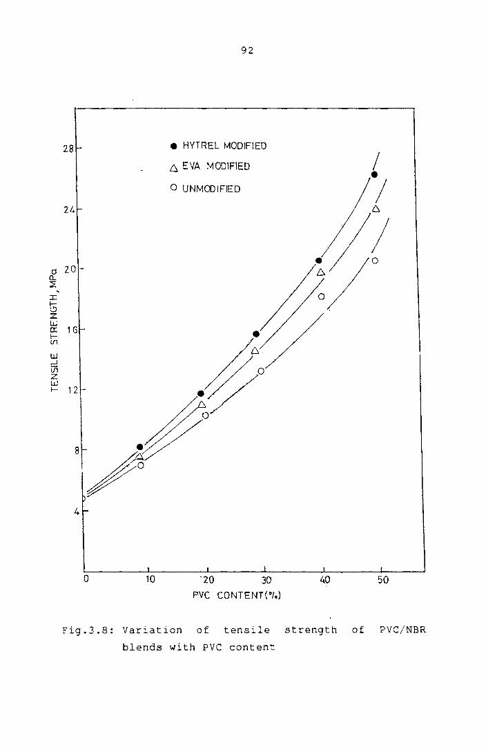
28
24
Cl zon. ~
" :r: G z W 0:: 1 G f--(/)
W ..J Vi Z W f-- 12
4
o 10
92
• HYTREL MODIFIEO
6, EYA MODIFIED
o UNMODIFIED
30
PVC CONTENT(°fo)
40 50
Fig.3.8: Variation of tensile strength of PVC/NBR
blends with PVC content

93
Table 3.7: Tensile properties of 50/50 PVC/CR blends
(Rubber phase unvulcanised).
Tensile Strength Elongation in(MPa) at break (%)
Unmodified 5.2 78.0
EVA modified 8.9 91.4
Hytrel modified 8.2 96.1
NBR modified 9.6 129.6
THE EFFECT OF MODIFIERS ON THE MECHANICAL PROPERTIES OF
PVC WITH OTHER ELASTOMERS
Since EVA, Hytrel and NBR were found to be
effective modifiers in PVC/CR blends, they were also tried
as modifiers in blends of PVC wl~h other elastomers.
PVC/SBR Blends
Fig.3.9 shows the var:ar.ion of tensile strength
of PVC/SBR blends with and without modifiers. Though the
modifiers reduce the fusion time, they are able to make
only marginal improvements ln the tensile properties.
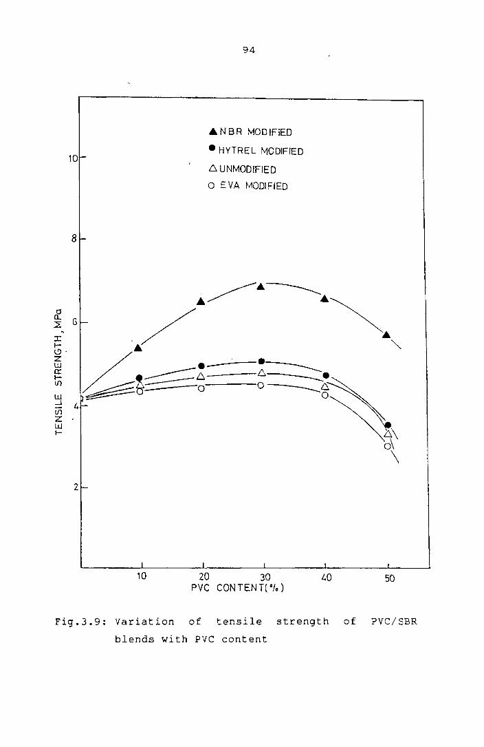
10
8
2
10
94
.6.NBR MODIFIED
• HYTREL MODIFIED
~ UNMODIFIED
o EVA MODIFIED
L.O
of tensile Variation Fig.3.9: PVC content
blends with
strength
50
of PVC/SBR

95
PVC/EPDM Blends
The effect of modifiers on the mechanical
properties in this case is also similar to that on PVC/SBR
blends (Fig.3.l0).
modification.
PVC/NR Blends
Only marginal improvements occur by
Fig.3.ll shows the variation of tensile strength
of PVC/NR blends with PVC content. Modification by EVA,
Hytrel and NBR makes no improvement in the case of PVC/NR
blends. This shows that there lS little interfacial
modification in this case. Further, the state of fusion
of PVC particles also may not have improved in this case.
In the case of NR, the high strength resul ts from the
ability of the elastomer to crystallize under high
strains. The addi t i on of PVC br i ngs down the st ra i ns,
evidently limiting the strength to a lower value.
RHEOLOGICAL EVALUATION OF THE PVC BLENDS
Since improvement ln the fusion state of PVC is
considered as one of the mechanisms by which EVA, Hytrel
and NBR work, it will be worthwhile to examine the
rheological behaviour of the blends of modifiers with PVC,

o o
Fig.3.l0:
10
96
• HYTREL MODIFIED
• EVA MODIFIED
6. UNMODIF lE 0
o NbR . D MODIFIED
20 PVC 30 CONTENT( 0/0 )
40 50
Variat" J.on of bl tensile ends with strength PVC content of PVC/EPDM
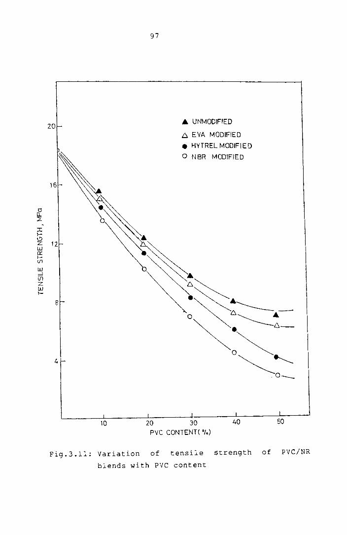
0 0.... 2-
~
I I-I..') z w 0:: I-V1
W .....J if) Z w I-
97
20 ... UNMODIFIED
D. EYA MODIFIED
• HYTREL MODIFIED
, o NSR MODIFltD
16
~ 12
~ :~.~-8
o ~"------A.
~. 6_
4 o~~ .0 __
10 20 30 40 50 PVC CONTENT( "10)
Fig.3.l1: Variation of tensile strength of PVC/NR
blends with PVC content

98
since it provides a means of gaining insight into the
structure of the polymer 31 melt. It is well known that
physical properties of polymer products are not only
dependant on the properties of the raw materials but also
on the processing condi tions. In the course of var ious
processing techniques, polymer melts will be subjected to
vary i ng shea rand elonga t i ona 1 de forma t ions. Determina-
tion of rheological func~ions at comparable shear and
temperatures used in actual processing will throw light on
h - b h - 32,33 t e processlng e aVlour.
Experimental
Polymer blends were prepared on the Brabender
plasticorder. Mixing conditions were 30 rpm and 170°C.
Initially, Hytrel, EVA or NBR was charged into the mixer
and then PVC along with its heat stabiliser (4 phr TBLS)
was added. A mixing time of 7 minutes was provided during
which the torque stabilised to a constant value in all
cases. The amount of PVC in t he blends was va r i ed from
o to 50% by weight of the polymers. After mixing, the
blends were sheeted out by passing on a laboratory mixing
mill and then granulated on a laboratory extruder attached
to the Brabender plasticorder. Melt rheological
properties were measured on a capillary rheometer

99 -G 5130 ~
(Goettfert viscotester 1500) using a capillary die of
circular cross section (length 30 mm and diameter 1 mm)
and also on the Brabender plasticorder at different shear
From volumetric flow rates at various applied
pressures, values of apparent shear stress at wall (Lw app
apparent shear rate(~wapp)' and apparent viscosity (~app)
were calculated using the following expressions,
, Ap R -- ,< ,',
1. <, ~. ~ ~ , = L 2" W ... '. . i app
~ = 4Q wapp it R3
l'
", a pp = wapp
'Iwapp
where Ap is the pressure difference between entrance and
exit regions of the capillary die, Q the volumetric flow
rate, and Land R the length and radius of the die
respectively.
From the log
power law exponent n
tw app
vs log 'fw plots, 'app
values of
were cal cula ted in accordence with
the following power law,
t w = app
where K lS a constant.
,.~. f .. .' .

100
Rabinowi tsch correct i on was appl i ed us i ng val ues
of n to obtain true shear rate ?w according to the
following expression. 34
[(3n+l)/4n]YuJ "app
Similarly the true shearstressat wall ~ was calculated by w
applying Bagley correction according to the following
. 35 expreSSlon.
Ap - p T = (_ c) R
w L 2"
where the entrance pressure loss (p) was evaluated from c
the flow data recorded with 3 different dies of L/R values
20, 40 and 60. The true ~iscosity was calculated as,
- /~ Lw' 'w
The rheological characterisation of the blends
d · b d 1 . d 36 was also one uSlng the Bra en er p astlcor er. The
torque was considered proportional to shear stress, speed
of rotation of the rotors to shear rate, and torque/rpm to
viscosity. The activation energy was measured by plotting
log (torque/rpm) against liT.

101
Results and Discussion
Fig.3.12 shows the flow curves of the PVC/EVA
blend. The slope of the curve (n) was calculated at
different points on the curve. Bagley plots ofAP as a
function of L/R for PVC/EVA blends at various shear rates
are shown in Fig.3.13. Then the true shear rate 'Y' and w
true shear stress 1 were calculated by applying the w
appropriate corrections. The influence of Rabinowitsch/
Bag 1 ey correct i on on the v iscos i t Y curve is demonst ra tea
in Fig. 3.14, where apparent viscosi ty and corrected or
true viscosity are plotted against shear rate. As can be
seen from the figure, the true viscosity curve is slightly
displaced from the apparent viscosity curve. However, the
nature of the curves remains more or less the same in both
cases. Since all the experiments in the presenc study
were done using a capillary die of fairly high L,R ratio
(60), end effects may be negligibly small and hence t mav wOofP -
be close to the true shear stress at the wall.37/~8 Also
since the present evaluations are of a comparative nature
the apparent
studies.
valuesof,( and w Y are reported for further
w
Fig.3.l5 shows the variation of viscosity with
shear rate of Hytrel and PVC/Hytrel blends, measured by
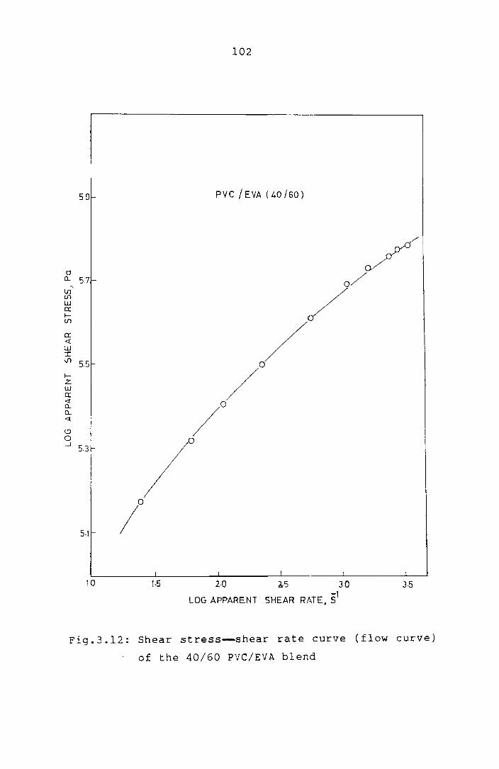
591-
o 0... 5.7-
"' V1 tfl W 0: lV)
0: <l: w :r: (f) 551-
I-Z W er: ~ 0... 0... <l:
<.9 o ....J 5.3-
5·11-
10
102
PVC/EVA(40J60)
f I I
'-5 2·0 a,5 30 3·5
LOG APPARENT SHEAR RATE, 51
Fig.3.12: Shear stress--shear rate curve (flow curve)
of the 40/60 PVC/EVA blend

60
50
o a.. ::E 40
., a.. <l a.. o a:: o
0
Fig.3.13: Bagley
various
103
20
L/R
plot of 40/60
shear rates
.1 40
2880.05'
/ 0/ ° / o
17280Y
° 115205'
60
PVC/EVA blend at

104
3.sr----------------------------.
3.0
1.1)
J: 26 .,
>-1-Cf)
o u Cf)
> ~ o --.J 2·2 r-
I j
1·5 2·0
TRUE VISCOSITY
APPARENT VISCOSITY
EVA
o PVC I EVA (40/60)
I
2·5 3-0 3·5
LOG SHEAR RATE~"$
Fig.3.14: Comparison of apparent and true viscosity
with shear rate for PVC/EVA blend

105
o HYTREL
6 PVC / HYTREL(20/aO)
GOD • PVC I HYTREl(L,O/60)
A PVC /HYTREl (50/50)
500
400
\f1
cl: >-~ 300-l-V)
8 V1 >
200
100
l-_____ -L-______ L-___ -'I_. _____ -'-
100) 2000 3CXX) 4000
SHEAR RATE ,$1
Fig.3.15: variation of viscosity with shear rate of
PVC/Hytrel blends at 170°C

106
the capillary rheometer (only the higher shear region is
shown since the linear axis cannot accommodate the
complete range). It can be observed that with increase in
Hytrel content the viscosity of the blend decreases which
means that Hytrel acts as a lubricant or plasticizer for
PVC. This behaviour has been observed for other polymeric
modifiers for pvc. 38 ,39 PVC particles fuse together
faster in presence of plasticizers and hence this may be
one of the ways in which Hytrel improves the mechanical
properties of the PVC blends since an improvement in the
fusion state leads to increased strength. Figs.3.16 and
3.17 show the viscosity-shear rate plots of PVC/EVA and
PVC/NBR blends. These blends also exhibit almost the same
behaviour as those of PVC/Hytrel blends showing an
effective decrease in overall viscosi:y wi:.h increase in
the concentrations of EVA or NBR. Another notable
observation from Figs.3.15 to 3.17 is that these three
modifiers make the behaviour of PVC less non-Newtonian.
This 1S expected since rigid PVC mel:s are characterised
by high viscosity and high pseudo plasticity.40 The melt
behaviour of the blends becomes more and more pseudo-
plastic with increase in PVC content. But with the
progressive addition of the modifiers a Newtonian
behaviour seems to develop at least in the low shear rate

V)
d Q
, >-l-
V)
0 u In >
107
500
0 EVA
6. PVC/'EVA( 20/80)
400 - PVC/ EVA (40/60)
A PVC/EVA (50/50)
300
~~~4~ ---~O ~.~ ~ 6 A 200 ~ .\, '\\
o,~ '- ~\ 6 " \. ~ \ ,
~ ~\~ 10 O~~ o~
~
<--_____ -,,--'-_____ -.J ___ , ___ ,~
1000 200J 3000 4000 SHEAR RATE) S1
Fig.3.16: variation of viscosity with shear rate of
PVC/EVA blends at 170°C

If)
Cl Q
~
900
800
7
600
> 500 I-
lfl o U lfl :;
400
300
~~
~. ~o ~
108
\
0 PVC IN BR (20/80)
• PVC/N BR (40/60)
6- PVC / NBR (SO/SOl.
\\ 0\ \\ \ 6,
\ \' \,
1000 20c0
SHEAR RATE, 51
\ ", \ o \ " \ \ \ , \ \
, \ 6 " \ \
~ 3000 4000
Fig.3.l7: variation of viscosity with shear rate of
PVC/NBR blends

109
region. Since rigid PVC melts, are characterised by high
viscosity and high pseudoplasticity, it follows that these
polyblends can be processed at lower temperatures and
d 1 38,40,41
shear rates as compare to PVC a one.
Fig.3.18 shows plots of log (shear stress) vs
log (shear rate) for Hytrel and for PVC!Hytrel blends at
The curve for Hytrel could not be approximated by
a single straight line which makes approximation to a
single power law relationship difficult. However, the
curve could be approximated as two straight lines with
different slopes and these two straight lines may be
associated with two flow mechanisms. Blends of Hytrel
with PVC also exhibit a similar behaviour. But in this
case the flow mechanisms indicated by the two straight
lines may have direct relation to the fusion of PVC
particles. In the region of low shear rates the straight
lines are fairly parallel to the initial straight line
shown by Hytrel. This may imply that at low shear rates,
capillary flow can occur without the individual particles
of PVC being 40
destroyed. For a given composition of
PVC!Hytrel blend and at a particular temperature there
seems to be a part i cular shea r rate above wh i ch doma in
interfaces are obliterated and conventional intermolecular

d Q. , tJ)
lf1 W a: ftJ)
a: <l W I tJ)
(9 o -.J
15
110
o
• HYTREL
pvc /HYTREL( 20/80)
PY C /HYTRE L(40 ISO)
PYC!HYTREL (SO/50}
20 LOG SHEAR 2·5 RATE, S'
30 f
35
F' 19.3.18- Sh ear stress-sh blends ear rate
curves of PVC/H ytrel

111
flow occurs. In the case of PVC/Hytrel blends the upper
straight lines show highly non-Newtonian behaviour as in
the case of rigid PVC melts. The critical shear rate at
which the transition occurs shifts to higher and higher
values with increase in pvc content, as expected.
However, complete fusion of PVC particles may not be
taking place at higher Pvc concentrations since the
critical shear rates are close to each other. This
i ncompl et e fus i on of pvc pa rt i c 1 es has been shown as one
of the reasons for
blends.42
the inferior mechanical properties
of PVC
rate
Figs.3.19 and 3.20
plots of PVC/EVA and
show the shear
PVC/NBR blends stres5--shear
respectively. The linearity of the EVA curve over the
entire range studied confirms the validity of a single
power law relationship. Howe'Jer, with the addition of
PVC, the behaviour becomes similar to that of PVC/Hytrel
blends, a mildly non-Newtonian initial behaviour at low
shear rates and then a strongly non-Newtonian behaviour
after a critical shear rate, the value of which is decided
by the composition and temperature. As before the
straight line at low shear rar.es may represent the flow
behaviour of the blend when primary particle structure of
PVC is not destroyed and the straight line at high shear
rat es when the part i cl e st ruct ure is des troyed. Al mos t

7
a Cl.
lfl lfl W er: f-lfl
er: -.1: I W 51 :r r tf1
19 I 0 -l I
4
Fig.3.19:
112
0 EVA
• PVC lE VA (20/80)
l::. PVC/ E VA (40/60)
A PVC / EVA (50/50)
I
15 3.0 20 LOG S 25 HEAR RATE) S'
Shear stress blends -shear rate at l70
0C curves
3.5
of P VC!EVA
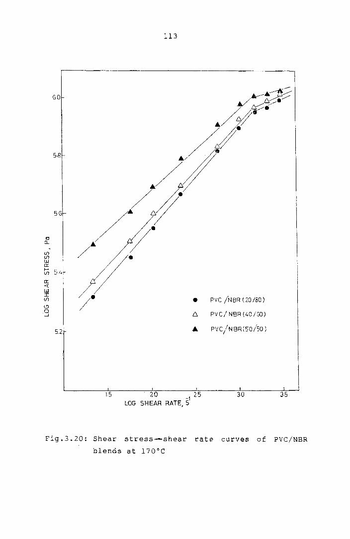
o a..
If) If) w er:
58
I-If) 51:'~
Cl: « w I If)
~ o .....I
5.2
15
113
•
20 I
LOG SHEAR RATE .~} 25 ,
pvc jNBR (20/80)
PVC/ NBR (40/50)
PYC/NBR(S"O/SO)
F' 19.3.20· Sh ear stress blends -shear rate at 1700C curves
of P VC/NBR

114
the same behaviour is exhibited by pvc/NBR blends also.
We could not report the behaviour of NBR alone since the
capi lla ry rheometer, could not handl e t he high vi scos i ty
of NBR alone. The power law indices I a measure of the
pseudoplastic behaviour, calculated as the slopes of the
straight lines below and above the critical shear rates
from Figs.3.18 to 3.20 are shown in Table 3.8.
The t.emperature dependence of the viscosity of
the polymer blends can be expressed by the flow activation
energy calculated from the Arrhenius type equation,
'1 = A.eE/RT
where E is the activation energy for viscous flow, R the
gas constant, T the absolute temperature and A is a
constant. Since the flow behaviour is dependant upon
shear rate and temperature, a plot of viscosity vs
temperature may also reveal the two flow mechanisms shown
by shear stress
are taken over
vs. shear rate plots,
a broad spectrum of
provided the data
31,40 temperatures.
However, the data were taken only at three temperatures in
the present study and the double flow behaviour obviously
will not be revealed. However, if the plot of 'tt vs liT

Tab
le
3.8
: P
ow
er
law
in
dex
v
alu
es
of
PVC
b
len
ds at
170Q
C
CA
PIL
LA
RY
V
ISC
OM
ET
ER
Per
cen
tag
e P
VC
/Hy
trel
PV
C/E
VA
P
VC
/NB
R
To
rqu
e
Rh
eo
mete
r
com
pos i
-P
VC
/ P
VC
/ P
VC
/ ti
on
of
Belo
w
Aft
er
Belo
w
Aft
er
Belo
w
Aft
er
PV
C:M
od
ifie
r cri
tical
cri
tical
cri
tical
cri
tical
cri
tical
cri
tical
Hy
trel
EV
A
NB
R
sh
ear
sh
ear
sh
ear
sh
ear
sh
ear
sh
ear
rate
rate
rate
rate
rate
rate
0 1
00
0
.56
0
.34
0
.42
0
.42
0
.27
0
.28
0
.21
I-
' I-
'
20
8
0
0.5
0
0.3
0
0.3
6
0.2
0
0.4
4
0.1
8
0.2
2
0.2
6
0.1
8
111
30
7
0
0.4
8
0.2
7
0.3
2
0.1
8
0.4
0
0.1
6
0.1
8
0.2
4
0.1
5
40
6
0
0.4
5
0.2
6
0.3
0
0.1
6
0.3
8
0.1
1
0.1
5
0.2
1
0.1
3
50
5
0
0.3
9
0.2
2
0.3
0
0.1
4
0.2
8
0.0
7
0.1
3
0.1
8
0.1
2

116
for a particular blend is drawn for a wide range of shear
rates, the critical shear rate at which the flow mechanism
changes can be observed. Fig.3.21 shows the variation of
viscosity with absolute temperature at different shear
rates for a 30/70 PVC/Hytrel blend. The activation energy
of viscous flow calculated from these straight lines is
shown in Table 3.9.
It can be observed that the flow activation
energy remains more or less the same with marginal changes
when the shear rate varies from 23.0 S-l to -1
576.0 S .
After that there iSQsharp decrease in the flow activation
energy and thereafter remains more or less the same again.
This shows that the critical shear rate for the blend is
around -1
576.0 S . The sharp reduction ln the flow
activation energy beyond this critical shear rate is
obviously due to the highly non-Newtonian behaviour
introduced due to the fusion of PVC . 1 31 partlc es. The
table also shows the flow activation energies of 30/70
bl ends 0 f PVC/EVA and PVC/NBR. In these cases also the
shear rate at which the flow transition occurs can be
observed. Fig.3.22 shows the effect of blend ratio on the
act i va t i on energy of PVC/Hyt reI blends. The activation
energy of PVC/modifier blends at 23.0 S-l shear rate is

117
4.0
/, o 23·05
~ ~ 57·65
3.5 o L CD 115.25
A~ <D
~ () 57G.0 5
-\
.~
.~
2.5
2.0,L--::-::::--_____ ~=_=_------~:-:------------l 2-20 225 2 ·30
1/TxlcrK1
Fig.3.2l: variation of viscosity with temperature at
different shear rates for a 30/70 PVC/Hytre1
blend

118
Table 3.9: Variation of activation energy of pvc blends
with shear rate
Apparent Flow activation energy kJ/mole
shear rate PVC/Hytrel PVC/EVA PVC/NBR (S-l) (30/70) (30/70) (30/70)
23.0 131.5 38.3 50.3
57.6 123.8 33.5 47.8
115.2 123.8 33.5 47.8
230.4 112.5 31.9 40.2
576.0 101. 4 28.7 38.2
1152.0 57.4 28.7 20.1
1728.0 57.4 15.1 19.1
2304.0 47.8 14.9 18.2
2880.0 40.2 9.5 14 . .3

4.0
3.8
3.6
If! c
Cl.. 3.4 ~
>-I-
I.J1 0 U I.J1
> ~ 32 0 .-l
30
2.8
119
0 HYTREL
• PVC / HYTREL( 20 /80)
6, PV C / HYTREL(40 /60)
& PV C / HYTREL (50 ISO)
&
/ C!;
/
/ /0
no J -1
1/TxtU·K
./
6,/
./ ~ /
0
•
0
2·25 2-30
Fig.3.22: Variation of viscosity with temperature for
PVC/Hytrel blends wi th (PVC content)
(at a shear rate of 23.0 s-l)

120
given In Table 3.10. It can be observed from the table
that the flow activation energy decreases with increase of
PVC content.
Table 3.10: Variation of activation energy of PVC blends
with blend composition.
Percentage Flow activation energies at 23.0 S -1
composition shear rate (kJ/mole) of pvc : Modifier PVC/Hytrel PVC/EVA PVC/NBR
0 100 145.8 50.6
20 80 135.4 47.9 56.39
40 60 109.5 35.3 47.8
50 50 94.8 31.9 42.5
Rheological Functions using the Brabender Plasticorder
Fig-3.23 shows the variation of torque/rpm vs r:pm
for: PVC/Hytrel blends at 170°C In the Brabender plast i-
corder:. As in the case of capillary rheometer torque/rpm,
representing viscosity, decreases with increase in rpm
which represents shear r: ate. It lS interesting to note
that even though the shear rates involved are not high,
the behaviour is strongly non-Newtonian and the flow

121
·50
·45
0 HYTREL
·40 6- PVC IHYTREL(20/80)
• PV cl HYTREL(40 /60)
·35 • PVC/HYTREU50/~O)
~ .30 tl. a: "'-
E z w ::J 0 er 0 f-
.25
.20
.15
.10
.05
o 30 50
RPM
• .~ ~4_
6 ._
~~
70 90
Fig.3.23: Variation of Brabender torque/rpm vs rpm for
PVC/Hytrel blends at 170°C

122
behaviour corresponds to that observed above the critical
shear rate in the capillary rheometer.43 However this
behaviour cannot be fully taken as representing the
rheological behaviour of the blends due to lack of
uniformity in shear and temperature in the Brabender
plasticorder. The large initial drop In torque in each
case is probably due to the mechanical degradations
occuring in the melt resulting from the complex shearing
and also due to oxidative degradations to which this
instrument IS more susceptible. There is no sign of zero
shear viscosity in any case.
Brabender plasticorder is not
rheological behaviour of such
This further shows that the
efficient in describing the
two phase melts. The same
behaviour IS observed for PVC/EVA (Fig.3.24) and PVC/NBR
(Fig.3.25) blends.
Fig. 3 • 2 6 s how s the '7 a r i a t ion 0 f log tor que vs
log rpm for PVC/Hytrel blends at 170°C.
each blend can be approximated by a
The behaviour of
straight line,
probably since only a small range of shear rates is
covered in this instrument. The slope of the lines
represents the value of the power law index. Unlike the
behaviour of the melt in the capillary rheometer the melt
behaviour is highly non-Newtonian even at the low shear

0·7
O·G
05
0.4 2: D-o: -E z w 0.3 :::J C1 0: 0 f-
0.2
0.1
"'0
30
123
£::,
o EVA
e PVC/EVA(20/S0)
£::, PV C/E VA (40/60)
.. PVC/EVA(50/S0)
.~~ e- -
o~ 0
'-----0---
50 70 80
RPM
110
Fig.3.24: variation of Brabender torque/rpm vs. rpm
for PVC/EVA blends at 170°C

:2: D.. a::
........
E z w :::::J 0 et: 0 I-
1·0
0.8
0.6
0.4
124
6 NBR
.&. PVC iN8R(20/aO)
o PVC /NBRt40/S0)
• PV C / N BR ( 5015 0 )
6~ ~~~.~ ~~O~
~ --.&.-~6_
0.2~ ______ ~ ________ ~ ________ ~ ________ ~ ________ ~ 30 50 70 90
R PM
Fig.3.25: variation of Brabender torque/rpm vs ~pm for
PVC/NBR blends at 170°C

E z
~
W :::l o a::
1.20r-
1.1Oi-
01.0
125
o HYTREL
• PVC/HYTREL(20/80)
6 PVC!HYTREl(40/so)
A PVC!HYTREL(SO/SO)
----A_ .-A--.----
e 090 t!)
o ..J
---~o
o~o
o~ O.70L--___ ~~ __ ..I._._ _____ __LJ ______ _l.~ _____ ___1
12 1-4 16 1·8
OBOf--
2:0 LOG RPM
Fig.3. 26: Brabender torque-rpm curves for PVC!Hytrel
blends at 170°C

126
rates encountered. This again shows the inefficiency of
the Brabender plasticorder in describing the rheological
behaviour of the complex melts used in the. present study.
The same behaviour is observed for PVC/EVA and PVC/NBR
blends also. The power law indices calculated from the
figures for the blends are given in Table 3.8.
Fig.3.21 show~ the variation of log torque/rpm vs
reciprocal absolute temperatures for PVC/Hytrel blends at
a particular rpm. As observed from the capillary
rheometer data the activation energy decreases with
increase in PVC content.
From the foregoing discussions it is clear that a
Brabender plasticorder is not suitable for evaluating the
rheological functions of a complex two phase melt due to
~he following reasons:
1. only a small range of shear rates is covered
2. lack of uniformity of shear and temperature
3. more suscepLible to oxidative degradations.
Elastic Behaviour of the Blends
The elastic nature of the mel ts was determined
from the entrance pressure loss
ratio D /D. e
P and extrudate swell c

1.0 -
0.9
0.8
~ 0.7 a.. et:
'--... 01 ~
W :::::J 0.6 o et: o I-
0-5
0.4
127
•
°
/ o
o HYTREL
• PVC /HYTREL(20/BO)
6 PVC/HYTREL(40/GO)
A PVC!HYTREL( 50/S0)
0.31-_-L-=O=--___ -'-__ -l-.-_______ --:-l-:-::--____ --:::_::_=_'
2-20 2:25 2·30 2·35
l/Txlcr ~
Fig.3.27: Variation of Brabender torque/rpm wi th
temperature for PVC/Hytrel blends at 30 rpm

128
Experimental
Melt elasticity parameters were evaluated at
The entrance pressure losses (p ) c for the blends
were determined from Bagley plots. Pressure drop (Ap) was
measured at constant shear rates with three capillaries of
constant radius (0.5 mm) but different lengths (10 mm,
20 mm and 30 mm). The measured values of Ap were plotted
against L/R. Linearisation and extrapolation of these
curvesto L/R = 0 gave the entrance pressure loss (P ). c
The extrudate swell ratio was measured as the
ratio of the extrudate diameter (D ) to the capillary e
diameter (D).
Results and Discussion
Fig.3.28 shows the Bagley plot of 50/50
PVC/Hytrel blend at various shear rates. The entrance
pressure losses P at various shear rates were determined c
from this plots. Similarly entrance pressure losses were
calculated for PVC/EVA and PVC/NBR blends. The variation
of entrance pressure loss with shear rate for PVC/Hytrel
blends is shown in Fig.3.29. The pressure loss is
strongly dependent upon the shear rate, as expected. The

100 -
80
o GO a.. 2: 0.. ... <l a.. o Cl: o
~ 40 ::J lfl lfl lJ.J er: a..
o
129
20 40 60 L/R
Fig.3.28: 8agley plot of (50/50) PVC/Hytrel blends at
various shear rates
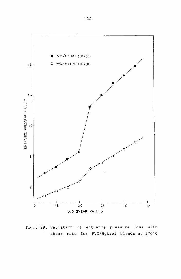
, 8 f-
'4f-u
U. , (/) (/)
0 .....J
W et: :::l (/)
U1 w 10 et: a.. w u z <.( et: f-Z w
6
z
o
130
• PVC / HYTREL (50 ISO)
o PVC/ HYTREl(20 (80) /
.// ./
/ e·
I t I I
2·0 2·5 30
lOG SHEAR RAT~ ~
1
35
Fig.3.29: Variation of entrance pressure loss with
shear rate for PVC/Hytrel blends at 170°C

131
pressure loss is found to vary smoothly and mildly between
-1 -1 the shear rates 23.0 Sand 230.0 S • After this, there
is a large increase in pressure loss and thereafter there
is only a mild variation. The transition may be the
region at which large scale fusion of PVC particles takes
place. This 1S similar to the flow mechanisms shown by
PVC blends (Fig.3.18). Similar variation in entrance
pressure loss 1S observed for PVC/EVA (Fig.3.30) and
PVC/NBR blends.
Fig.3.31 shows the variation of entrance pressure
loss with PVC content for PVC/Hytrel blends. In the low
shear region the elastic effects are found to 1ncrease
with PVC content upto about 40% PVC and thereafter
decrease. However, this decrease 1n the elastic effects
with PVC content proba b 1 Y resul t s from the improper
fusion of PVC particles, since at higher shear rates, the
elastic effects again increase with PVC content. Th is is
in conformity with earlier observations. Similar
behaviour is shown -by PVC/EVA (Fig.3.32) and PVC/NBR
blends.
Figs.3.33 and 3.34 show the variation of
extrudate swell ratio with blend composition at different

132
'2
• PVC/EVA(40/GO)
o PVC IEVA (20/80)
10
u 8 Q . (j)
§ w a: :::J (j) (j)
w a: 6 a... w u Z <l: 0: r-Z t1.l
4
to '·5 20 25 ),0 J5
LOG SHEAR RATE J S1
Fig.3.30: Variation of entrance pressure loss with
shear rates for PVC/EVA blends at 170°C
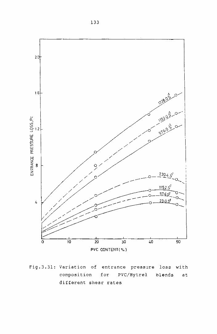
u 0....
Vl Vl
20
1 G
3'12
w 0: ::J If) U1 W 0:: 0....
~ Z
~ 8 fZ W
4
o 10
133
o
1152 SI o _ O __ :U§$l 0--..
- --0 __ 23·09 .....
-0 ............. o
20 30 40 50
pvc CONTENT( 0'0)
Fig. 3.31: Variation of entrance pressure loss wi th
composition for PVC/Hytrel blends at
different shear rates

134
12~----------------------------------------~--~~~~
10
u 8 Q
, If) If) o -.J
w er: :::J If)
If) G w a: Q
w U Z ~ er: !z w t.
2
o
~-----O
_______ 0
--
10 ·20 30
PV C CONTENT ( 0,. )
-1 0_-2304.05 0 ------
40 50
Fig.3.32: Variation of entrance pressure loss with
blend composition for PVC/EVA blends at
different shear rates

0 -~ 0
, 0 f-<{ er _1 _J W
~ w f-<{ 0 ::J Ir: f->< W
135
1·4
1·3 -
1·2 -
11
10 o
o 2305'
Cl 5765'
() "525'
6. 23045'
0·8 ... 57605'
o 10 20 30 40 50
PVC CONTENT(·I.)
Fig.3.33: Variation of extrudate swell ratio with
blend composition for PVC/Hytrel blends at
different shear rates

1.7
1.6
o '-. 1.5 t.l o
o j::: ~ Cl:
...J
...J W
~ w ~ ~ a EE 1.3 lx W
136
0 23.05'
• 57.651
6- 115.251
at. 2304 '5}
. --------------~ --- • A-1\ f:::. -
• ~6-
--------.------------------.---------.-0
0-0--
o 10 20 30 40 50
PVC CONTENT ("I.)
Fig.3.34: Variation of extrudate swell ratio with
blend composition for PVC/EVA blends at
different shear rates
137
shear rates for PVC!Hytrel and PVC!EVA blends. Extrudate
swell increases with shear rate in all cases as expected.
As in the case of the entrance pressure loss I the die
swell ratio also increases with PVC content. This further
confirms the higher elastic nature of PVC in melts
compared to Hytrel, EVA and NBR. The higher elastic
recovery of PVC compared to other polymeric additives such
as Hyt reI and epox idi zed na t ural rubbe r has a I ready been
44,45 reported.
138
REFERENCES
1. A.A.Kanauzova, T.S.Khodosh, A.A.Dontsov and
T.D.Mallchevskaya, Int. Polym. Sci. Technbl. 15 (4)
T/22 (1988).
2. K.Mori and Y.Nakamura, Plast. Rubb. Process. Appl. 3
(1) 17 (1983).
3. P.J.Corish, Polymer Blends and Mixtures, D.J.Walsh,
J .S.Higgins and A.Maconnachie, (Eds), Martinus Nijhoff
Publishers, pp.453 (1985).
4. W.H.Hofmann, Rubber Technology Handbook, Hanser
Publishers, p.294 (1989).
5. G.H.Hofmann, Polymer Blends and Mixtures, D.J.Walsh,
J .S.Higgins and A.:1aconnachie, (Eds), Martinus Nijhoff
Publishers, p.117 (1985).
6. J.T.Lutz, Degradation and Stabilisation of PVC,
E.D.Owen (Ed), Elsevier Applied Science Publishers,
p.253 (1984).
7. L.A.Utracki, Polym. Plast. Technol. Eng. 22 (1) 27
(1984).

139
8. L.M.Robeson, Polym. Eng. Sci. 24 (8) 587 (1984).
9. Y. Nakamura, K. Mori and R. Takesawa, Int. Polym. Sci.
Technol. 7 (7) T/9 (1980).
10. K.E.George, R.Joseph and D.J.Francis, Die. Ang.
Makromol. Chemie. 153 153 (1987).
11. D.R.Paul and S.Newman (Eds), Polymer Blends, Academic
Press, 1, Chapter 6 (1978).
12. J.A.Manson and L.H.Sperling, Polymer Blends and
Composites, Plenum Press (1976).
13. O.Olabisi, L.M.Robeson and M.T.Shaw, Polymer-Polymer
Miscibility, Academic Press, Chapter 6 (1979).
14. M.Xanthos, Polym. Eng. Sci. 28 (21) 1392 (1988).
15. A.Y.Coran and R.Patel, Rubb. Chem. Techno1. 56 (5)
1045 (1983).
16. C.Qin, J.Yin and B.Hueing, Polymer, 31 663 (1990).
17. J.Heuschen, J.M.Vion, R.Jerome and P.Teyssie, Polymer
31 (8) 1473 (1990).

140
18. W.J.Ho and R.Sa1ovey, Polym. Eng. Sci. 21 839 (1981).
19. R.C.Thamm, Rubb. Chem. Technol. 50 24 (1977).
20. C.S.Ha, J. Appl. Polym. Sci. 35 2211 (1988).
21. S.Danesi and R.S.Porter, Polymer 19 448 (1978).
22. Tom Hawkins, J. Vinyl Tech. 4 116 (1982).
23. w.V.Titow, PVC Technology, Elsevier Applied Science
Publishers, Chapter 9, p.256 (1984).
24. Dietrich Braun and Eugen Bezdadia, Encyclopedia of
PVC, Leonard I .Nass I Charles A.Heiberger, (Eds) I I,
Chapter 8, p.398.
25. W.S.Penn, pvc Technology, Applied Science Publishers,
London, p.195 (1971).
26. K.E.George, R.Joseph and D.J.Francis, Plast. Rubb.
Process. Appln. 5 2 (1985).
27. D.J.Dunne, Plast. Rubb. Process· Appln.
(1983).
3 (4) 337

141
28. K.E.George, R.Joseph and D.J.Francis, J. Appl. Polym.
Sci. 32 (1) 2867 (1986).
29. K.E.George, R.Joseph and D.J.Francis, Polym. Eng. Sci.
27 (15) 1137 (1987).
30. J.R.Wolfe, Thermoplastic Elastomers, N.R.Legge,
G. Holden and H. E. Schroedu , ( Eds), Hanser Publ i shers ,
p.117 (1987).
31. C.L.Sieglaff, Polym. Eng. Sci. 9 81 (1969).
32. J .A.Br,Ydson, Flow Properties of Polymer Melts, second
edition, George Godwin Ltd., London, Chapter 3 (1981).
33. Karl-Heinz Moos, Goettfert Werkstoff-Prufmaschinen
Gmbit, Buchen FRG, Proceedings of the Second
Conference of European Rheologists, Prague (1986).
34. B.Rabinowitsch, Z. Physik. Chem. A145 1 (1929).
35. E.B.Bagley, J. Appl. Phys. 28 557 (1957).
36. Z.Bartha, P.Erdos and J.Matis, Int. Polym. Sci.
Technol. 10 (6) T/50 (1983).
142
37. R.A.Mendelsen, Polyrn. Eng. Sci. 8 235 (1968).
38.T.M.Baek, K.H.Chung and R.Salovey, J. Vinyl Tech. 3
(4) 208 (1981).
39. Z.Du and S.Zaijian, Plast. Rubb. Process. Appln. 7 (4)
229 (1987).
40. E.A.Col1ins and A.P.Metzger, Polyrn. Eng. Sci. 11 446
(l971).
41. U.K.Saroop, K.K.Sharrna and K.K.Jain, J. Appl. Polyrn.
Sci. 38 1421 (1989).
42. J.Francis, K.E.George and D.J.Francis, Kautschuk Gumrni
Kunststoffe 43 (3) 193 (1990).
43. J.E.Goodrich and R.S.Porter, Polyrn. Eng. Sci. 7 45
(1967).
44. K.T.Varughese, P.P.De and S.K.Sanyal, J. Vinyl Tech.
10 (4) 166 (l988).
45. S.Thomas, B.Kuriakose, B.R.Gupta and S.K.De, Plast.
Rubb. Process. Appln. 6 (1) 85 (1986).

Chapter 4
STUDIES ON POLY(VINYL CHLORIDE)/UNEAR LOW DENSITY
POLYETHYLENE BLENDS

STUDIES ON POLY{VINYL CHLORIDE)/LINEAR LOW DENSITY
POLYETHYLENE BLENDS
The widespread development of plastics and
plastic products all over the world has also brought it
with a huge problem. Plastics, today form a sizable
fraction of solid wastes, a large portion of which are
commodity plastics. Their lack of biodegradability 1S
generating new problems such as lack of landfill sites,
growing water and land surface litter etc. Recycling by
reprocessing of plastic waste 1S a solution to the major
problem created by the plastic consumer society. This
method of reutilisation of solid plastic waste is used as
a base for producing secondary products, lowering energy
costs, and reducing environmental pollution. Also :.he
increase in the price of polymeric raw materials is making
the recycling of consumer waste to secondary produc:.s
attractive. Polyethylene 1S a major component of the
plastic waste. Eighty per cent of the polyethylene waste
is con t amina t ed wi th other polymer s 1 ike pol ypropy 1 ene ,
1-3 polystyrene, poly(vinyl chloride) etc. However,
separating these polymers and then recycling them
individually, introduces an addition costly step in the
143

144
reprocessing route. Instead, reprocessing of the mixed
plastic waste is becoming more popular ln view of the
economic benefits.
Several researchers have studied the blends of
low density polyethylene (LDPE) with polystyrene (PS), 4.5"
high density polyethylene (HDPE) and polypropylene (pP).
Mikkonen et 2 al. studied the rheological, morpho-
logical and mechanical properties of the LDPE/plasticised
PVC blends. The PVC/PE blend is now utilised in several
applications like blister packaging, low halogen-low smoke
fire resistant electric cable sheathing etc. 6,7 Many of
the problems associated with recycling of mixed plastic
wastes are identifiable in the processing/reprocessing of
PVC/PE mixtures. Processing of the PVC/PE mixtures is not
likely to yield products with the expected mechanical
properties because of the poor adhesion of the phases due
d " "b'l' 8-10 to the thermo ynamlc lncompatl 1 lty. In literature,
various methods have been suggested for the reactive
compatibilisation of such immiscible blends for demanding
applications. The mechanical properties and the technical
performance of the immiscible blends would be more nearly
additive if the interfacial zone is strengthened. One way
to do this is to add interfacially active agents to the

145
immiscible " 8,10 m1xture. Thus the interfacial energy
between the immiscible phases is reduced ensuring a finer
dispersion upon mixing and higher stability against phase
" f "b"l" 11 separat1on. Most common types 0 compat1 1 1sers are
1. block, graft or random copolymers
2. co-solubilisers enhancing the interpenetration of
resin domains
3. co-reactors, catalysts enhancing chemical reaction
between the resins
4. modifications or additives enhancing specific
interactions.
In the present study an attempt 1S made to
modi ft _ the immiscible PVC/PE blend by various methods
listed above. The polyethylene selected for the study is
the newest member of the polyolefine family viz., linear
low density polyethylene (LLDPE), since it is fast
replacing low density polyethylene (LDPE) in many
applications. LLDPE has a greater degree of stiffness and
higher tensile strength than LDPE and also has a more
regular crystalline structure, higher melting point and a
better fracture resistance at low temperature. Coupled
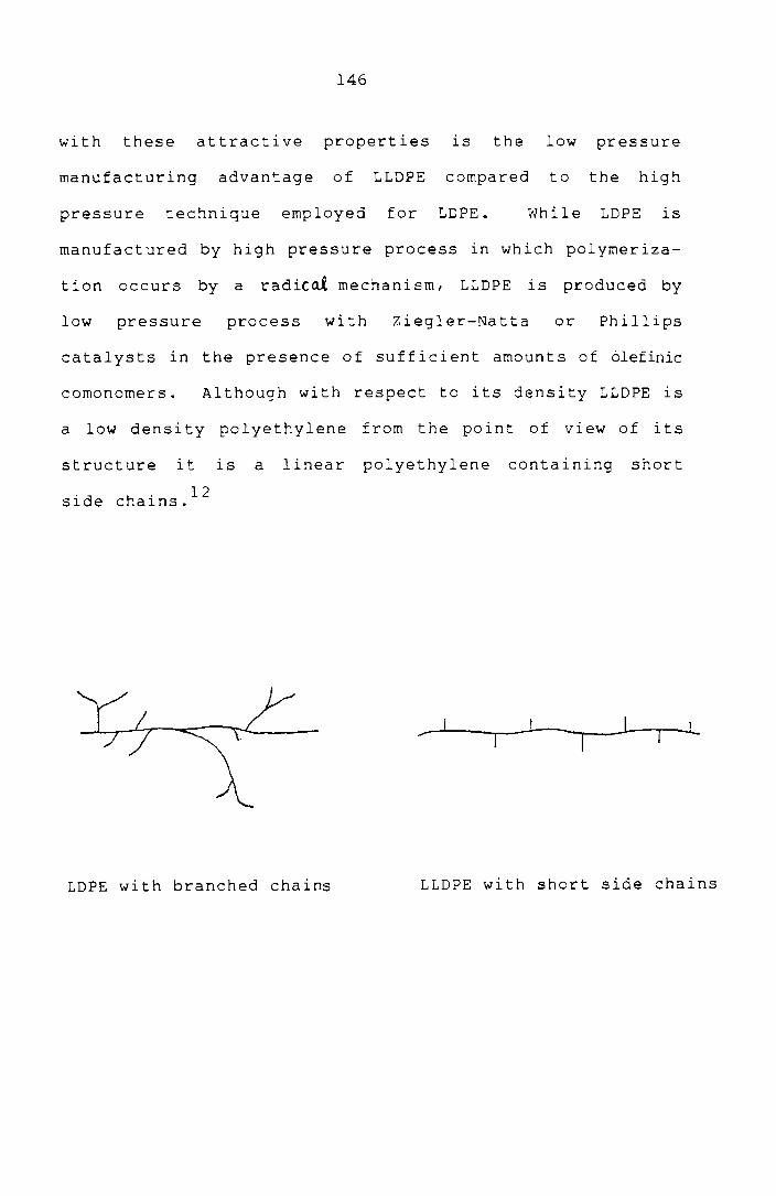
146
with these attractive properties is the low pressure
manufacturing advantage of LLDPE compared to the high
pressure technique employed for LDPE. While LDPE is
manufactured by high pressure process in which polymeriza-
tion occurs by a radiCol mechanism, LLDPE 1S produced by
low pressure process with Ziegler-Natta or Phillips
catalysts in the presence of sufficient amounts of olefinic
comonomers. Although with respect to its density LLDPE is
a low density polyethylene from the point of view of its
structure it is a linear polyethylene containing short
. d h' 12 Sl e c a1ns.
...-_...l...-_~.J---~ __ I _JJ---,.--L
LDPE with branched chains LLDPE with short side chains

147
CHLORINATED POLYETHYLENE (CPE) AS A MODIFIER
FOR PVC/LLDPE BLENDS
Block and graft copolymers with the segments or
blocks chemically identical or similar to the components
of the blend have been found to be the most useful to act
as compatibilising agents. Since vinyl chloride can only
be polymerised by a radical mechanism, production of block
copolymers of PVC is difficult and a constitutive block
miscible with PVC is the only alternative 13
me.t hod.
Chlorinated polyethylene, a block like polymer with
segmented structure, has been suggested as a compati-
biliser for HDPE/PVC and PS/PVC . 14
mlxtures. Bataille et
al. lS have studied the influence of CPE, EVA etc. on the
physical and processing properties of LDPE/PVC mixtures.
Also the ability of block chlorinated polyethylene to
improve the ductility of blends of LDPE and PVC has
previously been reported by Locke 16
and Paul. Hence in
the present study, CPE is selected as the modifier for
PVC/LLD PE bl ends. In PVC blends, the improvement in the
fusion state of PVC is found to be one of the mechanisms
by which the modifiers act (previous chapter). Hence
PVC-l with a lower molecular weight was chosen for
modification by CPE since it is easier to achieve a better
fusion state with a PVC grade of lower K value.

Experimental
Polymer blends
plasticorder equipped
148
were
with
prepared on a
roller blades.
Brabender
Mixing
conditions were 170°C and 30 rpm. LLDPE was added first,
then CPE and finally PVC along with its heat stabiliser
(4 phr tribasic lead sulphate). Samples were prepared by
compression moulding at 180°C for 3 minutes. The tensile
properties of the blends were determined according to
ASTM D 638 on a Zwick universal testing machine using a
cross head s~eed of 50 mm/min.
Results and Discussion
Fig.4.1 shows the effec~ of adding CPE (10 parts
per 100 parts of PVC and LLDPE) on the tensile properties
of PVC-l/LLDPE-l and PVC-l/LLDPE-2 blends. The tensile
properties of the unmodified PVC/LLDPE blends are far
below the expected average values of tensile strength.
This result is probably due to the incompatibility of the
constituents resulting from large differences in the
polarity and crystallinity, and hence their incapability
to combine the properties of the constituent polymers. A
second reason specific to this blend might be the state of
fusion of PVC particles in the blend, since it has a
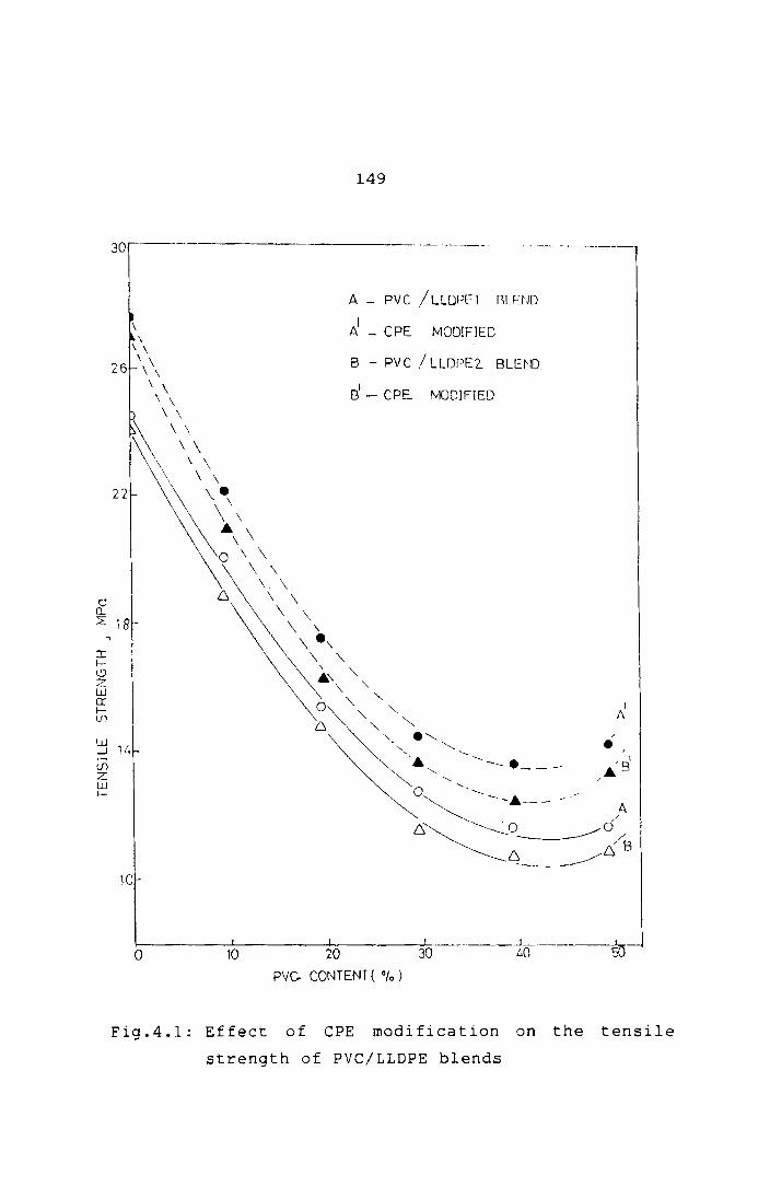
149
30 ------------ .-----.. - .. -----
o n..
22
\ \ \ \ \ \ \
\ \ \ \
\ '\
~ \ \
\ \\ '\\ \ \
\~e\ \ \
~:\\\ \ \
\. \ 6 \ \
\ \ \ \ ::?: 18-
::r: f(.9 Z W er: fU)
\ e\ '\ '\
A - PVC /LLOPFl r.U-]J[]
d - (PE MODIFlED
B - PVC / LUWE2 SLEm
Si _ CPE fvKJOIFIED
I 1\
::J 1 t. (/)
• I
I I
,6.8 Z W 1-
/
10
1-------'-----_---I. ____ ---L,-.. __ . __ . .J_. ______ ---1....
10 20 30 LO 50 o PVc. CONTENT ( "la )
Fig.4.l: Effect of CPE modification on the tensile
strength of PVC/LLDPE blends

150
distinct structure of primary particles different from
other commodity
17-20 styrene.
plast ics such
PVC-l/LLDPE-l
as polyethylene or poly-
shows marginally better
strength than PVC-l/LLDPE-2 blends. This might be due to
the better molecular weight/viscosity matching of the
PVC-l and LLDPE-l grades than tha t of PVC-l and LLDPE-2
blends. Also it seems to be more sensitive to the
addi tion of CPE. Hence further studies on CPE modifica-
tion have been done on PVC-l/LLDPE-l blends.
The effect of three grades of CPE (all grades
added at a concentration of 10 parts per 100 parts of PVC
and LLDPE) in improving the tensile strength of PVC/LLDPE
blends is shown in Fig.4.2. While all the three grades
are success ful in br i ng i ng about some improvement in the
strength, CPE-l is the best showing that it has the ideal
molecular weight/viscosity characteristics to emulsify the
PVC/LLDPE blends. Hence CPE-l was chosen for further
studies.
Fig.4.3 shows the effect of the variation of CPE
content on the tensile strength and elongation at break of
50/50 PVC/LLDPE blends. It is found that increasing the

o a... 2:
.,
30-·'
22
~ 18-t.9 :z w 0: f-(j)
W ...J
lfi z ~ 1/,
10
151
A - ePEl MODIFIr:D
8 - CPE2 tv1ODJr-IED
C _ CPE3 MODIFIED
o - l}\JM)~FIED
~------~--------~ ________ -L _________ L---_____ ~ o m w ~ ~ ~
PVC CONTENT ( %)
Fig.4.2: Effect of different types of CPE on the
tensile strength of PVC/LLDPE blends
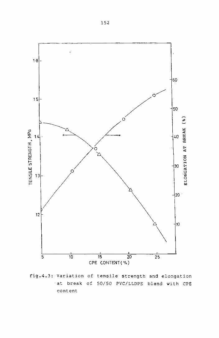
152
1 G -
60
0/ 15-
/ 50
....... 0 Of' -----Cl ........... 6 ::G
.et a.. ~ 2: 14 - 40 0::
:x: III
l- 0 ~ ~ .cl; Z ~ W z er:: 0 t- H lJ'l 30 ~ w
0 .cl;
....J l!) Vi 13 'z z 0 W ...:I !- tzJ
20 '
12
6. 10
\ 5 10 15 20 25
ePE C.ONTENT( Oh)
Fig.4.3: Variation of tensile strength and elongation
'at break of 50/50 PVC/LLDPE blend with CPE
content
153
amount of CPE steadily improves the elongation at break of
the blends while the tensile strength falls. A compromise
has to struck for overall improvement in mechanical
properties. Ten per cent by weight of the total polymer
is taken as the optimum CPE concentration Slnce the
tensile strength does not start falling sharply at this
concentration. CPE concentration was fixed at this level
for further studies.
Morphological Studies
The morphology of the blends was investigated
using an opt i ca I mi croscope. The sur face morpho logy 0 f
the blends observed with the optical microscope at a
magnification of 330 is shown in Figs.4.4 to 4.7. As is
evident from the photograohs the morphology of the
different systems varies with composition. CPE modifica-
tion makes a more regular and homogeneous distribution of
the dispersed phase of the PVC/LLDPE blends. All the
morphological observations are in accordance with the
tensile properties of these blends. The CPE modified
blends show improved mechanical strength because of the
better co-continuous nature of the phases permitting stress
transfer of the components across the interface.

r
Fig
.4.4
2
0/8
0
PVC
/LL
DPE
b
le
nd
(un
mod
if
ied
) F
ig.4
.5
20
/80
PV
C/L
LD
PE
bl
end
(C
PE
m
od
ifi
ed
)
Op
tica
l m
icro
sco
pe
ph
oto
gra
ph
s o
f th
e
PVC
/L
LD
PE
ble
nd
s
... '" ..

Fig
.4.6
4
0/6
0
PVC
/L
LD
PE
ble
nd
(u
nm
od
ifie
d)
Fig
.4.7
4
0/6
0 PV
C/L
LD
PE
ble
nd
(C
PE
m
od
ifie
d)
Op
tica
l m
icro
sco
pe
ph
oto
gra
ph
s o
f th
e
PV
C/L
LD
PE
b
len
ds
... '" '"

156
Processability Studies
Investigation of the rheological pro!?erties of
the mixtures was done to assess their behaviour during
melt processing. Moreover, the rheological properties of
the mixtures permit the study of the structure of the
It 21-24
me s. The effect of CPE on the melt viscosity and
melt elasticity of PVC/LLDPE blends is investigated.
Experimental
Me 1 t rheo log i cal propert i es were measured on a
capillary rheometer (Goettfert visco-tester 1500) using a
capillary die of circular cross section (length 30 mm
diameter 1 mm) over a wide range of shear rates at 160,
170, 180 and 200°C. Apparent viscosities and shear rates
were calculated according to Hagen-Poiseuille law. The
true values of shear stress, shear rate and viscosity
were ca lcula t ed by correct i ng the appa ren t val ues. Th e
true shear rate (Yw
) was calculated by applying the
Rabinowitsch correction according to the equation. 23
"( w = ( 3n + 1) -(,
4n wap!?
where the In' values were determined as the slo!?es of the
shear stress-shear rate flow curves at different points.
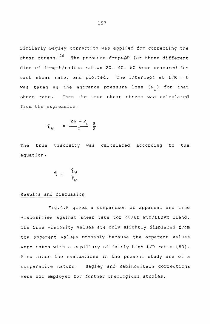
157
Similarly Bagley correction was applied for correcting the
28 shear stress. The pressure drops~ for three different
dies of length/radius ratios 20, 40, 60 were measured for
each shear rate, and plotted. The intercept at L/R = 0
was taken as the entrance pressure loss (p ) c for that
shear rate. Then the true shea r st ress was ca 1 cula ted
from the expression,
1 w = .op - Pc R
L 2"
The true viscosity was calculated according to the
equation,
'1 =
Results and Discussion
Fig.4.8 gives a comparison of apparent and true
viscosities against shear rate for 40/60 PVC/LLDPE blend.
The true viscosity values are only slightly displaced from
the apparent values probably because the apparent values
were taken with a capillary of fairly high L/R ratio (60).
Also since the evaluations in the present study are of a
comparative nature, Bagley and Rabinowitsch corrections
were not employed for further rheological studies.

158
4.0
tJ)
t1 Q..
3.6
3.2
o APPAHENT VISCOSITY
[:}. TRUE VISCOSITY
'12·8 ~ l-V) o u If)
> l!) o ...J
24
20
16~ ________ ~~ ________ ~~ ___________ L-__________ ~
10 2(J 30 40
LOG SHEAR RA lE J ~" 50
Fig.4.8: Comparison of appar-ent and tr-ue viscosities
with shear- r-ate (curves) for 40/60 PVC/LLDPE
blend

159
Fig.4.9 shows the variation of viscosity (l!) of
the blends with blend composition at 170°C, at different
shear rates. Since the dependence of viscosity on
composition is essentially linear at low and high shear,
it may be concluded that there is no substantial change in
the structure of the melt for the composition range
studied. At higher shear rates, th~ straight lines
becomef almost parallel to the X-axis obviously because of
the higher pseudoplasticity of PVC. When CPE is added it
enhances the viscosity of the system, particularly at
lower shear rates. This effect may be due to the
interactions which contribute towards increasing the
strength of the blenos. At higher shear rates I this
effect is not so pronounced suggesting that better
properties can be obtained mechanical compati-
bilisation of the blends at high shear. Large increase in
torque values is also observed for a CPE modified .
PVC/LLDPE blend compared to unmodified PVC/LLDPE blend
d u r i n g Bra 1. end er she a r m i xi n g ( Fig. 4 • 1 0 ) • This result
also suggests strong interactions among the constituents
at low rates of shear. 25 ,26 Figs.4.11 and 4.12 show the
viscosity-shear rate curves of PVC/LLDPE and CPE modified
PVC /L LDPE bl ends. The strong non-Newtonian behaviour of
the blends at higher shear rates is evident from these
figures.

t/)
cP '\
>-l-t/)
0 u Vl
> ~ 0 ---.J
4,0
3.6
3·2
2.8
160
---- ePE MODIFIED
UNMODIFIED
_,. A-"'_---A-23.045 ----h.-----~ ~
---~=.-- t1 ~-~ __ -3-
57.65 () ___ - - -<)_.- _. ()_
() - - - - -- () -=-- ()- ~- -.....& ----A\-- - -!- - - - --1- ---- Lh.- '~5'2 s' ' J.\
230.L.S' ---~-- - --~-- --- -$- -- - -$=--
576,()S' A t .f. _____ ._ -- -.- - - --- -----I A
1152.0 S' -- - -~- - -- ---~- '-- - --~- - - - -'-Z1-~ 1728.0 S'
2,4 - ---1--- - - --1-- -- -- -I------I=. ----g-~- - ---8-------8---- - -:B=-
2304.0 S'
20 30 40 50 PVC, COtHEN T (010)
Fig.4.9: viscosity of the PVC/LLDPE blend as a function
ef composi t i cn at d if fe reo t sbea r rates at 170<':

E
z ~
tll
:..::.> o c:::
o f-
B G
~ ~
C P
E
MO
DI F
lED
~---
----
----
----
----
UN
MO
DIF
IED
2
, ~
o 2
4 6
~
TIM
E(
MIN
)
Fig
.4.1
0:
To
rqu
e
cu
rves
of
the
ePE
m
od
ifie
d
50
/50
P
VC
/LL
DP
E
ble
nd
s
an
d
un
mo
dif
ied
f-'
(J'I ......
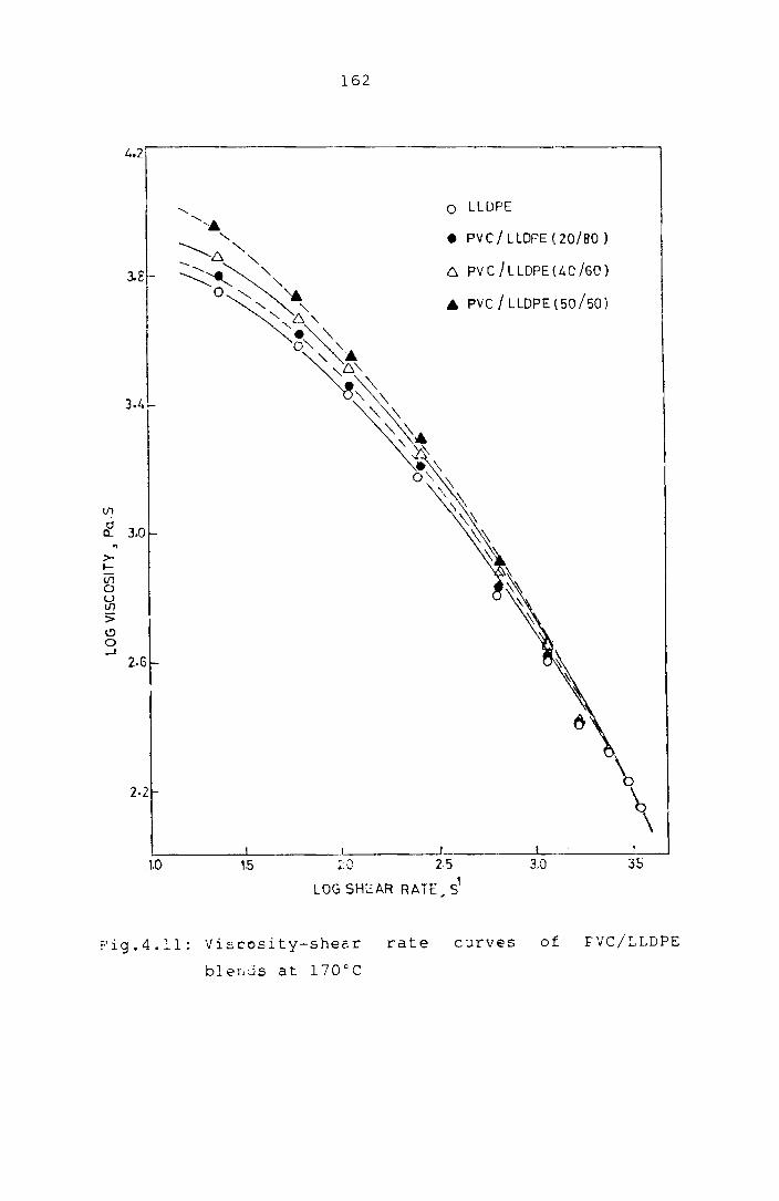
V1
Cl c....
" >-t--Ul 0 U If")
:; 19 0 -I
162
4.2 i' -------------------------------.
o LLDPE
• PVC/LLDPE(20/S0)
3.£ 6. PV C /L LOPE (" 0 /60)
I A PVC/LLDPE(50/50)
J 3.0
2.6
2·2 \ \
'-:-___ --'-__________ L ____ --'--____ LI _..J
1.0 1.5 :: ,J 2.5 3.0 35
LOG SHeAR RATE, S'
Fig.4.11: Viscosity-shear rate curves of FVC/LLDPE
bler.Js at 170°C
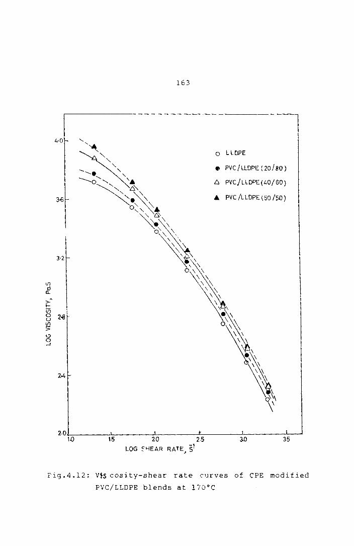
163
4-0
o l LOPE
• PVC /LlOPE ( 20180 )
6 PVCjLLOPE(40/GO)
A PVC /LLOPE (50/50)
2.0J.--__ -.l. ____ -L ____ -L-___ ---J. ____ --'----'
1.0 1·5 20 2·5 3.0 35 LOG ~~EAR RATE S'
J
Fig.4.12: V1s cosity-shear rate curves of CPE modified
PVC/LLDPE blends at 170°C

164
Fig.4.13 shows the flow curves of typical blends
at 170°C. It is interesting to note that the flow curves
of the unmodified and modi fied blends show some
distinctive features. The unmodi f ied blend curve can be
approximated as three straight lines. These straight
lines may indicate different polymer melt structures and
the fusion of PVC particles may be the key factor in
deciding the melt structure. The initial straight line
may indicate a flow behaviour where PVC particles remain
largely unfused, while the intermediate region, a region
of shear where most of the fusion takes place, and the
final straight line may be the normal melt behaviour of
the blends. The intermediate region is not so pronounced
and may be absent for CPE modified blends supporting the
earlier proposition that CPE improves the fusion behaviour
of PVC particles. This effect can be further observed
from Fig.4.14 which is a plot of log "1 vs liT for a 20%
PVC blend at different shear rates. The slopes of these
curves are proportional to an apparent activation energy
for viscous flow. The activation energy has considerable
practical importance because it expresses the temperature
dependence of viscosity of the material. The acti' ation
energies calculated from the slopes of the lines are shown
in Table 4.1. The lower activation energies obtained from

5·7
5.6
5.5
o a.. 5.4 1./"--If'I W c:: l-t!)
Cl: <t 5·3 w :r: If)
I!> o -1
165
~~/ .. /~3~9~/.o/v LA--;:/ O~/
4 ",::"~~Ci ____ /,(J~'" lY.?---". ___ // i •
/l/w1A: / /---------/ / /
/~/ 6/ I ~ 0 A PVC I LLDPE(20/S0)
/ I I
/ / / / I.. /
/ / I cl
I r I J I /
AI ePE MODIFIED
B pveiLLDPE(40/60)
S' CPE M:>DlFIED
e pvcl LLDPE(50/50)
C' CPE MODIFIED
1/ 1;/ / 5.2 . C!(J /
III / Cl. / al / /
5.1 / /~/ 8 . 0
A I /1 A
1.5 2.0 2·5 3.0 3·5 LOG SHEAR RATE~ S1
. Fig.4.13: Shear stress--shear rate curves of modified
and unmodified PVC/LLDPE blends at 170DC

166
4.0
3.5
tIl
/, () 57G.O 5
~ 3.0 '\
> ~
in o U IJ1
> l!) o ....J
-1
A~ .~ ..
2.5 • b.~ --. ~---.~ ______ ~=__________O 2880.05' ______________ 0
--6 ______
-0
2.0._ ............ _______ ~--------~-----~ 2·,0 2-25 2 ·30
l!TxlrY Kl
Fig.4.14: Variation of viscosity with temperature of
20/80 PVC/LLDPE blend at different shear
rates

167
Table 4.1: Variation of flow activation energies of
Shear rate S-l
23.0
57.6
115.2
230.4
576.0
1152.0
1728.0
2304.0
pve/LLDPE blends with shear rate
20 per cent pve/LLDPE blend
Unmodified ePE modified kJ/mole kJ/mole
22.4 19.3
19.3 15.2
16.9 14.4
14.4 11.5
10.9 6.3
9.1 5.8
8.6 5.5
8.3 5.3
ePE modified blends show that ePE is an active flow
improver. Further, it seems that, for each blend at a
particular temperature, there is a particular shear, which
exhibits a transition from one melt structure to oth~r.
Figs.4.15 and 4.16 show the plots of log
viscosity vs liT for the pve/LLDPE and ePE modified
~VC/LLDPE blends at a particular shear rate. The
activation energies calculated fr(~ the slopes of the
straight lines are shown in Table 4.2. It can be observed

3.7
If)
d D...
~
>- 3.5 ~
Ln 0 U lfl
> ~ 0 .J
3.3 -
3,1 r-
!
no
168
I
n5 '/h1C' 1~1
0 LLDPE
• PVC /l LDPE( 20 /80 )
t::. PVC/LLDPE (40/60)
.&. PVC /L LOPE ( 50 /50 )
2,J0
Fig.4.15: variation of viscosity with temperature
of PVC/LLDPE blends with blend composi
tion at a Ehear rate of 23.0 8-1

If'1
d 0...
>-I-
4.2 -
4.1
4.0
(/)1 o 3.8 u If'1
>
8 -'
3.7
3.6
3·5 2-20
169
o LLDPE
• PVC/LLDPE(20/80)
b. PVC /LLDPE (40/60)
A PVC/ LLDPE (50/50)
2·25
,/r x 103 ~' 2-30
Fig.4.16: Variation of viscosity with temperature of
ePE modified PVC/LLDPE
composit.io:1 at a shear
!:,'1ends
rate
",ith b1E':nd -1 of 23.0 S

170
Table 4.2: variation of artivation energy of the PVC/LLDPE
blends with blend composition
Activatjon energy at a shear rate Percentage of 23.0 S-l comROsition of pvc : LLDPE Unmodified ePE modified
kJ/mole kJ/mole
0 100 23.94 19.15
20 80 19.14 17.23
40 60 17.42 15.11
50 50 13.40 10.44
tha t, the f low act i va t i on energy decreases wi t h increase
in PVC content. Also, CPE modification reduces the flow
activation energy of the blends, in all the cases.
Melt Elasticity
The melt elasticity of the blends was measured
from the extrudate swell ratio, D /D.22/24/27 e The
extrudatc. emerging frorr the capillary was collected and
the di2meter of the E:xtrudate was measurEd at. various
points. The extrudate swell ratio wns calculated as the
ratio of the diameter ef the extrud~te D to the diameter e
of the capillary die D.
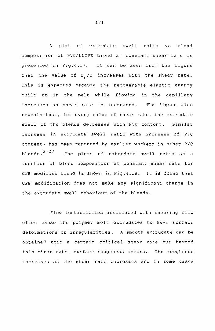
171
A plot of extrudate swell ratio vs blend
composition of PVC/LLDPE b.Lend at constant shear rate IS
presentee in Fig.4.17. It can be seen from the figure
that the value of D /D e increases with the shear rate.
This is expected because the recoverable elastic energy
built up In the melt while flowing In the capillary
increases as shear rate is increased. The figure also
reveals that, for every value of shear rate, the extrudate
swell of the blends decreases with PVC content. Similar
decrease in extrudate swell ratio with increase of PVC
content, has been reported by earlier workers in other PVC
bl d 2,27
en s. The plots of extrudate swell ratio as a
function of blend composition at constant shear rate for
ePE modified blend is shown in Fig.4.18. It is found that
ePE modification does not make any significant change in
the extrudate swell behaviour of the blends.
Flow instabilities associated with shearing flow
often cause the polymer melt extrudates to have sLlrface
deformations or irregularities. A smooth extrudate can be
obtaine''l up:.o a certai" critical shear rate but beyond
this shear rate, surface roughness occurs. The roughness
increases as the shear rate increases and in some cases

o
--tJ
,·6
'·5
1'"
o 1.3 , o ~ a: -l -l W
~ W I<t o ::J er. ~-x w 1.1-
I-a
o
172
o
10 20 38 40 50
pvc CONTENT ('/.)
FiS.4.17: variation of extrudate s~ell ratio with blend
composition of PVC/LLDPE blends at different
shear rat~s
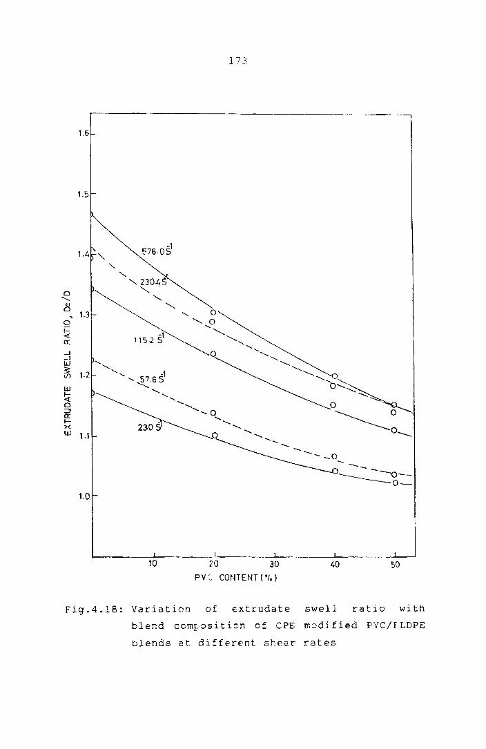
173
r---------------------------------------------------------__ ~ 1.6
1.5
Cl '-8
~ 1.3 0 1= <t ex: ---I ---I W
~ W I-et 0 :;) 0: l-X W , .,
- --_____ 0--0-
1.0
10 20 30 40 50
PVC- CONTENT(O,.)
Fig.4.18: Variation of extrudate swell ratio with
blend cornrosition of CPE rr.odj fied pvc/r LDPE
blends at different shear rates

174
the extrudate fractur(s completely and is called melt
24 fracture. The origin of the melt fracture is due to the
excessive elastic energy stored during the flow.
The surface cha~acteristics of the extrudates of
the blends are shown in Figs.4.19 to 4.26. Figs.4.19 and
4.20 show the extrudate photographs of the 20/80 and 40/60
PVC/LLDPE blends at various shear rates. The surface
roughness of these blends is first observed at a shear
rate of and 1152 s-l respectively. The
photographs of the extrud~tes of CPE modified blends are
given in Figs.4.2l and 4.22. In this case also the
surf a ce roughness sta rt s onl y at the correspondi ng shea r
rates of the unmodified blends and hence CPE modification
does not seem to affect processing as far as the surface
chc~acteristics are considered.
Figs.4.23 and 4.24 show the extrudate
photographs of the unmodified and CPE modified LLDPE. The
surface roughness develops at a fairly low shear rate of
-1 115.2 S • Figs.4.25 and 4.26 show the effect of adding
PVC to LLDPE on the surface c~aracteristics of the latter
-1 at a shear rate of 576.0 S • Surtace roughness disappears
with the progressive addi_ion of PVC. This shows that

Fig
.4.1
9
20
/80
P
VC
/LL
OP
E
(un
mo
dif
ied
)
-1
Sh
ea
r
ra
te
(S
)
23.0
57
.6
11
5.2
23
0.4
57
6.0
23.0
57
.6
11
5.2
23
0.4
57
6.0
11
52
.0
Fig
.4.2
0
40
/60
P
VC
/LL
OP
E
(un
mo
dif
ied
)
Ph
oto
gra
ph
s o
f th
e
ex
tru
da
tes
of
PY
C/L
LD
PE
b
len
ds
at
va
rio
us
sh
ear
ra
tes
~ .., ~
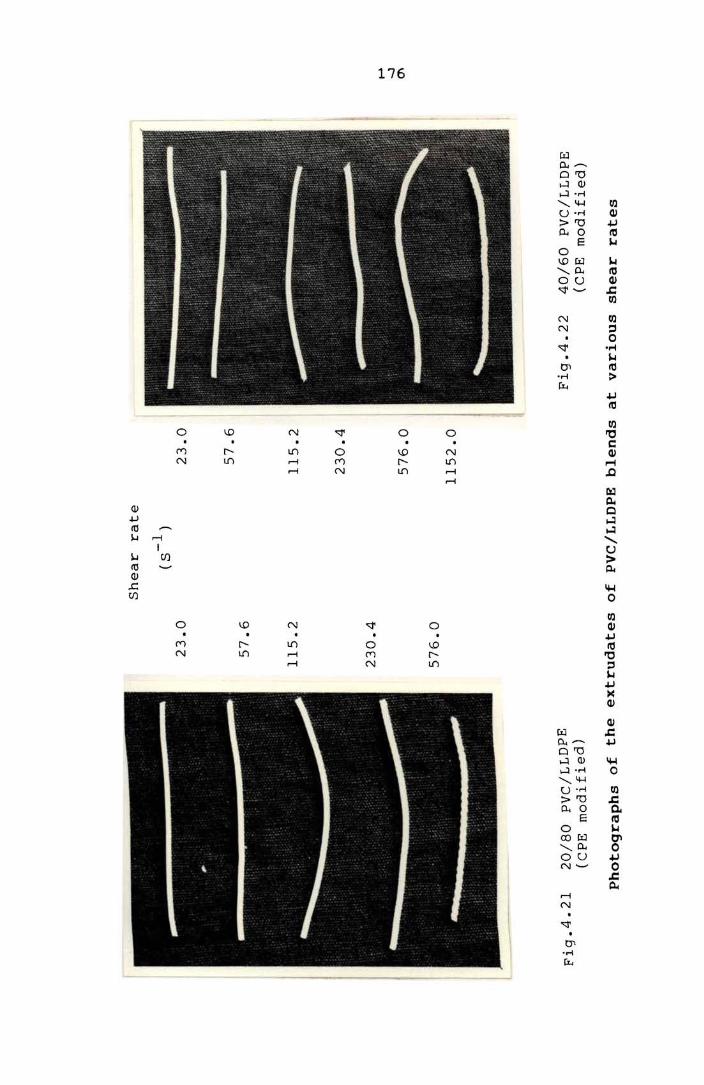
Fig
.4.
21
20
/80
P
VC
/LL
DP
E
(CP
E
mo
di
fied
) F
ig.4
.22
4
0/6
0
PV
C/L
LD
PE
(C
PE
mo
dif
ied
)
Ph
oto
gra
ph
s o
f t
he
ex
tru
da
tes
of
PVC
/LL
DPE
b
len
ds
at
va
rio
us
shea
r
rate
s

-1
Sh
ea
r
ra
te
(S
)
23.0
23.0
57
.6
57
.6
• --~
• •
• -~
• •
Fig
.4.2
3
LLD
PE
(un
mo
dif
ied
) F
ig.4
.2
4
LL
DPE
(C
PE
m
od
ifie
d)
Ph
oto
gr
ap
hs
of
the
extr
ud
ate
s o
f L
LD
PE
at
va
rio
us
sh
ea
r
ra
tes
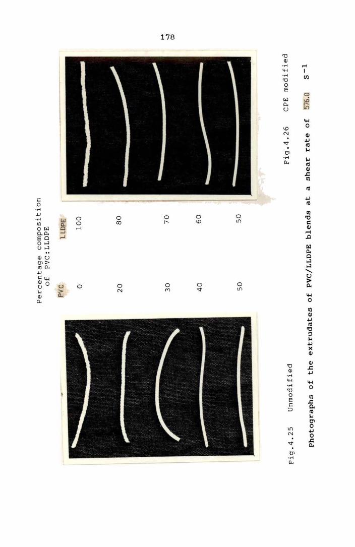
Fig
.4.2
5 U
nm
od
ifie
d
Percen
tag
e
co
mp
osi
tio
n
of
PV
C:
LL
DP
E
PV
C
lLll
PE
o 1
00
20
8
0
30
7
0
40
6
0
50
5
0
Fig
.4.2
6
CPE
m
od
ifie
d
Ph
oto
gra
ph
s o
f th
e
ex
tru
da
tes
of
PV
C/L
LD
PE
b
len
ds
at
a sh
ea
r
ra
te o
f 57
6.0
S
-1
... ..., (Xl

179
elastic nature of the melts of the PYC/LLDPE is reduced by
the addition of pvc. This behaviour is in conformity with
the die swell characteristics of PYC/LLDPE blends.
MODIFICATION OF PVC/LLDPE BLENDS BY CO-CROSSLINKThlG US:rn:; DCP
Crosslinking of polymers improves their
mechanical stability at high temperature, creep and
tensile properties. Polyolefines are sometimes modified
with organic peroxides to alter their processability and
mechanical . 29,30
propertles. It is known that the
effectiveness cf the chemical crosslinking of polyolefines
can be increased by the use of co-agents. Various radical
initiators, amines etc., can act as co-reactants/co-agents
h · h h h h . 1 . b h' 29 w lC en ance t e c emlca reactlon etween t e reSlns.
The use of such co-agents is of great importance in the
case of polymers containing tertiary carbon atoms in the
chain. The abili ty of organic peroxides to function as
crosslinking agent for PYC also has been described
. 30-33 earller. If two pOlymers which are incompatible can
be co-crosslinked I it may be possible to achieve better
properties and better technical performance. The
1 it era t ure conta ins i nforma t lon a bout the improvement in
physico-mechanical properties of immiscible polymer blerds

180
h h 1 ° kO 34,35 t roug co-cross ln lng. Nakamura et al.36
studied
the effect of partial co-crosslinkirg on the mechanical
properties of PVC/PE blend. In this study the effect ef
modifying PVC/LLDPE blends by dicumyl peroxide is
reported, since such modification is likely to introduce
some co-crosslinking in PVC/LLDfS blends, it may improve
the compatibility, mechanical behaviour, thermal
resistance, creep resistancE, ~olvent resistance etc., of
the blends.
Experimental
Polymer bleods were prepared on a Brabender
plasticorder. Mixing conditions were 160°C and 30 rpm.
LLDPE was added first, then PVC with its heat
stabiliser(s) and finally DCP was added. Three different
stabilisers viz., Tribasic lead sulphate (4 parts per 100
parts of PVC ie., 4phr), IrgastabA70 (4phr), ZnO
(4 phr)/MgO (4 phr)/stearic acid (3 phr) were used in this
study. Test samples were prepared by compression m~ulding
at l80°C for 3 minute~. The tensile propc:rti€E ef the
blends were determined on a Zwick univers2l testing
mschine using a cross head speed of 50 mm/min.

181
Results and Discussion
For determining the effect of co-crosslinking, the
higher molecular weight polymers (PVC-2 and LLDPE-I) were
used. Fig.4.27 shows the Brabender torque curves of the
30/70 PVC/LLDPE blend. A large increase in torque value
is obtained upon DCP addition. It shows that DCP
introduces some crosslinking in the matrix. When the
samples for tensile testing were prepared, mixing was done
at 160°C to prevent crosslinking during mixing permitting
it to occur during compression moulding done at 180°C.
Another observa t i on from the figure is t ha t there is a
pronounced increase in the band width of the torque curve
at the end of mixing in the case of DCP modified blends.
This may be due to the higher crosslink density at the end
of mixing.
It is well known that crosslinking changes the
stress-strain behaviour of the polymers. Fig.4.28 shows
the tensile stress-strain curves of an unmodified and DCP
modified 20/80 PVC/LLDPE blend containing different PVC
stabilisers. All the blends show some improvement in the
yield strength with modification by DCP which shows that
the matrix has become stronger by the crosslinking an:3 from
the better compatibility re2ulting from it.
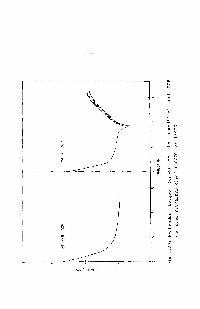
E
z '"
w
=>
o 0:: o I-
6
WIT
fIOU
T
OC
P
WIT
H
OC
P
\ \ \
2
2 4
6 8
2 4
G
8
TIM
E (
MIN
)
Fig
.4.2
7:
Bra
ben
der
torq
ue
cu
rves
of
the
un
mo
dif
ied
an
d
DC
P
mo
dif
ied
P
VC
/LL
DP
E
ble
nd
(3
0/7
0)
at
18
0°C
f-'
00
N

0 .~ .
cJ')
cJ')
I.J..I
0:
I-
cJ')
16
12 B~
/ //
UN
MO
DIF
IED
4~
1 T
BlS
2 IR
GA
ST
AB
3 Z
nO I
MgO
/ SA
100
200
300
2
3
I~
100
ST
RA
IN( ·
f.)
~
zoo
,r--3
7.
MO
DIF
IED
300
Fig
.4.2
8:
Str
ess-str
ain
cu
rves
of
an
u
nm
od
ifi,
..,d
an
d
DC
P m
od
ifie
d
PV
C/L
LD
PE
(2
0/8
0)
ble
nd
co
nta
inin
g
dif
feren
t sta
bil
isers
I-'
CP
w

184
Since organic peroxides are also likely to
introduce degradative reactions In the polymer, the
mechanical behaviour of the samples containing three
different PVC stabilisers is compared in Fig.4.28.
Eventhough TBLS is staining and shows maximum colour
development, it shows maximum strength. Irgastab A 70
(amino crotonate) being metal free shows least colour
development, but lower mechanical ~trength compared to
TBLS. 37 This is probably due to the plasticising action
of this liquid stabiliser. MgO/ZnO/stearic acid
stabilised mixture also develops colour. It shows the
lowest yield strength and maximum elongation at break.
This is likely to be due to a lower crosslink density in
the matrix resulting
stabiliser.
from a higher loading of the
The effect of various levels of DCP on the
tensile strength of PVC/LLDPE blends is shown In
Fig.4.29. The blend having 0.5 phr DCP does not show any
significant' improvement in tensile properties. The blend
which has 1.5 phr DCP exhibits m'uch better mechanical
properties, but colour development is very pronounced.
So an optimum concentration of DCP may be taken as 1 part
per 100 parts of PVC and LLDPE.

, I rI-!J Z
25-
w 10rc:: r-lfl
W -l Vi Z W r-
5
o 10
185
o DCP 15phr
DCP 10po,r
• DCP 05phr
UNMODIFIED
I
20 30 50 PVC CONTENT(°r.)
Fig.4.29: Tensile strength of PVC/LLDPE blend as a
function of composition--Effect of DCP
concentration

186
RADIATION MODIFICATION
When polymers are irradiated, chemical compounds
are created which ln turn lead to permanent changes in
certain properties. The absorption of radi~nt energy can
cause the breakdown of the chemical bonds. Breakage of
the bond gives rise to free radicals which crosslink with
other radicals. Consequences of the irradiation of
polymers are not only the formation of crosslinks but also
molecular breakdown due to breakage of the main chain. As
a result, irradiation can lead to improvement
(crosslinking) or degradation (breakdown) of the
. . 38,39 propertles of the materlal. The chemi cal s t ruct ure
of the polymer and the radiation conditions decide the
dominating reaction. The properties of both PVC and PE
can be modified by high energy radiation. 40 ,41 Since such
modifications are likely to introduce some co-crosslinking
in the PVC/PE blend, it may improve the compatibility and
other properties of the blend. Further, while chemical
crosslinking is known to affect crystallinity of the
matrix and hence may adversely affect the mechanical
behaviour, radiation crosslinking is found to affect
42 crystallinity only less severely.
187
Experimenlal
Polymer blends were prepared on the Brabender
plasticorder. M i x in g con d i t ion s we r e 160 ° Can d 30 rpm.
LLDPE was added first, then PVC with its heat stabiliser
and finally 1 phr DCP was added as accelerator. Test
samples were moulded at 160°C fer 3 minutes to minimise
DCP induced crosslinking.
subjected to gamma radiation
Then
of
such samples were
different dosages.
Tens i 1 e propert i es were det ermi ned on a Zwi ck un i ver sa 1
testing machine using a cross head speed of 50 mm/min.
Results and Discussion
done by
dosages.
Radiation modification of PVC/LLDPE blends wG\S
subjecting the blends to various radiation
Table 4.3 shows the variation of tensile
propert ies and colour development of the unmodified and
radiation modified blends of 30/70 PVC/LLDPE blends with
radiation dosage. As in the case of DCP modification,
higher dosages give rise to degradations leading to colour
development. An irradiation dcoage of about 3 Mrads is
found to be an optimum giving rise to some crosslinking in
the matrix without serious degradation. Fig.4.30 gives a

188
Table 4.3: Variation of 30/70 PVC/LLDPE blend properties
with radiation dosages
Property Unmodified 3 Mrad 6 Mrad 15 Mrad
Tensile strength 8.8 11.9 10.3 11.0 (Mpa)
Elongation ( % ) 248 315 250 107
Colour Colourless Colourless Light Reddish ydlow brown
comparison of chemical and radiation modification of
PVC/LLDPE blends. From the figure DCP modification is
seen to be more effective in improving the mechanical
properties in addition to being less expensive.
CHEMICAL MODIFICATION
Functionalisation or chemical modification of
the polymers is another common means of improving the
physical and mechanical properties of the blends.43
-45
The chemical modification of polymers continues to be an
active field of research as evidenced by the number of
recent publications on this topic. The compatibilisation
of incompatible polymer blends via chemical modification
involves, functionalisation of one polymer to chemically

c Cl. ::E ::r:' to Z W a: tIf)
25
15
w 10 -' Vi z W t-
5
, \
10
189
• UNMODIFlED
6 RAD1AT]ON MODIFIED
o CHEtv1JCALLY MODJFIED
20 30 50 PVC CONTENT (0/.)
Fig.4.30: Tensile strength of PVC/LLDPE blend as a
function of composition--Comparison of chemical~radiation modification

190
link with the molecules of another type of polymer. For
example, pp can be functionalised to chemically link with
NBR during melt .. 43 mlxlng. Good mechanical properties are
generally obtained from the linkages formed between the
molecules of the two polymers. The compatibility
enhancement ln polyolefine/styrene maleic anhydride via
polar interactions was recently reported by Simmons et
al. 46 In this study acrylic acid, maleic anhydride,
phenol i c res i nand P-pheny 1 ene d i ami ne a re used for the
chemical modification of PVC/LLDPE blends. Dicumyl
peroxide is used as a sensibilizing agent in the case of
acrylic acid and maleic anhydride. 4l
Experimental
PVC/LLDPE blends of various compositions (PVC
content varied from 0 to 50% of the total polymer weight)
were prepared on the Brabender plasticorder. The level of
modifiers and stabilisers used for a 20/80 PVC/LLDPE blend
is shown in Table 4.4 as an example.
FunctionalisaLion
a) Acrylic acid/maleic anhydride
PVC with its heat stabiliser (2.5 phr tribasic
lead sulphate) was melt mixed with LLDPE at a temperature

191
Table 4.4: Recipe for the 20/80 PVC/LLDPE blend
PVC and Stabiliser
PVC = 8 9 (20% of total polymer)
TBLS 0.2 9 (2.5 parts per 100 parts of PVC)
Po1yethylene
LLDPE = 32 9
Modifiers
a) Acrylic acid
DCP
b) Maleic anhydride
DCP
= 1·2 9 (3 parts per 100 parts of PVC and LLDPE (3phr))
0.08 9 (0.2 phr)
= 1·2 9 ( 3 phr)
= 0.08 9 (0.2 phr)
c) P-pheny1enediamine= 1·2 9 ( 3 phr)
d) Phenolic resin-l = 1.2 9 ( 3 phr)
snC1 2 0.16 9 (0.4 phr)
MgO = 0.003 9 (0.07 phr)
e) Phenolic resin-2 1·2 9 ( 3 phr)
snC12 = 0.16 9 (0.4 phr)
MgO = 0.003 9 (0.07 phr)

192
of 150°C and 30 rpm. After 2 minutes, Dep (0.2 phr) was
added as the free radic~~ precursor/ and then acrylic acid
or maleic anhydride (3 phr) was added. Mixing was
continued for another 3 minutes.
b) Phenolic resin modification
Mixing was done at a temperature of 180°C and
30 rpm. After melt mixing of PVC and LLDPE/ phenolic
resin was added along with Sne12
as the accelerator.
After 3 min. MgO was added to neutralise the free acid.
The total mixing time was 8 min.
c) P-phenylene diamine modification
The mixing conditions were 18Doe and 3D rpm.
P-phenylene diamine (3 phr) was added after the melt
mixing of PVC and LLDPE. The mixing was continued until
the torque reached a steady value.
The test samples were prepared by compression
moulding at 180°C for 3 min. in a laboratory hydraulic
press. Tensile properties were determined on a Zwick
universal testing machine using a cr-oss head speed of
50 mm/min.
193
Results and Discussion
Fig.4.31 shows the Brabender torque curves of
the unmodified and acrylic acid modified PVC/LLDPE (40/60)
blends at 180°C. A large increase in torque occurs with
the addition of acrylic acid along with DCP (0.2 phr).
The Increase in torque (viscosity) is probably due to
1) co-crosslinking of the polymers in presence of
carboxylic acid and/or 2) grafting of carboxylic acid on
to the polymer chains. Since DCP concentration was low,
the grafting of carboxylic acid is probably the dominating
. 47,49 reactIon. .
The mixing temperature seems to be very critical
for successful chemical modifications. When the mixer
temperature is ~ 180°C the torque curves of the acrylic
acid modified blends resemble those of the unmodi fied
blends without any significant increase in torque values
(Fig.4.32). Hence for preparing test pieces of the
modified blends, mixing was done at 150°C and then
compression moulding at 180°C for sufficient time for the
modifying action to take place.
The preferred site for the grafting IS possibly
the tertiary carbon atom of LLDPE and the carbon atom to
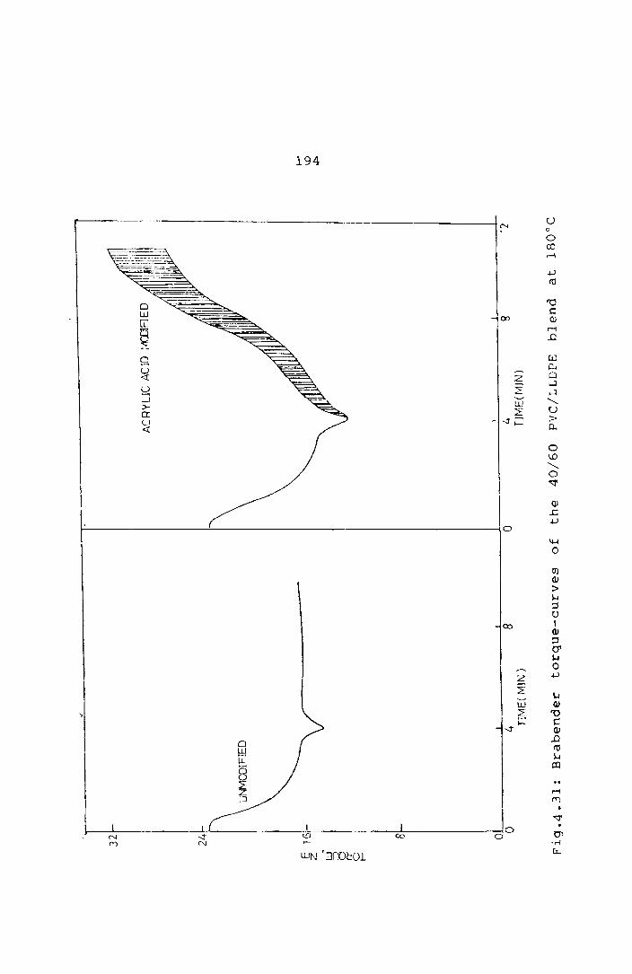
32 2!J
E
16
'z , L;
J a et
o t-
8
'UN
MO
DiF
1ED
I O~
4 8
o T
lME
( M
IN)
o 4 TIMEu,.,n~)
8 12
Fig
.4 .
31
: B
rab
en
der
torq
ue-c
urv
es
of
the
40
/60
P
VC
/L L
DPE
b
l en
d
at
18
00
C
I--' ~ ~

3J
, .... ~ :-
-
~ 1G
r
:~ I
§ I
o f-
I I Br o
\ !
0
15
0C
4 TJME(~~lN )
8
o I '"' Ti~.1~(M1N )
Fig
.4.3
2:
Bra
ben
der
torq
ue-c
urv
es
of
the
acry
lic
acid
m
od
ifie
d
30
/70
PV
C/L
LD
PE
b
len
d at
15
0°C
an
d
18
0°C
i-'
1.0
Vl

196
which the chlorine atom is attarhed In PVC. Grafting can
give rIse to strong interaction between the phases.
Another observation is that, with increase of PVC content,
there is a pronounced i ncrea se in the bandw i dt h 0 f the
torque curve at the end of mixing (Fig.4.33,. Similar
beha v i our wa s also observed whe n L LDPE a lone wa s cross-
linked with various concentrations of DCP. Hence it may
be concluded that the Increase in the bandwidth of the
curve is due to higher crosslink density and that PVC is
more susceptible to crosslinking and modification than
LLDPE.
The acrylic acid grafting on the polymer chains
was confirmed by IR spectra. IR spectra of the modi fied
blends (excess carboxyl ic acid free) were taken wi th a
Beckman Infrared spectrophotometer. Fig.4.34 shows the IR
spectra of unmodified, acrylic acid modified and acrylic
acid--DCP modified LLDPE. It shows that acrylic acid
grafting occurs only in the presence of DCP. The band at
1730 cm -1 shows the presence of )c=O groups. The IR
spectrum of 30/70 PVC/LLDPE blend also shows acrylic acid
grafting (Fig.4.35).
The variation of tensile strength with composi
tion for thE unmodified and carboxylic acid modified
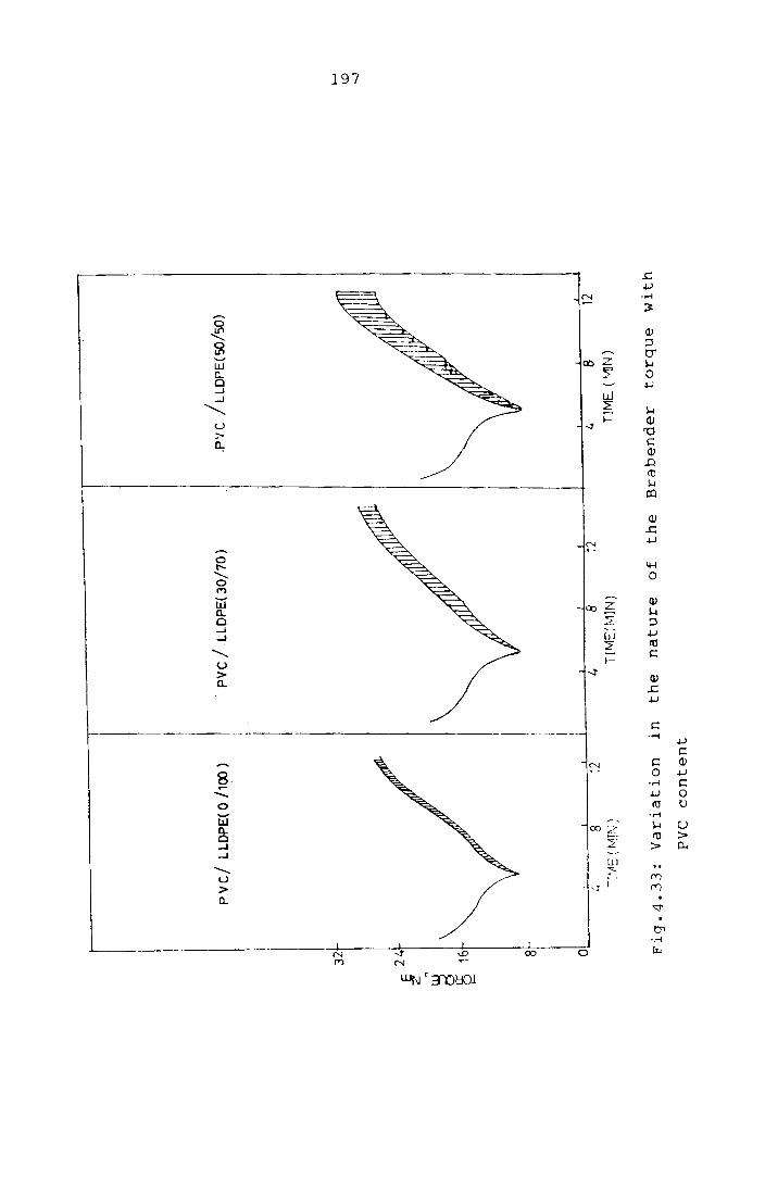
32
E 2
4
z ~ g 1
6 ~
8
I I I
pvc/
LLD
PE
(O /
10
0)
I .
, i : . I ,
. P
VC
/
LLD
PE
:( 3
0/7
0)
.P'J
C /
LL
DP
E( S
O/5
0)
01
I!
! I
I I!
I
~ g
12
4 8
12
L. 8
12
-:',
1E
(tvI
!\;
TIIv
1E:M
1N)
T1M
EU
v'!lN
)
Fig
.4.3
3:
Vari
ati
on
in
th
e
natu
re
of
the
Bra
ben
der
torq
ue
wit
h
PVC
co
nte
nt
f-'
\,0
...
J

GOI-\
.. --
LLO
PE

\- ----------
l ----'-~ 0
r---, 0
i ,-<)
'-------------iO _ 0
:r:: t' --- Cl- 'V
I -- I \V
.-~=--=--===.. ... -..,
/----- I l.-< I -....
!
I /
'7J I 0
\ ~f: E
i ~-
!
I
I 0-
"'--
\.~
\ g
"'-. .,'
I ...... '~----- u-- I
,
! ---- I I '<.'
~ ,.---------==-:=::-:> Is -,..., u
I /' ro
I ~ -, ",
! i r-
i 0 ------=-===-~-=.:> (1
t'
I r--
, ,'- .r---:
I '-- r-- i>-o
I~ .-i r-i
0 I"l
!~. >.
I \..J
U-l 0 :.j U
! 0_ i<: :1.1
0 -, (;~ ro
I .-l ~
I .-l
-:=?
.......... L!J ~
U ,- 0 'V
> I ~
CL I >- c
CJ i E r-i
\ ;0 ::l ..0 le, \..J In ..,.;
r'J W
I u 0-Q.I Cl 0.. ...:l
'-- :r: rJj ...:J
-----~ -u----- I I '--
----- 0 ..---------_._-----------:-..:..=:.::. 10 0:: >
// ju H c.. I~'; I
! ! l:", er!
l f le -<:;
I 0-'
-t; --'''-'--- ----- .. -------, I i-: -., C·} r.:..
(:)
(Civ ) :; )r~\tj J ):.'6 ~ J"1tL

200
PVC/LLDPE blends is sho\<:n in Fi9.4.36. Go:)d ir.:provement
in tensile strength is found to result fro~ the chemical
modifiration. ! i 9 .4 . 37 s how ~ the \- a r i c t i 0:1 i nth e y i e 1 d
stress. I t l sal so f 0 u ne" ;\ a tin C J: e <:; sin 9 t ~ e con c e n t !" a -
tions of acryJ ie acid/r.:aleic anhydrioE: or DCP does not
result 1n further in:prv\lE-rnent in properLies. Chemical
~odification lS found to vary the stress-s~!"ain beheviour
substantially (Fig.4.38).
Fig. 4 . 39 9 1. V est he e f f e c t 0 f ch en.i c .~d me Cl i f i ca
tions using phenolic resin and P-phen~lene diamine on the
tensile strength of PVC/LLDPE blends. The abili ty of
phenolic resin to improve the ultimate properties of PE or
pp ble:1d with NBR has previously bee") reported. Both
types of phenolic l-esins (high methylol type and resin
ccntain:ng hexamine) were used for the technological
compatibilisation. Even though these modi Eications result
in marginal improvements, it is not comparable with the
improvement obtained with carboxylation.
CARBOXYLIC ACID MODIFIED PVC/LLDPE BLEt~D AS fIN ADHESIVE
Earlier studies show that the intr.oduction of
some polar groups can increase the adt€~ive bond strEngth
of pclyolefines to various materials (~pecially metals.
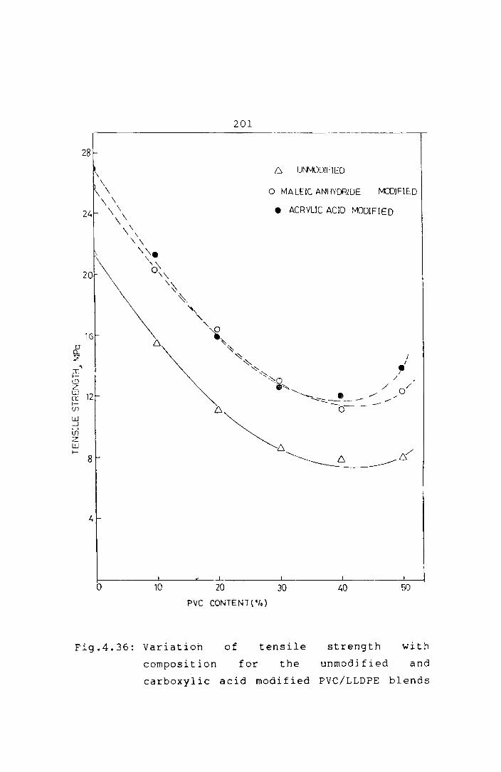
201 --------------------- .. -------... -.------~
28
UI\\'vXiU!I-Il::Q
o MALEIC ANINDRIDE tv(D1FIED
24 • ACRYLIC ACID rv'ODIFIED
\
20
1G
& 2:
'\ ~ f-<....') L. UJ
12 Cl: 1-(f)
W -.J
V) z: W f-
B
o 10 20 30 40 50
PVC CONTENT("Io)
Fig.4.36: variation of tensile strength with
composition for the unmodified and
carboxylic acid modified PVC/LLDPE blends

1 3
12
1 1 .
202
.. --.---. -- --_ .. _-_._----- .. _. ------.---------
MmF1ED rln) / (ACRYLIC A/
•
/ /e
------__ L-__ .- -. ---:::!-:' :----__ ---J.'::--____ ..."., __ . __ ---''--_
o 10 20 30 40 ~)O PVC CONTENT( 0'0)
Fig.4.37: Variation of yield stress ~ith composition
of PVC/LLDPE blends

24
18
a ~ If)
If) 12
w
0:
: !-
If)
,,- J~
11
'"
pvc
/ LL
DP
E( 01
100
)
/ /
./
MO
D1F
IED
/
/
/
/
/ /
/
/ / /
/
/ /
/ /U
NM
OO
FIE
D /
/ / I
r I I r i I I i f I ! 1
r ~I ! i/I :1/
/
.--'"
/'
./
./
PV
C /
LL
DP
E(
20
/80
)
t / / tv
()D1F
IED
/ / / /
/ /
/ /
/ /
/ /
/
UN
MO
DIF
IED
01
, ,
, r
, 1
' o
150
JX)
450
0 10
0 20
0 30
0 S
TR
AIN
(%)
ST
RA
IN(
"10)
Fig
.4.3
8:
Str
ess-s
train
cu
rves
of
LL
DPE
an
d
20
/80
P
VC
/LL
DP
E
ble
nd
I\J o w

d [!.
:L,14
~ 10~1 .-J
G 2 W !-
6
2
o 10
A.
o
•
20
204
P. PHFNYLE: £ DIA'<l!<::: MCfJiF1E D PHENOLIC RESH~ 2 M'X)IFlED
PHEr\j:U~ RESiN 1 MJJIFiEO
30
Fig.4.39: Variation of tensile
composition of PVC/LLDPE tlend~
wit.h

205
Ethylene copolymers with polar groups were found to have
such adhesive properties. The polarity of the groups on
the polymer chcin lS utilised to support adhesion to
. . 1 12 var10US mater1a s. 48 Hjertberg Et al. have studied the
effect of various functional groups on the adhesion
capability of polyolefine to metals. They found that
carboxylic acid is very effective in increasing the
adhesion between the po1yethylene and metal. In this
study acrylic acid and maleic anhydride modified PVC/LLDPE
blend, is investigated fur its adhesive properties with
metals.
Experimental
Thin metal sheets (steel and aluminium) were
cleaned wi t h emery paper and then degreased. Then the
sheet metal and the polymer were pressed together in a
laboratory hydraulic press at 180°C for 3 min at
120 kg/cm 2 Then the metal/polymer sample pressure. was
taken out of the hydraulic press, cooled to room
temperature and the peel resistance (adhesive bond
strength) of the joint was determined. The adhesive bond
s t reng ths between meta 1 a nd modi f i ed pol ymer bl ends were
assessed from the resistance to peeling of a 25 mm strip
polymer sample from the metal surface, angle of pE.eling
being 180 0 at 50 mm/min test speed.

206
Results and Discussion
PVC/LLDPE blends are found to show good adhesive
properties to metals such as steel and aluminium. The
bond strength is found to be much superior in the presence
of pvc. This result confirms our earlier observation that
chemical modification of the PVC/LLDPE blend is more
efficient than that of LLDPE alone. The peel strength of
the carboxylic acid modified LLDPE and its blend with pvc
is given in Table 4.5.
Table 4.5: variation of peel strength of the carboxylic
acid modified PVC/LLDPE blends with blend
composition
Percentage composition of PVC : LLDPE·
o 100
20 80
30 70
40 60
50 50
PEEL RESISTANCE (N/mm)
Acrylic acid treated Maleic anhydride treated
Steel Aluminhnn Steel Aluminium
8.90 6.62 5.24 3.48
9.82 8.25 5.86 4.47
15.34 10.81 6.26 4.71
12.00 10.12 5.50 4.41
11.68 7.37 3.51 2.82

207
The peel strength of the modified PVC/LLDPE
blends is found to improve steadily with PVC content but,
when the PVC content exceeds 30% of the total weight, the
strength of the polymer matrix IS not suffl~ient to
support the high bond strength. It is found that the
i nt roduct ion of pol ar funct 2 i.a 1 groups to PVC/LLDPE blend
increases adhesion and blend compatibility which ~kes them
suitable for sophisticated end uses In place of me e
expensive polymers.
The water and temperature resistance of the
adhesive bond is important when its practical utility is
considered. To assess the water resistance of the
adhesive bond the specimens were immersed in boiling
water. The resistance to boiling water IS shown in
Table 4.6.
The boiling water resistance of the adhesive
bond for acrylic acid
high but the modified
resistance even after
not very modified LLDPE alone IS
PVC!LLDPE blends show very good
in boiling 50 hrs of immersion
water. This observation is also In conformity v.Jith the
earlier observation that the presence of pvc increases the

------------- ---------31cr:G Cf.:~1pC..=iLj:::;;;
r't: r- C E:;~ tag e
?vr : U nr-s
c leO
')" ~ , 80
~!:J le)
40 60
50 50
I Lit i (-; 1 ;;- Ej e 1 E~:: €!~g t h
6.62
8.25
lCi.80
10.10
7.37
?f:€ol [:rength (N/n~r.") cf:€', :. :-, :. '( E. ~ I. irnrne r ~: l \.. ~-;
5.62
:-' • -:<,1
4.62
4.28
a ,3 h e s i \' e b 0 n d s t r en g t h • Ti~e chemical resi~tance of the
acrylic acid mrdified bl~nd~ was determined by keeping it
in the respecti'.'€ chemicals at a;:-,oiE:-nt tenlpt'Lature for O!1€
The perCt'nt agE' i nor-case j n 'weight ef the acrylic
EciC m0~ific6 blEn6~ in oil, tcl1J( ne -. r ,., --. - ,.-, t r - t c" U"· --) C _'; . '- t - 1._ a e l .-:: - \ ~ 3

209
Table 4.7: Chemical resistance of the acrylic acid
modified PVC/LLDPE blends
Percentage PERCENTAGE INCREASE IN WEIGHT
compos i- At room temp. for tion of
7 days At 70°C for 24 hrs
pvc : LLDPE Oil Toluene Con.HN03 Oil H2O
0 .. 100 5.0 21.4 3.3 30.6 1.4
20 80 2.7 28.6 2.6 30.0 1.6
30 70 2.4 25.6 2.4 17.1 2.1
40 60 1.0 23.8 3.2 14.3 1.6
50 50 1.3 25.0 3.8 13.1 2.1
The blends are found to have good chemical
resistance in these media. The blends also possess good
dimensional stability in hot oil and hot water.
210
REFERENCES
1. C.Sadrmohaghegh, G.Scott and Setudeh, Polym. Plast.
Technol. Eng. 24 (2 & 3) 149 (1985)
2. Raija Mikkonen and Antti. Savolainen, J. Appl. Polym.
Sci. 39 1709 (1990).
3. T.Palotas, J.Somfalvi and K.KupL Int. Polym. Sci.
Technol. 17 (2) T/19 (1990).
4. A.Ghaffar and G.Scott, Eur. Polym. J. 14 631 (1978).
5. A.Ghaffar, C.Sadrmohaghegh and G.Scott, Eur. Polym. J.
17 941 (1981).
6. L.K.Sanghi, A.S.Bhattacharyya, B.Mukherjee, A.K.Sen,
P.P.De, Anil K.Bhowmik, Proc. Int. Wire Cable Symp. 38
306 (1989).
7. Ralph H.Thomas and S.Thomas, Polymer News, 8 (6) 169
(1982).
8. D.R.Paul and S.Newman (Eds), Polymer Blends, Academic
Press, 1, Chapter 6 (1978).

211
9. J.A.Manson and L.H.Sperling, Polymer Blends and
Composites, Plenum Press (1976).
10. O.Olabisi, L.M.Robeson and M.T.Shaw, Polymer-Polymer
Miscibility, Academic Press, Chapter 5 (1979).
11. L. A . Ut r a c k i, Po 1 ym • P 1 a st. Te c h n 0 1. En g . 22 ( 1) 2 7
(1984).
12. Daniele Romanini, Polym. Plast. Technol. Eng. 19 (2)
201 (1982).
13. M.M.Coleman, C.J.Serman, D.E.Bhagwager and
D.C.Panita, Polymer 31 (7) 1187 (1990).
14. M.Xanthos, Po1ym. Eng. Sci. 28 (21) 1392 (1988).
15. P.Bataille, C.Jelicouer and H.P.Schreiber, Society of
Plastic Engineers Antec. 30th Annual Technical
Conference, New York, Technical papers, p.475,
(1980).
16. C.E.Locke and D.R.Paul, J. Appl. Polym. ScL 17 2597
(1973).

212
17. H.Munstedt, J. Macromol. Sci.-Phys. B14 (2) 195
(1977).
18. J.Francis, K.E.George and D.J.Francis, Kautschuk
Gummi Kunststoffe 43 (3) 193 (1990).
19. C.H.Hoffmann, Polym. P1ast. Technol. Eng. 20 (2) 197
(1983) •
20. J.T.Lutz, Polym. Plast. Technol. Eng. 21 (2) 99
(1983).
21. C.L.Sieglaff, Polym. Eng. Sci. 9 81 (1969).
22. U.K.Saroop, K.K.Sharma and K.K.Jain, J. Appl. Polym.
Sci. 38 1421 (1989).
23. B.Rabinowitsch, Z. Physik. Chem. A145 1 (1929).
24. J.A.Brydson, Flow Properties of Polymer Melts, Second
edition, George Godwin, London, Chapter 3 (1981).
25. C.D.Han, Multiphase Flow in Polymer Processing,
Academic Press, New York (1981).

213
26. L.A.Utracki and M.R.Kamal, Po1yrn. Eng. Sci. 22 96
(1982).
27. K.T.Varughese, P.P.De and S.K.Sanyal, J • Vinyl
Technol, 10 (4) 166 (1988).
28. E.B.Bag1ey, J. AppJ. Phys. 28 557 (1957).
29. D.W.Woods, W.K.Busfield and I.M.Ward, Plast. Rubb.
Process. App1. 9 (3) 155 (1988).
30. J.de Boer an1 A.J.Pennings, Polymer 23 (13) 1944
(1982).
31. L.Ka1afski and V.M.Zhiznevskii, Int. Po1ym. Sci.
Techno1. 14 (5) T/73 (1987).
32. L.L.Valdiserri and G.V.Reed, Rubber World 170 (5) 40
(1974).
33. Vratislav Duchacek and Antonin Kuta, J. Appl. Polym.
Sci. 27 1549 (1982).
34. Y.Nakamura, K.Mori and R.Takesawa, Int. Polyrn. Sci.
Techno1. 7 (7) T/9 (1980).

214
35. Y.Nakamura, K.Mori and R.Takesawa and M.Saito, Int.
Polym. Sci. Techno1. 7 (2) T/89 (1980).
36. Nakamura, Yoshoro, Watanabe, Akira, Mori, Kuinoi,
Tamura Kosaku, Miyazaki Hitosi, J. Polym. Sci. 25 (3)
127 (1987).
37. w.v.Titow, PVC Technology, Elsevier Applied Science
Publishers, fourth edition, Chapter 10, p.347 (1984).
38. G.S.Ivchenko, T.K.Shaposhnikova, S.N.Ll'n,
B.M.Vanyushkin and V.G.Konkov 8 (7) T/78 (1981).
39. Z.S.Egorova, V.I.Dakin, V.L.Karpov and R.S.Barshtein,
Int. Po1ym. Sci. Techno1. 7 (9) T/3 (1980).
40. W.Birkigt, R.Mul1er and K.Posse1t, Int. Polym. ScL
Techno1. 15 (5) T/12 (1988).
41. M. Ma teev and M. Ni kol ova, P last. Rubb. Process. Appl.
15 241 (1990).
42. L.M.Kulkarni and R.Mashelkar, Polymer 22 1665 (1981).

215
43. A.Y.Coran and R.Pate1, Rubb. ChCil. Technol. 56 (5)
1045 (1983).
44. N.e.Liu, W.T.Baker and K.E.Russel1, J. Appl. Po1ym.
Sci. 41 9 (1990).
45. D.N.Schulz and S.R.Turner, Rubb. Chem. Techno1. 55
(3) 809 (1982).
46. A.Simmons, W.E.Baker, Po1ym. Cornrnur.. 31 (1) 2 (1990).
47. L.P.Kru1 , Yu I.Matusevich and A.M.Nikiforov P1ast
MassYI 7 77 (1990).
48. T.Hjertberg and J .E.Lakso, J. Appl. Po1ym. Sci. 37
1287 (1989).
49. Jayarnma Francis and K.E.George, J. E1ast. and Plast.
(in press).
Chapter 5
SUMMARY AND CONCLUSIONS

SUMMARY AND CONCLUSIONS
Several elastomers were modified with PVC, the
most notable among these being polychloroprene rubber
(CR). Modification of CR with PVC was found to improve
oil, petrol, ozone and fire resistance of CR. However,
the mechanical properties of PVC/CR blends were far below
the average properties of CR and PVC. Hytrel, EVA and NBR
were found to be effective compatibilisers for improving
the mechanical behaviour of PVC/CR blends ~,6 The modified
pvC/eR blends can replace CR in critical applications
requiring superior chemical resistance, flame resistance
and ageing resistance.
In order to study the mechanism of modification
by Hytrel, EVA and NBR, the melt rheological properties of
these modifiers and their blends with PVC were evaluated.
It was found that all the three modifiers reduce the
viscosity and non-Newtonian behaviour of PVC showing that
these modifiers make the flow of PVC easier and more
uniform. The flow curves (shear stress vs. shear rate
curves) of PVC/Hytrel, PVC/EVA and PVC/NBR were found to
display a uniform pattern. Each of them could be
represented by two straight lines, each straight line
216

217
representing a particular flow behaviour. The initial
st ra i ght 1 i ne represents largely the behaviour of the
mod if i er a lone when the PVC pa rt i c les rema i n un fused to
any great extent and the second straight line represents
the true flow behaviour of the melts of the blends when
the PVC is mostly in the molten state. There is a
critical shear rate, which is a function of the blend
composition and the temperature, at which transition from
the first flow behaviour to the second one occurs. Hence
the modifying action of Hytrel, EVA or NBR on PVC blends
was concluded to be due to the following: 2
1. Plasticising action on Pvc which makes fusion of PVC
particles faster and/or at a lower temperature.
2. Making the flow of pvc smoother and easier, enabling
more efficient blending with the other constituent.
3. Lowering of the critical shear rate for a particular
composition and temperature at which fusion of pvc
particles occurs.
The second part of the study on PVC/LLDPE blends
was motivated by the rising volume of polymeric materials

218
to be found in industrial and muncipal wastes. PVC and
polyethylene constitute about 50 per cent of all polymer
wast es and hence recyc 1 i ng PVC/PE bl ends wi 11 give some
guidelines as to how the ever increasing problem of
pollution by non-biodegradable polymers can be mitigated.
Chlorinated polyethylene was found to be~very useful
additive for PVC/LLDPE mixtures for improving both the
~echanical and processing properties of the blends. 3 ,S
Co-crosslinking of the PVC/LLDPE blends was found
to be another promising method for improving the physical
and mechanical properties. Modification by chemical means
(by using an organic peroxide) and by irradiation (by
using gamma radiation) was found to improve the strength
and stiffness of the matrix since the dominating reaction
in both cases was that of co-crosslinking. It was also
observed that the degradations in the blends during the
course of such crosslinking can be minimised by uSlng
certain stabilisers which thus impart good colour
flexibility to the blends.
Functionalisation or chemical modification of
polymers was found to be another way of improving the
mechanical properties of PVC/LLDPE blends.4
Modification

219
by acrylic acid and maleic anhydride in presence of
dicumyl peroxide
compatibility of
was found to be useful in improving the
the blends. The improvement was found
to be mainly due to the grafting of carboxylic acid to
the polymer chains and the grafting was found to be more
effective in PVC/LLDPE blends than in pure LLDPE.
The grafting of acrylic acid or maleic anhydride
to the polymers was also found to improve their adhesion
with various materials. Acrylic acid and maleic
anhydr ide modi fied PVC/LLDPE blends displayed very good
bonding with metals like aluminium and steel. The bond
was found to be much stronger in presence of pvc compared
to LLDPE alone.

220
REFERENCES
1. J.Francis, K.E.George and D.J.Francis, Kautschuk Gummi
Kunststoffe, 43 (3) 193 (1990).
2. Jayamma Francis and K.E.George, J. Polym. Eng. (in
pres.'3) •
3. Jay a mm a F ran c i san d K. E • G eo r 9 e, J. El a st. and P 1 as t •
( in press).
4. Jayamma Francis and K.E.George, Eur. Polym. J. (in
press).
5. Jayamma Francis and K.E.George, National Conference on
I Advances in Polymer Technology I, Conference papers,
p.203 (1991).
6. Jayamma Francis, Proceedings of the 77th Indian
Science Congress, Part 111 (Abstracts), p.47 (1990).

- c;, 5130 --221
LIST OF PUBLICATIONS FROM THIS WORK
1. Modification of Elastomers with poly(vinyl chloride),
Kautschuk Gummi Kunststoffe, 43 (3) 193 (1990).
2. Melt rheology of PVC blends, Journal of Polymer
Engineering (in press).
3. Studies on PVC/LLDPE blends, Journal of Elastomers and
Plastics (in press).
4. Chemical modification of poly(vinyl chloride) with
linear low density polyethylene, European Polymer
Journal (in press).
5. Chlorinated polyethylene as a compatibiliser for
poly(viny1 chloride)/polyethylene blend, presented at
the National Conference on 'Advances in Polymer
Technology', Cochin 1991.
6. Studies on PVC/Elastomer blends, presented at the 77th
Indian Science Congress--1990, Cochin (This paper won
the Young Scientist's Award).