
Student Course Book- Automation
1168
Automation Coll ege Experion PKS: Fundamentals - Control Execution Environment Controller & ACE Implementation EXP-2001 R400 Student Guide Rev 05.0 04/2012 Book 1 of 1
-
Upload
sourabh-arora -
Category
Documents
-
view
245 -
download
0
Transcript of Student Course Book- Automation

8/9/2019 Student Course Book- Automation
http://slidepdf.com/reader/full/student-course-book-automation 1/1165
Automation College
Experion PKS:Fundamentals - Control Execution
Environment Controller & ACEImplementation
EXP-2001 R400 Student GuideRev 05.0 04/2012
Book 1 of 1

8/9/2019 Student Course Book- Automation
http://slidepdf.com/reader/full/student-course-book-automation 2/1165
Notices
While this information is presented in good faith and believed to be accurate, Honeywell assumesno responsibility for any errors that may appear in this courseware. The courseware is presentedon an “as-is” basis. Honeywell disclaims the implied warranties of merchantability and fitness for aparticular purpose, and makes no express warranties except as may be stated in its written
agreement with and for its customer.
In no event is Honeywell liable to anyone for any indirect, special or consequential damages evenif Honeywell is informed of the possibility of these damages. The information and specifications inthis courseware are subject to change without notice.
No part of this courseware may be reproduced or transmitted in any form or by any means. It isintended for the use of the original purchaser only. Copying, duplicating, selling or otherwisedistributing the courseware is a violation of law. The materials and workbooks comprising thecourseware may not, in whole or part, be copied, photocopied, reproduced, translated or reducedto any electronic medium or machine-readable form without prior consent in writing fromHoneywell.
This courseware is the confidential and proprietary information of Honeywell. The courseware mayonly be used by the person who attended the Honeywell class. The courseware may only be usedin conjunction with a Honeywell system at the company that paid for the class. Only Honeywellmay use the courseware for training purposes.
This class has special equipment configurations that are appropriate only for training and shouldnot be used for any other purpose.
Experion, Da Vinci, IntelliMap, MXOpen, MXProLine, TotalPlant, PlantScape, TDC 3000,Uniformance, and Universal Control Network are registered trademarks of Honeywell International.
These commodities, technology or software were exported from the United States in accordancewith the Export Administration Regulations. Division contrary to U.S. law prohibited.
Copyright © 2012 Honeywell Inc.
Honeywell International, Inc. Automation College
Global Learning Services

8/9/2019 Student Course Book- Automation
http://slidepdf.com/reader/full/student-course-book-automation 3/1165
Program Objectives
Honeywell Confidential and Proprietary Page: 1 of 3 04/04/12
EXP2001R400 - EPKS CEE R400
Tab Lesson Objectives1 Orientation and Course Introduction
Course Introduction2 C200/C200E Controller Architecture
Describe the C200/C200E Controller ArchitectureDescribe the C200/C200E Controller Racks andRedundancyDescribe the C200/C200E I/O Modules
3 C300 Controller Architecture - Part 1 of 2 Describe the Main Features of the Series C SystemDescribe the Architecture of Series C SystemDescribe Series C Input-Output Modules andOptionsDescribe the IO Topology Rules for the Series C
SystemVerify Series C Hardware Connections
4 Control Builder Introduction Describe the Functionality of Control BuilderUse Compare Parameters OptionsUse Control Builder SearchDescribe How to Locate CB Concepts in KBOpen and Operate Control Builder
5 C200/C200E Hardware Configuration Concepts Describe the Configuration of C200/C200EHardware and I/O
6 C300 Hardware Configuration Concepts
Describe C300 and Series C I/O Configuration7 Control Builder Import / Export Procedure Describe the Import/Export Procedure in ControlBuilder
8 Controller Hardware Configuration Instructions for: Configure Controller HardwareConfigure C200E Controller and Series A IOM inSIM-C200EImport the Remaining Series A IO Modules into theSCEConfigure C300 Controller and Series C IOM inSIM-C300Import the Remaining Series C IO in to SIM-C300
9 C300 Controller Architecture - Part 2 of 2 Describe Fiber Optic Extender and Its ConnectionRulesDescribe the Control Firewall Connections in theSeries C SystemDefine a Typical Series C Configuration
10 Performance Calculations and Monitoring Describe Performance Calculations
11 Process Simulation for Lab Exercise

8/9/2019 Student Course Book- Automation
http://slidepdf.com/reader/full/student-course-book-automation 4/1165
Program Objectives
Honeywell Confidential and Proprietary Page: 2 of 3 04/04/12
Identify the Debutanizer Lab Sequence12 EXCEL Simulation
Describe the EXCEL Simulation Used for Labs13 Data Acquisition Control Module
Describe the Procedure to Build Control ModulesInstructions for: Data Acquisition Control ModuleConfigure Series A IO ChannelConfigure Series C IO ChannelConfigure the Data Acquisition Control Module
14 Productivity Tools in Control Builder Describe Bulk Build FunctionalityDescribe Bulk Edit Parameters FunctionalityDescribe the Block Name References in CM andSCMExport/Import a Control Module
15 ERDB Administration and Other Tools Describe ERDB Administration
16 Checkpoints Describe Checkpoint Settings in Control BuilderPerform Checkpoint SavePerform Checkpoint Restore
17 PID Control Module Describe PV Tracking and InitializationFundamentalsConfigure a PID Control ModuleCalculate Performance Statistics of theConfiguration Performed (C200 & C300)
18 PID with Split Range Control Module Configure a PID Control Module with Split RangeOutputs
19 Cascade PID Control Module Configure a Cascade PID Control Module
20 Cascade PID with Two Secondaries Configure a Cascade PID CM with TwoSecondaries
21 Output Reversal and Red Tag Indication Describe Output Reversal and Red Tag IndicationOptionsConfigure a Control Loop for OP ReversalIndicationsConfigure a Control Loop for Red Tag Indication
22 Device Control Module
Describe Templates and the Substitute Name ListConfigure a Device Control Module - with LogicConfigure a Device Control Module - with Interlock
23 Math and Auxiliary Function Blocks Describe Auxiliary Function BlocksDescribe MATH Function BlocksUse Rolling Average Function BlockUse Counter Function Block
24 Database Search

8/9/2019 Student Course Book- Automation
http://slidepdf.com/reader/full/student-course-book-automation 5/1165
Program Objectives
Honeywell Confidential and Proprietary Page: 3 of 3 04/04/12
Describe Search FunctionalityPerform Parameter SearchPerform Where Used Search
25 Sequential Control Module - Concepts and Use Describe the Configuration of SCMsConfigure a Sequential Control Module
26 SCMs - Programming Techniques, Operation Identify SCM Programming TechniquesExplain the Operation of SCMs
27 Sequential Control Module - Lab Add Function Blocks for SCM Program ControlSpecify SCM Recipe Values and Invoke TransitionConfigure an SCM Abort SequenceUse a Step to Start Another SCMUse Recipe Values to Set Minimum FlowInterface an SCM with a Graphic Textbox
28 Interactive Instructions
Describe Interactive InstructionsConfigure Interactive Instructions
29 SCM Abnormal Handlers Configure an SCM Abort HandlerConfigure an SCM Interrupt HandlerConfigure an SCM Check Handler
30 Final Project Complete the Final Project - 20
31 PMIO Identify PMIO HardwareDescribe the C200/C200E Hardware Interface tothe PMIO
Describe the I/O Card FileDescribe How to Configure PMIO HardwareDescribe How to Configure PMIO Channel Blocksin CMsDescribe PMIO Configuration in a C300 SystemConfigure an I/O Link Module (IOLIM) for C200EConfigure Digital, Analog and Hart IOPs
Assign, Load, and Activate PMIO for C200E Assign, Load, and Activate PMIO for C300Configure a Continuous Control Strategy withPMIOLoad, Activate, and Operate CMs with PMIO
32 Appendix Describe Types of PID Control BlocksDescribe Device Control BlocksDescribe the HPM Functions Duplicated in CEEDescribe Power Generation Function BlocksDescribe the HART Functionality in C200/C200EOperationsControl Module ReferenceGuide to Debutanizer Model for C200E/C300 Labs

8/9/2019 Student Course Book- Automation
http://slidepdf.com/reader/full/student-course-book-automation 6/1165

8/9/2019 Student Course Book- Automation
http://slidepdf.com/reader/full/student-course-book-automation 7/1165
1
1
Honeywell ConfidentialCopyright © 2012 Honeywell International Inc.
4/13/2012
Course Introduction
Orientation and Course Introduction Course IntroductionOrientation and Course Introduction Course Introduction
Honeywell
Honeywell ConfidentialCopyright © 2012 Honeywell International Inc.
4/13/20122
Topics
• Introduction to the course
• Navigating the self-paced computer-based lessons
Orientation and Course Introduction Course Introduction

8/9/2019 Student Course Book- Automation
http://slidepdf.com/reader/full/student-course-book-automation 8/1165
2
Honeywell
Honeywell ConfidentialCopyright © 2012 Honeywell International Inc.
4/13/20123
Purpose of This Course
• Experion PKS Control ExecutionEnvironment C200, C200E, C300and ACE course will provide youwith the ability to:
– Plan the C200, C200E and C300controller
– Configure C200, C200E and C300hardware, control modules andsequential control modules
– Build control strategies on the C200,C200E, C300 and ACE
ControlNet
SafetyManager
Human InterfaceConsole Operations
RT
PM I/O
LAN
Fault Tolerant Ethernet
ProcessServer
ACE C300
ESV-LCNConnected
TPS, TDC2000, TDC3000
NIM
C200/ C200E
Orientation and Course Introduction Course Introduction
Honeywell
Honeywell ConfidentialCopyright © 2012 Honeywell International Inc.
4/13/20124
Who Should Attend
• Experion System implementers who are responsible for designing andconfiguring the system:
– System engineers or application engineers who configure, add to or changethe C200, C200E, C300 or ACE controller configuration
– Maintenance engineers or technicians who add new control loops ortroubleshoot existing loops
– Others, whose job functions include performing these tasks
Orientation and Course Introduction Course Introduction

8/9/2019 Student Course Book- Automation
http://slidepdf.com/reader/full/student-course-book-automation 9/1165
3
Honeywell
Honeywell ConfidentialCopyright © 2012 Honeywell International Inc.
4/13/20125
What You Will Learn
• In this course, you will learn how to:
– Recognize the role of the major Experion PKS hardware and softwarecomponents and learn how data flows through the C200,C200E and C300controller
– Configure control modules that incorporate data acquisition, regulatorycontrol and logic
– Configure sequential control modules (SCMs) used to control processsequences such as startup, shutdown and batch operations
– Create parallel steps in an SCM for parallel branching
– Configure interactive instruction that allows a seamless combination ofoperator-guided manual intervention and automatic control in SCMs
– Configure additional I/O functionality for the PMIO
– Troubleshoot typical errors in configuration
Orientation and Course Introduction Course Introduction
Honeywell
Honeywell ConfidentialCopyright © 2012 Honeywell International Inc.
4/13/20126
Course Organization
• The Experion PKS ControlExecution Environment C200,C200E, C300 and ACE course isdivided into two sections:
1. The basic concepts and strategiesneeded, to develop guidelines foreffective and consistent systemplanning
• Self-paced computer-basedlessons or instructor-deliveredworkshops
2. A hands-on workshop in which youwill build and configure the ExperionPKS C200, C200E and C300controller
• Hands-on lab exercises withstep-by-step instructions
• Assessments to reinforceconcepts learned
ControlNet
SafetyManager
RT
PM I/O
LANProcess
Server ACE C300
Fault Tolerant Ethernet
TPS, TDC2000,TDC3000
NIM
ESV-LCNConnected
Human InterfaceConsole Operations
C200/C200E
Orientation and Course Introduction Course Introduction

8/9/2019 Student Course Book- Automation
http://slidepdf.com/reader/full/student-course-book-automation 10/1165
4
Honeywell
Honeywell ConfidentialCopyright © 2012 Honeywell International Inc.
4/13/20127
Topics
• Introduction to the course
• Navigating the self-paced computer-based lessons
Orientation and Course Introduction Course Introduction
Honeywell
Honeywell ConfidentialCopyright © 2012 Honeywell International Inc.
4/13/20128
Lesson Window
Navigation bar
Orientation and Course Introduction Course Introduction
8/9/2019 Student Course Book- Automation
http://slidepdf.com/reader/full/student-course-book-automation 11/1165
5
Honeywell
Honeywell ConfidentialCopyright © 2012 Honeywell International Inc.
4/13/20129
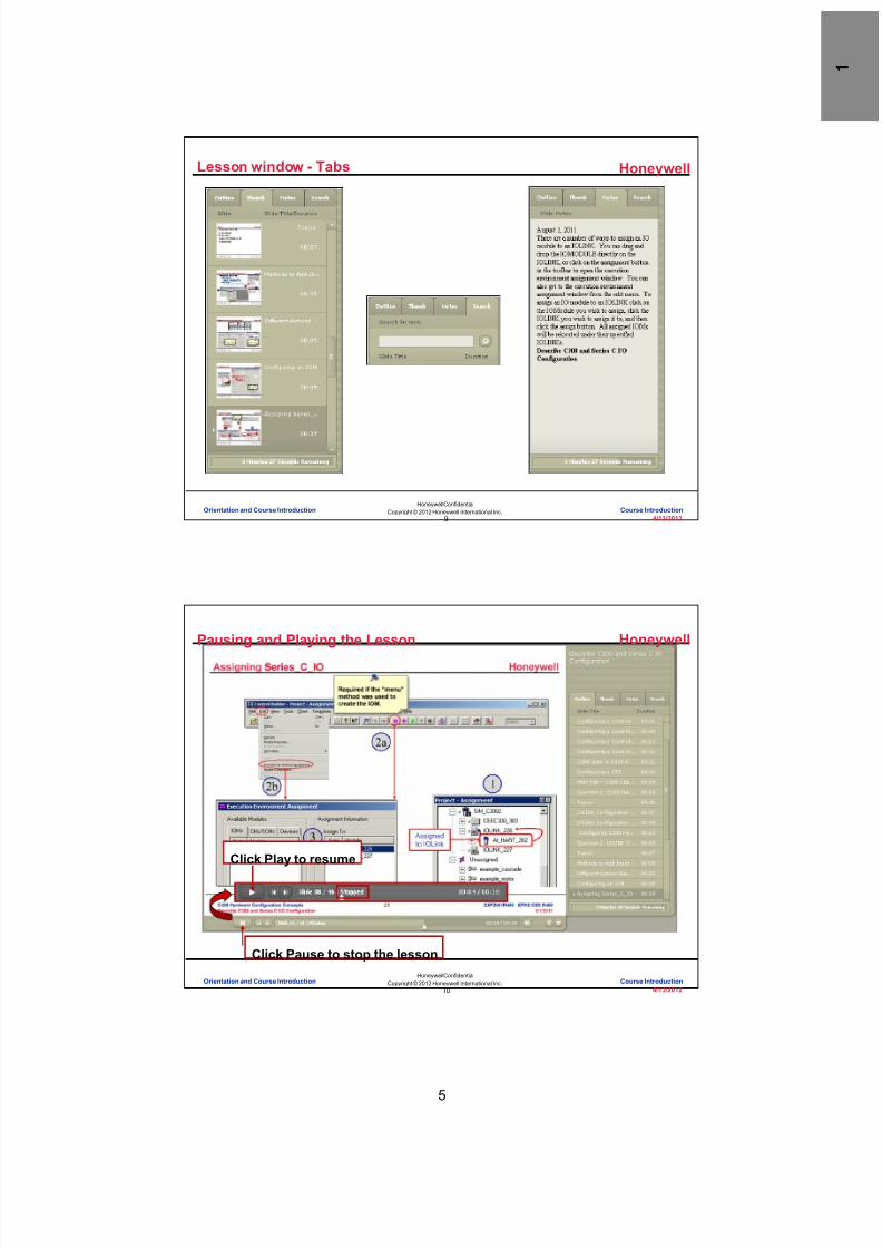
Lesson window - Tabs
Orientation and Course Introduction Course Introduction
Honeywell
Honeywell ConfidentialCopyright © 2012 Honeywell International Inc.
4/13/201210
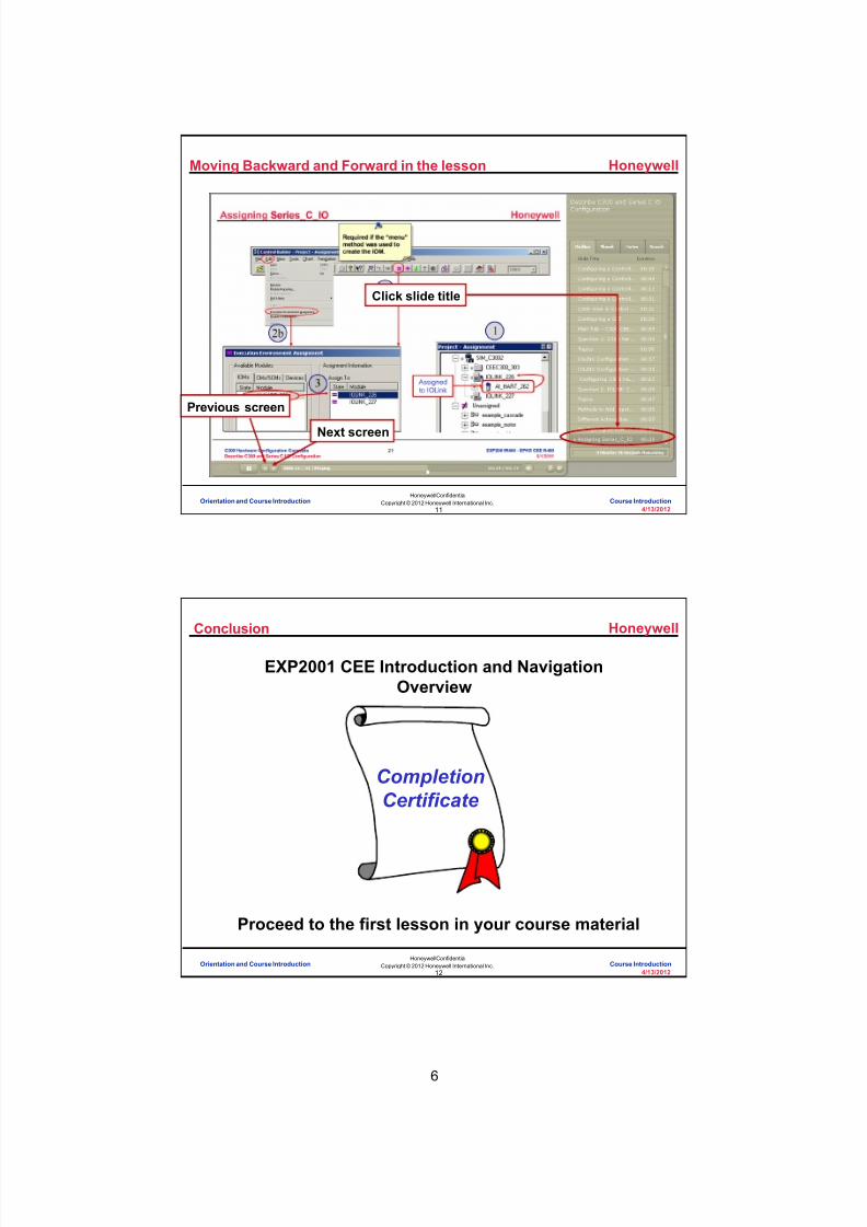
Pausing and Playing the Lesson
Click Pause to stop the lesson
Click Play to resume
Orientation and Course Introduction Course Introduction
8/9/2019 Student Course Book- Automation
http://slidepdf.com/reader/full/student-course-book-automation 12/1165
6
Honeywell
Honeywell ConfidentialCopyright © 2012 Honeywell International Inc.
4/13/201211
Moving Backward and Forward in the lesson
Previous screen
Next screen
Click slide title
Orientation and Course Introduction Course Introduction
Honeywell
Honeywell ConfidentialCopyright © 2012 Honeywell International Inc.
4/13/201212
Conclusion
CompletionCertificate
EXP2001 CEE Introduction and NavigationOverview
Proceed to the first lesson in your course material
Orientation and Course Introduction Course Introduction

8/9/2019 Student Course Book- Automation
http://slidepdf.com/reader/full/student-course-book-automation 13/1165
1
1
Honeywell ConfidentialCopyright © 2012 Honeywell International Inc.
4/13/2012
Describe the C200/C200E ControllerArchitecture
C200/C200E Controller Architecture Describe the C200/C200E Controller ArchitectureC200/C200E Controller Architecture Describe the C200/C200E Controller Architecture
Honeywell
Honeywell ConfidentialCopyright © 2012 Honeywell International Inc.
4/13/20122
• This lesson introduces you to the Experion PKS C200 and C200Econtroller architecture.
• At the conclusion of this lesson,you will be able to:
– Identify the high-levelcomponents and connections
– Explain the basic purposeof the components andconnections
– Identify C200 and C200E
Introduction
RT
RackI/O
Series A
PM
I/O
ExperionServer
ACE
Fiber OpticIsolation
Fiber OpticIsolation
ProcessControllers
Rail I/OSeries A
GI/IS Rail I/OSeries H
I/O OptionsControlNet
FTE
C300
C200/C200E Controller Architecture Describe the C200/C200E Controller Architecture

8/9/2019 Student Course Book- Automation
http://slidepdf.com/reader/full/student-course-book-automation 14/1165
2
Honeywell
Honeywell ConfidentialCopyright © 2012 Honeywell International Inc.
4/13/20123
Architecture Overview
FTEControl NetPeer to Peer within cluster)Cluster 1
Cluster 2 Cluster 3
C200/C200E Controller Architecture Describe the C200/C200E Controller Architecture
Honeywell
Honeywell ConfidentialCopyright © 2012 Honeywell International Inc.
4/13/20124
C200 / C200E Architecture
Fiber OpticIsolation
Fiber OpticIsolation
ProcessControllers
Rail I/OSeries A
GI/IS Rail I/OSeries H
Rack I/OSeries A
RT
I/O Options
PM I/O
ControlNet
Experion Server ACE
FTE
C300
Types of IO:Series A Chassis IO (Local or Remote – CNI)Rail IO: Series A, Series H – (CNI)
PMIO (IOLIM)Foundation Fieldbus (FIM)HART (Series A Chassis IO & PMIO)Profibus (PBIM)DeviceNet (DNB)
Can be redundant:Server C200 & C200EFIMIOLIM & PMIOCNI (redun ctlr chassis)
C200/C200E Controller Architecture Describe the C200/C200E Controller Architecture

8/9/2019 Student Course Book- Automation
http://slidepdf.com/reader/full/student-course-book-automation 15/1165
3
Honeywell
Honeywell ConfidentialCopyright © 2012 Honeywell International Inc.
4/13/20125
C200E
• C200E is a newer controller in the Experion family with larger memory – The architecture of the C200E is similar to the C200 controller – It supports all C200 functions and features – It has 16 MB of User Memory – It supports some additional feature like
• Experion Batch Manager• Whole Array Transfer • Custom Data Blocks (up to 200)• New Function Blocks
– Rolling Average (RollAvg) – Counter (CTUD)
– It does not support• Custom Algorithm Block• PCDI
• Firmware for C200 is frozen at R311
User Memory SpecificationsItem / Controller C200 C200E
User memory 4 MB 16MB
Maximum number oftagged blocks
1023 4095
Maximum No ofComponent blocks perCM
100 100
C200/C200E Controller Architecture Describe the C200/C200E Controller Architecture
Honeywell
Honeywell ConfidentialCopyright © 2012 Honeywell International Inc.
4/13/20126
Interoperability, Redundancy, and Migration
C200Secondary
C200Primary
C200ESecondary
C200EPrimary
C200ESecondary
C200Primary
C200Secondary
C200EPrimary
C200EC200E
C200EC200
ON-Process Migration
C200EC200
OFF-Process Migration
C200/C200E Controller Architecture Describe the C200/C200E Controller Architecture

8/9/2019 Student Course Book- Automation
http://slidepdf.com/reader/full/student-course-book-automation 16/1165
4
Honeywell
Honeywell ConfidentialCopyright © 2012 Honeywell International Inc.
4/13/20127
Question 1: Redundant Components
Incorrect. C200 Rack I/O cannotbe redundant.
Click anywhere to continue.
Incorrect. C200 Rack I/O cannotbe redundant.
Click anywhere to continue.
Incorrect. C200 Rack I/O cannotbe redundant.
Click anywhere to continue.
Correct! C200 Rack I/O cannot beredundant.
Click anywhere to continue.
Incorrect. C200 Rack I/O cannotbe redundant.
Click anywhere to continue.
Correct - Click anywhere to continueIncorrect - Click anywhere to continueYou answered this correctly!Your answer:The correct answer is:
You did not answer this questioncompletely
You must answer the question beforecontinuing
Submit Clear
All of these can be redundant except :
RT
RackI/O
Series A
PMI/O
ExperionServer
ACE
Fiber OpticIsolation
Fiber OpticIsolation
ProcessControllers
Rail I/OSeries A
GI/IS Rail I/OSeries H
I/O OptionsControlNet
FTE
C300
A) C200/C200E processors
B) C200/C200E Fieldbus interface modules
C) C200/C200E PM I/O link modules
D) C200/C200E Rack I/O
E) C200/C200E PM I/O
C200/C200E Controller Architecture Describe the C200/C200E Controller Architecture
Honeywell
Honeywell ConfidentialCopyright © 2012 Honeywell International Inc.
4/13/20128
Summary
• Key concepts to take away from this lesson are:
– The ACE communicates to the Experion Server over FTE
– The C200/C200E communicates to the Experion Server over Ethernet, FTE or
ControlNet
– C200/C200Es, C300s, and ACE nodes on the same Experion Server can
communicate Peer-to-Peer
– Three main types of I/O:
• PMIO, Rail I/O, and Chassis I/O
– The C200E Controller has more memory than the C200
C200/C200E Controller Architecture Describe the C200/C200E Controller Architecture
8/9/2019 Student Course Book- Automation
http://slidepdf.com/reader/full/student-course-book-automation 17/1165
5
Honeywell
Honeywell ConfidentialCopyright © 2012 Honeywell International Inc.
4/13/20129
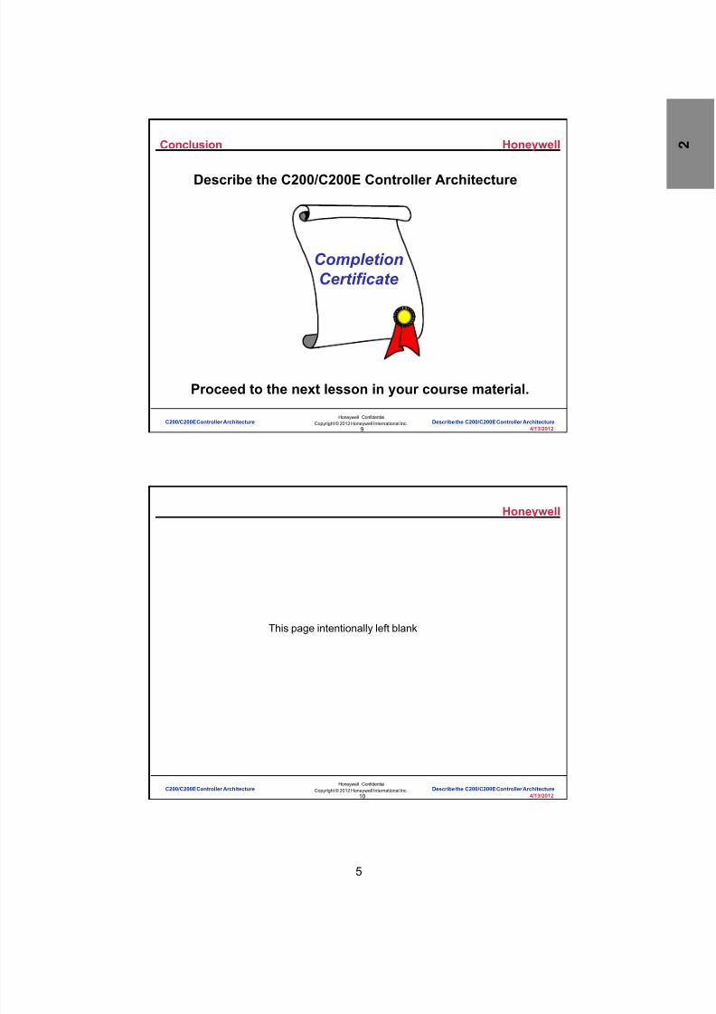
Conclusion
Describe the C200/C200E Controller Architecture
CompletionCertificate
Proceed to the next lesson in your course material.
C200/C200E Controller Architecture Describe the C200/C200E Controller Architecture
Honeywell
Honeywell ConfidentialCopyright © 2012 Honeywell International Inc.
4/13/201210
This page intentionally left blank
C200/C200E Controller Architecture Describe the C200/C200E Controller Architecture

8/9/2019 Student Course Book- Automation
http://slidepdf.com/reader/full/student-course-book-automation 18/1165
6
11
Honeywell ConfidentialCopyright © 2012 Honeywell International Inc.
4/13/2012
Describe the C200/C200E Controller Racksand Redundancy
C200/C200E Controller Architecture Describe the C200/C200E Controller Racks and RedundancyC200/C200E Controller Architecture Describe the C200/C200E Controller Racks and Redundancy
Honeywell
Honeywell ConfidentialCopyright © 2012 Honeywell International Inc.
4/13/201212
Introduction
• In this lesson, you will learn how the C200/C200E controller isnetworked to the server and to remote I/O racks in redundant and non-redundant configurations.
• At the conclusion of this lesson, you will be able to:
– Describe the C200/C200E control processor, communication andredundancy modules
– Explain the C200/C200E network connections and addressing
CP or CPM – Control Processor ModuleCNI – ControlNet InterfaceFTEB – Fault Tolerant Ethernet BridgeRM – Redundancy Module
CNI
AI
AO
AI
DO
AO
AI
DO
DI
Honeywell
CNI M
CP
CNI
CNI
Honeywell
RM
CNI M
CP
CNI
CNI
Honeywell
RM
C200/C200E Controller Architecture Describe the C200/C200E Controller Racks and Redundancy

8/9/2019 Student Course Book- Automation
http://slidepdf.com/reader/full/student-course-book-automation 19/1165
7
Honeywell
Honeywell ConfidentialCopyright © 2012 Honeywell International Inc.
4/13/201213
Topics
• C200/C200E Hardware
• C200/C200E Network Connections and Addressing
C200/C200E Controller Architecture Describe the C200/C200E Controller Racks and Redundancy
Honeywell
Honeywell ConfidentialCopyright © 2012 Honeywell International Inc.
4/13/201214
22
OK
C200 Control Processor (CP)
• 100MHz Power PC 603E processor with 8 MB RAM
– 4 MB (of 8 MB RAM) available for user built control strategies
• 4 MB Flash ROM for storing program
• Lithium battery (or optional rechargeable battery extension module)
• Can support up to 8 I/O chassis and 64 IOMs
• Controller can be redundant or non-redundant
• Double-wide module -- occupies 2 slots on CP rack
C200/C200E Controller Architecture Describe the C200/C200E Controller Racks and Redundancy

8/9/2019 Student Course Book- Automation
http://slidepdf.com/reader/full/student-course-book-automation 20/1165
8
Honeywell
Honeywell ConfidentialCopyright © 2012 Honeywell International Inc.
4/13/201215
C200E Control Processor (CP)
• 150MHz Power PC 603R processor with 32 MB RAM
– 16 MB (of 32 MB RAM) available for user built control strategies
• 8 MB Flash ROM for storing program
• Lithium Battery (or Optional Rechargeable Battery Extension Module)
• Can support up to 8 I/O Chassis and 64 IOMs
• Controller can be Redundant or Non-redundant
• Double-wide Module -- occupies 2 slots on the CP Rack
22
OK
C200/C200E Controller Architecture Describe the C200/C200E Controller Racks and Redundancy
Honeywell
Honeywell ConfidentialCopyright © 2012 Honeywell International Inc.
4/13/201216
NET
ControlNet Interface (CNI)
• Provides the interface to the supervisory network (supervisory CNI)
• Facilitates Peer-to-Peer communication
• Enables remote I/O communication (downlink CNI)
• Each downlink CNI can support up to 24 remote IOMs
• 4 downlink CNIs can be connected to one controller
• Each CNI must have a unique MAC ID on thesame network
C200/C200E Controller Architecture Describe the C200/C200E Controller Racks and Redundancy

8/9/2019 Student Course Book- Automation
http://slidepdf.com/reader/full/student-course-book-automation 21/1165
9
Honeywell
Honeywell ConfidentialCopyright © 2012 Honeywell International Inc.
4/13/201217
Fault Tolerant Ethernet Bridge (FTEB)
FTEB
FTE
ControlNet
CNI
The Device Index(generally, the last
octet of the IP address)is set here
C200/C200E Controller Architecture Describe the C200/C200E Controller Racks and Redundancy
Honeywell
Honeywell ConfidentialCopyright © 2012 Honeywell International Inc.
4/13/201218
Redundancy Module (RM)
• Placed in controller chassis to support redundant controllers
– RM must be in the same position in both racks
– Both RMs are connected by an optical cable
– Switchover between redundant controllers is bumpless
Note: If controller is redundant, then all IOMs must be remote
Redundancy Cable (Fiber Optic)
C200/C200E Controller Architecture Describe the C200/C200E Controller Racks and Redundancy

8/9/2019 Student Course Book- Automation
http://slidepdf.com/reader/full/student-course-book-automation 22/1165
10
Honeywell
Honeywell ConfidentialCopyright © 2012 Honeywell International Inc.
4/13/201219
Question 1: C200/C200E Control Processor
Incorrect. The false statement is "It provides aninterface to the supervisory network." The interfaceto the supervisory network is provided by either the
CNI card or the Fault Tolerant Ethernet Bridge (FTEB).
Click anywhere to continue.
Incorrect. The false statement is "It provides aninterface to the supervisory network." The interfaceto the supervisory network is provided by either the
CNI card or the Fault Tolerant Ethernet Bridge (FTEB).
Click anywhere to continue.
Incorrect. The false statement is "It provides aninterface to the supervisory network." The interfaceto the supervisory network is provided by either the
CNI card or the Fault Tolerant Ethernet Bridge (FTEB).
Click anywhere to continue.
Good job! The false statement is "It provides aninterface to the supervisory network." The interfaceto the supervisory network is provided by either the
CNI card or the Fault Tolerant Ethernet Bridge (FTEB)
Click anywhere to continue.
Correct - Click anywhere to continueIncorrect - Click anywhere to continueYou answered this correctly!
Your answer:The correct answer is:
You did not answer this question completelyYou must answer the question before continuing
Submit Clear
Which of these statements about the control processor (CP) is false ?
22
OK
A) It can support up to 8 I/O chassis and 64 IOMs
B) It is a double-wide module that occupies 2 rack slots
C) It can be redundant
D) It provides an interface to the supervisory network
C200/C200E Controller Architecture Describe the C200/C200E Controller Racks and Redundancy
Honeywell
Honeywell ConfidentialCopyright © 2012 Honeywell International Inc.
4/13/201220
Topics
• C200/C200E Hardware
• C200/C200E Network Connections and Addressing
C200/C200E Controller Architecture Describe the C200/C200E Controller Racks and Redundancy

8/9/2019 Student Course Book- Automation
http://slidepdf.com/reader/full/student-course-book-automation 23/1165
11
Honeywell
Honeywell ConfidentialCopyright © 2012 Honeywell International Inc.
4/13/201221
Non-redundant Controller
TC-FXX102 -- 10-slot rack
TC-PRS021 -- C200Control Processor TC-CCR013 --
ControlNet Interface(CNI), Redundant
Media
TC-FPCXX2--120/240 VACPower Supply
TC-PCIC01 -- ControlNetCommunication InterfaceModule for PC (redundantmedia) (in server)
I/O modules andterminal blocks
ControlNet Cable (TC- KCCxxx) --S upervisory
Terminators --TC-TCXBNC
Taps -- 9904-TPS, R,YS, and YR (4 kinds)
Server (stations not
shown)
(Optional ) T C-CCR013 --CNI to connect to other I/O racks
Controller Chassis
AdditionalRemote I/O
TC-CCR013 -- CNI,Redundant Media
I/O modules andterminal blocks
LAN ConnectionEthernet, TCPIP, etc.
Contr olNet
Series A IO can bein a non-redundantcontroller chassis
C200/C200E Controller Architecture Describe the C200/C200E Controller Racks and Redundancy
Honeywell
Honeywell ConfidentialCopyright © 2012 Honeywell International Inc.
4/13/201222
Redundant Controller
TC-FXX0727 SLOT RACK
Redundant Chassis
Identical ConfigurationModule for module
TC-CCR013 -- CNI,Redundant Media
TC-FPCXX2 --120/240 VACPower Supply
ControlNet Cable (TC-KCCxxx ) -- Supervisory
Terminators --TC-TCXBNC
TC-CCR013 -- CNI toconnect to I/O racks
TC -PRR021 --RedundancyModule
toServer
NO IOMs PERMITTED IN CONTROLLER CHASSIS FOR REDUNDANT
CONFIGURATION!!
NO IOMs PERMITTED IN CONTROLLER CHASSIS FOR REDUNDANT
CONFIGURATION!! (IOLIM and FIM are exceptions)
ControlNet Cable -- I/OComm
to IOChassis
GN- KRRxx1 -- RedundancyCable (Fiber Optic)
TC-PRS021 -- C200Control Processor TC-FXX072 – 7-slot rack
C200/C200E Controller Architecture Describe the C200/C200E Controller Racks and Redundancy

8/9/2019 Student Course Book- Automation
http://slidepdf.com/reader/full/student-course-book-automation 24/1165
12
Honeywell
Honeywell ConfidentialCopyright © 2012 Honeywell International Inc.
4/13/201223
Address Settings - Non-redundant C200/C200E
C N I
C N I
C N I
Server PCIC
23
03
0101
03
C N
I
C N I
02
C N I
05
C N I
04 C 2 0 0 /
C 2 0 0 E
C 2 0 0 /
C 2 0 0 E
PCIC must be 23
(24 for redundancy)Supervisory CNIs must be odd 1-19IO CNets should leave no gap
Use even and odd numbersAll CNets must have a CNI = 1
(network update time)
C200/C200E Controller Architecture Describe the C200/C200E Controller Racks and Redundancy
Honeywell
Honeywell ConfidentialCopyright © 2012 Honeywell International Inc.
4/13/201224
Address Settings – Redundant C200/C200E
01
C N I
Server PCIC C
N I
C N I
C N I
C N I
C N I
R M
R MServerB
PCIC
A
24
23
03
01
0101
03
C N I C
N I
C N I
C N I
05
05
07
C 2 0 0 /
C 2 0 0 E
C 2 0 0 /
C 2 0 0 E
C 2 0 0 /
C 2 0 0 E
04
23 & 24 for ServersCNIs in C200 chassis must be the same odd number
Second one powered on uses virtual (+1) address
IO CNet – Assign 3 to a CNI in a remote chassisDuring a failover, it controls Network Update TimeIO chassis are not redundant, so use odd & even
No gaps
C200/C200E Controller Architecture Describe the C200/C200E Controller Racks and Redundancy
8/9/2019 Student Course Book- Automation
http://slidepdf.com/reader/full/student-course-book-automation 25/1165
13
Honeywell
Honeywell ConfidentialCopyright © 2012 Honeywell International Inc.
4/13/201225
FTEB
ServerA
F T E B
C N I
C N I
F T E B
C N I
C N I
R M
R MerverB
01
01
03
04
C N I F
T E B
C N I
C N I
05
05
07
C 2 0 0 /
C 2 0 0 E
C 2 0 0 /
C 2 0 0 E
C 2 0 0 /
C 2 0 0 E
Switch
Switch
01
02
03
C200/C200E Controller Architecture Describe the C200/C200E Controller Racks and Redundancy
Honeywell
Honeywell ConfidentialCopyright © 2012 Honeywell International Inc.
4/13/201226
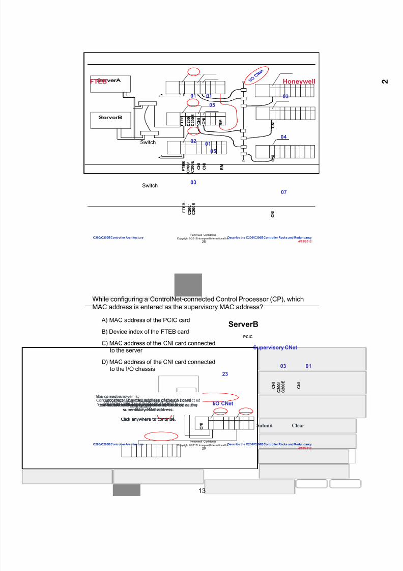
Question 2: MAC Addresses
Incorrect. The MAC address of the CNI cardconnected to the server should be entered as the
supervisory MAC address.
Click anywhere to continue.
Incorrect. The MAC address of the CNI cardconnected to the server should be entered as the
supervisory MAC address.
Click anywhere to continue.
Correct! The MAC address of the CNI card connect edto the server should be entered as the supervisory
MAC address.
Click anywhere to continue.
Incorrect. The MAC address of the CNI cardconnected to the server should be entered as the
supervisory MAC address.
Click anywhere to continue.
Correct - Click anywhere to continueIncorrect - Click anywhere to continueYou answered this correctly!
Your answer:The correct answer is:
You did not answer this question completelyYou must answer the question before
continuing
Submit Clear
While configuring a ControlNet-connected Control Processor (CP), whichMAC address is entered as the supervisory MAC address?
A) MAC address of the PCIC card
B) Device index of the FTEB card
C) MAC address of the CNI card connectedto the server
D) MAC address of the CNI card connectedto the I/O chassis 03
C N I
C 2 0 0 /
C 2 0 0 E
ServerBPCIC
2301
C N I
C N I
I/O CNet
Supervisory CNet
C200/C200E Controller Architecture Describe the C200/C200E Controller Racks and Redundancy

8/9/2019 Student Course Book- Automation
http://slidepdf.com/reader/full/student-course-book-automation 26/1165
14
Honeywell
Honeywell ConfidentialCopyright © 2012 Honeywell International Inc.
4/13/201227
Summary
• When you connect the C200/C200E controller to the server and toremote I/O racks in non-redundant and redundant configurations,remember:
– The double-wide control processor (CP) supports up to 8 I/O chassis and 64IOMs.
– ControlNet Interface (CNI) modules provide interfaces to the I/O ControlNetand the Supervisory ControlNet.
– Redundant controllers require all IOMs be configured remotely.
– All devices on the same network must have unique MAC addresses.
– Redundant CNI cards must be addressed with the same odd number.
– Redundant FTEBs must be addressed differently with the primary having anodd number and the secondary having the next highest even number.
C200/C200E Controller Architecture Describe the C200/C200E Controller Racks and Redundancy
Honeywell
Honeywell ConfidentialCopyright © 2012 Honeywell International Inc.
4/13/201228
Conclusion
Describe the C200 Controller Racks and Redundancy
CompletionCertificate
Proceed to the next lesson in your course material.
C200/C200E Controller Architecture Describe the C200/C200E Controller Racks and Redundancy

8/9/2019 Student Course Book- Automation
http://slidepdf.com/reader/full/student-course-book-automation 27/1165
15
29
Honeywell ConfidentialCopyright © 2012 Honeywell International Inc.
4/13/2012
Describe the C200/C200E I/O Modules
C200/C200E Controller Architecture Describe the C200/C200E I/O ModulesC200/C200E Controller Architecture Describe the C200/C200E I/O Modules
Honeywell
Honeywell ConfidentialCopyright © 2012 Honeywell International Inc.
4/13/201230
Introduction
• In this lesson you will learn about the standard C200/C200E input/output(I/O) modules and their applications.
• At the conclusion of this lesson, you will be able to:
– List the standard I/O types that are compatible with the Experion system
– Identify the application for each type of I/O module
Rail I/OSeries A
GI/IS Rail I/OSeries H
PM I/O
C200/C200E Controller Architecture Describe the C200/C200E I/O Modules

8/9/2019 Student Course Book- Automation
http://slidepdf.com/reader/full/student-course-book-automation 28/1165
16
Honeywell
Honeywell ConfidentialCopyright © 2012 Honeywell International Inc.
4/13/201231
Chassis - Series A Input/Output Modules
• Chassis I/O (also referred to as Series A I/O) has the followingattributes: – Compact Size – may reside in either the controller rack or remote I/O rack – Diagnostic and non-diagnostic modules available (DI & DO modules) – IOM configurable through Control Builder – Removable wiring hood – Can be removed and replaced under power – All modules have a form factor of 5” X 5” – Redundancy not supported
• Module Types: – HART / Non-HART Analog Input – HART / Non-HART Analog Output
– Digital Input (with and without Diagnostics) – Digital Output (with and without Diagnostics) – Resistance Temperature Detector (RTD) Input – Thermocouple Input
C200/C200E Controller Architecture Describe the C200/C200E I/O Modules
Honeywell
Honeywell ConfidentialCopyright © 2012 Honeywell International Inc.
4/13/201232
-+ +
-1 2
3
278
IOM types:
Terminal BaseGateway
DIN Rail
AI- Analog Input AO- Analog Output DI- Digital Input DO- Digital Output
Series A Rail I/O
• Modular connections – slide rail
• 8 terminal bases can beconnected to a single gateway
• Gateway provides link to theControlNet
• Analog I/O, digital I/O,thermocouple and RTD
Redundancy is notsupported.
C200/C200E Controller Architecture Describe the C200/C200E I/O Modules

8/9/2019 Student Course Book- Automation
http://slidepdf.com/reader/full/student-course-book-automation 29/1165
17
Honeywell
Honeywell ConfidentialCopyright © 2012 Honeywell International Inc.
4/13/201233
Server
Rail I/O Modules - Series H
Controller
Supervisory ControlNet
Gateway
I/O ControlNet
Fiber Optic
Cable
I/O ControlNet
C O M M O D P W R
1 2 3 4
+V-V+V-V
C o n trol Net R e p e ate rA d a p ter
TC- P B F O 0 1
E
x C o n trol NetFi b e r M o duleTC- P M F O 0 1
E
x
Cha n 1
Rec v Re c vXmi t X m it
Cha n 2
C o n trol NetFi ber ModuleTC- P M F O 0 1
E
x
Cha n 1
Rec v R e c vXmi t X m it
Cha n 2
1 2 3 4
+V-V+V-V
C O M M O D P W R
C o n trol Net R e p e ate rA d a p terTC- P B F O 0 1
E C o n trol NetFi ber ModuleTC- P M F O 0 1
E x
Cha n 1
Rec v R e c vXmi t X m it
Cha n 2
C o n trol Net Fib e r M o duleTC- P M F O 0 1
E x
Cha n 1
Rec vRec v
Xmi tXmi t
Cha n 2
A B
-++
-12
1 2 4
V+V-V+V-
TC- P G C N 1 1
E x
Non-HazardousArea
HazardousArea
Repeater/Adapter C O M M O D P W R
1 2 3 4
+V-V+V-V
C o n trol Net R e p e ate rA d a p ter
TC- P B F O 0 1
E
x Co n trol Net Fi b e r M o duleTC- P M F O 0 1
E
x
Cha n 1
Rec v Re c vXmi t X m it
Cha n 2
C o n trol NetFiber ModuleTC- P M F O 0 1
E
x
Cha n 1
Rec v R e c vXmi t X m it
Cha n 2
1 2 3 4
+V-V+V-V
C O M M O D P W R
C o n trol Net R e p e ate rA d a p terTC- P B F O 0 1
E C o n trol Net Fiber Module
TC- P M F O 0 1E x
Cha n 1
Rec v Re c vXmi t X m it
Cha n 2
C o n trol NetFi b e r M o duleTC- P M F O 0 1
E x
Cha n 1
Rec vRec v
Xmi tXmi t
Cha n 2
Repeater/Adapter Fiber Modules Fiber Modules
CNIModule
Series H Rail I/O
• Galvanically isolated• Intrinsically safe
Redundancy is notsupported.
C200/C200E Controller Architecture Describe the C200/C200E I/O Modules
Honeywell
Honeywell ConfidentialCopyright © 2012 Honeywell International Inc.
4/13/201234
PM I/O
Process Manager I/O (PM I/O)
• Requires a PM I/O Link Interface Module(IOLIM) in the same rack as theC200/C200E
• Redundant IOLIMs are supported withredundant C200/C200Es
• PM I/O can be redundant
• PM I/O includes AI, AO, DI, DO, RTD, T/C,DI SOE
• PM I/O requires a separate board to acceptfield wiring. This board is called a FieldTermination Assembly (FTA).
• PM I/O can be configured remotely up to8km using an fiber optic IOLINK Extender
C200/C200E Controller Architecture Describe the C200/C200E I/O Modules

8/9/2019 Student Course Book- Automation
http://slidepdf.com/reader/full/student-course-book-automation 30/1165
18
Honeywell
Honeywell ConfidentialCopyright © 2012 Honeywell International Inc.
4/13/201235
Serial Interface Module
Honeywell
NET OK NET
Serial Interface Module
ADAPTER
SERIALINTERFACE
FTAMODBUS(16 Array
Channels)
ModbusCompatibleSubsystem
Allen-BradleyCompatibleSubsystem
SERIALINTERFACE
FTA A/B
(16 ArrayChannels)
SIM FTAPower Adapter
C200/C200E Controller Architecture Describe the C200/C200E I/O Modules
Honeywell
Honeywell ConfidentialCopyright © 2012 Honeywell International Inc.
4/13/201236
Question 1: I/O Application
Incorrect. Series H I/O modules are specificallydesigned for unsafe environments.
Click anywhere to continue.
Incorrect. Series H I/O modules are specificallydesigned for unsafe environments.
Click anywhere to continue.
Correct! Series H I/O modules are specificallydesigned for unsafe environments.
Click anywhere to continue.
Correct - Click anywhere to continueIncorrect - Click anywhere to continueYou answered this correctly!
Your answer: The correct answer is:
You did not answer this question completelyYou must answer the question beforecontinuing
Submit Clear
Which I/O module can be used in a hazardous environment?
A) Chassis I/O
B) Serial Interface
C) Series H I/OHoneywell
NET OK NET
Rail I/O Modules - Series H
Gateway
A B
-++
-12
1 2 4
V+V-V+V-
TC-PGCN11
E x
C200/C200E Controller Architecture Describe the C200/C200E I/O Modules

8/9/2019 Student Course Book- Automation
http://slidepdf.com/reader/full/student-course-book-automation 31/1165
19
Honeywell
Honeywell ConfidentialCopyright © 2012 Honeywell International Inc.
4/13/201237
Question 2: I/O Redundancy
No. PM I/O modules are the only standardI/O modules that are available in a redundant
configuration.
Click anywhere to continue.
Yes! PM I/O modules are the only standardI/O modules that are available in a redundant
configuration.
Click anywhere to continue.
No. PM I/O modules are the only standardI/O modules that are available in a redundant
configuration.
Click anywhere to continue.
Correct - Click anywhere to continueIncorrect - Click anywhere to continueYou answered this correctly!
Your answer:The correct answer is:
You did not answer this question completelyYou must answer the question beforecontinuing
Submit Clear
Which I/O module will support redundancy?
A) Chassis I/O
B) PM I/O
C) Series H I/O
Rail I/O Modules - Series H
Gateway
A B
-+ +
-12
1 2 4
V+V-V+V-
TC-PGCN11
E x
PM I/O
Honeywell
NET OK NET
C200/C200E Controller Architecture Describe the C200/C200E I/O Modules
Honeywell
Honeywell ConfidentialCopyright © 2012 Honeywell International Inc.
4/13/201238
Summary
• The standard I/O types compatible with the Experion system are:
– Chassis Series A I/O modules, which can be installed in the same chassisas the C200/C200E (if the C200/C200E is not redundant) or a remote I/Ochassis.
– Series A Rail I/O modules, which include analog I/O, digital I/O,thermocouples, and RTD.
– Series H Rail I/O modules, which are intrinsically safe for use in hazardousenvironments.
– PM I/O modules which include AI, AO, DI, DO, RTD, T/C, and DI SOE.
– Serial Interface modules which interface to Allen-Bradley and Modbussubsystems.
C200/C200E Controller Architecture Describe the C200/C200E I/O Modules

8/9/2019 Student Course Book- Automation
http://slidepdf.com/reader/full/student-course-book-automation 32/1165
20
Honeywell
Honeywell ConfidentialCopyright © 2012 Honeywell International Inc.
4/13/201239
Conclusion
Describe the C200/C200E I/O Modules
CompletionCertificate
Proceed to the next lesson in your course material.
C200/C200E Controller Architecture Describe the C200/C200E I/O Modules
Honeywell
Honeywell ConfidentialCopyright © 2012 Honeywell International Inc.
4/13/201240
This page intentionally left blank
C200/C200E Controller Architecture Describe the C200/C200E I/O Modules
8/9/2019 Student Course Book- Automation
http://slidepdf.com/reader/full/student-course-book-automation 33/1165
1
1
Honeywell ConfidentialCopyright © 2012 Honeywell International Inc.
4/13/2012
Describe the Main Features of the Series CSystem
C300 Controller Architecture - Part 1 of 2 Describe the Main Features of the Series C SystemC300 Controller Architecture - Part 1 of 2 Describe the Main Features of the Series C System
Honeywell
Honeywell ConfidentialCopyright © 2012 Honeywell International Inc.
4/13/20122
Topics
• Series C Deliverables
• Key features of Series C hardware
• Performance targets
C300 Controller Architecture - Part 1 of 2 Describe the Main Features of the Series C System

8/9/2019 Student Course Book- Automation
http://slidepdf.com/reader/full/student-course-book-automation 34/1165
2
Honeywell
Honeywell ConfidentialCopyright © 2012 Honeywell International Inc.
4/13/20123
Series C Deliverables
• Products and Functions delivered underthe Series C Umbrella include: – Series C I/O – Series C FIM – Profibus Gateway Module (PGM) – C300 Controller – Control Firewall
• Related Deliverables include: – FTE Bridge firmware that supports C300
connections to selected Series A I/O• Allows FTE Bridge firmware to be
upgraded from a R300 or later system• The C300 Firmware should match the
release of the Experion Server – Power System
C300 Controller Architecture - Part 1 of 2 Describe the Main Features of the Series C System
Honeywell
Honeywell ConfidentialCopyright © 2012 Honeywell International Inc.
4/13/20124
Series C Deliverables
• Products delivered in Series C Release – C300 Controller
• 50 ms and 20 ms• Initial release C300 20 ms supported
for Turbo machinery Controls – Series C I/O
• Analog Input – HART, Non-HART• Analog Output – HART, Non-HART• Digital Input & DI-SOE• Digital Output• Low Level Mux Input• Speed Protection Module (SPM)
– Only with C300 20 ms• Servo Valve Position Module (SVPM)
– Only with C300 20 ms – Fieldbus Interface Module (FIM4, FIM8) – Profibus Gateway Module (PGM) – Control Firewall – Power System
C300 Controller Architecture - Part 1 of 2 Describe the Main Features of the Series C System
8/9/2019 Student Course Book- Automation
http://slidepdf.com/reader/full/student-course-book-automation 35/1165
3
Honeywell
Honeywell ConfidentialCopyright © 2012 Honeywell International Inc.
4/13/20125
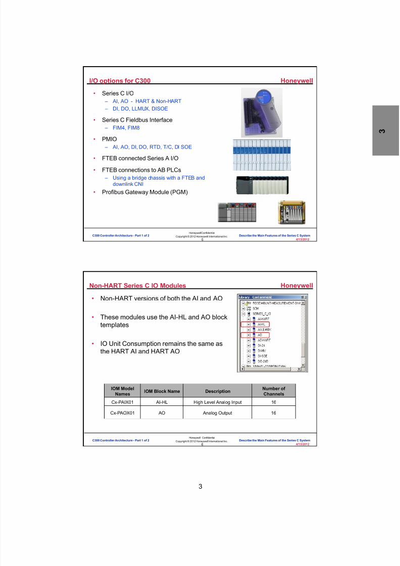
I/O options for C300
• Series C I/O – AI, AO - HART & Non-HART – DI, DO, LLMUX, DISOE
• Series C Fieldbus Interface – FIM4, FIM8
• PMIO – AI, AO, DI, DO, RTD, T/C, DI SOE
• FTEB connected Series A I/O
• FTEB connections to AB PLCs – Using a bridge chassis with a FTEB and
downlink CNI
• Profibus Gateway Module (PGM)
C300 Controller Architecture - Part 1 of 2 Describe the Main Features of the Series C System
Honeywell
Honeywell ConfidentialCopyright © 2012 Honeywell International Inc.
4/13/20126
Non-HART Series C IO Modules
• Non-HART versions of both the AI and AO
• These modules use the AI-HL and AO blocktemplates
• IO Unit Consumption remains the same asthe HART AI and HART AO
IOM ModelNames IOM Block Name Description Number of
Channels
Cx-PAIX01 AI-HL High Level Analog Input 16
Cx-PAOX01 AO Analog Output 16
C300 Controller Architecture - Part 1 of 2 Describe the Main Features of the Series C System

8/9/2019 Student Course Book- Automation
http://slidepdf.com/reader/full/student-course-book-automation 36/1165
4
Honeywell
Honeywell ConfidentialCopyright © 2012 Honeywell International Inc.
4/13/20127
Question 1: Series C Deliverables
Incorrect. The false statement is " New FTEBridge firmware is required but it cannot be
upgraded from a R300 system."
Click anywhere to continue.
Incorrect. The false statement is " New FTEBridge firmware is required but it cannot be
upgraded from a R300 system."
Click anywhere to continue.
Correct! The false statement is " New FTE Bridgefirmware is required but it cannot be upgraded
from a R300 system."
Click anywhere to continue.
Correct - Click anywhere to continueIncorrect - Click anywhere to continueYou answered this correctly!
Your answer:The correct answer is:
You did not answer this question completelyYou must answer the question beforecontinuing
Submit Clear
Which of these statements about the Series C deliverables is false ?
A) Series C deliverables include Series C I/O, C300,Series C FIM and Control Firewall
B) Series C deliverables include a new Power System
C) New FTE Bridge firmware is required but cannotbe upgraded from a R310 system
C300 Controller Architecture - Part 1 of 2 Describe the Main Features of the Series C System
Honeywell
Honeywell ConfidentialCopyright © 2012 Honeywell International Inc.
4/13/20128
Topics
• Series C Deliverables
• Key features of Series C hardware
• Performance targets
C300 Controller Architecture - Part 1 of 2 Describe the Main Features of the Series C System

8/9/2019 Student Course Book- Automation
http://slidepdf.com/reader/full/student-course-book-automation 37/1165
5
Honeywell
Honeywell ConfidentialCopyright © 2012 Honeywell International Inc.
4/13/20129
Packaging - Overview
• “Series C” is the term used to describe the newstyling for the C300 controller and associatedmodules
• The Series C hardware was designed to bespace efficient – “Designed Vertical” – No electronic card files – “Zero Footprint” power system does not impact
module space – Designed to offer >30% reductions in space
• Combines I/O Processor and Field Terminationsinto one Assembly – Fewer components providing higher MTBF
and Availability
C300 Controller Architecture - Part 1 of 2 Describe the Main Features of the Series C System
Honeywell
Honeywell ConfidentialCopyright © 2012 Honeywell International Inc.
4/13/201210
Key Attributes
• Environmental ratings – Temperature: 0 -60 Deg C – EMI/RFI:15 V/M External to cabinet with doors closed – Vibration: Frequency 10 to 60 Hz, Acceleration 0.5 g max, Displacement 0.1
inch – Class 1 Div 2/Zone 2 interface & mounting support
• Approvals Support (CE, FM, CSA, ATEX, etc.) – No plans for UL certification of complete system
• Corrosion protected models• All Series C components can be mixed and matched in cabinet• Electronics mounted to IOTA
– Module Removal and Insertion Under Power (RIUP)
– Reduces footprint• Packaged cabinet solution
– Similar to TPS Process Manager today
C300 Controller Architecture - Part 1 of 2 Describe the Main Features of the Series C System

8/9/2019 Student Course Book- Automation
http://slidepdf.com/reader/full/student-course-book-automation 38/1165
6
Honeywell
Honeywell ConfidentialCopyright © 2012 Honeywell International Inc.
4/13/201211
Key Attributes
• “Designed Vertical” – The modules are set at an 18 degree
angle for greater heat dissipation• Reduces “hot spots”
– More Efficient Field Wiring• Top/Bottom Wiring Entry• More Natural Terminations• No Severe Wire Bends
• Space Efficient Design – Comparable to highest density current
competitive offerings
• Modular Approach
– Removable Terminal Blocks
C300 Controller Architecture - Part 1 of 2 Describe the Main Features of the Series C System
Honeywell
Honeywell ConfidentialCopyright © 2012 Honeywell International Inc.
4/13/201212
Mechanical Keying
• The Series C IO Modules all have the sameform factor. To prevent insertion of the wrongmodule into the wrong IOTA, the modules areequipped with tabs or keys which correspond toslots on the IOTA.
Keys
KeySlots
C300 Controller Architecture - Part 1 of 2 Describe the Main Features of the Series C System

8/9/2019 Student Course Book- Automation
http://slidepdf.com/reader/full/student-course-book-automation 39/1165
7
Honeywell
Honeywell ConfidentialCopyright © 2012 Honeywell International Inc.
4/13/201213
New Terminology
IOTA Support
IOTA Carrier
IOTA (Input/Output Termination Assembly)
IOM (Input/Output Module)
C300 Controller Architecture - Part 1 of 2 Describe the Main Features of the Series C System
Honeywell
Honeywell ConfidentialCopyright © 2012 Honeywell International Inc.
4/13/201214
Main Components
• Mounting concept: – Single cabinet side for electronics
and terminations – Cable tray mounted carrier/IOTA with:
• Replaceable Module• Power and Communication
Connectors• Field Wiring Connections
• Vertical stacking of elements – Natural flow of field wiring
• Channel mount – Channel is like PM FTA channel – Channel is not the same as FTA and
cannot be used for Series C mounting
C300 Controller Architecture - Part 1 of 2 Describe the Main Features of the Series C System

8/9/2019 Student Course Book- Automation
http://slidepdf.com/reader/full/student-course-book-automation 40/1165
8
Honeywell
Honeywell ConfidentialCopyright © 2012 Honeywell International Inc.
4/13/201215
New Cabinet Design
PowerSupply Area
I/O Rail Area
Batteries/BatteryCharger
C300 Controller Architecture - Part 1 of 2 Describe the Main Features of the Series C System
Honeywell
Honeywell ConfidentialCopyright © 2012 Honeywell International Inc.
4/13/201216
Question 2: Packaging
Incorrect! All of the above statements are true andmake Series C a more space efficient design.
Click anywhere to continue.
Incorrect! All of the above statements are true andmake Series C a more space efficient design.
Click anywhere to continue.
Incorrect! All of the above statements are true andmake Series C a more space efficient design.
Click anywhere to continue.
Correct! All of the above statements are true andmake Series C a more space efficient design.
Click anywhere to continue.
Correct - Click anywhere to continueIncorrect - Click anywhere to continueYou answered this correctly!
Your answer: The correct answer is:
You did not answer this question completelyYou must answer the question beforecontinuing
Submit Clear
What factors contribute to the Series C space-efficient design? A) Designed Vertical
B) No electronic card files
C) Power system does not occupy footprint
D) All of the above
C300 Controller Architecture - Part 1 of 2 Describe the Main Features of the Series C System

8/9/2019 Student Course Book- Automation
http://slidepdf.com/reader/full/student-course-book-automation 41/1165
9
Honeywell
Honeywell ConfidentialCopyright © 2012 Honeywell International Inc.
4/13/201217
Question 3: Terminology
Incorrect. The term "CPM" is not a Series Chardware terminology and is used when
referring to a C200 controller.
Click anywhere to continue.
Incorrect. The term "CPM" is not a Series Chardware terminology and is used when
referring to a C200 controller.
Click anywhere to continue.
Incorrect. The term "CPM" is not a Series Chardware terminology and is used when
referring to a C200 controller.
Click anywhere to continue.
Incorrect. The term "CPM" is not a Series Chardware terminology and is used when
referring to a C200 controller.
Click anywhere to continue.
Correct! The term "CPM" is not a Series Chardware terminology and is used when
referring to a C200 controller.
Click anywhere to continue.
Correct - Click anywhere to continueIncorrect - Click anywhere to continueYou answered this correctly!
Your answer: The correct answer is:
You did not answer this question completelyYou must answer the question before
continuing
Submit Clear
Which of the following is not a Series C hardware terminology?
A) IOTA Support
B) IOTA Carrier
C) IOTA
D) IOM
E) CPM
C300 Controller Architecture - Part 1 of 2 Describe the Main Features of the Series C System
Honeywell
Honeywell ConfidentialCopyright © 2012 Honeywell International Inc.
4/13/201218
Topics
• Series C Deliverables
• Key features of Series C hardware
• Performance targets
C300 Controller Architecture - Part 1 of 2 Describe the Main Features of the Series C System

8/9/2019 Student Course Book- Automation
http://slidepdf.com/reader/full/student-course-book-automation 42/1165
10
Honeywell
Honeywell ConfidentialCopyright © 2012 Honeywell International Inc.
4/13/201219
Performance “Targets”
FEATURE C300 (20ms) C300 (50ms)
Fault-Tolerant Ethernet
FTE Nodes per Community 65 3301 (200)
Non-FTE Nodes per Community 200
ACE
No. ACE per Server 7
Controller
No. Controlle rs per Server (C200 or C300) 2 20
Latency Analog Digital
250 ms100 ms
Notes:1. 330 nodes per community if no FTEBs are present; 200 nodes per community with FTEBs.
C300 Controller Architecture - Part 1 of 2 Describe the Main Features of the Series C System
Honeywell
Honeywell ConfidentialCopyright © 2012 Honeywell International Inc.
4/13/201220
Limitations
Peer-to-Peer PM I/O
Series C
I/O
I
HLA
OKOK
NO
NO
NO
M
CP
Honeywell
FTEB L
IOMI
M
FI
OK
OK
C300
FIM
Series C FIM (FIM4)- OK w/o C300
Series A FIM (FIM2)- Requires C200 (CPM)
• The following is not supported with C300: – Peer-to-Peer communications with FTEB-based IOLIMs – Series C and PM I/O cannot be mixed on same I/O Link
• The following architectures are not supported: – C200/C200E Peer-to-Peer communication with Series C FIM4/FIM8
modules
– C300 Peer-to-Peer communications with Series A FIM (FIM2) modules
C300 Controller Architecture - Part 1 of 2 Describe the Main Features of the Series C System

8/9/2019 Student Course Book- Automation
http://slidepdf.com/reader/full/student-course-book-automation 43/1165
11
Honeywell
Honeywell ConfidentialCopyright © 2012 Honeywell International Inc.
4/13/201221
Question 4: Rules
Incorrect. All of the above statementsare true about the Series C system.
Click anywhere to continue.
Incorrect. All of the above statementsare true about the Series C system.
Click anywhere to continue.
Incorrect. All of the above statementsare true about the Series C system.
Click anywhere to continue.
Incorrect. All of the above statementsare true about the Series C system.
Click anywhere to continue.
Correct! All of the above statementsare true about the Series C system.
Click anywhere to continue.
Correct - Click anywhere to continueIncorrect - Click anywhere to continueYou answered this correctly!
Your answer:The correct answer is:
You did not answer this question completelyYou must answer the question beforecontinuing
Submit Clear
Which of the following statements is true about a Series C system? A) Peer-to-peer communication with FTEB based
IOLIMs is not supported
B) Series C I/O and PM I/O cannot be mixed on thesame I/O Link
C) C200 Peer-to-peer communications with Series CFIM modules is not supported
D) C300 Peer-to-peer communications with FTEB-based (Series A) FIM modules is not supported
E) All of the above
C300 Controller Architecture - Part 1 of 2 Describe the Main Features of the Series C System
Honeywell
Honeywell ConfidentialCopyright © 2012 Honeywell International Inc.
4/13/201222
• Series C hardware includes: – Series C I/O (HART and Non-HART AI and AO, DI, DO, LLMUX, DISOE) – Series C FIM (FIM4, FIM8) – Profibus Gateway Module – C300 Controller – Control Firewall
• Series C is a space efficient design that combines I/O processor andfield termination into one assembly.
• Series C electronics are mounted to IOTAs reducing footprint andsupporting module removal and insertion under power (RIUP).
• C300 controller supports Series C, Series A, and PM I/O, Series CFieldbus interface, PGM, and FTEB connections to AB PLCs viaDownlink CNI.
• 20 C300 controllers are supported per server.• C300 Peer-to-Peer communications with FTEB-based IOLIMs is notsupported.
• Series C and PM I/O cannot be mixed on the same I/O link.
Summary
C300 Controller Architecture - Part 1 of 2 Describe the Main Features of the Series C System

8/9/2019 Student Course Book- Automation
http://slidepdf.com/reader/full/student-course-book-automation 44/1165
12
Honeywell
Honeywell ConfidentialCopyright © 2012 Honeywell International Inc.
4/13/201223
Conclusion
Describe the main features of the Series C system
CompletionCertificate
Proceed to the next lesson in your course material.
C300 Controller Architecture - Part 1 of 2 Describe the Main Features of the Series C System
Honeywell
Honeywell ConfidentialCopyright © 2012 Honeywell International Inc.
4/13/201224
This page intentionally left blank
C300 Controller Architecture - Part 1 of 2 Describe the Main Features of the Series C System

8/9/2019 Student Course Book- Automation
http://slidepdf.com/reader/full/student-course-book-automation 45/1165
13
25
Honeywell ConfidentialCopyright © 2012 Honeywell International Inc.
4/13/2012
Describe the Architecture of Series C System
C300 Controller Architecture - Part 1 of 2 Describe the Architecture of Series C SystemC300 Controller Architecture - Part 1 of 2 Describe the Architecture of Series C System
Honeywell
Honeywell ConfidentialCopyright © 2012 Honeywell International Inc.
4/13/201226
RedundantGlobal Database & Historian
Experion Server
Investment Protectionfor TPS/TDC
Experion on LCN
IntegratedSupervisory Control
ACE
Regulatory, LogicSequential & Model
Based Controls
C300/C200 & Profit Loop
ProcessManager
BasicController
Plant AssetManagement
Asset Manager
Plant WideData
WarehousePHD
Remote OperationsExperion Station
Video as a Process Sensor Digital Video Manager
Casual User
Secure Read OnlyProcess Display
Web Server eServer
Desktop
Accessfor BusinessApplications
Web Browsers
Web-based Human InterfaceExperion Station
ASM Operator Effectiveness
Multivariable Controland Optimization
Profit Suite
Field MobilityMobile PKS
WirelessAccess
Redundant and/orRemote I/O
ErgonomicOperator Consoles
Icon Series
Advanced Applications Network
Business Network
Field RoundsAutomation
IntelaTrac PKS
Local Control Network
Video Ethernet
Advanced Enterprise Wide
ApplicationsBusiness FLEX
Workcenter POMS, OptiVISION
Firewall
Supervisory Control Network
WirelessTransmitters
SIL 3 Safety SystemSafety Manager
Precision Measurementand Control
Quality Control System
Integrated
PhysicalSecurity
EnterpriseBuilding
Integrator
Plant SimulationUniSim
Experion Platform Architecture
Focus of this Presentation
C300 Controller Architecture - Part 1 of 2 Describe the Architecture of Series C System

8/9/2019 Student Course Book- Automation
http://slidepdf.com/reader/full/student-course-book-automation 46/1165
14
Honeywell
Honeywell ConfidentialCopyright © 2012 Honeywell International Inc.
4/13/201227
Series C Architecture
AB PLCsPoint to point data usingexchange blocks
In this release,all Series A IOMs aresupported.
C300 Controller Architecture - Part 1 of 2 Describe the Architecture of Series C System
Honeywell
Honeywell ConfidentialCopyright © 2012 Honeywell International Inc.
4/13/201228
Profibus Gateway Module Architecture
ProcessControllers
Rack I/OSeries A
ProfibusI/O Options
Experion Server
FTE
C300
C200
SST Card
PGM
C300 Controller Architecture - Part 1 of 2 Describe the Architecture of Series C System

8/9/2019 Student Course Book- Automation
http://slidepdf.com/reader/full/student-course-book-automation 47/1165
15
Honeywell
Honeywell ConfidentialCopyright © 2012 Honeywell International Inc.
4/13/201229
Profibus Gateway Module (PGM)
• Series C Profibus Gateway Module (PGM) is used to
connect Profibus devices to a C300 controller – Each C300 Controller supports connections to 2 PGMs – Each PGM can be connected to a single C300 Controller – Each PGM supports 2 Profibus Network Links (PBLink)
• Each PGM link supports up to 124 Profibus devices(slaves)
• Uses Profibus DP protocol to communicate withdevices
– PGMs can optionally be Redundant• Redundant PGMs are on separate IOTAs
– New PDA protocol supports IO Data Communicationbetween C300 and PGM
• Profibus Configuration Tool is integrated into ControlBuilder
• New Profibus Device & Channel Blocks in C300
C300 Controller Architecture - Part 1 of 2 Describe the Architecture of Series C System
Honeywell
Honeywell ConfidentialCopyright © 2012 Honeywell International Inc.
4/13/201230
Question 1: Architecture
Correct! The false statement is " Series C FIM is
connected to L1 or L2 Cisco switch". The Series CFIM is the Fieldbus interface module whichconnects to the Control Firewall via FTE.
Click anywhere to continue.
Incorrect. The false statement is " Series C FIM is
connected to L1 or L2 Cisco switch". The Series CFIM is the Fieldbus interface module whichconnects to the Control Firewall via FTE.
Click anywhere to continue.
Incorrect. The false statement is " Series C FIM is
connected to L1 or L2 Cisco switch". The Series CFIM is the Fieldbus interface module whichconnects to the Control Firewall via FTE.
Click anywhere to continue.
Incorrect. The false statement is " Series C FIM is
connected to L1 or L2 Cisco switch". The Series CFIM is the Fieldbus interface module whichconnects to the Control Firewall via FTE.
Click anywhere to continue.
Correct - Click anywhere to continueIncorrect - Click anywhere to continueYou answered this correctly!
Your answer: The correct answer is:
You did not answer this question completelyYou must answer the question beforecontinuing
Submit Clear
Which of the following statements is not true about the Series C Architecture? A) Series C FIM is connected to L1 or L2 switch
B) Serial Interface, Pulse Input, Device Net Interfaceand Profibus Interface Series A I/O's are connectedto Control Firewall using FTEB
C) Allen Bradely PLCs can also be connected to a rack,and then to the Control Firewall using an FTEB
D) All of the above
C300 Controller Architecture - Part 1 of 2 Describe the Architecture of Series C System

8/9/2019 Student Course Book- Automation
http://slidepdf.com/reader/full/student-course-book-automation 48/1165
16
Honeywell
Honeywell ConfidentialCopyright © 2012 Honeywell International Inc.
4/13/201231
Summary
• Control Firewalls are connected to Level 1 or Level 2 switches• The C300 Controller is connected to the Control Firewall using FTE
• The Series C FIMs (4 & 8) are the Fieldbus interfaces. They alsoconnect to the Control Firewall via FTE
• The PGM is the Profibus interface. This module also connects to theControl Firewall via FTE
• Series A Rack IO connects to the C300 through the Control Firewallusing an FTEB – This rack is connected to the Control Firewall using an FTEB and via FTE
• Allen Bradley PLCs can also be connected to a Rack, and then to theControl Firewall using an FTEB
C300 Controller Architecture - Part 1 of 2 Describe the Architecture of Series C System
Honeywell
Honeywell ConfidentialCopyright © 2012 Honeywell International Inc.
4/13/201232
Describe the Architecture of Series C System
CompletionCertificate
Proceed to the next lesson in your course material.
Conclusion
C300 Controller Architecture - Part 1 of 2 Describe the Architecture of Series C System

8/9/2019 Student Course Book- Automation
http://slidepdf.com/reader/full/student-course-book-automation 49/1165
17
33
Honeywell ConfidentialCopyright © 2012 Honeywell International Inc.
4/13/2012
Describe Series C Input-Output Modules andOptions
C300 Controller Architecture - Part 1 of 2 Describe Series C Input-Output Modules and OptionsC300 Controller Architecture - Part 1 of 2 Describe Series C Input-Output Modules and Options
Honeywell
Honeywell ConfidentialCopyright © 2012 Honeywell International Inc.
4/13/201234
C300 Controller Supported I/O
• Flexible I/O support: – The C300 can support a number of IO modules
all of which can be mixed on the same C300. – These IO modules can be any mix of:
• PMIO• Series C I/O• Series A Chassis I/O through the FTEB
module• Series C FIMs• Profibus Gateway Module (PGM)
– The C300 can support 64 I/O units – The C300 is equipped with 2 IOLINK (IOL)
interfaces to connect to Series C and / or PMI/O.
• Each IOL can support 40 I/O units
IOLConnection
FTEConnection
C300 Controller Architecture - Part 1 of 2 Describe Series C Input-Output Modules and Options

8/9/2019 Student Course Book- Automation
http://slidepdf.com/reader/full/student-course-book-automation 50/1165
18
Honeywell
Honeywell ConfidentialCopyright © 2012 Honeywell International Inc.
4/13/201235
Types of Series C I/O Modules
• Analog Input (AI) – 16 Channels – HART & non-HART
• Analog Output (AO) – 16 Channels – HART & non-HART
• Digital Input (DI)– 32 Channels – 2 physical types – Low Voltage – 24VDC Input – High Voltage – 100VAC/120VAC/125VDC/240VAC
• Digital Output (DO) – 32 Channels – Optional Relay Extension Board
• Sequence Of Events (SOE) – 32 Channels• Low Level Analog Input (LL) – 64 channels
– Thermocouple and RTD
• AI, AO, DI, DO and SOE are optionally redundant• LL Inputs are not available in redundant configurations
A Channel is oneInput (or output)circuit.
C300 Controller Architecture - Part 1 of 2 Describe Series C Input-Output Modules and Options
Honeywell
Honeywell ConfidentialCopyright © 2012 Honeywell International Inc.
4/13/201236
Non-Redundant Series C I/O Module
• IOM is physically placed onan IOTA
• The IOTA has all the wiringand power connections
• The IOM has theelectronics and diagnostics
• AI, AO and LL modulesmount on a 6” IOTA
• DI/DO modules mount on a9” IOTA
I/O Module
I/O LinkConnection
FieldTermination
Calibration
Resistors /Jumpers
C300 Controller Architecture - Part 1 of 2 Describe Series C Input-Output Modules and Options

8/9/2019 Student Course Book- Automation
http://slidepdf.com/reader/full/student-course-book-automation 51/1165
19
Honeywell
Honeywell ConfidentialCopyright © 2012 Honeywell International Inc.
4/13/201237
Question 1: Series C I/O Support
Correct - Click anywhere to continueIncorrect - Click anywhere to continueYou answered this correctly!
Your answer:The correct answer is:
You did not answer this question completelyYou must answer the question beforecontinuing
Submit Clear
Incorrect. All of the above statementsare true about Series C I/O support.
Click anywhere to continue.
Incorrect. All of the above statementsare true about Series C I/O support.
Click anywhere to continue.
Incorrect. All of the above statementsare true about Series C I/O support.
Click anywhere to continue.
Incorrect. All of the above statementsare true about Series C I/O support.
Click anywhere to continue.
Correct! All of the above statements aretrue about Series C I/O support.
Click anywhere to continue.
Which of the following statements is true about C300 I/O Support?
A) Supports 2 I/O Link interfaces
B) Supports mix and match of I/O types
C) 64 primary IO units per C300, 40 per I/O LinkD) HLAI, HLAO, DI, DO and LL Mux
are all supported type Series C I/O'sE) All of the above
C300 Controller Architecture - Part 1 of 2 Describe Series C Input-Output Modules and Options
Honeywell
Honeywell ConfidentialCopyright © 2012 Honeywell International Inc.
4/13/201238
Redundant Series C I/O Module
• Same IO module as non-redundant
• AI, AO, DI, DO modules mount on a12” IOTA
I/OModule
I/O LinkConnection
FieldTermination
I/O Termination
Assembly
Redundant IOM
C300 Controller Architecture - Part 1 of 2 Describe Series C Input-Output Modules and Options

8/9/2019 Student Course Book- Automation
http://slidepdf.com/reader/full/student-course-book-automation 52/1165
20
Honeywell
Honeywell ConfidentialCopyright © 2012 Honeywell International Inc.
4/13/201239
Diagnostic LEDs
• Power and Status LEDs on the module itself • Provides display of any failure conditions• Power LED
– Off or On (green)• Status LED
– Off, Green, Amber, Red – Steady, Flashing (1 sec), Flashing quickly (1/4 sec)
For detailed information,search KB for:Series C I/O LED Descriptions
C300 Controller Architecture - Part 1 of 2 Describe Series C Input-Output Modules and Options
Honeywell
Honeywell ConfidentialCopyright © 2012 Honeywell International Inc.
4/13/201240
HART Analog Input
• 16 Analog Channels
• Supports Integrated HARTCommunications
• 4 Analog Channels supportVoltage mode (device ground) – System ground, all channels
support voltage mode, Specialwiring for ground
• Optionally Redundant
• 50msec Scan for 4-20ma input
• 4 configurable modems
• 250ms Loop Latency
C300 Controller Architecture - Part 1 of 2 Describe Series C Input-Output Modules and Options

8/9/2019 Student Course Book- Automation
http://slidepdf.com/reader/full/student-course-book-automation 53/1165
21
Honeywell
Honeywell ConfidentialCopyright © 2012 Honeywell International Inc.
4/13/201241
HART Analog Input – Non Redundant
DifferentialVoltage Input
Channels 13-16
I/O LinkConnections
Analog InputI/O Module
I/O Link Address
C300 Controller Architecture - Part 1 of 2 Describe Series C Input-Output Modules and Options
Honeywell
Honeywell ConfidentialCopyright © 2012 Honeywell International Inc.
4/13/201242
Question 2: Series C I/O Support
Correct - Click anywhere to continueIncorrect - Click anywhere to continueYou answered this correctly! Your answer: The correct answer is:
You did not answer this question completelyYou must answer the question beforecontinuing
Submit Clear
Correct! The IOTA has all the wiring andpower connections.
Click anywhere to continue.
Incorrect. The IOTA has all the wiringand power connections.
Click anywhere to continue.
Incorrect. The IOTA has all the wiringand power connections.
Click anywhere to continue.
Which of the these statements explains an IOTA? A) The IOTA has all wiring and power connections
B) Power and Status LEDs are located on the IOTA
C) The same IOTA is used for non-redundant andredundant IOM
C300 Controller Architecture - Part 1 of 2 Describe Series C Input-Output Modules and Options
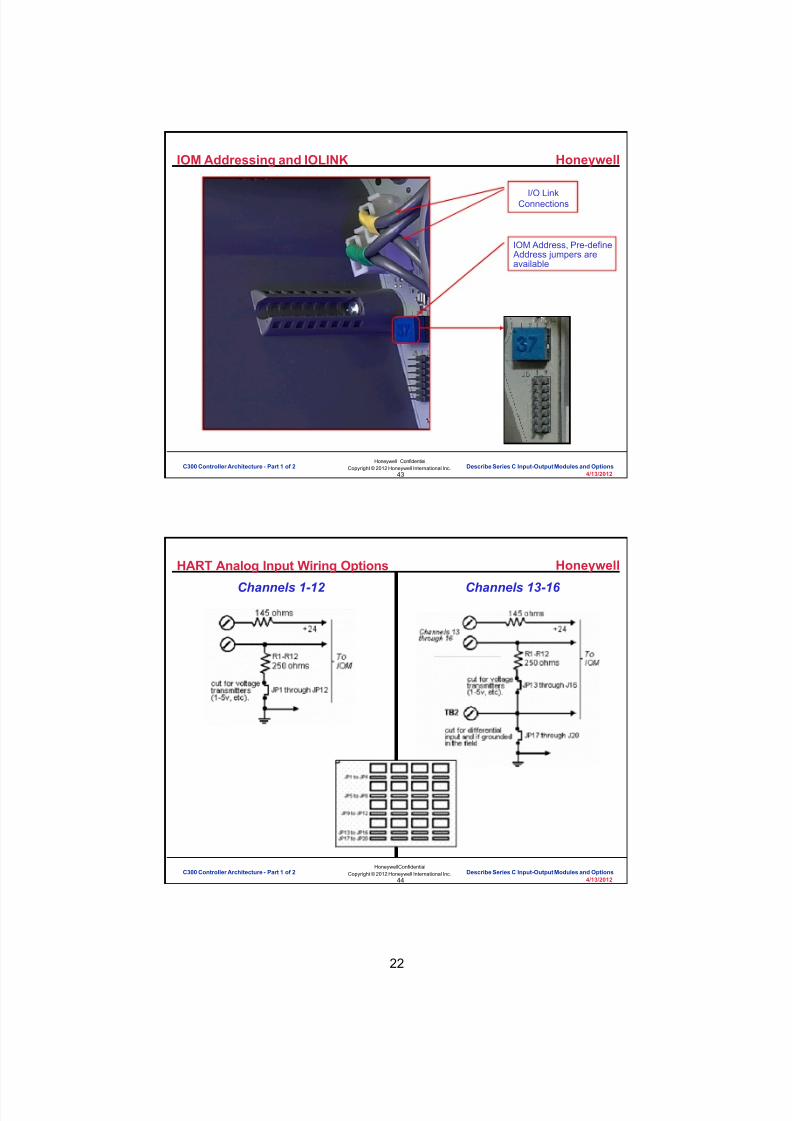
8/9/2019 Student Course Book- Automation
http://slidepdf.com/reader/full/student-course-book-automation 54/1165
22
Honeywell
Honeywell ConfidentialCopyright © 2012 Honeywell International Inc.
4/13/201243
IOM Addressing and IOLINK
I/O LinkConnections
IOM Address, Pre-define Address jumpers areavailable
C300 Controller Architecture - Part 1 of 2 Describe Series C Input-Output Modules and Options
Honeywell
Honeywell ConfidentialCopyright © 2012 Honeywell International Inc.
4/13/201244
HART Analog Input Wiring Options
Channels 1-12 Channels 13-16
C300 Controller Architecture - Part 1 of 2 Describe Series C Input-Output Modules and Options

8/9/2019 Student Course Book- Automation
http://slidepdf.com/reader/full/student-course-book-automation 55/1165
23
Honeywell
Honeywell ConfidentialCopyright © 2012 Honeywell International Inc.
4/13/201245
HART Analog Input –Redundant
ModuleFuse
I/O LinkConnections
I/O Link Address
Analog InputI/O Moduleprimary andredundant
C300 Controller Architecture - Part 1 of 2 Describe Series C Input-Output Modules and Options
Honeywell
Honeywell ConfidentialCopyright © 2012 Honeywell International Inc.
4/13/201246
HART Analog Input – Detail Displays
C300 Controller Architecture - Part 1 of 2 Describe Series C Input-Output Modules and Options

8/9/2019 Student Course Book- Automation
http://slidepdf.com/reader/full/student-course-book-automation 56/1165
24
Honeywell
Honeywell ConfidentialCopyright © 2012 Honeywell International Inc.
4/13/201247
HART Analog Output
• 16 Analog Channels
• Supports Integrated HARTCommunications
• Optionally Redundant
• 250ms Loop Latency whenused with Series C HLAI
• 4 configurable modems
C300 Controller Architecture - Part 1 of 2 Describe Series C Input-Output Modules and Options
Honeywell
Honeywell ConfidentialCopyright © 2012 Honeywell International Inc.
4/13/201248
HART Analog Output
CalibrationVoltage
Reference
Analog OutputI/O Module
I/O Link Address
I/O LinkConnections
C300 Controller Architecture - Part 1 of 2 Describe Series C Input-Output Modules and Options

8/9/2019 Student Course Book- Automation
http://slidepdf.com/reader/full/student-course-book-automation 57/1165
25
Honeywell
Honeywell ConfidentialCopyright © 2012 Honeywell International Inc.
4/13/201249
HART Analog Output –Detail Displays
C300 Controller Architecture - Part 1 of 2 Describe Series C Input-Output Modules and Options
Honeywell
Honeywell ConfidentialCopyright © 2012 Honeywell International Inc.
4/13/201250
Non-HART Series C IO Modules
• Non-HART versions of both the AI and AO
• These modules use the AI-HL and AO blocktemplates
• IO Unit Consumption remains the same asthe HART AI and HART AO
IOM ModelNames IOM Block Name Description Number of
Channels
Cx-PAIX01 AI-HL High Level Analog Input 16
Cx-PAOX01 AO Analog Output 16
C300 Controller Architecture - Part 1 of 2 Describe Series C Input-Output Modules and Options

8/9/2019 Student Course Book- Automation
http://slidepdf.com/reader/full/student-course-book-automation 58/1165
26
Honeywell
Honeywell ConfidentialCopyright © 2012 Honeywell International Inc.
4/13/201251
New Non-HART Series C IO Modules (R311.2 on)
• These Non-HART versions of both the AI and AO
contain no Hart functionality and are different from theCC-PAIX01 and CC-PAOX01
• They use different IOTAs:• AI IOTA – CC-TAIN01, CC-TAIN11 (red)• AO IOTA – CC-TAON01, CC-TAON11 (red)
• These modules use the AI-HL and AO block templates
• IO Unit Consumption remains the same asthe HART AI and HART AO
IOM ModelNames IOM Block Name Description Number of
Channels
CC-PAIN01 AI-HL High Level Analog Input 16
CC-PAON01 AO Analog Output 16
C300 Controller Architecture - Part 1 of 2 Describe Series C Input-Output Modules and Options
Honeywell
Honeywell ConfidentialCopyright © 2012 Honeywell International Inc.
4/13/201252
Low Level Inputs
• 64 Channel Low Level Multiplexer Analog Input – Thermocouple (T/C) and RTD
• Uses only the New Solid State FTAs – No plans to support the FTAs requiring the Power Adapter
• With the new Solid State FTAs: – OTD before propagation of PV every 1 sec – Does not require Power Adapter FTA – Can be used with existing UCN/xPM installations
• With the existing FTAs: – OTD propagates every 30 sec
• FTAs will require standard FTA Channel and cannot be mounted on
IOTA Carrier
C300 Controller Architecture - Part 1 of 2 Describe Series C Input-Output Modules and Options

8/9/2019 Student Course Book- Automation
http://slidepdf.com/reader/full/student-course-book-automation 59/1165
27
Honeywell
Honeywell ConfidentialCopyright © 2012 Honeywell International Inc.
4/13/201253
LLMUX SolutionsStandard Solution
51304465-xxxIntern alCabi net Cable
LL IN-CABINET CONFIGURATION
B-Size
LLMUX ModelsMU/MC-TAMT04MU/MC-TAMR04MU/MC-TAMT14
FTA Assemblies must beinstalled in a cabinet.
CU/CC-TAIM01
VL/BS
LL TCMUX IOTA
Power
Status
PMIOLLMUX
CC-PAIM01C
6 C o n d u c t o r C a b l e H e a d
New FTAs Only (no Power Adapter)
Max. Length1000 ft.
C300 Controller Architecture - Part 1 of 2 Describe Series C Input-Output Modules and Options
Honeywell
Honeywell ConfidentialCopyright © 2012 Honeywell International Inc.
4/13/201254
Digital Input
• 32 Channels• Two (2) Physical IOM Types
1. 24VDC2. 100VAC/120VAC/125VDC/240VAC
• Three (3) Physical IOTA Types1. 24VDC2. 120VAC/125VDC3. 240VAC
• Optionally Redundant• 100ms Loop Latency
C300 Controller Architecture - Part 1 of 2 Describe Series C Input-Output Modules and Options

8/9/2019 Student Course Book- Automation
http://slidepdf.com/reader/full/student-course-book-automation 60/1165
28
Honeywell
Honeywell ConfidentialCopyright © 2012 Honeywell International Inc.
4/13/201255
Digital Input, contd.
I/O Link
Connections
Digital InputI/O Module
I/O Link Address
C300 Controller Architecture - Part 1 of 2 Describe Series C Input-Output Modules and Options
Honeywell
Honeywell ConfidentialCopyright © 2012 Honeywell International Inc.
4/13/201256
Digital Input –Detail Displays
C300 Controller Architecture - Part 1 of 2 Describe Series C Input-Output Modules and Options
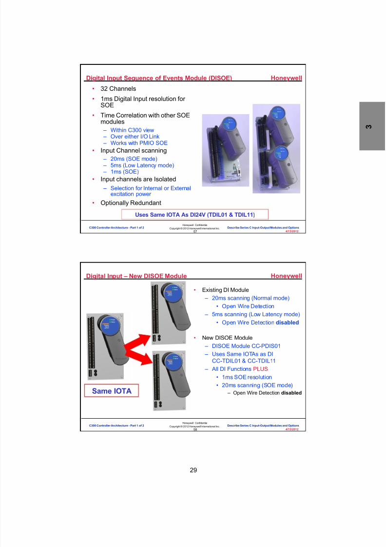
8/9/2019 Student Course Book- Automation
http://slidepdf.com/reader/full/student-course-book-automation 61/1165
29
Honeywell
Honeywell ConfidentialCopyright © 2012 Honeywell International Inc.
4/13/201257
Digital Input Sequence of Events Module (DISOE)
• 32 Channels
• 1ms Digital Input resolution forSOE
• Time Correlation with other SOEmodules – Within C300 view – Over either I/O Link – Works with PMIO SOE
• Input Channel scanning – 20ms (SOE mode) – 5ms (Low Latency mode) – 1ms (SOE)
• Input channels are Isolated – Selection for Internal or External
excitation power
• Optionally Redundant
Uses Same IOTA As DI24V (TDIL01 & TDIL11)
C300 Controller Architecture - Part 1 of 2 Describe Series C Input-Output Modules and Options
Honeywell
Honeywell ConfidentialCopyright © 2012 Honeywell International Inc.
4/13/201258
Digital Input – New DISOE Module
• Existing DI Module – 20ms scanning (Normal mode)
• Open Wire Detection – 5ms scanning (Low Latency mode)
• Open Wire Detection disabled
• New DISOE Module – DISOE Module CC-PDIS01 – Uses Same IOTAs as DI
CC-TDIL01 & CC-TDIL11 – All DI Functions PLUS
• 1ms SOE resolution• 20ms scanning (SOE mode)
– Open Wire Detection disabledSame IOTA
C300 Controller Architecture - Part 1 of 2 Describe Series C Input-Output Modules and Options

8/9/2019 Student Course Book- Automation
http://slidepdf.com/reader/full/student-course-book-automation 62/1165
30
Honeywell
Honeywell ConfidentialCopyright © 2012 Honeywell International Inc.
4/13/201259
24V Digital Input IOTA for DI & DISOE
I/O Link
Connections
Digital InputI/O Module
I/O Link Address
DISOE usesthe same
IOTAs as DI(CC-TDIL01 &
CC-TDIL11)
CC-TDIL01
C300 Controller Architecture - Part 1 of 2 Describe Series C Input-Output Modules and Options
Honeywell
Honeywell ConfidentialCopyright © 2012 Honeywell International Inc.
4/13/201260
Digital Input – Detail Displays
C300 Controller Architecture - Part 1 of 2 Describe Series C Input-Output Modules and Options

8/9/2019 Student Course Book- Automation
http://slidepdf.com/reader/full/student-course-book-automation 63/1165
31
Honeywell
Honeywell ConfidentialCopyright © 2012 Honeywell International Inc.
4/13/201261
Digital Output
• 32 Channels• Same IOM used for 24VDC or
High Voltage Output• IOTA Types
– Redundant and Non-redundant – 24VDC Bussed Output – High Voltage Relay Output
• 100VAC / 120VAC / 240VAC /125VDC / 48VDC
• Utilizes Relay Extension Board
• Optionally Redundant• 100ms Loop Latency
C300 Controller Architecture - Part 1 of 2 Describe Series C Input-Output Modules and Options
Honeywell
Honeywell ConfidentialCopyright © 2012 Honeywell International Inc.
4/13/201262
Digital Output
I/O LinkConnections
Digital OutputI/O Module
I/O Link Address
C300 Controller Architecture - Part 1 of 2 Describe Series C Input-Output Modules and Options
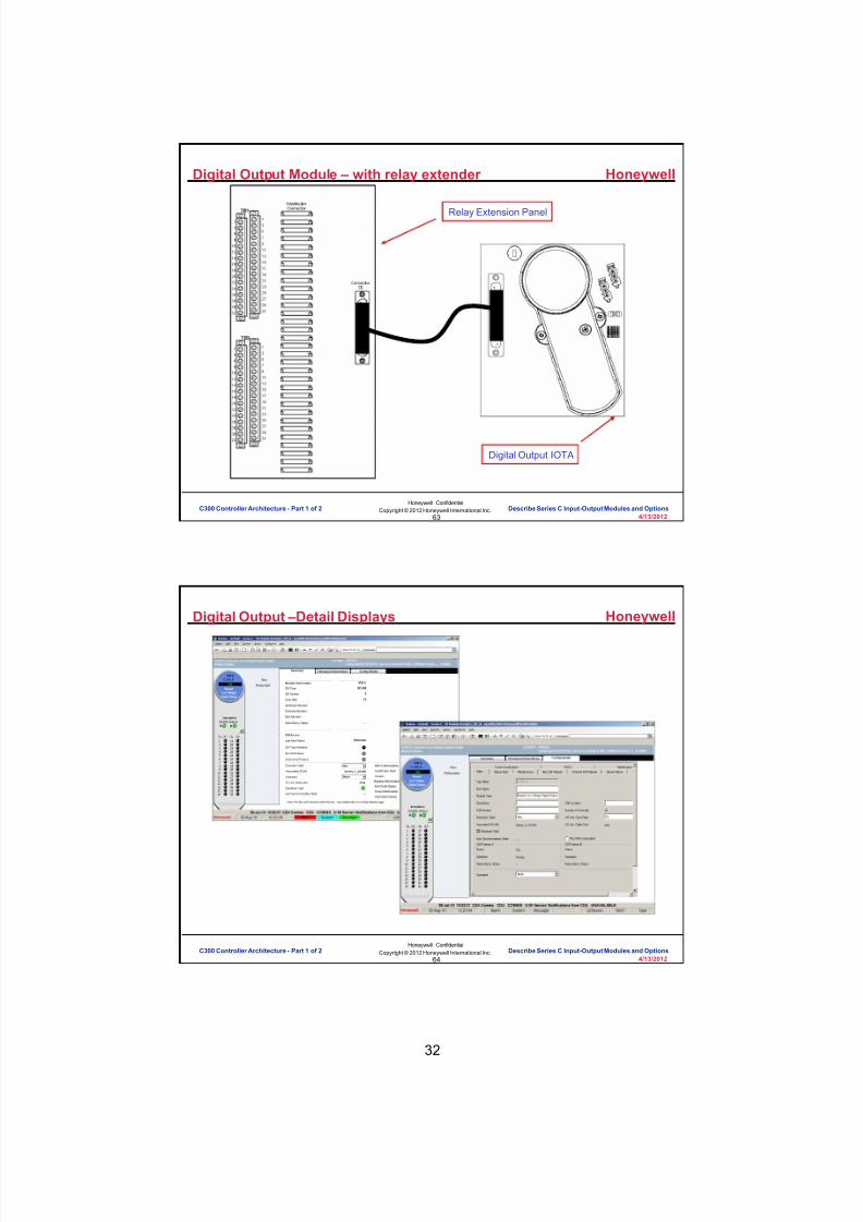
8/9/2019 Student Course Book- Automation
http://slidepdf.com/reader/full/student-course-book-automation 64/1165
32
Honeywell
Honeywell ConfidentialCopyright © 2012 Honeywell International Inc.
4/13/201263
Digital Output Module – with relay extender
Relay Extension Panel
Digital Output IOTA
C300 Controller Architecture - Part 1 of 2 Describe Series C Input-Output Modules and Options
Honeywell
Honeywell ConfidentialCopyright © 2012 Honeywell International Inc.
4/13/201264
Digital Output –Detail Displays
C300 Controller Architecture - Part 1 of 2 Describe Series C Input-Output Modules and Options

8/9/2019 Student Course Book- Automation
http://slidepdf.com/reader/full/student-course-book-automation 65/1165
33
Honeywell
Honeywell ConfidentialCopyright © 2012 Honeywell International Inc.
4/13/201265
Series C I/O in Hazardous Areas
• Honeywell worked with MTL to manufacturean IOTA for use when wiring into hazardouslocations (C1D1 / Zone 1).
• The IOTA will be larger than a standardIOTA (approximately 9” wide)
• 1-, 2- and 4-channel isolators are available
C300 Controller Architecture - Part 1 of 2 Describe Series C Input-Output Modules and Options
Honeywell
Honeywell ConfidentialCopyright © 2012 Honeywell International Inc.
4/13/201266
Series C I/O in Hazardous Areas, contd.
Non-RedundantIOTA + IOM
RedundantIOTA + IOM
6.00”
StandardIOTA Footprint
I/SIOTA Footprint
C300 Controller Architecture - Part 1 of 2 Describe Series C Input-Output Modules and Options

8/9/2019 Student Course Book- Automation
http://slidepdf.com/reader/full/student-course-book-automation 66/1165
34
Honeywell
Honeywell ConfidentialCopyright © 2012 Honeywell International Inc.
4/13/201267
Series C I/O in Hazardous Areas
abinet Layout – Wide hannel
• Supports mixture of IS and generalpurpose signals within same cabinet
• Cables are segregated using hazardous-area trunking
• High vertical packing density
C300 Controller Architecture - Part 1 of 2 Describe Series C Input-Output Modules and Options
Honeywell
Honeywell ConfidentialCopyright © 2012 Honeywell International Inc.
4/13/201268
Process Manager I/O
• No separate IOLIM needed, connects directly to IOLink• PM I/O includes AI, AO, DI, DO, RTD, T/C, DI SOE
• PM I/O can be redundant
– HLAI, HLAIHART, STIM, AO, AO16HART, DI, DISOE, DO
– NOT: LLAI, LLMUX, and RHMUX
• FTA for I/O
• Remote I/O using Fiber Optic
PM I/O
Direct connectionto C300 IOLINK
Direct connectionto C300 IOLINK
C300 Controller Architecture - Part 1 of 2 Describe Series C Input-Output Modules and Options
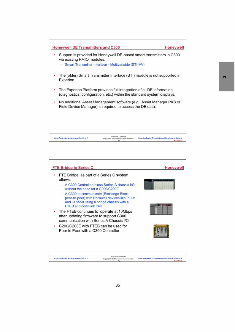
8/9/2019 Student Course Book- Automation
http://slidepdf.com/reader/full/student-course-book-automation 67/1165
35
Honeywell
Honeywell ConfidentialCopyright © 2012 Honeywell International Inc.
4/13/201269
Honeywell DE Transmitters and C300
• Support is provided for Honeywell DE-based smart transmitters in C300via existing PMIO modules: – Smart Transmitter Interface – Multivariable (STI-MV)
• The (older) Smart Transmitter Interface (STI) module is not supported inExperion
• The Experion Platform provides full integration of all DE information(diagnostics, configuration, etc.) within the standard system displays.
• No additional Asset Management software (e.g., Asset Manager PKS orField Device Manager) is required to access the DE data.
C300 Controller Architecture - Part 1 of 2 Describe Series C Input-Output Modules and Options
Honeywell
Honeywell ConfidentialCopyright © 2012 Honeywell International Inc.
4/13/201270
FTE Bridge in Series C
• FTE Bridge, as part of a Series C systemallows: – A C300 Controller to use Series A chassis I/O
without the need for a C200/C200E – A C300 to communicate (Exchange Block
peer-to-peer) with Rockwell devices like PLC5and CL5550 using a bridge chassis with aFTEB and downlink CNI
• The FTEB continues to operate at 10Mbpsafter updating firmware to support C300communication with Series A Chassis I/O
• C200/C200E with FTEB can be used forPeer to Peer with a C300 Controller
C300 Controller Architecture - Part 1 of 2 Describe Series C Input-Output Modules and Options

8/9/2019 Student Course Book- Automation
http://slidepdf.com/reader/full/student-course-book-automation 68/1165
36
Honeywell
Honeywell ConfidentialCopyright © 2012 Honeywell International Inc.
4/13/201271
Which of the following I/O’s are available in
a Series C type?
Question 3: Series C I/O
Incorrect. The I/O's available in aSeries C type are DI, DO, HLAI,
HLAO and LL Inputs.
Click anywhere to continue.
Correct! The I/O's available in aSeries C type are DI, DO, HLAI,
HLAO and LL Inputs.
Click anywhere to continue.
Incorrect. The I/O's available in aSeries C type are DI, DO, HLAI,
HLAO and LL Inputs.
Click anywhere to continue.
Incorrect. The I/O's available in aSeries C type are DI, DO, HLAI,
HLAO and LL Inputs.
Click anywhere to continue.
Correct - Click anywhere to continueIncorrect - Click anywhere to continueYou answered this correctly!
Your answer:The correct answer is:
You did not answer this question completelyYou must answer the question before
continuing
Submit Clear
A) HLAI, HLAO, Profibus I/O, LL Inputs
B) DI, DISOE, DO, HLAI, HLAO, LL Inputs
C) HLAI, HLAO, LL Inputs, Serial Interface
D) Serial Interface, DeviceNet, Pulse Input, HLAI
C300 Controller Architecture - Part 1 of 2 Describe Series C Input-Output Modules and Options
Honeywell
Honeywell ConfidentialCopyright © 2012 Honeywell International Inc.
4/13/201272
Which of the following scenarios are available for a FTEB to publish I/Odata to a C300?
Question 4: FTEB in Series C
Incorrect. The valid scenario for FTEB to publish I/Odata to C300 is " FTEB in a non redundant I/O chassisconnected to C300 via Control Firewall."
Click anywhere to continue.
Correct! The valid scenario for FTEB to publish I/Odata to C300 is " FTEB in a non redundant I/O chassisconnected to C300 via Control Firewall."
Click anywhere to continue.
Incorrect. The valid scenario for FTEB to publish I/Odata to C300 is " FTEB in a non redundant I/O chassisconnected to C300 via Control Firewall."
Click anywhere to continue.
Correct - Click anywhere to continueIncorrect - Click anywhere to continueYou answered this correctly!
Your answer: The correct answer is:
You did not answer this question completelyYou must answer the question beforecontinuing
Submit Clear
A) FTEB in redundant chassis connected to C300
B) FTEB in a non-redundant chassis connected toC300 via Control Firewall
C) FTEB in a non-redundant chassis connected toC300 via L1 or L2 switch
C300 Controller Architecture - Part 1 of 2 Describe Series C Input-Output Modules and Options

8/9/2019 Student Course Book- Automation
http://slidepdf.com/reader/full/student-course-book-automation 69/1165

8/9/2019 Student Course Book- Automation
http://slidepdf.com/reader/full/student-course-book-automation 70/1165
38
Honeywell
Honeywell ConfidentialCopyright © 2012 Honeywell International Inc.
4/13/201275
Conclusion
Describe Series C Input/Output Modules and Options
CompletionCertificate
Proceed to the next lesson in your course material.
C300 Controller Architecture - Part 1 of 2 Describe Series C Input-Output Modules and Options
Honeywell
Honeywell ConfidentialCopyright © 2012 Honeywell International Inc.
4/13/201276
This page intentionally left blank
C300 Controller Architecture - Part 1 of 2 Describe Series C Input-Output Modules and Options
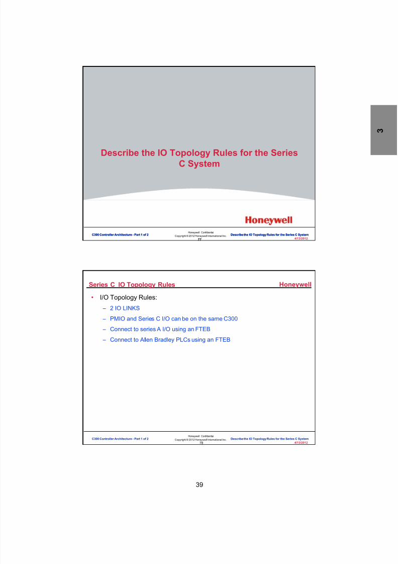
8/9/2019 Student Course Book- Automation
http://slidepdf.com/reader/full/student-course-book-automation 71/1165
39
77
Honeywell ConfidentialCopyright © 2012 Honeywell International Inc.
4/13/2012
Describe the IO Topology Rules for the SeriesC System
C300 Controller Architecture - Part 1 of 2 Describe the IO Topology Rules for the Series C SystemC300 Controller Architecture - Part 1 of 2 Describe the IO Topology Rules for the Series C System
Honeywell
Honeywell ConfidentialCopyright © 2012 Honeywell International Inc.
4/13/201278
Series C IO Topology Rules
• I/O Topology Rules: – 2 IO LINKS
– PMIO and Series C I/O can be on the same C300
– Connect to series A I/O using an FTEB
– Connect to Allen Bradley PLCs using an FTEB
C300 Controller Architecture - Part 1 of 2 Describe the IO Topology Rules for the Series C System

8/9/2019 Student Course Book- Automation
http://slidepdf.com/reader/full/student-course-book-automation 72/1165
40
Honeywell
Honeywell ConfidentialCopyright © 2012 Honeywell International Inc.
4/13/201279
C300 Topology Rules – IO Capacity
A C300 can support a maximum of 64 IO Units (IOU).
Series C IO and PM IO count as 1 IOU each.
Series C IO and PMIO are connected to C300 usingIO LINKS.
Series A I/O also consume IOUs, shown later.
C300 Controller Architecture - Part 1 of 2 Describe the IO Topology Rules for the Series C System
Honeywell
Honeywell ConfidentialCopyright © 2012 Honeywell International Inc.
4/13/201280
C300 Topology Rules – IOLINK Capacity
Each IO Link can support a maximum of 40 IOUs.
A C300 controller supports 2 IO LINKs.
An IO LINK can be configured for either Series C IO(at 750 kb link speed) or PMIO (at 375 kb link speed).
An IO LINK cannot support both Series C IO andPMIO on the same link.
C300 Controller Architecture - Part 1 of 2 Describe the IO Topology Rules for the Series C System

8/9/2019 Student Course Book- Automation
http://slidepdf.com/reader/full/student-course-book-automation 73/1165
41
Honeywell
Honeywell ConfidentialCopyright © 2012 Honeywell International Inc.
4/13/201281
Series C IO and PMIO Mix
#1: Series C I/OTOTAL 64 IOUs
Link 1750 kbps
Link 2750 kbps
40 PRISeries C IOMs40 RED
Series C IOMs
24 PRISeries C IOMs
24 REDSeries C IOMs
#2: PMIOTOTAL 64 IOUs
Link 1375 kbps
Link 2375 kbps
24 PRIPM - IOPs
24 REDPM - IOPs
40 PRIPM - IOPs
40 REDPM - IOPs
#3: Series C +PMIOTOTAL 64 IOUs
Link 1750 kbps
Link 2375 kbps
40 PRISeries C IOMs40 RED
Series C IOMs
24 PRIPM - IOPs
24 REDPM - IOPs
#4: Series C +PMIOTOTAL 64 IOUs
Link 1375 kbps
Link 2750 kbps
40 PRIPM - IOPs
40 REDPM - IOPs
24 PRISeries C IOMs
24 REDSeries C IOMs
C300 Controller Architecture - Part 1 of 2 Describe the IO Topology Rules for the Series C System
Honeywell
Honeywell ConfidentialCopyright © 2012 Honeywell International Inc.
4/13/201282
C300 Topology Rules – FTEB Connections to CF9
A C300 can support up to 7 FTEBs for interfacing with
supported Chassis I/O or AB PLC interface.FTEBs must be connected to the same Control Firewallas the C300.
This limits the FTEBs to 6 per redundant C300controller.
C300 Controller Architecture - Part 1 of 2 Describe the IO Topology Rules for the Series C System

8/9/2019 Student Course Book- Automation
http://slidepdf.com/reader/full/student-course-book-automation 74/1165
42
Honeywell
Honeywell ConfidentialCopyright © 2012 Honeywell International Inc.
4/13/201283
C300 Topology Rules – Series A IOU Capacity
Each FTEB used to connect Series A IO can support up to 16IOUs. The IOU count per module is:
The FTEB used for Series A cannot be in a redundantconfiguration.
Serial
Interface 8 per FTA DeviceNet Interface 4ProfibusInterface 4 Pulse Input 1
C300 Controller Architecture - Part 1 of 2 Describe the IO Topology Rules for the Series C System
Honeywell
Honeywell ConfidentialCopyright © 2012 Honeywell International Inc.
4/13/201284
C300Capacity 3 – MIX #3Link 1750 kbps
Link 2375 kbps
24 PRIPM-IOPs24 REDPM-IOPs
24 PRISeries C IOMs
24 REDSeries C IOMs
16 Series A IOUnits w/FTEBFTE
#5: Series C + PMIO + Series ATOTAL 64 IOUs
C300 Controller I/O Link Configurations
C300 Controller Architecture - Part 1 of 2 Describe the IO Topology Rules for the Series C System

8/9/2019 Student Course Book- Automation
http://slidepdf.com/reader/full/student-course-book-automation 75/1165
43
Honeywell
Honeywell ConfidentialCopyright © 2012 Honeywell International Inc.
4/13/201285
C300 Topology Rules – FTEB Limitations
Important limitations:
An FTEB connected chassis can allow connectionsto only 1 C300 controller.
You cannot have any other C200/C200E, IO or CNIdownlink modules in the FTEB chassis to connect toother IO chassis.
C300 Controller Architecture - Part 1 of 2 Describe the IO Topology Rules for the Series C System
Honeywell
Honeywell ConfidentialCopyright © 2012 Honeywell International Inc.
4/13/201286
C300 Topology Rules – FTEB I/F Capacity
CNI, ENET orDHRIO only
FTEBs can be used to connect AB PLCs for Peer to
Peer, using Exchange Blocks. No IOUs consumed. A maximum of 32 exchange blocks, and a maximumof 8 PLCs can be connected.
The interface uses Control Net to the AB PLCs andallows only the CNI, ENET or DHRIO.
C300 Controller Architecture - Part 1 of 2 Describe the IO Topology Rules for the Series C System

8/9/2019 Student Course Book- Automation
http://slidepdf.com/reader/full/student-course-book-automation 76/1165
44
Honeywell
Honeywell ConfidentialCopyright © 2012 Honeywell International Inc.
4/13/201287
C300 Topology Rules – Series C FIM Usage
A Series C FIM can be used with or without the C300.
A FIM needs to connect to a C300 if a combinedcontrol strategy is needed.
A FIM4 counts as 4 IOUs; A FIM8 counts as 8 IOUs
A C300 can support 15 FIM4s, or up to 8 FIM8s A mix of FIM4s & FIM8s is supported as long as thetotal number of H1 links does not exceed 64
C300 Controller Architecture - Part 1 of 2 Describe the IO Topology Rules for the Series C System
Honeywell
Honeywell ConfidentialCopyright © 2012 Honeywell International Inc.
4/13/201288
C300 Topology Rules – Series C FIM Capacity
An Experion Server can support up to 125 FIMs.
A FIM supports 4 or 8 H1 links, with 16 devices perlink.
An Experion Server can support up to 12000FieldBus devices!
C300 Controller Architecture - Part 1 of 2 Describe the IO Topology Rules for the Series C System

8/9/2019 Student Course Book- Automation
http://slidepdf.com/reader/full/student-course-book-automation 77/1165
45
Honeywell
Honeywell ConfidentialCopyright © 2012 Honeywell International Inc.
4/13/201289
C300 Topology Rules – PGM Connection and Capacity
It is not necessary to connect a PGM to the sameCF9 as the C300 (but is a good practice)
A C300 can support 2 PGMs.
A PGM supports two ProfiBus links
Each ProfiBus Link supports up to 124 devicesEach device supports up to 16 I/O modules
IOUs consumed by a PGM must be calculated(# Digital IO Points / 384) + (# Analog IO Points / 24)
C300 Controller Architecture - Part 1 of 2 Describe the IO Topology Rules for the Series C System
Honeywell
Honeywell ConfidentialCopyright © 2012 Honeywell International Inc.
4/13/201290
Question 1: IO Topology Rules
Correct! Series C, PM and Series A IO on the same IOLINKis not true for a Series C IO Topology. An IOLINK cannotsupport both Series C IO and PMIO on the same link. AnFTEB connected to the same Control Firewall as the C300
controller can publish Series A IO data to the C300.
Click anywhere to continue.
Correct - Click anywhere to continueIncorrect - Click anywhere to continueYou answered this correctly!
Your answer: The correct answer is:
You did not answer this question completelyYou must answer the question beforecontinuing
Submit Clear
Which of the following statements is not true for Series C IO TopologyRules?
Incorrect. Series C, PM and Series A IO on the same
IOLINK is not true for a Series C IO Topology. An IOLINKcannot support both Series C IO and PMIO on the samelink. An FTEB connected to the same Control Firewall asthe C300 controller can publish Series A IO data to the
C300.
Click anywhere to continue.
A) Series C, PM and Series C A IO on the sameIO Link
B) Series C and PM IO cannot be on the same IO Link
C) FTEB connected chassis can allow connections toonly 1 C300 controller
D) Each FTEB used to connect Series A IO can supportup to 16 IOUs
C300 Controller Architecture - Part 1 of 2 Describe the IO Topology Rules for the Series C System

8/9/2019 Student Course Book- Automation
http://slidepdf.com/reader/full/student-course-book-automation 78/1165
46
Honeywell
Honeywell ConfidentialCopyright © 2012 Honeywell International Inc.
4/13/201291
Question 2: Topology Rules
Correct - Click anywhere to continueIncorrect - Click anywhere to continueYou answered this correctly!
Your answer:The correct answer is:
You did not answer this question completelyYou must answer the question beforecontinuing
Submit Clear
No. The correct statement is "No C300 controllers arerequired, only 24 Series C FIM Modules". Since the
project requires only Fieldbus control strategy the C300controller is not required. Each FIM Module has 4 FF links
and each link supports 16 FF devices. Hence 1 FIMmodule can support a maximum of 64 (16*4) FF dev ices.
Hence only 24 (1500/64) Series C FIM Modules arerequired.
Click anywhere to continue.
Yes! The correct statement is "No C300 controllers arerequired, only 24 Series C FIM Modules". Since the
project requires only Fieldbus control strategy the C300controller is not required. Each FIM Module has 4 FF links
and each link supports 16 FF devices. Hence 1 FIMmodule can support a maximum of 64 (16*4) FF dev ices.
Hence only 24 (1500/64) Series C FIM Modules arerequired.
Click anywhere to continue.
A project is required to use Fieldbus only control strategy for 1500 FF
devices. How many C300 controllers are required? A) 2 C300 Controllers + 24 FIM Modules
B) 1 C300 Controller + 48 FIM Modules
C) No C300 Controllers are required, only 24 Series CFIM Modules
C300 Controller Architecture - Part 1 of 2 Describe the IO Topology Rules for the Series C System
Honeywell
Honeywell ConfidentialCopyright © 2012 Honeywell International Inc.
4/13/201292
Question 3: Topology Rules
Incorrect. All of the above statements are correctfor FTEBs used in the Series C topology.
Click anywhere to continue.
Incorrect. All of the above statements are correctfor FTEBs used in the Series C topology.
Click anywhere to continue.
Incorrect. All of the above statements are correctfor FTEBs used in the Series C topology.
Click anywhere to continue.
Correct! All of the above statements are correct forFTEBs used in the Series C topology.
Click anywhere to continue.
Correct - Click anywhere to continueIncorrect - Click anywhere to continueYou answered this correctly!
Your answer: The correct answer is:
You did not answer this question completelyYou must answer the question beforecontinuing
Submit Clear
FTEBs can be used in the Series C topology under specific scenarios.Which of these configurations is valid?
A) FTEB connected to AB PLC via Downlink CNI
B) FTEBs must be connected to the same ControlFirewall as the C300
C) An FTEB connected chassis can allow connectionsto only 1 C300 controller
D) All of the above
C300 Controller Architecture - Part 1 of 2 Describe the IO Topology Rules for the Series C System

8/9/2019 Student Course Book- Automation
http://slidepdf.com/reader/full/student-course-book-automation 79/1165
47
Honeywell
Honeywell ConfidentialCopyright © 2012 Honeywell International Inc.
4/13/201293
Summary• There are 2 IO LINKS per C300
– Mix and match of Series C I/O and PMIO is an option – Same IO LINK cannot support both Series C and PM IO
• A C300 can support a maximum of 64 IO Units (IOU). – Each IO Link can support a maximum of 40 IOUs – Each FTEB used to connect Series A IO can support up to 16 IOUs
• A C300 can support up to 7 FTEBs – FTEBs must be connected to the same Control Firewall as the C300 – FTEBs interface with Series A I/O or AB PLC interface – FTEBs cannot be in a redundant configuration
• A Series C FIM can be used with or without the C300.
• A C300 can support 15 FIMs.
• An Experion Server can support up to 125 FIMs.
• A C300 can support 2 PGMs.
C300 Controller Architecture - Part 1 of 2 Describe the IO Topology Rules for the Series C System
Honeywell
Honeywell ConfidentialCopyright © 2012 Honeywell International Inc.
4/13/201294
Conclusion
Describe the I/O Topology Rules for the Series C System
CompletionCertificate
Proceed to the next lesson in your course material
C300 Controller Architecture - Part 1 of 2 Describe the IO Topology Rules for the Series C System

8/9/2019 Student Course Book- Automation
http://slidepdf.com/reader/full/student-course-book-automation 80/1165
Copyright © 201 2 Honeywell International Inc.
HPS Automation College written permission required to distributeHoneywell Confidential and Proprietary
This page was intentionally left blank.

8/9/2019 Student Course Book- Automation
http://slidepdf.com/reader/full/student-course-book-automation 81/1165
4/13/2012 Copyright © 2012 Honeywell International Inc. 1
HPS Automation College written permission required to distributeHoneywell Confidential and Proprietary
Topic: C300 Controller Architecture - Part 1 of 2
Contents
Verify Series C Hardware Connections ................................................................................................. 3

8/9/2019 Student Course Book- Automation
http://slidepdf.com/reader/full/student-course-book-automation 82/1165
2 Copyright © 2012 Honeywell International Inc. 4/13/2012
HPS Automation College written permission required to distributeHoneywell Confidential and Proprietary
This page was intentionally left blank.

8/9/2019 Student Course Book- Automation
http://slidepdf.com/reader/full/student-course-book-automation 83/1165
C300 Controller Architecture - Part 1 of 2
Verify Series C Hardware Connections
4/13/2012 Copyright © 2012 Honeywell International Inc. 3
HPS Automation College written permission required to distributeHoneywell Confidential and Proprietary
Verify Series C Hardware Connections
Introduction
The following Lab will allow you to become more familiar with the Series C Hardware.
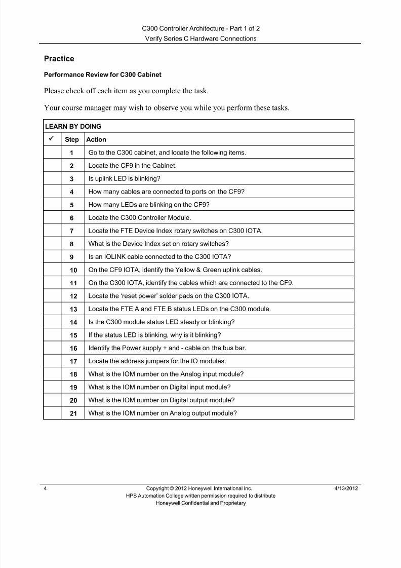
8/9/2019 Student Course Book- Automation
http://slidepdf.com/reader/full/student-course-book-automation 84/1165
C300 Controller Architecture - Part 1 of 2
Verify Series C Hardware Connections
4 Copyright © 2012 Honeywell International Inc. 4/13/2012
HPS Automation College written permission required to distributeHoneywell Confidential and Proprietary
Practice
Performance Review for C300 Cabinet
Please check off each item as you complete the task.
Your course manager may wish to observe you while you perform these tasks.
LEARN BY DOING
Step Action
1 Go to the C300 cabinet, and locate the following items.
2 Locate the CF9 in the Cabinet.
3 Is uplink LED is blinking?
4 How many cables are connected to ports on the CF9?
5 How many LEDs are blinking on the CF9?
6 Locate the C300 Controller Module.
7 Locate the FTE Device Index rotary switches on C300 IOTA.
8 What is the Device Index set on rotary switches?
9 Is an IOLINK cable connected to the C300 IOTA?
10 On the CF9 IOTA, identify the Yellow & Green uplink cables.
11 On the C300 IOTA, identify the cables which are connected to the CF9.
12 Locate the ‘reset power’ solder pads on the C300 IOTA.13 Locate the FTE A and FTE B status LEDs on the C300 module.
14 Is the C300 module status LED steady or blinking?
15 If the status LED is blinking, why is it blinking?
16 Identify the Power supply + and - cable on the bus bar.
17 Locate the address jumpers for the IO modules.
18 What is the IOM number on the Analog input module?
19 What is the IOM number on Digital input module?
20 What is the IOM number on Digital output module?
21 What is the IOM number on Analog output module?

8/9/2019 Student Course Book- Automation
http://slidepdf.com/reader/full/student-course-book-automation 85/1165
1
1
Honeywell ConfidentialCopyright © 2012 Honeywell International Inc.
4/30/2012
Describe the Functionality of Control Builder
Control Builder Introduction Describe the Functionality of Control BuilderControl Builder Introduction Describe the Functionality of Control Builder
Honeywell
Honeywell ConfidentialCopyright © 2012 Honeywell International Inc.
4/30/20122
Introduction
• In this lesson you will learn about thepurpose and use of the Control Builderapplication.
• At the conclusion of this lesson, you willbe able to:
– Open and navigate Control Builder
– Identify the toolbar icons and functionality
– Explain the purpose of the tabs in thetree windows
– Describe the load functions availablefrom the Control Builder Project andMonitoring tabs
Control Builder Introduction Describe the Functionality of Control Builder

8/9/2019 Student Course Book- Automation
http://slidepdf.com/reader/full/student-course-book-automation 86/1165
2
Honeywell
Honeywell ConfidentialCopyright © 2012 Honeywell International Inc.
4/30/20123
Topics
• Starting Control Builder
• Control Builder Functions
• Control Builder Load Function
Control Builder Introduction Describe the Functionality of Control Builder
Honeywell
Honeywell ConfidentialCopyright © 2012 Honeywell International Inc.
4/30/20124
Start Control Builder
Click to openConfiguration Studio
Control Builder Introduction Describe the Functionality of Control Builder

8/9/2019 Student Course Book- Automation
http://slidepdf.com/reader/full/student-course-book-automation 87/1165
3
Honeywell
Honeywell ConfidentialCopyright © 2012 Honeywell International Inc.
4/30/20125
Start Control Builder, contd.
Select the server.Then, select the Connect button.
General rule:Select the System.Here we are selectingthe server.
Control Builder Introduction Describe the Functionality of Control Builder
Honeywell
Honeywell ConfidentialCopyright © 2012 Honeywell International Inc.
4/30/20126
• Configuration Studio login is not required for integrated accounts or Users addedto Experion Install time groups
• Experion Install time groups include following – Product Administrators – Local Engineers – Local Supervisors – Local Operators – Local Ack View Only Users – Local View Only Users
User accounts
Windows usercreated for
Windows login
Windows user is part ofExperion groups
Control Builder Introduction Describe the Functionality of Control Builder

8/9/2019 Student Course Book- Automation
http://slidepdf.com/reader/full/student-course-book-automation 88/1165
4
Honeywell
Honeywell ConfidentialCopyright © 2012 Honeywell International Inc.
4/30/20127
Start Control Builder, contd.
User Name: mngr Password: mngr1Domain: <Traditional Operator Security>
Change to
Click
Careful, this user & passwordmay not work at your site.In fact, you may not be requiredto enter user name & password.
A logon window will appear only
when you have logged on toWindows as a user who is not amember of a pre-definedExperion group
Control Builder Introduction Describe the Functionality of Control Builder
Honeywell
Honeywell ConfidentialCopyright © 2012 Honeywell International Inc.
4/30/20128
Start Control Builder, contd.
Select ControlStrategy
Server name
User name
Access level
This information is displayedonly if you connected to theServer, not the System.
Select Configure ProcessControl Strategies
Control Builder Introduction Describe the Functionality of Control Builder

8/9/2019 Student Course Book- Automation
http://slidepdf.com/reader/full/student-course-book-automation 89/1165
5
Honeywell
Honeywell ConfidentialCopyright © 2012 Honeywell International Inc.
4/30/20129
Topics
• Starting Control Builder
• Control Builder Functions
• Control Builder Load Function
Control Builder Introduction Describe the Functionality of Control Builder
Honeywell
Honeywell ConfidentialCopyright © 2012 Honeywell International Inc.
4/30/201210
Control Builder Toolbar
Not all toolbar icons will be availableuntil you open Control Builder items.
Control Builder Introduction Describe the Functionality of Control Builder

8/9/2019 Student Course Book- Automation
http://slidepdf.com/reader/full/student-course-book-automation 90/1165
6
Honeywell
Honeywell ConfidentialCopyright © 2012 Honeywell International Inc.
4/30/201211
Control Builder Toolbar, contd.
11 Display help information12 Point Selection Command13 Create a wire for connecting function
blocks14 Create a Parameter Connector 15 Assign Modules to a Control
Execution Environment (CEE)16 Module Containment17 Load selected items18 Upload selected items19 Substitute Names20 QVCS Manager 21 Toggle single item state22 SCM Navigation23 Fieldbus DD import24 View error log25 Change scale dimensions
1 2 3 4 5 6 7 8 9 10 11 12 13 14 15 16 17 18 19 20 21 22 23 24 25
1 Open Tree Window2 Close active Control Drawing
or Tree Window3 Move to the Left4 Move to the Right5 Save the active Control Drawing6 Delete the selected object7 Copy selection and place on
clipboard8 Paste clipboard contents9 Print selected pages of active
document10 Display program information
This is a good reference page,you may want to “flag” it.
Control Builder Introduction Describe the Functionality of Control Builder
Honeywell
Honeywell ConfidentialCopyright © 2012 Honeywell International Inc.
4/30/201212
Control Builder Status Line
Experion PKS server namecurrently running as primary
Security level
‘Primary’ when connected to ServerB‘Backup’ when connected to ServerA
(should always be Primary)
Shows ‘Sync’ when ERDBs onServerA and ServerB aresynchronized
Control Builder Introduction Describe the Functionality of Control Builder

8/9/2019 Student Course Book- Automation
http://slidepdf.com/reader/full/student-course-book-automation 91/1165
7
Honeywell
Honeywell ConfidentialCopyright © 2012 Honeywell International Inc.
4/30/201213
Control Builder System Preferences
• To establish IP addresses using the Embedded FTE tab on System
Preferences dialog:• Click on the “Tools System Preferences” option to open Embedded
FTE Tab.
Click the Edit network parameters checkbox to make address fields available forediting.
Control Builder Introduction Describe the Functionality of Control Builder
Honeywell
Honeywell ConfidentialCopyright © 2012 Honeywell International Inc.
4/30/201214
Control Builder System Preferences
Type applicable base address. Setting the Base IPAddress prompts a suggested Subnet Mask address.
Type applicable Subnet Mask address. An invalidSubnet Mask address displays an error message.
Type applicable Default Gateway address.
Provide the procedure for establishing the NTP timesources for the C300 and the Series C FIM. The FTEBridge Module does not use NTP.
Click OK, warning will be displayed that restart remoteControl builder session.
Control Builder Introduction Describe the Functionality of Control Builder
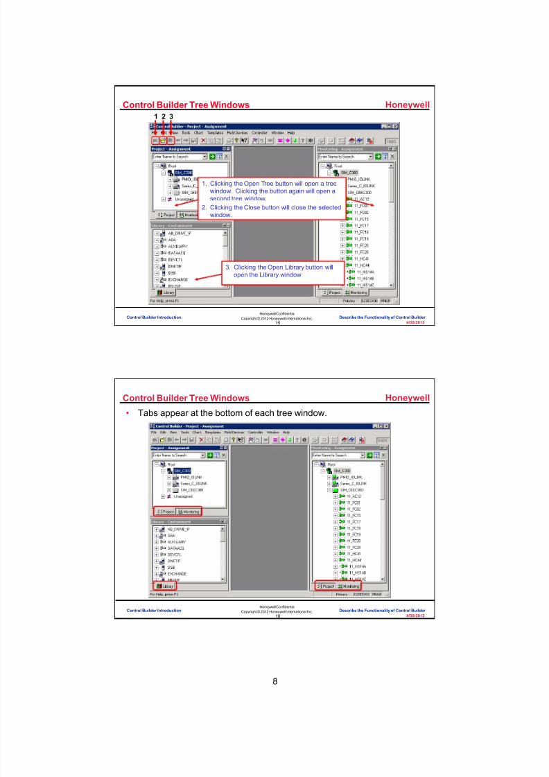
8/9/2019 Student Course Book- Automation
http://slidepdf.com/reader/full/student-course-book-automation 92/1165
8
Honeywell
Honeywell ConfidentialCopyright © 2012 Honeywell International Inc.
4/30/201215
Control Builder Tree Windows
3. Clicking the Open Library button willopen the Library window
3
1. Clicking the Open Tree button will open a treewindow. Clicking the button again will open asecond tree window.
2. Clicking the Close button will close the selectedwindow.
21
Control Builder Introduction Describe the Functionality of Control Builder
Honeywell
Honeywell ConfidentialCopyright © 2012 Honeywell International Inc.
4/30/201216
Control Builder Tree Windows
• Tabs appear at the bottom of each tree window.
Control Builder Introduction Describe the Functionality of Control Builder

8/9/2019 Student Course Book- Automation
http://slidepdf.com/reader/full/student-course-book-automation 93/1165
9
Honeywell
Honeywell ConfidentialCopyright © 2012 Honeywell International Inc.
4/30/201217
Control Builder Tabs
• The Project Tab displays the CPM, IOMs, CMs and SCMs in the current
project.
• The Project Tab is linked directly to the ERDB in the Experion Server.
Control Builder Introduction Describe the Functionality of Control Builder
Honeywell
Honeywell ConfidentialCopyright © 2012 Honeywell International Inc.
4/30/201218
Control Builder Tabs, contd.
• The Monitoring Tab:
– Displays all objects loaded to the controlprocessor module (CPM)
– Permits active modules to be viewed andcontrolled during process operations
Control Builder Introduction Describe the Functionality of Control Builder

8/9/2019 Student Course Book- Automation
http://slidepdf.com/reader/full/student-course-book-automation 94/1165
10
Honeywell
Honeywell ConfidentialCopyright © 2012 Honeywell International Inc.
4/30/201219
Control Builder Monitoring Tab
• To disable the online viewing of control
modules in the monitoring tab click:Chart > Disable Chart Monitoring
– The Control Module (CM) window mustbe open to make the change
• Selection are made per Control Module• Disabling Chart Monitoring only lasts as
long as the CM window is open – The next time the CM window is opened,
it will be re-enabled
• Generally, Chart Monitoring should beEnabled – When disabled, values shown on the
Monitoring Tab are from the ERDB (lastdownloaded), not from the controller
Control Builder Introduction Describe the Functionality of Control Builder
Honeywell
Honeywell ConfidentialCopyright © 2012 Honeywell International Inc.
4/30/201220
Control Builder Tabs
• The Library Tab displays all available system function blocks groupedinto type categories.
Control Builder Introduction Describe the Functionality of Control Builder

8/9/2019 Student Course Book- Automation
http://slidepdf.com/reader/full/student-course-book-automation 95/1165
11
Honeywell
Honeywell ConfidentialCopyright © 2012 Honeywell International Inc.
4/30/201221
Incorrect. Control builder is a graphical toolused to design control strategies for C200,
C300, ACE and SCE and save run time data.
Click anywhere to continue.
Incorrect. Control builder is a graphical toolused to design control strategies for C200,
C300, ACE and SCE and save run time data.
Click anywhere to continue.
Correct! Control builder is a graphical tool usedto design control strategies for C200, C300, ACE
and SCE and save run time data.
Click anywhere to continue.
Incorrect. Control builder is a graphical toolused to design control strategies for C200,
C300, ACE and SCE and save run time data.
Click anywhere to continue.
Question 1: Control Builder Functions
Correct - Click anywhere to continueIncorrect - Click anywhere to continueYou answered this correctly!
Your answer: The correct answer is:
You did not answer this question completelyYou must answer the question beforecontinuing
Submit Clear
Control Builder is :
A) An online documentation tool for C200controllers and Experion PKS servers
B) A tool used only for building graphics
C) A graphical tool used to design controlstrategies for C200, C300, ACE and SCEto save run time data
D) A graphical tool used to view plant graphics
Control Builder Introduction Describe the Functionality of Control Builder
Honeywell
Honeywell ConfidentialCopyright © 2012 Honeywell International Inc.
4/30/201222
Topics
• Starting Control Builder
• Control Builder Functions
• Control Builder Load Function
Control Builder Introduction Describe the Functionality of Control Builder

8/9/2019 Student Course Book- Automation
http://slidepdf.com/reader/full/student-course-book-automation 96/1165
12
Honeywell
Honeywell ConfidentialCopyright © 2012 Honeywell International Inc.
4/30/201223
Control Builder Load Function
Controller
Control Builder Introduction Describe the Functionality of Control Builder
Honeywell
Honeywell ConfidentialCopyright © 2012 Honeywell International Inc.
4/30/201224
Control Builder Load Function, contd.
Project / Monitor Tabs
Control Processor
ProjectTab
Monitor Tab
Controller
Server RTDB
Windows
Load
Upload
Update
Load (reload)Checkpoint
Restore fromCheckpoint
CheckpointFile
Control Builder Introduction Describe the Functionality of Control Builder
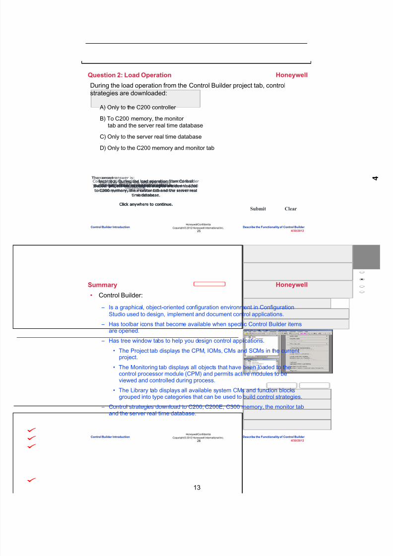
8/9/2019 Student Course Book- Automation
http://slidepdf.com/reader/full/student-course-book-automation 97/1165
13
Honeywell
Honeywell ConfidentialCopyright © 2012 Honeywell International Inc.
4/30/201225
During the load operation from the Control Builder project tab, controlstrategies are downloaded:
Question 2: Load Operation
Incorrect. During the load operation from ControlBuilder project tab, control strategies are downloadedto C200 memory, the monitor tab and the server real
time database.
Click anywhere to continue.
Correct! During the load operation from Control Builderproject tab, control strategies are downloaded to C200
memory, the monitor tab and the server real timedatabase.
Click anywhere to continue.
Incorrect. During the load operation from ControlBuilder project tab, control strategies are downloadedto C200 memory, the monitor tab and the server real
time database.
Click anywhere to continue.
Incorrect. During the load operation from ControlBuilder project tab, control strategies are downloadedto C200 memory, the monitor tab and the server real
time database.
Click anywhere to continue.
Correct - Click anywhere to continueIncorrect - Click anywhere to continueYou answered this correctly!
Your answer:The correct answer is:
You did not answer this question completelyYou must answer the question beforecontinuing
Submit Clear
A) Only to the C200 controller
B) To C200 memory, the monitortab and the server real time database
C) Only to the server real time database
D) Only to the C200 memory and monitor tab
Control Builder Introduction Describe the Functionality of Control Builder
Honeywell
Honeywell ConfidentialCopyright © 2012 Honeywell International Inc.
4/30/201226
Summary
• Control Builder:
– Is a graphical, object-oriented configuration environment in ConfigurationStudio used to design, implement and document control applications.
– Has toolbar icons that become available when specific Control Builder itemsare opened.
– Has tree window tabs to help you design control applications.
• The Project tab displays the CPM, IOMs, CMs and SCMs in the currentproject.
• The Monitoring tab displays all objects that have been loaded to thecontrol processor module (CPM) and permits active modules to beviewed and controlled during process.
• The Library tab displays all available system CMs and function blocksgrouped into type categories that can be used to build control strategies.
– Control strategies download to C200, C200E, C300 memory, the monitor taband the server real time database.
Control Builder Introduction Describe the Functionality of Control Builder

8/9/2019 Student Course Book- Automation
http://slidepdf.com/reader/full/student-course-book-automation 98/1165
14
Honeywell
Honeywell ConfidentialCopyright © 2012 Honeywell International Inc.
4/30/201227
Conclusion
Describe the Functionality of Control Builder
CompletionCertificate
Proceed to the next lesson in your course material.
Control Builder Introduction Describe the Functionality of Control Builder
Honeywell
Honeywell ConfidentialCopyright © 2012 Honeywell International Inc.
4/30/201228
This page intentionally left blank
Control Builder Introduction Describe the Functionality of Control Builder
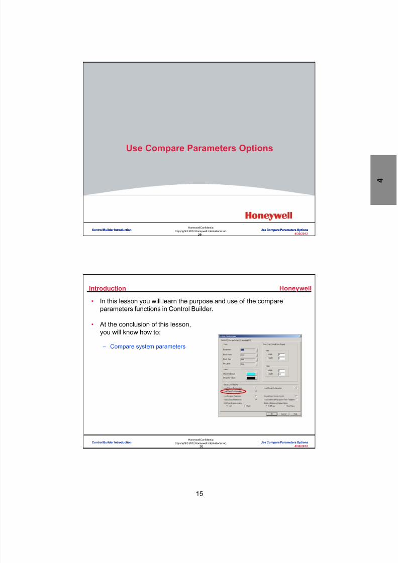
8/9/2019 Student Course Book- Automation
http://slidepdf.com/reader/full/student-course-book-automation 99/1165
15
29
Honeywell ConfidentialCopyright © 2012 Honeywell International Inc.
4/30/2012
Use Compare Parameters Options
Control Builder Introduction Use Compare Parameters OptionsControl Builder Introduction Use Compare Parameters Options
Honeywell
Honeywell ConfidentialCopyright © 2012 Honeywell International Inc.
4/30/201230
Introduction
• In this lesson you will learn the purpose and use of the compareparameters functions in Control Builder.
• At the conclusion of this lesson,you will know how to:
– Compare system parameters
Control Builder Introduction Use Compare Parameters Options

8/9/2019 Student Course Book- Automation
http://slidepdf.com/reader/full/student-course-book-automation 100/1165
16
Honeywell
Honeywell ConfidentialCopyright © 2012 Honeywell International Inc.
4/30/201231
Introduction
• The Compare Parameters Function:
– Allows you to compare the parameters on function blocks in your ERDB withparameters on the same function blocks loaded on your controller.
Control Builder Introduction Use Compare Parameters Options
Honeywell
Honeywell ConfidentialCopyright © 2012 Honeywell International Inc.
4/30/201232
Topics
• Comparing System Parameters
Control Builder Introduction Use Compare Parameters Options
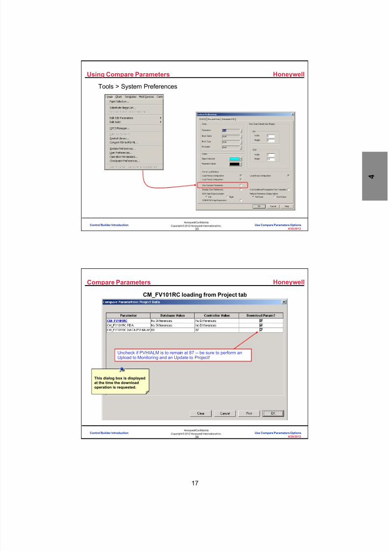
8/9/2019 Student Course Book- Automation
http://slidepdf.com/reader/full/student-course-book-automation 101/1165
17
Honeywell
Honeywell ConfidentialCopyright © 2012 Honeywell International Inc.
4/30/201233
Using Compare Parameters
Tools > System Preferences
Control Builder Introduction Use Compare Parameters Options
Honeywell
Honeywell ConfidentialCopyright © 2012 Honeywell International Inc.
4/30/201234
Compare Parameters
CM_FV101RC loading from Project tab
Uncheck if PVHIALM is to remain at 87 -- be sure to perform anUpload to Monitoring and an Update to Project!
This dialog box is displayedat the time the downloadoperation is requested.
Control Builder Introduction Use Compare Parameters Options

8/9/2019 Student Course Book- Automation
http://slidepdf.com/reader/full/student-course-book-automation 102/1165
18
Honeywell
Honeywell ConfidentialCopyright © 2012 Honeywell International Inc.
4/30/201235
Question 1: Comparing Parameters
No. All these statements are correct when theCompare Parameters function is active.
Click anywhere to continue.
No. All these statements are correct when theCompare Parameters function is active.
Click anywhere to continue.
No. All these statements are correct when theCompare Parameters function is active.
Click anywhere to continue.
Yes! All these statements are correct when theCompare Parameters function is active.
Click anywhere to continue.
Correct - Click anywhere to continueIncorrect - Click anywhere to continueYou answered this correctly!
Your answer:The correct answer is:
You did not answer this question completelyYou must answer the question beforecontinuing
Submit Clear
When the Compare Parameters function is active:
A) The Compare Parameters checkbox in theTools > System Preferences window is checked
B) Control Builder will inform you of any parameterdiscrepancies between the control module you areloading and the control module which resides on thecontroller
C) Control Builder will give you the option to keepcertain parameter values on the controller oroverwrite them with new values
D) All of the above
Control Builder Introduction Use Compare Parameters Options
Honeywell
Honeywell ConfidentialCopyright © 2012 Honeywell International Inc.
4/30/201236
Summary
• The Compare Parameters function in Control Builder:
– Compares parameters from function blocks in your ERDB with parametersfrom function blocks in your controller, giving you the opportunity to keep orwrite over existing values.
Control Builder Introduction Use Compare Parameters Options

8/9/2019 Student Course Book- Automation
http://slidepdf.com/reader/full/student-course-book-automation 103/1165
19
Honeywell
Honeywell ConfidentialCopyright © 2012 Honeywell International Inc.
4/30/201237
Conclusion
Identify Functionality of Compare Parameters
CompletionCertificate
Proceed to the next lesson in your course material.
Control Builder Introduction Use Compare Parameters Options
Honeywell
Honeywell ConfidentialCopyright © 2012 Honeywell International Inc.
4/30/201238
This page intentionally left blank
Control Builder Introduction Use Compare Parameters Options

8/9/2019 Student Course Book- Automation
http://slidepdf.com/reader/full/student-course-book-automation 104/1165
20
39
Honeywell ConfidentialCopyright © 2012 Honeywell International Inc.
4/30/2012
Use Control Builder Search
Control Builder Introduction Use Control Builder SearchControl Builder Introduction Use Control Builder Search
Honeywell
Honeywell ConfidentialCopyright © 2012 Honeywell International Inc.
4/30/201240
Introduction
• In this section we will learn about Control Builder search enhancementsintroduced in Experion R400
• At the end of this module you will be able to perform the functions suchas – Navigation from hyperlinks – Search, Sort and Filter Tags – Search function blocks in chart
Control Builder Introduction Use Control Builder Search

8/9/2019 Student Course Book- Automation
http://slidepdf.com/reader/full/student-course-book-automation 105/1165
21
Honeywell
Honeywell ConfidentialCopyright © 2012 Honeywell International Inc.
4/30/201241
Control Builder Navigation
• Right-click a wire connector to locate the source and destination blocks – Locate From Param option – source block – Locate to Param option – destination block – Navigation is available for connecting wires and not for block pins
Hover mouse over wireconnector to view tooltipindicating source and
destination blocks
DestinationBlock.Parameter will
be highlighted
SourceBlock.Parameter
will be highlighted
Control Builder Introduction Use Control Builder Search
Honeywell
Honeywell ConfidentialCopyright © 2012 Honeywell International Inc.
4/30/201242
Navigate to Block in Chart
Right-click block intree view and select
‘Locate in Chart’
Double-click block intree view
Control Builder Introduction Use Control Builder Search

8/9/2019 Student Course Book- Automation
http://slidepdf.com/reader/full/student-course-book-automation 106/1165
22
Honeywell
Honeywell ConfidentialCopyright © 2012 Honeywell International Inc.
4/30/201243
Navigation Using Hyperlinks
• Parameter Connector
• Cross Reference• SCM step output or condition
Right lick
R
Control Builder Introduction Use Control Builder Search
Honeywell
Honeywell ConfidentialCopyright © 2012 Honeywell International Inc.
4/30/201244
Selecting Hyperlink Color
• The following parameters will bedisplayed as hyperlinks – Parameter connectors, Cross-
references, SCM expressions
• The hyperlink color can beconfigured from SystemPreferences or User Preferences
Hyperlink color set in‘User Preferences’ will
override ‘SystemPreferences’
User Preferences are tiedto the Windows logon.
Config Studio logon andSignon Mgr logon do not
make any difference.
System Preferencesare copied to User
Preferences when anew Windows user logs
on.
Control Builder Introduction Use Control Builder Search

8/9/2019 Student Course Book- Automation
http://slidepdf.com/reader/full/student-course-book-automation 107/1165
23
Honeywell
Honeywell ConfidentialCopyright © 2012 Honeywell International Inc.
4/30/201245
Project Mode
Monitoring Mode
Hyperlink Color
Hyperlinks displayedin normal text colorin Monitoring mode
Configured hyperlinktext color displayed in
Project mode
Control Builder Introduction Use Control Builder Search
Honeywell
Honeywell ConfidentialCopyright © 2012 Honeywell International Inc.
4/30/201246
Navigation Scenarios
Target Parameter Chart Navigates to
In same SCM handler Corresponding Block/Parameter is selected
In different handler withinsame SCM
SCM Handler shall be invoked and corresponding block /parameter is selected
In different SCMChart for the particular SCM is opened and correspondingblock / parameter is selected
In CMChart is opened for the CM and corresponding block /parameter is selected
Directly belongs to a CM Chart of the tagged module is opened
Alias in the same SCM Configuration form is opened with the Alias tab active
DATA block parameter DATA block’s properties is opened with the FormulaParameters/Report Parameters tab active
Tagged block which does nothave a chart
Configuration form shall be opened for the tagged block.
Block which does not exist Tag name is displayed as ‘???’ and no hyperlink shall bedisplayed
Control Builder Introduction Use Control Builder Search

8/9/2019 Student Course Book- Automation
http://slidepdf.com/reader/full/student-course-book-automation 108/1165
24
Honeywell
Honeywell ConfidentialCopyright © 2012 Honeywell International Inc.
4/30/201247
Special Navigation Scenarios
Target Parameter Chart Navigates to
OPC parameter Configuration form of the OPC gateway shall be opened
Projected parameter Configuration form for the CM/SCM/RCM shall beopened with the Projected parameters tab select
Substitute Block Substitute Name List popup shall be opened with theSubstitute Blocks tab active
Substitute Parameter Substitute Name List popup shall be opened with theSubstitute Parameters tab active
Control Builder Introduction Use Control Builder Search
Honeywell
Honeywell ConfidentialCopyright © 2012 Honeywell International Inc.
4/30/201248
Search Tags Toolbar
• Experion R400 provides a search toolbar to search for tags in ControlBuilder
Project Window
Monitoring Window
Chart View
Control Builder Introduction Use Control Builder Search

8/9/2019 Student Course Book- Automation
http://slidepdf.com/reader/full/student-course-book-automation 109/1165
25
Honeywell
Honeywell ConfidentialCopyright © 2012 Honeywell International Inc.
4/30/201249
Find Block in Chart
• Enter the block name in the chart toolbar and click ‘search’ option
– Block will appear selected in chart
Block Names only.Wildcards not allowed.
Control Builder Introduction Use Control Builder Search
Honeywell
Honeywell ConfidentialCopyright © 2012 Honeywell International Inc.
4/30/201250
Navigating Between Chart Pages
Enter the page numberand press <Enter> key
or button
Page will bevisible in chart
view
Select to closethe chart toolbar
Right-click chart emptyspace and select ‘Display
Search Bar’
Control Builder Introduction Use Control Builder Search

8/9/2019 Student Course Book- Automation
http://slidepdf.com/reader/full/student-course-book-automation 110/1165
26
Honeywell
Honeywell ConfidentialCopyright © 2012 Honeywell International Inc.
4/30/201251
Navigating Between Chart Pages
Navigate to the last page
Navigate to the next page
Navigate to the previous page
Navigate to the first page
FunctionIcon
Control Builder Introduction Use Control Builder Search
Honeywell
Honeywell ConfidentialCopyright © 2012 Honeywell International Inc.
4/30/201252
Search Tags Toolbar – Project, Monitoring Tab
• Search tags in Project tab – Select name of required strategy – Press Enter key or click and the
corresponding chart is opened
• If user enters a tag name whichdoes not exist in the database,an error message is displayed
• If user enters a tag name that doesnot have a chart – Configuration form is opened – Example, search for a controller in
Project mode, controllerconfiguration form is opened
Enter initialtag name
Control Builder Introduction Use Control Builder Search

8/9/2019 Student Course Book- Automation
http://slidepdf.com/reader/full/student-course-book-automation 111/1165
27
Honeywell
Honeywell ConfidentialCopyright © 2012 Honeywell International Inc.
4/30/201253
Control Builder List View
• List View available in Control Builder to search, sort and filter tags
– List View can be opened from both Project and Monitoring modes – Cells are not editable in List View
• Filter row text is editable, for filtering text to be entered• List View can be filtered for to view details of a particular tag
Control Builder Introduction Use Control Builder Search
Honeywell
Honeywell ConfidentialCopyright © 2012 Honeywell International Inc.
4/30/201254
Open List View
• Select the Project tree/Monitoring tree – Select View List View – List View will open for Project/Monitoring
mode depending on selected tree view R
• Right-click empty space in tree view andselect ‘List’ View
Button to openList View
Control Builder Introduction Use Control Builder Search

8/9/2019 Student Course Book- Automation
http://slidepdf.com/reader/full/student-course-book-automation 112/1165
28
Honeywell
Honeywell ConfidentialCopyright © 2012 Honeywell International Inc.
4/30/201255
Default Columns in List View
• Default columns available in both Project and Monitoring List View
Columns Description
Name The name of the tag will be represented with an icon
Type Represents type of module for example FTE ,CPM,CPM200s,IOLIMS,CEE,CM etc
Parent Gives name of t he parent block
State Represents state of the block for example initial, loaded, changed (Project mode) oractive, inactive, error, database invalid (Monitoring mode)
Description Gives description of the block
Parent Asset Gives description of the parent asset associated with the block
Date Last Modified Gives description of the date and time the last modification was made to the block'sconfiguration
Control Builder Introduction Use Control Builder Search
Honeywell
Honeywell ConfidentialCopyright © 2012 Honeywell International Inc.
4/30/201256
List View Toolbar – Assignment Parent, Column Organizer
Parent Item Name Description
All TagsDisplays all strategies in the database. For examplecontrollers, CEEs, IOLINKs, CMs, SCM, RCM,
UCM, etc
Root Displays elements directly below the root. Forexample controllers, interface modules, unassigned
Controller Displays all tagged blocks under the controller
Unassigned Displays tagged blocks which are not assigned toany particular controller
Used for navigation todifferent controllers
Used to organizethe columns
Control Builder Introduction Use Control Builder Search

8/9/2019 Student Course Book- Automation
http://slidepdf.com/reader/full/student-course-book-automation 113/1165
29
Honeywell
Honeywell ConfidentialCopyright © 2012 Honeywell International Inc.
4/30/201257
List View Toolbar Buttons
Functions Icons Description
Clear Fi lters Clears a ll fi lters applied on the individual columns in Lis t view
Copy SelectedRows Copies selected rows along with the currently displayed parameters
Refresh Updates List View contents with the latest changes
Open Fil ters Opens the previously saved f il ters f rom any par ticular location
Save Filters Used to save the filter to an particular location
Change Context User can switch from Project mode to monitoring mode or vice versa
Last Update Displays the date & t ime when the contents of the Lis t view were las t updated
Control Builder Introduction Use Control Builder Search
Honeywell
Honeywell ConfidentialCopyright © 2012 Honeywell International Inc.
4/30/201258
Summary
• Hyperlinks are used to navigate to respective Control Strategies
• List View is available in Control Builder to sort, Search and filter tags
• Search Toolbar is added to search for tags in Control Builder
Control Builder Introduction Use Control Builder Search
8/9/2019 Student Course Book- Automation
http://slidepdf.com/reader/full/student-course-book-automation 114/1165
30
Honeywell
Honeywell ConfidentialCopyright © 2012 Honeywell International Inc.
4/30/201259
Conclusion
Use Control Builder Search
CompletionCertificate
Proceed to the next lesson in your course material.
Control Builder Introduction Use Control Builder Search
Honeywell
Honeywell ConfidentialCopyright © 2012 Honeywell International Inc.
4/30/201260
This page intentionally left blank
Control Builder Introduction Use Control Builder Search

8/9/2019 Student Course Book- Automation
http://slidepdf.com/reader/full/student-course-book-automation 115/1165
31
61
Honeywell ConfidentialCopyright © 2012 Honeywell International Inc.
4/30/2012
Describe How to Locate CB Concepts in KB
Control Builder Introduction Describe How to Locate CB Concepts in KBControl Builder Introduction Describe How to Locate CB Concepts in KB
Honeywell
Honeywell ConfidentialCopyright © 2012 Honeywell International Inc.
4/30/201262
Introduction
• In this lesson you will learn to locateinformation about Control Buildercomponents in Knowledge Builder.
• At the conclusion of this lesson, you willknow how to:
– Find function block information andtheory in Knowledge Builder
– Find parameter information inKnowledge Builder
Control Builder Introduction Describe How to Locate CB Concepts in KB
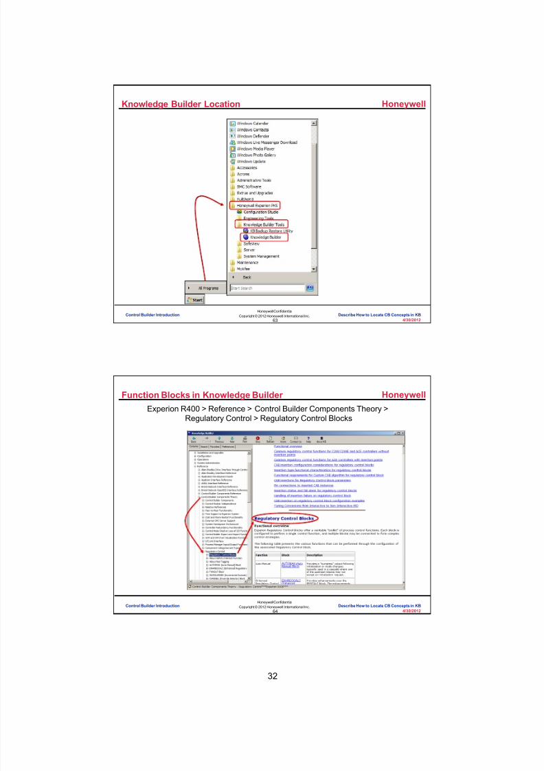
8/9/2019 Student Course Book- Automation
http://slidepdf.com/reader/full/student-course-book-automation 116/1165
32
Honeywell
Honeywell ConfidentialCopyright © 2012 Honeywell International Inc.
4/30/201263
Knowledge Builder Location
Control Builder Introduction Describe How to Locate CB Concepts in KB
Honeywell
Honeywell ConfidentialCopyright © 2012 Honeywell International Inc.
4/30/201264
Function Blocks in Knowledge BuilderExperion R400 > Reference > Control Builder Components Theory >
Regulatory Control > Regulatory Control Blocks
Control Builder Introduction Describe How to Locate CB Concepts in KB

8/9/2019 Student Course Book- Automation
http://slidepdf.com/reader/full/student-course-book-automation 117/1165
33
Honeywell
Honeywell ConfidentialCopyright © 2012 Honeywell International Inc.
4/30/201265
PID Block TheoryExperion PKS R400 > Reference > Control Builder Components Theory >
Regulatory Control > PID Block
PIDTheory
Control Builder Introduction Describe How to Locate CB Concepts in KB
Honeywell
Honeywell ConfidentialCopyright © 2012 Honeywell International Inc.
4/30/201266
Parameter Reference
Experion PKS R400 > Reference > Control Builder Parameter Reference
Control Builder Introduction Describe How to Locate CB Concepts in KB

8/9/2019 Student Course Book- Automation
http://slidepdf.com/reader/full/student-course-book-automation 118/1165
34
Honeywell
Honeywell ConfidentialCopyright © 2012 Honeywell International Inc.
4/30/201267
Where can you find information in Knowledge Builder for the CVEUHIparameter on a PID function block?
Question 1: Knowledge Builder Parameter Information
Correct - Click anywhere to continueIncorrect - Click anywhere to continueYou answered this correctly!
Your answer:The correct answer is:
You did not answer this question completelyYou must answer the question beforecontinuing
Submit Clear
No. The correct path to find information for the CVEUHIparameter on a PIDA function block in Knowledge Builder is
Experion PKS> Reference> Control Builder Parameter
Reference> CXXXX Parameters
Click anywhere to continue.
No. The correct path to find information for the CVEUHIparameter on a PIDA function block in Knowledge Builder is
Experion PKS> Reference> Control Builder ParameterReference> CXXXX Parameters
Click anywhere to continue.
Yes! The correct path to find information for the CVEUHIparameter on a PIDA function block in Knowledge Builder is
Experion PKS> Reference> Control Builder ParameterReference> CXXXX Parameters
Click anywhere to continue.
No. The correct path to find information for the CVEUHIparameter on a PIDA function block in Knowledge Builder is
Experion PKS> Reference> Control Builder ParameterReference> CXXXX Parameters
Click anywhere to continue.
A) Experion PKS> Reference> Control BuilderComponents Reference> CXXXX Parameters
B) Experion PKS> Reference> Control BuilderComponents Theory> CXXXX Parameters
C) Experion PKS> Reference> Control BuilderParameter Reference> CXXXX Parameters
D) None of the above
Control Builder Introduction Describe How to Locate CB Concepts in KB
Honeywell
Honeywell ConfidentialCopyright © 2012 Honeywell International Inc.
4/30/201268
Summary
• Read Knowledge Builder to learn about the components you’ll use tocreate control modules including: – Function block information and theory
(Experion PKS R400 > Reference > Control Builder Components Theory >Regulatory Control)
– Parameter information(Experion PKS R400 > Reference > Control Builder Parameter Reference)
Control Builder Introduction Describe How to Locate CB Concepts in KB

8/9/2019 Student Course Book- Automation
http://slidepdf.com/reader/full/student-course-book-automation 119/1165
35
Honeywell
Honeywell ConfidentialCopyright © 2012 Honeywell International Inc.
4/30/201269
Conclusion
Describe How to Locate CB Information in KB
CompletionCertificate
Proceed to the next lesson in your course material.
Control Builder Introduction Describe How to Locate CB Concepts in KB
Honeywell
Honeywell ConfidentialCopyright © 2012 Honeywell International Inc.
4/30/201270
This page intentionally left blank
Control Builder Introduction Describe How to Locate CB Concepts in KB

8/9/2019 Student Course Book- Automation
http://slidepdf.com/reader/full/student-course-book-automation 120/1165
Copyright © 201 2 Honeywell International Inc.
HPS Automation College written permission required to distributeHoneywell Confidential and Proprietary
This page was intentionally left blank.

8/9/2019 Student Course Book- Automation
http://slidepdf.com/reader/full/student-course-book-automation 121/1165
4/30/2012 Copyright © 2012 Honeywell International Inc. 1
HPS Automation College written permission required to distributeHoneywell Confidential and Proprietary
Topic: Control Builder Introduction
Contents
Open and Operate Control Builder ........................................................................................................ 3

8/9/2019 Student Course Book- Automation
http://slidepdf.com/reader/full/student-course-book-automation 122/1165
2 Copyright © 2012 Honeywell International Inc. 4/30/2012
HPS Automation College written permission required to distributeHoneywell Confidential and Proprietary
This page was intentionally left blank.

8/9/2019 Student Course Book- Automation
http://slidepdf.com/reader/full/student-course-book-automation 123/1165
Control Builder Introduction
Open and Operate Control Builder
4/30/2012 Copyright © 2012 Honeywell International Inc. 3
HPS Automation College written permission required to distributeHoneywell Confidential and Proprietary
Open and Operate Control Builder
Practice
The Purpose of this lesson is to demonstrate opening and operating Control Builder. After you
complete this lesson you will be able to :
• Identify the tabs used to make structural changes to an existing Control Module.
• Identify the tabs used to change parameters online.
Prerequisites
• An Experion PKS Server
• The server name for your system (E20ESV##_Server), where the ## symbols represent yourteam number; will be supplied by your instructor.
Introduction
• Control Builder is one of the Experion PKS Engineering Tools.
• Controllers can connect to a Server over FTE or over ControlNet.
• Control Builder can run on the Server or an Engineering Workstation. If controllers areconnected to the server over FTE, then a maximum of 12 Control Builder clients canconnect to a single Experion server. If controllers are connected to the server overControlNet, then a maximum of 4 Control Builder clients can connect to a single Experionserver.
• The devices, as well as control strategies, are created in Control Builder and downloaded tothe C200 Controller, C200E Controller, C300 Controller or ACE and the Experion PKSServer.
• Configuration Studio is required to launch Control Builder.
• In this course you will use the Manager (mngr) account to log into configuration studio.
• The user name entered when logging on to Configuration Studio determines the access levelof the user in Control Builder.
• View Only VIEW only
• Ack Only View and alarm acknowledgement
• OPER & SUPV Allow Operations
• ENGR & MNGR Allow Configurations
• The Experion PKS Operator profile can use a Windows account ID and password(Integrated Accounts ).

8/9/2019 Student Course Book- Automation
http://slidepdf.com/reader/full/student-course-book-automation 124/1165
Control Builder Introduction
Open and Operate Control Builder
4 Copyright © 2012 Honeywell International Inc. 4/30/2012
HPS Automation College written permission required to distributeHoneywell Confidential and Proprietary
• On a system with only one EPKS server, the Configuration Studio Connect window willshow both a System and a Server. Connecting to the System allows access to Enterprisewide configuration, while connecting to the Server only allows access to server specific
configuration. Generally, it is best to connect to the system rather than the server.• Identify the System and Server from the icon, as shown below. The server is also
categorized as Experion PKS Server in the Type column of the Connect window.
System/Server Icon Purpose
SystemUse Configuration Studio to connect to asystem to access the Enterprise ModelDatabase.
Server Use Configuration Studio to connect to aspecific server.
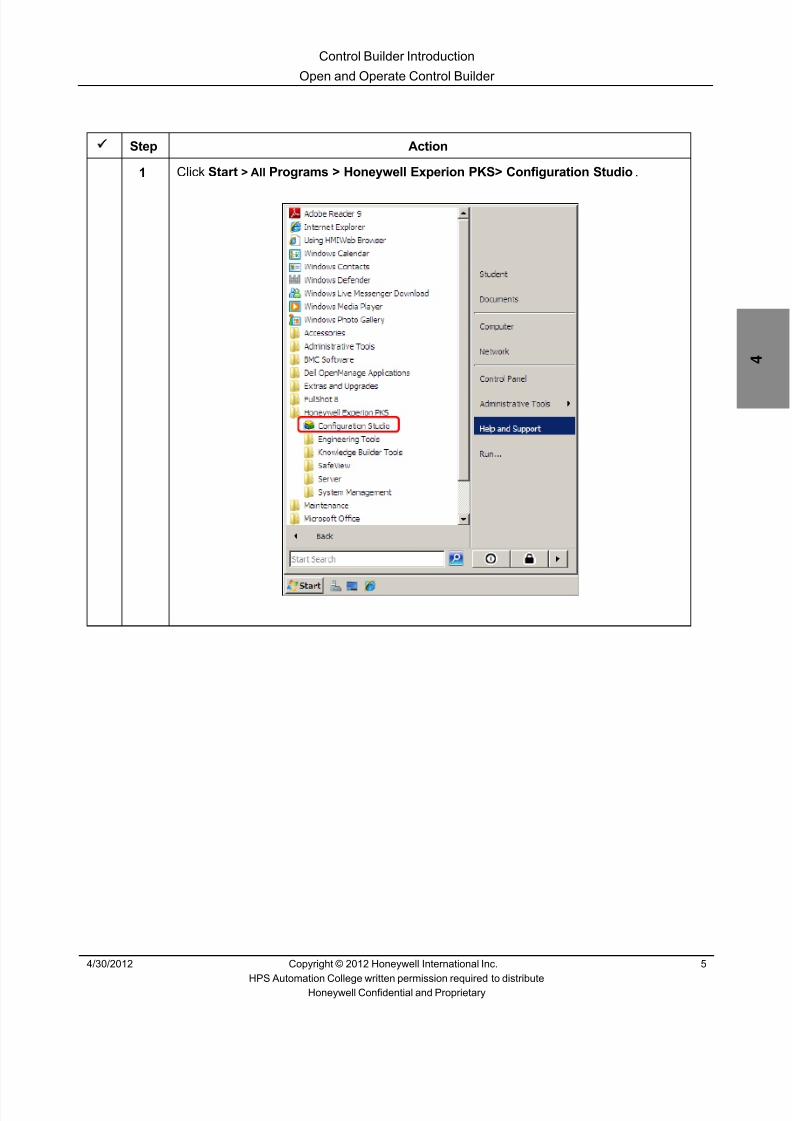
8/9/2019 Student Course Book- Automation
http://slidepdf.com/reader/full/student-course-book-automation 125/1165
Control Builder Introduction
Open and Operate Control Builder
4/30/2012 Copyright © 2012 Honeywell International Inc. 5
HPS Automation College written permission required to distributeHoneywell Confidential and Proprietary
Step Action
1 Click Start > All Programs > Honeywell Experion PKS> Configuration Studio .

8/9/2019 Student Course Book- Automation
http://slidepdf.com/reader/full/student-course-book-automation 126/1165
Control Builder Introduction
Open and Operate Control Builder
6 Copyright © 2012 Honeywell International Inc. 4/30/2012
HPS Automation College written permission required to distributeHoneywell Confidential and Proprietary
Step Action
2 In the Connect window, from the Local Targets tab, select your Experion Server (E20ESV##_Server) .
(Note your server list may appear different than the one shown below)
ATTENTION
The display, as seen above might, be different on yourscreen.For the class, the Server Name is E20ESV##_Server, where ## is the Student number.
Verify that the server name shown in the propertypanel (in gray) is the same as the server nameselected in the list above.

8/9/2019 Student Course Book- Automation
http://slidepdf.com/reader/full/student-course-book-automation 127/1165
Control Builder Introduction
Open and Operate Control Builder
4/30/2012 Copyright © 2012 Honeywell International Inc. 7
HPS Automation College written permission required to distributeHoneywell Confidential and Proprietary
Step Action
3 Click Connect .
4
ATTENTION
Depending on the credentials used to logon toWindows, it may not be necessary to provideadditional credentials (as shown) here.
In the Logon to window, enter the following information:
User name: mngr
Password: mngr1
Domain: < Traditional Operator Security>
5 Click OK .

8/9/2019 Student Course Book- Automation
http://slidepdf.com/reader/full/student-course-book-automation 128/1165
Control Builder Introduction
Open and Operate Control Builder
8 Copyright © 2012 Honeywell International Inc. 4/30/2012
HPS Automation College written permission required to distributeHoneywell Confidential and Proprietary
Step Action
6 In the Configuration Explorer tab, in the left-side pane, expand your server (click the“+” symbol next to the E20ESV##_Server – ServerName), to expand the correspondingtree.
ATTENTION
For the class, the Server Name is E20ESV##_Server, where ## is the Student number.
7 Select Control Strategy .

8/9/2019 Student Course Book- Automation
http://slidepdf.com/reader/full/student-course-book-automation 129/1165
Control Builder Introduction
Open and Operate Control Builder
4/30/2012 Copyright © 2012 Honeywell International Inc. 9
HPS Automation College written permission required to distributeHoneywell Confidential and Proprietary
Step Action
8 Select Configure process control strategies .
ATTENTION
The Control Builder application window will open.

8/9/2019 Student Course Book- Automation
http://slidepdf.com/reader/full/student-course-book-automation 130/1165
Control Builder Introduction
Open and Operate Control Builder
10 Copyright © 2012 Honeywell International Inc. 4/30/2012
HPS Automation College written permission required to distributeHoneywell Confidential and Proprietary
Step Action
9 In the Control Builder application window, you will see a screen, as illustrated below:
Your access level appears in the lower right corner as shown.
ATTENTION
The status line at the bottom of the Control Builderapplication indicates:
1. Sync if the ERDBs are synchronized (only onredundant servers. The example above is anon-redundant server).
2. The ERDB to which Control Builder isconnected. This should always be ‘Primary’which indicates that Control Builder isconnected to the B server (the primary ERDBis always on the B server).
3. The Experion Server to which Control Builderis connected.
4. The access level of the user.
Toolbar
Tree window

8/9/2019 Student Course Book- Automation
http://slidepdf.com/reader/full/student-course-book-automation 131/1165
Control Builder Introduction
Open and Operate Control Builder
4/30/2012 Copyright © 2012 Honeywell International Inc. 11
HPS Automation College written permission required to distributeHoneywell Confidential and Proprietary
Step Action
10 The toolbar gives you a graphical interface for accessing the different tools available inControl Builder. Some of the tools can also be found in the dropdown menus.
The details of the toolbar are as follows:
1 2 3 4 5 6 7 8 9 10 11 12 13 14 15 16 17 18 19 20 21 22 23 24 25 26 27
1 Open Tree. Open Tree Window
2 Close. Closes the Tree Window that has focus in Control Builder
3 Open Library
4 Move to the Left
5 Move to the Right
6 Save. Saves the active Control Drawing
7 Delete. Deletes the selected Object
8 Copy. Copies the selection and places on the clipboard
9 Paste. Pastes the item from clipboard contents
10 Print. Prints the selected pages of active document
11 Displays Program information
12 Displays Help information
13 Point Selection Command
14 Wire Connector
15 Parameter Connector
16 Assign Module to Execution Environment
17 Module Containment
18 Load Parameters
19 Upload Parameters
20 Substitute Names
21 QVCS (Qualification and Version Control System)
22 Toggle single item state
23 SCM Navigation
24 Field Device Description Unit
25 Wireless Device Description Unit
26 View Error Log 27 Change Scale

8/9/2019 Student Course Book- Automation
http://slidepdf.com/reader/full/student-course-book-automation 132/1165
Control Builder Introduction
Open and Operate Control Builder
12 Copyright © 2012 Honeywell International Inc. 4/30/2012
HPS Automation College written permission required to distributeHoneywell Confidential and Proprietary
Using Tree Windows
Step Action
1 If the tree windows are open, close them by clicking on the button on the right uppercorner of each window.
ATTENTION
You can also close the Tree Windows by selecting the
tree window and then clicking the button from thetoolbar.

8/9/2019 Student Course Book- Automation
http://slidepdf.com/reader/full/student-course-book-automation 133/1165
Control Builder Introduction
Open and Operate Control Builder
4/30/2012 Copyright © 2012 Honeywell International Inc. 13
HPS Automation College written permission required to distributeHoneywell Confidential and Proprietary
Step Action
2 Select View > Project/Monitor Tree to open the first Project/Monitor tree view on the leftside of your screen. Repeat the same procedure to open a second Project/Monitor treeview on the right hand side of the screen.
You can open a maximum of two Project/Monitor tree views at a time.
ATTENTION
Another way to open the Project/Monitor Tree Window
is to click the button on the toolbar.
3 Select View > Library Tree to open the Library Tree Window. You can open only oneLibrary Tree View.
ATTENTION
Another way to open the Library Tree window is by
clicking the button from the toolbar

8/9/2019 Student Course Book- Automation
http://slidepdf.com/reader/full/student-course-book-automation 134/1165
Control Builder Introduction
Open and Operate Control Builder
14 Copyright © 2012 Honeywell International Inc. 4/30/2012
HPS Automation College written permission required to distributeHoneywell Confidential and Proprietary
Step Action
4 Click and Drag the divider bar to the right to increase the size of the Project-Assignmentwindow.

8/9/2019 Student Course Book- Automation
http://slidepdf.com/reader/full/student-course-book-automation 135/1165
Control Builder Introduction
Open and Operate Control Builder
4/30/2012 Copyright © 2012 Honeywell International Inc. 15
HPS Automation College written permission required to distributeHoneywell Confidential and Proprietary
Step Action
5 There are 2 tabs in each Project/Monitor tree window: Project and Monitoring. Clickeach tab to toggle between them.
Project Tab
The following tasks are performed in the Project tab:• Create new CMs, SCMs and IOMs and define their parameters.• Design a Control Strategy through CMs and SCMs.• Save the Control Strategy.• Assign CMs and SCMs to the CEE (Control Execution Environment).• Load CMs and SCMs to the CPM (Control Processing Module).

8/9/2019 Student Course Book- Automation
http://slidepdf.com/reader/full/student-course-book-automation 136/1165
Control Builder Introduction
Open and Operate Control Builder
16 Copyright © 2012 Honeywell International Inc. 4/30/2012
HPS Automation College written permission required to distributeHoneywell Confidential and Proprietary
Step Action
6 Monitoring Tab
The following tasks are performed in the Monitoring tab:• Open CMs and SCMs for Online Monitoring.• Activate/Deactivate CMs and SCMs.• Change controller parameters and upload the changes.• Update changes to the Project database.• Change monitoring/configuration parameters on the faceplate of CM blocks.

8/9/2019 Student Course Book- Automation
http://slidepdf.com/reader/full/student-course-book-automation 137/1165
Control Builder Introduction
Open and Operate Control Builder
4/30/2012 Copyright © 2012 Honeywell International Inc. 17
HPS Automation College written permission required to distributeHoneywell Confidential and Proprietary
Step Action
7 Monitoring Tab Color Codes for C200/C200E:
1 2 3 4 5 6 7
1. Project Tree (gray)
2. Loaded, not monitoring (gray with black arrow)
3. Communication failure (red with black exclamation point)
4. Active (green)
5. Failed (red with white exclamation point)
6. Loaded, but no database (yellow with black exclamation point)
7. Idle / Inactive (blue)
ATTENTION
Refer to Knowledge Builder for more information oncolor codes:Experion R400 > Configuration > Control BuildingUser’s Guide > Creating a Control module >Control Builder block icon descriptions
8 Monitoring Tab Color Codes for C300:
1 2 3 4 5 6 7
1. Project Tree (gray)
2. No Communication (red)
3. No Database (Yellow)
4. Run or OK (Green with dotted border)
5. Idle (blue)
6. Run soft fail or Ok soft fail (green with cross mark)
7. Idle soft fail (blue with cross mark)
ATTENTION
Refer to Knowledge Builder for more information on color codes:Experion R400 > Configuration > C300 Controller User’s Guide>C300 Controller Operation > Control Builder block icondescriptions

8/9/2019 Student Course Book- Automation
http://slidepdf.com/reader/full/student-course-book-automation 138/1165
Control Builder Introduction
Open and Operate Control Builder
18 Copyright © 2012 Honeywell International Inc. 4/30/2012
HPS Automation College written permission required to distributeHoneywell Confidential and Proprietary
Step Action
9 The Library Tree window has just a single tab named Library.
Library Tab• Lists devices, IOMs, PM I/O, Rail I/O, and Function Blocks.• Click the “+” icon against an item in the Library Window to expand and view the
blocks.• Drag the blocks into a CM or SCM as appropriate, to form a control strategy.

8/9/2019 Student Course Book- Automation
http://slidepdf.com/reader/full/student-course-book-automation 139/1165
1
1
Honeywell ConfidentialCopyright © 2012 Honeywell International Inc.
4/13/2012
Describe the Configuration of C200/C200EHardware and I/O
C200/C200E Hardware Configuration Concepts Describe the Configuration of C200/C200E Hardware and I/OC200/C200E Hardware Configuration Concepts Describe the Configuration of C200/C200E Hardware and I/O
Honeywell
Honeywell ConfidentialCopyright © 2012 Honeywell International Inc.
4/13/20122
Introduction
• In this lesson you will learn to configure C200/C200E hardware and I/Ousing Control Builder.
• At the conclusion of this lesson, you will be able to:
– Identify C200/C200E hardware, slot numbers and addressing
– Configure and download hardware configurations for these components
C200/C200E Hardware Configuration Concepts Describe the Configuration of C200/C200E Hardware and I/O

8/9/2019 Student Course Book- Automation
http://slidepdf.com/reader/full/student-course-book-automation 140/1165
2
Honeywell
Honeywell ConfidentialCopyright © 2012 Honeywell International Inc.
4/13/20123
Topics
• Hardware and Slot Numbers
• Configuring the FTEB, Controller, and CEE
• Configuring IOMs
• Loading the Controller, CEE, and IOMs
• Activating a CEE
C200/C200E Hardware Configuration Concepts Describe the Configuration of C200/C200E Hardware and I/O
Honeywell
Honeywell ConfidentialCopyright © 2012 Honeywell International Inc.
4/13/20124
Control Processor (C200/C200E)
C200/C200E Chassis Hardware
• Below is an example C200/C200E chassis configured with:
1
2
3
4
5
6
7
8
5 6 7 8432
1
10-slot chassis
Power supply
ControlNet Interface (CNI)or FTE Bridge
IO Link Interface Module
Fieldbus Interface Module
Redundancy Module
CNI to Remote I/O
C200/C200E Hardware Configuration Concepts Describe the Configuration of C200/C200E Hardware and I/O

8/9/2019 Student Course Book- Automation
http://slidepdf.com/reader/full/student-course-book-automation 141/1165
3
Honeywell
Honeywell ConfidentialCopyright © 2012 Honeywell International Inc.
4/13/20125
Power Supply 1
2 34
56
7 8
0
9
C200/C200E I/O Slot Numbers
• To determine the slot location of C200/C200E related hardware youmust:
– Start counting at zero (do not count the power supply)
– Count from left to right
– Count both spaces if the module occupies two spaces
C200/C200E Hardware Configuration Concepts Describe the Configuration of C200/C200E Hardware and I/O
Honeywell
Honeywell ConfidentialCopyright © 2012 Honeywell International Inc.
4/13/20126
Topics
• Hardware and Slot Numbers
• Configuring the FTEB, Controller, and CEE
• Configuring IOMs
• Loading the Controller, CEE, and IOMs
• Activating a CEE
C200/C200E Hardware Configuration Concepts Describe the Configuration of C200/C200E Hardware and I/O

8/9/2019 Student Course Book- Automation
http://slidepdf.com/reader/full/student-course-book-automation 142/1165
4
Honeywell
Honeywell ConfidentialCopyright © 2012 Honeywell International Inc.
4/13/20127
Fault Tolerant Ethernet Bridge (FTEB)
• Single-wide chassis module
• Connects to FTE cable A and B
• Supports chassis redundancy
• Can only be used for SupervisoryControl Network connection
• ControlNet and downlink CNIsrequired for all I/O communicationsincluding peer-to-peer to AB devices
• Rotary switch for FTE Node Number (1 to 99) – The last octet of the IP address of the FTEB can be set to higher than 99 by
configuring the Base IP address accordingly in System Preferences.
C200/C200E Hardware Configuration Concepts Describe the Configuration of C200/C200E Hardware and I/O
Honeywell
Honeywell ConfidentialCopyright © 2012 Honeywell International Inc.
4/13/20128
Fault Tolerant Ethernet Bridge (FTEB), contd.
• The FTEB can be used for FIM-only connections to the supervisorynetwork.
• In the Project and Monitoring tabs in Control Builder you will see theFTEB as the root for the CPM.
• You will set up the FTEB using IP addresses.
• An FTE community can only have 99 FTEBs so you are limited to 49redundant pairs and 99 single FTEBs in one community.
• The FTE connection to the FTEB is 10Mbps.
– 10Mbps is only supported in FTE for connection from an FTEB to a switchand nowhere else
C200/C200E Hardware Configuration Concepts Describe the Configuration of C200/C200E Hardware and I/O

8/9/2019 Student Course Book- Automation
http://slidepdf.com/reader/full/student-course-book-automation 143/1165
5
Honeywell
Honeywell ConfidentialCopyright © 2012 Honeywell International Inc.
4/13/20129
Configuring a FTEB
Must match the hardware switchesfound on top of the FTEB card.
C200/C200E Hardware Configuration Concepts Describe the Configuration of C200/C200E Hardware and I/O
Honeywell
Honeywell ConfidentialCopyright © 2012 Honeywell International Inc.
4/13/201210
Question 1: FTEB Index Numbering
Incorrect. ‘110' is not a valid FTEB indexnumber. The last octet of t he FTEB IP address
can be set to higher than 99 by configuring thebase IP address accordingly in SystemPreferences in Cont rol Builder.
Click anywhere to continue.
Incorrect. ‘110' is not a valid FTEB indexnumber. The last octet of t he FTEB IP address
can be set to higher than 99 by configuring thebase IP address accordingly in SystemPreferences in Cont rol Builder.
Click anywhere to continue.
Correct. ‘110' is not a valid FTEB indexnumber. The last octet of t he FTEB IP address
can be set to higher than 99 by configuring thebase IP address accordingly in SystemPreferences in Cont rol Builder.
Click anywhere to continue.
Incorrect. ‘110' is not a valid FTEB indexnumber. The last octet of t he FTEB IP address
can be set to higher than 99 by configuring thebase IP address accordingly in SystemPreferences in Cont rol Builder.
Click anywhere to continue.
Correct - Click anywhere to continueIncorrect - Click anywhere to continueYou answered this correctly!
Your answer:The correct answer is:
You did not answer this question completelyYou must answer the question before
continuing
Submit Clear
Which of the following is not a valid FTEB device index number? A) 15
B) 99
C) 110
D) 1
C200/C200E Hardware Configuration Concepts Describe the Configuration of C200/C200E Hardware and I/O

8/9/2019 Student Course Book- Automation
http://slidepdf.com/reader/full/student-course-book-automation 144/1165
6
Honeywell
Honeywell ConfidentialCopyright © 2012 Honeywell International Inc.
4/13/201211
Configuring a C200
Follow these steps to add anew control processor
module (CPM) from the pull-down menus.
C200/C200E Hardware Configuration Concepts Describe the Configuration of C200/C200E Hardware and I/O
Honeywell
Honeywell ConfidentialCopyright © 2012 Honeywell International Inc.
4/13/201212
• Data entry detailswill be provided inthe lab exercise
Configuring a C200 – CPM Main Tab – ControlNet
MAC ID of CNI Cardconnected to server
Driver Name
Tag Name & Item Name
ControlNet
CNI slot #
Slot number of CPM
Alarm reporting by CEE
Check for the redundant controller andthen enter its name.
C200/C200E Hardware Configuration Concepts Describe the Configuration of C200/C200E Hardware and I/O
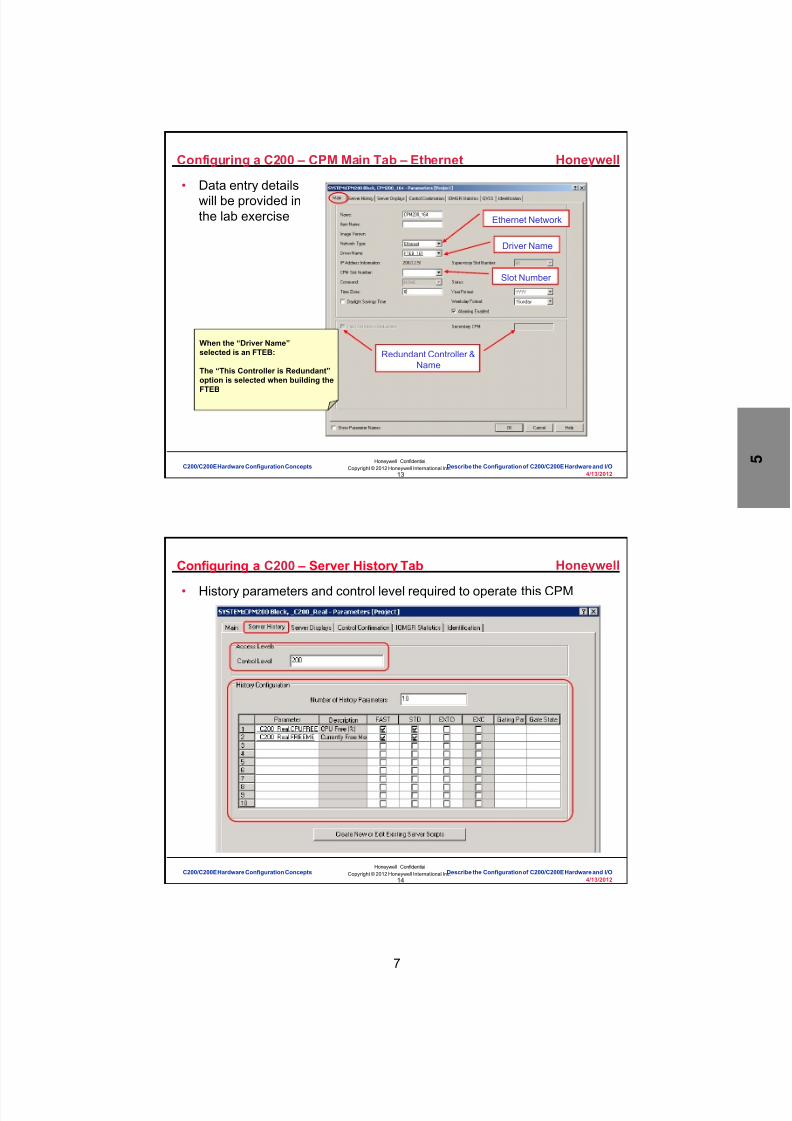
8/9/2019 Student Course Book- Automation
http://slidepdf.com/reader/full/student-course-book-automation 145/1165
7
Honeywell
Honeywell ConfidentialCopyright © 2012 Honeywell International Inc.
4/13/201213
Configuring a C200 – CPM Main Tab – Ethernet
• Data entry detailswill be provided inthe lab exercise Ethernet Network
Driver Name
Redundant Controller &Name
When the “Driver Name”selected is an FTEB:
The “This Controller is Redundant”option is selected when building the
FTEB
Slot Number
C200/C200E Hardware Configuration Concepts Describe the Configuration of C200/C200E Hardware and I/O
Honeywell
Honeywell ConfidentialCopyright © 2012 Honeywell International Inc.
4/13/201214
• History parameters and control level required to operate this CPM
Configuring a C200 – Server History Tab
C200/C200E Hardware Configuration Concepts Describe the Configuration of C200/C200E Hardware and I/O

8/9/2019 Student Course Book- Automation
http://slidepdf.com/reader/full/student-course-book-automation 146/1165
8
Honeywell
Honeywell ConfidentialCopyright © 2012 Honeywell International Inc.
4/13/201215
Configuring a C200 – Group and Trend Assignment
Point, group, trend and associateddisplays (that reside on the server) are
defined on the Server Displays tab.
Select OK to close and save t he newcontroller.
C200/C200E Hardware Configuration Concepts Describe the Configuration of C200/C200E Hardware and I/O
Honeywell
Honeywell ConfidentialCopyright © 2012 Honeywell International Inc.
4/13/201216
Question 2: Supervisory MAC Address for a CPM
Incorrect. The Supervisory MAC address is the MACaddress of the CNI card connected to the server.
Click anywhere to continue.
Incorrect. The Supervisory MAC address is the MACaddress of the CNI card connected to the server.
Click anywhere to continue.
Incorrect. The Supervisory MAC address is the MACaddress of the CNI card connected to the server.
Click anywhere to continue.
Correct! The Supervisory MAC address is the MACaddress of the CNI card connected to the server.
Click anywhere to continue.
Correct - Click anywhere to continueIncorrect - Click anywhere to continueYou answered this correctly!Your answer:The correct answer is:You did not answer this question completelyYou must answer the question before
continuing
Submit Clear
When configuring a ControlNet connectedcontrol processor module (CPM) in ControlBuilder, which MAC address is entered asthe Supervisory MAC address?
A) The device index of FTEB card
B) The MAC address of the PCIC card
C) The MAC address of CNI cardconnected to the I/O rack
D) The MAC address of CNI cardconnected to server
C200/C200E Hardware Configuration Concepts Describe the Configuration of C200/C200E Hardware and I/O

8/9/2019 Student Course Book- Automation
http://slidepdf.com/reader/full/student-course-book-automation 147/1165
9
Honeywell
Honeywell ConfidentialCopyright © 2012 Honeywell International Inc.
4/13/201217
Configuring a C200E
Follow the Step to configurenew C200E controller
C200/C200E Hardware Configuration Concepts Describe the Configuration of C200/C200E Hardware and I/O
Honeywell
Honeywell ConfidentialCopyright © 2012 Honeywell International Inc.
4/13/201218
Configure C200E – Main Tab
C200/C200E Hardware Configuration Concepts Describe the Configuration of C200/C200E Hardware and I/O

8/9/2019 Student Course Book- Automation
http://slidepdf.com/reader/full/student-course-book-automation 148/1165
10
Honeywell
Honeywell ConfidentialCopyright © 2012 Honeywell International Inc.
4/13/201219
C200E Configuration – Simulation Tab
Select the check box , if the nodeis connected to ControlNet
Network
Select the check box forsimulation Node Configuration
• To create either a C200E or a SIM-C200E – File > New > Controllers > C200E – Control Processor Module (16M)
C200/C200E Hardware Configuration Concepts Describe the Configuration of C200/C200E Hardware and I/O
Honeywell
Honeywell ConfidentialCopyright © 2012 Honeywell International Inc.
4/13/201220
Initiating the Configuration of the CEE
• The Control Processor Module (CPM) and its Control ExecutionEnvironment (CEE) are configured but not yet downloaded.
Click the + sign to expandthe CPM in the Project tab.
Double-click the CEE toopen its configuration
form.
C200/C200E Hardware Configuration Concepts Describe the Configuration of C200/C200E Hardware and I/O

8/9/2019 Student Course Book- Automation
http://slidepdf.com/reader/full/student-course-book-automation 149/1165
11
Honeywell
Honeywell ConfidentialCopyright © 2012 Honeywell International Inc.
4/13/201221
CEE – Main Tab – Name, Base Execution Period
• The Main tab configuration of the CEE block.
System assigned or user configured uniquename (consisting of up to 16 characters and
at least one letter A-Z)
Indicates the base executionperiod for the CEE block
- 5 ms (non-Redundant)- 50 ms (non-Redundant or
Redundant)
C200/C200E Hardware Configuration Concepts Describe the Configuration of C200/C200E Hardware and I/O
Honeywell
Honeywell ConfidentialCopyright © 2012 Honeywell International Inc.
4/13/201222
Main Tab – C200 CEE Command State
• The Main tab is used for the configuration of the CEEC200 block.
Indicates the current state of the CEE
Select the command to change theCEESTATE parameter; options are:IDLE, COLDSTART, WARMSTART
Select the user level required toperform a coldstart or a warmstart
Select the user level required to
Idle the CEE
Determines whether program access isallowed to command the CEE from Idle
to Run and from Run to Idle
C200/C200E Hardware Configuration Concepts Describe the Configuration of C200/C200E Hardware and I/O

8/9/2019 Student Course Book- Automation
http://slidepdf.com/reader/full/student-course-book-automation 150/1165
12
Honeywell
Honeywell ConfidentialCopyright © 2012 Honeywell International Inc.
4/13/201223
Main Tab – C200 Alarm Info
Allows user to set the alarm reportingfunction used when an alarm condition
is detected by the function block
Indicates if an alarm has beendetected with this function block
C200/C200E Hardware Configuration Concepts Describe the Configuration of C200/C200E Hardware and I/O
Honeywell
Honeywell ConfidentialCopyright © 2012 Honeywell International Inc.
4/13/201224
Main Tab C200E CEE – Simulation, State, and Time Info
Shows the time zone offset valuefor the controller location
Select the CEE state aftera RAM retention restartOptions: Idle, LastCold,
LastWarm
Indicates Simulation State ofC200E controller in Monitoring
Explained later
C200/C200E Hardware Configuration Concepts Describe the Configuration of C200/C200E Hardware and I/O

8/9/2019 Student Course Book- Automation
http://slidepdf.com/reader/full/student-course-book-automation 151/1165
13
Honeywell
Honeywell ConfidentialCopyright © 2012 Honeywell International Inc.
4/13/201225
Restart Initialization Delay
• Integer configuration value establishes an initialization delay, inseconds, to be applied to all CMs within the CEE following a restart – RSTRTINIDLY allows CMs within CEE to come into alignment with the
process following a RAM Retention Restart or a Checkpoint Restore – Default value is 10 seconds – When CEE restart occurs, CEE.RSTRTINIDLY and CM.RELOADINIDLY are
used to compute starting value of CM.CURRELINIDLY as follows• CM.CURRELINIDLY = CM.RELOADINIDLY + ( CEE.RSTRTINIDLY /
CM.PERIOD)
• Applies to: C200E, C300, ACE
C200/C200E Hardware Configuration Concepts Describe the Configuration of C200/C200E Hardware and I/O
Honeywell
Honeywell ConfidentialCopyright © 2012 Honeywell International Inc.
4/13/201226
Batch Tab
Indicates the buffer size allocated for batchevents generated by SCM/RCM.
Options are:None, Small, Medium, and Large
Small = 120 eventsMedium = 240 events
Large = 720 events
This item can bechanged only fromthe Project tab.
• Applies to: C200, C200E, C300, ACE
C200/C200E Hardware Configuration Concepts Describe the Configuration of C200/C200E Hardware and I/O

8/9/2019 Student Course Book- Automation
http://slidepdf.com/reader/full/student-course-book-automation 152/1165
14
Honeywell
Honeywell ConfidentialCopyright © 2012 Honeywell International Inc.
4/13/201227
Server History and Server Displays Tabs
• Server History Tab -- Access Levels, History Configuration
C200/C200E Hardware Configuration Concepts Describe the Configuration of C200/C200E Hardware and I/O
Honeywell
Honeywell ConfidentialCopyright © 2012 Honeywell International Inc.
4/13/201228
• Hardware and Slot Numbers
• Configuring the FTEB, Controller, and CEE
• Configuring IOMs
• Loading the Controller, CEE, and IOMs
• Activating a CEE
Topics
C200/C200E Hardware Configuration Concepts Describe the Configuration of C200/C200E Hardware and I/O

8/9/2019 Student Course Book- Automation
http://slidepdf.com/reader/full/student-course-book-automation 153/1165
15
Honeywell
Honeywell ConfidentialCopyright © 2012 Honeywell International Inc.
4/13/201229
Methods to Add Input/Output Modules (IOMs)
• Three methods to add an IOM: – From the Library:
• Drag and drop onto the CEE• Drag and drop onto a blank area
– From the Menu:• File>New>I/O Modules>IOMODULE>
1 2
3
C200/C200E Hardware Configuration Concepts Describe the Configuration of C200/C200E Hardware and I/O
Honeywell
Honeywell ConfidentialCopyright © 2012 Honeywell International Inc.
4/13/201230
Different Actions Based on Method Used
Method Used Name NewDialog?
Put inUnassigned?
Drop on CEE Yes No
Drop to Blank Yes Yes
Menu No Yes
Depending on the methodused to add the IOM, yourIOM may be automaticallyassigned to your CEE, or itmay be put in Unassigned.
Depending on the methodused to add the IOM, youmay or may not be presentedwith this dialog box.
C200/C200E Hardware Configuration Concepts Describe the Configuration of C200/C200E Hardware and I/O

8/9/2019 Student Course Book- Automation
http://slidepdf.com/reader/full/student-course-book-automation 154/1165
16
Honeywell
Honeywell ConfidentialCopyright © 2012 Honeywell International Inc.
4/13/201231
Configuring an IOM
Module slot number
MAC address of the remoterack’s CNI card0 if IOM is in CPM chassis
Slot number of the CNI inthe processor rack throughwhich this card will
communicate.Zero if IOM is in CPM chassis
DoubleClick
C200/C200E Hardware Configuration Concepts Describe the Configuration of C200/C200E Hardware and I/O
Honeywell
Honeywell ConfidentialCopyright © 2012 Honeywell International Inc.
4/13/201232
Assigning IOMs
Assignedto CEE2
31a
1b
Required if the “menu” methodwas used, or if the IOM wasdropped onto a blank area.
C200/C200E Hardware Configuration Concepts Describe the Configuration of C200/C200E Hardware and I/O

8/9/2019 Student Course Book- Automation
http://slidepdf.com/reader/full/student-course-book-automation 155/1165
17
Honeywell
Honeywell ConfidentialCopyright © 2012 Honeywell International Inc.
4/13/201233
Question 3: Configuring an IOM
Incorrect. Before you can load IOMs, they must be
assigned to the Control Execution Environment.Click anywhere to continue.
Correct! Before you can load IOMs, they must be
assigned to the Control Execution Environment.Click anywhere to continue.
Incorrect. Before you can load IOMs, they must be
assigned to the Control Execution Environment.Click anywhere to continue.
Incorrect. Before you can load IOMs, they must be
assigned to the Control Execution Environment.Click anywhere to continue.
Correct - Click anywhere to continueIncorrect - Click anywhere to continueYou answered this correctly!
Your answer:The correct answer is:
You did not answer this question completelyYou must answer the question beforecontinuing
Submit Clear
Before loading an IOM, it must be:
A) Activated
B) Assigned
C) Renamed
D) Validated
C200/C200E Hardware Configuration Concepts Describe the Configuration of C200/C200E Hardware and I/O
Honeywell
Honeywell ConfidentialCopyright © 2012 Honeywell International Inc.
4/13/201234
• Hardware and Slot Numbers
• Configuring the FTEB, Controller, and CEE
• Configuring IOMs
• Loading the Controller, CEE, and IOMs
• Activating a CEE
Topics
C200/C200E Hardware Configuration Concepts Describe the Configuration of C200/C200E Hardware and I/O

8/9/2019 Student Course Book- Automation
http://slidepdf.com/reader/full/student-course-book-automation 156/1165
18
Honeywell
Honeywell ConfidentialCopyright © 2012 Honeywell International Inc.
4/13/201235
Loading the Controller, CEE and IOMs
Not yetloaded
RightClick
Load:C200 & CEE
Load with Contents:C200 & CEE & IOMs
C200/C200E Hardware Configuration Concepts Describe the Configuration of C200/C200E Hardware and I/O
Honeywell
Honeywell ConfidentialCopyright © 2012 Honeywell International Inc.
4/13/201236
Loading the Controller, CEE and IOMs, contd.
Note:You can decide to have themodules go to the active stateautomatically by clicking thischeckbox, with the Post Load State
selected, to be “Active.”
Verify that theitems to load arechecked.
C200/C200E Hardware Configuration Concepts Describe the Configuration of C200/C200E Hardware and I/O

8/9/2019 Student Course Book- Automation
http://slidepdf.com/reader/full/student-course-book-automation 157/1165
19
Honeywell
Honeywell ConfidentialCopyright © 2012 Honeywell International Inc.
4/13/201237
Topics
• Hardware and Slot Numbers
• Configuring the FTEB, Controller, and CEE
• Configuring IOMs
• Loading the Controller, CEE, and IOMs
• Activating a CEE
C200/C200E Hardware Configuration Concepts Describe the Configuration of C200/C200E Hardware and I/O
Honeywell
Honeywell ConfidentialCopyright © 2012 Honeywell International Inc.
4/13/201238
Activating a Control Strategy
Double-click CEE
Select COLDSTARTor WARMSTART
This can be done onlyfrom the monitoringtab (not the Project tab).
Another method is toright-click on the CEEand select “ChangeState”.
C200/C200E Hardware Configuration Concepts Describe the Configuration of C200/C200E Hardware and I/O

8/9/2019 Student Course Book- Automation
http://slidepdf.com/reader/full/student-course-book-automation 158/1165
20
Honeywell
Honeywell ConfidentialCopyright © 2012 Honeywell International Inc.
4/13/201239
Activating a Control Strategy, contd.
lue The object is not running (inactive)
Green The object is running (active)
Red Communication failure
Click Yes
C200/C200E Hardware Configuration Concepts Describe the Configuration of C200/C200E Hardware and I/O
Honeywell
Honeywell ConfidentialCopyright © 2012 Honeywell International Inc.
4/13/201240
Summary
• When configuring and loading C200/C200E hardware and I/O in Control Builder,remember:
– To determine the IOM slot number of hardware in the C200 chassis, start counting atzero, but do not count the power supply, count from left to right and count both spacesif the module occupies two spaces.
– An FTEB Index number can not be set to higher than 99.
• However, the last octet of the IP address can be higher than 99
– The Supervisory MAC address of the CPM is the MAC address of the CNI cardconnected to the server.
– C200E has a separate Simulation Tab to configure a simulated C200E
– Before loading the Control Processor Module (CPM), its Control Execution
Environment (CEE), and I/O modules (IOMs):
• Configure the CPM, its CEE and I/O modules (IOMs)
• Assign the IOMs to the CEE
C200/C200E Hardware Configuration Concepts Describe the Configuration of C200/C200E Hardware and I/O

8/9/2019 Student Course Book- Automation
http://slidepdf.com/reader/full/student-course-book-automation 159/1165
21
Honeywell
Honeywell ConfidentialCopyright © 2012 Honeywell International Inc.
4/13/201241
Conclusion
Describe the Configuration of C200 Hardware and I/O
CompletionCertificate
Proceed to the next lesson in your course material.
C200/C200E Hardware Configuration Concepts Describe the Configuration of C200/C200E Hardware and I/O
Honeywell
Honeywell ConfidentialCopyright © 2012 Honeywell International Inc.
4/13/201242
This page intentionally left blank
C200/C200E Hardware Configuration Concepts Describe the Configuration of C200/C200E Hardware and I/O

8/9/2019 Student Course Book- Automation
http://slidepdf.com/reader/full/student-course-book-automation 160/1165
Copyright © 201 2 Honeywell International Inc.
HPS Automation College written permission required to distributeHoneywell Confidential and Proprietary
This page was intentionally left blank.

8/9/2019 Student Course Book- Automation
http://slidepdf.com/reader/full/student-course-book-automation 161/1165
1
1
Honeywell ConfidentialCopyright © 2012 Honeywell International Inc.
4/13/2012
Describe C300 and Series C I/O Configuration
C300 Hardware Configuration Concepts Describe C300 and Series C I/O ConfigurationC300 Hardware Configuration Concepts Describe C300 and Series C I/O Configuration
Honeywell
Honeywell ConfidentialCopyright © 2012 Honeywell International Inc.
4/13/20122
Introduction
• In this lesson you will learn to configure a C300 Controller andSeries C I/O.
• PMIO configuration will be discussed in a separate lesson.• The steps for configuration are similar to the C200/C200E configuration:
– Add a new Controller to the Project hierarchy• Control Builder adds the CEE and two IOLINK modules
– Configure the Controller – Configure the CEE – Configure the IOLINKs (PMIO or Series C IO) – Configure the IOMs – Assign the IOMs to the IOLINKs – Load the Controller, CEE, IOLINKS, and the IOMs – Activate the CEE
C300 Hardware Configuration Concepts Describe C300 and Series C I/O Configuration

8/9/2019 Student Course Book- Automation
http://slidepdf.com/reader/full/student-course-book-automation 162/1165
2
Honeywell
Honeywell ConfidentialCopyright © 2012 Honeywell International Inc.
4/13/20123
Topics
• Configuring the C300 and CEE
• Configuring IOLINKs
• Configuring IOMs
• Loading the C300, IOLINKs, and IOMs
• Activating the C300
C300 Hardware Configuration Concepts Describe C300 and Series C I/O Configuration
Honeywell
Honeywell ConfidentialCopyright © 2012 Honeywell International Inc.
4/13/20124
Configuring a Controller
Follow these steps toadd a new controller
from the pull-downmenus
C300 Hardware Configuration Concepts Describe C300 and Series C I/O Configuration

8/9/2019 Student Course Book- Automation
http://slidepdf.com/reader/full/student-course-book-automation 163/1165
3
Honeywell
Honeywell ConfidentialCopyright © 2012 Honeywell International Inc.
4/13/20125
Configuring a Controller – Main Tab
Data entrydetails will beprovided in thelab exercise.
Check forredundant controller
Select toConfigure aSIM-C300
Enter details of SimulationEnvironment Node
Name
Device indexNumber of C300
This number mustmatch the number of the switches on theC300 IOTA.
C300 Hardware Configuration Concepts Describe C300 and Series C I/O Configuration
Honeywell
Honeywell ConfidentialCopyright © 2012 Honeywell International Inc.
4/13/20126
Configuring a Controller – Server History Tab
History parameters and control level required to operate this C300
C300 Hardware Configuration Concepts Describe C300 and Series C I/O Configuration

8/9/2019 Student Course Book- Automation
http://slidepdf.com/reader/full/student-course-book-automation 164/1165
4
Honeywell
Honeywell ConfidentialCopyright © 2012 Honeywell International Inc.
4/13/20127
Configuring a Controller – Group and Trend Assignment
Point, group, trend and associateddisplays (residing on the server) aredefined on the Server Displays tab
Select OK to close andsave the new controller
C300 Hardware Configuration Concepts Describe C300 and Series C I/O Configuration
Honeywell
Honeywell ConfidentialCopyright © 2012 Honeywell International Inc.
4/13/20128
C300 View in Control Builder
Redundancy
C300, CEE, andIOLINKs
C300 Hardware Configuration Concepts Describe C300 and Series C I/O Configuration

8/9/2019 Student Course Book- Automation
http://slidepdf.com/reader/full/student-course-book-automation 165/1165
5
Honeywell
Honeywell ConfidentialCopyright © 2012 Honeywell International Inc.
4/13/20129
Configuring a CEE
Data entry details willbe provided in the Labexercise
For C300, the options forBase Execution Period are:50mS and 20mS
20mS is selected onlyfor the Turbo Machinery C300
C300 Hardware Configuration Concepts Describe C300 and Series C I/O Configuration
Honeywell
Honeywell ConfidentialCopyright © 2012 Honeywell International Inc.
4/13/201210
Main Tab – C300 CEE RAM Retention
• Main Tab – Powerup Restart SettingsShows the CEE state after
a RAM retention restartOptions: Idle, LastCold,LastWarm, LastTimeout
Shows the power down timeout that indicates whether theCEE block executes a warm or cold restart upon power up
Only used if LastTimeout was selected for the CEE State
Shows the time zone offset valuefor the controller location
C300 Hardware Configuration Concepts Describe C300 and Series C I/O Configuration

8/9/2019 Student Course Book- Automation
http://slidepdf.com/reader/full/student-course-book-automation 166/1165
6
Honeywell
Honeywell ConfidentialCopyright © 2012 Honeywell International Inc.
4/13/201211
Which of the following statements is not true for C300 configuration?
Question 1: C300 Configuration
Incorrect. The false statement is "Only oneIOLINK is automatically created for Series C
I/O".When a C300 controller is created in
Control Builder 2 IOLINKS are automaticallyadded.
Click anywhere to continue.
Incorrect. The false statement is "Only oneIOLINK is automatically created for Series C
I/O".When a C300 controller is created in
Control Builder 2 IOLINKS are automaticallyadded.
Click anywhere to continue.
Correct! When a C300 controller is created inControl Builder 2 IOLINKS are automatically
added.Click anywhere to continue.
Incorrect. The false statement is "Only oneIOLINK is automatically created for Series C
I/O". When a C300 controller is created in
Control Builder 2 IOLINKS are automaticallyadded.
Click anywhere to continue.
Correct - Click anywhere to continueIncorrect - Click anywhere to continueYou answered this correctly!
Your answer:The correct answer is:
You did not answer this question completelyYou must answer the question before
continuing
Submit Clear
A) Device Index number on the C300IOTA needs to be specified
B) 2 IOLINKs are automatically created
C) Only one IOLINK is automatically created forSeries C I/O
D) 50ms Base Execution Period is supported for non-redundant C300 configuration
C300 Hardware Configuration Concepts Describe C300 and Series C I/O Configuration
Honeywell
Honeywell ConfidentialCopyright © 2012 Honeywell International Inc.
4/13/201212
Topics
• Configuring the C300 and CEE
• Configuring IOLINKs
• Configuring IOMs
• Loading the C300, IOLINKs, and IOMs
• Activating the C300
C300 Hardware Configuration Concepts Describe C300 and Series C I/O Configuration

8/9/2019 Student Course Book- Automation
http://slidepdf.com/reader/full/student-course-book-automation 167/1165
7
Honeywell
Honeywell ConfidentialCopyright © 2012 Honeywell International Inc.
4/13/201213
IOLINK Configuration – Link 1
I/O Link number 1 Cable - Gray
I/O family selection
C300 Hardware Configuration Concepts Describe C300 and Series C I/O Configuration
Honeywell
Honeywell ConfidentialCopyright © 2012 Honeywell International Inc.
4/13/201214
IOLINK Configuration – Link 2
I/O Link number 2 Cable - Violet
C300 Hardware Configuration Concepts Describe C300 and Series C I/O Configuration

8/9/2019 Student Course Book- Automation
http://slidepdf.com/reader/full/student-course-book-automation 168/1165
8
Honeywell
Honeywell ConfidentialCopyright © 2012 Honeywell International Inc.
4/13/201215
Configuring C300 Hardware
• The Control Processor Module (CPM) and its Control ExecutionEnvironment (CEE) are now configured but not yet downloaded.
C300 Hardware Configuration Concepts Describe C300 and Series C I/O Configuration
Honeywell
Honeywell ConfidentialCopyright © 2012 Honeywell International Inc.
4/13/201216
Question 2: IOLINK Configuration
Correct - Click anywhere to continueIncorrect - Click anywhere to continueYou answered this correctly!
Your answer: The correct answer is:
You did not answer this question completelyYou must answer the question before
continuing
Submit Clear
Correct! When configuring an IOLINK only onetype of IO family can be connected to each
IOLINK i.e. Series C or PM IO, one type on eachlink.
Click anywhere to continue.
Incorrect. When configuring an IOLINK only onetype of IO family can be connected to each
IOLINK i.e. Series C or PM IO, one type on eachlink.
Click anywhere to continue.
Incorrect. When configuring an IOLINK only onetype of IO family can be connected to each
IOLINK i.e. Series C or PM IO, one type on eachlink.
Click anywhere to continue.
Which of the following items are specified during IOLINK configuration?
A) Series C or PM IO, one type on each IOLINK
B) Series A I/O type
C) Whether Series C and PM IO are to be used onthe same IOLINK
C300 Hardware Configuration Concepts Describe C300 and Series C I/O Configuration

8/9/2019 Student Course Book- Automation
http://slidepdf.com/reader/full/student-course-book-automation 169/1165
9
Honeywell
Honeywell ConfidentialCopyright © 2012 Honeywell International Inc.
4/13/201217
Topics
• Configuring the C300 and CEE• Configuring IOLINKs
• Configuring IOMs
• Loading the C300, IOLINKs, and IOMs
• Activating the C300
C300 Hardware Configuration Concepts Describe C300 and Series C I/O Configuration
Honeywell
Honeywell ConfidentialCopyright © 2012 Honeywell International Inc.
4/13/201218
Methods to Add Input/Output Modules (IOMs)
• Three methods to add an IOM: – From the Library:
• Drag and drop onto an IOLINK• Drag and drop onto a blank area
– From the Menu:• File>New>I/O Modules>SERIES_C_IO
12
3
C300 Hardware Configuration Concepts Describe C300 and Series C I/O Configuration

8/9/2019 Student Course Book- Automation
http://slidepdf.com/reader/full/student-course-book-automation 170/1165
10
Honeywell
Honeywell ConfidentialCopyright © 2012 Honeywell International Inc.
4/13/201219
Different Actions Based on Method Used
Method Used Name NewDialog?
Put inUnassigned?
Drop on IOLINK Yes No
Drop to Blank Yes Yes
Menu No Yes
Depending on the methodused to add the IOM, your
IOM may be automaticallyassigned to your IOLINK, or itmay be put in Unassigned.
Depending on the methodused to add the IOM, youmay or may not be presentedwith this dialog box.
C300 Hardware Configuration Concepts Describe C300 and Series C I/O Configuration
Honeywell
Honeywell ConfidentialCopyright © 2012 Honeywell International Inc.
4/13/201220
Configuring an IOM
Double lick
IOM number
This number mustmatch the number of the jumper plug onthe IOTA
C300 Hardware Configuration Concepts Describe C300 and Series C I/O Configuration

8/9/2019 Student Course Book- Automation
http://slidepdf.com/reader/full/student-course-book-automation 171/1165
11
Honeywell
Honeywell ConfidentialCopyright © 2012 Honeywell International Inc.
4/13/201221
Assigning IOMs
2
31a
1b
Required if the “menu” methodwas used, or if the IOM wasdropped onto a blank area.
Assignedto IOLink
C300 Hardware Configuration Concepts Describe C300 and Series C I/O Configuration
Honeywell
Honeywell ConfidentialCopyright © 2012 Honeywell International Inc.
4/13/201222
Topics
• Configuring the C300 and CEE
• Configuring IOLINKs
• Configuring IOMs
• Loading the C300, IOLINKs, and IOMs
• Activating the C300
C300 Hardware Configuration Concepts Describe C300 and Series C I/O Configuration

8/9/2019 Student Course Book- Automation
http://slidepdf.com/reader/full/student-course-book-automation 172/1165
12
Honeywell
Honeywell ConfidentialCopyright © 2012 Honeywell International Inc.
4/13/201223
Loading the Controller, CEE and IOMs
Not yetloaded
Right lick
Load:C300, CEE, IOLinks
Load with Contents:C300, CEE, IOLinks, IOMs
lick
C300 Hardware Configuration Concepts Describe C300 and Series C I/O Configuration
Honeywell
Honeywell ConfidentialCopyright © 2012 Honeywell International Inc.
4/13/201224
Loading the Controller, CEE and IOMs – Post Load State
Verify that the itemsto load arechecked.
Note:You can decide tohave the modules goto the run stateautomatically byclicking this checkboxwith the Post LoadState selected to be“Run”.
C300 Hardware Configuration Concepts Describe C300 and Series C I/O Configuration

8/9/2019 Student Course Book- Automation
http://slidepdf.com/reader/full/student-course-book-automation 173/1165
13
Honeywell
Honeywell ConfidentialCopyright © 2012 Honeywell International Inc.
4/13/201225
Question 3: IOP Configuration
Incorrect. The assigned I/O modules appearunder the IOLINK tree in Project tab.
Click anywhere to continue.
Correct! The assigned I/O modules appearunder the IOLINK tree in Project tab.
Click anywhere to continue.
Incorrect. The assigned I/O modules appearunder the IOLINK tree in Project tab.
Click anywhere to continue.
Correct - Click anywhere to continueIncorrect - Click anywhere to continueYou answered this correctly!
Your answer: The correct answer is:
You did not answer this question completelyYou must answer the question before
continuing
Submit Clear
Assigned Series C I/O modules appear under:
A) The Unassigned tree in Project tab
B) Their associated IOLINK tree in Project tab
C) Directly under the CEE tree in Project tab
C300 Hardware Configuration Concepts Describe C300 and Series C I/O Configuration
Honeywell
Honeywell ConfidentialCopyright © 2012 Honeywell International Inc.
4/13/201226
Topics
• Configuring the C300 and CEE
• Configuring IOLINKs
• Configuring IOMs
• Loading the C300, IOLINKs and IOMs
• Activating the C300
C300 Hardware Configuration Concepts Describe C300 and Series C I/O Configuration

8/9/2019 Student Course Book- Automation
http://slidepdf.com/reader/full/student-course-book-automation 174/1165
14
Honeywell
Honeywell ConfidentialCopyright © 2012 Honeywell International Inc.
4/13/201227
Activating a Control Strategy
Select WARMSTART
This can be done onlyfrom the monitoringtab (not the Project tab).
Another method is toright-click on the CEEand select “ChangeState”.
C300 Hardware Configuration Concepts Describe C300 and Series C I/O Configuration
Honeywell
Honeywell ConfidentialCopyright © 2012 Honeywell International Inc.
4/13/201228
Changing the State of a Controller – Confirming Change
Blue : The object is not running (inactive)
Green : The object is running (active)Red : Communication failure
Click Yes
C300 Hardware Configuration Concepts Describe C300 and Series C I/O Configuration

8/9/2019 Student Course Book- Automation
http://slidepdf.com/reader/full/student-course-book-automation 175/1165
15
Honeywell
Honeywell ConfidentialCopyright © 2012 Honeywell International Inc.
4/13/201229
Summary
• When you configure and load C300 hardware and I/O in Control Builder,remember: – Series C IOM number is set on the IOTA of the corresponding IOM using a
numbered jumper plug.
– The device index of C300 can be found on the rotary switches located infront of the C300 board.
– Before loading the C300 controller, its Control Execution Environment (CEE)and IOLINKs:
• Configure the Controller, its CEE and IOLINKs
• Define the I/O Family type on each IOLINK
• Assign the IOMs to the respective IOLINKs
– Load the C300 controller, its Control Execution Environment (CEE) andIOLINKs
– Activate the C300 from the CEE.
C300 Hardware Configuration Concepts Describe C300 and Series C I/O Configuration
Honeywell
Honeywell ConfidentialCopyright © 2012 Honeywell International Inc.
4/13/201230
Conclusion
Describe C300 and Series C I/O Configuration
CompletionCertificate
Proceed to the next lesson in your course material.
C300 Hardware Configuration Concepts Describe C300 and Series C I/O Configuration

8/9/2019 Student Course Book- Automation
http://slidepdf.com/reader/full/student-course-book-automation 176/1165
Copyright © 201 2 Honeywell International Inc.
HPS Automation College written permission required to distributeHoneywell Confidential and Proprietary
This page was intentionally left blank.

8/9/2019 Student Course Book- Automation
http://slidepdf.com/reader/full/student-course-book-automation 177/1165
1
1
Honeywell ConfidentialCopyright © 2012 Honeywell International Inc.
4/13/2012
Describe the Import/Export Procedure inControl Builder
Control Builder Import / Export Procedure Describe the Import/Export Procedure in Control BuilderControl Builder Import / Export Procedure Describe the Import/Export Procedure in Control Builder
Honeywell
Honeywell ConfidentialCopyright © 2012 Honeywell International Inc.
4/13/20122
Introduction
• In this lesson you will learn how toimport and export control strategyconfigurations from one server toanother.
• At the conclusion of this lesson,you will be able to:
– Describe how to export controlstrategy configurations from aControl Builder project.
– Describe how to import control
strategy configurations into aControl Builder project.
Control Builder Import / Export Procedure Describe the Import/Export Procedure in Control Builder

8/9/2019 Student Course Book- Automation
http://slidepdf.com/reader/full/student-course-book-automation 178/1165
2
Honeywell
Honeywell ConfidentialCopyright © 2012 Honeywell International Inc.
4/13/20123
Control Builder - Export
• The Export function lets you
export all or a portion of theERDB viewed in the ProjectTree to the Ixport folder or auser-defined location.
• The exported portions or all of the
ERDB are stored in the Ixport folder atthe directory location:
C:\Users\Public\Public Documents\Honeywell\Experion PKS\Ixport
Control Builder Import / Export Procedure Describe the Import/Export Procedure in Control Builder
Honeywell
Honeywell ConfidentialCopyright © 2012 Honeywell International Inc.
4/13/20124
Control Builder - Import/Export
CM, SCM and hardware configurations (IOMs) can be moved betweenservers using the Import/Export function
Control Builder (Server 1)
Control Builder (Server 2)
ControlStrategy
Configuration
ProjectTree
ControlStrategy
Configuration
ProjectTree
Ixport Directory
xport
ata
Import ata
The servers must berunning the samerelease.
Controllers, CEEs,IOLINKs should bebuilt “from scratch”,not exported/imported.
Control Builder Import / Export Procedure Describe the Import/Export Procedure in Control Builder

8/9/2019 Student Course Book- Automation
http://slidepdf.com/reader/full/student-course-book-automation 179/1165
3
Honeywell
Honeywell ConfidentialCopyright © 2012 Honeywell International Inc.
4/13/20125
Control Builder - Export
• In Control Builder, select File > Export to call up the dialog box shown:
Import\Export textfiles target location
All items in currentproject use selectionbuttons (or use<Ctl> + mouseselect or <Shift> +mouse select toexport specific CMsfrom the pointwindow)
List of items to Exportbased on selectionsfrom window(Export.sl)
Select to start export
All items in Currentproject
Control Builder Import / Export Procedure Describe the Import/Export Procedure in Control Builder
Honeywell
Honeywell ConfidentialCopyright © 2012 Honeywell International Inc.
4/13/20126
Control Builder - Export
Exporting Data Dialog Box
Control Builder Import / Export Procedure Describe the Import/Export Procedure in Control Builder

8/9/2019 Student Course Book- Automation
http://slidepdf.com/reader/full/student-course-book-automation 180/1165
4
Honeywell
Honeywell ConfidentialCopyright © 2012 Honeywell International Inc.
4/13/20127
Control Builder - Import
• In Control Builder, select File > Import to call up the dialog box shown:
Import\Export text Filestarget location
Import and Assign
Select to start Import
Use selection buttons(or use <Ctl> + mouseselect or <Shift> +mouse select to importspecific CMs from thePoint window)
List of items to Importbased on Selections fromWindow (Import.sl)
The export functionautomatically createsan ‘export.sl’ file.
All items in CurrentImport/Export text Fileslocation
Control Builder Import / Export Procedure Describe the Import/Export Procedure in Control Builder
Honeywell
Honeywell ConfidentialCopyright © 2012 Honeywell International Inc.
4/13/20128
Question 1: Importing and Exporting
Incorrect. CMs, SCMs and the hardwareconfiguration can be copied and restored to
another se rver.
Click anywhere to continue.
Correct! CMs, SCMs and the hardwareconfiguration can be copied and restored to
another se rver.
Click anywhere to continue.
Incorrect. CMs, SCMs and the hardwareconfiguration can be copied and restored to
another se rver.
Click anywhere to continue.
Incorrect. CMs, SCMs and the hardwareconfiguration can be copied and restored to
another se rver.
Click anywhere to continue.
Correct - Click anywhere to continueIncorrect - Click anywhere to continueYou answered this correctly!
Your answer: The correct answer is:
You did not answer this question completelyYou must answer the question beforecontinuing
Submit Clear
Which of the following statements best describes the import/export function? A) Only the hardware configuration
can be moved between servers
B) CMs, SCMs and the hardwareconfiguration can be copied andrestored to another server
C) Only CMs can be moved betweenservers
D) None of the above
Control Builder Import / Export Procedure Describe the Import/Export Procedure in Control Builder

8/9/2019 Student Course Book- Automation
http://slidepdf.com/reader/full/student-course-book-automation 181/1165
5
Honeywell
Honeywell ConfidentialCopyright © 2012 Honeywell International Inc.
4/13/20129
Summary
• The Import/Export function in Control Builder:
– Allows you to copy CM, SCM and hardware configurations from oneserver’s ERDB to another server’s ERDB
• The ‘export server’ and the ‘import server’ must be running the samerelease
• Controllers should be built “from scratch”, not exported / imported
– Includes CEE and IOLinks
Control Builder Import / Export Procedure Describe the Import/Export Procedure in Control Builder
Honeywell
Honeywell ConfidentialCopyright © 2012 Honeywell International Inc.
4/13/201210
Conclusion
Describe the Import/Export Procedure in Control Builder
CompletionCertificate
Proceed to the Configure C200 Hardware in a Simulation ControlEnvironment (SCE) and Import the Remaining I/O Modules into the SCE
lab exercises
Control Builder Import / Export Procedure Describe the Import/Export Procedure in Control Builder

8/9/2019 Student Course Book- Automation
http://slidepdf.com/reader/full/student-course-book-automation 182/1165
Copyright © 201 2 Honeywell International Inc.
HPS Automation College written permission required to distributeHoneywell Confidential and Proprietary
This page was intentionally left blank.

8/9/2019 Student Course Book- Automation
http://slidepdf.com/reader/full/student-course-book-automation 183/1165
4/13/2012 Copyright © 2012 Honeywell International Inc. 1
HPS Automation College written permission required to distributeHoneywell Confidential and Proprietary
Topic: Controller Hardware Configuration
Contents
Instructions for: Configure Controller Hardware .................................................................................... 3
Configure C200E Controller and Series A IOM in SIM-C200E ............................................................ 5
Import the Remaining Series A IO Modules into the SCE ................................................................... 29
Configure C300 Controller and Series C IOM in SIM-C300 ................................................................ 37
Import the Remaining Series C IO in to SIM-C300 ............................................................................. 49

8/9/2019 Student Course Book- Automation
http://slidepdf.com/reader/full/student-course-book-automation 184/1165
2 Copyright © 2012 Honeywell International Inc. 4/13/2012
HPS Automation College written permission required to distributeHoneywell Confidential and Proprietary
This page was intentionally left blank.

8/9/2019 Student Course Book- Automation
http://slidepdf.com/reader/full/student-course-book-automation 185/1165
Controller Hardware Configuration
Instructions for: Configure Controller Hardware
4/13/2012 Copyright © 2012 Honeywell International Inc. 3
HPS Automation College written permission required to distributeHoneywell Confidential and Proprietary
Instructions for: Configure Controller Hardware
Introduction
This portion of the lab describes how to follow the ‘Controller Hardware Configuration’ lab.
Procedure
Step Action
1 Select ONLY one of the following:
Read the IMPORTANT information below.
In class, students can choose to configure hardware and points for either a C200E, or aC300. It is not possible for students to complete labs for both. Therefore, each studentmust decide whether they will configure hardware and points for a C200E, or a C300.
There are several reasons that only one or the other can be done: Time allocated to thecourse (1 week), Tag names cannot be duplicated on a server, the AC “simulator” Excelspread sheet, the AC HMI Web pre-built displays, etc.
Please select whether you will be performing labs for the C200E (and Series A I/Omodules) or for C300 (and Series C I/O Modules). Select only one of the following:
_______ C200E (and Series A I/O modules)
_______ C300 (and Series C I/O Modules)
2 If you selected:
C200E (and Series A I/O modules):
Complete ONLY the following portions of this lab (the first two sections):
Configure C200E Controller and Series A IOM in SIM-C200E
Import the Remaining Series A IO Modules into the SCE
C300 (and Series C I/O Modules):Complete ONLY the following portions of this lab (the second two sections):
Configure C300 Controller and Series C IOM in SIM-C300
Import the Remaining Series C IO Modules into the SCE

8/9/2019 Student Course Book- Automation
http://slidepdf.com/reader/full/student-course-book-automation 186/1165
Controller Hardware Configuration
Instructions for: Configure Controller Hardware
4 Copyright © 2012 Honeywell International Inc. 4/13/2012
HPS Automation College written permission required to distributeHoneywell Confidential and Proprietary
This page was intentionally left blank.

8/9/2019 Student Course Book- Automation
http://slidepdf.com/reader/full/student-course-book-automation 187/1165
Controller Hardware Configuration
Configure C200E Controller and Series A IOM in SIM-C200E
4/13/2012 Copyright © 2012 Honeywell International Inc. 5
HPS Automation College written permission required to distributeHoneywell Confidential and Proprietary
Configure C200E Controller and Series A IOM in SIM-C200E
Practice
Introduction
In this lab, you will learn to create a SIM-C200E. You will also learn that an associated ControlExecution Environment (CEE) block represents an installed SIM-C200E controller in the ProjectTree. The CEE supports execution of Control Modules (CMs) for simulating control applications.The CEE runs in the SCE controller as a software layer built on top of the control softwareinfrastructure.
Objective
• Configure a SIM-C200E (Simulation Control Environment) Controller in Control Builder
• Configure a CEE in Control Builder
• Configure Input Output Modules. (3 Analog Input modules, 2 Analog Output Modules, 1Digital Input Module, 2 Digital Output modules)
Prerequisites
• Experion PKS Server setup and configured to run SCE controller
Note:
You must note the names, for the SIM-C200E, CMs, and FBs used in Control Modules and IOMs,
in your lab exercises. These are the names used, in the Excel tie back sheet, for simulation purpose.

8/9/2019 Student Course Book- Automation
http://slidepdf.com/reader/full/student-course-book-automation 188/1165
Controller Hardware Configuration
Configure C200E Controller and Series A IOM in SIM-C200E
6 Copyright © 2012 Honeywell International Inc. 4/13/2012
HPS Automation College written permission required to distributeHoneywell Confidential and Proprietary
Complete the Following Steps in Control Builder
Create an SIM-C200E
Step Action
1 Launch Control Builder Application from Configuration Studio
2 Add a new Simulation Controller
With the Project Tab selected, select File > New > Controllers > C200E
ATTENTION
C200E and SIM-C200E share the same template

8/9/2019 Student Course Book- Automation
http://slidepdf.com/reader/full/student-course-book-automation 189/1165
Controller Hardware Configuration
Configure C200E Controller and Series A IOM in SIM-C200E
4/13/2012 Copyright © 2012 Honeywell International Inc. 7
HPS Automation College written permission required to distributeHoneywell Confidential and Proprietary
Step Action
3 Enter the Data for each configuration parameter for Main tab
Name: SCE59 and Item Name: SCE59_item
The name can be up to 16 characters
4 Alarm Enabled : Ensure this checkbox is checked to enable alarming for this SCE
Let all other values on this tab remain at the defaults
5 Select Load to simulation Environment .

8/9/2019 Student Course Book- Automation
http://slidepdf.com/reader/full/student-course-book-automation 190/1165
Controller Hardware Configuration
Configure C200E Controller and Series A IOM in SIM-C200E
8 Copyright © 2012 Honeywell International Inc. 4/13/2012
HPS Automation College written permission required to distributeHoneywell Confidential and Proprietary
Step Action
6
ATTENTION
Enter the Host Name of your Experion Server(E20ESVxx) and press Enter. The Host IP Addressshould automatically be entered. If it is not, get the IPaddress from your course manager.
Host Name – Simulation node name

8/9/2019 Student Course Book- Automation
http://slidepdf.com/reader/full/student-course-book-automation 191/1165
Controller Hardware Configuration
Configure C200E Controller and Series A IOM in SIM-C200E
4/13/2012 Copyright © 2012 Honeywell International Inc. 9
HPS Automation College written permission required to distributeHoneywell Confidential and Proprietary
Step Action
7 Click the Server History Tab. Keep the default values on this tab
A) Control Level: The minimum control level (between 0 and 255) required toperform supervisory control on this point. The default is 200 . Keep the default.
B) History Configuration Grid: Supports the configuration of associated pointparameters for history collection. Leave it blank.
A
B

8/9/2019 Student Course Book- Automation
http://slidepdf.com/reader/full/student-course-book-automation 192/1165
Controller Hardware Configuration
Configure C200E Controller and Series A IOM in SIM-C200E
10 Copyright © 2012 Honeywell International Inc. 4/13/2012
HPS Automation College written permission required to distributeHoneywell Confidential and Proprietary
Step Action
8 Click the Server Displays Tab. Keep the default values .
A) The Point Detail Display is used to show detailed point information. If you leave thevalue as (default) , the standard detail display is used for the point type. You cancreate your own point detail display and enter the display name here.
B) The Group Detail Display is used to display point information when the point is partof a group. If you leave the value as (default) , the standard group display is used.
Accept all the defaults on this tab
9 Click the OK button
A
B

8/9/2019 Student Course Book- Automation
http://slidepdf.com/reader/full/student-course-book-automation 193/1165
Controller Hardware Configuration
Configure C200E Controller and Series A IOM in SIM-C200E
4/13/2012 Copyright © 2012 Honeywell International Inc. 11
HPS Automation College written permission required to distributeHoneywell Confidential and Proprietary
Step Action
10 Click the PLUS sign “ +” to the left of SCE59• Notice that SCE/CEESCEFB blocks are created in Project tab
ATTENTION
The Name of CEESIMC200FB_135, as shown in the above display,may be different than your CEE.
11 Right-click your CEE and select Module Properties

8/9/2019 Student Course Book- Automation
http://slidepdf.com/reader/full/student-course-book-automation 194/1165
Controller Hardware Configuration
Configure C200E Controller and Series A IOM in SIM-C200E
12 Copyright © 2012 Honeywell International Inc. 4/13/2012
HPS Automation College written permission required to distributeHoneywell Confidential and Proprietary
Step Action
12 Change the Tag Name to CEESCEFB61 and the Item Name to CEESCEFB61_item • Click Help for additional details of each parameter• Click OK
This completes configuring the CEE for SCE Controller
13 In the Project Tree window, select SCE59.
14Click the button on the Control Builder toolbar to download the SCE59 controller
15 Click Continue in the Load window

8/9/2019 Student Course Book- Automation
http://slidepdf.com/reader/full/student-course-book-automation 195/1165
Controller Hardware Configuration
Configure C200E Controller and Series A IOM in SIM-C200E
4/13/2012 Copyright © 2012 Honeywell International Inc. 13
HPS Automation College written permission required to distributeHoneywell Confidential and Proprietary
Step Action
16 Click OK in the Load Dialog window
ATTENTION
If any error message displays while downloading,contact your course manager.

8/9/2019 Student Course Book- Automation
http://slidepdf.com/reader/full/student-course-book-automation 196/1165
Controller Hardware Configuration
Configure C200E Controller and Series A IOM in SIM-C200E
14 Copyright © 2012 Honeywell International Inc. 4/13/2012
HPS Automation College written permission required to distributeHoneywell Confidential and Proprietary
Step Action
17 Choose one of the following options, depending on your preference:
1. Open two Project/Monitor tree windows. On one of the windows, select theProject tab. On the other window, select the Monitoring tab
2. Open only one Project/Monitor tree window. Select the Project tab or theMonitoring tab as needed
Option 1 is shown here:
Monitoring Window

8/9/2019 Student Course Book- Automation
http://slidepdf.com/reader/full/student-course-book-automation 197/1165
Controller Hardware Configuration
Configure C200E Controller and Series A IOM in SIM-C200E
4/13/2012 Copyright © 2012 Honeywell International Inc. 15
HPS Automation College written permission required to distributeHoneywell Confidential and Proprietary
Step Action
18 In the Monitoring Tree , expand all items
ATTENTION
The SCE59 block appears as a blue icon indicating itis loaded to the database but not yet active.
The CEESCEFB61 block also appears in blueindicating it is loaded into the database but not yetactive.
19 Right-click CEESCEFB61, and Select Module Properties
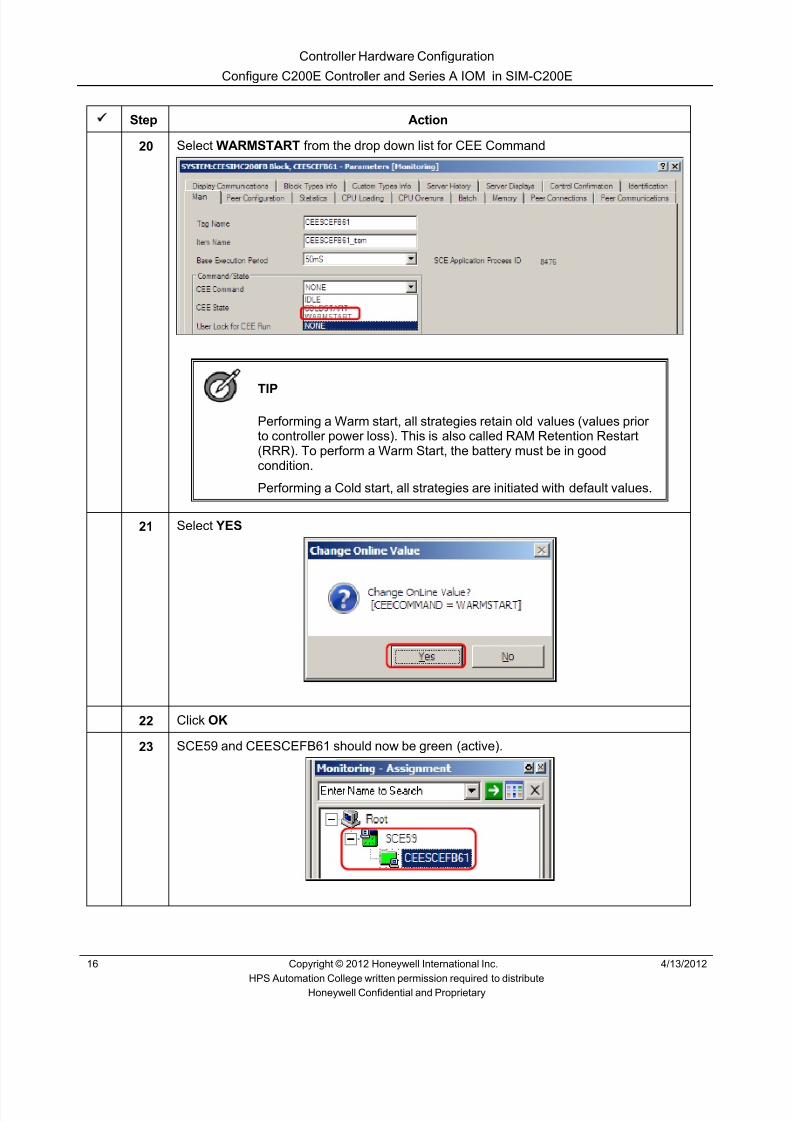
8/9/2019 Student Course Book- Automation
http://slidepdf.com/reader/full/student-course-book-automation 198/1165
Controller Hardware Configuration
Configure C200E Controller and Series A IOM in SIM-C200E
16 Copyright © 2012 Honeywell International Inc. 4/13/2012
HPS Automation College written permission required to distributeHoneywell Confidential and Proprietary
Step Action
20 Select WARMSTART from the drop down list for CEE Command
TIP
Performing a Warm start, all strategies retain old values (values priorto controller power loss). This is also called RAM Retention Restart(RRR). To perform a Warm Start, the battery must be in goodcondition.
Performing a Cold start, all strategies are initiated with default values.
21 Select YES
22 Click OK
23 SCE59 and CEESCEFB61 should now be green (active).

8/9/2019 Student Course Book- Automation
http://slidepdf.com/reader/full/student-course-book-automation 199/1165
Controller Hardware Configuration
Configure C200E Controller and Series A IOM in SIM-C200E
4/13/2012 Copyright © 2012 Honeywell International Inc. 17
HPS Automation College written permission required to distributeHoneywell Confidential and Proprietary
Configure C200E Racks and Rail I/Os
This section familiarizes you with the different types of available C200E IOMs (Input/OutputModules). Configure IOMs according to the instructions in the following steps. Use the names
provided in the lab exercise for the I/O Modules.
Step Action
1 Choose one of the following options, depending on your preference:
1. Open two Project/Monitor tree windows. On one of the windows, select theProject tab. On the other window, select the Monitoring tab
2. Open only one Project/Monitor tree window. Select the Project tab or theMonitoring tab as needed
Option 1 is shown here:
2 Return to the Project Tree Window.
Project Treewindow
Library Tree window
Monitoring Tree window

8/9/2019 Student Course Book- Automation
http://slidepdf.com/reader/full/student-course-book-automation 200/1165
Controller Hardware Configuration
Configure C200E Controller and Series A IOM in SIM-C200E
18 Copyright © 2012 Honeywell International Inc. 4/13/2012
HPS Automation College written permission required to distributeHoneywell Confidential and Proprietary
Step Action
3 Select File > New > I/O Modules > IOMODULE in the Control Builder menu.• This gives the list of all available C200E IO Modules
NOTE : The system being built will have architecture, as shown below.
BuiltManually
Imported

8/9/2019 Student Course Book- Automation
http://slidepdf.com/reader/full/student-course-book-automation 201/1165
Controller Hardware Configuration
Configure C200E Controller and Series A IOM in SIM-C200E
4/13/2012 Copyright © 2012 Honeywell International Inc. 19
HPS Automation College written permission required to distributeHoneywell Confidential and Proprietary
Step Action
4 Select TC-IAH061 – Analog Input Module, 6 Channel, 10V/ 4-20mA, Isolated .
A) Change the Module Name to AI_3_4_4 .Enter the Item Name AI_3_4_4_Item
B) Enter Module Description as “ Isolated Analog I/P in Slot 3 CNI MAC 4 ”.
C) Enter the IOM Slot Number as 3. This is the Physical slot number of the I/Omodule being configured.
D) Enter the Remote IO Chassis MAC Address as 4. This is the MAC address of theCNI Card from the I/O Rack where this IOM resides.
E) Enter ControlNet Module Slot Number as 4. This is the slot number of the CNIcard in the control rack to which the I/O chassis communicates. This value iszero for local IOMs.
A
B
C
D
E
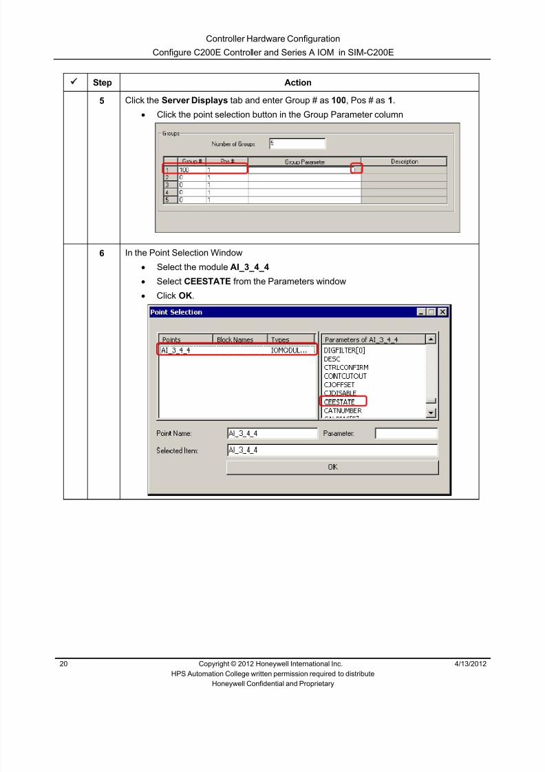
8/9/2019 Student Course Book- Automation
http://slidepdf.com/reader/full/student-course-book-automation 202/1165
Controller Hardware Configuration
Configure C200E Controller and Series A IOM in SIM-C200E
20 Copyright © 2012 Honeywell International Inc. 4/13/2012
HPS Automation College written permission required to distributeHoneywell Confidential and Proprietary
Step Action
5 Click the Server Displays tab and enter Group # as 100 , Pos # as 1.• Click the point selection button in the Group Parameter column
6 In the Point Selection Window•
Select the module AI_3_4_4 • Select CEESTATE from the Parameters window• Click OK .

8/9/2019 Student Course Book- Automation
http://slidepdf.com/reader/full/student-course-book-automation 203/1165
Controller Hardware Configuration
Configure C200E Controller and Series A IOM in SIM-C200E
4/13/2012 Copyright © 2012 Honeywell International Inc. 21
HPS Automation College written permission required to distributeHoneywell Confidential and Proprietary
Step Action
7 In the IOMODULE dialog box, click OK.

8/9/2019 Student Course Book- Automation
http://slidepdf.com/reader/full/student-course-book-automation 204/1165
Controller Hardware Configuration
Configure C200E Controller and Series A IOM in SIM-C200E
22 Copyright © 2012 Honeywell International Inc. 4/13/2012
HPS Automation College written permission required to distributeHoneywell Confidential and Proprietary
Step Action
8 Expand the Unassigned section, to view the AI module.• The module appears in the Unassigned section, as shown below.
9 Select AI_3_4_4
10Click the button on the Control Builder toolbar to assign the IOM to the SCE59controller.

8/9/2019 Student Course Book- Automation
http://slidepdf.com/reader/full/student-course-book-automation 205/1165
Controller Hardware Configuration
Configure C200E Controller and Series A IOM in SIM-C200E
4/13/2012 Copyright © 2012 Honeywell International Inc. 23
HPS Automation College written permission required to distributeHoneywell Confidential and Proprietary
Step Action
11 Select AI_3_4_4 from the ‘Available Modules’ list, select CEESCEFB61 from the ‘AssignTo’ list, and click the Assign button to assign this IOM to CEESCEFB61.
ATTENTION
Since you can have up to 20 controllers associatedwith one Experion Server, there could have beenseveral controllers (each with its own CEE) listed, inwhich case you would pick the CEE to which you wereassigning the IOM. In the lab exercise we are buildingone C200E; therefore, only one CEE will be shown inthe “Assign To” list.

8/9/2019 Student Course Book- Automation
http://slidepdf.com/reader/full/student-course-book-automation 206/1165
Controller Hardware Configuration
Configure C200E Controller and Series A IOM in SIM-C200E
24 Copyright © 2012 Honeywell International Inc. 4/13/2012
HPS Automation College written permission required to distributeHoneywell Confidential and Proprietary
Step Action
12 AI_3_4_4 is assigned to CEESCEFB61, as shown below.
13 Click Close .
14 If required, expand SCE59 and CEESCEFB61 by clicking on the buttons in theproject tab.
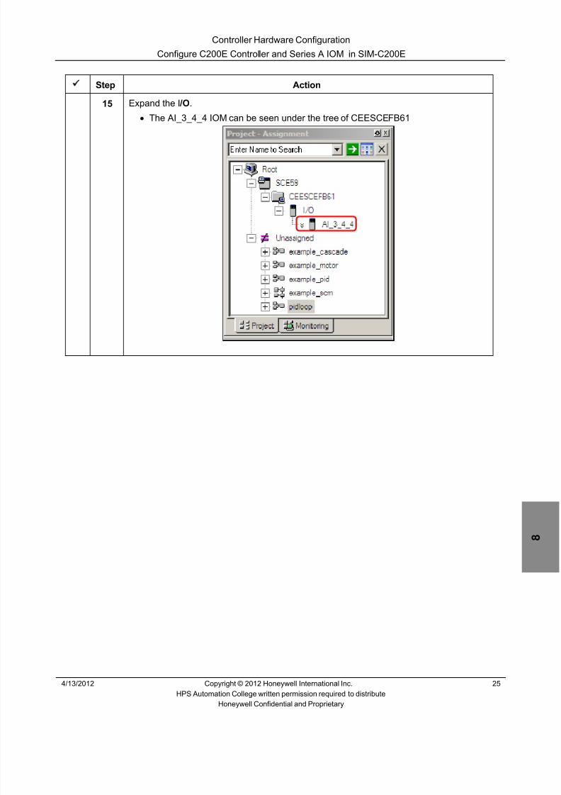
8/9/2019 Student Course Book- Automation
http://slidepdf.com/reader/full/student-course-book-automation 207/1165
Controller Hardware Configuration
Configure C200E Controller and Series A IOM in SIM-C200E
4/13/2012 Copyright © 2012 Honeywell International Inc. 25
HPS Automation College written permission required to distributeHoneywell Confidential and Proprietary
Step Action
15 Expand the I /O .• The AI_3_4_4 IOM can be seen under the tree of CEESCEFB61

8/9/2019 Student Course Book- Automation
http://slidepdf.com/reader/full/student-course-book-automation 208/1165
Controller Hardware Configuration
Configure C200E Controller and Series A IOM in SIM-C200E
26 Copyright © 2012 Honeywell International Inc. 4/13/2012
HPS Automation College written permission required to distributeHoneywell Confidential and Proprietary
Step Action
16 Add a Digital Input module.• Click File > New> I/O Modules > IOMODULE • Select the module TC-IDD321 – Digital Input, 32 ch, 24V DC • Enter the Module Name as DI_10_4_4 under the main tab• Enter the Item Name as DI_10_4_4_Item • Enter the Module Description as “ Digital Input in Slot 10 CNI MAC 4 ”

8/9/2019 Student Course Book- Automation
http://slidepdf.com/reader/full/student-course-book-automation 209/1165
Controller Hardware Configuration
Configure C200E Controller and Series A IOM in SIM-C200E
4/13/2012 Copyright © 2012 Honeywell International Inc. 27
HPS Automation College written permission required to distributeHoneywell Confidential and Proprietary
Step Action
17 Enter the I/O Rack Addresses for this IOM, as follows:• IOM Slot Number as 10 • Remote IO Chassis MAC Address as 4 • Control Net Module Slot Number (connected to I/O Chassis) as 4
18 Select the Server Displays tab.• Enter the Group # as 100 , Pos # as 6, Group Parameter as
DI_10_4_4.CEESTATE • Click OK

8/9/2019 Student Course Book- Automation
http://slidepdf.com/reader/full/student-course-book-automation 210/1165
Controller Hardware Configuration
Configure C200E Controller and Series A IOM in SIM-C200E
28 Copyright © 2012 Honeywell International Inc. 4/13/2012
HPS Automation College written permission required to distributeHoneywell Confidential and Proprietary
Step Action
19 Click the OK button, and the module DI_10_4_4 will be added in the Unassigned list, asshown below
20 Assign the DI_10_4_4 module to CEESCEFB61. Refer to the steps above, if any help isrequired
21 Verify that the DI module is now assigned to the SCE59 controller, as shown above

8/9/2019 Student Course Book- Automation
http://slidepdf.com/reader/full/student-course-book-automation 211/1165
Controller Hardware Configuration
Import the Remaining Series A IO Modules into the SCE
4/13/2012 Copyright © 2012 Honeywell International Inc. 29
HPS Automation College written permission required to distributeHoneywell Confidential and Proprietary
Import the Remaining Series A IO Modules into the SCE
Practice
Objective
• Import the remaining hardware modules
• Observe the operation of the Import/Export function
Prerequisites
• Experion PKS Server setup and configured to run an SCE controller
Introduction
• To study the Import/Export facility of Control Builder, we will import the other IOMs intothe database. Using the Import/Export functionality, you can copy/paste items from one
project to other
• A Project file can contain many items such as IOMs and CMs. From Control Builder youcan use the Import/ Export tool to copy part or all of one project to another
• “Import” copies designated function blocks from the Import/Export files located in thedirectory shown in the Import form to the Control Builder Project. In this lab we will Importthe remaining Input/Output modules into the Project. These IOMs are pre-configured,already exported and located in the following directory:
C:\Users\Public\ Public Documents\Honeywell\Experion PKS\Ixport\Student_DB\Series_A

8/9/2019 Student Course Book- Automation
http://slidepdf.com/reader/full/student-course-book-automation 212/1165
Controller Hardware Configuration
Import the Remaining Series A IO Modules into the SCE
30 Copyright © 2012 Honeywell International Inc. 4/13/2012
HPS Automation College written permission required to distributeHoneywell Confidential and Proprietary
Complete the Following Steps Using Control Builder
Step Action
1 In the Project window select File > Import to call up the import box.
• Browse to: C:\Users\Public\ Public Documents\Honeywell\Experion PKS\Ixport\Student_DB\Series_A and click OK in the ‘Choose folder’ window.
• After selecting a directory location, all the objects available for import aredisplayed in the Object list box. The following Import dialog box examplecontains only Control Modules (CMs)
ATTENTION
When the dialog box opens, the Project Tree windowcloses automatically.
Your list may be different and contain additional items.

8/9/2019 Student Course Book- Automation
http://slidepdf.com/reader/full/student-course-book-automation 213/1165
Controller Hardware Configuration
Import the Remaining Series A IO Modules into the SCE
4/13/2012 Copyright © 2012 Honeywell International Inc. 31
HPS Automation College written permission required to distributeHoneywell Confidential and Proprietary
Step Action
2 Select only the following Blocks from the Object list:
1. AI_5_4_4
2. AI_8_4_43. AO_4_4_4
4. AO_7_4_4
5. DO_6_4_4
6. DO_9_4_4
Selection can be done with the <SHIFT> button or the <CTRL> button.• Keep the option “Import CEE Assignments” selected
ATTENTION
This option imports and assigns the above items to the CEESCEFB61 .If this option is not selected, then the imported function blocks areimported as unassigned blocks. The assignment option can be usedbecause the items being imported are being assigned to the same“named” SCE/CEE from which they were exported.

8/9/2019 Student Course Book- Automation
http://slidepdf.com/reader/full/student-course-book-automation 214/1165
Controller Hardware Configuration
Import the Remaining Series A IO Modules into the SCE
32 Copyright © 2012 Honeywell International Inc. 4/13/2012
HPS Automation College written permission required to distributeHoneywell Confidential and Proprietary
Step Action
3 Click the Import button. The following dialog box will appear, indicating the status of theimport.
ATTENTION
After a successful Import, this dialog box closes.

8/9/2019 Student Course Book- Automation
http://slidepdf.com/reader/full/student-course-book-automation 215/1165
Controller Hardware Configuration
Import the Remaining Series A IO Modules into the SCE
4/13/2012 Copyright © 2012 Honeywell International Inc. 33
HPS Automation College written permission required to distributeHoneywell Confidential and Proprietary
Step Action
4 Open the Project Tree window, if not already open.
1. After importing all required modules, the I/O listed will appear similar to theillustration below
5 Press and hold the < CTRL > key and select all the I/O modules one by one.
6Click the button and download all the I/O modules.
7 Click Continue in the Load window.

8/9/2019 Student Course Book- Automation
http://slidepdf.com/reader/full/student-course-book-automation 216/1165
Controller Hardware Configuration
Import the Remaining Series A IO Modules into the SCE
34 Copyright © 2012 Honeywell International Inc. 4/13/2012
HPS Automation College written permission required to distributeHoneywell Confidential and Proprietary
Step Action
8 Verify that the checkboxes, shown below, are selected.
9 Click OK to start the download.
10 Click the Monitoring tab and verify that all the IOs are loaded and active (green).

8/9/2019 Student Course Book- Automation
http://slidepdf.com/reader/full/student-course-book-automation 217/1165
Controller Hardware Configuration
Import the Remaining Series A IO Modules into the SCE
4/13/2012 Copyright © 2012 Honeywell International Inc. 35
HPS Automation College written permission required to distributeHoneywell Confidential and Proprietary
Step Action
11 Start Station if not already open.
12 To call the Group display, press <F6> and enter 100 in the message zone.
13 Click OK .
1. The status of all IO modules is displayed.

8/9/2019 Student Course Book- Automation
http://slidepdf.com/reader/full/student-course-book-automation 218/1165
Controller Hardware Configuration
Import the Remaining Series A IO Modules into the SCE
36 Copyright © 2012 Honeywell International Inc. 4/13/2012
HPS Automation College written permission required to distributeHoneywell Confidential and Proprietary
This page was intentionally left blank.

8/9/2019 Student Course Book- Automation
http://slidepdf.com/reader/full/student-course-book-automation 219/1165
Controller Hardware Configuration
Configure C300 Controller and Series C IOM in SIM-C300
4/13/2012 Copyright © 2012 Honeywell International Inc. 37
HPS Automation College written permission required to distributeHoneywell Confidential and Proprietary
Configure C300 Controller and Series C IOM in SIM-C300
Practice
Introduction
In this lab, you will learn how to configure a simulated C300, referred to as a SIM-C300. The SIM-C300 supports full simulation of the C300 controller including load and execution of all function
blocks supported by the C300 controller, a CEE executing with the same base execution cycles, blocks executing with the same block execution period selections, and interaction with Series C I/Oand PM I/O .
Objective
• Configure a SIM-C300 Controller in Control Builder• Configure a SIM-C300 CEE in Control Builder• Configure the 2 IOLINKs• Configure Series C IOM• Download and activate the SIM-C300, CEE, and IOM• Verify online SIM-C300 controller in Control Builder• Verify online SIM-C300 CEE Statistics in Control Builder

8/9/2019 Student Course Book- Automation
http://slidepdf.com/reader/full/student-course-book-automation 220/1165
Controller Hardware Configuration
Configure C300 Controller and Series C IOM in SIM-C300
38 Copyright © 2012 Honeywell International Inc. 4/13/2012
HPS Automation College written permission required to distributeHoneywell Confidential and Proprietary
Procedure
Complete the Following Steps in Control Builder
Add a New SIM-C300 Controller
Step Action
1 Open the Control Builder if not opened.
2 Click File New Controllers C300 – Controller (2 I/O Links)
ATTENTION
C300 and SIM-C300 share the same template

8/9/2019 Student Course Book- Automation
http://slidepdf.com/reader/full/student-course-book-automation 221/1165
Controller Hardware Configuration
Configure C300 Controller and Series C IOM in SIM-C300
4/13/2012 Copyright © 2012 Honeywell International Inc. 39
HPS Automation College written permission required to distributeHoneywell Confidential and Proprietary
Step Action
3 Enter the Data for each configuration parameter as shown below.
The figure shows the configuration for SIM-C300 controller.
Name – Enter the name as SIM_C300
Item Name - Enter SIM_C300Item
Select the check box option “ Load to simulation Environment ”
Host Name – Simulation node name
ATTENTION
Enter the Host Name of your Experion Server andpress Enter. The Host IP Address shouldautomatically be entered. If it is not, get the IPaddress from your course manager.

8/9/2019 Student Course Book- Automation
http://slidepdf.com/reader/full/student-course-book-automation 222/1165
Controller Hardware Configuration
Configure C300 Controller and Series C IOM in SIM-C300
40 Copyright © 2012 Honeywell International Inc. 4/13/2012
HPS Automation College written permission required to distributeHoneywell Confidential and Proprietary
Step Action
4 Keep all the other settings as default.
5 Click the OK .
6
ATTENTION
The following ‘Form Validation’ error is expected. Fora SIM C300, a device index is not necessary, and wasnot entered. On a real C300, it would have beennecessary to enter a device index.
Click “Close ” on “Form Validation ” screen
7 Double click the CEE to open Module Properties.

8/9/2019 Student Course Book- Automation
http://slidepdf.com/reader/full/student-course-book-automation 223/1165
Controller Hardware Configuration
Configure C300 Controller and Series C IOM in SIM-C300
4/13/2012 Copyright © 2012 Honeywell International Inc. 41
HPS Automation College written permission required to distributeHoneywell Confidential and Proprietary
Step Action
8 Change the name to SIM_CEEC300 , and change the Item Name to SIM_CEEC300Item .Keep all the other settings as default and Click OK
9 Double click the first IOLINK to open Module Properties.

8/9/2019 Student Course Book- Automation
http://slidepdf.com/reader/full/student-course-book-automation 224/1165
Controller Hardware Configuration
Configure C300 Controller and Series C IOM in SIM-C300
42 Copyright © 2012 Honeywell International Inc. 4/13/2012
HPS Automation College written permission required to distributeHoneywell Confidential and Proprietary
Step Action
10 Change the name to Series_C_IOLINK , and change the Item Name toSeries_C_IOLINKItem .
Select the I/O family as SERIES _C_IO_TYPE. Keep all other settings as default and
Click OK .
11 Double click second IOLINK to open Module Properties.
12 Change the name to PMIO_IOLINK , and change the Item Name to PMIO_IOLINKItem .
Select the IO family as PM_IO_TYPE. Keep all other settings as default and Click OK .
ATTENTION
This PMIO Link configuration is required to be done inclass for PM IOP configuration on the last day of thiscourse as part of optional PMIO Lesson.

8/9/2019 Student Course Book- Automation
http://slidepdf.com/reader/full/student-course-book-automation 225/1165
Controller Hardware Configuration
Configure C300 Controller and Series C IOM in SIM-C300
4/13/2012 Copyright © 2012 Honeywell International Inc. 43
HPS Automation College written permission required to distributeHoneywell Confidential and Proprietary
Step Action
Configure IO Modules for Series C IO.
13 Click File New I/O Modules Series_C _IO AI-HL High Level Analog Input

8/9/2019 Student Course Book- Automation
http://slidepdf.com/reader/full/student-course-book-automation 226/1165
Controller Hardware Configuration
Configure C300 Controller and Series C IOM in SIM-C300
44 Copyright © 2012 Honeywell International Inc. 4/13/2012
HPS Automation College written permission required to distributeHoneywell Confidential and Proprietary
Step Action
14 Tag Name – Enter the name as C_AI_1
Item Name - Enter C_AI_1_Item
IOM Number - 1.
Keep all other settings as default and click OK .
15 Configure a Series C type Digital Input module - DI-HV- High Voltage digital Input, 32channels
Tag Name – Enter the name as C_DI_6
Item Name - Enter C_DI_6_Item
IOM Number – 6
Keep all other settings as default and click OK .
16 Assign C_AI_1 and C_DI_6 to Series_C_IOLINK.
17 Select SIM_C300 in Project tree.
18Click on icon on the control builder tool bar to download the SIM-C300.
19 Click Continue , and click OK in the Load Dialog window.
20 Click the Monitoring tab and note that SIM_C300 blocks appear with “S” and it is blueindicating that it is loaded, but is not active.

8/9/2019 Student Course Book- Automation
http://slidepdf.com/reader/full/student-course-book-automation 227/1165
Controller Hardware Configuration
Configure C300 Controller and Series C IOM in SIM-C300
4/13/2012 Copyright © 2012 Honeywell International Inc. 45
HPS Automation College written permission required to distributeHoneywell Confidential and Proprietary
Step Action
21 Right-click SIM_CEEC300 and select Change State. This will open Request ValueChange dialog box
22 Select the CEE Command WARMSTART , and s elect Yes when prompted for ChangeOnline Value

8/9/2019 Student Course Book- Automation
http://slidepdf.com/reader/full/student-course-book-automation 228/1165
Controller Hardware Configuration
Configure C300 Controller and Series C IOM in SIM-C300
46 Copyright © 2012 Honeywell International Inc. 4/13/2012
HPS Automation College written permission required to distributeHoneywell Confidential and Proprietary
Step Action
23
ATTENTION
The IOLINKs do not contain IOMs, so you have to loadIOMs separately.
Click on one of the IOMs in the Project window and click on the icon on the ControlBuilder tool bar to download the IOM.
24 Download both C_AI_1 and C_DI_6
25 Click the Monitoring tab. IOMs appear in blue indicating as loaded and inactive
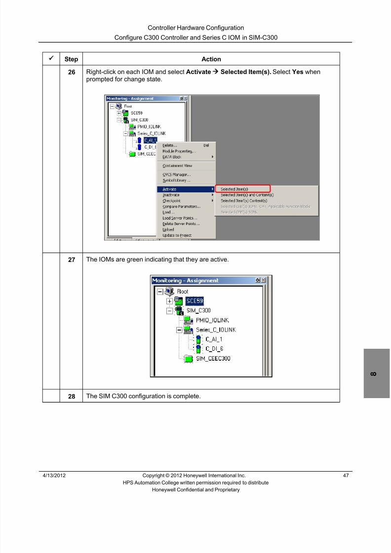
8/9/2019 Student Course Book- Automation
http://slidepdf.com/reader/full/student-course-book-automation 229/1165
Controller Hardware Configuration
Configure C300 Controller and Series C IOM in SIM-C300
4/13/2012 Copyright © 2012 Honeywell International Inc. 47
HPS Automation College written permission required to distributeHoneywell Confidential and Proprietary
Step Action
26 Right-click on each IOM and select Activate Selected Item(s). Select Yes whenprompted for change state.
27 The IOMs are green indicating that they are active.
28 The SIM C300 configuration is complete.

8/9/2019 Student Course Book- Automation
http://slidepdf.com/reader/full/student-course-book-automation 230/1165
Controller Hardware Configuration
Configure C300 Controller and Series C IOM in SIM-C300
48 Copyright © 2012 Honeywell International Inc. 4/13/2012
HPS Automation College written permission required to distributeHoneywell Confidential and Proprietary
This page was intentionally left blank.

8/9/2019 Student Course Book- Automation
http://slidepdf.com/reader/full/student-course-book-automation 231/1165
Controller Hardware Configuration
Import the Remaining Series C IO in to SIM-C300
4/13/2012 Copyright © 2012 Honeywell International Inc. 49
HPS Automation College written permission required to distributeHoneywell Confidential and Proprietary
Import the Remaining Series C IO in to SIM-C300
Practice
Objective
• Import the remaining hardware modules.
• Observe the operation of the Import/Export function.
Prerequisites
• Experion PKS Server setup and configured to run an C300/SIM C300 controller.
Introduction
• To study the Import/Export facility of Control Builder, we will import the other IOMs tocreate in the database. Using the Import/Export functionality, you can copy/paste items fromone project to other.
• A Project file can contain many items such as IOMs and CMs. From Control Builder youcan use the Import/ Export tool to copy part or all of one project to another.
• “Import” copies designated function blocks from the Import/Export files located in thedirectory shown in the Import form to the Control Builder Project. In this lab we will Importthe remaining Input/Output modules into the Project. These IOMs are pre-configured,already exported and located in the following directory:
C:\Users\Public\Public Documents\Honeywell\Experion PKS\IXPORT\Student_DB\Series_C
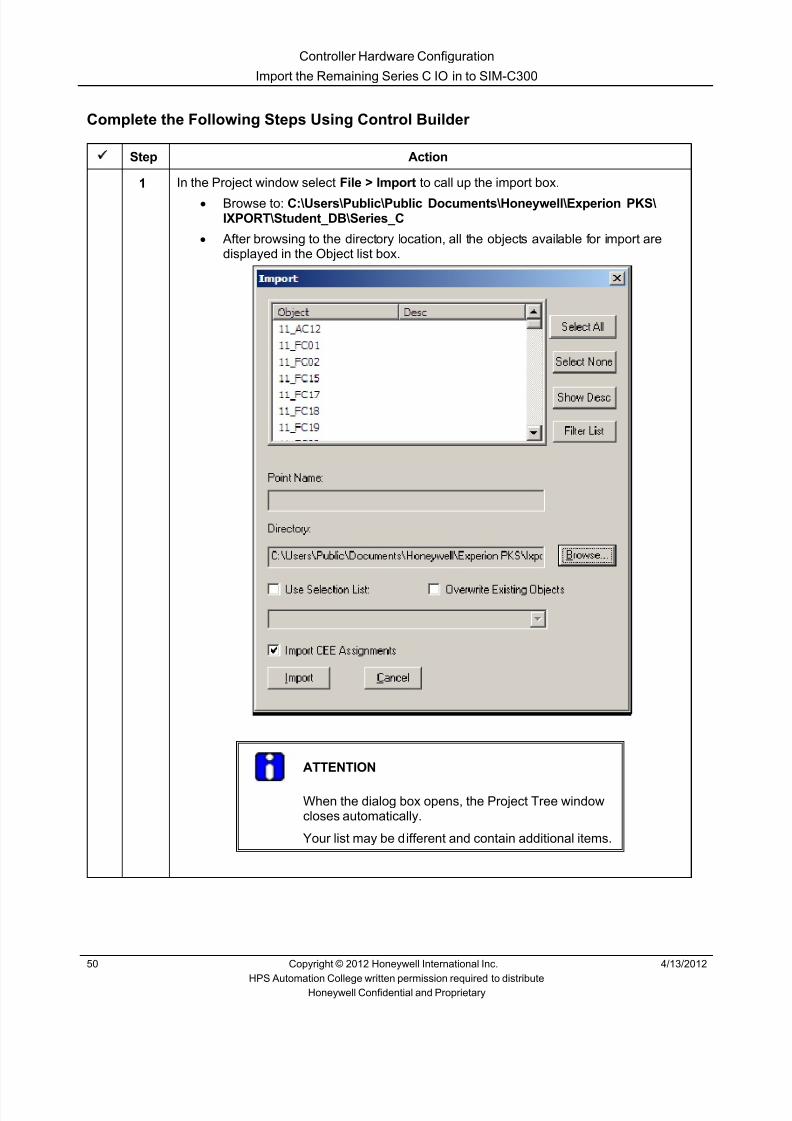
8/9/2019 Student Course Book- Automation
http://slidepdf.com/reader/full/student-course-book-automation 232/1165
Controller Hardware Configuration
Import the Remaining Series C IO in to SIM-C300
50 Copyright © 2012 Honeywell International Inc. 4/13/2012
HPS Automation College written permission required to distributeHoneywell Confidential and Proprietary
Complete the Following Steps Using Control Builder
Step Action
1 In the Project window select File > Import to call up the import box.• Browse to: C:\Users\Public\Public Documents\Honeywell\Experion PKS\
IXPORT\Student_DB\Series_C• After browsing to the directory location, all the objects available for import are
displayed in the Object list box.
ATTENTION
When the dialog box opens, the Project Tree windowcloses automatically.
Your list may be different and contain additional items.
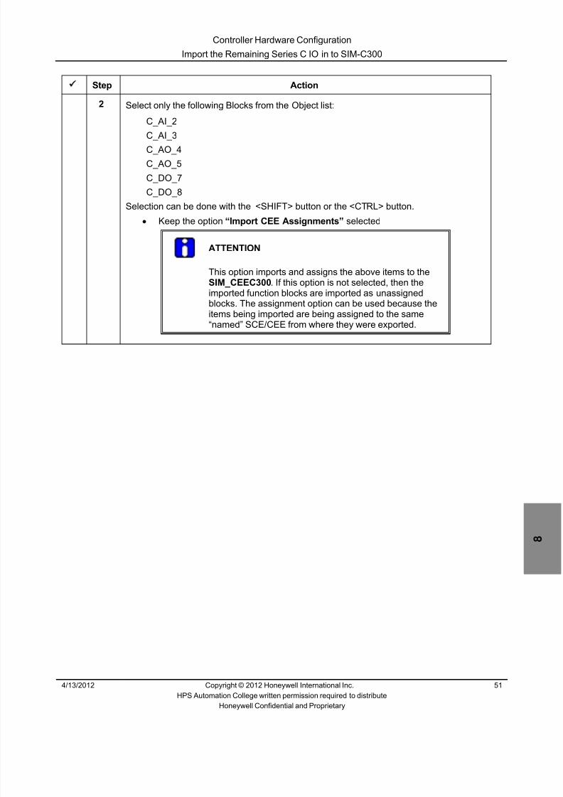
8/9/2019 Student Course Book- Automation
http://slidepdf.com/reader/full/student-course-book-automation 233/1165
Controller Hardware Configuration
Import the Remaining Series C IO in to SIM-C300
4/13/2012 Copyright © 2012 Honeywell International Inc. 51
HPS Automation College written permission required to distributeHoneywell Confidential and Proprietary
Step Action
2 Select only the following Blocks from the Object list:
C_AI_2
C_AI_3C_AO_4
C_AO_5
C_DO_7
C_DO_8
Selection can be done with the <SHIFT> button or the <CTRL> button.• Keep the option “Import CEE Assignments” selected
ATTENTION
This option imports and assigns the above items to theSIM_CEEC300 . If this option is not selected, then theimported function blocks are imported as unassignedblocks. The assignment option can be used because theitems being imported are being assigned to the same“named” SCE/CEE from where they were exported.

8/9/2019 Student Course Book- Automation
http://slidepdf.com/reader/full/student-course-book-automation 234/1165
Controller Hardware Configuration
Import the Remaining Series C IO in to SIM-C300
52 Copyright © 2012 Honeywell International Inc. 4/13/2012
HPS Automation College written permission required to distributeHoneywell Confidential and Proprietary
Step Action
3 Click the Import button. The following dialog box will appear, indicating the status of theimport.
ATTENTION
After a successful Import, this dialog box closes.

8/9/2019 Student Course Book- Automation
http://slidepdf.com/reader/full/student-course-book-automation 235/1165
Controller Hardware Configuration
Import the Remaining Series C IO in to SIM-C300
4/13/2012 Copyright © 2012 Honeywell International Inc. 53
HPS Automation College written permission required to distributeHoneywell Confidential and Proprietary
Step Action
4 Open the Project Tree window, if not already open.
1. After importing all required modules, the I/O listed will appear similar to theillustration below
5 Press and hold the < CTRL > key and select all the I/O modules which have not yet beendownloaded.
6Click the button and download all the I/O modules to the database.
7 Click Continue in the Load window.

8/9/2019 Student Course Book- Automation
http://slidepdf.com/reader/full/student-course-book-automation 236/1165
Controller Hardware Configuration
Import the Remaining Series C IO in to SIM-C300
54 Copyright © 2012 Honeywell International Inc. 4/13/2012
HPS Automation College written permission required to distributeHoneywell Confidential and Proprietary
Step Action
8 Verify that the checkboxes, shown below, are selected.
9 Click OK to start the download.
10 Click Continue if a Warning message is displayed.
11 Click the Monitoring tab and verify that all the IOs are loaded and active (green).

8/9/2019 Student Course Book- Automation
http://slidepdf.com/reader/full/student-course-book-automation 237/1165
1
1
Honeywell ConfidentialCopyright © 2012 Honeywell International Inc.
4/13/2012
Describe Fiber Optic Extender and ItsConnection Rules
C300 Controller Architecture - Part 2 of 2 Describe Fiber Optic Extender and Its Connection RulesC300 Controller Architecture - Part 2 of 2 Describe Fiber Optic Extender and Its Connection Rules
Honeywell
Honeywell ConfidentialCopyright © 2012 Honeywell International Inc.
4/13/20122
• Overview• Series C I/O Link Fiber Optic Extender Module• Topology – Series C IOM, PM IOP• Topology Type – Daisy Chain, Star, Tree• Distance Limitation• Cabinet Layout• Specifications
Topics
C300 Controller Architecture - Part 2 of 2 Describe Fiber Optic Extender and Its Connection Rules

8/9/2019 Student Course Book- Automation
http://slidepdf.com/reader/full/student-course-book-automation 238/1165
2
Honeywell
Honeywell ConfidentialCopyright © 2012 Honeywell International Inc.
4/13/20123
Overview
• The C300 controller can now be connected remotely to Series C I/O orPMIO through the use of an I/O Link Fiber Optic Extender (FOE)module.
• The same FOE cannot be used for Series C and PMIO connectionsconcurrently
• Each FOE can connect to two remote sites: – Two fiber optic ports sets, FO1 and FO2 – Ports have both receive (Rx) and transmit (Tx)
• Mounting options: – IOTA – Din Rail – Stand Alone
C300 Controller Architecture - Part 2 of 2 Describe Fiber Optic Extender and Its Connection Rules
Honeywell
Honeywell ConfidentialCopyright © 2012 Honeywell International Inc.
4/13/20124
Series C I/O Link Fiber Optic Extender Module
IOLINK cable
COMMON
Fiber OpticExtender IOTA
LED Indicators
24V DC
CarrierMounting
Screws
Fuse
FOE to IOTAMounting Screw FOE to IOTA
powerconnection
Fiber Opticports
I/O LinkConnector
C300 Controller Architecture - Part 2 of 2 Describe Fiber Optic Extender and Its Connection Rules
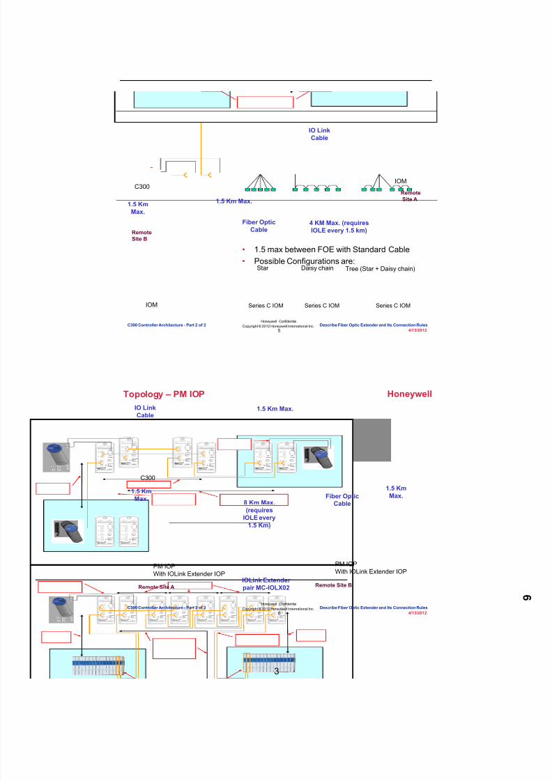
8/9/2019 Student Course Book- Automation
http://slidepdf.com/reader/full/student-course-book-automation 239/1165
3
Honeywell
Honeywell ConfidentialCopyright © 2012 Honeywell International Inc.
4/13/20125
Topology – Series C IOM
Star
Series C IOM
Daisy chain
Series C IOM
Tree (Star + Daisy chain)
Series C IOM
• 1.5 max between FOE with Standard Cable• Possible Configurations are:
C300
IOM
IOM
RemoteSite A
RemoteSite B
1.5 KmMax.
1.5 Km Max.
4 KM Max. (requiresIOLE every 1.5 km)
Fiber OpticCable
IO LinkCable
C300 Controller Architecture - Part 2 of 2 Describe Fiber Optic Extender and Its Connection Rules
Honeywell
Honeywell ConfidentialCopyright © 2012 Honeywell International Inc.
4/13/20126
Topology – PM IOP
C300
PM IOPWith IOLink Extender IOP
Remote Site BRemote Site A
PM IOPWith IOLink Extender IOP
1.5 Km Max.
1.5 KmMax.
8 Km Max.(requires
IOLE every1.5 Km)
1.5 KmMax.
IOLink Extenderpair MC-IOLX02
Fiber OpticCable
IO LinkCable
C300 Controller Architecture - Part 2 of 2 Describe Fiber Optic Extender and Its Connection Rules

8/9/2019 Student Course Book- Automation
http://slidepdf.com/reader/full/student-course-book-automation 240/1165
4
Honeywell
Honeywell ConfidentialCopyright © 2012 Honeywell International Inc.
4/13/20127
Topology Type – Daisy Chain
RemoteSite 2
FOE
IOM
Fiber Optic
Cable
IO LinkCable
RemoteSite 1
MainLocation
C300
C300 Controller Architecture - Part 2 of 2 Describe Fiber Optic Extender and Its Connection Rules
Honeywell
Honeywell ConfidentialCopyright © 2012 Honeywell International Inc.
4/13/20128
Topology Type – Star
• It is possible to have multiple fiber-optic extenders in any location, provided distancelimitations are observed and no more than 40 IOMs are on a single I/O Link.
RemoteSite 1
RemoteSite 2
RemoteSite 3
RemoteSite 4
FOE
Fiber OpticCable
IO LinkCable
MainLocation
IOM
C300 Controller Architecture - Part 2 of 2 Describe Fiber Optic Extender and Its Connection Rules

8/9/2019 Student Course Book- Automation
http://slidepdf.com/reader/full/student-course-book-automation 241/1165
5
Honeywell
Honeywell ConfidentialCopyright © 2012 Honeywell International Inc.
4/13/20129
Topology Type – Tree
IOM
IOM
FOE
Fiber OpticCable
IO LinkCable
Fiber1
Fiber2
Fiber3
Fiber1
Fiber2
Fiber3RemoteSite 2
RemoteSite 1
MainLocation
C300
C300 Controller Architecture - Part 2 of 2 Describe Fiber Optic Extender and Its Connection Rules
Honeywell
Honeywell ConfidentialCopyright © 2012 Honeywell International Inc.
4/13/201210
Distance Limitations with Series C
• Maximum distance of any single fiber-optic segment must be less than 1.5 km:d1, d2, d3, d4 <= 1.5 km
• Maximum distance of any single “leg” must be less than 4.0 km. In above figure:0.25 + d1 + 0.25 <= 4.0 km0.25 + d2 + 0.25 + d3 + 0.25 + d4 + 0.25 <= 4.0 km
MainLocation
RemoteSite#2
RemoteSite#3
RemoteSite#4
RemoteSite#1d1
d2
d3d4
IOM IOM
IOM
IOM
C300
IOM
C300 Controller Architecture - Part 2 of 2 Describe Fiber Optic Extender and Its Connection Rules
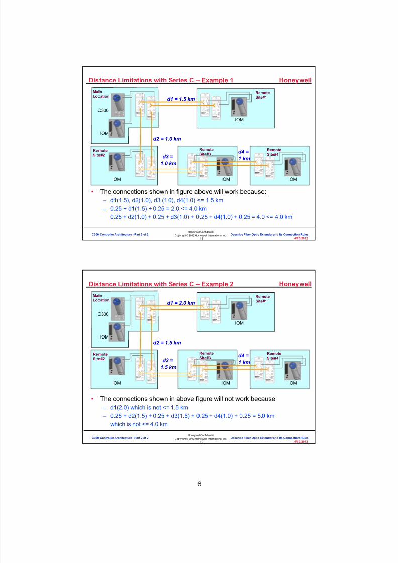
8/9/2019 Student Course Book- Automation
http://slidepdf.com/reader/full/student-course-book-automation 242/1165
6
Honeywell
Honeywell ConfidentialCopyright © 2012 Honeywell International Inc.
4/13/201211
Distance Limitations with Series C – Example 1
• The connections shown in figure above will work because: – d1(1.5), d2(1.0), d3 (1.0), d4(1.0) <= 1.5 km – 0.25 + d1(1.5) + 0.25 = 2.0 <= 4.0 km
0.25 + d2(1.0) + 0.25 + d3(1.0) + 0.25 + d4(1.0) + 0.25 = 4.0 <= 4.0 km
Main
Location
RemoteSite#2
RemoteSite#3
RemoteSite#4
Remote
Site#1
IOM IOM
IOM
IOM
C300
IOM
d1 = 1.5 km
d2 = 1.0 km
d3 =1.0 km
d4 =1 km
C300 Controller Architecture - Part 2 of 2 Describe Fiber Optic Extender and Its Connection Rules
Honeywell
Honeywell ConfidentialCopyright © 2012 Honeywell International Inc.
4/13/201212
Distance Limitations with Series C – Example 2
• The connections shown in above figure will not work because: – d1(2.0) which is not <= 1.5 km – 0.25 + d2(1.5) + 0.25 + d3(1.5) + 0.25 + d4(1.0) + 0.25 = 5.0 km
which is not <= 4.0 km
MainLocation
RemoteSite#2
RemoteSite#3
RemoteSite#4
RemoteSite#1
IOM IOM
IOM
IOM
C300
IOM
d1 = 2.0 km
d2 = 1.5 km
d3 =1.5 km
d4 =1 km
C300 Controller Architecture - Part 2 of 2 Describe Fiber Optic Extender and Its Connection Rules

8/9/2019 Student Course Book- Automation
http://slidepdf.com/reader/full/student-course-book-automation 243/1165
7
Honeywell
Honeywell ConfidentialCopyright © 2012 Honeywell International Inc.
4/13/201213
Cabinet Layout
FOE – AI/O Link
Extender forLink A
FOE – BI/O Link
Extender forLink B
FOE can useeither Violetor Grey IOL
C300Controller
ControlFirewall
Digital InputCard
C300 Controller Architecture - Part 2 of 2 Describe Fiber Optic Extender and Its Connection Rules
Honeywell
Honeywell ConfidentialCopyright © 2012 Honeywell International Inc.
4/13/201214
Specifications• Power Supply Options
– 20 to 30V @ 200mA• Distance
– Segment distance between FOE:• With Standard Cable: 1.5 Km• With Premium Cable: 2.0 Km
– Total maximum IOLink length• Series C IO: 4 Km• PM IO: 8 Km
– Propagation delay: Each FOE fiber optic converter subtracts a certain value from thetotal IOLink length.
• Series C IO: 0.25 Km per FOE• PM IO: 0.5 Km per FOE
• Fiber-Optic – Fiber type: Multimode – Fiber core diameter: 62.5 mm – Fiber cladding diameter: 125 mm – Fiber connectors: ST type – Power budget: 8 db min, 15 db typical
C300 Controller Architecture - Part 2 of 2 Describe Fiber Optic Extender and Its Connection Rules

8/9/2019 Student Course Book- Automation
http://slidepdf.com/reader/full/student-course-book-automation 244/1165
8
Honeywell
Honeywell ConfidentialCopyright © 2012 Honeywell International Inc.
4/13/201215
Describe the Fiber Optic Extender and Its ConnectionRules
CompletionCertificate
Proceed to the next lesson in your course material.
C300 Controller Architecture - Part 2 of 2 Describe Fiber Optic Extender and Its Connection Rules
Honeywell
Honeywell ConfidentialCopyright © 2012 Honeywell International Inc.
4/13/201216
This page intentionally left blank
C300 Controller Architecture - Part 2 of 2 Describe Fiber Optic Extender and Its Connection Rules

8/9/2019 Student Course Book- Automation
http://slidepdf.com/reader/full/student-course-book-automation 245/1165
9
17
Honeywell ConfidentialCopyright © 2012 Honeywell International Inc.
4/13/2012
Describe the Control Firewall Connections inthe Series C System
C300 Controller Architecture - Part 2 of 2 Describe the Control Firewall Connections in the Series C SystemC300 Controller Architecture - Part 2 of 2 Describe the Control Firewall Connections in the Series C System
Honeywell
Honeywell ConfidentialCopyright © 2012 Honeywell International Inc.
4/13/201218
Overview
• Topology rules pertaining to the Control Firewall
• Overview of FTE limits
C300 Controller Architecture - Part 2 of 2 Describe the Control Firewall Connections in the Series C System

8/9/2019 Student Course Book- Automation
http://slidepdf.com/reader/full/student-course-book-automation 246/1165
10
Honeywell
Honeywell ConfidentialCopyright © 2012 Honeywell International Inc.
4/13/201219
C300 Topology Rules – Control Firewall
C300, Series C FIMs must be connected to the ControlFirewall.
The C300 and any FTEBs assigned to it must be on the samecontrol firewall.
No other device , such as FTEB for C200, Ethernet PLCs,Stations or Servers can connect to the Control Firewall with theexception of devices qualified for Peer Control Data Interf acelike Safety Manager and Modbus Gateway’s (Explained in
Advance Course).
C300 Controller Architecture - Part 2 of 2 Describe the Control Firewall Connections in the Series C System
Honeywell
Honeywell ConfidentialCopyright © 2012 Honeywell International Inc.
4/13/201220
C300 Topology Rules – Control Firewall
The Control Firewall is connected by uplink to a L1 orL2 switch. Connections can be Fiber Optic or STPCable.
Fiber Optic: 2 KM multi mode or 15 KM single mode.STP cable: CAT 5 up to 100 M.
Control Firewalls cannot be cascaded.
C300 Controller Architecture - Part 2 of 2 Describe the Control Firewall Connections in the Series C System

8/9/2019 Student Course Book- Automation
http://slidepdf.com/reader/full/student-course-book-automation 247/1165
11
Honeywell
Honeywell ConfidentialCopyright © 2012 Honeywell International Inc.
4/13/201221
Wiring Detail – Series C Control Firewall
FTE Yellow/A
FTE Green/B
STP Uplink
Fiber Uplink
C300 Controller Architecture - Part 2 of 2 Describe the Control Firewall Connections in the Series C System
Honeywell
Honeywell ConfidentialCopyright © 2012 Honeywell International Inc.
4/13/201222
Series C Control Firewall
100Base-FXUplink
(Media Converter not shown)
100Base-TXUplink
10/100Base-TXPorts
Control FirewallModule
C300 Controller Architecture - Part 2 of 2 Describe the Control Firewall Connections in the Series C System

8/9/2019 Student Course Book- Automation
http://slidepdf.com/reader/full/student-course-book-automation 248/1165
12
Honeywell
Honeywell ConfidentialCopyright © 2012 Honeywell International Inc.
4/13/201223
Series C Control Firewall Module
• Diagnostic LEDs• 24VDC Power Present• Status/Alarm LED (bicolor -
blink when the alarmoccurs)
• Activity LEDs for all ports
Activity LEDsfor Ports
C300 Controller Architecture - Part 2 of 2 Describe the Control Firewall Connections in the Series C System
Honeywell
Honeywell ConfidentialCopyright © 2012 Honeywell International Inc.
4/13/201224
How Many FTE Nodes Do You Have?
• An FTE Community can have no more than 330 FTE Nodes calculatedas follows:
– Max. 125 Redundant FIMs per Server = 125 x 2 = 250
– Max. 20 Redundant C300s per Server = 20 x 2 = 40
– Max. 2 Redundant PGMs per Server = 2 x 2 = 4
– Max. 40 Stations = 40
– Max. 1 Redundant Server Pair = 2
– Max. 7 ACE = 7
– GRAND TOTAL: 343
• If any FTEBs are present in the Community, the limit is 200 FTE Nodes.
• “Embedded FTE” which is used in the C300, Series C FIM, and PGM isat the MAC layer; therefore, “yellow” and “green” have same IP address.
• Starting in R400, Servers and Workstations require only one IP address.
C300 Controller Architecture - Part 2 of 2 Describe the Control Firewall Connections in the Series C System
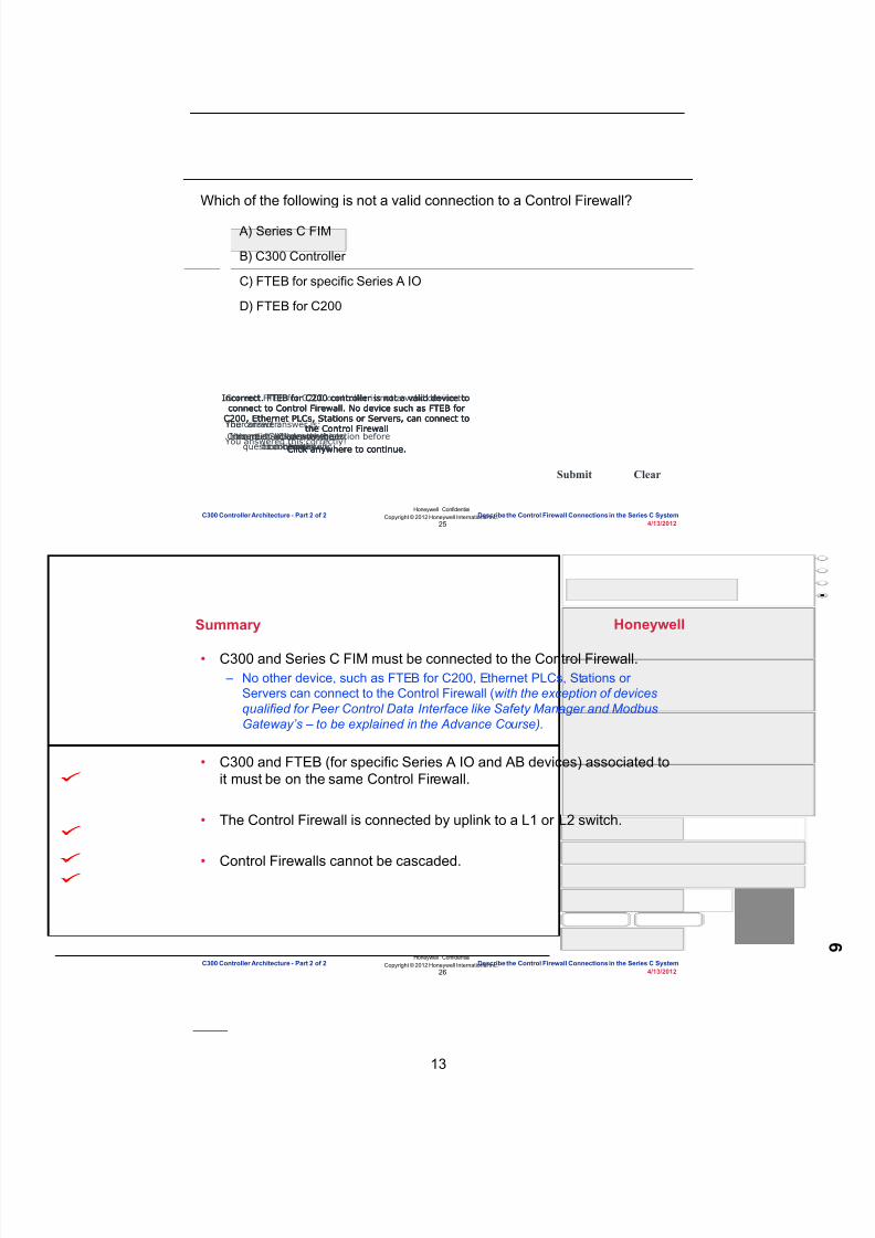
8/9/2019 Student Course Book- Automation
http://slidepdf.com/reader/full/student-course-book-automation 249/1165
13
Honeywell
Honeywell ConfidentialCopyright © 2012 Honeywell International Inc.
4/13/201225
Question 1: Control Firewall
Correct - Click anywhere tocontinue
Incorrect - Click anywhereto continueYou answered this correctly!
Your answer:The correct answer is:You did not answer this
question completelyYou must answer the question before
continuing
Submit Clear
Incorrect. FTEB for C200 controller is not a valid device toconnect to Control Firewall. No device such as FTEB for
C200, Ethernet PLCs, Stations or Servers, can connect tothe Control Firewall
Click anywhere to continue.
Incorrect. FTEB for C200 controller is not a valid device toconnect to Control Firewall. No device such as FTEB for
C200, Ethernet PLCs, Stations or Servers, can connect tothe Control Firewall
Click anywhere to continue.
Incorrect. FTEB for C200 controller is not a valid device toconnect to Control Firewall. No device such as FTEB for
C200, Ethernet PLCs, Stations or Servers, can connect tothe Control Firewall
Click anywhere to continue.
Correct! FTEB for C200 controller is not a valid device toconnect to Control Firewall. No device such as FTEB for
C200, Ethernet PLCs, Stations or Servers, can connect tothe Control Firewall
Click anywhere to continue.
Which of the following is not a valid connection to a Control Firewall?
A) Series C FIM
B) C300 Controller
C) FTEB for specific Series A IO
D) FTEB for C200
C300 Controller Architecture - Part 2 of 2 Describe the Control Firewall Connections in the Series C System
Honeywell
Honeywell ConfidentialCopyright © 2012 Honeywell International Inc.
4/13/201226
Summary
• C300 and Series C FIM must be connected to the Control Firewall. – No other device, such as FTEB for C200, Ethernet PLCs, Stations or
Servers can connect to the Control Firewall ( with the exception of devicesqualified for Peer Control Data Interface like Safety Manager and ModbusGateway’s – to be explained in the Advance Course).
• C300 and FTEB (for specific Series A IO and AB devices) associated toit must be on the same Control Firewall.
• The Control Firewall is connected by uplink to a L1 or L2 switch.
• Control Firewalls cannot be cascaded.
C300 Controller Architecture - Part 2 of 2 Describe the Control Firewall Connections in the Series C System

8/9/2019 Student Course Book- Automation
http://slidepdf.com/reader/full/student-course-book-automation 250/1165
14
Honeywell
Honeywell ConfidentialCopyright © 2012 Honeywell International Inc.
4/13/201227
Describe the Control Firewall connections in theSeries C System
CompletionCertificate
Proceed to the next lesson in your course material.
C300 Controller Architecture - Part 2 of 2 Describe the Control Firewall Connections in the Series C System
Honeywell
Honeywell ConfidentialCopyright © 2012 Honeywell International Inc.
4/13/201228
This page intentionally left blank
C300 Controller Architecture - Part 2 of 2 Describe the Control Firewall Connections in the Series C System

8/9/2019 Student Course Book- Automation
http://slidepdf.com/reader/full/student-course-book-automation 251/1165
15
29
Honeywell ConfidentialCopyright © 2012 Honeywell International Inc.
4/13/2012
Define a Typical Series C Configuration
C300 Controller Architecture - Part 2 of 2 Define a Typical Series C ConfigurationC300 Controller Architecture - Part 2 of 2 Define a Typical Series C Configuration
Honeywell
Honeywell ConfidentialCopyright © 2012 Honeywell International Inc.
4/13/201230
Putting the Pieces Together
CF9
RED
C300 FIM
RED
FIM
Series C IO
PMIO
Series A IO
C300 Controller Architecture - Part 2 of 2 Define a Typical Series C Configuration

8/9/2019 Student Course Book- Automation
http://slidepdf.com/reader/full/student-course-book-automation 252/1165
16
Honeywell
Honeywell ConfidentialCopyright © 2012 Honeywell International Inc.
4/13/201231
C300 Controller I/O Link Configurations
FTE Yellow and Green
IOLINK 1 and 2
C300 Controller Architecture - Part 2 of 2 Define a Typical Series C Configuration
Honeywell
Honeywell ConfidentialCopyright © 2012 Honeywell International Inc.
4/13/201232
How a Cabinet is Wired
Typical I/O Link Cable
C300 Controller Architecture - Part 2 of 2 Define a Typical Series C Configuration

8/9/2019 Student Course Book- Automation
http://slidepdf.com/reader/full/student-course-book-automation 253/1165
17
Honeywell
Honeywell ConfidentialCopyright © 2012 Honeywell International Inc.
4/13/201233
Series C C300 Controller
IOTA
Battery connectionfrom power system
Private pathredundancy (shielded
Twisted pair)
FTE
I/O Link # 2
C300 ControllerModule
I/O Link # 1
GPS Time Sync Input(Future)
FTE Deviceindex
C300 Controller Architecture - Part 2 of 2 Define a Typical Series C Configuration
Honeywell
Honeywell ConfidentialCopyright © 2012 Honeywell International Inc.
4/13/201234
Wiring Detail – Series C FIM
Fieldbus Links
Connection toFieldbus power
supply
FTE Green/B
FTE Yellow/A
C300 Controller Architecture - Part 2 of 2 Define a Typical Series C Configuration

8/9/2019 Student Course Book- Automation
http://slidepdf.com/reader/full/student-course-book-automation 254/1165
18
Honeywell
Honeywell ConfidentialCopyright © 2012 Honeywell International Inc.
4/13/201235
Wiring Detail – Series C Analog Input
Input Signal wiring
Shield Terminations
IOLINK
C300 Controller Architecture - Part 2 of 2 Define a Typical Series C Configuration
Honeywell
Honeywell ConfidentialCopyright © 2012 Honeywell International Inc.
4/13/201236
A C300 Controller has PM IO connected to both IO LINKs. Some of thedata is obtained from a remote monitoring system 5 km from the C300cabinet. Which of the following is the correct option?
Question 1: Connectivity
Correct! To get data from the remote vibratingmonitoring system extend the PM IO using IO
Link Extender.
Click anywhere to continue.
Incorrect. To get data from the remotevibrating monitoring system extend the PM IO
using IO Link Extender.
Click anywhere to continue.
Incorrect. To get data from the remotevibrating monitoring system extend the PM IO
using IO Link Extender.
Click anywhere to continue.
Correct - Click anywhere to continueIncorrect - Click anywhere to continueYou answered this correctly!
Your answer: The correct answer is:
You did not answer this question completelyYou must answer the question beforecontinuing
Submit Clear
A) Extend the PM IO using IO Link Extender
B) Series C FIM
C) Series C IO
C300 Controller Architecture - Part 2 of 2 Define a Typical Series C Configuration
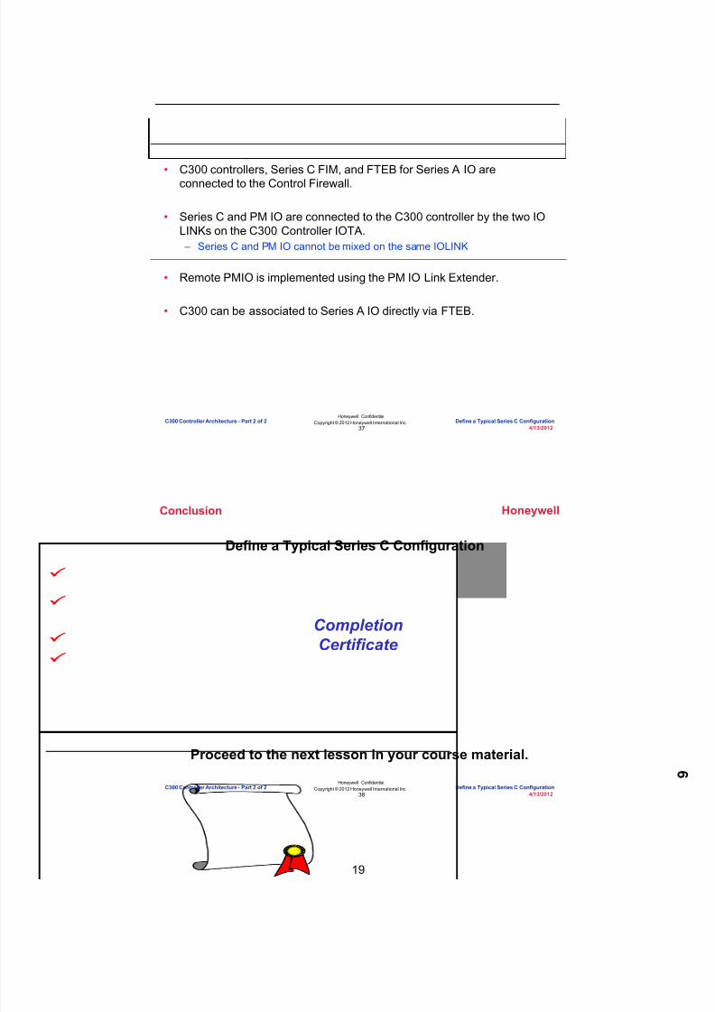
8/9/2019 Student Course Book- Automation
http://slidepdf.com/reader/full/student-course-book-automation 255/1165
19
Honeywell
Honeywell ConfidentialCopyright © 2012 Honeywell International Inc.
4/13/201237
Summary
• C300 controllers, Series C FIM, and FTEB for Series A IO areconnected to the Control Firewall.
• Series C and PM IO are connected to the C300 controller by the two IOLINKs on the C300 Controller IOTA. – Series C and PM IO cannot be mixed on the same IOLINK
• Remote PMIO is implemented using the PM IO Link Extender.
• C300 can be associated to Series A IO directly via FTEB.
C300 Controller Architecture - Part 2 of 2 Define a Typical Series C Configuration
Honeywell
Honeywell ConfidentialCopyright © 2012 Honeywell International Inc.
4/13/201238
Define a Typical Series C Configuration
CompletionCertificate
Proceed to the next lesson in your course material.
Conclusion
C300 Controller Architecture - Part 2 of 2 Define a Typical Series C Configuration

8/9/2019 Student Course Book- Automation
http://slidepdf.com/reader/full/student-course-book-automation 256/1165
Copyright © 201 2 Honeywell International Inc.
HPS Automation College written permission required to distributeHoneywell Confidential and Proprietary
This page was intentionally left blank.

8/9/2019 Student Course Book- Automation
http://slidepdf.com/reader/full/student-course-book-automation 257/1165
1
1
Honeywell ConfidentialCopyright © 2012 Honeywell International Inc.
4/13/2012
Describe Performance Calculations
Performance Calculations and Monitoring Describe Performance CalculationsPerformance Calculations and Monitoring Describe Performance Calculations
Honeywell
Honeywell ConfidentialCopyright © 2012 Honeywell International Inc.
4/13/20122
Overview
• Each controller can be configured and used differently – Ex: – Base execution period of the CEE – Number, type, execution period of CMs – Number, size of SCMs
• Controller configuration determines its: – Processor loading – Memory used
• Controller performance is expressed in units: – C200 & C200E:
• Processing Units (PU)• Memory Units (MU)
– C300 Execution Units (XU)• Control XU – same idea (and sometimes referred to) as PU• Communication XU (peer-to-peer, display communication)• IO XU – (IOLink – sometimes referred to as Link Units)• Memory Units (MU) (C200/C200E/C300)
Performance Calculations and Monitoring Describe Performance Calculations

8/9/2019 Student Course Book- Automation
http://slidepdf.com/reader/full/student-course-book-automation 258/1165
2
Honeywell
Honeywell ConfidentialCopyright © 2012 Honeywell International Inc.
4/13/20123
Processing Unit (PU)
• The measure of a controller’s capacity to execute control strategies – Quantifies the amount of processing time necessary to complete a logic
execution
• Items consuming PUs include: CMs, SCMs, Series A IOMs – Series C IOMs and PMIO do NOT consume PUs
• PU specifications are defined based on a typical Control module types – Example:
• A “typical” regulatory control (PID) CM consumes about 3 PUs• A Redundant C200’s capacity is 1600 PUs
– Approximately 530 Reg. Ctl CMs (executing once per second)
Performance Calculations and Monitoring Describe Performance Calculations
Honeywell
Honeywell ConfidentialCopyright © 2012 Honeywell International Inc.
4/13/20124
Execution Unit (XU)
• Because a single Processing Unit specification is not possible for aC300 controller: – The concept of an Execution Unit (XU) is introduced to model how a C300
controller’s processing power is spent.
• Execution Unit (XU) is specific to the C300 controller and is requiredbecause the C300 controller performs multiple functions such as: – Control – CPU time used to execute control strategies (similar to PUs of a
C200). – IO – CPU time used to support and communicate with IO on the two IO Links
and with ControlNet-resident Series A IO which is connected via FTEBmodules.
– Communication – CPU time used for communicating with peer nodes (e.g.C300s, C200s, ACEs, FIM4s, etc.) and displays.
• Execution Unit (XU) is a measure of C300 processing capability persecond: – 1 XU of a C300 is logically equal to 1 PU of a C200/ACE.
Performance Calculations and Monitoring Describe Performance Calculations

8/9/2019 Student Course Book- Automation
http://slidepdf.com/reader/full/student-course-book-automation 259/1165
3
Honeywell
Honeywell ConfidentialCopyright © 2012 Honeywell International Inc.
4/13/20125
C300 Communication XU
• Execution Units (XU) required to support the specified communicationsare calculated automatically from the following inputs: – Number of Peer Connections (node type is not critical) – nodes considered
as peers include C300, C200/C200E, ACE, FIM4 – Number of Console Stations associated with Experion Server/cluster – Number of Parameters per second for display throughput – Number of Messages per second
• Number of Messages/second is calculated from the number ofExchange blocks, Push block stores, and SCM block stores that initiateand respond to requests.
Performance Calculations and Monitoring Describe Performance Calculations
Honeywell
Honeywell ConfidentialCopyright © 2012 Honeywell International Inc.
4/13/20126
C200 & C200E Resource Usage
• ‘Base’ represents “Overhead” processing done by the controller • ‘Free’ is the recommended unused CPU capability
– 40% for 50ms C200/E, 60% for 5ms C200 (N/A for C200E)
• “Spend” the CPU resources available in each C200 / C200E – Depending on requirements
Free
Control
Base
PUsFor user
100
0
C200
4000 MU
C200E
16000 MU
PU Capacities:50ms non-redundant – 3600 PUs50ms redundant – 1600 PUs5ms non-redundant – 2400 PUs
C200 Only
Performance Calculations and Monitoring Describe Performance Calculations

8/9/2019 Student Course Book- Automation
http://slidepdf.com/reader/full/student-course-book-automation 260/1165
4
Honeywell
Honeywell ConfidentialCopyright © 2012 Honeywell International Inc.
4/13/20127
C300 Resource Usage
Free
Comm
Control
IO
Base
5500XUsFor user
100
0
• XU indicates the processingpower of the C300 – Control (Control XU) – IO (IO XU) – Communication (Comm XU)
• Decide how to “Spend” theCPU and memory resourcesavailable in each C300Controller – Depending on requirements
16000 MU
Performance Calculations and Monitoring Describe Performance Calculations
Honeywell
Honeywell ConfidentialCopyright © 2012 Honeywell International Inc.
4/13/20128
PU and MU Table for C200/C200E
Typical Module Types Processing ResourceConsumption (per module) MemoryResourceUsage
50/5 ms CEENon-Red
(PU/ModuleExecution)
50ms CEENon-Red
(PU/ModuleExecution)
50/5 ms CEENon-Red(MU/Mod)
Typical IO Module (Average consumptionof available IOMs)
0.3 0.19 0.6
Analog Data Acquisition Module 2.9 3.8 7.4
Small Analog Data Acquisition Module 0.47 0.43 1.0
Regulatory Control Module 2.8 2.8 3.9
Auxiliary Function Module 4.2 5.1 13.1
Digital Data Acquisition Module 1.2 1.2 3.1
Device Control Module 1.3 1.3 3.1
Logic Control Module 1.0 1.0 3.5
SCM 2.0 3.0 28.9
Small Digital Data Acquisition Module 0.22 0.14 0.6
Performance Calculations and Monitoring Describe Performance Calculations
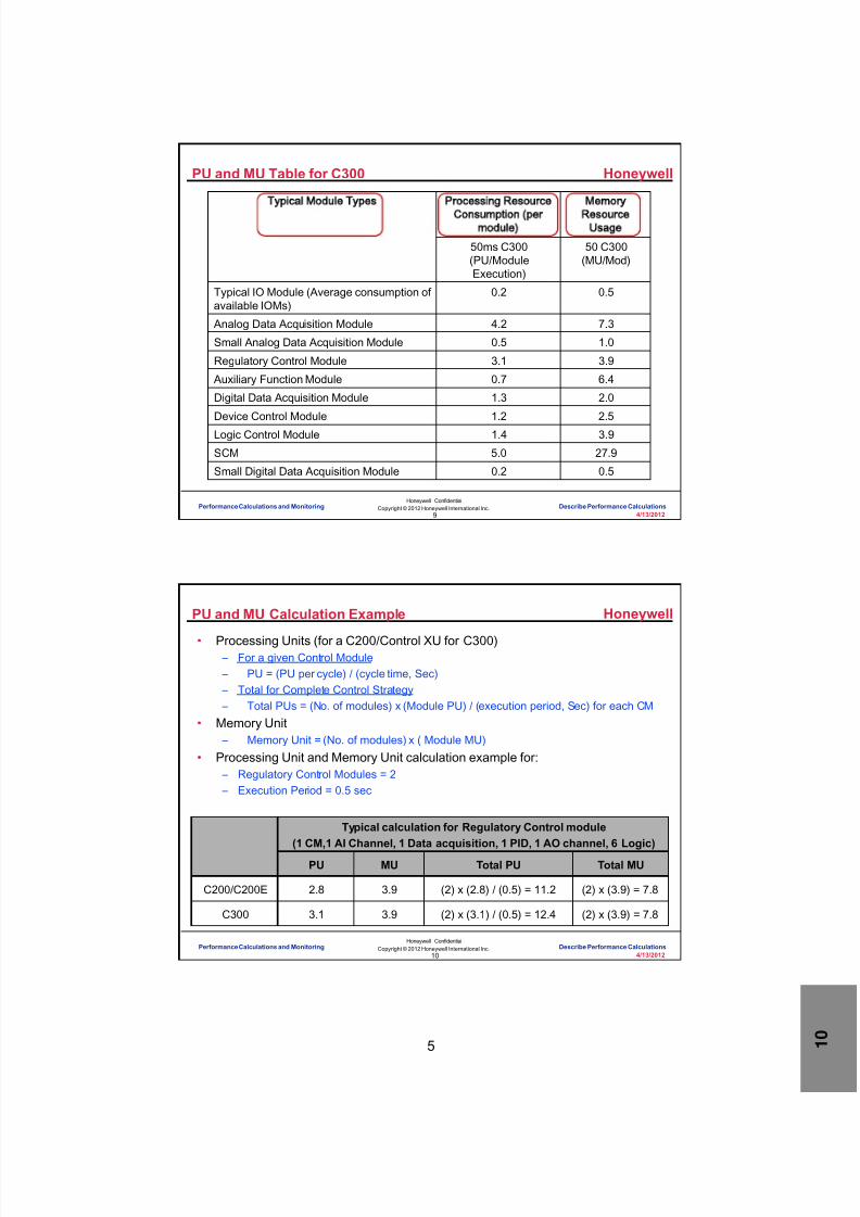
8/9/2019 Student Course Book- Automation
http://slidepdf.com/reader/full/student-course-book-automation 261/1165
5
Honeywell
Honeywell ConfidentialCopyright © 2012 Honeywell International Inc.
4/13/20129
PU and MU Table for C300
Typical Module Types Processing ResourceConsumption (per
module)
MemoryResource
Usage
50ms C300(PU/ModuleExecution)
50 C300(MU/Mod)
Typical IO Module (Average consumption ofavailable IOMs)
0.2 0.5
Analog Data Acquisition Module 4.2 7.3
Small Analog Data Acquisition Module 0.5 1.0
Regulatory Control Module 3.1 3.9
Auxiliary Function Module 0.7 6.4
Digital Data Acquisition Module 1.3 2.0
Device Control Module 1.2 2.5
Logic Control Module 1.4 3.9
SCM 5.0 27.9
Small Digital Data Acquisition Module 0.2 0.5
Performance Calculations and Monitoring Describe Performance Calculations
Honeywell
Honeywell ConfidentialCopyright © 2012 Honeywell International Inc.
4/13/201210
PU and MU Calculation Example
• Processing Units (for a C200/Control XU for C300) – For a given Control Module – PU = (PU per cycle) / (cycle time, Sec) – Total for Complete Control Strategy – Total PUs = (No. of modules) x (Module PU) / (execution period, Sec) for each CM
• Memory Unit – Memory Unit = (No. of modules) x ( Module MU)
• Processing Unit and Memory Unit calculation example for: – Regulatory Control Modules = 2 – Execution Period = 0.5 sec
Typical calculation for Regulatory Control module(1 CM,1 AI Channel, 1 Data acquisition, 1 PID, 1 AO channel, 6 Logic)
PU MU Total PU Total MU
C200/C200E 2.8 3.9 (2) x (2.8) / (0.5) = 11.2 (2) x (3.9) = 7.8
C300 3.1 3.9 (2) x (3.1) / (0.5) = 12.4 (2) x (3.9) = 7.8
Performance Calculations and Monitoring Describe Performance Calculations

8/9/2019 Student Course Book- Automation
http://slidepdf.com/reader/full/student-course-book-automation 262/1165
6
Honeywell
Honeywell ConfidentialCopyright © 2012 Honeywell International Inc.
4/13/201211
Correlation of PU/XU and % CPU loading
• The following table shows an estimate of the number of PUs / XUs that will
cause 1% CPU loading
• Note: All the values listed are approximate
• Example: For a C300, control strategy using 2000 PU will amount to a % CPU
usage of 22.22% – Calculated by formula 2000 PU /90 = 22..22%, seen at CPUCYCLEAVG[40] – Free CPU would be approximately 77% (100% – 22.22%), seen at CPUFREEAVG
Correlation Table for 1% CPU loading
Controller Number of PUs/XUs(~)
C200 (Non-Redundant) 50-60
C200 (Redundant) 20-30
C300 80-90
Performance Calculations and Monitoring Describe Performance Calculations
Honeywell
Honeywell ConfidentialCopyright © 2012 Honeywell International Inc.
4/13/201212
Monitor CPU % Loading
• XU of C300 and PU of C200/C200E/C300 are not shown directly – Inferred in terms of CPU Usage and CPU Free
• Recommended CPU free: C300: 20%, C200: 50ms: 40%, 5ms: 60%) – Displayed on faceplate of C200/C200E/C300 controller within Station – Within Control Builder for C300, this same information is on the statistics tab
of the controller template• For a C200/C200E this information is available on the statistics tab of
the CEE template
• Minimum CPU Free (%) – Indicates ‘minimum’ value recorded, since the controller power up or a last
statistics reset
Performance Calculations and Monitoring Describe Performance Calculations

8/9/2019 Student Course Book- Automation
http://slidepdf.com/reader/full/student-course-book-automation 263/1165
7
Honeywell
Honeywell ConfidentialCopyright © 2012 Honeywell International Inc.
4/13/201213
C300 CPU Free Alarms
• If the average free CPU available is lower than the limits (below), thenthe following alarms are initiated
• CPU Free Low – Threshold defaults to 20% and is user configurable
• On the C300 properties – Main tab – An alarm is generated when CPU Free is less than the threshold
• Displayed on the System Alarm Summary• Priority - LOW
• CPU Free Low Low – Threshold is fixed at 10% and is not user configurable – An alarm is generated when CPU Free is less than 10%
• Displayed on the System Alarm Summary
• Priority – HIGH
Performance Calculations and Monitoring Describe Performance Calculations
Honeywell
Honeywell ConfidentialCopyright © 2012 Honeywell International Inc.
4/13/201214
Execution Cycles (Phases)
• Execution period and phase = execution cycle
• Example: – A CM with a one second execution period (1000 ms) and a phase of
0 would execute at phase 0 and again at phase 20
8
PHASE (cycle)7654321
0
0109
03938371211
50 100 5004504003503002502001502000
1850600550
19001950
TIME (ms)
CEECM
This CEE base execution
period has 40 timing cycles(phases) of 50 ms each
Performance Calculations and Monitoring Describe Performance Calculations

8/9/2019 Student Course Book- Automation
http://slidepdf.com/reader/full/student-course-book-automation 264/1165
8
Honeywell
Honeywell ConfidentialCopyright © 2012 Honeywell International Inc.
4/13/201215
CPU Loading Tab – Cycle Loading Table
• The CPU Loading tab is one of two tabs containing CPU statistics usedfor maintenance and performance monitoring of the CEE
• View the average CPU (CPUCYCLEAVG) and maximum CPU(CPUCYCLEMAX) usage for a given control cycle (0 -39) – “Cycle 40” is the overall average (or max)
• Data shown is since last power up (or manual statistics reset)
Average percentage ofCentral Processing Unit
(CPU) processingpower used per cycle
Shows the historicalmaximum of Central
Processor Unit (CPU)processing power used
per cycle
Data is shown onlywhen accessed fromthe monitoring tab
Performance Calculations and Monitoring Describe Performance Calculations
Honeywell
Honeywell ConfidentialCopyright © 2012 Honeywell International Inc.
4/13/201216
CPU Loading Tab Parameters
Parameter Description Recommended
CPUCYCLEAVG[40] Average CPU used across all 40 CEEexecution cycles
<60%
CPUCYCLEAVG[0..39]
Average CPU used for individual cyclesUnits are percent of 50 ms cycle. Indexcorresponds to the cycle (phase)number.
<60%
CPUCYCLEMAX[40]Maximum of CPU used for all 40 CEEexecution cycles <85%
CPUCYCLEMAX[0..39]
Historical maximum of the CPU used byeach execution cycle. Units are percentof 50 ms cycle. Index corresponds to thecycle (phase) number.
<85%
• Recommendations for C200s and C300s with 50 ms execution period
• For C200 5ms, CPU Cycle average values should be less than 40%• For C300 20ms, CPU Cycle average values should be less than 50%• More details: Experion PKS Control Builder Components Theory manual
Performance Calculations and Monitoring Describe Performance Calculations

8/9/2019 Student Course Book- Automation
http://slidepdf.com/reader/full/student-course-book-automation 265/1165
9
Honeywell
Honeywell ConfidentialCopyright © 2012 Honeywell International Inc.
4/13/201217
CPU Overrun
• An overrun occurs when any container blocks assigned to a cycle fail toexecute within the cycle – Indicates the CPU is scheduled to perform more tasks than can be
completed within a base cycle
• Overruns are diagnostic events reported by the CEE as ‘CPU cycleoverruns‘
• Getting an overrun occasionally (may not be bad) – Ex: an overrun occurred when downloading a large number of CMs
• Getting overruns periodically (this is bad) – The CPU is routinely deferring execution 1 (or more) CMs to the next cycle – Needs to be fixed
• Note the cycle numbers• Load balance• Possibly remove control
strategies (CMs, SCMs, etc.)from the CEE
Data is shown onlywhen accessed fromthe monitoring tab
Performance Calculations and Monitoring Describe Performance Calculations
Honeywell
Honeywell ConfidentialCopyright © 2012 Honeywell International Inc.
4/13/201218
Cycle Overrun Alarm Conditions
If Controller is . . . CEE reports alarm if . . . CEE clears alarm if . . .
CPM (50 msBASEPERIOD)
Two consecutive intervals of2000 milliseconds have atleast one cycle overrun.
Four consecutiveintervals of 2000milliseconds have nocycle overruns.
ACE (500 msBASEPERIOD)
Two consecutive intervals of20 seconds have at least
one cycle overrun.
Four consecutiveintervals of 20 seconds
have no cycle overruns.
• The conditions for reporting and clearing overrun alarms aresummarized below.
• A CEE configuration that causes regular overruns should be changed byreducing the total load or rebalancing the load across timing cycles.
Performance Calculations and Monitoring Describe Performance Calculations

8/9/2019 Student Course Book- Automation
http://slidepdf.com/reader/full/student-course-book-automation 266/1165
10
Honeywell
Honeywell ConfidentialCopyright © 2012 Honeywell International Inc.
4/13/201219
Load Balancing
• Procedure by which overruns are eliminated or minimized byautomatically assigning scheduling parameters to container blocks.
• Scheduling parameters – Period - The amount of time between two consecutive executions of a CM or
SCM block – Phase - Determines the set of cycles in which a container block executes – Execution Order - The time sequence in which container blocks execute
Performance Calculations and Monitoring Describe Performance Calculations
Honeywell
Honeywell ConfidentialCopyright © 2012 Honeywell International Inc.
4/13/201220
Memory Units
• Memory Unit (MU) – The units used to define the amount of memory used by control strategies
(CMs, SCMs, etc.)
• The Memory tab indicates – Total user memory – Currently used memory – Currently Free memory
Currently Used Memory
Total User Memory Units in Kb
Currently Free Memory
C200
C200E,C300
Data is shown onlywhen accessed fromthe Monitoring tab.
Performance Calculations and Monitoring Describe Performance Calculations
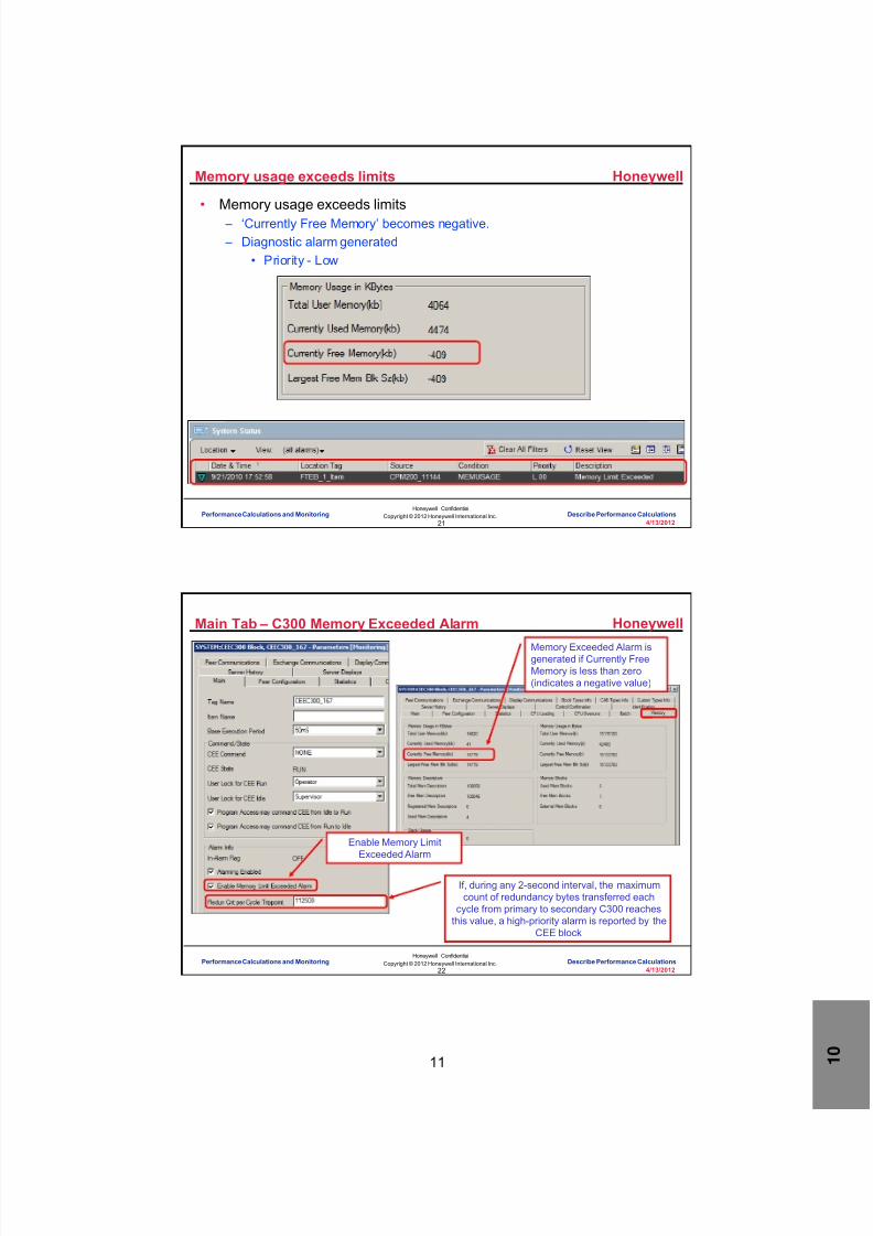
8/9/2019 Student Course Book- Automation
http://slidepdf.com/reader/full/student-course-book-automation 267/1165
11
Honeywell
Honeywell ConfidentialCopyright © 2012 Honeywell International Inc.
4/13/201221
Memory usage exceeds limits
• Memory usage exceeds limits – ‘Currently Free Memory’ becomes negative. – Diagnostic alarm generated
• Priority - Low
Performance Calculations and Monitoring Describe Performance Calculations
Honeywell
Honeywell ConfidentialCopyright © 2012 Honeywell International Inc.
4/13/201222
Main Tab – C300 Memory Exceeded Alarm
Enable Memory LimitExceeded Alarm
Memory Exceeded Alarm isgenerated if Currently FreeMemory is less than zero(indicates a negative value)
If, during any 2-second interval, the maximumcount of redundancy bytes transferred each
cycle from primary to secondary C300 reachesthis value, a high-priority alarm is reported by the
CEE block
Performance Calculations and Monitoring Describe Performance Calculations

8/9/2019 Student Course Book- Automation
http://slidepdf.com/reader/full/student-course-book-automation 268/1165
12
Honeywell
Honeywell ConfidentialCopyright © 2012 Honeywell International Inc.
4/13/201223
EXECTIMER
• Execution Timer Block (EXECTIMER) – Used to measure execution timing of Control Modules, SCMs, RCMs, UCMs – Used to measure the timing of individual basic blocks or groups of basic
blocks within Control module – Used to measure the execution time for Control Strategy to be reused
• Supported controllers – C200E, C300, ACE, with their simulation environments and C300 20 ms
Performance Calculations and Monitoring Describe Performance Calculations
Honeywell
Honeywell ConfidentialCopyright © 2012 Honeywell International Inc.
4/13/201224
EXECTIMER – Configuration and Limitations
• EXECTIMER is used by creating twoinstances – One instance marks beginning of
time interval – Other instance marks the end of a
time interval
• Connect the output parameter ofbeginning EXECTIMER to inputparameter of end EXECTIMER
• Limitations: EXECTIMER cannot beused for any of the followingpurposes – Measuring timing effects between
Different execution Environments – Measuring timing effects between
Execution Environment and IO – Measuring timing effects between
Execution Environment and OPCgateway or OPC server
Performance Calculations and Monitoring Describe Performance Calculations

8/9/2019 Student Course Book- Automation
http://slidepdf.com/reader/full/student-course-book-automation 269/1165

8/9/2019 Student Course Book- Automation
http://slidepdf.com/reader/full/student-course-book-automation 270/1165
Copyright © 201 2 Honeywell International Inc.
HPS Automation College written permission required to distributeHoneywell Confidential and Proprietary
This page was intentionally left blank.

8/9/2019 Student Course Book- Automation
http://slidepdf.com/reader/full/student-course-book-automation 271/1165
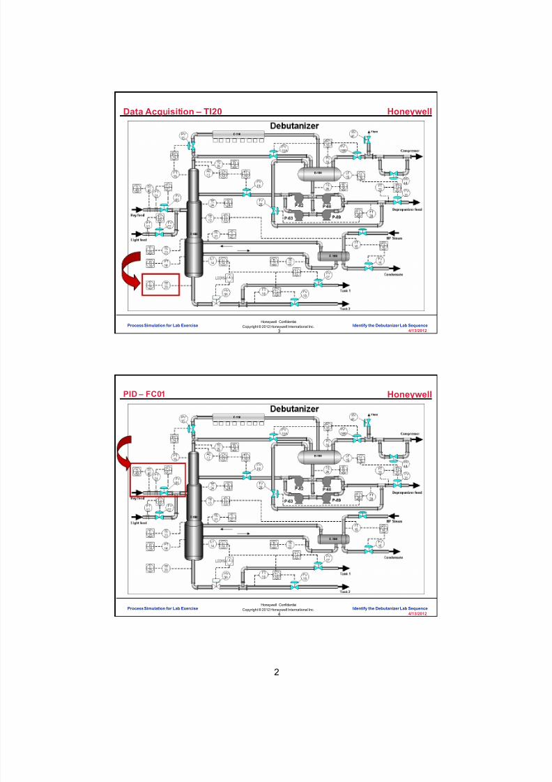
8/9/2019 Student Course Book- Automation
http://slidepdf.com/reader/full/student-course-book-automation 272/1165
2
Honeywell
Honeywell ConfidentialCopyright © 2012 Honeywell International Inc.
4/13/20123
Data Acquisition – TI20
Process Simulation for Lab Exercise Identify the Debutanizer Lab Sequence
Honeywell
Honeywell ConfidentialCopyright © 2012 Honeywell International Inc.
4/13/20124
PID – FC01
Process Simulation for Lab Exercise Identify the Debutanizer Lab Sequence

8/9/2019 Student Course Book- Automation
http://slidepdf.com/reader/full/student-course-book-automation 273/1165
3
Honeywell
Honeywell ConfidentialCopyright © 2012 Honeywell International Inc.
4/13/20125
PID Split Range Outputs – PC16
Process Simulation for Lab Exercise Identify the Debutanizer Lab Sequence
Honeywell
Honeywell ConfidentialCopyright © 2012 Honeywell International Inc.
4/13/20126
Cascade PID – LC14 and FC17
Process Simulation for Lab Exercise Identify the Debutanizer Lab Sequence

8/9/2019 Student Course Book- Automation
http://slidepdf.com/reader/full/student-course-book-automation 274/1165
4
Honeywell
Honeywell ConfidentialCopyright © 2012 Honeywell International Inc.
4/13/20127
Cascade PID with 2 Secondaries LC 14 , FC17 and FC18
Process Simulation for Lab Exercise Identify the Debutanizer Lab Sequence
Honeywell
Honeywell ConfidentialCopyright © 2012 Honeywell International Inc.
4/13/20128
Device Control - Pumps
Process Simulation for Lab Exercise Identify the Debutanizer Lab Sequence
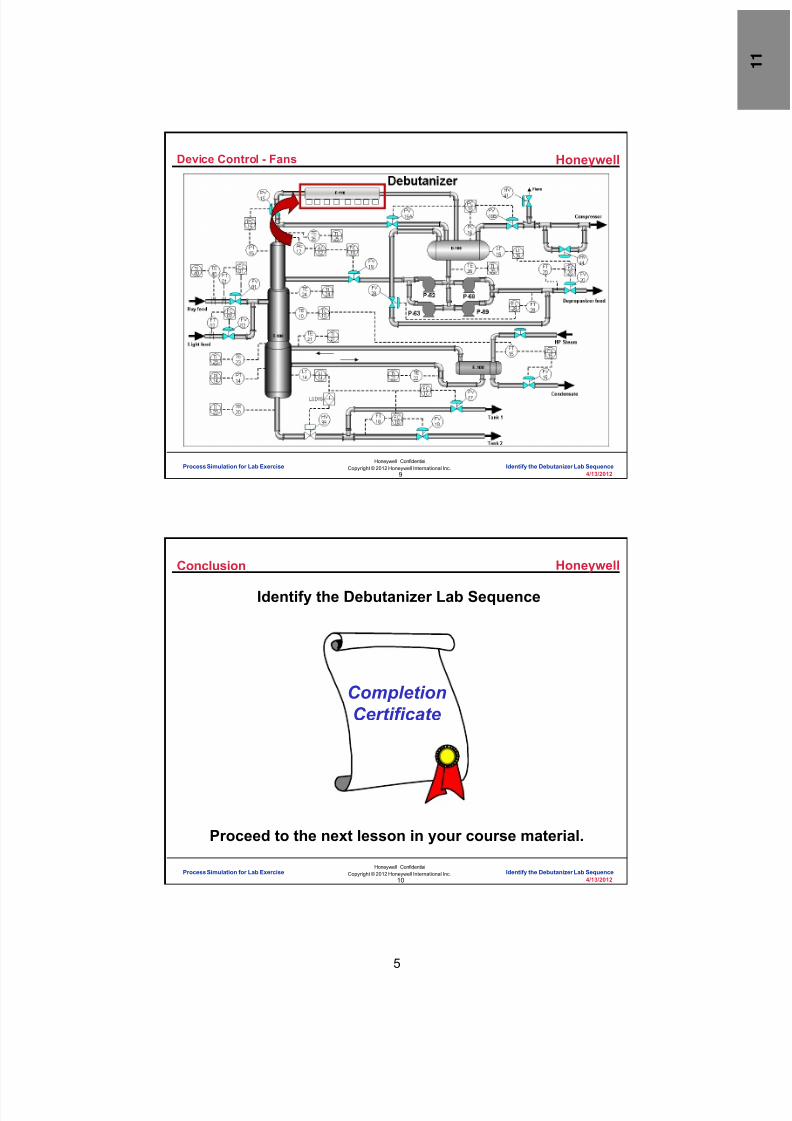
8/9/2019 Student Course Book- Automation
http://slidepdf.com/reader/full/student-course-book-automation 275/1165
5
Honeywell
Honeywell ConfidentialCopyright © 2012 Honeywell International Inc.
4/13/20129
Device Control - Fans
Process Simulation for Lab Exercise Identify the Debutanizer Lab Sequence
Honeywell
Honeywell ConfidentialCopyright © 2012 Honeywell International Inc.
4/13/201210
Conclusion
Identify the Debutanizer Lab Sequence
CompletionCertificate
Proceed to the next lesson in your course material.
Process Simulation for Lab Exercise Identify the Debutanizer Lab Sequence

8/9/2019 Student Course Book- Automation
http://slidepdf.com/reader/full/student-course-book-automation 276/1165
Copyright © 201 2 Honeywell International Inc.
HPS Automation College written permission required to distributeHoneywell Confidential and Proprietary
This page was intentionally left blank.

8/9/2019 Student Course Book- Automation
http://slidepdf.com/reader/full/student-course-book-automation 277/1165
1
1
Honeywell ConfidentialCopyright © 2012 Honeywell International Inc.
4/13/2012
Describe the EXCEL Simulation Used forLabs
EXCEL Simulation Describe the EXCEL Simulation Used for LabsEXCEL Simulation Describe the EXCEL Simulation Used for Labs
Honeywell
Honeywell ConfidentialCopyright © 2012 Honeywell International Inc.
4/13/20122
Introduction
• In this lesson, you will learn howthe Excel Data Exchange program,a licensed Honeywell option, workswith the Excel simulationspreadsheet and process simulatorused in this course.
• At the conclusion of this lesson,you will be able to:
– Identify the two function blockparameters available only in thesimulated control execution (SCE)environment
– Identify the three simulation modesavailable in the SCE environment
– Explain the purpose of closing andreopening the spreadsheet afterconfiguring and loading new tagsto the system
EXCEL Simulation Describe the EXCEL Simulation Used for Labs
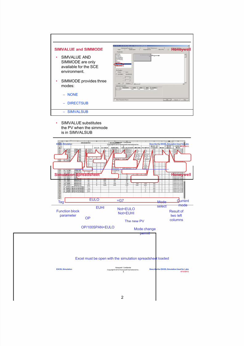
8/9/2019 Student Course Book- Automation
http://slidepdf.com/reader/full/student-course-book-automation 278/1165
2
Honeywell
Honeywell ConfidentialCopyright © 2012 Honeywell International Inc.
4/13/20123
SIMVALUE and SIMMODE
• SIMVALUE ANDSIMMODE are onlyavailable for the SCEenvironment.
• SIMMODE provides threemodes:
– NONE
– DIRECTSUB
– SIMVALSUB
• SIMVALUE substitutesthe PV when the simmodeis in SIMVALSUB
EXCEL Simulation Describe the EXCEL Simulation Used for Labs
Honeywell
Honeywell ConfidentialCopyright © 2012 Honeywell International Inc.
4/13/20124
Simulation Spreadsheet
OP
OP/100SPAN+EULO Mode changepermit
Modeselect
Result of two left
columns
Currentmode
Not<EULONot>EUHI
EUHIFunction block
parameter
TagEULO
The new PV
=G7
Excel must be open with the simulation spreadsheet loaded
EXCEL Simulation Describe the EXCEL Simulation Used for Labs

8/9/2019 Student Course Book- Automation
http://slidepdf.com/reader/full/student-course-book-automation 279/1165
3
Honeywell
Honeywell ConfidentialCopyright © 2012 Honeywell International Inc.
4/13/20125
Simulation Spreadsheet
• Some of these tags will be built as a part of the lab and some imported.• There are tags configured in the spreadsheet which do not exist in the
Experion server at the start of the class.
EXCEL Simulation Describe the EXCEL Simulation Used for Labs
Honeywell
Honeywell ConfidentialCopyright © 2012 Honeywell International Inc.
4/13/20126
Enabling Excel Simulation
• To make Excel Spreadsheet Write enabled , uncheck “Disable WritesVia the Network API” option
EXCEL Simulation Describe the EXCEL Simulation Used for Labs

8/9/2019 Student Course Book- Automation
http://slidepdf.com/reader/full/student-course-book-automation 280/1165
4
Honeywell
Honeywell ConfidentialCopyright © 2012 Honeywell International Inc.
4/13/20127
Conclusion
Describe the Excel Simulation Used for Labs
CompletionCertificate
Proceed to the next lesson in your course material.
EXCEL Simulation Describe the EXCEL Simulation Used for Labs
Honeywell
Honeywell ConfidentialCopyright © 2012 Honeywell International Inc.
4/13/20128
This page intentionally left blank
EXCEL Simulation Describe the EXCEL Simulation Used for Labs
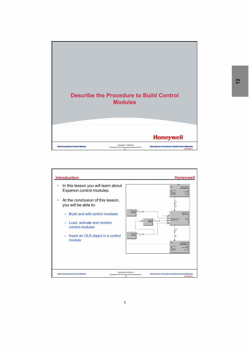
8/9/2019 Student Course Book- Automation
http://slidepdf.com/reader/full/student-course-book-automation 281/1165
1
1
Honeywell ConfidentialCopyright © 2012 Honeywell International Inc.
4/13/2012
Describe the Procedure to Build ControlModules
Data Acquisition Control Module Describe the Procedure to Build Control ModulesData Acquisition Control Module Describe the Procedure to Build Control Modules
Honeywell
Honeywell ConfidentialCopyright © 2012 Honeywell International Inc.
4/13/20122
Introduction
• In this lesson you will learn aboutExperion control modules.
• At the conclusion of this lesson,you will be able to:
– Build and edit control modules
– Load, activate and monitor control modules
– Insert an OLE object in a controlmodule
Data Acquisition Control Module Describe the Procedure to Build Control Modules

8/9/2019 Student Course Book- Automation
http://slidepdf.com/reader/full/student-course-book-automation 282/1165
2
Honeywell
Honeywell ConfidentialCopyright © 2012 Honeywell International Inc.
4/13/20123
Topics
• Building and Editing Control Modules
• Loading, Activating and Monitoring Control Modules
• Inserting an OLE Object in a Control Module
Data Acquisition Control Module Describe the Procedure to Build Control Modules
Honeywell
Honeywell ConfidentialCopyright © 2012 Honeywell International Inc.
4/13/20124
Methods to Add a New Control Module (CM)
• Three methods to add a CM: – From the Library:
• Drag and drop onto a CEE• Drag and drop onto a blank area
– From the Menu:• File>New>Control Module
123
Data Acquisition Control Module Describe the Procedure to Build Control Modules

8/9/2019 Student Course Book- Automation
http://slidepdf.com/reader/full/student-course-book-automation 283/1165
3
Honeywell
Honeywell ConfidentialCopyright © 2012 Honeywell International Inc.
4/13/20125
Different Actions Based on Method Used
Method Used Name NewDialog?
Put inUnassigned?
Drop on CEE Yes No
Drop to Blank Yes Yes
Menu No Yes
Depending on the methodused to add the CM, your
CM may be automaticallyassigned to your CEE, or itmay be put in Unassigned.
Depending on the methodused to add the CM, youmay or may not be presentedwith this dialog box.
Data Acquisition Control Module Describe the Procedure to Build Control Modules
Honeywell
Honeywell ConfidentialCopyright © 2012 Honeywell International Inc.
4/13/20126
Assigning Control Modules to a CEE
2
3
1a
1b
Required if the “menu” methodwas used, or if the IOM wasdropped onto a blank area.
Assignedto CEE
Data Acquisition Control Module Describe the Procedure to Build Control Modules

8/9/2019 Student Course Book- Automation
http://slidepdf.com/reader/full/student-course-book-automation 284/1165
4
Honeywell
Honeywell ConfidentialCopyright © 2012 Honeywell International Inc.
4/13/20127
Opening Chart View to Configure a Control Module
Double lick
When the “File Method” isused to add a new ControlModule, the Chart Viewwindow is automaticallyopened.
Data Acquisition Control Module Describe the Procedure to Build Control Modules
Honeywell
Honeywell ConfidentialCopyright © 2012 Honeywell International Inc.
4/13/20128
Add Function Blocks
• Add Function Blocks from the library to the CM• Add them in the order in which they should execute
– Ex: AI, DACA, PIDA, AO
TIP:After adding function blocks,save your CM. This allowsthe point picker to displaythe new function blocks.
1
2
3
4
Series A
Series C
Data Acquisition Control Module Describe the Procedure to Build Control Modules
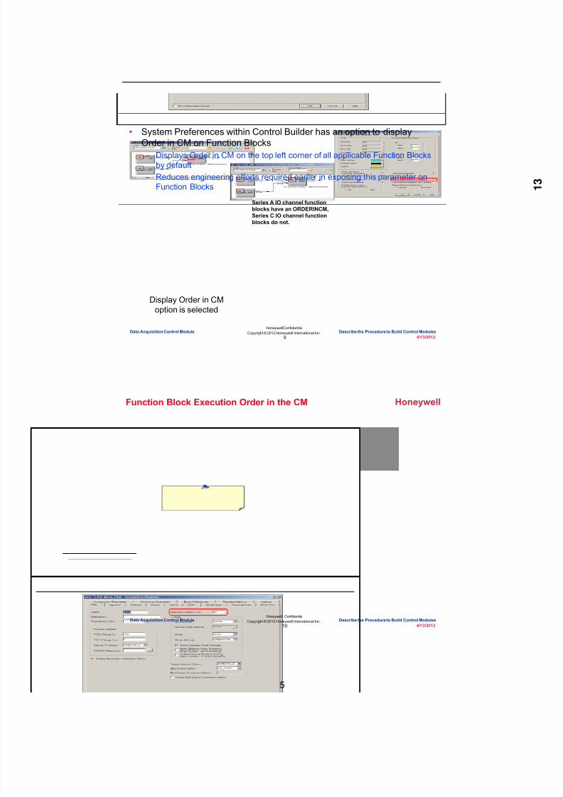
8/9/2019 Student Course Book- Automation
http://slidepdf.com/reader/full/student-course-book-automation 285/1165
5
Honeywell
Honeywell ConfidentialCopyright © 2012 Honeywell International Inc.
4/13/20129
Provide Automatic ORDERINCM
• System Preferences within Control Builder has an option to displayOrder in CM on Function Blocks – Displays Order in CM on the top left corner of all applicable Function Blocks
by default – Reduces engineering efforts required earlier in exposing this parameter on
Function Blocks
Display Order in CMoption is selected
Series A IO channel functionblocks have an ORDERINCM,Series C IO channel functionblocks do not.
Data Acquisition Control Module Describe the Procedure to Build Control Modules
Honeywell
Honeywell ConfidentialCopyright © 2012 Honeywell International Inc.
4/13/201210
Function Block Execution Order in the CM
Data Acquisition Control Module Describe the Procedure to Build Control Modules

8/9/2019 Student Course Book- Automation
http://slidepdf.com/reader/full/student-course-book-automation 286/1165
6
Honeywell
Honeywell ConfidentialCopyright © 2012 Honeywell International Inc.
4/13/201211
Adding IO Channel Function Blocks to the Control Module
• A IO channel can be added to the CM by either dragging it from an IOMin the Project tab, or by dragging it from the Library – When added from an IOM in Project, the channel is automatically assigned
to a specific channel on a specific IOM
Drag andDrop
Drag andDrop
Only availablefor SeriesCchannels
This method is availablefor all channel types.The channel must bemanually assignedlater.
Data Acquisition Control Module Describe the Procedure to Build Control Modules
Honeywell
Honeywell ConfidentialCopyright © 2012 Honeywell International Inc.
4/13/201212
Manually Assigning a SeriesC Channel
X
Data Acquisition Control Module Describe the Procedure to Build Control Modules

8/9/2019 Student Course Book- Automation
http://slidepdf.com/reader/full/student-course-book-automation 287/1165
7
Honeywell
Honeywell ConfidentialCopyright © 2012 Honeywell International Inc.
4/13/201213
Adding and Manually Assigning a Series A Channel
Drag &Drop
DoubleClick
Data Acquisition Control Module Describe the Procedure to Build Control Modules
Honeywell
Honeywell ConfidentialCopyright © 2012 Honeywell International Inc.
4/13/201214
Configure the CM and Each Function Block
• Double click on a blank space to configure the properties of the CM• Double click on each function block to configure its properties• The properties of the CM will be covered in coming slides
Data Acquisition Control Module Describe the Procedure to Build Control Modules
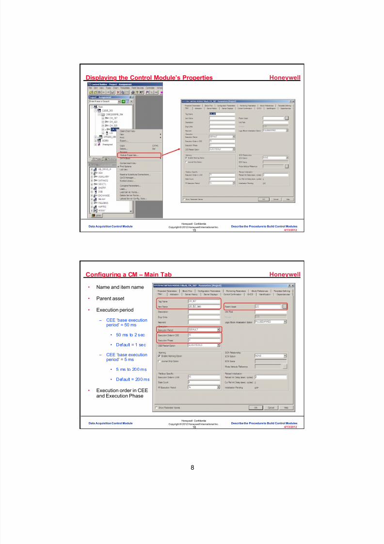
8/9/2019 Student Course Book- Automation
http://slidepdf.com/reader/full/student-course-book-automation 288/1165
8
Honeywell
Honeywell ConfidentialCopyright © 2012 Honeywell International Inc.
4/13/201215
Displaying the Control Module’s Properties
Data Acquisition Control Module Describe the Procedure to Build Control Modules
Honeywell
Honeywell ConfidentialCopyright © 2012 Honeywell International Inc.
4/13/201216
Configuring a CM – Main Tab
• Name and item name
• Parent asset
• Execution period
– CEE ‘base executionperiod’ = 50 ms
• 50 ms to 2 sec
• Default = 1 sec
– CEE ‘base executionperiod’ = 5 ms
• 5 ms to 200 ms
• Default = 200 ms
• Execution order in CEEand Execution Phase
Data Acquisition Control Module Describe the Procedure to Build Control Modules

8/9/2019 Student Course Book- Automation
http://slidepdf.com/reader/full/student-course-book-automation 289/1165
9
Honeywell
Honeywell ConfidentialCopyright © 2012 Honeywell International Inc.
4/13/201217
Configuring a CM – Execution Cycle
8
PHASE7654321
0
0109
03938371211
50100 500
450400
350300
250200
1502000
1850600
5501900
1950
TIME (ms)
• Execution period and phase = execution cycle
• Examples:
– A CM with a one second execution period (1000 ms) and a phase of0 would execute at phase 0 and again at phase 20
– A CM with an execution period of 200 milliseconds and a phase of 1will execute in cycles 1, 5, 9, ... 37
This CEE base executionperiod has 40 timing phases
(cycles) of 50 ms each
Data Acquisition Control Module Describe the Procedure to Build Control Modules
Honeywell
Honeywell ConfidentialCopyright © 2012 Honeywell International Inc.
4/13/201218
CPU Loading
CEEdetail
display
Data Acquisition Control Module Describe the Procedure to Build Control Modules

8/9/2019 Student Course Book- Automation
http://slidepdf.com/reader/full/student-course-book-automation 290/1165
10
Honeywell
Honeywell ConfidentialCopyright © 2012 Honeywell International Inc.
4/13/201219
Together, the CM execution period and phase define the:
Correct - Click anywhere tocontinueIncorrect - Click anywhere to
continue
You answered this correctly!
Your answer:
The correct answer is:
You did not answer this questioncompletelyYou must answer the question
before continuing
Submit Clear
Question 1 : CM Period and Phase
A) Execution cycle
B) Execution phase hour
C) Execution phase minute
D) Execution order
Data Acquisition Control Module Describe the Procedure to Build Control Modules
Honeywell
Honeywell ConfidentialCopyright © 2012 Honeywell International Inc.
4/13/201220
Reload Initialization
• Reload Initializationparameters on the CMprovide additionalcontrol over thebehavior of CMs
• In Execution Cycles• These parameters are
supported by – C300 – C200E – ACE
• Details on the nextslide
Data Acquisition Control Module Describe the Procedure to Build Control Modules

8/9/2019 Student Course Book- Automation
http://slidepdf.com/reader/full/student-course-book-automation 291/1165
11
Honeywell
Honeywell ConfidentialCopyright © 2012 Honeywell International Inc.
4/13/201221
Reload Initialization Parameters
• RELOADINIDLY – Initialization delay (integer value to define number of CM execution cycles) – When CM is reloaded, and the RELOADINIDLY is set to non-zero value
• CM parameters are not visible to local and peer pull clients• Local and Peer pull clients hold last fetched output until initialization
delay has expired – Default value is 2 execution cycles
• Depending on CM configuration, user can assign more than 2 executioncycles
• CURRELINIDLY – Indicates the count of execution cycles before initialization delay expires – When a CM is reloaded
• CURRELINIDLY is set to RELOADINIDLY – When a CM is activated
• CURRELINIDLY will begin countdown to zero – When CURRELINIDLY is zero
• Local and Peer pull clients can view parameters from the reloaded CM
Data Acquisition Control Module Describe the Procedure to Build Control Modules
Honeywell
Honeywell ConfidentialCopyright © 2012 Honeywell International Inc.
4/13/201222
Connecting Function Blocks with the Wiring Tool
Not yetconnected
Data Acquisition Control Module Describe the Procedure to Build Control Modules

8/9/2019 Student Course Book- Automation
http://slidepdf.com/reader/full/student-course-book-automation 292/1165
12
Honeywell
Honeywell ConfidentialCopyright © 2012 Honeywell International Inc.
4/13/201223
Example Analog CM – CM, Blocks, Par. Conn, XRef, etc.
Analog Loop CM
1
2
4
3
3
5
3
5
Data Acquisition Control Module Describe the Procedure to Build Control Modules
Honeywell
Honeywell ConfidentialCopyright © 2012 Honeywell International Inc.
4/13/201224
Example CM – Device Control
Device Control CM
Expanded toshow
functionblocks
Logic/interlocks
Inputs
Outputs
Data Acquisition Control Module Describe the Procedure to Build Control Modules

8/9/2019 Student Course Book- Automation
http://slidepdf.com/reader/full/student-course-book-automation 293/1165
13
Honeywell
Honeywell ConfidentialCopyright © 2012 Honeywell International Inc.
4/13/201225
Permissive/InterlocksDevice Control Detail Display
2-state
Data Acquisition Control Module Describe the Procedure to Build Control Modules
Honeywell
Honeywell ConfidentialCopyright © 2012 Honeywell International Inc.
4/13/201226
Question 2: Execution Order in a CM
No. "Execution Order in a CM" is the sequentialexecution order of function blocks in a CM.
Click anywhere to continue.
No. "Execution Order in a CM" is the sequentialexecution order of function blocks in a CM.
Click anywhere to continue.
Yes! "Execution Order in a CM" is the sequentialexecution order of function blocks in a CM.
Click anywhere to continue.
Correct - Click anywhere to continueIncorrect - Click anywhere to continueYou answered this correctly!
Your answer:The correct answer is:
You did not answer this question completelyYou must answer the question beforecontinuing
Submit Clear
No. "Execution Order in a CM" is the sequentialexecution order of function blocks in a CM.
Click anywhere to continue.
A) All function blocks with the sameexecution order in multiple CMsare executed in parallel
B) The execution cycle of the CMin the CEE
C) The execution phase of thefunction block in the CEE
D) The sequential execution orderof function blocks in a CM
Which of these is a definition of the Execution Order in a CM?
Data Acquisition Control Module Describe the Procedure to Build Control Modules

8/9/2019 Student Course Book- Automation
http://slidepdf.com/reader/full/student-course-book-automation 294/1165
14
Honeywell
Honeywell ConfidentialCopyright © 2012 Honeywell International Inc.
4/13/201227
Topics
• Building and Editing Control Modules
• Loading, Activating and Monitoring Control Modules
• Inserting an OLE Object in a Control Module
Data Acquisition Control Module Describe the Procedure to Build Control Modules
Honeywell
Honeywell ConfidentialCopyright © 2012 Honeywell International Inc.
4/13/201228
Initiating Load of CMs
1
3
2
Right-click
Data Acquisition Control Module Describe the Procedure to Build Control Modules

8/9/2019 Student Course Book- Automation
http://slidepdf.com/reader/full/student-course-book-automation 295/1165
15
Honeywell
Honeywell ConfidentialCopyright © 2012 Honeywell International Inc.
4/13/201229
Loading CMs – First Time
Check the appropriateboxes
Data Acquisition Control Module Describe the Procedure to Build Control Modules
Honeywell
Honeywell ConfidentialCopyright © 2012 Honeywell International Inc.
4/13/201230
Loading CMs Which Had Previously Been Downloaded
• If a CM had previously been downloaded, it must be inactivated prior tobeing re-loaded – Can be done manually from the Monitoring tab BEFORE the load is initiated – Can be done as part of the load process by selecting the checkbox
Before inactivating a CM,MAKE SURE:Operations personnel are awareProcess is in the proper state
Data Acquisition Control Module Describe the Procedure to Build Control Modules

8/9/2019 Student Course Book- Automation
http://slidepdf.com/reader/full/student-course-book-automation 296/1165
16
Honeywell
Honeywell ConfidentialCopyright © 2012 Honeywell International Inc.
4/13/201231
Activating/Inactivating CMs
Right-click
Data Acquisition Control Module Describe the Procedure to Build Control Modules
Honeywell
Honeywell ConfidentialCopyright © 2012 Honeywell International Inc.
4/13/201232
Monitoring CMs – Scale Factor
Monitoring/Chart Visualization
Scale FactorIcon
Data Acquisition Control Module Describe the Procedure to Build Control Modules

8/9/2019 Student Course Book- Automation
http://slidepdf.com/reader/full/student-course-book-automation 297/1165
17
Honeywell
Honeywell ConfidentialCopyright © 2012 Honeywell International Inc.
4/13/201233
Which of the following is not a way to load a control module?
Correct - Click anywhere tocontinue
Incorrect - Click anywhere tocontinueYou answered this correctly!
Your answer:The correct answer is: You did not answer this questioncompletely
You must answer the questionbefore continuing
Submit Clear
Question 3: Loading Control Modules
A) Select the corresponding CM in theProject tab and then selectController > Load
B) Select the CM in the Projecttab and select the down arrow
C) Select the CM in theMonitoring tab and select thedown arrow
D) Left-click the CM in theProject tab and select Load
Data Acquisition Control Module Describe the Procedure to Build Control Modules
Honeywell
Honeywell ConfidentialCopyright © 2012 Honeywell International Inc.
4/13/201234
Topics
• Building and Editing Control Modules
• Loading, Activating and Monitoring Control Modules
• Inserting an OLE Object in a Control Module
Data Acquisition Control Module Describe the Procedure to Build Control Modules

8/9/2019 Student Course Book- Automation
http://slidepdf.com/reader/full/student-course-book-automation 298/1165
18
Honeywell
Honeywell ConfidentialCopyright © 2012 Honeywell International Inc.
4/13/201235
Inserting an OLE Object in a CM – Ex: Word Document
Data Acquisition Control Module Describe the Procedure to Build Control Modules
Honeywell
Honeywell ConfidentialCopyright © 2012 Honeywell International Inc.
4/13/201236
Viewing the OLE Object
Data Acquisition Control Module Describe the Procedure to Build Control Modules

8/9/2019 Student Course Book- Automation
http://slidepdf.com/reader/full/student-course-book-automation 299/1165
19
Honeywell
Honeywell ConfidentialCopyright © 2012 Honeywell International Inc.
4/13/201237
Summary
• When building, loading, activating and monitoring a CM in ControlBuilder, remember:
– A new CM is automatically assigned a unique, sequential name.
– The execution phase and period of the CM defines the execution cycle.
– Cycle overruns can occur when the scheduled processing for a cycle doesnot finish by the start of the next cycle.
– Function blocks execute in ascending order beginning with the block havingthe lowest execution order value.
– You can load a CM from the Project tree using the Control Builder Controllermenu.
– You can view an activated CM in the Monitoring tree of Control Builder or inthe associated detail display in Station.
Data Acquisition Control Module Describe the Procedure to Build Control Modules
Honeywell
Honeywell ConfidentialCopyright © 2012 Honeywell International Inc.
4/13/201238
Conclusion
Describe the Procedure to Build Control Modules
CompletionCertificate
Proceed to the next lesson in your course material.
Data Acquisition Control Module Describe the Procedure to Build Control Modules

8/9/2019 Student Course Book- Automation
http://slidepdf.com/reader/full/student-course-book-automation 300/1165
Copyright © 201 2 Honeywell International Inc.
HPS Automation College written permission required to distributeHoneywell Confidential and Proprietary
This page was intentionally left blank.

8/9/2019 Student Course Book- Automation
http://slidepdf.com/reader/full/student-course-book-automation 301/1165
4/13/2012 Copyright © 2012 Honeywell International Inc. 1
HPS Automation College written permission required to distributeHoneywell Confidential and Proprietary
Topic: Data Acquisition Control Module
Contents
Instructions for: Data Acquisition Control Module ................................................................................. 3
Configure Series A IO Channel ............................................................................................................. 5
Configure Series C IO Channel ........................................................................................................... 19
Configure the Data Acquisition Control Module .................................................................................. 33

8/9/2019 Student Course Book- Automation
http://slidepdf.com/reader/full/student-course-book-automation 302/1165
2 Copyright © 2012 Honeywell International Inc. 4/13/2012
HPS Automation College written permission required to distributeHoneywell Confidential and Proprietary
This page was intentionally left blank.

8/9/2019 Student Course Book- Automation
http://slidepdf.com/reader/full/student-course-book-automation 303/1165
Data Acquisition Control Module
Instructions for: Data Acquisition Control Module
4/13/2012 Copyright © 2012 Honeywell International Inc. 3
HPS Automation College written permission required to distributeHoneywell Confidential and Proprietary
Instructions for: Data Acquisition Control Module
Introduction
This portion of the lab describes how to follow the ‘Data Acquisition Control Module’ lab.
Procedure
Step Action
1 Select ONLY one of the following:
Read the IMPORTANT information below.
Please select whether you will be performing labs for the C200E (and Series A I/Omodules) or for C300 (and Series C I/O Modules). Select only one of the following:
_______ C200E (and Series A I/O modules)
_______ C300 (and Series C I/O Modules)
2 If you selected:
C200E (and Series A I/O modules):
Complete ONLY the following portions of this lab (the first and third sections):
Configure Series A IO ChannelConfigure the Data Acquisition Control Module
C300 (and Series C I/O Modules):
Complete ONLY the following portions of this lab (the second and third sections):
Configure Series C IO Channel
Configure the Data Acquisition Control Module

8/9/2019 Student Course Book- Automation
http://slidepdf.com/reader/full/student-course-book-automation 304/1165

8/9/2019 Student Course Book- Automation
http://slidepdf.com/reader/full/student-course-book-automation 305/1165
Data Acquisition Control Module
Configure Series A IO Channel
4/13/2012 Copyright © 2012 Honeywell International Inc. 5
HPS Automation College written permission required to distributeHoneywell Confidential and Proprietary
Configure Series A IO Channel
Practice
Objective
• Configure a Control Module (CM)
• Understand the naming of the Control Module and the function blocks within the ControlModule
• Configure an indicator Control Module for an analog input point
Prerequisites
• Experion PKS Server or Client machine with Experion PKS Engineering Tools loaded
• Debutanizer_123 graphic loaded on the server (This is required at a later time to check thecontrol strategy.)
• SIM-C200E/C200E controller and IOMs configured
• Excel Data Exchange configured and loaded with the simulation spreadsheet
Introduction
To create a Control Strategy, you must first create a Control Module, and then insert and connectfunction blocks into the Control Module. The point 11_TI20 is built in this lab. 11_TI20 will havealarming and be in a group and detail display. 11_TI20 will also be historized.
The Control Module is built, loaded and activated. The CM is linked to a Microsoft Excelworksheet for process simulation. The remaining Control Modules of a similar type are thenimported into the project.

8/9/2019 Student Course Book- Automation
http://slidepdf.com/reader/full/student-course-book-automation 306/1165
Data Acquisition Control Module
Configure Series A IO Channel
6 Copyright © 2012 Honeywell International Inc. 4/13/2012
HPS Automation College written permission required to distributeHoneywell Confidential and Proprietary
Configure a Control Module (CM)
Step Action
1 Read the attention box.
ATTENTION
This section should be done only by students whohave selected C200E (and Series A I/O Modules).
2 Open Control Builder through Configuration Studio.• Open one or two Project/Monitor tree windows as desired.
3 Open the Excel spread sheet by double-clicking on:
C:\Users\Student\Documents\Tie_back_NEW.xls
(or by double clicking the shortcut on the desktop if it is available).
Project Tree window
Library Treewindow
MonitoringTree window

8/9/2019 Student Course Book- Automation
http://slidepdf.com/reader/full/student-course-book-automation 307/1165
Data Acquisition Control Module
Configure Series A IO Channel
4/13/2012 Copyright © 2012 Honeywell International Inc. 7
HPS Automation College written permission required to distributeHoneywell Confidential and Proprietary
Step Action
4 From Control Builder, expand System in the Library tab, as shown below:

8/9/2019 Student Course Book- Automation
http://slidepdf.com/reader/full/student-course-book-automation 308/1165
Data Acquisition Control Module
Configure Series A IO Channel
8 Copyright © 2012 Honeywell International Inc. 4/13/2012
HPS Automation College written permission required to distributeHoneywell Confidential and Proprietary
Step Action
5 Select and drag the CONTROLMODULE into a blank area in the Project tree.
A dialog box, as seen below, will appear.
ATTENTION
If you have a problem finding blank space which willallow you to drop the CM, collapse the trees in theProject window.
It is important to use the CM names given in thisdocument, because they are used in the Excelsimulation.

8/9/2019 Student Course Book- Automation
http://slidepdf.com/reader/full/student-course-book-automation 309/1165
Data Acquisition Control Module
Configure Series A IO Channel
4/13/2012 Copyright © 2012 Honeywell International Inc. 9
HPS Automation College written permission required to distributeHoneywell Confidential and Proprietary
Step Action
6 Enter the following information:
Destination Tagnames: 11_TI20 (name of the new CM)
Destination Item Names: 11_TI20_Item.
Click Finish .
ATTENTION
In this tagname, the character after the letter T is theletter I.
When adding a new CM, Control Builder numbers theCM sequentially, by default. You can assign any 16-character unique Project name to the CM.
It is important to use the CM names, given in thisdocument, because they are used in the Excel
simulation.The Source Names contain random numbersgenerated by Control Builder. Therefore, the ones inthis picture may be different than yours.

8/9/2019 Student Course Book- Automation
http://slidepdf.com/reader/full/student-course-book-automation 310/1165
Data Acquisition Control Module
Configure Series A IO Channel
10 Copyright © 2012 Honeywell International Inc. 4/13/2012
HPS Automation College written permission required to distributeHoneywell Confidential and Proprietary
Step Action
7 Verify 11_TI20 is added to the Unassigned section in the Project Tree window.
8 Configure the parameters for 11_TI20.• Right-click 11_TI20 • Select Module Properties

8/9/2019 Student Course Book- Automation
http://slidepdf.com/reader/full/student-course-book-automation 311/1165
Data Acquisition Control Module
Configure Series A IO Channel
4/13/2012 Copyright © 2012 Honeywell International Inc. 11
HPS Automation College written permission required to distributeHoneywell Confidential and Proprietary
Step Action
9 Enter parameter details, in the Main tab, as given below.
Name: 11_TI20 (Maximum 16 characters allowed)
Description: T-100 Bottom (Maximum 24 characters allowed)
Parent Asset: Level_C11 .
Eng Units: Deg C (Maximum 16 characters allowed)
ATTENTION
If you want help on any of the parameters in this form,press <F1> or click the Help button located at thebottom of the form.

8/9/2019 Student Course Book- Automation
http://slidepdf.com/reader/full/student-course-book-automation 312/1165
Data Acquisition Control Module
Configure Series A IO Channel
12 Copyright © 2012 Honeywell International Inc. 4/13/2012
HPS Automation College written permission required to distributeHoneywell Confidential and Proprietary
Step Action
10 Click the Server Displays tab, and enter the display details, as shown below.
ATTENTION
This lab uses the standard Honeywell analog point detail and groupdisplay for the point 11_TI20 in Station.
11 Click OK .
12 Assign the CM to the Controller CEESCEFB61 .• With 11_TI20 selected, click the Assign Button on the toolbar to open the
Execution Environment Assignment screen• If not already highlighted, select 11_TI20 in the CM/SCMs tab.• Select CEESCEFB61 in the Assign To window• Click the Assign Button

8/9/2019 Student Course Book- Automation
http://slidepdf.com/reader/full/student-course-book-automation 313/1165
Data Acquisition Control Module
Configure Series A IO Channel
4/13/2012 Copyright © 2012 Honeywell International Inc. 13
HPS Automation College written permission required to distributeHoneywell Confidential and Proprietary
Step Action
13 Assigned Modules will show 11_TI20 .
Click the Close Button.
14 11_TI20 is assigned to CEESCEFB61, as indicated below.

8/9/2019 Student Course Book- Automation
http://slidepdf.com/reader/full/student-course-book-automation 314/1165
Data Acquisition Control Module
Configure Series A IO Channel
14 Copyright © 2012 Honeywell International Inc. 4/13/2012
HPS Automation College written permission required to distributeHoneywell Confidential and Proprietary
Add Function Blocks to a CM
Use the IOMs, configured in the lab “Configure C200E Hardware”, here.
Step Action1 Double click 11_TI20 in the Project Tree window to open the chart view.
ATTENTION
Your screen may vary from the example shown.

8/9/2019 Student Course Book- Automation
http://slidepdf.com/reader/full/student-course-book-automation 315/1165
Data Acquisition Control Module
Configure Series A IO Channel
4/13/2012 Copyright © 2012 Honeywell International Inc. 15
HPS Automation College written permission required to distributeHoneywell Confidential and Proprietary
Step Action
2 Add Function Blocks to CM 11_TI20.• Click the Library Tree window• Expand the IOCHANNEL, by clicking the ‘+’ sign adjacent to it• Select the AICHANNEL block
3 Drag and drop the AICHANNEL to the 11_TI20 chart view.
4Click the icon on the toolbar to Save your CM to the Project database.
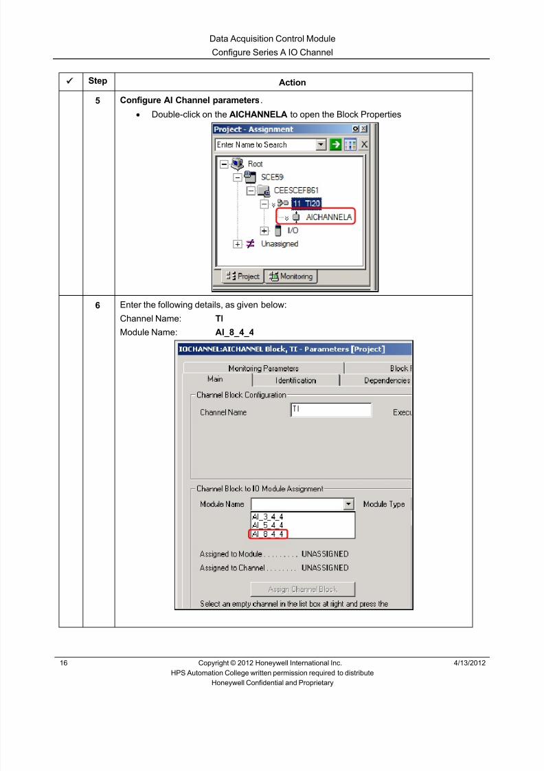
8/9/2019 Student Course Book- Automation
http://slidepdf.com/reader/full/student-course-book-automation 316/1165
Data Acquisition Control Module
Configure Series A IO Channel
16 Copyright © 2012 Honeywell International Inc. 4/13/2012
HPS Automation College written permission required to distributeHoneywell Confidential and Proprietary
Step Action
5 Configure AI Channel parameters .• Double-click on the AICHANNELA to open the Block Properties
6 Enter the following details, as given below:
Channel Name: TI
Module Name: AI_8_4_4

8/9/2019 Student Course Book- Automation
http://slidepdf.com/reader/full/student-course-book-automation 317/1165
Data Acquisition Control Module
Configure Series A IO Channel
4/13/2012 Copyright © 2012 Honeywell International Inc. 17
HPS Automation College written permission required to distributeHoneywell Confidential and Proprietary
Step Action
7 Enter the following details as given below:
Select Channel Number : 1
Click the Assign Channel Block button.
ATTENTION
The Module Type displays automatically when
selecting the module name.
11_TI20.TI is assigned to the channel number 1 of AI_8_4_4, as seen in the ChannelNumber/Channel Name list.
8 Click OK.

8/9/2019 Student Course Book- Automation
http://slidepdf.com/reader/full/student-course-book-automation 318/1165
Data Acquisition Control Module
Configure Series A IO Channel
18 Copyright © 2012 Honeywell International Inc. 4/13/2012
HPS Automation College written permission required to distributeHoneywell Confidential and Proprietary
Step Action
9
ATTENTION
You have completed this section of the lab. Go to thethird section of this lab which is titled ‘Configure theData Acquition Control Module’.
Do NOT perform the section titled ‘Configure Series CI/O Channel’.
10 Save and close 11_TI20.

8/9/2019 Student Course Book- Automation
http://slidepdf.com/reader/full/student-course-book-automation 319/1165
Data Acquisition Control Module
Configure Series C IO Channel
4/13/2012 Copyright © 2012 Honeywell International Inc. 19
HPS Automation College written permission required to distributeHoneywell Confidential and Proprietary
Configure Series C IO Channel
Practice
Objective
• Configure a Control Module (CM)
• Understand the naming of the Control Module and the function blocks within the ControlModule
• Configure an indicator Control Module for an analog input point
• Refer Guide to Debutanizer model for C200/C300 Labs section in Appendix for IOchannel assignment.
Prerequisites
• Experion PKS Server or Client machine with Experion PKS Engineering Tools loaded
• Debutanizer_123 graphic loaded on the server (This is required at a later time to check thecontrol strategy.)
• SIM-C300/C300 Controller and IOMs configured
• Excel Data Exchange configured and loaded with the simulation spreadsheet
Introduction
To create a Control Strategy, you must first create a Control Module, and then insert and connectfunction blocks into the Control Module. The point 11_TI20 is built in this lab. 11_TI20 will havealarming and be in a group and detail display. 11_TI20 will also be historized.
The Control Module is built, loaded and activated. The CM is linked to a Microsoft Excelworksheet for process simulation. The remaining Control Modules of a similar type are thenimported into the project.

8/9/2019 Student Course Book- Automation
http://slidepdf.com/reader/full/student-course-book-automation 320/1165
Data Acquisition Control Module
Configure Series C IO Channel
20 Copyright © 2012 Honeywell International Inc. 4/13/2012
HPS Automation College written permission required to distributeHoneywell Confidential and Proprietary
Configure a Control Module (CM)
Step Action
1 Read the attention box.
ATTENTION
This section should be done only by students whohave selected C300 (and Series C I/O Modules).
2 Open Control Builder through Configuration Studio.• Open one or two Project/Monitor tree windows as desired.
3 Open the Excel spread sheet by double-clicking on:
C:\Users\Student\Documents\Tie_back_NEW.xls
(or by double clicking the shortcut on the desktop if it is available).
Project Tree window
Library Treewindow
MonitoringTree window

8/9/2019 Student Course Book- Automation
http://slidepdf.com/reader/full/student-course-book-automation 321/1165
Data Acquisition Control Module
Configure Series C IO Channel
4/13/2012 Copyright © 2012 Honeywell International Inc. 21
HPS Automation College written permission required to distributeHoneywell Confidential and Proprietary
Step Action
4 From Control Builder expand System in the Library tab, as indicated.

8/9/2019 Student Course Book- Automation
http://slidepdf.com/reader/full/student-course-book-automation 322/1165
Data Acquisition Control Module
Configure Series C IO Channel
22 Copyright © 2012 Honeywell International Inc. 4/13/2012
HPS Automation College written permission required to distributeHoneywell Confidential and Proprietary
Step Action
5 Select and drag the CONTROLMODULE into a blank area in the Project tree.
A dialog box, as seen below, will appear.
ATTENTION
If you have a problem finding blank space which willallow you to drop the CM, collapse the trees in theProject window.
It is important to use the CM names given in thisdocument, because they are used in the Excelsimulation.

8/9/2019 Student Course Book- Automation
http://slidepdf.com/reader/full/student-course-book-automation 323/1165
Data Acquisition Control Module
Configure Series C IO Channel
4/13/2012 Copyright © 2012 Honeywell International Inc. 23
HPS Automation College written permission required to distributeHoneywell Confidential and Proprietary
Step Action
6 Enter the following information:
Destination Tagnames: 11_TI20 (name of the new CM)
Destination Item Names: 11_TI20_Item.
Click Finish .
ATTENTION
In this tagname, the character after the letter T is the letter I.
When adding a new CM, Control Builder numbers the CMsequentially, by default. You can assign any 16-characterunique Project name to the CM.
It is important to use the CM names, given in this document,because they are used in the Excel simulation.
The Source Names contain random numbers generated byControl Builder. Therefore, the ones in this picture may bedifferent than yours.

8/9/2019 Student Course Book- Automation
http://slidepdf.com/reader/full/student-course-book-automation 324/1165
Data Acquisition Control Module
Configure Series C IO Channel
24 Copyright © 2012 Honeywell International Inc. 4/13/2012
HPS Automation College written permission required to distributeHoneywell Confidential and Proprietary
Step Action
7 Verify 11_TI20 is added to the Unassigned section in the Project Tree window.
8 Configure the parameters for 11_TI20.• Right-click 11_TI20 • Select Module Properties
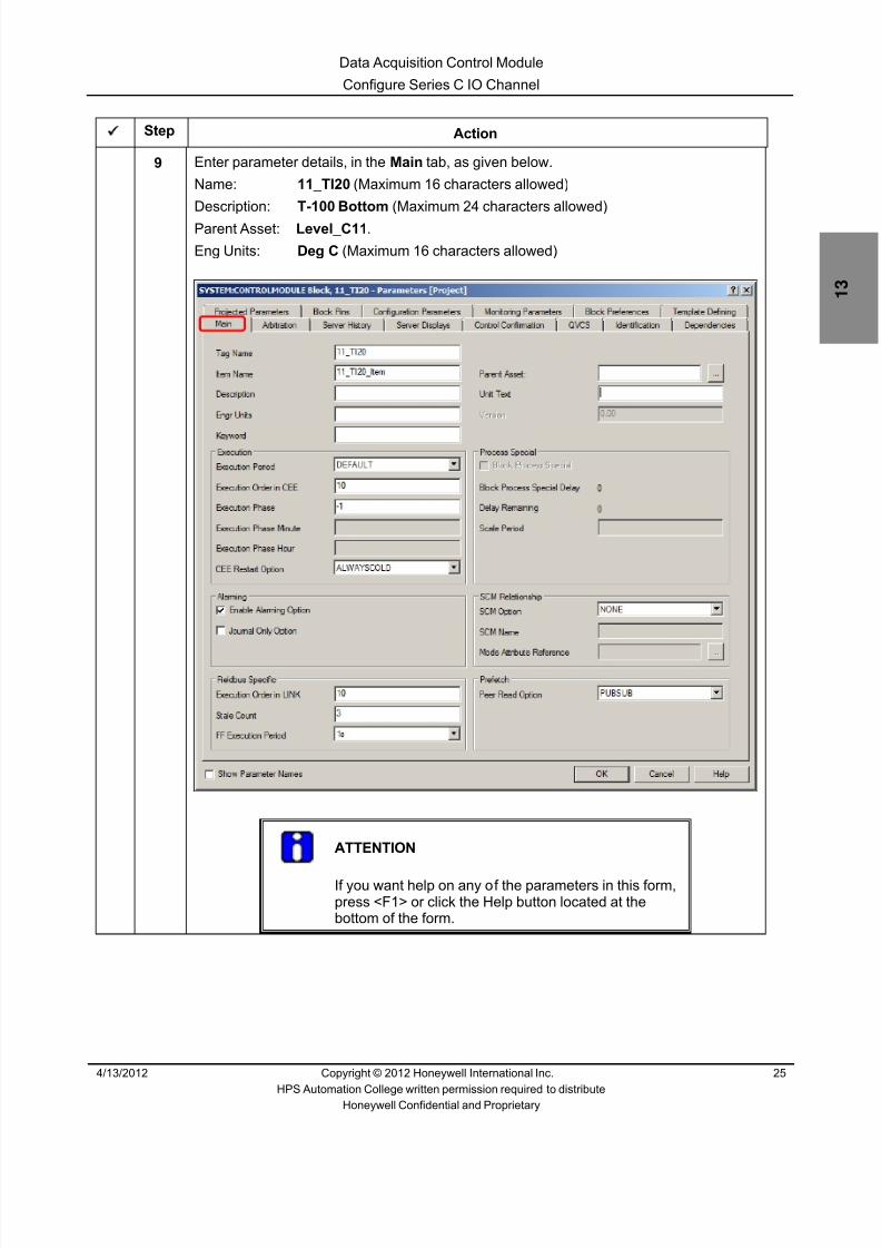
8/9/2019 Student Course Book- Automation
http://slidepdf.com/reader/full/student-course-book-automation 325/1165
Data Acquisition Control Module
Configure Series C IO Channel
4/13/2012 Copyright © 2012 Honeywell International Inc. 25
HPS Automation College written permission required to distributeHoneywell Confidential and Proprietary
Step Action
9 Enter parameter details, in the Main tab, as given below.
Name: 11_TI20 (Maximum 16 characters allowed)
Description: T-100 Bottom (Maximum 24 characters allowed)
Parent Asset: Level_C11 .
Eng Units: Deg C (Maximum 16 characters allowed)
ATTENTION
If you want help on any of the parameters in this form,press <F1> or click the Help button located at thebottom of the form.

8/9/2019 Student Course Book- Automation
http://slidepdf.com/reader/full/student-course-book-automation 326/1165
Data Acquisition Control Module
Configure Series C IO Channel
26 Copyright © 2012 Honeywell International Inc. 4/13/2012
HPS Automation College written permission required to distributeHoneywell Confidential and Proprietary
Step Action
10 Click the Server Displays tab, and enter the display details, as shown below.
ATTENTION
This lab uses the standard Honeywell analog point detail and groupdisplay for the point 11_TI20 in Station.
11 Click OK .
12 Assign the CM to the Controller SIM_CEEC300 .• With 11_TI20 selected, click the Assign Button on the toolbar to open the
Execution Environment Assignment screen• If not already highlighted, select 11_TI20 in the CM/SCMs tab.• Select SIM_CEEC300 in the Assign To window• Click the Assign Button

8/9/2019 Student Course Book- Automation
http://slidepdf.com/reader/full/student-course-book-automation 327/1165
Data Acquisition Control Module
Configure Series C IO Channel
4/13/2012 Copyright © 2012 Honeywell International Inc. 27
HPS Automation College written permission required to distributeHoneywell Confidential and Proprietary
Step Action
13 Assigned Modules will show 11_TI20 .
Click the Close Button.
14 11_TI20 is assigned to SIM_CEEC300, as indicated below.

8/9/2019 Student Course Book- Automation
http://slidepdf.com/reader/full/student-course-book-automation 328/1165
Data Acquisition Control Module
Configure Series C IO Channel
28 Copyright © 2012 Honeywell International Inc. 4/13/2012
HPS Automation College written permission required to distributeHoneywell Confidential and Proprietary
Add Function Blocks to a CM
Use the IOMs, configured in the lab “Configure C300/SIM C300 Hardware”, here.
Step Action1 Double click 11_TI20 in the Project Tree window to open the chart view.
ATTENTION
Your screen may vary from the example shown.

8/9/2019 Student Course Book- Automation
http://slidepdf.com/reader/full/student-course-book-automation 329/1165
Data Acquisition Control Module
Configure Series C IO Channel
4/13/2012 Copyright © 2012 Honeywell International Inc. 29
HPS Automation College written permission required to distributeHoneywell Confidential and Proprietary
Step Action
2 Add Function Blocks to CM 11_TI20.• Select the Series_C_IOLINK Link• Expand the C_AI_3, by clicking the ‘+’ sign adjacent to it• Select the AICHANNEL_01 block
ATTENTION
You can add Series C IO function blocks to a CM in two ways:
1. The Project Tree method.2. The Library Tree method (Covered in Describe C300 and
Series C IO configuration Presentation)
We will use the Project Tree method. This method uses thefact that Series C IO modules contain their own configurationdatabases. Therefore when you add an IOM, its configurationparameters are available from project.
In this case, select the first AI channel from your AI IOM.
Refer Guide to Debutanizer model for C200/C300 Labssection in Appendix for IO channel assignment

8/9/2019 Student Course Book- Automation
http://slidepdf.com/reader/full/student-course-book-automation 330/1165
Data Acquisition Control Module
Configure Series C IO Channel
30 Copyright © 2012 Honeywell International Inc. 4/13/2012
HPS Automation College written permission required to distributeHoneywell Confidential and Proprietary
Step Action
3 Drag and drop the AICHANNEL_01 onto 11_TI20 chart view.
4Click the icon on the toolbar to Save your CM to the Project database.
5 Configure AI Channel parameters .• Double click on the AICHANNEL_01 from the chart view of 11_TI20.
6 Enter the following details, as given below:
Channel Name: TI
ATTENTION
IO Channel is automatically assigned to the IOM when you drag anddrop it from the IOLINK.

8/9/2019 Student Course Book- Automation
http://slidepdf.com/reader/full/student-course-book-automation 331/1165
Data Acquisition Control Module
Configure Series C IO Channel
4/13/2012 Copyright © 2012 Honeywell International Inc. 31
HPS Automation College written permission required to distributeHoneywell Confidential and Proprietary
Step Action
7 Click on the Configuration tab and enter the Channel PV Ranges details as givenbelow:
• PV Extended High Range: 267.54 • PV High Range: 260 • PV Low Range: 0 • PV Extended Low Range: - 7.54
ATTENTION
In all Labs, you need to configure the Channel PVRange parameters for all Analog Input Channelblocks; it should match with DACA block ProcessVariable details.
Click OK 8 Save and close 11_TI20.
9
TIP
In the future, when building Control Modules, follow thesteps above.

8/9/2019 Student Course Book- Automation
http://slidepdf.com/reader/full/student-course-book-automation 332/1165
Data Acquisition Control Module
Configure Series C IO Channel
32 Copyright © 2012 Honeywell International Inc. 4/13/2012
HPS Automation College written permission required to distributeHoneywell Confidential and Proprietary
This page was intentionally left blank.

8/9/2019 Student Course Book- Automation
http://slidepdf.com/reader/full/student-course-book-automation 333/1165
Data Acquisition Control Module
Configure the Data Acquisition Control Module
4/13/2012 Copyright © 2012 Honeywell International Inc. 33
HPS Automation College written permission required to distributeHoneywell Confidential and Proprietary
Configure the Data Acquisition Control Module
Practice
Objective
• Configure a Data Acquisition Control Module (CM)
• Understand the naming of the Control Module and the function blocks within the ControlModule
Prerequisites
• Experion PKS Server or Client machine with Experion PKS Engineering Tools loaded
• Debutanizer_123 graphic loaded on the server (This is required at a later time to check thecontrol strategy.)
• SIM C200E/C200E, or C300/SIM-C300 Controller and IOMs configured
• Excel Data Exchange configured and loaded with the simulation spreadsheet
Introduction
To create a Control Strategy, you must first create a Control Module, and then insert and connectfunction blocks into the Control Module. The point 11_TI20 is built in this lab. 11_TI20 will havealarming and be in a group and detail display. 11_TI20 will also be historized.
The Control Module is built, loaded and activated. The CM is linked to a Microsoft Excelworksheet for process simulation. The remaining Control Modules of a similar type are thenimported into the project.

8/9/2019 Student Course Book- Automation
http://slidepdf.com/reader/full/student-course-book-automation 334/1165
Data Acquisition Control Module
Configure the Data Acquisition Control Module
34 Copyright © 2012 Honeywell International Inc. 4/13/2012
HPS Automation College written permission required to distributeHoneywell Confidential and Proprietary
Add Function Blocks to a CM
Use the IOMs, configured in the lab “Controller Hardware Configuration”, here.
Step Action
1 Read the attention box.
ATTENTION
This section should be done ALL students (C200E &C300).
2 Open Control Builder and open 11_TI20 to the chart view.3 Add a DACA Function Block to CM 11_TI20.
• Click the Library Tree window• Expand the DATAACQ, by clicking the ‘+’ sign adjacent to it• Select the DATAACQ block• Drag and drop the DATAACQ block on the 11_TI20 chart view.
ATTENTION
For more information on adding function blocks to aCM, refer to the Control Building Guide in KnowledgeBuilder along the path,Experion R400 > Configuration > Control Buildingusers Guide > Creating a Control Module >Creating an Instance of a Basic Function Block.

8/9/2019 Student Course Book- Automation
http://slidepdf.com/reader/full/student-course-book-automation 335/1165
Data Acquisition Control Module
Configure the Data Acquisition Control Module
4/13/2012 Copyright © 2012 Honeywell International Inc. 35
HPS Automation College written permission required to distributeHoneywell Confidential and Proprietary
Step Action
4 Maximize the chart view by clicking the icon.

8/9/2019 Student Course Book- Automation
http://slidepdf.com/reader/full/student-course-book-automation 336/1165
Data Acquisition Control Module
Configure the Data Acquisition Control Module
36 Copyright © 2012 Honeywell International Inc. 4/13/2012
HPS Automation College written permission required to distributeHoneywell Confidential and Proprietary
Step Action
5 Arrange the blocks as shown below.
ATTENTION
In this lab the screen capture is shown forSIMC200E/C200E, if you are using SIMC300/C300 the
AI channel will be different from Series A.

8/9/2019 Student Course Book- Automation
http://slidepdf.com/reader/full/student-course-book-automation 337/1165
Data Acquisition Control Module
Configure the Data Acquisition Control Module
4/13/2012 Copyright © 2012 Honeywell International Inc. 37
HPS Automation College written permission required to distributeHoneywell Confidential and Proprietary
Step Action
6Click the icon on the toolbar to Save your CM to the Project database.
7 Double-click the Data Acquisition Block that was just added to the CM.
8 Enter the following information :
Name: DACA
Description: T-100 Bottoms
Engr Units: Deg C
ATTENTION
This block must be named DACA so that theHoneywell supplied analog point detail display willfunction properly when called from Station.

8/9/2019 Student Course Book- Automation
http://slidepdf.com/reader/full/student-course-book-automation 338/1165
Data Acquisition Control Module
Configure the Data Acquisition Control Module
38 Copyright © 2012 Honeywell International Inc. 4/13/2012
HPS Automation College written permission required to distributeHoneywell Confidential and Proprietary
Step Action
9 Enter the Process Variable details, as given below:
• PVEU Range Hi: 260 • PVEU Range Lo: 0 • PV Extended Hi Limit: 267.54 • PV Extended Lo Limit: -7.54 • Low Signal Cut Off: NaN
10 Enable Clamping Option .

8/9/2019 Student Course Book- Automation
http://slidepdf.com/reader/full/student-course-book-automation 339/1165
Data Acquisition Control Module
Configure the Data Acquisition Control Module
4/13/2012 Copyright © 2012 Honeywell International Inc. 39
HPS Automation College written permission required to distributeHoneywell Confidential and Proprietary
Step Action
11
ATTENTION
The PV High must set before the PV High High willappear.
Configure Alarms for the CM.• Click the Alarms Tab of the DACA Block• Enter the information as given below :
Trip Point Priority
PV High High 260 URGENT
PV High 234 HIGH
PV Low 13 LOW
12 Click OK .

8/9/2019 Student Course Book- Automation
http://slidepdf.com/reader/full/student-course-book-automation 340/1165
Data Acquisition Control Module
Configure the Data Acquisition Control Module
40 Copyright © 2012 Honeywell International Inc. 4/13/2012
HPS Automation College written permission required to distributeHoneywell Confidential and Proprietary
Connect Function Blocks
After adding the Function Blocks, connect them together to form a control strategy. Connect Blockstogether anytime, before or after configuring block parameters.
Step Action
1Select Chart > Insert > Wire or click icon in the toolbar.
• Cursor changes to PLUS “+” sign inside the Project chart window• Click the PV Pin of AICHANNEL block (TI)
ATTENTION
Note the change in color for the PV pin of block TI.This indicates the block pin is selected.
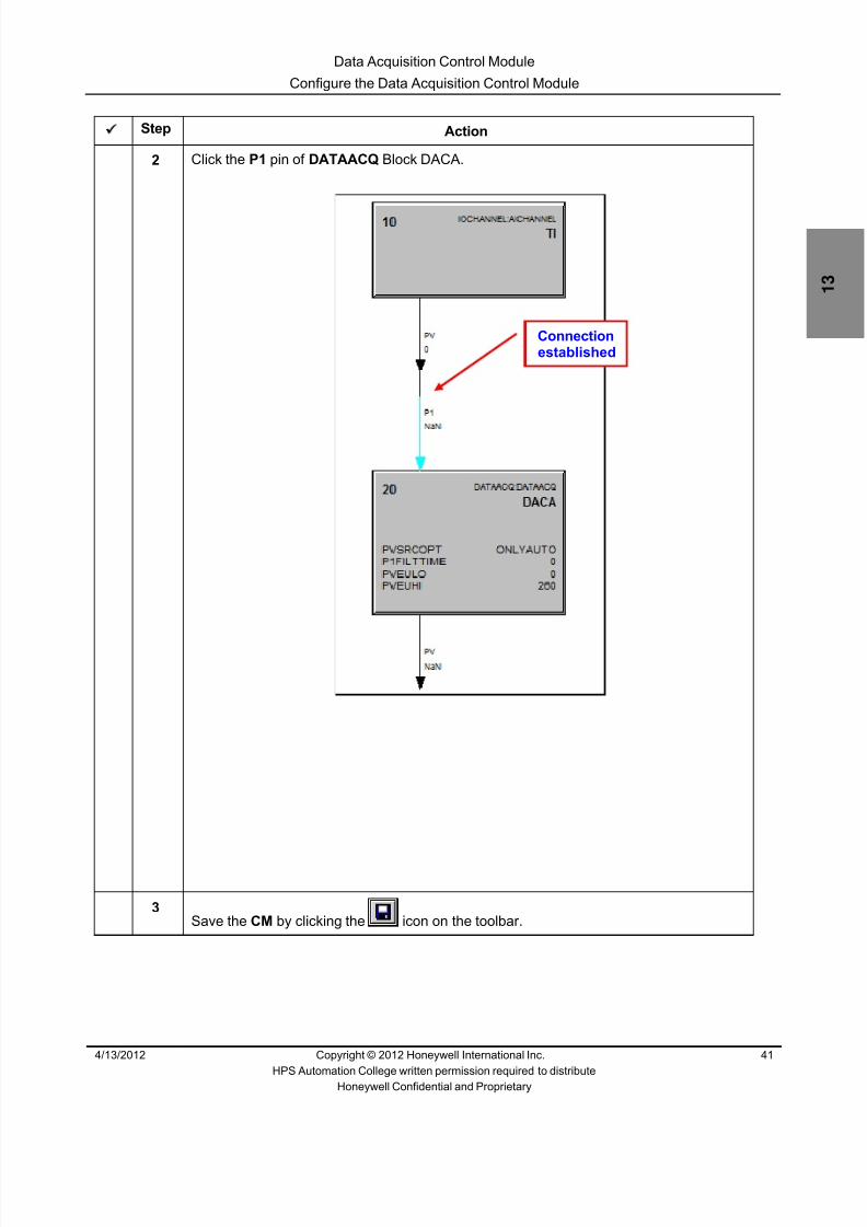
8/9/2019 Student Course Book- Automation
http://slidepdf.com/reader/full/student-course-book-automation 341/1165
Data Acquisition Control Module
Configure the Data Acquisition Control Module
4/13/2012 Copyright © 2012 Honeywell International Inc. 41
HPS Automation College written permission required to distributeHoneywell Confidential and Proprietary
Step Action
2 Click the P1 pin of DATAACQ Block DACA.
3Save the CM by clicking the icon on the toolbar.
Connectionestablished

8/9/2019 Student Course Book- Automation
http://slidepdf.com/reader/full/student-course-book-automation 342/1165
Data Acquisition Control Module
Configure the Data Acquisition Control Module
42 Copyright © 2012 Honeywell International Inc. 4/13/2012
HPS Automation College written permission required to distributeHoneywell Confidential and Proprietary
Step Action
4 To show the cross reference connections made between function blocks:• Click Tools > System Preferences to open the window, as shown in the display
below• Select the Display Cross-References checkbox under the General tab.• Click OK

8/9/2019 Student Course Book- Automation
http://slidepdf.com/reader/full/student-course-book-automation 343/1165
Data Acquisition Control Module
Configure the Data Acquisition Control Module
4/13/2012 Copyright © 2012 Honeywell International Inc. 43
HPS Automation College written permission required to distributeHoneywell Confidential and Proprietary
Step Action
5 Click OK . (Your dialog box may not look exactly like this one.)

8/9/2019 Student Course Book- Automation
http://slidepdf.com/reader/full/student-course-book-automation 344/1165
Data Acquisition Control Module
Configure the Data Acquisition Control Module
44 Copyright © 2012 Honeywell International Inc. 4/13/2012
HPS Automation College written permission required to distributeHoneywell Confidential and Proprietary
Step Action
6 The display below shows cross references .
TIP
This cross reference may not be shown on a C300Control Module

8/9/2019 Student Course Book- Automation
http://slidepdf.com/reader/full/student-course-book-automation 345/1165
Data Acquisition Control Module
Configure the Data Acquisition Control Module
4/13/2012 Copyright © 2012 Honeywell International Inc. 45
HPS Automation College written permission required to distributeHoneywell Confidential and Proprietary
Step Action
7 History collection .• Double-click CM 11_TI20 in the white space to open the configuration form• Click the Server History tab. Verify that the Control Level is 200
8 Select the parameters for historization .• Click the blank Row 1 under the Parameter column in the History
Configuration table
• Click the Point selection button to open the Point Selection form

8/9/2019 Student Course Book- Automation
http://slidepdf.com/reader/full/student-course-book-automation 346/1165
Data Acquisition Control Module
Configure the Data Acquisition Control Module
46 Copyright © 2012 Honeywell International Inc. 4/13/2012
HPS Automation College written permission required to distributeHoneywell Confidential and Proprietary
Step Action
9 The Point Selection form appears, as shown below.
Select Point 11_TI20 DACA, as indicated below.
Select parameter PV from the Parameters of 11_TI20.DACA list.
Click OK to close the Point Selection form.
10 11_TI20.DACA.PV appears in the History Configuration table.• Select the FAST and STD history checkboxes

8/9/2019 Student Course Book- Automation
http://slidepdf.com/reader/full/student-course-book-automation 347/1165
Data Acquisition Control Module
Configure the Data Acquisition Control Module
4/13/2012 Copyright © 2012 Honeywell International Inc. 47
HPS Automation College written permission required to distributeHoneywell Confidential and Proprietary
Step Action
11 Click the Server Displays tab and enter the following information, to add the CM to aTrend and Group.
ATTENTION
You can also do this, by entering the trend/groupnumber and the pen/ position, in the trend and groupwindow, after building the control strategy in the CM.
12 Click OK to close the Control Module Properties window.
Number of trendsto be entered
Enter Trend #, Pencolor, Parameter andDescription.
Enter Group #, Positionof the tag in the group,Parameter andDescription.

8/9/2019 Student Course Book- Automation
http://slidepdf.com/reader/full/student-course-book-automation 348/1165
Data Acquisition Control Module
Configure the Data Acquisition Control Module
48 Copyright © 2012 Honeywell International Inc. 4/13/2012
HPS Automation College written permission required to distributeHoneywell Confidential and Proprietary
Step Action
13 Save the CM 11_TI20 and close the chart window.
• This CM now appears with the symbol “ “indicating that the CM has not yetbeen loaded to the controller
14 Download this CM.• Select 11_TI20
• Click the button on the toolbar• Select Continue in the Load Box
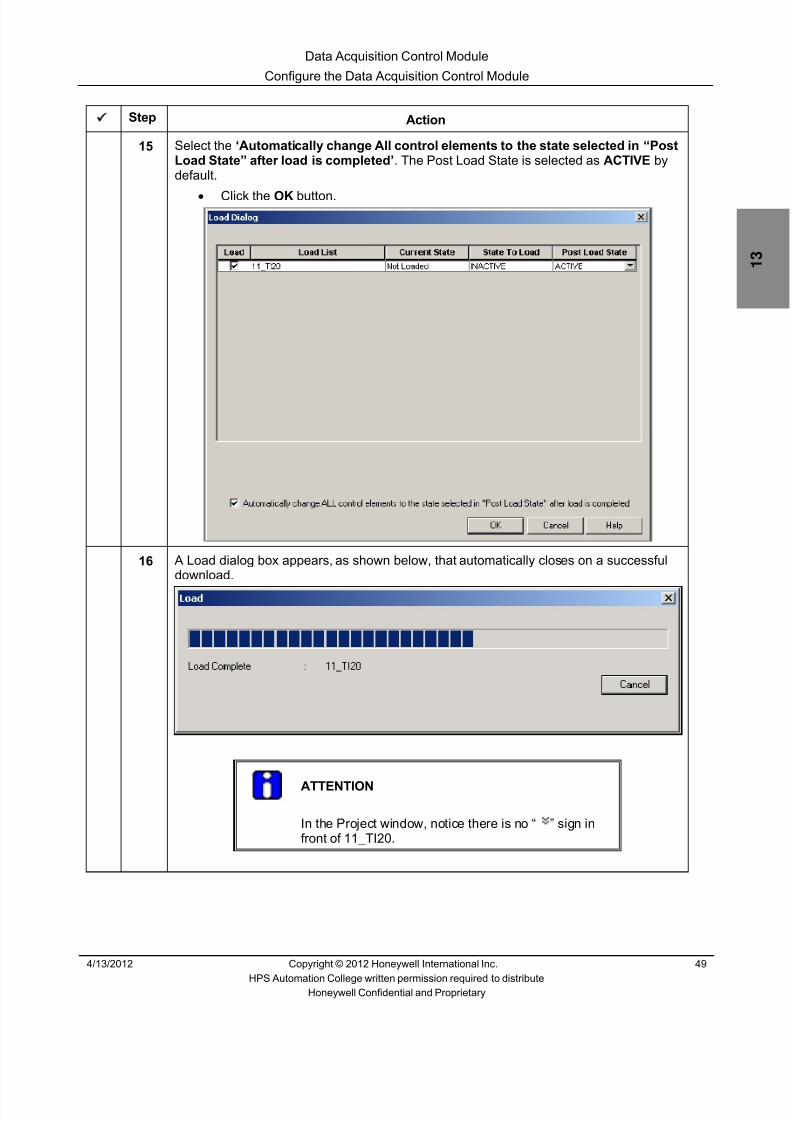
8/9/2019 Student Course Book- Automation
http://slidepdf.com/reader/full/student-course-book-automation 349/1165

8/9/2019 Student Course Book- Automation
http://slidepdf.com/reader/full/student-course-book-automation 350/1165
Data Acquisition Control Module
Configure the Data Acquisition Control Module
50 Copyright © 2012 Honeywell International Inc. 4/13/2012
HPS Automation College written permission required to distributeHoneywell Confidential and Proprietary
Step Action
17 Click the Monitoring Tree window to verify that 11_TI20 is green, which means it isactive.
1 If active (green) skip the next step
2 If inactive (blue) perform the next step
18 Activate the CM. To activate a CM, right-click and select “ Activate > Selected Items ”or select 11_TI20, and click the Toggle State button on the toolbar.
1 The following screen appears
Click Yes .
2 Notice 11_TI20 is now green
19 Open Station, if not already open.

8/9/2019 Student Course Book- Automation
http://slidepdf.com/reader/full/student-course-book-automation 351/1165
Data Acquisition Control Module
Configure the Data Acquisition Control Module
4/13/2012 Copyright © 2012 Honeywell International Inc. 51
HPS Automation College written permission required to distributeHoneywell Confidential and Proprietary
Step Action
20 Call up Debutanizer_123 on Station, as shown below.
The 11_TI20 point is at the bottom of the T-100 tower.
In this example, the temperature shown is approximately 85.00 DegC.
If you click the parameter block in your graphic, point parameter, details appear in themessage zone: E20ESV##_Server:11_TI20.DACA.PV with real-time value and the CMdescription.
ATTENTION
If you do not see the value for 11_TI20 varying, thenclose and open the Tie_back_new.xls file.
Use this file for simulation purpose.
E20ESV##_Server is the server alias name definedfor this class. In real environment this will be a differentname specific to your site requirements.
The ## is the student number

8/9/2019 Student Course Book- Automation
http://slidepdf.com/reader/full/student-course-book-automation 352/1165
Data Acquisition Control Module
Configure the Data Acquisition Control Module
52 Copyright © 2012 Honeywell International Inc. 4/13/2012
HPS Automation College written permission required to distributeHoneywell Confidential and Proprietary
Step Action
21
ATTENTION
The actual value may be different on your screen.
If the 11_TI20 CM is inactive, the value in theparameter box is NaN .
If a point is not properly built and you select theparameter block, the following message appears in themessage zone: “Selected object not found”.
If the point is not loaded and you select the parameterblock, the following message appears:11_TI20.DACA.PV=??().

8/9/2019 Student Course Book- Automation
http://slidepdf.com/reader/full/student-course-book-automation 353/1165
1
1
Honeywell ConfidentialCopyright © 2012 Honeywell International Inc.
4/13/2012
Describe Bulk Build Functionality
Productivity Tools in Control Builder Describe Bulk Build FunctionalityProductivity Tools in Control Builder Describe Bulk Build Functionality
Honeywell
Honeywell ConfidentialCopyright © 2012 Honeywell International Inc.
4/13/20122
Introduction
• In this lesson, you will learn to use the Bulk Build tool inControl Builder.
• At the conclusion of this lesson, you will be able to describe how toquickly build multiple control modules of the same type using theBulk Build tool.
Productivity Tools in Control Builder Describe Bulk Build Functionality

8/9/2019 Student Course Book- Automation
http://slidepdf.com/reader/full/student-course-book-automation 354/1165
2
Honeywell
Honeywell ConfidentialCopyright © 2012 Honeywell International Inc.
4/13/20123
Topics
• Bulk Build Procedure Overview• Bulk Build Procedure
Productivity Tools in Control Builder Describe Bulk Build Functionality
Honeywell
Honeywell ConfidentialCopyright © 2012 Honeywell International Inc.
4/13/20124
Overview of the Bulk Build ProcedureCreateTypical(s)
Select Typical(s)Tool: Create Bulk Build List
For each typical:Determine the number ofthe names of the copies
For each typical:Select the parameters tobe changed on the copies
Create the Bulk Build file.mdb, .csv, .xls
Edit the Bulk Build file –parameters to change onthe copies
Read the Bulk Build fileTool: Read Bulk Build List
Build Copies
1 2
3
4
5
6 7
8
Productivity Tools in Control Builder Describe Bulk Build Functionality
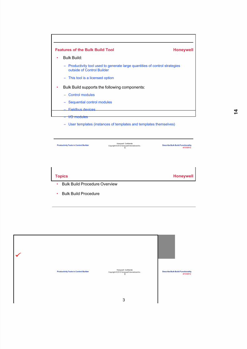
8/9/2019 Student Course Book- Automation
http://slidepdf.com/reader/full/student-course-book-automation 355/1165
3
Honeywell
Honeywell ConfidentialCopyright © 2012 Honeywell International Inc.
4/13/20125
Features of the Bulk Build Tool
• Bulk Build:
– Productivity tool used to generate large quantities of control strategiesoutside of Control Builder
– This tool is a licensed option
• Bulk Build supports the following components:
– Control modules
– Sequential control modules
– Fieldbus devices
– I/O modules
– User templates (instances of templates and templates themselves)
Productivity Tools in Control Builder Describe Bulk Build Functionality
Honeywell
Honeywell ConfidentialCopyright © 2012 Honeywell International Inc.
4/13/20126
Topics
• Bulk Build Procedure Overview
• Bulk Build Procedure
Productivity Tools in Control Builder Describe Bulk Build Functionality

8/9/2019 Student Course Book- Automation
http://slidepdf.com/reader/full/student-course-book-automation 356/1165
4
Honeywell
Honeywell ConfidentialCopyright © 2012 Honeywell International Inc.
4/13/20127
Create the Bulk Build List
Invoke CreateBulk Build List
Tools > Bulk Build > Create Bulk Build List
Productivity Tools in Control Builder Describe Bulk Build Functionality
Honeywell
Honeywell ConfidentialCopyright © 2012 Honeywell International Inc.
4/13/20128
Select a Typical Control Strategy
Set copy nameand count
Select a typicalcontrol strategy
Productivity Tools in Control Builder Describe Bulk Build Functionality
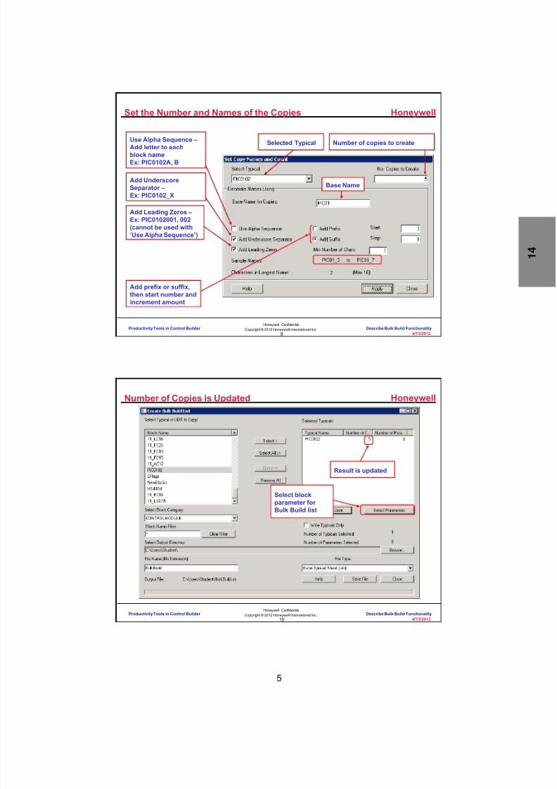
8/9/2019 Student Course Book- Automation
http://slidepdf.com/reader/full/student-course-book-automation 357/1165
5
Honeywell
Honeywell ConfidentialCopyright © 2012 Honeywell International Inc.
4/13/20129
Set the Number and Names of the Copies
Number of copies to create
Add Leading Zeros –Ex: PIC0102001, 002(cannot be used with‘Use Alpha Sequence’)
Use Alpha Sequence –Add letter to eachblock nameEx: PIC0102A, B
Add UnderscoreSeparator –Ex: PIC0102_X
Add prefix or suffix,then start number andincrement amount
Selected Typical
Base Name
Productivity Tools in Control Builder Describe Bulk Build Functionality
Honeywell
Honeywell ConfidentialCopyright © 2012 Honeywell International Inc.
4/13/201210
Number of Copies is Updated
Result is updated
Select blockparameter forBulk Build list
Productivity Tools in Control Builder Describe Bulk Build Functionality

8/9/2019 Student Course Book- Automation
http://slidepdf.com/reader/full/student-course-book-automation 358/1165
6
Honeywell
Honeywell ConfidentialCopyright © 2012 Honeywell International Inc.
4/13/201211
Select Parameters
Select block
Parameters ofselected block Parameters selected
for typical controlstrategy
Productivity Tools in Control Builder Describe Bulk Build Functionality
Honeywell
Honeywell ConfidentialCopyright © 2012 Honeywell International Inc.
4/13/201212
Number of Parameters is Updated
Result is updated
Productivity Tools in Control Builder Describe Bulk Build Functionality

8/9/2019 Student Course Book- Automation
http://slidepdf.com/reader/full/student-course-book-automation 359/1165
7
Honeywell
Honeywell ConfidentialCopyright © 2012 Honeywell International Inc.
4/13/201213
Modify Parameters in Excel
Make modificationsas desired in therequired CM
Productivity Tools in Control Builder Describe Bulk Build Functionality
Honeywell
Honeywell ConfidentialCopyright © 2012 Honeywell International Inc.
4/13/201214
Open the ‘Read Bulk Build List’ Tool
Tools > Bulk Build > Read Bulk Build List
Invoke ReadBulk Build List
Productivity Tools in Control Builder Describe Bulk Build Functionality

8/9/2019 Student Course Book- Automation
http://slidepdf.com/reader/full/student-course-book-automation 360/1165
8
Honeywell
Honeywell ConfidentialCopyright © 2012 Honeywell International Inc.
4/13/201215
Read Excel File and Validate Control Strategies
Select to replaceexisting, when desired
Select Validate
Validation ensures thatthe Typicals being copied
are present and arestructurally consistentwith the spreadsheet
Productivity Tools in Control Builder Describe Bulk Build Functionality
Honeywell
Honeywell ConfidentialCopyright © 2012 Honeywell International Inc.
4/13/201216
Validation Report
Productivity Tools in Control Builder Describe Bulk Build Functionality

8/9/2019 Student Course Book- Automation
http://slidepdf.com/reader/full/student-course-book-automation 361/1165
9
Honeywell
Honeywell ConfidentialCopyright © 2012 Honeywell International Inc.
4/13/201217
Build Control Strategies
Select Build
Validated….
Build OK….
Build and Assign OK….
Productivity Tools in Control Builder Describe Bulk Build Functionality
Honeywell
Honeywell ConfidentialCopyright © 2012 Honeywell International Inc.
4/13/201218
Build Report
View reportafter Bulk Build
Productivity Tools in Control Builder Describe Bulk Build Functionality

8/9/2019 Student Course Book- Automation
http://slidepdf.com/reader/full/student-course-book-automation 362/1165
10
Honeywell
Honeywell ConfidentialCopyright © 2012 Honeywell International Inc.
4/13/201219
New CMs
New CMs availablein the Project
Productivity Tools in Control Builder Describe Bulk Build Functionality
Honeywell
Honeywell ConfidentialCopyright © 2012 Honeywell International Inc.
4/13/201220
Question 1: Bulk Build Tool
Incorrect. The Bulk Build tool is used to generatemultiple control strategies outside Control Builder.
Click anywhere to continue.
Correct! The Bulk Build tool is used to generatemultiple control strategies outside Control Builder.
Click anywhere to continue.
Incorrect. The Bulk Build tool is used to generatemultiple control strategies outside Control Builder.
Click anywhere to continue.
Incorrect. The Bulk Build tool is used to generatemultiple control strategies outside Control Builder.
Click anywhere to continue.
Correct - Click anywhere to continueIncorrect - Click anywhere to continueYou answered this correctly!
Your answer: The correct answer is:
You did not answer this question completelyYou must answer the question beforecontinuing
Submit Clear
Use the Bulk Build tool to: A) Create EB files for C200/C300
control modules
B) Generate large quantities of control strategies outside ControlBuilder
C) Export control modules to otherERDBs
D) All of the above
Productivity Tools in Control Builder Describe Bulk Build Functionality

8/9/2019 Student Course Book- Automation
http://slidepdf.com/reader/full/student-course-book-automation 363/1165
11
Honeywell
Honeywell ConfidentialCopyright © 2012 Honeywell International Inc.
4/13/201221
Summary
• The Bulk Build tool:
– Exports multiple copies of a typical control strategy to an Excel spreadsheetwhere each copy can be modified.
– Imports the edited Excel spreadsheet back into Control Builder which appliesthe normal configuration checks and creates the individual control strategies.
– Supports the following components
• Control modules
• Sequential control modules
• Fieldbus devices
• I/O modules
• User templates (instances of templates and templates themselves)
Productivity Tools in Control Builder Describe Bulk Build Functionality
Honeywell
Honeywell ConfidentialCopyright © 2012 Honeywell International Inc.
4/13/201222
Conclusion
Describe Bulk Build Functionality
CompletionCertificate
Proceed to the next lesson in your course material.
Productivity Tools in Control Builder Describe Bulk Build Functionality

8/9/2019 Student Course Book- Automation
http://slidepdf.com/reader/full/student-course-book-automation 364/1165
12
23
Honeywell ConfidentialCopyright © 2012 Honeywell International Inc.
4/13/2012
Describe Bulk Edit Parameters Functionality
Productivity Tools in Control Builder Describe Bulk Edit Parameters FunctionalityProductivity Tools in Control Builder Describe Bulk Edit Parameters Functionality
Honeywell
Honeywell ConfidentialCopyright © 2012 Honeywell International Inc.
4/13/201224
Introduction
• In this lesson you will learn how to use the bulk edit parameters tool inControl Builder.
• At the conclusion of this lesson,you will know how touse the tool to:
– Export tags and parameters froma Control Builder project to anExcel spreadsheet
– Modify the parameters in anExcel spreadsheet
– Read the parameters into aControl Builder project
Productivity Tools in Control Builder Describe Bulk Edit Parameters Functionality

8/9/2019 Student Course Book- Automation
http://slidepdf.com/reader/full/student-course-book-automation 365/1165
13
Honeywell
Honeywell ConfidentialCopyright © 2012 Honeywell International Inc.
4/13/201225
Create Bulk Edit List
• Bulk Edit Parameters
– Utility which allows you to change the value of multiple parameters in asingle operation by importing a prepared list of edits
• Tools > Bulk Edit Parameters > Create Bulk Edit List
Productivity Tools in Control Builder Describe Bulk Edit Parameters Functionality
Honeywell
Honeywell ConfidentialCopyright © 2012 Honeywell International Inc.
4/13/201226
Create Bulk Edit List
• The Show All Points button is used to populate the "Available Points"selection list with the names of all points in the database.
Productivity Tools in Control Builder Describe Bulk Edit Parameters Functionality

8/9/2019 Student Course Book- Automation
http://slidepdf.com/reader/full/student-course-book-automation 366/1165
14
Honeywell
Honeywell ConfidentialCopyright © 2012 Honeywell International Inc.
4/13/201227
Select the Parameters Which Will be Changed
• Select the points and parameters
The selected points
The parameter(s)to be modified
All parameters thatexist on any selected
block in the “AvailablePoints” field will appear
in the “AvailableParameters” field.
Productivity Tools in Control Builder Describe Bulk Edit Parameters Functionality
Honeywell
Honeywell ConfidentialCopyright © 2012 Honeywell International Inc.
4/13/201228
Create Bulk Edit List
• Build the Excel file
Browse todesiredoutput path
Name theoutput file
Select the outputfile type
Save
Productivity Tools in Control Builder Describe Bulk Edit Parameters Functionality

8/9/2019 Student Course Book- Automation
http://slidepdf.com/reader/full/student-course-book-automation 367/1165
15
Honeywell
Honeywell ConfidentialCopyright © 2012 Honeywell International Inc.
4/13/201229
Edit Parameters
• Open the created BulkEdit.xls file in Excel
Use the single quote
before numbers ‘100
Do not change or
add tag names.Keep columns in order.
Edit the parametersas necessary
Productivity Tools in Control Builder Describe Bulk Edit Parameters Functionality
Honeywell
Honeywell ConfidentialCopyright © 2012 Honeywell International Inc.
4/13/201230
Read Bulk Edit List
Select UpdateMonitor or Project Select Start
Productivity Tools in Control Builder Describe Bulk Edit Parameters Functionality

8/9/2019 Student Course Book- Automation
http://slidepdf.com/reader/full/student-course-book-automation 368/1165
16
Honeywell
Honeywell ConfidentialCopyright © 2012 Honeywell International Inc.
4/13/201231
Question 1: Bulk Edit Parameters Tool
Incorrect. The Bulk Edit Parameters tool is used to changeselected parameters in selected control modules.
Click anywhere to continue.
Incorrect. The Bulk Edit Parameters tool is used to changeselected parameters in selected control modules.
Click anywhere to continue.
Incorrect. The Bulk Edit Parameters tool is used to changeselected parameters in selected control modules.
Click anywhere to continue.
Correct! The Bulk Edit Parameters tool is used to changeselected parameters in selected control modules.
Click anywhere to continue.
Correct - Click anywhere to continueIncorrect - Click anywhere to continueYou answered this correctly!Your answer:The correct answer is:You did not answer this question completelyYou must answer the question before
continuing
Submit Clear
Use the bulk edit parameters tool:
A) As an online tool to activate or inactivate multiplecontrol modules at once
B) To copy the control module to the monitoring tab
C) To export selected control modules
D) To change selected parameters in selected controlmodules
Productivity Tools in Control Builder Describe Bulk Edit Parameters Functionality
Honeywell
Honeywell ConfidentialCopyright © 2012 Honeywell International Inc.
4/13/201232
Summary
• You can use the Bulk Edit Parameters tool to:
– Export tags and parameters from a Control Builder project to an Excelspreadsheet.
– Modify the parameters in an Excel spreadsheet.
• Do not change or add tag names
• Keep columns in order
• Use the single quote before numbers ‘100
– Read the parameters into a Control Builder project.
Productivity Tools in Control Builder Describe Bulk Edit Parameters Functionality

8/9/2019 Student Course Book- Automation
http://slidepdf.com/reader/full/student-course-book-automation 369/1165
17
Honeywell
Honeywell ConfidentialCopyright © 2012 Honeywell International Inc.
4/13/201233
Conclusion
Describe Bulk Edit Parameters Functionality
CompletionCertificate
Proceed to the next lesson in your course material.
Productivity Tools in Control Builder Describe Bulk Edit Parameters Functionality
Honeywell
Honeywell ConfidentialCopyright © 2012 Honeywell International Inc.
4/13/201234
This page intentionally left blank
Productivity Tools in Control Builder Describe Bulk Edit Parameters Functionality

8/9/2019 Student Course Book- Automation
http://slidepdf.com/reader/full/student-course-book-automation 370/1165
18
35
Honeywell ConfidentialCopyright © 2012 Honeywell International Inc.
4/13/2012
Describe the Block Name References in CMand SCM
Productivity Tools in Control Builder Describe the Block Name References in CM and SCMProductivity Tools in Control Builder Describe the Block Name References in CM and SCM
Honeywell
Honeywell ConfidentialCopyright © 2012 Honeywell International Inc.
4/13/201236
Introduction
• In this lesson, you will learn about:
– Block name references in CMs and SCMs
• At the conclusion of this lesson, you will be able to:
– Reference a parameter in CMs
– Reference a parameter in SCMs
Productivity Tools in Control Builder Describe the Block Name References in CM and SCM

8/9/2019 Student Course Book- Automation
http://slidepdf.com/reader/full/student-course-book-automation 371/1165
19
Honeywell
Honeywell ConfidentialCopyright © 2012 Honeywell International Inc.
4/13/201237
Name References
• Generally, name references take the following form: – CM_Name.BlockName.Parameter
• EX: 11_PC15.PIDA.SP – SCM_Name.Parameter
• Ex: SCM_D100.ModeAttr • Name references exist in:
– Parameter references
– Expressions used in SCMs
– Expressions used in Calc Blocks
Productivity Tools in Control Builder Describe the Block Name References in CM and SCM
Honeywell
Honeywell ConfidentialCopyright © 2012 Honeywell International Inc.
4/13/201238
System Preferences – Relative Reference Display Option
• Tools>System Preferences• The ‘Relative Reference
Display Option’ allowsreferences to be: – Full Name – Short Name
• Enter less information• Use less area on
chart view• Fewer characters in
expressions
Productivity Tools in Control Builder Describe the Block Name References in CM and SCM
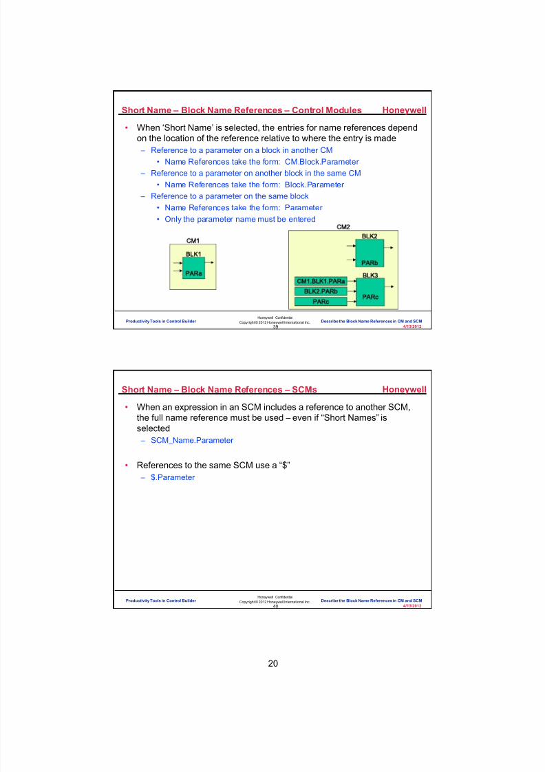
8/9/2019 Student Course Book- Automation
http://slidepdf.com/reader/full/student-course-book-automation 372/1165
20
Honeywell
Honeywell ConfidentialCopyright © 2012 Honeywell International Inc.
4/13/201239
Short Name – Block Name References – Control Modules
• When ‘Short Name’ is selected, the entries for name references dependon the location of the reference relative to where the entry is made – Reference to a parameter on a block in another CM
• Name References take the form: CM.Block.Parameter – Reference to a parameter on another block in the same CM
• Name References take the form: Block.Parameter – Reference to a parameter on the same block
• Name References take the form: Parameter • Only the parameter name must be entered
CM1
BLK1
PARa
CM2BLK2
PARb
CM1.BLK1.PARa
BLK2.PARb
PARc
BLK3
PARc
Productivity Tools in Control Builder Describe the Block Name References in CM and SCM
Honeywell
Honeywell ConfidentialCopyright © 2012 Honeywell International Inc.
4/13/201240
Short Name – Block Name References – SCMs
• When an expression in an SCM includes a reference to another SCM,the full name reference must be used – even if “Short Names” isselected – SCM_Name.Parameter
• References to the same SCM use a “$” – $.Parameter
Productivity Tools in Control Builder Describe the Block Name References in CM and SCM

8/9/2019 Student Course Book- Automation
http://slidepdf.com/reader/full/student-course-book-automation 373/1165
21
Honeywell
Honeywell ConfidentialCopyright © 2012 Honeywell International Inc.
4/13/201241
Expression Example - SCM
Productivity Tools in Control Builder Describe the Block Name References in CM and SCM
Honeywell
Honeywell ConfidentialCopyright © 2012 Honeywell International Inc.
4/13/201242
Parameter Connector Example - CM
Productivity Tools in Control Builder Describe the Block Name References in CM and SCM

8/9/2019 Student Course Book- Automation
http://slidepdf.com/reader/full/student-course-book-automation 374/1165
22
Honeywell
Honeywell ConfidentialCopyright © 2012 Honeywell International Inc.
4/13/201243
Parameter Reference Example - CM
Different Block
Same Block
Productivity Tools in Control Builder Describe the Block Name References in CM and SCM
Honeywell
Honeywell ConfidentialCopyright © 2012 Honeywell International Inc.
4/13/201244
Question 1: Short Names
Correct - Click anywhere to continueIncorrect - Click anywhere to continueYou answered this correctly!
Your answer: The correct answer is:
You did not answer this question completelyYou must answer the question before
continuing
Submit Clear
No. The correct answer is "All of the above". Allof these statements are correct about Short
Names.
Click anywhere to continue.
No. The correct answer is "All of the above". Allof these statements are correct about Short
Names.
Click anywhere to continue.
No. The correct answer is "All of the above". Allof these statements are correct about Short
Names.
Click anywhere to continue.
No. The correct answer is "All of the above". Allof these statements are correct about Short
Names.
Click anywhere to continue.
Yes! The correct answer is "All of the above". Allof these statements are correct about Short
Names.
Click anywhere to continue.
Which of the following statements is true about Short Names? A) Optional setting
B) Applies to parameter connector and parameterreferences
C) Applies to expression used in SCM and all CalcBlocks
D) Reference to a container parameter will be displayedas "$.parameter" in the expression present in thestep of a SCM
E) All of the above
Productivity Tools in Control Builder Describe the Block Name References in CM and SCM
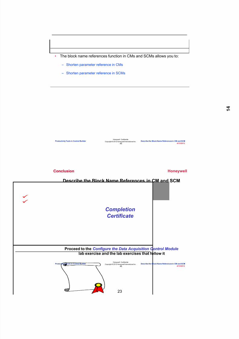
8/9/2019 Student Course Book- Automation
http://slidepdf.com/reader/full/student-course-book-automation 375/1165
23
Honeywell
Honeywell ConfidentialCopyright © 2012 Honeywell International Inc.
4/13/201245
Summary
• The block name references function in CMs and SCMs allows you to:
– Shorten parameter reference in CMs
– Shorten parameter reference in SCMs
Productivity Tools in Control Builder Describe the Block Name References in CM and SCM
Honeywell
Honeywell ConfidentialCopyright © 2012 Honeywell International Inc.
4/13/201246
Describe the Block Name References in CM and SCM
CompletionCertificate
Conclusion
Proceed to the Configure the Data Acquisition Control Modulelab exercise and the lab exercises that follow it
Conclusion
Productivity Tools in Control Builder Describe the Block Name References in CM and SCM

8/9/2019 Student Course Book- Automation
http://slidepdf.com/reader/full/student-course-book-automation 376/1165
Copyright © 201 2 Honeywell International Inc.
HPS Automation College written permission required to distributeHoneywell Confidential and Proprietary
This page was intentionally left blank.

8/9/2019 Student Course Book- Automation
http://slidepdf.com/reader/full/student-course-book-automation 377/1165
4/13/2012 Copyright © 2012 Honeywell International Inc. 1
HPS Automation College written permission required to distributeHoneywell Confidential and Proprietary
Topic: Productivity Tools in Control Builder
Contents
Export/Import a Control Module ............................................................................................................. 3

8/9/2019 Student Course Book- Automation
http://slidepdf.com/reader/full/student-course-book-automation 378/1165
2 Copyright © 2012 Honeywell International Inc. 4/13/2012
HPS Automation College written permission required to distributeHoneywell Confidential and Proprietary
This page was intentionally left blank.

8/9/2019 Student Course Book- Automation
http://slidepdf.com/reader/full/student-course-book-automation 379/1165
Productivity Tools in Control Builder
Export/Import a Control Module
4/13/2012 Copyright © 2012 Honeywell International Inc. 3
HPS Automation College written permission required to distributeHoneywell Confidential and Proprietary
Export/Import a Control Module
Practice
Objective
• Use the Import and Export functionality of Control Builder to incorporate parts from oneControl Builder Project into another Project
• Export the Control Module 11_TI20
• Import Analog Indicator points
• Use Bulk Edit Parameters to change parameter values
Prerequisites
• Experion PKS Server or client machine loaded with Experion PKS Engineering Tools• 11_TI20 CM configured in Control Builder
• Exported files of the Analog Indicator CMs for SIM C200E available in the path:C:\Users\Public\Public Documents\Honeywell\Experion PKS\IXPORT\Student_DB\Series_A
• Exported files of the Analog Indicator CMs for SIM C300 available in the path:C:\ Users\Public\Public Documents\Honeywell\Experion PKS\IXPORT\Student_DB\Series_C
•
Control Builder running with at least one Project/Monitor tree window open• SIM_C200E/SIMC300 Controller and IOMs configured
Introduction
A Project file can contain many items, such as IOMs and CMs, for up to 20 controllers. FromControl Builder, use the Import/Export tool to copy some or all of one project to another.
• Export - copies the designated portion of a project from Control Builder to a specifieddirectory
•
Import - copies the designated CMs into Control Builder’s Project Tab

8/9/2019 Student Course Book- Automation
http://slidepdf.com/reader/full/student-course-book-automation 380/1165
Productivity Tools in Control Builder
Export/Import a Control Module
4 Copyright © 2012 Honeywell International Inc. 4/13/2012
HPS Automation College written permission required to distributeHoneywell Confidential and Proprietary
Procedure
Export Function Block Configuration
Step Action1 In Control Builder, click on the Project window then from the menu bar select File >
Export, to call up the dialog box, as shown below.• Select 11_TI20
ATTENTION
Your point list may be different. The point list containsall items in the current project.

8/9/2019 Student Course Book- Automation
http://slidepdf.com/reader/full/student-course-book-automation 381/1165
Productivity Tools in Control Builder
Export/Import a Control Module
4/13/2012 Copyright © 2012 Honeywell International Inc. 5
HPS Automation College written permission required to distributeHoneywell Confidential and Proprietary
Step Action
2 11_TI20 now appears in the Point Name field.
Browse to the path of:
C:\Users\Public\Public Documents\Honeywell\Experion PKS\Ixport\Export• Double-click Export and click OK

8/9/2019 Student Course Book- Automation
http://slidepdf.com/reader/full/student-course-book-automation 382/1165
Productivity Tools in Control Builder
Export/Import a Control Module
6 Copyright © 2012 Honeywell International Inc. 4/13/2012
HPS Automation College written permission required to distributeHoneywell Confidential and Proprietary
Step Action
3 Click the Export Button.• The Exporting Data dialog box appears
ATTENTION
This dialog box automatically closes if there were noerrors during the export.
4 Open Windows Explorer and navigate to the exported CM location:• C:\ Users\Public\Public Documents\Honeywell\Experion PKS\Ixport\Export • The following files are generated:
Module Name .bcd (In this case, module name is 11_TI20.)
Module Name .cnf.xml
Export.sl
global.gui
global.snl.xml
• The Export.sl is the successful list file. It contains a list of all the exportedobjects
ATTENTION
Here, 11_TI20 was successfully exported. You canimport this CM to any other Project with the Importfacility.

8/9/2019 Student Course Book- Automation
http://slidepdf.com/reader/full/student-course-book-automation 383/1165
Productivity Tools in Control Builder
Export/Import a Control Module
4/13/2012 Copyright © 2012 Honeywell International Inc. 7
HPS Automation College written permission required to distributeHoneywell Confidential and Proprietary
Import a Control Module
Import copies designated Control Modules from the Import/Export files located in the specifieddirectory (shown in the Import form) to a Control Builder Project.
In this lab, import the Analog Indicator points. These are pre-built CMs and already exported intothe following directory:
• Exported files of the Analog Indicator CMs for SIM C200E available in the path:C:\ Users\Public\Public Documents\Honeywell\Experion PKS\Ixport\Student_DB\Series_A
• Exported files of the Analog Indicator CMs for SIM C300 available in the path:C:\ Users\Public\Public Documents\Honeywell\Experion PKS\Ixport\Student_DB\Series_C

8/9/2019 Student Course Book- Automation
http://slidepdf.com/reader/full/student-course-book-automation 384/1165
Productivity Tools in Control Builder
Export/Import a Control Module
8 Copyright © 2012 Honeywell International Inc. 4/13/2012
HPS Automation College written permission required to distributeHoneywell Confidential and Proprietary
Step Action
1 From Control Builder, select File>Import to call up the dialog box, as shown below.
ATTENTION
When the above dialog box opens, the Project Treewindow automatically closes.
All items incurrentImport/
Export TextFiles
Import /Export Text
FilesLocation
Start Import
Selection tools
List of itemsto importbased on
selectionsfrom window
When
enabled,select yourown list of
items toimport
Selection List

8/9/2019 Student Course Book- Automation
http://slidepdf.com/reader/full/student-course-book-automation 385/1165
Productivity Tools in Control Builder
Export/Import a Control Module
4/13/2012 Copyright © 2012 Honeywell International Inc. 9
HPS Automation College written permission required to distributeHoneywell Confidential and Proprietary
Step Action
2 Click the Browse button and change the Import path to the following folder:
C:\ Users\Public\Public Documents\Honeywell\Experion PKS\IXPORT\Student_DB\Series_A (or _C)
TIP
Make sure “Series_A” (or _C) is in the ‘Look in’ fieldbefore clicking OK.
Click OK .

8/9/2019 Student Course Book- Automation
http://slidepdf.com/reader/full/student-course-book-automation 386/1165
Productivity Tools in Control Builder
Export/Import a Control Module
10 Copyright © 2012 Honeywell International Inc. 4/13/2012
HPS Automation College written permission required to distributeHoneywell Confidential and Proprietary
Step Action
3 Import the Analog Indicator points listed below.
Selection can be made with <SHIFT> select (for contiguous items) or <CTRL> select (fornoncontiguous items).
ATTENTION
Select only the following, from the list, to import:
11_PI14, 11_TI21, 11_TI22, 11_TI23, 11_TI24, 11_TI25, 11_TI26 and 11_TI40 .
4 Maintain the Import CEE Assignments checkbox selection. This checkbox imports andassigns the above CMs to the CEESCEFB61 (or SIM_CEEC300).
• If this option is NOT selected, then the imported items are imported asUnassigned

8/9/2019 Student Course Book- Automation
http://slidepdf.com/reader/full/student-course-book-automation 387/1165
Productivity Tools in Control Builder
Export/Import a Control Module
4/13/2012 Copyright © 2012 Honeywell International Inc. 11
HPS Automation College written permission required to distributeHoneywell Confidential and Proprietary
Step Action
5 Click the Import button.• The following dialog box appears:
ATTENTION
This dialog box automatically closes after a successfulImport.
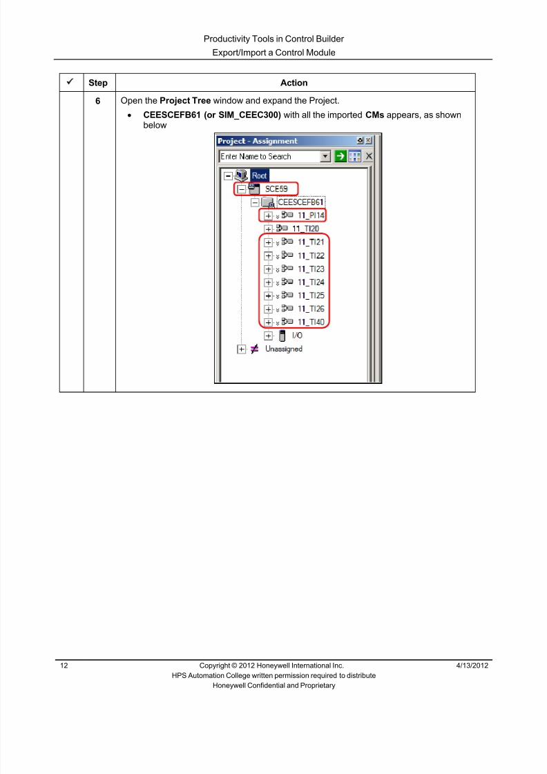
8/9/2019 Student Course Book- Automation
http://slidepdf.com/reader/full/student-course-book-automation 388/1165
Productivity Tools in Control Builder
Export/Import a Control Module
12 Copyright © 2012 Honeywell International Inc. 4/13/2012
HPS Automation College written permission required to distributeHoneywell Confidential and Proprietary
Step Action
6 Open the Project Tree window and expand the Project.• CEESCEFB61 (or SIM_CEEC300) with all the imported CMs appears, as shown
below

8/9/2019 Student Course Book- Automation
http://slidepdf.com/reader/full/student-course-book-automation 389/1165
Productivity Tools in Control Builder
Export/Import a Control Module
4/13/2012 Copyright © 2012 Honeywell International Inc. 13
HPS Automation College written permission required to distributeHoneywell Confidential and Proprietary
Use Bulk Edit Parameters
Step Action
1 Open the Bulk Editor.• Click Tools > Bulk Edit Parameters > Create Bulk Edit List

8/9/2019 Student Course Book- Automation
http://slidepdf.com/reader/full/student-course-book-automation 390/1165

8/9/2019 Student Course Book- Automation
http://slidepdf.com/reader/full/student-course-book-automation 391/1165
Productivity Tools in Control Builder
Export/Import a Control Module
4/13/2012 Copyright © 2012 Honeywell International Inc. 15
HPS Automation College written permission required to distributeHoneywell Confidential and Proprietary
Step Action
3 Select 11_TI21.DACA from the Available Points window then• Click the arrow button• 11_TI21.DACA now appears in the Selected Points window
Similarly, select 11_TI22.DACA, 11_TI23.DACA, 11_TI24.DACA and 11_TI26.DACA and move them to the Selected Points window
ATTENTION
Press <CNTRL> key for selecting multiple points.

8/9/2019 Student Course Book- Automation
http://slidepdf.com/reader/full/student-course-book-automation 392/1165
Productivity Tools in Control Builder
Export/Import a Control Module
16 Copyright © 2012 Honeywell International Inc. 4/13/2012
HPS Automation College written permission required to distributeHoneywell Confidential and Proprietary
Step Action
4 In the Available Parameters window, find and select PVEUHI and PVEXHILM. Selectthe arrow button.
ATTENTION
Press <CNTRL> key for selecting multiple parameters.
5 For C300 students only (C200E students skip this step):
From ‘Available Points’, select and move the following to ‘Selected Points’:
11_TI21.TI, 11_TI22.TI, 11_TI23.TI, 11_TI24.TI, 11_TI26.TI
6 For C300 students only (C200E students skip this step):From ‘Available Parameters’ select and move the following to ‘Selected Parameters’:
PVEXEUHI

8/9/2019 Student Course Book- Automation
http://slidepdf.com/reader/full/student-course-book-automation 393/1165
Productivity Tools in Control Builder
Export/Import a Control Module
4/13/2012 Copyright © 2012 Honeywell International Inc. 17
HPS Automation College written permission required to distributeHoneywell Confidential and Proprietary
Step Action
7 Click the Browse button for the Output Directory .• Select C:\Users\Student in the ‘Browse for Folder’ window• Click OK
8 Select Excel Spread Sheet [.xls] from the Select File Type pull down menu.
Click the Save button.
ATTENTION
If the file already exists in the folder, a prompt will appearasking you to overwrite the existing file. Press YES.

8/9/2019 Student Course Book- Automation
http://slidepdf.com/reader/full/student-course-book-automation 394/1165
Productivity Tools in Control Builder
Export/Import a Control Module
18 Copyright © 2012 Honeywell International Inc. 4/13/2012
HPS Automation College written permission required to distributeHoneywell Confidential and Proprietary
Step Action
9 Click OK .
10 Close the ‘Create Bulk Edit List’ window.

8/9/2019 Student Course Book- Automation
http://slidepdf.com/reader/full/student-course-book-automation 395/1165
Productivity Tools in Control Builder
Export/Import a Control Module
4/13/2012 Copyright © 2012 Honeywell International Inc. 19
HPS Automation College written permission required to distributeHoneywell Confidential and Proprietary
Step Action
11 Open Windows Explorer and navigate to C:\Users\Student • Double click the BulkEdit.xls file• Result: Excel opens displaying the points as shown below
Screen capture shown for SIMC300. You will see this only when using SIMC300

8/9/2019 Student Course Book- Automation
http://slidepdf.com/reader/full/student-course-book-automation 396/1165
Productivity Tools in Control Builder
Export/Import a Control Module
20 Copyright © 2012 Honeywell International Inc. 4/13/2012
HPS Automation College written permission required to distributeHoneywell Confidential and Proprietary
Step Action
12 In the PVEUHI column, select each 100 value and change it to ‘260
In the PVEXHILM, select each 100 value and change it to ‘260 .
ATTENTION
Be sure to put the single quote “ ‘ “ before 260. Thistells Excel that this value is text.
For C300 students only:Enter the PVEXEUHI as 260 for each Series C AnalogInput channel.
Screen capture shown for SIMC300. You will see this only when using SIMC300.

8/9/2019 Student Course Book- Automation
http://slidepdf.com/reader/full/student-course-book-automation 397/1165
Productivity Tools in Control Builder
Export/Import a Control Module
4/13/2012 Copyright © 2012 Honeywell International Inc. 21
HPS Automation College written permission required to distributeHoneywell Confidential and Proprietary
Step Action
13 Save and close the Excel spreadsheet.
Accept the default “C:\Student” file location.

8/9/2019 Student Course Book- Automation
http://slidepdf.com/reader/full/student-course-book-automation 398/1165
Productivity Tools in Control Builder
Export/Import a Control Module
22 Copyright © 2012 Honeywell International Inc. 4/13/2012
HPS Automation College written permission required to distributeHoneywell Confidential and Proprietary
Step Action
14 In Control Builder, select Tools > Bulk Edit Parameters > Read Bulk Edit List .
• Result: the Read Bulk Edit List tool opens

8/9/2019 Student Course Book- Automation
http://slidepdf.com/reader/full/student-course-book-automation 399/1165
Productivity Tools in Control Builder
Export/Import a Control Module
4/13/2012 Copyright © 2012 Honeywell International Inc. 23
HPS Automation College written permission required to distributeHoneywell Confidential and Proprietary
Step Action
15 Click the Browse button.
From the “ C:\Users\Student” , select the BulkEdit.xls file.
Click the Open button.
16 Select the Update Project option.
Click the Start button.

8/9/2019 Student Course Book- Automation
http://slidepdf.com/reader/full/student-course-book-automation 400/1165
Productivity Tools in Control Builder
Export/Import a Control Module
24 Copyright © 2012 Honeywell International Inc. 4/13/2012
HPS Automation College written permission required to distributeHoneywell Confidential and Proprietary
Step Action
17 Click the OK button to acknowledge the warning.
18 Close the Bulk Edit tool.
19 In Control Builder, verify that PVEUHI changed (to 260) for the five points above(11_TI21, 11_TI22, 11_TI23, 11_TI24, 11_TI26).
ATTENTION
If necessary, open the Project Tree, and expand theProject.

8/9/2019 Student Course Book- Automation
http://slidepdf.com/reader/full/student-course-book-automation 401/1165
Productivity Tools in Control Builder
Export/Import a Control Module
4/13/2012 Copyright © 2012 Honeywell International Inc. 25
HPS Automation College written permission required to distributeHoneywell Confidential and Proprietary
Step Action
20 Select the 11_PI14, 11_TI21, 11_TI22, 11_TI23, 11_TI24, 11_TI25, 11_TI26, and11_TI40 points.
Click the Download button.
Click Continue on the Load dialog window.
Select the checkbox with Automatically change… in the Load dialog box, and click OK
to begin the download. After a successful download, go to the Monitoring Tree window, expand your SCE/CEEand verify that the CMs are activated (green).
ATTENTION
Your Project screen may appear slightly different thanthe example above.

8/9/2019 Student Course Book- Automation
http://slidepdf.com/reader/full/student-course-book-automation 402/1165
Productivity Tools in Control Builder
Export/Import a Control Module
26 Copyright © 2012 Honeywell International Inc. 4/13/2012
HPS Automation College written permission required to distributeHoneywell Confidential and Proprietary
Step Action
21 In Station, open the Debutanizer_123 graphic and verify that the downloaded points aredisplaying values. If Debutanizer_123 is already displayed, refresh the display.
• 11_TI40, 11_TI21, and 11_TI23 are shown below

8/9/2019 Student Course Book- Automation
http://slidepdf.com/reader/full/student-course-book-automation 403/1165
Productivity Tools in Control Builder
Export/Import a Control Module
4/13/2012 Copyright © 2012 Honeywell International Inc. 27
HPS Automation College written permission required to distributeHoneywell Confidential and Proprietary
Step Action
22 • 11_TI25, 11_TI24 and 11_TI21 are shown below
• 11_TI22 is shown below
ATTENTION
Your displays may differ.If values for 11_TI20 are not updating, close and re-
open Tie_back_new.xls and verify the following isselected:Tools >Microsoft Excel Data Exchange >Recalculate Every 5 seconds
This file is used for simulation purposes.

8/9/2019 Student Course Book- Automation
http://slidepdf.com/reader/full/student-course-book-automation 404/1165
Productivity Tools in Control Builder
Export/Import a Control Module
28 Copyright © 2012 Honeywell International Inc. 4/13/2012
HPS Automation College written permission required to distributeHoneywell Confidential and Proprietary

8/9/2019 Student Course Book- Automation
http://slidepdf.com/reader/full/student-course-book-automation 405/1165
1
1
Honeywell ConfidentialCopyright © 2012 Honeywell International Inc.
4/13/2012
Describe ERDB Administration
ERDB Administr ation and Other Tools Describe ERDB Administra tionERDB Administr ation and Other Tools Describe ERDB Administra tion
Honeywell
Honeywell ConfidentialCopyright © 2012 Honeywell International Inc.
4/13/20122
Introduction
• In this lesson you will learn about the engineering repository database(ERDB) and how to administer it.
• At the conclusion of this lesson, you will be able to:
– Identify the purpose and location of the ERDB
– Open the Database Administration (DBAdmin) tool for the ERDB
– Describe the DBAdmin functions for the ERDB
ERDB Administr ation and Other Tools Describe ERDB Administra tion

8/9/2019 Student Course Book- Automation
http://slidepdf.com/reader/full/student-course-book-automation 406/1165
2
Honeywell
Honeywell ConfidentialCopyright © 2012 Honeywell International Inc.
4/13/20123
Topics
• Introduction to the ERDB
• Opening and Navigating the DBAdmin Tool for the ERDB
ERDB Administr ation and Other Tools Describe ERDB Administra tion
Honeywell
Honeywell ConfidentialCopyright © 2012 Honeywell International Inc.
4/13/20124
ERDB Description
• The ERDB: – Contains logic CMs/SCMs
from the C200 and C300controllers
– Is created and referencedvia Control Builder andDBAdmin tasks
– Is a purely SQL serverdatabase
ERDB Administr ation and Other Tools Describe ERDB Administra tion

8/9/2019 Student Course Book- Automation
http://slidepdf.com/reader/full/student-course-book-automation 407/1165
3
Honeywell
Honeywell ConfidentialCopyright © 2012 Honeywell International Inc.
4/13/20125
ERDB Location
Program Files > Honeywell > Experion PKS > Engineering Tools > system > ER
ERDB Administr ation and Other Tools Describe ERDB Administra tion
Honeywell
Honeywell ConfidentialCopyright © 2012 Honeywell International Inc.
4/13/20126
ERDB Files
Warning!!!Even though the database fileshave an .mdf extension, they are notMicrosoft Access database files.
Attempting to open these files with anyprogram may corrupt the entire database.
ERDB database file
QVCS database
ERDB Administr ation and Other Tools Describe ERDB Administra tion

8/9/2019 Student Course Book- Automation
http://slidepdf.com/reader/full/student-course-book-automation 408/1165
4
Honeywell
Honeywell ConfidentialCopyright © 2012 Honeywell International Inc.
4/13/20127
Redundant ERDB Servers
Replication Status:No-SyncSyncSync-failSynching
ERDB_A - Secondary
ERDB_B - Primary
ERDB Administr ation and Other Tools Describe ERDB Administra tion
Honeywell
Honeywell ConfidentialCopyright © 2012 Honeywell International Inc.
4/13/20128
Question 1: The ERDB
Incorrect. The false statement is "Its .mdf files can be
opened with any database program ."Attempting to openthe .mdf files may corrupt the entire database.
Click anywhere to continue.
Incorrect. The false statement is "Its .mdf files can be
opened with any database program ."Attempting to openthe .mdf files may corrupt the entire database.
Click anywhere to continue.
Incorrect. The false statement is "Its .mdf files can be
opened with any database program ."Attempting to openthe .mdf files may corrupt the entire database.
Click anywhere to continue.
Correct! The false statement is "Its .mdf files can be
opened with any database program ."Attempting to openthe .mdf files may corrupt the entire database.
Click anywhere to continue.
Correct - Click anywhere to continueIncorrect - Click anywhere to continueYou answered this correctly!
Your answer: The correct answer is:
You did not answer this question completelyYou must answer the question beforecontinuing
Submit Clear
Which statement about the engineering repository database (ERDB) isfalse?
A) It can be redundant
B) It contains logic CMs/SCMsfrom C200 controllers
C) It is created through Control Builder
D) Its .mdf files can be opened withany database program
ERDB Administr ation and Other Tools Describe ERDB Administra tion

8/9/2019 Student Course Book- Automation
http://slidepdf.com/reader/full/student-course-book-automation 409/1165
5
Honeywell
Honeywell ConfidentialCopyright © 2012 Honeywell International Inc.
4/13/20129
Topics
• Introduction to the ERDB
• Opening and Navigating the DBAdmin Tool for the ERDB
ERDB Administr ation and Other Tools Describe ERDB Administra tion
Honeywell
Honeywell ConfidentialCopyright © 2012 Honeywell International Inc.
4/13/201210
Opening DBAdmin for the ERDB
• DBAdmin (ERDB) is opened through Configuration Studio
ERDB Administr ation and Other Tools Describe ERDB Administra tion

8/9/2019 Student Course Book- Automation
http://slidepdf.com/reader/full/student-course-book-automation 410/1165
6
Honeywell
Honeywell ConfidentialCopyright © 2012 Honeywell International Inc.
4/13/201211
DBAdmin Window Panes
Tree pane View pane
ERDB Administr ation and Other Tools Describe ERDB Administra tion
Honeywell
Honeywell ConfidentialCopyright © 2012 Honeywell International Inc.
4/13/201212
DBAdmin Functions for the ERDB
The result is ninedifferent choices for thecontent of the view pane
Click the PLUS sign ( + ) to expandDbAdmin and Experion Node
ERDB Administr ation and Other Tools Describe ERDB Administra tion

8/9/2019 Student Course Book- Automation
http://slidepdf.com/reader/full/student-course-book-automation 411/1165
7
Honeywell
Honeywell ConfidentialCopyright © 2012 Honeywell International Inc.
4/13/201213
DBAdmin Functions for the ERDB
• ERDB Host Information
– General information about the server appears in the view pane
– Use the Tools menu to refresh status
ERDB Administr ation and Other Tools Describe ERDB Administra tion
Honeywell
Honeywell ConfidentialCopyright © 2012 Honeywell International Inc.
4/13/201214
DBAdmin Functions for the ERDB
• A lock dialog box will appear when you attempt to open a locked CM inControl Builder after an abnormal application termination.
ERDB Administr ation and Other Tools Describe ERDB Administra tion

8/9/2019 Student Course Book- Automation
http://slidepdf.com/reader/full/student-course-book-automation 412/1165
8
Honeywell
Honeywell ConfidentialCopyright © 2012 Honeywell International Inc.
4/13/201215
DBAdmin Functions for the ERDB
• ERDB Active Locks allows you to open a locked CM
– CMs in Control Builder that are locked appear in the view pane
– Use the Tools menu to clear all locks
DBAdmin Functions for the ERDB
ERDB Administr ation and Other Tools Describe ERDB Administra tion
Honeywell
Honeywell ConfidentialCopyright © 2012 Honeywell International Inc.
4/13/201216
DBAdmin Functions for the ERDB
• CAB Active Locks also allows you to open a locked CM
ERDB Administr ation and Other Tools Describe ERDB Administra tion

8/9/2019 Student Course Book- Automation
http://slidepdf.com/reader/full/student-course-book-automation 413/1165
9
Honeywell
Honeywell ConfidentialCopyright © 2012 Honeywell International Inc.
4/13/201217
DBAdmin Functions for the ERDB
• ERDB Admin Tasks displays the ERDB administration tasks
ERDB Administr ation and Other Tools Describe ERDB Administra tion
Honeywell
Honeywell ConfidentialCopyright © 2012 Honeywell International Inc.
4/13/201218
ERDB Admin Tasks for Redundant Servers
• The following tasks are only available for redundant servers
ERDB Administr ation and Other Tools Describe ERDB Administra tion

8/9/2019 Student Course Book- Automation
http://slidepdf.com/reader/full/student-course-book-automation 414/1165
10
Honeywell
Honeywell ConfidentialCopyright © 2012 Honeywell International Inc.
4/13/201219
DBAdmin Functions for the ERDB
• Version control system (VCS) Admin Tasks
Synchronize VCS - Synchronizes the Qualification and Version Control Systemdatabase with the Engineering Repository database and clears any QVCS locks.
Backup VCS Database - Creates a backup copy of the current QVCS database as a".bak" file under the user-specified name and in the user-selected directory location.
Restore VCS Database - Restores the user-selected backup QVCS database(.bak) in the primary ERDB through the Restore From dialog box.
ERDB Administr ation and Other Tools Describe ERDB Administra tion
Honeywell
Honeywell ConfidentialCopyright © 2012 Honeywell International Inc.
4/13/201220
DBAdmin Wireless specific Functions
• Wireless Key Server and HART Parameter DB Admin tasks
ERDB Administr ation and Other Tools Describe ERDB Administra tion

8/9/2019 Student Course Book- Automation
http://slidepdf.com/reader/full/student-course-book-automation 415/1165
11
Honeywell
Honeywell ConfidentialCopyright © 2012 Honeywell International Inc.
4/13/201221
Question 2: DBAdmin Tool
Incorrect. The DBAdmin tool is a utilityfor maintaining the ERDB. The ERDBAdministrative tasks are carried out
using the DBAdmin tool.
Click anywhere to continue.
Incorrect. The DBAdmin tool is a utilityfor maintaining the ERDB. The ERDBAdministrative tasks are carried out
using the DBAdmin tool.
Click anywhere to continue.
Correct! The DBAdmin tool is a utility formaintaining the ERDB. The ERDB
Administrative tasks are carried outusing the DBAdmin tool.
Click anywhere to continue.
Incorrect. The DBAdmin tool is a utility formaintaining the ERDB. The ERDB Administrative
tasks are carried out using the DBAdmin tool.
Click anywhere to continue.
Correct - Click anywhere to continueIncorrect - Click anywhere to continueYou answered this correctly!
Your answer:The correct answer is:
You did not answer this question completelyYou must answer the question before
continuing
Submit Clear
The DBAdmin tool is:
A) Used for organizing excelspreadsheets
B) A tool used by operators asa search engine
C) A utility for maintaining theERDB
D) Use to modify tuning parameterson PID control loops
ERDB Administr ation and Other Tools Describe ERDB Administra tion
Honeywell
Honeywell ConfidentialCopyright © 2012 Honeywell International Inc.
4/13/201222
Summary
• The engineering repository database (ERDB):
– Contains control strategies for the C200, C200E and C300 controllers
– Is created through Control Builder
– Is located at Program Files>Honeywell>Experion PKS>EngineeringTools>system>ER
– Is administered through DBAdmin, a Configuration Studio utility
ERDB Administr ation and Other Tools Describe ERDB Administra tion

8/9/2019 Student Course Book- Automation
http://slidepdf.com/reader/full/student-course-book-automation 416/1165
12
Honeywell
Honeywell ConfidentialCopyright © 2012 Honeywell International Inc.
4/13/201223
Conclusion
Describe ERDB Administration
CompletionCertificate
Proceed to the next lesson in your course material.
ERDB Administr ation and Other Tools Describe ERDB Administra tion
Honeywell
Honeywell ConfidentialCopyright © 2012 Honeywell International Inc.
4/13/201224
This page intentionally left blank
ERDB Administr ation and Other Tools Describe ERDB Administra tion

8/9/2019 Student Course Book- Automation
http://slidepdf.com/reader/full/student-course-book-automation 417/1165
1
1
Honeywell ConfidentialCopyright © 2012 Honeywell International Inc.
4/13/2012
Describe Checkpoint Settings in ControlBuilder
Checkpoints Describe Checkpoint Settings in Control BuilderCheckpoints Describe Checkpoint Settings in Control Builder
Honeywell
Honeywell ConfidentialCopyright © 2012 Honeywell International Inc.
4/13/20122
Introduction
• In this lesson you will learn the purpose and use of the checkpointfunction in Control Builder.
• At the conclusion of this lesson,you will know how to:
– Locate the checkpoint file
– Save a checkpoint fileautomatically or manually
– Restore a checkpoint file
Checkpoints Describe Checkpoint Settings in Control Builder

8/9/2019 Student Course Book- Automation
http://slidepdf.com/reader/full/student-course-book-automation 418/1165
2
Honeywell
Honeywell ConfidentialCopyright © 2012 Honeywell International Inc.
4/13/20123
Introduction
• The Checkpoint Function: – Allows you to save and restore operational and configuration data
associated with a control strategy
– C200/C200E, C300, ACE, series CI/O & PM I/O (when used with C300)
– LIOM
– OPC gateway on ACE
– Helps minimize downtime caused by a process or hardware anomaly
Checkpoints Describe Checkpoint Settings in Control Builder
Honeywell
Honeywell ConfidentialCopyright © 2012 Honeywell International Inc.
4/13/20124
Topics
• Locating the Checkpoint File
• Saving Checkpoint Files
• Restoring Checkpoint Files
• Checkpoint Support
Checkpoints Describe Checkpoint Settings in Control Builder

8/9/2019 Student Course Book- Automation
http://slidepdf.com/reader/full/student-course-book-automation 419/1165
3
Honeywell
Honeywell ConfidentialCopyright © 2012 Honeywell International Inc.
4/13/20125
Checkpoint File Location
• The checkpoint file is created on the local server path
• Folders are created for each node – In Checkpoint and in CheckpointBase
• Folders under Checkpoint contain the actualcheckpoint files – Latest (most recent) checkpoint is stored directly
in the node folder (ex: SIM_C300)
– Manual checkpoints are stored in the foldernamed Manual
– User created tasks (manual or auto) savecheckpoints in folders whose name is the same
as the name of the task (ex: CheckpointAll)• Folders under CheckpointBase contain
configuration information, and file managementinformation
Checkpoints Describe Checkpoint Settings in Control Builder
Honeywell
Honeywell ConfidentialCopyright © 2012 Honeywell International Inc.
4/13/20126
Separate foldersfor the controllers
Checkpoint Base Folder
Attribute and Snapshotfile which contains the
configuration information,and file management
information
Checkpoints Describe Checkpoint Settings in Control Builder

8/9/2019 Student Course Book- Automation
http://slidepdf.com/reader/full/student-course-book-automation 420/1165
4
Honeywell
Honeywell ConfidentialCopyright © 2012 Honeywell International Inc.
4/13/20127
Checkpoint Folder
• Each .cp (checkpoint) file contains all files of the CheckpointBase folderin a compressed format supplemented with the saved real-time data forthat instance.
• Sub directories are created for Automatic and Manual scheduled taskcheckpointing and Manual Save operation.
Contains the checkpointfiles which are saved
manually
Latest checkpoint file ofthe Controller named
SCE59 using the SyntaxControllerName_Latest.cp
Contain the checkpointfiles which are saved by
user created tasks – Automatic or Manual
Checkpoints Describe Checkpoint Settings in Control Builder
Honeywell
Honeywell ConfidentialCopyright © 2012 Honeywell International Inc.
4/13/20128
Question 1: Checkpoint File Location
No. The correct answer isC:\Documents and Settings\All Users\ApplicationData\Honeywell\Experion PKS\Checkpoint
Click anywhere to continue
No. The correct answer isC:\Documents and Settings\All Users\Application
Data\Honeywell\Experion PKS\Checkpoint
Click anywhere to continue
No. The correct answer isC:\Documents and Settings\All Users\ApplicationData\Honeywell\Experion PKS\Checkpoint
Click anywhere to continue
Yes! The correct answer isC:\Documents and Settings\All Users\Application
Data\Honeywell\Experion PKS\Checkpoint
Click anywhere to continue
Correct - Click anywhere to continueIncorrect - Click anywhere to continueYou answered this correctly!
Your answer:The correct answer is:
You did not answer this question completelyYou must answer the question beforecontinuing
Submit Clear
Where is the Checkpoint File stored? A) C:\Documents and Settings\AllUsers\ApplicationData\Honeywell\Checkpoint
B) C:\ProgramData\Honeywell\ExperionPKS
C) C:\ProgramData\Honeywell\ExperionPKS\Data
D) C:\ProgramData\Honeywell\ExperionPKS\Checkpoint\Att
Checkpoints Describe Checkpoint Settings in Control Builder

8/9/2019 Student Course Book- Automation
http://slidepdf.com/reader/full/student-course-book-automation 421/1165
5
Honeywell
Honeywell ConfidentialCopyright © 2012 Honeywell International Inc.
4/13/20129
TopicsTopics
• Locating the Checkpoint File
• Saving Checkpoint Files
• Restoring Checkpoint Files
• Checkpoint Support
Checkpoints Describe Checkpoint Settings in Control Builder
Honeywell
Honeywell ConfidentialCopyright © 2012 Honeywell International Inc.
4/13/201210
Automatic Checkpointing
Controller > Checkpoint > Schedule Checkpoint Task
Select to schedule checkpoint
Checkpoints Describe Checkpoint Settings in Control Builder

8/9/2019 Student Course Book- Automation
http://slidepdf.com/reader/full/student-course-book-automation 422/1165
6
Honeywell
Honeywell ConfidentialCopyright © 2012 Honeywell International Inc.
4/13/201211
Checkpoint Task – Manual
Name of the task
Select Controller(s)
Assign Controller(s)
Select Manual
Click
Add commentsif desired
Checkpoints Describe Checkpoint Settings in Control Builder
Honeywell
Honeywell ConfidentialCopyright © 2012 Honeywell International Inc.
4/13/201212
Checkpoint Task – Automatic – Schedule
Select automatic
Select interval
Select the dateand time for thefirst checkpoint
Checkpoints Describe Checkpoint Settings in Control Builder

8/9/2019 Student Course Book- Automation
http://slidepdf.com/reader/full/student-course-book-automation 423/1165
7
Honeywell
Honeywell ConfidentialCopyright © 2012 Honeywell International Inc.
4/13/201213
Automatic Checkpointing
NOTE: The number of versions is grayedout in this case because the QVCS optionwas included with this system.QVCS permits only one version to be retained.
Add number of version tobe retained
Click
Add comment
Checkpoints Describe Checkpoint Settings in Control Builder
Honeywell
Honeywell ConfidentialCopyright © 2012 Honeywell International Inc.
4/13/201214
Automatic Checkpointing
• Checkpoint Scheduler
Start Stop
Define Task
Edit Task Delete Task
Refresh Contents
Checkpoints Describe Checkpoint Settings in Control Builder
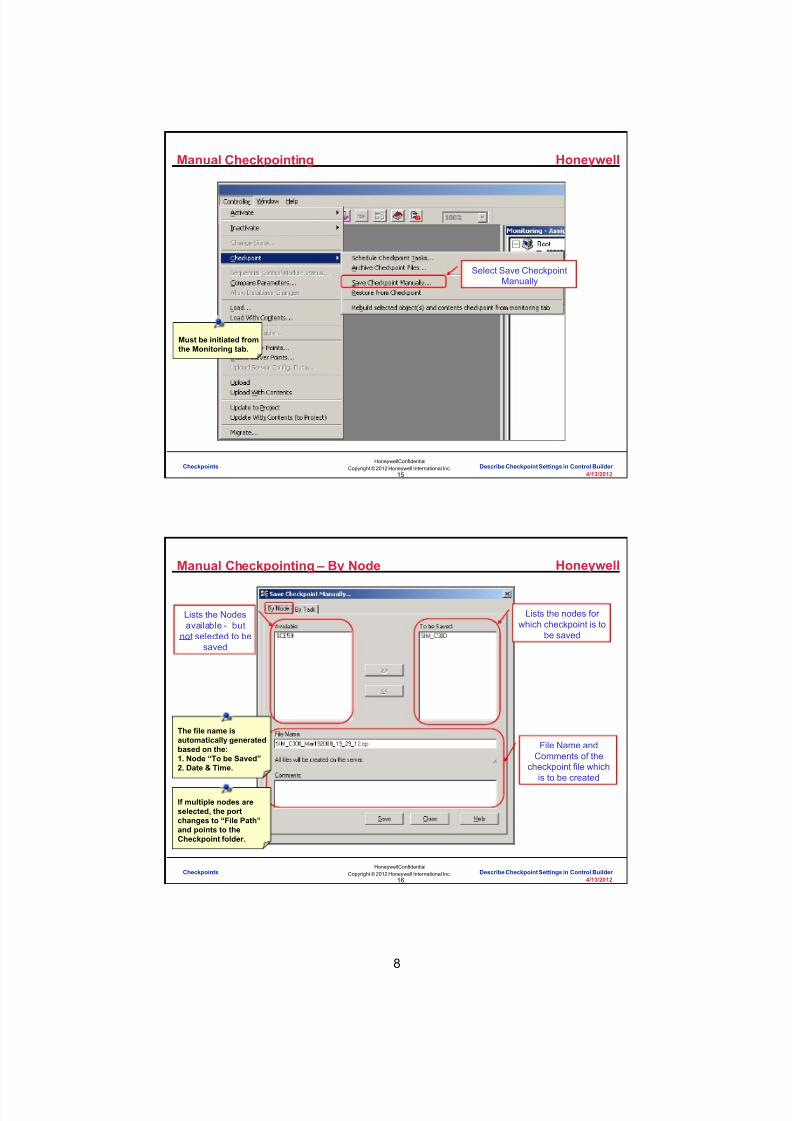
8/9/2019 Student Course Book- Automation
http://slidepdf.com/reader/full/student-course-book-automation 424/1165
8
Honeywell
Honeywell ConfidentialCopyright © 2012 Honeywell International Inc.
4/13/201215
Manual Checkpointing
Select Save CheckpointManually
Must be initiated fromthe Monitoring tab.
Checkpoints Describe Checkpoint Settings in Control Builder
Honeywell
Honeywell ConfidentialCopyright © 2012 Honeywell International Inc.
4/13/201216
Manual Checkpointing – By Node
Lists the nodes forwhich checkpoint is to
be saved
File Name andComments of the
checkpoint file whichis to be created
The file name isautomatically generatedbased on the:1. Node “To be Saved”2. Date & Time.
If multiple nodes areselected, the portchanges to “File Path”and points to theCheckpoint folder.
Lists the Nodesavailable - but
not selected to besaved
Checkpoints Describe Checkpoint Settings in Control Builder

8/9/2019 Student Course Book- Automation
http://slidepdf.com/reader/full/student-course-book-automation 425/1165
9
Honeywell
Honeywell ConfidentialCopyright © 2012 Honeywell International Inc.
4/13/201217
Manual Checkpointing – By Task
File Name (or Path)and Comments of thecheckpoint file which
is to be created
Lists all CheckpointScheduler tasks which
have type=Manual
Lists the nodes to besaved as defined bythe selected task (or
first task listed if noneare selected – as here)
Comments enteredwhen the task was
defined
Checkpoints Describe Checkpoint Settings in Control Builder
Honeywell
Honeywell ConfidentialCopyright © 2012 Honeywell International Inc.
4/13/201218
Question 2: Saving a Checkpoint File
No. The false statement is"You can save a checkpoint file manually
for only one project node."
Click anywhere to continue.
No. The false statement is"You can save a checkpoint file manually
for only one project node."
Click anywhere to continue.
Correct! The false statement is"You can save a checkpoint file manually
for only one project node."
Click anywhere to continue.
No. The false statement is"You can save a checkpoint file manually
for only one project node."
Click anywhere to continue.
Correct - Click anywhere to continueIncorrect - Click anywhere to continueYou answered this correctly!Your answer:The correct answer is:You did not answer this question completelyYou must answer the question before
continuing
Submit Clear
Which statement about saving a checkpoint file is false ? A) If your system has the QVCS option, you will only
be able to save 1 version of the checkpoint fileautomatically; otherwise, you can specify thenumber of versions to save
B) The checkpoint scheduler shows a list of theautomatic and manual checkpoints that have beensaved
C) You can save a checkpoint file manually for only oneproject node
D) When you save a checkpoint file automatically youmust specify the start date, start time and interval
Checkpoints Describe Checkpoint Settings in Control Builder

8/9/2019 Student Course Book- Automation
http://slidepdf.com/reader/full/student-course-book-automation 426/1165
10
Honeywell
Honeywell ConfidentialCopyright © 2012 Honeywell International Inc.
4/13/201219
Topics
• Locating the Checkpoint File
• Saving Checkpoint Files
• Restoring Checkpoint Files
• Checkpoint Support
Checkpoints Describe Checkpoint Settings in Control Builder
Honeywell
Honeywell ConfidentialCopyright © 2012 Honeywell International Inc.
4/13/201220
Restore from Checkpoint
Displays a list of ALL nodesand shows which node(s) are
selected for restore
Location where thecheckpoint file for the
node is saved
List of files availablefor restore
Used to select theRestore scope (onlyavailable for C300)
Checkpoints Describe Checkpoint Settings in Control Builder

8/9/2019 Student Course Book- Automation
http://slidepdf.com/reader/full/student-course-book-automation 427/1165
11
Honeywell
Honeywell ConfidentialCopyright © 2012 Honeywell International Inc.
4/13/201221
Files to Restore
Unavailable for selection
Available for selection
Multiple parent
Nodes selected
Hardware children in
Multiple parent
Hardware children in
Single parent
Single Parent
Node selected
Checkpoints Describe Checkpoint Settings in Control Builder
Honeywell
Honeywell ConfidentialCopyright © 2012 Honeywell International Inc.
4/13/201222
Topics
• Locating the Checkpoint File
• Saving Checkpoint Files
• Restoring Checkpoint Files
• Checkpoint Support
Checkpoints Describe Checkpoint Settings in Control Builder

8/9/2019 Student Course Book- Automation
http://slidepdf.com/reader/full/student-course-book-automation 428/1165
12
Honeywell
Honeywell ConfidentialCopyright © 2012 Honeywell International Inc.
4/13/201223
Checkpoint support for C300, Series C I/O, & PM I/O
• C300 target and save granularity
– C300 CEE with Series A modules supported on C300
– Series C I/O
– PMIO supported on C300
Checkpoints Describe Checkpoint Settings in Control Builder
Honeywell
Honeywell ConfidentialCopyright © 2012 Honeywell International Inc.
4/13/201224
C300 Restore
• Restore from single “C300 Checkpoint file”
C300 selected for restorewith “Restore SelectedNode & its associated
hardware” option selected
Checkpoints Describe Checkpoint Settings in Control Builder

8/9/2019 Student Course Book- Automation
http://slidepdf.com/reader/full/student-course-book-automation 429/1165
13
Honeywell
Honeywell ConfidentialCopyright © 2012 Honeywell International Inc.
4/13/201225
C300 and Series A IO Modules Restore
C300 selected for restorewith “Restore selectedNode” option selected
Checkpoints Describe Checkpoint Settings in Control Builder
Honeywell
Honeywell ConfidentialCopyright © 2012 Honeywell International Inc.
4/13/201226
Series C IO and PM IO Restore
One or more SeriesC IOMsand/or one or more PM
IOPs selected for restore
One IOM or IOP selected
More than one IOM or IOP selected
Checkpoints Describe Checkpoint Settings in Control Builder

8/9/2019 Student Course Book- Automation
http://slidepdf.com/reader/full/student-course-book-automation 430/1165
14
Honeywell
Honeywell ConfidentialCopyright © 2012 Honeywell International Inc.
4/13/201227
C200 and Series A IO Modules Restore
Series A I/O
PM IO
C200_latest.cp or previously savedcompatible file
C200
• C200 Save – Series A I/O – PM IO
C200 selected forrestore. Restore scopeoption is not available
for selection
Checkpoints Describe Checkpoint Settings in Control Builder
Honeywell
Honeywell ConfidentialCopyright © 2012 Honeywell International Inc.
4/13/201228
LIOM Checkpoint Support
• LIOM Controller – Redundant or Non-Redundant configuration – LIOM Block, the LIOM CEE, 621 IOMs, and its contained CMs
LIOM
621 IOM 621 IOM
621 IOM 621 IOM
Latest.cp
Save / restore
During restore, theRestore scope optionwill not be available for
selection
Checkpoints Describe Checkpoint Settings in Control Builder

8/9/2019 Student Course Book- Automation
http://slidepdf.com/reader/full/student-course-book-automation 431/1165
15
Honeywell
Honeywell ConfidentialCopyright © 2012 Honeywell International Inc.
4/13/201229
OPC Gateway Checkpoint Support
• The OPC Gateway is a CPM-like Function Block that resides on an ACENode and provides configuration parameters necessary for OPCconnections from ACE CEEs.
• If the ACE Node that hosts the OPC gateway should fail, the OPCGateway Checkpoint file can be used to restore these configurationparameters.
OPC Gateway latest cp
ACE Restore
OPC gateway
Checkpoints Describe Checkpoint Settings in Control Builder
Honeywell
Honeywell ConfidentialCopyright © 2012 Honeywell International Inc.
4/13/201230
Question 3: Checkpoint Functions
No. All of the above statements are t rueabout Checkpoints.
Click anywhere to continue.
No. All of the above statements are t rueabout Checkpoints.
Click anywhere to continue.
No. All of the above statements are t rueabout Checkpoints.
Click anywhere to continue.
No. All of the above statements are t rueabout Checkpoints.
Click anywhere to continue.
Yes! All of the above statements are trueabout Checkpoints.
Click anywhere to continue.
Correct - Click anywhere to continueIncorrect - Click anywhere to continueYou answered this correctly!
Your answer:The correct answer is:
You did not answer this question completelyYou must answer the question beforecontinuing
Submit Clear
Which of the following statements are true about Checkpoints?
A) C300 checkpoints are stored in a single file
B) PM and Series C IOM can be restored individually,when connected to C300
C) C200 checkpoints if used, restores the C200 and allIOMs
D) Series A I/O connected to C300 cannot be restoredindividually
E) All of the above
Checkpoints Describe Checkpoint Settings in Control Builder

8/9/2019 Student Course Book- Automation
http://slidepdf.com/reader/full/student-course-book-automation 432/1165
16
Honeywell
Honeywell ConfidentialCopyright © 2012 Honeywell International Inc.
4/13/201231
Detail Display
• The System Status Display supports direct navigation to the detaildisplay for a selected node – Checkpoint save and restore operations from the checkpoint TAB in the
detail display
Checkpoints Describe Checkpoint Settings in Control Builder
Honeywell
Honeywell ConfidentialCopyright © 2012 Honeywell International Inc.
4/13/201232
Save Failed Status
• Checkpoint save failed status – Alarm is generated for Checkpoint save failed (System Status Display)
Checkpoints Describe Checkpoint Settings in Control Builder

8/9/2019 Student Course Book- Automation
http://slidepdf.com/reader/full/student-course-book-automation 433/1165
17
Honeywell
Honeywell ConfidentialCopyright © 2012 Honeywell International Inc.
4/13/201233
Checkpoint File Needs the ERDB
• A checkpoint file works together with the ERDB to restore data – The checkpoint file by itself cannot be used to restore data
• A checkpoint file (.CP) can only be restored when EXACTLY the sameversion of the ERDB exists on the server as when the checkpoint wastaken – Example:
• Time 1: A new CM is downloaded (and a checkpoint is taken)• Time 2: A manual checkpoint is taken• Time 3: An automatic checkpoint is taken• Time 4: A CM is modified and downloaded (and a checkpoint is taken)
– Only the checkpoint made at Time 4 is available to restore this controller
• Checkpoint files and the ERDB should be backed up together
Checkpoints Describe Checkpoint Settings in Control Builder
Honeywell
Honeywell ConfidentialCopyright © 2012 Honeywell International Inc.
4/13/201234
Downloading Causes a Checkpoint Status of Incomplete
• When downloading modules (CMs, SCMs, etc.), a checkpoint is taken – Controller data is not uploaded for the modules being downloaded – Checkpoint ‘Entirety’ = Incomplete
• Shown in ‘Restore from Checkpoint’ dialog – Checkpoint Status = “ “
• Shown on the detail display of the controller (checkpoint operations tab)
• Details of the ‘Incomplete’ state show which modules are incomplete – Display the ‘Restore from Checkpoint’ dialog – Select the checkpoint whose ‘Entirety’ = Incomplete – Click the ‘Details’ button
• If this CP is used to restore, only configuration checkpoint data (CCD)will be restored for modules which have an incomplete status – Operational checkpoint data (OCD) will not be restored
• Performing a separate checkpoint after the download will create a“complete” checkpoint
Checkpoints Describe Checkpoint Settings in Control Builder

8/9/2019 Student Course Book- Automation
http://slidepdf.com/reader/full/student-course-book-automation 434/1165
18
Honeywell
Honeywell ConfidentialCopyright © 2012 Honeywell International Inc.
4/13/201235
Summary
• The Checkpoint function in Control Builder:
– Saves and restores operational and configuration data
– Speeds recovery from process or hardware anomalies
– Can be done manually or automatically at set intervals
Checkpoints Describe Checkpoint Settings in Control Builder
Honeywell
Honeywell ConfidentialCopyright © 2012 Honeywell International Inc.
4/13/201236
Conclusion
Describe Checkpoint Settings in Control Builder
CompletionCertificate
Proceed to the Open and Operate Control Builder lab exercise.
Checkpoints Describe Checkpoint Settings in Control Builder

8/9/2019 Student Course Book- Automation
http://slidepdf.com/reader/full/student-course-book-automation 435/1165
4/13/2012 Copyright © 2012 Honeywell International Inc. 1
HPS Automation College written permission required to distributeHoneywell Confidential and Proprietary
Topic: Checkpoints
Contents
Perform Checkpoint Save ...................................................................................................................... 3
Perform Checkpoint Restore ................................................................................................................. 7

8/9/2019 Student Course Book- Automation
http://slidepdf.com/reader/full/student-course-book-automation 436/1165
2 Copyright © 2012 Honeywell International Inc. 4/13/2012
HPS Automation College written permission required to distributeHoneywell Confidential and Proprietary
This page was intentionally left blank.

8/9/2019 Student Course Book- Automation
http://slidepdf.com/reader/full/student-course-book-automation 437/1165
Checkpoints
Perform Checkpoint Save
4/13/2012 Copyright © 2012 Honeywell International Inc. 3
HPS Automation College written permission required to distributeHoneywell Confidential and Proprietary
Perform Checkpoint Save
Practice
Introduction
In this lab, you will learn the Checkpoint save operation
Prerequisites
• SIM_C300 / SCE59 must be configured and loaded

8/9/2019 Student Course Book- Automation
http://slidepdf.com/reader/full/student-course-book-automation 438/1165
Checkpoints
Perform Checkpoint Save
4 Copyright © 2012 Honeywell International Inc. 4/13/2012
HPS Automation College written permission required to distributeHoneywell Confidential and Proprietary
Step Action
Save Checkpoint Manually
1 On the Monitoring tab, right-click on the controller (SCE59 or SIM_C300) and selectCheckpoint > Save Checkpoint manually…

8/9/2019 Student Course Book- Automation
http://slidepdf.com/reader/full/student-course-book-automation 439/1165
Checkpoints
Perform Checkpoint Save
4/13/2012 Copyright © 2012 Honeywell International Inc. 5
HPS Automation College written permission required to distributeHoneywell Confidential and Proprietary
Step Action
2 Click Save to save the checkpoint file.
3 On the Save Checkpoint message window click OK .

8/9/2019 Student Course Book- Automation
http://slidepdf.com/reader/full/student-course-book-automation 440/1165
Checkpoints
Perform Checkpoint Save
6 Copyright © 2012 Honeywell International Inc. 4/13/2012
HPS Automation College written permission required to distributeHoneywell Confidential and Proprietary
Step Action
4 On the Save Checkpoint Manually window click Close .
ATTENTION
The status of the checkpoint save can be confirmedfrom the Event Summary page in Station as shownbelow

8/9/2019 Student Course Book- Automation
http://slidepdf.com/reader/full/student-course-book-automation 441/1165
Checkpoints
Perform Checkpoint Restore
4/13/2012 Copyright © 2012 Honeywell International Inc. 7
HPS Automation College written permission required to distributeHoneywell Confidential and Proprietary
Perform Checkpoint Restore
Practice
Introduction
In this lab, you will learn the Checkpoint Restore operation
• Checkpoint restore from Control Builder
• Checkpoint restore from Station
Prerequisites
• SIM_C300 / SCE59 must be configured and loaded
Note:
1. On completion of this lab, the SIM_C300 / C200E, and the associated I/O and strategies will be restored.

8/9/2019 Student Course Book- Automation
http://slidepdf.com/reader/full/student-course-book-automation 442/1165
Checkpoints
Perform Checkpoint Restore
8 Copyright © 2012 Honeywell International Inc. 4/13/2012
HPS Automation College written permission required to distributeHoneywell Confidential and Proprietary
Step Action
Restore From Checkpoint
1 To change the status of the controller to ‘Fail’, open the Services window and restart theExperion CDA-SP service .
ATTENTION
To open Services window, click Start Run and typeServices.msc and click OK
To restart the Experion CDA-SP service, right click onthe service and select Restart
2 Open Control Builder, if not already open. The status of SIM_C300 / SCE59 haschanged to idle and the CEE and I/O status changed to fail.

8/9/2019 Student Course Book- Automation
http://slidepdf.com/reader/full/student-course-book-automation 443/1165
Checkpoints
Perform Checkpoint Restore
4/13/2012 Copyright © 2012 Honeywell International Inc. 9
HPS Automation College written permission required to distributeHoneywell Confidential and Proprietary
Step Action
3 Right-click on SIM_C300 / SCE59 in Monitoring tab. Select Checkpoint > Restorefrom Checkpoint .
4 Verify that the Latest checkpoint status is ‘Complete’ (in the ‘Entirely’ column).
5 Select the ‘Latest’ Checkpoint file from the list and click Restore.
6 Click Continue in the Restore from Checkpoint message window

8/9/2019 Student Course Book- Automation
http://slidepdf.com/reader/full/student-course-book-automation 444/1165
Checkpoints
Perform Checkpoint Restore
10 Copyright © 2012 Honeywell International Inc. 4/13/2012
HPS Automation College written permission required to distributeHoneywell Confidential and Proprietary
Step Action
7 You should get a message indicating that the ”Restore completed successfully”
8 Close both ‘Restore from Checkpoint’ windows.
9 On to the Monitoring tab, check that the status of the controller and all the other itemsunder it appear in healthy status (green or blue).
10 Change the state of the CEE to WARMSTART.11 Verify that all of the IO modules and Control Modules are active.
Restore Checkpoint From Detail Display
12 Repeat Step 1 to change the status of SIM_C300 / SCE59 to Fail.
13 Open the Station application.
14 Open the Detail Display for SIM_C300 / SCE59.
15 Click Checkpoint Operations tab in the detail display

8/9/2019 Student Course Book- Automation
http://slidepdf.com/reader/full/student-course-book-automation 445/1165
Checkpoints
Perform Checkpoint Restore
4/13/2012 Copyright © 2012 Honeywell International Inc. 11
HPS Automation College written permission required to distributeHoneywell Confidential and Proprietary
Step Action
16 Change the Security Level to ‘mngr’. Click Restore from checkpoint .
17 Repeat earlier steps to restore the checkpoint of SIM_C300 / SCE59

8/9/2019 Student Course Book- Automation
http://slidepdf.com/reader/full/student-course-book-automation 446/1165
Checkpoints
Perform Checkpoint Restore
12 Copyright © 2012 Honeywell International Inc. 4/13/2012
HPS Automation College written permission required to distributeHoneywell Confidential and Proprietary
Step Action
18 Open the detail display of SIM_CEEC300 / CEESCEFB61 and change the state of CEEto WARMSTART

8/9/2019 Student Course Book- Automation
http://slidepdf.com/reader/full/student-course-book-automation 447/1165
Checkpoints
Perform Checkpoint Restore
4/13/2012 Copyright © 2012 Honeywell International Inc. 13
HPS Automation College written permission required to distributeHoneywell Confidential and Proprietary
Step Action
19 Go back to Control Builder Monitoring tab and verify that the status of SIM_C300 /SCE59 controller and its I/O’s are healthy. Activate the I/O modules and Control Modulesif not active.
ATTENTION
Checkpoint Save and Restore for Series C I/O, andPMIO when used with C300, is supported from bothControl Builder and Station point Detail Displays
The screen might look different, if you are using SIM-C300

8/9/2019 Student Course Book- Automation
http://slidepdf.com/reader/full/student-course-book-automation 448/1165
Checkpoints
Perform Checkpoint Restore
14 Copyright © 2012 Honeywell International Inc. 4/13/2012
HPS Automation College written permission required to distributeHoneywell Confidential and Proprietary
This page was intentionally left blank.
8/9/2019 Student Course Book- Automation
http://slidepdf.com/reader/full/student-course-book-automation 449/1165
1
1
Honeywell ConfidentialCopyright © 2012 Honeywell International Inc.
4/13/2012
Describe PV Tracking and InitializationFundamentals
PID Control Module Describe PV Tracking and Initialization FundamentalsPID Control Module Describe PV Tracking and Initialization Fundamentals
Honeywell
Honeywell ConfidentialCopyright © 2012 Honeywell International Inc.
4/13/20122
Overview
• Topics – PV Tracking
– Initialization
– Mode behavior after IOL / IOP communication error
PID Control Module Describe PV Tracking and Initialization Fundamentals

8/9/2019 Student Course Book- Automation
http://slidepdf.com/reader/full/student-course-book-automation 450/1165
2
Honeywell
Honeywell ConfidentialCopyright © 2012 Honeywell International Inc.
4/13/20123
Introduction
• PV Tracking sets the SP equal to the PV when automatic control isdisabled (e.g. cascade is broken or the mode is Manual)
• Setpoint (SP) tracks Process Value (PV) to avoid output bumps whenautomatic control is re-established
• Setpoint Limits are still enforced when automatic control is disabled andPV tracking is enabled – If the PV is greater than SPHI, then the SP will be set equal to SPHI – If the PV is less than SPLO, then the SP will be set equal to SPLO
PID Control Module Describe PV Tracking and Initialization Fundamentals
Honeywell
Honeywell ConfidentialCopyright © 2012 Honeywell International Inc.
4/13/20124
PV Tracking
• The PV tracking option is typically configured for PID blocks in acascade configuration – Allows the PID block to resume control with no error after initialization or
when it is taken out of Manual mode – PV tracking option sets SP equal to PV when the cascade is broken due to
function block initialization, an operator action, or a program action (such assetting the mode to Manual)
• The PV Tracking option is enabled on the SetPoint Tab of a PID block
PV Tracking
PV Tracking whenblock is Initializingand mode is Auto
PID Control Module Describe PV Tracking and Initialization Fundamentals

8/9/2019 Student Course Book- Automation
http://slidepdf.com/reader/full/student-course-book-automation 451/1165
3
Honeywell
Honeywell ConfidentialCopyright © 2012 Honeywell International Inc.
4/13/20125
PV Tracking Options
• If the first PV tracking option is enabled (and PV Tracking in Auto/Init isnot enabled), the function block will set the SP equal to the PV (subjectto SP limits) when the PID loop is set to Manual mode.
• Note 1: PV tracking will not occur on recovery from a bad PV• Note 2: PV tracking will not occur if a block is in the Auto mode. If a PID
is in Auto mode, it means the SP value is normally stored by the user; ifPV tracking was available for Auto mode, the user SP would be lost
– The first PV Tracking option will not work when the block is Initializing andthe mode is Auto
• PV Tracking in Auto Initialize mode
– When checked, PV Track in Auto/Init is enabled and provides PV Trackingwhen the block is in Auto mode and it is undergoing initialization (INITMANis On)
PID Control Module Describe PV Tracking and Initialization Fundamentals
Honeywell
Honeywell ConfidentialCopyright © 2012 Honeywell International Inc.
4/13/20126
PV Tracking
• After enabling the PV Tracking option
SP is equal to PV when mode isin MAN
PID Control Module Describe PV Tracking and Initialization Fundamentals

8/9/2019 Student Course Book- Automation
http://slidepdf.com/reader/full/student-course-book-automation 452/1165
4
Honeywell
Honeywell ConfidentialCopyright © 2012 Honeywell International Inc.
4/13/20127
PV Tracking in Auto/Init
• When the mode is changed from CAS in a secondary controller,INITMAN is turned ON in the primary controller
• If the option Enable PV Tracking in Auto/Init is checked, the SP will trackthe PV if INITMAN is ON, even if the mode of the primary controller is
Auto
Mode is AUTO
Block is inInitialize State
SP tracks PV whenblock is in an Initialize
state and in Auto mode
PID Control Module Describe PV Tracking and Initialization Fundamentals
Honeywell
Honeywell ConfidentialCopyright © 2012 Honeywell International Inc.
4/13/20128
Initialization Propagation
• Initialization propagation – Occurs when control blocks check the downstream blocks for broken loop – In case of a broken loop, each block will initialize itself and provide an
initialization request and initialization value to its primary (upstream) block – Initialization starts at the final control element and propagates upstream
• In a Cascade control loop – Secondary controller block initializes itself and sends an initialization request
to Primary controller when its MODE is changed from CAS – Initialization does not occur when Secondary controller mode is changed
from AUTO/MAN to CAS
• Initialization requests are brought in from downstream blocks using the
implicit BACKCALC connection for each output
• Downstream block may propagate one shot initialization requests to anupstream block – Occurs when a block is activated or returning from bad control
PID Control Module Describe PV Tracking and Initialization Fundamentals

8/9/2019 Student Course Book- Automation
http://slidepdf.com/reader/full/student-course-book-automation 453/1165
5
Honeywell
Honeywell ConfidentialCopyright © 2012 Honeywell International Inc.
4/13/20129
Initialization (Cascade Control Loop)
• When the mode of a secondary controller is changed from CAS,INITMAN is turn ON in the primary controller
• INITMAN parameter indicates the initialization status
Primary Controller Secondary Controller
INITMAN is ONfor PrimaryController
PID Control Module Describe PV Tracking and Initialization Fundamentals
Honeywell
Honeywell ConfidentialCopyright © 2012 Honeywell International Inc.
4/13/201210
Initialization Parameters
• When INITMAN is ON – Function block is in Initialization Manual
– Either a cascade is broken (i.e., secondary controller mode is not Cascade),or initialization is requested by a secondary downstream block
• INITMAN is available in following blocks – All RegCtl blocks, DevCtl, Pulse Count Control, Pulse Length Control,
HTmotor, LTmotor, Solenoid, ValveDamper
• Secondary Initialization Option – When enabled, a Regulatory Control function block ignores initialization
requests from the secondary
– There is one SECINITOPT parameter for each secondary• Number of secondary connection depends on the function block type
PID Control Module Describe PV Tracking and Initialization Fundamentals

8/9/2019 Student Course Book- Automation
http://slidepdf.com/reader/full/student-course-book-automation 454/1165
6
Honeywell
Honeywell ConfidentialCopyright © 2012 Honeywell International Inc.
4/13/201211
Enable Bad Output Connection Option (BADOCOPTENB)
• When communication to the Input Output Processor (IOP) is lost: – Mode is set to MAN – Mode attribute is set to OPERATOR – Initialization (this block & upstream)
• Available in all regulatory control blocks• Applicable for the following I/O:
– PM I/O – Series C I/O – Series A and H (except Fieldbus, Profibus, and DeviceNet on Series A I/O)
• Disabled by default
PID Control Module Describe PV Tracking and Initialization Fundamentals
Honeywell
Honeywell ConfidentialCopyright © 2012 Honeywell International Inc.
4/13/201212
Bad Output Connection Option (BADOCOPT)
• BADOCOPT = NaN – Initialization request (this block & upstream) occurs immediately – No mode shed occurs
• BADOCOPT = 0 sec (same as BADOCOPTENB = Disabled) – Initialization request (this block & upstream) occurs immediately – Mode & ModeAttr = MAN & OPERATOR immediately – User must restore mode after the communication with the I/O is restored
• BADOCOPT = 1 to 60 sec – Initialization request (this block & upstream) occurs immediately – Mode & ModeAttr = MAN & OPERATOR after BADOCOPT seconds
• Or during the next CM execution after BADOCOPT seconds – Communication restored within BADOCOPT seconds:
• Normal operation is automatically restored without user intervention
– Communication NOT restored within BADOCOPT seconds:• User must restore mode after the communication with the I/O is restored
Bad Output Connection Option:Nan, 0, 1-60
PID Control Module Describe PV Tracking and Initialization Fundamentals

8/9/2019 Student Course Book- Automation
http://slidepdf.com/reader/full/student-course-book-automation 455/1165
7
Honeywell
Honeywell ConfidentialCopyright © 2012 Honeywell International Inc.
4/13/201213
Bad Output Connection Option (BADOCOPT) Diagrams• BADOCOPT
= NaN
• BADOCOPT= 0 sec (sameas BADOCOPTENB= Disabled)
• BADOCOPT
= 1 to 60 sec
Lose communication to IOP
Init RequestNo Mode Shed
Lose communication to IOP
Init RequestMode Shed
Lose communication to IOP
Init Request
BADOCOPT Seconds
Communication restored Communication restored
Communication restored
User must restore mode
Normal operation restored automatically
Mode shed
User must restore mode
Time
Time
Time
Communication restored
Normal operation restored automatically
PID Control Module Describe PV Tracking and Initialization Fundamentals
Honeywell
Honeywell ConfidentialCopyright © 2012 Honeywell International Inc.
4/13/201214
RegCtl Block Detail Display
• Bad Output Connection Options (BADOCOPT) is available on Main tabof detail display
PID Control Module Describe PV Tracking and Initialization Fundamentals

8/9/2019 Student Course Book- Automation
http://slidepdf.com/reader/full/student-course-book-automation 456/1165
8
Honeywell
Honeywell ConfidentialCopyright © 2012 Honeywell International Inc.
4/13/201215
Uncommanded Mode Change Alarm
• Alarm indicates a mode change due to the ‘Bad Output ConnectionOption’ – Only available when BADOCOPTENB is enabled
• Alarm returns to normal when the user restores (changes to) any mode
PID Control Module Describe PV Tracking and Initialization Fundamentals
Honeywell
Honeywell ConfidentialCopyright © 2012 Honeywell International Inc.
4/13/201216
What Causes an I/O Communication Failure?
• The following result in an I/O communication failure: – Removing the physical card from the rack – Loss of communication on the I/O link – Power cycle of the remote chassis which has an AO or DO card – The diagnostic failure of an individual slot – Failure of the I/O processor – Removing the local or remote CNI card or removing the ControlNet cable or
FTE cable connecting to the IOLIM
• Items which do NOT cause the RegCtl block to shed mode: – Activating or inactivating an IOM function block – Activating or inactivating a CEE that contains an IOM block – Activating or inactivating a CM which has an AO or DO channel associated
with an IOM function block
PID Control Module Describe PV Tracking and Initialization Fundamentals

8/9/2019 Student Course Book- Automation
http://slidepdf.com/reader/full/student-course-book-automation 457/1165
9
Honeywell
Honeywell ConfidentialCopyright © 2012 Honeywell International Inc.
4/13/201217
Summary
• PV Tracking
– PV Tracking (when enabled) locks the SP to the PV -- the SP remains equal to the PV(subject to SP limits) as long as the mode is Manual
– PV Tracking in Auto/Init -- when the mode of a secondary controller is not in CAS, theparameter INITMAN is turned ON in the primary controller. If the option Enable PVTracking in Auto/Init is checked, the SP will track the PV even if the mode of theprimary controller is Auto.
• Initialization – Initialization occurs in a cascade loop when the mode of a secondary controller is not
in CAS, which causes the INITMAN parameter to turn ON in the primary controller. Ina single loop, initialization can be caused by a problem with a secondary downstreamblock. Any block that can be initialized has an associated BACKCALC variable.
– Initialization requests from a point’s secondary or downstream block are brought inthrough the implicit BACKCALC connection for each output.
• Mode Behavior after IOL or IOP communication error – Eliminates user intervention to restore regulatory control block mode, when
communication failure is restored very quickly
– Provides a new parameter option (BADOCOPT) in regulatory control block to allowusers to select the mode behavior – Provides Access Lock to configuration parameters to prevent unauthorized user
access to the functionality
PID Control Module Describe PV Tracking and Initialization Fundamentals
Honeywell
Honeywell ConfidentialCopyright © 2012 Honeywell International Inc.
4/13/201218
Describe PV Tracking and Initialization Fundamentals
CompletionCertificate
Conclusion
Proceed to the Configure a PID Control Module lab exercise andthe lab exercises that follow it
Conclusion
PID Control Module Describe PV Tracking and Initialization Fundamentals

8/9/2019 Student Course Book- Automation
http://slidepdf.com/reader/full/student-course-book-automation 458/1165
Copyright © 201 2 Honeywell International Inc.
HPS Automation College written permission required to distributeHoneywell Confidential and Proprietary
This page was intentionally left blank.

8/9/2019 Student Course Book- Automation
http://slidepdf.com/reader/full/student-course-book-automation 459/1165
4/13/2012 Copyright © 2012 Honeywell International Inc. 1
HPS Automation College written permission required to distributeHoneywell Confidential and Proprietary
Topic: PID Control Module
Contents
Configure a PID Control Module ............................................................................................................ 3
Calculate Performance Statistics of the Configuration Performed (C200 & C300) ............................. 37

8/9/2019 Student Course Book- Automation
http://slidepdf.com/reader/full/student-course-book-automation 460/1165
2 Copyright © 2012 Honeywell International Inc. 4/13/2012
HPS Automation College written permission required to distributeHoneywell Confidential and Proprietary
This page was intentionally left blank.

8/9/2019 Student Course Book- Automation
http://slidepdf.com/reader/full/student-course-book-automation 461/1165
PID Control Module
Configure a PID Control Module
4/13/2012 Copyright © 2012 Honeywell International Inc. 3
HPS Automation College written permission required to distributeHoneywell Confidential and Proprietary
Configure a PID Control Module
Practice
Objective
• Configure a Control Module
• Use the naming conventions for the Control Module and function blocks within the controlmodule.
• Configure a Control Module with a single PID loop
Prerequisites
• Experion PKS Server or Client machine loaded with Experion PKS Engineering Tools
• Debutanizer_123 graphic loaded on the Server (This will be required at a later time to checkthe control strategy.)
• Control Builder running with the Project and Monitoring tree windows open
• SIM-C200E/C200E, or SIM-C300/C300 Controller and IOMs configured
• Excel Data Exchange open and loaded with the simulation spread sheet

8/9/2019 Student Course Book- Automation
http://slidepdf.com/reader/full/student-course-book-automation 462/1165
PID Control Module
Configure a PID Control Module
4 Copyright © 2012 Honeywell International Inc. 4/13/2012
HPS Automation College written permission required to distributeHoneywell Confidential and Proprietary
Introduction
The Heavy Feed Flow FC01 is built in this lab. This PID loop requires bumpless Auto – Manualtransfer with alarms, groups, and historization enabled.
The PID loop will be built, loaded and activated. The remaining Control Modules, of a similar type,are imported into the project.
To create a control strategy, a Control Module 11_FC01 must be built and function blocks insertedand connected. Once the Control Modules are built or imported, you can test them with the
simulation.In this lab, you will build a control module for a simple PID loop 11_FC01 for the heavy feed to thedebutanizer tower T-100.
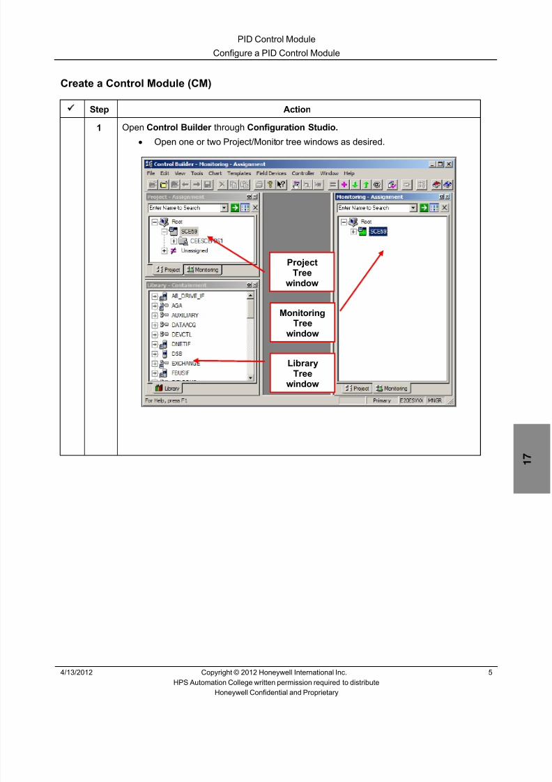
8/9/2019 Student Course Book- Automation
http://slidepdf.com/reader/full/student-course-book-automation 463/1165
PID Control Module
Configure a PID Control Module
4/13/2012 Copyright © 2012 Honeywell International Inc. 5
HPS Automation College written permission required to distributeHoneywell Confidential and Proprietary
Create a Control Module (CM)
Step Action
1 Open Control Builder through Configuration Studio.• Open one or two Project/Monitor tree windows as desired.
Project
Treewindow
LibraryTree
window
MonitoringTree
window

8/9/2019 Student Course Book- Automation
http://slidepdf.com/reader/full/student-course-book-automation 464/1165
PID Control Module
Configure a PID Control Module
6 Copyright © 2012 Honeywell International Inc. 4/13/2012
HPS Automation College written permission required to distributeHoneywell Confidential and Proprietary
Step Action
2 Select File > New > Control Module .
3 Double-click the blank chart background.
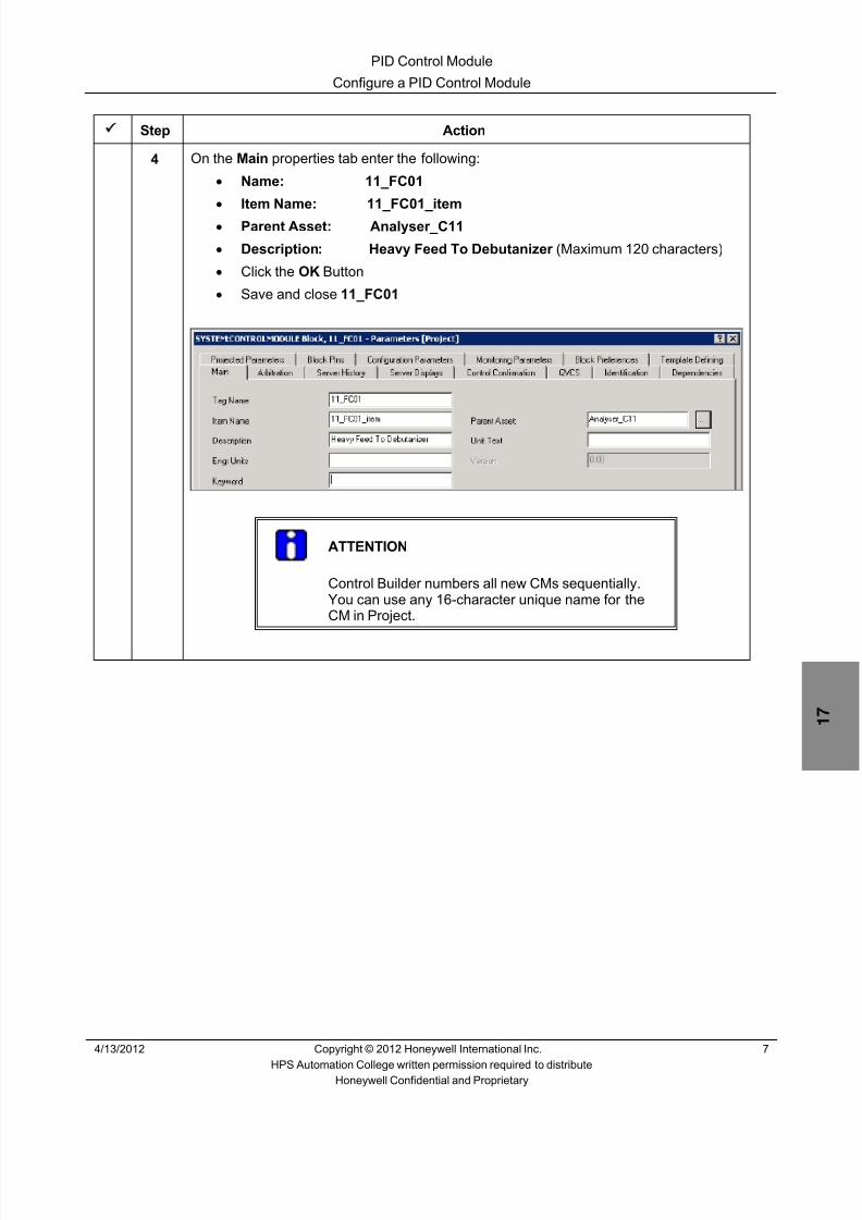
8/9/2019 Student Course Book- Automation
http://slidepdf.com/reader/full/student-course-book-automation 465/1165
PID Control Module
Configure a PID Control Module
4/13/2012 Copyright © 2012 Honeywell International Inc. 7
HPS Automation College written permission required to distributeHoneywell Confidential and Proprietary
Step Action
4 On the Main properties tab enter the following:• Name: 11_FC01 • Item Name: 11_FC01_item • Parent Asset: Analyser_C11 • Description: Heavy Feed To Debutanizer (Maximum 120 characters)• Click the OK Button• Save and close 11_FC01
ATTENTION
Control Builder numbers all new CMs sequentially.You can use any 16-character unique name for theCM in Project.

8/9/2019 Student Course Book- Automation
http://slidepdf.com/reader/full/student-course-book-automation 466/1165
PID Control Module
Configure a PID Control Module
8 Copyright © 2012 Honeywell International Inc. 4/13/2012
HPS Automation College written permission required to distributeHoneywell Confidential and Proprietary
Step Action
5 For this Lab, use the specified CM names, because this allows you to test the CMs withthe pre-configured Excel spreadsheet, used for simulation.
• CM 11_FC01 is added to the Unassigned node in Project window
ATTENTION
Your Project window may differ. Verify that 11_FC01 isin the Unassigned node.
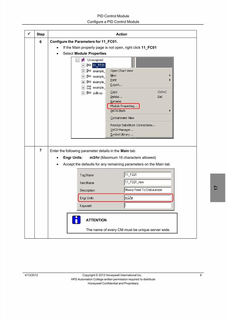
8/9/2019 Student Course Book- Automation
http://slidepdf.com/reader/full/student-course-book-automation 467/1165
PID Control Module
Configure a PID Control Module
4/13/2012 Copyright © 2012 Honeywell International Inc. 9
HPS Automation College written permission required to distributeHoneywell Confidential and Proprietary
Step Action
6 Configure the Parameters for 11_FC01.• If the Main property page is not open, right click 11_FC01 • Select Module Properties
7 Enter the following parameter details in the Main tab.
• Engr Units : m3/hr (Maximum 16 characters allowed)
• Accept the defaults for any remaining parameters on the Main tab
ATTENTION
The name of every CM must be unique server wide.

8/9/2019 Student Course Book- Automation
http://slidepdf.com/reader/full/student-course-book-automation 468/1165
PID Control Module
Configure a PID Control Module
10 Copyright © 2012 Honeywell International Inc. 4/13/2012
HPS Automation College written permission required to distributeHoneywell Confidential and Proprietary
Step Action
8 Click the Server Displays tab.
Enter the following Display details:
Point Detail Display: sysDtlPIDA
Click the OK button.
ATTENTION
The Group detail display for 11_FC01 in Station will bedirectly picked from the type of Point detail displayspecified.
You can directly add a CM, to a Trend and Group byentering trend/group numbers and the pen/position inTrends and Groups windows, here or after building thecontrol strategy in the CM.

8/9/2019 Student Course Book- Automation
http://slidepdf.com/reader/full/student-course-book-automation 469/1165
PID Control Module
Configure a PID Control Module
4/13/2012 Copyright © 2012 Honeywell International Inc. 11
HPS Automation College written permission required to distributeHoneywell Confidential and Proprietary
Step Action
9 Assign the CM to the controller CEESCEFB61 (For SIM C200E) or SIM_CEEC300(For SIM C300)
• With the CM 11_FC01 selected, click the (Assign ) button on the toolbar,
to open the Execution Environment Assignment dialog.• Select 11_FC01 in the CMs/SCMs tab in Available Modules list box• Select CEESCEFB61 or SIM_CEEC300 in the Assign To list box• Click the Assign button• 11_FC01 is added to Assigned Modules list box• Click the Close button
• 11_FC01 is now assigned to CEESCEFB61 or SIM_CEEC300 , as indicated below
For SIM-C200E For SIM C300

8/9/2019 Student Course Book- Automation
http://slidepdf.com/reader/full/student-course-book-automation 470/1165
PID Control Module
Configure a PID Control Module
12 Copyright © 2012 Honeywell International Inc. 4/13/2012
HPS Automation College written permission required to distributeHoneywell Confidential and Proprietary
Add Function Blocks to a CM
After creating a CM, you must design the control strategy by adding relevant Input/Output blocksand control blocks such as PIDs, device control or logic blocks.
The IOMs configured in the Configure C200E Hardware and Series A IOM/Configure C300 Hardware and Series C IOM lab are used here.
Step Action
1 Double-click 11_FC01 in the Project window to open the chart view, and then maximizethe view.
2 Add Function Blocks to the CM• From the Library tab, expand the IOCHANNEL (For Series A I/O) or
Series_C_IO AI-HL (For Series C I/O)• Select AICHANNEL
For Series A I/OFor Series C I/O
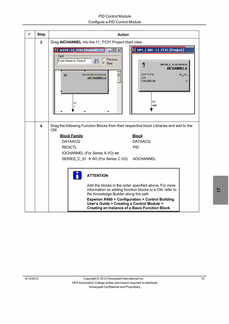
8/9/2019 Student Course Book- Automation
http://slidepdf.com/reader/full/student-course-book-automation 471/1165

8/9/2019 Student Course Book- Automation
http://slidepdf.com/reader/full/student-course-book-automation 472/1165
PID Control Module
Configure a PID Control Module
14 Copyright © 2012 Honeywell International Inc. 4/13/2012
HPS Automation College written permission required to distributeHoneywell Confidential and Proprietary
Step Action
5 After adding all the blocks, arrange them as shown below.
For SIM-C200EFor SIM-C300
6 Configure AIChannel parameters :• Double-click the AICHANNEL block to open the AI parameter configuration
form.• Enter the Channel Name as FI.
For Series A I/O For Series C I/O
TIP (Only for Series C IO Channels)
Channel PV Range parameters can be configured inSeries C AI Channel block
Therefore, PV ranges for Analog Inputs must beconfigured for both the Series C AI Channel block andthe DACA block
7 For C300s ONLY:
Change the ranges of the FI block as follows:
PV Extended High Range 600.9
PV High Range 600
PV Low Range 0
PV Extended Low Range -6.9

8/9/2019 Student Course Book- Automation
http://slidepdf.com/reader/full/student-course-book-automation 473/1165
PID Control Module
Configure a PID Control Module
4/13/2012 Copyright © 2012 Honeywell International Inc. 15
HPS Automation College written permission required to distributeHoneywell Confidential and Proprietary
Step Action
8 Assign the AI Channel to an AI Module.
For C200E:
Step Action
1 Refer to Appendix 1 – C200E I/O list assignments at theend of Appendix for the following information on11_FC01.FI:Module Name:
Channel Number:
2 In the properties of the AI channel (FI block), use the pull-down list to select the module name.
3 Select the channel number.
4 Click the ‘ Assign Channel Block ’ button.
5 Click the OK button to close FI properties.
For C300:
Step Action
1 Refer to Appendix 1 – C300 I/O list assignments at theend of Appendix for the following information on11_FC01.FI:Module Name:
Channel Number:
2 Click the OK button to close FI properties.
3 Right-click the AI channel (FI block) and select FunctionBlock Assign .
4 In the ‘Function Block Assignment Dialog’, select theappropriate channel (use the Module Name (IOM Name),and the Channel Number from above), and click the Assign button.

8/9/2019 Student Course Book- Automation
http://slidepdf.com/reader/full/student-course-book-automation 474/1165
PID Control Module
Configure a PID Control Module
16 Copyright © 2012 Honeywell International Inc. 4/13/2012
HPS Automation College written permission required to distributeHoneywell Confidential and Proprietary
Step Action
9 Configure a Data Acquisition Block. Double-click the Data Acquisition Block, to openthe configuration form, and enter the following:
Name: DACA
Description: Heavy Feed to Debutanizer Engr Units: m3/hr PVEU Range Hi: 600 PVEU Range Lo: 0 PV Extended Hi Limit: 600.9 PV Extended Lo Limit: -6.9 Clamping Option: ENABLE
Accept the defaults for any remaining parameters on this tab.
ATTENTION
You must name this block DACA so that theHoneywell supplied Analog Point Details displayfunctions properly when called from Station

8/9/2019 Student Course Book- Automation
http://slidepdf.com/reader/full/student-course-book-automation 475/1165
PID Control Module
Configure a PID Control Module
4/13/2012 Copyright © 2012 Honeywell International Inc. 17
HPS Automation College written permission required to distributeHoneywell Confidential and Proprietary
Step Action
10 Select the Show Parameter Names checkbox located at the lower left corner. Note thatthe parameter names now appear in place of the parameter descriptions.
ATTENTION
This displays the parameter names instead ofparameter descriptions.
11 Uncheck the Show Parameter Names checkbox.
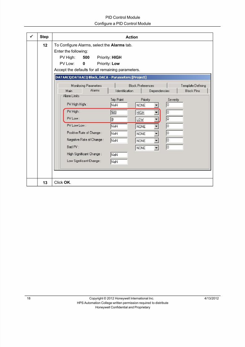
8/9/2019 Student Course Book- Automation
http://slidepdf.com/reader/full/student-course-book-automation 476/1165
PID Control Module
Configure a PID Control Module
18 Copyright © 2012 Honeywell International Inc. 4/13/2012
HPS Automation College written permission required to distributeHoneywell Confidential and Proprietary
Step Action
12 To Configure Alarms, select the Alarms tab.
Enter the following:
PV High: 500 Priority: HIGH
PV Low: 0 Priority: Low
Accept the defaults for all remaining parameters.
13 Click OK .

8/9/2019 Student Course Book- Automation
http://slidepdf.com/reader/full/student-course-book-automation 477/1165
PID Control Module
Configure a PID Control Module
4/13/2012 Copyright © 2012 Honeywell International Inc. 19
HPS Automation College written permission required to distributeHoneywell Confidential and Proprietary
Step Action
14 To Configure a PID Block :
Double click PIDA.
Enter the following:
Name: PIDA Description: Heavy Feed to Debutanizer Engineering Units: m3/hr
PVEU Range Hi: 600 PVEU Range Low: 0 Select the Enable Secondary Initialization Option checkbox.
Normal Mode: AUTO Normal Mode Attribute: OPERATOR
Accept the defaults for all remaining parameters on this tab.
ATTENTION
This block must be named PIDA for the Honeywell suppliedstandard PID Point Detail Display to function properly.

8/9/2019 Student Course Book- Automation
http://slidepdf.com/reader/full/student-course-book-automation 478/1165
PID Control Module
Configure a PID Control Module
20 Copyright © 2012 Honeywell International Inc. 4/13/2012
HPS Automation College written permission required to distributeHoneywell Confidential and Proprietary
Step Action
15 Click the Algorithm tab in the PID configuration form and enter the following
Control Equation type: EQB Integral Time (T1): 0.2 Linear Gain Options: LIN Overall Gain: 0.40
ATTENTION
The Algorithm form allows you to configure PID controlequation types, associated PID equation parametersand gain options for the PID block.
16 Click the SetPoint Tab and enter the following:
High Limit: 600 Low Limit: 0Ensure Enable PV Tracking is selected.

8/9/2019 Student Course Book- Automation
http://slidepdf.com/reader/full/student-course-book-automation 479/1165
PID Control Module
Configure a PID Control Module
4/13/2012 Copyright © 2012 Honeywell International Inc. 21
HPS Automation College written permission required to distributeHoneywell Confidential and Proprietary
Step Action
17 Click the Alarms tab of PID and enter the following:
Type: OP High
Trip Point: 95
Priority: LOW

8/9/2019 Student Course Book- Automation
http://slidepdf.com/reader/full/student-course-book-automation 480/1165
PID Control Module
Configure a PID Control Module
22 Copyright © 2012 Honeywell International Inc. 4/13/2012
HPS Automation College written permission required to distributeHoneywell Confidential and Proprietary
Step Action
18 To add or remove Block Pins in a Functional Block :Click on the Block Pins tab.
In the ‘Selected Parameters’ portion of the window, for the PV parameter, change thelocation to ‘Left’ by:
Click on the “ TOP ” value on the PV parameter Location column.
Select LEFT from the drop down combo box.

8/9/2019 Student Course Book- Automation
http://slidepdf.com/reader/full/student-course-book-automation 481/1165
PID Control Module
Configure a PID Control Module
4/13/2012 Copyright © 2012 Honeywell International Inc. 23
HPS Automation College written permission required to distributeHoneywell Confidential and Proprietary
Step Action
19 As a result of the previous change in pin location, the PV pin shifted to the left side of thePID block faceplate, as indicated below.
Click OK.
20 Configure the AO Block .
Double-click the AOChannelA Block and enter the following:
Channel Name: FV

8/9/2019 Student Course Book- Automation
http://slidepdf.com/reader/full/student-course-book-automation 482/1165
PID Control Module
Configure a PID Control Module
24 Copyright © 2012 Honeywell International Inc. 4/13/2012
HPS Automation College written permission required to distributeHoneywell Confidential and Proprietary
Step Action
21 Assign the AO block to an AO channel.
For C200E:
Step Action
1 Refer to Appendix 1 – C200E I/O list assignments at theend of Appendix for the following information on11_FC01.FV:Module Name:
Channel Number:
2 In the properties of the AO channel (FV block), use the pull-down list to select the module name.
3 Select the channel number.
4 Click the ‘ Assign Channel Block ’ button.
5 Click the OK button to close FV properties.
For C300:
Step Action
1 Refer to Appendix 1 – C300 I/O list assignments at theend of Appendix for the following information on11_FC01.FV:Module Name:
Channel Number:
2 Click the OK button to close FV properties.
3 Right-click the AO channel (FV block) and select FunctionBlock Assign .
4 In the ‘Function Block Assignment Dialog’, select theappropriate channel (use the Module Name (IOM Name),and the Channel Number from above), and click the Assign button.

8/9/2019 Student Course Book- Automation
http://slidepdf.com/reader/full/student-course-book-automation 483/1165
PID Control Module
Configure a PID Control Module
4/13/2012 Copyright © 2012 Honeywell International Inc. 25
HPS Automation College written permission required to distributeHoneywell Confidential and Proprietary
Connect Function Blocks
After adding the Function Blocks, wire them together to form a Control Strategy. You can wireBlocks together anytime you choose, before or after configuring block parameters.
Step Action
1From the Main Menu, Select Chart > Insert > Wire, OR Click the button in thetoolbar.
• The cursor changes to a PLUS (+) sign inside the Project chart window• Click the PV pin displayed in the AICHANNEL ( FI) block and then click the P1 pin
in the DATAACQ ( DACA ) block• These function blocks are now connected

8/9/2019 Student Course Book- Automation
http://slidepdf.com/reader/full/student-course-book-automation 484/1165
PID Control Module
Configure a PID Control Module
26 Copyright © 2012 Honeywell International Inc. 4/13/2012
HPS Automation College written permission required to distributeHoneywell Confidential and Proprietary
Step Action
2 Repeat the above steps to connect PV pin of DATAACQ ( DACA ) to the PV of PIDA.
3 Connect the PIDA OP pin to the OP pin of AO.•
Your CM should be similar to the one shown below.
4 Select File > Save .

8/9/2019 Student Course Book- Automation
http://slidepdf.com/reader/full/student-course-book-automation 485/1165
PID Control Module
Configure a PID Control Module
4/13/2012 Copyright © 2012 Honeywell International Inc. 27
HPS Automation College written permission required to distributeHoneywell Confidential and Proprietary
Step Action
5 Configure History Collection, Trends and Groups .
Double-click in the white space of the chart view of 11_FC01 to open its configurationform. Select the Server History tab.
In the History Configuration section, in the Parameter column, row 1, click the (PointSelection) button to open the Point Selection form.
Select the row having Point name 11_FC01 and Block Name PIDA , as shown in thescreen capture.
Select OP for the Parameter.
Click OK to close the Point selection form.
6 11_FC01.PIDA.OP appears in the History Configuration table.• Click to select the FAST (Fast History) and STD (Standard History) options• 11_FC01.PIDA.OP will now be historized
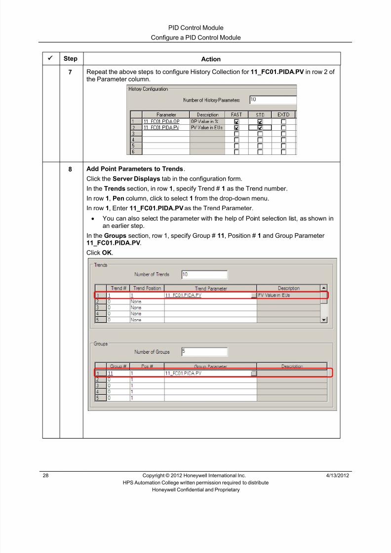
8/9/2019 Student Course Book- Automation
http://slidepdf.com/reader/full/student-course-book-automation 486/1165
PID Control Module
Configure a PID Control Module
28 Copyright © 2012 Honeywell International Inc. 4/13/2012
HPS Automation College written permission required to distributeHoneywell Confidential and Proprietary
Step Action
7 Repeat the above steps to configure History Collection for 11_FC01.PIDA .PV in row 2 ofthe Parameter column.
8 Add Point Parameters to Trends .
Click the Server Displays tab in the configuration form.
In the Trends section, in row 1, specify Trend # 1 as the Trend number.
In row 1, Pen column, click to select 1 from the drop-down menu.
In row 1, Enter 11_FC01.PIDA.PV as the Trend Parameter.• You can also select the parameter with the help of Point selection list, as shown in
an earlier step.
In the Groups section, row 1, specify Group # 11 , Position # 1 and Group Parameter11_FC01.PIDA.PV .
Click OK .
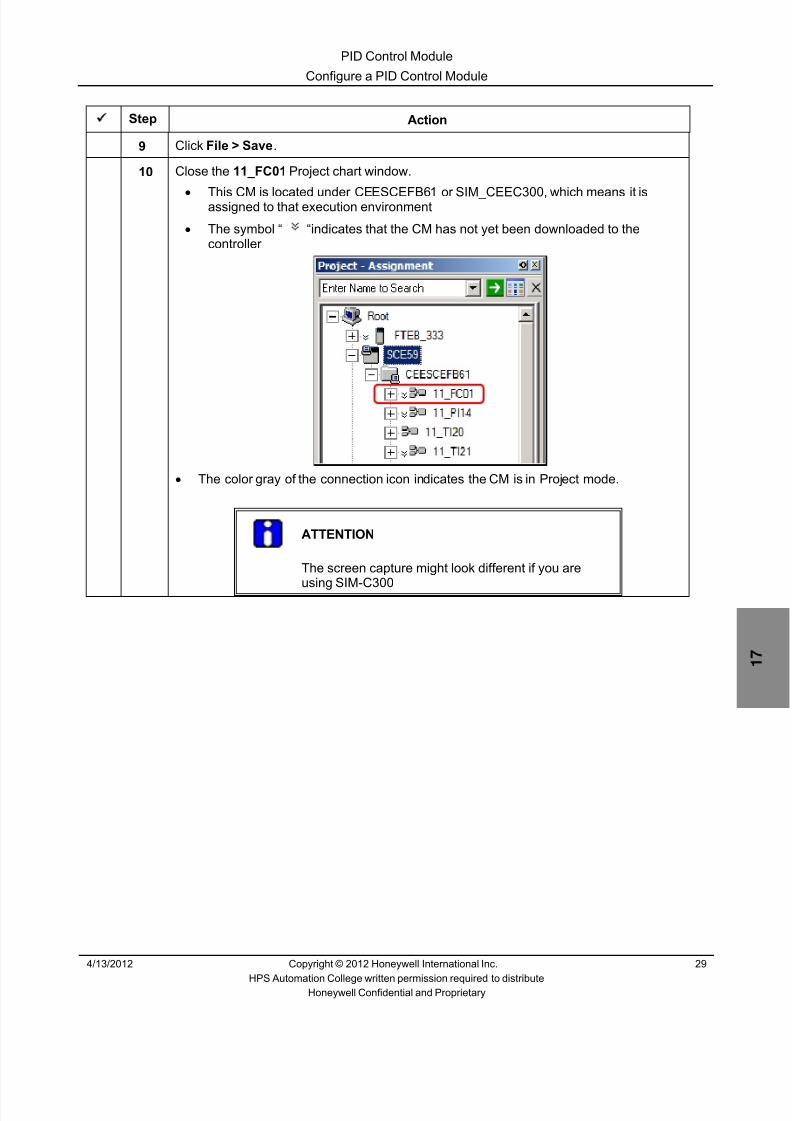
8/9/2019 Student Course Book- Automation
http://slidepdf.com/reader/full/student-course-book-automation 487/1165
PID Control Module
Configure a PID Control Module
4/13/2012 Copyright © 2012 Honeywell International Inc. 29
HPS Automation College written permission required to distributeHoneywell Confidential and Proprietary
Step Action
9 Click File > Save .
10 Close the 11_FC01 Project chart window.•
This CM is located under CEESCEFB61 or SIM_CEEC300, which means it isassigned to that execution environment• The symbol “ “indicates that the CM has not yet been downloaded to the
controller
• The color gray of the connection icon indicates the CM is in Project mode.
ATTENTION
The screen capture might look different if you are
using SIM-C300

8/9/2019 Student Course Book- Automation
http://slidepdf.com/reader/full/student-course-book-automation 488/1165
PID Control Module
Configure a PID Control Module
30 Copyright © 2012 Honeywell International Inc. 4/13/2012
HPS Automation College written permission required to distributeHoneywell Confidential and Proprietary
Step Action
11 Download this CM.• Select 11_FC01
• Click the on the toolbar• Click Continue on the Load window showing the warning• Select the Automatically change… checkbox.
This ensures that the post load state is automatically set as ACTIVE
12 Click OK .• A Load dialog box appears and closes on a successful download
• In Project, notice that there is no “ “ symbol in front of 11_FC01

8/9/2019 Student Course Book- Automation
http://slidepdf.com/reader/full/student-course-book-automation 489/1165
PID Control Module
Configure a PID Control Module
4/13/2012 Copyright © 2012 Honeywell International Inc. 31
HPS Automation College written permission required to distributeHoneywell Confidential and Proprietary
Step Action
13 Click the Monitoring tab to verify that 11_FC01 is active (green).
• If the CM is active (green) skip the next step• If the CM is inactive (blue) perform the next step
ATTENTION
The screen capture might look different if you are using SIM-C300

8/9/2019 Student Course Book- Automation
http://slidepdf.com/reader/full/student-course-book-automation 490/1165
PID Control Module
Configure a PID Control Module
32 Copyright © 2012 Honeywell International Inc. 4/13/2012
HPS Automation College written permission required to distributeHoneywell Confidential and Proprietary
Step Action
14 Activate the CM (right-click 11_FC01 and select “Activate”) or select 11_FC01 and click
the (Toggle State) button from the toolbar, to open the following.
Click Yes .• Notice that the 11_FC01 changes to green indicating it is now active
Monitoring tree status information is indicated by different symbols and colors,as shown below:
CPM/SCE Symbols
1 Grey - As seen in project tree.
1 Grey – Project tree
2 Grey - Loaded not monitored
3 Red - Communication failure
4 Yellow - Not used
5 Green - Active
6 Red - Failed
7 Yellow - Not Loaded
8 Blue – Loaded
1 2 3 4 5 6 7 8

8/9/2019 Student Course Book- Automation
http://slidepdf.com/reader/full/student-course-book-automation 491/1165
PID Control Module
Configure a PID Control Module
4/13/2012 Copyright © 2012 Honeywell International Inc. 33
HPS Automation College written permission required to distributeHoneywell Confidential and Proprietary
Step Action
CEE/ CEESCE Symbols
1 2 3 4 5 6
1 Grey - As seen in project tree
2 Grey - Loaded not monitored
3 Red - Communication failure
4 Blue - Inactive
5 Green - Active
6 Red - Configuration Error
CM Symbols
1 2 3 4 5
1 Grey - As seen in project tree
2 Grey - Loaded not monitored
3 Red - Communication failure
4 Blue - Inactive
5 Green – Active
15 Open Station, access and refresh the Debutanizer_123 graphic.• Change the 11_FC01 controller to AUTO mode• Click the SP value and enter 400 in the 11_FC01 faceplate.
ATTENTION
Open the Tie_Back_New Excel spreadsheet to observe the values for PVand OP.
If the PV value for the point is not updating then restart the Tie_Back_NewExcel spreadsheet. This spreadsheet is used for simulation purposes.

8/9/2019 Student Course Book- Automation
http://slidepdf.com/reader/full/student-course-book-automation 492/1165
PID Control Module
Configure a PID Control Module
34 Copyright © 2012 Honeywell International Inc. 4/13/2012
HPS Automation College written permission required to distributeHoneywell Confidential and Proprietary
Step Action
16 To watch the trend in Station:
Click the button in Station.
Enter 1 in command line. Change the trend interval, if necessary.Zoom the line trend to get a closer display.
17 To see the CM in the Group display:
• Click button on Station.• Type 11 and press the Enter key.

8/9/2019 Student Course Book- Automation
http://slidepdf.com/reader/full/student-course-book-automation 493/1165
PID Control Module
Configure a PID Control Module
4/13/2012 Copyright © 2012 Honeywell International Inc. 35
HPS Automation College written permission required to distributeHoneywell Confidential and Proprietary
Step Action
18 From the Group Display, change the MD to MAN.
Change the OP to 30 .• The PV will change because the OP changed. The SP follows the PV because PV
tracking is enabled• This tests your CM 11_FC01
19 In Control Builder, import (with CEE assignment) 11_FC02 , 11_FC28 and 11_PC15 fromthe following location:
C:\ Users\Public\Public Documents\Honeywell\Experion PKS\Ixport\Student_DB\Series_A (or _C).
ATTENTION
If needed, follow the steps in the Import/Export Lab forimporting the above CMs.
If you are Using SIMC200E/C200E the path for Database
isC:\ Users\Public\Public Documents\Honeywell\Experion PKS\Ixport\Student_DB\Series_A
If you are Using SIMC300/C300, the path for Database isC:\ Users\Public\Public Documents\Honeywell\Experion PKS\Ixport\Student_DB\Series_C
20 From Project, download (with activation) the CMs imported in the previous step.

8/9/2019 Student Course Book- Automation
http://slidepdf.com/reader/full/student-course-book-automation 494/1165
PID Control Module
Configure a PID Control Module
36 Copyright © 2012 Honeywell International Inc. 4/13/2012
HPS Automation College written permission required to distributeHoneywell Confidential and Proprietary
Step Action
21 Verify that the three CMs are active (green) in the Monitoring tab.
22 Open Station and access the Debutanizer_123 graphic.
ATTENTION
Verify that the imported CMs have values. (Ifnecessary, place the imported loops in AUTO modeand provide suitable SP values to see a PV response.)

8/9/2019 Student Course Book- Automation
http://slidepdf.com/reader/full/student-course-book-automation 495/1165
PID Control Module
Calculate Performance Statistics of the Configuration Performed (C200 & C300)
4/13/2012 Copyright © 2012 Honeywell International Inc. 37
HPS Automation College written permission required to distributeHoneywell Confidential and Proprietary
Calculate Performance Statistics of the Configuration Performed (C200& C300)
Practice
Objective
• To calculate the Processing Units and Memory units for given blocks for C200E, and C300.
Prerequisites
• Knowledge of Memory Units and Process Units in C200E, and C300.
Introduction
• This exercise will allow you to determine about Memory Units and Process Units used in
C200E, and C300.

8/9/2019 Student Course Book- Automation
http://slidepdf.com/reader/full/student-course-book-automation 496/1165
PID Control Module
Calculate Performance Statistics of the Configuration Performed (C200 & C300)
38 Copyright © 2012 Honeywell International Inc. 4/13/2012
HPS Automation College written permission required to distributeHoneywell Confidential and Proprietary
Procedure
Control Module Calculation
Step Action1 Calculate MU and PU for C200E, and C300.
2 If CM is build using 1AI, 1DACA, 1PID, and 1AO, 6 Logic FBs, total Memory Unitsconsume is______?
3 If CM is build using 1AI, 1DACA FB, Total Memory Units Consume is ______?
4 Calculate Processing Units (PU) for a typical Regulatory control CM with ExecutionPeriod of .5 Sec _____?
5 Calculate Processing Units (PU) for a typical Analog Data Acquisition CM with ExecutionPeriod of .5 Sec _____?
6 Calculate Processing Units (PU) for 20 Analog Data Acquisition CM with ExecutionPeriod of .1 Sec _____?
7 Calculate Processing Units (PU) for 40 Regulatory control CM with Execution Period of.5 Sec _____?
8 Where do you verify the Memory Units (MU) consumption in C300? _______
9 Calculate Processing Units (PU) for a typical Device control CM with Execution Period of.1 Sec _____?
10 Calculate Processing Units (PU) for 50 Device control CM with Execution Period of .1Sec _____?
11 Calculate Processing Units (PU) for 4 SCM with Execution Period of .1 Sec _____?
12 Calculate Memory Units (MU) for 40 Regulatory control CM _____?
13 Calculate Memory Units (MU) for 5 Auxiliary Function CM _____?
14 Calculate Memory Units (MU) for 10 Analog Data Acquisition CM _____?
15 Calculate Memory Units (MU) for 100 Device control CM _____?
16 Calculate Memory Units (MU) for 10 Logic control CM _____?

8/9/2019 Student Course Book- Automation
http://slidepdf.com/reader/full/student-course-book-automation 497/1165
4/13/2012 Copyright © 2012 Honeywell International Inc. 1
HPS Automation College written permission required to distributeHoneywell Confidential and Proprietary
Topic: PID with Split Range Control Module
Contents
Configure a PID Control Module with Split Range Outputs ................................................................... 3

8/9/2019 Student Course Book- Automation
http://slidepdf.com/reader/full/student-course-book-automation 498/1165
2 Copyright © 2012 Honeywell International Inc. 4/13/2012
HPS Automation College written permission required to distributeHoneywell Confidential and Proprietary
This page was intentionally left blank.

8/9/2019 Student Course Book- Automation
http://slidepdf.com/reader/full/student-course-book-automation 499/1165
PID with Split Range Control Module
Configure a PID Control Module with Split Range Outputs
4/13/2012 Copyright © 2012 Honeywell International Inc. 3
HPS Automation College written permission required to distributeHoneywell Confidential and Proprietary
Configure a PID Control Module with Split Range Outputs
Practice
Objective
• Configure a Split Range Control Module.
• Configure an AUTOMANUAL and FANOUT block.
Prerequisites
• Knowledge of Configuration Studio.
• Experion PKS Server or client machine with Experion PKS Engineering Tools loaded.
• The Debutanizer_123 graphics loaded on the Server. (This will be required at a later time to
check the control strategy.)• Control Builder running with one or two tree windows open.
• SIM-C200E/C200E or SIM-C300/C300 Controller and IOMs configured.
• Excel Data Exchange open with the simulation spread sheet loaded.

8/9/2019 Student Course Book- Automation
http://slidepdf.com/reader/full/student-course-book-automation 500/1165
PID with Split Range Control Module
Configure a PID Control Module with Split Range Outputs
4 Copyright © 2012 Honeywell International Inc. 4/13/2012
HPS Automation College written permission required to distributeHoneywell Confidential and Proprietary
Introduction
A reflux drum D-100 has a split range pressure controller 11_PC16. It controls the pressure on D-100 by split range action on two valves, PV16A and PV16B, where PV16A is reverse acting and
PV16B is direct acting.
The following table illustrates how valves PC16A and PC16B open with the split range signal.Valve PC16A is the valve on the line bypassing the debutanizer overhead condenser E-110. ValvePC16B is on the line connecting D-100 to the compressor interstage drum, which provides a back
pressure of 240 kPag (35 psig). The flare has a backpressure of 14 kPag (2.0 psig).
Signal from 11_PC16 Valve Condition
0 PC16A Fully Open
50 PC16A Closed
50 PC16B Closed
100 PC16B Fully Open
You will first import 11_HC41 (D-100 Overhead to Flare) and 11_HC44 (D-100 Bypass fromCompressor Interstage Drum), which are hand-control valves (Analog Output points).
The 11_PC16 control module is then built, and you can test the logic with simulation.
CM Name Action to be taken
11_HC41 and 11_HC44 Import the CMs from existing database.
11_PC16 Split Range PID ControlModule
Configure PID block, Auto Manual ( AUTOMAN )block and FANOUT block.
Perform the following procedures in Control Builder.

8/9/2019 Student Course Book- Automation
http://slidepdf.com/reader/full/student-course-book-automation 501/1165
PID with Split Range Control Module
Configure a PID Control Module with Split Range Outputs
4/13/2012 Copyright © 2012 Honeywell International Inc. 5
HPS Automation College written permission required to distributeHoneywell Confidential and Proprietary
Procedure
Configure Split Range Control Loop
Step Action1 Import valves.
From Project, Import (with CEE assignment) the hand control valves 11_HC41 and11_HC44 from the following location:
C:\ Users\Public\Public Documents \Honeywell\Experion PKS\IXPORT\Student_DB\Series_A (or _C)
ATTENTION
If needed, follow the steps in the Import/Export Lab forimporting the above CMs.

8/9/2019 Student Course Book- Automation
http://slidepdf.com/reader/full/student-course-book-automation 502/1165
PID with Split Range Control Module
Configure a PID Control Module with Split Range Outputs
6 Copyright © 2012 Honeywell International Inc. 4/13/2012
HPS Automation College written permission required to distributeHoneywell Confidential and Proprietary
Step Action
2 Build a new CM.
Drag a Control Module from the Library tab to the CEE in the Project window.
3 In the Name New Function Block(s) window, enter:
Destination Tag Name: 11_PC16 Destination Item Name: 11_PC16_item
Click FinishThis adds 11_PC16 in the assigned tree in the Project Tree window.
Drag here

8/9/2019 Student Course Book- Automation
http://slidepdf.com/reader/full/student-course-book-automation 503/1165
PID with Split Range Control Module
Configure a PID Control Module with Split Range Outputs
4/13/2012 Copyright © 2012 Honeywell International Inc. 7
HPS Automation College written permission required to distributeHoneywell Confidential and Proprietary
Step Action
4 Expand the tree and double-click 11_PC16 to open the chart view.
Double-click the white space to open the Parameter Configuration form.
Enter the following details in the Main tab:
Parent Asset: Tank_C11
Description: Tank Pressure Controller
Engr Units: KPaG
Accept the defaults for the remaining parameters on this tab.
5 Click the Server Displays tab and enter the following Display details:
Point Detail Display : sysDtlPIDA
Click OK .
ATTENTION
The Group detail display for 11_PC16 in Station will beselected based on the type of Point detail displayspecified
6 Design a control strategy by adding function blocks in the following sequence:
Block Family Block Type Block Name Layout Key• IOCHANNEL (Series A) or
SERIES_C_IO AI-HL (Series C) AICHANNEL AICHANNELA (A) • DATAACQ DATAACQ DATAACQA (B)
• REGCTL PID PIDA (C) • REGCTL FANOUT FANOUTA (D) • REGCTL AUTOMAN AUTOMANA (E) • IOCHANNEL (Series A) or
SERIES_C_IO AO (Series C) AOCHANNEL AOCHANNELA (F) • IOCHANNEL or
SERIES_C_IO AO (Series C) AOCHANNEL AOCHANNEL _1 (G) • Letters in the layout key column correspond to the following diagram.

8/9/2019 Student Course Book- Automation
http://slidepdf.com/reader/full/student-course-book-automation 504/1165
PID with Split Range Control Module
Configure a PID Control Module with Split Range Outputs
8 Copyright © 2012 Honeywell International Inc. 4/13/2012
HPS Automation College written permission required to distributeHoneywell Confidential and Proprietary
Step Action
7 After adding the blocks, arrange them as follows:
ATTENTION
The screen capture might look different if you areusing Series C I/O
A
B
C
D
E
F
G

8/9/2019 Student Course Book- Automation
http://slidepdf.com/reader/full/student-course-book-automation 505/1165
PID with Split Range Control Module
Configure a PID Control Module with Split Range Outputs
4/13/2012 Copyright © 2012 Honeywell International Inc. 9
HPS Automation College written permission required to distributeHoneywell Confidential and Proprietary
Step Action
A AICHANNELA – is the pressure input channel.Configuration details will be provided in the following steps.
B DATAACQA – block provides the signal conditioning for the input signal.
Configuration details will be provided in the following steps.C PIDA – the PID controller for taking the control action.
Configuration details will be provided in the following steps.
D FANOUTA – block is a single X1 input and up to 8 outputs (Regulatory Controlblock). The block applies a user-specified gain and bias along with acalculated floating bias for each of up to 8 initialized outputs to guarantee thateach output is "bumpless" following initialization or mode changes.Configuration details will be provided in the following steps.
1) In this CM, we are using the FANOUT block to send the same input(11_PC16.PIDA.OP) to two outputs valves; PV16A and PV16B.
E AUTOMANA: The (Auto Manual) block applies a user-specified gain and biasalong with a calculated floating bias to the output to guarantee that the outputis "bumpless" following initialization or mode changes.Configuration details will be provided in the following steps.
2) In this CM, we are using AUTOMANA to reverse the output to thePV16A which is a reverse acting valve.
F AOCHANNELA – is the output signal to valve PV16A.Configuration details will be provided in the following steps.
G AOCHANNELA_1 – is the output signal to valve PV16B.Configuration details will be provided in the following steps.
8 Configure the AI Channel (A).
Double-click the AICHANNELA block to open the AI parameter configuration form.
Enter following details:Channel Name : PI

8/9/2019 Student Course Book- Automation
http://slidepdf.com/reader/full/student-course-book-automation 506/1165
PID with Split Range Control Module
Configure a PID Control Module with Split Range Outputs
10 Copyright © 2012 Honeywell International Inc. 4/13/2012
HPS Automation College written permission required to distributeHoneywell Confidential and Proprietary
Step Action
9 Assign the AI Channel to an AI Module.
For C200E:
Step Action
1 Refer to ‘Appendix 1 – C200E I/O list assignments’ at theend of Appendix for the following information on11_PC16.PI:Module Name:
Channel Number:
2 In the properties of the AI channel (PI block), use the pull-
down list to select the module name.3 Select the channel number.
4 Click the ‘ Assign Channel Block ’ button.
5 Click the OK button to close PI properties.
For C300:
Step Action
1 Refer to ‘Appendix 1 – C300 I/O list assignments’ at the end
of Appendix for the following information on 11_PC16.PI:Module Name:
Channel Number:
2 Click the OK button to close PI properties.
3 Right-click the AI channel (PI block) and select FunctionBlock Assign .
4 In the ‘Function Block Assignment Dialog’, select theappropriate channel (use the Module Name (IOM Name),and the Channel Number from above), and click the Assign button.

8/9/2019 Student Course Book- Automation
http://slidepdf.com/reader/full/student-course-book-automation 507/1165
PID with Split Range Control Module
Configure a PID Control Module with Split Range Outputs
4/13/2012 Copyright © 2012 Honeywell International Inc. 11
HPS Automation College written permission required to distributeHoneywell Confidential and Proprietary
Step Action
10 For C300 only , set the range of 11_PC16.PI as follows:
PV Extended Hi Range 1800
PV High Range 1750
PV Low Range 0
PV Extended Low Range 0
11 Configure the Data Acquisition Block (B).
Double-click the Data Acquisition Block to open the configuration form.
Enter following details:
Name: DACA
Description: D-100 Pressure Controller
Engr Units: kPag
PVEU Range Hi: 1750
PVEU Range Lo: 0
PV Extended Hi Limit: 1800
PV Extended Lo Limits: 0
Accept the defaults for the remaining parameters.
Click OK .

8/9/2019 Student Course Book- Automation
http://slidepdf.com/reader/full/student-course-book-automation 508/1165
PID with Split Range Control Module
Configure a PID Control Module with Split Range Outputs
12 Copyright © 2012 Honeywell International Inc. 4/13/2012
HPS Automation College written permission required to distributeHoneywell Confidential and Proprietary
Step Action
12 Configure the PID Block (C).
Double-click PIDA.
Enter following details:
Name: PIDA
Description: D-100 Pressure controller
Engineering Units: kPag
PVEU Range Hi: 1750
PVEU Range Low: 700
Enable SecondaryInitialization Option checkbox: Select this option
Normal Mode and Mode: AUTO
Normal Mode Attribute and Mode Attribute: OPERATOR
Accept the defaults for all remaining values on this tab.

8/9/2019 Student Course Book- Automation
http://slidepdf.com/reader/full/student-course-book-automation 509/1165
PID with Split Range Control Module
Configure a PID Control Module with Split Range Outputs
4/13/2012 Copyright © 2012 Honeywell International Inc. 13
HPS Automation College written permission required to distributeHoneywell Confidential and Proprietary
Step Action
13 Click the Algorithm tab in the PID configuration form.
Enter following details:
Control Equation Type: EQB
Control Action: Direct
Integral Time (T1): .2
Linear Gain Options : LIN
Overall Gain: .5
Accept the defaults for all remaining parameters on this tab.
14 Click the SetPoint Tab and enter following details:
SP 700
High Limit: 1750
Low Limit: 700
15 Click the Alarms tab and enter the following details.
OP High Trip Point: 90 Priority: High
OP Low Trip Point: 5 Priority: Low

8/9/2019 Student Course Book- Automation
http://slidepdf.com/reader/full/student-course-book-automation 510/1165
PID with Split Range Control Module
Configure a PID Control Module with Split Range Outputs
14 Copyright © 2012 Honeywell International Inc. 4/13/2012
HPS Automation College written permission required to distributeHoneywell Confidential and Proprietary
Step Action
16 Click OK .
17 Configure FANOUT Block (D) :
Double-click on the FANOUTA block and enter following parameters:Name: FANOUTA
Description: Split range Selection
Engineering Units: kPag
High Limit: 100
Low Limit: 0
Normal Mode and Mode: CAS
Normal Mode Attribute and Mode Attribute: Operator
Accept the defaults for all remaining parameters on this tab.

8/9/2019 Student Course Book- Automation
http://slidepdf.com/reader/full/student-course-book-automation 511/1165
PID with Split Range Control Module
Configure a PID Control Module with Split Range Outputs
4/13/2012 Copyright © 2012 Honeywell International Inc. 15
HPS Automation College written permission required to distributeHoneywell Confidential and Proprietary
Step Action
18 Click the Block Pins tab.
Change the Location of the X1 pin to LEFT
Change the Location of the OP[1] pin to RIGHT
Change the Location of the OP[2] pin to RIGHT

8/9/2019 Student Course Book- Automation
http://slidepdf.com/reader/full/student-course-book-automation 512/1165
PID with Split Range Control Module
Configure a PID Control Module with Split Range Outputs
16 Copyright © 2012 Honeywell International Inc. 4/13/2012
HPS Automation College written permission required to distributeHoneywell Confidential and Proprietary
Step Action
19 Click the Common Output tab.
In Output Limits section, enter the following values:
High Limit (%) : 100
Low Limit (%) : 0

8/9/2019 Student Course Book- Automation
http://slidepdf.com/reader/full/student-course-book-automation 513/1165
PID with Split Range Control Module
Configure a PID Control Module with Split Range Outputs
4/13/2012 Copyright © 2012 Honeywell International Inc. 17
HPS Automation College written permission required to distributeHoneywell Confidential and Proprietary
Step Action
20 Click the Individual Output tab.
Enter the following:
Output #1 and Output #2 Gain: 2
Output Bias for Output #2: –100
Ensure that the Enable Secondary Initialization Option checkboxes for Output #1 andOutput #2 are selected.
Deselect the Enable Secondary Initialization Option checkboxes for all other Outputs.
TIP
Each output of the FANOUT block is calculated per thefollowing equation:
CV(n) = X1*K(n) + [OPBIAS(n).FIX +OPBIAS(n).FLOAT]
Where
X1 = input value
K(n) = gain of output CV(n) (user specified)
(n) = Output channel (number 1 to 8)
OPBIAS(n).FIX = fixed bias for output CV(n)(user specified)
OPBIAS(n).FLOAT = floating bias for outputCV(n) (calculated)
Click OK to close the FANOUT block.

8/9/2019 Student Course Book- Automation
http://slidepdf.com/reader/full/student-course-book-automation 514/1165
PID with Split Range Control Module
Configure a PID Control Module with Split Range Outputs
18 Copyright © 2012 Honeywell International Inc. 4/13/2012
HPS Automation College written permission required to distributeHoneywell Confidential and Proprietary
Step Action
21 Configure AUTOMANA block (E):
Double-click the AUTOMANA block and enter the following:
Name: AUTOMANA
Description: Split Range for PV16A
Engineering Units: kPag
Normal Mode and Mode: CAS
Normal Mode Attribute: OPERATOR
Mode Attribute: OPERATOR
Accept the defaults for all other parameters on this tab.

8/9/2019 Student Course Book- Automation
http://slidepdf.com/reader/full/student-course-book-automation 515/1165
PID with Split Range Control Module
Configure a PID Control Module with Split Range Outputs
4/13/2012 Copyright © 2012 Honeywell International Inc. 19
HPS Automation College written permission required to distributeHoneywell Confidential and Proprietary
Step Action
22 Click the Output tab.
Enter the following details:
Output Limits section:
High Limit (%) : 100
Low Limit (%) : 0
Gain and Bias section:
Output Bias: 100
Gain(K): -1 (Note: you will get an error until the low limit is changed)
Gain High Limit: 10
Gain Low Limit: -5
Accept the defaults for all other parameters on this tab.

8/9/2019 Student Course Book- Automation
http://slidepdf.com/reader/full/student-course-book-automation 516/1165

8/9/2019 Student Course Book- Automation
http://slidepdf.com/reader/full/student-course-book-automation 517/1165
PID with Split Range Control Module
Configure a PID Control Module with Split Range Outputs
4/13/2012 Copyright © 2012 Honeywell International Inc. 21
HPS Automation College written permission required to distributeHoneywell Confidential and Proprietary
Step Action
24 Configure one of the AO Blocks (F) :
Double-click the AOChannelA block and enter the following:
Name: PVA
25 Click on the Block Pins Tab.
Change the Location OP pin to LEFT .

8/9/2019 Student Course Book- Automation
http://slidepdf.com/reader/full/student-course-book-automation 518/1165
PID with Split Range Control Module
Configure a PID Control Module with Split Range Outputs
22 Copyright © 2012 Honeywell International Inc. 4/13/2012
HPS Automation College written permission required to distributeHoneywell Confidential and Proprietary
Step Action
26 Assign the AO Channel to an AO Module.
For C200E:
Step Action
1 Refer to ‘Appendix 1 – C200E I/O list assignments’ at theend of Appendix for the following information on11_PC16.PVA:Module Name:
Channel Number:
2 Click on the Main Tab.
3 In the properties of the AO channel (PVA block), use thepull-down list to select the module name.
4 Select the channel number.
5 Click the ‘ Assign Channel Block ’ button.
6 Click the OK button to close PVA properties.
For C300:
Step Action
1 Refer to ‘Appendix 1 – C300 I/O list assignments’ at the endof Appendix for the following information on 11_PC16.PVA:Module Name:
Channel Number:
2 Click the OK button to close PVA properties.
3 Right-click the AO channel (PVA block) and select FunctionBlock Assign .
4 In the ‘Function Block Assignment Dialog’, select the
appropriate channel (use the Module Name (IOM Name),and the Channel Number from above), and click the Assign button.
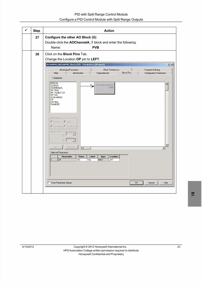
8/9/2019 Student Course Book- Automation
http://slidepdf.com/reader/full/student-course-book-automation 519/1165
PID with Split Range Control Module
Configure a PID Control Module with Split Range Outputs
4/13/2012 Copyright © 2012 Honeywell International Inc. 23
HPS Automation College written permission required to distributeHoneywell Confidential and Proprietary
Step Action
27 Configure the other AO Block (G)
Double-click the AOChannelA_1 block and enter the following:
Name: PVB
28 Click on the Block Pins Tab.
Change the Location OP pin to LEFT .

8/9/2019 Student Course Book- Automation
http://slidepdf.com/reader/full/student-course-book-automation 520/1165
PID with Split Range Control Module
Configure a PID Control Module with Split Range Outputs
24 Copyright © 2012 Honeywell International Inc. 4/13/2012
HPS Automation College written permission required to distributeHoneywell Confidential and Proprietary
Step Action
29 Assign the AO Channel to an AO Module.
For C200E:
Step Action
1 Refer to ‘Appendix 1 – C200E I/O list assignments’ at theend of Appendix for the following information on11_PC16.PVB:Module Name:
Channel Number:
2 Click on the Main Tab.
3 In the properties of the AO channel (PVB block), use thepull-down list to select the module name.
4 Select the channel number.
5 Click the ‘ Assign Channel Block ’ button.
6 Click the OK button to close PVB properties.
For C300:
Step Action
5 Refer to ‘Appendix 1 – C300 I/O list assignments’ at the endof Appendix for the following information on 11_PC16.PVB:Module Name:
Channel Number:
6 Click the OK button to close PVB properties.
7 Right-click the AO channel (PVB block) and select FunctionBlock Assign .
8 In the ‘Function Block Assignment Dialog’, select the
appropriate channel (use the Module Name (IOM Name),and the Channel Number from above), and click the Assign button.

8/9/2019 Student Course Book- Automation
http://slidepdf.com/reader/full/student-course-book-automation 521/1165
PID with Split Range Control Module
Configure a PID Control Module with Split Range Outputs
4/13/2012 Copyright © 2012 Honeywell International Inc. 25
HPS Automation College written permission required to distributeHoneywell Confidential and Proprietary
Step Action
30 Wire the connections as shown below :
If necessary, change the block pin positions from the Block Pin tab in the Configurationdetail form of each block.
ATTENTION
The screen capture might look different if you areusing Series C I/O
31 Save the Project chart form.

8/9/2019 Student Course Book- Automation
http://slidepdf.com/reader/full/student-course-book-automation 522/1165
PID with Split Range Control Module
Configure a PID Control Module with Split Range Outputs
26 Copyright © 2012 Honeywell International Inc. 4/13/2012
HPS Automation College written permission required to distributeHoneywell Confidential and Proprietary
Step Action
32 Configure the History collection.
Double-click in a blank space of the 11_PC16 project chart to open the configurationform.
Click the Server History Tab.1.) Historize the following parameters as shown below:
11_PC16.PIDA.PV; 11_PC16.PIDA.OP; 11_PC16.PVA.OP & 11_PC16.PVB.OP

8/9/2019 Student Course Book- Automation
http://slidepdf.com/reader/full/student-course-book-automation 523/1165
PID with Split Range Control Module
Configure a PID Control Module with Split Range Outputs
4/13/2012 Copyright © 2012 Honeywell International Inc. 27
HPS Automation College written permission required to distributeHoneywell Confidential and Proprietary
Step Action
33 Configure Trends and Groups.
Click Server Displays and add the following data:
Trend # 3 Pen # 3 Trend Parameter: 11_PC16.PIDA.PV
Group # 13 Pos # 3 Group Parameter: 11_PC16.PIDA.PV
Click OK .
34 Save and close the CM 11_PC16 .
35Select 11_PC16 , 11_HC41 , and 11_HC44 in the Project tree window and click thebutton.
36 Click Continue in the Load Window.
37 Select the Automatically change ………. checkbox in the Load dialog box.
ATTENTION
The Post load state is selected as ACTIVE by default.

8/9/2019 Student Course Book- Automation
http://slidepdf.com/reader/full/student-course-book-automation 524/1165
PID with Split Range Control Module
Configure a PID Control Module with Split Range Outputs
28 Copyright © 2012 Honeywell International Inc. 4/13/2012
HPS Automation College written permission required to distributeHoneywell Confidential and Proprietary
Step Action
38 Click OK to download.
ATTENTION
The download window closes automatically if theconfiguration contains no warnings or errors.
39 Open the Debutanizer_123 graphic in Station.
40 Verify the 11_PC16 controller is in AUTO mode and enter a set point of 1170 .
Select 11_HC41 and 11_HC44 and enter a 1 in the value input box.
ATTENTION
If the value of PV is not changing to the new SP, close theTie_Back_New Excel spreadsheet and re-open it.
Notice 11_PC16 SP is 1170 and the PV value is adjusting to the SP.

8/9/2019 Student Course Book- Automation
http://slidepdf.com/reader/full/student-course-book-automation 525/1165
PID with Split Range Control Module
Configure a PID Control Module with Split Range Outputs
4/13/2012 Copyright © 2012 Honeywell International Inc. 29
HPS Automation College written permission required to distributeHoneywell Confidential and Proprietary
Step Action
41 Go to Group 13 to view the details of 11_PC16 :

8/9/2019 Student Course Book- Automation
http://slidepdf.com/reader/full/student-course-book-automation 526/1165
PID with Split Range Control Module
Configure a PID Control Module with Split Range Outputs
30 Copyright © 2012 Honeywell International Inc. 4/13/2012
HPS Automation College written permission required to distributeHoneywell Confidential and Proprietary
Step Action
42 Change the SP to 1180 .
The controller takes the new SP value and increases the PV towards the SP as shownbelow:
You can watch the change by going to Trend number 3 on Station.
43 Change the SP to 935 and let 11_PC16 control to the new SP.

8/9/2019 Student Course Book- Automation
http://slidepdf.com/reader/full/student-course-book-automation 527/1165
PID with Split Range Control Module
Configure a PID Control Module with Split Range Outputs
4/13/2012 Copyright © 2012 Honeywell International Inc. 31
HPS Automation College written permission required to distributeHoneywell Confidential and Proprietary
Step Action
44 Open Control Builder in the Monitoring Mode.
Double-click 11_PC16 to open the chart view as shown below:
In the above example, PIDA OP is 51.73, that is, it’s between 50 and 100%.Based on the logic, PVA is CLOSED (OP= 0)PVB is OPENED (OP = 3.47)
ATTENTION
Values seen in this figure may differ from that seen onyour screen

8/9/2019 Student Course Book- Automation
http://slidepdf.com/reader/full/student-course-book-automation 528/1165
PID with Split Range Control Module
Configure a PID Control Module with Split Range Outputs
32 Copyright © 2012 Honeywell International Inc. 4/13/2012
HPS Automation College written permission required to distributeHoneywell Confidential and Proprietary
Step Action
45 Change PIDA to MAN Mode and change OP to 50%. • PVA and PVB are both closed.
Change PIDA OP to 0%• PVA will OPEN 100% .• PVB is CLOSED .
Change PIDA OP as 100%• PVA will CLOSE. • PVB will OPEN 100% .
46 Change the PIDA mode back to AUTO .

8/9/2019 Student Course Book- Automation
http://slidepdf.com/reader/full/student-course-book-automation 529/1165
4/13/2012 Copyright © 2012 Honeywell International Inc. 1
HPS Automation College written permission required to distributeHoneywell Confidential and Proprietary
Topic: Cascade PID Control Module
Contents
Configure a Cascade PID Control Module ............................................................................................ 3

8/9/2019 Student Course Book- Automation
http://slidepdf.com/reader/full/student-course-book-automation 530/1165
2 Copyright © 2012 Honeywell International Inc. 4/13/2012
HPS Automation College written permission required to distributeHoneywell Confidential and Proprietary
This page was intentionally left blank.
8/9/2019 Student Course Book- Automation
http://slidepdf.com/reader/full/student-course-book-automation 531/1165
Cascade PID Control Module
Configure a Cascade PID Control Module
4/13/2012 Copyright © 2012 Honeywell International Inc. 3
HPS Automation College written permission required to distributeHoneywell Confidential and Proprietary
Configure a Cascade PID Control Module
Practice
Objective
Configure a cascade controller for the T-100 bottom level control.
Prerequisites
• Experion PKS Server or a Client machine with Experion PKS Engineering Tools loaded
• The Debutanizer_123 graphic loaded on the Server (This is required at a later time to checkthe control strategy.)
• Control Builder running with one or two Project/Monitor tree windows open
• SIM-C200E/C200E, or SIM-C300/C300 Controller and IOMs configured• Excel Data Exchange open with the simulation spread sheet loaded

8/9/2019 Student Course Book- Automation
http://slidepdf.com/reader/full/student-course-book-automation 532/1165
Cascade PID Control Module
Configure a Cascade PID Control Module
4 Copyright © 2012 Honeywell International Inc. 4/13/2012
HPS Automation College written permission required to distributeHoneywell Confidential and Proprietary
Introduction
The first Cascade loop built is 11_LC14, the T-100 bottom level control. Although the loop has twosecondaries, 11_FC17 and 11_FC18, in this lab the cascade is built with just 11_FC17. 11_ FC18 is
configured in the next lab.The P&ID shows that this loop has an interlock with the bottom safety valve and is the primary to
both outlet streams (11_FC17 and 11_FC18).
LSD15 is driven by interlock logic. The interlock (11_LSD15) will be imported into the project.
The cascade loop, with 11_LC14 as primary and 11_FC17 as secondary, will be built, anddownloaded in this lab. However, the functionality will be tested after the next lab when 11_FC18is added to project. The loops require a bumpless transfer from MAN to AUTO to CAS.
.
The following CMs will be configured:
CM Name Action to be taken
11_LC14 & 11_FC17 Configure as a simple cascade loop.
11_LSD15 Imported from:C:\Users\Public\Public Documents\Honeywell\Experion PKS\IXPORT\Student_DB\Series_A (or
_C)
Modify 11_LC14 Add logic to check when level goes above 5%.
Perform the following procedures in Control Builder.

8/9/2019 Student Course Book- Automation
http://slidepdf.com/reader/full/student-course-book-automation 533/1165
Cascade PID Control Module
Configure a Cascade PID Control Module
4/13/2012 Copyright © 2012 Honeywell International Inc. 5
HPS Automation College written permission required to distributeHoneywell Confidential and Proprietary
Procedure
Create a Control Module (CM)
Step Action1 Open Control Builder from Configuration Studio, if not already open.
2 Open the Project tree window in the upper left hand corner and the Library tree windowin the lower left hand corner.

8/9/2019 Student Course Book- Automation
http://slidepdf.com/reader/full/student-course-book-automation 534/1165
Cascade PID Control Module
Configure a Cascade PID Control Module
6 Copyright © 2012 Honeywell International Inc. 4/13/2012
HPS Automation College written permission required to distributeHoneywell Confidential and Proprietary
Step Action
3 Build a new CM.
Drag a Control Module from the Library tab to the CEE in the Project window
ATTENTION
This creates a new Control Module and also assigns the CMto the CEE.
Drag here

8/9/2019 Student Course Book- Automation
http://slidepdf.com/reader/full/student-course-book-automation 535/1165
Cascade PID Control Module
Configure a Cascade PID Control Module
4/13/2012 Copyright © 2012 Honeywell International Inc. 7
HPS Automation College written permission required to distributeHoneywell Confidential and Proprietary
Step Action
4 Enter 11_LC14 in the Destination Tagnames textbox and 11_LC14_Item in theDestination Item Names textbox.
Click Finish .

8/9/2019 Student Course Book- Automation
http://slidepdf.com/reader/full/student-course-book-automation 536/1165
Cascade PID Control Module
Configure a Cascade PID Control Module
8 Copyright © 2012 Honeywell International Inc. 4/13/2012
HPS Automation College written permission required to distributeHoneywell Confidential and Proprietary
Step Action
5 Configure the parameters for 11_LC14.
Open 11_LC14 in Chart View.
Double-click the chart view to open the configuration form.
Enter the following details under the Main tab.
Name: 11_LC14
Item Name: 11_LC14_item
Parent Asset: Level_C11
Description T-100 Debutanizer Bottom Lvl Controller
Engr Units: %
Accept the defaults for any remaining parameters on this tab.
6 Click the Server Displays tab and enter the following display details:
Point Detail Display: sysDtlPIDA
Click OK .
ATTENTION
The Group detail display for 11_LC14 in Station will be directlypicked from the type of Point detail display specified.

8/9/2019 Student Course Book- Automation
http://slidepdf.com/reader/full/student-course-book-automation 537/1165
Cascade PID Control Module
Configure a Cascade PID Control Module
4/13/2012 Copyright © 2012 Honeywell International Inc. 9
HPS Automation College written permission required to distributeHoneywell Confidential and Proprietary
Add Function Blocks to a CM
After creating the CM, design a control strategy by adding relevant Input/Output blocks and Controlblocks (like PID, device control, or logic blocks).
The IOMs configured in the Configure C200E Hardware and Series A IOM / Configure C300 Hardware andSeries C IOM lab are used here.
Step Action
1 Add the following function blocks from the Library tab of Control Builder according to thesequence shown below.
Block Family Block
IOCHANNEL or
SERIES_C_IO AI-HL AICHANNELA (A)
DATAACQ DATAACQ (B)
REGCTL PID (C)• CM 11_LC14 should resemble the following diagram:
ATTENTION
The screen capture might look different if you are using Series C I/O
A
C
B
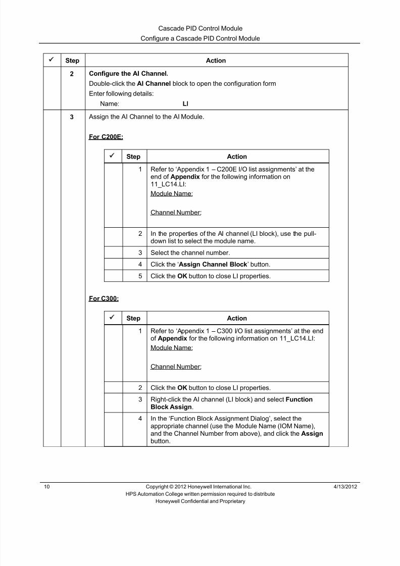
8/9/2019 Student Course Book- Automation
http://slidepdf.com/reader/full/student-course-book-automation 538/1165
Cascade PID Control Module
Configure a Cascade PID Control Module
10 Copyright © 2012 Honeywell International Inc. 4/13/2012
HPS Automation College written permission required to distributeHoneywell Confidential and Proprietary
Step Action
2 Configure the AI Channel.
Double-click the AI Channel block to open the configuration form
Enter following details:
Name: LI
3 Assign the AI Channel to the AI Module.
For C200E:
Step Action
1 Refer to ‘Appendix 1 – C200E I/O list assignments’ at theend of Appendix for the following information on11_LC14.LI:Module Name:
Channel Number:
2 In the properties of the AI channel (LI block), use the pull-down list to select the module name.
3 Select the channel number.
4 Click the ‘ Assign Channel Block ’ button.
5 Click the OK button to close LI properties.
For C300:
Step Action
1 Refer to ‘Appendix 1 – C300 I/O list assignments’ at the endof Appendix for the following information on 11_LC14.LI:Module Name:
Channel Number:
2 Click the OK button to close LI properties.
3 Right-click the AI channel (LI block) and select FunctionBlock Assign .
4 In the ‘Function Block Assignment Dialog’, select theappropriate channel (use the Module Name (IOM Name),and the Channel Number from above), and click the Assign button.

8/9/2019 Student Course Book- Automation
http://slidepdf.com/reader/full/student-course-book-automation 539/1165
Cascade PID Control Module
Configure a Cascade PID Control Module
4/13/2012 Copyright © 2012 Honeywell International Inc. 11
HPS Automation College written permission required to distributeHoneywell Confidential and Proprietary
Step Action
4 Configure a Data Acquisition Block (B).
Double-click the Data Acquisition Block to open the configuration form.
Enter following details:
Name: DACA
Description: T-100 Debutanizer Bottom Level
Engr Units: %
PV Character LINEAR
PVEU Range Hi: 100
PVEU Range Lo: 0
PV Extended Hi Limit: 102.9
PV Extended Lo Limit: -2.9
Clamping Option: ENABLE
Accept the defaults for any remaining parameters on this tab .

8/9/2019 Student Course Book- Automation
http://slidepdf.com/reader/full/student-course-book-automation 540/1165
Cascade PID Control Module
Configure a Cascade PID Control Module
12 Copyright © 2012 Honeywell International Inc. 4/13/2012
HPS Automation College written permission required to distributeHoneywell Confidential and Proprietary
Step Action
5 Configure Alarms for the DACA Block.
Click the Alarms tab.
Enter the following:
PV High Trip Point: 98 Priority: HIGH
PV Low Trip Point: 1 Priority: LOW
Accept the defaults for any remaining parameters.
Click OK .

8/9/2019 Student Course Book- Automation
http://slidepdf.com/reader/full/student-course-book-automation 541/1165
Cascade PID Control Module
Configure a Cascade PID Control Module
4/13/2012 Copyright © 2012 Honeywell International Inc. 13
HPS Automation College written permission required to distributeHoneywell Confidential and Proprietary
Step Action
6 Configure a PID Block (C).
Double-click PIDA .
Enter the following details:
Name: PIDA
Description: T-100 Debutanizer Bottom Level
Engineering Units: %
PVEU Range Hi: 100
PVEU Range Low: 0
Enable SecondaryInitialization Option checkbox: Check
Normal Mode: AUTO
Normal Mode Attribute: OPERATOR
Accept the defaults for any remaining parameters on this tab .

8/9/2019 Student Course Book- Automation
http://slidepdf.com/reader/full/student-course-book-automation 542/1165
Cascade PID Control Module
Configure a Cascade PID Control Module
14 Copyright © 2012 Honeywell International Inc. 4/13/2012
HPS Automation College written permission required to distributeHoneywell Confidential and Proprietary
Step Action
7 Click the Algorithm tab in the PID configuration form
Enter the following details :
Control Equation Type: EQB
Control Action: DIRECT
Integral Time (T1): 0.4
Linear Gain Options: LIN
Overall Gain: 0.4
8 Click the SetPoint tab.
Enter the following details :
High Limit: 100
Low Limit: 0

8/9/2019 Student Course Book- Automation
http://slidepdf.com/reader/full/student-course-book-automation 543/1165
Cascade PID Control Module
Configure a Cascade PID Control Module
4/13/2012 Copyright © 2012 Honeywell International Inc. 15
HPS Automation College written permission required to distributeHoneywell Confidential and Proprietary
Step Action
9 Click the Alarms tab.
Enter the following details:
OP High Trip Point: 98 Priority: HIGH
OP Low Trip Point: 1 Priority: LOW
Accept the defaults for any remaining parameters on this tab.
10 Click the Output tab
In the Control Variable section enter the following:
CVEU Range Hi: 385
CVEU Range Low: 0 − For a primary loop the CVEU limits are the range limits of the secondary
controller PV.
Accept the defaults for any remaining parameters.
Click OK.

8/9/2019 Student Course Book- Automation
http://slidepdf.com/reader/full/student-course-book-automation 544/1165
Cascade PID Control Module
Configure a Cascade PID Control Module
16 Copyright © 2012 Honeywell International Inc. 4/13/2012
HPS Automation College written permission required to distributeHoneywell Confidential and Proprietary
Step Action
11 Arrange the function blocks as shown.
If necessary, change the block pin positions from the Block Pin tab in the Configurationdetail form of each block.
Connect the block pins as shown.Save and Close 11_LC14.
ATTENTION
The screen capture might look different if you are using Series C I/O
12 Configure 11_FC17.
The following procedure configures 11_FC17 by copying then modifying 11_LC14.
Right-click 11_LC14 in Project tree.Select the Copy option.
Enter:
Destination Tagnames: 11_FC17
Destination Item Names: 11_FC17_item
Click Next (or Finish) .

8/9/2019 Student Course Book- Automation
http://slidepdf.com/reader/full/student-course-book-automation 545/1165
Cascade PID Control Module
Configure a Cascade PID Control Module
4/13/2012 Copyright © 2012 Honeywell International Inc. 17
HPS Automation College written permission required to distributeHoneywell Confidential and Proprietary
Step Action
13 A message opens indicating that the channel assignment will not be retained.(You may or may not get this dialog box.)
Click Finish .
ATTENTION
Copying a CM retains all the blocks and connections except channelassignments.
14 Assign 11_FC17 to CEESCEFB61 (or SIM_CEEC300) .
Hint: Use the (Assign) button
15 Double-click 11_FC17 under CEESCEFB61 (For SIM-C200E) or SIM_CEEC300 (ForSIM-C300) to open the chart view.
16 Double-click the AICHANNEL (LI) block.
Enter the following:
Name: FT
17 For C300s ONLY:
Change the ranges of the FT block as follows:
PV Extended High Range 390
PV High Range 385
PV Low Range 0
PV Extended Low Range -9.6

8/9/2019 Student Course Book- Automation
http://slidepdf.com/reader/full/student-course-book-automation 546/1165
Cascade PID Control Module
Configure a Cascade PID Control Module
18 Copyright © 2012 Honeywell International Inc. 4/13/2012
HPS Automation College written permission required to distributeHoneywell Confidential and Proprietary
Step Action
18 Assign the AI Channel to an AI Module.
For C200E:
Step Action
1 Refer to ‘Appendix 1 – C200E I/O list assignments’ at theend of Appendix for the following information on11_FC17.FT:Module Name:
Channel Number:
2 In the properties of the AI channel (FT block), use the pull-
down list to select the module name.3 Select the channel number.
4 Click the ‘ Assign Channel Block ’ button.
5 Click the OK button to close FT properties.
For C300:
Step Action
1 Refer to ‘Appendix 1 – C300 I/O list assignments’ at the end
of Appendix for the following information on 11_FC17.FT:Module Name:
Channel Number:
2 Click the OK button to close FT properties.
3 Right-click the AI channel (FT block) and select FunctionBlock Assign .
4 In the ‘Function Block Assignment Dialog’, select theappropriate channel (use the Module Name (IOM Name),and the Channel Number from above), and click the Assign button.

8/9/2019 Student Course Book- Automation
http://slidepdf.com/reader/full/student-course-book-automation 547/1165
Cascade PID Control Module
Configure a Cascade PID Control Module
4/13/2012 Copyright © 2012 Honeywell International Inc. 19
HPS Automation College written permission required to distributeHoneywell Confidential and Proprietary
Step Action
19 Configure the DACA Block.
Double-click the DACA block.
Enter following:
Name: DACA
Description: T-100 Bottom to Storage Tank
Engr Units: m3/hr
PV Character: None
PVEU RangeHi: 385
PVEU Range Lo: 0
PV Extended Limits Hi: 390
PV Extended Limits Lo: -9.6
Clamping Option: ENABLE
Accept the defaults for any remaining parameters on this tab.

8/9/2019 Student Course Book- Automation
http://slidepdf.com/reader/full/student-course-book-automation 548/1165
Cascade PID Control Module
Configure a Cascade PID Control Module
20 Copyright © 2012 Honeywell International Inc. 4/13/2012
HPS Automation College written permission required to distributeHoneywell Confidential and Proprietary
Step Action
20 Click the Alarms tab.
Change the alarm setting as given below :
PV High Trip Point: 375 Priority: LOW
Click OK .

8/9/2019 Student Course Book- Automation
http://slidepdf.com/reader/full/student-course-book-automation 549/1165
Cascade PID Control Module
Configure a Cascade PID Control Module
4/13/2012 Copyright © 2012 Honeywell International Inc. 21
HPS Automation College written permission required to distributeHoneywell Confidential and Proprietary
Step Action
21 Configure a PID function block.
Double-click PIDA .
Enter following details:
Name: PIDA
Description: T-100 Bottom to Storage Tank Flow
Engineering Units: m3/hr
PVEU Range Hi: 385
PVEU Range Low: 0
Enable Secondary InitializationOption checkbox: Check
Normal Mode and Mode: CAS
Normal Mode Attribute: NONE
Mode Attribute : OPERATOR
Accept the defaults for any remaining parameters on this tab.

8/9/2019 Student Course Book- Automation
http://slidepdf.com/reader/full/student-course-book-automation 550/1165
Cascade PID Control Module
Configure a Cascade PID Control Module
22 Copyright © 2012 Honeywell International Inc. 4/13/2012
HPS Automation College written permission required to distributeHoneywell Confidential and Proprietary
Step Action
22 Click the Algorithm tab in the PID confiuration form.
Enter following details:
Control Equation Type: EQB
Control Action : REVERSE
Integral Time (T1): 0.8
Linear Gain Options: LIN
Overall gain: 0.22
23 Click the SetPoint tab.
Enter following details:
High Limit: 385
Low Limit: 0
24 Click the Alarms tab.
Enter the following details:
OP High: 98
OP Low: 0
Leave the priority settings unchanged.Click OK .

8/9/2019 Student Course Book- Automation
http://slidepdf.com/reader/full/student-course-book-automation 551/1165
Cascade PID Control Module
Configure a Cascade PID Control Module
4/13/2012 Copyright © 2012 Honeywell International Inc. 23
HPS Automation College written permission required to distributeHoneywell Confidential and Proprietary
Step Action
25 ADD an AO Channel from the Library tab
IOCHANNEL > AOCHANNEL (Series A) or
SERIES_C_IO AO (Series C)
Double-click AOCHANNELA .
Enter the following:
Channel Name: FY

8/9/2019 Student Course Book- Automation
http://slidepdf.com/reader/full/student-course-book-automation 552/1165
Cascade PID Control Module
Configure a Cascade PID Control Module
24 Copyright © 2012 Honeywell International Inc. 4/13/2012
HPS Automation College written permission required to distributeHoneywell Confidential and Proprietary
Step Action
26 Assign the AO block to an AO channel.
For C200E:
Step Action
1 Refer to ‘Appendix 1 – C200E I/O list assignments’ at theend of Appendix for the following information on11_FC17.FY:Module Name:
Channel Number:
2 In the properties of the AO channel (FY block), use the pull-
down list to select the module name.3 Select the channel number.
4 Click the ‘ Assign Channel Block ’ button.
5 Click the OK button to close FY properties.
For C300:
Step Action
1 Refer to ‘Appendix 1 – C300 I/O list assignments’ at the end
of Appendix for the following information on 11_FC17.FY:Module Name:
Channel Number:
2 Click the OK button to close FY properties.
3 Right-click the AO channel (FY block) and select FunctionBlock Assign .
4 In the ‘Function Block Assignment Dialog’, select theappropriate channel (use the Module Name (IOM Name),and the Channel Number from above), and click the Assign button.

8/9/2019 Student Course Book- Automation
http://slidepdf.com/reader/full/student-course-book-automation 553/1165
Cascade PID Control Module
Configure a Cascade PID Control Module
4/13/2012 Copyright © 2012 Honeywell International Inc. 25
HPS Automation College written permission required to distributeHoneywell Confidential and Proprietary
Step Action
27 Wire 11_FC17.PIDA.OP to 11_FC17.FY.OP .
28Select Chart > Insert > Parameter Connector or click the button on the toolbar.
Add 11_LC14.PIDA.OP to 11_FC17.PIDA.SP with a parameter connection as shownbelow.
For detailed instructions, go to Knowledge Builder :Experion R400 > Configuration > Control Building User’s Guide > Control BuilderOperations >Creating a control module>Connecting and Disconnecting Blocks >Connecting Blocks with Parameter Connector Option .
• This connection configures the 11_FC17 controller as a secondary controllerreceiving the set point from the primary controller, 11_LC14 . That is why the normal
mode of the 11_FC17 PID block is defined as cascade
ATTENTION
The screen capture might look different if you areusing Series C I/O
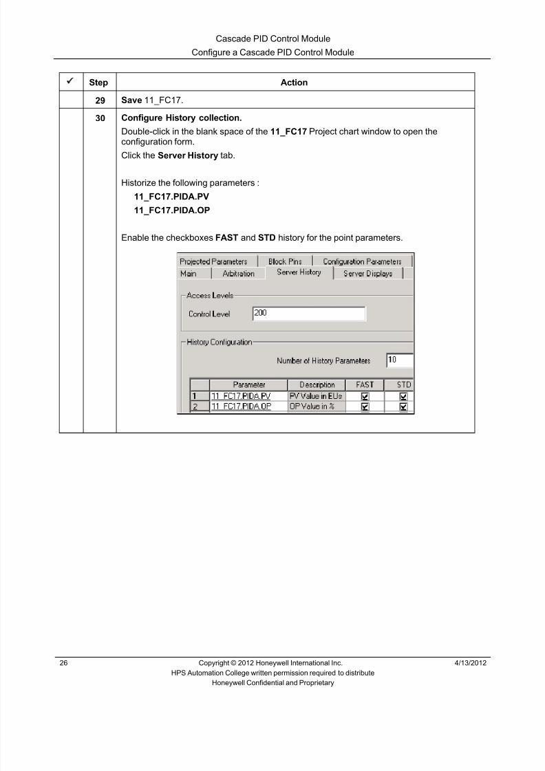
8/9/2019 Student Course Book- Automation
http://slidepdf.com/reader/full/student-course-book-automation 554/1165
Cascade PID Control Module
Configure a Cascade PID Control Module
26 Copyright © 2012 Honeywell International Inc. 4/13/2012
HPS Automation College written permission required to distributeHoneywell Confidential and Proprietary
Step Action
29 Save 11_FC17.
30 Configure History collection.
Double-click in the blank space of the 11_FC17 Project chart window to open theconfiguration form.
Click the Server History tab.
Historize the following parameters :
11_FC17.PIDA.PV
11_FC17.PIDA.OP
Enable the checkboxes FAST and STD history for the point parameters.

8/9/2019 Student Course Book- Automation
http://slidepdf.com/reader/full/student-course-book-automation 555/1165
Cascade PID Control Module
Configure a Cascade PID Control Module
4/13/2012 Copyright © 2012 Honeywell International Inc. 27
HPS Automation College written permission required to distributeHoneywell Confidential and Proprietary
Step Action
31 Configure Trends and Groups.
Click the Server Displays tab.
Configure the following:
Trend # 4, Pen 4, Add parameter 11_FC17.PIDA.PV
Group # 11, Pos # 4, Add parameter 11_FC17.PIDA.OP
Click OK .
32 Save and Close 11_FC17.

8/9/2019 Student Course Book- Automation
http://slidepdf.com/reader/full/student-course-book-automation 556/1165
Cascade PID Control Module
Configure a Cascade PID Control Module
28 Copyright © 2012 Honeywell International Inc. 4/13/2012
HPS Automation College written permission required to distributeHoneywell Confidential and Proprietary
Add Logic to 11_LC14 to check if the level is greater than 5%
Logic blocks are added to 11_LC14 to check if the level in T-100 is greater than 5%.
Step Action
1 Open 11_LC14 in chart view.
2 Add the following function blocks from the Library tab of Control Builder according to thefollowing sequence:
Block Family Block
LOGIC GE (D)
UTILITY NUMERIC (E)• (D) = GE : This Greater than or Equal to block checks if the designated input (IN[1]) is
greater than or equal to a second input (IN[2])− Use the GE to check if the T-100 level is greater than 5% by checking the
level with a fixed value of 5 given in the numeric block− The output of GE is further used in the interlock logic of 11_LSD15, which is
imported later• (E) = NUMERIC : This NUMERIC block stores up to 8 bytes of floating point values
within a defined upper and lower limit for use in a control strategy. We will use thenumeric to hold a fixed value for the GE block to use as an input
3 Configure the GE block.
Double-click the GE function block.
Verify the parameters as shown below. Accept the defaults for any remainingparameters.
Click OK .

8/9/2019 Student Course Book- Automation
http://slidepdf.com/reader/full/student-course-book-automation 557/1165
Cascade PID Control Module
Configure a Cascade PID Control Module
4/13/2012 Copyright © 2012 Honeywell International Inc. 29
HPS Automation College written permission required to distributeHoneywell Confidential and Proprietary
Step Action
4 Double-click the NUMERICA function block.
Enter the following:
Name: LL_Comparator
Actual Value: 5
Accept the defaults for any remaining parameters.
Click OK .

8/9/2019 Student Course Book- Automation
http://slidepdf.com/reader/full/student-course-book-automation 558/1165
Cascade PID Control Module
Configure a Cascade PID Control Module
30 Copyright © 2012 Honeywell International Inc. 4/13/2012
HPS Automation College written permission required to distributeHoneywell Confidential and Proprietary
Step Action
5 Arrange the parameter connector wire, 11_LC14.DACA.PV , to IN[1] in the GEA block
Arrange the PV pin wire of the NUMERICA block to the IN[2] of the GEA Block.• When 11_LC14.DACA.PV is >= 5, the OUT pin of GEA block is set ON. This pin is
used in the logic of 11_LSD15 to reset an Open/Closed flag
6 Save the CM.

8/9/2019 Student Course Book- Automation
http://slidepdf.com/reader/full/student-course-book-automation 559/1165
Cascade PID Control Module
Configure a Cascade PID Control Module
4/13/2012 Copyright © 2012 Honeywell International Inc. 31
HPS Automation College written permission required to distributeHoneywell Confidential and Proprietary
Step Action
7 Configure History Collection.
Double-click a blank space in the 11_LC14 Project chart window, to open theconfiguration form.
Click the Server History Tab.Historize the following parameters:
11_LC14.PIDA.PV
11_LC14.PIDA.OP
11_LC14.GEA.OUT
8 Configure Trends and Groups.
Click the Server Displays tab.
Trends sectionTrend # 1, Pen 3, Add parameter 11_LC14.PIDA.PV
Groups section
Group # 11, Pos # 3, Add parameter 11_LC14.PIDA.OP
Click OK .

8/9/2019 Student Course Book- Automation
http://slidepdf.com/reader/full/student-course-book-automation 560/1165
Cascade PID Control Module
Configure a Cascade PID Control Module
32 Copyright © 2012 Honeywell International Inc. 4/13/2012
HPS Automation College written permission required to distributeHoneywell Confidential and Proprietary
Step Action
9 Save and Close 11_LC14.
10 Import (with CEE assignment) CM 11_LSD15 from:
C:\ Users\Public\Public Documents\Honeywell\Experion PKS \IXPORT\Student_DB\Series_A (or _C)
ATTENTION
In the next lab, you will import a calculation Control Module thatwill provide additional process connections and the simulationrequired for 11_LC14.
If you are Using SIMC200E/C200E the path for Database isC:\ Users\Public\Public Documents\Honeywell\Experion PKS\IXPORT\Student_DB\Series_A
If you are Using SIMC300/C300 the path for Database isC:\ Users\Public\Public Documents\Honeywell\Experion PKS\IXPORT\Student_DB\Series_C
11 Open the Project tree, select 11_FC17, 11_LC14, and 11_LSD15 with the <CTRL> key
and click in the toolbar to download the three CMs.• Click Continue in the Load window• Select the Automatically change……. checkbox and click OK .• After downloading, select the Monitoring tab and verify all the CMs are active
(green)
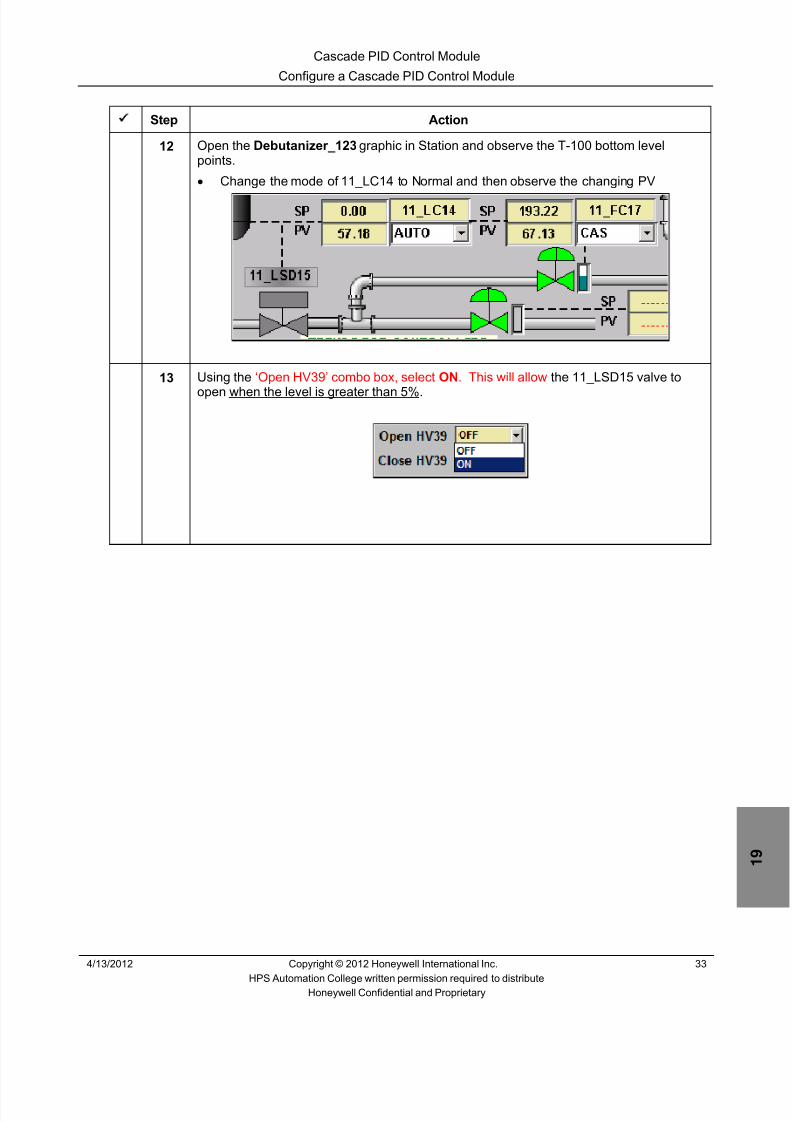
8/9/2019 Student Course Book- Automation
http://slidepdf.com/reader/full/student-course-book-automation 561/1165
Cascade PID Control Module
Configure a Cascade PID Control Module
4/13/2012 Copyright © 2012 Honeywell International Inc. 33
HPS Automation College written permission required to distributeHoneywell Confidential and Proprietary
Step Action
12 Open the Debutanizer_123 graphic in Station and observe the T-100 bottom levelpoints.• Change the mode of 11_LC14 to Normal and then observe the changing PV
13 Using the ‘Open HV39’ combo box, select ON . This will allow the 11_LSD15 valve to
open when the level is greater than 5%.

8/9/2019 Student Course Book- Automation
http://slidepdf.com/reader/full/student-course-book-automation 562/1165
Cascade PID Control Module
Configure a Cascade PID Control Module
34 Copyright © 2012 Honeywell International Inc. 4/13/2012
HPS Automation College written permission required to distributeHoneywell Confidential and Proprietary
Step Action
14 Change the 11_FC17 flow controller to MAN mode and double-click the SP value of11_LC14 to open the Point Detail page.
Observe that the Primary Controller 11_LC14 has now changed to INIT (the indication
appears next to the OP value, as shown below). Whenever the Secondary Controller isnot in Cascade Mode, initialization will be indicated as shown on the Primary Controller.

8/9/2019 Student Course Book- Automation
http://slidepdf.com/reader/full/student-course-book-automation 563/1165
4/13/2012 Copyright © 2012 Honeywell International Inc. 1
HPS Automation College written permission required to distributeHoneywell Confidential and Proprietary
Topic: Cascade PID with Two Secondaries
Contents
Configure a Cascade PID CM with Two Secondaries ........................................................................... 3

8/9/2019 Student Course Book- Automation
http://slidepdf.com/reader/full/student-course-book-automation 564/1165
2 Copyright © 2012 Honeywell International Inc. 4/13/2012
HPS Automation College written permission required to distributeHoneywell Confidential and Proprietary
This page was intentionally left blank.

8/9/2019 Student Course Book- Automation
http://slidepdf.com/reader/full/student-course-book-automation 565/1165
Cascade PID with Two Secondaries
Configure a Cascade PID CM with Two Secondaries
4/13/2012 Copyright © 2012 Honeywell International Inc. 3
HPS Automation College written permission required to distributeHoneywell Confidential and Proprietary
Configure a Cascade PID CM with Two Secondaries
Practice
Objective
• Configure a Cascade Loop with one primary and two secondaries for T-100 bottom levelcontrol
• Configure a FANOUT block to connect the primary controller’s output to the setpoint oftwo secondary controllers
• Configure an Auxcalc function block to calculate the flow at the outlet of T-100
Prerequisites
• Experion PKS Server or a client machine with Experion PKS Engineering Tools loaded
• Debutanizer_123 graphic loaded on the Server (This is required at a later time to check thecontrol strategy.)
• Control Builder running with one or two Project/Monitor tree windows open
• SIM-C200E/C200E or SIM-C300/C300 Controller and IOMs configured
• Excel Data Exchange open with the simulation spreadsheet loaded

8/9/2019 Student Course Book- Automation
http://slidepdf.com/reader/full/student-course-book-automation 566/1165
Cascade PID with Two Secondaries
Configure a Cascade PID CM with Two Secondaries
4 Copyright © 2012 Honeywell International Inc. 4/13/2012
HPS Automation College written permission required to distributeHoneywell Confidential and Proprietary
Introduction
In this lab, the 11_FC18 loop is added as a secondary to the 11_LC14 loop built in the previous lab.Similar considerations of operation apply; the loops require bumpless transfer from MAN to AUTO
or CAS.
• In addition, the ratio of the flow of 11_FC17 and 11_FC18 is 70:30
• The Control Module built in the previous lab will be modified, downloaded, and tested
• The remaining Control Modules will then be imported into Project, downloaded and activated
The following CMs will be configured:
CM Name Action to be taken
11_LC14 Modify this CM to add a FANOUT block, used to connect theoutput to two secondary controllers and maintain a fixed flowratio between the two controller outputs.
11_FC17 Connect parameter 11_LC14.FANOUTA.OP(1) to11_FC17.PIDA.SP.
11_FC18 Copy and modify 11_FC17 as 11_FC18 and connect11_LC14.FANOUTA.OP(2) to 11_FC18.PIDA.SP.
Add an Auxcalc block for adding the flow through 11_FC17 and11_FC18.
11_AC12; 11_FC15;11_FC19; 11_FC20;11_LC16; 11_TC10
Import these CMs from:C:\Users\Public\Public Documents\Honeywell\Experion PKS\IXPORT\Student_DB\Series_A (or _C)

8/9/2019 Student Course Book- Automation
http://slidepdf.com/reader/full/student-course-book-automation 567/1165
Cascade PID with Two Secondaries
Configure a Cascade PID CM with Two Secondaries
4/13/2012 Copyright © 2012 Honeywell International Inc. 5
HPS Automation College written permission required to distributeHoneywell Confidential and Proprietary
Perform the following procedures in Control Builder.
Create a Control Module (CM)
Step Action
1 Open Control Builder from Configuration Studio , if not already open.
2 Double-click CM 11_FC17, to open the chart view in the Project window.
3 Delete the the wiring which connects 11_LC14.PIDA.OP (Parameter Connector) to11_FC17.PIDA.SP .
11_FC17 will be as follows:
ATTENTION
This is to facilitate the connection of the FANOUTblock to the 11_LC14.PIDA.OP .
The AI and AO channel block might look different ifyou are using Series C I/O

8/9/2019 Student Course Book- Automation
http://slidepdf.com/reader/full/student-course-book-automation 568/1165
Cascade PID with Two Secondaries
Configure a Cascade PID CM with Two Secondaries
6 Copyright © 2012 Honeywell International Inc. 4/13/2012
HPS Automation College written permission required to distributeHoneywell Confidential and Proprietary
Step Action
4 Save and Close 11_FC17.
5 From the Project tab, double-click 11_LC14 to open the Chart view.
6 Select the Library Tree window.
7 Add the following block to CM 11_LC14.
Block Family Block
REGCTL FANOUT
8 Double-click the FANOUTA block.
Enter the following details in the Main tab:
Name: FANOUTA
Description: T-100 Debutanizer bottoms
High Limit: 385
Normal Mode: CAS
Mode: CAS
Mode Attribute: OPERATOR

8/9/2019 Student Course Book- Automation
http://slidepdf.com/reader/full/student-course-book-automation 569/1165
Cascade PID with Two Secondaries
Configure a Cascade PID CM with Two Secondaries
4/13/2012 Copyright © 2012 Honeywell International Inc. 7
HPS Automation College written permission required to distributeHoneywell Confidential and Proprietary
Step Action
9 Click the Individual Output tab.
Enter the following details:
Output #1 Gain: 0.7 (Op1 will be 70% of the input signal.)
Output #2 Gain: 0.3 (Op2 will be 30% of the input signal.)
Verify the Enable Secondary Initialization Option checkboxes are selected for Output#1 and Output #2.
Clear the checkboxes for all other outputs.
Click OK .
ATTENTION
Output Gain values are not accessible throughgraphics. If they need an online change, use theMonitoring mode in Control Builder. This is explainedlater in this module.

8/9/2019 Student Course Book- Automation
http://slidepdf.com/reader/full/student-course-book-automation 570/1165
Cascade PID with Two Secondaries
Configure a Cascade PID CM with Two Secondaries
8 Copyright © 2012 Honeywell International Inc. 4/13/2012
HPS Automation College written permission required to distributeHoneywell Confidential and Proprietary
Step Action
10 Wire 11_LC14.PIDA.OP to 11_LC14.FANOUTA.X1 .• CM 11_LC14 should appear similar to the one shown below • Change the Block pin positions, if required
ATTENTION
In this picture the GEA and Numeric block are not shown.
11 Save and Close the CM.
12 Double-click 11_FC17 to open the Chart view.

8/9/2019 Student Course Book- Automation
http://slidepdf.com/reader/full/student-course-book-automation 571/1165
Cascade PID with Two Secondaries
Configure a Cascade PID CM with Two Secondaries
4/13/2012 Copyright © 2012 Honeywell International Inc. 9
HPS Automation College written permission required to distributeHoneywell Confidential and Proprietary
Step Action
13 Wire parameter 11_LC14.FANOUTA.OP[1] to 11_FC17.PIDA.SP with the parameterconnector, as shown below:
14 Save and Close 11_FC17.
15 Right-click 11_FC17 in the Project tab and select copy .• Enter the Destination Tagname 11_FC18 and Destination Item Names
11_FC18_Item• Click the Next button.• Copying retains all the function blocks and parameters except the Input and
Output channel assignments (you may get a dialog box indicating the “Non-Retained items”).
• If the following error appears, Click Close.

8/9/2019 Student Course Book- Automation
http://slidepdf.com/reader/full/student-course-book-automation 572/1165
Cascade PID with Two Secondaries
Configure a Cascade PID CM with Two Secondaries
10 Copyright © 2012 Honeywell International Inc. 4/13/2012
HPS Automation College written permission required to distributeHoneywell Confidential and Proprietary
Step Action
16 Assign 11_FC18 to CEESCEFB61 (or SIM_CEEC300).
ATTENTION
When copying a CM, the new CM gets put in ‘Unassigned’.
17 Open chart view for 11_FC18 .
18 Configure the AIChannel block.
Double-click the AIChannel named FT
Enter following details:
Channel Name: FI
19 Refer to the appropriate (C200E or C300) table at the end of Appendix to determine the
correct module and channel for 11_FC18.FI.
For C200E: Assign 11_FC18.FI to the appropriate module and channel.Close the properties of the FI block.
For C300:Close the properties of the FI block.
Assign 11_FC18.FI to the appropriate module and channel.
20 Configure the AOChannel block.
Double-click the AOChannel named FY
Enter following details:
Channel Name: FV
21 Refer to the appropriate (C200E or C300) table at the end of Appendix to determine thecorrect module and channel for 11_FC18.FV.
For C200E: Assign 11_FC18.FV to the appropriate module and channel.Close the properties of the FV block.
For C300:Close the properties of the FV block.
Assign 11_FC18.FV to the appropriate module and channel.

8/9/2019 Student Course Book- Automation
http://slidepdf.com/reader/full/student-course-book-automation 573/1165
Cascade PID with Two Secondaries
Configure a Cascade PID CM with Two Secondaries
4/13/2012 Copyright © 2012 Honeywell International Inc. 11
HPS Automation College written permission required to distributeHoneywell Confidential and Proprietary
Step Action
22 Modify the PID block.
In the Algorithm tab, change T1 to 0.9 and the Overall Gain to 0.2
Accept the defaults for any remaining parameters.
Click OK .
23 Wire the parameter 11_LC14.FANOUTA.OP [2] to 11_FC18.PIDA.SP with a parameterconnector, as shown below.
24Click icon to Save 11_FC18 CM.
25 Add an AUXCALC block to 11_FC18.
Select the Library tab and add the following function block.
Block Family Block AUXILIARY AUXCALC

8/9/2019 Student Course Book- Automation
http://slidepdf.com/reader/full/student-course-book-automation 574/1165
Cascade PID with Two Secondaries
Configure a Cascade PID CM with Two Secondaries
12 Copyright © 2012 Honeywell International Inc. 4/13/2012
HPS Automation College written permission required to distributeHoneywell Confidential and Proprietary
Step Action
26 Double-click the AUXCALCA block.
Enter following details:
Name: FLOW_CALC
Description: T-100 Bottom Flow
Engr Units: m3/hr
Assignable Outputs PV Selection : C[1]
Accept the defaults for any remaining parameters on this tab.

8/9/2019 Student Course Book- Automation
http://slidepdf.com/reader/full/student-course-book-automation 575/1165
Cascade PID with Two Secondaries
Configure a Cascade PID CM with Two Secondaries
4/13/2012 Copyright © 2012 Honeywell International Inc. 13
HPS Automation College written permission required to distributeHoneywell Confidential and Proprietary
Step Action
27 Add new pins to the FLOW_CALC block.
Click the Block Pins tab.
Select P from the Parameters window.
Select the Pin Position as Input .
Select the Array Indices as 1 for P[1] and then Add parameter P[1], as shown below.
Select the Array Indices as 2 for P[2] and then Add parameter P[2], as shown below.
Change the Location of the Pins, as shown in the display.
Click OK .
ATTENTION
The AUXCALC block evaluates user-defined expressions
and conditions for calculations. You can write up to eightexpressions. Each expression can contain any validcombination of inputs, operators and functions, and mayperform arithmetic or logic operations. Optionally, the
AUXCALC can accept up to six inputs. In this lab, theblock provides a total flow value.

8/9/2019 Student Course Book- Automation
http://slidepdf.com/reader/full/student-course-book-automation 576/1165
Cascade PID with Two Secondaries
Configure a Cascade PID CM with Two Secondaries
14 Copyright © 2012 Honeywell International Inc. 4/13/2012
HPS Automation College written permission required to distributeHoneywell Confidential and Proprietary
Step Action
28 Add the following parameter connectors to the Flow_Calc block.
11_FC17.DACA.PV to P[1] pin.
11_FC18.DACA.PV to P[2] pin.
ATTENTION
The AUXCALC block has access to all parameters for allpoints, so the above two parameters were not needed asinputs to the AUXCALC Block. The parameters could havebeen referenced directly by the expression. The inputswere added only so they would be visible from the chart.

8/9/2019 Student Course Book- Automation
http://slidepdf.com/reader/full/student-course-book-automation 577/1165
Cascade PID with Two Secondaries
Configure a Cascade PID CM with Two Secondaries
4/13/2012 Copyright © 2012 Honeywell International Inc. 15
HPS Automation College written permission required to distributeHoneywell Confidential and Proprietary
Step Action
29 Add expressions to the block.
Double-click Flow_CALC .
Select the EXPRN #1 tab.
Enter the following expression, using the Points button, to open the Point Selectiondialog:
11_FC17.DACA.PV + 11_FC18.DACA.PV
Click OK .
30 Save and Close the CM.

8/9/2019 Student Course Book- Automation
http://slidepdf.com/reader/full/student-course-book-automation 578/1165
Cascade PID with Two Secondaries
Configure a Cascade PID CM with Two Secondaries
16 Copyright © 2012 Honeywell International Inc. 4/13/2012
HPS Automation College written permission required to distributeHoneywell Confidential and Proprietary
Step Action
31 Download and activate 11_FC17 , 11_FC18 and 11_LC14 .
32 In the Monitoring tab, open chart view for 11_LC14 .
33 Double click on the FANOUTA block to open the parameter configuration form and verifythat the gain values under the Individual Output tab are as shown:
Output#1 = 0.7
Output#2 = 0.3
If not, change the values as above.
Click OK .

8/9/2019 Student Course Book- Automation
http://slidepdf.com/reader/full/student-course-book-automation 579/1165
Cascade PID with Two Secondaries
Configure a Cascade PID CM with Two Secondaries
4/13/2012 Copyright © 2012 Honeywell International Inc. 17
HPS Automation College written permission required to distributeHoneywell Confidential and Proprietary
Step Action
34 Open the Debutanizer_123 graphic on the Station. If it is already open, refresh thedisplay by clicking the Reload Page button at the top of the Station applicationwindow.
Find the T-100 bottom level control loop and valves.
• Set the 11_LC14 controller to NORMAL mode.• Set 11_LC14 SP = 60 . After stabilizing (about 5 minutes), 11_LC14 is controlling
the level of T-100.• In the above example, the SP of 11_FC17 is 119.78 and the SP value of 11_FC18 is
51.33.119.78 + 51.33 = 171.11119.78 / 171.11 = 0.751.33 / 171.11 = 0.3
Click the SP value of 11_LC14 to call up the faceplate.
Double click on 11_LC14 faceplate to open the detail display.
Click on the Chart tab to see the CM logic.
Observe the PIDA.OP value.
ATTENTION
The Tie_Back_New excel sheet should be open to observe the valuesfor PV, SP.
If the values are not updating then restart the Tie_Back_New excelsheet. This sheet is used for simulation purposes.

8/9/2019 Student Course Book- Automation
http://slidepdf.com/reader/full/student-course-book-automation 580/1165
Cascade PID with Two Secondaries
Configure a Cascade PID CM with Two Secondaries
18 Copyright © 2012 Honeywell International Inc. 4/13/2012
HPS Automation College written permission required to distributeHoneywell Confidential and Proprietary
Step Action
35 • The 11_LC14.PIDA.OP is divided in a ratio of 70:30 between OP[1] and OP[2] of theFANOUT block
• In the display shown below, the Output of 11_LC14.PIDA.OP is 44.4559 and OP[1]
is 31.1204 and OP[2] is 13.3368
36 • In either Station (detail display) or Control Builder Monitoring tab, open the chartview for 11_FC17 and observe the SP as shown below:
• In the above example, the SP is 119.7865, which is 70% of the required flow169.0143

8/9/2019 Student Course Book- Automation
http://slidepdf.com/reader/full/student-course-book-automation 581/1165
Cascade PID with Two Secondaries
Configure a Cascade PID CM with Two Secondaries
4/13/2012 Copyright © 2012 Honeywell International Inc. 19
HPS Automation College written permission required to distributeHoneywell Confidential and Proprietary
Step Action
37 • Similarly, observe the details of the 11_FC18 controller as shown below
• In this example, the SP is 51.3326, which is approximately 30% of the required flow169.0143
38 Change the SP of 11_LC14 to 62 and observe the effects on the three controllers asshown below.

8/9/2019 Student Course Book- Automation
http://slidepdf.com/reader/full/student-course-book-automation 582/1165
Cascade PID with Two Secondaries
Configure a Cascade PID CM with Two Secondaries
20 Copyright © 2012 Honeywell International Inc. 4/13/2012
HPS Automation College written permission required to distributeHoneywell Confidential and Proprietary
Step Action
39 Import (with CEE assignment), download , and activate the following CMs:
11_AC1211_FC1511_FC1911_FC2011_LC1611_TC10
• These CMs are the remaining “pre-built” Cascade Loops shown on theDebutanizer_123 graphic. They can be imported from the following location:C:\ Users\Public\Public Documents\Honeywell\Experion PKS\IXPORT\Student_DB\Series_A (or _C)
ATTENTION
Follow the procedures in the Import/Export Lab, if youneed a refresher.
If you are Using SIMC200E/C200E the path for DatabaseisC:\ Users\Public\Public Documents\Honeywell\Experion PKS\IXPORT\Student_DB\Series_A
If you are Using SIMC300/C300 the path for Database isC:\ Users\Public\Public Documents\Honeywell\Experion PKS\IXPORT\Student_DB\Series_C

8/9/2019 Student Course Book- Automation
http://slidepdf.com/reader/full/student-course-book-automation 583/1165
1
1
Honeywell ConfidentialCopyright © 2012 Honeywell International Inc.
4/13/2012
Describe Output Reversal and Red TagIndication Options
Output Reversal and Red Tag Indication Describe Output Reversal and Red Tag Indication OptionsOutput Reversal and Red Tag Indication Describe Output Reversal and Red Tag Indication Options
Honeywell
Honeywell ConfidentialCopyright © 2012 Honeywell International Inc.
4/13/20122
Big Picture – CTLACTN and OPTDIR
CtlActn
PV
SP
OP OPFinalOptDir
ATO(Fail Closed)
ATC(Fail Open)
CV
Output Reversal and Red Tag Indication Describe Output Reversal and Red Tag Indication Options

8/9/2019 Student Course Book- Automation
http://slidepdf.com/reader/full/student-course-book-automation 584/1165
2
Honeywell
Honeywell ConfidentialCopyright © 2012 Honeywell International Inc.
4/13/20123
Big Picture - OUTIND
CtlActn
PV
SP
OP OPFinalOptDir
OutInd
ATO(Fail Closed)
ATC(Fail Open)
DirectOP = 100
OP = 0
ReverseOP = 100
OP = 0
ReverseDispIndOP = 100
OP = 0
DirectDispIndOP = 100
OP = 0
Operator SCM
OP
CV
CV = 100
CV = 0
CV = 0
CV = 100
Output Reversal and Red Tag Indication Describe Output Reversal and Red Tag Indication Options
Honeywell
Honeywell ConfidentialCopyright © 2012 Honeywell International Inc.
4/13/20124
Output Parameter Selections Depend On
• Process – Ex: controlling level by controlling feed flow or drain flow?
• Type of final control element – Ex: ATO or ATC? What position is “safe”?
• Desired representation of valve on screen – Ex: Valve OPEN shown as 0% or 100% ?
Output Reversal and Red Tag Indication Describe Output Reversal and Red Tag Indication Options

8/9/2019 Student Course Book- Automation
http://slidepdf.com/reader/full/student-course-book-automation 585/1165
3
Honeywell
Honeywell ConfidentialCopyright © 2012 Honeywell International Inc.
4/13/20125
Introduction
• OUTIND parameter for RegCtl blocks – OP indication can be visible on detail display pages and on faceplates
OP Indication
Output Reversal and Red Tag Indication Describe Output Reversal and Red Tag Indication Options
Honeywell
Honeywell ConfidentialCopyright © 2012 Honeywell International Inc.
4/13/20126
OUTIND Values
• The following table shows the possible values of OUTIND
Direct No value reversal; No display indicators
Reverse Value reversal; No display indicators
DirectDispInd No value reversal; Shows display indicators with 0% as ‘closed’and 100% as ‘open’
ReverseDispInd No value reversal; Shows reverse display indicators with 0% as ‘open’ and 100% as ‘closed’
Output Reversal and Red Tag Indication Describe Output Reversal and Red Tag Indication Options

8/9/2019 Student Course Book- Automation
http://slidepdf.com/reader/full/student-course-book-automation 586/1165
4
Honeywell
Honeywell ConfidentialCopyright © 2012 Honeywell International Inc.
4/13/20127
DirectDispInd
• OUTIND = DIRECTDISPIND – No value reversal – Display indicators shown – 100% indicates Open (Hollow) – 0% indicates Closed (Filled)
• Example: – PID OUTIND: DirectDispInd – AO Channel OPTDIR: Direct – PID OP 100% (20 mA) valve Open – PID OP 0% (4 mA) valve Closed – Unpowered state of AO results in 0 mA
and the valve will be Closed
DirectDispInd
Output Reversal and Red Tag Indication Describe Output Reversal and Red Tag Indication Options
Honeywell
Honeywell ConfidentialCopyright © 2012 Honeywell International Inc.
4/13/20128
ReverseDispInd
• OUTIND = REVERSEDISPIND – No value reversal on bar – Display indicators shown – 100% indicates Closed (Filled) – 0% indicates Open (Hollow)
• Example: – PID OUTIND: ReverseDispInd – AO Channel OPTDIR: Direct – PID OP 100% (20 mA) valve Closed – PID OP 0% (4 mA) valve Open – Unpowered state of AO results in 0 mA
and the valve will be Open
ReverseDispInd
Output Reversal and Red Tag Indication Describe Output Reversal and Red Tag Indication Options

8/9/2019 Student Course Book- Automation
http://slidepdf.com/reader/full/student-course-book-automation 587/1165
5
Honeywell
Honeywell ConfidentialCopyright © 2012 Honeywell International Inc.
4/13/20129
Affected Regulatory Control Blocks
• OUTIND is specific to the blocks shown
• OUTIND has no affect on a block’s control operation – CTLACTN: Control Action still specifies the output direction of a PID
function block – OPDIR: Defines the output action to be applied to the conversion of OP to
OPFINAL
Blocks affected AUTOMAN, FANOUT, ENHREGCALC, OVRDSEL, PID, PIDPL, PIDER,PIDFF, RAMPSOAK, RATIOBIAS, RATIOCTL, REGCALC
Reverse OUTIND optionis NOT supported by
RAMPSOAK, PIDER
Output Reversal and Red Tag Indication Describe Output Reversal and Red Tag Indication Options
Honeywell
Honeywell ConfidentialCopyright © 2012 Honeywell International Inc.
4/13/201210
Affected Parameters
• OUTIND = Reverse
• Parameters NOT affected when OUTIND = Reverse – Anti-Reset Windup Status on Output (ARWOP) – Windup parameters (ARWNET/ARWNETIN/ARWOPIN)
OUTIND = Reverse,affects OP-relatedparameters
OP, OPEU, OPHILM, OPEXHILM, OPLOLM, OPEXLOLM, OPHIALM.TP,OPLOALM.TP, OPHIALM.PR, OPLOALM.PR, OPHIALM.FL, OPEXHIFL,OPLOALM.FL, OPEXLOFL, OPHIFL, OPLOFL, OPHIALM.SV, OPLOALM.SV,OPHIALM.TM, OPHIALM.DB, OPHIALM.DBU, OPLOALM.TM,OPLOALM.DB and OPLOALM.DBU
Reversal supported foradditional parameters
SAFEOP, OPROCPOSFL, OPROCNNEGFLSTARTVAL (Only when STARTOPT is FixedOp)STOPVAL (Only when STOPOPT is FixedOp)HOLDVAL (Only when HOLDOPT is FixedOp)
Output Reversal and Red Tag Indication Describe Output Reversal and Red Tag Indication Options

8/9/2019 Student Course Book- Automation
http://slidepdf.com/reader/full/student-course-book-automation 588/1165
6
Honeywell
Honeywell ConfidentialCopyright © 2012 Honeywell International Inc.
4/13/201211
OP Limits - Direct
• When OUTIND = Direct – OPHILM = 102.00
– OPEXHILM = 102.90 – OPLOLM = -3.00 – OPEXLOLM = -5.90
OP Indication: Direct
Output Reversal and Red Tag Indication Describe Output Reversal and Red Tag Indication Options
Honeywell
Honeywell ConfidentialCopyright © 2012 Honeywell International Inc.
4/13/201212
OP Limits - Reverse
OP Indication: Reverse
• When OUTIND = Reverse – OPEXHILM = 100.00 – Actual OPEXLOLM [100.00 – (-5.90) = 105.90]
– OPHILM = 100.00 – Actual OPLOLM [100.00 – (-3.00) = 103.00] – OPLOLM = 100.00 – Actual OPHILM [100.00 – (102.00) = -2.00] – OPEXLOLM = 100.00 – Actual OPEXHILM [100.00 – (102.90) = -2.90]
Output Reversal and Red Tag Indication Describe Output Reversal and Red Tag Indication Options

8/9/2019 Student Course Book- Automation
http://slidepdf.com/reader/full/student-course-book-automation 589/1165
7
Honeywell
Honeywell ConfidentialCopyright © 2012 Honeywell International Inc.
4/13/201213
OP Alarm Limits - Direct
OP Indication: Direct
• When OUTIND = Direct – OPHIALM.TP = 98.00 OPHIALM.PR = LOW – OPLOALM.TP = 12.00 OPLOALM.PR = HIGH
Output Reversal and Red Tag Indication Describe Output Reversal and Red Tag Indication Options
Honeywell
Honeywell ConfidentialCopyright © 2012 Honeywell International Inc.
4/13/201214
OP Alarm Limits - Reverse
• When OUTIND = Reverse – OPHIALM.TP = 100.00 – Actual OPLOALM.TP [100.00 – 12.00 = 88.00]
– OPLOALM.TP = 100.00 – Actual OPHIALM.TP [100.00 – 98.00 = 2.00]
OP Indication: Reverse
Output Reversal and Red Tag Indication Describe Output Reversal and Red Tag Indication Options

8/9/2019 Student Course Book- Automation
http://slidepdf.com/reader/full/student-course-book-automation 590/1165
8
Honeywell
Honeywell ConfidentialCopyright © 2012 Honeywell International Inc.
4/13/201215
Other Parameters Affected When OUTIND=Reverse
Parameter Value when OUTIND = ReverseOPHIFL & OPLOFL Reverse of actual OPHIFL & OPLOFL
OPHIALM.PR; OPHIALM.SV Reverse of actual OPHIALM.PR; OPHIALM.SV
OPLOALM.PR; OPLOALM.SV Reverse of actual OPLOALM.PR; OPLOALM.SV
OPHIALM.FL Reverse of actual OPHIALM.FL
OPLOALM.FL Reverse of actual OPLOALM.FL
OPHIALM.DB/DBU/TM Reverse of actual OPHIALM.DB/DBU/TM
OPLOALM.DB/DBU/TM Reverse of actual OPLOALM.DB/DBU/TM
OPROCPOSFL Reverse of Actual OPROCPOSFL
OPROCNNEGFL Reverse of Actual OPROCNNEGFL
STARTVAL (Only when STARTOPT is FixedOp) 100 – Actual STOPVAL
STARTVAL (Only when STARTOPT is FixedOp) 100 –Actual STARTVAL
Output Reversal and Red Tag Indication Describe Output Reversal and Red Tag Indication Options
Honeywell
Honeywell ConfidentialCopyright © 2012 Honeywell International Inc.
4/13/201216
Experion OP Alarms
• OUTIND = Direct
• OUTIND = Reverse
– Alarm Summary shows the limit and value that were reversed – OP values are reversed when displayed – Values of high alarms and low alarms are swapped
Output Reversal and Red Tag Indication Describe Output Reversal and Red Tag Indication Options

8/9/2019 Student Course Book- Automation
http://slidepdf.com/reader/full/student-course-book-automation 591/1165
9
Honeywell
Honeywell ConfidentialCopyright © 2012 Honeywell International Inc.
4/13/201217
Applications Affected When OUTIND = Reverse
• The following applications are affected when OUTIND = Reverse – Sequential Control Modules (SCMs) – Custom Algorithm Blocks (CAB) – HMIWeb Displays – Server Scripts
• The following applications need modification since they obtain thereversed or swapped OP values when OUTIND = Reverse – SCMs, CAB programs, Schematics, and Scripts obtain data from the CEE – Applications and Schematics that use the OP alarming parameters – Application interfaces using Control Environment OP alarm dead-band and
timer values – Peer-to-peer communication
• Applications and schematics that only use ARWOP do not need to bemodified
Output Reversal and Red Tag Indication Describe Output Reversal and Red Tag Indication Options
Honeywell
Honeywell ConfidentialCopyright © 2012 Honeywell International Inc.
4/13/201218
RedTag
• RedTag:
– Shows that the function block is“out of service”
– Indicates that the FB orassociated control strategyneeds repair or maintenance
– Freezes the output and modefrom Operator access
– Callout Message zone displays“FB is Red Tagged ” if user triesto change the output
RedTag
indication onfaceplate
RequiresENGR access
– Set from the Point Detail Display
– Supported in CEE and EHG
Output Reversal and Red Tag Indication Describe Output Reversal and Red Tag Indication Options

8/9/2019 Student Course Book- Automation
http://slidepdf.com/reader/full/student-course-book-automation 592/1165
10
Honeywell
Honeywell ConfidentialCopyright © 2012 Honeywell International Inc.
4/13/201219
Primary Indication of RedTag on Secondary
• If Primary loop is cascaded and the Secondary loop is RedTagged, thePrimary loop indicates a Red Lock Symbol with a Plus Sign – Indicates that the secondary loop is “Out of service”
Output Reversal and Red Tag Indication Describe Output Reversal and Red Tag Indication Options
Honeywell
Honeywell ConfidentialCopyright © 2012 Honeywell International Inc.
4/13/201220
OperatorTag
• OperatorTag:
– Allows an Operator to indicatethat the loop is under repair orhaving maintenance performed
– Does not freeze the output ormode from Operator action
– Gives a description of up to 15characters while loop is tagged
– Is indicated by a graphical
symbol adjacent to OP
OperatorTagdescription
– Supported in CEE
Output Reversal and Red Tag Indication Describe Output Reversal and Red Tag Indication Options

8/9/2019 Student Course Book- Automation
http://slidepdf.com/reader/full/student-course-book-automation 593/1165
11
Honeywell
Honeywell ConfidentialCopyright © 2012 Honeywell International Inc.
4/13/201221
Summary
• OP indication can be visible on detail displays and faceplates – OUTIND (Output Indication) added to Regulatory Control Points to indicate
valve direction. Specifies how the OP parameter is accessed and whetherdisplay indications will be shown on the block’s faceplate (DirectDispInd)
– OUTIND can reverse the OP related values read and displayed when setto Reverse (ReverseDispInd)
• RedTag functionality is supported in EHG and CEE blocks – RedTag indication is shown when the function block is “out of service” and
freezes the output and mode from Operator access
• OperatorTag functionality is supported in CEE blocks
– Operator Tag can be set by an operator to indicate there is maintenanceon-going for a loop but does not freeze the output or mode
Output Reversal and Red Tag Indication Describe Output Reversal and Red Tag Indication Options
Honeywell
Honeywell ConfidentialCopyright © 2012 Honeywell International Inc.
4/13/201222
Describe Output Reversal and RedTagIndication Options
CompletionCertificate
Proceed to the Configure a Control Loop for RedTag Indicationlab exercise
ConclusionConclusion
Output Reversal and Red Tag Indication Describe Output Reversal and Red Tag Indication Options

8/9/2019 Student Course Book- Automation
http://slidepdf.com/reader/full/student-course-book-automation 594/1165
Copyright © 201 2 Honeywell International Inc.
HPS Automation College written permission required to distributeHoneywell Confidential and Proprietary
This page was intentionally left blank.

8/9/2019 Student Course Book- Automation
http://slidepdf.com/reader/full/student-course-book-automation 595/1165
4/13/2012 Copyright © 2012 Honeywell International Inc. 1
HPS Automation College written permission required to distributeHoneywell Confidential and Proprietary
Topic: Output Reversal and Red Tag Indication
Contents
Configure a Control Loop for OP Reversal Indications ......................................................................... 3
Configure a Control Loop for Red Tag Indication ................................................................................ 11

8/9/2019 Student Course Book- Automation
http://slidepdf.com/reader/full/student-course-book-automation 596/1165
2 Copyright © 2012 Honeywell International Inc. 4/13/2012
HPS Automation College written permission required to distributeHoneywell Confidential and Proprietary
This page was intentionally left blank.
8/9/2019 Student Course Book- Automation
http://slidepdf.com/reader/full/student-course-book-automation 597/1165
Output Reversal and Red Tag Indication
Configure a Control Loop for OP Reversal Indications
4/13/2012 Copyright © 2012 Honeywell International Inc. 3
HPS Automation College written permission required to distributeHoneywell Confidential and Proprietary
Configure a Control Loop for OP Reversal Indications
Practice
The Purpose of this Lab is to see the results of configuring the Output Indication (OUTIND)
parameter for RegCtl Blocks.Prerequisites
• Experion engineering and Server Node.
• FTE Topology
• SIM-C200E/C200E or SIM-C300/C300 Controller and IOMs configured
• Experion PKS Software Package.
Introduction
An Output Indication (OUTIND) parameter is added in RegCtl for indicating faceplate Display asDirect, Reverse or not indicated in any Special manner. It provides consistency with reverse output
parameter
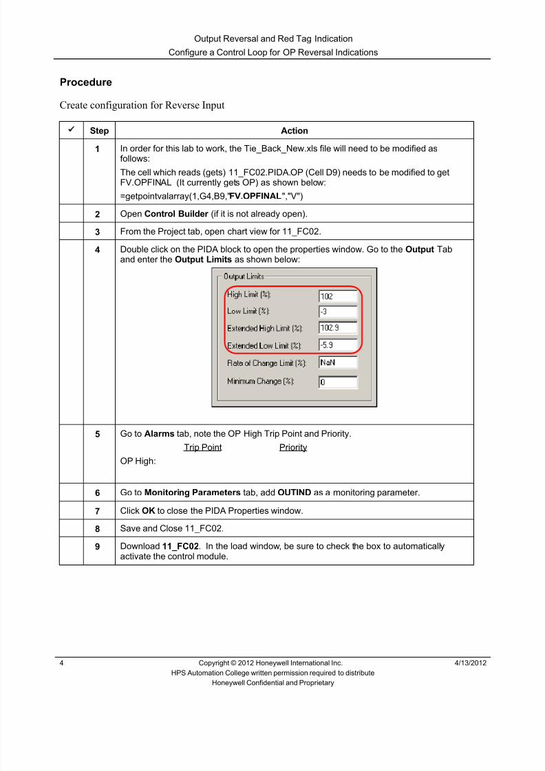
8/9/2019 Student Course Book- Automation
http://slidepdf.com/reader/full/student-course-book-automation 598/1165
Output Reversal and Red Tag Indication
Configure a Control Loop for OP Reversal Indications
4 Copyright © 2012 Honeywell International Inc. 4/13/2012
HPS Automation College written permission required to distributeHoneywell Confidential and Proprietary
Procedure
Create configuration for Reverse Input
Step Action1 In order for this lab to work, the Tie_Back_New.xls file will need to be modified as
follows:
The cell which reads (gets) 11_FC02.PIDA.OP (Cell D9) needs to be modified to getFV.OPFINAL (It currently gets OP) as shown below:
=getpointvalarray(1,G4,B9," FV.OPFINAL ","V")
2 Open Control Builder (if it is not already open).
3 From the Project tab, open chart view for 11_FC02.
4 Double click on the PIDA block to open the properties window. Go to the Output Taband enter the Output Limits as shown below:
5 Go to Alarms tab, note the OP High Trip Point and Priority.
Trip Point Priority
OP High:
6 Go to Monitoring Parameters tab, add OUTIND as a monitoring parameter.
7 Click OK to close the PIDA Properties window.
8 Save and Close 11_FC02.
9 Download 11_FC02 . In the load window, be sure to check the box to automaticallyactivate the control module.

8/9/2019 Student Course Book- Automation
http://slidepdf.com/reader/full/student-course-book-automation 599/1165
Output Reversal and Red Tag Indication
Configure a Control Loop for OP Reversal Indications
4/13/2012 Copyright © 2012 Honeywell International Inc. 5
HPS Automation College written permission required to distributeHoneywell Confidential and Proprietary
Step Action
10 After downloading, click the Monitoring tab and verify that 11_FC02 appears green. Ifyou are using Series C I/O, ensure the I/O channels are also active.
11 Open Station if not already opened. Go to the Detail Display of 11_FC02 .
12 Change the station security level to MNGR.
13 Change the mode to AUTO , and change the SP to 9.3 .

8/9/2019 Student Course Book- Automation
http://slidepdf.com/reader/full/student-course-book-automation 600/1165
Output Reversal and Red Tag Indication
Configure a Control Loop for OP Reversal Indications
6 Copyright © 2012 Honeywell International Inc. 4/13/2012
HPS Automation College written permission required to distributeHoneywell Confidential and Proprietary
Step Action
14 Go to the PV & OP tab and verify that the Output configuration values match the valuesshown here.
15 Go to the Alarms tab and verify that the Trip Point and Priority configuration valuesmatch the values shown here.

8/9/2019 Student Course Book- Automation
http://slidepdf.com/reader/full/student-course-book-automation 601/1165
Output Reversal and Red Tag Indication
Configure a Control Loop for OP Reversal Indications
4/13/2012 Copyright © 2012 Honeywell International Inc. 7
HPS Automation College written permission required to distributeHoneywell Confidential and Proprietary
Step Action
16 Go to the Chart tab. On the PIDA block , double-click on OUTIND and change the valueto REVERSE.
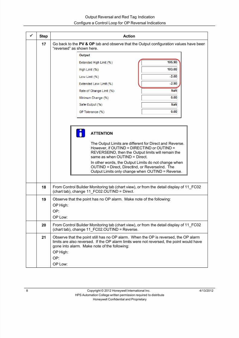
8/9/2019 Student Course Book- Automation
http://slidepdf.com/reader/full/student-course-book-automation 602/1165
Output Reversal and Red Tag Indication
Configure a Control Loop for OP Reversal Indications
8 Copyright © 2012 Honeywell International Inc. 4/13/2012
HPS Automation College written permission required to distributeHoneywell Confidential and Proprietary
Step Action
17 Go back to the PV & OP tab and observe that the Output configuration values have been“reversed” as shown here.
ATTENTION
The Output Limits are different for Direct and Reverse.However, if OUTIND = DIRECTIND or OUTIND =REVERSEIND, then the Output limits will remain thesame as when OUTIND = Direct.In other words, the Output Limits do not change whenOUTIND = Direct, DirectInd, or ReverseInd. TheOutput Limits only change when OUTIND = Reverse.
18 From Control Builder Monitoring tab (chart view), or from the detail display of 11_FC02(chart tab), change 11_FC02.OUTIND = Direct.
19 Observe that the point has no OP alarm. Make note of the following:
OP High:
OP:
OP Low:
20 From Control Builder Monitoring tab (chart view), or from the detail display of 11_FC02(chart tab), change 11_FC02.OUTIND = Reverse.
21 Observe that the point still has no OP alarm. When the OP is reversed, the OP alarmlimits are also reversed. If the OP alarm limits were not reversed, the point would havegone into alarm. Make note of the following:
OP High:
OP:
OP Low:

8/9/2019 Student Course Book- Automation
http://slidepdf.com/reader/full/student-course-book-automation 603/1165
Output Reversal and Red Tag Indication
Configure a Control Loop for OP Reversal Indications
4/13/2012 Copyright © 2012 Honeywell International Inc. 9
HPS Automation College written permission required to distributeHoneywell Confidential and Proprietary
Step Action
22 Change 11_FC02.OUTIND = Direct.
23 With 11_FC02 in Auto, change the SP to 50 to generate an OP High Alarm. Do notacknowledge the alarm, but observe the alarm indication in the Alarm Summary. Makenote of the following:Condition:
Trip Value:
Live Value:
24 Change 11_FC02.OUTIND = Reverse.
25 Observe the change in condition on the Alarm Summary page. Make note of thefollowing for the new alarm:
Condition:
Trip Value:
Live Value:
Also make note of the following for the previous alarm:
Status of the OP High Alarm:
ATTENTION
The OP High Alarm is still shown (because it had not beenacknowledged), but is shown as returned to normal.
An OP Low Alarm is generated with a new Trip Value, and anew Live Value.
26 Acknowledge all alarms.
27 Change the 11_FC02.SP = 30 to remove all alarms.

8/9/2019 Student Course Book- Automation
http://slidepdf.com/reader/full/student-course-book-automation 604/1165
Output Reversal and Red Tag Indication
Configure a Control Loop for OP Reversal Indications
10 Copyright © 2012 Honeywell International Inc. 4/13/2012
HPS Automation College written permission required to distributeHoneywell Confidential and Proprietary
Step Action
28
ATTENTION
The screen captures below are for demonstration only.
Notice the graphical indications on the faceplate when OUTIND = DIRECTIND orOUTIND = REVERSEIND.
29 Change OUTIND back to Direct before starting next lab.
30 In Control Builder, on the Project tab, for 11_F02.PIDA, restore the output limits asshown below:
OPHILM = 105
OPLOLM = -5
OPEXHILM = 106.9
OPEXLOLM= -6.9
31 Save and download 11_FC02 (with activation).
Direct OUTIND
Reverse OUTIND

8/9/2019 Student Course Book- Automation
http://slidepdf.com/reader/full/student-course-book-automation 605/1165
Output Reversal and Red Tag Indication
Configure a Control Loop for Red Tag Indication
4/13/2012 Copyright © 2012 Honeywell International Inc. 11
HPS Automation College written permission required to distributeHoneywell Confidential and Proprietary
Configure a Control Loop for Red Tag Indication
Experion Software Installation Server
The Purpose of this lesson is to see the affects of enabling Red Tag and Operator Tag. After you
complete this lesson you will be able to check:• Red Tag and Operator Tag
Prerequisites
• Experion Server running
• Control Builder database loaded and running
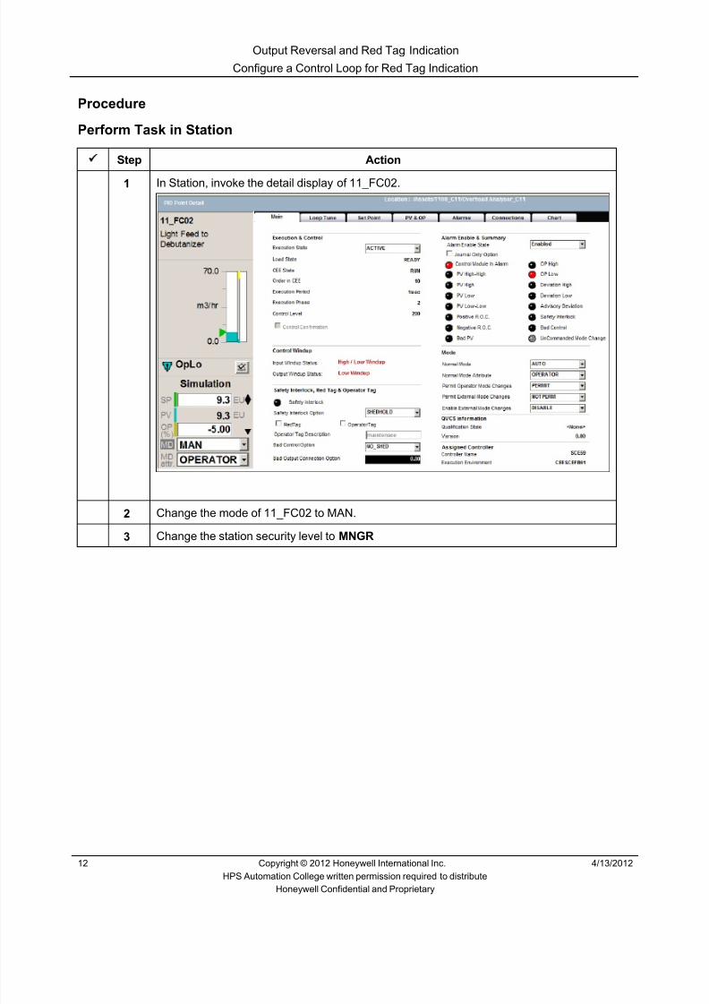
8/9/2019 Student Course Book- Automation
http://slidepdf.com/reader/full/student-course-book-automation 606/1165
Output Reversal and Red Tag Indication
Configure a Control Loop for Red Tag Indication
12 Copyright © 2012 Honeywell International Inc. 4/13/2012
HPS Automation College written permission required to distributeHoneywell Confidential and Proprietary
Procedure
Perform Task in Station
Step Action
1 In Station, invoke the detail display of 11_FC02.
2 Change the mode of 11_FC02 to MAN.
3 Change the station security level to MNGR

8/9/2019 Student Course Book- Automation
http://slidepdf.com/reader/full/student-course-book-automation 607/1165
Output Reversal and Red Tag Indication
Configure a Control Loop for Red Tag Indication
4/13/2012 Copyright © 2012 Honeywell International Inc. 13
HPS Automation College written permission required to distributeHoneywell Confidential and Proprietary
Step Action
4 On the Main tab, check the ‘RedTag’ Checkbox.
ATTENTION
When the RedTag option is enabled, a red color lockwill appear to the right of the OP.

8/9/2019 Student Course Book- Automation
http://slidepdf.com/reader/full/student-course-book-automation 608/1165
Output Reversal and Red Tag Indication
Configure a Control Loop for Red Tag Indication
14 Copyright © 2012 Honeywell International Inc. 4/13/2012
HPS Automation College written permission required to distributeHoneywell Confidential and Proprietary
Step Action
5 Try to change both the Output and the Mode. Observe the information displayed in thetool tip.
ATTENTION
The tool tip indicates that the function block is RedTagged. Therefore, the operator can not makechanges to OP or MODE’
6 Uncheck the ‘RedTag’ Checkbox.

8/9/2019 Student Course Book- Automation
http://slidepdf.com/reader/full/student-course-book-automation 609/1165
Output Reversal and Red Tag Indication
Configure a Control Loop for Red Tag Indication
4/13/2012 Copyright © 2012 Honeywell International Inc. 15
HPS Automation College written permission required to distributeHoneywell Confidential and Proprietary
Step Action
7 Check the ‘ OperatorTag ’ checkbox to enable Operator Tag.
Enter Operator Tag Description as “ Maintenance ” and press Enter.
ATTENTION
The OperatorTag option allows an operator to tag the block for “operatormaintenance” or a similar condition
Enabling the OperatorTag option does not lock the point's OP and MODEparameters

8/9/2019 Student Course Book- Automation
http://slidepdf.com/reader/full/student-course-book-automation 610/1165
Output Reversal and Red Tag Indication
Configure a Control Loop for Red Tag Indication
16 Copyright © 2012 Honeywell International Inc. 4/13/2012
HPS Automation College written permission required to distributeHoneywell Confidential and Proprietary
Step Action
8 When the OperatorTag option is enabled, a flag will appear to the right of the OP.
9 Move the mouse over the flag which is shown to the right of the OP, and read the tool tip.
10 Clear the ‘Operator Tag’ checkbox.

8/9/2019 Student Course Book- Automation
http://slidepdf.com/reader/full/student-course-book-automation 611/1165
1
1
Honeywell ConfidentialCopyright © 2012 Honeywell International Inc.
4/13/2012
Describe Templates and the Substitute NameList
Device Control Module Describe Templates and the Substitute Name ListDevice Control Module Describe Templates and the Substitute Name List
Honeywell
Honeywell ConfidentialCopyright © 2012 Honeywell International Inc.
4/13/20122
Big Picture – Device Control Point
State State Name DI
State 1 START 1
State 0 STOP 0
DI DO
State State Name DO
State 1 START 1
State 0 STOP 0
Input Truth Table and State Names Output Truth Table and State Names
Device Control Module Describe Templates and the Substitute Name List

8/9/2019 Student Course Book- Automation
http://slidepdf.com/reader/full/student-course-book-automation 612/1165
2
Honeywell
Honeywell ConfidentialCopyright © 2012 Honeywell International Inc.
4/13/20123
Some Device Control Block Configuration
• See Appendix (last book) for more details
• Up to 3 States• Up to 4 Inputs• Up to 3 Outputs
Device Control Module Describe Templates and the Substitute Name List
Honeywell
Honeywell ConfidentialCopyright © 2012 Honeywell International Inc.
4/13/20124
Simple Device Control Block with One Input, One Output
Device Control Module Describe Templates and the Substitute Name List

8/9/2019 Student Course Book- Automation
http://slidepdf.com/reader/full/student-course-book-automation 613/1165
3
Honeywell
Honeywell ConfidentialCopyright © 2012 Honeywell International Inc.
4/13/20125
Device Control with Permissives and Interlocks
• Interlock Strategies are implemented using Permissives, Override Interlocks,and the Safety Interlock
• Permissive P(0-2) – There is a Permissive for each state – Normally ON – Operator can select the state if it’s
Permissive is asserted (ON) – Can be Bypassed
• Override Interlock OI(0-2) – There is an Override Interlock for each state – Normally OFF – When an Override Interlock is asserted (ON)
the Output is forced to it’s state – Can be Bypassed
• Safety Interlock SI – Normally OFF – Sets the Output to the Safe State when asserted (ON) – Cannot be Bypassed
P 0)
P 1)
OI 1)
OI 0)
SI
ON
ON
OFF
OFF
OFF
Device Control Module Describe Templates and the Substitute Name List
Honeywell
Honeywell ConfidentialCopyright © 2012 Honeywell International Inc.
4/13/20126
Device Control Block with Logic
Device Control Module Describe Templates and the Substitute Name List

8/9/2019 Student Course Book- Automation
http://slidepdf.com/reader/full/student-course-book-automation 614/1165
4
Honeywell
Honeywell ConfidentialCopyright © 2012 Honeywell International Inc.
4/13/20127
Project Parameters and Add Block Pins
• Project Parameters – Select parameters of each block which will be available outside of the
template (ex: FAN_LOGIC.GEA.IN[2] ) – Give each projected parameter a name (ex: Temp_Num)
• This will be accessed by FAN_LOGIC.Temp_Num
• Add Block Pins for theprojected parameters
FAN_LOGIC
Temp_Num
Device Control Module Describe Templates and the Substitute Name List
Honeywell
Honeywell ConfidentialCopyright © 2012 Honeywell International Inc.
4/13/20128
Instantiate the Template (Create Instances)
FAN_LOGIC
HS_A
HS_B
HS_H
Device Control Module Describe Templates and the Substitute Name List

8/9/2019 Student Course Book- Automation
http://slidepdf.com/reader/full/student-course-book-automation 615/1165
5
Honeywell
Honeywell ConfidentialCopyright © 2012 Honeywell International Inc.
4/13/20129
Control Module with Template Added
Instance of the template
HS_A
Device Control Module Describe Templates and the Substitute Name List
Honeywell
Honeywell ConfidentialCopyright © 2012 Honeywell International Inc.
4/13/201210
Introduction
• In this lesson you will learn how to usetemplates and the substitute name listto streamline the production of controlmodules.
• At the conclusion of this lesson, youwill know how to:
– Build control modules using templates
– Load and verify templates
– Build control modules using the
substitute name list
Device Control Module Describe Templates and the Substitute Name List

8/9/2019 Student Course Book- Automation
http://slidepdf.com/reader/full/student-course-book-automation 616/1165
6
Honeywell
Honeywell ConfidentialCopyright © 2012 Honeywell International Inc.
4/13/201211
Topics
• Building Control Modules Using Templates
• Loading and Verifying a Template
• Building Control Modules Using a Substitute Name List
Device Control Module Describe Templates and the Substitute Name List
Honeywell
Honeywell ConfidentialCopyright © 2012 Honeywell International Inc.
4/13/201212
Introduction
• Templates are control modules created in Control Builder
• Once created, templates may be used to build multiple copies of desiredcontrol strategies
• Templates allow for change to propagate from parent to child
• Templates can contain other templates, up to five levels
IN[2]
GEA
Template
Temp_Num
Device Control Module Describe Templates and the Substitute Name List
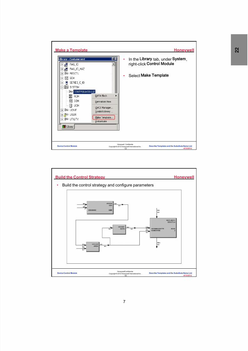
8/9/2019 Student Course Book- Automation
http://slidepdf.com/reader/full/student-course-book-automation 617/1165
7
Honeywell
Honeywell ConfidentialCopyright © 2012 Honeywell International Inc.
4/13/201213
Make a Template
• In the Library tab, under System ,right-click Control Module
• Select Make Template
Device Control Module Describe Templates and the Substitute Name List
Honeywell
Honeywell ConfidentialCopyright © 2012 Honeywell International Inc.
4/13/201214
Build the Control Strategy
• Build the control strategy and configure parameters
Device Control Module Describe Templates and the Substitute Name List

8/9/2019 Student Course Book- Automation
http://slidepdf.com/reader/full/student-course-book-automation 618/1165
8
Honeywell
Honeywell ConfidentialCopyright © 2012 Honeywell International Inc.
4/13/201215
IN[2]
GEA
Template
Temp_Num
Identify Projected Parameters
• Define custom parameters for your control module
• Connect your custom parameters to exposed pins
Device Control Module Describe Templates and the Substitute Name List
Honeywell
Honeywell ConfidentialCopyright © 2012 Honeywell International Inc.
4/13/201216
Add Block Pins For Projected Parameters
• Add a block pin for eachprojected parameter which willbe wired
IN[2]
GEA
TemplateTemp_Num
Device Control Module Describe Templates and the Substitute Name List

8/9/2019 Student Course Book- Automation
http://slidepdf.com/reader/full/student-course-book-automation 619/1165
9
Honeywell
Honeywell ConfidentialCopyright © 2012 Honeywell International Inc.
4/13/201217
Use Template
• Instantiate makes a useable version of the template for project
• Make Template makes a new template in the library (child of theoriginal)
The name this templatewill have in project
Device Control Module Describe Templates and the Substitute Name List
Honeywell
Honeywell ConfidentialCopyright © 2012 Honeywell International Inc.
4/13/201218
Insert a Template
Insert the template into a CM
Device Control Module Describe Templates and the Substitute Name List

8/9/2019 Student Course Book- Automation
http://slidepdf.com/reader/full/student-course-book-automation 620/1165
10
Honeywell
Honeywell ConfidentialCopyright © 2012 Honeywell International Inc.
4/13/201219
Complete CM with Template
• Complete the CM with a template
Template
Device Control Module Describe Templates and the Substitute Name List
Honeywell
Honeywell ConfidentialCopyright © 2012 Honeywell International Inc.
4/13/201220
Question 1: Template Use
Incorrect. Templates are best used where a complex controlstrategy is used in multiple control modules.
Click anywhere to continue.
Incorrect. Templates are best used where a complex controlstrategy is used in multiple control modules.
Click anywhere to continue.
Correct! Templates are best used where a complex controlstrategy is used in multiple control modules.
Click anywhere to continue.
Incorrect. Templates are best used where a complex controlstrategy is used in multiple control modules.
Click anywhere to continue.
Correct - Click anywhere to continueIncorrect - Click anywhere to continueYou answered this correctly!
Your answer:The correct answer is:
You did not answer this question completelyYou must answer the question beforecontinuing
Submit Clear
Templates are best used:
IN[2]
GEA
Template
Temp_Num
A) For control modules containing one function block
B) For complex graphics
C) Where a complex control strategy is used in multiplecontrol modules
D) As a tool to prioritize the alarm sequence
Device Control Module Describe Templates and the Substitute Name List
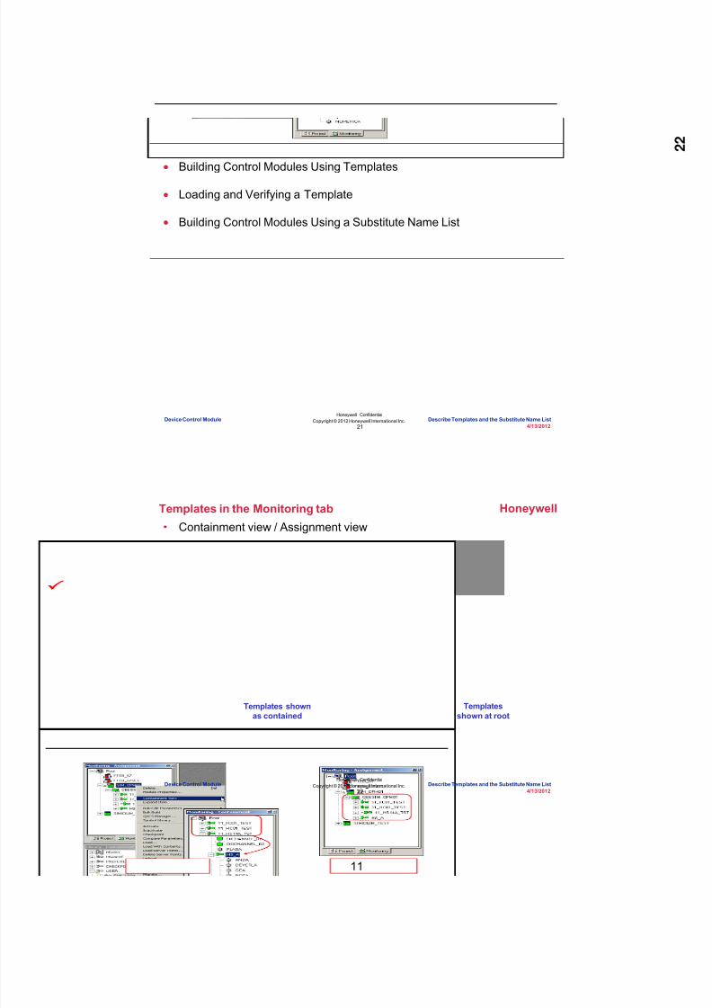
8/9/2019 Student Course Book- Automation
http://slidepdf.com/reader/full/student-course-book-automation 621/1165
11
Honeywell
Honeywell ConfidentialCopyright © 2012 Honeywell International Inc.
4/13/201221
Topics
• Building Control Modules Using Templates
• Loading and Verifying a Template
• Building Control Modules Using a Substitute Name List
Device Control Module Describe Templates and the Substitute Name List
Honeywell
Honeywell ConfidentialCopyright © 2012 Honeywell International Inc.
4/13/201222
Templates in the Monitoring tab
• Containment view / Assignment view
Templatesshown at root
Templates shownas contained
Device Control Module Describe Templates and the Substitute Name List

8/9/2019 Student Course Book- Automation
http://slidepdf.com/reader/full/student-course-book-automation 622/1165
12
Honeywell
Honeywell ConfidentialCopyright © 2012 Honeywell International Inc.
4/13/201223
Chart View of a CM with a Template
Green indicates that the template is active
Blue indicates that the template is inactive
Red indicates that the template has failed
Device Control Module Describe Templates and the Substitute Name List
Honeywell
Honeywell ConfidentialCopyright © 2012 Honeywell International Inc.
4/13/201224
Template in Chart View
Double-click the template in the
Monitoring Tab
Device Control Module Describe Templates and the Substitute Name List

8/9/2019 Student Course Book- Automation
http://slidepdf.com/reader/full/student-course-book-automation 623/1165
13
Honeywell
Honeywell ConfidentialCopyright © 2012 Honeywell International Inc.
4/13/201225
Question 2: Loading and Verifying Templates
Correct - Click anywhere to continueIncorrect - Click anywhere to continueYou answered this correctly!Your answer:The correct answer is:You did not answer this question completelyYou must answer the question before
continuing
Submit Clear
Correct! A blue border on the bottom and the right hand
side of an instance of a template in the Control Builderchart view tells you that the instance is inactive and notactive.
Click anywhere to continue.
Incorrect. A blue border on the bottom and the right
hand side of an instance of a template in the ControlBuilder chart view tells you that the instance is inactiveand not active.
Click anywhere to continue.
Incorrect. A blue border on the bottom and the right
hand side of an instance of a template in the ControlBuilder chart view tells you that the instance is inactiveand not active.
Click anywhere to continue.
Incorrect. A blue border on the bottom and the right
hand side of an instance of a template in the ControlBuilder chart view tells you that the instance is inactiveand not active.
Click anywhere to continue.
Which statement about templates is false?
A) A blue border on the bottom and right hand side of an instance of a template in the Control Builder chartview tells you the instance is active
B) In Control Builder containment view, a templateappears as a function block in the control module
C) In the Control Builder assignment view, a templateappears as a control module in the CEE simulation
D) None of the above
Device Control Module Describe Templates and the Substitute Name List
Honeywell
Honeywell ConfidentialCopyright © 2012 Honeywell International Inc.
4/13/201226
Topics
• Building Control Modules Using Templates
• Loading and Verifying a Template
• Building Control Modules Using a Substitute Name List
Device Control Module Describe Templates and the Substitute Name List

8/9/2019 Student Course Book- Automation
http://slidepdf.com/reader/full/student-course-book-automation 624/1165
14
Honeywell
Honeywell ConfidentialCopyright © 2012 Honeywell International Inc.
4/13/201227
Build Templates using Substitute Name List
Create the substitute names
Connect them to function block types
Device Control Module Describe Templates and the Substitute Name List
Honeywell
Honeywell ConfidentialCopyright © 2012 Honeywell International Inc.
4/13/201228
Build Templates using Substitute Name List
Use the parameter connection tool
Select the substitute name as a connection
Device Control Module Describe Templates and the Substitute Name List

8/9/2019 Student Course Book- Automation
http://slidepdf.com/reader/full/student-course-book-automation 625/1165
15
Honeywell
Honeywell ConfidentialCopyright © 2012 Honeywell International Inc.
4/13/201229
Build Templates using Substitute Name List
• The substituted names can be resolved to a function block parameterwhen the template is instantiated.
Resolved
Device Control Module Describe Templates and the Substitute Name List
Honeywell
Honeywell ConfidentialCopyright © 2012 Honeywell International Inc.
4/13/201230
Question 3: Substitute Name List
No. The correct answer is "All of the above". You may
create templates to be instantiated as stand -alonecontrol modules or embedded control modules using
projected parameters.
Click anywhere to continue.
No. The correct answer is "All of the above". You may
create templates to be instantiated as stand -alonecontrol modules or embedded control modules using
projected parameters.
Click anywhere to continue.
Yes! The correct answer is "All of the above". You may
create templates to be instantiated as stand -alonecontrol modules or embedded control modules using
projected parameters.
Click anywhere to continue.
Correct - Click anywhere to continueIncorrect - Click anywhere to continueYou answered this correctly!Your answer:
The correct answer is:
You did not answer this question completelyYou must answer the question beforecontinuing
Submit Clear
You may create templates to be: A) Instantiated as stand-alone
control modules using yoursubstitute name list
B) Embedded control modulesusing projected parameters andblock pins
C) All of the above
Device Control Module Describe Templates and the Substitute Name List

8/9/2019 Student Course Book- Automation
http://slidepdf.com/reader/full/student-course-book-automation 626/1165
16
Honeywell
Honeywell ConfidentialCopyright © 2012 Honeywell International Inc.
4/13/201231
Summary
• When using templates, remember:
– Templates are built in Control Builder.
– Once created, templates may be used to build multiple copies of desiredcontrol strategies.
– Templates allow for change to propagate from parent to child.
– You may create templates to be instantiated as stand-alone control modulesusing your substitute name list or embedded control modules usingprojected parameters and block pins.
Device Control Module Describe Templates and the Substitute Name List
Honeywell
Honeywell ConfidentialCopyright © 2012 Honeywell International Inc.
4/13/201232
Conclusion
Describe Templates and the Substitute Name List
CompletionCertificate
Proceed to the Configure a Device Control Module – with Logic andConfigure a Device Control Module – with Interlock lab exercises
Device Control Module Describe Templates and the Substitute Name List

8/9/2019 Student Course Book- Automation
http://slidepdf.com/reader/full/student-course-book-automation 627/1165
4/13/2012 Copyright © 2012 Honeywell International Inc. 1
HPS Automation College written permission required to distributeHoneywell Confidential and Proprietary
Topic: Device Control Module
Contents
Configure a Device Control Module - with Logic ................................ ................................................... 3
Configure a Device Control Module - with Interlock ............................................................................ 39

8/9/2019 Student Course Book- Automation
http://slidepdf.com/reader/full/student-course-book-automation 628/1165
2 Copyright © 2012 Honeywell International Inc. 4/13/2012
HPS Automation College written permission required to distributeHoneywell Confidential and Proprietary
This page was intentionally left blank.

8/9/2019 Student Course Book- Automation
http://slidepdf.com/reader/full/student-course-book-automation 629/1165
Device Control Module
Configure a Device Control Module - with Logic
4/13/2012 Copyright © 2012 Honeywell International Inc. 3
HPS Automation College written permission required to distributeHoneywell Confidential and Proprietary
Configure a Device Control Module - with Logic
Objective
• Configure a Device Control Module for Fans on the Heat Exchanger E-110 of theDebutanizer Model
• Configure basic Logic Blocks: NOT, AND, GE (Greater than or equal to)
Prerequisites
• Experion PKS Server or a client machine with Experion PKS Engineering Tools loaded
• Debutanizer graphic (debutanizer_123.htm) loaded on the Server. (This is required at a latertime to check the control strategy built in this lab.)
• Control Builder running with one or two Project/Monitor tree windows open
• SCE Controller and IOMs configured
• Configure Data Acquisition Control Module and configure PID Control Module labs arecompleted

8/9/2019 Student Course Book- Automation
http://slidepdf.com/reader/full/student-course-book-automation 630/1165
Device Control Module
Configure a Device Control Module - with Logic
4 Copyright © 2012 Honeywell International Inc. 4/13/2012
HPS Automation College written permission required to distributeHoneywell Confidential and Proprietary
Introduction
The control logic for switching the fans on Condenser E-110 is developed in this lab.
Operationally, the cooling fans are turned on in case the top temperature of 11_TI25 is greater thana specified value. The Operator initiates the start command and each additional fan starts as thetemperature increases. When the temperature reaches 260 Deg C then 11_TI25 resets and the fansturn OFF automatically.
• The module will be built, loaded and tested
• The implementation is as follows:
The DEVCTL (Device Control) block is a multi-input, multi-output function that provides aninterface to discrete devices such as motors, solenoid valves, and motor-operated valves. This block
provides built-in structures for handling interlocks and supports the display of interlock conditionsin group, detail, and graphic displays.
In this lab, Device Control points are used to control the cooling fans of the heat exchangerE-110. When the temperature of T-100 overhead (11_TI25) goes above 55 Deg C, then FAN A (11_HS14A) is started.
Similarly, FAN B (11_HS14B) is started only if the temperature goes above 60 Deg C and the otherfans are started sequentially according to the temperature of the tower top (11_TI25).

8/9/2019 Student Course Book- Automation
http://slidepdf.com/reader/full/student-course-book-automation 631/1165
Device Control Module
Configure a Device Control Module - with Logic
4/13/2012 Copyright © 2012 Honeywell International Inc. 5
HPS Automation College written permission required to distributeHoneywell Confidential and Proprietary
Procedure
Create a Template
Step Action1 Launch Control Builder from Configuration Studio, if not already open.
2 Create a Template .• Click the “ +” icon adjacent to System in the library• Right click CONTROLMODULE • Select Make Template

8/9/2019 Student Course Book- Automation
http://slidepdf.com/reader/full/student-course-book-automation 632/1165
Device Control Module
Configure a Device Control Module - with Logic
6 Copyright © 2012 Honeywell International Inc. 4/13/2012
HPS Automation College written permission required to distributeHoneywell Confidential and Proprietary
Step Action
3 Configure CM Parameters.
Double-click the blank space in the chart view of the new Template form.
Enter FAN_LOGIC in the Name field.
Enter FAN_LOGIC_ITEM in the Item Name field.
Enter FAN TEMP CONTROL in the Description field.
Enter FANS_C11 in the Parent Asset field (use browser to select parent asset).
Accept the defaults for any remaining parameters on this tab.

8/9/2019 Student Course Book- Automation
http://slidepdf.com/reader/full/student-course-book-automation 633/1165
Device Control Module
Configure a Device Control Module - with Logic
4/13/2012 Copyright © 2012 Honeywell International Inc. 7
HPS Automation College written permission required to distributeHoneywell Confidential and Proprietary
Step Action
4 Click the Server Displays tab.
Enter the following display details:
Point Detail Display: sysDtldevctlA
ATTENTION
The Group Detail Display will be selected based on thetype of Point Detail Display specified.These are the standard Honeywell Device ControlPoint Detail and Group Detail Displays.
5 Click OK .

8/9/2019 Student Course Book- Automation
http://slidepdf.com/reader/full/student-course-book-automation 634/1165
Device Control Module
Configure a Device Control Module - with Logic
8 Copyright © 2012 Honeywell International Inc. 4/13/2012
HPS Automation College written permission required to distributeHoneywell Confidential and Proprietary
Adding Function Blocks to a Template
Step Action
1 In the chart view of FAN_LOGIC, add Function Blocks from the respective Libraryfamilies, according to the sequence below and the diagram displayed in step 2.
Block Family Block
LOGIC GE (A)
LOGIC NOT (B)
LOGIC AND (C)
DEVCTL DEVCTL (D)
ATTENTION
When the blocks are inserted according to the abovesequence, each one is assigned an execution order(ORDERINCM) automatically, increasing in multiplesof 10. ORDERINCM determines the relative executionorder of blocks within the CM in ascending order. Thisparameter can be changed as required. This field canaccept any number from 0 to 65535.

8/9/2019 Student Course Book- Automation
http://slidepdf.com/reader/full/student-course-book-automation 635/1165
Device Control Module
Configure a Device Control Module - with Logic
4/13/2012 Copyright © 2012 Honeywell International Inc. 9
HPS Automation College written permission required to distributeHoneywell Confidential and Proprietary
Step Action
2 After adding all the blocks, arrange them as shown.
The explanation of each block is given below.
(A) GEA:This block compares the Value in a Numeric Block (NUMERICA, added later) with theactual temperature (PV of) 11_TI25.
(C) ANDA:
This block is a gate that provides the Start command to FANA if:
1. The temperature is greater than 55 Deg C and
2. The Operator has entered the start command.
(B) NOTA:
This block is a gate that inverts the signal from the ANDA gate and sends the signal tothe input OI(0) of the DEVCTLA block. This is the stop command for FAN A.
(D) DEVCTLA:
This block is the Device Control Block that provides the operator interface to the digitalI/Os.
A
B
C
D

8/9/2019 Student Course Book- Automation
http://slidepdf.com/reader/full/student-course-book-automation 636/1165
Device Control Module
Configure a Device Control Module - with Logic
10 Copyright © 2012 Honeywell International Inc. 4/13/2012
HPS Automation College written permission required to distributeHoneywell Confidential and Proprietary
Step Action
3 Configure the Device Control Block .
Double click the Device Control Block ( DEVCTLA .)
Enter the following details in the Main tab:
Name: DEVCTLA
Description: Fan A Start in E-110
4 Enter the Block Sizing parameters in the Main tab as follows:
Number Of Inputs: 1
Number Of Outputs: 1
Number Of States: 2
Enter the State Names as follows:
State 1 Name: START
State 0 Name: STOP
Accept the defaults for any remaining parameters on this tab.

8/9/2019 Student Course Book- Automation
http://slidepdf.com/reader/full/student-course-book-automation 637/1165
Device Control Module
Configure a Device Control Module - with Logic
4/13/2012 Copyright © 2012 Honeywell International Inc. 11
HPS Automation College written permission required to distributeHoneywell Confidential and Proprietary
Step Action
5 On the Inputs tab, enter following details:
Number of Digital Inputs: 1 (default)
Input 1 unchecked Box : STOP
Input 1 checked Box: START • A selected checkbox means Input 1 is in an ON condition• Input 1 is the feedback from the field device (FANA)• The above entries (illustrated below) indicate that when the device is in the Start
State, Input 1 is ON• When the Device is in the Stop State, Input 1 is OFF
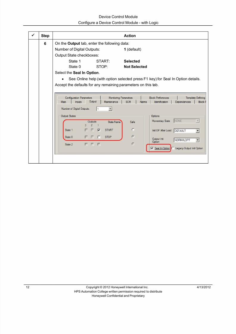
8/9/2019 Student Course Book- Automation
http://slidepdf.com/reader/full/student-course-book-automation 638/1165
Device Control Module
Configure a Device Control Module - with Logic
12 Copyright © 2012 Honeywell International Inc. 4/13/2012
HPS Automation College written permission required to distributeHoneywell Confidential and Proprietary
Step Action
6 On the Output tab, enter the following data:
Number of Digital Outputs: 1 (default)
Output State checkboxes:
State 1 START: Selected State 0 STOP: Not Selected
Select the Seal In Option .• See Online help (with option selected press F1 key) for Seal In Option details.
Accept the defaults for any remaining parameters on this tab.

8/9/2019 Student Course Book- Automation
http://slidepdf.com/reader/full/student-course-book-automation 639/1165
Device Control Module
Configure a Device Control Module - with Logic
4/13/2012 Copyright © 2012 Honeywell International Inc. 13
HPS Automation College written permission required to distributeHoneywell Confidential and Proprietary
Step Action
7 On the Alarms tab, enter following data:
Time toSTOP
Time toSTART
Priority Severity
Command Disagree 10 10 LOW 0
Command Fail 5 5 HIGH 0

8/9/2019 Student Course Book- Automation
http://slidepdf.com/reader/full/student-course-book-automation 640/1165
Device Control Module
Configure a Device Control Module - with Logic
14 Copyright © 2012 Honeywell International Inc. 4/13/2012
HPS Automation College written permission required to distributeHoneywell Confidential and Proprietary
Step Action
8 On the Block Pins tab:
Remove the SI pin.• Select SI in the Selected Parameters Table, click the Remove button
Add pins OI[0] and OI[1] as inputs on the left.• Select Input and Left / Right • Click the Add button
Click OK .
9 Connect 11_TI25.DACA.PV to the IN[1] pin of the GEA block with a parameter
connector, as shown below.

8/9/2019 Student Course Book- Automation
http://slidepdf.com/reader/full/student-course-book-automation 641/1165
Device Control Module
Configure a Device Control Module - with Logic
4/13/2012 Copyright © 2012 Honeywell International Inc. 15
HPS Automation College written permission required to distributeHoneywell Confidential and Proprietary
Step Action
10 Arrange the Blocks and connect them as shown below.
ATTENTION
Change the pin positions as shown in the above figure using theBlock Pins tabs of each function block configuration form.
11 Save FAN_LOGIC.
12 Open the properties of FAN_LOGIC by double-clicking the blank space of the chart.
Select the Projected Parameters tab.
In the first Parameter Name location type Temp_Num .
In the Origin column, click the point selection ( …) buton and in the Point Selectiondialog, select FAN_LOGIC.GEA.IN[2] .
Click Insert Row to add a new row.

8/9/2019 Student Course Book- Automation
http://slidepdf.com/reader/full/student-course-book-automation 642/1165
Device Control Module
Configure a Device Control Module - with Logic
16 Copyright © 2012 Honeywell International Inc. 4/13/2012
HPS Automation College written permission required to distributeHoneywell Confidential and Proprietary
Step Action
13 Using the procedure in the previous step, insert new rows and complete connections asindicated in the table below:
Parameter Name Origin
Fan_Switch FAN_LOGIC.ANDA.IN[2]
D_In FAN_LOGIC.DEVCTLA.DI[1]
D_Out FAN_LOGIC.DEVCTLA.DO[1]
14 Add pins and configure the Block Pins as shown below:
15 Click OK to close the parameters of Fan_Logic.
16 Save and Close FAN_LOGIC.

8/9/2019 Student Course Book- Automation
http://slidepdf.com/reader/full/student-course-book-automation 643/1165
Device Control Module
Configure a Device Control Module - with Logic
4/13/2012 Copyright © 2012 Honeywell International Inc. 17
HPS Automation College written permission required to distributeHoneywell Confidential and Proprietary
Create a Device Control Module
Step Action
1 Create new Control Module and configure CM parametersCreate a new Control Module.
Double-click the blank space in the chart view
Enter the following details
Name: 11_HS14A
Item Name: 11_HS14A_item
Description E-110A FAN
Parent Asset FANS_C11
Accept the defaults for any remaining parameters.
2 Click OK to close the properties of the new Control Module.
3 Save the CM and close the chart window.
4 Assign the CM 11_HS14A to your CEE (CEESCEFB61 or SIM_CEEC300).

8/9/2019 Student Course Book- Automation
http://slidepdf.com/reader/full/student-course-book-automation 644/1165
Device Control Module
Configure a Device Control Module - with Logic
18 Copyright © 2012 Honeywell International Inc. 4/13/2012
HPS Automation College written permission required to distributeHoneywell Confidential and Proprietary
Step Action
5 Open CM 11_HS14A in chart view and add the function blocks from the respectivelibrary families, according to the table below:
Block Family Block Sequence
C200E:
IOCHANNEL
C300:
SERIES_C_IO DI-HV
DICHANNEL (A)
UTILITY NUMERIC (B)
UTILITY FLAG (C)
C200E:
IOCHANNEL
C300:SERIES_C_IO DO-24B
DOCHANNEL (D)

8/9/2019 Student Course Book- Automation
http://slidepdf.com/reader/full/student-course-book-automation 645/1165
Device Control Module
Configure a Device Control Module - with Logic
4/13/2012 Copyright © 2012 Honeywell International Inc. 19
HPS Automation College written permission required to distributeHoneywell Confidential and Proprietary
Step Action
6 After adding the blocks, arrange them as shown.
ATTENTION
The DI and DO channel in the screen capture mightlook different if you are using Series C I/O
A
B
C
D

8/9/2019 Student Course Book- Automation
http://slidepdf.com/reader/full/student-course-book-automation 646/1165

8/9/2019 Student Course Book- Automation
http://slidepdf.com/reader/full/student-course-book-automation 647/1165
Device Control Module
Configure a Device Control Module - with Logic
4/13/2012 Copyright © 2012 Honeywell International Inc. 21
HPS Automation College written permission required to distributeHoneywell Confidential and Proprietary
Step Action
11 Drag HS_A from the project tab into the 11_HS14A chart.

8/9/2019 Student Course Book- Automation
http://slidepdf.com/reader/full/student-course-book-automation 648/1165
Device Control Module
Configure a Device Control Module - with Logic
22 Copyright © 2012 Honeywell International Inc. 4/13/2012
HPS Automation College written permission required to distributeHoneywell Confidential and Proprietary
Step Action
12 Double-click the DICHANNEL to open the DI parameter configuration form.
Enter the following data:
Channel Name HI (the letter I)
13 Refer to the appropriate (C200E or C300) table at the end of Appendix to determine thecorrect module and channel for 11_HS14A.HI.
For C200E: Assign 11_HS14A.HI to the appropriate module and channel.Close the properties of the HI block.
For C300:Close the properties of the HI block.
Assign 11_HS14A.HI to the appropriate module and channel.
14 Double-click the DOCHANNEL to open the DO parameter configuration form.
Enter the following data:
Channel Name: HS
15 Refer to the appropriate (C200E or C300) table at the end of Appendix to determine thecorrect module and channel for 11_HS14A.HS.
For C200E: Assign 11_HS14A.HS to the appropriate module and channel.Close the properties of the HS block.
For C300:Close the properties of the HS block.
Assign 11_HS14A.HS to the appropriate module and channel.

8/9/2019 Student Course Book- Automation
http://slidepdf.com/reader/full/student-course-book-automation 649/1165
Device Control Module
Configure a Device Control Module - with Logic
4/13/2012 Copyright © 2012 Honeywell International Inc. 23
HPS Automation College written permission required to distributeHoneywell Confidential and Proprietary
Step Action
16 Double-click the NUMERICA block.
Enter the following:
Name: NUMERICA
PV High Limit: 95
PV Low Limit: 45
Actual Value: 55
Accept the defaults for any remaining parameters.
Click OK .
17 Double-click the FLAGA block.
Enter the following details:
Name: FLAGA
Description: Operator cmd to turn ON/OFF Fan
Accept the default for any remaining parameters.
Click OK .

8/9/2019 Student Course Book- Automation
http://slidepdf.com/reader/full/student-course-book-automation 650/1165
Device Control Module
Configure a Device Control Module - with Logic
24 Copyright © 2012 Honeywell International Inc. 4/13/2012
HPS Automation College written permission required to distributeHoneywell Confidential and Proprietary
Step Action
18 Arrange and wire the blocks as shown below.
Change block pin locations, as necessary.
Save and Close 11_HS14A.
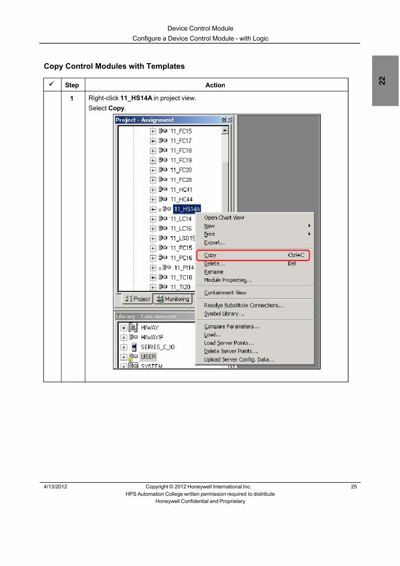
8/9/2019 Student Course Book- Automation
http://slidepdf.com/reader/full/student-course-book-automation 651/1165
Device Control Module
Configure a Device Control Module - with Logic
4/13/2012 Copyright © 2012 Honeywell International Inc. 25
HPS Automation College written permission required to distributeHoneywell Confidential and Proprietary
Copy Control Modules with Templates
Step Action
1 Right-click 11_HS14A in project view.Select Copy .
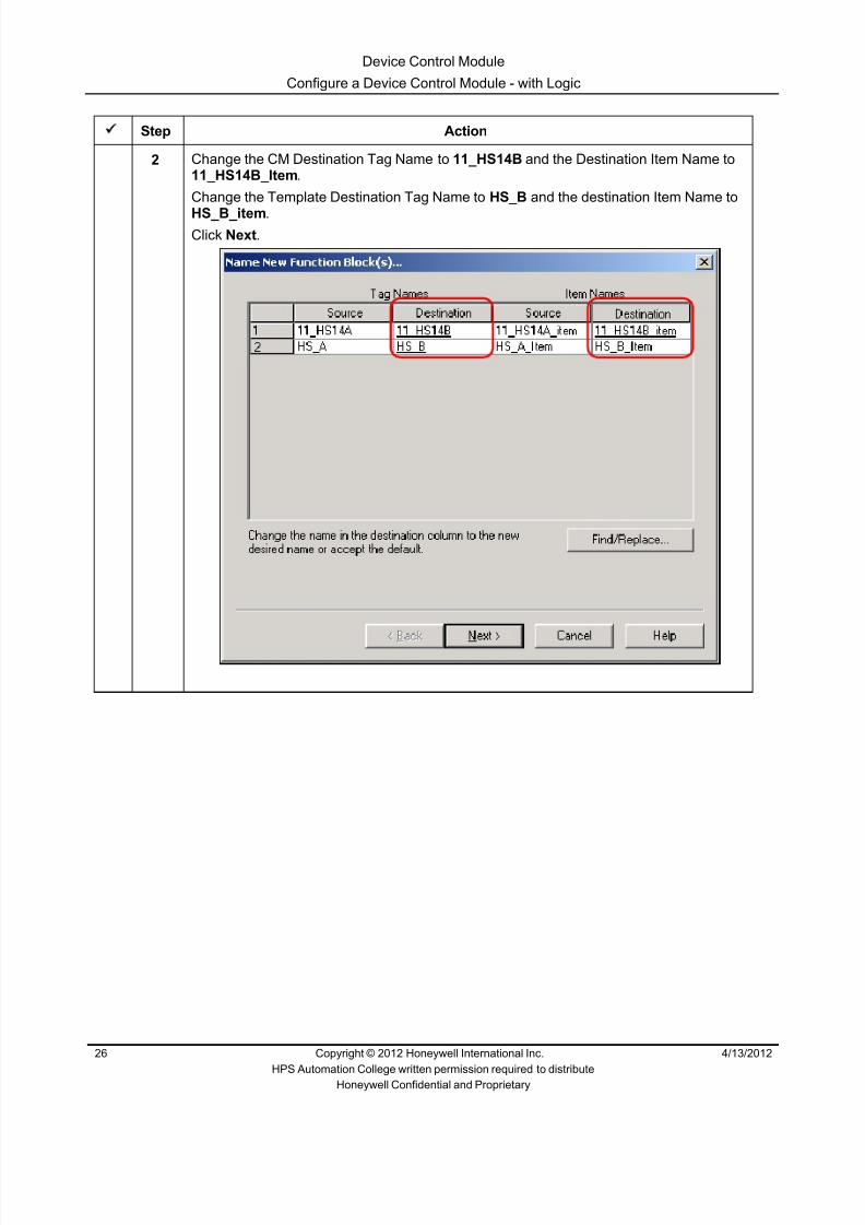
8/9/2019 Student Course Book- Automation
http://slidepdf.com/reader/full/student-course-book-automation 652/1165
Device Control Module
Configure a Device Control Module - with Logic
26 Copyright © 2012 Honeywell International Inc. 4/13/2012
HPS Automation College written permission required to distributeHoneywell Confidential and Proprietary
Step Action
2 Change the CM Destination Tag Name to 11_HS14B and the Destination Item Name to11_HS14B_Item .
Change the Template Destination Tag Name to HS_B and the destination Item Name to
HS_B_item .Click Next .

8/9/2019 Student Course Book- Automation
http://slidepdf.com/reader/full/student-course-book-automation 653/1165
Device Control Module
Configure a Device Control Module - with Logic
4/13/2012 Copyright © 2012 Honeywell International Inc. 27
HPS Automation College written permission required to distributeHoneywell Confidential and Proprietary
Step Action
3
ATTENTION
This step is necessary only for C200E.
Click Next .

8/9/2019 Student Course Book- Automation
http://slidepdf.com/reader/full/student-course-book-automation 654/1165

8/9/2019 Student Course Book- Automation
http://slidepdf.com/reader/full/student-course-book-automation 655/1165
Device Control Module
Configure a Device Control Module - with Logic
4/13/2012 Copyright © 2012 Honeywell International Inc. 29
HPS Automation College written permission required to distributeHoneywell Confidential and Proprietary
Step Action
5 Select 11_HS14B and HS_B in the Unassigned section of Project Tree and Assign bothtags to your CEE (CEESCEFB61 or SIM_CEEC300).
6 Double-click and open 11_HS14B in chart view.
7 Refer to the appropriate (C200E or C300) table at the end of Appendix to determine thecorrect module and channel for 11_HS14B.HI.
For C200E:Display the properties of the HI block (double click on it).
Assign 11_HS14B.HI to the appropriate module and channel.Close the properties of the HI block.
For C300: Assign 11_HS14B.HI to the appropriate module and channel.

8/9/2019 Student Course Book- Automation
http://slidepdf.com/reader/full/student-course-book-automation 656/1165
Device Control Module
Configure a Device Control Module - with Logic
30 Copyright © 2012 Honeywell International Inc. 4/13/2012
HPS Automation College written permission required to distributeHoneywell Confidential and Proprietary
Step Action
8 Refer to the appropriate (C200E or C300) table at the end of Appendix to determine thecorrect module and channel for 11_HS14B.HS.
For C200E:Display the properties of the HS block (double click on it).
Assign 11_HS14B.HS to the appropriate module and channel.Close the properties of the HS block.
For C300: Assign 11_HS14B.HS to the appropriate module and channel.
9 Double-click NUMERICA to open the parameter configuration form.
Ensure the following values are specified:
PV High Limit: 95 PV Low Limit: 45
Actual Value: 60 (note: this is 5 more than the actual value for 11_HS14A)
Accept the defaults for any remaining parameters.
Click OK
10 Save and Close the Chart view.

8/9/2019 Student Course Book- Automation
http://slidepdf.com/reader/full/student-course-book-automation 657/1165
Device Control Module
Configure a Device Control Module - with Logic
4/13/2012 Copyright © 2012 Honeywell International Inc. 31
HPS Automation College written permission required to distributeHoneywell Confidential and Proprietary
Step Action
11 Build six more CMs 11_HS14C through 11_HS14H. Following the same procedure you just used to build 11_HS14B and the configuration information in the tables below.
Templates Tag Names And Item Names
CMDestinationTag Name
CM DestinationItem Name
TemplateDestinationTag Name
TemplateDestinationItem Name
11_HS14C 11_HS14C_item HS_C HS_C_item
11_HS14D 11_HS14D_item HS_D HS_D_item
11_HS14E 11_HS14E_item HS_E HS_E_item
11_HS14F 11_HS14F_item HS_F HS_F_item
11_HS14G 11_HS14G_item HS_G HS_G_item
11-HS14H 11_HS14H_item HS_H HS_H_item
NUMERICA Configuration
CM Name NUMERICAPV HIGHLIMIT
NUMERICAPV LOWLIMIT
NUMERICAACTUALVALUE
11_HS14C 95 45 65
11_HS14D 95 45 70
11_HS14E 100 70 7511_HS14F 100 70 80
11_HS14G 100 70 85
11-HS14H 100 70 90
IO Module and Channel Assignment
ATTENTION
Refer to the appropriate (C200E or C300) table at theend of Appendix to determine the correct module andchannel for each Control Module.

8/9/2019 Student Course Book- Automation
http://slidepdf.com/reader/full/student-course-book-automation 658/1165
Device Control Module
Configure a Device Control Module - with Logic
32 Copyright © 2012 Honeywell International Inc. 4/13/2012
HPS Automation College written permission required to distributeHoneywell Confidential and Proprietary
Step Action
12 From the Library tab, expand the User function block, then right-click the FAN_LOGIC template.
Select Module Properties.
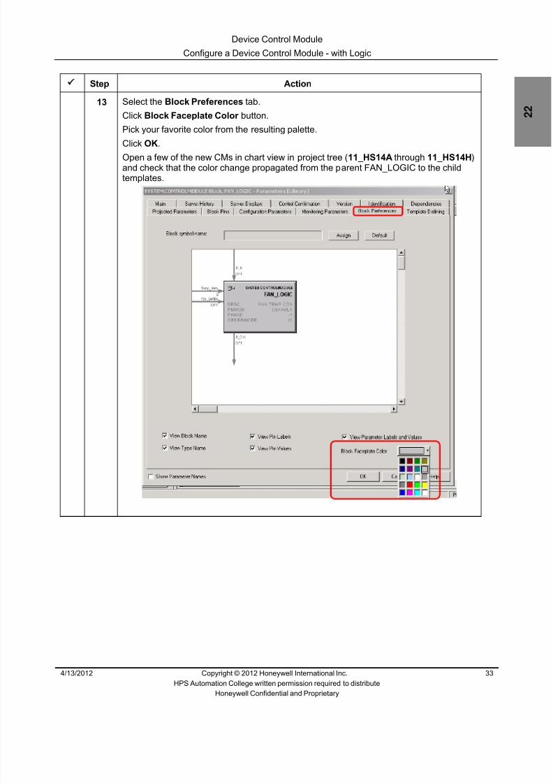
8/9/2019 Student Course Book- Automation
http://slidepdf.com/reader/full/student-course-book-automation 659/1165
Device Control Module
Configure a Device Control Module - with Logic
4/13/2012 Copyright © 2012 Honeywell International Inc. 33
HPS Automation College written permission required to distributeHoneywell Confidential and Proprietary
Step Action
13 Select the Block Preferences tab.
Click Block Faceplate Color button.
Pick your favorite color from the resulting palette.
Click OK .
Open a few of the new CMs in chart view in project tree ( 11_HS14A through 11_HS14H )and check that the color change propagated from the parent FAN_LOGIC to the childtemplates.

8/9/2019 Student Course Book- Automation
http://slidepdf.com/reader/full/student-course-book-automation 660/1165
Device Control Module
Configure a Device Control Module - with Logic
34 Copyright © 2012 Honeywell International Inc. 4/13/2012
HPS Automation College written permission required to distributeHoneywell Confidential and Proprietary
Load and Validate Control Modules
Step Action
1 Select and load CMs 11_HS14A though 11_HS14H and CMs HS_A through HS_H .
2 If the CMs were not activated when they were loaded (if the “Automatically change…”checkbox was not checked), activate the CMs from the Monitoring tab.

8/9/2019 Student Course Book- Automation
http://slidepdf.com/reader/full/student-course-book-automation 661/1165

8/9/2019 Student Course Book- Automation
http://slidepdf.com/reader/full/student-course-book-automation 662/1165
Device Control Module
Configure a Device Control Module - with Logic
36 Copyright © 2012 Honeywell International Inc. 4/13/2012
HPS Automation College written permission required to distributeHoneywell Confidential and Proprietary
Step Action
4Containment View:
5 Open Station and recall/refresh the Debutanizer_123 graphic.

8/9/2019 Student Course Book- Automation
http://slidepdf.com/reader/full/student-course-book-automation 663/1165
Device Control Module
Configure a Device Control Module - with Logic
4/13/2012 Copyright © 2012 Honeywell International Inc. 37
HPS Automation College written permission required to distributeHoneywell Confidential and Proprietary
Step Action
6 Check the Fans status and the value of 11_TI25 as indicated below.
Click the Fan Control button to call the faceplate popup: The FANS are currently OFF .
• Use the Fan Control button to set all the fans to the ON state.• Wait until all fans turn off. This will happen just after the temperature
11_TI25 reaches 260 and is reset back to 0.0.• As the temperature of 11_TI25 rises, observe the logic allowing the
appropriate fans to turn on. See the following reference section.

8/9/2019 Student Course Book- Automation
http://slidepdf.com/reader/full/student-course-book-automation 664/1165
Device Control Module
Configure a Device Control Module - with Logic
38 Copyright © 2012 Honeywell International Inc. 4/13/2012
HPS Automation College written permission required to distributeHoneywell Confidential and Proprietary
Step Action
7 Green indicates that the Fans are in the RUN state. Red indicates that the Fans are inthe STOP state.
Reference
Temperature value of 11_TI25 and the state of the Fans.
Temperature11_TI25 FANA FANB FANC FAND FANE FANF FANG FANH
55 to 60 ON OFF OFF OFF OFF OFF OFF OFF
60 to 65 ON ON OFF OFF OFF OFF OFF OFF
65 to 70 ON ON ON OFF OFF OFF OFF OFF
70 to 75 ON ON ON ON OFF OFF OFF OFF
75 to 80 ON ON ON ON ON OFF OFF OFF
80 to 85 ON ON ON ON ON ON OFF OFF
85 to 90 ON ON ON ON ON ON ON OFF
90 to 95 ON ON ON ON ON ON ON ON

8/9/2019 Student Course Book- Automation
http://slidepdf.com/reader/full/student-course-book-automation 665/1165
Device Control Module
Configure a Device Control Module - with Interlock
4/13/2012 Copyright © 2012 Honeywell International Inc. 39
HPS Automation College written permission required to distributeHoneywell Confidential and Proprietary
Configure a Device Control Module - with Interlock
Practice
Objective
• Configuring a Device Control Module for reflux pumps P62 and P63, and feed pumps P68and P69
• Use the Permissive and Safety interlocks of the Device Control Block
• Understand block name references in CM and SCM
Prerequisites
• Experion PKS Server or Client machine with Experion PKS Engineering Tools
• Debutanizer_123 graphic loaded on the Server. [This is required (at a later time) to checkthe control strategy built in this lab.]
• Control Builder running with one or two Project/Monitor tree windows open
• SCE Controller and IOMs configured
• Configure Data Acquisition Control Module and configure PID Control Module labs arecompleted
• Excel Data Exchange open with the simulation spreadsheet loaded

8/9/2019 Student Course Book- Automation
http://slidepdf.com/reader/full/student-course-book-automation 666/1165
Device Control Module
Configure a Device Control Module - with Interlock
40 Copyright © 2012 Honeywell International Inc. 4/13/2012
HPS Automation College written permission required to distributeHoneywell Confidential and Proprietary
Introduction
• In this lab, the control for a pair of pumps, P62 and P63, is developed.
• The Operator provides a Start command for Pump P62
• If P62 does not start within 20 seconds from the Start command, then P63 will start
• At any time, only one pump can be running
• This strategy will be built, loaded, and tested
• Device Control modules for the other pumps are then imported into the project
The three interlocks used for Device Controls are listed below.
• The same logic is repeated for the Feed pumps P68 (11_HS68) and P69 (11_HS69)
1. Process Permissive Interlock (PI[0..2]
2. Process Override Interlock (OI[0..2]
3. Safety Interlock (SI)
• These interlocks are associated with Device Control Block status values; that is,State 0 and 1 for 2-state devices and State 0, 1, and 2 for 3-state devices
• The Safety Interlock has the highest Priority and CANNOT be bypassed, while ProcessPermissive Interlocks have the lowest priority
• Override Interlocks OI[0..2], when active, force the commanded output (OP) to therespective state regardless of the condition of the Permissive Interlocks. The operator cannotcommand OP to a different state when the Override Interlock is active.
• When BYPPERM is ON, an operator is able to change the OP regardless of the state of theOverride interlocks (BYPASS = ON). This does not affect the Safety Override Interlock(SI). An Operator cannot bypass the Safety Interlock to change the OP. When you resetthe BYPASS parameter to OFF, any existing Override Interlocks, OI[0..2], take effectimmediately. Note: The default is OFF (unchecked - we are not using the Bypass optionhere.)

8/9/2019 Student Course Book- Automation
http://slidepdf.com/reader/full/student-course-book-automation 667/1165
Device Control Module
Configure a Device Control Module - with Interlock
4/13/2012 Copyright © 2012 Honeywell International Inc. 41
HPS Automation College written permission required to distributeHoneywell Confidential and Proprietary
Procedure
Create a Control Module
Step Action1
ATTENTION
The screen captures for this lab assume the use ofSeries A IO. If you are using Series C IO, please beaware that you will be using the PV parameter for all ofyour Series C DI connections and NOT the PVFLparameter.
Create new Control Module and configure CM parametersCreate a new Control Module.
Double-click the blank space in the chart view
Enter the following details in the Main Tab.
Tag Name: 11_HS62
Item Name: 11_HS62_Item
Parent Asset : Pumps_C11
Description: P-62 Debutanizer Reflux Pump
Accept the default for any remaining parameters on this tab.

8/9/2019 Student Course Book- Automation
http://slidepdf.com/reader/full/student-course-book-automation 668/1165
Device Control Module
Configure a Device Control Module - with Interlock
42 Copyright © 2012 Honeywell International Inc. 4/13/2012
HPS Automation College written permission required to distributeHoneywell Confidential and Proprietary
Step Action
2 Click the Server Displays tab.
Enter the following Display details:
Point Detail Display: sysDtldevctla
Click OK
ATTENTION
The Point Detail display 11_HS62 in Station will havea standard Honeywell Device Control Point faceplate.
3 Save and close 11_HS62 .
Assign 11_HS62 to your CEE (CEESCEFB61 or SIM_CEEC300).

8/9/2019 Student Course Book- Automation
http://slidepdf.com/reader/full/student-course-book-automation 669/1165
Device Control Module
Configure a Device Control Module - with Interlock
4/13/2012 Copyright © 2012 Honeywell International Inc. 43
HPS Automation College written permission required to distributeHoneywell Confidential and Proprietary
Add Function Blocks to a CM
The IOMs configured in the Configure C200E Hardware and Series A IOM/Configure C300 Hardware and Series C IOM lab are used here.
Step Action
1 Double-click the CM 11_HS62 in the Project window to open the chart view.
2 In the chart view of 11_HS62, add Function Blocks from the respective Library familiesaccording to the following sequence:
Block Family Block Sequence
C200E:
IOCHANNEL
C300:
SERIES_C_IO DI-HV
DICHANNEL (A)
LOGIC OR (B)
UTILITY FLAG (C)
DEVCTL DEVCTL (D)
C200E:
IOCHANNEL
C300:
SERIES_C_IO DO-24B
DOCHANNEL (E)
ATTENTION
For more information on how to add function blocks toa CM, refer to the Knowledge Builder, ExperionR400 > Configuration > Control Building User’sGuide > Creating a Control Module > Creating andsaving a Control Module> Creating an instance ofa basic function block .
When you insert the blocks, one by one, according tothe above sequence, each one is assigned anexecution order (ORDERINCM) automatically,increasing in multiples of 10. ORDERINCM determinesthe relative execution order of the block within the CMin ascending order. You can change this parameter, ifrequired. Enter a number from 0 to 65535 in this field.

8/9/2019 Student Course Book- Automation
http://slidepdf.com/reader/full/student-course-book-automation 670/1165
Device Control Module
Configure a Device Control Module - with Interlock
44 Copyright © 2012 Honeywell International Inc. 4/13/2012
HPS Automation College written permission required to distributeHoneywell Confidential and Proprietary
Step Action
3 After adding all the blocks, arrange them as shown below.• The explanation for each block follows:
ATTENTION
The DI and DO channels in the screen capture mightlook different if you are using Series C I/O
(A) DICHANNELA: This block provides feedback from the field for pump P62 indicating theactual field state of P62 as follows:
DICHANNELA Status P62 State
ON START (i.e., Running)
OFF STOP
(B) ORA – allows either a signal from FLAGA or HS63 to force the pump off.
(C) FLAGA – Used to give a manual Start command to the pump P62.
(D) DEVCTLA – Device Control Block that provides the user-friendly interface to the digital I/Os.
(E) DOCHANNELA – the actual signal to pump P62 in the field for the START/STOP command.
A
B
C
D
E
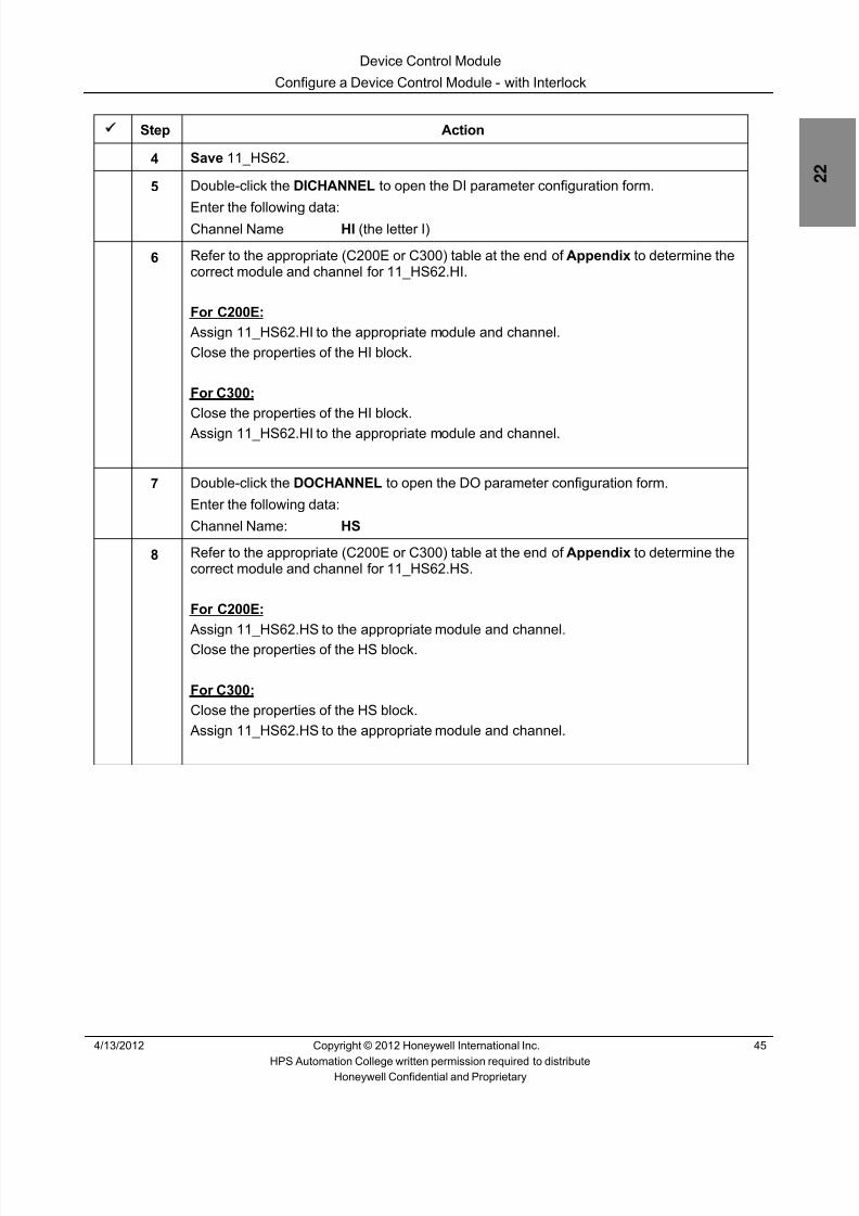
8/9/2019 Student Course Book- Automation
http://slidepdf.com/reader/full/student-course-book-automation 671/1165
Device Control Module
Configure a Device Control Module - with Interlock
4/13/2012 Copyright © 2012 Honeywell International Inc. 45
HPS Automation College written permission required to distributeHoneywell Confidential and Proprietary
Step Action
4 Save 11_HS62.
5 Double-click the DICHANNEL to open the DI parameter configuration form.
Enter the following data:Channel Name HI (the letter I)
6 Refer to the appropriate (C200E or C300) table at the end of Appendix to determine thecorrect module and channel for 11_HS62.HI.
For C200E: Assign 11_HS62.HI to the appropriate module and channel.Close the properties of the HI block.
For C300:Close the properties of the HI block.
Assign 11_HS62.HI to the appropriate module and channel.
7 Double-click the DOCHANNEL to open the DO parameter configuration form.
Enter the following data:
Channel Name: HS
8 Refer to the appropriate (C200E or C300) table at the end of Appendix to determine thecorrect module and channel for 11_HS62.HS.
For C200E: Assign 11_HS62.HS to the appropriate module and channel.Close the properties of the HS block.
For C300:Close the properties of the HS block.
Assign 11_HS62.HS to the appropriate module and channel.

8/9/2019 Student Course Book- Automation
http://slidepdf.com/reader/full/student-course-book-automation 672/1165
Device Control Module
Configure a Device Control Module - with Interlock
46 Copyright © 2012 Honeywell International Inc. 4/13/2012
HPS Automation College written permission required to distributeHoneywell Confidential and Proprietary
Step Action
9 Configure the Device Control.
Double-click the Device Control Block.
Click the Main tab.
Enter the following:
Name: DEVCTLA
Description: P-62 Debutanizer Reflux Pump

8/9/2019 Student Course Book- Automation
http://slidepdf.com/reader/full/student-course-book-automation 673/1165
Device Control Module
Configure a Device Control Module - with Interlock
4/13/2012 Copyright © 2012 Honeywell International Inc. 47
HPS Automation College written permission required to distributeHoneywell Confidential and Proprietary
Step Action
10 Enter the Block Sizing parameters in the Main tab as:
Number Of Inputs: 1
Number Of Outputs: 1
Number Of States: 2
Enter the State names in the Main tab as:
State 1 Name: START
State 0 Name: STOP
Accept the defaults for any remaining parameters on this tab.

8/9/2019 Student Course Book- Automation
http://slidepdf.com/reader/full/student-course-book-automation 674/1165
Device Control Module
Configure a Device Control Module - with Interlock
48 Copyright © 2012 Honeywell International Inc. 4/13/2012
HPS Automation College written permission required to distributeHoneywell Confidential and Proprietary
Step Action
11 Click the Inputs tab.
Enter the following details:
Number of Digital Inputs: 1 (default)
Input 1 unselected checkbox: STOP
Input 1 selected checkbox: START
12 Click the Output tab.
Enter the following data:
Number of Digital Outputs: 1
Outputs State 1 checkbox: Selected
Outputs State 0 checkbox: Not Selected
Select the Seal In Option .• See online help for additional information on the Seal In Option
Accept the defaults for any remaining parameters on this tab.

8/9/2019 Student Course Book- Automation
http://slidepdf.com/reader/full/student-course-book-automation 675/1165
Device Control Module
Configure a Device Control Module - with Interlock
4/13/2012 Copyright © 2012 Honeywell International Inc. 49
HPS Automation College written permission required to distributeHoneywell Confidential and Proprietary
Step Action
13 Click the Alarms tab.
Enter the following data:
Time toSTOP Time toSTART Priority Severity
Command Disagree 20 20 LOW 0
Command Fail 10 10 HIGH 0
Accept the defaults for any remaining parameters.
14 Click OK .
15 Click File > Save to save the CM 11_HS62 .
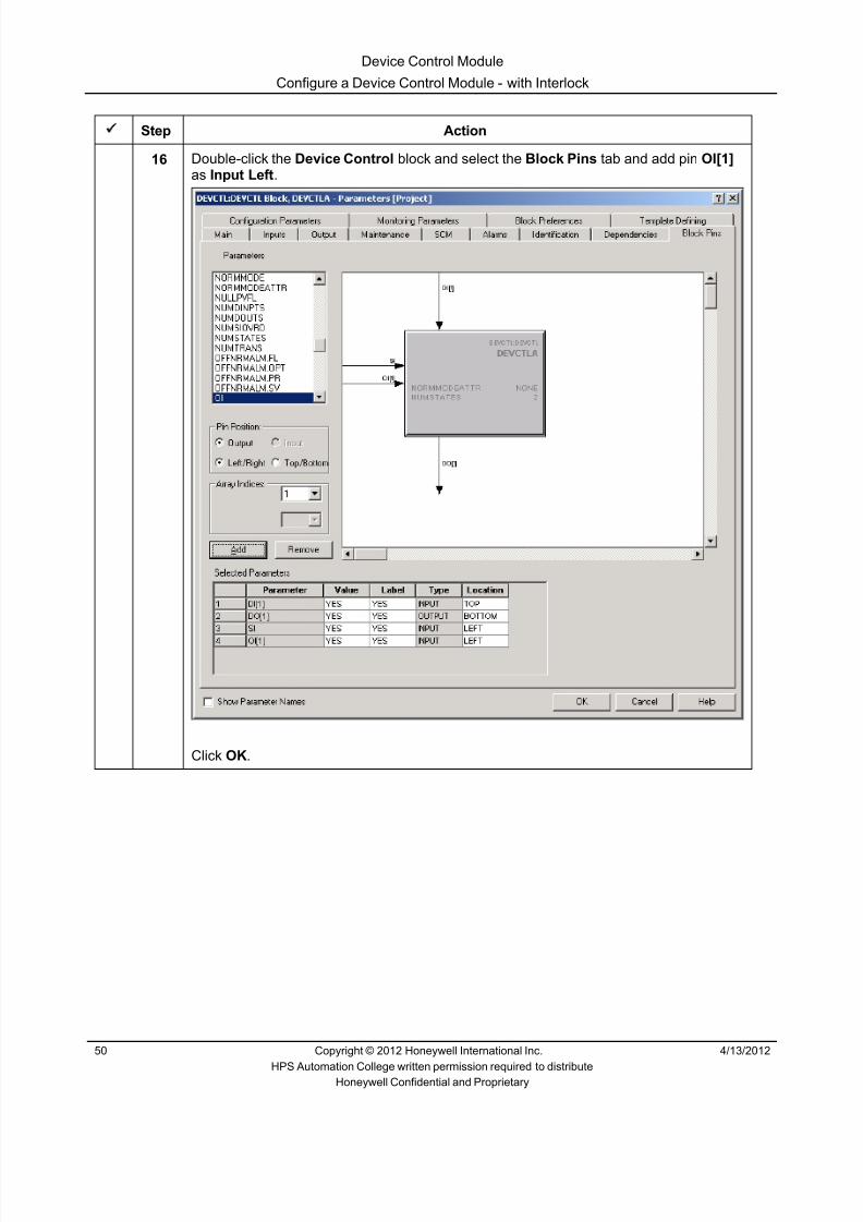
8/9/2019 Student Course Book- Automation
http://slidepdf.com/reader/full/student-course-book-automation 676/1165
Device Control Module
Configure a Device Control Module - with Interlock
50 Copyright © 2012 Honeywell International Inc. 4/13/2012
HPS Automation College written permission required to distributeHoneywell Confidential and Proprietary
Step Action
16 Double-click the Device Control block and select the Block Pins tab and add pin OI[1]as Input Left .
Click OK .

8/9/2019 Student Course Book- Automation
http://slidepdf.com/reader/full/student-course-book-automation 677/1165
Device Control Module
Configure a Device Control Module - with Interlock
4/13/2012 Copyright © 2012 Honeywell International Inc. 51
HPS Automation College written permission required to distributeHoneywell Confidential and Proprietary
Step Action
17 Double-click the FLAG block.
Enter the following details:
Name: FLAGA
Description: Turn Reflux Pump ON
Click OK .
18 Double-click the ORA block.
Invert the input IN(2) by selecting the checkbox for item 2.
Click OK .

8/9/2019 Student Course Book- Automation
http://slidepdf.com/reader/full/student-course-book-automation 678/1165
Device Control Module
Configure a Device Control Module - with Interlock
52 Copyright © 2012 Honeywell International Inc. 4/13/2012
HPS Automation College written permission required to distributeHoneywell Confidential and Proprietary
Step Action
19
ATTENTION
This step is optional. Use either the Full Name option,or the Short Name option as desired.
Click Tools System Preferences. In the ‘Relative Reference Display Option’ field,select Short Name so the user does not have to enter more information than required.
Click OK .The following message requesting to close all other (remotely opened) Control Buildersessions appears.
Click OK on the message box.

8/9/2019 Student Course Book- Automation
http://slidepdf.com/reader/full/student-course-book-automation 679/1165
Device Control Module
Configure a Device Control Module - with Interlock
4/13/2012 Copyright © 2012 Honeywell International Inc. 53
HPS Automation College written permission required to distributeHoneywell Confidential and Proprietary
Step Action
20 Arrange and connect the blocks as shown below:
ATTENTION
For details of each block connection, refer to the chartin the next step.
A
C
B
E
D
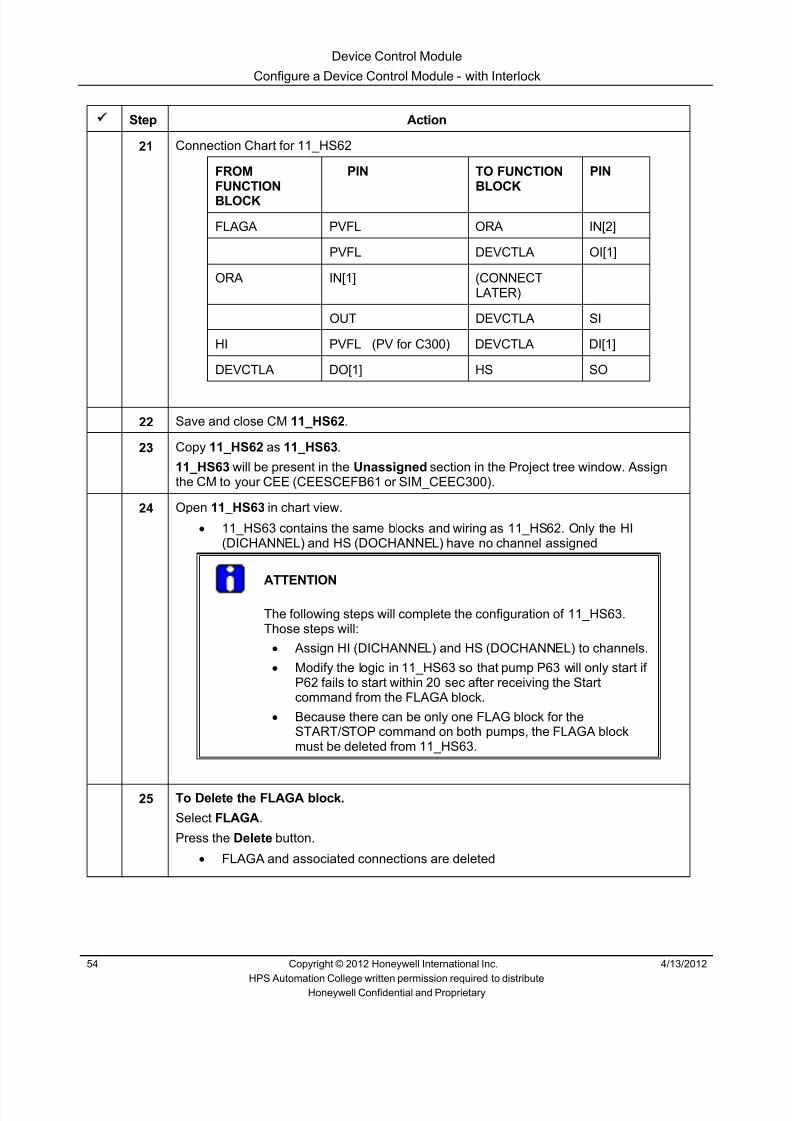
8/9/2019 Student Course Book- Automation
http://slidepdf.com/reader/full/student-course-book-automation 680/1165
Device Control Module
Configure a Device Control Module - with Interlock
54 Copyright © 2012 Honeywell International Inc. 4/13/2012
HPS Automation College written permission required to distributeHoneywell Confidential and Proprietary
Step Action
21 Connection Chart for 11_HS62
FROMFUNCTIONBLOCK
PIN TO FUNCTIONBLOCK
PIN
FLAGA PVFL ORA IN[2]
PVFL DEVCTLA OI[1]
ORA IN[1] (CONNECTLATER)
OUT DEVCTLA SI
HI PVFL (PV for C300) DEVCTLA DI[1]
DEVCTLA DO[1] HS SO
22 Save and close CM 11_HS62 .
23 Copy 11_HS62 as 11_HS63 .
11_HS63 will be present in the Unassigned section in the Project tree window. Assignthe CM to your CEE (CEESCEFB61 or SIM_CEEC300).
24 Open 11_HS63 in chart view.• 11_HS63 contains the same blocks and wiring as 11_HS62. Only the HI
(DICHANNEL) and HS (DOCHANNEL) have no channel assigned
ATTENTION
The following steps will complete the configuration of 11_HS63.Those steps will:
• Assign HI (DICHANNEL) and HS (DOCHANNEL) to channels.• Modify the logic in 11_HS63 so that pump P63 will only start if
P62 fails to start within 20 sec after receiving the Startcommand from the FLAGA block.
• Because there can be only one FLAG block for theSTART/STOP command on both pumps, the FLAGA blockmust be deleted from 11_HS63.
25 To Delete the FLAGA block.
Select FLAGA .
Press the Delete button.• FLAGA and associated connections are deleted

8/9/2019 Student Course Book- Automation
http://slidepdf.com/reader/full/student-course-book-automation 681/1165
Device Control Module
Configure a Device Control Module - with Interlock
4/13/2012 Copyright © 2012 Honeywell International Inc. 55
HPS Automation College written permission required to distributeHoneywell Confidential and Proprietary
Step Action
26 Drag and drop the following function blocks to 11_HS63 .
Block Family BlockLOGIC ONDELAYLOGIC AND
27 Configure the ONDELAY gate.
Double-click the ONDELAYA Block.
Enter following details:
Name: ONDELAYA
Delay Time: 20 (Delay time is in seconds)
Accept the defaults for any remaining parameters.
Click OK .
ATTENTION
The ONDELAY block delays the Start command toPump P63 by 20 seconds.

8/9/2019 Student Course Book- Automation
http://slidepdf.com/reader/full/student-course-book-automation 682/1165
Device Control Module
Configure a Device Control Module - with Interlock
56 Copyright © 2012 Honeywell International Inc. 4/13/2012
HPS Automation College written permission required to distributeHoneywell Confidential and Proprietary
Step Action
28 Configure the ANDA gate.• This block sends the Start command, to pump P63 (delayed by 20 sec), if
pump P62 has not started
Double-click the ANDA function block.Enter ANDA in the Name field.
Invert the input IN(2) by selecting the checkbox for item 2.
When finished, click OK to close the ANDA function block.• This option inverts the P62 Start signal. So if P62 has not started after 20 sec,
then only P63 will start
29 Refer to the appropriate (C200E or C300) table at the end of Appendix to determine thecorrect module and channel for 11_HS63.HI.
For C200E:Display the properties of the HI block.
Assign 11_HS63.HI to the appropriate module and channel.Close the properties of the HI block.
For C300: Assign 11_HS63.HI to the appropriate module and channel.

8/9/2019 Student Course Book- Automation
http://slidepdf.com/reader/full/student-course-book-automation 683/1165
Device Control Module
Configure a Device Control Module - with Interlock
4/13/2012 Copyright © 2012 Honeywell International Inc. 57
HPS Automation College written permission required to distributeHoneywell Confidential and Proprietary
Step Action
30 Refer to the appropriate (C200E or C300) table at the end of Appendix to determine thecorrect module and channel for 11_HS63.HS.
For C200E:Display the properties of the HI block.
Assign 11_HS63.HS to the appropriate module and channel.Close the properties of the HS block.
For C300: Assign 11_HS63.HS to the appropriate module and channel.
31 Wire the blocks as follows:
Wire parameter 11_HS62.HI.PVFL (PV for C300 ) to the IN[2] pin of the ANDA block with
a parameter connector.Wire the Out Pin of the ONDELAYA block to the IN[1] pin of the ANDA block.
Wire parameter 11_HS62.FLAGA.PVFL to the IN pin of the ONDELAYA block with aparameter connector.
• The ANDA gate output is true if ANDA receives the TRUE signal at IN(1) and aFALSE signal at IN(2) as IN(2) is inverted

8/9/2019 Student Course Book- Automation
http://slidepdf.com/reader/full/student-course-book-automation 684/1165
Device Control Module
Configure a Device Control Module - with Interlock
58 Copyright © 2012 Honeywell International Inc. 4/13/2012
HPS Automation College written permission required to distributeHoneywell Confidential and Proprietary
Step Action
32 Wire parameter 11_HS62.HI. PVFL (PV for C300 ) to the IN[1] pin of the ORA block witha parameter connector.
Wire parameter 11_HS62.FLAGA.PVFL to the IN[2] pin of the ORA block with a
parameter connector.Complete the remaining connections as shown below.
• The ANDA gate sends the START command to the Pump through OI[1] only ifP62 does not start after 20 sec
33 Save and close 11_HS63 .
34 Open CM 11_HS62 to configure the SI interlock (as shown in the following steps).

8/9/2019 Student Course Book- Automation
http://slidepdf.com/reader/full/student-course-book-automation 685/1165
Device Control Module
Configure a Device Control Module - with Interlock
4/13/2012 Copyright © 2012 Honeywell International Inc. 59
HPS Automation College written permission required to distributeHoneywell Confidential and Proprietary
Step Action
35Wire parameter 11_HS63.HI. PVFL (PV for C300 ) to the IN[1] of ORA.
36 Save and close 11_HS62 .
37 From the Project Tree window, import (with CEE assignment) CMs 11_HS68 and11_HS69 . Import from:
C:\ Users\Public\Public Documents\Honeywell\Experion PKS\IXPORT\Student_DB\Series_A (or _C)
ATTENTION
Follow the procedures in the Import/Export Lab, if you need a refresher.
If you are Using SIMC200E/C200E the path for Database isC:\ Users\Public\Public Documents\Honeywell\Experion PKS\IXPORT\Student_DB\Series_A
If you are Using SIMC300/C300 the path for Database isC:\ Users\Public\Public Documents\Honeywell\Experion PKS\IXPORT\Student_DB\Series_C

8/9/2019 Student Course Book- Automation
http://slidepdf.com/reader/full/student-course-book-automation 686/1165
Device Control Module
Configure a Device Control Module - with Interlock
60 Copyright © 2012 Honeywell International Inc. 4/13/2012
HPS Automation College written permission required to distributeHoneywell Confidential and Proprietary
Step Action
38 Open the Project Tree window and verify that the Parent asset of 11_HS68 and11_HS69 is Pumps_C11. If not, change it to Pumps_C11 .
39 Download (with activation) 11_HS62 , 11_HS63 , 11_HS68 , 11_HS69 .
40 Use the Monitoring Tree window to verify all the CMs are active (green).
41 Open the Debutanizer_123 graphics on Station. If the graphics already loaded thenreload the page so that new points are recognized.
• All four pumps are OFF (Red)
42 Select the ON command for the pumps in the combo box.
• P62 and P68 are ON (green)• If P62 and P68 fail – which they will after sometime (up to 60 seconds) because of
the simulation in Tie_Back_New, then P63 and P69 will be commanded to start• After P62 and P68 have been commanded to start, it will be at least 20 seconds
before P63 and P69 are commanded to start because of the OnDelay functionblocks in P63 and P69
• Therefore, after P62 and P68 turn on, it can be from 20 to 80 seconds (plusscreen update) before P63 and P69 turn on.
• This happens because P62 feedback indicates that DI(1) is not ON within 20 secafter the Operator issues a start command

8/9/2019 Student Course Book- Automation
http://slidepdf.com/reader/full/student-course-book-automation 687/1165
1
1
Honeywell ConfidentialCopyright © 2012 Honeywell International Inc.
4/13/2012
Describe Auxiliary Function Blocks
Math and Auxiliary Function Blocks Describe Auxiliary Function BlocksMath and Auxiliary Function Blocks Describe Auxiliary Function Blocks
Honeywell
Honeywell ConfidentialCopyright © 2012 Honeywell International Inc.
4/13/20122
Topics
• In this lesson, you will learn about different Auxiliary Blocks
– AUXCALC block
– Counter Block
Math and Auxiliary Function Blocks Describe Auxiliary Function Blocks

8/9/2019 Student Course Book- Automation
http://slidepdf.com/reader/full/student-course-book-automation 688/1165
2
Honeywell
Honeywell ConfidentialCopyright © 2012 Honeywell International Inc.
4/13/20123
Auxiliary Blocks
• Auxiliary blocks perform mathematical functions
Math and Auxiliary Function Blocks Describe Auxiliary Function Blocks
Honeywell
Honeywell ConfidentialCopyright © 2012 Honeywell International Inc.
4/13/20124
• Previously, the AUXCALC block was used for performing morecomplicated mathematical functions
• The AUXCALC block has mathematical and logical capabilities – The AUXCALC block uses a lot of memory (2452 bytes according to the
CEE Detail page)
• Simpler calculation blocks have been developed
– Use less controller memory – Ensure optimum use of memory
AUXCALC Block
Math and Auxiliary Function Blocks Describe Auxiliary Function Blocks

8/9/2019 Student Course Book- Automation
http://slidepdf.com/reader/full/student-course-book-automation 689/1165
3
Honeywell
Honeywell ConfidentialCopyright © 2012 Honeywell International Inc.
4/13/20125
AUXCALC Block Constants
• In R400, a ‘Constants’ tab was added for calculator blocks – Can enable and enter values for up to 8 constants – Can define the access level required to change the constants – Can be used in expressions or as inputs or outputs
Constants used inExpressions
Constants used asinputs and outputs
Math and Auxiliary Function Blocks Describe Auxiliary Function Blocks
Honeywell
Honeywell ConfidentialCopyright © 2012 Honeywell International Inc.
4/13/20126
Topics
• In this lesson, you will learn about different Auxiliary Blocks
– AUXCALC block
– Counter Block
Math and Auxiliary Function Blocks Describe Auxiliary Function Blocks

8/9/2019 Student Course Book- Automation
http://slidepdf.com/reader/full/student-course-book-automation 690/1165
4
Honeywell
Honeywell ConfidentialCopyright © 2012 Honeywell International Inc.
4/13/20127
Counter Block Overview
• Provides a way to count events – Counts up based on CNTUPFL – Counts down based on CNTDNFL – Outputs are: Count and “count limit reached” flags
• “Count Limits” determined by equation (Eq A to Eq H available)• Can be implemented in the following CEE environments
– C200E, SIM-C200E, C300, SIM-C300, ACE, SIM-ACE
Math and Auxiliary Function Blocks Describe Auxiliary Function Blocks
Honeywell
Honeywell ConfidentialCopyright © 2012 Honeywell International Inc.
4/13/20128
Counter Block Functions
• The counter can be reset to 0 (RESETFL), paused (PAUSEFL), or set toa specific value (LOADFL, ININT32)
• Output flags (QUFL, QDFL) are turned on or off based on: – Input (ININT32) – Count (OUTINT32) – Algorithm configured (Eq A to Eq H)
• Ex: Eq A: QUFL is true if OUT ≥ IN; QDFL is true if OUT ≤ 0
Math and Auxiliary Function Blocks Describe Auxiliary Function Blocks

8/9/2019 Student Course Book- Automation
http://slidepdf.com/reader/full/student-course-book-automation 691/1165
5
Honeywell
Honeywell ConfidentialCopyright © 2012 Honeywell International Inc.
4/13/20129
• CNTUPFL causes the count to increment• CNTDNFL causes the count to decrement• Count on level flag (CNTVLVFL) – unchecked
– Count inputs are evaluated as edge-triggered quantities – Value increments / decrements if the input has changed from OFF to ON
• Count on level flag (CNTVLVFL) – checked – Count inputs are evaluated as level triggered quantities – Value increments / decrements on every execution cycle while the input is ON
Count on Level vs. Count on Transition
t
t
If both CNTUPFL and CNTDNFL are ON(or both transition to ON), or if both areOFF (or both transition to OFF), then thecount does not change.
Math and Auxiliary Function Blocks Describe Auxiliary Function Blocks
Honeywell
Honeywell ConfidentialCopyright © 2012 Honeywell International Inc.
4/13/201210
Counter Inputs
• Accepts Integer 32, Float 64, and Boolean inputs
• Selection of the input format is based on the ‘Input Selection Specifier’(SELINT32FL) parameter – If checked, input format selected is INT32 – If unchecked, input format selected is FLOAT64
• If the selected input format is FLOAT64, theInput Clamping Option (INCLAMPOPT)determines if special handling is requiredfor out of range or invalid input values
Math and Auxiliary Function Blocks Describe Auxiliary Function Blocks

8/9/2019 Student Course Book- Automation
http://slidepdf.com/reader/full/student-course-book-automation 692/1165
6
Honeywell
Honeywell ConfidentialCopyright © 2012 Honeywell International Inc.
4/13/201211
Float 64 Input Conversions
• Value clamping, or substitution for invalid or out of range values
Value fetched orattempted to store INCLAMPOPT IN.FLOAT64 value
Value for Counter LoadOperation
Value for LimitChecking
Value > 2,147,483,647.0 TRUE 2,147,483,647.0 2,147,483,647 2,147,483,647
Value > 2,147,483,647.0 FALSE NaNValue will not be loaded.
Previous Counter value isretained
NaN. Comparison is alwaysFALSE
Value within− 2,147,483,648.0 to
+2,147,483,647.0
TRUE / FALSE Floating point valuetruncated to integer
equivalentTruncated In teger value Truncated In teger value
Value < − 2,147,483,648.0 TRUE −2,147,483,648.0 −2,147,483,648 −2,147,483,648
Value < − 2,147,483,648.0 FALSE NaNValue will not be loaded.
Previous Counter value isretained
NaN. Comparison is alwaysFALSE
NaN TRUE / FALSE NaNValue will not be loaded.
Previous Counter value isretained
NaN. Comparison is alwaysFALSE
Math and Auxiliary Function Blocks Describe Auxiliary Function Blocks
Honeywell
Honeywell ConfidentialCopyright © 2012 Honeywell International Inc.
4/13/201212
Counter Equations
Equation CounterOverflow
CounterUnderflow
QUFL TRUE) QDFL TRUE)
A +2,147,483,647 - 2,147,483,647 OUT >= IN OUT <= 0
B +2,147,483,647 - 2,147,483,647 OUT >= IN OUT =-2,147,483,647
C +2,147,483,647 0 OUT >= IN OUT = 0
D IN 0 OUT >= IN OUT = 0
E +2,147,483,647 - 2,147,483,647 OUT >= 0 OUT <= IN
F +2,147,483,647 - 2,147,483,647 OUT =+2,147,483,647
OUT <= IN
G 0 - 2,147,483,647 OUT = 0 OUT <= IN
H 0 -IN OUT = 0 OUT = IN
Math and Auxiliary Function Blocks Describe Auxiliary Function Blocks

8/9/2019 Student Course Book- Automation
http://slidepdf.com/reader/full/student-course-book-automation 693/1165
7
Honeywell
Honeywell ConfidentialCopyright © 2012 Honeywell International Inc.
4/13/201213
Summary
• Auxiliary Function blocks provide a variety of configurable functions forconditioning, calculating, and compensating PV data in support ofRegulatory Control Functions
• In Experion PKS R400, the Constant tab and Expression Descriptionparameters are added to calculator blocks
• Counters can be used to provide most features available in PLCcounters
Math and Auxiliary Function Blocks Describe Auxiliary Function Blocks
Honeywell
Honeywell ConfidentialCopyright © 2012 Honeywell International Inc.
4/13/201214
Conclusion
Describe Auxiliary Function Blocks
CompletionCertificate
Proceed to the next lesson in your course material.
Math and Auxiliary Function Blocks Describe Auxiliary Function Blocks

8/9/2019 Student Course Book- Automation
http://slidepdf.com/reader/full/student-course-book-automation 694/1165
8
15
Honeywell ConfidentialCopyright © 2012 Honeywell International Inc.
4/13/2012
Describe MATH Function Blocks
Math and Auxiliary Function Blocks Describe MATH Function BlocksMath and Auxiliary Function Blocks Describe MATH Function Blocks
Honeywell
Honeywell ConfidentialCopyright © 2012 Honeywell International Inc.
4/13/201216
Introduction
• In this lesson, you will learn about
– Overview of MATH function blocks
– Rolling Average Function block
Math and Auxiliary Function Blocks Describe MATH Function Blocks

8/9/2019 Student Course Book- Automation
http://slidepdf.com/reader/full/student-course-book-automation 695/1165
9
Honeywell
Honeywell ConfidentialCopyright © 2012 Honeywell International Inc.
4/13/201217
Math Blocks
• Math blocks perform simple mathematical
functions
• Use these blocks rather than the AUXCALCblock when performing simple math – More efficient use of memory – AUXCALC block uses 2452 bytes – Math blocks use 50 – 600 (see next page)
Mathematical function blocks providedunder the MATH Library
Math and Auxiliary Function Blocks Describe MATH Function Blocks
Honeywell
Honeywell ConfidentialCopyright © 2012 Honeywell International Inc.
4/13/201218
Library of Math Blocks
• Math blocks provide efficient usage of memory
Block Name Function Memory Used
ADD (8 input connections) Sum of n arguments Approximately 110 bytes
SUB (2 input connections) Subtraction Approximately 60 bytes
MUL (8 input connections) Product of n arguments Approximately 110 bytes
DIV (2 input connections) Division Approximately 60 bytes
MOD (2 input connections) (x MOD y) Approximately 60 bytes
ABS (1 input connection) Absolute value Approximately 50 bytes
POW (2 input connections) (x^y) Approximately 60 bytes
EXP (1 input connection) e to the power of x Approximately 50 bytes
SQRT (1 input connection) square root Approximately 50 bytes
LN (1 input connection) Natural logarithm of a number (log to the base of e) Approximately 50 bytes
LOG (1 input connection) Base 10 logarithm of a number Approximately 50 bytesNEG (1 input connection) -(x) Approximately 50 bytes
TRUNC (1 input connection) Round down to nearest integer value Approximately 50 bytes
ROLLAVG Rolling Average Approximately 600 bytes
ROUND (1 input connection) Rounded up to nearest integer value Approximately 50 bytes
1 MU = 1000 bytes
Math and Auxiliary Function Blocks Describe MATH Function Blocks

8/9/2019 Student Course Book- Automation
http://slidepdf.com/reader/full/student-course-book-automation 696/1165
10
Honeywell
Honeywell ConfidentialCopyright © 2012 Honeywell International Inc.
4/13/201219
Introduction of Rolling Average block
• Calculates a rolling average of values collected over a specified periodof time – Similar to the Rolling Average Algorithm available in the AM (TPS)
• Available in the C200E, C300, ACE (and their simulated environments)• ROLLAVG function block is added from the MATH Library in Control
Builder
Math and Auxiliary Function Blocks Describe MATH Function Blocks
Honeywell
Honeywell ConfidentialCopyright © 2012 Honeywell International Inc.
4/13/201220
Rolling Average Block Algorithm
• The Rolling Average Calculation – Collect samples in buffer at specific frequency – Save the samples to the buffer
• Mark samples as OK (good) or Bad – Calculate the average of the collected samples
Output = Sum of all samples (Good values) in buffer No. of good samples in buffer
Math and Auxiliary Function Blocks Describe MATH Function Blocks

8/9/2019 Student Course Book- Automation
http://slidepdf.com/reader/full/student-course-book-automation 697/1165
11
Honeywell
Honeywell ConfidentialCopyright © 2012 Honeywell International Inc.
4/13/201221
Frequency of Sample Collection
• The frequency of sample collectionis defined by two configurableparameters
• ROLLFREQ – Defines the number
• ROLLFRBASE – Defines the time base:
• Seconds, minutes, or hours
• Sample Period (Frequency) – Defined by ROLLFREQ and ROLLFRBASE
• Example: if ROLLFREQ is ‘4’, and ROLLFRBASE is ‘seconds’ thensamples are collected every 4 seconds
– Must be a multiple of the period of the containing CM• Example: if CM Period is 2 seconds, the sample frequency can be a
multiple of 2 i.e. 2, 4, 6, 8, and so on…
Math and Auxiliary Function Blocks Describe MATH Function Blocks
Honeywell
Honeywell ConfidentialCopyright © 2012 Honeywell International Inc.
4/13/201222
Load Time Error if Sample Period is Not a Multiple of CM
• The collection frequency of theROLLAVG block must be amultiple of the period of thecontaining CM – If not, a load error will occur – The output (rolling average)
of the block will be NaNError message at time
of download
Math and Auxiliary Function Blocks Describe MATH Function Blocks
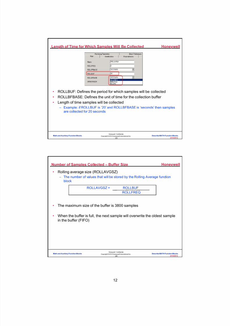
8/9/2019 Student Course Book- Automation
http://slidepdf.com/reader/full/student-course-book-automation 698/1165
12
Honeywell
Honeywell ConfidentialCopyright © 2012 Honeywell International Inc.
4/13/201223
Length of Time for Which Samples Will Be Collected
• ROLLBUF: Defines the period for which samples will be collected• ROLLBFBASE: Defines the unit of time for the collection buffer • Length of time samples will be collected
– Example: if ROLLBUF is ’20’ and ROLLBFBASE is ‘seconds’ then samplesare collected for 20 seconds
Math and Auxiliary Function Blocks Describe MATH Function Blocks
Honeywell
Honeywell ConfidentialCopyright © 2012 Honeywell International Inc.
4/13/201224
Number of Samples Collected – Buffer Size
• Rolling average size (ROLLAVGSZ) – The number of values that will be stored by the Rolling Average function
block
• The maximum size of the buffer is 3800 samples
• When the buffer is full, the next sample will overwrite the oldest samplein the buffer (FIFO)
ROLLAVGSZ = ROLLBUFROLLFREQ
Math and Auxiliary Function Blocks Describe MATH Function Blocks

8/9/2019 Student Course Book- Automation
http://slidepdf.com/reader/full/student-course-book-automation 699/1165
13
Honeywell
Honeywell ConfidentialCopyright © 2012 Honeywell International Inc.
4/13/201225
Rolling Average ‘OK’ and ‘BAD’ Value Count
• ROLLAVGOK – The number of good samples in the buffer
• Included when calculating rolling average
• ROLLAVGBAD – The number of bad samples in the buffer
• A bad sample is one whose value is NaN• Excluded when calculating the rolling average
Math and Auxiliary Function Blocks Describe MATH Function Blocks
Honeywell
Honeywell ConfidentialCopyright © 2012 Honeywell International Inc.
4/13/201226
Example: Calculate Rolling Average
• Consider the following values for calculating the rolling average – CM Period = 2 seconds – ROLLFREQ = 6 – ROLLFRBASE = seconds – ROLLBUF = 24 – ROLLBFBASE = seconds
• Number of samples collected = 4
• Values of samples collected: 4, 6, Nan, 8• Rolling Average (output) is 6
– OUT = (4+6+8)/3=6
• Block displays the good and bad values as – ROLLAVGBAD = 1 – ROLLAVGOK = 3
Math and Auxiliary Function Blocks Describe MATH Function Blocks

8/9/2019 Student Course Book- Automation
http://slidepdf.com/reader/full/student-course-book-automation 700/1165
14
Honeywell
Honeywell ConfidentialCopyright © 2012 Honeywell International Inc.
4/13/201227
Example: Calculate Rolling Average
ROLLAVGOK = 7
Number of good sampleswhen calculating the rolling
average
ROLLAVGBAD = 3
Number of bad samplesexcluded from calculating the
rolling average
ROLLAVG.OUT= 4.6
Sum of all good samplesNumber of good samples
NaN 4.6 4.7 4.8 4.5 4.6 4.5 4.5 4.5 4.6 4.5 4.94.5 4.6 4.5 4.9 NaN NaN
ROLLAVGSZ = 10
Number of FLOAT64 values that willbe collected in the Average Rolling
function block
Values stored inbuffer
Math and Auxiliary Function Blocks Describe MATH Function Blocks
Honeywell
Honeywell ConfidentialCopyright © 2012 Honeywell International Inc.
4/13/201228
• ROLLAVGRST – Used to restart the rolling average – Can be done without inactivating the
CM
• When ROLLAVGRST = ON – Sets all values = 0 – Sets ROLLAVGOK = 0 – Sets ROLLAVGBAD = 0 – Turn the ROLLAVGRST to OFF – Restart sample collection – Restarts the calculation
• Can be done by an engineer, SCM,or CAB
Resetting the Rolling Average
Math and Auxiliary Function Blocks Describe MATH Function Blocks

8/9/2019 Student Course Book- Automation
http://slidepdf.com/reader/full/student-course-book-automation 701/1165
15
Honeywell
Honeywell ConfidentialCopyright © 2012 Honeywell International Inc.
4/13/201229
Conclusion
Describe MATH Function Blocks
CompletionCertificate
Proceed to the next lesson in your course material.
Math and Auxiliary Function Blocks Describe MATH Function Blocks
Honeywell
Honeywell ConfidentialCopyright © 2012 Honeywell International Inc.
4/13/201230
This page intentionally left blank
Math and Auxiliary Function Blocks Describe MATH Function Blocks

8/9/2019 Student Course Book- Automation
http://slidepdf.com/reader/full/student-course-book-automation 702/1165
Copyright © 201 2 Honeywell International Inc.
HPS Automation College written permission required to distributeHoneywell Confidential and Proprietary
This page was intentionally left blank.

8/9/2019 Student Course Book- Automation
http://slidepdf.com/reader/full/student-course-book-automation 703/1165
4/13/2012 Copyright © 2012 Honeywell International Inc. 1
HPS Automation College written permission required to distributeHoneywell Confidential and Proprietary
Topic: Math and Auxiliary Function Blocks
Contents
Use Rolling Average Function Block ..................................................................................................... 3
Use Counter Function Block ................................................................................................................ 13

8/9/2019 Student Course Book- Automation
http://slidepdf.com/reader/full/student-course-book-automation 704/1165
2 Copyright © 2012 Honeywell International Inc. 4/13/2012
HPS Automation College written permission required to distributeHoneywell Confidential and Proprietary
This page was intentionally left blank.

8/9/2019 Student Course Book- Automation
http://slidepdf.com/reader/full/student-course-book-automation 705/1165
Math and Auxiliary Function Blocks
Use Rolling Average Function Block
4/13/2012 Copyright © 2012 Honeywell International Inc. 3
HPS Automation College written permission required to distributeHoneywell Confidential and Proprietary
Use Rolling Average Function Block
Objective
• Configure Rolling Average block
• Navigate through different parameters of Rolling Average block.
Prerequisites
• Knowledge of Configuration Studio.
• Knowledge of Control Builder
• Knowledge of navigating through Control Builder
• Knowledge Builder access
• C300/SIM-C300, C200E/SIM-C200E created and loaded in Control Builder.
TIP
The Rolling Average block can’t be assigned toC200/SIM-C200 CEE.
Introduction
• In this lab, you will learn the configuration and working of the Rolling Average block. TheRolling Average block will calculate the rolling average of the Numeric output.

8/9/2019 Student Course Book- Automation
http://slidepdf.com/reader/full/student-course-book-automation 706/1165
Math and Auxiliary Function Blocks
Use Rolling Average Function Block
4 Copyright © 2012 Honeywell International Inc. 4/13/2012
HPS Automation College written permission required to distributeHoneywell Confidential and Proprietary
Complete the following steps in Control Builder
Step Action
1 Open Control Builder through Configuration Studio.
2 Click File > New > Control Module.
3 Double click on the chart to open properties window of control module.
On Main tab enter following:
Tag Name: CM_RollAvg
Item Name: CM_RollAvg_Item
Description: < Your choice>
Parent Asset: < Any Existing Asset>
Click OK.
4 Add a NUMERIC block from the UTILITY library to CM_RollAvg.
5 Add a ROLLAVG block from the MATH library to CM_RollAvg.
6 The CM will look as shown below:

8/9/2019 Student Course Book- Automation
http://slidepdf.com/reader/full/student-course-book-automation 707/1165
Math and Auxiliary Function Blocks
Use Rolling Average Function Block
4/13/2012 Copyright © 2012 Honeywell International Inc. 5
HPS Automation College written permission required to distributeHoneywell Confidential and Proprietary
Step Action
7 Double Click on ROLLAVGA block to open properties window.
On the Main tab, enter the following:
Rollavg frequency -time span : 4
Rollavg frequency -units of time : SECONDS
RollAvg collection -time span : 40
RollAvg collection -units of time : SECONDS
Click OK.
ATTENTION
Rollavg frequency -time span (ROLLFREQ) should bea multiple of the CM period. In this case, theexecution period of the CM period was left atDEFAULT which is 1 second (default = 1 second for a50 ms CEE). 4 seconds (the ROLLFREQ) is amultiple of 1 second (the CM period).
Rollavg collection -time span (ROLLBUF) is configuredto be 40 seconds. This will cause a buffer size of 10(ROLLBUF/ROLLFREQ). Therefore, 10 samples willbe used to calculate the rolling average.

8/9/2019 Student Course Book- Automation
http://slidepdf.com/reader/full/student-course-book-automation 708/1165
Math and Auxiliary Function Blocks
Use Rolling Average Function Block
6 Copyright © 2012 Honeywell International Inc. 4/13/2012
HPS Automation College written permission required to distributeHoneywell Confidential and Proprietary
Step Action
8 Connect the function blocks as shown.
9 Save, close, and assign the CM to the CEE of SCE59 (or SIM_C300).

8/9/2019 Student Course Book- Automation
http://slidepdf.com/reader/full/student-course-book-automation 709/1165
Math and Auxiliary Function Blocks
Use Rolling Average Function Block
4/13/2012 Copyright © 2012 Honeywell International Inc. 7
HPS Automation College written permission required to distributeHoneywell Confidential and Proprietary
Step Action
10 Load and activate CM.
11 Open CM_RollAvg in the monitoring mode.
Observe that the ROLLAVGSZ (Roll average buffer size) parameter is 10 and theROLLAVGBAD parameter is incrementing.
ATTENTION
ROLLAVGBAD is the number of bad samples thathave been put into the rolling average buffer. Thisnumber is incrementing because the input to the blockis NaN (Not a Number). The rolling averagecalculation uses only good values. In this case, theinput has always been NaN (since the CM wasactivated). Because there have not been any goodvalues at the input, there are no values contributing tothe rolling average, and so the output is also Nan.
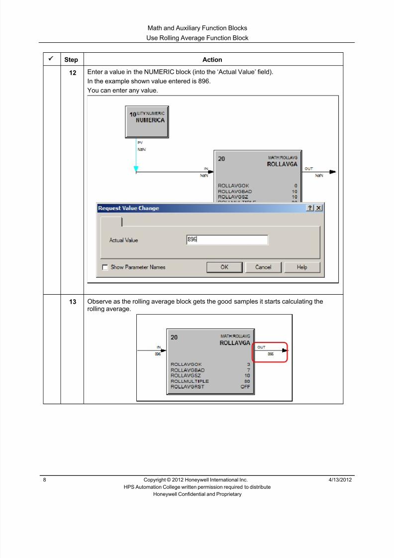
8/9/2019 Student Course Book- Automation
http://slidepdf.com/reader/full/student-course-book-automation 710/1165
Math and Auxiliary Function Blocks
Use Rolling Average Function Block
8 Copyright © 2012 Honeywell International Inc. 4/13/2012
HPS Automation College written permission required to distributeHoneywell Confidential and Proprietary
Step Action
12 Enter a value in the NUMERIC block (into the ‘Actual Value’ field).In the example shown value entered is 896.You can enter any value.
13 Observe as the rolling average block gets the good samples it starts calculating therolling average.

8/9/2019 Student Course Book- Automation
http://slidepdf.com/reader/full/student-course-book-automation 711/1165
Math and Auxiliary Function Blocks
Use Rolling Average Function Block
4/13/2012 Copyright © 2012 Honeywell International Inc. 9
HPS Automation College written permission required to distributeHoneywell Confidential and Proprietary
Step Action
14 Observe that ROLLAVGOK is incrementing and that ROLLAVGBAD startsdecrementing. After some time, the buffer will be filled with good values. When thathappens, ROLLAVGOK will be 10 and ROLLAVGBAD will be 0.
15 Enter different values into the NUMERIC and observe that the output of the ROLLAVGblock changes accordingly.

8/9/2019 Student Course Book- Automation
http://slidepdf.com/reader/full/student-course-book-automation 712/1165
Math and Auxiliary Function Blocks
Use Rolling Average Function Block
10 Copyright © 2012 Honeywell International Inc. 4/13/2012
HPS Automation College written permission required to distributeHoneywell Confidential and Proprietary
Step Action
16 Reset the rolling average by double-clicking on ROLLAVGRST and turning it ON.
Click Yes in the confirmation dialog.
17 Observe that the rolling average block restarts the calculation. Also ROLLAVGOKbecomes zero and starts incrementing to represent the number of good samples in thebuffer.
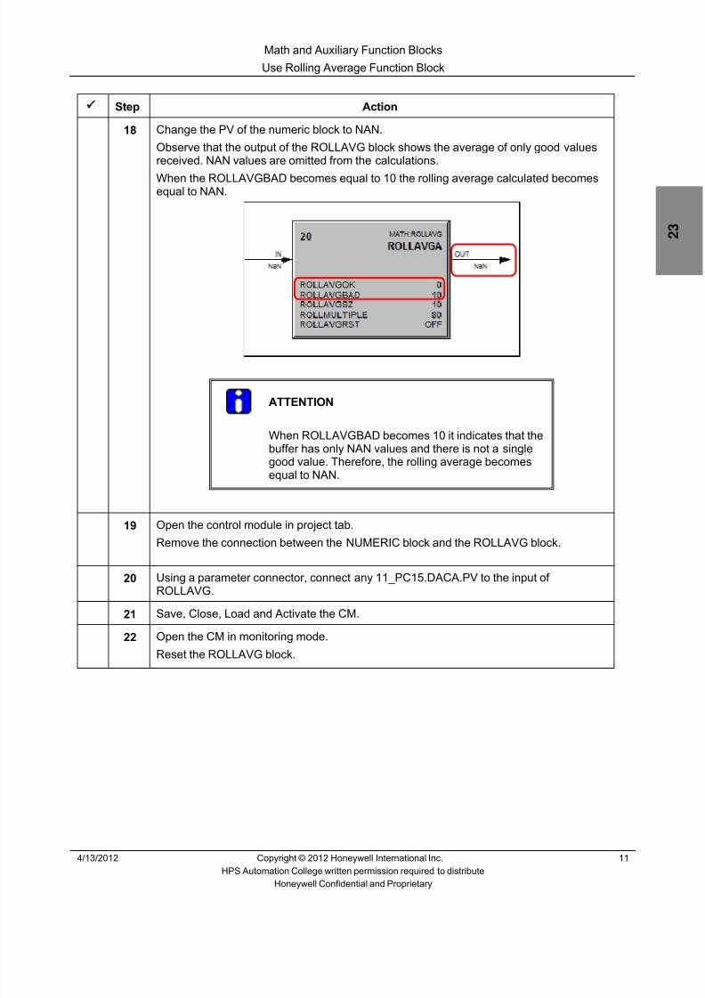
8/9/2019 Student Course Book- Automation
http://slidepdf.com/reader/full/student-course-book-automation 713/1165
Math and Auxiliary Function Blocks
Use Rolling Average Function Block
4/13/2012 Copyright © 2012 Honeywell International Inc. 11
HPS Automation College written permission required to distributeHoneywell Confidential and Proprietary
Step Action
18 Change the PV of the numeric block to NAN.
Observe that the output of the ROLLAVG block shows the average of only good valuesreceived. NAN values are omitted from the calculations.
When the ROLLAVGBAD becomes equal to 10 the rolling average calculated becomesequal to NAN.
ATTENTION
When ROLLAVGBAD becomes 10 it indicates that thebuffer has only NAN values and there is not a singlegood value. Therefore, the rolling average becomesequal to NAN.
19 Open the control module in project tab.Remove the connection between the NUMERIC block and the ROLLAVG block.
20 Using a parameter connector, connect any 11_PC15.DACA.PV to the input ofROLLAVG.
21 Save, Close, Load and Activate the CM.
22 Open the CM in monitoring mode.
Reset the ROLLAVG block.

8/9/2019 Student Course Book- Automation
http://slidepdf.com/reader/full/student-course-book-automation 714/1165
Math and Auxiliary Function Blocks
Use Rolling Average Function Block
12 Copyright © 2012 Honeywell International Inc. 4/13/2012
HPS Automation College written permission required to distributeHoneywell Confidential and Proprietary
Step Action
23 Observe the changes in the OUTPUT of ROLLAVG block.
In the example shown 11_TI21.DACA.PV is used.
ATTENTION
Make sure the TIE BACK excel sheet is running.
8/9/2019 Student Course Book- Automation
http://slidepdf.com/reader/full/student-course-book-automation 715/1165
Math and Auxiliary Function Blocks
Use Counter Function Block
4/13/2012 Copyright © 2012 Honeywell International Inc. 13
HPS Automation College written permission required to distributeHoneywell Confidential and Proprietary
Use Counter Function Block
Objective
• The objective of this lab is to configure and use the Counter function block
Prerequisites
• Knowledge of Configuration Studio.
• Knowledge of Control Builder and navigating through Control Builder
• Knowledge of configuring and loading the Control Modules
• C300/SIM-C300, C200E/SIM-C200E is created and loaded
TIP
The Counter block can’t be assigned to C200/SIM-C200 CEE.
Introduction
• At the conclusion of this lab, you will be able to do the following:
o Configure a counter function block
o Use the CNTUPFL,CNTDNFL,RESETFL,PAUSEFL,LOADFL flags

8/9/2019 Student Course Book- Automation
http://slidepdf.com/reader/full/student-course-book-automation 716/1165
Math and Auxiliary Function Blocks
Use Counter Function Block
14 Copyright © 2012 Honeywell International Inc. 4/13/2012
HPS Automation College written permission required to distributeHoneywell Confidential and Proprietary
o
Complete the following steps in Control Builder.
Step Action
1 Open Control Builder if it is not already opened.
2 Create a new Control Module with the following properties:
Tag Name: CM_Count
Item Name: CM_Count_Item
Description: CM for Counter
Parent Asset: < Any Existing Asset>
Click OK in the configuration properties and save the Control Module.
3 Save the Control Module and assign it to the CEE of SCE59 (or SIM-C300).
4 In the Library tree, expand the AUXILIARY library. Drag and drop a CTUD block onto theCM.
5 Double Click the CTUD block to open the block properties.
From the Block Pins Tab, remove the INFLOAT64 pin and add the ININT32 pin as an input onthe left.
6 From the Utility library, Drag and Drop the following blocks onto CM_Count:
FLAGARRAY
NUMERIC
TYPECONVERT
7 Double Click on FLAGARRAY to open the block properties.
On the Main tab, change the Number of Flag Values to 5.8 On the Block Pins Tab, add 5 PVFL pins as outputs on the right.

8/9/2019 Student Course Book- Automation
http://slidepdf.com/reader/full/student-course-book-automation 717/1165
Math and Auxiliary Function Blocks
Use Counter Function Block
4/13/2012 Copyright © 2012 Honeywell International Inc. 15
HPS Automation College written permission required to distributeHoneywell Confidential and Proprietary
Step Action
9 Arrange and Connect the blocks as shown below:
10 Double click the CTUDA block to open its configuration properties.

8/9/2019 Student Course Book- Automation
http://slidepdf.com/reader/full/student-course-book-automation 718/1165
Math and Auxiliary Function Blocks
Use Counter Function Block
16 Copyright © 2012 Honeywell International Inc. 4/13/2012
HPS Automation College written permission required to distributeHoneywell Confidential and Proprietary
Step Action
11 Enter the following in the configuration properties of the CTUD block:
Name: Counter
Description: Count Up or Down
Select the Count on Level Flag and Input Selection Specifier checkbox .
Leave other values to default and click OK.
TIP
If the Input Selection specifier is checked, then theinput format used in Counter block is INT32.If the Count on Level Flag is selected, then thecounter increments or decrements the value as leveltriggered quantities once every execution cycle.
12 Save and Close CM_Count.
13 Load and activate CM_Count .
14 In the Monitoring tab, open CM_Count.
15 Turn ON the PVFL[1] pin of the Flag array block which is connected to the CNTUPFL (CountUp Flag) pin.

8/9/2019 Student Course Book- Automation
http://slidepdf.com/reader/full/student-course-book-automation 719/1165
Math and Auxiliary Function Blocks
Use Counter Function Block
4/13/2012 Copyright © 2012 Honeywell International Inc. 17
HPS Automation College written permission required to distributeHoneywell Confidential and Proprietary
Step Action
16 Verify that the value of OUTINT32 is incremented once every execution cycle.
17 Turn on the PVFL[4] pin of the Flag Array block which is connected to PAUSEFL . ObserveOUTINT32 value is not getting incremented (or decremented ).
18 Turn off PVFL[4] pin of Flag Array block. Observe OUTINT32 value again starts incrementing.
19 Open the properties of the NUMERICA block. Enter 25 in the Actual Value column and pressenter. Click Yes in the Change Online Value dialog box.
20 Turn on PVFL[5] pin of the Flag Array block which is connected to LOADFL pin.
Verify that the value of OUTINT32 is changed to 25 and that QUFL is ON.
21 Turn off PVFL[5] pin of Flag Array block. Observe that OUTINT32 is incrementing and QUFL is still ON.
22 Turn off PVFL[1] pin of Flag Array block.
23 Turn on the PVFL[2] pin of the Flag Array block which is connected to CNTDNFL . Observethat OUTINT32 is getting decremented once every execution cycle.
Observe that QUFL is OFF.

8/9/2019 Student Course Book- Automation
http://slidepdf.com/reader/full/student-course-book-automation 720/1165
Math and Auxiliary Function Blocks
Use Counter Function Block
18 Copyright © 2012 Honeywell International Inc. 4/13/2012
HPS Automation College written permission required to distributeHoneywell Confidential and Proprietary
Step Action
24 When OUTINT32 value reaches 0 QDFL is ON.
25 Observe that OUTINT32 is decrementing and that QDFL is still ON.
26 Turn off the PVFL[2] pin of the Flag Array block.
27 Turn ON the PVFL[3] pin of the Flag Array block which is connected to RESETFL pin. Youwill observe that the value of OUTINT32 is set to 0.
28 Turn off the PVFL[3] pin .
29 Open the properties of the NUMERICA block and enter an actual value of 2147483645 .
Leave the other values to Default and click OK.

8/9/2019 Student Course Book- Automation
http://slidepdf.com/reader/full/student-course-book-automation 721/1165
Math and Auxiliary Function Blocks
Use Counter Function Block
4/13/2012 Copyright © 2012 Honeywell International Inc. 19
HPS Automation College written permission required to distributeHoneywell Confidential and Proprietary
Step Action
30 Turn ON the PVFL[5] pin of the Flag Array block which is connected to the LOADFL pin.Verify that the value of OUTINT32 was changed to 2147483645.
Turn off the PVFL[5] pin.
31 Turn ON the PVFL[1] pin of the Flag Array block connected to CNTUPLVL. When the value ofthe OUTINT32 crosses 2147483647, an overflow occurs and the counter value changes to-2,147,483,648 and continues counting .
TIP
Based on the value of the Counter Equation (CNTEQN) parameter, the Overflow and Underflowaction varies.For Equation C, if the Counter overflows from+2,147,483,647, OUTINT32 changes to 0
32 Turn OFF the PVFL[1] pin of the Flag Array block.

8/9/2019 Student Course Book- Automation
http://slidepdf.com/reader/full/student-course-book-automation 722/1165
Math and Auxiliary Function Blocks
Use Counter Function Block
20 Copyright © 2012 Honeywell International Inc. 4/13/2012
HPS Automation College written permission required to distributeHoneywell Confidential and Proprietary
Step Action
33 Close the CM_Count control module.

8/9/2019 Student Course Book- Automation
http://slidepdf.com/reader/full/student-course-book-automation 723/1165
1
1
Honeywell ConfidentialCopyright © 2012 Honeywell International Inc.
4/13/2012
Describe Search Functionality
Database Search Describe Search FunctionalityDatabase Search Describe Search Functionality
Honeywell
Honeywell ConfidentialCopyright © 2012 Honeywell International Inc.
4/13/20122
Introduction
• Search engine is embedded in Configuration Studio
• Search Utility is used to: – define the search criteria and initiate a search – search system databases, folders and files to determine where specific
strategies, templates, displays, and assets are used in the system – search for specific parameters that exist (defined) though they may not be
used – display detailed search results – save search criteria for future reference and use
Database Search Describe Search Functionality

8/9/2019 Student Course Book- Automation
http://slidepdf.com/reader/full/student-course-book-automation 724/1165
2
Honeywell
Honeywell ConfidentialCopyright © 2012 Honeywell International Inc.
4/13/20123
Search Types
• The Search Utility supportstwo query options: – Where Used – Parameter Search
• Search Utility provides theability to navigate betweenthese search options
Database Search Describe Search Functionality
Honeywell
Honeywell ConfidentialCopyright © 2012 Honeywell International Inc.
4/13/20124
System Search
• The Search Utility can be launched at either the system level, or theserver level – When launched as a system task, the search will allow one or all DSA
servers in the system to be searched – When launched as a server task, the search will allow only the connected
server to be searched
Database Search Describe Search Functionality

8/9/2019 Student Course Book- Automation
http://slidepdf.com/reader/full/student-course-book-automation 725/1165
3
Honeywell
Honeywell ConfidentialCopyright © 2012 Honeywell International Inc.
4/13/20125
Server Search
• Search scope covers the entire Experion System – The Search Utility supports searching Assets/Alarm Groups
• Search Utility, when launched as a Server task, will search the EMDB(assets / alarm groups), but will search the folders (displays), QDB(SCADA points), and ERDB (process points) only on the Server fromwhere it was launched
Database Search Describe Search Functionality
Honeywell
Honeywell ConfidentialCopyright © 2012 Honeywell International Inc.
4/13/20126
Where Used Search
• “Where Used” search option will list all the information regarding theusage of: – Control Strategies/Templates in the ERDB (project!) – HMIWeb Displays and shapes in the HMIWeb Display Builder files – Asset and Alarm Groups in the Enterprise Model Database (EMDB) – SCADA Points in the QDB
Database Search Describe Search Functionality

8/9/2019 Student Course Book- Automation
http://slidepdf.com/reader/full/student-course-book-automation 726/1165
4
Honeywell
Honeywell ConfidentialCopyright © 2012 Honeywell International Inc.
4/13/20127
Where Used Search - User Interface
Search Query Pane
Search Results Pane
Status Bar
Database Search Describe Search Functionality
Honeywell
Honeywell ConfidentialCopyright © 2012 Honeywell International Inc.
4/13/20128
Search Query Pane Options
New - Clears the “Search For” and “LookIn” fields
Load - Loads saved search criteriaSave - Saves the search criteria as an XML fileHelp - Launches a simpler version of
Knowledge Builder for search tips
Enter the object’s name to search for
Refines a search by defining searchcriteria (selecting specific data repositories andfile folders). Select double arrow for text inputboxes. A Browser Point Picker is available at
the right corner of all text input boxes
Launches a simpler version of KnowledgeBuilder with tips on how to search
Switch to Parameter Search
Database Search Describe Search Functionality

8/9/2019 Student Course Book- Automation
http://slidepdf.com/reader/full/student-course-book-automation 727/1165
5
Honeywell
Honeywell ConfidentialCopyright © 2012 Honeywell International Inc.
4/13/20129
Select Server Combobox
• Select the name of the Server(s) that will be searched when a searchquery is started – If the Search Utility is launched at the system level, the ‘Select Server’ drop-
down box will list all Servers that are configured in the Enterprise systemmodel
– When the Search Utility is launched at the Server level, the ‘Select Server’drop-down box will list only the Server that is currently connected toConfiguration Studio
Database Search Describe Search Functionality
Honeywell
Honeywell ConfidentialCopyright © 2012 Honeywell International Inc.
4/13/201210
Where Used Search – Default
• ‘Where Used’ search opens “All” search options by default
Database Search Describe Search Functionality

8/9/2019 Student Course Book- Automation
http://slidepdf.com/reader/full/student-course-book-automation 728/1165
6
Honeywell
Honeywell ConfidentialCopyright © 2012 Honeywell International Inc.
4/13/201211
Where Used Search – Specific Search
• An introductory Search Querypane is accessed when theBack button is selected in the“All” Search window – It also appears when “Where
Used” link is selected in the“Parameter” search query pane
• Where Used search has foursearch options: – Process Points – Display Shapes – Assets/Alarm Groups
– All/Any
Database Search Describe Search Functionality
Honeywell
Honeywell ConfidentialCopyright © 2012 Honeywell International Inc.
4/13/201212
Look In Options
Database Search Describe Search Functionality
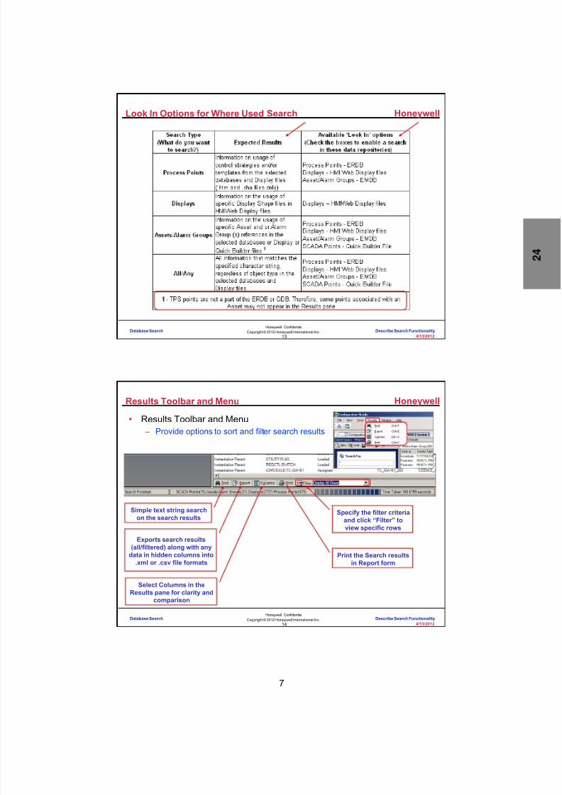
8/9/2019 Student Course Book- Automation
http://slidepdf.com/reader/full/student-course-book-automation 729/1165
7
Honeywell
Honeywell ConfidentialCopyright © 2012 Honeywell International Inc.
4/13/201213
Look In Options for Where Used Search
Database Search Describe Search Functionality
Honeywell
Honeywell ConfidentialCopyright © 2012 Honeywell International Inc.
4/13/201214
Results Toolbar and Menu
• Results Toolbar and Menu – Provide options to sort and filter search results
Simple text string searchon the search results
Specify the filter criteriaand click “Filter” toview specific rows
Exports search results(all/filtered) along with any
data in hidden columns into.xml or .csv file formats
Select Columns in theResults pane for clarity and
comparison
Print the Search resultsin Report form
Database Search Describe Search Functionality

8/9/2019 Student Course Book- Automation
http://slidepdf.com/reader/full/student-course-book-automation 730/1165
8
Honeywell
Honeywell ConfidentialCopyright © 2012 Honeywell International Inc.
4/13/201215
Where Used - Process Points
• Searches for usage of a given ControlStrategy/Template/Objects defined in theEngineering Repository Database (ERDB)
• Searches Process Point references inDisplay Files and Alarm groups
• The instances of data objects that aresearched includes usage as:
– a pin for a connection
– a block reference
• Instantiation, Derivation and Assignments offunction blocks and their parameters are
displayed in the results for a given strategy ortemplate when queried as ‘Where Used’
Database Search Describe Search Functionality
Honeywell
Honeywell ConfidentialCopyright © 2012 Honeywell International Inc.
4/13/201216
Where Used – Displays, Assets/Alarm Groups, All/Any
• Displays Shapes – Search for information on the usage of display shape references in Displays
and Shape files
• Assets/Alarm Groups
– Search for Asset and Alarm Group references defined in the Enterprise ModelDatabase (EMDB), ERDB, Display files and the Quick Builder file
• All/Any
– Search for data matching the text string specified in the ‘Search For’ textbox
Database Search Describe Search Functionality

8/9/2019 Student Course Book- Automation
http://slidepdf.com/reader/full/student-course-book-automation 731/1165
9
Honeywell
Honeywell ConfidentialCopyright © 2012 Honeywell International Inc.
4/13/201217
Parameter Search
• Search for Strategies/Templates based on Parameter names and values – Searches the ERDB and gets the information for all the Parameters with the
specified search criteria
Database Search Describe Search Functionality
Honeywell
Honeywell ConfidentialCopyright © 2012 Honeywell International Inc.
4/13/201218
Search Query Pane – Parameter Search
• Similar to “Where Used” Search Query Pane – Has only Process Points listed since
parameter query only searches the ERDB
– Advanced Option is used to add specificsearch criteria which helps refine the search
Database Search Describe Search Functionality

8/9/2019 Student Course Book- Automation
http://slidepdf.com/reader/full/student-course-book-automation 732/1165
10
Honeywell
Honeywell ConfidentialCopyright © 2012 Honeywell International Inc.
4/13/201219
Advanced Search Option
Used to define specific searchcriteria (explained later)
Search Criteria List Window
Conditions used to combineindividual criteria to form a
complex search option
Used to move/delete/clear thecriteria in the Search Criteria
List Window
Add the search criteria to
the Search Criteria ListWindow at the bottom
Database Search Describe Search Functionality
Honeywell
Honeywell ConfidentialCopyright © 2012 Honeywell International Inc.
4/13/201220
Advanced Option – Parameter Search
• “Field” Textbox: – Specifies a Parameter to be used by the search criteria
• A Browser Point Picker button is available to provide a list of parameters
• “Condition” Combobox: – Used to select specific conditions for the search criteria – Shows only valid options based on the parameter type (String, Boolean or
Other)
String --
Other --
Boolean --
Database Search Describe Search Functionality

8/9/2019 Student Course Book- Automation
http://slidepdf.com/reader/full/student-course-book-automation 733/1165
11
Honeywell
Honeywell ConfidentialCopyright © 2012 Honeywell International Inc.
4/13/201221
Advanced Option – Parameter Search
• “Value” Textbox: – Specify a valid value for the particular parameter type which is shown in the
‘Field’ textbox – Based on parameter type, a combobox or textbox will be available
• If parameter type is Boolean, the options are TRUE/FALSE – A combobox displays the appropriate options
• For Enumeration parameters, a combobox will list the appropriateenumeration values
• For other data types, an edit box is displayed where the value forcomparison is specified
Database Search Describe Search Functionality
Honeywell
Honeywell ConfidentialCopyright © 2012 Honeywell International Inc.
4/13/201222
Example – Parameter Search Results
• PVEUHI is searched for values between 80 and 110 – Search Results pane shows 74 points meet the specific search criteria
Database Search Describe Search Functionality

8/9/2019 Student Course Book- Automation
http://slidepdf.com/reader/full/student-course-book-automation 734/1165
12
Honeywell
Honeywell ConfidentialCopyright © 2012 Honeywell International Inc.
4/13/201223
Context Menu
• Search Results Pane
Database Search Describe Search Functionality
Honeywell
Honeywell ConfidentialCopyright © 2012 Honeywell International Inc.
4/13/201224
Wild Card Usage – Special Characters
• Wild card characters such as an asterisk ‘ ’ and question mark ‘?’ can beused in the Look In search option when specifying the item name – ‘*’ implies one or more characters where as “?” implies only a single
character
• Generic entries are supported as “Search” attributes – Examples used in search criteria: ex*, CM_?
• ex* will return search results ex1, ex2, example_cascade• CM_? will return search results CM_1, CM_2, CM_A (single character
replacement)
Database Search Describe Search Functionality
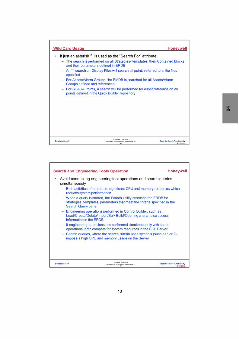
8/9/2019 Student Course Book- Automation
http://slidepdf.com/reader/full/student-course-book-automation 735/1165
13
Honeywell
Honeywell ConfidentialCopyright © 2012 Honeywell International Inc.
4/13/201225
Wild Card Usage
• If just an asterisk ‘ ’ is used as the “Search For” attribute: – The search is performed on all Strategies/Templates, their Contained Blocks
and their parameters defined in ERDB – An ‘*’ search on Display Files will search all points referred to in the files
specified – For Assets/Alarm Groups, the EMDB is searched for all Assets/Alarm
Groups defined and referenced – For SCADA Points, a search will be performed for Asset reference on all
points defined in the Quick Builder repository
Database Search Describe Search Functionality
Honeywell
Honeywell ConfidentialCopyright © 2012 Honeywell International Inc.
4/13/201226
Search and Engineering Tools Operation
• Avoid conducting engineering tool operations and search queriessimultaneously – Both activities often require significant CPU and memory resources which
reduces system performance – When a query is started, the Search Utility searches the ERDB for
strategies, templates, parameters that meet the criteria specified in theSearch Query pane
– Engineering operations performed in Control Builder, such asLoad/Create/Delete/Import/Bulk Build/Opening charts, also accessinformation in the ERDB
– If engineering operations are performed simultaneously with searchoperations, both compete for system resources in the SQL Server
– Search queries, where the search criteria uses symbols (such as * or ?),impose a high CPU and memory usage on the Server
Database Search Describe Search Functionality
8/9/2019 Student Course Book- Automation
http://slidepdf.com/reader/full/student-course-book-automation 736/1165
14
Honeywell
Honeywell ConfidentialCopyright © 2012 Honeywell International Inc.
4/13/201227
Multiple Instance of Search Utility
• Each Configuration Studio instance (on the same or different Servers): – Creates a separate instance of the Search Utility – Can create multiple instances of the Search Utility when launched at the
System level
• One instance of the Search Utility may be opened for the System and foreach configured Server in Configuration Studio
• Note: – Parameter Search and Where Used search cannot be simultaneously
performed on the same Server when connected at the Server level – Either a Parameter or Where Used search may be performed at the Server
level while a different search can be performed on the same Server byconnecting at the System level
Database Search Describe Search Functionality
Honeywell
Honeywell ConfidentialCopyright © 2012 Honeywell International Inc.
4/13/201228
Conclusion
Describe Search Functionality
CompletionCertificate
Proceed to the Perform Parameter Search lab exercise.
Database Search Describe Search Functionality

8/9/2019 Student Course Book- Automation
http://slidepdf.com/reader/full/student-course-book-automation 737/1165
4/13/2012 Copyright © 2012 Honeywell International Inc. 1
HPS Automation College written permission required to distributeHoneywell Confidential and Proprietary
Topic: Database Search
Contents
Perform Parameter Search .................................................................................................................... 3
Perform Where Used Search ................................................................ ................................................ 9

8/9/2019 Student Course Book- Automation
http://slidepdf.com/reader/full/student-course-book-automation 738/1165
2 Copyright © 2012 Honeywell International Inc. 4/13/2012
HPS Automation College written permission required to distributeHoneywell Confidential and Proprietary
This page was intentionally left blank.

8/9/2019 Student Course Book- Automation
http://slidepdf.com/reader/full/student-course-book-automation 739/1165
Database Search
Perform Parameter Search
4/13/2012 Copyright © 2012 Honeywell International Inc. 3
HPS Automation College written permission required to distributeHoneywell Confidential and Proprietary
Perform Parameter Search
Practice
Objective
After completing this lesson you will be able to search for parameters using the ‘Parameter Search’function.
Introduction
The purpose of this lesson is to familiarize you about the usage of Parameter Search inConfiguration Studio

8/9/2019 Student Course Book- Automation
http://slidepdf.com/reader/full/student-course-book-automation 740/1165
Database Search
Perform Parameter Search
4 Copyright © 2012 Honeywell International Inc. 4/13/2012
HPS Automation College written permission required to distributeHoneywell Confidential and Proprietary
Step Action
1 Open Configuration studio if not already open. Select Your Server . Select Search for aparameter in the system (Parameter Search) from the Search heading
2In the Search For Parameter text box, click on the Point picker button.

8/9/2019 Student Course Book- Automation
http://slidepdf.com/reader/full/student-course-book-automation 741/1165
Database Search
Perform Parameter Search
4/13/2012 Copyright © 2012 Honeywell International Inc. 5
HPS Automation College written permission required to distributeHoneywell Confidential and Proprietary
Step Action
3 In the ‘Browser Point Picker’ dialog box, select PVEUHI (High Range in EUs) parameterand click OK .
4 Display the Advanced options by clicking on the double arrow .
5In the Advanced options, click on the Point picker button, select PVEUHI (HighRange in EUs) parameter, and click OK .
6 In the Advanced options, click on the Condition drop down list (just to the right of thepoint picker).

8/9/2019 Student Course Book- Automation
http://slidepdf.com/reader/full/student-course-book-automation 742/1165
Database Search
Perform Parameter Search
6 Copyright © 2012 Honeywell International Inc. 4/13/2012
HPS Automation College written permission required to distributeHoneywell Confidential and Proprietary
Step Action
7 In the ‘Select Parameter’ dialog box, select PVEUHI (High Range in EUs) – 64 bit parameter, and click Select .
8 In the Condition Combo Box, select >=
ATTENTION
The last few steps may need to be repeated to makethe Condition Combo Box display the >= selection.
9 Click in the Value combo box (to move your cursor into the field) and enter 90 into thetext box.

8/9/2019 Student Course Book- Automation
http://slidepdf.com/reader/full/student-course-book-automation 743/1165
Database Search
Perform Parameter Search
4/13/2012 Copyright © 2012 Honeywell International Inc. 7
HPS Automation College written permission required to distributeHoneywell Confidential and Proprietary
Step Action
10 Click the Add button. The Search Criteria List window shows the criteria which isadded.
11 Click the AND operator and repeat the steps above to add a criteria PVEUHI <= 110 .
ATTENTION
Be sure to make this condition <= (less than or equal),and make sure the value entered is 110 . Therefore,the condition will be PVEUHI <= 110.
12 Click on the Search button.

8/9/2019 Student Course Book- Automation
http://slidepdf.com/reader/full/student-course-book-automation 744/1165
Database Search
Perform Parameter Search
8 Copyright © 2012 Honeywell International Inc. 4/13/2012
HPS Automation College written permission required to distributeHoneywell Confidential and Proprietary
Step Action
13 The Search Results Pane lists Control Strategies and Templates in the ERDB whichhave a PVEUHI parameter value between 90 and 110
14 Look on the status bar (at the bottom of the window) for the status of the search, thenumber of points found, and the time taken to do the search.

8/9/2019 Student Course Book- Automation
http://slidepdf.com/reader/full/student-course-book-automation 745/1165
Database Search
Perform Where Used Search
4/13/2012 Copyright © 2012 Honeywell International Inc. 9
HPS Automation College written permission required to distributeHoneywell Confidential and Proprietary
Perform Where Used Search
Practice
Objective
After completing this lesson you will be able to search for a point using the Where Used search
Introduction
The purpose of this lesson is to familiarize you about the usage of the Where Used search inConfiguration Studio

8/9/2019 Student Course Book- Automation
http://slidepdf.com/reader/full/student-course-book-automation 746/1165
Database Search
Perform Where Used Search
10 Copyright © 2012 Honeywell International Inc. 4/13/2012
HPS Automation College written permission required to distributeHoneywell Confidential and Proprietary
Step Action
1 Launch Configuration Studio, connect to your system , and provide credentials of a userwith mngr security level.
2 In the Tree pane (left side), select your system. Click on the task Determine where anobject is used in the system (Where Used) .
3 Type 11_FC01 in the ‘Search For’ text box.
4 Expand Displays by selecting the double arrow next to the Displays option.

8/9/2019 Student Course Book- Automation
http://slidepdf.com/reader/full/student-course-book-automation 747/1165
Database Search
Perform Where Used Search
4/13/2012 Copyright © 2012 Honeywell International Inc. 11
HPS Automation College written permission required to distributeHoneywell Confidential and Proprietary
Step Action
5 Select the Point picker in the text box, expand items, check the DisplayShare2 option(path) and click OK.
6 Click the Search button.

8/9/2019 Student Course Book- Automation
http://slidepdf.com/reader/full/student-course-book-automation 748/1165
Database Search
Perform Where Used Search
12 Copyright © 2012 Honeywell International Inc. 4/13/2012
HPS Automation College written permission required to distributeHoneywell Confidential and Proprietary
Step Action
7 The Search Results Pane lists the usage of 11_FC01 in Process points, Displays and Asset / Alarm Groups
ATTENTION
Search will take some time based upon your databasesize
8 Look on the status bar for information about the search (including the status of thesearch).
9 View both the Displays tab and the Process Points tab.

8/9/2019 Student Course Book- Automation
http://slidepdf.com/reader/full/student-course-book-automation 749/1165
1
1
Honeywell ConfidentialCopyright © 2012 Honeywell International Inc.
4/13/2012
Describe the Configuration of SCMs
Sequential Control Module - Concepts and Use Describe the Configuration of SCMsSequential Control Module - Concepts and Use Describe the Configuration of SCMs
Honeywell
Honeywell ConfidentialCopyright © 2012 Honeywell International Inc.
4/13/20122
Introduction
• In this lesson you will learn about sequential control modules (SCMs).
• At the conclusion of this lesson, you will be able to:
– Build and edit SCMs
– Configure transition andstep function blocks
– Configure step timing
Sequential Control Module - Concepts and Use Describe the Configuration of SCMs

8/9/2019 Student Course Book- Automation
http://slidepdf.com/reader/full/student-course-book-automation 750/1165
2
Honeywell
Honeywell ConfidentialCopyright © 2012 Honeywell International Inc.
4/13/20123
Introduction• SCMs:
– Provide phase-level batch functionality
– Command regulatory and discrete function blocks, contained within controlmodules in a defined order, to accomplish higher-level tasks (for example,boiler startup).
– Contain the following function blocks:
• Transitions that determine when to proceed
• Steps that take action
• Handlers for specified exceptions
• Synchronization for parallel execution
Sequential Control Module - Concepts and Use Describe the Configuration of SCMs
Honeywell
Honeywell ConfidentialCopyright © 2012 Honeywell International Inc.
4/13/20124
Topics
• Rules for Building SCMs
• SCM Transitions
• SCM Steps
• Step Timing and Configuration
• SCM Code Examples
Sequential Control Module - Concepts and Use Describe the Configuration of SCMs

8/9/2019 Student Course Book- Automation
http://slidepdf.com/reader/full/student-course-book-automation 751/1165
3
Honeywell
Honeywell ConfidentialCopyright © 2012 Honeywell International Inc.
4/13/20125
Sequential Control Modules - Rules
• Rule 1 – Every SCM begins with an Invoke Transition.
Sequential Control Module - Concepts and Use Describe the Configuration of SCMs
Honeywell
Honeywell ConfidentialCopyright © 2012 Honeywell International Inc.
4/13/20126
Sequential Control Modules - Rules
• Rule 2 – SCMs can have multiple endings.
Candy Step
Ship It AddChocolate
Add GrapeFlavor
END END END
Sequential Control Module - Concepts and Use Describe the Configuration of SCMs

8/9/2019 Student Course Book- Automation
http://slidepdf.com/reader/full/student-course-book-automation 752/1165
4
Honeywell
Honeywell ConfidentialCopyright © 2012 Honeywell International Inc.
4/13/20127
Sequential Control Modules - Rules
• Rule 3 – Generally logic shall be made with Transitions and Steps in
alternate in SCM; however,• Step to Step connection is allowed in SCMs in R300 and later.• Transition to Transition Connections are still NOT allowed.
Red “ !” whenactivated indicates
an error (This is Elaborated
in the next slide)
Sequential Control Module - Concepts and Use Describe the Configuration of SCMs
Honeywell
Honeywell ConfidentialCopyright © 2012 Honeywell International Inc.
4/13/20128
Sequential Control Modules - Rules
A Failed SCM is indicated by a red “ !”
The error exists at the start of main. Here theINVOKE MAIN TRANSITION block is missing
Steps and Transitions areshown in alphabeticalorder, not in “flow” orexecution order.
Sequential Control Module - Concepts and Use Describe the Configuration of SCMs

8/9/2019 Student Course Book- Automation
http://slidepdf.com/reader/full/student-course-book-automation 753/1165
5
Honeywell
Honeywell ConfidentialCopyright © 2012 Honeywell International Inc.
4/13/20129
Sequential Control Modules - Rules
A SCM with a severe warning is indicatedby a blue “ !”
The error exists within main
A TRANSITION block to a TRANSITIONblock connection is not allowed, even witha SYNC block acting as an Intermediary.
In this case, execution of the SCMwill stop at the first of the twotransitions and will not continue –
even if all conditions are true.
Ex: Transition configured with onlyone condition, but several Primarygates.
Sequential Control Module - Concepts and Use Describe the Configuration of SCMs
Honeywell
Honeywell ConfidentialCopyright © 2012 Honeywell International Inc.
4/13/201210
Sequential Control Modules - Rules
An SCM with a normal warning isindicated by an inverted “ !”
The error is within main, andrepresents either a Transition
condition or a Step output failure
Sequential Control Module - Concepts and Use Describe the Configuration of SCMs

8/9/2019 Student Course Book- Automation
http://slidepdf.com/reader/full/student-course-book-automation 754/1165
6
Honeywell
Honeywell ConfidentialCopyright © 2012 Honeywell International Inc.
4/13/201211
Sequential Control Modules - Example
Transition
Step
Sequential Control Module - Concepts and Use Describe the Configuration of SCMs
Honeywell
Honeywell ConfidentialCopyright © 2012 Honeywell International Inc.
4/13/201212
Question 1: Building an SCM
Incorrect. SCMs begin with invoketransitions.
Click anywhere to continue.
Incorrect. SCMs begin with invoketransitions.
Click anywhere to continue.
Correct! SCMs begin with invoketransitions.
Click anywhere to continue.
Incorrect. SCMs begin with invoketransitions.
Click anywhere to continue.
Correct - Click anywhere to continueIncorrect - Click anywhere to continueYou answered this correctly!
Your answer: The correct answer is:
You did not answer this question completelyYou must answer the question beforecontinuing
Submit Clear
An SCM begins with:
A) A project identification number
B) An END statement
C) An invoke transition
D) A transition
Sequential Control Module - Concepts and Use Describe the Configuration of SCMs

8/9/2019 Student Course Book- Automation
http://slidepdf.com/reader/full/student-course-book-automation 755/1165
7
Honeywell
Honeywell ConfidentialCopyright © 2012 Honeywell International Inc.
4/13/201213
Topics
• Rules for Building SCMs
• SCM Transitions
• SCM Steps
• Step Timing and Configuration
• SCM Code Examples
Sequential Control Module - Concepts and Use Describe the Configuration of SCMs
Honeywell
Honeywell ConfidentialCopyright © 2012 Honeywell International Inc.
4/13/201214
Sequential Control Modules - Transitions
• Transitions:
– Evaluate if the sequential control module is ready to advance to the nextstep
– Ask questions
• You can define:
– Up to 10 conditions per transition
– 4 logic gates per transition
• 3 primary
• 1 secondary
?
LogicGates
Sequential Control Module - Concepts and Use Describe the Configuration of SCMs

8/9/2019 Student Course Book- Automation
http://slidepdf.com/reader/full/student-course-book-automation 756/1165
8
Honeywell
Honeywell ConfidentialCopyright © 2012 Honeywell International Inc.
4/13/201215
Transitions determine when to proceed
Sequential Control Modules - Transitions
Selectable Transition conditiondescriptions
Sequential Control Module - Concepts and Use Describe the Configuration of SCMs
Honeywell
Honeywell ConfidentialCopyright © 2012 Honeywell International Inc.
4/13/201216
Sequential Control Modules - Transitions
Transition conditions(code)
Sequential Control Module - Concepts and Use Describe the Configuration of SCMs

8/9/2019 Student Course Book- Automation
http://slidepdf.com/reader/full/student-course-book-automation 757/1165
9
Honeywell
Honeywell ConfidentialCopyright © 2012 Honeywell International Inc.
4/13/201217
Fetch Enumeration
• Some of the parameter values used in SCM Condition and Output
expressions require enumeration – Enumeration is a set of numbers corresponding to the parameter values – For example, the Mode parameter has an enumerated value set of 0 to 5
representing the possible modes
SelectPoint.Parameter
ClickFetch Enums
Drop down displays thepossible Enumeration
for selectedpoint.parameter
Sequential Control Module - Concepts and Use Describe the Configuration of SCMs
Honeywell
Honeywell ConfidentialCopyright © 2012 Honeywell International Inc.
4/13/201218
Why Use Fetch Enums?
• Data type for all enumerated parameters used in Condition and Outputexpressions is numeric – Hence it is necessary to enter a specific number corresponding to the
specific parameter state
– For example• For Mode parameter
– MAN (0) – AUTO (1) – CAS (2) – BCAS (3) – None (4)
– Normal (5)
Sequential Control Module - Concepts and Use Describe the Configuration of SCMs

8/9/2019 Student Course Book- Automation
http://slidepdf.com/reader/full/student-course-book-automation 758/1165
10
Honeywell
Honeywell ConfidentialCopyright © 2012 Honeywell International Inc.
4/13/201219
Topics
• Rules for Building SCMs
• SCM Transitions
• SCM Steps
• Step Timing and Configuration
• SCM Code Examples
Sequential Control Module - Concepts and Use Describe the Configuration of SCMs
Honeywell
Honeywell ConfidentialCopyright © 2012 Honeywell International Inc.
4/13/201220
Sequential Control Modules - Steps
• Steps perform actions and send output commands to control modulefunction blocks
• Note: the control module’s mode attribute must be “Program”
• You can define up to 16 individual outputs/actions per step
• Minimum and maximum wait times are supported
Sequential Control Module - Concepts and Use Describe the Configuration of SCMs

8/9/2019 Student Course Book- Automation
http://slidepdf.com/reader/full/student-course-book-automation 759/1165
11
Honeywell
Honeywell ConfidentialCopyright © 2012 Honeywell International Inc.
4/13/201221
Steps take actions
Sequential Control Modules - Steps
Selectable Step outputdescriptions
Sequential Control Module - Concepts and Use Describe the Configuration of SCMs
Honeywell
Honeywell ConfidentialCopyright © 2012 Honeywell International Inc.
4/13/201222
Sequential Control Modules - Steps
Step outputs(code)
Sequential Control Module - Concepts and Use Describe the Configuration of SCMs

8/9/2019 Student Course Book- Automation
http://slidepdf.com/reader/full/student-course-book-automation 760/1165
12
Honeywell
Honeywell ConfidentialCopyright © 2012 Honeywell International Inc.
4/13/201223
Question 2: Transition vs. Steps
Correct - Click anywhere to continueIncorrect - Click anywhere to continueYou answered this correctly!
Your answer:The correct answer is:
You did not answer this question completelyYou must answer the question beforecontinuing
Submit Clear
Incorrect! Generally, Transitions and Steps are toalternate within the SCM. However, in Experion
Release 300, step to step connection is allowed. But
transition to transition connections are still NOTallowed.
Click anywhere to continue.
Correct! Generally, Transitions and Steps are toalternate within the SCM. However, in Experion
Release 300, step to step connection is allowed. But
transition to transition connections are still NOTallowed.
Click anywhere to continue.
Incorrect! Generally, Transitions and Steps are toalternate within the SCM. However, in Experion
Release 300, step to step connection is allowed. But
transition to transition connections are still NOTallowed.
Click anywhere to continue.
Incorrect! Generally, Transitions and Steps are toalternate within the SCM. However, in Experion
Release 300, step to step connection is allowed. But
transition to transition connections are still NOTallowed.
Click anywhere to continue.
Transitions and Steps:
A) Are identical to PID function blocks
B) Generally alternate in an SCM, ifrequired, Step to Step connectionis valid
C) Cannot be used in an SCM
D) Are built using Quick Builder
Sequential Control Module - Concepts and Use Describe the Configuration of SCMs
Honeywell
Honeywell ConfidentialCopyright © 2012 Honeywell International Inc.
4/13/201224
Topics
• Rules for Building SCMs
• SCM Transitions
• SCM Steps
• Step Timing and Configuration
• SCM Code Examples
Sequential Control Module - Concepts and Use Describe the Configuration of SCMs

8/9/2019 Student Course Book- Automation
http://slidepdf.com/reader/full/student-course-book-automation 761/1165
13
Honeywell
Honeywell ConfidentialCopyright © 2012 Honeywell International Inc.
4/13/201225
Sequential Control Modules – Step Timing
• Min Wait Time (in execution periods) – Specifies how long to delay evaluation of succeeding Transition block after
step outputs are stored. If Execution period is 50 milliseconds and Min WaitTime is 100, the start of succeeding Transition is delayed by 5000 ms (5 s)
• Max Active Time – The maximum number of execution periods that the steps can be active
before an SCM Step Alarm is generated• Configure the alarm priority on the SCM properties, not on the individual
step output properties
MinimumWait Time
Maximum Active Time
The step timer beginswhen the execution ofthe step begins.
Sequential Control Module - Concepts and Use Describe the Configuration of SCMs
Honeywell
Honeywell ConfidentialCopyright © 2012 Honeywell International Inc.
4/13/201226
Sequential Control Modules – Step Timing
Enter times in number of execution periods.Ex: An entry of 600is = 300 seconds(exec. per. = 500ms)
Sequential Control Module - Concepts and Use Describe the Configuration of SCMs

8/9/2019 Student Course Book- Automation
http://slidepdf.com/reader/full/student-course-book-automation 762/1165
14
Honeywell
Honeywell ConfidentialCopyright © 2012 Honeywell International Inc.
4/13/201227
STEP Expression – DELAY
• DELAY is the period, in seconds, for which the output will pause beforeits expression execution – ie. before processing this output – Value is rounded up to the next multiple of the SCM period
• For example with an SCM PERIOD of 10 secs, a value of 15 stored toOP(i).DELAYTIME will be rounded up to 20
– Value range is 0 to 25000000 seconds – Only applicable to Automatic outputs that have expressions configured – If a non-zero Step Output Delay time is entered for an Output with only an
instruction, the delay time will have no effect
A Step’s active time should not be smaller than the largest output Delay
Sequential Control Module - Concepts and Use Describe the Configuration of SCMs
Honeywell
Honeywell ConfidentialCopyright © 2012 Honeywell International Inc.
4/13/201228
Difference between ‘=’ and ‘:=’ in an SCM
• Transition block is used to evaluate if a SCM is ready to advance to thenext step – ‘:=‘ is not supported in Transition condition expressions – ‘=‘ is used to compare or evaluate that a condition has been met or satisfied
• STEP block performs actions and sends output commands to ControlModule function blocks – ‘:=‘ is used to set the value of a point parameter – ‘=‘ is not supported in STEP output expressions
Sequential Control Module - Concepts and Use Describe the Configuration of SCMs

8/9/2019 Student Course Book- Automation
http://slidepdf.com/reader/full/student-course-book-automation 763/1165
15
Honeywell
Honeywell ConfidentialCopyright © 2012 Honeywell International Inc.
4/13/201229
Topics
• Rules for Building SCMs
• SCM Transitions
• SCM Steps
• Step Timing and Configuration
• SCM Code Examples
Sequential Control Module - Concepts and Use Describe the Configuration of SCMs
30
Honeywell ConfidentialCopyright © 2012 Honeywell International Inc.
4/13/2012
Commanding DeviceControl Block outputs from
SCMs
Sequential Control Module - Concepts and Use Describe the Configuration of SCMs

8/9/2019 Student Course Book- Automation
http://slidepdf.com/reader/full/student-course-book-automation 764/1165
16
Honeywell
Honeywell ConfidentialCopyright © 2012 Honeywell International Inc.
4/13/201231
Using Logic and Override/Interlocks
Logic and Override/Interlocks wereused to drive the Device Controlblock output in the course labs – asin the case of the templateFANLOGICIn a simple example:
An SCM could write to a flag in thelogic which could assert anOverride/Interlock forcing the outputto the associated state.
The following slides show several other methods for an SCM tocommand Device
Control Module outputs:1) Generic OP – GOP2) Output Command - OPCMD
Sequential Control Module - Concepts and Use Describe the Configuration of SCMs
Honeywell
Honeywell ConfidentialCopyright © 2012 Honeywell International Inc.
4/13/201232
Generic OP - GOP
The SCM writes to the GOP parameter on the device control block.This is the most commonly used device control command• Pros
– Simple direct programming of devices allowing flexible easy to understanddesigns
• Cons – Programming must be structured to prevent step output failures for device
control blocks with Override/Interlocks asserted or in Operator MODEATTR
Sequential Control Module - Concepts and Use Describe the Configuration of SCMs

8/9/2019 Student Course Book- Automation
http://slidepdf.com/reader/full/student-course-book-automation 765/1165
17
Honeywell
Honeywell ConfidentialCopyright © 2012 Honeywell International Inc.
4/13/201233
Output Command - OPCMD
Output command parameters OPCMD[0..2] on the device control block canbe commanded directly from an SCM.
• Pros – SCM writes to a flag (logic associated with the device control block) – Commanding a device with an active interlock will not cause an SCM failure – Commanding a device in operator MODEATTR will not cause a failure
• Cons – Requires logic associated with the device control block (see next slide) – Action upon transition to Program or interlock clear will not always be apparent
and may be confusing for operators: – Device will return to the last requested state on interlock clear – The last requested state will be executed when the device control block
MODEATTR is set to Program
Sequential Control Module - Concepts and Use Describe the Configuration of SCMs
Honeywell
Honeywell ConfidentialCopyright © 2012 Honeywell International Inc.
4/13/201234
Common Device CM Configuration
Sequential Control Module - Concepts and Use Describe the Configuration of SCMs

8/9/2019 Student Course Book- Automation
http://slidepdf.com/reader/full/student-course-book-automation 766/1165
18
Honeywell
Honeywell ConfidentialCopyright © 2012 Honeywell International Inc.
4/13/201235
Additional Code Examples
• 11_AC12.PIDA.SP:=SCM_D100 .RECTARGET[3]
• MESSAGES.XFERB.SENDFL[3] := 1
• 11_PC15.PIDA.SP := (1050.0 - (11_PC15.PIDA.PVEUHI -11_PC15.PIDA.PVEULO) * (FLAGS.FLOW.PV/100.0)) +11_PC15.PIDA.PVEULO
• 11_PC15.PIDA.SP:=(SCM_D100.RECTARGET[2]+700)
• CM456.PIDA.SP := (CM456.SPREC1FLAG.PVFL) ?SCM457.RECTARGET[1] : NOP
If / ThenNo Operation(do nothing)
Sequential Control Module - Concepts and Use Describe the Configuration of SCMs
Honeywell
Honeywell ConfidentialCopyright © 2012 Honeywell International Inc.
4/13/201236
SCM State Change Diagram
IDLE
RUNNING
INACTIVE(1st State After Download)
VALIDATED
START
ABORTED ABORT
RESET
HELD
ABORT
COMPLETE
INTERRUPTING
INTERRUPT
RESET
INACTIVE ACTIVE
STOPPED
STOP
HOLDSTOP
HOLD RESTART
RESET
RESUME
ABORT RESET
Sequential Control Module - Concepts and Use Describe the Configuration of SCMs
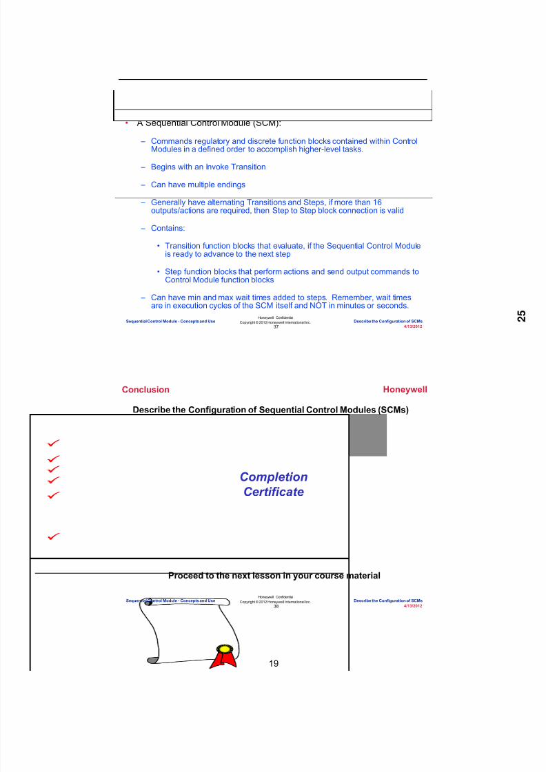
8/9/2019 Student Course Book- Automation
http://slidepdf.com/reader/full/student-course-book-automation 767/1165
19
Honeywell
Honeywell ConfidentialCopyright © 2012 Honeywell International Inc.
4/13/201237
Summary
• A Sequential Control Module (SCM):
– Commands regulatory and discrete function blocks contained within ControlModules in a defined order to accomplish higher-level tasks.
– Begins with an Invoke Transition
– Can have multiple endings
– Generally have alternating Transitions and Steps, if more than 16outputs/actions are required, then Step to Step block connection is valid
– Contains:
• Transition function blocks that evaluate, if the Sequential Control Moduleis ready to advance to the next step
• Step function blocks that perform actions and send output commands toControl Module function blocks
– Can have min and max wait times added to steps. Remember, wait timesare in execution cycles of the SCM itself and NOT in minutes or seconds.
Sequential Control Module - Concepts and Use Describe the Configuration of SCMs
Honeywell
Honeywell ConfidentialCopyright © 2012 Honeywell International Inc.
4/13/201238
Conclusion
Describe the Configuration of Sequential Control Modules (SCMs)
CompletionCertificate
Proceed to the next lesson in your course material
Sequential Control Module - Concepts and Use Describe the Configuration of SCMs

8/9/2019 Student Course Book- Automation
http://slidepdf.com/reader/full/student-course-book-automation 768/1165
Copyright © 201 2 Honeywell International Inc.
HPS Automation College written permission required to distributeHoneywell Confidential and Proprietary
This page was intentionally left blank.

8/9/2019 Student Course Book- Automation
http://slidepdf.com/reader/full/student-course-book-automation 769/1165
4/13/2012 Copyright © 2012 Honeywell International Inc. 1
HPS Automation College written permission required to distributeHoneywell Confidential and Proprietary
Topic: Sequential Control Module - Concepts and Use
Contents
Configure a Sequential Control Module ................................................................................................. 3

8/9/2019 Student Course Book- Automation
http://slidepdf.com/reader/full/student-course-book-automation 770/1165
2 Copyright © 2012 Honeywell International Inc. 4/13/2012
HPS Automation College written permission required to distributeHoneywell Confidential and Proprietary
This page was intentionally left blank.

8/9/2019 Student Course Book- Automation
http://slidepdf.com/reader/full/student-course-book-automation 771/1165
Sequential Control Module - Concepts and Use
Configure a Sequential Control Module
4/13/2012 Copyright © 2012 Honeywell International Inc. 3
HPS Automation College written permission required to distributeHoneywell Confidential and Proprietary
Configure a Sequential Control Module
Objectives
• Create an SCM
• Configure SCM components
• Download an SCM to the controller
• Monitor an SCM online
Prerequisites
• Experion PKS Server with Configuration Studio installed• Debutanizer_123.htm graphic loaded on the Server (This is required at a later time to check
the control strategy.)
• Excel Data Exchange open with the simulation spread sheet open• All the previously built points loaded and active
Introduction
The requirement is to pressurize the Debutanizer T100 tower at startup prior to starting the feed.The fans of the heat exchanger are started and the feed begun.
• Open HC44, PC15, and PC16, and back pressure the debutanizer (PI14) with natural gasimported from the compressor interstage drum.
• When the tower is pressurized, the following steps are completed:
1. Set bypass HC44 valve to 20 percent2. Set PC15 at 1240 kPag and PC16 at 1170 kPag in automatic3. Send the following message to the Operator:
Pressure stabilization SCM complete
• A CM named FLAGS needs to be built to facilitate the operation of the SCM. The followingCMs and SCMs will be built in this lab:
NAME Action to be taken
CM > FLAGS Configure 3 Flag blocks and one
Message block to facilitate the SCMoperation.
SCM > SCM_Pressure Configure step sequences, to operate11_HC44, 11_PC15 and 11_PC16 topressurize the T-100 tower, beforestarting the feed.

8/9/2019 Student Course Book- Automation
http://slidepdf.com/reader/full/student-course-book-automation 772/1165
Sequential Control Module - Concepts and Use
Configure a Sequential Control Module
4 Copyright © 2012 Honeywell International Inc. 4/13/2012
HPS Automation College written permission required to distributeHoneywell Confidential and Proprietary
Perform the following steps in Control Builder.
Create a SCM
Step Action
1 Build a new CM named FLAGS and assign it to your CEE.
Drag a Control Module from the Library tab to the CEE in the Project tab .

8/9/2019 Student Course Book- Automation
http://slidepdf.com/reader/full/student-course-book-automation 773/1165
Sequential Control Module - Concepts and Use
Configure a Sequential Control Module
4/13/2012 Copyright © 2012 Honeywell International Inc. 5
HPS Automation College written permission required to distributeHoneywell Confidential and Proprietary
Step Action
2 Enter FLAGS in the Destination field as shown below.
Click Finish .
3 Find the Flags CM in the Project tree and double-click it to open in chart
view.Double-click anywhere on the blank background to open the CMproperties.
On the Main tab, enter the information as follows:
Name: FLAGS
Item Name: FLAGS_Item
Parent Asset C11
Leave all other entries as default.
Click OK .

8/9/2019 Student Course Book- Automation
http://slidepdf.com/reader/full/student-course-book-automation 774/1165
Sequential Control Module - Concepts and Use
Configure a Sequential Control Module
6 Copyright © 2012 Honeywell International Inc. 4/13/2012
HPS Automation College written permission required to distributeHoneywell Confidential and Proprietary
Step Action
4 Add a Flag function block to this CM.
Expand the Utility block in the Library tree window, and select the FLAG block,as shown below.
Drag the FLAG block to the FLAGS chart window, which is open.

8/9/2019 Student Course Book- Automation
http://slidepdf.com/reader/full/student-course-book-automation 775/1165
Sequential Control Module - Concepts and Use
Configure a Sequential Control Module
4/13/2012 Copyright © 2012 Honeywell International Inc. 7
HPS Automation College written permission required to distributeHoneywell Confidential and Proprietary
Step Action
5 Double-click the FLAGA block to open the configuration form.
Enter the details in the Main tab, as follows:
Name: C
Description: Press Stabilization
Click OK .
6 Repeat the previous steps to add two additional Flag function blocks, asfollows:
Name Description
A FLW & Bottom Heat
B Debutane S/D start Flag

8/9/2019 Student Course Book- Automation
http://slidepdf.com/reader/full/student-course-book-automation 776/1165
Sequential Control Module - Concepts and Use
Configure a Sequential Control Module
8 Copyright © 2012 Honeywell International Inc. 4/13/2012
HPS Automation College written permission required to distributeHoneywell Confidential and Proprietary
Step Action
7 Configure a Message Block.
A MESSAGE block provides up to 16 user-configurable messages(MESSAGE[n]) that can be triggered by a client of the block. Here "n"
is the message number. A client can see the output from a Step blockin a Sequential Control Module, logic, or a manual command
Click the MESSAGE block in the Utility group.
Drag the Message function block to the open chart window.
A Message function block is shown below.
• When a trigger is sent to the flag (SENDFL[n]) input, thecorresponding message (MESSAGE[n]) is sent to the Message andEvent Summary displays in Station
• For example, when the SCM triggers the SENDFL[0] pin, thenMessage[0] is sent to the Message and Event Summary in Station

8/9/2019 Student Course Book- Automation
http://slidepdf.com/reader/full/student-course-book-automation 777/1165
Sequential Control Module - Concepts and Use
Configure a Sequential Control Module
4/13/2012 Copyright © 2012 Honeywell International Inc. 9
HPS Automation College written permission required to distributeHoneywell Confidential and Proprietary
Step Action
8 Double-click the Message block to open the configuration form.
Enter MESSAGEA in the Name field.
9 Select INFO from the first (0) Message Type drop-down list.
Type Pressure Stabilization SCM Complete in the Message Text list.
Select INFO from the #1Message Type drop-down list.
Type SCM in ABORT State in the Message Text list.
Click OK to close the Message function block.
ATTENTION
Message #1 is needed in the next SCM -SCM_Presure.

8/9/2019 Student Course Book- Automation
http://slidepdf.com/reader/full/student-course-book-automation 778/1165
Sequential Control Module - Concepts and Use
Configure a Sequential Control Module
10 Copyright © 2012 Honeywell International Inc. 4/13/2012
HPS Automation College written permission required to distributeHoneywell Confidential and Proprietary
Step Action
10 Save and close the Flags CM.
− There is no need to wire any block since they are operated usingSCM commands
11 Right-click Flags CM in the Project window and select the Load option.
The Load dialog box appears.
12 Select the Automatically change ...after load is completed option.
Click OK .
This loads and changes the CM to ACTIVE

8/9/2019 Student Course Book- Automation
http://slidepdf.com/reader/full/student-course-book-automation 779/1165
Sequential Control Module - Concepts and Use
Configure a Sequential Control Module
4/13/2012 Copyright © 2012 Honeywell International Inc. 11
HPS Automation College written permission required to distributeHoneywell Confidential and Proprietary
Step Action
13 Configure an SCM for the Debutanizer Tower Top Pressure Stabilization.
Open Control Builder and select:
File > New > Sequential Control Module
The following chart view of the SCM opens
NOTE : Control Builder names The SCM sequentially, by default.

8/9/2019 Student Course Book- Automation
http://slidepdf.com/reader/full/student-course-book-automation 780/1165
Sequential Control Module - Concepts and Use
Configure a Sequential Control Module
12 Copyright © 2012 Honeywell International Inc. 4/13/2012
HPS Automation College written permission required to distributeHoneywell Confidential and Proprietary
Step Action
14 Double-click a blank area within the SCM chart window to open theconfiguration parameters window.
Enter the following details on the Main tab:
Name: SCM_PressureItem Name: SCM_Pressure_Item Description: Pressure on T-100 Engr Units: KPAGParent Asset C11
Accept the defaults for any remaining parameters.Click OK .
ATTENTION
For additional field information, use the <F1> key to
access context sensitive help.
15 Save and close the SCM.
16 The SCM named SCM_Pressure appears under the unassigned modules inthe tree view of the Project tab.
17 Assign the SCM to CEESCEFB61 (or SIM_CEEC300).
SCM_Pressure now appears under CEESCEFB61(or SIM_CEEC300) inthe Project tab

8/9/2019 Student Course Book- Automation
http://slidepdf.com/reader/full/student-course-book-automation 781/1165
Sequential Control Module - Concepts and Use
Configure a Sequential Control Module
4/13/2012 Copyright © 2012 Honeywell International Inc. 13
HPS Automation College written permission required to distributeHoneywell Confidential and Proprietary
Step Action
18 Double-click SCM_Pressure to open the project chart window.
NOTE:
By default, the Main Handler (A) and the Invoke Transition (B) are addedto the SCM chart, as shown
Each transition has three primary logic gates (C) and one secondary logicgate (D)
The SCM waits at a transition until the logic in that transition becomes true(=1). (Logic can be a combination of primary and secondary gates.)Once the transition is true, the SCM continues to execute
10 conditions can be placed in one transitionConditions are logically connected using the three primary logic gates and
one secondary gate An SCM remains in the idle state until it receives a manual START
command or the Invoke Main transition becomes true. After that, theSCM changes to the running state
19 Add a Transition condition.
Click the Add Button.
A
B
C
D

8/9/2019 Student Course Book- Automation
http://slidepdf.com/reader/full/student-course-book-automation 782/1165
Sequential Control Module - Concepts and Use
Configure a Sequential Control Module
14 Copyright © 2012 Honeywell International Inc. 4/13/2012
HPS Automation College written permission required to distributeHoneywell Confidential and Proprietary
Step Action
20 Double-click the Transition Condition to open the transition configurationform.
Enter the following details in the Main tab.
Name: Start Description: Start Condition
21 Select Cond. #1 Tab.
Enter Start in the description field.

8/9/2019 Student Course Book- Automation
http://slidepdf.com/reader/full/student-course-book-automation 783/1165
Sequential Control Module - Concepts and Use
Configure a Sequential Control Module
4/13/2012 Copyright © 2012 Honeywell International Inc. 15
HPS Automation College written permission required to distributeHoneywell Confidential and Proprietary
Step Action
22 The next few steps will add a logical expression for the condition. When theexpression is true, it will cause the SCM to begin execution automatically. Theexpression will be true when Flag C (of the Flags CM) is ON.
Click the Points Button to browse for Control Modules to use in the expressionfield.
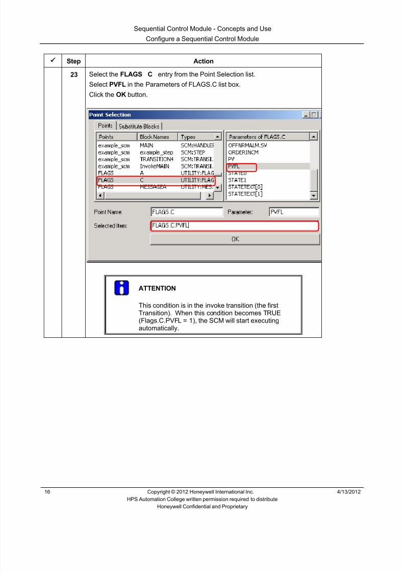
8/9/2019 Student Course Book- Automation
http://slidepdf.com/reader/full/student-course-book-automation 784/1165
Sequential Control Module - Concepts and Use
Configure a Sequential Control Module
16 Copyright © 2012 Honeywell International Inc. 4/13/2012
HPS Automation College written permission required to distributeHoneywell Confidential and Proprietary
Step Action
23 Select the FLAGS C entry from the Point Selection list.
Select PVFL in the Parameters of FLAGS.C list box.
Click the OK button.
ATTENTION
This condition is in the invoke transition (the firstTransition). When this condition becomes TRUE(Flags.C.PVFL = 1), the SCM will start executingautomatically.

8/9/2019 Student Course Book- Automation
http://slidepdf.com/reader/full/student-course-book-automation 785/1165
Sequential Control Module - Concepts and Use
Configure a Sequential Control Module
4/13/2012 Copyright © 2012 Honeywell International Inc. 17
HPS Automation College written permission required to distributeHoneywell Confidential and Proprietary
Step Action
24 The point parameter FLAGS.C.PVFL is now in the expression field, asindicated below.
Click the “ = “ sign and then type “ 1” that is the entered condition is
FLAGS.C.PVFL = 1
ATTENTION
You can use the Expression Builder Buttons to buildexpressions.
You can also enter Expressions through the keyboard.
This first Expression is placed in the first primary gate(GATEP1), by default.

8/9/2019 Student Course Book- Automation
http://slidepdf.com/reader/full/student-course-book-automation 786/1165
Sequential Control Module - Concepts and Use
Configure a Sequential Control Module
18 Copyright © 2012 Honeywell International Inc. 4/13/2012
HPS Automation College written permission required to distributeHoneywell Confidential and Proprietary
Step Action
25 Click the Gates tab to specify a gate for the condition.
Select CONNECT from the Primary Gate (P1) Type drop-down list.
Select CONNECT from the Secondary Gate (S) Type drop-down list.
Click OK.
The Transition Condition displays in the Expression view, as shown
ATTENTION
All transition conditions appear in two views in theSCM:
1. The Description view: Displays descriptionsentered in the Configuration form
2. The Expression view: Displays expressionsentered in the Configuration form

8/9/2019 Student Course Book- Automation
http://slidepdf.com/reader/full/student-course-book-automation 787/1165
Sequential Control Module - Concepts and Use
Configure a Sequential Control Module
4/13/2012 Copyright © 2012 Honeywell International Inc. 19
HPS Automation College written permission required to distributeHoneywell Confidential and Proprietary
Step Action
26 To open the Description view.
Right-click the Transition.
Select SCM Transition Object > Toggle Description/Expression
The Transition condition will display in the Description view, as shown.
• Or, you can click once on the top line
27 Information regarding SCM steps:
A Step contains one or more executable output statements. Up to 16outputs can be part of a single step
If the step block is too close to the surrounding blocks, Control Builderdoes not permit you to enter more outputs in the step. To ensure thatyou can enter all the output statements, add outputs before adding thenext transition
Step outputs appear in two views similar to the Transition Condition:1. The Description View2. The Output View
You can change between the two by clicking the Step heading

8/9/2019 Student Course Book- Automation
http://slidepdf.com/reader/full/student-course-book-automation 788/1165
Sequential Control Module - Concepts and Use
Configure a Sequential Control Module
20 Copyright © 2012 Honeywell International Inc. 4/13/2012
HPS Automation College written permission required to distributeHoneywell Confidential and Proprietary
Step Action
28 Drag a Step block from the SCM library to your SCM chart window.
29 Double-click the Transition End arrow (your pointer turns to a “ + “ sign) andthen move the cursor to the starting line of the Step and click.
This physically connects the transition and the step, as shown below
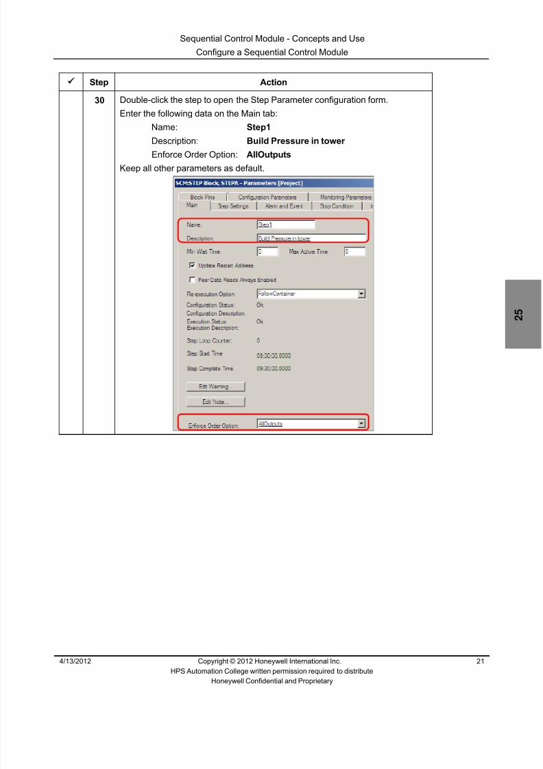
8/9/2019 Student Course Book- Automation
http://slidepdf.com/reader/full/student-course-book-automation 789/1165
Sequential Control Module - Concepts and Use
Configure a Sequential Control Module
4/13/2012 Copyright © 2012 Honeywell International Inc. 21
HPS Automation College written permission required to distributeHoneywell Confidential and Proprietary
Step Action
30 Double-click the step to open the Step Parameter configuration form.
Enter the following data on the Main tab:
Name: Step1
Description: Build Pressure in tower
Enforce Order Option: AllOutputs
Keep all other parameters as default.

8/9/2019 Student Course Book- Automation
http://slidepdf.com/reader/full/student-course-book-automation 790/1165
Sequential Control Module - Concepts and Use
Configure a Sequential Control Module
22 Copyright © 2012 Honeywell International Inc. 4/13/2012
HPS Automation College written permission required to distributeHoneywell Confidential and Proprietary
Step Action
31 Click OK .
32 Click the ADD button to add step output 1.
33 Double-click the blank STEP 1.Enter the following information:
Description HC44 Modeattr = program Output Expression: 11_HC44.AUTOMANA.MODEATTR := 2
ATTENTION
You can use the Points selection list for creatingoutput expressions or enter the expression through thekeyboard.
Click OK .

8/9/2019 Student Course Book- Automation
http://slidepdf.com/reader/full/student-course-book-automation 791/1165
Sequential Control Module - Concepts and Use
Configure a Sequential Control Module
4/13/2012 Copyright © 2012 Honeywell International Inc. 23
HPS Automation College written permission required to distributeHoneywell Confidential and Proprietary
Step Action
34 Click the Add button again to add Output Expression 2.
Double-click the step to open the configuration form and enter the detailsbelow:
Description: HC44 Mode = Man Expression: 11_HC44.AUTOMANA.MODE:= 0
Click OK .

8/9/2019 Student Course Book- Automation
http://slidepdf.com/reader/full/student-course-book-automation 792/1165
Sequential Control Module - Concepts and Use
Configure a Sequential Control Module
24 Copyright © 2012 Honeywell International Inc. 4/13/2012
HPS Automation College written permission required to distributeHoneywell Confidential and Proprietary
Step Action
35 Repeat step 33 to add the following output expressions 3 through 12 accordingto the configuration details displayed below for each new step.
No. Description Expression
3 Open HC44 11_HC44.AUTOMANA.OP := 100.0
4 HC44 Mode Attribute inOperator
11_HC44.AUTOMANA.MODEATTR := 1
5 PC15 Mode attribute inProgram
11_PC15.PIDA.MODEATTR := 2
6 PC15 Mode = manual 11_PC15.PIDA.MODE := 0
7 PC15 valve open 11_PC15.PIDA.OP := 100.0
8 PC15 Mode attribute inOperator
11_PC15.PIDA.MODEATTR := 1
9 PC16 Mode attribute inProgram
11_PC16.PIDA.MODEATTR := 2
10 PC16 Mode = manual 11_PC16.PIDA.MODE:= 0
11 PC16 valve open 11_PC16.PIDA.OP := 100.0
12 PC16 Mode attribute inOperator
11_PC16.PIDA.MODEATTR := 1
36 The Expression/Step Outputs view appears once you finish entering theinformation.

8/9/2019 Student Course Book- Automation
http://slidepdf.com/reader/full/student-course-book-automation 793/1165
Sequential Control Module - Concepts and Use
Configure a Sequential Control Module
4/13/2012 Copyright © 2012 Honeywell International Inc. 25
HPS Automation College written permission required to distributeHoneywell Confidential and Proprietary
Step Action
37 Click the top Step header to view the Description.
Click again to toggle between the Expression and Description views. Thisway, operators can quickly access either view

8/9/2019 Student Course Book- Automation
http://slidepdf.com/reader/full/student-course-book-automation 794/1165
Sequential Control Module - Concepts and Use
Configure a Sequential Control Module
26 Copyright © 2012 Honeywell International Inc. 4/13/2012
HPS Automation College written permission required to distributeHoneywell Confidential and Proprietary
Step Action
38 Add Transition number 2.
Select the SCM group in the Library view and drag a transition to theSCM_Pressure chart view.
Connect Step 1 to TransitionA . Click ADD to add a condition.
Enter the details of the Transition2 block, as shown below.
Double-click the blank Transition 1 and enter the details as described below.Main TabName: Transition2 Description: PC15 >= 49.0 Kpag
Cond#1 TabDescription: Tower Top PC15 GT 49.0 Expression: 11_PC15.PIDA.PV >= 49.0
Gates TabPrimary Gate (P1): CONNECT Secondary Gate (S): CONNECT
Click OK .
39 Add Step2 (by dragging a step block from the Library view.)
Connect TRANSITION2 to STEP2 .
Wire the step to the previous transition.
Configure STEP2 with details given below.
Main TabName: STEP2
Description: Stabilize Pressure in twr

8/9/2019 Student Course Book- Automation
http://slidepdf.com/reader/full/student-course-book-automation 795/1165
Sequential Control Module - Concepts and Use
Configure a Sequential Control Module
4/13/2012 Copyright © 2012 Honeywell International Inc. 27
HPS Automation College written permission required to distributeHoneywell Confidential and Proprietary
Step Action
40 Add outputs as necessary and enter the following step output expressions:
No. Description Expression
1 HC44 Mode attribute inProgram
11_HC44.AUTOMANA.MODEATTR := 2
2 HC44 Mode = Man 11_HC44.AUTOMANA.MODE := 0
3 HC44 set to 20 11_HC44.AUTOMANA.OP := 20.0
4 HC44 Mode attribute inOperator
11_HC44.AUTOMANA.MODEATTR := 1
5 PC15 Mode attribute inProgram
11_PC15.PIDA.MODEATTR := 2
6 PC15 Mode = Auto 11_PC15.PIDA.MODE := 1
7 PC15 SP = 1240 11_PC15.PIDA.SP := 1240.08 PC15 Mode attribute in
Operator11_PC15.PIDA.MODEATTR := 1
9 PC16 Mode attribute inProgram
11_PC16.PIDA.MODEATTR := 2
10 PC16 Mode = Auto 11_PC16.PIDA.MODE:= 1
11 PC 16 SP = 1170 11_PC16.PIDA.SP := 1170.0
12 PC16 Mode attribute inOperator
11_PC16.PIDA.MODEATTR := 1
13 Send SCM CompletedMessage
FLAGS.MESSAGEA.SENDFL[0] :=1
STEP2 after completion is shown below.

8/9/2019 Student Course Book- Automation
http://slidepdf.com/reader/full/student-course-book-automation 796/1165
Sequential Control Module - Concepts and Use
Configure a Sequential Control Module
28 Copyright © 2012 Honeywell International Inc. 4/13/2012
HPS Automation College written permission required to distributeHoneywell Confidential and Proprietary
Step Action
41 Save and close the SCM project chart window.
The SCM appears in the Project window with this symbol
This symbol indicates that this SCM has not yet been downloaded to thecontroller

8/9/2019 Student Course Book- Automation
http://slidepdf.com/reader/full/student-course-book-automation 797/1165
Sequential Control Module - Concepts and Use
Configure a Sequential Control Module
4/13/2012 Copyright © 2012 Honeywell International Inc. 29
HPS Automation College written permission required to distributeHoneywell Confidential and Proprietary
Step Action
42 Right-click the SCM and select Load .

8/9/2019 Student Course Book- Automation
http://slidepdf.com/reader/full/student-course-book-automation 798/1165
Sequential Control Module - Concepts and Use
Configure a Sequential Control Module
30 Copyright © 2012 Honeywell International Inc. 4/13/2012
HPS Automation College written permission required to distributeHoneywell Confidential and Proprietary
Step Action
43 Click Continue and OK .
The SCM is downloaded to the controller as well as to the Serverdatabase
44 Click the Monitoring tab and select SCM_Pressure .

8/9/2019 Student Course Book- Automation
http://slidepdf.com/reader/full/student-course-book-automation 799/1165
Sequential Control Module - Concepts and Use
Configure a Sequential Control Module
4/13/2012 Copyright © 2012 Honeywell International Inc. 31
HPS Automation College written permission required to distributeHoneywell Confidential and Proprietary
Step Action
45 Activate this SCM by right-clicking and selecting Activate > Selected Item(s) .
Click Yes at the “change state” confirmation window.
The color of the SCM changes from blue to green indicating the Activestate. Now if the Invoke Transition condition becomes true, the SCMwill start to execute.
46 Before starting to test your SCM, verify that all points are active and thesimulation spreadsheet is running.
47 Navigate to Station and recall (or refresh) the Debutanizer_123 display.

8/9/2019 Student Course Book- Automation
http://slidepdf.com/reader/full/student-course-book-automation 800/1165
Sequential Control Module - Concepts and Use
Configure a Sequential Control Module
32 Copyright © 2012 Honeywell International Inc. 4/13/2012
HPS Automation College written permission required to distributeHoneywell Confidential and Proprietary
Step Action
48 On the Debutanizer123 graphic, find the following items and change the StartSCM pressure flag to ON (this sets Flag.C.PVFL = 1). This causes the SCM’sinvoke transition to be true and will automatically start SCM_Pressure.
View the SCM in chart view in the Monitoring tab of Control BuilderTransition1 changes to blue when satisfied

8/9/2019 Student Course Book- Automation
http://slidepdf.com/reader/full/student-course-book-automation 801/1165
Sequential Control Module - Concepts and Use
Configure a Sequential Control Module
4/13/2012 Copyright © 2012 Honeywell International Inc. 33
HPS Automation College written permission required to distributeHoneywell Confidential and Proprietary
Step Action
49 On the Debutanizer_123 graphic -- note the status of HC44
11_PC15
The PV of PC15 is controlling toward the SP (1240)
11_PC16
The PV of PC16 is controlling toward the SP (1170)

8/9/2019 Student Course Book- Automation
http://slidepdf.com/reader/full/student-course-book-automation 802/1165
Sequential Control Module - Concepts and Use
Configure a Sequential Control Module
34 Copyright © 2012 Honeywell International Inc. 4/13/2012
HPS Automation College written permission required to distributeHoneywell Confidential and Proprietary
Step Action
50 Click the SP value of 11_PC16 in the Debutanizer_123 to open the faceplate,as shown below.

8/9/2019 Student Course Book- Automation
http://slidepdf.com/reader/full/student-course-book-automation 803/1165
Sequential Control Module - Concepts and Use
Configure a Sequential Control Module
4/13/2012 Copyright © 2012 Honeywell International Inc. 35
HPS Automation College written permission required to distributeHoneywell Confidential and Proprietary
Step Action
51 Similarly click 11_PC15 to open that faceplate.

8/9/2019 Student Course Book- Automation
http://slidepdf.com/reader/full/student-course-book-automation 804/1165
Sequential Control Module - Concepts and Use
Configure a Sequential Control Module
36 Copyright © 2012 Honeywell International Inc. 4/13/2012
HPS Automation College written permission required to distributeHoneywell Confidential and Proprietary
Step Action
Open the Monitoring view of the SCM chart. The toolbar has a combo boxgiving zooming facility, select 50%
The SCM is complete and all steps and transitions are blue
The SCM “COMPLETE” status is shown on the title bar, as illustrated
below

8/9/2019 Student Course Book- Automation
http://slidepdf.com/reader/full/student-course-book-automation 805/1165
Sequential Control Module - Concepts and Use
Configure a Sequential Control Module
4/13/2012 Copyright © 2012 Honeywell International Inc. 37
HPS Automation College written permission required to distributeHoneywell Confidential and Proprietary
Step Action
52 The Message tab in the Status line of Station starts flashing green.
Click the Message Field to open the Message Summary window.
Acknowledge the message.
53 Turn off the Start SCM pressure flag. This will turn off the flag that triggersSCM_Pressure.
54 In the Monitoring tab, open the SCM.
Double-click in a blank area.
Click the Status tab.
Change the Command to Reset (which takes the SCM State to Idle).

8/9/2019 Student Course Book- Automation
http://slidepdf.com/reader/full/student-course-book-automation 806/1165
Sequential Control Module - Concepts and Use
Configure a Sequential Control Module
38 Copyright © 2012 Honeywell International Inc. 4/13/2012
HPS Automation College written permission required to distributeHoneywell Confidential and Proprietary
This page was intentionally left blank.

8/9/2019 Student Course Book- Automation
http://slidepdf.com/reader/full/student-course-book-automation 807/1165
1
1
Honeywell ConfidentialCopyright © 2012 Honeywell International Inc.
4/13/2012
Identify SCM Programming Techniques
SCMs - Programming Techniques, Operation Identify SCM Programming TechniquesSCMs - Programming Techniques, Operation Identify SCM Programming Techniques
Honeywell
Honeywell ConfidentialCopyright © 2012 Honeywell International Inc.
4/13/20122
Introduction
• In this lesson you will learn to add functionality to Sequential ControlModules (SCMs)
• At the conclusion of this lesson, you will be able to describe the purposeand operation of:
– Branching and looping functionality
– Parallel execution functionality
– Exception handlers
SCMs - Programming Techniques, Operation Identify SCM Programming Techniques

8/9/2019 Student Course Book- Automation
http://slidepdf.com/reader/full/student-course-book-automation 808/1165
2
Honeywell
Honeywell ConfidentialCopyright © 2012 Honeywell International Inc.
4/13/20123
Topics
• SCM Branching and Looping
• SCM Parallel Execution
• SCM Exception Handlers
• SCM Retry Option
SCMs - Programming Techniques, Operation Identify SCM Programming Techniques
Honeywell
Honeywell ConfidentialCopyright © 2012 Honeywell International Inc.
4/13/20124
Sequential Control Modules – Branching
Example of SCM Branching
TRANSITION A TRANSITION CTRANSITION B
(1) (3)(2)
STEP
TRANSITION
STEP
STEP
NEXTCOMPPINS
Alternate paths.Only one executes.If multiple transitionsare true, the leftmostexecutes
Up to 10 branches canbe added to a step.
SCMs - Programming Techniques, Operation Identify SCM Programming Techniques

8/9/2019 Student Course Book- Automation
http://slidepdf.com/reader/full/student-course-book-automation 809/1165
3
Honeywell
Honeywell ConfidentialCopyright © 2012 Honeywell International Inc.
4/13/20125
Sequential Control Modules - Looping
• Recommended – End with a Transition then loop back
into a Step/Phase
• Not recommended – Loop from Step/Phase back to always
true transition – Loop back to the default invoke transition – Loop from a parallel section to non
parallel section – Loop from a non-parallel section to a
parallel section
Example of SCM Looping
TRANSITIONTRANSITION
STEP
TRANSITION
STEP
STEP
A Phase block is availablein an RCM, but not in an SCM.RCMs are beyond the scopeof this class.
SCMs - Programming Techniques, Operation Identify SCM Programming Techniques
Honeywell
Honeywell ConfidentialCopyright © 2012 Honeywell International Inc.
4/13/20126
Question 1: SCM Branching
Incorrect. Branching occurs at a step.
Click anywhere to continue.
Correct! Branching occurs at a step.
Click anywhere to continue.
Incorrect. Branching occurs at a step.
Click anywhere to continue.
Incorrect. Branching occurs at a step.
Click anywhere to continue.Correct - Click anywhere to continueIncorrect - Click anywhere to continueYou answered this correctly!
Your answer: The correct answer is:
You did not answer this question completelyYou must answer the question beforecontinuing
Submit Clear
At which SCM function blockdoes branching occur?
A) Handler
B) Step
C) Synchronization
D) Transition
SCMs - Programming Techniques, Operation Identify SCM Programming Techniques

8/9/2019 Student Course Book- Automation
http://slidepdf.com/reader/full/student-course-book-automation 810/1165
4
Honeywell
Honeywell ConfidentialCopyright © 2012 Honeywell International Inc.
4/13/20127
• SCM Branching and Looping
• SCM Parallel Execution
• SCM Exception Handlers
• SCM Retry Option
Topics
SCMs - Programming Techniques, Operation Identify SCM Programming Techniques
Honeywell
Honeywell ConfidentialCopyright © 2012 Honeywell International Inc.
4/13/20128
Parallel Step Execution
TRANSITION
SYNC
STEP STEP
SYNC
TRANSITION
STEP
TRANSITION
STEP
TRANSITION
STEP
TRANSITION
STEP
NEXTCOMPPINS
Parallel paths.All paths execute.
SCMs - Programming Techniques, Operation Identify SCM Programming Techniques

8/9/2019 Student Course Book- Automation
http://slidepdf.com/reader/full/student-course-book-automation 811/1165
5
Honeywell
Honeywell ConfidentialCopyright © 2012 Honeywell International Inc.
4/13/20129
SYNC
SYNC
TRANSITION
STEP STEP
TRANSITION
STEPSTEP
TRANSITION
Synchronization Block
• A synchronization (sync) blockbegins and ends a parallel stepexecution.
• The end synchronization block:
– Monitors the execution status ofeach parallel path
– Terminates the thread when theexecution of the path completes
– Starts one or several new threadswhen all the preceding parallelpaths complete execution
SCMs - Programming Techniques, Operation Identify SCM Programming Techniques
Honeywell
Honeywell ConfidentialCopyright © 2012 Honeywell International Inc.
4/13/201210
TRANSITION
STEP STEP
SYNC
TRANSITION
STEPSTEP
TRANSITION
SYNC
Synchronization Block
• A synchronization block can havea maximum of 10 threads.
• Nested synchronization blocks arepermitted.
– Nested levels are limited to 9 dueto the limit of 10 threads persynchronization block.
• When Sync is followed byTransitions, ALL must be truebefore execution of any pathbegins execution
• When Sync is followed by Steps,each path executes independently(until the “end Sync”)
SCMs - Programming Techniques, Operation Identify SCM Programming Techniques

8/9/2019 Student Course Book- Automation
http://slidepdf.com/reader/full/student-course-book-automation 812/1165
6
Honeywell
Honeywell ConfidentialCopyright © 2012 Honeywell International Inc.
4/13/201211
Question 2: Parallel Step Execution
Incorrect. Parallel step execution begins with aSynchronization block.
Click anywhere to continue.
Incorrect. Parallel step execution begins with aSynchronization block.
Click anywhere to continue.
Correct! Parallel step execution begins with aSynchronization block.
Click anywhere to continue.
Incorrect. Parallel step execution begins with aSynchronization block.
Click anywhere to continue.
Correct - Click anywhere to continueIncorrect - Click anywhere to continueYou answered this correctly!
Your answer: The correct answer is:
You did not answer this question completelyYou must answer the question beforecontinuing
Submit Clear
Parallel step execution begins with which of the following blocks?
TRANSITION
STEP
HANDLER
SYNC
A) Handler
B) Step
C) Synchronization
D) Transition
SCMs - Programming Techniques, Operation Identify SCM Programming Techniques
Honeywell
Honeywell ConfidentialCopyright © 2012 Honeywell International Inc.
4/13/201212
• SCM Branching and Looping
• SCM Parallel Execution
• SCM Exception Handlers
• SCM Retry Option
Topics
SCMs - Programming Techniques, Operation Identify SCM Programming Techniques

8/9/2019 Student Course Book- Automation
http://slidepdf.com/reader/full/student-course-book-automation 813/1165
7
Honeywell
Honeywell ConfidentialCopyright © 2012 Honeywell International Inc.
4/13/201213
Sequential Control Modules - Exception Handlers
• Exception handlers are transitions and steps that run only after specifiedconditions have been met
• An SCM can have multiple handlers but only one handler of each typemay be active at any given time
• Handler types, in priority order, are:
– Abort
– Stop
– Hold
– Restart
– Interrupt
– Check
– Main
Handler priority
SCMs - Programming Techniques, Operation Identify SCM Programming Techniques
Honeywell
Honeywell ConfidentialCopyright © 2012 Honeywell International Inc.
4/13/201214
Sequential Control Modules - Exception Handlers
• Handlers can be classified into three categories:
– Internal (Null, Edit)
– Normal (Main, Check, Interrupt)
– Abnormal (Restart, Stop, Hold, Abort)
CHECK
STOPHOLD
INTERRUPT
ABORT
MAIN
RESTART
This drawing doesnot show allpossible paths
SCMs - Programming Techniques, Operation Identify SCM Programming Techniques

8/9/2019 Student Course Book- Automation
http://slidepdf.com/reader/full/student-course-book-automation 814/1165
8
Honeywell
Honeywell ConfidentialCopyright © 2012 Honeywell International Inc.
4/13/201215
Interrupt Handler
• Interrupts the activity of the main handler, acting like a subroutine of themain handler
• When it completes, the program activity returns to the last step in themain handler that had the Update Restart Address option ON
CHECK
STOPHOLD
ABORT
MAIN
RESTART
Interrupt
Used for normal process handling
Example: Making tomato soup –tomatoes have an unknown cook timedue to variations in water content
Interrupt trigger condition - viscosity < 55Handler - heat till viscosity > 60
This drawing doesnot show allpossible paths
SCMs - Programming Techniques, Operation Identify SCM Programming Techniques
Honeywell
Honeywell ConfidentialCopyright © 2012 Honeywell International Inc.
4/13/201216
Hold and Restart Handlers
• The hold handler preempts the activity of the main and/or interrupthandlers.
– The stop and abort handlers can preempt the hold handler.
– From the hold handler you can go to the restart, stop, or abort handler.
• The restart handler can only be initiated from the held state.
– It returns the activity to the main/interrupt handler at the last step with theUpdate Restart Address checked.
CHECK
STOP
MAIN
Hold
Restart INTERRUPT
Used for an abnormal process condition
Example: Loss of steamHold trigger condition - wax temperature < 120
Handler – pump tank contents to preheat tankRestart – preheat tank temperature > 125
This drawing doesnot show allpossible paths
SCMs - Programming Techniques, Operation Identify SCM Programming Techniques

8/9/2019 Student Course Book- Automation
http://slidepdf.com/reader/full/student-course-book-automation 815/1165
9
Honeywell
Honeywell ConfidentialCopyright © 2012 Honeywell International Inc.
4/13/201217
Restart Address
Program execution will begin at the last checked UpdateRestart Address (step) when returning from a interrupt or
hold/restart handler call.
SCMs - Programming Techniques, Operation Identify SCM Programming Techniques
Honeywell
Honeywell ConfidentialCopyright © 2012 Honeywell International Inc.
4/13/201218
Abort Handler
• Preempts the activity of the main, interrupt, restart, hold, or stop handlers• Cannot be preempted• From the abort handler, you can only return to the check handler.
Used for an abnormal process condition
Example: milk overheated Abort trigger condition – milk temperature > 198
Handler – dump tanks to waste
CHECK
STOP
MAIN
RESTART Abort
HOLD
INTERRUPT
This drawing doesnot show all
possible paths
SCMs - Programming Techniques, Operation Identify SCM Programming Techniques

8/9/2019 Student Course Book- Automation
http://slidepdf.com/reader/full/student-course-book-automation 816/1165
10
Honeywell
Honeywell ConfidentialCopyright © 2012 Honeywell International Inc.
4/13/201219
Stop Handler
• Preempts the activity of the main/interrupt, restart, or hold handler
• Abort handler can preempt the stop handler.
• From the stop handler, you can go automatically to the abort or checkhandler or by command to the hold handler.
CHECK
INTERRUPT
ABORT
MAIN
RESTART
StopHOLD
This drawing doesnot show allpossible paths
SCMs - Programming Techniques, Operation Identify SCM Programming Techniques
Honeywell
Honeywell ConfidentialCopyright © 2012 Honeywell International Inc.
4/13/201220
Check Handler
• The SCM executes the check handler just before entering the IDLEstate.
STOPHOLD
INTERRUPT
ABORTRESTART
Check
MAIN
• On initial entry to the SCM, the check handler is executed as soon asthe SCM is activated.
• The SCM also returns to the check handler after a RESET command orwhen the conditions for the check handler are met after the stop handler,main handler, or abort handler is completed.
• A configured check handler can be used to initialize process equipmentand/or reset values for a new activity.
Example:Reset totalizers, historize values, etc.
This drawing doesnot show allpossible paths
SCMs - Programming Techniques, Operation Identify SCM Programming Techniques
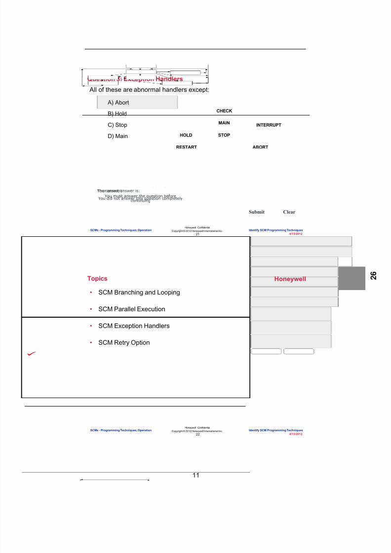
8/9/2019 Student Course Book- Automation
http://slidepdf.com/reader/full/student-course-book-automation 817/1165
11
Honeywell
Honeywell ConfidentialCopyright © 2012 Honeywell International Inc.
4/13/201221
Question 3: Exception Handlers
Incorrect. All are abnormal handlers
except "Main".
Click anywhere to continue.
Incorrect. All are abnormal handlers
except "Main".
Click anywhere to continue.
Incorrect. All are abnormal handlers
except "Main".
Click anywhere to continue.
Correct! All are abnormal handlers
except "Main".
Click anywhere to continue.Correct - Click anywhere to continueIncorrect - Click anywhere to continueYou answered this correctly!
Your answer: The correct answer is:
You did not answer this question completelyYou must answer the question beforecontinuing
Submit Clear
All of these are abnormal handlers except:
CHECK
STOPHOLD
INTERRUPT
ABORT
MAIN
RESTART
A) Abort
B) Hold
C) Stop
D) Main
SCMs - Programming Techniques, Operation Identify SCM Programming Techniques
Honeywell
Honeywell ConfidentialCopyright © 2012 Honeywell International Inc.
4/13/201222
• SCM Branching and Looping
• SCM Parallel Execution
• SCM Exception Handlers
• SCM Retry Option
Topics
SCMs - Programming Techniques, Operation Identify SCM Programming Techniques

8/9/2019 Student Course Book- Automation
http://slidepdf.com/reader/full/student-course-book-automation 818/1165
12
Honeywell
Honeywell ConfidentialCopyright © 2012 Honeywell International Inc.
4/13/201223
Retry Option
• Starting in R400, a newconfiguration option has beenadded: Retry Option – Specifies the number of retries
a step block will perform for afailed step output
– Available on the main tab ofthe SCM/RCM
– Cannot be changed inmonitoring
RetryN – N defines number ofretries for a failed outputDefault – Performs endless retries
SCMs - Programming Techniques, Operation Identify SCM Programming Techniques
Honeywell
Honeywell ConfidentialCopyright © 2012 Honeywell International Inc.
4/13/201224
Affect Of RETRYOPT In Various Operational Scenarios
Operational Scenario /RETRYOPT
Default Retry0 RetryN ( N > 0 )
Impact of output errors onnormal execution(MODE=AUTO)
Step nevercompletes as long asat least one outputhas an error
Step completesimmediately after alloutputs are processedone time, regardless oftheir success.
Step completes after N failed retries or aftersuccess , whichever comes first.
Automatic recovery ofoutput and step if Retrieshave not Expired
Step will alwaysrecover automaticallyif the conditioncausing the outputstore error has beencorrected (e.g.destination hadwrong MODEATTRand MODEATTRwas changed toPROGRAM )
Not applicable Step wil l recover automatical ly if the conditioncausing the output store error has beencorrected (e.g. destination had wrongMODEATTR and MODEATTR was changedto PROGRAM ) , while retries have notexpired.
Automatic recovery ofoutput and step if Retrieshave expired
Step will not automatically recover from errors
How can an operatorwork around failedoutputs(MODE=AUTO)
Operator can bypassthe output. This willcause the step tocomplete ( if no othererrors are present ).
Not required. Bypassingwill have no effect.
Bypassing the outputs is possible as long asthe Retries of the outputs are not expired.
SCMs - Programming Techniques, Operation Identify SCM Programming Techniques

8/9/2019 Student Course Book- Automation
http://slidepdf.com/reader/full/student-course-book-automation 819/1165
13
Honeywell
Honeywell ConfidentialCopyright © 2012 Honeywell International Inc.
4/13/201225
• Functionality you may add to an SCM includes:
– Branching, which occurs at a step and allows the SCM to take differentpaths based on the first true transition found
– Parallel step execution, which begins and ends with a synchronization (sync)block
• The end synchronization block starts one or several new threads
• When all the preceding parallel paths complete execution.
– Exception handlers, which are transitions and steps that run only afterspecified conditions have been met
– SCM supports a Retry Option, wherein a SCM will retry for specified numberof times before declaring a particular Step output / Step as failed
Summary
SCMs - Programming Techniques, Operation Identify SCM Programming Techniques
Honeywell
Honeywell ConfidentialCopyright © 2012 Honeywell International Inc.
4/13/201226
Conclusion
Identify SCM Programming Techniques
CompletionCertificate
Proceed to the next lesson in your course material.
SCMs - Programming Techniques, Operation Identify SCM Programming Techniques

8/9/2019 Student Course Book- Automation
http://slidepdf.com/reader/full/student-course-book-automation 820/1165
14
27
Honeywell ConfidentialCopyright © 2012 Honeywell International Inc.
4/13/2012
Explain the Operation of SCMs
SCMs - Programming Techniques, Operation Explain the Operation of SCMsSCMs - Programming Techniques, Operation Explain the Operation of SCMs
Honeywell
Honeywell ConfidentialCopyright © 2012 Honeywell International Inc.
4/13/201228
Introduction
• In this lesson you will learn about theoperation of SCMs.
• At the conclusion of this lesson, youwill be able to:
– Describe the recipe and history datathat can be stored for an SCM
– Explain the process an SCM followswhen it is activated
– Describe the operation of an SCM as itappears in the station chart tab
– Identify the SCM execution modes
– Identify the SCM event options
SCMs - Programming Techniques, Operation Explain the Operation of SCMs

8/9/2019 Student Course Book- Automation
http://slidepdf.com/reader/full/student-course-book-automation 821/1165
15
Honeywell
Honeywell ConfidentialCopyright © 2012 Honeywell International Inc.
4/13/201229
Topics
• SCM Recipes and History
• SCM Activation and Operation
• SCM Modes and Event Options
• SCM Force and Bypass operations
SCMs - Programming Techniques, Operation Explain the Operation of SCMs
Honeywell
Honeywell ConfidentialCopyright © 2012 Honeywell International Inc.
4/13/201230
Sequential Control Modules - Recipes
• A maximum of 50 recipe values can be stored for an SCM
• Recipe data can include:
– Descriptors
– SP, PV access locks
– Scaling options
– High and low limits
– Default values
– Display and print options
SCMs - Programming Techniques, Operation Explain the Operation of SCMs

8/9/2019 Student Course Book- Automation
http://slidepdf.com/reader/full/student-course-book-automation 822/1165
16
Honeywell
Honeywell ConfidentialCopyright © 2012 Honeywell International Inc.
4/13/201231
Sequential Control Modules - History
• A maximum of 50 history parameter values can be stored for an SCM.
• Process data can be collected and stored during SCM operation.
• History data will include:
– Parameter descriptor
– Parameter types
– Parameter value
SCMs - Programming Techniques, Operation Explain the Operation of SCMs
Honeywell
Honeywell ConfidentialCopyright © 2012 Honeywell International Inc.
4/13/201232
Question 1: SCM Recipes and History
Yes! Process data can be collected andstored during SCM operation using amaximum of 50 history parameters.
Click anywhere to continue.
No. Process data can be collected andstored during SCM operation using amaximum of 50 history parameters.
Click anywhere to continue.
No. Process data can be collected andstored during SCM operation using amaximum of 50 history parameters.
Click anywhere to continue.
No. Process data can be collected andstored during SCM operation using amaximum of 50 history parameters.
Click anywhere to continue.
Correct - Click anywhere to continueIncorrect - Click anywhere to continueYou answered this correctly!
Your answer:The correct answer is:
You did not answer this question completelyYou must answer the question beforecontinuing
Submit Clear
Process data can be collected andstored during SCM operation:
A) Using a maximum of 50history parameters
B) Using a maximum of 500parameters
C) To send information to theSCM prior to execution
D) To upload recipe valueswhen an SCM runs tocompletion
SCMs - Programming Techniques, Operation Explain the Operation of SCMs

8/9/2019 Student Course Book- Automation
http://slidepdf.com/reader/full/student-course-book-automation 823/1165
17
Honeywell
Honeywell ConfidentialCopyright © 2012 Honeywell International Inc.
4/13/201233
Topics
• SCM Recipes and History
• SCM Activation and Operation
• SCM Modes and Event Options
• SCM Force and Bypass operations
SCMs - Programming Techniques, Operation Explain the Operation of SCMs
Honeywell
Honeywell ConfidentialCopyright © 2012 Honeywell International Inc.
4/13/201234
IDLE
RUNNING
INACTIVE(1st State After Download)
VALIDATED
START
ABORTED ABORT
RESET
HELD
ABORT
COMPLETE
INTERRUPTING
INTERRUPT
RESET
INACTIVE ACTIVE
STOPPED
STOP
HOLDSTOP
HOLD RESTART
RESET
RESUME
ABORT RESET
Sequential Control Modules - SCM Activation
SCMs - Programming Techniques, OperationExplain the Operation of SCMs
EXP2001R400 - EPKS CEE R400SCMs - Programming Techniques, Operation Explain the Operation of SCMs
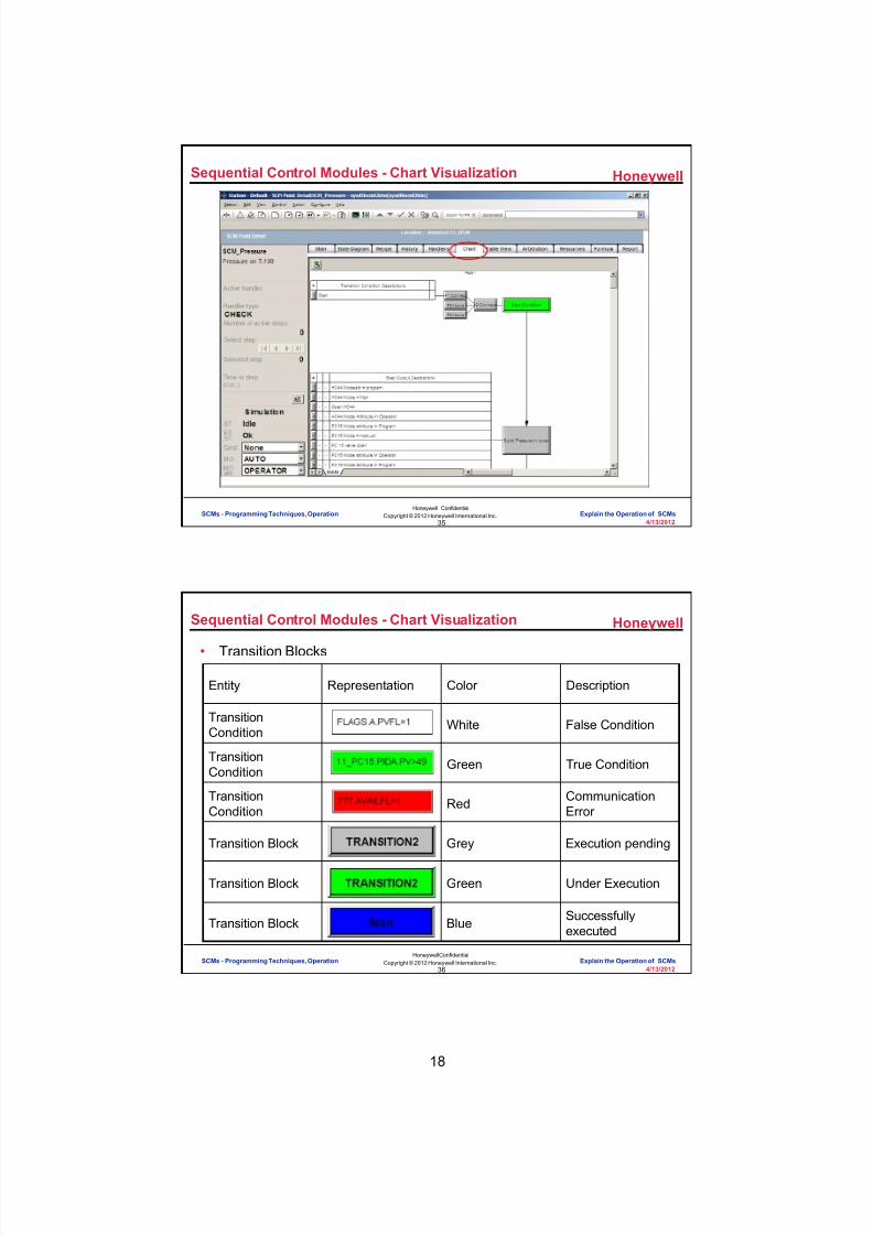
8/9/2019 Student Course Book- Automation
http://slidepdf.com/reader/full/student-course-book-automation 824/1165
18
Honeywell
Honeywell ConfidentialCopyright © 2012 Honeywell International Inc.
4/13/201235
Sequential Control Modules - Chart Visualization
SCMs - Programming Techniques, Operation Explain the Operation of SCMs
Honeywell
Honeywell ConfidentialCopyright © 2012 Honeywell International Inc.
4/13/201236
Sequential Control Modules - Chart Visualization
• Transition Blocks
Entity Representation Color Description
TransitionCondition White False Condition
TransitionCondition Green True Condition
TransitionCondition Red Communication
Error
Transition Block Grey Execution pending
Transition Block Green Under Execution
Transition Block Blue Successfullyexecuted
SCMs - Programming Techniques, Operation Explain the Operation of SCMs

8/9/2019 Student Course Book- Automation
http://slidepdf.com/reader/full/student-course-book-automation 825/1165
19
Honeywell
Honeywell ConfidentialCopyright © 2012 Honeywell International Inc.
4/13/201237
Sequential Control Modules - Chart Visualization
• Step Blocks
Entity Representation Color Description
Step Output Green Under Execution
Step OutputBlue Successfully
Executed
Step OutputRed Communication
Error
Step OutputYellow Out of Range
Operation
Step BlockGreen Under Execution
Step BlockDark Green Successfully
Executed
SCMs - Programming Techniques, Operation Explain the Operation of SCMs
Honeywell
Honeywell ConfidentialCopyright © 2012 Honeywell International Inc.
4/13/201238
Question 2: SCM Activation and Operation
Incorrect. The false statement is " Whenoperating an SCM, you must always invoke
an exception handler from running".
Click anywhere to continue.
Incorrect. The false statement is " Whenoperating an SCM, you must always invoke
an exception handler from running".
Click anywhere to continue.
Correct! The false statement is " Whenoperating an SCM, you must always invoke
an exception handler from running".
Click anywhere to continue.
Correct - Click anywhere to continueIncorrect - Click anywhere to continueYou answered this correctly!
Your answer:The correct answer is:
You did not answer this question completelyYou must answer the question beforecontinuing
Submit Clear
Which statement is false ? Whenoperating an SCM, you must always:
A) Reset to return to Idle
B) Return to Idle before Inactive
C) Invoke an exception handlerfrom Running
SCMs - Programming Techniques, Operation Explain the Operation of SCMs

8/9/2019 Student Course Book- Automation
http://slidepdf.com/reader/full/student-course-book-automation 826/1165
20
Honeywell
Honeywell ConfidentialCopyright © 2012 Honeywell International Inc.
4/13/201239
Topics
• SCM Recipes and History
• SCM Activation and Operation
• SCM Modes and Event Options
• SCM Force and Bypass operations
SCMs - Programming Techniques, Operation Explain the Operation of SCMs
Honeywell
Honeywell ConfidentialCopyright © 2012 Honeywell International Inc.
4/13/201240
Sequential Control Modules - Modes
• Execution Modes – Automatic
• Run to “Complete”, with normal interventions – Semi-automatic
• Pause after each step, wait for Resume commandand execute the next step
• Obeys Transitions – Single step
• Pause after each step, wait for Resume commandand execute the selected Target Step(s)
• Ignores Transitions – Safe step
• Like Single step, but allows “jumping” only to pre-defined areas• Manual Mode stops SCM execution• Normal Mode used with operator or GUS keyboard NORM
key to go to an SCM’s configured execution mode
SCMs - Programming Techniques, Operation Explain the Operation of SCMs

8/9/2019 Student Course Book- Automation
http://slidepdf.com/reader/full/student-course-book-automation 827/1165
21
Honeywell
Honeywell ConfidentialCopyright © 2012 Honeywell International Inc.
4/13/201241
Sequential Control Modules - Event Options
• SCM Alarm and Event tab:
• Step Alarm and Event tab:
SCMs - Programming Techniques, Operation Explain the Operation of SCMs
Honeywell
Honeywell ConfidentialCopyright © 2012 Honeywell International Inc.
4/13/201242
Question 3: SCM Modes
Incorrect. The 'Semi-Automatic' mode pauses the
SCM after the completion of each step and waitsfor the resume command, upon resuming,
completes the next step.
Click anywhere to continue.
Incorrect. The 'Semi-automatic' mode pauses the
SCM after the completion of each step and waitsfor the resume command, upon resuming,
completes the next step.
Click anywhere to continue.
Incorrect. The 'Semi-Automatic' mode pauses theSCM after the completion of each step and waits
for the resume
Click anywhere to continue.
Correct
Click anywhere to continue.Correct - Click anywhere to continueIncorrect - Click anywhere to continueYou answered this correctly!
Your answer:The correct answer is:You did not answer this question completelyYou must answer the question before
continuing
Submit Clear
Which mode pauses the SCM after each step,waits for the resume command and, upon resuming,completes the next step?
A) Automatic
B) Normal
C) Single Step
D) Semi-Automatic
SCMs - Programming Techniques, Operation Explain the Operation of SCMs

8/9/2019 Student Course Book- Automation
http://slidepdf.com/reader/full/student-course-book-automation 828/1165
22
Honeywell
Honeywell ConfidentialCopyright © 2012 Honeywell International Inc.
4/13/201243
Topics
• SCM Recipes and History
• SCM Activation and Operation
• SCM Modes and Event Options
• SCM Force and Bypass operations
SCMs - Programming Techniques, Operation Explain the Operation of SCMs
Honeywell
Honeywell ConfidentialCopyright © 2012 Honeywell International Inc.
4/13/201244
SCM Transition Condition Force Requests
• A condition in the SCM transition block can be forced to On or Off, if theForce Permit flag is ON
• SCM Transition condition Force Permit is used – To override a false condition, or – To stop SCM execution when the invoke transition is always true and the
SCM is designed in a continually executing loop
SCMs - Programming Techniques, Operation Explain the Operation of SCMs

8/9/2019 Student Course Book- Automation
http://slidepdf.com/reader/full/student-course-book-automation 829/1165
23
Honeywell
Honeywell ConfidentialCopyright © 2012 Honeywell International Inc.
4/13/201245
SCM Transition Force
To force a condition, first Enable theForce Permit checkbox
* Allowed online
Then select an option fromthe drop down list:
ToOff : Force to turn OFFToOn : Force to turn ONNone : No Force
SCMs - Programming Techniques, Operation Explain the Operation of SCMs
Honeywell
Honeywell ConfidentialCopyright © 2012 Honeywell International Inc.
4/13/201246
Transition Force Request Status
• Transition condition Force Request state is reflected on that specificCondition’s properties form – Execution Status of that condition can be viewed while the SCM is executing
ForceRequest set
Execution Statusshows “Bypass”
Indicates Force State“1” If Forced to turn ON“0” If Forced to turn OFF“-” If not Forced
SCMs - Programming Techniques, Operation Explain the Operation of SCMs

8/9/2019 Student Course Book- Automation
http://slidepdf.com/reader/full/student-course-book-automation 830/1165
24
Honeywell
Honeywell ConfidentialCopyright © 2012 Honeywell International Inc.
4/13/201247
SCM Execution Status Bypass
• SCM Execution Status indicates ypass if any condition of any transitionis forced (ToOn, or ToOff)
Invoke
Step
Trans
Step
Trans
Forced
SCMs - Programming Techniques, Operation Explain the Operation of SCMs
Honeywell
Honeywell ConfidentialCopyright © 2012 Honeywell International Inc.
4/13/201248
Bypass Cancel Option
• Bypass Cancel Option on SCM Main tab can cancel or clear TransitionForce permit/Force Request conditions – Applies to all transitions of all handlers contained in SCM – Can be changed while the SCM is executing
Select the appropriate Bypass CancelOption:None - Bypassed/forced TransitionConditions are not canceled/clearedOnSCMReset - Bypassed/forced TransitionConditions are canceled/cleared on SCMReset commandOnTransEnd - Bypassed/forced TransitionConditions are canceled/cleared when theTransition evaluation finishes (Transitionchanged from Enabled to Disabled state)
* Allowed onlineSCMs - Programming Techniques, Operation Explain the Operation of SCMs

8/9/2019 Student Course Book- Automation
http://slidepdf.com/reader/full/student-course-book-automation 831/1165
25
Honeywell
Honeywell ConfidentialCopyright © 2012 Honeywell International Inc.
4/13/201249
SCM Step Output Force Request
• Unlike SCM Transition conditions, the SCM STEP Output expressionscannot be Forced to On or Off – SCM Step Output can be Skipped
Select Skip tobypass the
execution of STEPcondition
SCMs - Programming Techniques, Operation Explain the Operation of SCMs
Honeywell
Honeywell ConfidentialCopyright © 2012 Honeywell International Inc.
4/13/201250
SCM Step Force Request – Skip
Invoke
Step
Trans
Step
Trans
SkipOutput # 1Output # 2Output # 3
• If the Step Output processing cannot complete, then using the ForceRequest: – Will let the Step proceed, as if the Output completed immediately and
successfully – This is most useful for allowing Steps with failed Outputs to proceed
SCMs - Programming Techniques, Operation Explain the Operation of SCMs
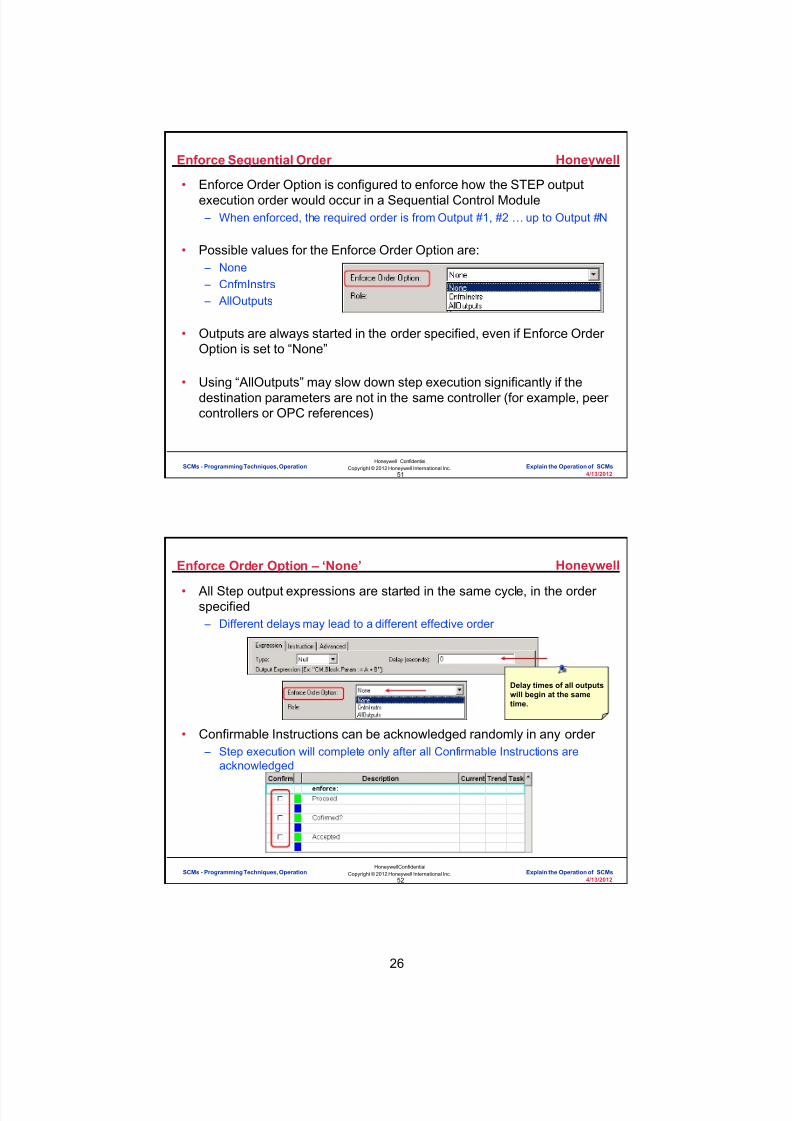
8/9/2019 Student Course Book- Automation
http://slidepdf.com/reader/full/student-course-book-automation 832/1165
26
Honeywell
Honeywell ConfidentialCopyright © 2012 Honeywell International Inc.
4/13/201251
Enforce Sequential Order
• Enforce Order Option is configured to enforce how the STEP outputexecution order would occur in a Sequential Control Module – When enforced, the required order is from Output #1, #2 … up to Output #N
• Possible values for the Enforce Order Option are: – None – CnfmInstrs – AllOutputs
• Outputs are always started in the order specified, even if Enforce OrderOption is set to “None”
• Using “AllOutputs” may slow down step execution significantly if thedestination parameters are not in the same controller (for example, peercontrollers or OPC references)
SCMs - Programming Techniques, Operation Explain the Operation of SCMs
Honeywell
Honeywell ConfidentialCopyright © 2012 Honeywell International Inc.
4/13/201252
Enforce Order Option – ‘None’
• All Step output expressions are started in the same cycle, in the orderspecified – Different delays may lead to a different effective order
• Confirmable Instructions can be acknowledged randomly in any order – Step execution will complete only after all Confirmable Instructions are
acknowledged
Delay times of all outputswill begin at the sametime.
SCMs - Programming Techniques, Operation Explain the Operation of SCMs

8/9/2019 Student Course Book- Automation
http://slidepdf.com/reader/full/student-course-book-automation 833/1165
27
Honeywell
Honeywell ConfidentialCopyright © 2012 Honeywell International Inc.
4/13/201253
Enforce Order Option – ‘CnfmInstrs’
• If CnfmInstrs is selected, the order of Confirmable Instructions isenforced – All outputs are started at the same time
• All Output expressions are processed and executed – Output expressions with Confirmable Instructions must be acknowledged in
a sequential order Delay times of all non-confirmable outputswill begin at the sametime.
SCMs - Programming Techniques, Operation Explain the Operation of SCMs
Honeywell
Honeywell ConfidentialCopyright © 2012 Honeywell International Inc.
4/13/201254
Enforce Order Option – ‘AllOutputs’
• Order of all Outputs is enforced; an output is executed only after theprevious output has completed execution including all delays andinstruction confirmations – Step active time cannot be smaller than the total sum of all output delays
Delay time of each stepoutput does not beginuntil the previous outputcompletes.
SCMs - Programming Techniques, Operation Explain the Operation of SCMs

8/9/2019 Student Course Book- Automation
http://slidepdf.com/reader/full/student-course-book-automation 834/1165
28
Honeywell
Honeywell ConfidentialCopyright © 2012 Honeywell International Inc.
4/13/201255
Enable Step-level Confirmation of Instructions
• Specifies whether a Step-level confirmation of all ConfirmableInstructions is enabled for the Step – Step-level confirmation is possible only when this option is selected and
when the Enforce Sequential Order option is not equal to AllOutputs
With None selected With ‘CnfmInstrs’ selected
In this case, the checkboxwill have to be checkedthree times once for eachconfirmable instruction.
In this case, thecheckbox will onlyhave to bechecked once.
SCMs - Programming Techniques, Operation Explain the Operation of SCMs
Honeywell
Honeywell ConfidentialCopyright © 2012 Honeywell International Inc.
4/13/201256
Summary
• An SCM: – Can contain up to 50:
• Sets of recipe parameters, such as descriptors and SP and PV accesslocks, which are accessible from the SCM detail display once the SCM isactive.
• History parameters including parameter descriptors, types and valuesthat are collected and stored during SCM operation.
– Status is indicated using state descriptors such as inactive, idle, running andstopped for which specific paths must be followed.
– Can be viewed and operated from the station chart tab which shows thestatus of transitions and steps using colors such as blue which indicates atransition is complete.
– Has modes of operation that include automatic, semi-automatic, single step,manual and normal.
SCMs - Programming Techniques, Operation Explain the Operation of SCMs

8/9/2019 Student Course Book- Automation
http://slidepdf.com/reader/full/student-course-book-automation 835/1165
29
Honeywell
Honeywell ConfidentialCopyright © 2012 Honeywell International Inc.
4/13/201257
Lab Examples – 1 of 7
• Configure a Sequential Control Module (SCM)
SCMs - Programming Techniques, Operation Explain the Operation of SCMs
Honeywell
Honeywell ConfidentialCopyright © 2012 Honeywell International Inc.
4/13/201258
Lab Examples – 2 of 7
• Add Function Blocks for SCM Program Control
SCMs - Programming Techniques, Operation Explain the Operation of SCMs

8/9/2019 Student Course Book- Automation
http://slidepdf.com/reader/full/student-course-book-automation 836/1165
30
Honeywell
Honeywell ConfidentialCopyright © 2012 Honeywell International Inc.
4/13/201259
Lab Examples – 3 of 7
• Specify SCM Recipe Values and Invoke Transition
SCMs - Programming Techniques, Operation Explain the Operation of SCMs
Honeywell
Honeywell ConfidentialCopyright © 2012 Honeywell International Inc.
4/13/201260
Lab Examples – 4 of 7
• Configure SCM Abort Sequence
SCMs - Programming Techniques, Operation Explain the Operation of SCMs

8/9/2019 Student Course Book- Automation
http://slidepdf.com/reader/full/student-course-book-automation 837/1165
31
Honeywell
Honeywell ConfidentialCopyright © 2012 Honeywell International Inc.
4/13/201261
Lab Examples – 5 of 7
• Use a Step to Start another SCM
SCMs - Programming Techniques, Operation Explain the Operation of SCMs
Honeywell
Honeywell ConfidentialCopyright © 2012 Honeywell International Inc.
4/13/201262
Lab Examples – 6 of 7
• Use Recipe Values to Set Minimum Flow
VALVE_CHECK
CIRCULATE2
SCMs - Programming Techniques, Operation Explain the Operation of SCMs

8/9/2019 Student Course Book- Automation
http://slidepdf.com/reader/full/student-course-book-automation 838/1165
32
Honeywell
Honeywell ConfidentialCopyright © 2012 Honeywell International Inc.
4/13/201263
Lab Examples – 7 of 7
• Interface an SCM with a Graphic Textbox
VALVE_CHECK
CIRCULATE2
PROCESS
RUN_PROCESS
SCMs - Programming Techniques, Operation Explain the Operation of SCMs
Honeywell
Honeywell ConfidentialCopyright © 2012 Honeywell International Inc.
4/13/201264
Conclusion
Explain the Operation of SCMs
CompletionCertificate
Proceed to the Configure a Sequential Control Module - Basic and ConfigureSequential Control Modules - Advanced lab exercises
SCMs - Programming Techniques, Operation Explain the Operation of SCMs

8/9/2019 Student Course Book- Automation
http://slidepdf.com/reader/full/student-course-book-automation 839/1165
4/13/2012 Copyright © 2012 Honeywell International Inc. 1
HPS Automation College written permission required to distributeHoneywell Confidential and Proprietary
Topic: Sequential Control Module - Lab
Contents
Add Function Blocks for SCM Program Control .................................................................................... 3
Specify SCM Recipe Values and Invoke Transition .............................................................................. 5
Configure an SCM Abort Sequence .................................................................................................... 19
Use a Step to Start Another SCM ........................................................................................................ 25
Use Recipe Values to Set Minimum Flow ........................................................................................... 31
Interface an SCM with a Graphic Textbox ........................................................................................... 35

8/9/2019 Student Course Book- Automation
http://slidepdf.com/reader/full/student-course-book-automation 840/1165
2 Copyright © 2012 Honeywell International Inc. 4/13/2012
HPS Automation College written permission required to distributeHoneywell Confidential and Proprietary
This page was intentionally left blank.
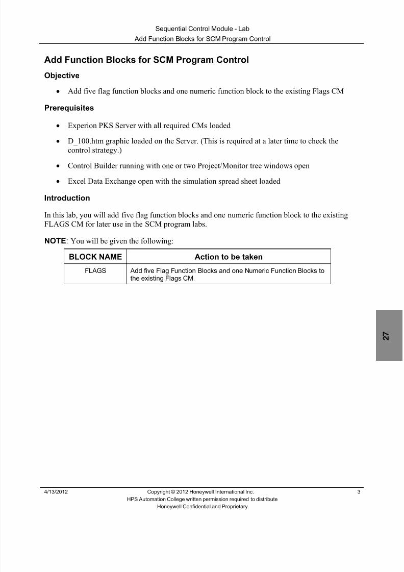
8/9/2019 Student Course Book- Automation
http://slidepdf.com/reader/full/student-course-book-automation 841/1165
Sequential Control Module - Lab
Add Function Blocks for SCM Program Control
4/13/2012 Copyright © 2012 Honeywell International Inc. 3
HPS Automation College written permission required to distributeHoneywell Confidential and Proprietary
Add Function Blocks for SCM Program Control
Objective
• Add five flag function blocks and one numeric function block to the existing Flags CM
Prerequisites
• Experion PKS Server with all required CMs loaded
• D_100.htm graphic loaded on the Server. (This is required at a later time to check thecontrol strategy.)
• Control Builder running with one or two Project/Monitor tree windows open
• Excel Data Exchange open with the simulation spread sheet loaded
IntroductionIn this lab, you will add five flag function blocks and one numeric function block to the existingFLAGS CM for later use in the SCM program labs.
NOTE : You will be given the following:
BLOCK NAME Action to be taken
FLAGS Add five Flag Function Blocks and one Numeric Function Blocks tothe existing Flags CM.

8/9/2019 Student Course Book- Automation
http://slidepdf.com/reader/full/student-course-book-automation 842/1165
Sequential Control Module - Lab
Add Function Blocks for SCM Program Control
4 Copyright © 2012 Honeywell International Inc. 4/13/2012
HPS Automation College written permission required to distributeHoneywell Confidential and Proprietary
Procedure
Add Function Blocks to FLAGS
Step Action
1 Open the Chart view of the CM called FLAGS in project window.
2 Add five Flags and one Numeric to the existing FLAGS CM.
Name the new flags P_START, F_MESSAGE, READY, P_ABORT andPROCESS .
Name the numeric FLOW.
Save and close FLAGS .
Load and activate FLAGS .

8/9/2019 Student Course Book- Automation
http://slidepdf.com/reader/full/student-course-book-automation 843/1165
Sequential Control Module - Lab
Specify SCM Recipe Values and Invoke Transition
4/13/2012 Copyright © 2012 Honeywell International Inc. 5
HPS Automation College written permission required to distributeHoneywell Confidential and Proprietary
Specify SCM Recipe Values and Invoke Transition
Objective
• Configure recipe values for later use in setting minimum flow level
• Configure the invoke transition
• Configure a step to turn on the Warning message
• Use a transition to check the Ready flag
• Configure a verify step, for later use, to allow the SCM to take separate paths
• Configure a Sync to allow the SCM to follow parallel paths
• Check and verify SCM program operation to this point
Prerequisites
• Experion PKS Server with all required CMs built and loaded
• D_100.htm graphic loaded on the Server (This is required at a later time to check the controlstrategy.)
• Control Builder running with one or two Project/Monitor tree windows open
• Excel Data Exchange open with simulation spread sheet loaded
• Previous SCM lab in this section complete, tested, and verified
Introduction
The process described in this lab is totally fictitious and created only to demonstrate SCM features .
In the first portion of this SCM program you will:
• Write a sequence that will do a fan switch check.
• Write and verify that the SCM will follow either of two routes based on the fan switchselection
• Use a set of Sync blocks to set up parallel sequence paths
• NOTE : You will configure the following:
BLOCK NAME Action to be takenSCM_D100 Write a step sequence to start circulation, and then initiate full process
flow.

8/9/2019 Student Course Book- Automation
http://slidepdf.com/reader/full/student-course-book-automation 844/1165
Sequential Control Module - Lab
Specify SCM Recipe Values and Invoke Transition
6 Copyright © 2012 Honeywell International Inc. 4/13/2012
HPS Automation College written permission required to distributeHoneywell Confidential and Proprietary
Create a SCM
Step Action
1 a. Build a new SCM into your project.b. Open the SCM in project chart view.
c. Open the configuration parameters window for this SCM.
d. Enter the following details on the Main tab:
Name: SCM_D100
Item Name: SCM_D100_Item
Description: Circulate / Process
Parent Asset: C11
2 On the Recipe Tab, right-click in the blank recipe area and select Append Row ).
Add three rows (recipe values) and configure them as follows:
Index Parameter Descriptor TargetValue
Target Hi Target lo
1 CIRCULATE_LOW_FLOW 47 100 0
2 CIRCULATE_LOW_FLOW_2 850 1750 0
3 CIRCULATE_LOW_FLOW_3 1 6 0
Accept the defaults for any other remaining parameters.Click OK .

8/9/2019 Student Course Book- Automation
http://slidepdf.com/reader/full/student-course-book-automation 845/1165
Sequential Control Module - Lab
Specify SCM Recipe Values and Invoke Transition
4/13/2012 Copyright © 2012 Honeywell International Inc. 7
HPS Automation College written permission required to distributeHoneywell Confidential and Proprietary
Step Action
3 a. Add one condition to the Invoke Transition.
b. Open the Transition for edit.
Enter the following:
Transition Name:
Start_Check
Transition Description:
Start Check
Condition 1 description:
Check Start Flag
Condition 1:
FLAGS.P_START.PVFL = 1
Primary Gate:
ConnectSecondary Gate:
Connect
Click OK
Condition
Description

8/9/2019 Student Course Book- Automation
http://slidepdf.com/reader/full/student-course-book-automation 846/1165
Sequential Control Module - Lab
Specify SCM Recipe Values and Invoke Transition
8 Copyright © 2012 Honeywell International Inc. 4/13/2012
HPS Automation College written permission required to distributeHoneywell Confidential and Proprietary
Step Action
4 a. Drag a STEP from the library into your project.
b. Add two Step outputs.
Enter the following:
Step Name:
M_ON
Step Description:
Message On
Output 1 Description :
ABORT FLAG OFF
Output 1 Expression:
FLAGS.P_ABORT.PVFL := 0
Output 2 Description:
START MESSAGE ONOutput 2 Expression :
FLAGS.F_MESSAGE.PVFL := 1
Click OK .
Wire the Transition above to this Step .
ATTENTION
From now on wire the Steps and Transitions, asneeded.
Output Expressions
Output Descriptions

8/9/2019 Student Course Book- Automation
http://slidepdf.com/reader/full/student-course-book-automation 847/1165
Sequential Control Module - Lab
Specify SCM Recipe Values and Invoke Transition
4/13/2012 Copyright © 2012 Honeywell International Inc. 9
HPS Automation College written permission required to distributeHoneywell Confidential and Proprietary
Step Action
5 a. Drag a Transition from the library into your project.
b. Enter the following:
Transition Name:
Check_Ready
Transition Description:
Check_Ready
Condition:
Create an expression that checks to see if FLAGS.READY is on.
Hint: See The Start_Check Transition in an earlier step for an example expression.
Description:
Check Ready Flag
Primary Gate:
ConnectSecondary Gate:
Connect

8/9/2019 Student Course Book- Automation
http://slidepdf.com/reader/full/student-course-book-automation 848/1165
Sequential Control Module - Lab
Specify SCM Recipe Values and Invoke Transition
10 Copyright © 2012 Honeywell International Inc. 4/13/2012
HPS Automation College written permission required to distributeHoneywell Confidential and Proprietary
Step Action
6 a. Drag a new STEP into your project.
b. Enter the following:
Step Name:
VERIFY
Step Description:
VERIFY
ATTENTION
Use this Step only as a decision point. No expressionneeded. One branch will continue to follow the processand the other branch will lead to an abort sequence.
7 a. Select the Block Pins Tab.
b. Add a second NEXTCOMP[2] pin at the Bottom .
c. Select the Block Preferences tab.
d. Check the View Pin Labels option.
e. Click OK .

8/9/2019 Student Course Book- Automation
http://slidepdf.com/reader/full/student-course-book-automation 849/1165
Sequential Control Module - Lab
Specify SCM Recipe Values and Invoke Transition
4/13/2012 Copyright © 2012 Honeywell International Inc. 11
HPS Automation College written permission required to distributeHoneywell Confidential and Proprietary
Step Action
8 a. Drag a Sync block into your project under the VERIFY step.
b. Wire from VERIFY NEXTCOMP[1] pin to the input of the Sync block.
c. Leave all parameters on the Sync block as default .

8/9/2019 Student Course Book- Automation
http://slidepdf.com/reader/full/student-course-book-automation 850/1165
Sequential Control Module - Lab
Specify SCM Recipe Values and Invoke Transition
12 Copyright © 2012 Honeywell International Inc. 4/13/2012
HPS Automation College written permission required to distributeHoneywell Confidential and Proprietary
Step Action
9 a. Drag two new Transitions into your project. Arrange them side by side under theSync block. ( See Step 13. )
b. Add four Expressions to each transition.
c. Enter the following in the left transition:
Transition Name:
CHECK_FANS
Transition Description:
CHECK_FANS
Create four conditions as described below:
Condition Description:
CHECK HS14A (through D).FLAGA = ON (Add similar descriptions to all fourexpressions).
Condition:
Create four expressions that check to see if 11_HS14A (through D).FLAGA.PVFL = ON (=1) .
Primary Gate:
AND (all four expressions to P1)
Secondary Gate:
Connect
Click OK .

8/9/2019 Student Course Book- Automation
http://slidepdf.com/reader/full/student-course-book-automation 851/1165
Sequential Control Module - Lab
Specify SCM Recipe Values and Invoke Transition
4/13/2012 Copyright © 2012 Honeywell International Inc. 13
HPS Automation College written permission required to distributeHoneywell Confidential and Proprietary
Step Action
10 Enter the following in the right transition:
Transition Name:
CHECK_FANS2
Transition Description:
CHECK_FANS2
Create four conditions as described below:
Condition Description:
CHECK HS14E (through H).FLAGA = ON (Add similar descriptions to all fourexpressions).
Condition:
Create four expressions that check to see if 11_HS14E (through H).FLAGA.PVFL = ON (=1)
Primary Gate:
AND (all four expressions to P1)Secondary Gate:
Connect
Click OK
11 a) Add a step under each of the transitions.
b) Add one output to each step.
c) Enter the following in the left step:
Step Name:
M_OFF
Step Description:
MESSAGE OFF
Output 1 Expression:
Write an expression that will turn Flags.F_MESSAGE OFF
Output 1 Description:
Warning message flag off
d) Enter the following in the right step:
Step Name:
S_FLAG_OStep Description:
START FLAG OFF
Output 1 Expression:
Write an expression that will turn FLAGS.P_START OFF
Output 1 Description:
Start Flag Off

8/9/2019 Student Course Book- Automation
http://slidepdf.com/reader/full/student-course-book-automation 852/1165
Sequential Control Module - Lab
Specify SCM Recipe Values and Invoke Transition
14 Copyright © 2012 Honeywell International Inc. 4/13/2012
HPS Automation College written permission required to distributeHoneywell Confidential and Proprietary
Step Action
12 a. Drag another Sync block into your project under the two Steps.
b. Make the name of this Sync block: SYNC_1
c. Remove NEXTCOMP[2] pin from the output of this Sync block.
d. Leave all parameters on the Sync block as default.
13 Wire the function blocks together, as shown below.
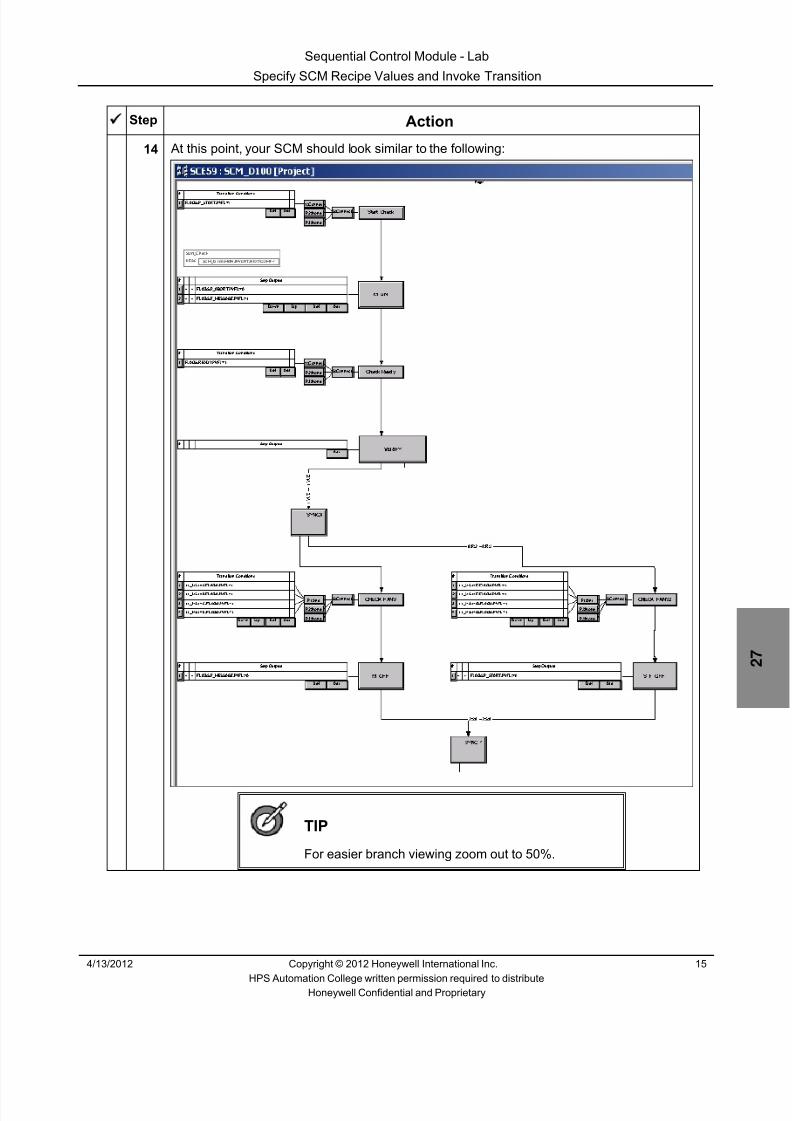
8/9/2019 Student Course Book- Automation
http://slidepdf.com/reader/full/student-course-book-automation 853/1165
Sequential Control Module - Lab
Specify SCM Recipe Values and Invoke Transition
4/13/2012 Copyright © 2012 Honeywell International Inc. 15
HPS Automation College written permission required to distributeHoneywell Confidential and Proprietary
Step Action
14 At this point, your SCM should look similar to the following:
TIP
For easier branch viewing zoom out to 50%.

8/9/2019 Student Course Book- Automation
http://slidepdf.com/reader/full/student-course-book-automation 854/1165
Sequential Control Module - Lab
Specify SCM Recipe Values and Invoke Transition
16 Copyright © 2012 Honeywell International Inc. 4/13/2012
HPS Automation College written permission required to distributeHoneywell Confidential and Proprietary
Step Action
15 Check the program.
a. Save the SCM, assign it to your CEE (CEESCEFB61 or SIM_CEEC300) and loadSCM_D100 .
b. Select the monitoring tab and make SCM_D100 active.
c. Make sure all CMs are loaded and active.
d. Verify the simulation spread sheet is running.
e. In Station, call up the graphic D_100 .
16 Change the CIRCULATE combo box to ON (this sets Flags.P_Start.PV = ON. This alsocauses PVFL to be ON which makes the condition for the invoke transition of SCM_D100 tobe true).
At the bottom of the display you should see that the Active Handler is SCM_D100.Main andthe Active Step is SCM_D100.M_ON .
You should also see the Warning message in the lower right corner of the display.
Click the Fan Control button.
You should now see the Fan Control Panel pop up display.
Leave any one fan switch in the OFF position and turn the rest of the fan switches to ONposition .

8/9/2019 Student Course Book- Automation
http://slidepdf.com/reader/full/student-course-book-automation 855/1165
Sequential Control Module - Lab
Specify SCM Recipe Values and Invoke Transition
4/13/2012 Copyright © 2012 Honeywell International Inc. 17
HPS Automation College written permission required to distributeHoneywell Confidential and Proprietary
Step Action
17 Select the SAFE combo box and change it to ON (this sets Flags.Ready.PV = ON. Thisalso causes PVFL to be ON).
The Program Active Step should now be SCM_D100.VERIFY .
18 Open Control Builder and view SCM_D100 in Monitoring mode and perform the following:• Verify that there are no red Steps or Transitions.• Verify that all the expressions in the CHECK_FANS and CHECK_FANS2
Transitions are green, except for the one that matches the fan switch that was leftin the OFF position.
19 Turn the other fan on and verify that the SCM completes.
20 If necessary to enforce understanding, run the SCM several more times.
To prepare the system, and run the SCM again:• From Station, on the D_100 display, turn both the CIRCULATE and the SAFE flags
OFF .• In Control Builder, change the state of SCM_D100 to IDLE .• Change the Mode Attribute of SCM_D100 to Operator and change the state to
IDLE .• Run the program
Run the SCM with at least one fan switch off.
The expected result is that the SCM stops at the VERIFY Step. (Only the first 3function blocks will be blue.)
Run the SCM with all fan switches on.
The expected result is that the SCM will complete execution through the last Syncblock. (Eight function blocks will be blue including the parallel transitions and steps.)
Fix any encountered problems.

8/9/2019 Student Course Book- Automation
http://slidepdf.com/reader/full/student-course-book-automation 856/1165
Sequential Control Module - Lab
Specify SCM Recipe Values and Invoke Transition
18 Copyright © 2012 Honeywell International Inc. 4/13/2012
HPS Automation College written permission required to distributeHoneywell Confidential and Proprietary
Step Action
21 When satisfied with your program:
Call up the D_100 graphic in Station and set the CIRCULATE and SAFE combo boxes toOFF .
In Control Builder, change the state of SCM_D100 to Idle , and inactivate it.
Change the Mode Attribute of SCM_D100 to Operator and change the state to IDLE .

8/9/2019 Student Course Book- Automation
http://slidepdf.com/reader/full/student-course-book-automation 857/1165
Sequential Control Module - Lab
Configure an SCM Abort Sequence
4/13/2012 Copyright © 2012 Honeywell International Inc. 19
HPS Automation College written permission required to distributeHoneywell Confidential and Proprietary
Configure an SCM Abort Sequence
Objective
• Configure an abort sequence
Prerequisites
• Experion PKS Server with all required CMs loaded
• D_100.htm graphic loaded on the Server. (This is required at a later time to check thecontrol strategy.)
• Control Builder running with one or two Project/Monitor tree windows open
• Excel Data Exchange open with the simulation spread sheet loaded
•
All previous SCM labs in this section completed, tested, and verifiedIntroduction
This part of the program will execute an abort sequence.
The process described in this lab is totally fictitious and created only to demonstrate SCMfeatures .
• In this portion of the SCM, you will add programming to turn off the Warning message andturn on an Abort Message
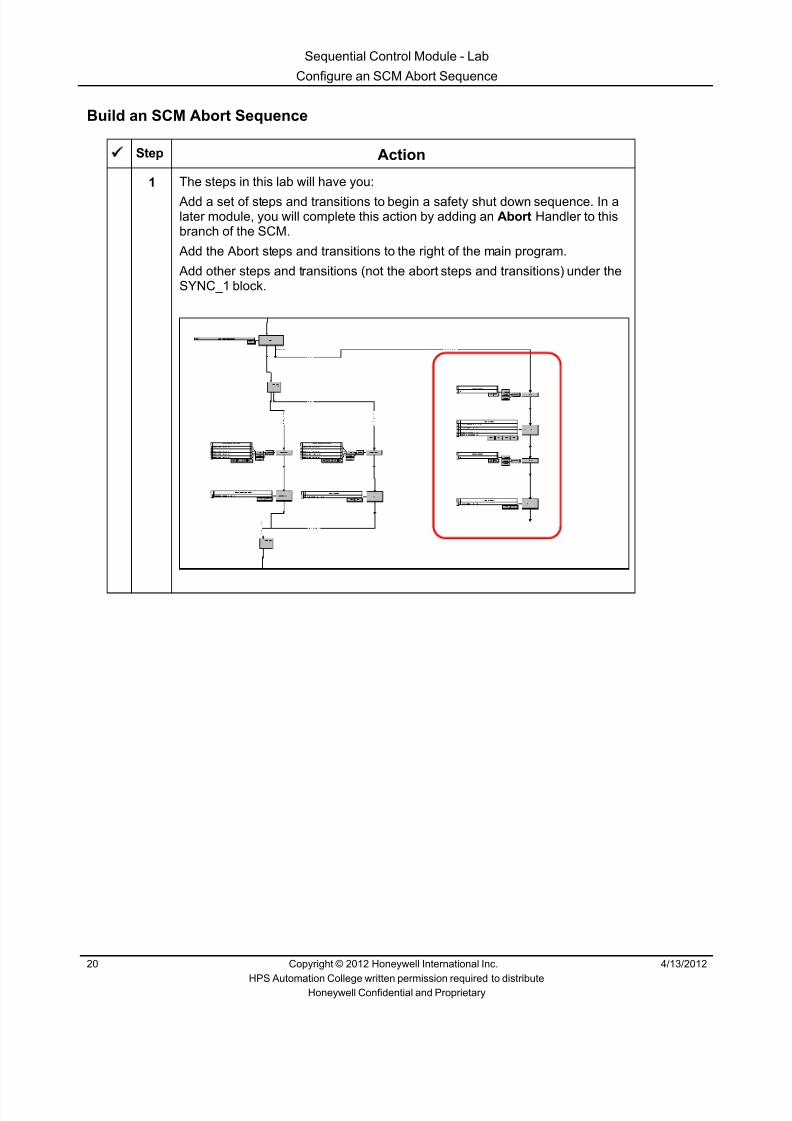
8/9/2019 Student Course Book- Automation
http://slidepdf.com/reader/full/student-course-book-automation 858/1165
Sequential Control Module - Lab
Configure an SCM Abort Sequence
20 Copyright © 2012 Honeywell International Inc. 4/13/2012
HPS Automation College written permission required to distributeHoneywell Confidential and Proprietary
Build an SCM Abort Sequence
Step Action
1 The steps in this lab will have you:
Add a set of steps and transitions to begin a safety shut down sequence. In alater module, you will complete this action by adding an Abort Handler to thisbranch of the SCM.
Add the Abort steps and transitions to the right of the main program.
Add other steps and transitions (not the abort steps and transitions) under theSYNC_1 block.

8/9/2019 Student Course Book- Automation
http://slidepdf.com/reader/full/student-course-book-automation 859/1165
Sequential Control Module - Lab
Configure an SCM Abort Sequence
4/13/2012 Copyright © 2012 Honeywell International Inc. 21
HPS Automation College written permission required to distributeHoneywell Confidential and Proprietary
Step Action
2 Open SCM_D100 in project view.
ATTENTION
Place this next Transition to the right of your mainprogram, as shown in the diagram above.
Drag a transition from the library into your project.
Add a condition to the transition.
Enter the following:
Transition Name:
DUMMY
Transition Description:
DUMMY
Condition Description:
DUMMY
Condition Expression:
1=1
Primary Gate:
Connect
Secondary Gate:
Connect
You must add a transition here because the sequence branched at a step. Inthis case, there was no useful action needed by this transition, so a dummywas used.
3 Connect and wire the NEXTCOMP[2] pin on the ‘Verify’ step to the Dummytransition you just added – as shown below:

8/9/2019 Student Course Book- Automation
http://slidepdf.com/reader/full/student-course-book-automation 860/1165

8/9/2019 Student Course Book- Automation
http://slidepdf.com/reader/full/student-course-book-automation 861/1165
Sequential Control Module - Lab
Configure an SCM Abort Sequence
4/13/2012 Copyright © 2012 Honeywell International Inc. 23
HPS Automation College written permission required to distributeHoneywell Confidential and Proprietary
Step Action
5 Add another dummy transition below the M_OFF_FAIL_ON Step.
Transition Name:
DUMMY2
Transition Description:
DUMMY2
6 Drag a STEP from the library into your project.
Add one Step output.
Enter the following:
Step Name:
ABORT_OFF
Step Description:
ABORT_OFF
Output 1 Description :Turn Abort Message OFF
Output 1 Expression:
Create an expression to turn off FLAGS.P_ABORT .
7 Program check:
Complete the wiring of the steps and transitions.
Save, close and load SCM_D100.
Select the monitoring tab and make SCM_D100 active.
Make sure all the other CMs are loaded and active.
Check the FLAGS CM and make sure all the contained flag function blocks areoff.In Station call up the graphic D_100.

8/9/2019 Student Course Book- Automation
http://slidepdf.com/reader/full/student-course-book-automation 862/1165
Sequential Control Module - Lab
Configure an SCM Abort Sequence
24 Copyright © 2012 Honeywell International Inc. 4/13/2012
HPS Automation College written permission required to distributeHoneywell Confidential and Proprietary
Step Action
8 Run the SCM as you did in the previous program check.
Verify the following:− When all fan switches are ON, the SCM executes the “normal” path
(through SYNCA).− When one or more of the fan switches are OFF, the SCM executes the
“abort” path (we just added).
After the sequence runs with at least one fan switch in the OFF position, themessage will indicate FAN FAILURE and PROGRAM ABORT. The ActiveStep will also be blank.
ATTENTION
The Fan Failure message will disappear after a fewseconds. The Active Step will also be blank.
9 When satisfied with your program:
From the D_100 graphic in Station, set the CIRCULATE and SAFE comboboxes to OFF .Change SCM_Pressure Mode Attribute to Operator, and change the state toIdle .
10 Inactivate SCM_D100.

8/9/2019 Student Course Book- Automation
http://slidepdf.com/reader/full/student-course-book-automation 863/1165
Sequential Control Module - Lab
Use a Step to Start Another SCM
4/13/2012 Copyright © 2012 Honeywell International Inc. 25
HPS Automation College written permission required to distributeHoneywell Confidential and Proprietary
Use a Step to Start Another SCM
Objective
• Configure SCM_D100 to start the SCM_Pressure program
Prerequisites
• Experion PKS Server with all required CMs loaded
• D_100.htm graphic loaded on the Server (This is required at a later time to check the controlstrategy.)
• Control Builder running with one or two Project/Monitor tree windows open
• Excel Data Exchange open with the simulation spread sheet loaded
• All previous SCM labs in this section completed, tested, and verified
Introduction
In this section of the program, you will modify SCM_D100 to cause it to start SCM_Pressure (the firstprogram you wrote).
The process described in this lab is totally fictitious and created only to demonstrate SCM features .
• Change the MODEATTR of SCM_Pressure to PROGRAM, and then start SCM_Pressure
• Check to see if 11_PC15 has reached 1240 Kpag
• Change the MODEATTR and MODE of selected points to be used later
• Check to see if 11_FC20 is closed

8/9/2019 Student Course Book- Automation
http://slidepdf.com/reader/full/student-course-book-automation 864/1165
Sequential Control Module - Lab
Use a Step to Start Another SCM
26 Copyright © 2012 Honeywell International Inc. 4/13/2012
HPS Automation College written permission required to distributeHoneywell Confidential and Proprietary
Continue with the Main Sequence
Step Action
1 For now, we are done with the Abort branch of the SCM.
You will add these next steps and transitions under the SYNC_1 block asshown below.
2
ATTENTION
Write expressions to start the program you built in aprevious module.
Drag a transition from the library onto the project chart view of SCM_D100.
Enter the following:
Transition Name:
CHECK_IDLE
Transition Description:
Your choice
Condition:
Create an expression that checks to see if SCM_PRESSURE.STATEis in the IDLE state.
Primary Gate:
As necessary
Secondary Gate:
As necessary

8/9/2019 Student Course Book- Automation
http://slidepdf.com/reader/full/student-course-book-automation 865/1165
Sequential Control Module - Lab
Use a Step to Start Another SCM
4/13/2012 Copyright © 2012 Honeywell International Inc. 27
HPS Automation College written permission required to distributeHoneywell Confidential and Proprietary
Step Action
3 Drag a STEP from the library into your project.
Position it under the CHECK_IDLE transition.
Add two Step Outputs.
Enter the following:
Step Name:
START_PRESS_P
Step Description:
START_PRESS_P
Output 1 Expression:
Create an expression that will change SCM_PRESSURE.MODEATTR to PROGRAM .
Output 1 Description :
SCM_Pressure Mode Attribute to PROGRAM
Output 2 Expression:
Create an expression that will change SCM_PRESSURE.COMMAND to Start .
Output 2 Description :
SCM_Pressure Start command
4 Drag a transition from the library into your project.
NOTE: One of the last actions that SCM_PRESSURE performs is changingthe setpoint of PC15 to 1240 KPag .
SCM_D100 should check that SCM_Pressure ran successfully by checkingthat PC15 PV is close to 1240.
Transition Name:
CHECK_PC15
Create a transition condition verifies that SCM_Pressure has completedexecuting by checking that PC15’s PV is between 1230 and 1250 KPag.
Add expressions as needed.
All other values:
Your choice

8/9/2019 Student Course Book- Automation
http://slidepdf.com/reader/full/student-course-book-automation 866/1165
Sequential Control Module - Lab
Use a Step to Start Another SCM
28 Copyright © 2012 Honeywell International Inc. 4/13/2012
HPS Automation College written permission required to distributeHoneywell Confidential and Proprietary
Step Action
5 Drag a STEP from the library into your project.
Add 16 Step Outputs.
Enter the following:
Step Name:
CIRCULATE
Create the expressions to do the following:
Change the MODEATTR of FC28, FC20, LC16, HC41, HC44 to PROGRAM
Change the MODE of FC28, FC20, LC16, HC41, HC44 to MAN
Change the OP of FC28, FC20, LC16, HC41, HC44 to 0.0
Change FLAGS.FLOW.PV to 20.0
Enforce Order Option:
AllOutputs
All other values:Your choice
ATTENTION
These points will be used in a later module.
6 Drag a transition from the library into your project.
Add expressions, as needed.Transition Name:
VALVE_CHECK
Create a Transition that assures FC20 is closed.
All other values:
Your choice
7 Wire all the transitions and steps.
8 Prepare to check your program:
From the D_100 graphic in Station, set the CIRCULATE and SAFE to OFF .
Turn all of the fans ON .In Control Builder, inactivate SCM_D100 .
Put SCM_PRESSURE Mode Attribute to Operator and the State in Idle.

8/9/2019 Student Course Book- Automation
http://slidepdf.com/reader/full/student-course-book-automation 867/1165

8/9/2019 Student Course Book- Automation
http://slidepdf.com/reader/full/student-course-book-automation 868/1165
Sequential Control Module - Lab
Use a Step to Start Another SCM
30 Copyright © 2012 Honeywell International Inc. 4/13/2012
HPS Automation College written permission required to distributeHoneywell Confidential and Proprietary
This page was intentionally left blank.
8/9/2019 Student Course Book- Automation
http://slidepdf.com/reader/full/student-course-book-automation 869/1165
Sequential Control Module - Lab
Use Recipe Values to Set Minimum Flow
4/13/2012 Copyright © 2012 Honeywell International Inc. 31
HPS Automation College written permission required to distributeHoneywell Confidential and Proprietary
Use Recipe Values to Set Minimum Flow
Objective
• Configure this SCM to use recipe values to set a minimum flow
Prerequisites:
• Experion PKS Server with all required CMs loaded
• D_100.htm graphic loaded on the Server (This is required at a later time to check the controlstrategy.)
• Control Builder running with one or two Project/Monitor tree windows open
• Excel Data Exchange open with the simulation spread sheet loaded
• All previous SCM labs in this section completed, tested, and verified

8/9/2019 Student Course Book- Automation
http://slidepdf.com/reader/full/student-course-book-automation 870/1165
Sequential Control Module - Lab
Use Recipe Values to Set Minimum Flow
32 Copyright © 2012 Honeywell International Inc. 4/13/2012
HPS Automation College written permission required to distributeHoneywell Confidential and Proprietary
Turn Circulation on and Set Flow Level
Step Action
1 Open SCM_D100 in project view.
Drag a STEP from the library into your project and place it under theVALVE_CHECK Transition.
Add 15 Step Outputs
Add a NEXTCOMP[2] pin to the bottom of this step.
Enter the following:
Step Name:
CIRCULATE2
Create the expressions to do the following:
Change the MODEATTR of AC12, FC28, FC19, PC15, PC16 to PROGRAM
Change the MODE of AC12, FC28, PC15, PC16 to AUTO
Change the MODE of FC19 to CAS
Change the SP of AC12 to SCM_D100.RECTARGET[3] (This is the RecipeTarget Value number 3)
Change the SPs of PC15 and PC16 to a value that is equal to Recipe TargetValue 2 plus 700.0 (Do this math within the Step Output expression.Do not change the recipe Target Value.)
Turn HS62.FLAGA ON
Turn HS68.FLAGA OFF
Enforce Order Option:
AllOutputs
All other values:Your choice

8/9/2019 Student Course Book- Automation
http://slidepdf.com/reader/full/student-course-book-automation 871/1165
Sequential Control Module - Lab
Use Recipe Values to Set Minimum Flow
4/13/2012 Copyright © 2012 Honeywell International Inc. 33
HPS Automation College written permission required to distributeHoneywell Confidential and Proprietary
Step Action
2 Wire the output of CIRCULATE2 NEXTCOMP[2] pin back to the input of theVALVE_CHECK Transition. You will also need to temporarily wire theNEXTCOMP[1] pin back to the input of the VALVE_CHECK Transition so that
you can do the program check in the next step.
3 Program Check List:
Save, load, activate and run your program.
If one or more fan switches are in the OFF position, your program shouldfollow the Abort sequence.
If all the fan switches are ON , then your program should start theSCM_PRESSURE program (assuming it is in IDLE and ready to go). Next, theprogram should execute the CM changes indicated in the Circulate step.Once your program completes the CIRCULATE2 Step, it will branch back tothe VALVE_CHECK Transition continuously. This allows you to set thecirculate flow amounts by adjusting the Recipe Target Values.
4 When satisfied with your program:
Call up the D_100 graphic in Station and set the CIRCULATE and SAFE combo boxes to OFF .
In Control Builder, inactivate SCM_D100 .
Put SCM_PRESSURE Mode Attribute to Operator and the State in Idle.
VALVE_CHECK
CIRCULATE2

8/9/2019 Student Course Book- Automation
http://slidepdf.com/reader/full/student-course-book-automation 872/1165
Sequential Control Module - Lab
Use Recipe Values to Set Minimum Flow
34 Copyright © 2012 Honeywell International Inc. 4/13/2012
HPS Automation College written permission required to distributeHoneywell Confidential and Proprietary
This page was intentionally left blank.

8/9/2019 Student Course Book- Automation
http://slidepdf.com/reader/full/student-course-book-automation 873/1165
Sequential Control Module - Lab
Interface an SCM with a Graphic Textbox
4/13/2012 Copyright © 2012 Honeywell International Inc. 35
HPS Automation College written permission required to distributeHoneywell Confidential and Proprietary
Interface an SCM with a Graphic Textbox
Objective
• Configure the SCM to accept input values from the Process Flow textbox on the D_100
graphic
Prerequisites
• Experion PKS Server with all required CMs loaded
• D_100.htm graphic loaded on the Server (This is required at a later time to check the controlstrategy.)
• Control Builder running with one or two Project/Monitor tree windows open
• Excel Data Exchange open with the simulation spread sheet loaded
• All previous SCM labs in this section completed, tested, and verified
Introduction
In this section of the SCM, you will write programming to tie the value in the Process Flow textbox(on the D_100 graphic) to the SPs of several controllers.
The process described in this lab is totally fictitious and created only to demonstrate SCMfeatures .
• Create algorithms that convert the Process Flow textbox to a SP value in engineering unit,for several controllers.

8/9/2019 Student Course Book- Automation
http://slidepdf.com/reader/full/student-course-book-automation 874/1165
Sequential Control Module - Lab
Interface an SCM with a Graphic Textbox
36 Copyright © 2012 Honeywell International Inc. 4/13/2012
HPS Automation College written permission required to distributeHoneywell Confidential and Proprietary
Add the Process Sequence
Step Action
1 Open the SCM_D100 project chart view.
Delete the wire connection from CIRCULATE2 NEXTCOMP[1] to the input ofthe VALVE_CHECK transition. Leave the NEXTCOMP[2] connection as is.
Drag a transition from the library into your project and place it under theCIRCULATE2 step.
Add expressions as needed.
Transition Name:
PROCESS
Create a transition that checks to see if FLAGS.PROCESS is ON .
All other values:
Your choice
2 On the D-100 display, is a field named “Process Flow” (the actual parameter isFlags.Flow.PV). The operator can enter a “Process Flow” from 0 – 100. Thisvalue represents the percent of range in which the process will operate. Forexample, if the operator enters 75, the SP of a tag will be changed to 75% ofrange. This step, and the next step will accomplish that.
a. Drag a STEP from the library into your project and place it under thePROCESS Transition.
b. Add Step Outputs as necessary
(Count the number of expressions required by this step (2) ANDthe next step (4).)
c. Enter the following:Step Name:
RUN_PROCESS
Create the expressions to do the following:
Change the MODEATTR of FC20, LC16 to PROGRAM
Change the MODE of FC20 to CAS
Change the MODE of LC16 to AUTO
Turn HS68 FlagA ON . (Use 11_HS68.FlagA.PVFL)

8/9/2019 Student Course Book- Automation
http://slidepdf.com/reader/full/student-course-book-automation 875/1165
Sequential Control Module - Lab
Interface an SCM with a Graphic Textbox
4/13/2012 Copyright © 2012 Honeywell International Inc. 37
HPS Automation College written permission required to distributeHoneywell Confidential and Proprietary
Step Action
3 Create expressions which will calculate values based on “Process Flow”(Flags.Flow.PV) as shown below:
PC15 and PC16 are reverse acting controllers. Use the following expressionsto calculate their SPs:
11_PC15.PIDA.SP := (1050.0-(11_PC15.PIDA.PVEUHI-11_PC15.PIDA.PVEULO)*(FLAGS.FLOW.PV/100.0)) +11_PC15.PIDA.PVEULO
11_PC16.PIDA.SP := (1050.0-(11_PC16.PIDA.PVEUHI-11_PC16.PIDA.PVEULO)*(FLAGS.FLOW.PV/100.0)) +11_PC16.PIDA.PVEULO
FC28 and LC16 are direct acting controllers. Use the following expressions to
calculate their SPs:11_FC28.PIDA.SP := ((11_FC28.PIDA.PVEUHI-11_FC28.PIDA.PVEULO)*(FLAGS.FLOW.PV/100.0)) +11_FC28.PIDA.PVEULO
11_LC16.PIDA.SP := ((11_LC16.PIDA.PVEUHI-11_LC16.PIDA.PVEULO)*(FLAGS.FLOW.PV/100.0)) +11_LC16.PIDA.PVEULO
Calculate AC12 SP based on the SP High and SP Low limits (rather than therange of the tag). Use the following expression to calculate the SP:
11_AC12.PIDA.SP := ((11_AC12.PIDA.SPHILM-11_AC12.PIDA.SPLOLM)*(FLAGS.FLOW.PV/100.0)) +11_AC12.PIDA.SPLOLM
Use the following expressions to vary the OP of 11_HC41 and 11_HC44 inproportion to FLAGS.FLOW:
11_HC41.AUTOMANA.OP := ((11_HC41.AUTOMANA.XEUHI-11_HC41.AUTOMANA.XEULO)*(FLAGS.FLOW.PV/100.0)) +11_HC41.AUTOMANA.XEULO
11_HC44.AUTOMANA.OP := ((11_HC44.AUTOMANA.XEUHI-11_HC44.AUTOMANA.XEULO)*(FLAGS.FLOW.PV/100.0)) +
11_HC44.AUTOMANA.XEULO

8/9/2019 Student Course Book- Automation
http://slidepdf.com/reader/full/student-course-book-automation 876/1165
Sequential Control Module - Lab
Interface an SCM with a Graphic Textbox
38 Copyright © 2012 Honeywell International Inc. 4/13/2012
HPS Automation College written permission required to distributeHoneywell Confidential and Proprietary
Step Action
4 Wire the RUN_PROCESS NEXTCOMP[1] pin back to the input of thePROCESS Transition.
VALVE_CHECK
CIRCULATE2
PROCESS
RUN_PROCESS

8/9/2019 Student Course Book- Automation
http://slidepdf.com/reader/full/student-course-book-automation 877/1165
Sequential Control Module - Lab
Interface an SCM with a Graphic Textbox
4/13/2012 Copyright © 2012 Honeywell International Inc. 39
HPS Automation College written permission required to distributeHoneywell Confidential and Proprietary
Step Action
5 Program Check:
Save, load, activate, and run your program.
If one or more fan switches are in the OFF position, your program shouldfollow the Abort sequence.
If all the fan switches are ON , then your program should start theSCM_PRESSURE program (assuming it is in IDLE and ready to go).
Once your program completes the CIRCULATE2 step, it will branch back tothe VALVE_CHECK transition continuously until the PROCESS flag is turnedON.
When your program reaches the CIRCULATE2 step, select and changePROCESS combo box to ON .
You should now be able to select and change the amount of flow in thePROCESS FLOW textbox in the lower right of the D_100 graphic, and see theprocess respond accordingly.
Set Process Flow to 30%. Verify that the SPs and OPs of the tags werecalculated and stored successfully:
PC15.SP and PC16.SP = 1435
FC28.SP = 46.50
LC16.SP = 30
AC12.SP = 0.6
HC41.OP and HC44.OP = 30 (look on Debutanizer_123)
Set Process Flow to 50%. Verify that the SPs and OPs of the tags werecalculated and stored successfully:
PC15.SP and PC16.SP = 1225
FC28.SP = 77.50
LC16.SP = 50
AC12.SP = 1.0
HC41.OP and HC44.OP = 50 (look on Debutanizer_123)
Try setting the Process Flow to other values. Setting the flow above 75% willput a flame in the Flare Cam screen. Setting the flow above 95% will causethe compressor to explode.
6 When you are satisfied with your program:
Call up the D_100 graphic in Station and set the CIRCULATE, SAFE, andPROCESS combo boxes to OFF .
In Control Builder, inactivate SCM_D100 .
Put SCM_PRESSURE Mode Attribute to Operator and the State in Idle.

8/9/2019 Student Course Book- Automation
http://slidepdf.com/reader/full/student-course-book-automation 878/1165
Sequential Control Module - Lab
Interface an SCM with a Graphic Textbox
40 Copyright © 2012 Honeywell International Inc. 4/13/2012
HPS Automation College written permission required to distributeHoneywell Confidential and Proprietary
This page was intentionally left blank.

8/9/2019 Student Course Book- Automation
http://slidepdf.com/reader/full/student-course-book-automation 879/1165
1
1
Honeywell ConfidentialCopyright © 2012 Honeywell International Inc.
4/13/2012
Describe Interactive Instructions
Interactive Instructions Describe Interactive InstructionsInteractive Instructions Describe Interactive Instructions
Honeywell
Honeywell ConfidentialCopyright © 2012 Honeywell International Inc.
4/13/20122
Introduction
• In this lesson you will learn tooperate and configure InteractiveInstructions for a SequentialControl Module (SCM)
• At the conclusion of this lesson,you will know how to:
– Navigate Table View
– Operate an SCM Using TableView
– Configure an SCM for informedoperation
Interactive Instructions Describe Interactive Instructions

8/9/2019 Student Course Book- Automation
http://slidepdf.com/reader/full/student-course-book-automation 880/1165
2
Honeywell
Honeywell ConfidentialCopyright © 2012 Honeywell International Inc.
4/13/20123
Topics
•
Navigating Table View• Operating an SCM in Table View
• Configuring an SCM for Informed Operation in Table View
Interactive Instructions Describe Interactive Instructions
Honeywell
Honeywell ConfidentialCopyright © 2012 Honeywell International Inc.
4/13/20124
Chart View and Table View
• Chart View• Table View
Chart or TableView Toggle
Interactive Instructions Describe Interactive Instructions

8/9/2019 Student Course Book- Automation
http://slidepdf.com/reader/full/student-course-book-automation 881/1165
3
Honeywell
Honeywell ConfidentialCopyright © 2012 Honeywell International Inc.
4/13/20125
SCM Table View Structure
SummaryPane
SCM’s Phase,Step/ Transition
Detail Pane
AdditionalDetail Pane
MinitrendPane
KeyParameters
Pane
Interactive Instructions Describe Interactive Instructions
Honeywell
Honeywell ConfidentialCopyright © 2012 Honeywell International Inc.
4/13/20126
Question 1: Table View
Incorrect. The Table view is another way to view andoperate SCMs.
Click anywhere to continue.
Incorrect. The Table view is another way to view andoperate SCMs.
Click anywhere to continue.
Correct! The Table view is another way to view andoperate SCMs.
Click anywhere to continue.
Incorrect. The Table view is another way to view andoperate SCMs.
Click anywhere to continue.
Correct - Click anywhere to continueIncorrect - Click anywhere to continueYou answered this correctly!
Your answer: The correct answer is:
You did not answer this question completelyYou must answer the question beforecontinuing
Submit Clear
Control Builder table view: A) Is used by operators to sign on to
Experion
B) Is an SCM as viewed in aspreadsheet
C) Is another way to view andoperate SCMs
D) Requires video camera
Interactive Instructions Describe Interactive Instructions

8/9/2019 Student Course Book- Automation
http://slidepdf.com/reader/full/student-course-book-automation 882/1165
4
Honeywell
Honeywell ConfidentialCopyright © 2012 Honeywell International Inc.
4/13/20127
Topics
•
Navigating Table View• Operating an SCM in Table View
• Configuring an SCM for Informed Operation in Table View
Interactive Instructions Describe Interactive Instructions
Honeywell
Honeywell ConfidentialCopyright © 2012 Honeywell International Inc.
4/13/20128
Interactive Instructions – Operation Buttons
Chart View Automatic Tracking
Go to Selected Step
SCM Command
Expand/Collapse Instructions
Bypass Output
Instruction Filter
CompletedFilter
Flow/List View
Filters and SettingsPrint Option
Interactive Instructions Describe Interactive Instructions

8/9/2019 Student Course Book- Automation
http://slidepdf.com/reader/full/student-course-book-automation 883/1165
5
Honeywell
Honeywell ConfidentialCopyright © 2012 Honeywell International Inc.
4/13/20129
Interactive Instruction - Table View (Flow/List View)
• List View• Flow View List/Flow View selection
Interactive Instructions Describe Interactive Instructions
Honeywell
Honeywell ConfidentialCopyright © 2012 Honeywell International Inc.
4/13/201210
Interactive Instructions – Step Symbols
Interactive Instructions Describe Interactive Instructions

8/9/2019 Student Course Book- Automation
http://slidepdf.com/reader/full/student-course-book-automation 884/1165
6
Honeywell
Honeywell ConfidentialCopyright © 2012 Honeywell International Inc.
4/13/201211
Interactive Instructions – Step Symbols
Interactive Instructions Describe Interactive Instructions
Honeywell
Honeywell ConfidentialCopyright © 2012 Honeywell International Inc.
4/13/201212
Step and Transition Box ColorsStep Execution Status (Box Color):
White – Step is not yet started
Green – Step is executing
Teal – Step complete, waiting for trailingtransition
Dark blue – Step has been executed
Yellow – Step execution has started andwarning exists
Red – Step execution has started anderror exists
Magenta – Some outputs were notcompleted when the step was left
Transition Status (Box Color):
White – Transition is not yet active orcomplete
Green – This transition is currentlyactive
Red – an error exists in one of thetransition conditions
Interactive Instructions Describe Interactive Instructions

8/9/2019 Student Course Book- Automation
http://slidepdf.com/reader/full/student-course-book-automation 885/1165
7
Honeywell
Honeywell ConfidentialCopyright © 2012 Honeywell International Inc.
4/13/201213
Interactive Instruction – Table View Details
Click onstep
ConfirmableInstruction
Step outputsshow in details
pane
Interactive Instructions Describe Interactive Instructions
Honeywell
Honeywell ConfidentialCopyright © 2012 Honeywell International Inc.
4/13/201214
Interactive Instructions – Details
Monitor TaskParameter
Current Parameter
Interactive Instructions Describe Interactive Instructions
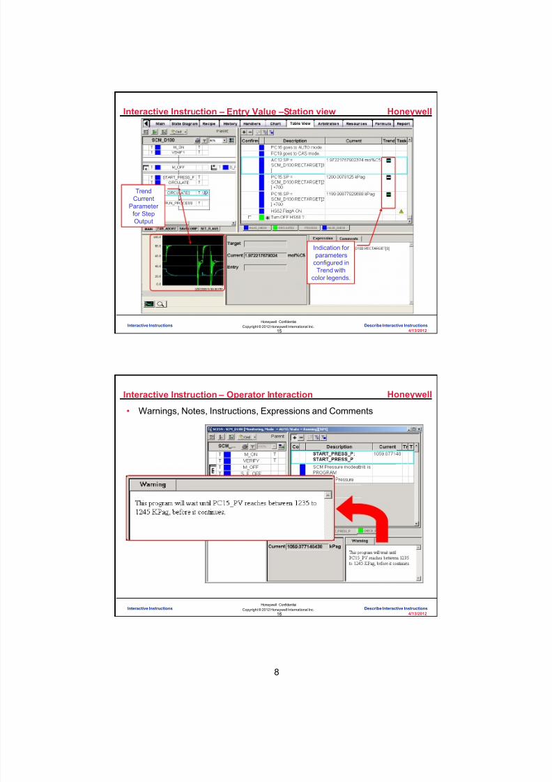
8/9/2019 Student Course Book- Automation
http://slidepdf.com/reader/full/student-course-book-automation 886/1165
8
Honeywell
Honeywell ConfidentialCopyright © 2012 Honeywell International Inc.
4/13/201215
Interactive Instruction – Entry Value –Station view
Indication forparameters
configured inTrend with
color legends.
TrendCurrent
Parameterfor StepOutput
Interactive Instructions Describe Interactive Instructions
Honeywell
Honeywell ConfidentialCopyright © 2012 Honeywell International Inc.
4/13/201216
Interactive Instruction – Operator Interaction
• Warnings, Notes, Instructions, Expressions and Comments
Interactive Instructions Describe Interactive Instructions

8/9/2019 Student Course Book- Automation
http://slidepdf.com/reader/full/student-course-book-automation 887/1165
9
Honeywell
Honeywell ConfidentialCopyright © 2012 Honeywell International Inc.
4/13/201217
Topics
•
Navigating Table View• Operating an SCM in Table View
• Configuring an SCM for Informed Operation in Table View
Interactive Instructions Describe Interactive Instructions
Honeywell
Honeywell ConfidentialCopyright © 2012 Honeywell International Inc.
4/13/201218
Interactive Instructions – Main Tab Step Configuration
Step Configuration Main Tab•Edit Warning/Note•Enforce Order •Step-Level Confirmation
Interactive Instructions Describe Interactive Instructions

8/9/2019 Student Course Book- Automation
http://slidepdf.com/reader/full/student-course-book-automation 888/1165
10
Honeywell
Honeywell ConfidentialCopyright © 2012 Honeywell International Inc.
4/13/201219
Interactive Instructions – Step Settings Configuration
Interactive Instructions Describe Interactive Instructions
Honeywell
Honeywell ConfidentialCopyright © 2012 Honeywell International Inc.
4/13/201220
Interactive Instructions – Output Instruction Tab
Output Instruction Tab-Instruction Type-Target Parameter -Current Parameter -Entry Parameter -Monitor Task-Role
Interactive Instructions Describe Interactive Instructions

8/9/2019 Student Course Book- Automation
http://slidepdf.com/reader/full/student-course-book-automation 889/1165
11
Honeywell
Honeywell ConfidentialCopyright © 2012 Honeywell International Inc.
4/13/201221
Interactive Instructions – Output Instruction Tab
Interactive Instructions Describe Interactive Instructions
Honeywell
Honeywell ConfidentialCopyright © 2012 Honeywell International Inc.
4/13/201222
Interactive Instructions – Output Instruction Tab - Trend
Interactive Instructions Describe Interactive Instructions

8/9/2019 Student Course Book- Automation
http://slidepdf.com/reader/full/student-course-book-automation 890/1165
12
Honeywell
Honeywell ConfidentialCopyright © 2012 Honeywell International Inc.
4/13/201223
Interactive Instructions – Output Advanced Tab
• Output Advanced Tab – Target value description – Maximum value of target – Minimum value of target – Engineering units descriptor
for target
– Description of current value – Engineering units descriptor
for current value
– Description for entry value – Maximum value of entry
value – Minimum value of entry
value – Engineering units descriptor
for entry value
Interactive Instructions Describe Interactive Instructions
Honeywell
Honeywell ConfidentialCopyright © 2012 Honeywell International Inc.
4/13/201224
Interactive Instructions – HTML Editor
HTML Editor • Edit in HTML or Text• Appearance
• Font• Color • Size
• Link to:• SOP• Intranet
Interactive Instructions Describe Interactive Instructions

8/9/2019 Student Course Book- Automation
http://slidepdf.com/reader/full/student-course-book-automation 891/1165
13
Honeywell
Honeywell ConfidentialCopyright © 2012 Honeywell International Inc.
4/13/201225
Question 2: SCM Expressions
Correct! SCM Expressions cannot be used with aconfirmable message.
Click anywhere to continue.
Incorrect. SCM Expressions cannot be used with aconfirmable message.
Click anywhere to continue.
Incorrect. SCM Expressions cannot be used with aconfirmable message.
Click anywhere to continue.
Incorrect. SCM Expressions cannot be used with aconfirmable message.
Click anywhere to continue.
Correct - Click anywhere to continueIncorrect - Click anywhere to continueYou answered this correctly!
Your answer: The correct answer is:
You did not answer this question completelyYou must answer the question beforecontinuing
Submit Clear
SCM Expressions: A) Cannot be used with a confirmable message
B) Cannot be used to command an SP message
C) Are not permitted to used in a step output
D) Must ask a question
Interactive Instructions Describe Interactive Instructions
Honeywell
Honeywell ConfidentialCopyright © 2012 Honeywell International Inc.
4/13/201226
Summary
• Table View:
– Can be viewed and operated in Control Builder
– Is another way to view and control an SCM
– Allows the operator to interact with the SCM by giving the SCM commands,bypassing outputs and confirming outputs
– Is configured in control builder on the Main and Output tabs in Step functionblocks
Interactive Instructions Describe Interactive Instructions

8/9/2019 Student Course Book- Automation
http://slidepdf.com/reader/full/student-course-book-automation 892/1165
14
Honeywell
Honeywell ConfidentialCopyright © 2012 Honeywell International Inc.
4/13/201227
Lab Examples – 1 of 4
• Configure Target, Entry and Current Parameters
Interactive Instructions Describe Interactive Instructions
Honeywell
Honeywell ConfidentialCopyright © 2012 Honeywell International Inc.
4/13/201228
Lab Examples – 2 of 4
• Configure an SCM Abort Handler
Interactive Instructions Describe Interactive Instructions

8/9/2019 Student Course Book- Automation
http://slidepdf.com/reader/full/student-course-book-automation 893/1165
15
Honeywell
Honeywell ConfidentialCopyright © 2012 Honeywell International Inc.
4/13/201229
Lab Examples – 3 of 4
• Configure an SCM Interrupt Handler
Interactive Instructions Describe Interactive Instructions
Honeywell
Honeywell ConfidentialCopyright © 2012 Honeywell International Inc.
4/13/201230
Lab Examples – 4 of 4
• Configure an SCM Check Handler
Interactive Instructions Describe Interactive Instructions

8/9/2019 Student Course Book- Automation
http://slidepdf.com/reader/full/student-course-book-automation 894/1165
16
Honeywell
Honeywell ConfidentialCopyright © 2012 Honeywell International Inc.
4/13/201231
Conclusion
CompletionCertificate
Proceed to the Configure Target, Entry and Current Parameters and Configurean SCM Abort Handler , Interrupt Handler and Check Handler lab exercises
Describe Interactive Instructions
Interactive Instructions Describe Interactive Instructions
Honeywell
Honeywell ConfidentialCopyright © 2012 Honeywell International Inc.
4/13/201232
This page intentionally left blank
Interactive Instructions Describe Interactive Instructions

8/9/2019 Student Course Book- Automation
http://slidepdf.com/reader/full/student-course-book-automation 895/1165
4/13/2012 Copyright © 2012 Honeywell International Inc. 1
HPS Automation College written permission required to distributeHoneywell Confidential and Proprietary
Topic: Interactive Instructions
Contents
Configure Interactive Instructions .......................................................................................................... 3

8/9/2019 Student Course Book- Automation
http://slidepdf.com/reader/full/student-course-book-automation 896/1165
2 Copyright © 2012 Honeywell International Inc. 4/13/2012
HPS Automation College written permission required to distributeHoneywell Confidential and Proprietary
This page was intentionally left blank.
8/9/2019 Student Course Book- Automation
http://slidepdf.com/reader/full/student-course-book-automation 897/1165
Interactive Instructions
Configure Interactive Instructions
4/13/2012 Copyright © 2012 Honeywell International Inc. 3
HPS Automation College written permission required to distributeHoneywell Confidential and Proprietary
Configure Interactive Instructions
Objective
• Configure Target and Entry values for Interactive Instructions
• Configure advanced tabs, trend items, etc.
Prerequisites
• Experion Server with all required CMs built and loaded
• D_100.htm graphic loaded on the Server. (This is required at a later time to check thecontrol strategy.)
• Control Builder running with one or two Project/Monitor tree windows open
• Excel Data Exchange open with the simulation spread sheet loaded• All previous labs in this section completed, tested, and verified
Introduction
In this module you will configure target, entry, and current values to inform and help the operator tocontrol the process.
The process described in this lab is totally fictitious and created only to demonstrate SCM
features .

8/9/2019 Student Course Book- Automation
http://slidepdf.com/reader/full/student-course-book-automation 898/1165
Interactive Instructions
Configure Interactive Instructions
4 Copyright © 2012 Honeywell International Inc. 4/13/2012
HPS Automation College written permission required to distributeHoneywell Confidential and Proprietary
Configure SCMs for Interactive Instructions
Step Action
1 When SCM_D100 reaches the CHECK_PC15 transition, the SCM waits until11_PC15’s PV is between 1230 and 1250 KPag. It will appear to the operatorthat the program is held at the step START_PRESS_P even though it’s theCHECK_PC15 transition that is causing the wait. This step will configure aCurrent Parameter to allow the operator to monitor PC15 PV.
a. Open SCM_D100 in Project view.
b. Configure the Current Parameter of the START_PRESS_P step todisplay the PV of 11_PC15 (shown below).
c. Check the Trend Current Parameter checkbox.
TIP
The ‘Current Description’ and the ‘Current EUDescription’ are automatically filled in.

8/9/2019 Student Course Book- Automation
http://slidepdf.com/reader/full/student-course-book-automation 899/1165
Interactive Instructions
Configure Interactive Instructions
4/13/2012 Copyright © 2012 Honeywell International Inc. 5
HPS Automation College written permission required to distributeHoneywell Confidential and Proprietary
Step Action
2 Configure a Warning that explains to the operator what the current value isand why the program is waiting, at this point.
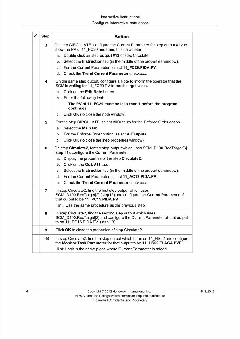
8/9/2019 Student Course Book- Automation
http://slidepdf.com/reader/full/student-course-book-automation 900/1165
Interactive Instructions
Configure Interactive Instructions
6 Copyright © 2012 Honeywell International Inc. 4/13/2012
HPS Automation College written permission required to distributeHoneywell Confidential and Proprietary
Step Action
3 On step CIRCULATE, configure the Current Parameter for step output #12 toshow the PV of 11_FC20 and trend this parameter:
a. Double click on step output #12 of step Circulate.
b. Select the Instruction tab (in the middle of the properties window).
c. For the Current Parameter, select 11_FC20.PIDA.PV .
d. Check the Trend Current Parameter checkbox.
4 On the same step output, configure a Note to inform the operator that theSCM is waiting for 11_FC20 PV to reach target value.
a. Click on the Edit Note button.
b. Enter the following text:
The PV of 11_FC20 must be less than 1 before the programcontinues.
c. Click OK (to close the note window).
5 For the step CIRCULATE, select AllOutputs for the Enforce Order option.
a. Select the Main tab.
b. For the Enforce Order option, select AllOutputs .
c. Click OK (to close the step properties window)
6 On step Circulate2 , for the step output which uses SCM_D100.RecTarget[3](step 11), configure the Current Parameter:
a. Display the properties of the step Circulate2 .
b. Click on the Out. #11 tab.
c. Select the Instruction tab (in the middle of the properties window).
d. For the Current Parameter, select 11_AC12.PIDA.PV .e. Check the Trend Current Parameter checkbox.
7 In step Circulate2, find the first step output which usesSCM_D100.RecTarget[2] (step12) and configure the Current Parameter ofthat output to be 11_PC15.PIDA.PV .
Hint: Use the same procedure as the previous step.
8 In step Circulate2, find the second step output which usesSCM_D100.RecTarget[2] and configure the Current Parameter of that outputto be 11_PC16.PIDA.PV. (step 13)
9 Click OK to close the properties of step Circulate2.
10 In step Circulate2, find the step output which turns on 11_HS62 and configurethe Monitor Task Parameter for that output to be 11_HS62.FLAGA.PVFL .
Hint: Look in the same place where Current Parameter is added.

8/9/2019 Student Course Book- Automation
http://slidepdf.com/reader/full/student-course-book-automation 901/1165
Interactive Instructions
Configure Interactive Instructions
4/13/2012 Copyright © 2012 Honeywell International Inc. 7
HPS Automation College written permission required to distributeHoneywell Confidential and Proprietary
Step Action
11 In step Circulate2, between outputs 14 & 15, add a step output which sends amessage to the operator. The message must require confirmation.
a. Add blank step out between step out #14 and 15 of the Circulate2 step.
b. Double click on the new step.
c. Select the Instruction tab (in the middle of the properties window).
d. Select Confirm for the Instruction Type.
e. Click the Edit Instruction button.
f. Enter the following instruction for the operator:From the D_100 display, turn on the PROCESS flag. Then return tothis display and Confirm this message (by clicking on thecheckbox) for the program to proceed.
g. Click OK (to close the Instruction entry window).
h. Click OK to close the properties of the Circulate2 step.
12 Make the following change to the PROCESS transition:a. Change this transition to a dummy. (condition 1 = 1)
13 In step Run_Process, find the step output which sets 11_PC15.PIDA.SP andconfigure the Current Parameter of that output to be 11_PC15.PIDA.PV .
14 In step Run_Process, find the step output which sets 11_PC16.PIDA.SP andconfigure the Current Parameter of that output to be 11_PC16.PIDA.PV .
15 In step Run_Process, find the step output which sets 11_FC28.PIDA.SP andconfigure the Current Parameter of that output to be 11_FC28.PIDA.PV .
16 In step Run_Process, find the step output which sets 11_LC16.PIDA.SP andconfigure the Current Parameter of that output to be 11_LC16.PIDA.PV .
17 Later in the lab, you will be entering a value for Flags.Flow.PV. This step willconfigure the SCM (table view – interactive instructions) to allow an operatorto enter a value which will be stored into Flags.Flow.PV at runtime. Note: Onthe D_100 display, the field named “Process Flow” is Flags.Flow.PV.
a. In the Run_Process step, output #1, on the Instruction tab, configure theEntry Parameter to be FLAGS.FLOW.PV .
18 We can configure the SCM (table view – interactive instructions) to provide a“suggested value” for the Entry Parameter configured in the previous step.The “suggested value” is called the Target Parameter. The operator candecide whether or not to enter the Target Parameter value into the EntryParameter. This step will configure the Target Parameter to show the currentvalue (at runtime) of Flags.Flow.PV.
a. In the Run_Process step, output #1, configure the Target Parameter to beFLAGS.FLOW.PV .
19 On the Main tab of the Run_Process step properties, configure a Warningmessage that informs the operator to “Click on the FIRST step output andenter a value between 1 and 100 (in the Entry field).”

8/9/2019 Student Course Book- Automation
http://slidepdf.com/reader/full/student-course-book-automation 902/1165
Interactive Instructions
Configure Interactive Instructions
8 Copyright © 2012 Honeywell International Inc. 4/13/2012
HPS Automation College written permission required to distributeHoneywell Confidential and Proprietary
Step Action
20 Prepare the SCM to run:
a. Save and close SCM_D100.
b. Load and activate SCM_D100.
21 Change the mode attribute of SCM_Pressure to OPERATOR and put it in theIdle state (Reset).
22 Cause the invoke transition condition of SCM_D100 to be true by turning onthe Circulate flag on the D_100 display.
23 From Control Builder Monitoring tab, display the chart view of SCM_D100 .

8/9/2019 Student Course Book- Automation
http://slidepdf.com/reader/full/student-course-book-automation 903/1165
Interactive Instructions
Configure Interactive Instructions
4/13/2012 Copyright © 2012 Honeywell International Inc. 9
HPS Automation College written permission required to distributeHoneywell Confidential and Proprietary
Step Action
24Click the (SCM Navigation) button to switch to Table View.
ATTENTION
Within Table view there are two types of views.• List view and• Flow view
SCM opens in the Flow View mode.
TIP
Flow view displays the SCM in runtime based on thesequence flow design.

8/9/2019 Student Course Book- Automation
http://slidepdf.com/reader/full/student-course-book-automation 904/1165
Interactive Instructions
Configure Interactive Instructions
10 Copyright © 2012 Honeywell International Inc. 4/13/2012
HPS Automation College written permission required to distributeHoneywell Confidential and Proprietary
Step Action
25Click the icon to view the SCM in List view.
TIP
List view displays the SCM based on the preferredpath (leftmost path) and then the subsequent parallelpaths in a sequence.
26Click the (SCM Navigation) button to switch to back to Chart View. (Thisbutton toggles the view.)
27 In Station, display the detail display of SCM_D100 (enter SCM_D100 in theCommand field and press the F12 key.)
28 Click on the Table View tab.
29Click the icon to view the SCM in List view.
30 In Station, invoke the D_100 display. Make sure all the fans are on (FanControl), and turn the SAFE flag on.
31 Press the F8 (back) key to return to the Table View tab of SCM_D100.

8/9/2019 Student Course Book- Automation
http://slidepdf.com/reader/full/student-course-book-automation 905/1165
Interactive Instructions
Configure Interactive Instructions
4/13/2012 Copyright © 2012 Honeywell International Inc. 11
HPS Automation College written permission required to distributeHoneywell Confidential and Proprietary
Step Action
32 When SCM operation reaches the START_PRESS_P step, you shouldreceive the 11_PC15 message. You should also see the Current Value andTrend of 11_PC15 PV.
33 Monitor the Current Value for the step (11_PC15 PV). When it reaches 1230,the SCM execution will continue.

8/9/2019 Student Course Book- Automation
http://slidepdf.com/reader/full/student-course-book-automation 906/1165
Interactive Instructions
Configure Interactive Instructions
12 Copyright © 2012 Honeywell International Inc. 4/13/2012
HPS Automation College written permission required to distributeHoneywell Confidential and Proprietary
Step Action
34 If FC20 is closed, the SCM will continue to the Circulate2 step. If FC20 is notyet closed, the program will stop at step Circulate (the transition followingCirculate) until FC20 closes.
To see the message which indicates that FC20 must be closed, click on theCirculate step, then click on the step output which sets FC20.OP = 0. Note:you may want to adjust the width of the ‘Description’ field. You may also needto scroll down to find the step output which sets FC20.OP = 0.
ATTENTION
If you get an “Errors have occurred on this page…”message, click OK.

8/9/2019 Student Course Book- Automation
http://slidepdf.com/reader/full/student-course-book-automation 907/1165
Interactive Instructions
Configure Interactive Instructions
4/13/2012 Copyright © 2012 Honeywell International Inc. 13
HPS Automation College written permission required to distributeHoneywell Confidential and Proprietary
Step Action
35 When SCM operation reaches the CIRCULATE2 step, it is automaticallyselected. Because we selected the Circulate step, now click on theCIRCULATE2 step. Scroll through the step outputs. You should see Current
Values and Trends for 11_AC12, 11_PC15 and 11_PC16.
Click on the “+” on the step output with the confirmable message. You shouldreceive the confirmable start process message.
Perform the action requested by the message, then check the Confirm checkbox to cause the SCM to continue execution.

8/9/2019 Student Course Book- Automation
http://slidepdf.com/reader/full/student-course-book-automation 908/1165
Interactive Instructions
Configure Interactive Instructions
14 Copyright © 2012 Honeywell International Inc. 4/13/2012
HPS Automation College written permission required to distributeHoneywell Confidential and Proprietary
Step Action
36 When SCM operation reaches the RUN_PROCESS step, you should seeCurrent Values for 11_PC15, 11_PC16, 11_FC28 and 11_LC16 (you mayneed to scroll down the step outputs).
Click on the FIRST step output and change the Entry value (1 to 100%). Theprocess values should follow accordingly.
37 When satisfied with your program:
Call up the D_100 graphic in Station and set the CIRCULATE, SAFE , andPROCESS flags to OFF .
In Control Builder, inactivate SCM_D100 .
Put SCM_PRESSURE Mode Attribute to Operator and the State in Idle.

8/9/2019 Student Course Book- Automation
http://slidepdf.com/reader/full/student-course-book-automation 909/1165
4/13/2012 Copyright © 2012 Honeywell International Inc. 1
HPS Automation College written permission required to distributeHoneywell Confidential and Proprietary
Topic: SCM Abnormal Handlers
Contents
Configure an SCM Abort Handler .......................................................................................................... 3
Configure an SCM Interrupt Handler ..................................................................................................... 7
Configure an SCM Check Handler ...................................................................................................... 11

8/9/2019 Student Course Book- Automation
http://slidepdf.com/reader/full/student-course-book-automation 910/1165
2 Copyright © 2012 Honeywell International Inc. 4/13/2012
HPS Automation College written permission required to distributeHoneywell Confidential and Proprietary
This page was intentionally left blank.

8/9/2019 Student Course Book- Automation
http://slidepdf.com/reader/full/student-course-book-automation 911/1165
SCM Abnormal Handlers
Configure an SCM Abort Handler
4/13/2012 Copyright © 2012 Honeywell International Inc. 3
HPS Automation College written permission required to distributeHoneywell Confidential and Proprietary
Configure an SCM Abort Handler
Objective
• Identify the purpose of Abort Handlers in an SCM
• Configure SCM Handlers for different situations
Prerequisites
• Experion PKS Server with all the CM builds in earlier labs
• D_100.htm graphics loaded on the server (This shall be required at later time to check thecontrol program.)
• Control Builder running with one or two Project/Monitor tree windows open
•
SCM_PRESSURE configured and ready to run• Excel Data Exchange open with the simulation spreadsheet loaded
Introduction
During the previous sequence, your program first established circulation then entered a processmode. In this lab, you will add a Handler to help this process avoid a catastrophic event as well ashelp reset the process to a ready condition after abnormal events occur.
• You will use an Abort handler to reset the SCM

8/9/2019 Student Course Book- Automation
http://slidepdf.com/reader/full/student-course-book-automation 912/1165

8/9/2019 Student Course Book- Automation
http://slidepdf.com/reader/full/student-course-book-automation 913/1165
SCM Abnormal Handlers
Configure an SCM Abort Handler
4/13/2012 Copyright © 2012 Honeywell International Inc. 5
HPS Automation College written permission required to distributeHoneywell Confidential and Proprietary
Step Action
3 If the handler is not already open, select the new FanAbort tab at the bottomof the chart view.
a. Drag a Step from the library into the handler.
b. Add four Step Outputs.
c. Enter the following:
Step Name:
STOP_P_PROG
Step Description:
Your Choice
Min Wait Time:
30 (Done only to allow time for viewing.)
Output Expression 1:
Create an expression that will turn FLAGS.P_ABORT off.
Output Expression 2:
Create an expression that will turn FLAGS.P_START off.
Output Expression 3:
Create an expression that will turn FLAGS.READY off.
Output Expression 4:
Create an expression that will reset SCM_D100 .
Be sure to add descriptions to each Output.
All other values, your choice.
Select OK .
NOTE: In this case, you will not write an expression for the InvokeTransition because script in the Main Handler will activate this AbortHandler.
4 Select the Main tab at the bottom of SCM_D100 chart view.
Find the step named M_OFF_FAIL_ON in the abort sequence.
Add two step outputs.
Enter the following:
Output Expression 3:
Create an expression that will change the MODEATTR ofSCM_D100 to program.
Output Expression 4:
Create an expression that will command SCM_D100 toABORT .
All other values, your choice.

8/9/2019 Student Course Book- Automation
http://slidepdf.com/reader/full/student-course-book-automation 914/1165
SCM Abnormal Handlers
Configure an SCM Abort Handler
6 Copyright © 2012 Honeywell International Inc. 4/13/2012
HPS Automation College written permission required to distributeHoneywell Confidential and Proprietary
Step Action
5 Program Check
a. Save, load, and activate SCM_D100.
b. In Station, open the detail display of SCM_D100, and select the TableView tab.
c. Open the D_100 display and set CIRCULATE = ON .
d. Turn at least one of the fan switches OFF.
e. Set SAFE = ON .
f. Press the F8 (back) Key to return to the Table View of SCM_D100.
g. Observe that the SCM cycles through Abort Handler sequence.
h. After the Abort sequence (30 seconds Min Wait Time), SCM_D100should be Idle with its Mode Attribute set to PROGRAM. (Look on thebottom left side of the detail display of SCM_D100.)
6 Change the Mode Attribute of SCM_D100 to Operator and Inactivate it.
This can be done from the detail display of SCM_D100 or from ControlBuilder.

8/9/2019 Student Course Book- Automation
http://slidepdf.com/reader/full/student-course-book-automation 915/1165
SCM Abnormal Handlers
Configure an SCM Interrupt Handler
4/13/2012 Copyright © 2012 Honeywell International Inc. 7
HPS Automation College written permission required to distributeHoneywell Confidential and Proprietary
Configure an SCM Interrupt Handler
(This Lab is Optional)
Objective
• Identify the purpose of an Interrupt Handler in an SCM
Prerequisites
• Experion PKS Server
• D_100.htm graphic loaded on the server (This shall be required at later time to check thecontrol program.)
• Control Builder running with one or two Project/Monitor tree windows open
• SCM_PRESSURE configured and ready to run• Excel Data Exchange open with the simulation spreadsheet loaded
Introduction
• In this module you will add an Interrupt Handler to the SCM
• If you remember in earlier modules, you were able to make the process flow high enough toexplode the compressor. (The D_100 graphic makes the explosion appear if the flowthrough HC41 gets above 95%)
• You will configure an interrupt handler that will change the flow back to 92%, should it everget above 93%.

8/9/2019 Student Course Book- Automation
http://slidepdf.com/reader/full/student-course-book-automation 916/1165
SCM Abnormal Handlers
Configure an SCM Interrupt Handler
8 Copyright © 2012 Honeywell International Inc. 4/13/2012
HPS Automation College written permission required to distributeHoneywell Confidential and Proprietary
Create an SCM Interrupt Handler
Step Action
1 Drag a Handler from the library into your project.
Enter the following data in the Main tab.
Name: SAVECOMP
Description: your choice
Handler Type: INTERRUPT (Select from the drop down.)
Click OK .
2 Add one condition to the Invoke transition.
Enter the following:
Transition Name:
SaveCompT
Description:Your Choice
Condition:
Create a condition that will determine if FLAGS.FLOW PV is greaterthan 93.0.
All other values, your choice.
3 Drag a Step from the library into the handler.
Add one Step Output.
Enter the following:
Step Name:
NO_BOOMStep Description:
Your Choice
Min Wait Time:
10 (Done only to allow time for viewing.)
Output Expression 1:
Create an expression that will change the PV of the FLAGS.FLOWfunction block to 92.0.
All other values, your choice.

8/9/2019 Student Course Book- Automation
http://slidepdf.com/reader/full/student-course-book-automation 917/1165
SCM Abnormal Handlers
Configure an SCM Interrupt Handler
4/13/2012 Copyright © 2012 Honeywell International Inc. 9
HPS Automation College written permission required to distributeHoneywell Confidential and Proprietary
Step Action
4 Program Check:
a. Save, load, and activate SCM_D100.
b. Verify that SCM_Pressure has Mode Attribute = OPERATOR and is in IDLE.
c. Turn all fans on (Fan Control).
d. Run SCM_D100 until it reaches the Run_Process Step.
e. Type 99.0 in the Entry box.
f. Observe that the SCM cycles through the Interrupt Handler sequence.
g. Verify that the Interrupt handler changed the PROCESS value to 92.
5 When satisfied with your program:Call up the D_100 graphic in Station and set the CIRCULATE, SAFE, and PROCESS flags OFF .
In Control Builder, inactivate SCM_D100 .
Change the Mode Attribute of SCM_PRESSURE to Operator and inactivate it. (This ispreparation to change it in the next lab.)

8/9/2019 Student Course Book- Automation
http://slidepdf.com/reader/full/student-course-book-automation 918/1165
SCM Abnormal Handlers
Configure an SCM Interrupt Handler
10 Copyright © 2012 Honeywell International Inc. 4/13/2012
HPS Automation College written permission required to distributeHoneywell Confidential and Proprietary
This page was intentionally left blank.

8/9/2019 Student Course Book- Automation
http://slidepdf.com/reader/full/student-course-book-automation 919/1165
SCM Abnormal Handlers
Configure an SCM Check Handler
4/13/2012 Copyright © 2012 Honeywell International Inc. 11
HPS Automation College written permission required to distributeHoneywell Confidential and Proprietary
Configure an SCM Check Handler
(This Lab is Optional)
Objective
• Identify the purpose of Check Handlers in an SCM
Prerequisites
• Experion PKS Server with all the CMs builds in earlier labs
• D_100.htm graphic loaded on the server (This shall be required at later time to check the controlprogram.)
• Control Builder running with tree windows open
• SCM_PRESSURE SCM configured and ready to run
• Excel Data Exchange open with the simulation spreadsheet loaded
Introduction
• In this module, you will configure a Check Handler to reset the flags in the FLAGS CM andalso return SCM_D100 MODEATTR to operator

8/9/2019 Student Course Book- Automation
http://slidepdf.com/reader/full/student-course-book-automation 920/1165
SCM Abnormal Handlers
Configure an SCM Check Handler
12 Copyright © 2012 Honeywell International Inc. 4/13/2012
HPS Automation College written permission required to distributeHoneywell Confidential and Proprietary
Create an SCM Check Handler
Step Action
1 Drag a Handler from the library into SCM_D100.
Enter the following data in the Main tab.
Name: SET_FLAGS
Description: Your choice
Handler Type: CHECK (Select from the drop down)
Select OK .
ATTENTION
There is no need for an expression in the Invoketransition of a check handler, because a check handleris run automatically during a reset (ex: activate).

8/9/2019 Student Course Book- Automation
http://slidepdf.com/reader/full/student-course-book-automation 921/1165
SCM Abnormal Handlers
Configure an SCM Check Handler
4/13/2012 Copyright © 2012 Honeywell International Inc. 13
HPS Automation College written permission required to distributeHoneywell Confidential and Proprietary
Step Action
2 Drag a Step from the library into the handler.
Add six Step Outputs.
Enter the following:
Step Name:
RS_FLAGS
Step Description:
Your Choice
Min Wait Time:
30 (This is only for viewing purposes.)
Output Expression 1:
Create an expression that will turn FLAGS.P_START off.
Output Expression 2:
Create an expression that will turn FLAGS.F_MESSAGE off.Output Expression 3:
Create an expression that will turn FLAGS.READY off.
Output Expression 4:
Create an expression that will turn FLAGS.P_ABORT off.
Output Expression 5:
Create an expression that will turn FLAGS.PROCESS off.
Output Expression 6:
Create an expression that will change the MODEATTR of SCM_D100 toOPERATOR .
All other values, your choice.

8/9/2019 Student Course Book- Automation
http://slidepdf.com/reader/full/student-course-book-automation 922/1165
SCM Abnormal Handlers
Configure an SCM Check Handler
14 Copyright © 2012 Honeywell International Inc. 4/13/2012
HPS Automation College written permission required to distributeHoneywell Confidential and Proprietary
Step Action
3 Program Check:
a. Save and load (but do NOT activate) SCM_D100.
b. In Control Builder, open the FLAGS Monitoring Chart View and turn ON thefollowing flags: P_START, F_MESSAGE, READY, P_ABORT, PROCESS.
c. In Station, at the detail display of SCM_D100, on the Table View tab, issue thecommand to Activate the SCM (Cmd = Active ). Verify Access level is ‘mngr’.
d. Observe that the SCM cycles through the Check Handler sequence.
e. Verify that the mode attribute of SCM_D100 is OPERATOR.
f. In Control Builder, verify that the appropriate flags have been turned OFF.
g. From the D_100 display, turn the CIRCULATE flag ON .
h. Set at least one of the Fan Switches OFF .
i. Set the SAFE switch to ON .
j. Press the F8 (back) key to return to SCM_D100 Table View.
k. Observe that the SCM cycles through the Abort Handler sequence. l. Observe that the mode attribute of SCM_D100 is PROGRAM.
m. After the Min Wait Time of the Abort Handler step, observe that the SCM cyclesthrough the Check Handler sequence.
n. Verify that the mode attribute of SCM_D100 is OPERATOR.
o. In Control Builder, open the FLAGS Monitoring Chart View and verify that theappropriate flags are OFF.

8/9/2019 Student Course Book- Automation
http://slidepdf.com/reader/full/student-course-book-automation 923/1165
4/13/2012 Copyright © 2012 Honeywell International Inc. 1
HPS Automation College written permission required to distributeHoneywell Confidential and Proprietary
Topic: Final Project
Contents
Complete the Final Project - 20 ............................................................................................................. 3

8/9/2019 Student Course Book- Automation
http://slidepdf.com/reader/full/student-course-book-automation 924/1165
2 Copyright © 2012 Honeywell International Inc. 4/13/2012
HPS Automation College written permission required to distributeHoneywell Confidential and Proprietary
This page was intentionally left blank.

8/9/2019 Student Course Book- Automation
http://slidepdf.com/reader/full/student-course-book-automation 925/1165
Final Project
Complete the Final Project - 20
4/13/2012 Copyright © 2012 Honeywell International Inc. 3
HPS Automation College written permission required to distributeHoneywell Confidential and Proprietary
Complete the Final Project - 20
Final Project: APPLICATION OF SEQUENCE IN CASCADE LOOP CONTROL
• You are an engineer assigned a task of designing a Cascade loop with a Temperature
controller being a primary controller and a Flow controller the secondary controller.The loop is tested and operated by the Engineer/Operator
• Your manager wants you to use a sequence to further automate the cascade control strategy by:
- Changing both the primary temperature and secondary flow controllers to manualmode, if the process is UNSTABLE
- Changing the primary temperature controller to AUTO and secondary flowcontroller to CASCADE mode, if the process is STABLE
- Changing both the primary temperature and secondary flow controllers to manualunder PRETRIP conditions
Objective:
• Understand Control Module operation and Sequence Control Module operation
• Understand:
- The Cascade loop control strategy
- Function blocks (PID, DACA, FLAG) operation in Control Builder
- Sequential Control Module (SCM) operation

8/9/2019 Student Course Book- Automation
http://slidepdf.com/reader/full/student-course-book-automation 926/1165
Final Project
Complete the Final Project - 20
4 Copyright © 2012 Honeywell International Inc. 4/13/2012
HPS Automation College written permission required to distributeHoneywell Confidential and Proprietary
Process Description:
• This is an application of a cascade loop control in which a secondary fuel flow controls thetemperature. Increase in the fuel flow results in increase in the temperature.
• The process has 3 conditions
Unstable condition 0<TEMP CNTRL.PV<=50.0
Stable condition 50<TEMP CNTRL.PV<=75.0
Pre – trip condition 75<TEMP CNTRL.PV<=100.0
CMs:
CM NAME INPUT OUTPUT ASSOCIATED BLOCKS
1TIC1002 TI - DACA, PIDA
1FIC1002 FI FY DACA, PIDA
Your Choice - - FLAG
The CMs must do the following:
• If the secondary controller mode is in MAN or AUTO the primary controller should be inINIT mode
• If the secondary controller is in CAS mode, then the change in the output of the primary,results in the equivalent change, in the set point of the secondary
• Alarms should occur when the PV of the flow transmitter crosses the following limits:
– LOLO alarm at 0.0 mm
– LO alarm at 50.0 mm
– HI alarm at 75.0 mm
– HIHI alarm at 100.0 mm
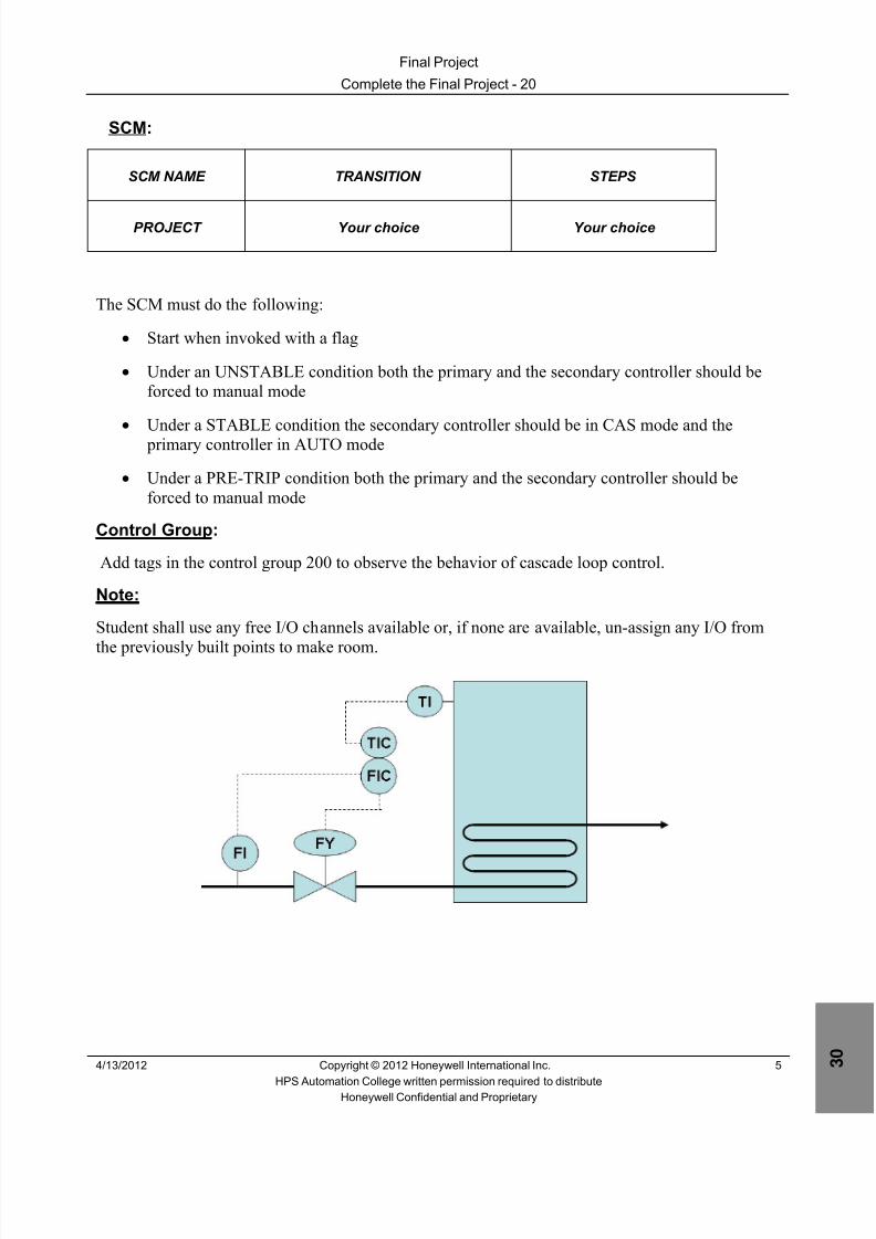
8/9/2019 Student Course Book- Automation
http://slidepdf.com/reader/full/student-course-book-automation 927/1165
Final Project
Complete the Final Project - 20
4/13/2012 Copyright © 2012 Honeywell International Inc. 5
HPS Automation College written permission required to distributeHoneywell Confidential and Proprietary
SCM:
SCM NAME TRANSITION STEPS
PROJECT Your choice Your choice
The SCM must do the following:
• Start when invoked with a flag
• Under an UNSTABLE condition both the primary and the secondary controller should beforced to manual mode
• Under a STABLE condition the secondary controller should be in CAS mode and the primary controller in AUTO mode
• Under a PRE-TRIP condition both the primary and the secondary controller should beforced to manual mode
Control Group:
Add tags in the control group 200 to observe the behavior of cascade loop control.
Note:
Student shall use any free I/O channels available or, if none are available, un-assign any I/O from
the previously built points to make room.

8/9/2019 Student Course Book- Automation
http://slidepdf.com/reader/full/student-course-book-automation 928/1165
Final Project
Complete the Final Project - 20
6 Copyright © 2012 Honeywell International Inc. 4/13/2012
HPS Automation College written permission required to distributeHoneywell Confidential and Proprietary
This page was intentionally left blank.

8/9/2019 Student Course Book- Automation
http://slidepdf.com/reader/full/student-course-book-automation 929/1165
1
1
Honeywell ConfidentialCopyright © 2012 Honeywell International Inc.
4/13/2012
Identify PMIO Hardware
PMIO Identify PMIO HardwarePMIO Identify PMIO Hardware
Honeywell
Honeywell ConfidentialCopyright © 2012 Honeywell International Inc.
4/13/20122
Introduction
• This lesson introduces you to the layout of atypical PMIO cabinet and its main components.
• At the conclusion of this lesson, you will beable to:
– Describe the layout of a typical PMIO cabinet
– Describe the PMIO power subsystem chassisand components
PMIO Identify PMIO Hardware

8/9/2019 Student Course Book- Automation
http://slidepdf.com/reader/full/student-course-book-automation 930/1165
2
Honeywell
Honeywell ConfidentialCopyright © 2012 Honeywell International Inc.
4/13/20123
Topics
• PMIO Cabinet Components
• PMIO Power Subsystem
PMIO Identify PMIO Hardware
Honeywell
Honeywell ConfidentialCopyright © 2012 Honeywell International Inc.
4/13/20124
Cabinet Layout
• Three Main Components
– I/O Processor Card Files
– C200/C200E Controller
– Power Subsystem
PMIO Identify PMIO Hardware
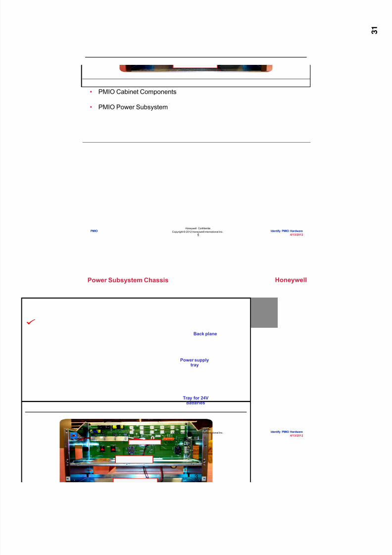
8/9/2019 Student Course Book- Automation
http://slidepdf.com/reader/full/student-course-book-automation 931/1165
3
Honeywell
Honeywell ConfidentialCopyright © 2012 Honeywell International Inc.
4/13/20125
Topics
• PMIO Cabinet Components
• PMIO Power Subsystem
PMIO Identify PMIO Hardware
Honeywell
Honeywell ConfidentialCopyright © 2012 Honeywell International Inc.
4/13/20126
Power Subsystem Chassis
Tray for 24Vbatteries
Power supplytray
Back plane
PMIO Identify PMIO Hardware
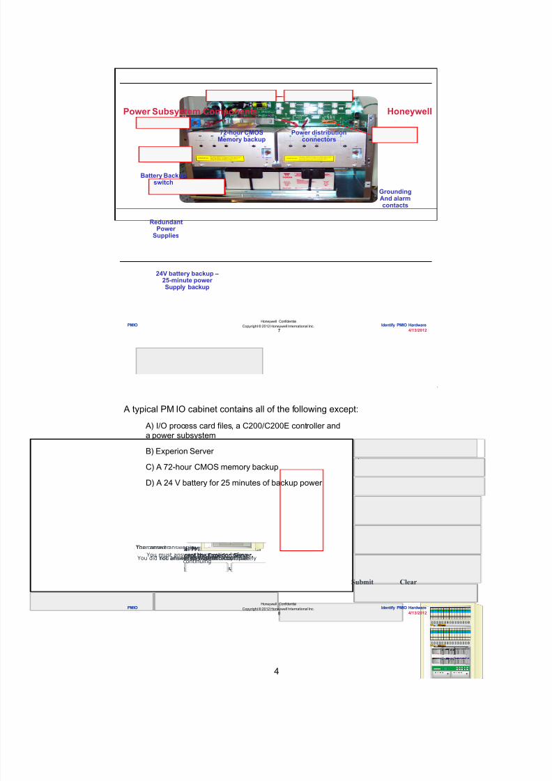
8/9/2019 Student Course Book- Automation
http://slidepdf.com/reader/full/student-course-book-automation 932/1165
4
Honeywell
Honeywell ConfidentialCopyright © 2012 Honeywell International Inc.
4/13/20127
Power Subsystem Components
GroundingAnd alarmcontacts
24V battery backup –25-minute powerSupply backup
RedundantPower
Supplies
72-hour CMOSMemory backup
Battery Backupswitch
Power distributionconnectors
PMIO Identify PMIO Hardware
Honeywell
Honeywell ConfidentialCopyright © 2012 Honeywell International Inc.
4/13/20128
Question 1: PMIO Cabinet Layout and Power Subsystem
Incorrect. A typical PM IO cabinet will containall of these except the Experion Server.
Click anywhere to continue.
Correct! A typical PM IO cabinet will containall of these except the Experion Server.
Click anywhere to continue.
Incorrect. A typical PM IO cabinet will containall of these except the Experion Server.
Click anywhere to continue.
Incorrect. A typical PM IO cabinet will containall of these except the Experion Server.
Click anywhere to continue.
Correct - Click anywhere to continueIncorrect - Click anywhere to continueYou answered this correctly! Your answer: The correct answer is:
You did not answer this question completelyYou must answer the question beforecontinuing
Submit Clear
A typical PM IO cabinet contains all of the following except: A) I/O process card files, a C200/C200E controller anda power subsystem
B) Experion Server
C) A 72-hour CMOS memory backup
D) A 24 V battery for 25 minutes of backup power
PMIO Identify PMIO Hardware

8/9/2019 Student Course Book- Automation
http://slidepdf.com/reader/full/student-course-book-automation 933/1165
5
Honeywell
Honeywell ConfidentialCopyright © 2012 Honeywell International Inc.
4/13/20129
• A typical PMIO cabinet has 3 sections. Top to bottom they are:
– I/O processor cards
– A C200/C200E controller
– A power subsystem
• The power subsystem can have:
– Redundant power supplies
– Full power battery backup
– CMOS battery backup for databases on the PMIO cards
Summary
PMIO Identify PMIO Hardware
Honeywell
Honeywell ConfidentialCopyright © 2012 Honeywell International Inc.
4/13/201210
Conclusion
Identify PMIO Hardware
CompletionCertificate
Proceed to the next lesson in your course material
PMIO Identify PMIO Hardware

8/9/2019 Student Course Book- Automation
http://slidepdf.com/reader/full/student-course-book-automation 934/1165
6
11
Honeywell ConfidentialCopyright © 2012 Honeywell International Inc.
4/13/2012
Describe the C200/C200E Hardware Interfaceto the PMIO
PMIO Describe the C200/C200E Hardware Interface to the PMIOPMIO Describe the C200/C200E Hardware Interface to the PMIO
Honeywell
Honeywell ConfidentialCopyright © 2012 Honeywell International Inc.
4/13/201212
Introduction
• In this lesson, you will learn about theC200/C200Eand PMIO interface componentscontained in the C200/C200E rack.
• At the conclusion of this lesson, you will beable to:
– Describe the I/O link interface module (IOLIM)
– Identify the I/O link (IOL) interface cable andconnections
PMIO Describe the C200/C200E Hardware Interface to the PMIO
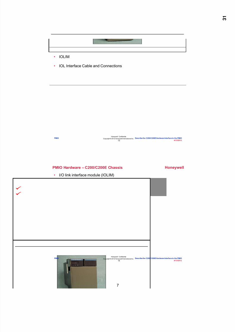
8/9/2019 Student Course Book- Automation
http://slidepdf.com/reader/full/student-course-book-automation 935/1165
7
Honeywell
Honeywell ConfidentialCopyright © 2012 Honeywell International Inc.
4/13/201213
• IOLIM
• IOL Interface Cable and Connections
Topics
PMIO Describe the C200/C200E Hardware Interface to the PMIO
Honeywell
Honeywell ConfidentialCopyright © 2012 Honeywell International Inc.
4/13/201214
PMIO Hardware – C200/C200E Chassis
• I/O link interface module (IOLIM)
PMIO Describe the C200/C200E Hardware Interface to the PMIO
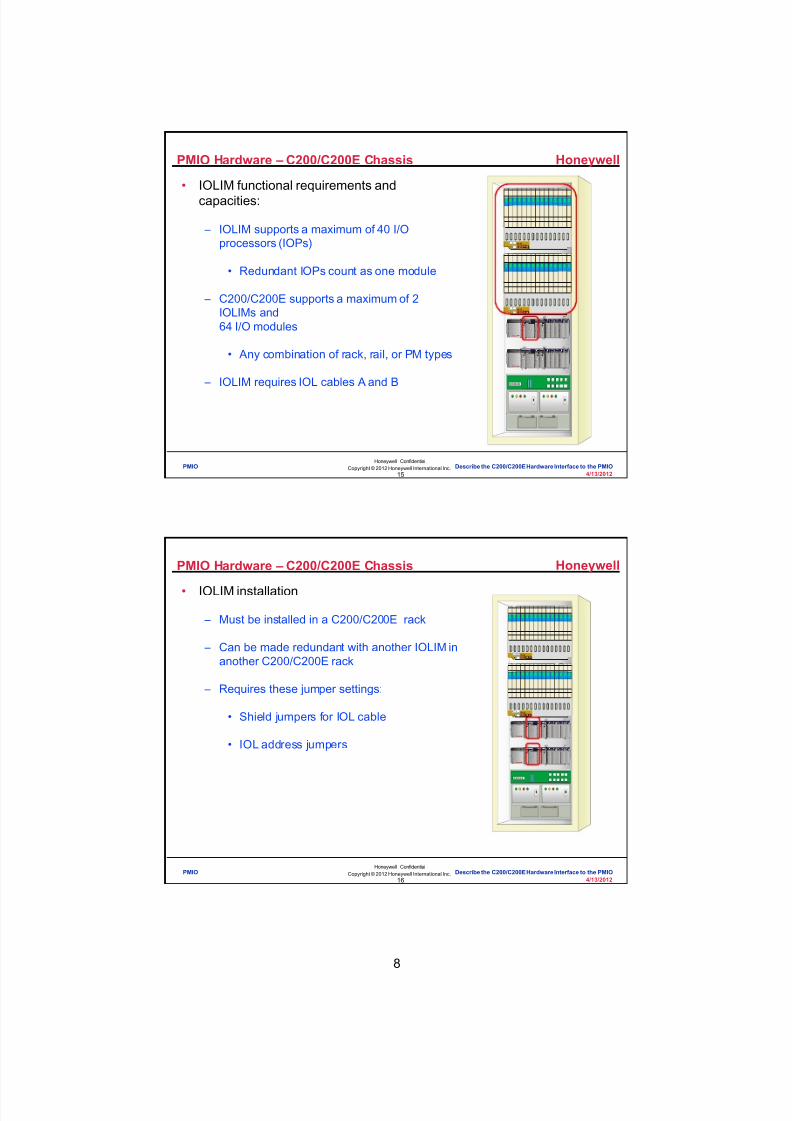
8/9/2019 Student Course Book- Automation
http://slidepdf.com/reader/full/student-course-book-automation 936/1165
8
Honeywell
Honeywell ConfidentialCopyright © 2012 Honeywell International Inc.
4/13/201215
PMIO Hardware – C200/C200E Chassis
• IOLIM functional requirements andcapacities:
– IOLIM supports a maximum of 40 I/Oprocessors (IOPs)
• Redundant IOPs count as one module
– C200/C200E supports a maximum of 2IOLIMs and64 I/O modules
• Any combination of rack, rail, or PM types
– IOLIM requires IOL cables A and B
PMIO Describe the C200/C200E Hardware Interface to the PMIO
Honeywell
Honeywell ConfidentialCopyright © 2012 Honeywell International Inc.
4/13/201216
PMIO Hardware – C200/C200E Chassis
• IOLIM installation
– Must be installed in a C200/C200E rack
– Can be made redundant with another IOLIM inanother C200/C200E rack
– Requires these jumper settings:
• Shield jumpers for IOL cable
• IOL address jumpers
PMIO Describe the C200/C200E Hardware Interface to the PMIO
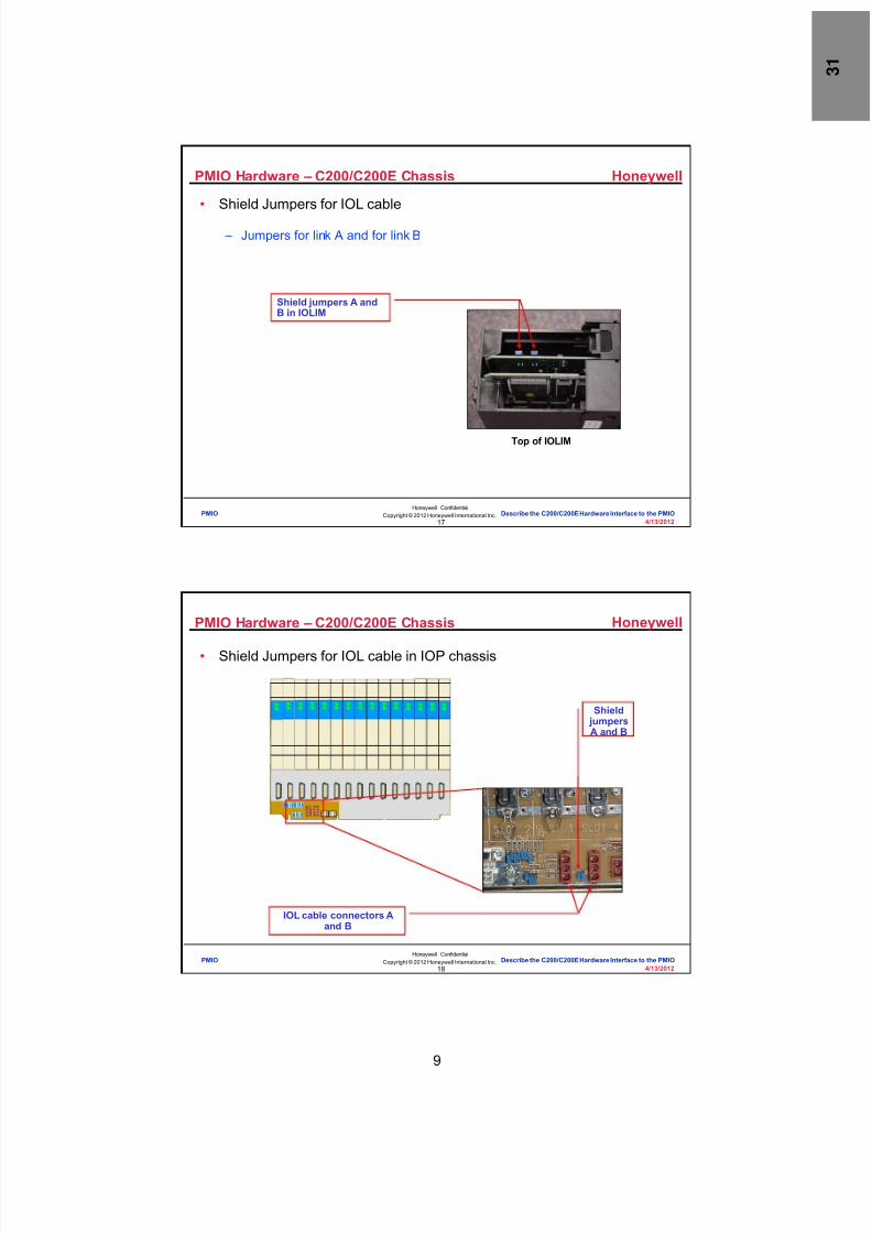
8/9/2019 Student Course Book- Automation
http://slidepdf.com/reader/full/student-course-book-automation 937/1165
9
Honeywell
Honeywell ConfidentialCopyright © 2012 Honeywell International Inc.
4/13/201217
PMIO Hardware – C200/C200E Chassis
• Shield Jumpers for IOL cable
– Jumpers for link A and for link B
Top of IOLIM
Shield jumpers A andB in IOLIM
PMIO Describe the C200/C200E Hardware Interface to the PMIO
Honeywell
Honeywell ConfidentialCopyright © 2012 Honeywell International Inc.
4/13/201218
PMIO Hardware – C200/C200E Chassis
• Shield Jumpers for IOL cable in IOP chassis
Shield jumpersA and B
IOL cable connectors Aand B
PMIO Describe the C200/C200E Hardware Interface to the PMIO

8/9/2019 Student Course Book- Automation
http://slidepdf.com/reader/full/student-course-book-automation 938/1165
10
Honeywell
Honeywell ConfidentialCopyright © 2012 Honeywell International Inc.
4/13/201219
Bottom of IOLIM
PMIO Hardware – C200/C200E Chassis
• IOL address jumper
– Only important when IOLIM is redundant
– Redundant partner must be different (one in, one out)
– Doesn’t matter which is which
– If not redundant, can be in or out
IOL address jumper
PMIO Describe the C200/C200E Hardware Interface to the PMIO
Honeywell
Honeywell ConfidentialCopyright © 2012 Honeywell International Inc.
4/13/201220
Question 1: IOPs
Incorrect. Each IOLIM can support 40 IOPs.
Click anywhere to continue.
Incorrect. Each IOLIM can support 40 IOPs.
Click anywhere to continue.
Correct! Each IOLIM can support 40 IOPs.
Click anywhere to continue.
Incorrect. Each IOLIM can support 40 IOPs.
Click anywhere to continue.Correct - Click anywhere to continueIncorrect - Click anywhere to continueYou answered this correctly!
Your answer: The correct answer is:
You did not answer this question completelyYou must answer the question beforecontinuing
Submit Clear
How many IOPs can an IOLIM support? A) 2
B) 10
C) 40
D) 64
PMIO Describe the C200/C200E Hardware Interface to the PMIO

8/9/2019 Student Course Book- Automation
http://slidepdf.com/reader/full/student-course-book-automation 939/1165
11
Honeywell
Honeywell ConfidentialCopyright © 2012 Honeywell International Inc.
4/13/201221
Question 2: Redundant IOLIMs
Correct! For redundant IOLIMs the link address jumpermust be set in one of the two IOLIMs. It does not matter
which of IOLIM has the jumper set.
Click anywhere to continue.
Incorrect. For redundant IOLIMs the link address jumpermust be set in one of the two IOLIMs. It does not matter
which of IOLIM has the jumper set.
Click anywhere to continue.
Incorrect. For redundant IOLIMs the link address jumpermust be set in one of the two IOLIMs. It does not matter
which of IOLIM has the jumper set.
Click anywhere to continue.
Incorrect. For redundant IOLIMs the link address jumpermust be set in one of the two IOLIMs. It does not matter
which of IOLIM has the jumper set.
Click anywhere to continue.
Correct - Click anywhere to continueIncorrect - Click anywhere to continueYou answered this correctly!
Your answer:The correct answer is:
You did not answer this question completelyYou must answer the question before
continuing
Submit Clear
For redundant IOLIMs, the link address jumper must be set in:
Bottom of IOLIM
A) One of the two IOLIMs (doesn't matter which one)
B) Both IOLIMs
C) The power subsystem compartment
D) None of the above
PMIO Describe the C200/C200E Hardware Interface to the PMIO
Honeywell
Honeywell ConfidentialCopyright © 2012 Honeywell International Inc.
4/13/201222
Topics
• IOLIM
• IOL Interface Cable and Connections
PMIO Describe the C200/C200E Hardware Interface to the PMIO

8/9/2019 Student Course Book- Automation
http://slidepdf.com/reader/full/student-course-book-automation 940/1165
12
Honeywell
Honeywell ConfidentialCopyright © 2012 Honeywell International Inc.
4/13/201223
PMIO Hardware – C200/C200E Chassis
• IOL interface cable layout
To IO linkCable A
To cabinet powerSubsystem output
connector
To C200/C200Erack 24VDC
power supply
To IOLIMRJ-45
Connector B
To IOLIMRJ-45
Connector A
Power cableLength: 2, 5 and 10
meters
IOL interfacecable Length: 2,5 and 10 meters
To IO linkCable B
PMIO Describe the C200/C200E Hardware Interface to the PMIO
Honeywell
Honeywell ConfidentialCopyright © 2012 Honeywell International Inc.
4/13/201224
PMIO Hardware – C200/C200E Chassis
• IOL interface cable
– Connection at IOLIM
PMIO Describe the C200/C200E Hardware Interface to the PMIO

8/9/2019 Student Course Book- Automation
http://slidepdf.com/reader/full/student-course-book-automation 941/1165
13
Honeywell
Honeywell ConfidentialCopyright © 2012 Honeywell International Inc.
4/13/201225
PMIO Hardware – C200/C200E Chassis
• IOL interface cable
Power distribution panelconnection
PMIO Describe the C200/C200E Hardware Interface to the PMIO
Honeywell
Honeywell ConfidentialCopyright © 2012 Honeywell International Inc.
4/13/201226
PMIO Hardware – C200/C200E Chassis
• 24VDC Power Supply
PMIO Describe the C200/C200E Hardware Interface to the PMIO

8/9/2019 Student Course Book- Automation
http://slidepdf.com/reader/full/student-course-book-automation 942/1165
14
Honeywell
Honeywell ConfidentialCopyright © 2012 Honeywell International Inc.
4/13/201227
Question 3: IOL Interface Cable and Connections
Incorrect. The IOL interface cable does not connect to the"IOLIM power subsystem". There is no IOLIM power
subsystem. The IOL interface cable connects to the cabinetpower subsystem.
Click anywhere to continue.
Incorrect. The IOL interface cable does not connect to the"IOLIM power subsystem". There is no IOLIM power
subsystem. The IOL interface cable connects to the cabinetpower subsystem.
Click anywhere to continue.
Incorrect. The IOL interface cable does not connect to the"IOLIM power subsystem". There is no IOLIM power
subsystem. The IOL interface cable connects to the cabinetpower subsystem.
Click anywhere to continue.
Correct! The IOL interface cable does not connect to the"IOLIM power subsystem". There is no IOLIM power
subsystem. The IOL interface cable connects to the cabinetpower subsystem.
Click anywhere to continue.
Correct - Click anywhere to continueIncorrect - Click anywhere to continueYou answered this correctly!
Your answer:The correct answer is:
You did not answer this question completelyYou must answer the question beforecontinuing
Submit Clear
The IOL interface cables connect to all of these except:
A) IOLIM RJ-45 connectors A and B
B) IOL cables A and B
C) C200/C200E rack 24VDC power supply
D) IOLIM power subsystem
PMIO Describe the C200/C200E Hardware Interface to the PMIO
Honeywell
Honeywell ConfidentialCopyright © 2012 Honeywell International Inc.
4/13/201228
Summary
• The hardware required to interface the C200/C200E to the PMIOincludes the IOLIM and IOL cables. – A C200/C200E supports up to 2 IOLIMs and 64 I/O modules
– An IOLIM supports up to 40 redundant IOPs.
– Shield jumpers for IO Link Cables A and B are located on both the IOLIMand the PMIO backplane.
– For redundant IOLIMs, the link address jumper must be set in one of the twoIOLIMs (doesn't matter which one).
– The IOL cable connects to:• IOLIM RJ-45 connectors A and B
• IOL cables A and B• C200/C200E rack 24VDC power supply• Cabinet power subsystem
PMIO Describe the C200/C200E Hardware Interface to the PMIO

8/9/2019 Student Course Book- Automation
http://slidepdf.com/reader/full/student-course-book-automation 943/1165
15
Honeywell
Honeywell ConfidentialCopyright © 2012 Honeywell International Inc.
4/13/201229
Conclusion
Describe the C200/C200E Hardware Interface to the PMIO
CompletionCertificate
Proceed to the next lesson in your course material
PMIO Describe the C200/C200E Hardware Interface to the PMIO
Honeywell
Honeywell ConfidentialCopyright © 2012 Honeywell International Inc.
4/13/201230
This page intentionally left blank
PMIO Describe the C200/C200E Hardware Interface to the PMIO

8/9/2019 Student Course Book- Automation
http://slidepdf.com/reader/full/student-course-book-automation 944/1165
16
31
Honeywell ConfidentialCopyright © 2012 Honeywell International Inc.
4/13/2012
Describe the I/O Card File
PMIO Describe the I/O Card FilePMIO Describe the I/O Card File
Honeywell
Honeywell ConfidentialCopyright © 2012 Honeywell International Inc.
4/13/201232
Introduction
• In this lesson you will learn about thecomponents of the I/O processor card filefound in the PMIO cabinet.
• At the conclusion of this lesson, you will beable to:
– Identify the I/O link (IOL) interface cableconnections
– Locate an I/O processor (IOP) in a card file
– Explain card file addressing
– Identify the power connections
PMIO Describe the I/O Card File

8/9/2019 Student Course Book- Automation
http://slidepdf.com/reader/full/student-course-book-automation 945/1165
17
Honeywell
Honeywell ConfidentialCopyright © 2012 Honeywell International Inc.
4/13/201233
Topics
• IOL Connections
• IOP Location
• Card File Addressing
• Power Connections
PMIO Describe the I/O Card File
Honeywell
Honeywell ConfidentialCopyright © 2012 Honeywell International Inc.
4/13/201234
Cards 1 - 15
Cards 1 - 15 C N IServer
PCIC
24
01
C 2 0 0
I O L I M
IOL cables
File 5
File 4
Cards 1 - 15
File 3
IOL Interface Cable Connections – PMIO
PMIO Describe the I/O Card File

8/9/2019 Student Course Book- Automation
http://slidepdf.com/reader/full/student-course-book-automation 946/1165

8/9/2019 Student Course Book- Automation
http://slidepdf.com/reader/full/student-course-book-automation 947/1165
19
Honeywell
Honeywell ConfidentialCopyright © 2012 Honeywell International Inc.
4/13/201237
Cards 1 - 15
Cards 1 - 15 C N IServer
PCIC
24
01
C 2 0 0
I O L I M
IOL cables
File 5
File 4
Cards 1 - 15
File 3
IOP Card File Locations – PMIO
PMIO Describe the I/O Card File
Honeywell
Honeywell ConfidentialCopyright © 2012 Honeywell International Inc.
4/13/201238
IOP Locations – PMIO
• Card file with cover plate
– IOP cards are referenced by their numerical location within each card file.
1 2 3 4 5 6 7 8 9 10 11 12 13 14 15
PMIO Describe the I/O Card File
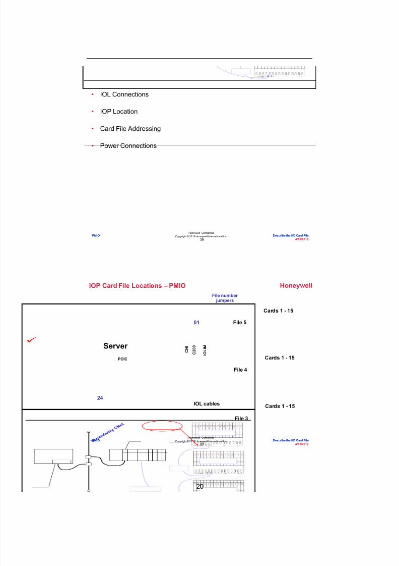
8/9/2019 Student Course Book- Automation
http://slidepdf.com/reader/full/student-course-book-automation 948/1165
20
Honeywell
Honeywell ConfidentialCopyright © 2012 Honeywell International Inc.
4/13/201239
Topics
• IOL Connections
• IOP Location
• Card File Addressing
• Power Connections
PMIO Describe the I/O Card File
Honeywell
Honeywell ConfidentialCopyright © 2012 Honeywell International Inc.
4/13/201240
Cards 1 - 15
Cards 1 - 15 C N IServer
PCIC
24
01
C 2 0 0
I O L I M
IOL cables
File 5
File 4
Cards 1 - 15
File 3
IOP Card File Locations – PMIO
File number jumpers
PMIO Describe the I/O Card File

8/9/2019 Student Course Book- Automation
http://slidepdf.com/reader/full/student-course-book-automation 949/1165
21
Honeywell
Honeywell ConfidentialCopyright © 2012 Honeywell International Inc.
4/13/201241
File Number Jumpers for IOP Chassis
• File numbers range from 1 to 8
File number jumpers
PMIO Describe the I/O Card File
Honeywell
Honeywell ConfidentialCopyright © 2012 Honeywell International Inc.
4/13/201242
File Number Jumpers for IOP Chassis
• Pin setting is one less than actual file number
• Odd parity
P 4 2 1FILE ADDR
File # 3Pinned 2
P 4 2 1FILE ADDR
File # 8Pinned 7
P 4 2 1FILE ADDR
File # 4Pinned 3
PMIO Describe the I/O Card File

8/9/2019 Student Course Book- Automation
http://slidepdf.com/reader/full/student-course-book-automation 950/1165
22
Honeywell
Honeywell ConfidentialCopyright © 2012 Honeywell International Inc.
4/13/201243
UCN Address Jumpers
• UCN address jumpers do not apply to Experion PKS
UCN address jumpers – donot set these (remove)
PMIO Describe the I/O Card File
Honeywell
Honeywell ConfidentialCopyright © 2012 Honeywell International Inc.
4/13/201244
When setting address jumpers for card file #6 whichpins must have jumpers?
Question 1: File Addressing
Incorrect. For card file #6, pins, 4, 1 and P must have jumpers.Since we are pinning out card file #6 we actually pin it as #5
therefore we pin 4 and 1. When we do this we have an evennumber of jumpers set which goes against the odd parity rule.This rule states that at all times an odd number of jumpers must
be set. Therefore we must set the 'P' parity jumper.
Click anywhere to continue.
Correct - Click anywhere to continueIncorrect - Click anywhere to continueYou answered this correctly!
Your answer:The correct answer is:
You did not answer this question completelyYou must answer the question beforecontinuing
Submit Clear
Correct! For card file #6, pins, 4, 1 and P must have jumpers.Since we are pinning out card file #6 we actually pin it as #5
therefore we pin 4 and 1. When we do this we have an evennumber of jumpers set which goes against the odd parity rule.This rule states that at all times an odd number of jumpers must
be set. Therefore we must set the 'P' parity jumper.
Click anywhere to continue.
Incorrect. For card file #6, pins, 4, 1 and P must have jumpers.Since we are pinning out card file #6 we actually pin it as #5
therefore we pin 4 and 1. When we do this we have an evennumber of jumpers set which goes against the odd parity rule.This rule states that at all times an odd number of jumpers must
be set. Therefore we must set the 'P' parity jumper.
Click anywhere to continue.
P 4 2 1
FILE ADDR
A) 4, 1
B) 4, 1, P
C) 4, 2
D) 4, 2, P
PMIO Describe the I/O Card File
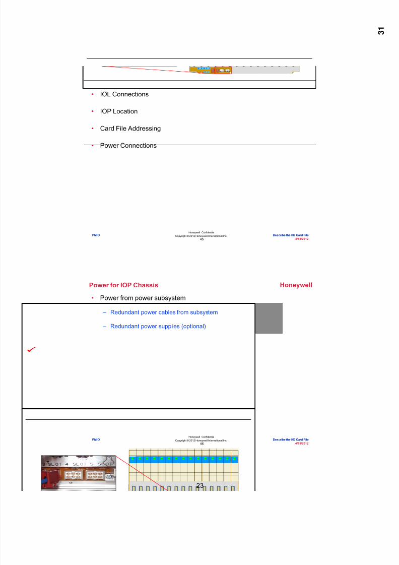
8/9/2019 Student Course Book- Automation
http://slidepdf.com/reader/full/student-course-book-automation 951/1165
23
Honeywell
Honeywell ConfidentialCopyright © 2012 Honeywell International Inc.
4/13/201245
Topics
• IOL Connections
• IOP Location
• Card File Addressing
• Power Connections
PMIO Describe the I/O Card File
Honeywell
Honeywell ConfidentialCopyright © 2012 Honeywell International Inc.
4/13/201246
Power for IOP Chassis
• Power from power subsystem
– Redundant power cables from subsystem
– Redundant power supplies (optional)
PMIO Describe the I/O Card File
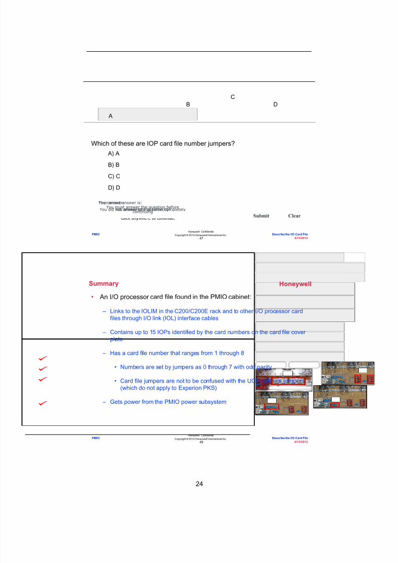
8/9/2019 Student Course Book- Automation
http://slidepdf.com/reader/full/student-course-book-automation 952/1165
24
Honeywell
Honeywell ConfidentialCopyright © 2012 Honeywell International Inc.
4/13/201247
Question 2: IOP Jumpers and Connections
Correct! Picture 'A' shows the IOP card filenumber jumpers.
Click anywhere to continue.
Incorrect! Picture 'A' shows the IOP card filenumber jumpers.
Click anywhere to continue.
Incorrect! Picture 'A' shows the IOP card filenumber jumpers.
Click anywhere to continue.
Incorrect! Picture 'A' shows the IOP card filenumber jumpers.
Click anywhere to continue.
Correct - Click anywhere to continueIncorrect - Click anywhere to continueYou answered this correctly!
Your answer:The correct answer is:
You did not answer this question completelyYou must answer the question beforecontinuing
Submit Clear
Which of these are IOP card file number jumpers?
C
A
B D
A) A
B) B
C) C
D) D
PMIO Describe the I/O Card File
Honeywell
Honeywell ConfidentialCopyright © 2012 Honeywell International Inc.
4/13/201248
• An I/O processor card file found in the PMIO cabinet:
– Links to the IOLIM in the C200/C200E rack and to other I/O processor cardfiles through I/O link (IOL) interface cables
– Contains up to 15 IOPs identified by the card numbers on the card file coverplate
– Has a card file number that ranges from 1 through 8
• Numbers are set by jumpers as 0 through 7 with odd parity
• Card file jumpers are not to be confused with the UCN address jumpers(which do not apply to Experion PKS)
– Gets power from the PMIO power subsystem
Summary
PMIO Describe the I/O Card File

8/9/2019 Student Course Book- Automation
http://slidepdf.com/reader/full/student-course-book-automation 953/1165
25
Honeywell
Honeywell ConfidentialCopyright © 2012 Honeywell International Inc.
4/13/201249
Conclusion
Describe the I/O Card File
CompletionCertificate
Proceed to the next lesson in your course material.
PMIO Describe the I/O Card File
Honeywell
Honeywell ConfidentialCopyright © 2012 Honeywell International Inc.
4/13/201250
This page intentionally left blank
PMIO Describe the I/O Card File

8/9/2019 Student Course Book- Automation
http://slidepdf.com/reader/full/student-course-book-automation 954/1165
26
51
Honeywell ConfidentialCopyright © 2012 Honeywell International Inc.
4/13/2012
Describe How to Configure PMIO Hardware
PMIO Describe How to Configure PMIO HardwarePMIO Describe How to Configure PMIO Hardware
Honeywell
Honeywell ConfidentialCopyright © 2012 Honeywell International Inc.
4/13/201252
Introduction
• In this lesson you will learn how to configure PMIO hardware in ControlBuilder.
• At the conclusion of this lesson, you will know how to:
– Configure an I/O link interface module (IOLIM)
– Add I/O processor (IOP) modules to the I/O link (IOL)
– Load and activate IOPs
PMIO Describe How to Configure PMIO Hardware

8/9/2019 Student Course Book- Automation
http://slidepdf.com/reader/full/student-course-book-automation 955/1165
27
Honeywell
Honeywell ConfidentialCopyright © 2012 Honeywell International Inc.
4/13/201253
Topics
• Configuring an IOLIM
• Adding IOPs to the IOL
• Loading and Activating IOPs
PMIO Describe How to Configure PMIO Hardware
Honeywell
Honeywell ConfidentialCopyright © 2012 Honeywell International Inc.
4/13/201254
Configure an IOLIM
• Select IOLIM from the list of interface modules
– An IOLIM appears in the Project tab and
– A configuration dialog box opens (next slide)
PMIO Describe How to Configure PMIO Hardware

8/9/2019 Student Course Book- Automation
http://slidepdf.com/reader/full/student-course-book-automation 956/1165
28
Honeywell
Honeywell ConfidentialCopyright © 2012 Honeywell International Inc.
4/13/201255
Configure an IOLIM
• Enter configuration parameters and click OK
SupervisoryCNI module
IOLIM slotnumber
Check ifIOLIM isredundant
Fill in secondaryIOLIM name ifredundant
PMIO Describe How to Configure PMIO Hardware
Honeywell
Honeywell ConfidentialCopyright © 2012 Honeywell International Inc.
4/13/201256
Configure an IOLIM
• Double-click the IOL under the IOLIM in Project
• Enter a name and description
PMIO Describe How to Configure PMIO Hardware

8/9/2019 Student Course Book- Automation
http://slidepdf.com/reader/full/student-course-book-automation 957/1165
29
Honeywell
Honeywell ConfidentialCopyright © 2012 Honeywell International Inc.
4/13/201257
Question 1: Configuring an IOLIM
Correct - Click anywhere to continueIncorrect - Click anywhere to continueYou answered this correctly!
Your answer:The correct answer is:
You did not answer this question completelyYou must answer the question beforecontinuing
Submit Clear
No. When you configure an IOLIM, you mustcomplete all of these steps except "Create a new
IOL for the IOLIM and enter its name anddescription". When an IOLIM is added the IOL is
automatically created by Control Builder.
Click anywhere to continue.
No. When you configure an IOLIM, you mustcomplete all of these steps except "Create a new
IOL for the IOLIM and enter its name anddescription". When an IOLIM is added the IOL is
automatically created by Control Builder.
Click anywhere to continue.
Yes! When you configure an IOLIM, you mustcomplete all of these steps except "Create a new
IOL for the IOLIM and enter its name anddescription". When an IOLIM is added the IOL is
automatically created by Control Builder.
Click anywhere to continue.
No. When you configure an IOLIM, you mustcomplete all of these steps except "Create a new
IOL for the IOLIM and enter its name anddescription". When an IOLIM is added the IOL is
automatically created by Control Builder.
Click anywhere to continue.
When you configure an IOLIM, you must complete all of these steps except:
A) Create the IOLIM in Control Builder
B) Enter IOLIM configuration parameters including theC200/C200E chassis slot number in which it resides
C) Create a new IOL for the IOLIM and enter its nameand description
D) Enter the name and description for the IOL that iscreated automatically when you create the IOLIM
PMIO Describe How to Configure PMIO Hardware
Honeywell
Honeywell ConfidentialCopyright © 2012 Honeywell International Inc.
4/13/201258
Topics
• Configuring an IOLIM
• Adding IOPs to the IOL
• Loading and Activating IOPs
PMIO Describe How to Configure PMIO Hardware

8/9/2019 Student Course Book- Automation
http://slidepdf.com/reader/full/student-course-book-automation 958/1165

8/9/2019 Student Course Book- Automation
http://slidepdf.com/reader/full/student-course-book-automation 959/1165

8/9/2019 Student Course Book- Automation
http://slidepdf.com/reader/full/student-course-book-automation 960/1165
32
Honeywell
Honeywell ConfidentialCopyright © 2012 Honeywell International Inc.
4/13/201263
Question 2: IOP Assignment
Correct - Click anywhere to continueIncorrect - Click anywhere to continueYou answered this correctly!
Your answer:The correct answer is:
You did not answer this question completelyYou must answer the question before
continuing
Submit Clear
Incorrect. IOPs are assigned to an IOL.
Click anywhere to continue.
Incorrect. IOPs are assigned to an IOL.
Click anywhere to continue.
Correct! IOPs are assigned to an IOL.
Click anywhere to continue.
Incorrect. IOPs are assigned to an IOL.
Click anywhere to continue.
IOPs are assigned to:
A) A control execution environment (CEE)
B) An IOLIM
C) An IOL
D) Nothing. IOPs remain unassigned
PMIO Describe How to Configure PMIO Hardware
Honeywell
Honeywell ConfidentialCopyright © 2012 Honeywell International Inc.
4/13/201264
Topics
• Configuring an IOLIM
• Adding IOPs to the IOL
• Loading and Activating IOPs
PMIO Describe How to Configure PMIO Hardware

8/9/2019 Student Course Book- Automation
http://slidepdf.com/reader/full/student-course-book-automation 961/1165
33
Honeywell
Honeywell ConfidentialCopyright © 2012 Honeywell International Inc.
4/13/201265
Loading IOLIM, IOL, and IOPs
• Right click the IOLIM
– Select Load with Contents
PMIO Describe How to Configure PMIO Hardware
Honeywell
Honeywell ConfidentialCopyright © 2012 Honeywell International Inc.
4/13/201266
Loading IOLIM, IOL, and IOPs
• Verify the load list
• Do not check
PMIO Describe How to Configure PMIO Hardware

8/9/2019 Student Course Book- Automation
http://slidepdf.com/reader/full/student-course-book-automation 962/1165
34
Honeywell
Honeywell ConfidentialCopyright © 2012 Honeywell International Inc.
4/13/201267
Loading IOLIM, IOL, and IOPs
• After successful load, Monitor tab displays IOPs in blue.
– Indicates IOP is inactive
PMIO Describe How to Configure PMIO Hardware
Honeywell
Honeywell ConfidentialCopyright © 2012 Honeywell International Inc.
4/13/201268
Loading IOLIM, IOL, and IOPs
• In Project, IOP channels appear under theIOP.
• In Monitoring, IOP channels appear underthe IOP only after the CM that uses thechannel is downloaded.
PMIO Describe How to Configure PMIO Hardware

8/9/2019 Student Course Book- Automation
http://slidepdf.com/reader/full/student-course-book-automation 963/1165
35
Honeywell
Honeywell ConfidentialCopyright © 2012 Honeywell International Inc.
4/13/201269
Loading IOLIM, IOL, and IOPs
• When valid, LED turns green.
– IOP changes from yellow to blue in Monitor tree
• IOP can be activated from the monitoring tree or from a combo box.
– (Run = Active)
PMIO Describe How to Configure PMIO Hardware
Honeywell
Honeywell ConfidentialCopyright © 2012 Honeywell International Inc.
4/13/201270
Question 3: Loading and Activating IOPs
Correct - Click anywhere to continueIncorrect - Click anywhere to continueYou answered this correctly!Your answer:The correct answer is:You did not answer this question completelyYou must answer the question before
continuing
Submit Clear
Incorrect. The false statement is " The Project tab
displays IOPs in blue when they are loaded." Actuallythe Monitor tab displays the IOPS in blue. T he Project
tab will not display colors next to the IOPS.
Click anywhere to continue.
Correct! The false statement is " The Project tab
displays IOPs in blue when they are loaded." Actuallythe Monitor tab displays the IOPS in blue. T he Project
tab will not display colors next to the IOPS.
Click anywhere to continue.
Incorrect. The false statement is " The Project tab
displays IOPs in blue when they are loaded." Actuallythe Monitor tab displays the IOPS in blue. T he Project
tab will not display colors next to the IOPS.
Click anywhere to continue.
Incorrect. The false statement is " The Project tab
displays IOPs in blue when they are loaded." Actuallythe Monitor tab displays the IOPS in blue. T he Project
tab will not display colors next to the IOPS.
Click anywhere to continue.
Which statement about loading and activating IOPs is false?
A) The IOL is automatically loaded with its IOLIM
B) The Project tab displays IOPs in blue whenthey are located successfully
C) IOP channels appear under the IOP in theProject tab
D) An IOP can be activated by changing itsexecution state to Run
PMIO Describe How to Configure PMIO Hardware

8/9/2019 Student Course Book- Automation
http://slidepdf.com/reader/full/student-course-book-automation 964/1165
36
Honeywell
Honeywell ConfidentialCopyright © 2012 Honeywell International Inc.
4/13/201271
Summary
• When you configure an IOLIM and its associated hardware, remember:
– Create and configure the IOLIM in Control Builder
– The IOL is created automatically when you create the IOLIM
– Assign IOPs to the IOL and not the IOLIM
– The Monitor tab displays IOPs in blue when they are loaded successfully
PMIO Describe How to Configure PMIO Hardware
Honeywell
Honeywell ConfidentialCopyright © 2012 Honeywell International Inc.
4/13/201272
Conclusion
Describe How to Configure PMIO Hardware
CompletionCertificate
Proceed to the next lesson in your course material.
PMIO Describe How to Configure PMIO Hardware

8/9/2019 Student Course Book- Automation
http://slidepdf.com/reader/full/student-course-book-automation 965/1165
37
73
Honeywell ConfidentialCopyright © 2012 Honeywell International Inc.
4/13/2012
Describe How to Configure PMIO ChannelBlocks in CMs
PMIO Describe How to Configure PMIO Channel Blocks in CMsPMIO Describe How to Configure PMIO Channel Blocks in CMs
Honeywell
Honeywell ConfidentialCopyright © 2012 Honeywell International Inc.
4/13/201274
Introduction
• In this lesson you will learn to configure a PMIO channel block in acontrol module (CM).
• At the conclusion of this lesson, you will know how to:
– Configure and load a PMIO channel block
– Activate and delete a PMIO channel block
PMIO Describe How to Configure PMIO Channel Blocks in CMs

8/9/2019 Student Course Book- Automation
http://slidepdf.com/reader/full/student-course-book-automation 966/1165
38
Honeywell
Honeywell ConfidentialCopyright © 2012 Honeywell International Inc.
4/13/201275
Topics
• Configuring and Loading a PMIO Channel Block
• Activating and Deleting a PMIO Channel Block
PMIO Describe How to Configure PMIO Channel Blocks in CMs
Honeywell
Honeywell ConfidentialCopyright © 2012 Honeywell International Inc.
4/13/201276
Adding and Assigning a Channel Block
• First, add and assign a PMIO channel block; then, configure the blockparameters.
– Two methods to add and assign a PMIO channel block:
• Method 1: Add block from Library -- PMIO tree;then, assign to specific a IOP and a specific channel
• Method 2: Add block from Project – the specific IOP and specificchannel are automatically assigned
PMIO Describe How to Configure PMIO Channel Blocks in CMs

8/9/2019 Student Course Book- Automation
http://slidepdf.com/reader/full/student-course-book-automation 967/1165
39
Honeywell
Honeywell ConfidentialCopyright © 2012 Honeywell International Inc.
4/13/201277
Adding and Assigning a Channel Block
• Method 1: Library – PMIO tree
– Click and drag the channel block to a CM
PMIO Describe How to Configure PMIO Channel Blocks in CMs
Honeywell
Honeywell ConfidentialCopyright © 2012 Honeywell International Inc.
4/13/201278
Assigning a Channel Block
• Right click the block to assign
Right-click Select FunctionBlock Assign
PMIO Describe How to Configure PMIO Channel Blocks in CMs

8/9/2019 Student Course Book- Automation
http://slidepdf.com/reader/full/student-course-book-automation 968/1165
40
Honeywell
Honeywell ConfidentialCopyright © 2012 Honeywell International Inc.
4/13/201279
Assigning a Channel Block
• The Function Block Assignment dialog box appears.
Select a channel fromthe list of availableIOP channels
Click Assign
PMIO Describe How to Configure PMIO Channel Blocks in CMs
Honeywell
Honeywell ConfidentialCopyright © 2012 Honeywell International Inc.
4/13/201280
Verifying the Channel Block Assignment
• After assigning an IOP channel, verify the IOP name and channelnumber appear in the block.
IOP and channel
now assigned
PMIO Describe How to Configure PMIO Channel Blocks in CMs

8/9/2019 Student Course Book- Automation
http://slidepdf.com/reader/full/student-course-book-automation 969/1165
41
Honeywell
Honeywell ConfidentialCopyright © 2012 Honeywell International Inc.
4/13/201281
Adding and Assigning a Channel Block
• Method 2: Project
– Click and drag from the IOP in Project
IOP and channelassigned automatically
PMIO Describe How to Configure PMIO Channel Blocks in CMs
Honeywell
Honeywell ConfidentialCopyright © 2012 Honeywell International Inc.
4/13/201282
Channel Block Name
After assignment, the channel namebecomes:CM name.Function Block name
PMIO Describe How to Configure PMIO Channel Blocks in CMs
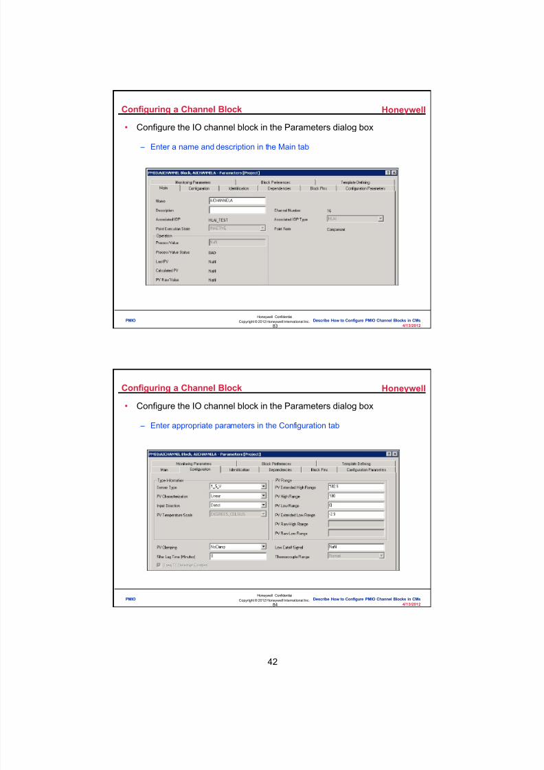
8/9/2019 Student Course Book- Automation
http://slidepdf.com/reader/full/student-course-book-automation 970/1165
42
Honeywell
Honeywell ConfidentialCopyright © 2012 Honeywell International Inc.
4/13/201283
Configuring a Channel Block
• Configure the IO channel block in the Parameters dialog box
– Enter a name and description in the Main tab
PMIO Describe How to Configure PMIO Channel Blocks in CMs
Honeywell
Honeywell ConfidentialCopyright © 2012 Honeywell International Inc.
4/13/201284
Configuring a Channel Block
• Configure the IO channel block in the Parameters dialog box
– Enter appropriate parameters in the Configuration tab
PMIO Describe How to Configure PMIO Channel Blocks in CMs

8/9/2019 Student Course Book- Automation
http://slidepdf.com/reader/full/student-course-book-automation 971/1165
43
Honeywell
Honeywell ConfidentialCopyright © 2012 Honeywell International Inc.
4/13/201285
Wiring and Downloading the Function Blocks
• Soft-wire the CM blocks
• Download
PMIO Describe How to Configure PMIO Channel Blocks in CMs
Honeywell
Honeywell ConfidentialCopyright © 2012 Honeywell International Inc.
4/13/201286
Downloading the CM
• In Monitoring, IOP channels appear underthe IOP after downloading the CM that usesthe channel
PMIO Describe How to Configure PMIO Channel Blocks in CMs

8/9/2019 Student Course Book- Automation
http://slidepdf.com/reader/full/student-course-book-automation 972/1165
44
Honeywell
Honeywell ConfidentialCopyright © 2012 Honeywell International Inc.
4/13/201287
Question 1: Loading a PMIO Channel Block
Incorrect. You must download a CM that uses achannel block to see the channel block in the
Monitoring tab. In, Monitoring, IOP channels appearunder the IOP only after the CM that uses the channel
is downloaded.
Click anywhere to continue.
Correct! You must download a CM that uses a channelblock to see the channel block in the Monitoring tab.In, Monitoring, IOP channels appear under the IOP
only after the CM that use s the channel is downloaded.
Click anywhere to continue.
Incorrect. You must download a CM that uses achannel block to see the channel block in the
Monitoring tab. In, Monitoring, IOP channels appearunder the IOP only after the CM that uses the channel
is downloaded.
Click anywhere to continue.
Incorrect. You must download a CM that uses achannel block to see the channel block in the
Monitoring tab. In, Monitoring, IOP channels appearunder the IOP only after the CM that uses the channel
is downloaded.
Click anywhere to continue.
Correct - Click anywhere to continueIncorrect - Click anywhere to continueYou answered this correctly!
Your answer:The correct answer is:
You did not answer this question completelyYou must answer the question before
continuing
Submit Clear
You must download a CM that uses a channel block to see the channel
block in which tab in the Control Builder:
A) Library tab
B) Monitoring tab
C) Project tab
D) All of the above
PMIO Describe How to Configure PMIO Channel Blocks in CMs
Honeywell
Honeywell ConfidentialCopyright © 2012 Honeywell International Inc.
4/13/201288
• Configuring and Loading a PMIO Channel Block
• Activating and Deleting a PMIO Channel Block
Topics
PMIO Describe How to Configure PMIO Channel Blocks in CMs
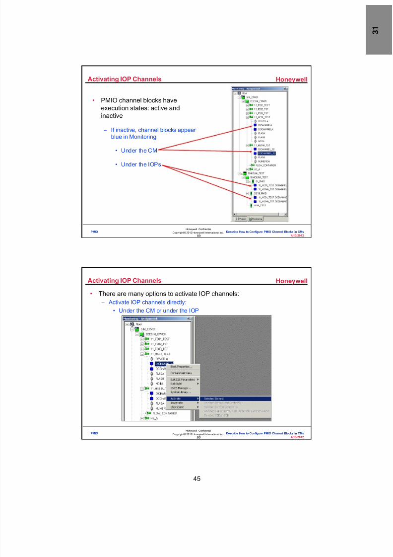
8/9/2019 Student Course Book- Automation
http://slidepdf.com/reader/full/student-course-book-automation 973/1165
45
Honeywell
Honeywell ConfidentialCopyright © 2012 Honeywell International Inc.
4/13/201289
• PMIO channel blocks haveexecution states: active andinactive
– If inactive, channel blocks appearblue in Monitoring
• Under the CM
• Under the IOPs
Activating IOP Channels
PMIO Describe How to Configure PMIO Channel Blocks in CMs
Honeywell
Honeywell ConfidentialCopyright © 2012 Honeywell International Inc.
4/13/201290
Activating IOP Channels
• There are many options to activate IOP channels: – Activate IOP channels directly:
• Under the CM or under the IOP
PMIO Describe How to Configure PMIO Channel Blocks in CMs

8/9/2019 Student Course Book- Automation
http://slidepdf.com/reader/full/student-course-book-automation 974/1165
46
Honeywell
Honeywell ConfidentialCopyright © 2012 Honeywell International Inc.
4/13/201291
• There are many options to activate IOP channels
– Activate from the CM
• With the CM
• Without the CM
Activating IOP Channels
PMIO Describe How to Configure PMIO Channel Blocks in CMs
Honeywell
Honeywell ConfidentialCopyright © 2012 Honeywell International Inc.
4/13/201292
Channels in the Monitor Tab
• Activation causes channel blocksto turn green
– Under the CM
– Under the IOPs
PMIO Describe How to Configure PMIO Channel Blocks in CMs

8/9/2019 Student Course Book- Automation
http://slidepdf.com/reader/full/student-course-book-automation 975/1165
47
Honeywell
Honeywell ConfidentialCopyright © 2012 Honeywell International Inc.
4/13/201293
Deleting IOP Channels
• IOP channels cannot be deletedfrom the IOL
• The only way to delete IOPchannels is to delete the CM thatuses them
PMIO Describe How to Configure PMIO Channel Blocks in CMs
Honeywell
Honeywell ConfidentialCopyright © 2012 Honeywell International Inc.
4/13/201294
Question 2: Activating and Deleting IOP Channels
Incorrect. An IOP channel block is not delete d
from its IOL. It can only be deleted bydeleting the CM that contains it.
Click anywhere to continue.
Incorrect. An IOP channel block is not delete d
from its IOL. It can only be deleted bydeleting the CM that contains it.
Click anywhere to continue.
Incorrect. An IOP channel block is not delete d
from its IOL. It can only be deleted bydeleting the CM that contains it.
Click anywhere to continue.
Correct! An IOP channel block is not deleted
from its IOL. It can only be deleted bydeleting the CM that contains it.
Click anywhere to continue.
Correct - Click anywhere to continueIncorrect - Click anywhere to continueYou answered this correctly!
Your answer:The correct answer is:
You did not answer this question completelyYou must answer the question beforecontinuing
Submit Clear
An IOP channel block is not: A) Activated from the CM with or without
activating the CM
B) Activated directly under the CM or under the IOP in the Monitoring tab
C) Green in the Monitoring tab when it hasbeen activated
D) Deleted from its IOL
PMIO Describe How to Configure PMIO Channel Blocks in CMs

8/9/2019 Student Course Book- Automation
http://slidepdf.com/reader/full/student-course-book-automation 976/1165
48
Honeywell
Honeywell ConfidentialCopyright © 2012 Honeywell International Inc.
4/13/201295
• A PMIO channel block:
– Can be added and assigned to a CM from the Library Tab (PMIO tree) orfrom the Project Tab
– Is inactive or blue in Monitoring until activated when it turns green
– Can be activated from the CM with or without activating the CM
– Can be activated directly under the CM or under the IOP in the Monitoringtab
– Can be deleted only by deleting the CM that contains it
Summary
PMIO Describe How to Configure PMIO Channel Blocks in CMs
Honeywell
Honeywell ConfidentialCopyright © 2012 Honeywell International Inc.
4/13/201296
Conclusion
Describe How to Configure PMIO Channel Blocks in CM
CompletionCertificate
Proceed to the next lesson in your course material
PMIO Describe How to Configure PMIO Channel Blocks in CMs
8/9/2019 Student Course Book- Automation
http://slidepdf.com/reader/full/student-course-book-automation 977/1165
49
97
Honeywell ConfidentialCopyright © 2012 Honeywell International Inc.
4/13/2012
Describe PMIO Configuration in a C300System
PMIO Describe PMIO Configuration in a C300 SystemPMIO Describe PMIO Configuration in a C300 System
Honeywell
Honeywell ConfidentialCopyright © 2012 Honeywell International Inc.
4/13/201298
Overview
• In this lesson you will learn about the configuration of PMIO in C300
PMIO Describe PMIO Configuration in a C300 System

8/9/2019 Student Course Book- Automation
http://slidepdf.com/reader/full/student-course-book-automation 978/1165
50
Honeywell
Honeywell ConfidentialCopyright © 2012 Honeywell International Inc.
4/13/201299
PMIO Configuration in C300
• C300 has 2 IOLINK’s by default – To configure PMIO in C300, IOFAMILY property of the IOLINK must be set
to PM_IO_TYPE
PMIO Describe PMIO Configuration in a C300 System
Honeywell
Honeywell ConfidentialCopyright © 2012 Honeywell International Inc.
4/13/2012100
Add IOPs
• Add IOP modules to the IOLINK
– Click and drag from Library to Project
– Or select from I/O Modules
PMIO Describe PMIO Configuration in a C300 System

8/9/2019 Student Course Book- Automation
http://slidepdf.com/reader/full/student-course-book-automation 979/1165
51
Honeywell
Honeywell ConfidentialCopyright © 2012 Honeywell International Inc.
4/13/2012101
IOP Assignment
• The IO modules must be assigned to the IOLINK which is configured forPMIO.
• Improper assignment gives an Assignment error
PMIO Describe PMIO Configuration in a C300 System
Honeywell
Honeywell ConfidentialCopyright © 2012 Honeywell International Inc.
4/13/2012102
IOP Configuration and Load
• Procedure to configure and load an IOP in C300 is similar to IOPconfiguration and load in C200/C200E
PMIO Describe PMIO Configuration in a C300 System

8/9/2019 Student Course Book- Automation
http://slidepdf.com/reader/full/student-course-book-automation 980/1165
52
Honeywell
Honeywell ConfidentialCopyright © 2012 Honeywell International Inc.
4/13/2012103
Conclusion
Describe PMIO Configuration in a C300 System
CompletionCertificate
Proceed to the PMIO lab exercises.
PMIO Describe PMIO Configuration in a C300 System
Honeywell
Honeywell ConfidentialCopyright © 2012 Honeywell International Inc.
4/13/2012104
This page intentionally left blank
PMIO Describe PMIO Configuration in a C300 System

8/9/2019 Student Course Book- Automation
http://slidepdf.com/reader/full/student-course-book-automation 981/1165
4/13/2012 Copyright © 2012 Honeywell International Inc. 1
HPS Automation College written permission required to distributeHoneywell Confidential and Proprietary
Topic: PMIO
Contents
Configure an I/O Link Module (IOLIM) for C200E ................................................................................. 3
Configure Digital, Analog and Hart IOPs ............................................................................................. 13
Assign, Load, and Activate PMIO for C200E ...................................................................................... 29
Assign, Load, and Activate PMIO for C300 ......................................................................................... 39
Configure a Continuous Control Strategy with PMIO .......................................................................... 49
Load, Activate, and Operate CMs with PMIO ...................................................................................... 75

8/9/2019 Student Course Book- Automation
http://slidepdf.com/reader/full/student-course-book-automation 982/1165
2 Copyright © 2012 Honeywell International Inc. 4/13/2012
HPS Automation College written permission required to distributeHoneywell Confidential and Proprietary
This page was intentionally left blank.

8/9/2019 Student Course Book- Automation
http://slidepdf.com/reader/full/student-course-book-automation 983/1165
PMIO
Configure an I/O Link Module (IOLIM) for C200E
4/13/2012 Copyright © 2012 Honeywell International Inc. 3
HPS Automation College written permission required to distributeHoneywell Confidential and Proprietary
Configure an I/O Link Module (IOLIM) for C200E
Practice
Objective
After completing this lesson you will be able to configure a SIMIOLIM and its associated I/O Link(IOL).
• Configure a SIMIOLIM with the proper settings in Control Builder
• Configure an I/O Link (IOL) with the proper settings in Control Builder
Introduction
The purpose of this lesson is to familiarize you with the methods of configuring I/O Link Modules(IOLIMs) in the Experion PKS system. The following procedures are introduced in this lab.
• Configure an SIMIOLIM
Note
If you are using SIM-C300 / C300 in class, skip this portion of the lab.

8/9/2019 Student Course Book- Automation
http://slidepdf.com/reader/full/student-course-book-automation 984/1165
PMIO
Configure an I/O Link Module (IOLIM) for C200E
4 Copyright © 2012 Honeywell International Inc. 4/13/2012
HPS Automation College written permission required to distributeHoneywell Confidential and Proprietary
Configure an IOLIM
Use the following procedure to configure and add a SIMIOLIM to a project.
Step Action1 Read the important information in the Attention box:
ATTENTION
Only students configuring a C200E should completethis portion of the lab.
Students configuring a C300 should go to the followingportion of the lab:“Configure Digital, Analog and Hart IOPs”
Look on the Contents page (at the beginning of thislab) to find the page number.

8/9/2019 Student Course Book- Automation
http://slidepdf.com/reader/full/student-course-book-automation 985/1165
PMIO
Configure an I/O Link Module (IOLIM) for C200E
4/13/2012 Copyright © 2012 Honeywell International Inc. 5
HPS Automation College written permission required to distributeHoneywell Confidential and Proprietary
Step Action
2 Select SIMIOLIM from the list of Interface Modules to open the configuration form.
From the File menu, select New>Interface Modules>SIMIOLIM – IO Link InterfaceSimulator.
ATTENTION
The above method of adding an SIMIOLIM to theProject is the same as we used, previously.
3 Enter the following details:
Tag Name: IOLIM0303
Item Name: IOLIM0303_item
Description: IOLIM Simulation
`

8/9/2019 Student Course Book- Automation
http://slidepdf.com/reader/full/student-course-book-automation 986/1165
PMIO
Configure an I/O Link Module (IOLIM) for C200E
6 Copyright © 2012 Honeywell International Inc. 4/13/2012
HPS Automation College written permission required to distributeHoneywell Confidential and Proprietary
Step Action
4 Enter the Host Name (the name of your assigned Server).
ATTENTION
Once the Host Name is added press enter. The HostIP Address should appear automatically.
5 Click on the Server Displays tab.
6 Enter the following information:
Group: 51
Position: 3
Group Parameter: IOLIM0303

8/9/2019 Student Course Book- Automation
http://slidepdf.com/reader/full/student-course-book-automation 987/1165
PMIO
Configure an I/O Link Module (IOLIM) for C200E
4/13/2012 Copyright © 2012 Honeywell International Inc. 7
HPS Automation College written permission required to distributeHoneywell Confidential and Proprietary
Step Action
7 Click OK to add the configured IOLIM to Project Tree .

8/9/2019 Student Course Book- Automation
http://slidepdf.com/reader/full/student-course-book-automation 988/1165
PMIO
Configure an I/O Link Module (IOLIM) for C200E
8 Copyright © 2012 Honeywell International Inc. 4/13/2012
HPS Automation College written permission required to distributeHoneywell Confidential and Proprietary
Configure an IO Link
Use the following procedure to configure the I/O Link.
Step Action
1 Click the “+” icon adjacent to IOLIM0303 to display the SIMIOLINK_###.
ATTENTION
You might get a different number adjacent toSIMIOLINK. In this case it is 679.
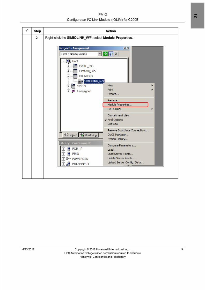
8/9/2019 Student Course Book- Automation
http://slidepdf.com/reader/full/student-course-book-automation 989/1165
PMIO
Configure an I/O Link Module (IOLIM) for C200E
4/13/2012 Copyright © 2012 Honeywell International Inc. 9
HPS Automation College written permission required to distributeHoneywell Confidential and Proprietary
Step Action
2 Right-click the SIMIOLINK_###, select Module Properties .

8/9/2019 Student Course Book- Automation
http://slidepdf.com/reader/full/student-course-book-automation 990/1165
PMIO
Configure an I/O Link Module (IOLIM) for C200E
10 Copyright © 2012 Honeywell International Inc. 4/13/2012
HPS Automation College written permission required to distributeHoneywell Confidential and Proprietary
Step Action
3 In the Main tab, enter
Tag Name : IOLINK0303
Item Name : IOLINK0303_item
Description : IOLINK Simulation.
ATTENTION
The I/O LINK is the software window for the PMIO.There will be numerous parameters in the Monitor Tab(and therefore in the Station Point Detail) that providea view to the status of the various PMIO racksassociated with this IOLIM.
4 Click on the Server Displays tab.

8/9/2019 Student Course Book- Automation
http://slidepdf.com/reader/full/student-course-book-automation 991/1165
PMIO
Configure an I/O Link Module (IOLIM) for C200E
4/13/2012 Copyright © 2012 Honeywell International Inc. 11
HPS Automation College written permission required to distributeHoneywell Confidential and Proprietary
Step Action
5 Enter the following information:
Group: 51
Position: 4
Group Parameter: IOLINK0303
6 Click OK .

8/9/2019 Student Course Book- Automation
http://slidepdf.com/reader/full/student-course-book-automation 992/1165
PMIO
Configure an I/O Link Module (IOLIM) for C200E
12 Copyright © 2012 Honeywell International Inc. 4/13/2012
HPS Automation College written permission required to distributeHoneywell Confidential and Proprietary
This page was intentionally left blank.
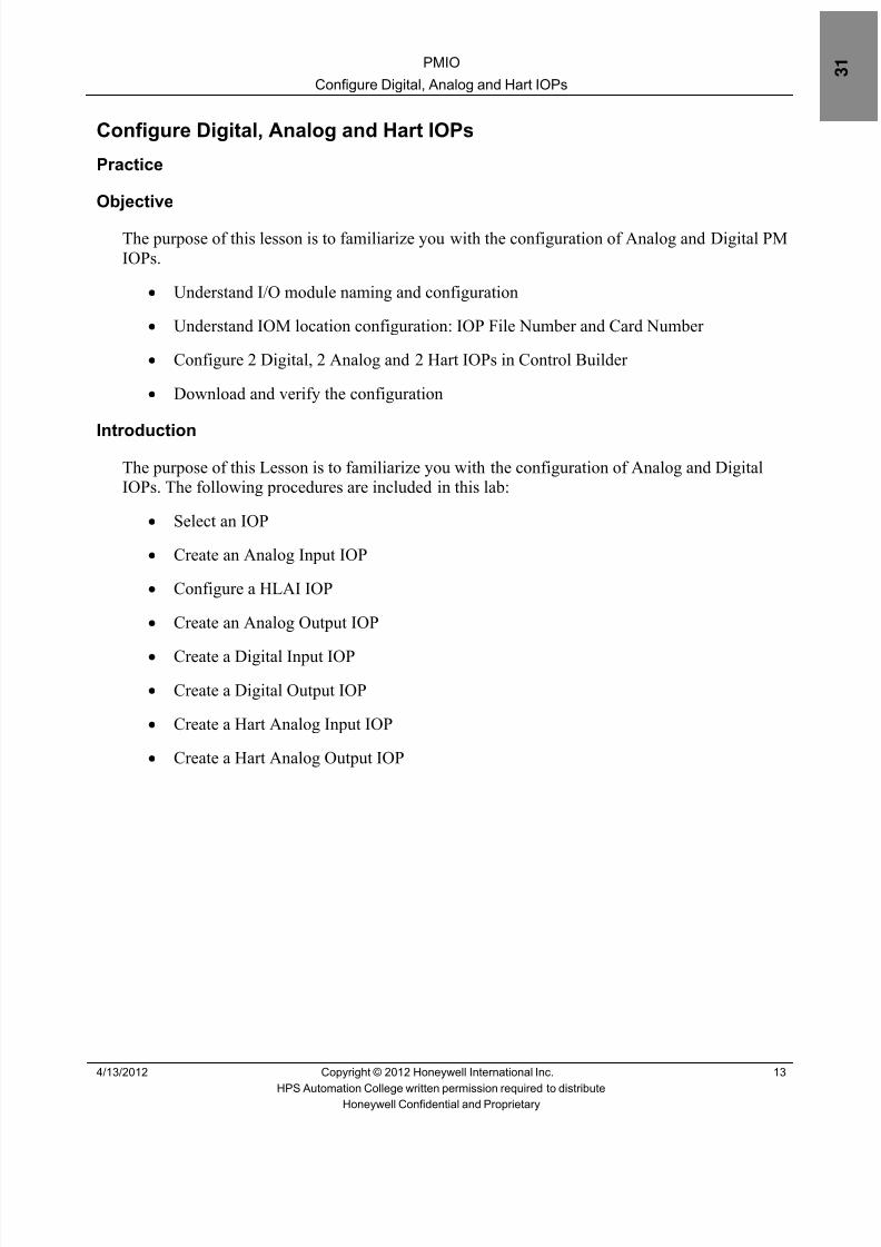
8/9/2019 Student Course Book- Automation
http://slidepdf.com/reader/full/student-course-book-automation 993/1165
PMIO
Configure Digital, Analog and Hart IOPs
4/13/2012 Copyright © 2012 Honeywell International Inc. 13
HPS Automation College written permission required to distributeHoneywell Confidential and Proprietary
Configure Digital, Analog and Hart IOPs
Practice
Objective
The purpose of this lesson is to familiarize you with the configuration of Analog and Digital PMIOPs.
• Understand I/O module naming and configuration
• Understand IOM location configuration: IOP File Number and Card Number
• Configure 2 Digital, 2 Analog and 2 Hart IOPs in Control Builder
• Download and verify the configuration
IntroductionThe purpose of this Lesson is to familiarize you with the configuration of Analog and DigitalIOPs. The following procedures are included in this lab:
• Select an IOP
• Create an Analog Input IOP
• Configure a HLAI IOP
• Create an Analog Output IOP
• Create a Digital Input IOP• Create a Digital Output IOP
• Create a Hart Analog Input IOP
• Create a Hart Analog Output IOP

8/9/2019 Student Course Book- Automation
http://slidepdf.com/reader/full/student-course-book-automation 994/1165
PMIO
Configure Digital, Analog and Hart IOPs
14 Copyright © 2012 Honeywell International Inc. 4/13/2012
HPS Automation College written permission required to distributeHoneywell Confidential and Proprietary
Procedure
Select an IOP
Step Action
1 Read the important information in the Attention box:
ATTENTION
This portion of the lab should be completed by ALLstudents – those configuring a C200E, and also thoseconfiguring a C300.
2 Use one of the following two methods to add an IOP .
Menu Method :
From the File menu, select New > I/O Modules > PMIO > [IOP selection].

8/9/2019 Student Course Book- Automation
http://slidepdf.com/reader/full/student-course-book-automation 995/1165
PMIO
Configure Digital, Analog and Hart IOPs
4/13/2012 Copyright © 2012 Honeywell International Inc. 15
HPS Automation College written permission required to distributeHoneywell Confidential and Proprietary
Step Action
3 Library Method :
Navigate to the Library Tree window. Expand the PMIO directory and select an IOP.
If the Project Tree window is also open, the chosen IOP can be dragged to a blankarea (which adds it to Unassigned), or the IOP can be dragged directly to theappropriate IOLINK
ATTENTION
There are many choices in Control Builder under theI/O Modules menu pull down. All I/O types can beaccessed and added to a project using either theMenu method or the Library method.

8/9/2019 Student Course Book- Automation
http://slidepdf.com/reader/full/student-course-book-automation 996/1165
PMIO
Configure Digital, Analog and Hart IOPs
16 Copyright © 2012 Honeywell International Inc. 4/13/2012
HPS Automation College written permission required to distributeHoneywell Confidential and Proprietary
Create an Analog Input IOP
The following procedure creates an analog input IOP.
Step Action
1 Arrange Project and Library windows in Control Builder as shown in Step 3.
2 Navigate to the Library Tree window in Control Builder and expand the PMIO library.
3 Drag and drop the HLAI IOP from the PMIO library to the blank area at the bottom of theProject Tree window.
A configuration dialog box automatically opens when the IOP is added to the projectwindow

8/9/2019 Student Course Book- Automation
http://slidepdf.com/reader/full/student-course-book-automation 997/1165
PMIO
Configure Digital, Analog and Hart IOPs
4/13/2012 Copyright © 2012 Honeywell International Inc. 17
HPS Automation College written permission required to distributeHoneywell Confidential and Proprietary
Step Action
4 Enter the following in the configuration dialog box:
Destination Tagnames : CPM3AI_F3C01
Destination Item Names : CPM3AI_F3C01_item
ATTENTION
It is a good idea for the module name to reflect thetype of module you are using and its location. This willmake tracking easier in the future when you add moremodules to your system. We chose CPM3AI_F3C01 . This refers to the CPM associated with the IOLIM , theIOP type, the rack number, and the card number,assuming card File 3 and card 1.
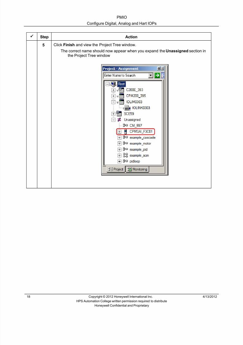
8/9/2019 Student Course Book- Automation
http://slidepdf.com/reader/full/student-course-book-automation 998/1165
PMIO
Configure Digital, Analog and Hart IOPs
18 Copyright © 2012 Honeywell International Inc. 4/13/2012
HPS Automation College written permission required to distributeHoneywell Confidential and Proprietary
Step Action
5 Click Finish and view the Project Tree window.
The correct name should now appear when you expand the Unassigned section inthe Project Tree window

8/9/2019 Student Course Book- Automation
http://slidepdf.com/reader/full/student-course-book-automation 999/1165
PMIO
Configure Digital, Analog and Hart IOPs
4/13/2012 Copyright © 2012 Honeywell International Inc. 19
HPS Automation College written permission required to distributeHoneywell Confidential and Proprietary
Configure a HLAI IOP
The following procedure configures a HLAI IOP.
Step Action
1 Double-click CPM3AI_F3C01 in the Unassigned section of the Project Treewindow to display the Parameter Configuration form.
2 Enter the following information in the appropriate field in the Main tab:
Description: Test Strategy PMIO AI ModuleIOP Number: 1I/O Link Scan Rate: Accept the default: 250_ms
ATTENTION
PMIO has the ability to optimize communication on theIO Link. Each IOP can have its own Scan Rate. The IOLink bandwidth is divided into 1000 Link Units and theycan be used most effectively by determining how fastupdates are needed by the CMs which will use the IOsignals, and setting the Scan Rate accordingly. A linkunit is roughly equivalent to one parameter per second.
For a complete write-up on Link Units, including a LinkUnit Calculation tool, see Knowledge Builder,Experion PKS R400 > Planning and Design >
Control Hardware Planning Guide > ProcessManager IO Integration Planning > SystemTopology and Performance Considerations .

8/9/2019 Student Course Book- Automation
http://slidepdf.com/reader/full/student-course-book-automation 1000/1165
PMIO
Configure Digital, Analog and Hart IOPs
20 Copyright © 2012 Honeywell International Inc. 4/13/2012
HPS Automation College written permission required to distributeHoneywell Confidential and Proprietary
Step Action
3 • I/O Processor Modules may reside in up to eight PMIO card files.• Each IOP has a software designator: IOP Number• Each IOP has a physical location consisting of:
- File Number (1-8)- Card Number (1-15)
• Redundant IOPs use the same IOP Number designator:
Each partner has a unique File number and Card number. In class, enterthe following:
CPM3AI_F3C01 is in File 3, Card 1 , non redundant, and is IOP Number 1
ATTENTION
PMIO modules can be mounted in any slot of any cardfile. Therefore, part of the IOP configuration is thephysical location. This consists of the file number,which is set up using jumpers on the chassis backplane, and the slot number counted from left to rightstarting at 1.
The above configuration uses card file three and slotone and incorporates this information into the IOPname. If your assigned AI module is in a differentlocation, modify your work accordingly. The IOPNumber assigned to a module does not have to be thesame as the card number. Recall that an IOLIM cansupport up to 40 IOPs. The IOP numbers for thesewould be from 1 to 40. The card numbers are related tofile slot locations and run from 1 to 15.

8/9/2019 Student Course Book- Automation
http://slidepdf.com/reader/full/student-course-book-automation 1001/1165
PMIO
Configure Digital, Analog and Hart IOPs
4/13/2012 Copyright © 2012 Honeywell International Inc. 21
HPS Automation College written permission required to distributeHoneywell Confidential and Proprietary
Step Action
4 Click the Server Displays tab.
• The Point Detail Display and the Group Detail Display are already filled.This is true for hardware objects and SCMs. Input this information for CMs
5 Add CPM3AI_F3C01 to Group # 51, Pos # 5.
6 Click OK.

8/9/2019 Student Course Book- Automation
http://slidepdf.com/reader/full/student-course-book-automation 1002/1165
PMIO
Configure Digital, Analog and Hart IOPs
22 Copyright © 2012 Honeywell International Inc. 4/13/2012
HPS Automation College written permission required to distributeHoneywell Confidential and Proprietary
Create an Analog Output IOP
The following procedure creates an analog output IOP.
Step Action
1 Set up Control Builder making the Project Tree window, Library Tree window, andMonitoring Tree window visible.
2 From the Library window, expand the PMIO library.
3 Drag and drop the IOP AO16 from the PMIO library to the blank space at the bottom ofthe project tree.
A configuration dialog box automatically opens when the IOP is added to the projectwindow
4 Enter the following
Destination Tagnames: CPM3AO_F3C02 .
Destination Item Names: CPM3AO_F3C02_item .
ATTENTION
This configuration assumes the IOP is located in File3, Card 2.
5 Click Finish .
6 Double click CPM3AO_F3C02 in the Project Tree under the Unassigned section.
7 Enter the following information in the Parameters form.Main tab:
Description: Test Strategy PMIO AO ModuleIOP Number: 2File: 3Card: 2Scan Rate: 250_MSFailure Option: Hold
Server Displays tab:
Group: 51Position: 6
Group Parameter: CPM3AO_F3C02
8 Click OK .

8/9/2019 Student Course Book- Automation
http://slidepdf.com/reader/full/student-course-book-automation 1003/1165
PMIO
Configure Digital, Analog and Hart IOPs
4/13/2012 Copyright © 2012 Honeywell International Inc. 23
HPS Automation College written permission required to distributeHoneywell Confidential and Proprietary
Create a Digital Input IOP
The following procedure creates a digital input IOP.
Step Action
1 From the File menu select:
New > I/O Modules > PMIO > DI24V – 24 Volt Digital Input, 32 ch
The method shown above is another way of adding a new I/O Module rather than themethod used in prior labs
ATTENTION
Here we use the File pull down to add a new IOP. Onebenefit of this method is that you are able to see thedetails of the Modules (number of channels,voltage/current, Isolated/non-Isolated) directly in the
selection menu.

8/9/2019 Student Course Book- Automation
http://slidepdf.com/reader/full/student-course-book-automation 1004/1165
PMIO
Configure Digital, Analog and Hart IOPs
24 Copyright © 2012 Honeywell International Inc. 4/13/2012
HPS Automation College written permission required to distributeHoneywell Confidential and Proprietary
Step Action
2 Enter the following information:
Main tab:
Tagname: CPM3DI_F3C03Item Name: CPM3DI_F3C03_itemDescription: Test Strategy PMIO DI Module IOP Number: 3 File: 3 Card: 3 Scan Rate: 100_MS
Server Displays tab:
Group: 51 Position: 7Group Parameter: CPM3DI_F3C03
3 Click OK .

8/9/2019 Student Course Book- Automation
http://slidepdf.com/reader/full/student-course-book-automation 1005/1165

8/9/2019 Student Course Book- Automation
http://slidepdf.com/reader/full/student-course-book-automation 1006/1165
PMIO
Configure Digital, Analog and Hart IOPs
26 Copyright © 2012 Honeywell International Inc. 4/13/2012
HPS Automation College written permission required to distributeHoneywell Confidential and Proprietary
Create a Hart Analog Input IOP
The following procedure creates a Hart Analog Input IOP.
Step Action
1 From the File menu select:
New>I/O Modules>PMIO>HLAIHART – High Level Analog Input, Hart Capable, 16ch
Using the Menu Method to create your new I/O Module will open the Main tab of ModuleProperties.
2 Enter the following information in the Parameters form:
Main tab:
Tagname: CPM3HAI_F3C11Item Name: CPM3HAI_F3C11_itemModule Description: Test Strategy PMIO HLAI Module IOP Number: 5 File: 3 Card: 11 Scan Rate: 250_MS
Server Displays tab:
Group: 52 Position: 1Group Parameter: CPM3HAI_F3C11
3 Click OK .

8/9/2019 Student Course Book- Automation
http://slidepdf.com/reader/full/student-course-book-automation 1007/1165
PMIO
Configure Digital, Analog and Hart IOPs
4/13/2012 Copyright © 2012 Honeywell International Inc. 27
HPS Automation College written permission required to distributeHoneywell Confidential and Proprietary
Creates a Hart Analog Output IOP
The following procedure creates a Hart Analog Output IOP.
Step Action
1 From the File menu select:
New>I/O Modules>PMIO>AO16HART– Analog Output, Hart Capable, 16ch
Using the Menu Method to create your new I/O Module will open the Main tab of ModuleProperties.
2 Enter the following information in the Parameters form:
Main tab:
Tagname: CPM3HAO_F3C12Item Name: CPM3HAO_F3C12_item Description: Test Strategy PMIO HAO Module IOP Number: 6 File: 3 Card: 12 Scan Rate: 250_MS
Server Displays tab:
Group: 52 Position: 2Group Parameter: CPM3HAO_F3C12
3 Click OK .

8/9/2019 Student Course Book- Automation
http://slidepdf.com/reader/full/student-course-book-automation 1008/1165
PMIO
Configure Digital, Analog and Hart IOPs
28 Copyright © 2012 Honeywell International Inc. 4/13/2012
HPS Automation College written permission required to distributeHoneywell Confidential and Proprietary
This page was intentionally left blank.

8/9/2019 Student Course Book- Automation
http://slidepdf.com/reader/full/student-course-book-automation 1009/1165
PMIO
Assign, Load, and Activate PMIO for C200E
4/13/2012 Copyright © 2012 Honeywell International Inc. 29
HPS Automation College written permission required to distributeHoneywell Confidential and Proprietary
Assign, Load, and Activate PMIO for C200E
Practice
Objective
After completing this lesson, you will be able to assign, load, and activate IOPs in ControlBuilder for C200E and verify that the IOP database has been validated.
Introduction
The purpose of this lesson is to familiarize you with the configuration of Analog and DigitalIOPs.
The following procedures are introduced in this lab:
• Assign IOPs to the I/O Link• Load the IOLIM, IOLINK, and IOPs• Verify the load• Verify the IOP database has been validated

8/9/2019 Student Course Book- Automation
http://slidepdf.com/reader/full/student-course-book-automation 1010/1165
PMIO
Assign, Load, and Activate PMIO for C200E
30 Copyright © 2012 Honeywell International Inc. 4/13/2012
HPS Automation College written permission required to distributeHoneywell Confidential and Proprietary
Procedure
Assign IOPs to the IOLINK
The following procedure assigns IOPs to an I/O Link.
Step Action
1 Read the important information in the Attention box:
ATTENTION
Only students configuring a C200E should completethis portion of the lab.
Students configuring a C300 should go to the following
portion of the lab:“Assign, Load, and Activate PMIO for C300”Look on the Contents page (at the beginning of thislab) to find the page number.
2 From the Control Builder Edit menu, click Execution Environment Assignment todisplay the Execution Environment Assignment screen.
ATTENTION
When configuring Series A IO modules, we assignthem to a CEE prior to loading. PMIOs are assigned toan IOLINK and not a CEE. Depending on the type ofmodule selected in the IOMs tab, IOLINK or CEEselections will appear in the Assign To section.
3 Locate the Available Modulessection on the left side of thewindow and Click the tablabeled IOMs.
4 Locate your destination I/O Link
IOLINK0303

8/9/2019 Student Course Book- Automation
http://slidepdf.com/reader/full/student-course-book-automation 1011/1165
PMIO
Assign, Load, and Activate PMIO for C200E
4/13/2012 Copyright © 2012 Honeywell International Inc. 31
HPS Automation College written permission required to distributeHoneywell Confidential and Proprietary
Step Action
5 If your Project has multiple I/OLinks, then click the applicabledestination I/O Link from the
window labeled Assign To:
If you only have one I/O Link, it will be selected bydefault.
6 Use the <Ctrl> or Shift key and select all the IOMs:
CPM3AI_F3C01CPM3AO_F3C02 CPM3DI_F3C03CPM3DO_F3C04CPM3HAI_F3C11CPM3HAO_F3C12
7 Select your destination IOLINK (IOLINK0303 created previously) from the Assign To list.
8 Click the Assign button. After a few seconds, your IOPs will appear in the section of thewindow labeled Assigned Modules .

8/9/2019 Student Course Book- Automation
http://slidepdf.com/reader/full/student-course-book-automation 1012/1165
PMIO
Assign, Load, and Activate PMIO for C200E
32 Copyright © 2012 Honeywell International Inc. 4/13/2012
HPS Automation College written permission required to distributeHoneywell Confidential and Proprietary
Step Action
9 Click Close and observe that your IOPs now appear in the Project tab assigned toIOLINK0303 .
ATTENTION
An alternative to this is to manually drag the IOP fromUnassigned to the IOLINK
IOPs can be directly assigned to an IOLINK, whenadding them from the library.

8/9/2019 Student Course Book- Automation
http://slidepdf.com/reader/full/student-course-book-automation 1013/1165
PMIO
Assign, Load, and Activate PMIO for C200E
4/13/2012 Copyright © 2012 Honeywell International Inc. 33
HPS Automation College written permission required to distributeHoneywell Confidential and Proprietary
Load the IOLIM, IOLINK, and IOPs
This procedure loads the IOLIM, IOLINK, and IOPs.
Step Action
1 In the Project Tree window, right click IOLIM0303 to open the shortcut menu, and selectLoad with Contents .
There are two commands you may use to load objects to your IOLIM: Load , andLoad With Contents . The Load command loads the selected objects to yourIOLIM. The Load With Contents command loads the selected object along withall objects assigned to it. For the IOLIM, contents are itself along with its IOLINKand IOPs. For the IOLINK, contents are itself and its IOPs.
Load With Contents can be accessed from the Controller menu or by right clickingon the IOLIM or IOLINK.
In this lab exercise use the Load With Contents command.

8/9/2019 Student Course Book- Automation
http://slidepdf.com/reader/full/student-course-book-automation 1014/1165
PMIO
Assign, Load, and Activate PMIO for C200E
34 Copyright © 2012 Honeywell International Inc. 4/13/2012
HPS Automation College written permission required to distributeHoneywell Confidential and Proprietary
Step Action
2 Click Continue in the Load window. Verify that the IOLINK and all the IOPs will beloaded.
3 DO NOT select the Automatic Post Load State check box.
ATTENTION
You will activate the IOPs manually.
4 Click OK .• If there are no errors, the Load Dialog automatically closes.• If you get a configuration error, close the load and determine the problem before
proceeding•
The usual reasons are:- Wrong IOP type selected- Wrong slot configured

8/9/2019 Student Course Book- Automation
http://slidepdf.com/reader/full/student-course-book-automation 1015/1165
PMIO
Assign, Load, and Activate PMIO for C200E
4/13/2012 Copyright © 2012 Honeywell International Inc. 35
HPS Automation College written permission required to distributeHoneywell Confidential and Proprietary
Verify the Load
Follow this procedure to verify that the IOP has loaded correctly.
Step Action
1 After loading successfully, go to the Monitoring Tree window.
2 The IOLIM will already be activated (green in color).
The IOLINK is also active.
3 The IOPs will be blue in color, indicating their state is inactive.

8/9/2019 Student Course Book- Automation
http://slidepdf.com/reader/full/student-course-book-automation 1016/1165
PMIO
Assign, Load, and Activate PMIO for C200E
36 Copyright © 2012 Honeywell International Inc. 4/13/2012
HPS Automation College written permission required to distributeHoneywell Confidential and Proprietary
Step Action
4 Call up Group 51 in Station and examine the IOPs.
The green color adjacent to the Database Valid item indicates that the database isvalidated.
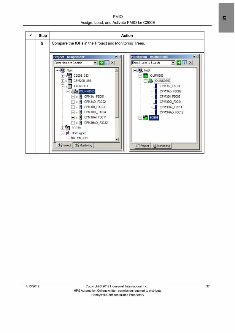
8/9/2019 Student Course Book- Automation
http://slidepdf.com/reader/full/student-course-book-automation 1017/1165
PMIO
Assign, Load, and Activate PMIO for C200E
4/13/2012 Copyright © 2012 Honeywell International Inc. 37
HPS Automation College written permission required to distributeHoneywell Confidential and Proprietary
Step Action
5 Compare the IOPs in the Project and Monitoring Trees.

8/9/2019 Student Course Book- Automation
http://slidepdf.com/reader/full/student-course-book-automation 1018/1165
PMIO
Assign, Load, and Activate PMIO for C200E
38 Copyright © 2012 Honeywell International Inc. 4/13/2012
HPS Automation College written permission required to distributeHoneywell Confidential and Proprietary
Step Action
6 Expand the DI IOP in Project.• The contents of a Project IOP are its
channels• The channels do not appear in the
contents of the IOP in the Monitoringtab until they are downloaded in CMswhich use the channels
• Once a channel is assigned to an IOblock in a CM, the channel namedisplayed in Project and Monitoring isthe name of the IO block:
CM name.FB name
NOTE : There are two ways to add IOPchannels to CMs:1. Drag the channel from the IOP in theProject tab to the CM.2. Drag the channel from the IOP type inLibrary to the CM.The first methodsaves having to assign the channel toan IOP as it is already selected from anIOP contents tree. The second methodrequires assignment to a particular IOPand channel. This is done by rightclicking on the IO block in the CM andselecting Function Block Assign.
7 Select all the IOPs from the Monitoring Tree window and activate them.
ATTENTION
To activate the IOP right click on the IOP and selectActivate > Selected Item(s) .

8/9/2019 Student Course Book- Automation
http://slidepdf.com/reader/full/student-course-book-automation 1019/1165
PMIO
Assign, Load, and Activate PMIO for C300
4/13/2012 Copyright © 2012 Honeywell International Inc. 39
HPS Automation College written permission required to distributeHoneywell Confidential and Proprietary
Assign, Load, and Activate PMIO for C300
Practice
Objective
After completing this lesson, you will be able to assign, load, and activate IOPs in ControlBuilder for C300 and verify that the IOP database has been validated.
Introduction
The purpose of this lesson is to familiarize you with the configuration of Analog and DigitalIOPs
The following procedures are introduced in this lab:
• Assign IOPs to the I/O Link• Load the IOLINK, and IOPs• Verify the load• Verify the IOP database has been validated

8/9/2019 Student Course Book- Automation
http://slidepdf.com/reader/full/student-course-book-automation 1020/1165
PMIO
Assign, Load, and Activate PMIO for C300
40 Copyright © 2012 Honeywell International Inc. 4/13/2012
HPS Automation College written permission required to distributeHoneywell Confidential and Proprietary
Procedure
Assign IOPs to the IOLINK
The following procedure assigns IOPs to an I/O Link.
Step Action
1 Read the important information in the Attention box:
ATTENTION
Only students configuring a C300 should complete thisportion of the lab.
Students configuring a C200E should go to the
following portion of the lab:“Configure a Continuous Control Strategy with PMIO”Look on the Contents page (at the beginning of thislab) to find the page number.
2 From the Control Builder Edit menu, click Execution Environment Assignment todisplay the Execution Environment Assignment screen
ATTENTION
When configuring Series C IO modules, we assignthem to a CEE prior to loading. PMIOs are assigned toan IOLINK and not a CEE. Depending on the type ofmodule selected in the IOMs tab, IOLINK or CEEselections will appear in the ‘Assign To’ section.
3 Locate the Available Modulessection on the left side of thewindow and click the tablabeled IOMs
4 Locate your destination I/O Link
PMIO_IOLINK

8/9/2019 Student Course Book- Automation
http://slidepdf.com/reader/full/student-course-book-automation 1021/1165
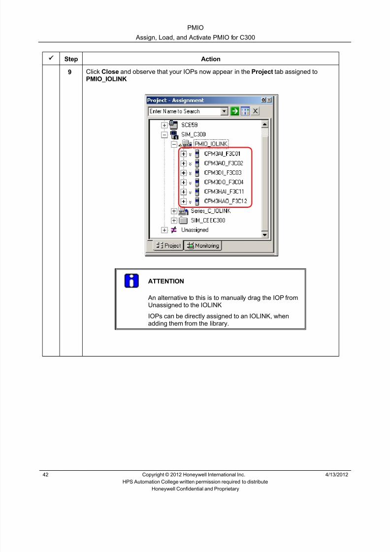
8/9/2019 Student Course Book- Automation
http://slidepdf.com/reader/full/student-course-book-automation 1022/1165
PMIO
Assign, Load, and Activate PMIO for C300
42 Copyright © 2012 Honeywell International Inc. 4/13/2012
HPS Automation College written permission required to distributeHoneywell Confidential and Proprietary
Step Action
9 Click Close and observe that your IOPs now appear in the Project tab assigned toPMIO_IOLINK
ATTENTION
An alternative to this is to manually drag the IOP fromUnassigned to the IOLINK
IOPs can be directly assigned to an IOLINK, whenadding them from the library.

8/9/2019 Student Course Book- Automation
http://slidepdf.com/reader/full/student-course-book-automation 1023/1165
PMIO
Assign, Load, and Activate PMIO for C300
4/13/2012 Copyright © 2012 Honeywell International Inc. 43
HPS Automation College written permission required to distributeHoneywell Confidential and Proprietary
Load the IOLINK, and IOPs
This procedure loads the IOLINK, and IOPs.
Step Action
1 In the Project Tree window, right click PMIO_IOLINK to open the shortcut menu, andselect Load with Contents
There are two commands you may use to load objects to your IOLIM: Load , andLoad With Contents . The Load command loads the selected objects to yourIOLINK. The Load With Contents command loads the selected object alongwith all objects assigned to it. For the IOLINK, contents are itself and its IOPs.
Load With Contents can be accessed from the Controller menu or by right clickingon the IOLIM or IOLINK.
In this lab exercise use the Load With Contents command.

8/9/2019 Student Course Book- Automation
http://slidepdf.com/reader/full/student-course-book-automation 1024/1165
PMIO
Assign, Load, and Activate PMIO for C300
44 Copyright © 2012 Honeywell International Inc. 4/13/2012
HPS Automation College written permission required to distributeHoneywell Confidential and Proprietary
Step Action
2 Click Continue in the Load window. Verify that the PMIO_IOLINK and all your IOPs areselected.
3 DO NOT select the Automatic Change ALL ….. check box.
ATTENTION
You will activate the IOPs manually.
4 Click OK .• If there are no errors, the Load Dialog automatically closes.• If you get a configuration error, close the load and determine the problem before
proceeding•
The usual reasons are:- Wrong IOP type selected- Wrong slot configured

8/9/2019 Student Course Book- Automation
http://slidepdf.com/reader/full/student-course-book-automation 1025/1165
PMIO
Assign, Load, and Activate PMIO for C300
4/13/2012 Copyright © 2012 Honeywell International Inc. 45
HPS Automation College written permission required to distributeHoneywell Confidential and Proprietary
Verify the Load
Follow this procedure to verify that the IOP has loaded correctly.
Step Action
1 After loading successfully, go to the Monitoring Tree window.
2 The PMIO_IOLINK will already be activated (green in color)
3 The IOP’s will be blue in color, indicating their state is inactive.

8/9/2019 Student Course Book- Automation
http://slidepdf.com/reader/full/student-course-book-automation 1026/1165
PMIO
Assign, Load, and Activate PMIO for C300
46 Copyright © 2012 Honeywell International Inc. 4/13/2012
HPS Automation College written permission required to distributeHoneywell Confidential and Proprietary
Step Action
4 Call up Group 51 in Station and examine the IOPs.
The green color adjacent to the Database Valid item indicates that the database isvalidated.

8/9/2019 Student Course Book- Automation
http://slidepdf.com/reader/full/student-course-book-automation 1027/1165
PMIO
Assign, Load, and Activate PMIO for C300
4/13/2012 Copyright © 2012 Honeywell International Inc. 47
HPS Automation College written permission required to distributeHoneywell Confidential and Proprietary
Step Action
5 Compare the IOPs in the Project and Monitoring Trees.

8/9/2019 Student Course Book- Automation
http://slidepdf.com/reader/full/student-course-book-automation 1028/1165
PMIO
Assign, Load, and Activate PMIO for C300
48 Copyright © 2012 Honeywell International Inc. 4/13/2012
HPS Automation College written permission required to distributeHoneywell Confidential and Proprietary
Step Action
6 Expand the DI IOP in Project.• The contents of a Project IOP are its
channels• The channels do not appear in the
contents of the IOP in the Monitoringtab until they are downloaded in CMswhich use the channels
• Once a channel is assigned to an IOblock in a CM, the channel namedisplayed in Project and Monitoring isthe name of the IO block:
CM name.FB name
NOTE : There are two ways to add IOPchannels to CMs:
1. Drag the channel from the IOP inthe Project tab to the CM.2. Drag the channel from the IOP typein Library to the CM.The first methodsaves having to assign the channel toan IOP as it is already selected froman IOP contents tree. The secondmethod requires assignment to aparticular IOP and channel. This isdone by right clicking on the IO blockin the CM and selecting Function Block
Assign.7 Select all the IOPs from the Monitoring Tree window and activate them.
ATTENTION
To activate the IOP right click on the IOP and selectActivate > Selected Item(s) .

8/9/2019 Student Course Book- Automation
http://slidepdf.com/reader/full/student-course-book-automation 1029/1165
PMIO
Configure a Continuous Control Strategy with PMIO
4/13/2012 Copyright © 2012 Honeywell International Inc. 49
HPS Automation College written permission required to distributeHoneywell Confidential and Proprietary
Configure a Continuous Control Strategy with PMIO
(This Lab is Optional)
Practice
Objective
After you complete this lesson you should be able to configure a continuous control strategy withPMIO and contrast it to Series A and Series C IO.
• Configure a PID loop CM using PMIODownload and verify the CM
Introduction
The purpose of this lesson is to provide the knowledge to configure a continuous control strategy,using PMIO.
The following procedures are included in this lab:
• Create and save a Control Module
• Configure a Control Module
• Assign CMs to the CEE
• Add Function Blocks to a CM
• Configure a PMIO AI Channel Block
• Configure a Data Acquisition Block• Configure a PID Block
• Move Pins on Function Blocks
• Configure an AO Block
• Finish your CM
• Configure a Hart temperature transmitter
Note:
If you are using SIM_C300 / C300, then assign the CM to CEE of SIM-C300 / C300.
IOLIM0303 and IOLINK0303 (Referred in this lab) will not be present if you are using SIM-C300 /C300. Use PMIO_IOLINK to access the IOP

8/9/2019 Student Course Book- Automation
http://slidepdf.com/reader/full/student-course-book-automation 1030/1165
PMIO
Configure a Continuous Control Strategy with PMIO
50 Copyright © 2012 Honeywell International Inc. 4/13/2012
HPS Automation College written permission required to distributeHoneywell Confidential and Proprietary
Procedure
Create and Save a Control Module
The following procedure creates and saves a Control Module.
Step Action
1 Read the important information in the Attention box:
ATTENTION
This portion of the lab should be completed by ALLstudents – those configuring a C200E, and also thoseconfiguring a C300.
2 Set up the Control Builder with both the Library and Project views visible.
3 Expand System from Library window and select CONTROLMODULE .
4 Drag and drop the Control Module into the open space at the bottom of the Project Root
ATTENTION
To create a Control Strategy, you must create a ControlModule and insert and connect function blocks. When youdrag and drop the CM to the Project root, it will appear underthe Unassigned node. Control Module names are sequentiallynumbered (for example, CM30, CM31, and so on). The newControl Module is automatically added to your Project.

8/9/2019 Student Course Book- Automation
http://slidepdf.com/reader/full/student-course-book-automation 1031/1165
PMIO
Configure a Continuous Control Strategy with PMIO
4/13/2012 Copyright © 2012 Honeywell International Inc. 51
HPS Automation College written permission required to distributeHoneywell Confidential and Proprietary
Step Action
5 In the resulting dialog box, enter the following:
Destination Tagnames: CM3_FIC201
Destination Item Names: CM3_FIC201_item
6 Click Finish to add CM3_FIC201 to your Project Tree window under the Unassigned section.

8/9/2019 Student Course Book- Automation
http://slidepdf.com/reader/full/student-course-book-automation 1032/1165
PMIO
Configure a Continuous Control Strategy with PMIO
52 Copyright © 2012 Honeywell International Inc. 4/13/2012
HPS Automation College written permission required to distributeHoneywell Confidential and Proprietary
Configure a Module
The following procedure configures a Control Module.
Step Action
1 Locate your CM under the Unassigned section of the Project Tree window.
To configure a CM, you must do two things:
• Define the parameters of the Control Module object.• Create, configure, and connect function blocks.
This can be done in any order. For this procedure, you will configure the Control Moduleparameters first.
CM creation is the same regardless of the IO family used.
2 Right-click CM3_FIC201 to open the shortcut menu and then select Module Propertiesto call up top level CM parameter entry screens.

8/9/2019 Student Course Book- Automation
http://slidepdf.com/reader/full/student-course-book-automation 1033/1165
PMIO
Configure a Continuous Control Strategy with PMIO
4/13/2012 Copyright © 2012 Honeywell International Inc. 53
HPS Automation College written permission required to distributeHoneywell Confidential and Proprietary
Step Action
3 Enter the following parameters in the Main tab:
Parent Asset STEAM FLOW_C11
Description STEAM FLOW CTRL
Engr Units M3/Sec
Keyword STEAM
Execution Period 200MS
Execution Phase 0
ATTENTION
It is important you use descriptive entries for Descriptionand Keyword . The Description should represent what theCM will do in your project. In this example the CM willcontrol steam flow -- therefore, the keyword STEAM isused.
4 Click the Server Displays tab.

8/9/2019 Student Course Book- Automation
http://slidepdf.com/reader/full/student-course-book-automation 1034/1165
PMIO
Configure a Continuous Control Strategy with PMIO
54 Copyright © 2012 Honeywell International Inc. 4/13/2012
HPS Automation College written permission required to distributeHoneywell Confidential and Proprietary
Step Action
5 Enter
1. sysDtlPIDA in the Point Detail Display
2. sysGrpPIDA in the Group Detail Display
6 Add the CM to Group 61 , Position1
7 Click OK .

8/9/2019 Student Course Book- Automation
http://slidepdf.com/reader/full/student-course-book-automation 1035/1165
PMIO
Configure a Continuous Control Strategy with PMIO
4/13/2012 Copyright © 2012 Honeywell International Inc. 55
HPS Automation College written permission required to distributeHoneywell Confidential and Proprietary
Assign the CM to the CEE
Step Action
1 From the Control Builder Edit menu, click Execution Environment Assign to displaythe Assignments screen.
2 Locate the Available Modules section on the left side of the window and ClickCM3_FIC201 in the tab labeled CMs/SCMs.
3 Select CEESCEFB61 (or SIM_CEEC300) in the Assign To: pane.
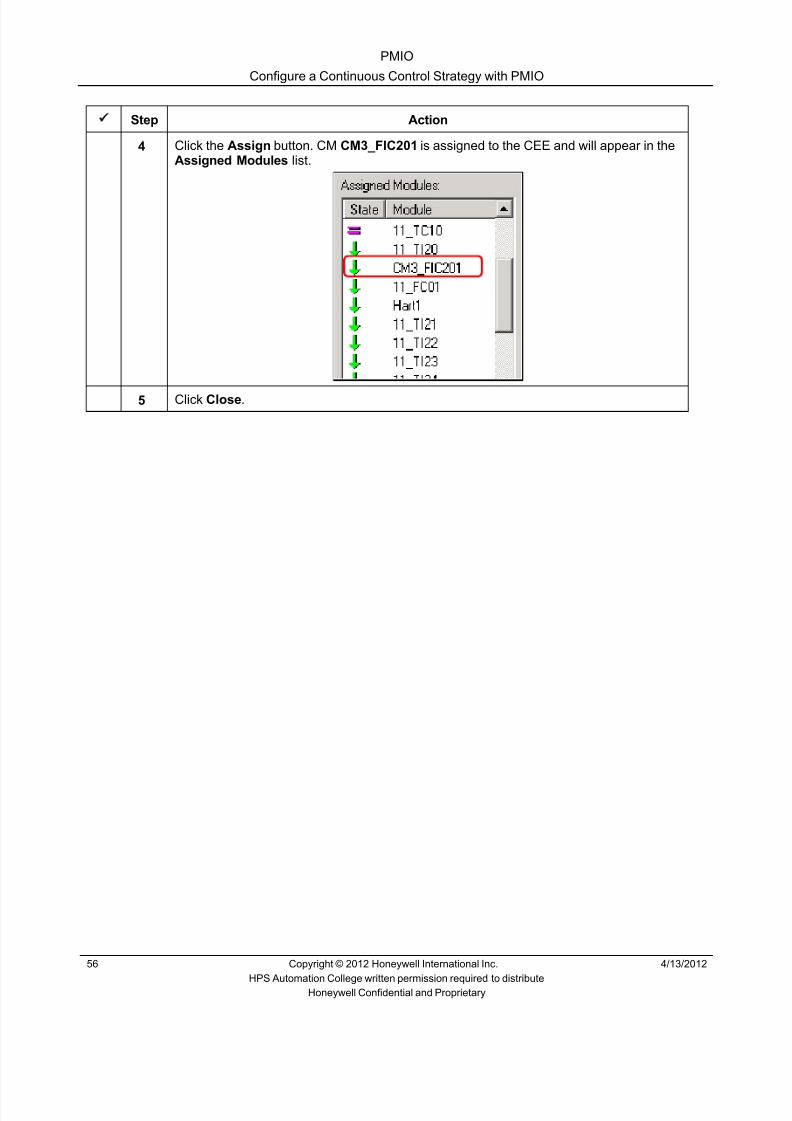
8/9/2019 Student Course Book- Automation
http://slidepdf.com/reader/full/student-course-book-automation 1036/1165
PMIO
Configure a Continuous Control Strategy with PMIO
56 Copyright © 2012 Honeywell International Inc. 4/13/2012
HPS Automation College written permission required to distributeHoneywell Confidential and Proprietary
Step Action
4 Click the Assign button. CM CM3_FIC201 is assigned to the CEE and will appear in theAssigned Modules list.
5 Click Close .

8/9/2019 Student Course Book- Automation
http://slidepdf.com/reader/full/student-course-book-automation 1037/1165
PMIO
Configure a Continuous Control Strategy with PMIO
4/13/2012 Copyright © 2012 Honeywell International Inc. 57
HPS Automation College written permission required to distributeHoneywell Confidential and Proprietary
Add Function Blocks to a CM
Step Action
1 Double-click the CM (CM3_FIC201) in the Project Tab to open the CM chart.
ATTENTION
You can add PMIO function blocks to a CM in twoways:
1 The Project Tree method.
2 The Library Tree method.
We will use the Project Tree method. This methoduses the fact that PMIO modules contain their ownconfiguration databases. Therefore when you add anIOP, its configuration parameters are available fromProject.
In this case, select the first AI channel from your HLAIIOP.
2 Expand the IOLIM0303 and IOLINK0303 and Click the + next to CPM3AI_F3C01 inproject to see the I/O Channels of CPM3AI_F3C01 IOP.
ATTENTION
If you are using SIM-C300 / C300 , then ExpandSIM_C300 PMIO_IOLINK

8/9/2019 Student Course Book- Automation
http://slidepdf.com/reader/full/student-course-book-automation 1038/1165
PMIO
Configure a Continuous Control Strategy with PMIO
58 Copyright © 2012 Honeywell International Inc. 4/13/2012
HPS Automation College written permission required to distributeHoneywell Confidential and Proprietary
Step Action
3 Click the block named AICHANNEL_01 and drag it into the CM (CM3_FIC201).
ATTENTION
When adding blocks from Project, the IO Channelblock is already assigned to an IOP and channel.
4 Drag the following blocks from the Library into your CM:
Block Family BlockDATAACQ DATAACQREGCTL PID
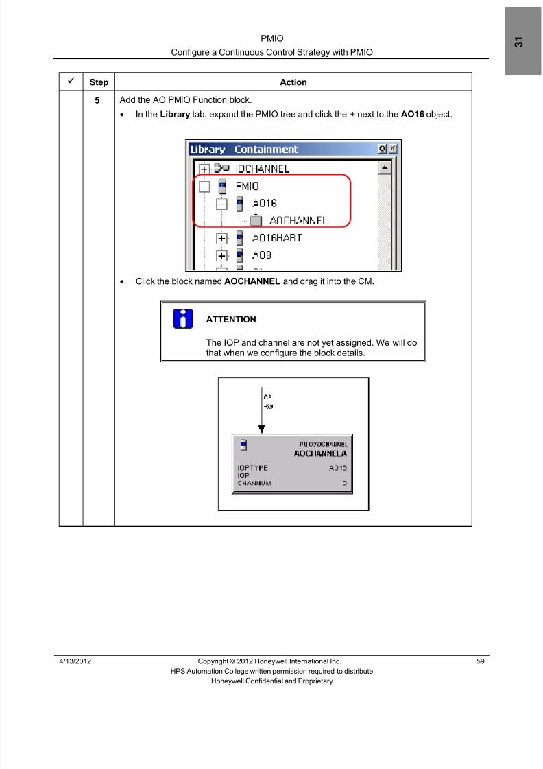
8/9/2019 Student Course Book- Automation
http://slidepdf.com/reader/full/student-course-book-automation 1039/1165
PMIO
Configure a Continuous Control Strategy with PMIO
4/13/2012 Copyright © 2012 Honeywell International Inc. 59
HPS Automation College written permission required to distributeHoneywell Confidential and Proprietary
Step Action
5 Add the AO PMIO Function block.• In the Library tab, expand the PMIO tree and click the + next to the AO16 object.
• Click the block named AOCHANNEL and drag it into the CM.
ATTENTION
The IOP and channel are not yet assigned. We will dothat when we configure the block details.

8/9/2019 Student Course Book- Automation
http://slidepdf.com/reader/full/student-course-book-automation 1040/1165
PMIO
Configure a Continuous Control Strategy with PMIO
60 Copyright © 2012 Honeywell International Inc. 4/13/2012
HPS Automation College written permission required to distributeHoneywell Confidential and Proprietary
Step Action
6 Arrange your blocks on the screen as shown below.

8/9/2019 Student Course Book- Automation
http://slidepdf.com/reader/full/student-course-book-automation 1041/1165
PMIO
Configure a Continuous Control Strategy with PMIO
4/13/2012 Copyright © 2012 Honeywell International Inc. 61
HPS Automation College written permission required to distributeHoneywell Confidential and Proprietary
Configure a PMIO AI Channel Block
Step Action
1 Double-click the PMIO AICHANNEL block.
2 Enter following details:
Name : AI0101
Associated IOP : CPM3AI_FC301 (This is already assigned, Please see below.)
Associated IOP Type : HLAI
ATTENTION
The Associated IOP and Channel Number are alreadyassigned. Since this block was added from the chosenHLAI IOP in the Project tab, it is already assigned tothe IOP and channel. When the block is renamed, thechannel takes on the same name in the IOP tree.

8/9/2019 Student Course Book- Automation
http://slidepdf.com/reader/full/student-course-book-automation 1042/1165
PMIO
Configure a Continuous Control Strategy with PMIO
62 Copyright © 2012 Honeywell International Inc. 4/13/2012
HPS Automation College written permission required to distributeHoneywell Confidential and Proprietary
Step Action
3 Click on the Configuration tab and enter following details:
PV Extended High Range: 5050
PV High Range : 5000
PV Low Range: 0
PV Extended Low Range: -50
Low Cutoff Signal: NaN
Accept all other values as default.
ATTENTION
The configuration of a PMIO AI channel differs fromthat of Series A IO. With Series A IO all configurationparameters reside in the C200E database. PMIOparameters are split between the IOPs and theirassociated IOLIM. The IOLIM communicatesparameter information to the associated C200E.
Each PMIO channel has a set of configurable
parameters and execution states. The parameters fora HLAI analog input block are shown here.
4 Click OK .

8/9/2019 Student Course Book- Automation
http://slidepdf.com/reader/full/student-course-book-automation 1043/1165
PMIO
Configure a Continuous Control Strategy with PMIO
4/13/2012 Copyright © 2012 Honeywell International Inc. 63
HPS Automation College written permission required to distributeHoneywell Confidential and Proprietary
Configure a Data Acquisition Block
Step Action
1 Double click the DATAACQ block.
2 Enter the following information:
Name : DACA
ATTENTION
This block must be named DACA in order for theExperion PKS supplied PID point detail display tofunction properly.
3 Enter the following additional information present on the Main tab:
Engr Units M3/Sec
Execution Order in CM 20
PVEU Range Hi 5000
PVEU Range Lo 0
PV Extended Limits Hi 5050
PV Extended Limits Lo -50
Low Signal Cut Off 0
PV Character None
Clamping Option: Enable
4 Click the Alarms tab.
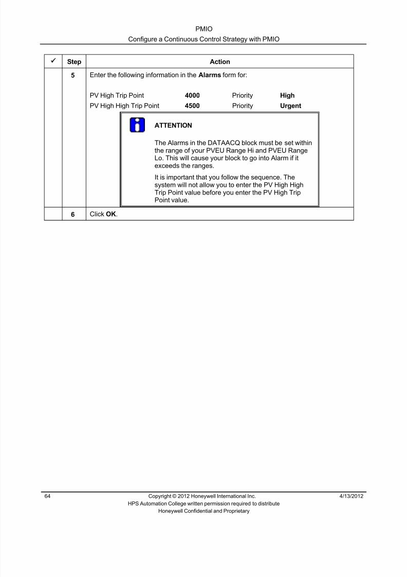
8/9/2019 Student Course Book- Automation
http://slidepdf.com/reader/full/student-course-book-automation 1044/1165
PMIO
Configure a Continuous Control Strategy with PMIO
64 Copyright © 2012 Honeywell International Inc. 4/13/2012
HPS Automation College written permission required to distributeHoneywell Confidential and Proprietary
Step Action
5 Enter the following information in the Alarms form for:
PV High Trip Point 4000 Priority High
PV High High Trip Point 4500 Priority Urgent
ATTENTION
The Alarms in the DATAACQ block must be set withinthe range of your PVEU Range Hi and PVEU RangeLo. This will cause your block to go into Alarm if itexceeds the ranges.
It is important that you follow the sequence. Thesystem will not allow you to enter the PV High HighTrip Point value before you enter the PV High Trip
Point value.6 Click OK .

8/9/2019 Student Course Book- Automation
http://slidepdf.com/reader/full/student-course-book-automation 1045/1165
PMIO
Configure a Continuous Control Strategy with PMIO
4/13/2012 Copyright © 2012 Honeywell International Inc. 65
HPS Automation College written permission required to distributeHoneywell Confidential and Proprietary
Configure a PID Block
Step Action
1 Double-click the PID block.2 Enter the following information:
Name PIDAEngineering Units M3/SecExecution Order 30PVEU Range Hi 5000PVEU Range Lo 0
ATTENTION
It is important that you name this block PIDA . If you donot name the block PIDA, you will not be able to seemany parameters from the Station Detail Displays.
3 Click the Algorithm tab.

8/9/2019 Student Course Book- Automation
http://slidepdf.com/reader/full/student-course-book-automation 1046/1165
PMIO
Configure a Continuous Control Strategy with PMIO
66 Copyright © 2012 Honeywell International Inc. 4/13/2012
HPS Automation College written permission required to distributeHoneywell Confidential and Proprietary
Step Action
4 Enter the following algorithm information:
T1 0.1T1 High Limit 2.0High Gain Limit 2.0Linear Gain LINOverall Gain .5
5 Click the Alarms Tab.
6 Enter the following information in the Alarms form for OP High (OPHIALM.TP):
Trip Point 95Priority LowSeverity 0
7 Click the SetPoint Tab.
8 Enter the following information for the Input Range:
High Limit 5000Low Limit 0
9 Click the Block Pins tab in the Configuration form.

8/9/2019 Student Course Book- Automation
http://slidepdf.com/reader/full/student-course-book-automation 1047/1165
PMIO
Configure a Continuous Control Strategy with PMIO
4/13/2012 Copyright © 2012 Honeywell International Inc. 67
HPS Automation College written permission required to distributeHoneywell Confidential and Proprietary
Step Action
10 Select Location for the PV pin to be at left .
TIP
To make the routing of the soft wiring from the DACAblock to the PIDA block more direct and neat, movethe PV input from the top of the PIDA block to the left.This will not improve performance, just clean up thewiring.
11 Click OK to close the PID parameter configuration form.
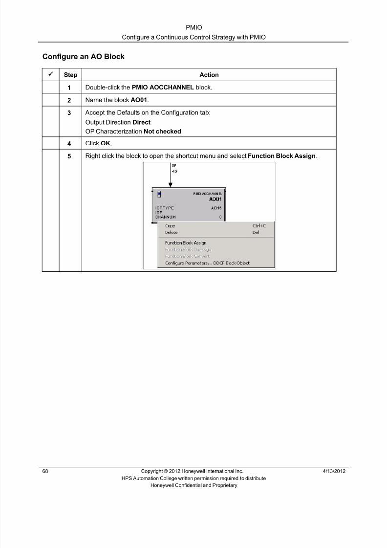
8/9/2019 Student Course Book- Automation
http://slidepdf.com/reader/full/student-course-book-automation 1048/1165
PMIO
Configure a Continuous Control Strategy with PMIO
68 Copyright © 2012 Honeywell International Inc. 4/13/2012
HPS Automation College written permission required to distributeHoneywell Confidential and Proprietary
Configure an AO Block
Step Action
1 Double-click the PMIO AOCCHANNEL block.
2 Name the block AO01 .
3 Accept the Defaults on the Configuration tab:
Output Direction Direct
OP Characterization Not checked
4 Click OK .
5 Right click the block to open the shortcut menu and select Function Block Assign .

8/9/2019 Student Course Book- Automation
http://slidepdf.com/reader/full/student-course-book-automation 1049/1165
PMIO
Configure a Continuous Control Strategy with PMIO
4/13/2012 Copyright © 2012 Honeywell International Inc. 69
HPS Automation College written permission required to distributeHoneywell Confidential and Proprietary
Step Action
6 In the Function Block Assignment Dialog :
1 Select Channel 1 of your assigned AO16 module.2 Click Assign
ATTENTION
The Function Block Assignment Dialog shows all channels ofall IOPs in the Project of the type selected. That is why thenames of the IOP modules need to be descriptive. Use thescroll bar to see the channel choices.
7 The AO block is now assigned to an IOP and Channel number.

8/9/2019 Student Course Book- Automation
http://slidepdf.com/reader/full/student-course-book-automation 1050/1165
PMIO
Configure a Continuous Control Strategy with PMIO
70 Copyright © 2012 Honeywell International Inc. 4/13/2012
HPS Automation College written permission required to distributeHoneywell Confidential and Proprietary
Step Action
8 Wire the blocks together as shown.
9 Save and close your CM.

8/9/2019 Student Course Book- Automation
http://slidepdf.com/reader/full/student-course-book-automation 1051/1165
PMIO
Configure a Continuous Control Strategy with PMIO
4/13/2012 Copyright © 2012 Honeywell International Inc. 71
HPS Automation College written permission required to distributeHoneywell Confidential and Proprietary
Configure a Hart Temperature Transmitter
Step Action
1 Add and assign a new Control Module to your CEE.Open the parameters Main tab and configure as below.
In Server Displays Tab
Point Detail Display: sysDtlDACA
Group Detail Display: sysGrpDACA
Group#: 61
Pos# : 2
Group Parameter: Hart1
Click OK .

8/9/2019 Student Course Book- Automation
http://slidepdf.com/reader/full/student-course-book-automation 1052/1165
PMIO
Configure a Continuous Control Strategy with PMIO
72 Copyright © 2012 Honeywell International Inc. 4/13/2012
HPS Automation College written permission required to distributeHoneywell Confidential and Proprietary
Step Action
2 Open Hart1 in chart view.
Expand the IOLIM0303 tree and browse to HART AI IO (CPM3HAI_F3C11) in the projecttree.
Drag Channel 01 onto the Hart1 chart.
`
ATTENTION
If you are using SIM-C300 / C300 , then expand thePMIO_IOLINK
3 Double click and open the HAICHANNEL_01 block properties window.
Select the HART Configuration tab and enable HART.

8/9/2019 Student Course Book- Automation
http://slidepdf.com/reader/full/student-course-book-automation 1053/1165
PMIO
Configure a Continuous Control Strategy with PMIO
4/13/2012 Copyright © 2012 Honeywell International Inc. 73
HPS Automation College written permission required to distributeHoneywell Confidential and Proprietary
Step Action
4 Select the Main Tab.
Change the name of HAICHANNEL_01 to HAI.
Click OK to close block properties for HAI.
5 Add a DATAACQ function block from the library .
Change the name of DATAACQ to DACA .
Close the properties windows for DACA block.
Wire the blocks as shown below.
6 Save and close the CM.

8/9/2019 Student Course Book- Automation
http://slidepdf.com/reader/full/student-course-book-automation 1054/1165
PMIO
Configure a Continuous Control Strategy with PMIO
74 Copyright © 2012 Honeywell International Inc. 4/13/2012
HPS Automation College written permission required to distributeHoneywell Confidential and Proprietary
This page was intentionally left blank.
8/9/2019 Student Course Book- Automation
http://slidepdf.com/reader/full/student-course-book-automation 1055/1165
PMIO
Load, Activate, and Operate CMs with PMIO
4/13/2012 Copyright © 2012 Honeywell International Inc. 75
HPS Automation College written permission required to distributeHoneywell Confidential and Proprietary
Load, Activate, and Operate CMs with PMIO
(This Lab is Optional)
Practice
Objective
After you complete this lesson, you will be able to activate CMs with PMIO channels and contrastthe activation to that of CMs using Series A and Series C IO.
• Download a CM with PMIO channels
• Activate a CM with PMIO channels
• Activate and deactivate PMIO channels
IntroductionThe purpose of this lesson is to give the knowledge to load and activate CMs that use PMIOchannels.
• Load CMs
• Activate CMs and IOP Channels
Note:
If you are using SIM_C300 / C300, then assignment of CM or IOP has to be done to CEE of SIM-C300 / C300
IOLIM0303 and IOLINK0303 (Referred in this lab) will not be present if you are using SIM-C300 /C300. Use PMIO_IOLINK to access the IOP

8/9/2019 Student Course Book- Automation
http://slidepdf.com/reader/full/student-course-book-automation 1056/1165
PMIO
Load, Activate, and Operate CMs with PMIO
76 Copyright © 2012 Honeywell International Inc. 4/13/2012
HPS Automation College written permission required to distributeHoneywell Confidential and Proprietary
Procedure
Load CMs
Step Action
1 Read the important information in the Attention box:
ATTENTION
This portion of the lab should be completed by ALLstudents – those configuring a C200E, and also thoseconfiguring a C300.
2 Select CM3_FIC201 and Hart1 Control Modules from the Project tab and click the Loadbutton.

8/9/2019 Student Course Book- Automation
http://slidepdf.com/reader/full/student-course-book-automation 1057/1165
PMIO
Load, Activate, and Operate CMs with PMIO
4/13/2012 Copyright © 2012 Honeywell International Inc. 77
HPS Automation College written permission required to distributeHoneywell Confidential and Proprietary
Step Action
3 Click Continue and verify the items to be loaded.
ATTENTION
The PMIO channel blocks are listed in the Load Dialogbox as separate entries with their own Post LoadStates.

8/9/2019 Student Course Book- Automation
http://slidepdf.com/reader/full/student-course-book-automation 1058/1165
PMIO
Load, Activate, and Operate CMs with PMIO
78 Copyright © 2012 Honeywell International Inc. 4/13/2012
HPS Automation College written permission required to distributeHoneywell Confidential and Proprietary
Step Action
4 Do NOT select the automatic Post Load State check box.
ATTENTION
IOPs have their own databases. Each channel hascapability beyond merely dealing with raw inputs andoutputs. One feature of a channel is its ability to beactive or inactive. Although both the CM and Channelscan be made active from the Automatically Changecheckbox, we will activate the blocks after loading tolearn from the process.
5 Click OK.
6 The Load dialog box will appear.
ATTENTION
The Load dialog box will automatically disappear thenthe load is complete with no errors.

8/9/2019 Student Course Book- Automation
http://slidepdf.com/reader/full/student-course-book-automation 1059/1165
PMIO
Load, Activate, and Operate CMs with PMIO
4/13/2012 Copyright © 2012 Honeywell International Inc. 79
HPS Automation College written permission required to distributeHoneywell Confidential and Proprietary
Activating CMs and IOP Channels
Step Action
1 After successfully loading the CM, go to the Monitoring tab.
2 Expand your CPM , CEE , and CMs in the tree.
3 Expand your IOLIM and IOLINK and your IOPs .
ATTENTION
Both the CMs and the IOP channel blocks are blue.The blue channel blocks appear both under the CMand under the IOPs.
The execution status is the same in both locations,and can be changed from either location.
If you are using SIM C300 / C300 , expand thePMIO_IOLINK and the IOP

8/9/2019 Student Course Book- Automation
http://slidepdf.com/reader/full/student-course-book-automation 1060/1165
PMIO
Load, Activate, and Operate CMs with PMIO
80 Copyright © 2012 Honeywell International Inc. 4/13/2012
HPS Automation College written permission required to distributeHoneywell Confidential and Proprietary
Step Action
4 To activate from the CM, select Hart1 and CM3_FIC201 and activate the CMs as shown.
ATTENTION
Activate the IOP Channel Blocks from either the CM orthe IOPs.
To Activate one Channel Block, right click the blockfrom under either the CM or under the IOP and selectActivate > Selected Item(s) and Content(s) .
5 Click Yes in the ‘Change State’ dialog box.

8/9/2019 Student Course Book- Automation
http://slidepdf.com/reader/full/student-course-book-automation 1061/1165
PMIO
Load, Activate, and Operate CMs with PMIO
4/13/2012 Copyright © 2012 Honeywell International Inc. 81
HPS Automation College written permission required to distributeHoneywell Confidential and Proprietary
Step Action
6
ATTENTION
The IO Channel Blocks turn green (Active) under boththe CM and the IOP tree locations
IOP location is different for SIM-C300 / C300 ( inPMIO_IOLINK)
7 NOTE: PMIO and Hart devices do not support the ability to use simulated values asinputs, as does C200E I/O.

8/9/2019 Student Course Book- Automation
http://slidepdf.com/reader/full/student-course-book-automation 1062/1165
PMIO
Load, Activate, and Operate CMs with PMIO
82 Copyright © 2012 Honeywell International Inc. 4/13/2012
HPS Automation College written permission required to distributeHoneywell Confidential and Proprietary
This page was intentionally left blank.

8/9/2019 Student Course Book- Automation
http://slidepdf.com/reader/full/student-course-book-automation 1063/1165
1
1
Honeywell ConfidentialCopyright © 2012 Honeywell International Inc.
4/13/2012
Describe Types of PID Control Blocks
Appendix Describe Types of PID Control BlocksAppendix Describe Types of PID Control Blocks
Honeywell
Honeywell ConfidentialCopyright © 2012 Honeywell International Inc.
4/13/20122
Overview
• In this presentation we will learn types of PID Blocks:
– Proportional, Integral & Derivative (PID)
– Proportional, Integral & Derivative with External Reset Feedback (PIDER)
– Proportional, Integral & Derivative with Feed forward (PIDFF)
– Proportional, Integral & Derivative with Profit Loop PKS (PID_PL)
Appendix Describe Types of PID Control Blocks

8/9/2019 Student Course Book- Automation
http://slidepdf.com/reader/full/student-course-book-automation 1064/1165
2
Honeywell
Honeywell ConfidentialCopyright © 2012 Honeywell International Inc.
4/13/20123
Overview
• PID Blocks – Are regulatory control blocks that operate as a proportional-integral-
derivative (PID) controller
– Support the Ideal form of calculating the PID terms
– Ideal form is often called the digital-computer version of the PID controller
Appendix Describe Types of PID Control Blocks
Honeywell
Honeywell ConfidentialCopyright © 2012 Honeywell International Inc.
4/13/20124
PID
• PID – Provides an implementation of the PID algorithm using the Ideal form,
whereby the following combinations of control terms may be configured: – Proportional-only (acts on the error PV - SP) – Integral-only (acts on the error PV - SP) – Proportional & integral (act on error PV - SP), & derivative (acts on changes
in PV) – Proportional & derivative (act on changes in PV), & integral (acts on the error
PV - SP) – Proportional, integral & derivative (act on the error PV - SP)
Appendix Describe Types of PID Control Blocks

8/9/2019 Student Course Book- Automation
http://slidepdf.com/reader/full/student-course-book-automation 1065/1165
3
Honeywell
Honeywell ConfidentialCopyright © 2012 Honeywell International Inc.
4/13/20125
PIDER
• PIDER – Operates as a proportional-integral-derivative (PID) controller that accepts a
reset feedback signal, a tracking value, and a tracking control switch – Supports the same Ideal form of calculating the PID terms as the PID block – Also prevents windup when the secondary does not propagate windup
status or control initialization data back to the primary of a remote (foreign)controller
Appendix Describe Types of PID Control Blocks
Honeywell
Honeywell ConfidentialCopyright © 2012 Honeywell International Inc.
4/13/20126
PIDFF
• PIDFF – Provides the same classic PID function as outlined above with the ability to
accept a “feed forward” signal – Can configure the feed forward signal to be added to or multiplied by the
PID’s incremental output to meet varying control requirements
Appendix Describe Types of PID Control Blocks

8/9/2019 Student Course Book- Automation
http://slidepdf.com/reader/full/student-course-book-automation 1066/1165
4
Honeywell
Honeywell ConfidentialCopyright © 2012 Honeywell International Inc.
4/13/20127
PID_PL
• PID_PL – Provides PID control using a model predictive control package called Profit
Loop PKS – Incorporates robust control techniques to enhance control performance
despite process model uncertainty and measurement error
Appendix Describe Types of PID Control Blocks
Honeywell
Honeywell ConfidentialCopyright © 2012 Honeywell International Inc.
4/13/20128
PID
• The PID block has two analog inputs – a process variable (PV) and a setpoint (SP) – The difference between PV and SP is the error, and the PID block calculates
a control output (OP) that drives the error to zero
• The following equations are supported: – Proportional, Integral, and Derivative (PID) on the error – Proportional and Integral (PI) on the error and Derivative (D) on changes in
PV – Integral (I) on the error and Proportional and Derivative (PD) on changes in
PV – Integral (I) only
– Proportional (P) only
Appendix Describe Types of PID Control Blocks

8/9/2019 Student Course Book- Automation
http://slidepdf.com/reader/full/student-course-book-automation 1067/1165
5
Honeywell
Honeywell ConfidentialCopyright © 2012 Honeywell International Inc.
4/13/20129
PID Main Tab
• The Main Tab is for configuring the name, process value, and mode
Allow to set thePV values
Explained Later
Specifies the executionorder of the block in the
CM relative to other blockscontained in this CM
Explainedlater
Appendix Describe Types of PID Control Blocks
Honeywell
Honeywell ConfidentialCopyright © 2012 Honeywell International Inc.
4/13/201210
Manual PV Option
• Used to specify the mode and output the block is toassume when PV status (PVSTS) changes to MANUAL
• The following options are available – NOSHED - No changes
– SHEDHOLD - Sets MODE to MANUAL and MODEATTR to Operator, disablesexternal mode switching (ESWPERM), and holds output at the last good value
– SHEDLOW - Sets MODE to MANUAL and MODEATTR to Operator, disables externalmode switching (ESWPERM), and sets output to its extended low limit OPEXLOLM)value
– SHEDHIGH - Sets MODE to MANUAL and MODEATTR to Operator, disablesexternal mode switching (ESWPERM), and sets output to its extended high limit
OPEXHILM) value
– SHEDSAFE - Sets MODE to MANUAL and MODEATTR to Operator, disablesexternal mode switching (ESWPERM), and sets output to the configured safe outputSAFEOP) value
Appendix Describe Types of PID Control Blocks

8/9/2019 Student Course Book- Automation
http://slidepdf.com/reader/full/student-course-book-automation 1068/1165
6
Honeywell
Honeywell ConfidentialCopyright © 2012 Honeywell International Inc.
4/13/201211
Safety Interlock and Bad Control Option
• Safety Interlock Option – Specifies the value of MODE and OP which the block is to assume upon a
safety interlock alarm
• Bad Control Option – Specifies the value of MODE and OP which the block is to assume if CV
goes BAD
• Both the parameters have the same options
• The explanation for each parameter value wasprovided in previous slides
Appendix Describe Types of PID Control Blocks
Honeywell
Honeywell ConfidentialCopyright © 2012 Honeywell International Inc.
4/13/201212
PID Main Tab
Identifies the Analog Input Channel block to readPVRAW. The faceplate display shows the block’sPVRAW from this input source in comparison withthe PV
Applicable only for Cascade loops. Block accepts orignores the initialization and override requests fromthe secondary based on this selection . The defaultselection is Enabled (checked or accepts requests).
Appendix Describe Types of PID Control Blocks

8/9/2019 Student Course Book- Automation
http://slidepdf.com/reader/full/student-course-book-automation 1069/1165
7
Honeywell
Honeywell ConfidentialCopyright © 2012 Honeywell International Inc.
4/13/201213
Mode• Mode identifies who may store values to the block's initializable inputs or output
• MODE processing checks for the following conditions and changes the block's MODE asappropriate – External request for MODE switching
– Safety interlock request
• Configuration options available are:
– NONE - No Mode configured
– MAN - OP is stored by either the operator or a user program
– AUTO - The function block derives OP. The input is stored by either the operator or an userprogram
– CAS – The block fetches its initializable input from the primary and calculates OP
– BCAS – The function block derives OP. The input is pulled from another function block (theprimary)
– NORMAL - Parameter NORMMODE value is used
Appendix Describe Types of PID Control Blocks
Honeywell
Honeywell ConfidentialCopyright © 2012 Honeywell International Inc.
4/13/201214
Mode Attribute
• Mode Attribute identifies who may store values to the output (OP) whenthe block's MODE is Manual
• Configuration options available are:
– NONE - Mode Attribute is not configured
– OPERATOR - Operator can set MODE, OP, SP, RATIO and BIAS
– PROGRAM - Program can set MODE, OP, SP, RATIO and BIAS
Appendix Describe Types of PID Control Blocks

8/9/2019 Student Course Book- Automation
http://slidepdf.com/reader/full/student-course-book-automation 1070/1165
8
Honeywell
Honeywell ConfidentialCopyright © 2012 Honeywell International Inc.
4/13/201215
Normal Mode
• Normal Mode is the MODE that the block is to assume when theControl to Normal function is initiated through the Stationdisplay
• When the MODE option is set to NORMAL, the block chooses the modefrom this parameter
• Configuration options available are similar to MODE
Appendix Describe Types of PID Control Blocks
Honeywell
Honeywell ConfidentialCopyright © 2012 Honeywell International Inc.
4/13/201216
Normal Mode Attribute
• Normal Mode Attribute is the Mode Attribute (MODEATTR) theblock is to assume when the Control to Normal function isinitiated through the Station display
• Configuration options available are:
– NONE - Normal Mode Attribute is not configured
– OPERATOR - Operator stores to OP or SP as determined by MODE.Operator also store to MODE
– PROGRAM - A program stores to OP or SP as determined by MODE.Program also store to MODE.
Appendix Describe Types of PID Control Blocks
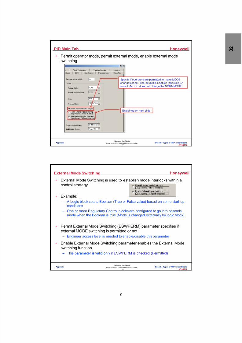
8/9/2019 Student Course Book- Automation
http://slidepdf.com/reader/full/student-course-book-automation 1071/1165
9
Honeywell
Honeywell ConfidentialCopyright © 2012 Honeywell International Inc.
4/13/201217
PID Main Tab
• Permit operator mode, permit external mode, enable external modeswitching
Specify if operators are permitted to make MODEchanges or not. The default is Enabled (checked). Astore to MODE does not change the NORMMODE
Explained on next slide
Appendix Describe Types of PID Control Blocks
Honeywell
Honeywell ConfidentialCopyright © 2012 Honeywell International Inc.
4/13/201218
External Mode Switching
• External Mode Switching is used to establish mode interlocks within acontrol strategy
• Example: – A Logic block sets a Boolean (True or False value) based on some start-up
conditions – One or more Regulatory Control blocks are configured to go into cascade
mode when the Boolean is true (Mode is changed externally by logic block)
• Permit External Mode Switching (ESWPERM) parameter specifies ifexternal MODE switching is permitted or not – Engineer access level is needed to enable/disable this parameter
• Enable External Mode Switching parameter enables the External Modeswitching function – This parameter is valid only if ESWPERM is checked (Permitted)
Appendix Describe Types of PID Control Blocks

8/9/2019 Student Course Book- Automation
http://slidepdf.com/reader/full/student-course-book-automation 1072/1165
10
Honeywell
Honeywell ConfidentialCopyright © 2012 Honeywell International Inc.
4/13/201219
Enable Bad Output Connection Option
• Enable Bad Output Connection Option is a checkbox selection optionavailable in all regulatory control blocks – By default disabled,
• To enable BADOCOPT, enable the option BADOCOPTENB
• If enabled, user can configure the delay value in BADOCOPT parameter – Mode is forced to MANUAL after a specified delay on loss of I/O
communication
Enter Bad Output ConnectionOption between 0 to 60
Appendix Describe Types of PID Control Blocks
Honeywell
Honeywell ConfidentialCopyright © 2012 Honeywell International Inc.
4/13/201220
Algorithm Tab
Used to select the controlequation. The selections areEQA, EQB, EQC, EQD, andEQE. Explained in next slide
Explained later in presentation
Specifies the Integral timeused in the Control equation
Used to set the gain limits
Specifies the High and Lowlimit values for the Integraltime setting
Specifies the Derivative timeused in the Control equation
Specifies the High and Lowlimit values for the Derivativetime setting
Appendix Describe Types of PID Control Blocks

8/9/2019 Student Course Book- Automation
http://slidepdf.com/reader/full/student-course-book-automation 1073/1165

8/9/2019 Student Course Book- Automation
http://slidepdf.com/reader/full/student-course-book-automation 1074/1165
12
Honeywell
Honeywell ConfidentialCopyright © 2012 Honeywell International Inc.
4/13/201223
Algorithm Tab
• Non Linear gain (NONLIN) option provides a proportional control action
that is equal to the square of the error – Applies to equations A, B, and C
– Non-Linearity Form (NLFORM) specifies thevalue (0 or 1) to be used for calculating gain (K)
• Default value is 1
– Non-Linear Gain Factor (NLGAIN) specifies the non-linear gain value to beused for calculating gain (K)
• Default value is 0
• Legacy Gap - Allows the user to revert back to old GAP and Nonlineargain calculations so that there is no change in behavior after migration
from TPS to Experion – When enabled, it will allow the Experion controllers to have the samebehavior as the TPS xPM controller
Appendix Describe Types of PID Control Blocks
Honeywell
Honeywell ConfidentialCopyright © 2012 Honeywell International Inc.
4/13/201224
Algorithm Tab
• External gain (EXT) option modifies the gain (K) by an input value fromeither the process, another function block, or a user program – Used to compensate for nonlinear process gain – Lets you tune the PID gain independent of the normal operating point of the
process – Eg: For controlling the level of tank whose cross-section is not constant, the
EXT option can be used to modify the gain to compensate for the nonlinearrate of level change, which is caused by the changing shape of the tank
• Applies to equations A, B, and C
• External Gain Factor (KMODIFEXT) specifies an input value from either
the process, another function block, or a user program to be used tomodify the gain (K) calculation per this equation:K = KLIN * KMODIFEXT
Appendix Describe Types of PID Control Blocks

8/9/2019 Student Course Book- Automation
http://slidepdf.com/reader/full/student-course-book-automation 1075/1165
13
Honeywell
Honeywell ConfidentialCopyright © 2012 Honeywell International Inc.
4/13/201225
• The PID block provides five different equations for calculating the PID – The CTLEQN parameter is used to specify the desired equation
• Equation A: – All three terms (Proportional, Integral, Derivative) act on the error (PV - SP)
as shown
• Equation B: – The proportional and integral terms act on the error (PV - SP) and the
derivative term acts on changes in PV
– This equation is used to eliminate derivative spikes in the control action as aresult of quick changes in SP
Algorithm Tab
Appendix Describe Types of PID Control Blocks
Honeywell
Honeywell ConfidentialCopyright © 2012 Honeywell International Inc.
4/13/201226
• Equation C: – The integral term acts on the error (PV - SP) and the proportional and
derivative terms act on changes in PV
– This equation provides the smoothest and slowest response to SP changes
• Equation D – Provides only Integral control
• Equation E – Provides only Proportional Control
• CV = K (PV - SP) + OPBIAS.FIX + OPBIAS.FLOAT• Equation E does not work with the override feedback function• It is a whole value algorithm that bumps the output to PV-SP regardless
of the ORFBVAL preset to CV
Algorithm Tab
Appendix Describe Types of PID Control Blocks

8/9/2019 Student Course Book- Automation
http://slidepdf.com/reader/full/student-course-book-automation 1076/1165
14
Honeywell
Honeywell ConfidentialCopyright © 2012 Honeywell International Inc.
4/13/201227
• Acronyms used in the Equations : – CV = output of PID (Equations A, B, C, D) in percent or output of P-controller
(Equation E only) in engineering units – K = gain (proportional term) – L-1 = inverse of the LaPlace transform – PV = process input value in engineering units – PVP = PV in percent – a = 1/16 fixed rate amplitude – s = La Place operator – SP = set point value in engineering units – SPP = SP in percent – T1 = integral time constant in minutes – T2 = derivative time constant in minutes – OPBIAS.FIX = fixed bias (Equation E only) – OPBIAS.FLOAT = floating bias (Equation E only)
Algorithm Tab
Appendix Describe Types of PID Control Blocks
Honeywell
Honeywell ConfidentialCopyright © 2012 Honeywell International Inc.
4/13/201228
Algorithm
• Direct or reverse control – A PID block is configured for direct-control action or reverse-control action – Changing the control action effectively changes the sign of the gain
• With direct-control action, an increase in the error (PV - SP) increasesthe PID output (CV)
• With reverse-control action, an increase in the error (PV - SP) decreasesthe PID output (CV)
– For example,• If SPP = 50% and PVP = 51%, then the error is 1%
– With direct-control action, if PVP changes to 52%, the error
increases causing CV to increase – With reverse-control action, if PVP changes to 52%, the errorincreases causing CV to decrease
Appendix Describe Types of PID Control Blocks
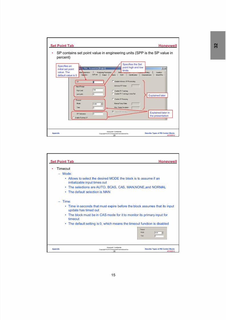
8/9/2019 Student Course Book- Automation
http://slidepdf.com/reader/full/student-course-book-automation 1077/1165
15
Honeywell
Honeywell ConfidentialCopyright © 2012 Honeywell International Inc.
4/13/201229
Set Point Tab
• SP contains set point value in engineering units (SPP is the SP value inpercent)
Specifies aninitial set pointvalue. Thedefault value is 0
Specifies the Setpoint high and lowlimits
Explained later inthe presentation
Explained later
Appendix Describe Types of PID Control Blocks
Honeywell
Honeywell ConfidentialCopyright © 2012 Honeywell International Inc.
4/13/201230
Set Point Tab
• Timeout – Mode:
• Allows to select the desired MODE the block is to assume if aninitializable input times out
• The selections are AUTO, BCAS, CAS, MAN,NONE,and NORMAL• The default selection is MAN
– Time:• Time in seconds that must expire before the block assumes that its input
update has timed out• The block must be in CAS mode for it to monitor its primary input for
timeout
• The default setting is 0, which means the timeout function is disabled
Appendix Describe Types of PID Control Blocks

8/9/2019 Student Course Book- Automation
http://slidepdf.com/reader/full/student-course-book-automation 1078/1165
16
Honeywell
Honeywell ConfidentialCopyright © 2012 Honeywell International Inc.
4/13/201231
Set Point Tab
• Enable SP Push: (PUSHSP) – Used for Cascade loops where the Primary and Secondary are in different
Experion clusters – When Selected, the SP for the Secondary PID block is pushed from the
Primary through an Inter Cluster Gateway – When this option is not selected the Secondary will pull the SP from the
primary
Appendix Describe Types of PID Control Blocks
Honeywell
Honeywell ConfidentialCopyright © 2012 Honeywell International Inc.
4/13/201232
Set Point Tab
• Enable Advisory SP Processing (ADVDEVOPT) – Generates a deviation alarm when the PV deviates from a user specified
“advisory” SP value – The default selection is unchecked (Disabled)
• Advisory SP Value (ADVSP) – Sets an advisory SP value in PV engineering units, when Advisory SP
Processing is enabled – When PV exceeds or deviates from this value, the block generates an
advisory deviation alarm
Appendix Describe Types of PID Control Blocks

8/9/2019 Student Course Book- Automation
http://slidepdf.com/reader/full/student-course-book-automation 1079/1165
17
Honeywell
Honeywell ConfidentialCopyright © 2012 Honeywell International Inc.
4/13/201233
Set Point Tab• Enable PV Tracking (PVTRAKOPT)
– Specifies if PV tracking is enabled for this block – When PV tracking is enabled, it sets the SP equal to PV when a cascade
loop is interrupted by either initialization, operator or program operation(setting MODE to MAN)
– Enabled for PIDs in a cascade loop – Default selection is unchecked (disabled)
• Enable PV Tracking in Auto/Init (PVTRAKOPTAI) – Specifies if PV Tracking option is enabled for the specific case when the
block is in Auto mode and it is undergoing initialization (INITMAN is ON) – The default selection is unchecked (disabled)
Appendix Describe Types of PID Control Blocks
Honeywell
Honeywell ConfidentialCopyright © 2012 Honeywell International Inc.
4/13/201234
Set Point Tab
• Enable SP Ramping (SPTVOPT) – Allow to specify if an operator can initiate a set point ramp action or not – It provides a smooth transition from the current set point value to a new one – The default selection is unchecked (disabled)
• Normal Ramp Rate (SPTVNORMRATE) – Specifies a ramp rate per minute in engineering units, when SP Ramping is
enabled – This starts the SP ramping function without specifying a ramp time – The default selection is Not a Number (NaN)
• Max. Ramp Deviation (SPTVDEVMAX) – Specifies the maximum Ramp deviation value per minute
in engineering units, when SP Ramping is enabled – Maintains the PV value within the specified deviation
range for a ramping SP• Stops the SP ramp until the PV input catches up
with the SP value
Appendix Describe Types of PID Control Blocks

8/9/2019 Student Course Book- Automation
http://slidepdf.com/reader/full/student-course-book-automation 1080/1165
18
Honeywell
Honeywell ConfidentialCopyright © 2012 Honeywell International Inc.
4/13/201235
Output Tab
• Output Indication (OUTIND) parameter specifies the way to access theoutput (OP) parameter and display them on the block’s faceplate display
• Following options are available – Direct – Reverse – DirectDisplnd – ReverseDisplnd
Appendix Describe Types of PID Control Blocks
Honeywell
Honeywell ConfidentialCopyright © 2012 Honeywell International Inc.
4/13/201236
Output Tab
• Direct – No value reversal - Output range is 0 to 100 percent – No display indications - Closed / Open indication is not shown on the OP bar graph of
the faceplate display – This is the default selection
• Reverse – Value reversal - Output range is 100 to 0 percent – No display indications - Closed / Open indication is not shown on the OP bar graph of
the faceplate display
• DirectDisplnd – No value reversal - output range is 0 to 100 percent – Closed and Open indications are shown at the 0 and 100 percent points on the OP
bar graph of the faceplate display
• ReverseDisplnd – No value reversal - output range is 0 to 100 percent – Closed and Open indications are shown at the 100 and 0 percent points on the OP
bar graph of the faceplate
Appendix Describe Types of PID Control Blocks

8/9/2019 Student Course Book- Automation
http://slidepdf.com/reader/full/student-course-book-automation 1081/1165
19
Honeywell
Honeywell ConfidentialCopyright © 2012 Honeywell International Inc.
4/13/201237
Output
• Valve indicator position shows a graphical indicator on the OP bargraphs of whether a valve is open at 0% or closed at 100% – If the valve is opened, it will be indicated by Hollow Valve – If it closed, it will be indicated as Filled Valve
Closing of valve in
Direct Direction
Closing of valve inReverse Direction
Appendix Describe Types of PID Control Blocks
Honeywell
Honeywell ConfidentialCopyright © 2012 Honeywell International Inc.
4/13/201238
Alarms Tab
• Set the alarm values for PID block
Type – Identifies the types ofalarms this block supports
Allow to enable or disable AdvisoryDeviation and/or Safety Interlock alarmtypes
Sets the trip points for the given alarm.The default value is NaN (Disables trippoint)
Assign a relative severityindividually for each alarmtype as a number between0 to 15, with 15 being themost severe
Appendix Describe Types of PID Control Blocks

8/9/2019 Student Course Book- Automation
http://slidepdf.com/reader/full/student-course-book-automation 1082/1165
20
Honeywell
Honeywell ConfidentialCopyright © 2012 Honeywell International Inc.
4/13/201239
Alarms Tab
Alarm is neither reported
nor annunciated
Alarm is logged but itdoes not appear on the
Alarm Summary display
Alarm is annunciatedand appears on the
Alarm Summary display
Specifies a dead band valuethat applies to all analog alarmsto prevent nuisance alarms dueto noise at values near the trippoint. Default value is 1
Specifies a time in seconds to define howlong an analog alarm must exist before it isset true. The default value is 0, which meansthe alarm is set true as soon as the valueexceeds the deadband value
Specifies the unit of deadbandvalue (Percent or EU
Appendix Describe Types of PID Control Blocks
Honeywell
Honeywell ConfidentialCopyright © 2012 Honeywell International Inc.
4/13/201240
SCM Tab
• SCM tab allows the configuration of Sequential Control Module (SCM)parameters for either block
Select an SCM Mode Tracking Option(MODETRACK) to identify when the operatorcan take over control of the device from theSequential Control Module (SCM)
Set the abnormal
state options forabnormal conditions
Appendix Describe Types of PID Control Blocks

8/9/2019 Student Course Book- Automation
http://slidepdf.com/reader/full/student-course-book-automation 1083/1165
21
Honeywell
Honeywell ConfidentialCopyright © 2012 Honeywell International Inc.
4/13/201241
SCM Tab
• MODETRACK is used by the device to determine the states ofMODEATTR and NORMMODEATTR based upon the MODE (that is,SCMMODE) of the containing CONTROLMODULE block
• Following MODETRACK options are available – ONESHOT – CONTRTN – SEMICONT – CONT
• ONESHOT – When SCMMODE is changed from Manual to Auto, SemiAuto or SingleStep
or when SCMSTATE changes from idle to Running:• MODEATTR is set to Program, but can also be changed by the operator
– When SCMMODE is changed back to Manual:• MODEATTR is returned to operator
Appendix Describe Types of PID Control Blocks
Honeywell
Honeywell ConfidentialCopyright © 2012 Honeywell International Inc.
4/13/201242
SCM Tab
• CONTRTN – When SCMMODE is changed from Manual to Auto, SemiAuto or SingleStep
or the SCMSTATE changes from idle to Running:• MODEATTR is set to Program and cannot be changed by the operator
as long as the SCM remains in automatic – When SCMMODE is changed back to Manual:
• MODEATTR is returned to operator
• SEMICONT – When SCMMODE is changed from Manual to Auto, SemiAuto or SingleStep
or the SCMSTATE changes from idle to Running or when any of theSCMSTEP(i) changes while SCMMODE is automatic:
• MODEATTR is set to Program, but can also be changed by the operator – When SCMMODE is changed back to Manual:
• MODEATTR is returned to operator
Appendix Describe Types of PID Control Blocks

8/9/2019 Student Course Book- Automation
http://slidepdf.com/reader/full/student-course-book-automation 1084/1165
22
Honeywell
Honeywell ConfidentialCopyright © 2012 Honeywell International Inc.
4/13/201243
SCM Tab
• CONT – When SCMMODE is changed from Manual to Auto, SemiAuto or SingleStep
• MODEATTR is set to Program and cannot be changed by the operatoras long as the SCM remains in Automatic
– When SCMMODE is changed back to Manual• MODEATTR is not changed, but the Operator can overwrite it
Appendix Describe Types of PID Control Blocks
Honeywell
Honeywell ConfidentialCopyright © 2012 Honeywell International Inc.
4/13/201244
SCM Tab
• Option Type – Allow to specify the action the function block is to take when the SCM goes
into an abnormal state
– The Starting State Option (STARTOPT)• Applies when the SCM state is Checking, Idle, or Complete
– The Stop/Abort State Option (STOPOPT)• Applies when the SCM state is Stopping or Stopped, Aborting or Aborted
– The Hold State Option (HOLDOPT)• Applies when the SCM state is Holding or Hold
– The Restart State Option (RESTARTOPT)• Applies when the SCM state is Resume or Run
– The NONE and LASTREQ• The only selections for the Restart State Option
Appendix Describe Types of PID Control Blocks

8/9/2019 Student Course Book- Automation
http://slidepdf.com/reader/full/student-course-book-automation 1085/1165
23
Honeywell
Honeywell ConfidentialCopyright © 2012 Honeywell International Inc.
4/13/201245
SCM Tab
• NONE - No changes• MAN - Set MODEREQ to MANUAL• AUTO - Set MODEREQ to AUTOMATIC• CAS - Set MODEREQ to CASCADE• FIXEDOP - Set OPREQ to the Configured Value• HOLDPV - Set SPREQ to PV• FIXED SP - Set SPREQ to the Configured Value and SPRATEREQ to
NaN• RAMPEDSP - Set SPTVREQ to the Configured Value and
SPRATEREQ to Configured Rate
Appendix Describe Types of PID Control Blocks
Honeywell
Honeywell ConfidentialCopyright © 2012 Honeywell International Inc.
4/13/201246
SCM Tab
• Value for (STARTVAL, STOPVAL, HOLDVAL) – Specifies an output or set point value within the respective range dependingupon Option Type selection
• For output, the range is between OPEXLOLM and OPEXHILM• For Set point the range is between SPLOLM and SPHILM
– The default value is NaN (Not a Number)
• Rate for (STARTRATE, STOPRATE, HOLDRATE) – Applicable only for RAMPEDSP option – Specifies a rate value (STARTRATE, STOPRATE, HOLDRATE) for setting
the SPRATEREQ of SP ramping function
Appendix Describe Types of PID Control Blocks
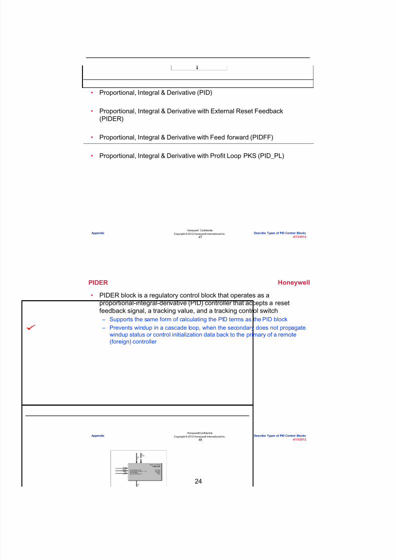
8/9/2019 Student Course Book- Automation
http://slidepdf.com/reader/full/student-course-book-automation 1086/1165
24
Honeywell
Honeywell ConfidentialCopyright © 2012 Honeywell International Inc.
4/13/201247
Topics
• Proportional, Integral & Derivative (PID)
• Proportional, Integral & Derivative with External Reset Feedback(PIDER)
• Proportional, Integral & Derivative with Feed forward (PIDFF)
• Proportional, Integral & Derivative with Profit Loop PKS (PID_PL)
Appendix Describe Types of PID Control Blocks
Honeywell
Honeywell ConfidentialCopyright © 2012 Honeywell International Inc.
4/13/201248
PIDER
• PIDER block is a regulatory control block that operates as aproportional-integral-derivative (PID) controller that accepts a resetfeedback signal, a tracking value, and a tracking control switch – Supports the same form of calculating the PID terms as the PID block – Prevents windup in a cascade loop, when the secondary does not propagate
windup status or control initialization data back to the primary of a remote(foreign) controller
Appendix Describe Types of PID Control Blocks

8/9/2019 Student Course Book- Automation
http://slidepdf.com/reader/full/student-course-book-automation 1087/1165
25
Honeywell
Honeywell ConfidentialCopyright © 2012 Honeywell International Inc.
4/13/201249
PIDER
• The PIDER block accepts five inputs – A process variable (PV), a set point (SP), a reset feedback value (RFB), a
tracking value (TRFB), and a tracking control switch (S1) – The reset feedback (RFB) signal comes from the remote controller’s PV, and
the tracking value (TRFB) comes from its PV or SP – By monitoring the remote controller’s PV and SP, the PIDER block can
determine if the remote controller is responding• If the remote controller is not responding, it can prevent its own output
from winding up
• The following equations are supported: – Proportional, Integral, and Derivative (PID) on the error (Equation A) – Proportional and Integral (PI) on the error and Derivative (D) on changes in
PV (Equation B)
– Integral (I) on the error and Proportional and Derivative (PD) on changes inPV (Equation C) – Integral (I) only (Equation D)
Appendix Describe Types of PID Control Blocks
Honeywell
Honeywell ConfidentialCopyright © 2012 Honeywell International Inc.
4/13/201250
PIDER
• All Tabs are similar to PID block• The option of Reset Feedback in algorithm tab is available for PIDER
The gain value to be appliedto the Reset Feedback signalas a scaling factor
The maximum deviation allowedbetween the calculated value (CV)and the RFB signal in percent
Appendix Describe Types of PID Control Blocks

8/9/2019 Student Course Book- Automation
http://slidepdf.com/reader/full/student-course-book-automation 1088/1165
26
Honeywell
Honeywell ConfidentialCopyright © 2012 Honeywell International Inc.
4/13/201251
Topics
• Proportional, Integral & Derivative (PID)
• Proportional, Integral & Derivative with External Reset Feedback(PIDER)
• Proportional, Integral & Derivative with Feed forward (PIDFF)
• Proportional, Integral & Derivative with Profit Loop PKS (PID_PL)
Appendix Describe Types of PID Control Blocks
Honeywell
Honeywell ConfidentialCopyright © 2012 Honeywell International Inc.
4/13/201252
PIDFF
• The PIDFF block is like the PID block but it accepts a feedforward signalas an additional input
– Can configure the PIDFF block so the feedforward signal is added to ormultiplied by the normal PID algorithm’s incremental output to meetparticular control requirements
– Can implement a feedforward control function through a single function block
Appendix Describe Types of PID Control Blocks
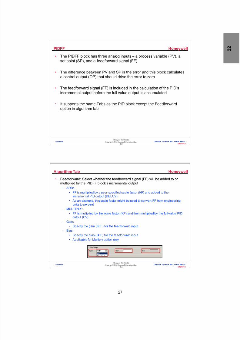
8/9/2019 Student Course Book- Automation
http://slidepdf.com/reader/full/student-course-book-automation 1089/1165
27
Honeywell
Honeywell ConfidentialCopyright © 2012 Honeywell International Inc.
4/13/201253
PIDFF
• The PIDFF block has three analog inputs – a process variable (PV), aset point (SP), and a feedforward signal (FF)
• The difference between PV and SP is the error and this block calculatesa control output (OP) that should drive the error to zero
• The feedforward signal (FF) is included in the calculation of the PID’sincremental output before the full value output is accumulated
• It supports the same Tabs as the PID block except the Feedforwardoption in algorithm tab
Appendix Describe Types of PID Control Blocks
Honeywell
Honeywell ConfidentialCopyright © 2012 Honeywell International Inc.
4/13/201254
Algorithm Tab
• Feedforward: Select whether the feedforward signal (FF) will be added to ormultiplied by the PIDFF block’s incremental output – ADD:-
• FF is multiplied by a user-specified scale factor (KF) and added to theincremental PID output (DELCV)
• As an example, this scale factor might be used to convert FF from engineeringunits to percent
– MULTIPLY:-• FF is multiplied by the scale factor (KF) and then multiplied by the full-value PID
output (CV) – Gain:-
• Specify the gain (KFF) for the feedforward input – Bias:-
• Specify the bias (BFF) for the feedforward input• Applicable for Multiply option only
Appendix Describe Types of PID Control Blocks
8/9/2019 Student Course Book- Automation
http://slidepdf.com/reader/full/student-course-book-automation 1090/1165
28
Honeywell
Honeywell ConfidentialCopyright © 2012 Honeywell International Inc.
4/13/201255
Topics
• Proportional, Integral & Derivative (PID)
• Proportional, Integral & Derivative with External Reset Feedback(PIDER)
• Proportional, Integral & Derivative with Feed forward (PIDFF)
• Proportional, Integral & Derivative with Profit Loop PKS (PID_PL)
Appendix Describe Types of PID Control Blocks
Honeywell
Honeywell ConfidentialCopyright © 2012 Honeywell International Inc.
4/13/201256
PID_PL
• The PID-PL block is a regulatory control block combining thefunctionality of PID controller with Profit Loop PKS – Profit Loop PKS is a robust, model-based, predictive controller and optimizer
Appendix Describe Types of PID Control Blocks

8/9/2019 Student Course Book- Automation
http://slidepdf.com/reader/full/student-course-book-automation 1091/1165
29
Honeywell
Honeywell ConfidentialCopyright © 2012 Honeywell International Inc.
4/13/201257
PID_PL• In many cases, Profit Loop PKS provides superior control and should be used in
place of the standard PID algorithms: – Processes with significant delay or inverse (wrong-way) response – Property control employing infrequent measurement updates (such as from a gas
chromatograph) – Noisy processes where valve wear is problematic – Dynamically changing processes – Range control – Processes where range control will be beneficial, such as tank surge
control• Range control constrains the PV within a user specified range (gap) rather than to
a fixed setpoint
• Profit Loop PKS supports following equations – Equation A – Equation B – Equation C
– Equation D – Equation E – Equation F – Equation G – PROFITLOOP
Appendix Describe Types of PID Control Blocks
Honeywell
Honeywell ConfidentialCopyright © 2012 Honeywell International Inc.
4/13/201258
Algorithm Tab
• ProfitLoop Control Mode (CTRLMODE) – Lets you select the means ofcontrol for the PID-PL block: – SETPOINT:
• With this selection, the function block’s PV tracks the setpoint (SP) – RANGE:
• With this selection, the function block’s PV stays within high and lowsetpoint limits (SPHI and SPLO)
– Performance Ratio• Setting is for non-integrating processes (D[1]<> 0)• It defines how hard the function block will “push” to a setpoint or range
limit• Enter a performance ratio value of 0.1 to 10.0 for the desired ratio of
closed loop control response to open loop response – Closed-Loop Response
• Enter a time of greater than 0.1 minutefor the desired closed-loop response time
Appendix Describe Types of PID Control Blocks

8/9/2019 Student Course Book- Automation
http://slidepdf.com/reader/full/student-course-book-automation 1092/1165
30
Honeywell
Honeywell ConfidentialCopyright © 2012 Honeywell International Inc.
4/13/201259
Setpoint Tab
• Many attributes configured on this tab are the same as those for the PIDblock
• Range Control (Set Point Tab) – SP High (SPHI)
• Applicable only if the Control Range is set to RANGE• Used to enter the upper range limit for SP, in Engineering Units• The value must be greater than or equal to SPLO, and less than
SPHILM, that is: SPLO >= SPHI < SPHILM – SP Low (SPLO)
• Applicable only if the Control Range is set to RANGE• Used to enter the lower range limit for SP, in Engineering Units• The value must be less than or equal to SPHI, and greater than
SPLOLM, that is: SPLOLM > SPLO <= SPHI
Appendix Describe Types of PID Control Blocks
Honeywell
Honeywell ConfidentialCopyright © 2012 Honeywell International Inc.
4/13/201260
Setpoint Tab
• Range Control Ramping – SPLO Ramp Rate
• Applicable only if the Control Range is set to RANGE• It is the ramp rate applied to external (operator or program) changes in
the lower control limit (SPLO)• The rate must be greater than 0 and expressed in EU/minute
– SPHI Ramp Rate• Applicable only if the Control Range is set to RANGE• It is the ramp rate applied to external (operator or program) changes in
the higher control limit (SPHI)• The rate must be greater than 0 and expressed in EU/minute
Appendix Describe Types of PID Control Blocks

8/9/2019 Student Course Book- Automation
http://slidepdf.com/reader/full/student-course-book-automation 1093/1165
31
Honeywell
Honeywell ConfidentialCopyright © 2012 Honeywell International Inc.
4/13/201261
Output Tab
• Many attributes configured on this tab are the same as those in the PIDblock
• The attribute specific to the PID-PL block is – Valve Travel Reduction
• Allows to select the level of noise filtering to be applied to model bias• Possible selections are:
– NORMAL: Apply no additional noise filtering – MODERATE: Apply some additional filtering – FULL: Apply maximum additional filtering
• Reducing the noise level leads to a reduction in valve travel with fewervalve reversals
• There is little impact on the responsiveness of the control algorithm tofast disturbances
Appendix Describe Types of PID Control Blocks
Honeywell
Honeywell ConfidentialCopyright © 2012 Honeywell International Inc.
4/13/201262
Laplace Transfer Function Model
• For Profit Loop PKS, the dynamic model is entered as a LaPlace transferfunction of the form:
– Where• G is the process gain;• T is the deadtime;• n and d1 are the process dynamics
– The Laplace variable, s, has units of min(-1), requiring dynamics and deadtimes to beentered in minutes
– PID-PL buffers user entered model changes to prevent partial updating of the model• Model changes are not accepted on a running function block until the
UPDATEMODEL flag has been set – This flag will automatically clear on completion of the update
• To abort the model update, the RESETMODEL flag can be set – This flag resets the user interface to the active model and clears itself
Appendix Describe Types of PID Control Blocks

8/9/2019 Student Course Book- Automation
http://slidepdf.com/reader/full/student-course-book-automation 1094/1165
32
Honeywell
Honeywell ConfidentialCopyright © 2012 Honeywell International Inc.
4/13/201263
Advanced Tab
• Tab is used for configuring the process model for your Profit Loop PKS
controller • Manual entry of a model in Laplace form, In addition, optimization, PV,
and OP settings can be made
Define the transferfunction model ofprocess dynamics tobe used in the controlof process
Set optimizationsetting
Set PVconfiguration
Appendix Describe Types of PID Control Blocks
Honeywell
Honeywell ConfidentialCopyright © 2012 Honeywell International Inc.
4/13/201264
Advanced Tab
• Entries or changes in the area are treated differently, depending on whetherworking in Project view or Monitoring view• For Project mode:
– If entries or changes are made in the Model area, the parameter values are updatedin the Engineering Repository Database (ERDB) immediately
• For Monitoring mode: – If entries or changes are made in the Model area , they are displayed, but the function
block is not updated until the Update Model command is selected
• Transfer Function # of Numerator Coefficients – The number of numerator coefficients, from 1 to 5, in the Laplace transfer function
model of the process – Number should be at least one less than the number of denominator coefficients
• Transfer Function Numerator Coefficients – The desired value for each coefficient in the array defining the numerator polynomial
in the Laplace transfer function model of the process – N[1] is the coefficient preceding the s^0 (constant) term, while N[5] is the coefficient
preceding the s^4 term – If the coefficient will not be used, enter a value of 0
Appendix Describe Types of PID Control Blocks

8/9/2019 Student Course Book- Automation
http://slidepdf.com/reader/full/student-course-book-automation 1095/1165
33
Honeywell
Honeywell ConfidentialCopyright © 2012 Honeywell International Inc.
4/13/201265
Advanced Tab
• Transfer Function # of Denominator Coefficients – The number of denominator coefficients, from 1 to 5, in the Laplace transfer
function model of the process – Number should be at least one greater than the number of numerator
coefficients
• Transfer Function Denominator Coefficients – The desired value for each coefficient in the array defining the denominator
polynomial in the Laplace transfer function model of the process – D[1] is the coefficient preceding the s^0 (constant) term, while D[5] is the
coefficient preceding the s^4 term
• Process Gain – A nonzero value, for the gain associated with the Laplace transfer function
model of the process
– Use the value corresponding to the defined process gain units – Process gain units is defined in percentage (%PV / %OP) or Engineering
Units (PVEU/OPEU)
Appendix Describe Types of PID Control Blocks
Honeywell
Honeywell ConfidentialCopyright © 2012 Honeywell International Inc.
4/13/201266
Advanced Tab
• Deadtime – A value of 0 - 3000 execution intervals, for the process deadtime
(transportation lag) as defined in the Laplace transfer function model – Entry depends on the execution period on the Control Module
• Process Gain Units – The units to be used in conjunction with the process gain:
• PVEU/OPEU:- Gain expressed in engineering units• %PV/%OP:- Gain expressed as a percentage of range
• Update Model – The model defined in the PID-PL configuration form can be downloaded to
the active controller – Clicking this button updates model values in the ERDB, calculates the
model, and calculates the controller
Appendix Describe Types of PID Control Blocks

8/9/2019 Student Course Book- Automation
http://slidepdf.com/reader/full/student-course-book-automation 1096/1165
34
Honeywell
Honeywell ConfidentialCopyright © 2012 Honeywell International Inc.
4/13/201267
Advanced Tab
• Reset Model – The model in the PID-PL configuration form can be reset to match the model
in the active controller – Button is inactive if the model in the configuration form matches the model in
the active controller
• Start Assistant – The Profit Loop PKS Assistant, a companion intended to simplify Profit Loop
PKS configuration activities, can be started from the Advanced tab – The Assistant provides several tools to help with the model definition
process
Appendix Describe Types of PID Control Blocks
Honeywell
Honeywell ConfidentialCopyright © 2012 Honeywell International Inc.
4/13/201268
Advanced Tab
• Optimizer Mode – When the Control Mode is set to Range (on the Algorithm form), it can allow
the process to completely float within the range, or may impose a secondary"optimization" objective to drive the process to an optimal state
– The desired optimization modes are:• NONE: No optimization• MINIMIZE: Optimize toward the lower limit of the range (minimize the
PV)• MAXIMIZE: Optimize toward the upper limit of the range (maximize the
PV)• OPTTARGET: Optimize toward a specific target value (a user-specified
SP)• DUALRANGE: Strive to keep the optimal solution between optimization
limits, SPLOLMOPT and SPHILMOPT
Appendix Describe Types of PID Control Blocks

8/9/2019 Student Course Book- Automation
http://slidepdf.com/reader/full/student-course-book-automation 1097/1165
35
Honeywell
Honeywell ConfidentialCopyright © 2012 Honeywell International Inc.
4/13/201269
Advanced Tab
• Optimizer Speed – Dictates how fast the optimizer drives the process towards the optimal
target. Enter a value of 0.1 to 10.0 – It is a unitless value
Define the SP Offsethigh and low limits
Define the OP Offsethigh and low limits
Appendix Describe Types of PID Control Blocks
Honeywell
Honeywell ConfidentialCopyright © 2012 Honeywell International Inc.
4/13/201270
Advanced Tab
• Async PV Option: – Updates the function block about the new PV measurement (when not toexpect a change), so that the function block does not react to obsoleteinformation
– CONTINUOUS:• The PV measurement is updated at least once with every execution
period• Select this setting when the sensor involved generates a continuously
updated signal, such as a thermocouple or strain gauge – ONPVCHANGE:
• The PV measurement is updated when the PV parameter changes• Selection is appropriate for gas chromatographs• Do not select ONPVCHANGE if noise alters the PV value between
analyzer updates. – EXTERNALSYNC: The PV measurement is updated when an external flag,
connected to NEWSAMPLE is set
Appendix Describe Types of PID Control Blocks

8/9/2019 Student Course Book- Automation
http://slidepdf.com/reader/full/student-course-book-automation 1098/1165
36
Honeywell
Honeywell ConfidentialCopyright © 2012 Honeywell International Inc.
4/13/201271
Alarms Tab
• Predicted PV High – The predicted PV high alarm is used to indicate if the predicted steady-state
PV value exceeds the value specified for more than a specified time (bad PVshed time)
• A value greater than or equal to zero enables the predicted PV highalarm trip point
• NaN (Not a Number) disables the predicted PV high alarm
• Predicated PV Low – The predicted PV low alarm is used to indicate if the predicted steady-state
PV value drops below a particular value (entered on the PID-PL BlockParameters - Algorithm form) for more than a specified time
• A value greater than or equal to zero enables the predicted PV lowalarm trip point
• NaN (Not a Number) disables the predicted PV low alarm
Appendix Describe Types of PID Control Blocks
Honeywell
Honeywell ConfidentialCopyright © 2012 Honeywell International Inc.
4/13/201272
Alarms Tab
• Bad PV Shed Time (Sec) – Specifies the amount of time (in seconds) the block is allowed to run in BadPV before a bad PV alarm is generated
• If the PID-PL block’s PV falls out of range, PVSTS changes to Bad – Profit Loop PKS discontinues bias updating and operates strictly from its
model predictions, for the specified amount of bad PV shed time
Appendix Describe Types of PID Control Blocks

8/9/2019 Student Course Book- Automation
http://slidepdf.com/reader/full/student-course-book-automation 1099/1165
37
Honeywell
Honeywell ConfidentialCopyright © 2012 Honeywell International Inc.
4/13/201273
Summary• Type of PID blocks:
– Proportional, Integral & Derivative (PID) – Proportional, Integral & Derivative with External Reset Feedback (PIDER) – Proportional, Integral & Derivative with Feed forward (PIDFF) – Proportional, Integral & Derivative with Profit Loop PKS (PID_PL)
• PID: – The PID blocks are regulatory control block that operates as a proportional-
integral-derivative (PID) controller • PIDER:
– Operates as a proportional-integral-derivative (PID) controller that accepts areset feedback signal, a tracking value, and a tracking control switch
• PIDFF: – Provides the same classic PID function with the ability to accept a “feed
forward” signal
• PID_PL – Provides PID control using a model predictive control package called ProfitLoop PKS
Appendix Describe Types of PID Control Blocks
Honeywell
Honeywell ConfidentialCopyright © 2012 Honeywell International Inc.
4/13/201274
Conclusion
Describe Types of PID Control Blocks
CompletionCertificate
Proceed to the next lesson in your course material.
Appendix Describe Types of PID Control Blocks

8/9/2019 Student Course Book- Automation
http://slidepdf.com/reader/full/student-course-book-automation 1100/1165
38
75
Honeywell ConfidentialCopyright © 2012 Honeywell International Inc.
4/13/2012
Describe Device Control Blocks
Appendix Describe Device Control BlocksAppendix Describe Device Control Blocks
Honeywell
Honeywell ConfidentialCopyright © 2012 Honeywell International Inc.
4/13/201276
Overview Device Control Point
State State Name DI
State 1 START 1
State 0 STOP 0
DI DO
State State Name DO
State 1 START 1
State 0 STOP 0
Output Truth Table and State Names
Appendix Describe Device Control Blocks

8/9/2019 Student Course Book- Automation
http://slidepdf.com/reader/full/student-course-book-automation 1101/1165
39
Honeywell
Honeywell ConfidentialCopyright © 2012 Honeywell International Inc.
4/13/201277
Device Control Block
• The Device Control (DEVCTL) Block is a multi-input, multi-outputfunction block – Provides an interface for discrete devices, such as motors, solenoid valves,
and motor-operated valves – Provides built-in structures for handling interlocks – Supports the interlock conditions to be viewed in group, detail and graphic
displays
Appendix Describe Device Control Blocks
Honeywell
Honeywell ConfidentialCopyright © 2012 Honeywell International Inc.
4/13/201278
Device Control Block
• Manipulates sets of digital outputs and interprets correspondingfeedback of digital inputs represented by the state parameter PV(Current Feedback State)
• Operation consists of – Transmitting commands represented by state parameter OP (commanded
output state) – Monitoring PV – Producing alarms based on various configurations
• PV has not achieved state commanded in OP
• Provides safety interlocks, individual state interlocks, initializationmanual, maintenance statistics, and batch level 1 drive functions
Appendix Describe Device Control Blocks
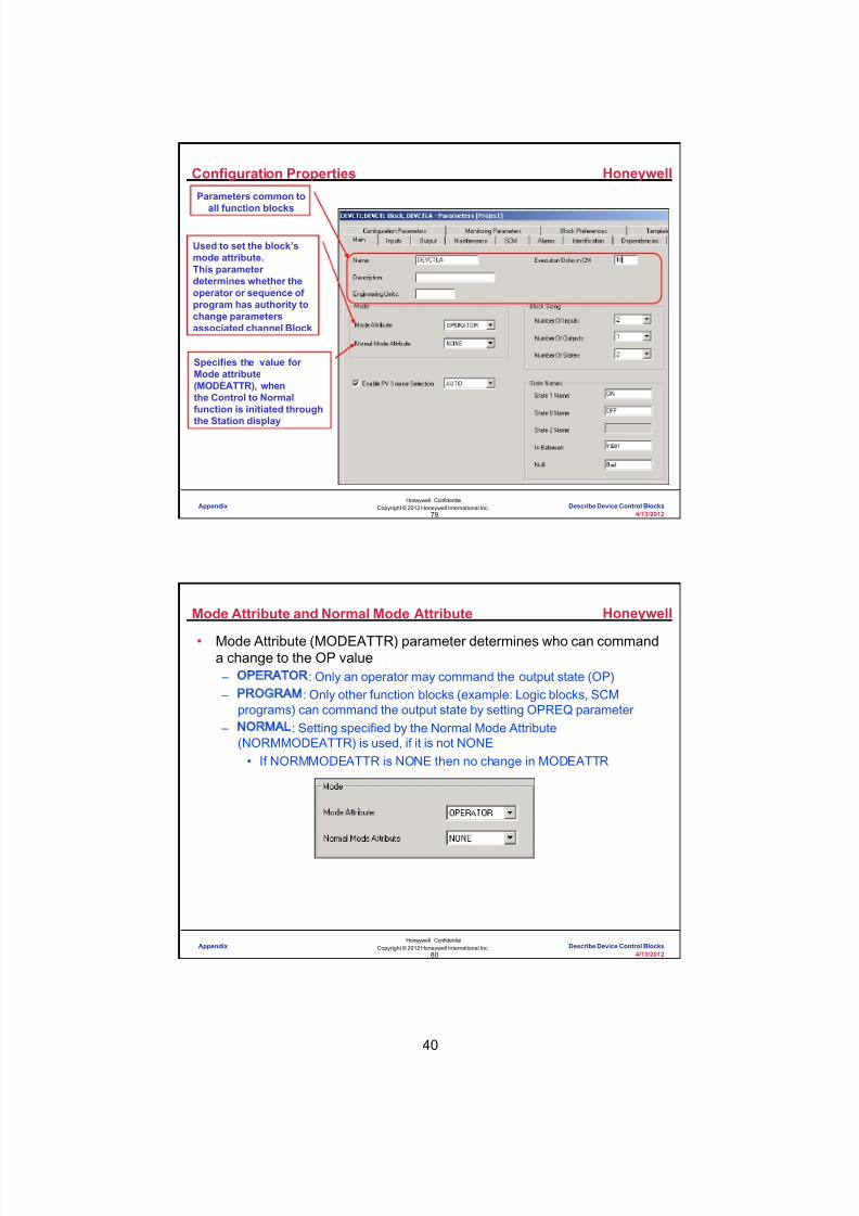
8/9/2019 Student Course Book- Automation
http://slidepdf.com/reader/full/student-course-book-automation 1102/1165
40
Honeywell
Honeywell ConfidentialCopyright © 2012 Honeywell International Inc.
4/13/201279
Configuration PropertiesParameters common to
all function blocks
Used to set the block’smode attribute.This parameter determines whether theoperator or sequence of program has authority tochange parametersassociated channel Block
Specifies the value for Mode attribute(MODEATTR), whenthe Control to Normalfunction is initiated through
the Station display
Appendix Describe Device Control Blocks
Honeywell
Honeywell ConfidentialCopyright © 2012 Honeywell International Inc.
4/13/201280
Mode Attribute and Normal Mode Attribute
• Mode Attribute (MODEATTR) parameter determines who can commanda change to the OP value – OPERATOR : Only an operator may command the output state (OP) – PROGRAM : Only other function blocks (example: Logic blocks, SCM
programs) can command the output state by setting OPREQ parameter – NORMAL : Setting specified by the Normal Mode Attribute
(NORMMODEATTR) is used, if it is not NONE• If NORMMODEATTR is NONE then no change in MODEATTR
Appendix Describe Device Control Blocks
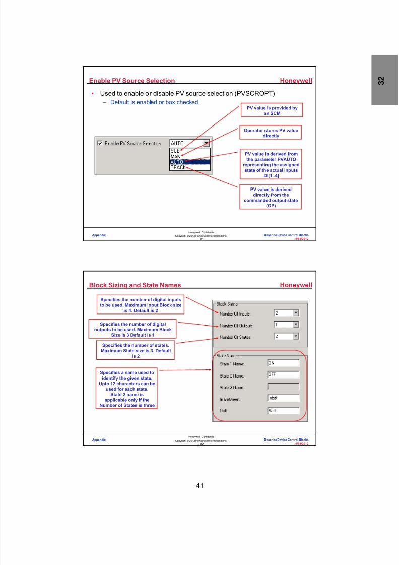
8/9/2019 Student Course Book- Automation
http://slidepdf.com/reader/full/student-course-book-automation 1103/1165
41
Honeywell
Honeywell ConfidentialCopyright © 2012 Honeywell International Inc.
4/13/201281
Enable PV Source Selection
PV value is provided byan SCM
Operator stores PV valuedirectly
PV value is derived fromthe parameter PVAUTO
representing the assignedstate of the actual inputs
DI[1..4]
PV value is deriveddirectly from the
commanded output state(OP)
• Used to enable or disable PV source selection (PVSCROPT) – Default is enabled or box checked
Appendix Describe Device Control Blocks
Honeywell
Honeywell ConfidentialCopyright © 2012 Honeywell International Inc.
4/13/201282
Block Sizing and State Names
Specifies the number of digital inputsto be used. Maximum input Block size
is 4. Default is 2
Specifies the number of digitaloutputs to be used. Maximum Block
Size is 3 Default is 1
Specifies the number of states.Maximum State size is 3. Default
is 2
Specifies a name used toidentify the given state.
Upto 12 characters can beused for each state.
State 2 name isapplicable only if theNumber of States is three
Appendix Describe Device Control Blocks

8/9/2019 Student Course Book- Automation
http://slidepdf.com/reader/full/student-course-book-automation 1104/1165
42
Honeywell
Honeywell ConfidentialCopyright © 2012 Honeywell International Inc.
4/13/201283
Input Tab
Same as theentry in Main tab
Shows the inputcombinations associated
with a given state. Acheck in the box for theinput represents its ONcondition and no checkfor its OFF position. The
default State is null (BAD)
• Inputs are Boolean values which represents the state of any other blockoutput or a field DICHANNEL (Digital Input Channel) block
Appendix Describe Device Control Blocks
Honeywell
Honeywell ConfidentialCopyright © 2012 Honeywell International Inc.
4/13/201284
Output Tab
Same as theentry in Main tab
• Outputs are configured as Boolean or Pulsed (On Pulse or Off Pulse)• The Number of Digital Outputs (NUMDOUTS) parameter is used to
select the number of active Digital/Pulse outputs – When this parameter is 0 (zero), other outputs and OP parameters have no
meaning
Appendix Describe Device Control Blocks

8/9/2019 Student Course Book- Automation
http://slidepdf.com/reader/full/student-course-book-automation 1105/1165
43
Honeywell
Honeywell ConfidentialCopyright © 2012 Honeywell International Inc.
4/13/201285
Output
• Each output is either Boolean or Pulsed (On Pulse or Off Pulse)
– Output (OP) value can be connected to any other block parameter or to afield DOCHANNEL (Digital Output Channel) block
• The DOCHANNEL (DOC) block connects to three different inputs from aDEVCTL block – DOC.SO may be connected to DO [1 .. 3] of DEVCTL block – DOC.ONPULSE may be connected to pulsed outputs PO [1 .. 3] of DEVCTL
block – DOC.OFFPULSE may be connected to pulsed outputs PO [1 .. 3] of
DEVCTL block – Only one input can be connected for any single DOC
Appendix Describe Device Control Blocks
Honeywell
Honeywell ConfidentialCopyright © 2012 Honeywell International Inc.
4/13/201286
Output States
Selects the state thatdefines the DEVCTLblock in a safe state.The default is State 0.State 2 selection is onlyapplicable if number ofstates (NUMSTATES) isthree
Used to specify the outputcombinations associated with agiven state. Check the box for theoutput to associate to ON conditionor leave it unchecked for its OFFposition. The default is OFF orunchecked
Appendix Describe Device Control Blocks

8/9/2019 Student Course Book- Automation
http://slidepdf.com/reader/full/student-course-book-automation 1106/1165
44
Honeywell
Honeywell ConfidentialCopyright © 2012 Honeywell International Inc.
4/13/201287
Pulse Output
• Enable / Disable thePulse Output (PO) – When enabled, the corresponding
output (PO[x]) pin is exposed onthe block
– Default is no pulse outputs configured – Selectable outputs depend upon the configured number of outputs
• Pulse Width is used to specify the width of a given output pulse – Range is 0 to 60 seconds – Configurable only when the output is configured as a pulse output – The default value is 1 second for all configured pulse outputs
Appendix Describe Device Control Blocks
Honeywell
Honeywell ConfidentialCopyright © 2012 Honeywell International Inc.
4/13/201288
Pulse Width
• DOCHANNEL block determines the actual pulse width resolution andaccuracy based on its execution rate – Rounds up the configured pulse width value consistent with its own
execution rate.• If the execution rate of the DOCHANNEL block is 125 milliseconds and
the configured PULSEWIDTH value is 450 milliseconds (.45 seconds),the actual pulse time output would be 500 milliseconds, which is the nexthighest multiple of 125 milliseconds
• A PULSEWIDTH value of 0 is a special case – If a 0 pulse is sent to ONPULSE or OFFPULSE, the DOCHANNEL block
immediately turns OFF any existing pulse
Appendix Describe Device Control Blocks
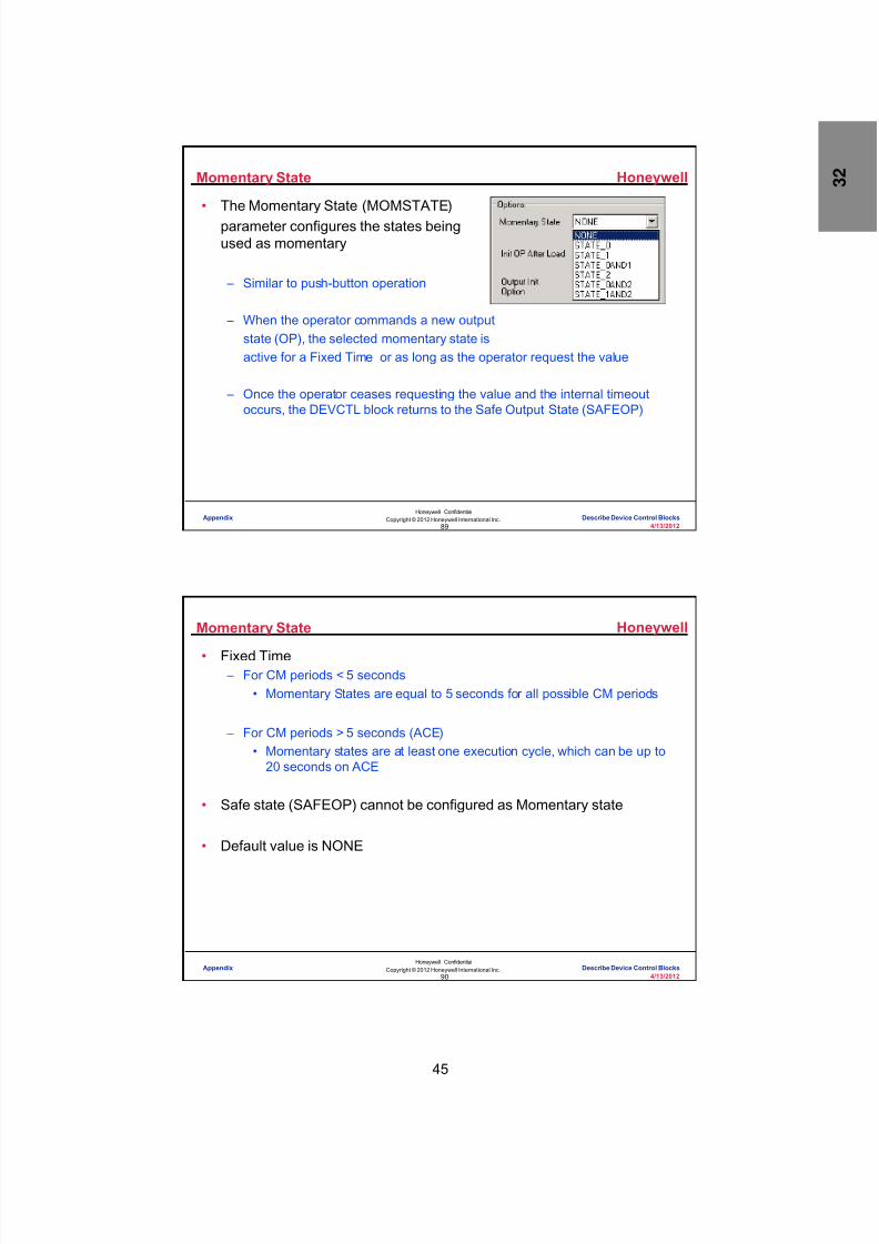
8/9/2019 Student Course Book- Automation
http://slidepdf.com/reader/full/student-course-book-automation 1107/1165
45
Honeywell
Honeywell ConfidentialCopyright © 2012 Honeywell International Inc.
4/13/201289
Momentary State
• The Momentary State (MOMSTATE)parameter configures the states beingused as momentary
– Similar to push-button operation
– When the operator commands a new outputstate (OP), the selected momentary state isactive for a Fixed Time or as long as the operator request the value
– Once the operator ceases requesting the value and the internal timeoutoccurs, the DEVCTL block returns to the Safe Output State (SAFEOP)
Appendix Describe Device Control Blocks
Honeywell
Honeywell ConfidentialCopyright © 2012 Honeywell International Inc.
4/13/201290
Momentary State
• Fixed Time – For CM periods < 5 seconds
• Momentary States are equal to 5 seconds for all possible CM periods
– For CM periods > 5 seconds (ACE)• Momentary states are at least one execution cycle, which can be up to
20 seconds on ACE
• Safe state (SAFEOP) cannot be configured as Momentary state
• Default value is NONE
Appendix Describe Device Control Blocks

8/9/2019 Student Course Book- Automation
http://slidepdf.com/reader/full/student-course-book-automation 1108/1165
46
Honeywell
Honeywell ConfidentialCopyright © 2012 Honeywell International Inc.
4/13/201291
Seal-In Option
• Seal-In option is used to clear output commands when the processfeedback state (PV) cannot follow the commanded output state (OP) – It is detected by the Command Disagree or Uncommanded Change alarms – Default it is unchecked or disabled
• If the Seal-In option is enabled and when PV does not follow thecommanded output, then – Field output destinations are set to the Safe Output State (SAFEOP), but OP
is not altered• OPFINAL shows the state which was commanded to the output
destinations – OPFINAL is set equal to OP on the next operator action to OP, which clears
the “seal” condition
• Seal-In option and Momentary state are mutually exclusive – Momentary state has to be None to configure the Seal-In option
Appendix Describe Device Control Blocks
Honeywell
Honeywell ConfidentialCopyright © 2012 Honeywell International Inc.
4/13/201292
Output Initialization
• The Output Init option (INITOPOPT) is used toconfigure Output Initialization option
• The following options are available – NORMALOPT - Performs Normal initialization
• When INITMAN parameter transitions from ON to OFF, the DeviceControl FB provides an output value (OP) as follows:
– If Safety Interlock is active, the OP is set to SAFEOP – If the Override Interlocks are active and not bypassed, the OP is set
to the highest priority Override Interlock – If LocalMan is ON
• OP tracks PV, if PV is in State0 or State1or State2• OP is set to SAFEOP, if PV is in Null or InBetween states or PV
does not exist
– SAFEOPOPT – Output is set to Safe output (SAFEOP)
Appendix Describe Device Control Blocks

8/9/2019 Student Course Book- Automation
http://slidepdf.com/reader/full/student-course-book-automation 1109/1165
47
Honeywell
Honeywell ConfidentialCopyright © 2012 Honeywell International Inc.
4/13/201293
Output Initialization
– HOLDOPOPT - Initialization will not be performed
• OP remains the last value – HOLDOPOPT with Legacy Output Init Option (LEGACYINITOPT)
• OP remains on last value• When the Device Control recovers from the initialization manual
condition, the output is not sent to the output point unless an overrideinterlock or safety interlock is active and not bypassed
Appendix Describe Device Control Blocks
Honeywell
Honeywell ConfidentialCopyright © 2012 Honeywell International Inc.
4/13/201294
Permissive and Override Interlock Bypassing
Used to enable or disable thebypass for Permissive and Override
Interlocks. Default is disabled
Used to Bypass the Permissive andOverride Interlocks. When this
parameter is Enabled, the OP canbe changed regardless of the state
of Override and Permissiveinterlocks (Does not affect the
Safety Override Interlock). When itis OFF, existing Override Interlocks(OI[0..2]) takes effect . The default is
OFF
Appendix Describe Device Control Blocks

8/9/2019 Student Course Book- Automation
http://slidepdf.com/reader/full/student-course-book-automation 1110/1165
48
Honeywell
Honeywell ConfidentialCopyright © 2012 Honeywell International Inc.
4/13/201295
Init OP After Load
• Init OP After Load (INITOPAFTLD)parameter is used to configure theinitialization values of digital outputs (DOs)to their desired values – Used for the strategy where the outputs of a DevCtl FB is connected to non-
initializable blocks (Logic blocks)
• Default option initializes the OP to State0
Appendix Describe Device Control Blocks
Honeywell
Honeywell ConfidentialCopyright © 2012 Honeywell International Inc.
4/13/201296
• Interlock Strategies are implemented using Permissives, OverrideInterlocks, and the Safety Interlock• Permissive P(0-2)
– There is a Permissive for each state – Normally ON – Operator can select the state if it’s
Permissive is asserted (ON) – Can be Bypassed
• Override Interlock OI(0-2) – There is an Override Interlock for each state – Normally OFF – When an Override Interlock is asserted (ON)
the Output is forced to it’s state – Can be Bypassed
• Safety Interlock SI – Normally OFF – Sets the Output to the Safe State when asserted (ON) – Cannot be Bypassed
Permissives and Interlocks
Appendix Describe Device Control Blocks

8/9/2019 Student Course Book- Automation
http://slidepdf.com/reader/full/student-course-book-automation 1111/1165
49
Honeywell
Honeywell ConfidentialCopyright © 2012 Honeywell International Inc.
4/13/201297
Maintenance Tab
Enable or Disable collection of
Maintenance Statistics. Default itis disabled
RESETFL Parameter is availableonly when the block is red
tagged. An user program oranother FB can turn ON the thisparameter to reset the statistics
anytime
Accumulated time of PV in state1, since the last statistics reset
Accumulated number of safetyinterlock trips due to OP
changing state, since the laststatistics reset
Accumulated number oftransitions of PV to state 1,
since the last statistics reset
Maximum number of
hours of PVaccumulated in state 0
Maximum
number oftransitions ofPV accumulated
in state 0
Appendix Describe Device Control Blocks
Honeywell
Honeywell ConfidentialCopyright © 2012 Honeywell International Inc.
4/13/201298
SCM Tab
Used to select the Mode Trackingfunction for the SCM associatedwith this block’s Control Module
Specifies the action the functionblock is to take when the SCM goesto Starting state, Stop/Abort State
and Hold State
Used to select the Restart Stateoption. Applicable only when the
SCM state is Resume or Run
Appendix Describe Device Control Blocks

8/9/2019 Student Course Book- Automation
http://slidepdf.com/reader/full/student-course-book-automation 1112/1165
50
Honeywell
Honeywell ConfidentialCopyright © 2012 Honeywell International Inc.
4/13/201299
Alarms TabPriority and Severity levels for
Command Disagree, Command Fail,Uncommand change and Bad PV
alarmsSets the feedback time of different
states(0,1 and 2) for CommandDisagree and Command Fail alarms
Configure the priority and Severitylevels and Enable/Disable the SafetyOverride, Override and Off Normal
Alarms
Appendix Describe Device Control Blocks
Honeywell
Honeywell ConfidentialCopyright © 2012 Honeywell International Inc.
4/13/2012100
Commanding DeviceControl Block outputs from
SCMs
Appendix Describe Device Control Blocks

8/9/2019 Student Course Book- Automation
http://slidepdf.com/reader/full/student-course-book-automation 1113/1165
51
Honeywell
Honeywell ConfidentialCopyright © 2012 Honeywell International Inc.
4/13/2012101
Using Logic and Override/Interlocks
Logic and Override/Interlocks were usedto drive the Device Control block outputin the course labs – as in the case of thetemplate FANLOGIC
In a simple example:
An SCM could write to a flag in the logicwhich could assert an Override/Interlock forcing the output to the associated state.
The following slides show several other methods for an SCM to command DeviceControl Module outputs:1) Generic OP – GOP2) Output Command - OPCMD
Appendix Describe Device Control Blocks
Honeywell
Honeywell ConfidentialCopyright © 2012 Honeywell International Inc.
4/13/2012102
Generic OP - GOP
The SCM writes to the GOP parameter on the device control block.This is the most commonly used device control command• Pros
– Simple direct programming of devices allowing flexible easy to understanddesigns
• Cons – Programming must be structured to prevent step output failures for device
control blocks with Override/Interlocks asserted or in Operator MODEATTR
Appendix Describe Device Control Blocks
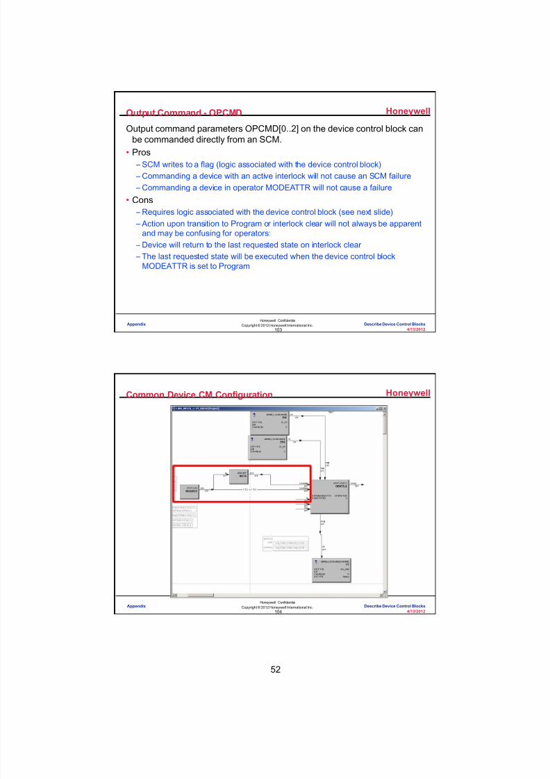
8/9/2019 Student Course Book- Automation
http://slidepdf.com/reader/full/student-course-book-automation 1114/1165

8/9/2019 Student Course Book- Automation
http://slidepdf.com/reader/full/student-course-book-automation 1115/1165
53
Honeywell
Honeywell ConfidentialCopyright © 2012 Honeywell International Inc.
4/13/2012105
Conclusion
Describe Device Control Blocks
CompletionCertificate
Proceed to the next lesson in your course material.
Appendix Describe Device Control Blocks
Honeywell
Honeywell ConfidentialCopyright © 2012 Honeywell International Inc.
4/13/2012106
This page intentionally left blank
Appendix Describe Device Control Blocks

8/9/2019 Student Course Book- Automation
http://slidepdf.com/reader/full/student-course-book-automation 1116/1165
54
107
Honeywell ConfidentialCopyright © 2012 Honeywell International Inc.
4/13/2012
Describe the HPM Functions Duplicated inCEE
Appendix Describe the HPM Functions Duplicated in CEEAppendix Describe the HPM Functions Duplicated in CEE
Honeywell
Honeywell ConfidentialCopyright © 2012 Honeywell International Inc.
4/13/2012108
Introduction
• Enhanced HPM algorithms is introduced in R300 for CEE. – Regulatory Summer
– Signal Selector
– Reverse Output
• Supported in
– ACE
– C200
– C200E
– C300
– SIM-ACE
– SIM-C200
– SIM-C200E
– SIM-C300
Appendix Describe the HPM Functions Duplicated in CEE

8/9/2019 Student Course Book- Automation
http://slidepdf.com/reader/full/student-course-book-automation 1117/1165
55
Honeywell
Honeywell ConfidentialCopyright © 2012 Honeywell International Inc.
4/13/2012109
Regulatory Summer
• Regulatory control block
• Has four inputs X1 to X4
• Provides scaling factor for each input
Appendix Describe the HPM Functions Duplicated in CEE
Honeywell
Honeywell ConfidentialCopyright © 2012 Honeywell International Inc.
4/13/2012110
• Algorithm – Sum four scaled inputs. Add overall gain and overall bias.
• X1 is an initializable input for this block while other inputs are non-initializable.
Regulatory Summer
Appendix Describe the HPM Functions Duplicated in CEE

8/9/2019 Student Course Book- Automation
http://slidepdf.com/reader/full/student-course-book-automation 1118/1165
56
Honeywell
Honeywell ConfidentialCopyright © 2012 Honeywell International Inc.
4/13/2012111
Signal Selector
• Six input Auxiliary Block
• Combines HPM’s HiLoAvg and MidOf3
Appendix Describe the HPM Functions Duplicated in CEE
Honeywell
Honeywell ConfidentialCopyright © 2012 Honeywell International Inc.
4/13/2012112
• Algorithms possible – MINIMUM (MIN)
– MAXIMUM (MAX)
– MEDIAN (MED)
– AVERAGE (AVG)
– MULTIPLEXER (MUX)
Signal Selector
Appendix Describe the HPM Functions Duplicated in CEE

8/9/2019 Student Course Book- Automation
http://slidepdf.com/reader/full/student-course-book-automation 1119/1165
57
Honeywell
Honeywell ConfidentialCopyright © 2012 Honeywell International Inc.
4/13/2012113
• Provides reverse output
Reverse Output
Reverse Output Option
Appendix Describe the HPM Functions Duplicated in CEE
Honeywell
Honeywell ConfidentialCopyright © 2012 Honeywell International Inc.
4/13/2012114
• We have learned about the two native function blocks added in R300: – Regulatory Summer
– Signal Selector
– Reverse Output
Summary
Appendix Describe the HPM Functions Duplicated in CEE

8/9/2019 Student Course Book- Automation
http://slidepdf.com/reader/full/student-course-book-automation 1120/1165
58
Honeywell
Honeywell ConfidentialCopyright © 2012 Honeywell International Inc.
4/13/2012115
Conclusion
Describe the HPM Functions Duplicated in CEE
Proceed to the next lesson in your course material
CompletionCertificate
Conclusion
Appendix Describe the HPM Functions Duplicated in CEE
Honeywell
Honeywell ConfidentialCopyright © 2012 Honeywell International Inc.
4/13/2012116
This page intentionally left blank
Appendix Describe the HPM Functions Duplicated in CEE

8/9/2019 Student Course Book- Automation
http://slidepdf.com/reader/full/student-course-book-automation 1121/1165
59
117
Honeywell ConfidentialCopyright © 2012 Honeywell International Inc.
4/13/2012
Describe Power Generation Function Blocks
Appendix Describe Power Generation Function BlocksAppendix Describe Power Generation Function Blocks
Honeywell
Honeywell ConfidentialCopyright © 2012 Honeywell International Inc.
4/13/2012118
Topics
• Power Function blocks
Appendix Describe Power Generation Function Blocks

8/9/2019 Student Course Book- Automation
http://slidepdf.com/reader/full/student-course-book-automation 1122/1165
60
Honeywell
Honeywell ConfidentialCopyright © 2012 Honeywell International Inc.
4/13/2012119
Power Function Blocks
• Power Function blocks are primarily aimed at providing processstrategies specific to the Power Generation market
• Twelve strategies (for C300/ C200E) have been identified and listedbelow – These blocks cannot be used in a C200 controller
No. Functi on Block
1 Digital Acquisit ion ( DIGACQ in Utility Library)
2 Cont ac t Monit oring ( CONTACTMON in Logic Library)
3 Rate of Change ( ROC in Auxiliary Library)
4 F irs t Ou t Detec tion FB ( FIRSTOUT in Utility Library)
5 Drum Level Computat ion Block ( LEVELCOMP in Powergen Library)
6 Main - I BV Logic FB ( MAINIBV in Powergen Library)
7 HT Motor Control Function Block ( HTMOTOR in Powergen Library)
8 LT Motor Control Function Block ( LTMOTOR in Powergen Library)
9 Valve / Damper Control Function Block ( VALVEDAMPER in Powergen Library)
10 Solenoid Valve Control Function Block ( SOLENOID in Powergen Library)
11 Alarm Annunciator Function Block ( ALMPANEL , ALMWINDOW in Utility Library)
12 Group capability and runback ( GRPCAPRBK in Powergen Library)
Appendix Describe Power Generation Function Blocks
Honeywell
Honeywell ConfidentialCopyright © 2012 Honeywell International Inc.
4/13/2012120
Digital Acquisition Block
• The Digital Acquisition function block is used when the PVSOURCE isdefined by the operator – Input to this block is from a DI channel when PVSource is AUTO – Input to this block is from the operator when PVSource is MAN – Any block with a digital output can be the input when PVSource is SUB
• Reduces the PU and MU usage vs DevCtl block
• This block is independent of the Channel type feeding the block
• In the Utility library
Appendix Describe Power Generation Function Blocks

8/9/2019 Student Course Book- Automation
http://slidepdf.com/reader/full/student-course-book-automation 1123/1165
61
Honeywell
Honeywell ConfidentialCopyright © 2012 Honeywell International Inc.
4/13/2012121
Contact Monitoring (CONTACTMON) Block
• The Contact Monitoring block is used to generate an alarm wheneverthe state of both inputs is simultaneously ON or OFF based on theNORMAL alarm state configuration
• The Contact Monitoring block is used for limit switches with NO and NCcontacts with the same activation mechanism
• In the LOGIC library
Appendix Describe Power Generation Function Blocks
Honeywell
Honeywell ConfidentialCopyright © 2012 Honeywell International Inc.
4/13/2012122
Functions of CONTACTMON
• Enables alarm generation whenever the state of both inputs is the sameor different based on the normal alarm state configuration
• Provides the state at IN[1] and IN[2] as OUT1 and OUT2
• PVFL gives the negated XOR results of IN[1] and IN[2]
• When NORMAL is State0, an alarm will be generated whenever the
state of both inputs is the same
• When NORMAL is State1, an alarm will be generated whenever thestate of both inputs is different
IN[1] IN[2] PVFLON ON ONON OFF OFFOFF ON OFFOFF OFF ON
Appendix Describe Power Generation Function Blocks

8/9/2019 Student Course Book- Automation
http://slidepdf.com/reader/full/student-course-book-automation 1124/1165
62
Honeywell
Honeywell ConfidentialCopyright © 2012 Honeywell International Inc.
4/13/2012123
Rate of Change (ROC) Block
• Rate of Change block is a computational block used on the input side ofControl blocks for limiting the input variable (typically SP)
• In Power plants, speed of HT motors requires control without exceedingthe rate of change of the current
• In some temperature control applications,dynamic profiling is needed based on thedeviation of SP and actual temperature
• In the Auxiliary library
Appendix Describe Power Generation Function Blocks
Honeywell
Honeywell ConfidentialCopyright © 2012 Honeywell International Inc.
4/13/2012124
Rate of Change (ROC) Functions
• If the input variation is more than the rate trip limit in either direction, therate of change of output is limited to the change specified by the rate triplimit – The output changes at the specified rate limits until the value is equal to the
input variable
Appendix Describe Power Generation Function Blocks
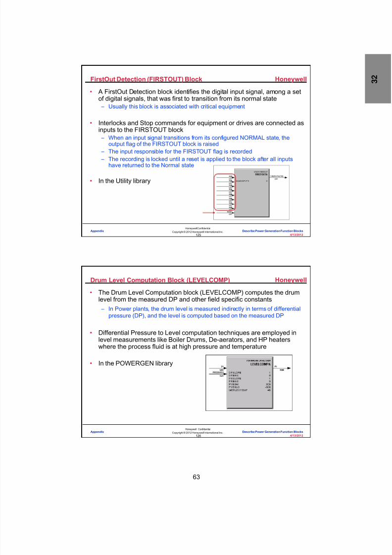
8/9/2019 Student Course Book- Automation
http://slidepdf.com/reader/full/student-course-book-automation 1125/1165
63
Honeywell
Honeywell ConfidentialCopyright © 2012 Honeywell International Inc.
4/13/2012125
FirstOut Detection (FIRSTOUT) Block
• A FirstOut Detection block identifies the digital input signal, among a setof digital signals, that was first to transition from its normal state – Usually this block is associated with critical equipment
• Interlocks and Stop commands for equipment or drives are connected asinputs to the FIRSTOUT block – When an input signal transitions from its configured NORMAL state, the
output flag of the FIRSTOUT block is raised – The input responsible for the FIRSTOUT flag is recorded – The recording is locked until a reset is applied to the block after all inputs
have returned to the Normal state
• In the Utility library
Appendix Describe Power Generation Function Blocks
Honeywell
Honeywell ConfidentialCopyright © 2012 Honeywell International Inc.
4/13/2012126
Drum Level Computation Block (LEVELCOMP)
• The Drum Level Computation block (LEVELCOMP) computes the drumlevel from the measured DP and other field specific constants – In Power plants, the drum level is measured indirectly in terms of differential
pressure (DP), and the level is computed based on the measured DP
• Differential Pressure to Level computation techniques are employed inlevel measurements like Boiler Drums, De-aerators, and HP heaterswhere the process fluid is at high pressure and temperature
• In the POWERGEN library
Appendix Describe Power Generation Function Blocks

8/9/2019 Student Course Book- Automation
http://slidepdf.com/reader/full/student-course-book-automation 1126/1165
64
Honeywell
Honeywell ConfidentialCopyright © 2012 Honeywell International Inc.
4/13/2012127
Drum Level Computation Block (LEVELCOMP)
• The equation for computing drum level:
h = ( H (ρ Ref - ρ S ) – DP ) / (ρ W - ρ S )
where – h: Drum level to be measured – H: Length of stand pipe – DP: Differential pressure of the drum – ρ Ref : Density of water in wet leg (This
computation uses the Water Legtemperature)
– ρ S : Density of steam – ρ W : Density of water
Appendix Describe Power Generation Function Blocks
Honeywell
Honeywell ConfidentialCopyright © 2012 Honeywell International Inc.
4/13/2012128
Main – IBV Logic Function Block (MAINIBV)
• The Main – IBV (Integral Bypass Valve) Logic function block (MAINIBV)has a user configurable DELAY parameter for providing a time delaybefore releasing an open command to the main valve – Timer starts when the IBV open feedback is sensed by the block
• In the POWERGEN library
Appendix Describe Power Generation Function Blocks

8/9/2019 Student Course Book- Automation
http://slidepdf.com/reader/full/student-course-book-automation 1127/1165
65
Honeywell
Honeywell ConfidentialCopyright © 2012 Honeywell International Inc.
4/13/2012129
Drive Control Blocks
• Prior to R310 “Drive Control” was accomplished using Device ControlBlocks (DEVCTL) – The existing Device Control Block was designed for all types of drives such
as LT, HT, and valves – There is a single permissive and interlock input for each state – All switchgear-related inputs and process inputs had to be connected to this
one single input pin by employing OR/AND blocks for multiplexing
• Four different drive control blocks have been developed and are locatedin the POWERGEN library – Valve / Damper Control (VALVEDAMPER) – Solenoid Valve Control (SOLENOID) – LT Motor Control (LTMOTOR)
– HT Motor Control (HTMOTOR)• These blocks are derived from the DEVCTL block and customized to
meet Drive Control requirements
Appendix Describe Power Generation Function Blocks
Honeywell
Honeywell ConfidentialCopyright © 2012 Honeywell International Inc.
4/13/2012130
Alarm Annunciator Function Blocks
• The Alarm Annunciator FB are used to implement the annunciationsequence for alarm groups connected to window annunciators
• The alarm annunciator is implemented as two blocks: – ALMWINDOW - Encapsulates the function of individual alarm groups – ANNPANEL - Controls the lamp test, acknowledge, and reset functions
• The Alarm Window function block accepts Boolean inputs (1 to 16) andperforms the configured sequence – It provides one alarm output (ALMOUT) and group status output (FLSHSTAT)
• The Annunciator Panel function block accepts the FLSHSTAT from Alarm Window function block and provides:
– Lamp output for the annunciation windows with synchronized lamp flashsequence – Hooter annunciation
• In the Utility library
Appendix Describe Power Generation Function Blocks

8/9/2019 Student Course Book- Automation
http://slidepdf.com/reader/full/student-course-book-automation 1128/1165
66
Honeywell
Honeywell ConfidentialCopyright © 2012 Honeywell International Inc.
4/13/2012131
Group Capability and Runback Block
• The Group Capability and Runback function block provides the GroupCapability and Group Runback Rate for the unit represented by theconfigured equipment
• Accepts equipments’ status inputs and desired unit load set point
• Number of devices connected is configurable
• In the POWERGEN library
Appendix Describe Power Generation Function Blocks
Honeywell
Honeywell ConfidentialCopyright © 2012 Honeywell International Inc.
4/13/2012132
Conclusion
Describe Power Generation Function Blocks
CompletionCertificate
Proceed to the next lesson in your course material.
Appendix Describe Power Generation Function Blocks
8/9/2019 Student Course Book- Automation
http://slidepdf.com/reader/full/student-course-book-automation 1129/1165
67
133
Honeywell ConfidentialCopyright © 2012 Honeywell International Inc.
4/13/2012
Describe the HART Functionality inC200/C200E Operations
Appendix Describe the HART Functionality in C200/C200E OperationsAppendix Describe the HART Functionality in C200/C200E Operations
Honeywell
Honeywell ConfidentialCopyright © 2012 Honeywell International Inc.
4/13/2012134
• In this lesson, you will learn about HART device functionality.
• At the conclusion of this lesson, you will be able to:
– Describe HART signals
– Distinguish among HART universal, common practice and device-specificcommands
– Explain how the device description (DD) files are loaded to the system
– Describe the types and characteristics ofHART-enabled I/O
– Distinguish between HART control-related data andoffline data and how they flow through the system
– Explain the purpose of the general status anddevice-specific status for a HART device andwhere the statuses can be viewed in the system
Introduction
Appendix Describe the HART Functionality in C200/C200E Operations

8/9/2019 Student Course Book- Automation
http://slidepdf.com/reader/full/student-course-book-automation 1130/1165
68
Honeywell
Honeywell ConfidentialCopyright © 2012 Honeywell International Inc.
4/13/2012135
Topics
• HART Signals• HART Commands
• HART Device Description Manager
• HART-Enabled I/O
• HART Data
• HART Device Status
Appendix Describe the HART Functionality in C200/C200E Operations
Honeywell
Honeywell ConfidentialCopyright © 2012 Honeywell International Inc.
4/13/2012136
HART Signal Characteristics
• Traditional wiring and well understood implementation• Hybrid (analog and digital signals)• Command/response (half-duplex) communication structure
4 mA -
20 mA -
1200Hz“1”
2200Hz“0”
+0.5 mA
- 0.5 mA
FSK The digital signal rides on top of the4-20 mA DC analog signal
Appendix Describe the HART Functionality in C200/C200E Operations

8/9/2019 Student Course Book- Automation
http://slidepdf.com/reader/full/student-course-book-automation 1131/1165
69
Honeywell
Honeywell ConfidentialCopyright © 2012 Honeywell International Inc.
4/13/2012137
Device Signaling
HART Input Device:
24 Vdc
4-20 mA
HART Output Device:
4-20 mA
The HART digital signal is superimposed on thestandard 4-20 mA signal
All memory resident device data is accessed using thisdigital portion of the protocol
Digital component is always bidirectional
Appendix Describe the HART Functionality in C200/C200E Operations
Honeywell
Honeywell ConfidentialCopyright © 2012 Honeywell International Inc.
4/13/2012138
Topics
• HART Signals
• HART Commands
• HART Device Description Manager
• HART-enabled I/O
• HART Data
• HART Device Status
Appendix Describe the HART Functionality in C200/C200E Operations

8/9/2019 Student Course Book- Automation
http://slidepdf.com/reader/full/student-course-book-automation 1132/1165
70
Honeywell
Honeywell ConfidentialCopyright © 2012 Honeywell International Inc.
4/13/2012139
HART Command Ranges
• Universal Commands 0-30):
– Represents the basic command set required by most HART devices – All commands in this set must be supported by all HART devices – Commands must be implemented exactly as specified by the HART foundation specification – DD interpretation is not required for this command set
• Common Practice Commands 32-121):
– A set of commands applicable to a wide range of devices – This command set should be supported by devices whenever possible, but this is not mandatory – Although the function of each command is well defined by the HART foundation specification,
the actual meaning of the r esponse data may require the interpretation of vendor DD files
• Device-specific Commands 128-253):
– This Command set is completely defined by the device vendor
– Each command performs a function that is specific to the particular device type and model – The use of these commands requires full interpretation of the vendor DD files
DD -Device description file
Appendix Describe the HART Functionality in C200/C200E Operations
Honeywell
Honeywell ConfidentialCopyright © 2012 Honeywell International Inc.
4/13/2012140
Device-specific Commands
• Device-specific commands (128-253) are set by the devicemanufacturer, so they will be different for each manufacturer andproduct type
• Some examples of device-specific commands in the Honeywelltemperature transmitter are the ability to:
– Pick the specific input type: T, J, or K thermocouple; 3- or 4-wire RTD; etc.
– Alarm on input break detection
– Determine whether a meter is installed and determine its units and range
– Turn write protection on or off with password protection
Appendix Describe the HART Functionality in C200/C200E Operations
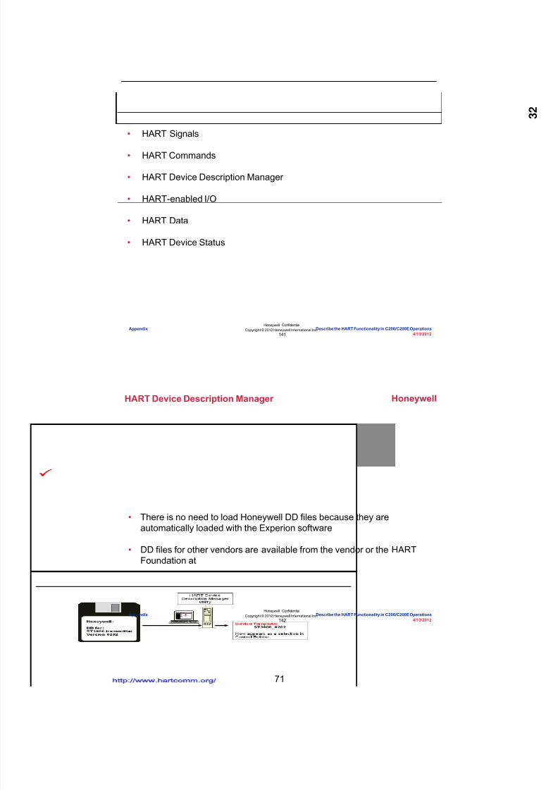
8/9/2019 Student Course Book- Automation
http://slidepdf.com/reader/full/student-course-book-automation 1133/1165
71
Honeywell
Honeywell ConfidentialCopyright © 2012 Honeywell International Inc.
4/13/2012141
Topics
• HART Signals• HART Commands
• HART Device Description Manager
• HART-enabled I/O
• HART Data
• HART Device Status
Appendix Describe the HART Functionality in C200/C200E Operations
Honeywell
Honeywell ConfidentialCopyright © 2012 Honeywell International Inc.
4/13/2012142
HART Device Description Manager
• There is no need to load Honeywell DD files because they areautomatically loaded with the Experion software
• DD files for other vendors are available from the vendor or the HARTFoundation at http://www.hartcomm.org/
Appendix Describe the HART Functionality in C200/C200E Operations
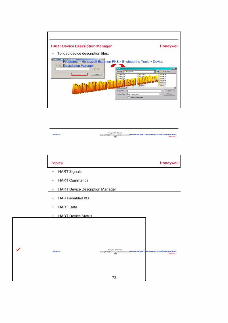
8/9/2019 Student Course Book- Automation
http://slidepdf.com/reader/full/student-course-book-automation 1134/1165
72
Honeywell
Honeywell ConfidentialCopyright © 2012 Honeywell International Inc.
4/13/2012143
HART Device Description Manager
• To load device description files:
– Programs > Honeywell Experion PKS > Engineering Tools > DeviceDescription Manager
Appendix Describe the HART Functionality in C200/C200E Operations
Honeywell
Honeywell ConfidentialCopyright © 2012 Honeywell International Inc.
4/13/2012144
Topics
• HART Signals
• HART Commands
• HART Device Description Manager
• HART-enabled I/O
• HART Data
• HART Device Status
Appendix Describe the HART Functionality in C200/C200E Operations

8/9/2019 Student Course Book- Automation
http://slidepdf.com/reader/full/student-course-book-automation 1135/1165
73
Honeywell
Honeywell ConfidentialCopyright © 2012 Honeywell International Inc.
4/13/2012145
Non-redundant CIOM-AChassis I/O format
8-channel HART AI8-channel HART AO
Redundant PMIOChassis I/O format
16-channel HART AI16-channel HART AO
HART-enabled I/O
Appendix Describe the HART Functionality in C200/C200E Operations
Honeywell
Honeywell ConfidentialCopyright © 2012 Honeywell International Inc.
4/13/2012146
HART-enabled I/O - Direct Connection
C200/C200E/C200/C200EE
Redundant HARTPM AI and AO IOP(16 channels/IOP)
Non-redundant HARTCIOM-A (1756) AI and AO IOM(8 channels/IOM)
Experion PKS Server
Characteristics:
Reduced hardware and physical foot print
One communication network
HART variables are available for control
HART status is available for control
Effective/efficient status handling
All HART data is available through the system
All HART analog anddigital data passesthrough the HART-enabled I/O
Appendix Describe the HART Functionality in C200/C200E Operations

8/9/2019 Student Course Book- Automation
http://slidepdf.com/reader/full/student-course-book-automation 1136/1165
74
Honeywell
Honeywell ConfidentialCopyright © 2012 Honeywell International Inc.
4/13/2012147
Topics
• HART Signals• HART Commands
• HART Device Description Manager
• HART-enabled I/O
• HART Data
• HART Device Status
Appendix Describe the HART Functionality in C200/C200E Operations
Honeywell
Honeywell ConfidentialCopyright © 2012 Honeywell International Inc.
4/13/2012148
Device ID information (Tag, manufacturer, model, SN, etc.)
Software and hardware revision level
Dynamic variables (PV, SV, TV, FV)
Device variables up to 255 (Slot-0 through Slot-3)
General and device-specific status information
Range related information
Device material of construction
Full device setup and configuration information
Trends and test analysis data
I/O
ControlProcessor
HARTDevice
ControlSystem
HoneywellFieldDevice Manager
Control-related Data is Cached on the IOM
The HART command originates from the IOM/IOP and theresponse is cached in the IOM/IOP
Appendix Describe the HART Functionality in C200/C200E Operations

8/9/2019 Student Course Book- Automation
http://slidepdf.com/reader/full/student-course-book-automation 1137/1165
75
Honeywell
Honeywell ConfidentialCopyright © 2012 Honeywell International Inc.
4/13/2012149
Device ID information (Tag, manufacturer, model, SN, etc.)
Software and hardware revision level
Dynamic variables (PV, SV, TV, FV)
Device variables up to 255 (Slot-0 through Slot-3)
General and device-specific status information
Range related informationDevice material of construction
Full device setup and configuration information
Trends and test analysis data
I/O
Control
Processor
HARTDevice
ControlSystem
AssetManagementSystem
Offline Data is Passed Through
The HART offline data passes through the IOM/IOP and the softwaremultiplexer to the Asset Management System
Appendix Describe the HART Functionality in C200/C200E Operations
Honeywell
Honeywell ConfidentialCopyright © 2012 Honeywell International Inc.
4/13/2012150
Topics
• HART Signals
• HART Commands
• HART Device Description Manager
• HART-enabled I/O
• HART Data
• HART Device Status
Appendix Describe the HART Functionality in C200/C200E Operations
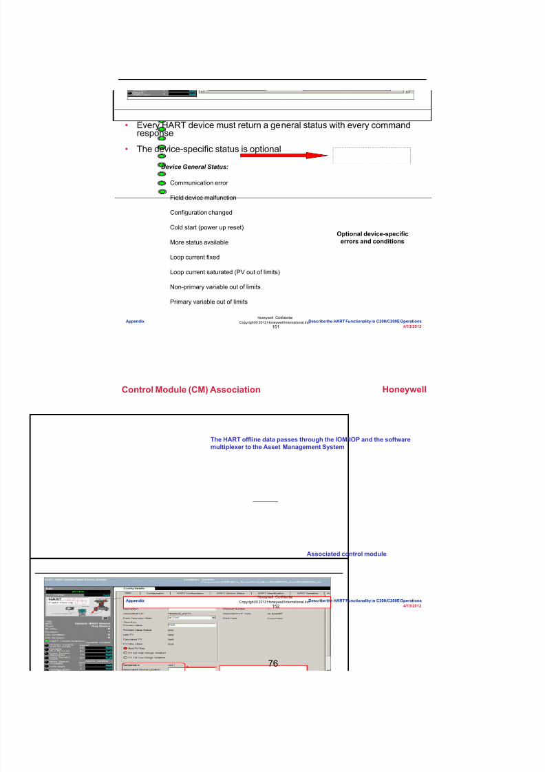
8/9/2019 Student Course Book- Automation
http://slidepdf.com/reader/full/student-course-book-automation 1138/1165
76
Honeywell
Honeywell ConfidentialCopyright © 2012 Honeywell International Inc.
4/13/2012151
Device General Status:
Communication error
Field device malfunction
Configuration changed
Cold start (power up reset)
More status available
Loop current fixed
Loop current saturated (PV out of limits)
Non-primary variable out of limits
Primary variable out of limits
Optional device-specificerrors and conditions
HART Device Status
• Every HART device must return a general status with every command
response• The device-specific status is optional
Appendix Describe the HART Functionality in C200/C200E Operations
Honeywell
Honeywell ConfidentialCopyright © 2012 Honeywell International Inc.
4/13/2012152
Control Module (CM) Association
The HART offline data passes through the IOM/IOP and the softwaremultiplexer to the Asset Management System
Associated control module
Appendix Describe the HART Functionality in C200/C200E Operations

8/9/2019 Student Course Book- Automation
http://slidepdf.com/reader/full/student-course-book-automation 1139/1165
77
Honeywell
Honeywell ConfidentialCopyright © 2012 Honeywell International Inc.
4/13/2012153
Sample - STT25H Device-specific Status
undefined7
undefined6
undefined5
NVM Conf Failed4
NVM Calib Failed3
Input Open2
Hardware Failure1
undefined0
User Correct Active7
undefined6
undefined5
In Output Mode4
Output Saturated3
Input out of Spec2
undefined1
CJ Over Temp0
4 Wires Configuration7
undefined6
undefined5
undefined4
undefined3
undefined2
undefined1
Suspect Input0
Host issues Command 48
Device responds with status
STT25H The STT25H uses only 3 of theavailable 17 bytes (byte 0, 1, and 2)
Byte – 0 Critical Byte – 1 Non-Critical Byte – 2 Information
Appendix Describe the HART Functionality in C200/C200E Operations
Honeywell
Honeywell ConfidentialCopyright © 2012 Honeywell International Inc.
4/13/2012154
Device-specific Status Can Be Used in Control
HoneywellSTT255
TemperatureTransmitter
undefined[7]7
undefined[6]6
undefined[5]5
NVM ConfFailed
[4]4
NVM CalibFailed
[3]3
Input Open[2]2
HardwareFailure
[1]1
undefined[0]0
HCMD48BT[#]Bit DD Descriptor Command 48 Byte-0
LOGIC: AND
ANDA
IN(1) IN(2)
LOGIC: ONDELAY
DELATADelay Time 30 sec
Control Module
HART AIBlock
HCMD48BT[1] pin
Appendix Describe the HART Functionality in C200/C200E Operations
8/9/2019 Student Course Book- Automation
http://slidepdf.com/reader/full/student-course-book-automation 1140/1165
78
Honeywell
Honeywell ConfidentialCopyright © 2012 Honeywell International Inc.
4/13/2012155
– HART signals have a high-frequency, bidirectional digital component and alow-frequency, unidirectional analog component.
– HART commands include:
• Universal commands that are mandatory and do not require DDs
• Common practice commands that are optional and may require DDs
• Device-specific commands defined by device vendors that require DDs
– Honeywell DD files are automatically loaded with the Experion softwarewhile non-Honeywell DD files are loaded using the DD Manager.
– The HART command originates in the IOM/IOP and the control-related dataare cached there.
– A HART device must return a general status with every command responsebut a device-specific status is optional.
Summary
• When working with HART devices, remember:
Appendix Describe the HART Functionality in C200/C200E Operations
Honeywell
Honeywell ConfidentialCopyright © 2012 Honeywell International Inc.
4/13/2012156
Conclusion
Describe the HART Functionality in C200/C200E Operations
CompletionCertificate
Proceed to the next lesson in your course material.
Appendix Describe the HART Functionality in C200/C200E Operations

8/9/2019 Student Course Book- Automation
http://slidepdf.com/reader/full/student-course-book-automation 1141/1165
79
157
Honeywell ConfidentialCopyright © 2012 Honeywell International Inc.
4/13/2012
Control Module Reference
Appendix Control Module ReferenceAppendix Control Module Reference
Honeywell
Honeywell ConfidentialCopyright © 2012 Honeywell International Inc.
4/13/2012158
FC01
Appendix Control Module Reference

8/9/2019 Student Course Book- Automation
http://slidepdf.com/reader/full/student-course-book-automation 1142/1165
80
Honeywell
Honeywell ConfidentialCopyright © 2012 Honeywell International Inc.
4/13/2012159
FC17
Appendix Control Module Reference
Honeywell
Honeywell ConfidentialCopyright © 2012 Honeywell International Inc.
4/13/2012160
FC18
Appendix Control Module Reference

8/9/2019 Student Course Book- Automation
http://slidepdf.com/reader/full/student-course-book-automation 1143/1165
81
Honeywell
Honeywell ConfidentialCopyright © 2012 Honeywell International Inc.
4/13/2012161
HS14A
Appendix Control Module Reference
Honeywell
Honeywell ConfidentialCopyright © 2012 Honeywell International Inc.
4/13/2012162
HS_A
Appendix Control Module Reference

8/9/2019 Student Course Book- Automation
http://slidepdf.com/reader/full/student-course-book-automation 1144/1165
82
Honeywell
Honeywell ConfidentialCopyright © 2012 Honeywell International Inc.
4/13/2012163
HS62
Appendix Control Module Reference
Honeywell
Honeywell ConfidentialCopyright © 2012 Honeywell International Inc.
4/13/2012164
HS63
Appendix Control Module Reference

8/9/2019 Student Course Book- Automation
http://slidepdf.com/reader/full/student-course-book-automation 1145/1165
83
Honeywell
Honeywell ConfidentialCopyright © 2012 Honeywell International Inc.
4/13/2012165
LC14
Appendix Control Module Reference
Honeywell
Honeywell ConfidentialCopyright © 2012 Honeywell International Inc.
4/13/2012166
PC16
Appendix Control Module Reference

8/9/2019 Student Course Book- Automation
http://slidepdf.com/reader/full/student-course-book-automation 1146/1165
84
Honeywell
Honeywell ConfidentialCopyright © 2012 Honeywell International Inc.
4/13/2012167
TI20
Appendix Control Module Reference
Honeywell
Honeywell ConfidentialCopyright © 2012 Honeywell International Inc.
4/13/2012168
This page intentionally left blank
Appendix Control Module Reference

8/9/2019 Student Course Book- Automation
http://slidepdf.com/reader/full/student-course-book-automation 1147/1165
4/13/2012 Copyright © 2012 Honeywell International Inc. 1
HPS Automation College written permission required to distributeHoneywell Confidential and Proprietary
Topic: Appendix
Contents
Guide to Debutanizer Model for C200E/C300 Labs .............................................................................. 3

8/9/2019 Student Course Book- Automation
http://slidepdf.com/reader/full/student-course-book-automation 1148/1165
2 Copyright © 2012 Honeywell International Inc. 4/13/2012
HPS Automation College written permission required to distributeHoneywell Confidential and Proprietary
This page was intentionally left blank.

8/9/2019 Student Course Book- Automation
http://slidepdf.com/reader/full/student-course-book-automation 1149/1165
4/13/2012 Copyright © 2012 Honeywell International Inc. 3
HPS Automation College written permission required to distributeHoneywell Confidential and Proprietary
Guide to Debutanizer Model for C200E/C300 Labs
Introduction
The C200E/C300 labs are a gradual progression of implementing a C200E/C300 controller.
• The labs use the Simulation Control Environment (SCE) feature of the ExperionPKS• The SCE is identical in most parts to the C200E/C300 Control Engineering Environment
(CEE)• The main difference is that the SCE uses simulated I/O, whereas the CEE uses real I/O• There are other differences in terms of execution cycle times, peer-to-peer functionality, but
these differences do not impact the lab exercises
The simulated I/O is driven by Sequential Control Modules simulating a Debutanizer.
This document provides details of the Debutanizer and the controls needed.
Process Description
The Debutanizer Model separates a blended feed using a distillation tower to produce the following products:
• C5 and heavier hydrocarbons which are sent to storage• C4 hydrocarbons and lighter hydrocarbons that are sent as feed to the Depropanizer
Note: Familiarity with distillation concepts is not required to complete the labs.
A very brief overview of the process is given below. A more detailed process flow is provided asan appendix
The Debutanizer P&ID can be found in a later section.

8/9/2019 Student Course Book- Automation
http://slidepdf.com/reader/full/student-course-book-automation 1150/1165
4 Copyright © 2012 Honeywell International Inc. 4/13/2012
HPS Automation College written permission required to distributeHoneywell Confidential and Proprietary
Process Equipment
The following table describes the process equipment used by the Debutanizer
Tag Description
D-100 Debutanizer Reflux Drum
T-100 Debutanizer
P-62 Reflux pump (from D-100 to T-100 )
P-63 Spare reflux pump (from D-100 to T-100)
P-68 Feed pump from (D-100 to Depropanizer)
P-69 Spare feed pump from (D-100 to Depropanizer)
E-100 Debutanizer Reboiler
E-110 Debutanizer Condenser
Control System
The following sections describe the instruments and control loops used in the distillation process.

8/9/2019 Student Course Book- Automation
http://slidepdf.com/reader/full/student-course-book-automation 1151/1165
4/13/2012 Copyright © 2012 Honeywell International Inc. 5
HPS Automation College written permission required to distributeHoneywell Confidential and Proprietary
Instrumentation
The following table lists the tagname and range for each instrument in the model.Items marked with an * are built by the student. The other items are imported.
SI Unit
Tag Description Range Units
11_AC12 T-100 Overheads Analyzer 0 - 2 mol % C 5
* 11_FC01 Heavy Feed to Debutanizer 0 - 600 m3 /hr
11_FC02 Light Feed to Debutanizer 0 - 70 m3 /hr
11_FC15 E-100 Steam Flow 0 - 62 T/hr
* 11_FC17 T-100 Bottom to Storage Tank 1 0 - 385 m3 /hr
* 11_FC18 T-100 Bottom to Off Specification Tank2
0 - 385 m3 /hr
11_FC19 Debutanizer Reflux 0 - 305 m3/hr
11_FC20 Depropanizer Feed 0 - 155 m3/hr
11_FC28 P-68/69 Minimum Flow Spillback 0 - 155 m3 /hr
11_HC41 D-100 Overhead to Flare 0 - 100 %
11_HC44 D-100 Bypass from CompressorInterstage Drum
0 - 100 %
* 11_HS14A E-110A Fan Stop - Start -
11_HS14B E-110B Fan Stop - Start -
11_HS14C E-110C Fan Stop - Start -
11_HS14D E-110D Fan Stop - Start -
11_HS14E E-110E Fan Stop - Start -
11_HS14F E-110F Fan Stop - Start -
11_HS14G E-110G Fan Stop - Start -
11_HS14H E-110H Fan Stop - Start -
* 11_HS62 P-62 Debutanizer Reflux Pump Stop - Start -
* 11_HS63 P-63 Debutanizer Reflux Pump Spare Stop - Start -
11_HS68 P-68 Depropanizer Feed Pump Stop - Start -
11_HS69 P-69 Depropanizer Feed Pump Spare Stop - Start -
* 11_LC14 T-100, Debutanizer Bottoms Level 0 - 100 %
11_LC16 D-100, Reflux Drum Level 0 - 100 %
11_LSD15 Debutanizer Bottoms Low Level Trip Shutdown - Normal -

8/9/2019 Student Course Book- Automation
http://slidepdf.com/reader/full/student-course-book-automation 1152/1165
6 Copyright © 2012 Honeywell International Inc. 4/13/2012
HPS Automation College written permission required to distributeHoneywell Confidential and Proprietary
SI Unit
Tag Description Range Units
11_PC15 T-100, Pressure Controller 700 -1750 kPag
* 11_PC16 D-100, Pressure Controller 700 - 1750 kPag11_PI14 T-100, Bottoms Pressure 0 - 1800 kPag
11_TC10 T-100, Tray 2, Reboiler 90 - 215 ° C
* 11_TI20 T-100, Bottoms 0 - 260 ° C
11_TI21 E-100, Reboiler Outlet 0 - 260 ° C
11_TI22 E-100, Reboiler Inlet 0 - 260 ° C
11_TI23 T-100, Tray 4 0 - 260 ° C
11_TI24 T-100, Tray 23 0 - 260 ° C
11_TI25 T-100, Overheads 0 - 260 °
C11_T126 T-100, Reflux 0 - 260 ° C
11_TI40 Heavy Feed Temperature 0 - 135 ° C

8/9/2019 Student Course Book- Automation
http://slidepdf.com/reader/full/student-course-book-automation 1153/1165
4/13/2012 Copyright © 2012 Honeywell International Inc. 7
HPS Automation College written permission required to distributeHoneywell Confidential and Proprietary
Control Loops and Lab Sequence
The first set of labs creates the continuous control modules needed for the Debutanizer to work. Thesteps involve building the control modules, loading and then testing the functions.
Lab 1: Configure C 200 Hardware
This lab is used to build the necessary C200E hardware. The steps create a C200E controller in theSimulated Control Environment (SCE), with the Control Processor, the CEE and all the I/Omodules needed. The modules are loaded to the controller at the end to verify correct operation. Theactual lab requires the building of several I/O modules. Other modules are imported into the project.The I/O list assignment is attached in Appendix 1.
Lab 2: Configure a Control Module for Data Acquisition
The point 11_TI20 is built in this lab. 11_TI20 will have alarming and will be seen in a group anddetail display. 11_TI20 also will be historized.
Lab 3: Configure a PID Control Module
The Heavy Feed Flow, 11_FC01 is built in this lab. The requirement is PID control, with bumplessAuto – Manual transfer. Alarms, groups and historization enabled. The module is built, loaded andactivated and then an SCM imported for simulation. This permits values to be seen. The remaining
modules, of a similar type, are then imported into the project with an appropriate SCM to simulatethe process values.

8/9/2019 Student Course Book- Automation
http://slidepdf.com/reader/full/student-course-book-automation 1154/1165
8 Copyright © 2012 Honeywell International Inc. 4/13/2012
HPS Automation College written permission required to distributeHoneywell Confidential and Proprietary
Lab 4: Configure a PID Control Module with Split Range outputs
The pressure in the reflux drum D 100 is controlled using two valves, with the following logic:• In case the pressure is below the setpoint, the drum is pressurized from the distillation tower,
T 100, through the PV 16 A valve.• In case the pressure is above the setpoint, the drum pressure is released through the PV 16 B
valve.PV16A valve is reverse acting and PV16B valves are direct acting.The following table illustrates how valves A and B open with the split range signal. Valve A is thevalve on the line bypassing the debutanizer overhead condenser E-110. Valve B is on the lineconnecting D-100 to the compressor interstage drum
Signal from PC16 Valve Condition
0 A Wide open
50 A Closed50 B Closed
100 B Open
The loop must be configured with bumpless transfer and the ability to operate the valves manually.An SCM will be imported, downloaded and activated to simulate values.
Lab 5: Configure a Cascade PID Control Module
The first Cascade loop is planned around LC14, the T 100 bottoms level control.
The P&ID shows that this loop has an interlock with the bottom safety valve, and is master to boththe outlet streams (FC 17 and FC 18).
11_LSD15 is an interlock valve, which trips in the event of low level. The trip is reset when thelevel is above 5%. The comparator for 5% will be built.
The interlock CM (11_LSD15) is imported into your project along with the appropriate SCM for process simulation.
The cascade loop, with 11_LC14 as master and 11_FC 17 as secondary, is then built, downloadedand operated. The loops require bumpless transfer, from CAS to AUTO to MAN.

8/9/2019 Student Course Book- Automation
http://slidepdf.com/reader/full/student-course-book-automation 1155/1165
4/13/2012 Copyright © 2012 Honeywell International Inc. 9
HPS Automation College written permission required to distributeHoneywell Confidential and Proprietary
Lab 6: Configure a Cascade PID Control Module with two secondaries
In this lab, the FC 18 loop is added as a secondary to the LC 14 loop built in the previous lab.Similar considerations of operation apply i.e., the loops require bumpless transfer, from CAS toAUTO to MAN.
In addition, the following requirements apply:• The ratio of the flow of FC 17 and FC 18 is 70:30• The addition of the two flows needs to be displayed
The module built in the previous lab is modified, downloaded and tested
The remaining cascade control modules and SCMs for simulation are then imported into the project.
Lab 7: Configure a Device Control Module – with Logic
The control logic for switching the fans of the Condenser, E 110, is developed in this lab.Operationally, the cooling fans are to be turned on, in case the top temperature, 11_TI25 is greaterthan a specified value. The operator initiates the start command, and each additional fan starts up asthe temperature increases.
Lab 8: Configure a Device Control Module – with Interlock
In this lab, the control for a pair of pumps, P62 and P63 is developed.
Operationally,• Start command is provided by the operator, for P62.• If P 62 does not start within 20 seconds from the start command, then P63 should start.• At any time, only one pump can be running.
The modules are built, loaded and tested.
The device control modules for the other pumps are then imported into the project along with 2 programs that permit the pumps to operate.

8/9/2019 Student Course Book- Automation
http://slidepdf.com/reader/full/student-course-book-automation 1156/1165
10 Copyright © 2012 Honeywell International Inc. 4/13/2012
HPS Automation College written permission required to distributeHoneywell Confidential and Proprietary
Conclusion
At the end of these labs, all the points would have been loaded, and the simulation would representthe Debutanizer in a steady operating state. The graphic, groups, trends and alarms would reflect the
plant operating conditions.
Note: There are several additional Sequential Control Modules that will be imported during the labexercises to simulate values. You will be given the names of the SCMs in the lab exercises.

8/9/2019 Student Course Book- Automation
http://slidepdf.com/reader/full/student-course-book-automation 1157/1165
4/13/2012 Copyright © 2012 Honeywell International Inc. 11
HPS Automation College written permission required to distributeHoneywell Confidential and Proprietary
P & I D

8/9/2019 Student Course Book- Automation
http://slidepdf.com/reader/full/student-course-book-automation 1158/1165
12 Copyright © 2012 Honeywell International Inc. 4/13/2012
HPS Automation College written permission required to distributeHoneywell Confidential and Proprietary
This page was intentionally left blank.

8/9/2019 Student Course Book- Automation
http://slidepdf.com/reader/full/student-course-book-automation 1159/1165
Appendix
Guide to Debutanizer Model for C200E/C300 Labs
4/13/2012 Copyright © 2012 Honeywell International Inc. 13
HPS Automation College written permission required to distributeHoneywell Confidential and Proprietary
Appendix 1 – C200E I/O list assignments
Sr.No
TagName
ModuleName
Channel IOM slotNumber
Remote I/OChassis MAC ID
CNET ModuleSlot Number
1 11_AC12.AI AI_3_4_4 0 3 4 4
2 11_FC19.FI AI_3_4_4 1 3 4 4
3 11_FC01.FI AI_3_4_4 2 3 4 4
4 11_FC02.FI AI_3_4_4 3 3 4 4
5 11_FC15.FI AI_3_4_4 4 3 4 4
6 11_TC10.TI AI_3_4_4 5 3 4 4
7 11_LC14.LI AI_5_4_4 0 5 4 4
8 11_FC17.FT AI_5_4_4 1 5 4 4
9 11_FC18.FI AI_5_4_4 2 5 4 4
10 11_FC28.FI AI_5_4_4 3 5 4 4
11 11_LC16.LI AI_5_4_4 4 5 4 4
12 11_FC20.FI AI_5_4_4 5 5 4 4
13 11_PC15.PI AI_5_4_4 6 5 4 4
14 11_PC16.PI AI_5_4_4 7 5 4 4
15 11_PI14.PI AI_8_4_4 0 8 4 4
16 11_TI20.TI AI_8_4_4 1 8 4 4
17 11_TI21.TI AI_8_4_4 2 8 4 4
18 11_TI22.TI AI_8_4_4 3 8 4 4
19 11_TI23.TI AI_8_4_4 4 8 4 4
20 11_TI25.TI AI_8_4_4 5 8 4 4
21 11_TI26.TI AI_8_4_4 6 8 4 4
22 11_TI40.TI AI_8_4_4 7 8 4 4

8/9/2019 Student Course Book- Automation
http://slidepdf.com/reader/full/student-course-book-automation 1160/1165
Appendix
Guide to Debutanizer Model for C200E/C300 Labs
14 Copyright © 2012 Honeywell International Inc. 4/13/2012
HPS Automation College written permission required to distributeHoneywell Confidential and Proprietary
Sr.No
TagName
ModuleName
Channel IOM slotNumber
Remote I/OChassis MAC ID
CNET ModuleSlot Number
23 11_TI24.TI AI_8_4_4 8 8 4 4
24 11_FC19.FV AO_4_4_4 0 4 4 4
25 11_FC01.FV AO_4_4_4 1 4 4 4
26 11_FC02.FV AO_4_4_4 2 4 4 4
27 11_FC15.FV AO_4_4_4 3 4 4 4
28 11_FC17.FY AO_4_4_4 4 4 4 4
29 11_FC28.FV AO_4_4_4 5 4 4 4
30 11_FC20.FY AO_4_4_4 6 4 4 4
31 11_FC18.FV AO_4_4_4 7 4 4 4
32 11_PC15.PV AO_7_4_4 0 7 4 4
33 11_PC16.PVA AO_7_4_4 1 7 4 4
34 11_PC16.PVB AO_7_4_4 2 7 4 4
35 11_HC41.HC AO_7_4_4 3 7 4 4
36 11_HC44.HC AO_7_4_4 4 7 4 4
39 11_HS14A.HI DI_10_4_4 0 10 4 4
40 11_HS14B.HI DI_10_4_4 1 10 4 4
41 11_HS14C.HI DI_10_4_4 2 10 4 4
42 11_HS14D.HI DI_10_4_4 3 10 4 4
43 11_HS14E.HI DI_10_4_4 4 10 4 4
44 11_HS14F.HI DI_10_4_4 5 10 4 4
45 11_HS14G.HI DI_10_4_4 6 10 4 4
46 11_HS14H.HI DI_10_4_4 7 10 4 4

8/9/2019 Student Course Book- Automation
http://slidepdf.com/reader/full/student-course-book-automation 1161/1165
Appendix
Guide to Debutanizer Model for C200E/C300 Labs
4/13/2012 Copyright © 2012 Honeywell International Inc. 15
HPS Automation College written permission required to distributeHoneywell Confidential and Proprietary
Sr.No
TagName
ModuleName
Channel IOM slotNumber
Remote I/OChassis MAC ID
CNET ModuleSlot Number
48 11_HS62.HI DI_10_4_4 9 10 4 4
49 11_HS63.HI DI_10_4_4 10 10 4 4
50 11_HS68.HI DI_10_4_4 11 10 4 4
51 11_HS69.HI DI_10_4_4 12 10 4 4
52 11_LSD15.LS DI_10_4_4 13 10 4 4
53 11_LC16.LSD15 DO_6_4_4 2 6 4 4
54 11_LSD15.HV39 DO_6_4_4 3 6 4 4
55 11_HS14A.HS DO_9_4_4 0 9 4 4
56 11_HS14B.HS DO_9_4_4 1 9 4 4
57 11_HS14C.HS DO_9_4_4 2 9 4 4
58 11_HS14D.HS DO_9_4_4 3 9 4 4
59 11_HS14E.HS DO_9_4_4 4 9 4 4
60 11_HS14F.HS DO_9_4_4 5 9 4 4
61 11_HS14G.HS DO_9_4_4 6 9 4 4
62 11_HS14H.HS DO_9_4_4 7 9 4 4
63 11_HS63.HS DO_9_4_4 9 9 4 4
64 11_HS62.HS DO_9_4_4 10 9 4 4
65 11_HS68.HS DO_9_4_4 11 9 4 4
66 11_HS69.HS DO_9_4_4 12 9 4 4

8/9/2019 Student Course Book- Automation
http://slidepdf.com/reader/full/student-course-book-automation 1162/1165
Appendix
Guide to Debutanizer Model for C200E/C300 Labs
16 Copyright © 2012 Honeywell International Inc. 4/13/2012
HPS Automation College written permission required to distributeHoneywell Confidential and Proprietary
Appendix 1 – C300 I/O list assignments
Sr.No
TagName
ModuleName
IOMNumber
Channel
1 11_AC12.AI C_AI_1 1 1
2 11_FC19.FI C_AI_1 1 4
3 11_FC01.FI C_AI_1 1 11
4 11_FC02.FI C_AI_1 1 2
5 11_FC15.FI C_AI_1 1 3
6 11_TC10.TI C_AI_1 1 10
7 11_LC14.LI C_AI_1 1 14
8 11_FC17.FT C_AI_1 1 12
9 11_FC18.FIC_AI_1 1 13
10 11_FC28.FIC_AI_1 1
6
11 11_LC16.LIC_AI_1 1
7
12 11_FC20.FIC_AI_1 1
5
13 11_PC15.PI C_AI_1 1 8
14 11_PC16.PI C_AI_1 1 15
15 11_PI14.PI C_AI_2 2 1

8/9/2019 Student Course Book- Automation
http://slidepdf.com/reader/full/student-course-book-automation 1163/1165
Appendix
Guide to Debutanizer Model for C200E/C300 Labs
4/13/2012 Copyright © 2012 Honeywell International Inc. 17
HPS Automation College written permission required to distributeHoneywell Confidential and Proprietary
Sr.No
TagName
ModuleName
IOMNumber
Channel
16 11_TI20.TIC_AI_2 2
2
17 11_TI21.TIC_AI_2 2
3
18 11_TI22.TIC_AI_2 2
4
19 11_TI23.TI C_AI_2 2 5
20 11_TI25.TI C_AI_2 2 7
21 11_TI26.TI C_AI_2 2 8
22 11_TI40.TI C_AI_2 2 9
23 11_TI24.TI C_AI_2 2 6
24 11_FC19.FV C_AO_4 4 3
25 11_FC01.FV C_AO_4 4 9
26 11_FC02.FV C_AO_4 4 1
27 11_FC15.FV C_AO_4 4 2
28 11_FC17.FYC_AO_4 4
10
29 11_FC28.FV C_AO_4 4 5
30 11_FC20.FYC_AO_4 4
4

8/9/2019 Student Course Book- Automation
http://slidepdf.com/reader/full/student-course-book-automation 1164/1165
Appendix
Guide to Debutanizer Model for C200E/C300 Labs
18 Copyright © 2012 Honeywell International Inc. 4/13/2012
HPS Automation College written permission required to distributeHoneywell Confidential and Proprietary
Sr.No
TagName
ModuleName
IOMNumber
Channel
31 11_FC18.FVC_AO_4 4
11
32 11_PC15.PV C_AO_4 4 8
33 11_PC16.PVA C_AO_4 4 12
34 11_PC16.PVB C_AO_4 4 13
35 11_HC41.HC C_AO_4 4 6
36 11_HC44.HC C_AO_4 4 7
39 11_HS14A.HIC_DI_6 6
1
40 11_HS14B.HIC_DI_6 6
2
41 11_HS14C.HIC_DI_6 6
3
42 11_HS14D.HI C_DI_6 64
43 11_HS14E.HI C_DI_6 6 5
44 11_HS14F.HI C_DI_6 6 6
45 11_HS14G.HI C_DI_6 6 7
46 11_HS14H.HI C_DI_6 6 8

8/9/2019 Student Course Book- Automation
http://slidepdf.com/reader/full/student-course-book-automation 1165/1165
Appendix
Guide to Debutanizer Model for C200E/C300 Labs
Sr.No
TagName
ModuleName
IOMNumber
Channel
48 11_HS62.HIC_DI_6 6
9
49 11_HS63.HIC_DI_6 6
10
50 11_HS68.HIC_DI_6 6
11
51 11_HS69.HI C_DI_6 6 13


![[AUTOMATION COURSE DETAILS] HEXBEDDED Technologieshexbedded.in/automation.pdf · [AUTOMATION COURSE DETAILS] HEXBEDDED Technologies SCADA: Supervisory Control and Data Acquisition](https://static.fdocuments.us/doc/165x107/5e816ae26be2d917887c392a/automation-course-details-hexbedded-t-automation-course-details-hexbedded-technologies.jpg)

