Student Attendance Recording System Woo Wing Hong A...
74
Student Attendance Recording System Woo Wing Hong A proposal submitted in partial fulfilment of the requirements for the award of Bachelor of Science (Hons.) Software Engineering Faculty of Engineering and Science Universiti Tunku Abdul Rahman August 2014
Transcript of Student Attendance Recording System Woo Wing Hong A...
Student Attendance Recording System
Woo Wing Hong
A proposal submitted in partial fulfilment of the
requirements for the award of Bachelor of Science
(Hons.) Software Engineering
Faculty of Engineering and Science
Universiti Tunku Abdul Rahman
August 2014
ii
DECLARATION
I hereby declare that this project report is based on my original work except for
citations and quotations which have been duly acknowledged. I also declare that it
has not been previously and concurrently submitted for any other degree or award at
UTAR or other institutions.
Signature :
Name : Woo Wing Hong
ID No. : 12 UEB 07679
Date :
iii
APPROVAL FOR SUBMISSION
I certify that this project report entitled “Student Attendance Recording System”
was prepared by Woo Wing Hong has met the required standard for submission in
partial fulfilment of the requirements for the award of Bachelor of Science (Hons.)
Software Engineering at Universiti Tunku Abdul Rahman.
Approved by,
Signature :
Supervisor : Lim Khong Leng
Date :

iv
The copyright of this report belongs to the author under the terms of the
copyright Act 1987 as qualified by Intellectual Property Policy of Universiti Tunku
Abdul Rahman. Due acknowledgement shall always be made of the use of any
material contained in, or derived from, this report.
© 2014, Woo Wing Hong. All right reserved.

v
ACKNOWLEDGEMENTS
I would like to thank everyone who had contributed to the successful completion of
this project. I would like to express my gratitude to my research supervisor, Mr. Lim
Khong Leng for his invaluable advice, guidance and his enormous patience
throughout the development of the research.
In addition, I would also like to express my gratitude to my loving parent and
friends who had helped and given me encouragement throughout my studies.
vi
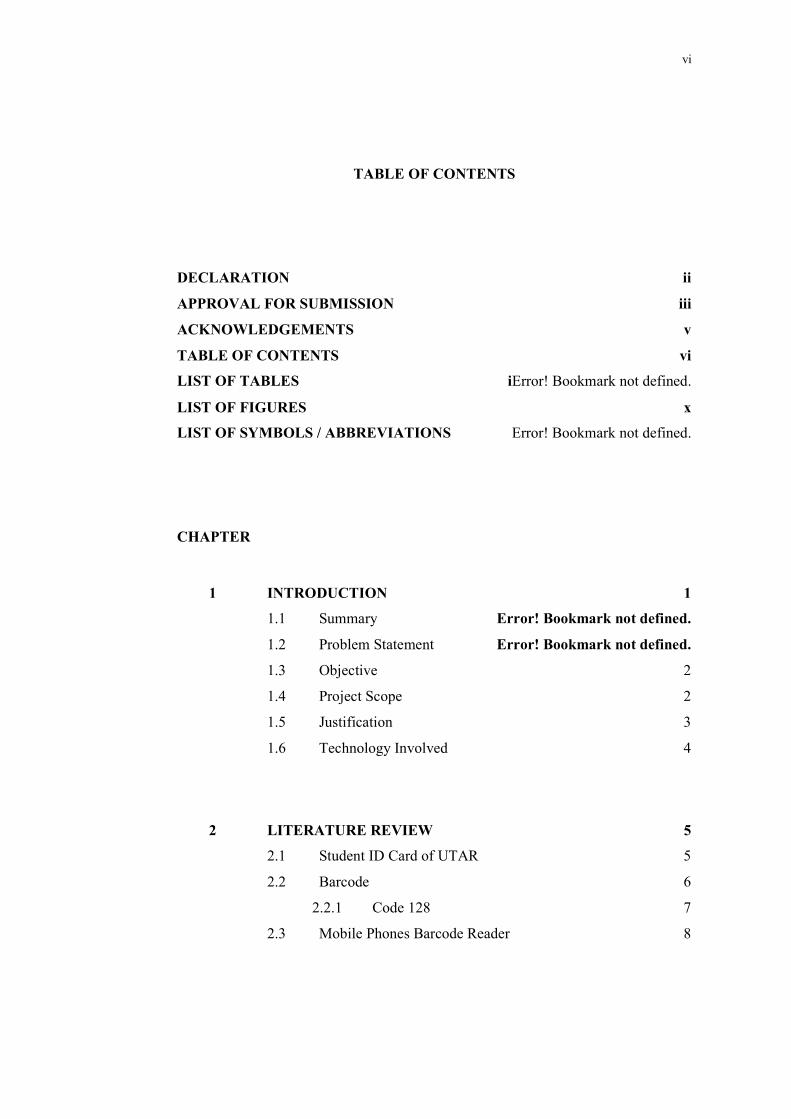
TABLE OF CONTENTS
DECLARATION ii
APPROVAL FOR SUBMISSION iii
ACKNOWLEDGEMENTS v
TABLE OF CONTENTS vi
LIST OF TABLES iError! Bookmark not defined.
LIST OF FIGURES x
LIST OF SYMBOLS / ABBREVIATIONS Error! Bookmark not defined.
CHAPTER
1 INTRODUCTION 1
1.1 Summary Error! Bookmark not defined.
1.2 Problem Statement Error! Bookmark not defined.
1.3 Objective 2
1.4 Project Scope 2
1.5 Justification 3
1.6 Technology Involved 4
2 LITERATURE REVIEW 5
2.1 Student ID Card of UTAR 5
2.2 Barcode 6
2.2.1 Code 128 7
2.3 Mobile Phones Barcode Reader 8
MyPC
Rectangle
MyPC
Rectangle
MyPC
Rectangle
MyPC
Typewriter
ix
MyPC
Typewriter
MyPC
Typewriter
MyPC
Typewriter
xii
MyPC
Typewriter
MyPC
Typewriter
MyPC
Typewriter
MyPC
Typewriter
MyPC
Typewriter
MyPC
Typewriter
MyPC
Typewriter
1
MyPC
Typewriter
MyPC
Typewriter
MyPC
Typewriter
1
MyPC
Typewriter
MyPC
Typewriter
MyPC
Typewriter
MyPC
Typewriter
vii
2.3.1 Barcode Scanner SDK Library 9
2.4 Existing System in the Market 9
2.4.1 Manual Punch Card Attendance System 9
2.4.2 Card Reader Attendance System 14
2.4.3 Fingerprint Recognition Attendance System 15
2.4.4 Face Recognition Attendance System 16
3 METHODOLOGY 18
3.1 Development Methodology 18
3.1.1 Waterfall Model 18
3.1.2 Prototype Model 19
3.1.3 Extreme Programming 20
3.1.4 Rapid Application Development 20
3.2 Adopted Development Methodology 22
3.3 Development Tools 22
3.4 Project Plan 23
3.4.1 Project Breakdown 23
3.4.2 Work Breakdown Structure 25
3.4.3 Gantt Chart 25
4 SYSTEM DESIGN 26
4.1 System Architecture 26
4.2 Use Case Diagram 27
4.3 Database Design 28
4.3.1 Entity Relationship Diagram 28
4.3.2 Data Dictionary 29
4.4 Behavioural Design 30
4.4.1 Take Attendance 30
4.4.2 Search and View Attendance 32
4.4.3 Modify Attendance 34
MyPC
Typewriter
viii
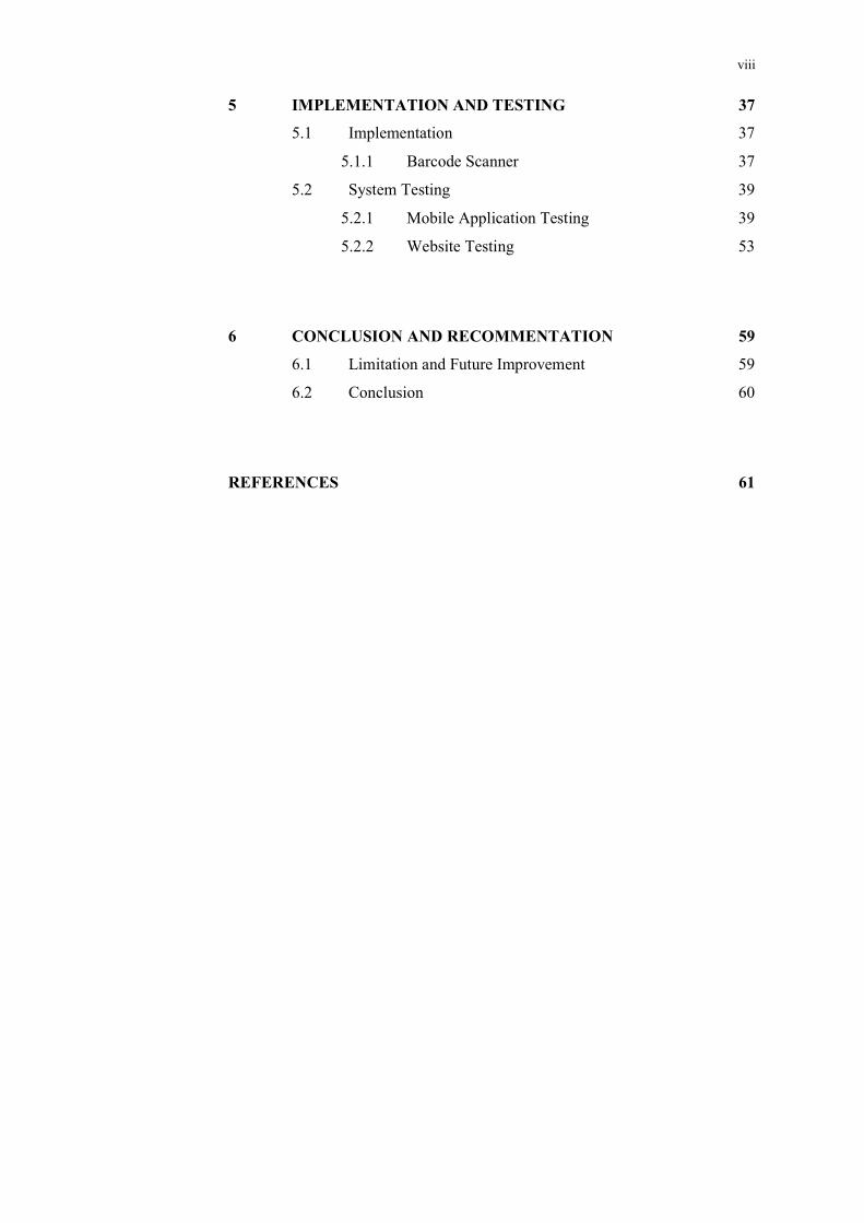
5 IMPLEMENTATION AND TESTING 37
5.1 Implementation 37
5.1.1 Barcode Scanner 37
5.2 System Testing 39
5.2.1 Mobile Application Testing 39
5.2.2 Website Testing 53
6 CONCLUSION AND RECOMMENTATION 59
6.1 Limitation and Future Improvement 59
6.2 Conclusion 60
REFERENCES 61
ix
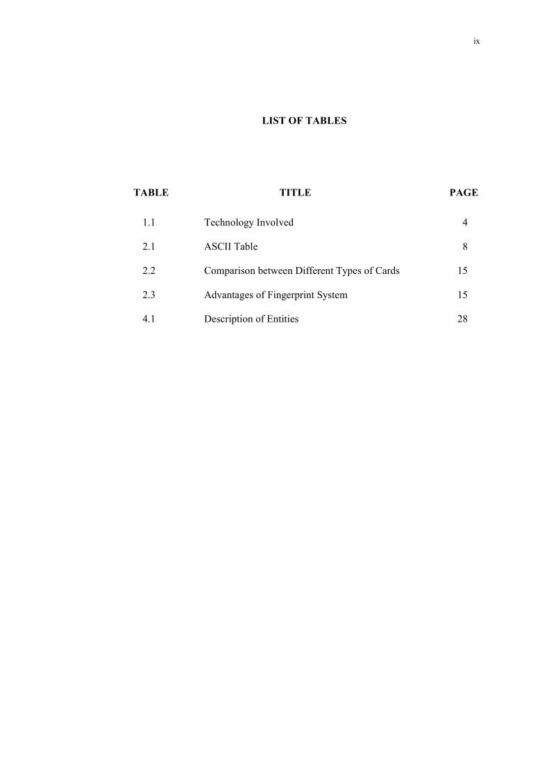
1 LIST OF TABLES
TABLE TITLE PAGE
1.1 Technology Involved 4
2.1 ASCII Table 8
2.2 Comparison between Different Types of Cards 15
2.3 Advantages of Fingerprint System 15
4.1 Description of Entities 28
x
1 LIST OF FIGURES
FIGURE TITLE PAGE
2.1 Student ID Card of UTAR 5
2.2 Result of Barcode Scanner Application 6
2. 3 Linear (1D) Barcode 7
2. 4 Matrix (1D) Barcode 7
2. 5 Punch Card Clock Machine 10
2. 6 System Architecture of Card Reader System 11
2. 7 Proximity Card and Reader 11
2. 8 Contact Smart Card and Reader 12
2. 9 Contactless Smart Card 12
2. 10 Contactless Smart Card Reader 13
2. 11 Magnetic Stripe Card and Reader 13
2. 12 Price Tag with Barcode 13
2. 13 Fingerprint Recognition Attendance Recording Machine 15
2. 14 Summarized Flow of Feature Extraction 16
2. 15 Process Flow of Feature Extraction 16
2. 16 Face Recognition Attendance Recording Machine 17
3.1 Waterfall Model 18
3.2 Prototyping Model 19
xi
3.3 Extreme Programming Process 20
3.4 Rapid Application Development Methodology 21
3.5 Modules of the Project 22
3.6 Work Breakdown Structure 25
3.7 Gantt Chart 25
4.1 System Architecture of the System 26
4.2 Use Case Diagram of the System 27
4.3 ERD of the System 28
4.4 Activity Diagram – Take Attendance 31
4.5 Sequence Diagram – Take Attendance 32
4.6 Activity Diagram – Search and View Attendance 33
4.7 Sequence Diagram – Search and View Attendance 34
4.8 Activity Diagram – Modify Attendance 35
4.9 Sequence Diagram – Modify Attendance 36
5.1 Section of Code – Import ZXing Project 37
5.2 Section of Code – Start Barcode Scanner 38
5.3 Section of Code – Get Scanner Result 38
xii
1 LIST OF ABBREVIATIONS
UTAR University Tunku Abdul Rahman
ID Identification
OS Operating System
XML Extensible Markup Language
1D One-Dimentional
2D Two-Dimentional
DSP Digital Signal Processing
SDK Software Development Kit
RF Radio Frequency
ATM Automated Teller Machine
API Application Programming Interface
SE Software Engineering
XP Extreme Programming
RAD Rapid Application Development
ERD Entity Relationship Diagram
1
CHAPTER 1
1 INTRODUCTION
1.1 Summary
This Student Attendance Recording System is developed for University Tunku
Abdul Rahman (UTAR). This system will provide a mobile application for lecturers
of the university to install and use it during class. The application will allow the users
to record student attendance, and it will automatically update to the server. By using
the application, the student attendance will be updated automatically. The purpose of
this system is to facilitate the lecturer by reducing the manual works needed to record
and update student attendance.
1.2 Problem Statement
In many universities, such as UTAR, student’s attendance is recorded in the manual
way. Lecturers record the student attendance by distributing the name list to students,
and let the students to sign their signature on the name list by themselves. In this case,
a student may help other student to sign. This action can be considered as cheating.
Besides that, updating the student attendance is a manual task. They refer to
the name list to update every single student’s attendance. If the number of student of
a class is large, updating student attendance will takes a lot of time. And also, a
2
lecturer will be assigned to handle at least more than one class. So, a simple task of
updating student attendance record has turned to a tiring and time consuming task.
Furthermore, it will be very troublesome if the lecturer did not bring the name
list to the class or the name list is missing. In this case, lecturer needs to think a way
to record the student attendance. By giving a real life example, if the lecturer did not
bring the name list to the class, he/she will record the attendance by ordering all the
student to write down their name and student ID on a paper.
1.3 Objective
The main purpose of this project is to introduce a new method for UTAR to handle
the task of recording and updating student attendance. The new method has four
objectives need to be achieved:
To provide a mobile application for lecturers to record student attendance.
To provide a mobile application for lecturers to view and modify student
attendance.
To provide a website for admin and lecturers to search, view and modify
student attendance.
To provide a mobile application for students to check their attendance record.
1.4 Project Scope
Modules covered in this project:
1) Lecturer Module:
Lecturers able to use the mobile application to record student attendance.
3
Lecturers able to use the mobile application and website to view student
attendance and attendance percentage.
Lecturers able to use the mobile application and website to modify student
attendance.
Lecturer able to use the website to search student attendance.
2) Student Module:
Student able to use the mobile application to view their attendance of all
enrolled subject.
3) Admin Module
Admin able to use the website to search, view and modify student attendance.
4) Server Module:
Server able to complete client’s requests.
Server able to retrieve data from database.
Server able to update the data in database.
5) Database Module:
Store data of staffs, students, classes, and student attendance.
Due to constraint of time and cost:
System developed is not integrated with system of UTAR.
Data is hardcoded into database.
1.5 Justification
The reason for developing this system is to suggest a new method for UTAR’s
lecturers to record and update student attendance. Besides UTAR, other universities
or colleges such as TARUC (Tunku Abdul Rahman University College), Taylors
4
University, HELP University College, SEGI University College, UCSI University
are still using the same method to record and update the student attendance.
Besides that, this system is also developed to reduce the workloads of
updating the student attendance. Currently, the method used by UTAR is very time-
consuming. The larger class size, the longer time needed to update the student
attendance. It is because the student attendance is updated one-by-one by a single
person.
1.6 Technology Involved
The deliverable of Student Attendance Recording System is an Android application
which will be installed on users’ mobile devices. According to Android official
website, the technologies involved in development are shown in Table 1.1:
Table 1.1: Technology Involved
Hardware 1) Personal computer 2) Mobile phones with Android OS 3) Camera of mobile phones
Software
1) OS: Microsoft Windows, Android 2) Programming Language: Java, XML, PHP, HTML, CSS,
JavaScript (JQuery) 3) Server: Apache Web Server 4) Database: MYSQL Database 5) IDE: Android Studio 6) Web browsers
5
CHAPTER 2
2 LITERATURE REVIEW
2.1 Student ID Card of UTAR
The use of ID card is mainly to verify the identity of the person who holding it.
Universities issue ID card to students so they can use it as a proof to prove that
he/she is a student of the university. Normally, ID card only contains the essential
information such as ID number, name of the person and other identity information.
Figure 2.1 shows the student ID card of UTAR.
Figure 2.1: Student ID Card of UTAR
Student ID card of UTAR contains barcode of student ID number. The
barcode is a 1D barcode, with format CODE 128, and the type of information set is a
simple text. To identify the barcode format and type of information set, users can use
existing scanner application to identify the barcode format and its encode
6
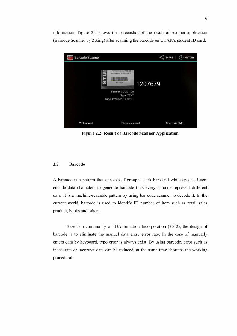
information. Figure 2.2 shows the screenshot of the result of scanner application
(Barcode Scanner by ZXing) after scanning the barcode on UTAR’s student ID card.
Figure 2.2: Result of Barcode Scanner Application
2.2 Barcode
A barcode is a pattern that consists of grouped dark bars and white spaces. Users
encode data characters to generate barcode thus every barcode represent different
data. It is a machine-readable pattern by using bar code scanner to decode it. In the
current world, barcode is used to identify ID number of item such as retail sales
product, books and others.
Based on community of IDAutomation Incorporation (2012), the design of
barcode is to eliminate the manual data entry error rate. In the case of manually
enters data by keyboard, typo error is always exist. By using barcode, error such as
inaccurate or incorrect data can be reduced, at the same time shortens the working
procedural.
7
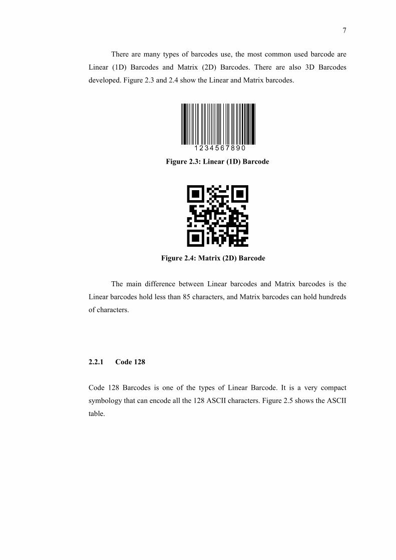
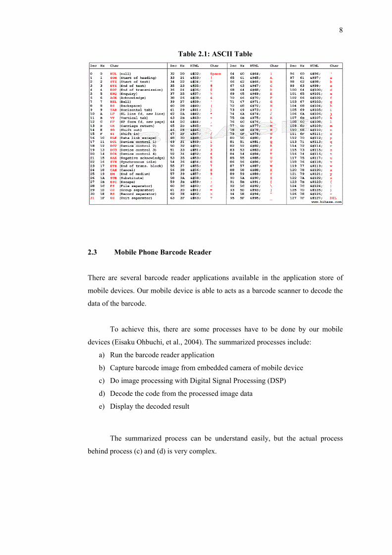
There are many types of barcodes use, the most common used barcode are
Linear (1D) Barcodes and Matrix (2D) Barcodes. There are also 3D Barcodes
developed. Figure 2.3 and 2.4 show the Linear and Matrix barcodes.
Figure 2.3: Linear (1D) Barcode
Figure 2.4: Matrix (2D) Barcode
The main difference between Linear barcodes and Matrix barcodes is the
Linear barcodes hold less than 85 characters, and Matrix barcodes can hold hundreds
of characters.
2.2.1 Code 128
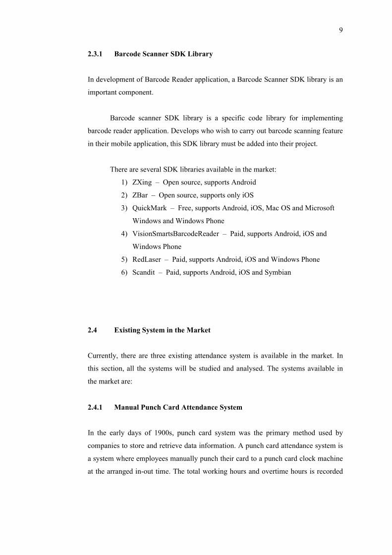
Code 128 Barcodes is one of the types of Linear Barcode. It is a very compact
symbology that can encode all the 128 ASCII characters. Figure 2.5 shows the ASCII
table.
8
Table 2.1: ASCII Table
2.3 Mobile Phone Barcode Reader
There are several barcode reader applications available in the application store of
mobile devices. Our mobile device is able to acts as a barcode scanner to decode the
data of the barcode.
To achieve this, there are some processes have to be done by our mobile
devices (Eisaku Ohbuchi, et al., 2004). The summarized processes include:
a) Run the barcode reader application
b) Capture barcode image from embedded camera of mobile device
c) Do image processing with Digital Signal Processing (DSP)
d) Decode the code from the processed image data
e) Display the decoded result
The summarized process can be understand easily, but the actual process
behind process (c) and (d) is very complex.
9
2.3.1 Barcode Scanner SDK Library
In development of Barcode Reader application, a Barcode Scanner SDK library is an
important component.
Barcode scanner SDK library is a specific code library for implementing
barcode reader application. Develops who wish to carry out barcode scanning feature
in their mobile application, this SDK library must be added into their project.
There are several SDK libraries available in the market:
1) ZXing – Open source, supports Android
2) ZBar – Open source, supports only iOS
3) QuickMark – Free, supports Android, iOS, Mac OS and Microsoft
Windows and Windows Phone
4) VisionSmartsBarcodeReader – Paid, supports Android, iOS and
Windows Phone
5) RedLaser – Paid, supports Android, iOS and Windows Phone
6) Scandit – Paid, supports Android, iOS and Symbian
2.4 Existing System in the Market
Currently, there are three existing attendance system is available in the market. In
this section, all the systems will be studied and analysed. The systems available in
the market are:
2.4.1 Manual Punch Card Attendance System
In the early days of 1900s, punch card system was the primary method used by
companies to store and retrieve data information. A punch card attendance system is
a system where employees manually punch their card to a punch card clock machine
at the arranged in-out time. The total working hours and overtime hours is recorded
10
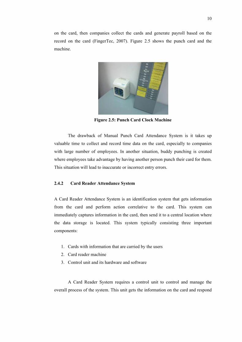
on the card, then companies collect the cards and generate payroll based on the
record on the card (FingerTec, 2007). Figure 2.5 shows the punch card and the
machine.
Figure 2.5: Punch Card Clock Machine
The drawback of Manual Punch Card Attendance System is it takes up
valuable time to collect and record time data on the card, especially to companies
with large number of employees. In another situation, buddy punching is created
where employees take advantage by having another person punch their card for them.
This situation will lead to inaccurate or incorrect entry errors.
2.4.2 Card Reader Attendance System
A Card Reader Attendance System is an identification system that gets information
from the card and perform action correlative to the card. This system can
immediately captures information in the card, then send it to a central location where
the data storage is located. This system typically consisting three important
components:
1. Cards with information that are carried by the users
2. Card reader machine
3. Control unit and its hardware and software
A Card Reader System requires a control unit to control and manage the
overall process of the system. This unit gets the information on the card and respond
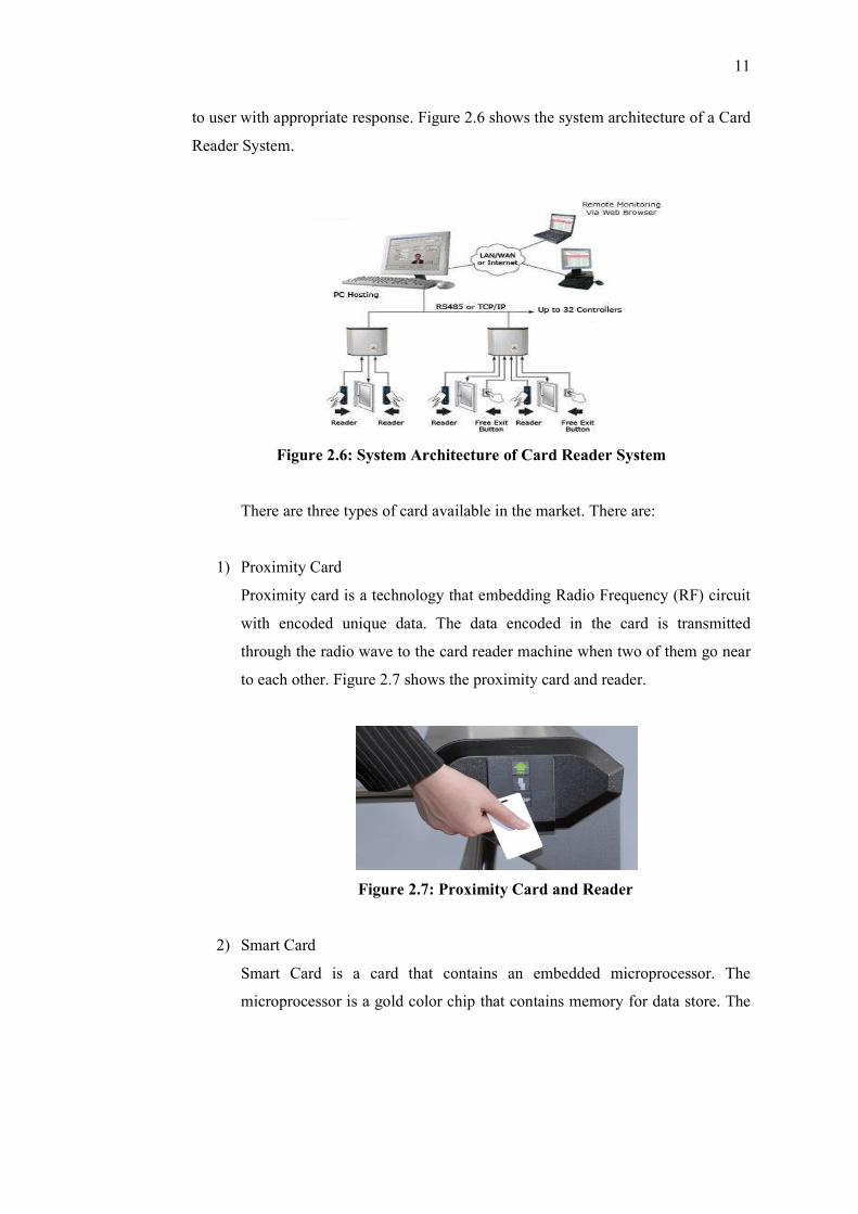
11
to user with appropriate response. Figure 2.6 shows the system architecture of a Card
Reader System.
Figure 2.6: System Architecture of Card Reader System
There are three types of card available in the market. There are:
1) Proximity Card
Proximity card is a technology that embedding Radio Frequency (RF) circuit
with encoded unique data. The data encoded in the card is transmitted
through the radio wave to the card reader machine when two of them go near
to each other. Figure 2.7 shows the proximity card and reader.
Figure 2.7: Proximity Card and Reader
2) Smart Card
Smart Card is a card that contains an embedded microprocessor. The
microprocessor is a gold color chip that contains memory for data store. The
12
chip on the smart card acts as a contact pad, users insert the card into a smart
card reader to read the data. There are two types of smart card:
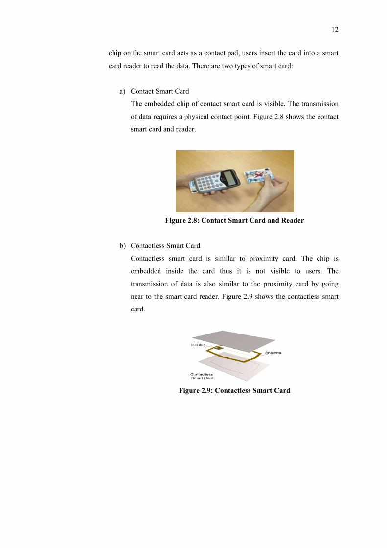
a) Contact Smart Card
The embedded chip of contact smart card is visible. The transmission
of data requires a physical contact point. Figure 2.8 shows the contact
smart card and reader.
Figure 2.8: Contact Smart Card and Reader
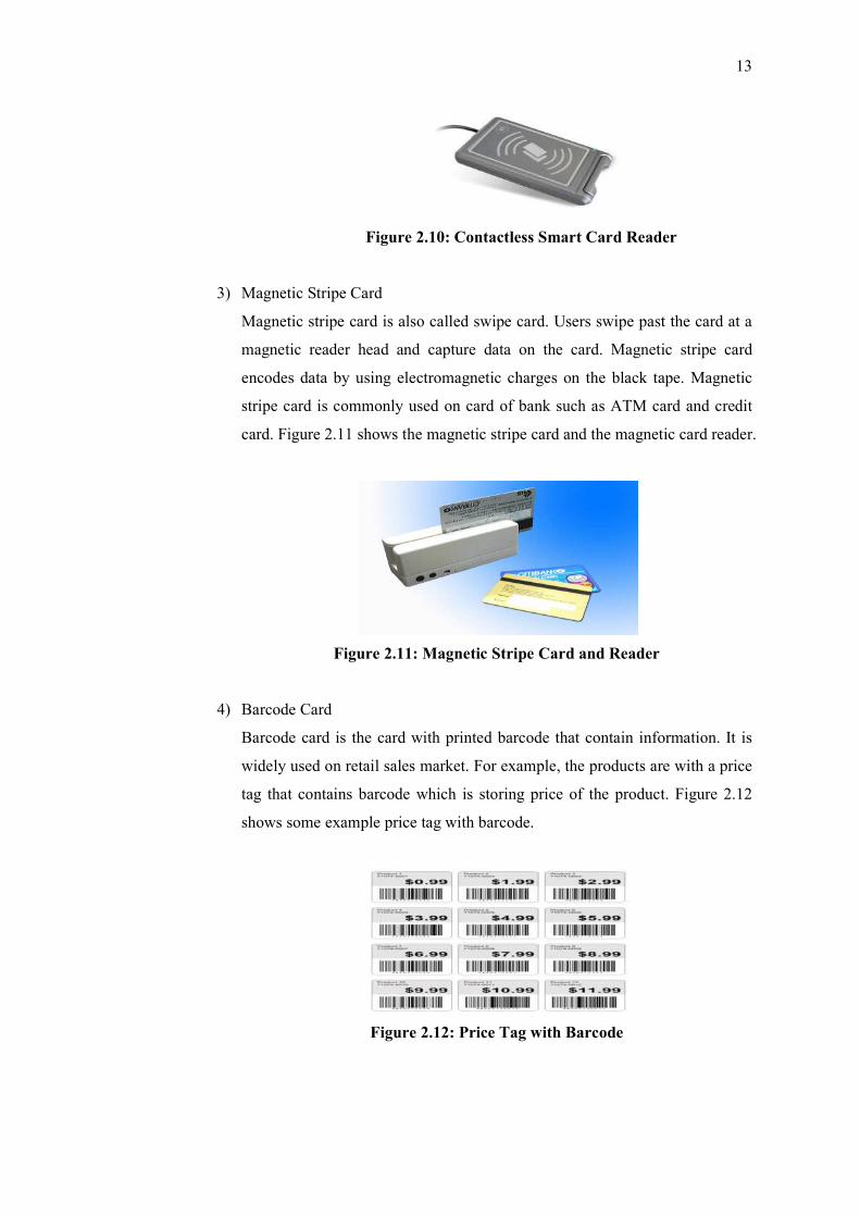
b) Contactless Smart Card
Contactless smart card is similar to proximity card. The chip is
embedded inside the card thus it is not visible to users. The
transmission of data is also similar to the proximity card by going
near to the smart card reader. Figure 2.9 shows the contactless smart
card.
Figure 2.9: Contactless Smart Card
13
Figure 2.10: Contactless Smart Card Reader
3) Magnetic Stripe Card
Magnetic stripe card is also called swipe card. Users swipe past the card at a
magnetic reader head and capture data on the card. Magnetic stripe card
encodes data by using electromagnetic charges on the black tape. Magnetic
stripe card is commonly used on card of bank such as ATM card and credit
card. Figure 2.11 shows the magnetic stripe card and the magnetic card reader.
Figure 2.11: Magnetic Stripe Card and Reader
4) Barcode Card
Barcode card is the card with printed barcode that contain information. It is
widely used on retail sales market. For example, the products are with a price
tag that contains barcode which is storing price of the product. Figure 2.12
shows some example price tag with barcode.
Figure 2.12: Price Tag with Barcode
14
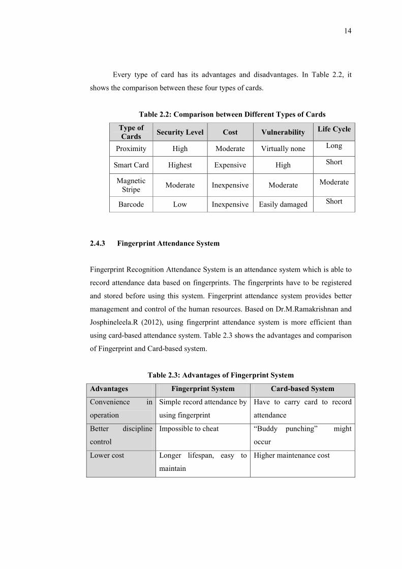
Every type of card has its advantages and disadvantages. In Table 2.2, it
shows the comparison between these four types of cards.
Table 2.2: Comparison between Different Types of Cards
Type of Cards
Security Level Cost Vulnerability Life Cycle
Proximity High Moderate Virtually none Long
Smart Card Highest Expensive High Short
Magnetic Stripe
Moderate Inexpensive Moderate Moderate
Barcode Low Inexpensive Easily damaged Short
2.4.3 Fingerprint Attendance System
Fingerprint Recognition Attendance System is an attendance system which is able to
record attendance data based on fingerprints. The fingerprints have to be registered
and stored before using this system. Fingerprint attendance system provides better
management and control of the human resources. Based on Dr.M.Ramakrishnan and
Josphineleela.R (2012), using fingerprint attendance system is more efficient than
using card-based attendance system. Table 2.3 shows the advantages and comparison
of Fingerprint and Card-based system.
Table 2.3: Advantages of Fingerprint System
Advantages Fingerprint System Card-based System
Convenience in
operation
Simple record attendance by
using fingerprint
Have to carry card to record
attendance
Better discipline
control
Impossible to cheat “Buddy punching” might
occur
Lower cost Longer lifespan, easy to
maintain
Higher maintenance cost
15
Flexible
deployment
Only consists of light
weight machine
Space required for keeping
cards
Reduce workloads Automatic storing data once
it is captured
Manually input data by
referring to the cards
Better data
management
Information is ready most of
the time because it is stored
immediately after captured
Data entry task have to be done
first before using the data
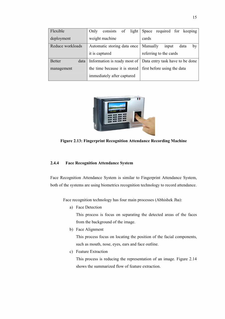
Figure 2.13: Fingerprint Recognition Attendance Recording Machine
2.4.4 Face Recognition Attendance System
Face Recognition Attendance System is similar to Fingerprint Attendance System,
both of the systems are using biometrics recognition technology to record attendance.
Face recognition technology has four main processes (Abhishek Jha):
a) Face Detection
This process is focus on separating the detected areas of the faces
from the background of the image.
b) Face Alignment
This process focus on locating the position of the facial components,
such as mouth, nose, eyes, ears and face outline.
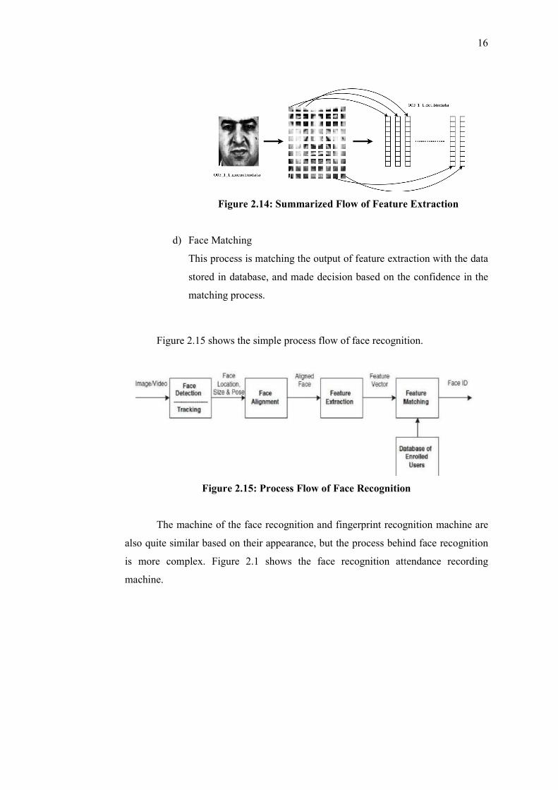
c) Feature Extraction
This process is reducing the representation of an image. Figure 2.14
shows the summarized flow of feature extraction.
d) Face Matching
This process is matching the output of feature extraction with the data
stored in database, and made decision based on the confidence in the
matching process.
Figure 2.15 shows the simple process flow of face recognition.
Figure 2.15:
The machine of the face recognition and fingerprint recognition machine
also quite similar based on their appearance, but the process behind face recognition
is more complex. Figure 2.1 shows the face recognition atte
machine.
Figure 2.14: Summarized Flow of Feature Extraction
Matching
This process is matching the output of feature extraction with the data
stored in database, and made decision based on the confidence in the
matching process.
Figure 2.15 shows the simple process flow of face recognition.
Figure 2.15: Process Flow of Face Recognition
The machine of the face recognition and fingerprint recognition machine
also quite similar based on their appearance, but the process behind face recognition
is more complex. Figure 2.1 shows the face recognition atte
16
Feature Extraction
This process is matching the output of feature extraction with the data
stored in database, and made decision based on the confidence in the
Figure 2.15 shows the simple process flow of face recognition.
Process Flow of Face Recognition
The machine of the face recognition and fingerprint recognition machine are
also quite similar based on their appearance, but the process behind face recognition
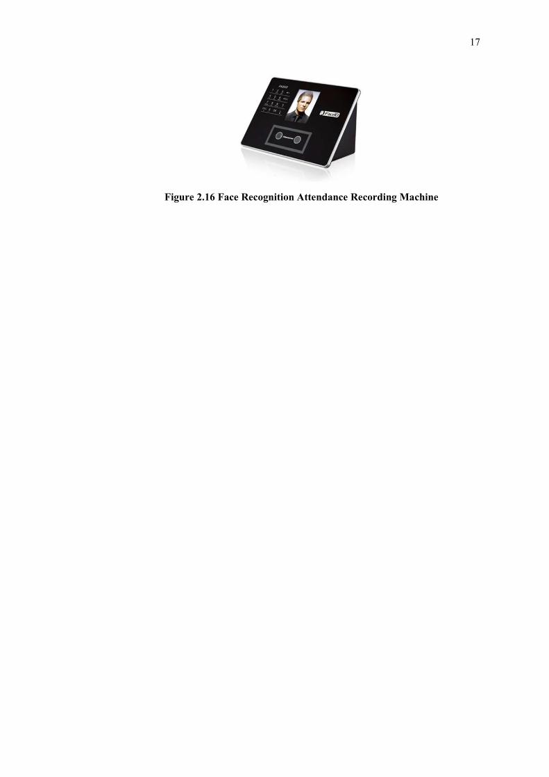
is more complex. Figure 2.1 shows the face recognition attendance recording
17
Figure 2.16 Face Recognition Attendance Recording Machine
18
CHAPTER 3
3 METHODOLOGY
3.1 Development Methodology
There are several software development methodology introduced on the field. In this
section, several development models will be described, and one of the development
method described will be chosen as adopted methodology of this project.
3.1.1 Waterfall Model
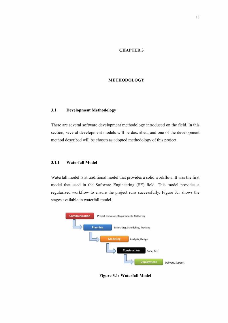
Waterfall model is at traditional model that provides a solid workflow. It was the first
model that used in the Software Engineering (SE) field. This model provides a
regularized workflow to ensure the project runs successfully. Figure 3.1 shows the
stages available in waterfall model.
Figure 3.1: Waterfall Model
19
Waterfall model proposes a sequential development process which is
following the rigid model shown in Figure 3.1. It has the advantage that this model is
simple and straightforward and easy to understand. It is also easy to management
because of the rigid workflow.
The disadvantage about waterfall model is also because of its development
process. It is not suitable for software development where the change of requirement
is unavoidable. Waterfall model is suitable when requirements are well planned and
fixed.
3.1.2 Prototyping Model
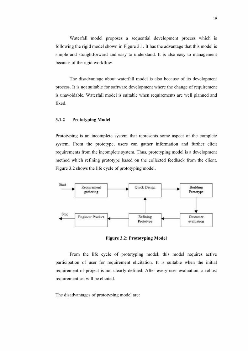
Prototyping is an incomplete system that represents some aspect of the complete
system. From the prototype, users can gather information and further elicit
requirements from the incomplete system. Thus, prototyping model is a development
method which refining prototype based on the collected feedback from the client.
Figure 3.2 shows the life cycle of prototyping model.
Figure 3.2: Prototyping Model
From the life cycle of prototyping model, this model requires active
participation of user for requirement elicitation. It is suitable when the initial
requirement of project is not clearly defined. After every user evaluation, a robust
requirement set will be elicited.
The disadvantages of prototyping model are:
a) Customer expecting fast completion because they might assume the prototype
as final product
b) High involvement of user resulting
3.1.3 Extreme Programming (XP)
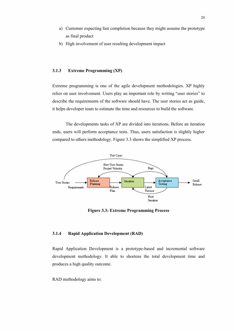
Extreme programming is one
relies on user involvement. Users play an important role by writing “user stories” to
describe the requirements of the software should have. The user stories act as
it helps developer team to estimat
The developments tasks of XP are divided
ends, users will perform acceptance tests. Thus, users satisfaction is slightly higher
compared to others methodology
Figure 3.3: Extreme Programming
3.1.4 Rapid Application Development (RAD)
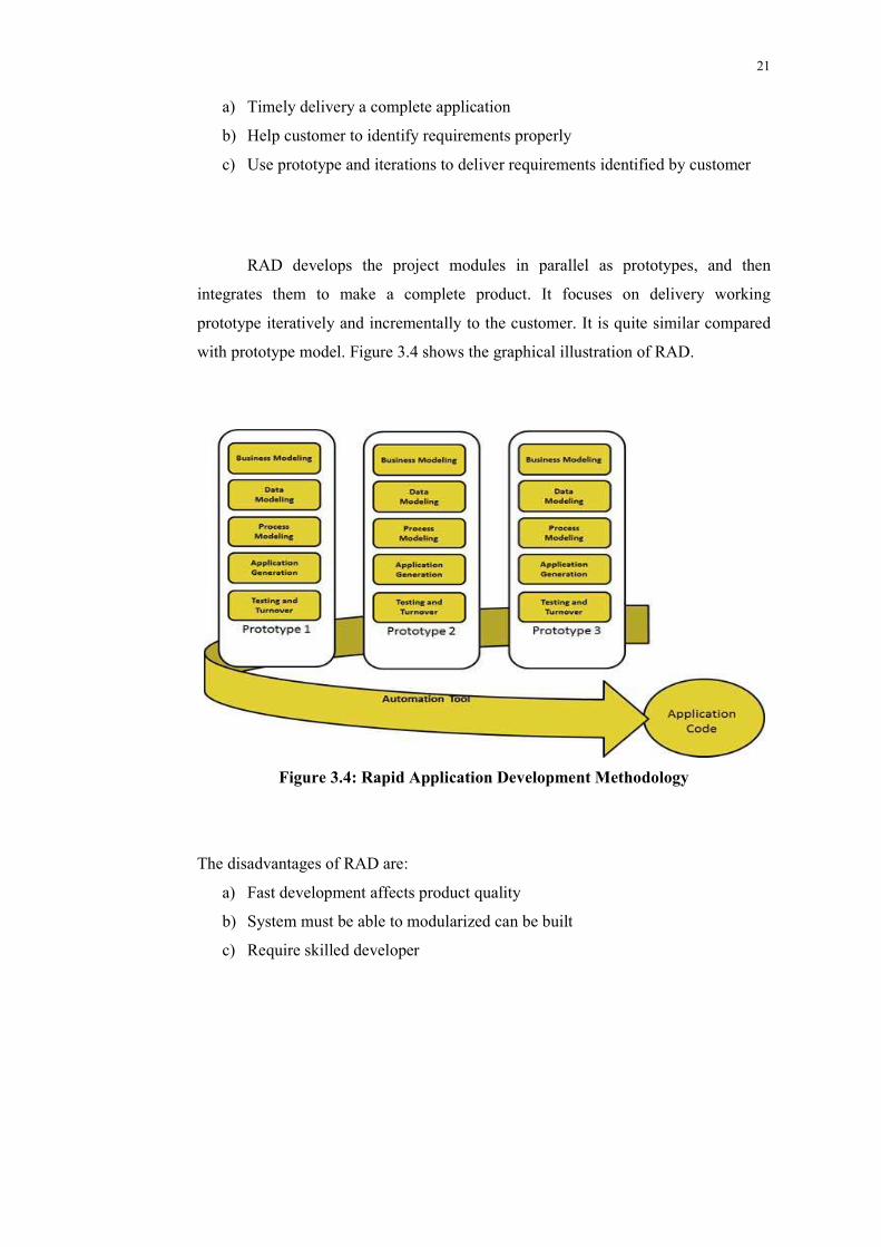
Rapid Application Development is
development methodology. It able to shortens the total development time and
produces a high quality outcome
RAD methodology aims to:
Customer expecting fast completion because they might assume the prototype
as final product
High involvement of user resulting development impact
Extreme Programming (XP)
Extreme programming is one of the agile development methodologies. XP highly
relies on user involvement. Users play an important role by writing “user stories” to
describe the requirements of the software should have. The user stories act as
developer team to estimate the time and resources to build the software.
The developments tasks of XP are divided into iterations. Before an iteration
ends, users will perform acceptance tests. Thus, users satisfaction is slightly higher
compared to others methodology. Figure 3.3 shows the simplified XP process.
Figure 3.3: Extreme Programming Process
Rapid Application Development (RAD)
Rapid Application Development is a prototype-based and incremental
development methodology. It able to shortens the total development time and
high quality outcome.
RAD methodology aims to:
20
Customer expecting fast completion because they might assume the prototype
of the agile development methodologies. XP highly
relies on user involvement. Users play an important role by writing “user stories” to
describe the requirements of the software should have. The user stories act as guide,
e the time and resources to build the software.
to iterations. Before an iteration
ends, users will perform acceptance tests. Thus, users satisfaction is slightly higher
.3 shows the simplified XP process.
incremental software
development methodology. It able to shortens the total development time and
21
a) Timely delivery a complete application
b) Help customer to identify requirements properly
c) Use prototype and iterations to deliver requirements identified by customer
RAD develops the project modules in parallel as prototypes, and then
integrates them to make a complete product. It focuses on delivery working
prototype iteratively and incrementally to the customer. It is quite similar compared
with prototype model. Figure 3.4 shows the graphical illustration of RAD.
Figure 3.4: Rapid Application Development Methodology
The disadvantages of RAD are:
a) Fast development affects product quality
b) System must be able to modularized can be built
c) Require skilled developer
3.2 Adopted Development Methodology
After studied and analyzed all four development methodologies, Rapid Application
Development is the most suitable methodology for this project. The reasons are:
1) Duration for development of this project is
process for project development duration has to be consider
2) The foundation r
planning and analysis stage.
3) Project can be modularized
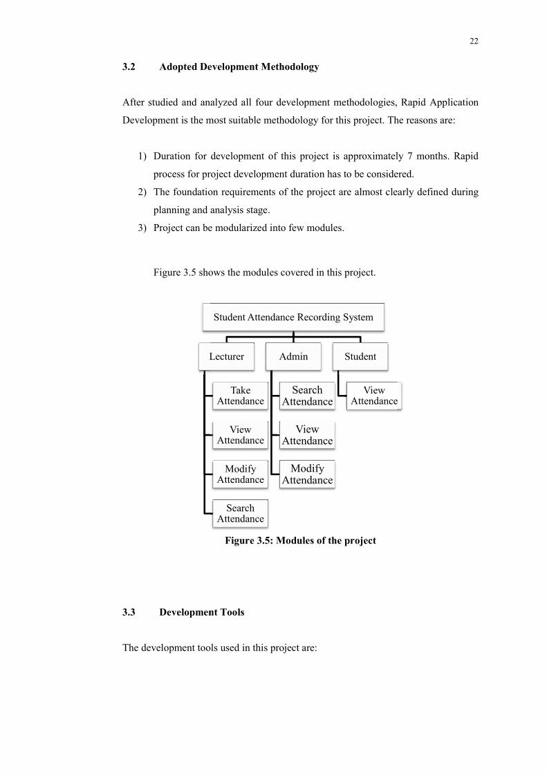
Figure 3.5 shows the modules covered in this project.
3.3 Development Tools
The development tools used in this project are:
Lecturer
Adopted Development Methodology
After studied and analyzed all four development methodologies, Rapid Application
Development is the most suitable methodology for this project. The reasons are:
Duration for development of this project is approximately 7 months
process for project development duration has to be consider
The foundation requirements of the project are almost clearly defined
planning and analysis stage.
e modularized into few modules.
Figure 3.5 shows the modules covered in this project.
Figure 3.5: Modules of the project
Development Tools
The development tools used in this project are:
Student Attendance Recording System
Lecturer
Take Attendance
View Attendance
Modify Attendance
Search Attendance
Admin
Search Attendance
View Attendance
Modify Attendance
Student
View Attendance
22
After studied and analyzed all four development methodologies, Rapid Application
Development is the most suitable methodology for this project. The reasons are:
approximately 7 months. Rapid
process for project development duration has to be considered.
are almost clearly defined during
Attendance
23
1. Android Studio
Android Studio is the official IDE for Android development. It provides
everything needed to start developing an Android project. In this project,
Android Studio will be used to create the mobile application.
2. Notepad++
Notepad++ is an open source code editor software. It is an advanced version
of notepad. Notepad++ supports many programming languages and syntax.
Notepad++ will be used to write and edit code such as PHP, HTML, CSS and
JavaScript.
3. WampServer
WampServer is a web development environment for Windows. It provides a
set of features to developer which is including Apache web server, MySQL
database and PHP server-side scripting. By using WampServer in this project,
developer able to:
Create a localhost server with the Apache
Manage database with phpMyAdmin
3.4 Project Plan
3.4.1 Project Breakdown
The development of the system will be divided into six main phases:
1. Planning
Research on the problem statement and objectives
Define problem statement of the project
Define objective(s) of the project
24
Determine scope of the system
2. Analysis
Literature reviewing
Analyzing methodologies to be used
Writing complete proposal of the project
3. Design
Designing architecture of the system
Designing the functions to be implemented
Designing database
Designing user interface of the application
Reviewing design
Refining design
4. Implementation
Implementing server-side coding
Implementing client-side application coding
5. Testing
Developing test plan
Unit Testing
System Testing
User Acceptance Testing
Modify and refining code
6. Deployment
Distributing applications to user
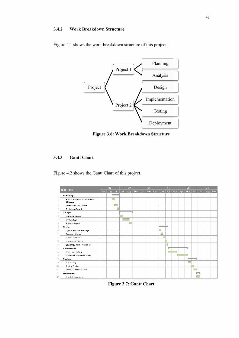
3.4.2 Work Breakdown Structure
Figure 4.1 shows the work breakdown structure of this project.
3.4.3 Gantt Chart
Figure 4.2 shows the Gantt Chart of this project.
Project
Work Breakdown Structure
Figure 4.1 shows the work breakdown structure of this project.
Figure 3.6: Work Breakdown Structure
Gantt Chart
4.2 shows the Gantt Chart of this project.
Figure 3.7: Gantt Chart
Project
Project 1
Planning
Analysis
Project 2
Design
Implementation
Testing
Deployment
25
Implementation
26
CHAPTER 4
4 SYSTEM DESIGN
4.1 System Architecture
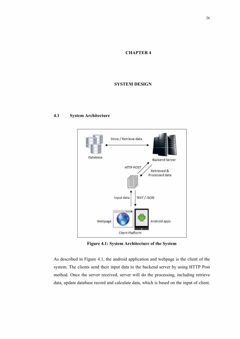
Figure 4.1: System Architecture of the System
As described in Figure 4.1, the android application and webpage is the client of the
system. The clients send their input data to the backend server by using HTTP Post
method. Once the server received, server will do the processing, including retrieve
data, update database record and calculate data, which is based on the input of client.
27
After finish processing, the result will be sent back to the client platform in format of
plain text or JSON.
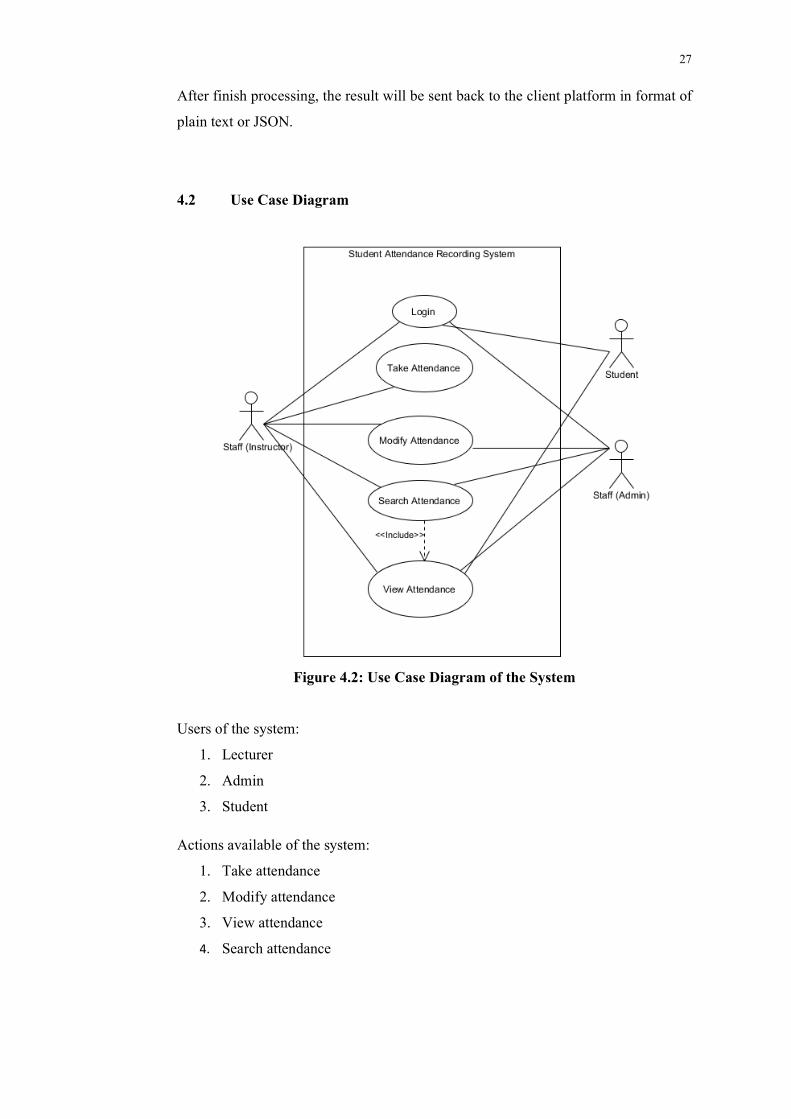
4.2 Use Case Diagram
Figure 4.2: Use Case Diagram of the System
Users of the system:
1. Lecturer
2. Admin
3. Student
Actions available of the system:
1. Take attendance
2. Modify attendance
3. View attendance
4. Search attendance
28
4.3 Database Design
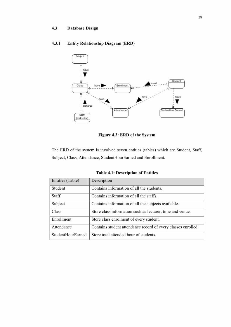
4.3.1 Entity Relationship Diagram (ERD)
Figure 4.3: ERD of the System
The ERD of the system is involved seven entities (tables) which are Student, Staff,
Subject, Class, Attendance, StudentHourEarned and Enrollment.
Table 4.1: Description of Entities
Entities (Table) Description
Student Contains information of all the students.
Staff Contains information of all the staffs.
Subject Contains information of all the subjects available.
Class Store class information such as lecturer, time and venue.
Enrollment Store class enrolment of every student.
Attendance Contains student attendance record of every classes enrolled.
StudentHourEarned Store total attended hour of students.
29
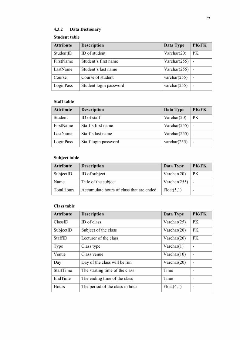
4.3.2 Data Dictionary
Student table
Attribute Description Data Type PK/FK
StudentID ID of student Varchar(20) PK
FirstName Student’s first name Varchar(255) -
LastName Student’s last name Varchar(255) -
Course Course of student varchar(255) -
LoginPass Student login password varchar(255) -
Staff table
Attribute Description Data Type PK/FK
Student ID of staff Varchar(20) PK
FirstName Staff’s first name Varchar(255) -
LastName Staff’s last name Varchar(255) -
LoginPass Staff login password varchar(255) -
Subject table
Attribute Description Data Type PK/FK
SubjectID ID of subject Varchar(20) PK
Name Title of the subject Varchar(255) -
TotalHours Accumulate hours of class that are ended Float(5,1) -
Class table
Attribute Description Data Type PK/FK
ClassID ID of class Varchar(25) PK
SubjectID Subject of the class Varchar(20) FK
StaffID Lecturer of the class Varchar(20) FK
Type Class type Varchar(1) -
Venue Class venue Varchar(10) -
Day Day of the class will be run Varchar(20) -
StartTime The starting time of the class Time -
EndTime The ending time of the class Time -
Hours The period of the class in hour Float(4,1) -
30
Enrollment table
Attribute Description Data Type PK/FK
EnrollmentID ID of enrolment Integer(11) PK
StudentID Student ID of this enrollment Varchar(20) FK
ClassID Class ID of this enrollment Varchar(20) FK
Attendance table
Attribute Description Data Type PK/FK
AttendanceID ID of attendance Integer(20) PK
Date Date of this attendance Date -
ClassID Class ID of this attendance Varchar(20) FK
StudentID Student ID of this attendance Varchar(20) FK
Attendance Attendance status Varchar(5) -
Hours The period of the class in hours Float(3,1) -
StudentHourEarned table
Attribute Description Data Type PK/FK
ID ID of this table Integer(11) PK
StudentID ID of student of this record Varchar(20) FK
SubjectID ID of subject of this record Varchar(20) FK
HoursEarned The student’s total attended hours of the
subject
Float(5,1) -
NcHours The not counted hours of student in this
subject
Float(4,1) -
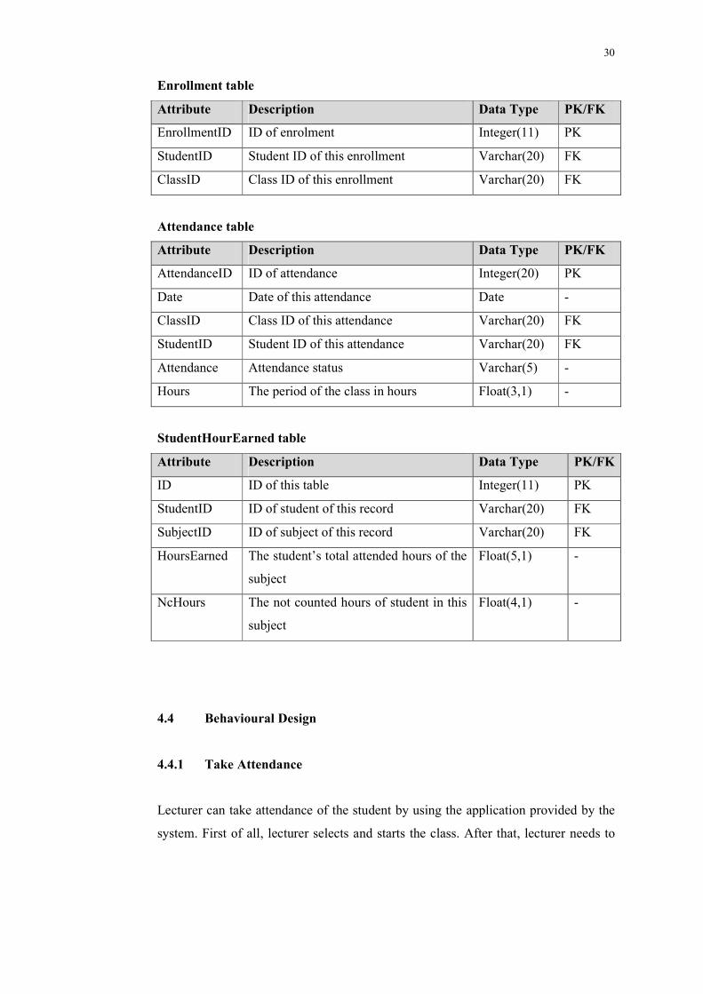
4.4 Behavioural Design
4.4.1 Take Attendance
Lecturer can take attendance of the student by using the application provided by the
system. First of all, lecturer selects and starts the class. After that, lecturer needs to
31
get the student ID to take attendance. To get the student ID, lecturer needs to activate
the integrated scanner application and scan the barcode on the student ID card. After
capture the ID, application will validate the ID then send it to the server and process
it.
Figure 4.4: Activity Diagram – Take Attendance
Diagram above have shown the activity involved to take student attendance
and its process flow. There are including few checking activity to ensure the
attendance record will be updated correctly.
32
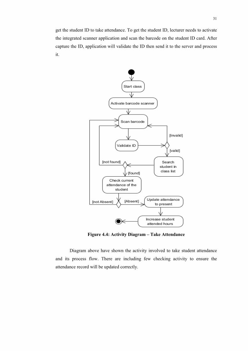
Figure 4.5: Sequence Diagram – Take Attendance
Diagram above has shown the interaction between each components and what
the task done by every component to take attendance.
1) Lecturer uses the application to start the selected class to take attendance.
2) Lecturer activates the barcode scanner application and scans the ID barcode
on student ID card to get their ID number.
3) Barcode scanner application captures the ID number and send back to the
system application.
4) Application validates the captured ID number. If the format of ID number is
valid, it will be sent to the server.
5) Server will search over the database to validate the student ID received from
the application. If the student ID number is valid, server will update the
attendance record and increase student attended hours.
6) Server sends the result back to the application.
4.4.2 Search and View Attendance
Search attendance is a task that every user will involve at. The search result is
depends on the input that sent to the server. When user has logged in, or user has
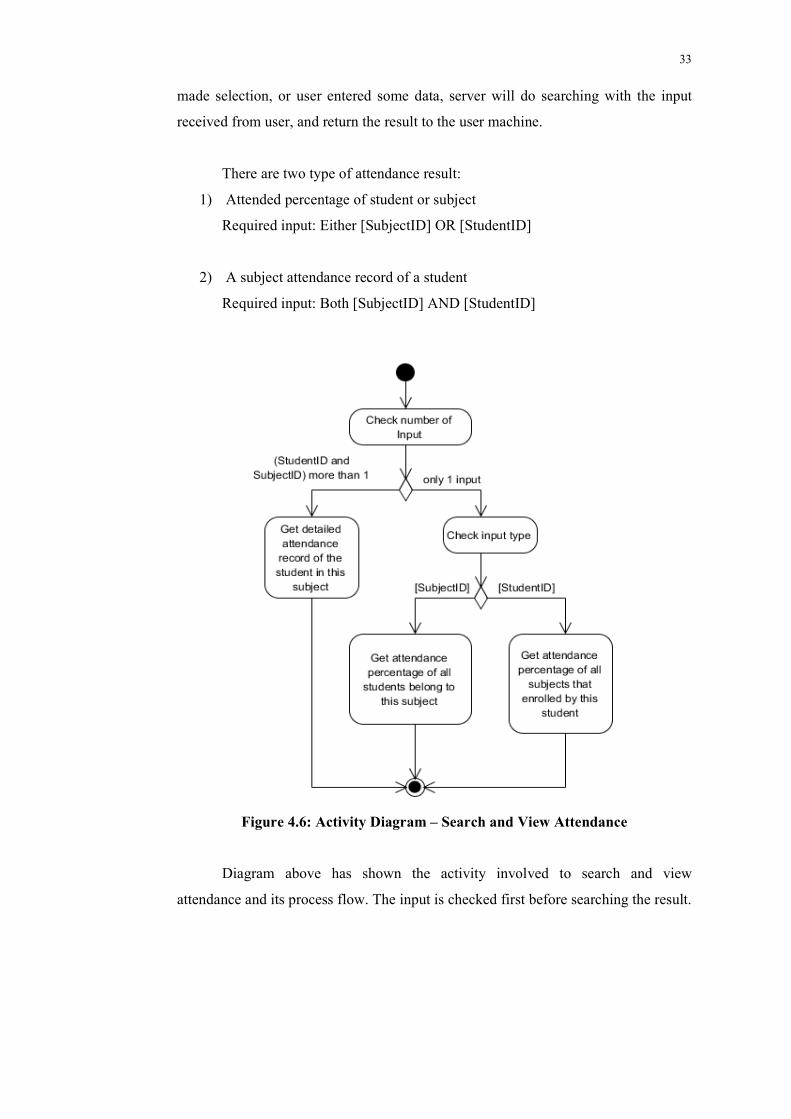
33
made selection, or user entered some data, server will do searching with the input
received from user, and return the result to the user machine.
There are two type of attendance result:
1) Attended percentage of student or subject
Required input: Either [SubjectID] OR [StudentID]
2) A subject attendance record of a student
Required input: Both [SubjectID] AND [StudentID]
Figure 4.6: Activity Diagram – Search and View Attendance
Diagram above has shown the activity involved to search and view
attendance and its process flow. The input is checked first before searching the result.
34
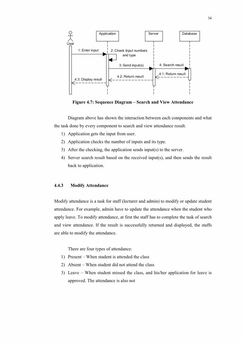
Figure 4.7: Sequence Diagram – Search and View Attendance
Diagram above has shown the interaction between each components and what
the task done by every component to search and view attendance result.
1) Application gets the input from user.
2) Application checks the number of inputs and its type.
3) After the checking, the application sends input(s) to the server.
4) Server search result based on the received input(s), and then sends the result
back to application.
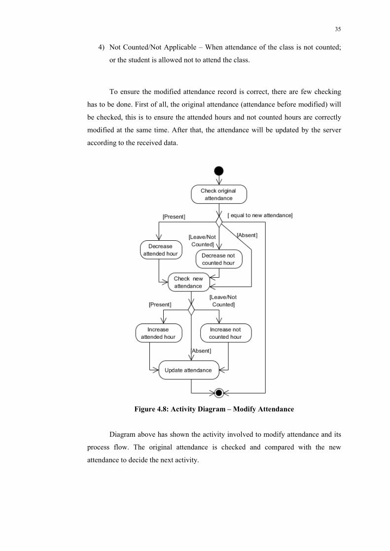
4.4.3 Modify Attendance
Modify attendance is a task for staff (lecturer and admin) to modify or update student
attendance. For example, admin have to update the attendance when the student who
apply leave. To modify attendance, at first the staff has to complete the task of search
and view attendance. If the result is successfully returned and displayed, the staffs
are able to modify the attendance.
There are four types of attendance:
1) Present – When student is attended the class
2) Absent – When student did not attend the class
3) Leave – When student missed the class, and his/her application for leave is
approved. The attendance is also not
35
4) Not Counted/Not Applicable – When attendance of the class is not counted;
or the student is allowed not to attend the class.
To ensure the modified attendance record is correct, there are few checking
has to be done. First of all, the original attendance (attendance before modified) will
be checked, this is to ensure the attended hours and not counted hours are correctly
modified at the same time. After that, the attendance will be updated by the server
according to the received data.
Figure 4.8: Activity Diagram – Modify Attendance
Diagram above has shown the activity involved to modify attendance and its
process flow. The original attendance is checked and compared with the new
attendance to decide the next activity.
36
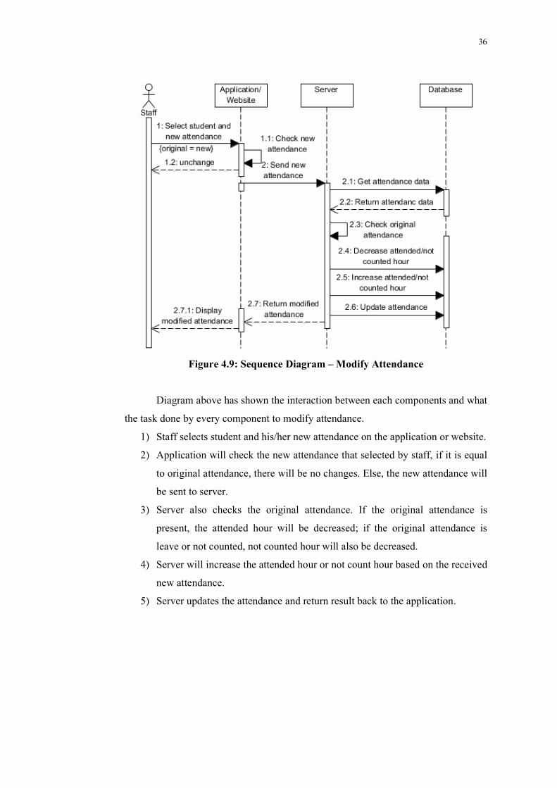
Figure 4.9: Sequence Diagram – Modify Attendance
Diagram above has shown the interaction between each components and what
the task done by every component to modify attendance.
1) Staff selects student and his/her new attendance on the application or website.
2) Application will check the new attendance that selected by staff, if it is equal
to original attendance, there will be no changes. Else, the new attendance will
be sent to server.
3) Server also checks the original attendance. If the original attendance is
present, the attended hour will be decreased; if the original attendance is
leave or not counted, not counted hour will also be decreased.
4) Server will increase the attended hour or not count hour based on the received
new attendance.
5) Server updates the attendance and return result back to the application.
37
CHAPTER 5
5 IMPLEMENTATION AND TESTING
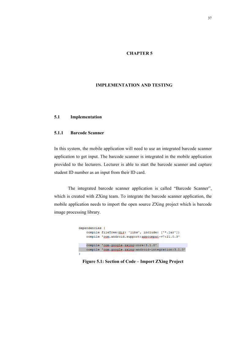
5.1 Implementation
5.1.1 Barcode Scanner
In this system, the mobile application will need to use an integrated barcode scanner
application to get input. The barcode scanner is integrated in the mobile application
provided to the lecturers. Lecturer is able to start the barcode scanner and capture
student ID number as an input from their ID card.
The integrated barcode scanner application is called “Barcode Scanner”,
which is created with ZXing team. To integrate the barcode scanner application, the
mobile application needs to import the open source ZXing project which is barcode
image processing library.
Figure 5.1: Section of Code – Import ZXing Project
38
From Figure 5.1, the highlighted part is the Gradle code to import ZXing
project. The mobile application is able to use the API of ZXing to use the barcode
scanner application.
Figure 5.2: Section of Code – Start Barcode Scanner
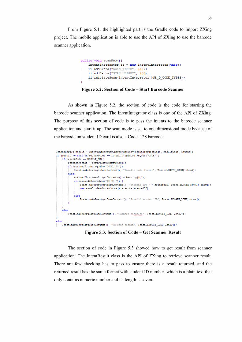
As shown in Figure 5.2, the section of code is the code for starting the
barcode scanner application. The IntentIntegrator class is one of the API of ZXing.
The purpose of this section of code is to pass the intents to the barcode scanner
application and start it up. The scan mode is set to one dimensional mode because of
the barcode on student ID card is also a Code_128 barcode.
Figure 5.3: Section of Code – Get Scanner Result
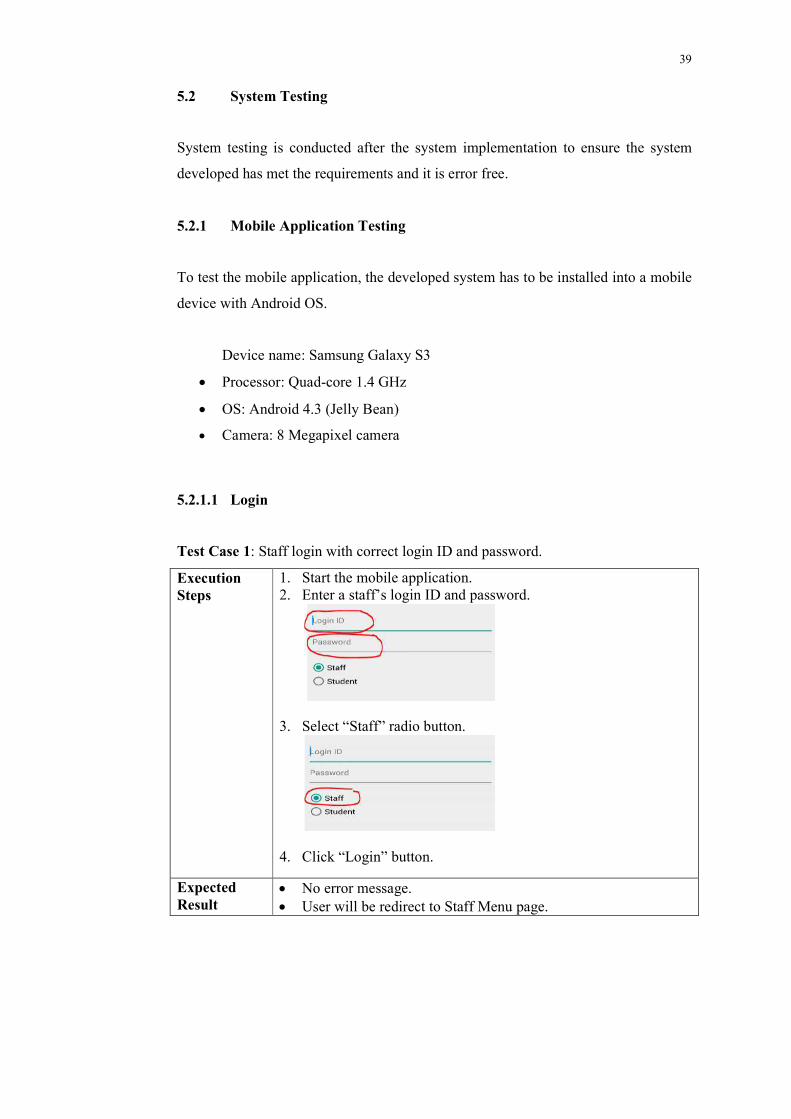
The section of code in Figure 5.3 showed how to get result from scanner
application. The IntentResult class is the API of ZXing to retrieve scanner result.
There are few checking has to pass to ensure there is a result returned, and the
returned result has the same format with student ID number, which is a plain text that
only contains numeric number and its length is seven.
39
5.2 System Testing
System testing is conducted after the system implementation to ensure the system
developed has met the requirements and it is error free.
5.2.1 Mobile Application Testing
To test the mobile application, the developed system has to be installed into a mobile
device with Android OS.
Device name: Samsung Galaxy S3
Processor: Quad-core 1.4 GHz
OS: Android 4.3 (Jelly Bean)
Camera: 8 Megapixel camera
5.2.1.1 Login
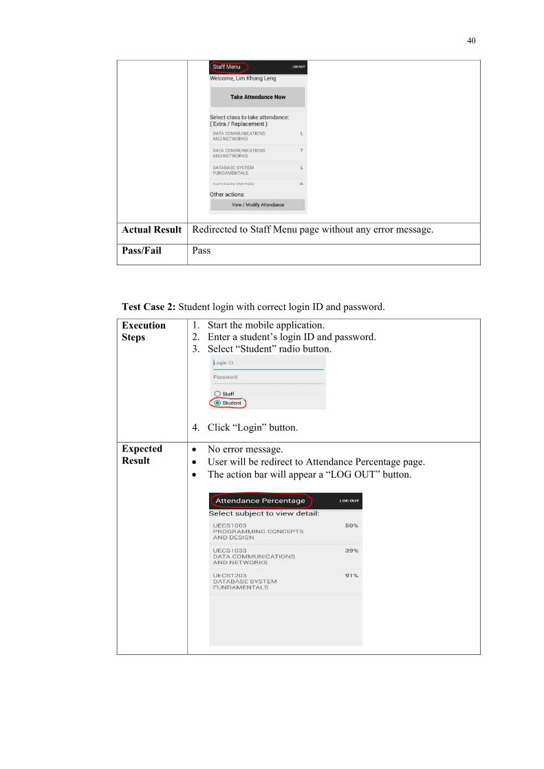
Test Case 1: Staff login with correct login ID and password.
Execution Steps
1. Start the mobile application. 2. Enter a staff’s login ID and password.
3. Select “Staff” radio button.
4. Click “Login” button.
Expected Result
No error message. User will be redirect to Staff Menu page.
40
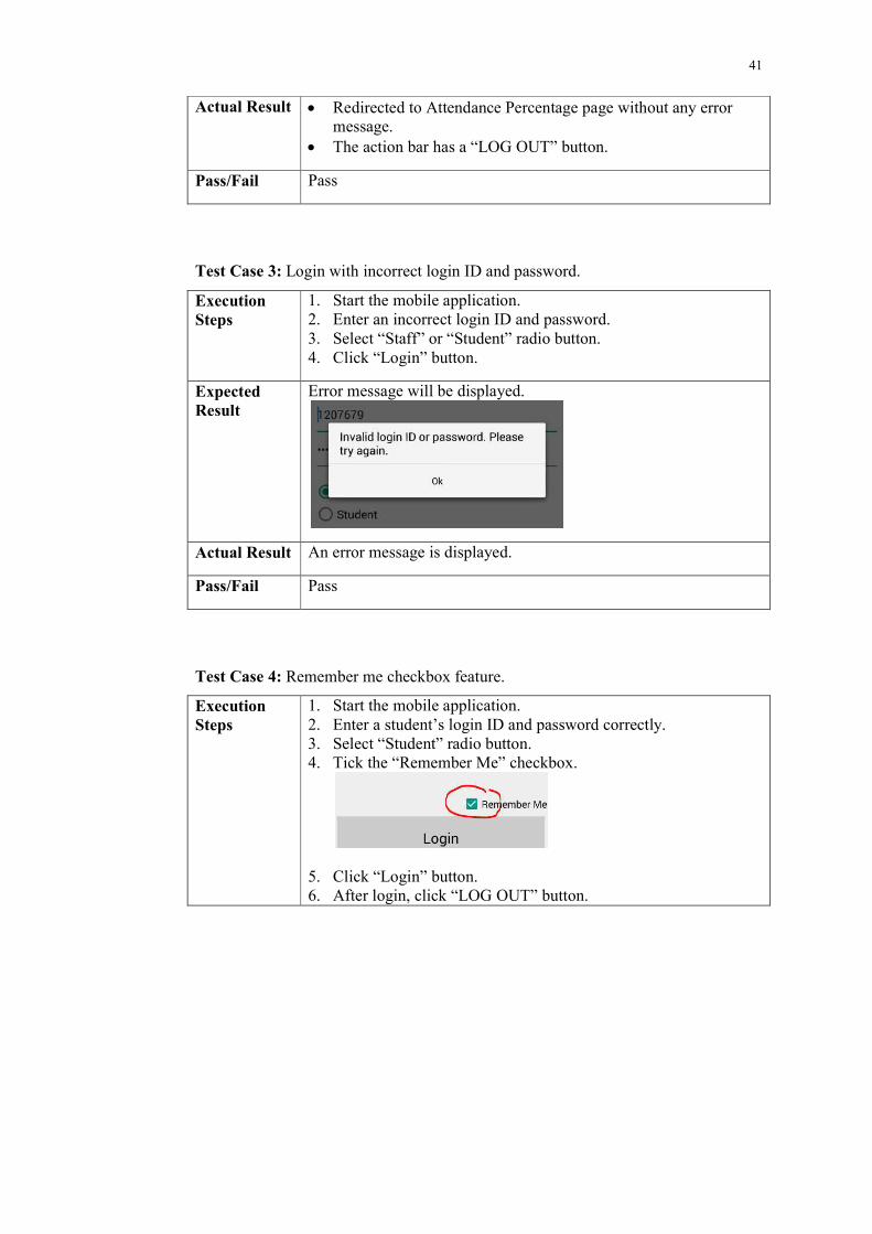
Actual Result Redirected to Staff Menu page without any error message.
Pass/Fail Pass
Test Case 2: Student login with correct login ID and password.
Execution Steps
1. Start the mobile application. 2. Enter a student’s login ID and password. 3. Select “Student” radio button.
4. Click “Login” button.
Expected Result
No error message. User will be redirect to Attendance Percentage page. The action bar will appear a “LOG OUT” button.
41
Actual Result Redirected to Attendance Percentage page without any error message.
The action bar has a “LOG OUT” button.
Pass/Fail Pass
Test Case 3: Login with incorrect login ID and password.
Execution Steps
1. Start the mobile application. 2. Enter an incorrect login ID and password. 3. Select “Staff” or “Student” radio button. 4. Click “Login” button.
Expected Result
Error message will be displayed.
Actual Result An error message is displayed.
Pass/Fail Pass
Test Case 4: Remember me checkbox feature.
Execution Steps
1. Start the mobile application. 2. Enter a student’s login ID and password correctly. 3. Select “Student” radio button. 4. Tick the “Remember Me” checkbox.
5. Click “Login” button. 6. After login, click “LOG OUT” button.
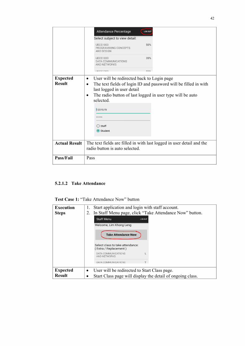
42
Expected Result
User will be redirected back to Login page The text fields of login ID and password will be filled in with
last logged in user detail The radio button of last logged in user type will be auto
selected.
Actual Result The text fields are filled in with last logged in user detail and the radio button is auto selected.
Pass/Fail Pass
5.2.1.2 Take Attendance
Test Case 1: “Take Attendance Now” button
Execution Steps
1. Start application and login with staff account. 2. In Staff Menu page, click “Take Attendance Now” button.
Expected Result
User will be redirected to Start Class page. Start Class page will display the detail of ongoing class.
43
Actual Result User is redirected to Start Class page, and the page is displaying the correct ongoing class detail.
Pass/Fail Pass
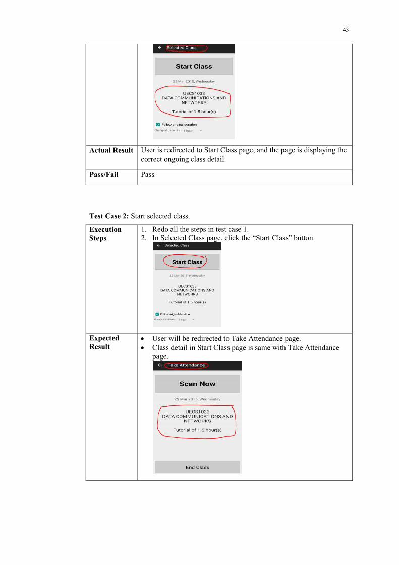
Test Case 2: Start selected class.
Execution Steps
1. Redo all the steps in test case 1. 2. In Selected Class page, click the “Start Class” button.
Expected Result
User will be redirected to Take Attendance page. Class detail in Start Class page is same with Take Attendance
page.
44
Actual Result User is redirected to Take Attendance page, and the displayed class detail is same with Selected Class page.
Pass/Fail Pass
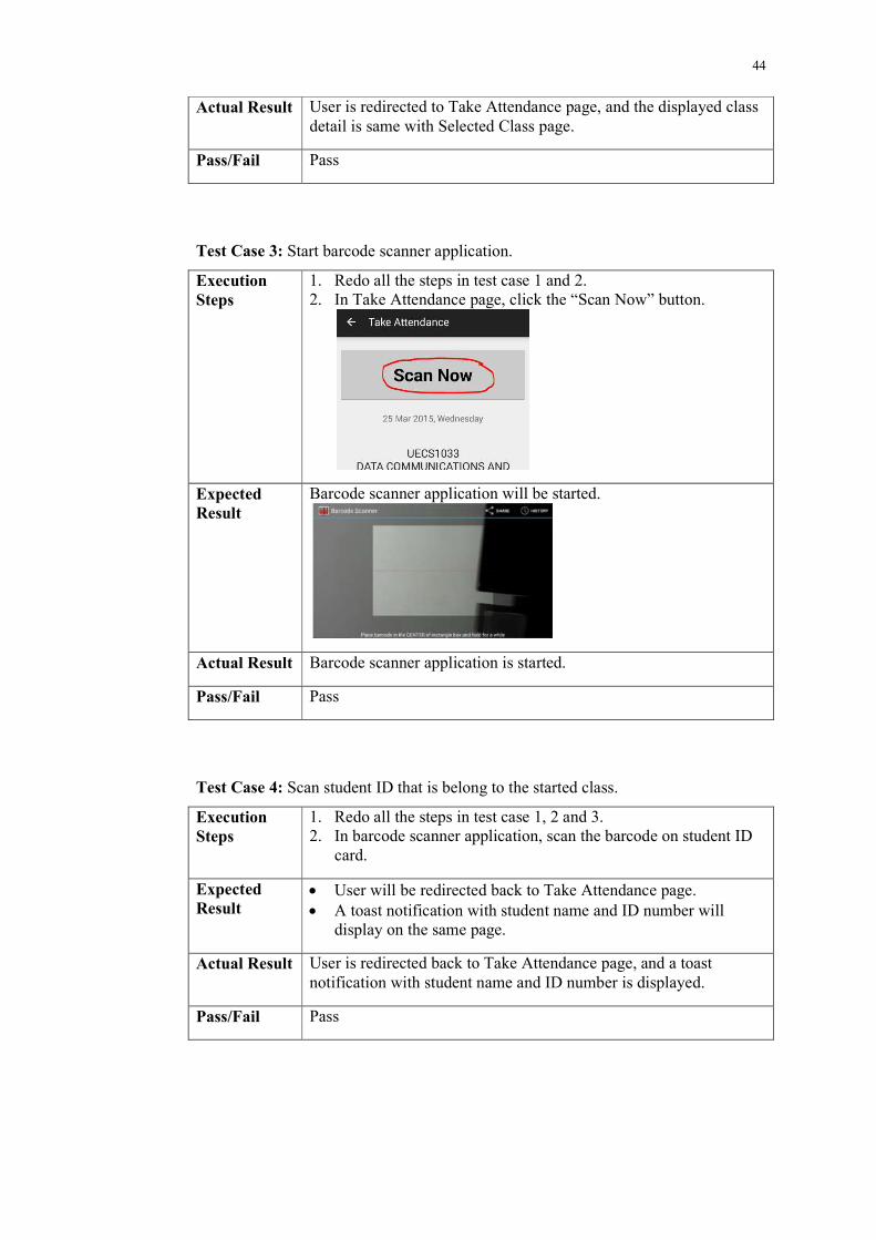
Test Case 3: Start barcode scanner application.
Execution Steps
1. Redo all the steps in test case 1 and 2. 2. In Take Attendance page, click the “Scan Now” button.
Expected Result
Barcode scanner application will be started.
Actual Result Barcode scanner application is started.
Pass/Fail Pass
Test Case 4: Scan student ID that is belong to the started class.
Execution Steps
1. Redo all the steps in test case 1, 2 and 3. 2. In barcode scanner application, scan the barcode on student ID
card.
Expected Result
User will be redirected back to Take Attendance page. A toast notification with student name and ID number will
display on the same page.
Actual Result User is redirected back to Take Attendance page, and a toast notification with student name and ID number is displayed.
Pass/Fail Pass
45
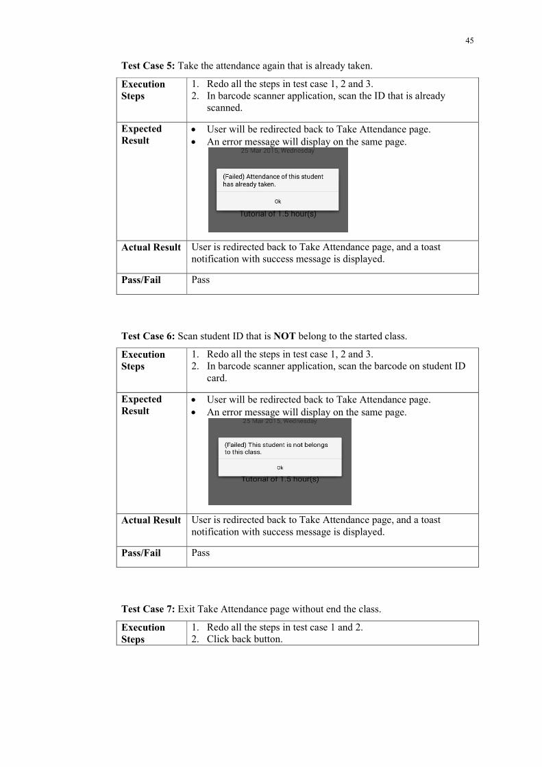
Test Case 5: Take the attendance again that is already taken.
Execution Steps
1. Redo all the steps in test case 1, 2 and 3. 2. In barcode scanner application, scan the ID that is already
scanned.
Expected Result
User will be redirected back to Take Attendance page. An error message will display on the same page.
Actual Result User is redirected back to Take Attendance page, and a toast notification with success message is displayed.
Pass/Fail Pass
Test Case 6: Scan student ID that is NOT belong to the started class.
Execution Steps
1. Redo all the steps in test case 1, 2 and 3. 2. In barcode scanner application, scan the barcode on student ID
card.
Expected Result
User will be redirected back to Take Attendance page. An error message will display on the same page.
Actual Result User is redirected back to Take Attendance page, and a toast notification with success message is displayed.
Pass/Fail Pass
Test Case 7: Exit Take Attendance page without end the class.
Execution Steps
1. Redo all the steps in test case 1 and 2. 2. Click back button.
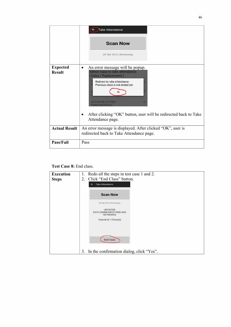
46
Expected Result
An error message will be popup.
After clicking “OK” button, user will be redirected back to Take Attendance page.
Actual Result An error message is displayed. After clicked “OK”, user is redirected back to Take Attendance page.
Pass/Fail Pass
Test Case 8: End class.
Execution Steps
1. Redo all the steps in test case 1 and 2. 2. Click “End Class” button.
3. In the confirmation dialog, click “Yes”.
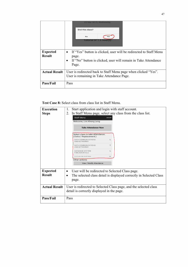
47
Expected Result
If “Yes” button is clicked, user will be redirected to Staff Menu page.
If “No” button is clicked, user will remain in Take Attendance Page.
Actual Result User is redirected back to Staff Menu page when clicked “Yes”. User is remaining in Take Attendance Page.
Pass/Fail Pass
Test Case 8: Select class from class list in Staff Menu.
Execution Steps
1. Start application and login with staff account. 2. In Staff Menu page, select any class from the class list.
Expected Result
User will be redirected to Selected Class page. The selected class detail is displayed correctly in Selected Class
page.
Actual Result User is redirected to Selected Class page, and the selected class detail is correctly displayed in the page.
Pass/Fail Pass
48
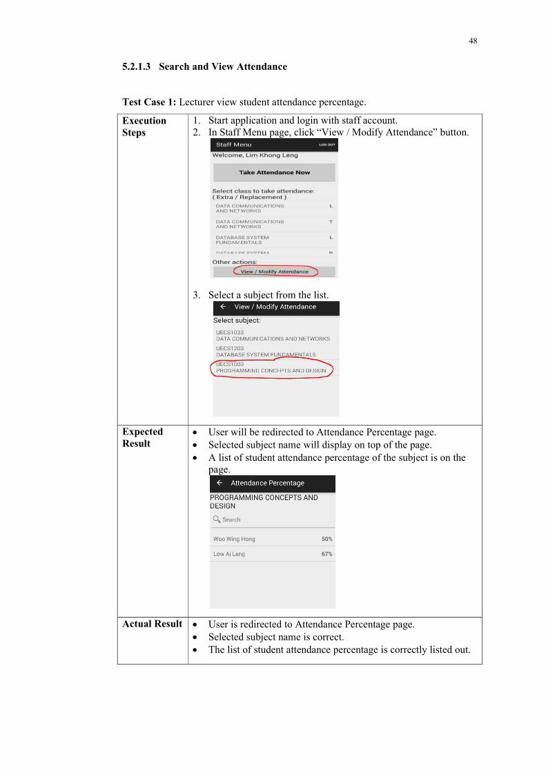
5.2.1.3 Search and View Attendance
Test Case 1: Lecturer view student attendance percentage.
Execution Steps
1. Start application and login with staff account. 2. In Staff Menu page, click “View / Modify Attendance” button.
3. Select a subject from the list.
Expected Result
User will be redirected to Attendance Percentage page. Selected subject name will display on top of the page. A list of student attendance percentage of the subject is on the
page.
Actual Result User is redirected to Attendance Percentage page. Selected subject name is correct. The list of student attendance percentage is correctly listed out.
49
Pass/Fail Pass
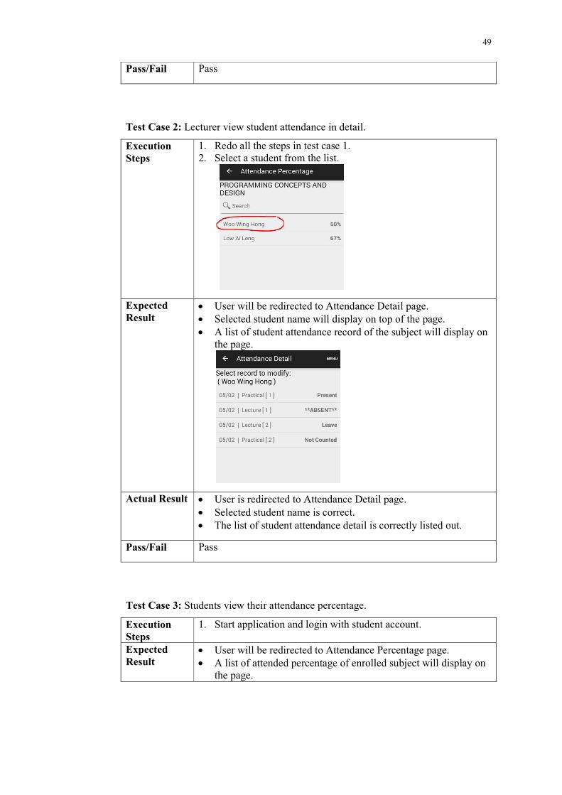
Test Case 2: Lecturer view student attendance in detail.
Execution Steps
1. Redo all the steps in test case 1. 2. Select a student from the list.
Expected Result
User will be redirected to Attendance Detail page. Selected student name will display on top of the page. A list of student attendance record of the subject will display on
the page.
Actual Result User is redirected to Attendance Detail page. Selected student name is correct. The list of student attendance detail is correctly listed out.
Pass/Fail Pass
Test Case 3: Students view their attendance percentage.
Execution Steps
1. Start application and login with student account.
Expected Result
User will be redirected to Attendance Percentage page. A list of attended percentage of enrolled subject will display on
the page.
50
Actual Result User is redirected to Attendance Percentage page. A list of attended percentage of enrolled subject is correctly
display on the page.
Pass/Fail Pass
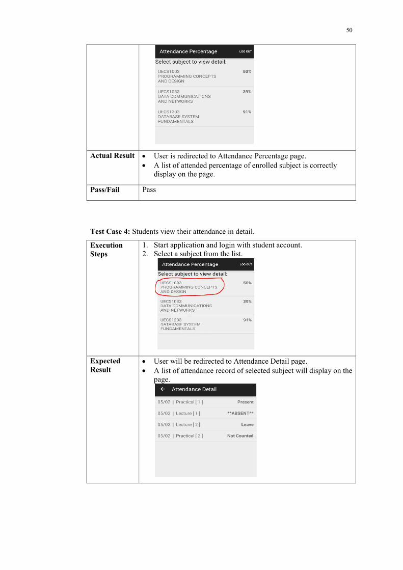
Test Case 4: Students view their attendance in detail.
Execution Steps
1. Start application and login with student account. 2. Select a subject from the list.
Expected Result
User will be redirected to Attendance Detail page. A list of attendance record of selected subject will display on the
page.
51
Actual Result User is redirected to Attendance Detail page. A list of attendance record of selected subject is displayed
correctly on the page.
Pass/Fail Pass
5.2.1.4 Modify Attendance
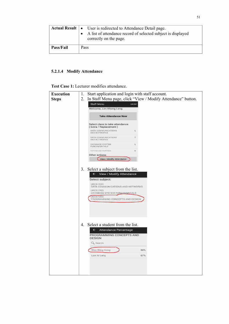
Test Case 1: Lecturer modifies attendance.
Execution Steps
1. Start application and login with staff account. 2. In Staff Menu page, click “View / Modify Attendance” button.
3. Select a subject from the list.
4. Select a student from the list.
52
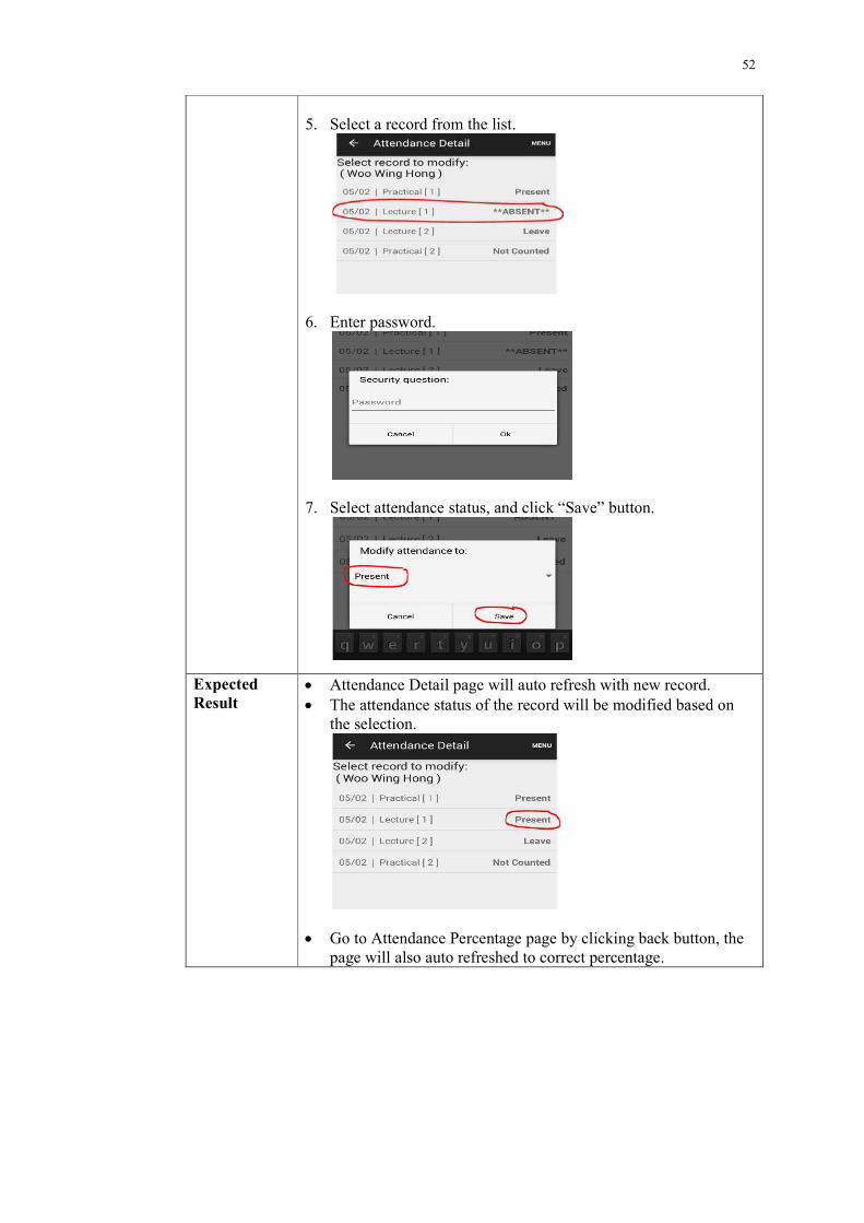
5. Select a record from the list.
6. Enter password.
7. Select attendance status, and click “Save” button.
Expected Result
Attendance Detail page will auto refresh with new record. The attendance status of the record will be modified based on
the selection.
Go to Attendance Percentage page by clicking back button, the page will also auto refreshed to correct percentage.
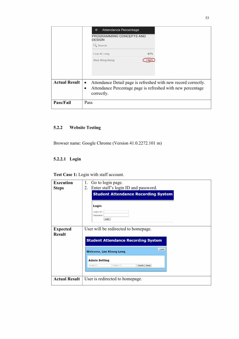
53
Actual Result Attendance Detail page is refreshed with new record correctly. Attendance Percentage page is refreshed with new percentage
correctly.
Pass/Fail Pass
5.2.2 Website Testing
Browser name: Google Chrome (Version 41.0.2272.101 m)
5.2.2.1 Login
Test Case 1: Login with staff account.
Execution Steps
1. Go to login page. 2. Enter staff’s login ID and password.
Expected Result
User will be redirected to homepage.
Actual Result User is redirected to homepage.
54
Pass/Fail Pass
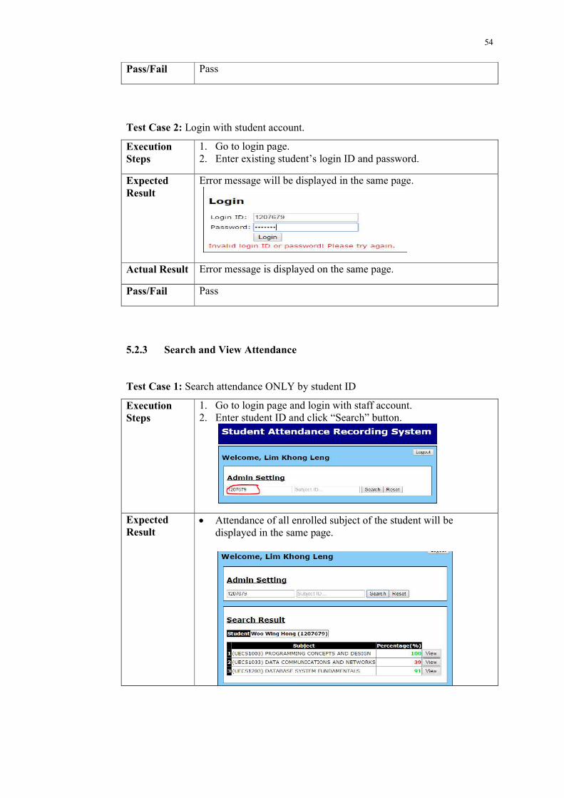
Test Case 2: Login with student account.
Execution Steps
1. Go to login page. 2. Enter existing student’s login ID and password.
Expected Result
Error message will be displayed in the same page.
Actual Result Error message is displayed on the same page.
Pass/Fail Pass
5.2.3 Search and View Attendance
Test Case 1: Search attendance ONLY by student ID
Execution Steps
1. Go to login page and login with staff account. 2. Enter student ID and click “Search” button.
Expected Result
Attendance of all enrolled subject of the student will be displayed in the same page.
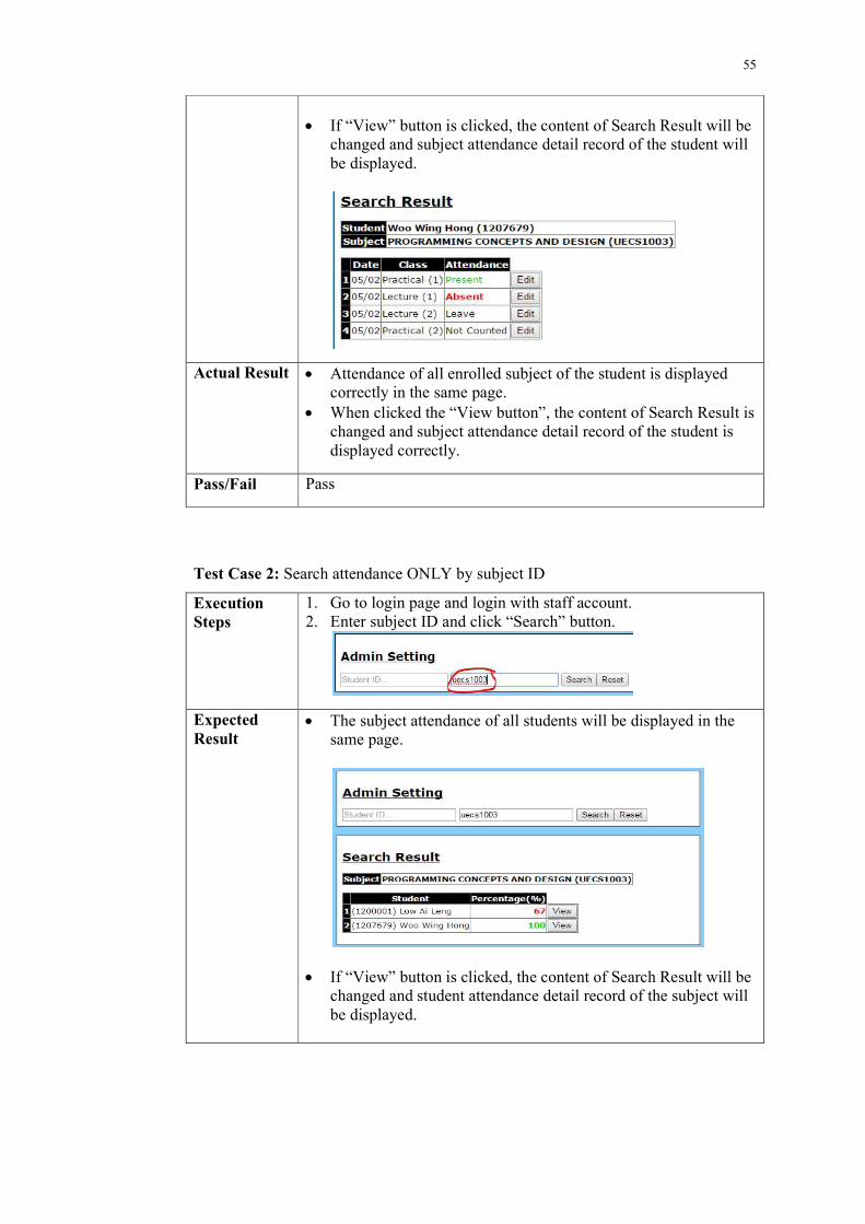
55
If “View” button is clicked, the content of Search Result will be
changed and subject attendance detail record of the student will be displayed.
Actual Result Attendance of all enrolled subject of the student is displayed correctly in the same page.
When clicked the “View button”, the content of Search Result is changed and subject attendance detail record of the student is displayed correctly.
Pass/Fail Pass
Test Case 2: Search attendance ONLY by subject ID
Execution Steps
1. Go to login page and login with staff account. 2. Enter subject ID and click “Search” button.
Expected Result
The subject attendance of all students will be displayed in the same page.
If “View” button is clicked, the content of Search Result will be
changed and student attendance detail record of the subject will be displayed.
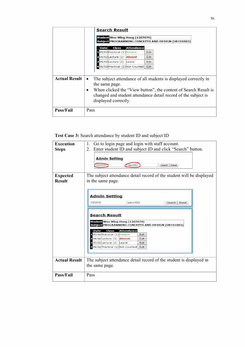
56
Actual Result The subject attendance of all students is displayed correctly in the same page.
When clicked the “View button”, the content of Search Result is changed and student attendance detail record of the subject is displayed correctly.
Pass/Fail Pass
Test Case 3: Search attendance by student ID and subject ID
Execution Steps
1. Go to login page and login with staff account. 2. Enter student ID and subject ID and click “Search” button.
Expected Result
The subject attendance detail record of the student will be displayed in the same page.
Actual Result The subject attendance detail record of the student is displayed in the same page.
Pass/Fail Pass
57
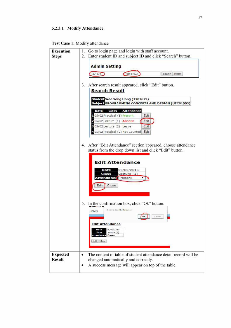
5.2.3.1 Modify Attendance
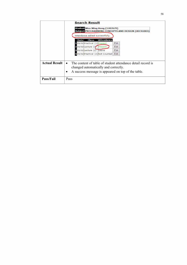
Test Case 1: Modify attendance
Execution Steps
1. Go to login page and login with staff account. 2. Enter student ID and subject ID and click “Search” button.
3. After search result appeared, click “Edit” button.
4. After “Edit Attendance” section appeared, choose attendance status from the drop down list and click “Edit” button.
5. In the confirmation box, click “Ok” button.
Expected Result
The content of table of student attendance detail record will be changed automatically and correctly.
A success message will appear on top of the table.
58
Actual Result The content of table of student attendance detail record is changed automatically and correctly.
A success message is appeared on top of the table.
Pass/Fail Pass
59
CHAPTER 6
6 CONCLUSION AND RECOMMENDATION
6.1 Limitation and Future Improvement
The limitation of the system developed is the speed of getting student ID from
barcode scanner application is slow. This is because the barcode scanner application
needs to complete few processes which are included capturing image, image
processing and analysis for the captured image. In order to finish these three
processes may takes some time.
In addition, there are some future improvements suggested for the developed
system:
System developed can integrate with system of university.
System developed should eliminate the hardcoded data in the database.
The mobile application can add feature that allow lecturer to take attendance
without Internet connection.
The mobile application can add more methods to get student ID number.
Suggested method:
o New feature of mobile application that allow student to send their ID
number to lecturer’s mobile device by using connectivity technoblogy
such as Near-Field-Communication (NFC), Bluetooth and Wi-Fi P2P.
Fully integrate the barcode scanner application to the mobile application so
user can use barcode scanner feature without installing the scanner
application.
60
6.2 Conclusion
This project aims to provide a new method to take student attendance for all the
universities. Lecturers can take student attendance, view student attendance and
modify student attendance with mobile device. It is a “smarter” way to complete the
task.
This project is completed by referring and following the project plan planned
during the planning phases. The project breakdown in the project plan also acts as a
guidance of this project.
In the conclusion, the result of this project has met all the requirements
gathered during the planning and analysis phases. The system developed with the
selected methodology. It is also passed all the test cases.
This project can be guidance and reference for future people who are going to
develop the system similar to this project. People can refer this project and come up
with a more creative and innovative idea.
61
6 REFERENCES
Android (no date) Android Developer Tools [Online] Available at
http://developer.android.com/tools/index.html. Accessed on 18th July 2014.
IDAutomation (2012) Barcode Educational Guide. IDAutomation.com, Inc. [Online].
Available at http://www.idautomation.com/barcode-faq/barcode-educational-
guide.pdf. Accessed on 2nd August 2014.
Janaswamy Phaniteja, P Derin J Tom (no date) Evolution of Barcode. International
Journal for Development of Computer Science & Technology. [Online] Available at
http://www.ijdcst.com/pdf/Evolution%20of%20Barcode.pdf. Accessed on 2nd
August 2014.
Bibase Software (no date) The ASCII Table. [Image] Available at
http://www.bibase.com/ascii.htm. Accessed on 3th August 2014.
FingerTec (2007) Overview of Punch Card & Card Reader System [Online]
Available at http://www.fingertec.com/newsletter/images/PunchCard-E.pdf.
Accessed on 8th August 2014.
Dr.M.Ramakrishnan, Josphineleela.R (2012) An Efficient Automatic Attendance
System Using Fingerprint Reconstruction Technique. International Journal of
Computer Science and Information Security. [Online] Available at
http://arxiv.org/ftp/arxiv/papers/1208/1208.1672.pdf. Accessed on 8th August 2014.
Abhishek Jha (no date) Class Room Attendance System Using Facial Recognition
System. The International Journal of Mathematics, Science, Technology and
Management. [Online] Available at http://klresearch.org/IJMSTM/papers/v2i3_2.pdf.
Accessed on 8th August 2014.
Eisaku Ohbuchi, Hiroshi Hanaizumi, Lim Ah Hock (2004) Barcode Reader using the
Camera Device in Mobile Phone. IEEE Computer Society.

62