
Struds Tutorials
238
STRUDS TUTORIALS STRUDS STRUDS TUTORIALS TUTORIALS 1
-
Upload
kg-rohilla -
Category
Documents
-
view
191 -
download
7
Transcript of Struds Tutorials
STRUDS TUTORIALS
STRUDS STRUDS TUTORIALSTUTORIALS
1

STRUDS TUTORIALS
The information in this tutorial Guide is subject to change without notice because of the continuos process of software enhancement / improvement. SOFTTECH is in no way responsible for any errors that may appear in this Tutorial Guide or due to its usage.
Copyright © 1998, SoftTech Engineers Pvt. Ltd.
Requests and Orders to :
SoftTech Engineers Pvt. Ltd.1 - Balaji House, Opp. Telephone Exchange,Bajirao Road, Pune 411 030.India.Telephone - +91-020-4478084Telefax - +91-020-4478085Web : http://www.softtech-engr.comEmail : [email protected]
2
STRUDS TUTORIALS
INDEX
1. PREFACE2. GETTING STARTED3. ANALYSIS{I.} ANALYSIS OF SIMPLY SUPPORTED BEAM {I-1} PREPROCESSOR {I-1.1} Creating Beam Element {I-1.2} Creating and Attaching Section To Beam Element {I-1.3} Creating and Attaching Loads To Beam Element {I-1.4} Attaching Material To The Beam Element {I-1.5} Defining Support Conditions {I-1.6} PreAnanlysis Enquiry. {I-1.7} Saving The Building File. {I-2} ANALYSIS {I-2.1} Analysing The Beam. {I-3} POSTPROCESSOR {I-3.1} Selecting The Structure Type. {I-3.2} Vector Diagram Display. {I-3.3} Creating New Load Combination. {I-3.4} Displaying Shear Force Diagram. {I-3.5} Using The Control Option {I-3.6} Displaying Bending Moment Diagram. {I-3.7} Displaying Deflection Diagram. {I-3.8} Free Body Diagram of the beam element. {I-3.9} Displaying Reactions {II} - ANALYSIS OF A FIXED BEAM {II-1} PREPROCESSOR {III} ANALYSIS OF CONTINUOUS BEAM WITH OVERHANG {III-1} PREPROCESSOR {III-1.1} Creating Beam Element {III-1.2} Defining Support Conditions {III-1.3} Creating and Attaching Loads To The Beam Element {IV} ANALYSIS OF SIMPLE PORTAL FRAME {IV-1} PREPROCESSOR {IV-1.1} Creation Of The Portal Frame {IV-1.2} Defining The Support Conditions {IV-1.3} Creating and Attaching The Section {IV-1.4} Creating And Attaching The Loads {V} ANALYSIS OF RIGID FRAME {V-1} PREPROCESSOR {V-1.1} Creating Beam Element {V-1.2} Defining Support Condition {V-1.3} Creating and Attaching Section To the Elements. {V-1.4} Creating and Attaching Loads To The Beam Element
3
STRUDS TUTORIALS
4. INDIVIDUAL DESIGN MODULE
{VI} DESIGN OF ONE – WAY SLAB {VI-1.1} Creating Slab {VI-1.2} Designing The Slab {VI-1.3} Displaying Design Results {VII} DESIGN OF BEAM {VII-1.1} Inputing Beam Geometry {VII-1.2} Defining The Beam Supports {VII-1.3} Creating And Attaching Load {VII-1.4} Creating And Attaching Beam Section {VII-1.5} Attaching Material To The Beam {VII-1.6} Analysing The Beam {VII-1.7} Designing The Beam {VII-1.8} Display of Results {VII-1.9} Display of Design Results {VIII} COLUMN DESIGN {VIII-1.1} Creating Column Geometry {VIII-1.2} Creating A New Load Combination {VIII-1.3} Designing of Column {VIII-1.4} Display of Design {IX} FOOTING DESIGN {IX-1.1} Selecting The Type Of Footing {IX-1.2} Inputting Column Details {IX-1.3} Designing of Footing
5. BUILDING DESIGN
{X} SAMPLE BUILDING DESIGN
{X-1} PREPROCESSOR {X-1.1a} Defining Floors {X-1.1b} Creating Slabs Panels {X-1.1c} Drawing Curved Element {X-1.2} Locating Column Positions {X-1.3} Specifying Boundary Conditions {X-1.4} Creating And Attaching Sections to Beams {X-1.5} Creating and Attaching Walls {X-1.6} Creating and Attaching External Loads {X-1.7} Saving Floor Plan {X-1.8} Copying the Floor Plans {X-1.9} Editing The Floor Plans {X-1.10} Setting Column sizes and Orientation of Columns{X-2} ANALYZING THE BUILDING STRUCTURE {X-3} PLANE GRID METHOD{X-3A} ANALYSIS {X-3} DESIGN
4
STRUDS TUTORIALS
{X-3.1} SLAB DESIGN {X-3.1.1} Defining Properties {X-3.1.2} Displaying Slab Design Results{X-3.2} BEAM DESIGN {X-3.2.1} Defining Beam Properties {X-3.2.2} Displaying Beam Schedule {X-3.2.3} Display of The Bar Bending Schedule {X-3.2.4} Display of Beam Quantity Report. {X-3.2.5} Display The Double Line Diagram {X-3.2.6} Displaying The Analysis Results. {X-3.2.7} Display of Design Results.{X-3.3} COLUMN DESIGN {X-3.3.1} Defining Properties {X-3.3.2} Displaying Column Design {X-3.3.3} Displaying Cumulative Loads {X-3.3.4} Displaying The Centerline Plan {X-3.3.5} Displaying Column Design Results {X-3.3.6} Displaying The Quantity Summary {X-3.3.7} Displaying The Column Load Report{X-3.4} FOOTING DESIGN {X-3.4.1} Defining Design Parameters {X-3.4.2} Displaying Footing Design Results {X-3.4.3} Displaying Footing Plan + Elevation {X-3.4.4} Displaying Footing Schedule {X-3.4.5} Displaying Footing Quantity Report {X-3.4.6} Displaying Cenerline-Plan For Footings
{X-A} PLANE FRAME METHOD
{X-A 1} PREPROCESSOR {X-A 1.1} Generating Plane Frames {X-A 1.2} Generating Seismic and Wind Loads {X-A 1.3} Viewing EQ and Wind Load Report {X-A 1.4} Viewing of Frames and Horizontal Loads {X-A 2} ANALYSIS {X-A 3} DESIGN BEAM DESIGN {X-A 3.1} Creating New Load Combinations {X-A 3.2} Beam Design {X-A 3.3} Displaying Beam Schedule {X-A 3.4} Displaying Bar Bending Schedule. {X-A 3.5} Displaying Beam Quantity Report. {X-A 3.6} Displaying Analysis Results. {X-A 3.7} Displaying Beam Design Results. COLUMN DESIGN {X-A 3.8} Column Design {X-A 3.9} Column Numbering {X-A 3.10} Defining Column Design Parameters {X-A 3.11} Saving Column Design
5
STRUDS TUTORIALS
{X-A 3.12} Displaying Column Design {X-A 3.13} Displaying Loads On Column {X-A 3.14} Displaying Centerline Plan {X-A 3.15} Displaying Column Cross Section {X-A 3.16} Displaying Column Schedule {X-A 3.17} Displaying Column Quantity Report {X-A 3.18} Displaying Column Load Report. {X-A 3.19} Displaying Detail Column Design Report. {X-A 3.20} Displaying Column Schedule Report. FOOTING DESIGN {X-A 3.21} Footing Design {X-A 3.22} Defining Design Parameters {X-A 3.23} Displaying Design {X-A 3.24} Displaying Plan + Elevation. {X-A 3.25} Displaying Footing Schedule {X-A 3.26} Displaying Quantity Report {X-A 3.27} Displaying Footing Center-Line Plan
{X-B} SPACE FRAME METHOD
{X-B1} PREPROCESSOR {X-B 1.1} Generating Space Frame {X-B 1.2} Displaying Space Frame {X-B 1.3} Generating Seismic and Wind Loads {X-B 1.4} Defining Load Cases {X-B 2} ANALYSIS {X-B 3} DESIGN BEAM DESIGN {X-B 3.1} Creating New Load Combinations For Beam Design {X-B 3.2} Beam Design By Space Frame Method {X-B 3.3} Saving Design {X-B 3.4} Grouping Of Beams {X-B 3.5} Displaying Beam Schedule {X-B 3.6} Display of Reports {X-B 3.7} Displaying Analysis Results {X-B 3.8} Displaying Design Results. COLUMN DESIGN {X-B 3.9} Column Design {X-B 3.10} Column Numbering {X-B 3.11} Defining Design Properties {X-B 3.12} Saving Column Design {X-B 3.13} Displaying Design {X-B 3.14} Displaying Loads {X-B 3.15} Displaying Center Line Plan {X-B 3.16} Displaying Column Schedule Report {X-B 3.17} Displaying Column Quantity Report. {X-B 3.18} Displaying Column Load Report {X-B 3.19} Displaying Detail Report Of Column Design. FOOTING DESIGN
6
STRUDS TUTORIALS
{X-B 3.20} Footing Design {X-B 3.21} Displaying Footing Design {X-B 3.22} Displaying Footing Design {X-B 3.23} Displaying Plan + Elevation {X-B 3.24} Displaying Footing Schedule {X-B 3.25} Displaying Footing Quantity Report. {X-B 3.26} Displaying Footing Centerline Plan.
7
STRUDS TUTORIALS
PREFACEWith the positive response of the users to the STRUDS TUTORIAL GUIDE published earlier we have decided to update the tutorial guide. This STRUDS TUTORIALS includes the new features of STRUDS version 6.5.
The purpose of this Tutorials is to explain in brief the main features of STRUDS by working on analysis of beams, portal frames, rigid frames and design of individual slab, beam, column, footings. The part of analysis of beams, portal frames, rigid frames is included newly so that the young engineers can get familiar with the use of the elementary commands. The Individual Design part is to explain the new features added in the STRUDS. Also a sample Building design is explained as a Project. Though all the commands of STRUDS are not covered in this, most of the commands required for model generation, analysis and design are made use of.
In order to get conversant with the STRUDS, the user can go on exploring the various commands the details of which are already explained in the STRUDS MANNUAL.
8
STRUDS TUTORIALS
Getting StartedOnce you have installed STRUDS on your computer, you can now run STRUDS by using following menu options.
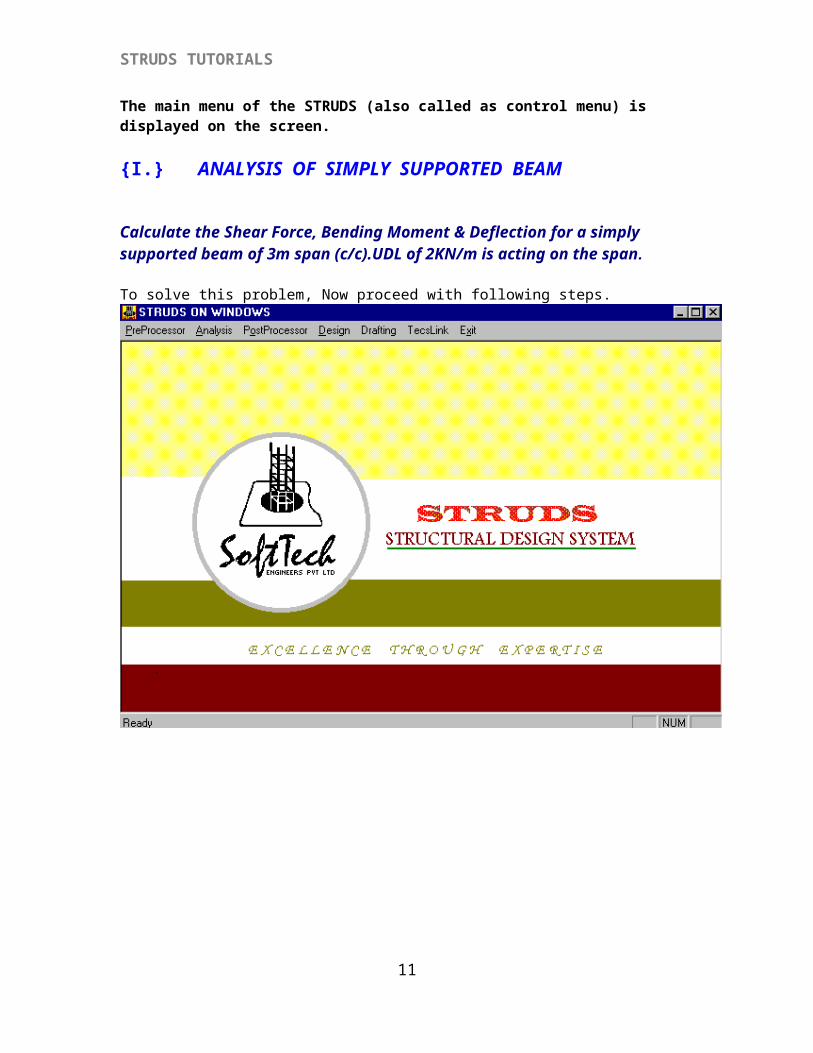
Click the ‘START’ button of windows95 menu bar.Click ‘Program’ option from the pull – up menu.Click ‘STRUDS ON WINDOWS’ option from the menu.The main menu of the STRUDS (also called as control menu) is displayed on the screen.
{I.} ANALYSIS OF SIMPLY SUPPORTED BEAM
Calculate the Shear Force, Bending Moment & Deflection for a simply supported beam of 3m span (c/c).UDL of 2KN/m is acting on the span.
To solve this problem, Now proceed with following steps.
9
STRUDS TUTORIALS
10
STRUDS TUTORIALS
{I-1} PREPROCESSORThis module is the first module that you will be operating while using STRUDS. It accepts all the input data provided by you in graphical form and proceeds to create a 2D or 3D model of the structure. This is the core module of STRUDS program and is co-related with all other modules for their working. It should be noted that unless you pre-process a structure geometry, the analysis, post-processing or design of the same could not be done. The Pre Processor creates a file having any name up to 8 characters as provided by you having extension.BLD in which all the data of the building project is stored.
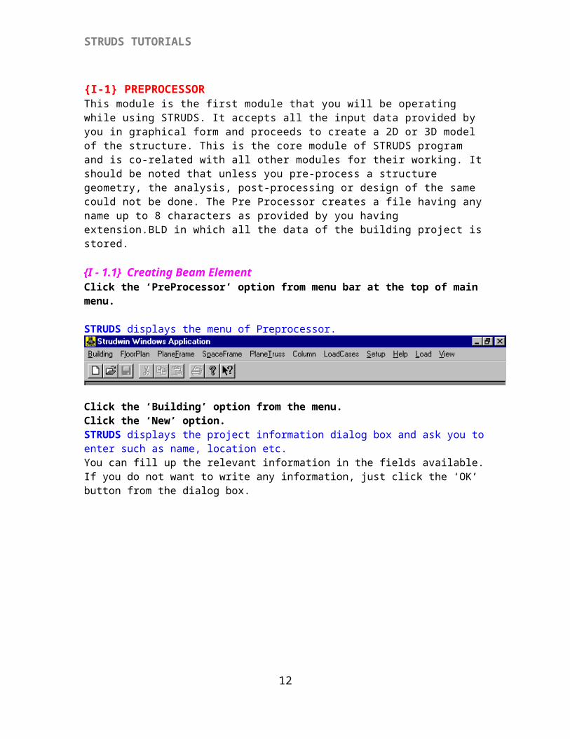
{I - 1.1} Creating Beam ElementClick the ‘PreProcessor’ option from menu bar at the top of main menu.
STRUDS displays the menu of Preprocessor.
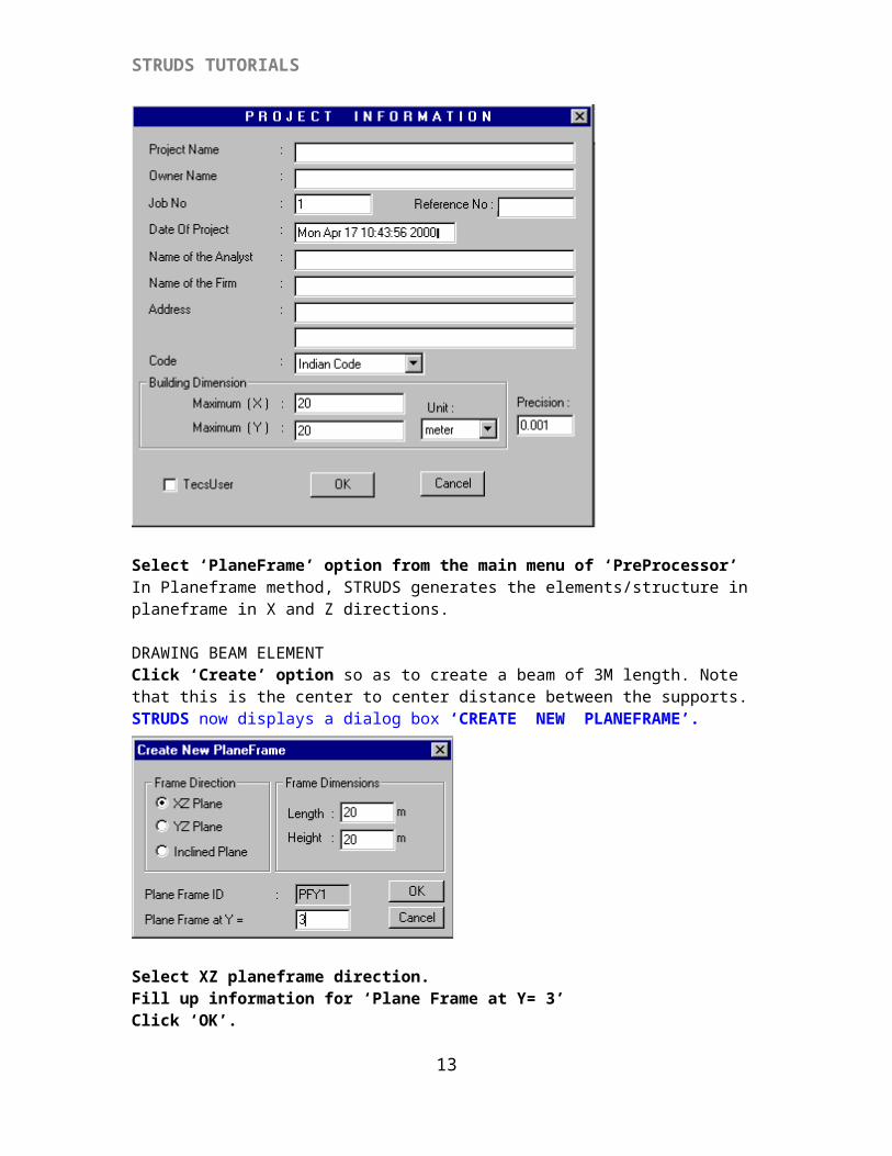
Click the ‘Building’ option from the menu.Click the ‘New’ option.STRUDS displays the project information dialog box and ask you to enter such as name, location etc.You can fill up the relevant information in the fields available. If you do not want to write any information, just click the ‘OK’ button from the dialog box.
11
STRUDS TUTORIALS
Select ‘PlaneFrame’ option from the main menu of ‘PreProcessor’In Planeframe method, STRUDS generates the elements/structure in planeframe in X and Z directions.
DRAWING BEAM ELEMENTClick ‘Create’ option so as to create a beam of 3M length. Note that this is the center to center distance between the supports.STRUDS now displays a dialog box ‘CREATE NEW PLANEFRAME’.
Select XZ planeframe direction.Fill up information for ‘Plane Frame at Y= 3’ Click ‘OK’.STRUDS displays the following window.
12
STRUDS TUTORIALS
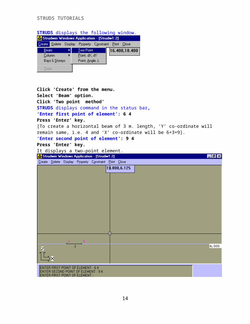
Click ‘Create’ from the menu.Select ‘Beam’ option.Click 'Two point method’ STRUDS displays command in the status bar,‘Enter first point of element’: 6 4Press ‘Enter’ key.[To create a horizontal beam of 3 m. length, ‘Y’ co-ordinate will remain same, i.e. 4 and ‘X’ co-ordinate will be 6+3=9].‘Enter second point of element’: 9 4Press ‘Enter’ key.It displays a two-point element.
{I-1.2} Creating and Attaching Section To Beam ElementWhile solving such type of problems manually we don’t have to consider the beam section, but the software requirement is that you have to create and attach section and material to the beam element without considering the self-weight of the beam. For that,
13
STRUDS TUTORIALS
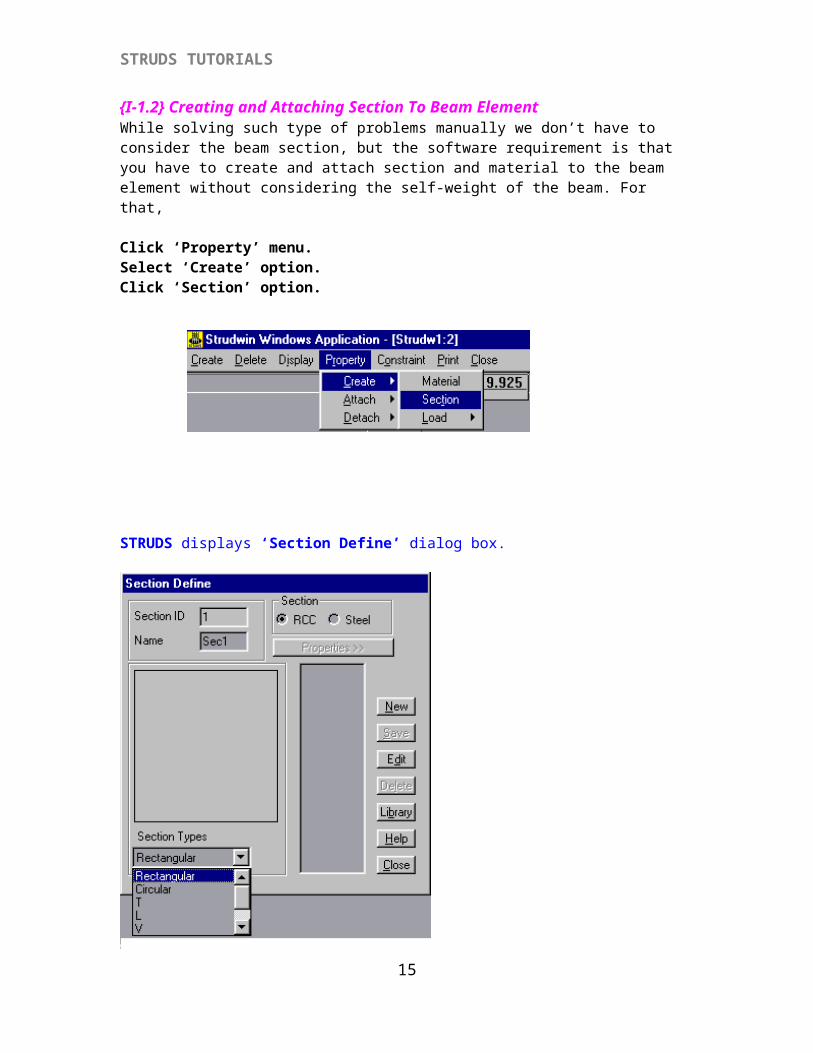
Click ‘Property’ menu.Select ‘Create’ option.Click ‘Section’ option.
STRUDS displays ‘Section Define’ dialog box.
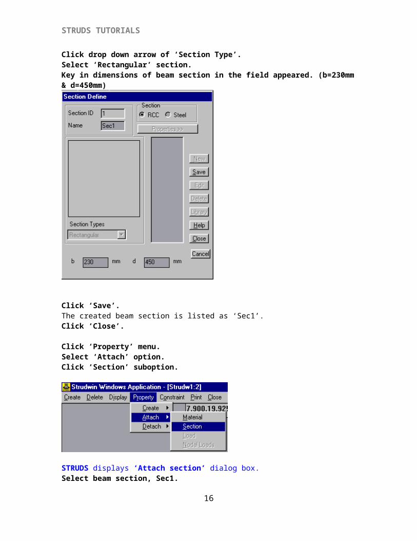
Click drop down arrow of ‘Section Type’.Select ‘Rectangular’ section.Key in dimensions of beam section in the field appeared. (b=230mm & d=450mm)
14
STRUDS TUTORIALS
Click ‘Save’.The created beam section is listed as ‘Sec1’.Click ‘Close’.
Click ‘Property’ menu.Select ‘Attach’ option.Click ‘Section’ suboption.
STRUDS displays ‘Attach section’ dialog box.Select beam section, Sec1.
15
STRUDS TUTORIALS
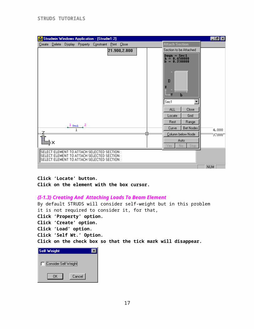
Click ‘Locate’ button.Click on the element with the box cursor.
{I-1.3} Creating And Attaching Loads To Beam ElementBy default STRUDS will consider self-weight but in this problem it is not required to consider it, for that,Click ‘Property’ option.Click ‘Create’ option.Click ‘Load’ option.Click ‘Self Wt.’ Option.Click on the check box so that the tick mark will disappear.
Click on ‘Property’ menu.Select ‘Create’ option.Select ‘Load’ option.
16
STRUDS TUTORIALS
Click ‘Elemental load’ option.STRUDS displays ‘Load Definition’ dialog box.
Click drop down arrow of load types.Select load type. [ Full UDL]- When you select this option, STRUDS asks you to provide W - intensity of Load Angle of Load at which it is acting on the element. When the angle is 90 degrees it indicates that the load is normal to the axis of element. Please note that while providing input downward load should be given as positive. The program however internally assigns -ve sign to all downward loads automatically.
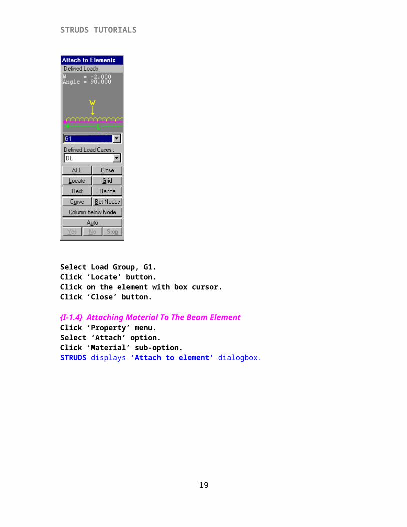
Key in load value 2 kN/m in the ‘W’ field appeared. Click ‘Save’ button.The selected load type is listed as G1.Click ‘Close’ button. Click ‘Property’ menu.Select ‘Attach’ option.Click ‘Load’ sub-option.STRUDS displays ‘Attach to Element’ dialog box.
17

STRUDS TUTORIALS
Select Load Group, G1.Click ‘Locate’ button.Click on the element with box cursor.Click ‘Close’ button.
{I-1.4} Attaching Material To The Beam ElementClick ‘Property’ menu.Select ‘Attach’ option.Click ‘Material’ sub-option.STRUDS displays ‘Attach to element’ dialogbox.
18
STRUDS TUTORIALS
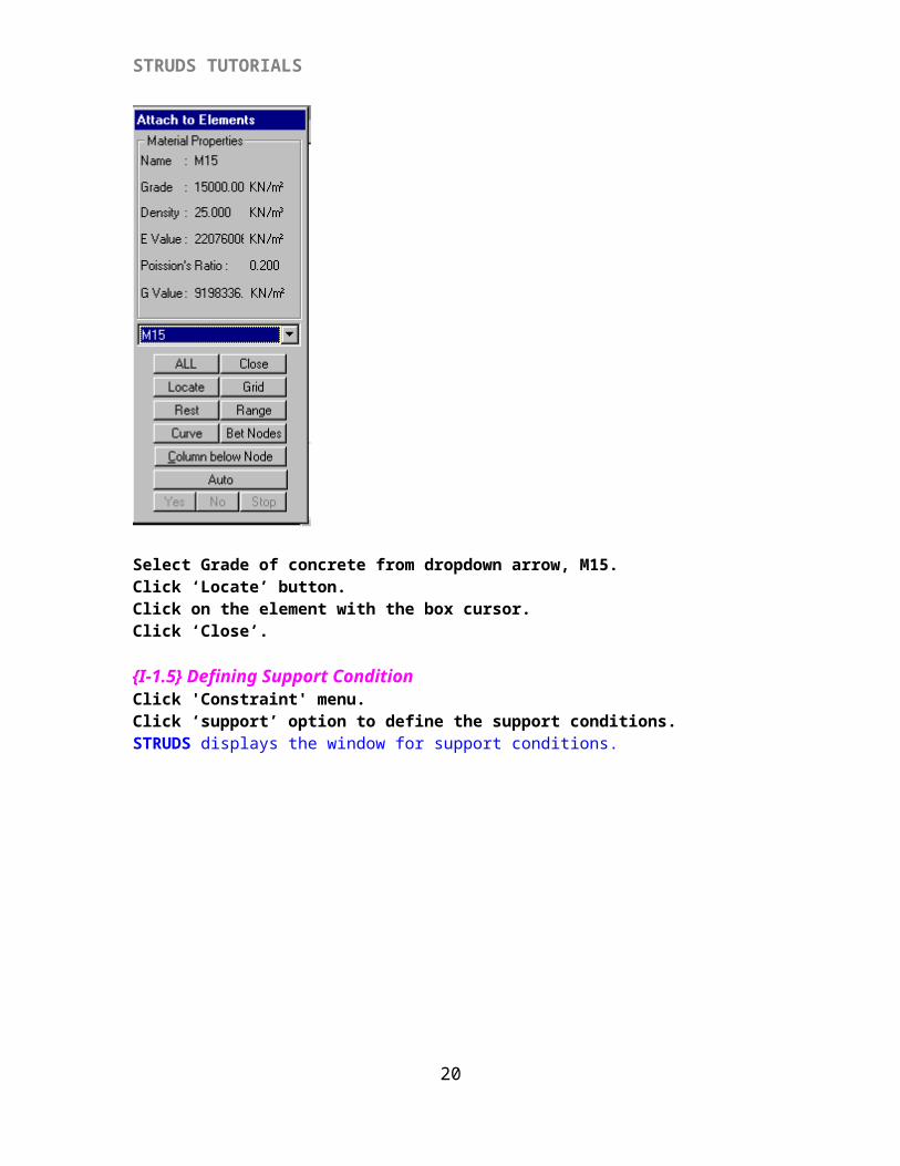
Select Grade of concrete from dropdown arrow, M15.Click ‘Locate’ button.Click on the element with the box cursor.Click ‘Close’.
{I-1.5} Defining Support ConditionClick 'Constraint' menu.Click ‘support’ option to define the support conditions.STRUDS displays the window for support conditions.
19
STRUDS TUTORIALS
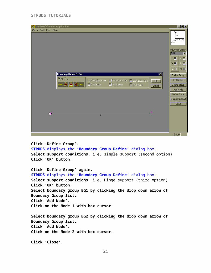
Click ‘Define Group’.STRUDS displays the ‘Boundary Group Define’ dialog box.Select support conditions, i.e. simple support (second option)Click ‘OK’ button.
Click ‘Define Group’ again.STRUDS displays the ‘Boundary Group Define’ dialog box.Select support conditions, i.e. Hinge support (third option)Click ‘OK’ button.Select boundary group BG1 by clicking the drop down arrow of Boundary Group list.Click ‘Add Node’.Click on the Node 1 with box cursor.
Select boundary group BG2 by clicking the drop down arrow of Boundary Group list.Click ‘Add Node’.Click on the Node 2 with box cursor.
Click ‘Close’.Click ‘Close’ option of the Window.
{I-1.6} PreAnanlysis Enquiry Click ‘Plane Frame’ menu option.Click the ‘Pre-Analysis Inquiry’ option.STRUDS displays ‘Pre-Analysis Information’ dialog box.
20
STRUDS TUTORIALS
This option allows you to verify the input for any discrepancy before saving the data files for analysis of plane frame. When you select this option STRUDS check the input data you have given and if any deficiency or discrepancy is found, it points out the same in a window message box.
Click ‘OK’.If any discrepancy occurs then rectify it and proceed further.
{I-1.7} Saving The Building FileClick ‘Building’ menu option.Click ‘Save’ option.Select the drive on which Strudwin is loaded.Select ‘Strudwin’ folder. Create a new folder as ‘data’.Key in the file name and click ‘Save’ button.
Click ‘Plane Frame’ menu option.Select ‘Analysis Files’ option.Click ‘All’.Click ‘Save’.
Click ‘Building’ menu option.Click ‘Exit’.
Here we have completed the ‘PRE PROCESSOR’ part of the ‘STRUDS '
{I-2} ANALYSIS
This menu allows you to perform the analysis of an element/structure.
{I-2.1} Analysing The BeamClick ‘Analysis’ from control menu of STRUDS. Open the building file.
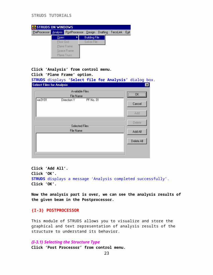
Click ‘Analysis’ from control menu.Click ‘Plane Frame’ option.STRUDS displays ‘Select file for Analysis’ dialog box.
21
STRUDS TUTORIALS
Click ‘Add All’.Click ‘OK’.STRUDS displays a message ‘Analysis completed successfully’.Click ‘OK’.
Now the analysis part is over, we can see the analysis results of the given beam in the Postprocessor.
{I-3} POSTPROCESSOR
This module of STRUDS allows you to visualize and store the graphical and text representation of analysis results of the structure to understand its behavior.
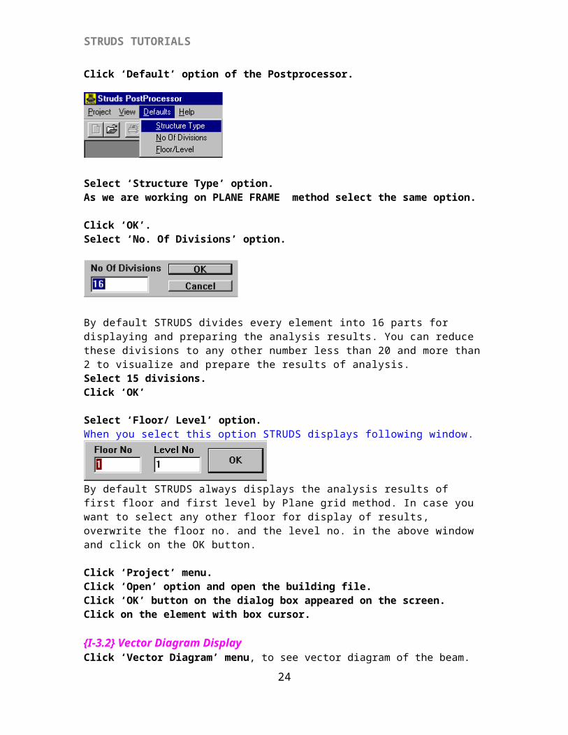
{I-3.1} Selecting the Structure TypeClick ‘Post Processor’ from control menu.Click ‘Default’ option of the Postprocessor.
Select ‘Structure Type’ option.As we are working on PLANE FRAME method select the same option.
Click ‘OK’.Select ‘No. Of Divisions’ option.
22
STRUDS TUTORIALS
By default STRUDS divides every element into 16 parts for displaying and preparing the analysis results. You can reduce these divisions to any other number less than 20 and more than 2 to visualize and prepare the results of analysis.Select 15 divisions.Click ‘OK’ Select ‘Floor/ Level’ option.When you select this option STRUDS displays following window.
By default STRUDS always displays the analysis results of first floor and first level by Plane grid method. In case you want to select any other floor for display of results, overwrite the floor no. and the level no. in the above window and click on the OK button.
Click ‘Project’ menu.Click ‘Open’ option and open the building file.Click ‘OK’ button on the dialog box appeared on the screen.Click on the element with box cursor.
{I-3.2} Vector Diagram DisplayClick ‘Vector Diagram’ menu, to see vector diagram of the beam.STRUDS displays vector diagram of the beam.
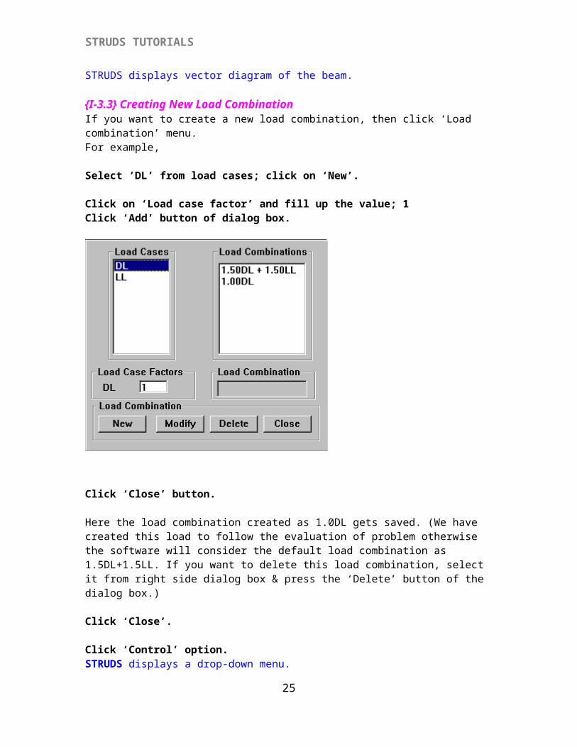
{I-3.3} Creating New Load CombinationIf you want to create a new load combination, then click ‘Load combination’ menu.For example,
Select ‘DL’ from load cases; click on ‘New’.
Click on ‘Load case factor’ and fill up the value; 1Click ‘Add’ button of dialog box.
23
STRUDS TUTORIALS
Click ‘Close’ button.
Here the load combination created as 1.0DL gets saved. (We have created this load to follow the evaluation of problem otherwise the software will consider the default load combination as 1.5DL+1.5LL. If you want to delete this load combination, select it from right side dialog box & press the ‘Delete’ button of the dialog box.)
Click ‘Close’.
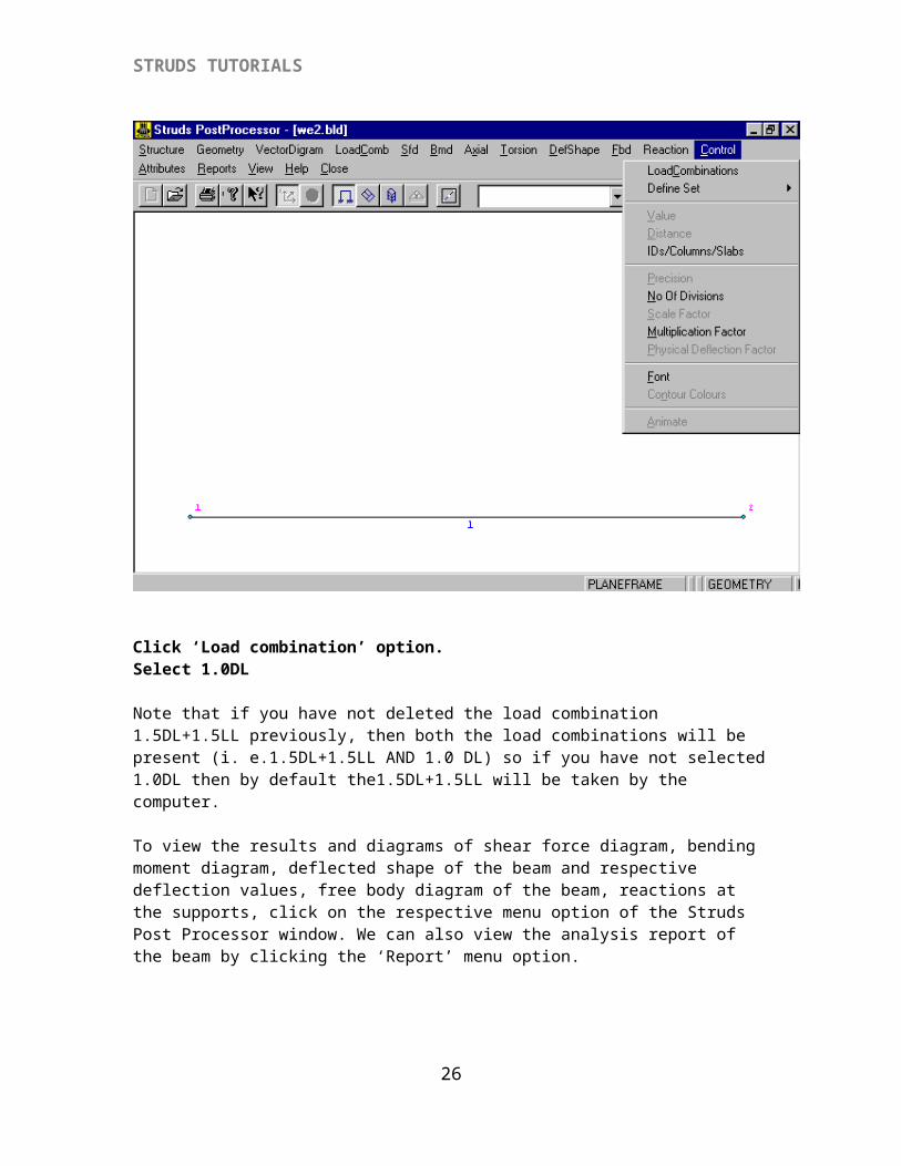
Click ‘Control’ option.STRUDS displays a drop-down menu.
24
STRUDS TUTORIALS
Click ‘Load combination’ option.Select 1.0DL
Note that if you have not deleted the load combination 1.5DL+1.5LL previously, then both the load combinations will be present (i. e.1.5DL+1.5LL AND 1.0 DL) so if you have not selected 1.0DL then by default the1.5DL+1.5LL will be taken by the computer.
To view the results and diagrams of shear force diagram, bending moment diagram, deflected shape of the beam and respective deflection values, free body diagram of the beam, reactions at the supports, click on the respective menu option of the Struds Post Processor window. We can also view the analysis report of the beam by clicking the ‘Report’ menu option.
25
STRUDS TUTORIALS
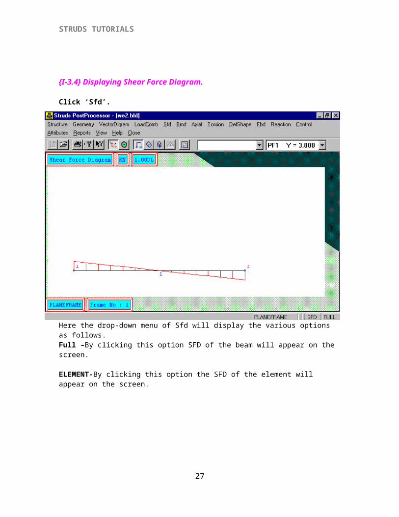
{I-3.4} Displaying Shear Force Diagram.
Click ‘Sfd’.Here the drop-down menu of Sfd will display the various options as follows.
Full –By clicking this option SFD of the beam will appear on the screen.
ELEMENT-By clicking this option the SFD of the element will appear on the screen.
26
STRUDS TUTORIALS
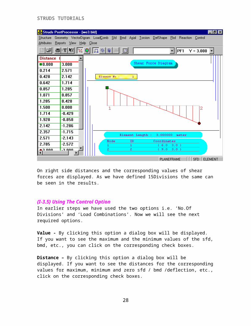
On right side distances and the corresponding values of shear forces are displayed. As we have defined 15Divisions the same can be seen in the results.
{I-3.5} Using The Control Option In earlier steps we have used the two options i.e. ‘No.Of Divisions’ and ‘Load Combinations’. Now we will see the next required options.
Value - By clicking this option a dialog box will be displayed. If you want to see the maximum and the minimum values of the sfd, bmd, etc., you can click on the corresponding check boxes.
Distance – By clicking this option a dialog box will be displayed. If you want to see the distances for the corresponding values for maximum, minimum and zero sfd / bmd /deflection, etc., click on the corresponding check boxes.
Precision – By clicking this option a dialog box will be displayed. Two types of precision are available, Value Precision and Distance precision. Default setting for both is 3. It means that the values will be displayed as three digits after the decimal point. You can change any type of precision if you want. Note that you can give the value upto 5 only.
Scale Factor – By clicking this option a dialog box will be displayed. Default setting is 1. You can change the value so as to view the various diagrams as per your desire.
27
STRUDS TUTORIALS
Multiplication Factor – By default its value is 1. For our example we don’t have to change this value.
Font – By clicking this option you can change the properties of display of various factors.i.e. You can change Font / font style / size / colour etc.
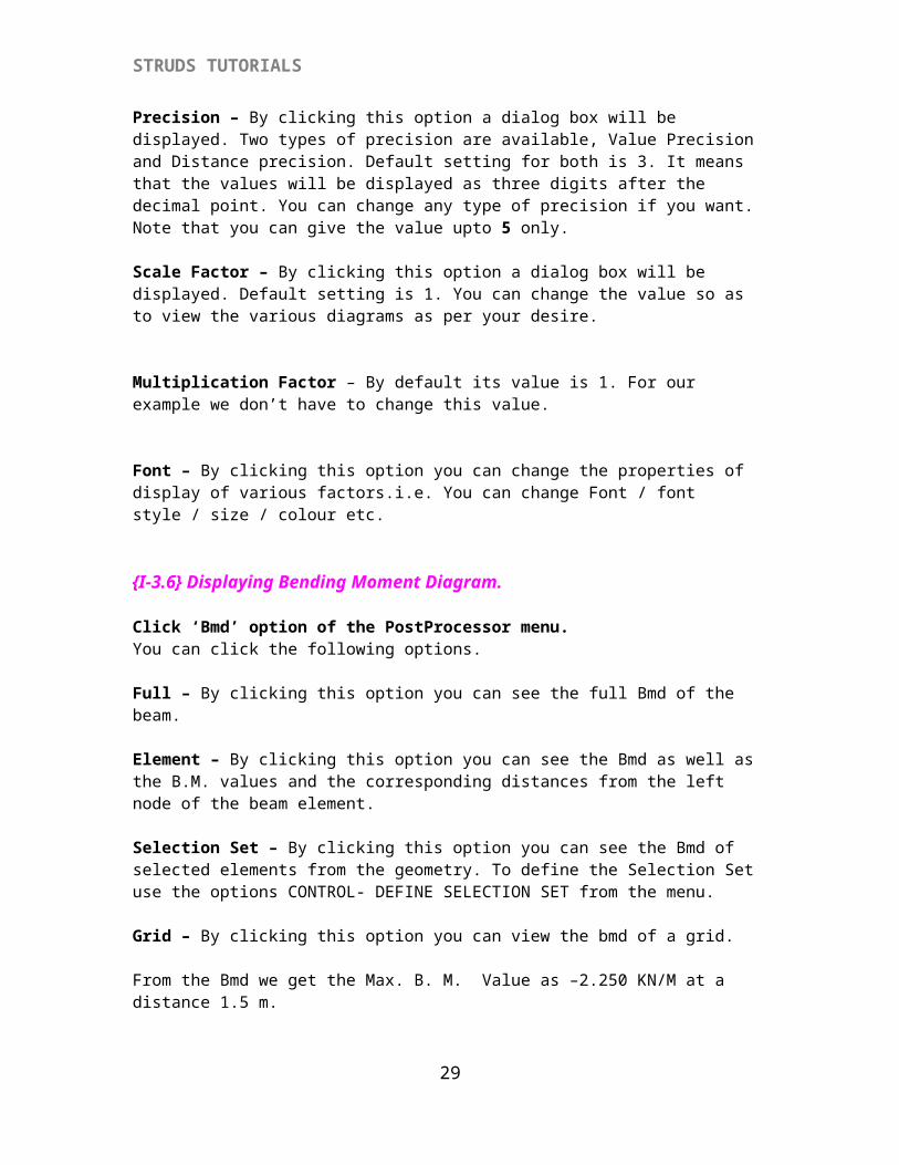
{I-3.6} Displaying Bending Moment Diagram.
Click ‘Bmd’ option of the PostProcessor menu.You can click the following options.
Full – By clicking this option you can see the full Bmd of the beam.
Element – By clicking this option you can see the Bmd as well as the B.M. values and the corresponding distances from the left node of the beam element.
Selection Set – By clicking this option you can see the Bmd of selected elements from the geometry. To define the Selection Set use the options CONTROL- DEFINE SELECTION SET from the menu.
Grid – By clicking this option you can view the bmd of a grid.
From the Bmd we get the Max. B. M. Value as –2.250 KN/M at a distance 1.5 m.
28
STRUDS TUTORIALS
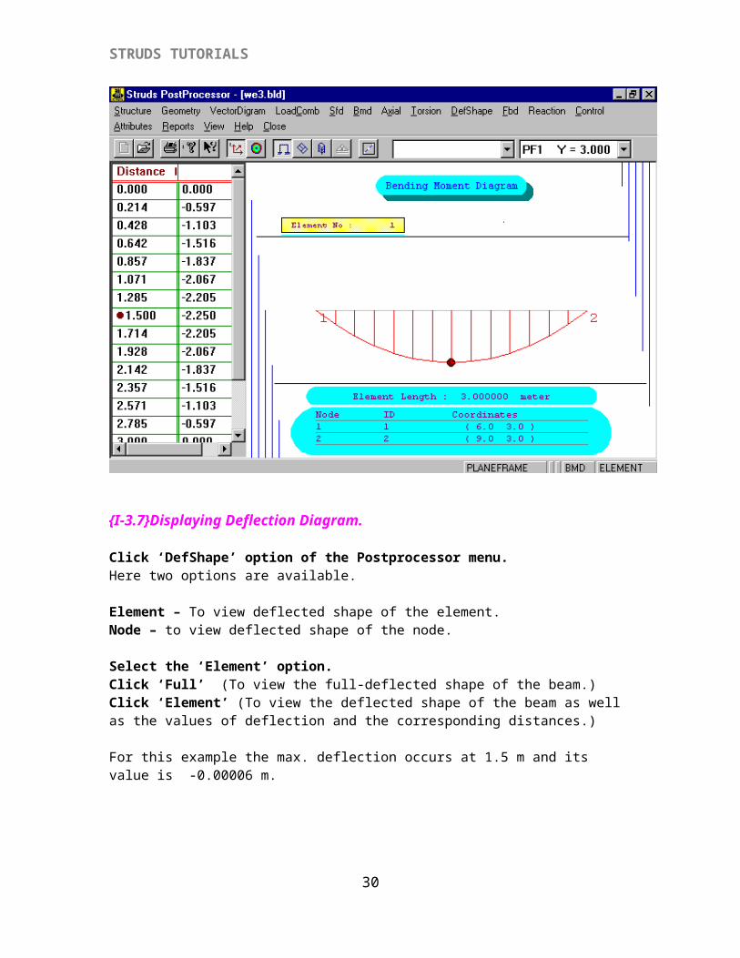
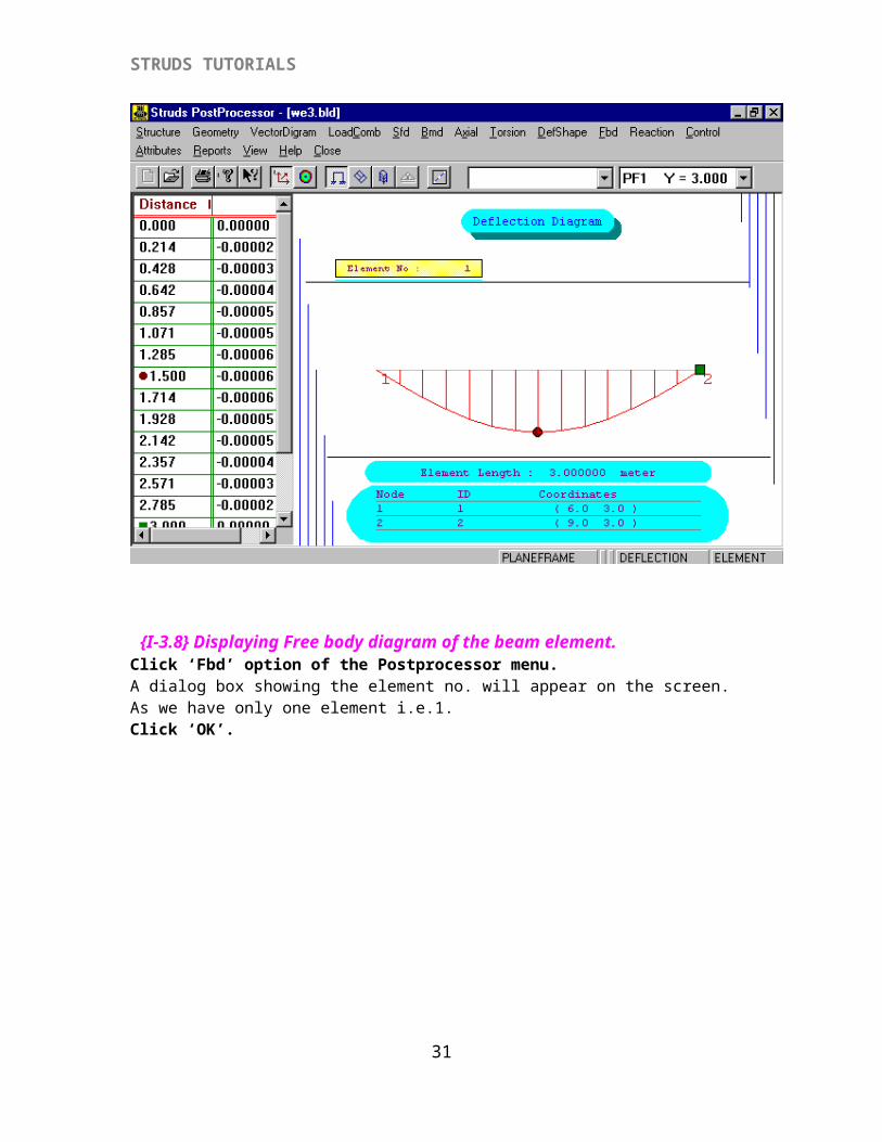
{I-3.7}Displaying Deflection Diagram.
Click ‘DefShape’ option of the Postprocessor menu.Here two options are available.
Element – To view deflected shape of the element.Node – to view deflected shape of the node.
Select the ‘Element’ option.Click ‘Full’ (To view the full-deflected shape of the beam.)Click ‘Element’ (To view the deflected shape of the beam as well as the values of deflection and the corresponding distances.)
For this example the max. deflection occurs at 1.5 m and its value is -0.00006 m.
{I-3.8} Displaying Free body diagram of the beam element.Click ‘Fbd’ option of the Postprocessor menu.A dialog box showing the element no. will appear on the screen. As we have only one element i.e.1. Click ‘OK’.
29
STRUDS TUTORIALS
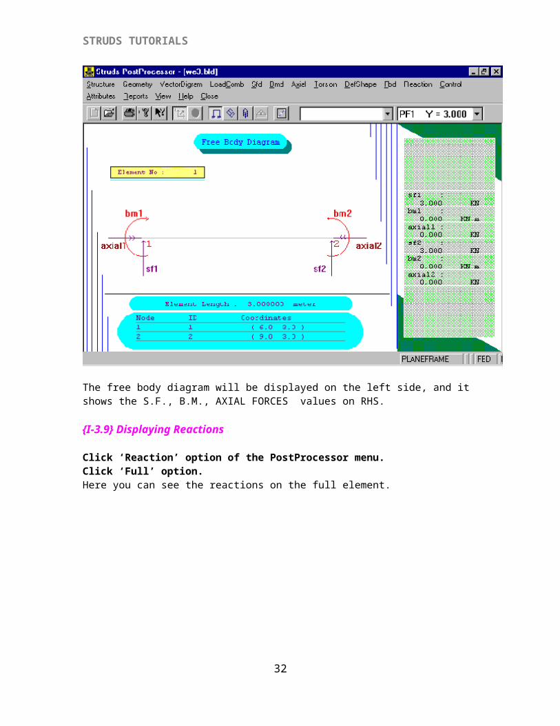
The free body diagram will be displayed on the left side, and it shows the S.F., B.M., AXIAL FORCES values on RHS.
{I-3.9} Displaying Reactions
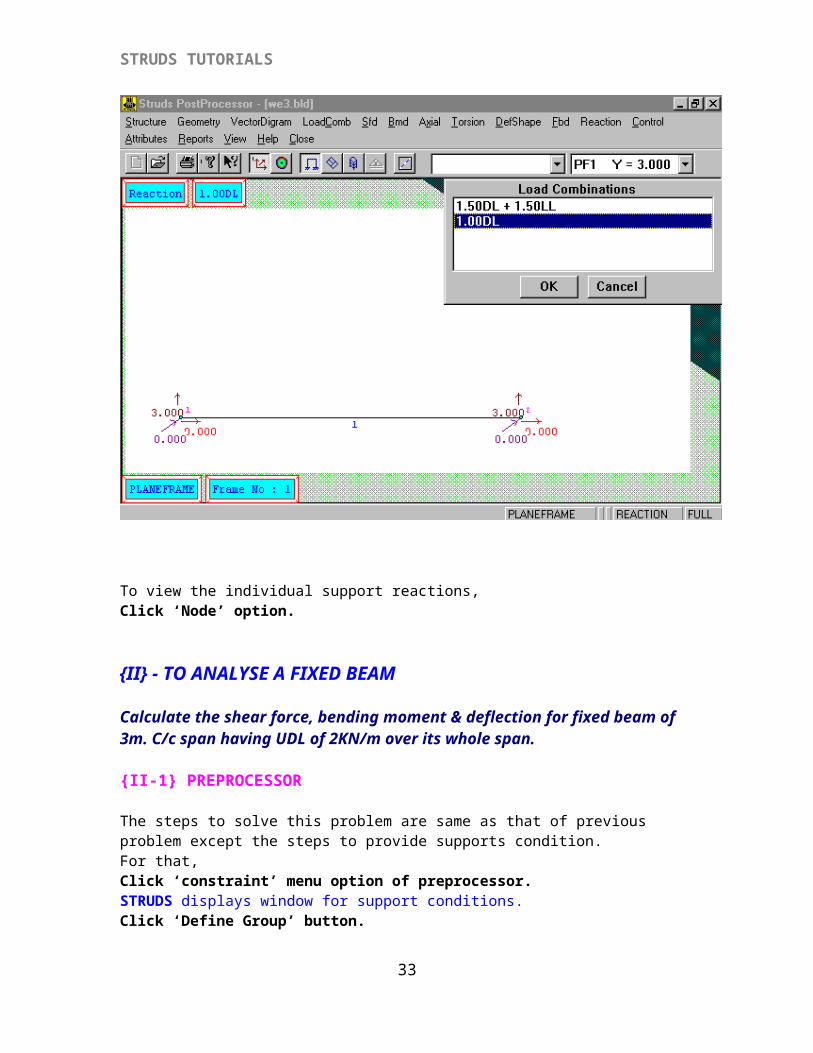
Click ‘Reaction’ option of the PostProcessor menu.Click ‘Full’ option.Here you can see the reactions on the full element.
30
STRUDS TUTORIALS
To view the individual support reactions,Click ‘Node’ option.
{II} - TO ANALYSE A FIXED BEAM
Calculate the shear force, bending moment & deflection for fixed beam of 3m. C/c span having UDL of 2KN/m over its whole span.
{II-1} PREPROCESSOR
The steps to solve this problem are same as that of previous problem except the steps to provide supports condition. For that,Click ‘constraint’ menu option of preprocessor.STRUDS displays window for support conditions.Click ‘Define Group’ button.
31
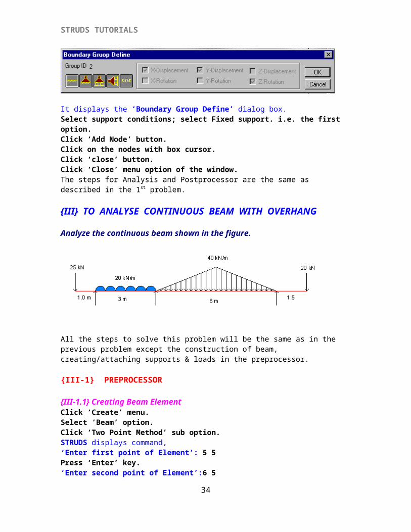
STRUDS TUTORIALS
It displays the ‘Boundary Group Define’ dialog box.Select support conditions; select Fixed support. i.e. the first option.Click ‘Add Node’ button.Click on the nodes with box cursor.Click ‘close’ button.Click ‘Close’ menu option of the window.The steps for Analysis and Postprocessor are the same as described in the 1st problem.
{III} TO ANALYSE CONTINUOUS BEAM WITH OVERHANG
Analyze the continuous beam shown in the figure.
All the steps to solve this problem will be the same as in the previous problem except the construction of beam, creating/attaching supports & loads in the preprocessor.
{III-1} PREPROCESSOR
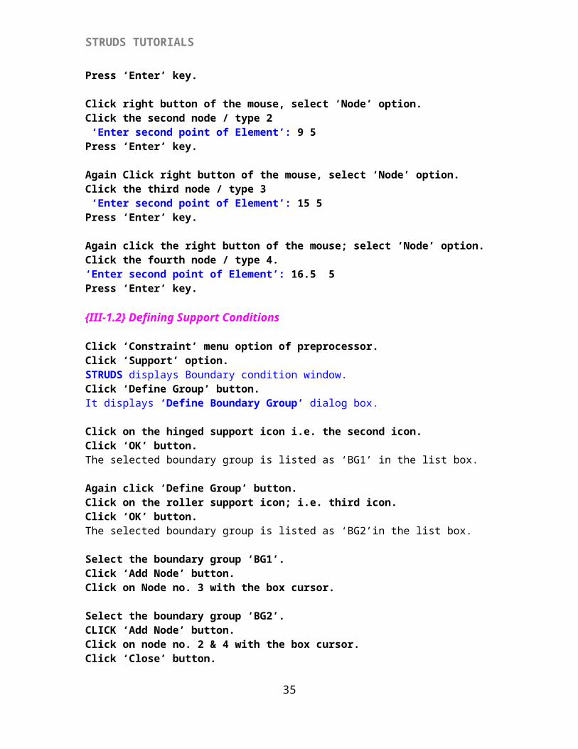
{III-1.1} Creating Beam ElementClick ‘Create’ menu.Select ‘Beam’ option.Click ‘Two Point Method’ sub option.STRUDS displays command,‘Enter first point of Element’: 5 5Press ‘Enter’ key.‘Enter second point of Element’:6 5Press ‘Enter’ key.
Click right button of the mouse, select ‘Node’ option.Click the second node / type 2 ‘Enter second point of Element’: 9 5Press ‘Enter’ key.
Again Click right button of the mouse, select ‘Node’ option.Click the third node / type 3
32
STRUDS TUTORIALS
‘Enter second point of Element’: 15 5Press ‘Enter’ key.
Again click the right button of the mouse; select ‘Node’ option.Click the fourth node / type 4.‘Enter second point of Element’: 16.5 5Press ‘Enter’ key.
{III-1.2} Defining Support Conditions
Click ‘Constraint’ menu option of preprocessor.Click ‘Support’ option.STRUDS displays Boundary condition window.Click ‘Define Group’ button.It displays ‘Define Boundary Group’ dialog box.
Click on the hinged support icon i.e. the second icon.Click ‘OK’ button.The selected boundary group is listed as ‘BG1’ in the list box.
Again click ‘Define Group’ button.Click on the roller support icon; i.e. third icon.Click ‘OK’ button. The selected boundary group is listed as ‘BG2’in the list box.
Select the boundary group ‘BG1’.Click ‘Add Node’ button.Click on Node no. 3 with the box cursor.
Select the boundary group ‘BG2’.CLICK ‘Add Node’ button.Click on node no. 2 & 4 with the box cursor.Click ‘Close’ button.
{III-1.3} Creating and Attaching Loads To The Beam Element
Click ‘Property’ menu option.Select ‘Create’ option.Select ‘Load’ option.Click ‘Elemental Load’ option.STRUDS displays ‘Define Load’ dialog box.
Click drop down arrow of load types.Select load type; Point Load.Key in load value 25 KN in the W-field appeared.Also key in the offset 0 m. in the A-field. In the angle field, key in the value of angle of application of the load. In this case the load is vertical hence the angle is 90Deg. If we don’t change it STRUDS will take it, by default as 90Deg.Click ‘Save’ button.The selected load type is listed as G1.
33
STRUDS TUTORIALS
Click ‘Drop down arrow’ of load types again.Select load type; Full UDLKey in load value 20 kN/m in the field appeared.Click ‘Save’ button.The selected load type is listed as G2 in the list box.
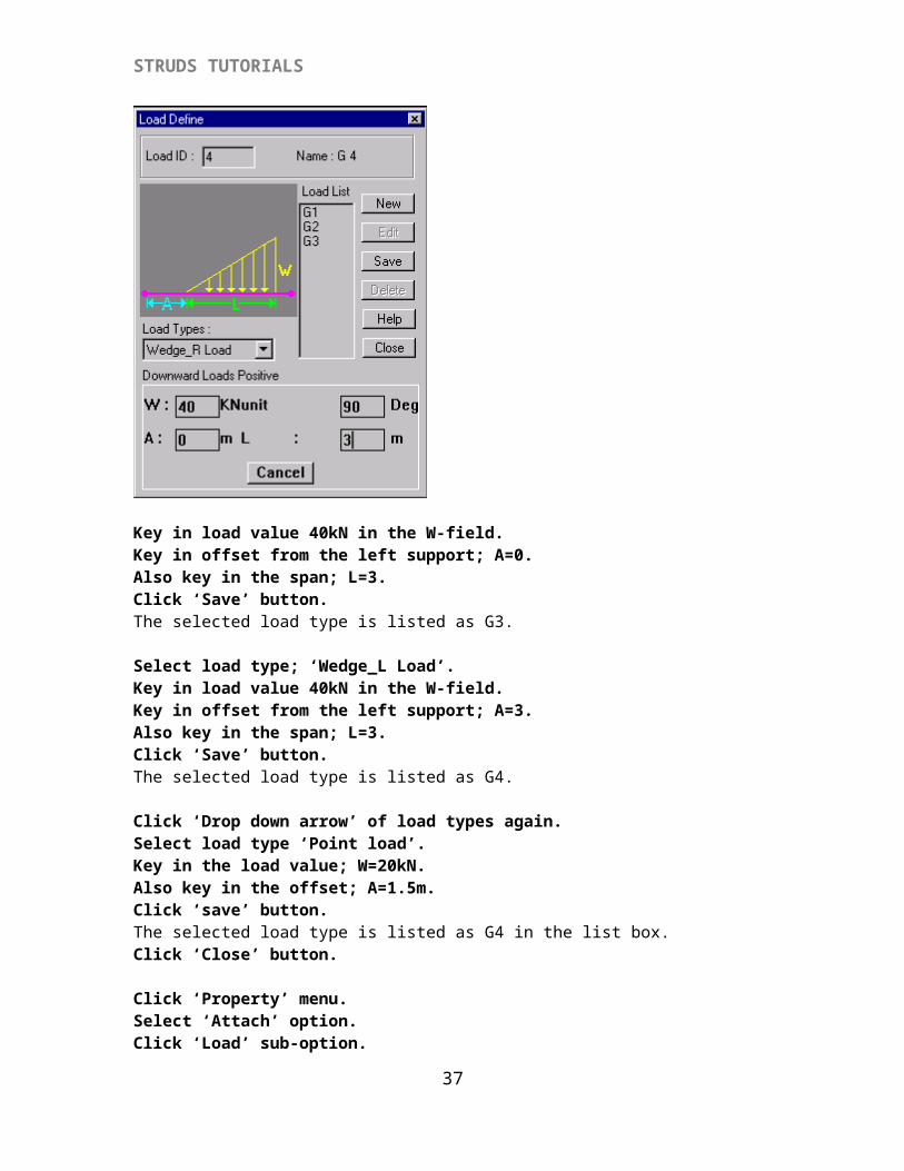
Click drop down arrow of load types again.Select load type; ‘Wedge_R Load’.
Key in load value 40kN in the W-field.Key in offset from the left support; A=0.Also key in the span; L=3.Click ‘Save’ button.The selected load type is listed as G3.
Select load type; ‘Wedge_L Load’.Key in load value 40kN in the W-field.Key in offset from the left support; A=3.Also key in the span; L=3.Click ‘Save’ button.The selected load type is listed as G4.
Click ‘Drop down arrow’ of load types again.Select load type ‘Point load’.Key in the load value; W=20kN.Also key in the offset; A=1.5m.Click ‘save’ button.The selected load type is listed as G4 in the list box.Click ‘Close’ button.
34
STRUDS TUTORIALS
Click ‘Property’ menu.Select ‘Attach’ option.Click ‘Load’ sub-option.STRUDS displays ‘Attach to Element’ dialog box. Select Load Group, G1.Click ‘Locate’ button.Click on the first element with box cursor.Select load group; G2.
Click on the second element with the box cursor.Select Load Group, G3.Click ‘Locate’ button.
Click on the third element with box cursor.Select load group; G4.Click on the third element with the box cursor.A message appears as ‘Element Already Loaded Under Some Category! Attach Load Again?’Click ‘Yes’ button.
Select load group; G5.Click on the fourth element with the box cursor.Click ‘Close’ button.
The rest of the steps are same as the previous problem.
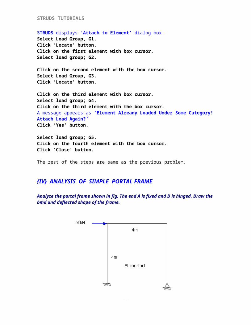
{IV} ANALYSIS OF SIMPLE PORTAL FRAME
Analyze the portal frame shown in fig. The end A is fixed and D is hinged. Draw the bmd and deflected shape of the frame.
35
STRUDS TUTORIALS
{IV-1} PREPROCESSOR
{IV-1.1} Creation Of The Portal FrameAll the previous steps are the same as given in the 1st problem except the construction procedure.Click ‘Create’ menu.Select ‘Column’ option.Click ‘Two point’ option.
‘Enter first point of Element’: 3 2Press ‘Enter’ key.‘Enter second point of Element’: 3 6Press ‘Enter’ key.
‘Enter first point of Element’: 7 2Press ‘Enter’ key.‘Enter second point of Element’: 7 6Press ‘Enter’ key.
Click ‘Create’ menu.Select ‘Beam’ option.Click ‘Two Point Method’ sub option.STRUDS displays command,‘Enter first point of Element’: 3 6Press ‘Enter’ key.‘Enter second point of Element’: 7 6Press ‘Enter’ key.
{IV-1.2} Defining The Support Conditions
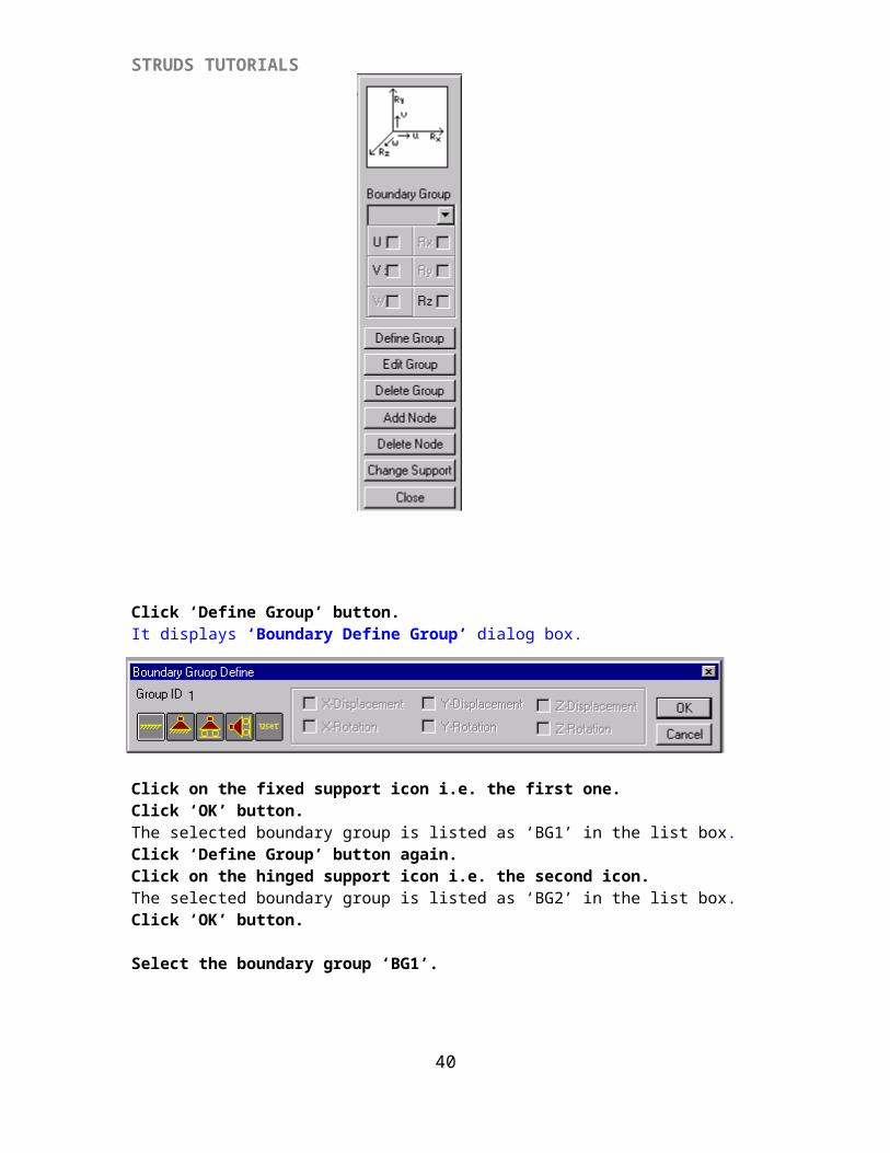
Click ‘Constraint’ menu option of preprocessor.Click ‘Support’ option.STRUDS displays Boundary condition window.
36
STRUDS TUTORIALS
Click ‘Define Group’ button.It displays ‘Boundary Define Group’ dialog box.
Click on the fixed support icon i.e. the first one.Click ‘OK’ button.The selected boundary group is listed as ‘BG1’ in the list box.Click ‘Define Group’ button again.Click on the hinged support icon i.e. the second icon.The selected boundary group is listed as ‘BG2’ in the list box.Click ‘OK’ button.
Select the boundary group ‘BG1’.
37
STRUDS TUTORIALS
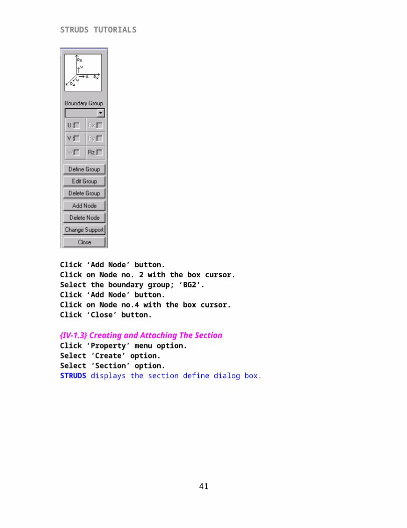
Click ‘Add Node’ button.Click on Node no. 2 with the box cursor.Select the boundary group; ‘BG2’.Click ‘Add Node’ button.Click on Node no.4 with the box cursor.Click ‘Close’ button.
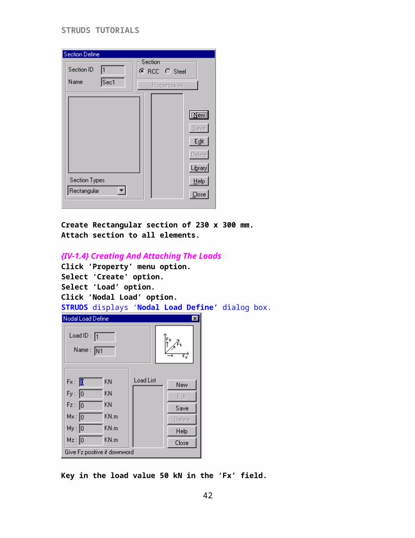
{IV-1.3} Creating and Attaching The SectionClick ‘Property’ menu option.Select ‘Create’ option.Select ‘Section’ option.STRUDS displays the section define dialog box.
38
STRUDS TUTORIALS
Create Rectangular section of 230 x 300 mm.Attach section to all elements.
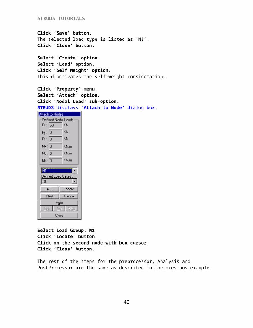
{IV-1.4} Creating And Attaching The LoadsClick ‘Property’ menu option.Select ‘Create’ option.Select ‘Load’ option.Click ‘Nodal Load’ option.STRUDS displays ‘Nodal Load Define’ dialog box.
Key in the load value 50 kN in the ‘Fx’ field.Click ‘Save’ button.The selected load type is listed as ‘N1’.Click ‘Close’ button.
39
STRUDS TUTORIALS
Select ‘Create’ option.Select ‘Load’ option.Click ‘Self Weight’ option.This deactivates the self-weight consideration.
Click ‘Property’ menu.Select ‘Attach’ option.Click ‘Nodal Load’ sub-option.STRUDS displays ‘Attach to Node’ dialog box.
Select Load Group, N1.Click ‘Locate’ button.Click on the second node with box cursor.Click ‘Close’ button.
The rest of the steps for the preprocessor, Analysis and PostProcessor are the same as described in the previous example.
40
STRUDS TUTORIALS
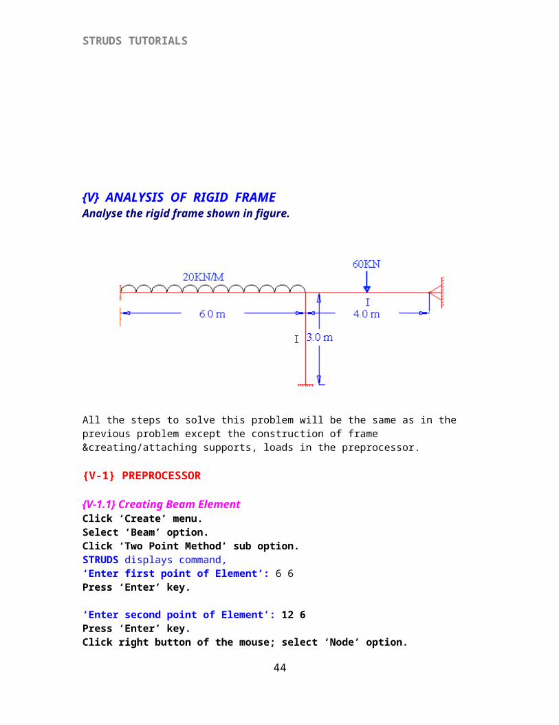
{V} ANALYSIS OF RIGID FRAMEAnalyse the rigid frame shown in figure.
All the steps to solve this problem will be the same as in the previous problem except the construction of frame &creating/attaching supports, loads in the preprocessor.
{V-1} PREPROCESSOR
{V-1.1} Creating Beam ElementClick ‘Create’ menu.Select ‘Beam’ option.Click ‘Two Point Method’ sub option.STRUDS displays command,‘Enter first point of Element’: 6 6 Press ‘Enter’ key.
‘Enter second point of Element’: 12 6Press ‘Enter’ key.Click right button of the mouse; select ‘Node’ option.Click the second node / type 2 ‘Enter second point of Element’: 16 6Press ‘Enter’ key.
Click ‘Create’ menu option.Select ‘Column’ option.Click ‘Two point’ option.‘Enter first point of Element’: 12 3Press ‘Enter’ key.
‘Enter second point of Element’: 12 6Press ‘Enter’ key.
41
STRUDS TUTORIALS
{V-1.2} Defining Support Condition
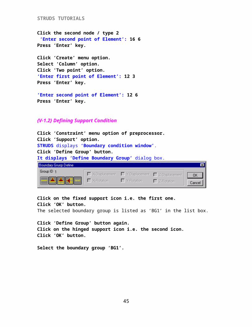
Click ‘Constraint’ menu option of preprocessor.Click ‘Support’ option.STRUDS displays ‘Boundary condition window’.Click ‘Define Group’ button.It displays ‘Define Boundary Group’ dialog box.
Click on the fixed support icon i.e. the first one.Click ‘OK’ button.The selected boundary group is listed as ‘BG1’ in the list box.
Click ‘Define Group’ button again.Click on the hinged support icon i.e. the second icon.Click ‘OK’ button.
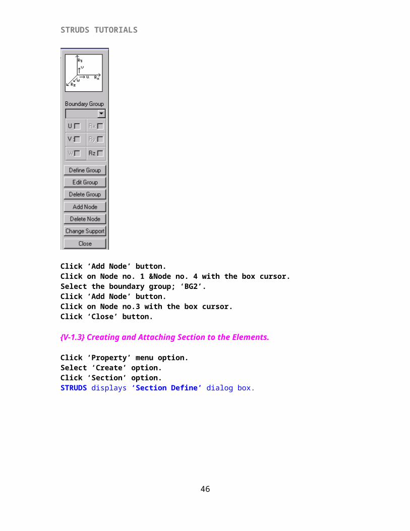
Select the boundary group ‘BG1’.
Click ‘Add Node’ button.Click on Node no. 1 &Node no. 4 with the box cursor.
42
STRUDS TUTORIALS
Select the boundary group; ‘BG2’.Click ‘Add Node’ button.Click on Node no.3 with the box cursor.Click ‘Close’ button.
{V-1.3} Creating and Attaching Section to the Elements.
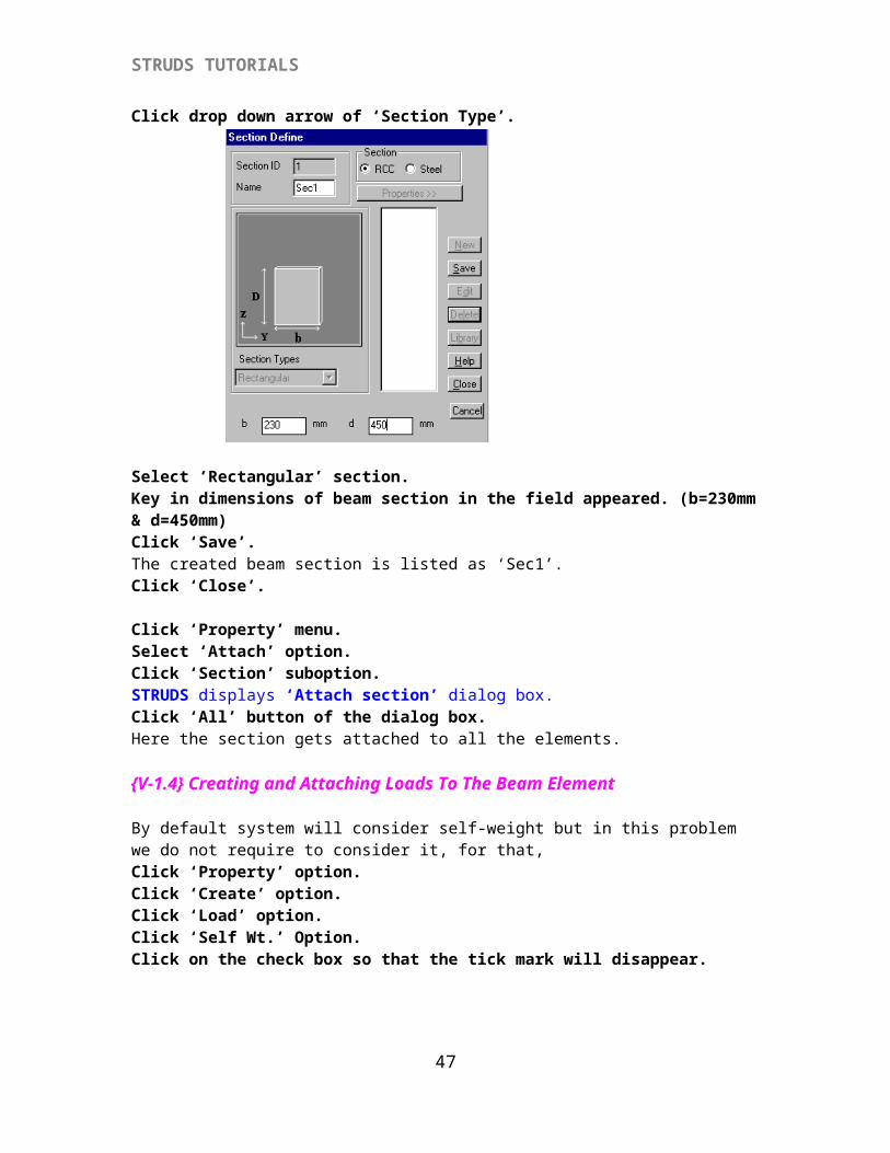
Click ‘Property’ menu option.Select ‘Create’ option.Click ‘Section’ option.STRUDS displays ‘Section Define’ dialog box.
Click drop down arrow of ‘Section Type’.
Select ‘Rectangular’ section.Key in dimensions of beam section in the field appeared. (b=230mm & d=450mm)Click ‘Save’.The created beam section is listed as ‘Sec1’.Click ‘Close’.
Click ‘Property’ menu.Select ‘Attach’ option.Click ‘Section’ suboption.STRUDS displays ‘Attach section’ dialog box.Click ‘All’ button of the dialog box.Here the section gets attached to all the elements.
{V-1.4} Creating and Attaching Loads To The Beam Element
By default system will consider self-weight but in this problem we do not require to consider it, for that,Click ‘Property’ option.Click ‘Create’ option.
43
STRUDS TUTORIALS
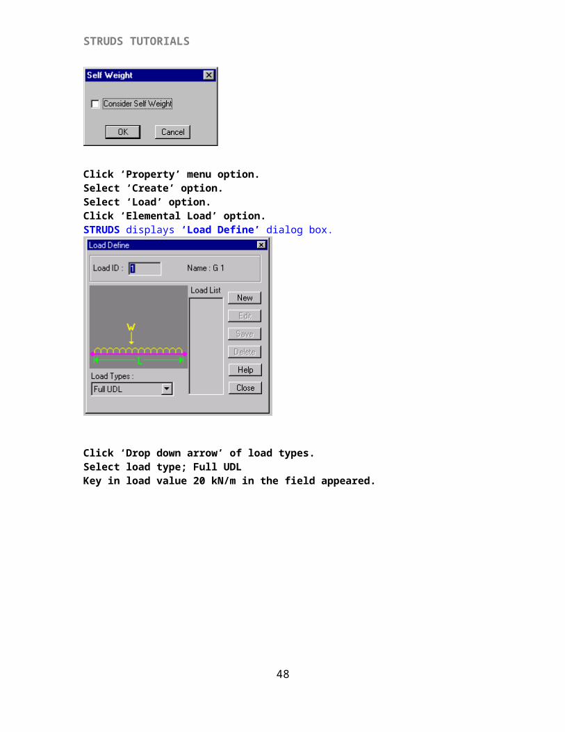
Click ‘Load’ option.Click ‘Self Wt.’ Option.Click on the check box so that the tick mark will disappear.
Click ‘Property’ menu option.Select ‘Create’ option.Select ‘Load’ option.Click ‘Elemental Load’ option.STRUDS displays ‘Load Define’ dialog box.
Click ‘Drop down arrow’ of load types.Select load type; Full UDLKey in load value 20 kN/m in the field appeared.
44
STRUDS TUTORIALS
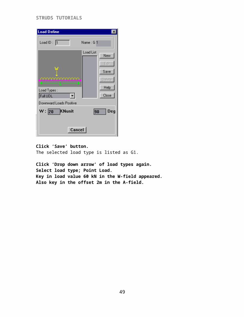
Click ‘Save’ button.The selected load type is listed as G1.
Click ‘Drop down arrow’ of load types again.Select load type; Point Load.Key in load value 60 kN in the W-field appeared.Also key in the offset 2m in the A-field.
45
STRUDS TUTORIALS
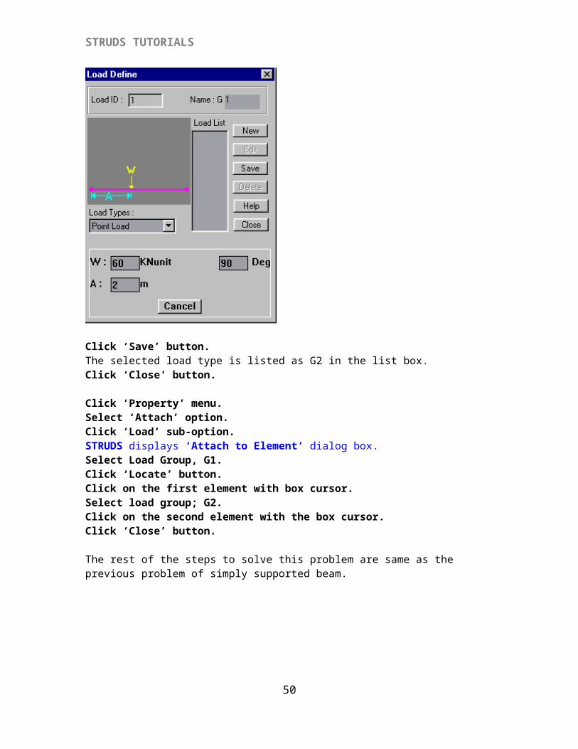
Click ‘Save’ button.The selected load type is listed as G2 in the list box.Click ‘Close’ button. Click ‘Property’ menu.Select ‘Attach’ option.Click ‘Load’ sub-option.STRUDS displays ‘Attach to Element’ dialog box. Select Load Group, G1.Click ‘Locate’ button.Click on the first element with box cursor.Select load group; G2.Click on the second element with the box cursor.Click ‘Close’ button.
The rest of the steps to solve this problem are same as the previous problem of simply supported beam.
INDIVIDUAL DESIGN MODULE
{VI} DESIGN OF ONE – WAY SLAB
Design a Simply Supported Slab Of 3m X 6m c/c.
To design this slab we will use the individual module of design.
For this, select the ‘Design’ option of the STRUDS control menu.Click ‘Stand Alone Design’ option.STRUDS displays a design option window for individual design of slab / beam / column.
{VI-1.1} Creating Slab
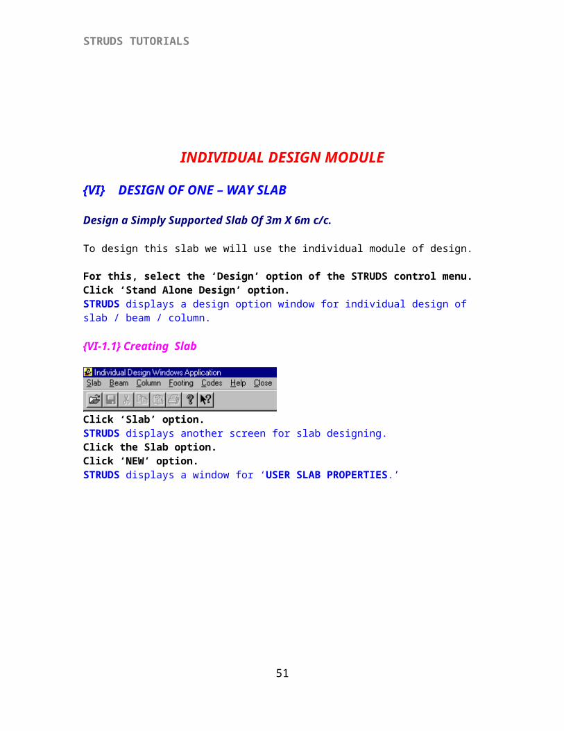
Click ‘Slab’ option.STRUDS displays another screen for slab designing.
46
STRUDS TUTORIALS
Click the Slab option.Click ‘NEW’ option.STRUDS displays a window for ‘USER SLAB PROPERTIES.’
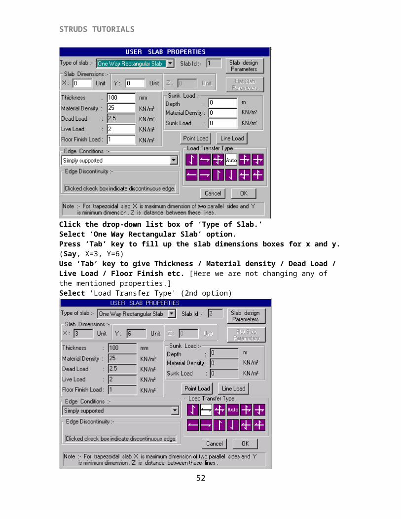
Click the drop-down list box of ‘Type of Slab.’Select ‘One Way Rectangular Slab’ option.Press ‘Tab’ key to fill up the slab dimensions boxes for x and y. (Say, X=3, Y=6)Use ‘Tab’ key to give Thickness / Material density / Dead Load / Live Load / Floor Finish etc. [Here we are not changing any of the mentioned properties.]Select 'Load Transfer Type' (2nd option)
47
STRUDS TUTORIALS
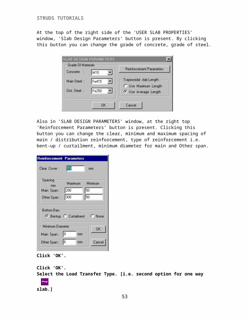
At the top of the right side of the ‘USER SLAB PROPERTIES’ window, ‘Slab Design Parameters’ button is present. By clicking this button you can change the grade of concrete, grade of steel.
Also in ‘SLAB DESIGN PARAMETERS’ window, at the right top ‘Reinforcement Parameters’ button is present. Clicking this button you can change the clear, minimum and maximum spacing of main / distribution reinforcement, type of reinforcement i.e. bent-up / curtailment, minimum diameter for main and Other span.
48
STRUDS TUTORIALS
Click ‘OK’.
Click ‘OK’.Select the Load Transfer Type. [i.e. second option for one way slab.]
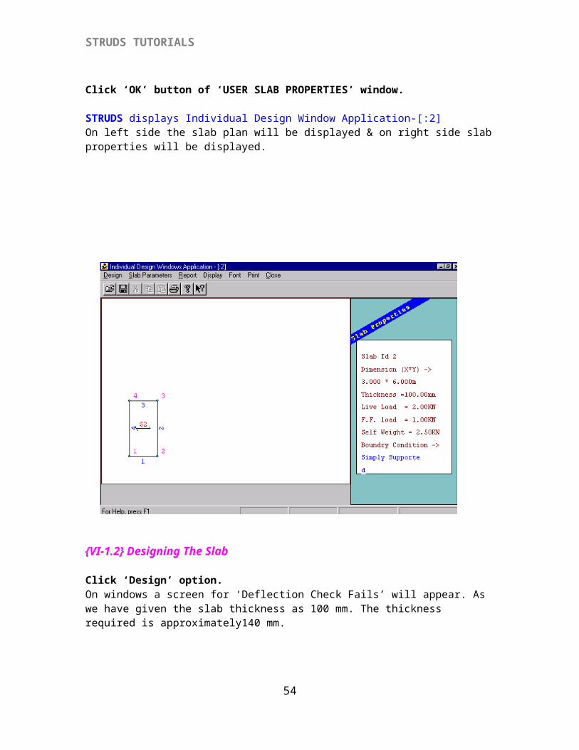
Click ‘OK’ button of ‘USER SLAB PROPERTIES’ window.
STRUDS displays Individual Design Window Application-[:2]On left side the slab plan will be displayed & on right side slab properties will be displayed.
49
STRUDS TUTORIALS
{VI-1.2} Designing The Slab
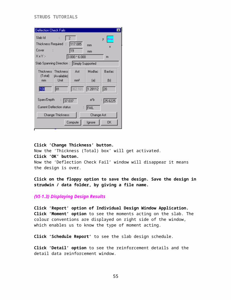
Click ‘Design’ option.On windows a screen for ‘Deflection Check Fails’ will appear. As we have given the slab thickness as 100 mm. The thickness required is approximately140 mm.
50
STRUDS TUTORIALS
Click ‘Change Thickness’ button.Now the ‘Thickness (Total) box’ will get activated.Click ‘OK’ button.Now the ‘Deflection Check Fail’ window will disappear it means the design is over.
Click on the floppy option to save the design. Save the design in strudwin / data folder, by giving a file name.
{VI-1.3} Displaying Design Results
Click ‘Report’ option of Individual Design Window Application.Click ‘Moment’ option to see the moments acting on the slab. The colour conventions are displayed on right side of the window, which enables us to know the type of moment acting.
Click ‘Schedule Report’ to see the slab design schedule.
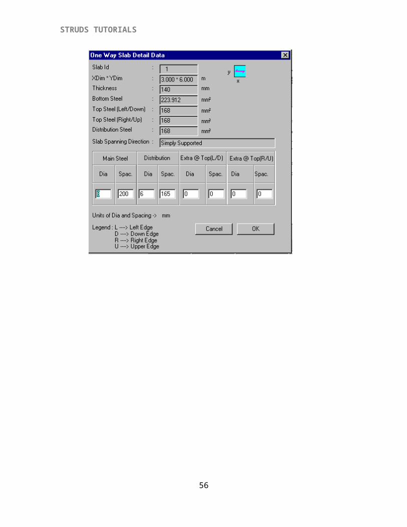
Click ‘Detail’ option to see the reinforcement details and the detail data reinforcement window.
51
STRUDS TUTORIALS
52
STRUDS TUTORIALS
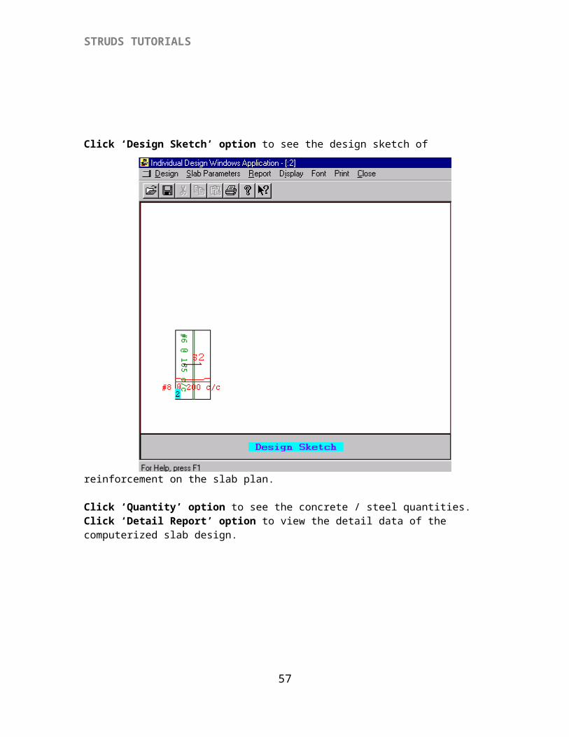
Click ‘Design Sketch’ option to see the design sketch of reinforcement on the slab plan.
Click ‘Quantity’ option to see the concrete / steel quantities.Click ‘Detail Report’ option to view the detail data of the computerized slab design.
53
STRUDS TUTORIALS
{VII} DESIGN OF BEAM
Design a singly reinforced beam of length 4m, carrying a UDL of 15kN. Select ‘Stand Alone Design’ option of the Design menu from the STRUDS main window. STRUDS displays Individual Design Window Application.
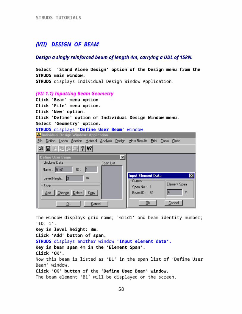
{VII-1.1} Inputting Beam Geometry Click ‘Beam’ menu optionClick ‘File’ menu option.Click ‘New’ option.Click ‘Define’ option of Individual Design Window menu.Select ‘Geometry’ option.STRUDS displays ‘Define User Beam’ window.
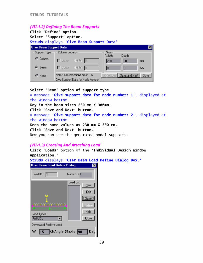
The window displays grid name; ‘Grid1’ and beam identity number; ‘ID: 1'.Key in level height: 3m.Click ‘Add’ button of span.STRUDS displays another window ‘Input element data’.Key in beam span 4m in the ‘Element Span’.Click ‘OK’.Now this beam is listed as ‘B1’ in the span list of ‘Define User Beam’ window.Click ‘OK’ button of the ‘Define User Beam’ window.The beam element ‘B1’ will be displayed on the screen.{VII-1.2} Defining The Beam SupportsClick ‘Define’ option.Select ‘Support’ option.Struds displays ‘Give Beam Support Data’
54
STRUDS TUTORIALS
Select ‘Beam’ option of support type.A message ‘Give support data for node number: 1', displayed at the window bottom.Key in the beam sizes 230 mm X 300mm.Click ‘Save and Next’ button.A message ‘Give support data for node number: 2', displayed at the window bottom.Keep the same values as 230 mm X 300 mm.Click ‘Save and Next’ button.Now you can see the generated nodal supports.
{VII-1.3} Creating And Attaching Load Click ‘Loads’ option of the ‘Individual Design Window Application.’Struds displays ‘User Beam Load Define Dialog Box.’
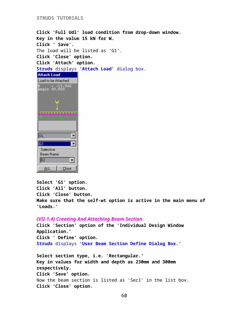
Click ‘Full Udl’ load condition from drop-down window.Key in the value 15 kN for W.Click ‘ Save’.The load will be listed as ‘G1’.Click ‘Close’ option.Click ‘Attach’ option.Struds displays ‘Attach Load’ dialog box.
55
STRUDS TUTORIALS
Select ‘G1’ option.Click ‘All’ button.Click ‘Close’ button.Make sure that the self-wt option is active in the main menu of ‘Loads.’
{VII-1.4} Creating And Attaching Beam SectionClick ‘Section’ option of the ‘Individual Design Window Application.’Click ‘ Define’ option.Struds displays ‘User Beam Section Define Dialog Box.’
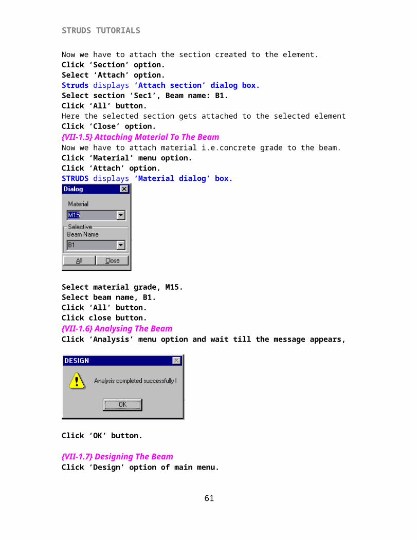
Select section type, i.e. ‘Rectangular.’Key in values for width and depth as 230mm and 300mm respectively.Click ‘Save’ option.Now the beam section is listed as ‘Sec1’ in the list box.Click ‘Close’ option.Now we have to attach the section created to the element.Click ‘Section’ option.Select ‘Attach’ option.Struds displays ‘Attach section’ dialog box.Select section ‘Sec1’, Beam name: B1.Click ‘All’ button.Here the selected section gets attached to the selected elementClick ‘Close’ option.{VII-1.5} Attaching Material To The BeamNow we have to attach material i.e.concrete grade to the beam.Click ‘Material’ menu option.Click ‘Attach’ option.STRUDS displays ‘Material dialog’ box.
56
STRUDS TUTORIALS
Select material grade, M15.Select beam name, B1.Click ‘All’ button.Click close button.{VII-1.6} Analysing The BeamClick ‘Analysis’ menu option and wait till the message appears,
Click ‘OK’ button.
{VII-1.7} Designing The BeamClick ‘Design’ option of main menu.
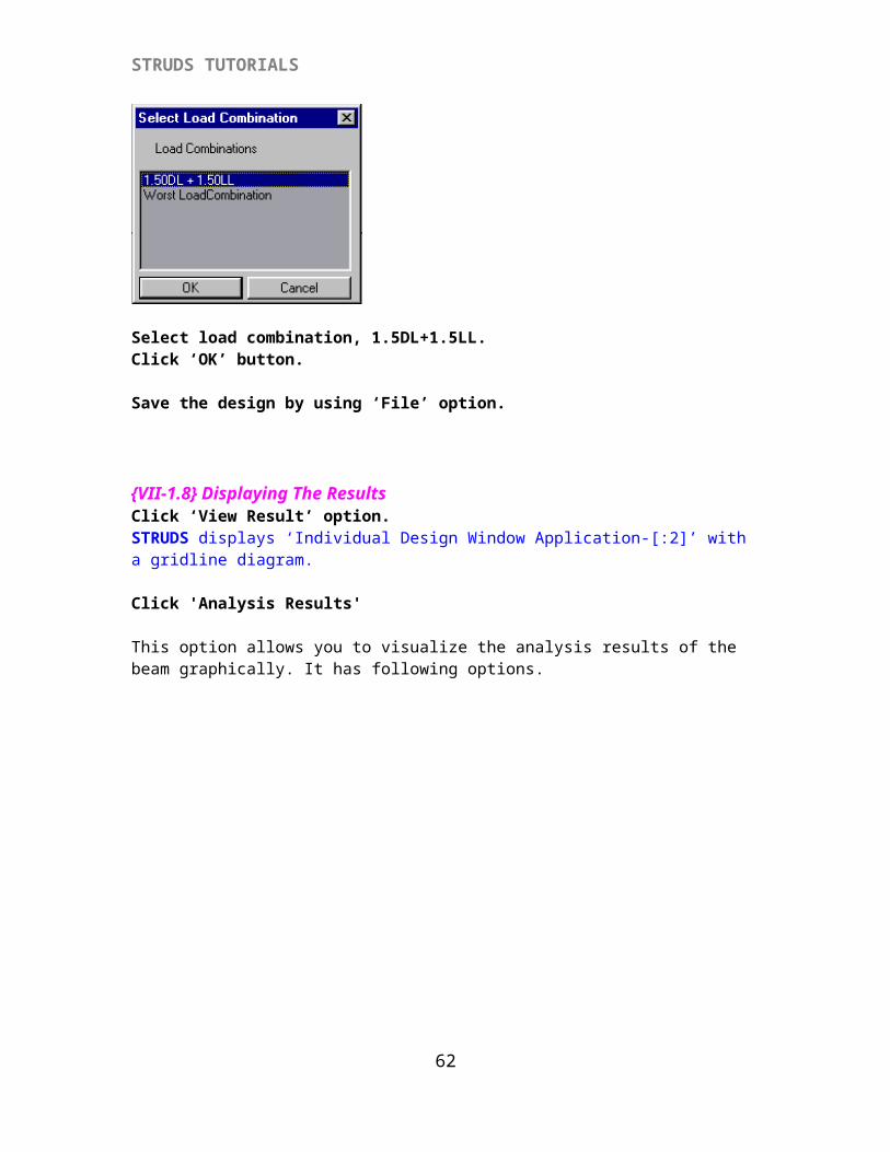
Select load combination, 1.5DL+1.5LL.Click ‘OK’ button.
Save the design by using ‘File’ option.
57
STRUDS TUTORIALS
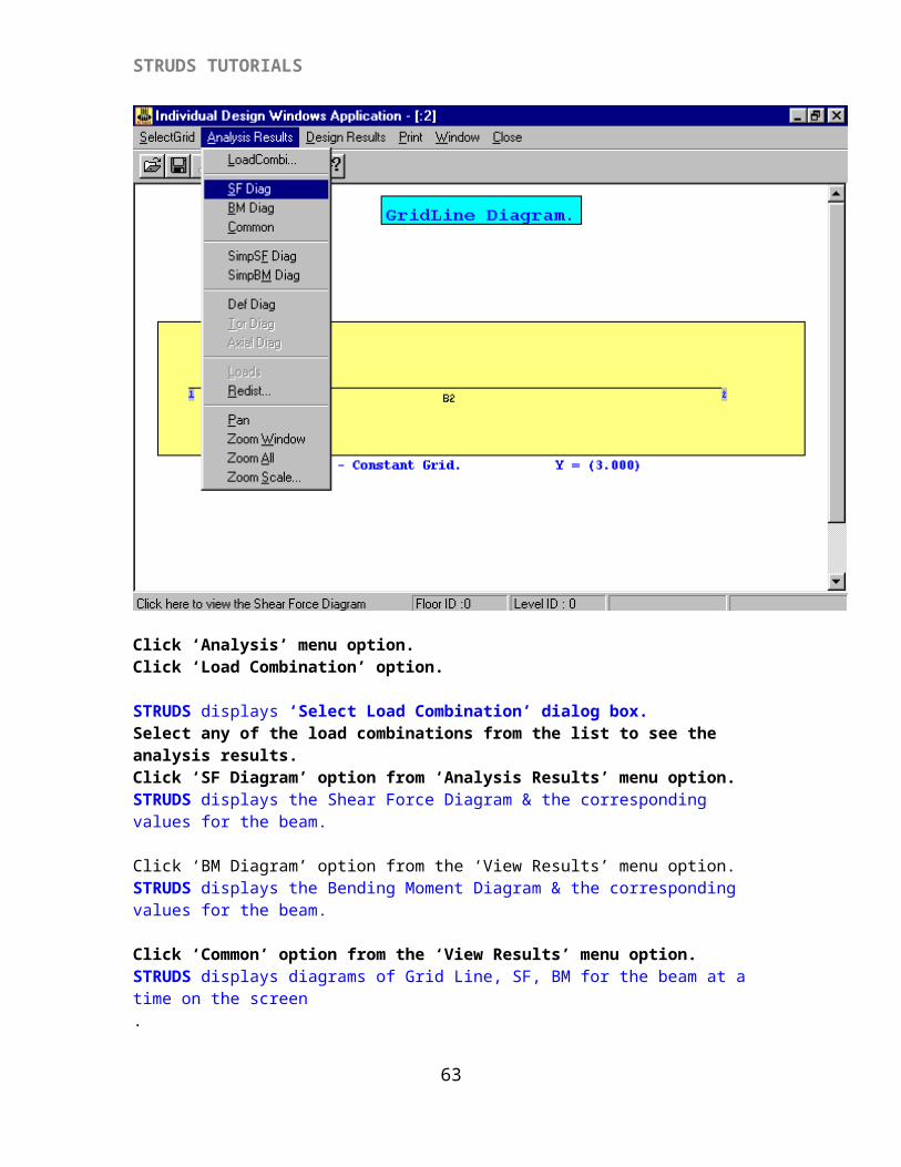
{VII-1.8} Displaying The ResultsClick ‘View Result’ option.STRUDS displays ‘Individual Design Window Application-[:2]’ with a gridline diagram.
Click 'Analysis Results'
This option allows you to visualize the analysis results of the beam graphically. It has following options.
Click ‘Analysis’ menu option.Click ‘Load Combination’ option.
STRUDS displays ‘Select Load Combination’ dialog box.Select any of the load combinations from the list to see the analysis results.Click ‘SF Diagram’ option from ‘Analysis Results’ menu option.STRUDS displays the Shear Force Diagram & the corresponding values for the beam.
Click ‘BM Diagram’ option from the ‘View Results’ menu option.STRUDS displays the Bending Moment Diagram & the corresponding values for the beam.
Click ‘Common’ option from the ‘View Results’ menu option.STRUDS displays diagrams of Grid Line, SF, BM for the beam at a time on the screen.Click 'Simple SF Diagram/ Simple BM Diagram’ from the ‘View Results’ menu option.
58
STRUDS TUTORIALS
STRUDS displays the SF Diagram/BM Diagram for the beam considering all the beams as simply supported.Click ‘Def diagram’ from the ‘View Results’ menu option.STRUDS displays the deflected shape diagram for the beam.
Click ‘Tor Diagram’ from the ‘View Results’ menu option.STRUDS displays the Torsional diagram for the beam.
Click ‘Loads’ option from the ‘View Results’ menu option.STRUDS displays the various loads acting on the beam in graphical form with values.
Click ‘Redist’ option from the ‘View Results’ menu option.STRUDS displays the ‘Redistribution’ window.Select the beam in the ‘Beam ID’ field.Key in the values of ‘Redistribution Factor’ for the left &right support.Click ‘Redistribute’ button. STRUDS displays the values of redistributed moments in the right part of the window.
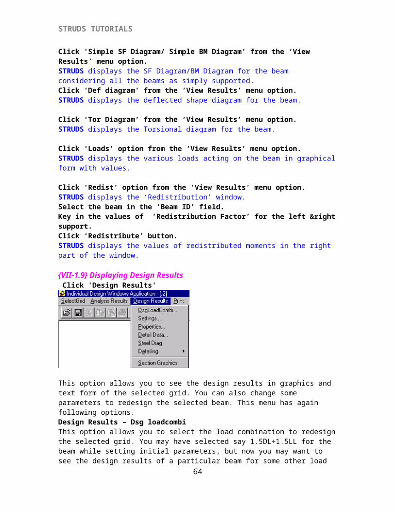
{VII-1.9} Displaying Design Results Click 'Design Results'
This option allows you to see the design results in graphics and text form of the selected grid. You can also change some parameters to redesign the selected beam. This menu has again following options.Design Results – Dsg loadcombiThis option allows you to select the load combination to redesign the selected grid. You may have selected say 1.5DL+1.5LL for the beam while setting initial parameters, but now you may want to see the design results of a particular beam for some other load combination, say for in such case, Worst Load Combination you can select the load combination and STRUDS will redesign the beam for the selected load combination.
When you select this option STRUDS displays following window.
59
STRUDS TUTORIALS
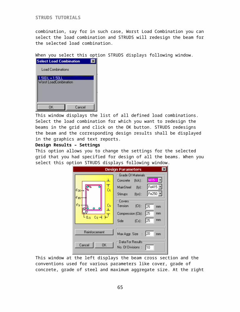
This window displays the list of all defined load combinations. Select the load combination for which you want to redesign the beams in the grid and click on the OK button. STRUDS redesigns the beam and the corresponding design results shall be displayed in the graphics and text reports. Design Results – SettingsThis option allows you to change the settings for the selected grid that you had specified for design of all the beams. When you select this option STRUDS displays following window.
This window at the left displays the beam cross section and the conventions used for various parameters like cover, grade of concrete, grade of steel and maximum aggregate size. At the right are the drop down menus and fields where you can specify the parameters by overwriting default values.Concrete (fck): At the right top is a drop down menu, which shows the various grades of concrete. Select the grade of concrete that you want to use for redesigning the beams.Main Steel (fy):The second drop down menu indicates the grades of steel available such as Fe250 – Mild Steel, Fe415 – Tor Steel, Fe500 – High Strength Tor Steel. Select the grade of steel that you want to use for the main reinforcement i.e. the longitudinal reinforcement at the top and bottom of beam from this drop down menu.Stirrups (fys):The third drop down menu indicates the grades of steel available such as Fe250 – Mild Steel, Fe415 – Tor Steel, Fe500 – High Strength Tor Steel. Select the grade of steel that you want to use for the stirrup reinforcement i.e. the vertical reinforcement along the beam in the form of rings.
60
STRUDS TUTORIALS
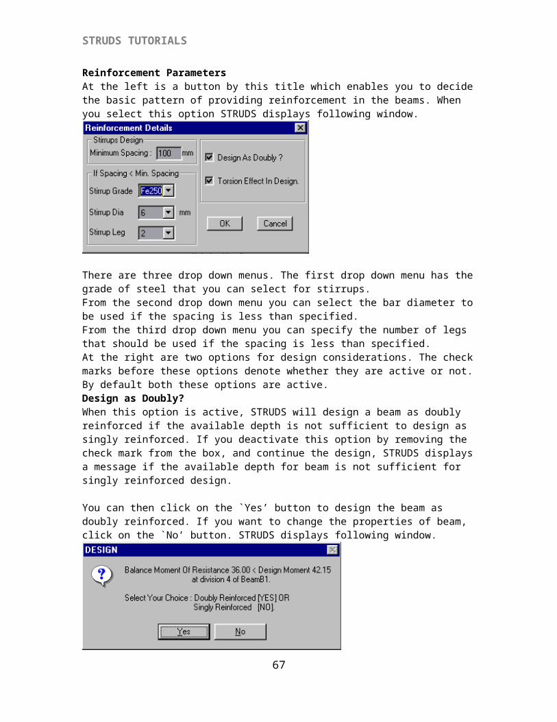
Below the drop down menus are three fields for specifying concrete covers.Tension (Ct):In this field type the value of clear cover you want to provide for bottom bars in the beam.Compression (Cb):In this field type the value of clear cover you want to provide for top bars in the beam.Side (Cs):In this field type the value of clear cover you want to provide for stirrups along the side face of the beam.Max Agg SIZE:This field denotes the maximum size of coarse aggregates in concrete that will decide the minimum spacing between bars. No. Of DIVISIONS:This field denotes the no. Of divisions in an element at which the design results are to be displayed. For analysis, STRUDS divides each element into 16 parts. For design you can consider the divisions equal to or less than 16. While preparing the reports for design, STRUDS will display the results as per the number of divisions specified by you.Reinforcement ParametersAt the left is a button by this title which enables you to decide the basic pattern of providing reinforcement in the beams. When you select this option STRUDS displays following window.
There are three drop down menus. The first drop down menu has the grade of steel that you can select for stirrups.From the second drop down menu you can select the bar diameter to be used if the spacing is less than specified.From the third drop down menu you can specify the number of legs that should be used if the spacing is less than specified.At the right are two options for design considerations. The check marks before these options denote whether they are active or not. By default both these options are active.Design as Doubly?When this option is active, STRUDS will design a beam as doubly reinforced if the available depth is not sufficient to design as singly reinforced. If you deactivate this option by removing the check mark from the box, and continue the design, STRUDS displays a message if the available depth for beam is not sufficient for singly reinforced design.
You can then click on the `Yes’ button to design the beam as doubly reinforced. If you want to change the properties of beam, click on the `No’ button. STRUDS displays following window.
61
STRUDS TUTORIALS
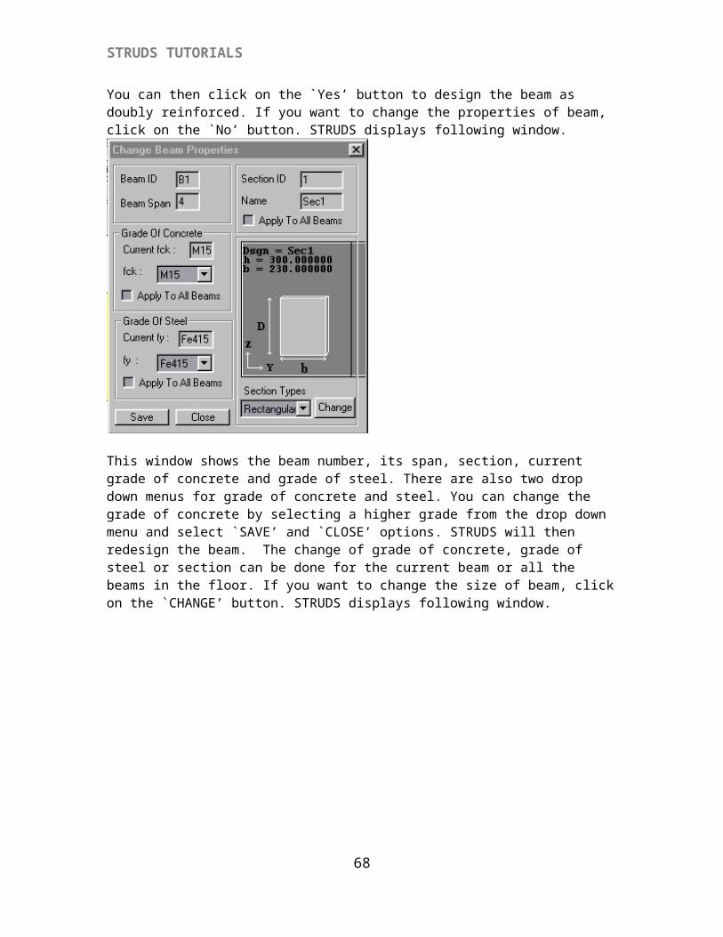
You can then click on the `Yes’ button to design the beam as doubly reinforced. If you want to change the properties of beam, click on the `No’ button. STRUDS displays following window.
This window shows the beam number, its span, section, current grade of concrete and grade of steel. There are also two drop down menus for grade of concrete and steel. You can change the grade of concrete by selecting a higher grade from the drop down menu and select `SAVE’ and `CLOSE’ options. STRUDS will then redesign the beam. The change of grade of concrete, grade of steel or section can be done for the current beam or all the beams in the floor. If you want to change the size of beam, click on the `CHANGE’ button. STRUDS displays following window.
62
STRUDS TUTORIALS
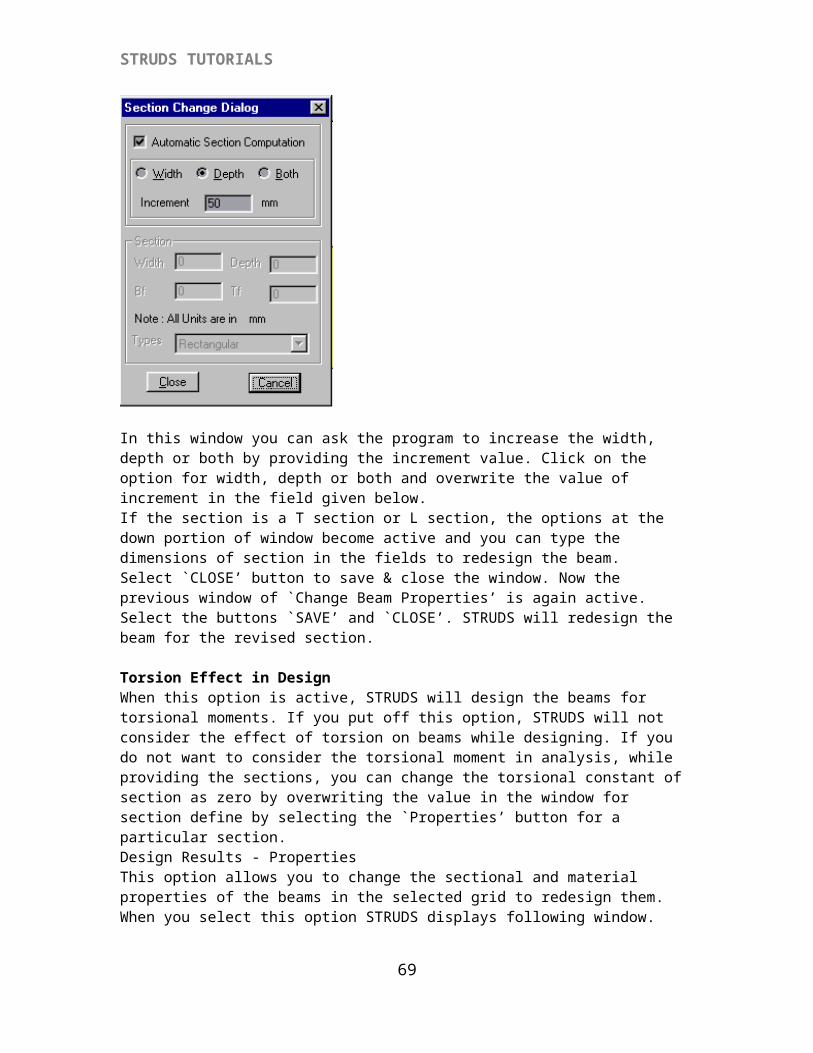
In this window you can ask the program to increase the width, depth or both by providing the increment value. Click on the option for width, depth or both and overwrite the value of increment in the field given below.If the section is a T section or L section, the options at the down portion of window become active and you can type the dimensions of section in the fields to redesign the beam.Select `CLOSE’ button to save & close the window. Now the previous window of `Change Beam Properties’ is again active. Select the buttons `SAVE’ and `CLOSE’. STRUDS will redesign the beam for the revised section.
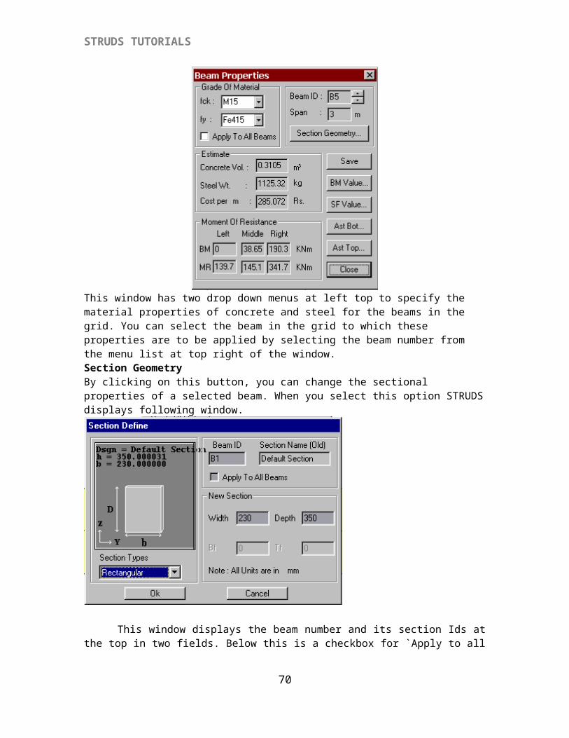
Torsion Effect in DesignWhen this option is active, STRUDS will design the beams for torsional moments. If you put off this option, STRUDS will not consider the effect of torsion on beams while designing. If you do not want to consider the torsional moment in analysis, while providing the sections, you can change the torsional constant of section as zero by overwriting the value in the window for section define by selecting the `Properties’ button for a particular section.Design Results - PropertiesThis option allows you to change the sectional and material properties of the beams in the selected grid to redesign them. When you select this option STRUDS displays following window.
63
STRUDS TUTORIALS
This window has two drop down menus at left top to specify the material properties of concrete and steel for the beams in the grid. You can select the beam in the grid to which these properties are to be applied by selecting the beam number from the menu list at top right of the window.Section GeometryBy clicking on this button, you can change the sectional properties of a selected beam. When you select this option STRUDS displays following window.
This window displays the beam number and its section Ids at the top in two fields. Below this is a checkbox for `Apply to all Beams’ option. You can click on this check box to apply the new section to all the beams in the selected grid.
At the left is the drop down menu from which you can select the new section type that you want to assign to the beam. At the right you can specify the values of width and depth of the new section. The options for Bf – width of flange and Tf – thickness of flange will be active if you have selected T or L section type. Click on the on the OK button to apply the new section. You can click on the CANCEL button to abandon the assigning of new section.
64
STRUDS TUTORIALS
Detail DataThis option allows you to change the bar-detailing pattern of the selected grid. When you select this option, STRUDS displays following window.
You can select the detailing type of bars as Bent Up, Curtailed or none of these by selecting the corresponding options in this window. If you select `None’ options; STRUDS will provide the maximum required steel at top and bottom uniformly without curtailing the bars.The window also has options for design considerations that can be put on off by selecting their check boxes.
Click on the OK button to save the detailing type and proceed for design. Select Cancel button if you want to consider the default detailing for design.
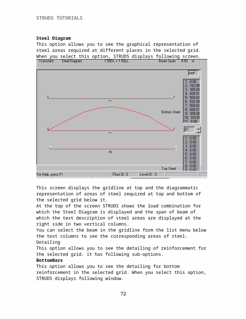
Steel DiagramThis option allows you to see the graphical representation of steel areas required at different places in the selected grid. When you select this option, STRUDS displays following screen.
65
STRUDS TUTORIALS
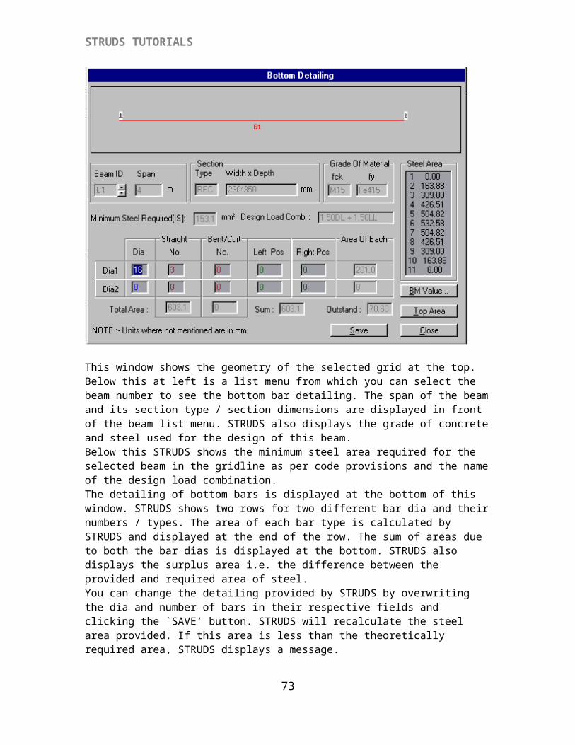
This screen displays the gridline at top and the diagrammatic representation of areas of steel required at top and bottom of the selected grid below it.At the top of the screen STRUDS shows the load combination for which the Steel Diagram is displayed and the span of beam of which the text description of steel areas are displayed at the right side in two vertical columns.You can select the beam in the gridline form the list menu below the text columns to see the corresponding areas of steel. DetailingThis option allows you to see the detailing of reinforcement for the selected grid. it has following sub-options.BottomBarsThis option allows you to see the detailing for bottom reinforcement in the selected grid. When you select this option, STRUDS displays following window.
66
STRUDS TUTORIALS
This window shows the geometry of the selected grid at the top. Below this at left is a list menu from which you can select the beam number to see the bottom bar detailing. The span of the beam and its section type / section dimensions are displayed in front of the beam list menu. STRUDS also displays the grade of concrete and steel used for the design of this beam. Below this STRUDS shows the minimum steel area required for the selected beam in the gridline as per code provisions and the name of the design load combination.The detailing of bottom bars is displayed at the bottom of this window. STRUDS shows two rows for two different bar dia and their numbers / types. The area of each bar type is calculated by STRUDS and displayed at the end of the row. The sum of areas due to both the bar dias is displayed at the bottom. STRUDS also displays the surplus area i.e. the difference between the provided and required area of steel.You can change the detailing provided by STRUDS by overwriting the dia and number of bars in their respective fields and clicking the `SAVE’ button. STRUDS will recalculate the steel area provided. If this area is less than the theoretically required area, STRUDS displays a message.You can then click on the OK button to provide your own steel area. These changes will automatically be reflected in design schedule and quantity reports by STRUDS.At the right side of window STRUDS displays the text values for the areas of steel required at eleven different places in the selected beam. Below it are two buttons for BM VALUES and TOP AREA.
BM VALUESWhen you select this button, STRUDS displays the bending moment values for the selected beam at eleven places.
67
STRUDS TUTORIALS
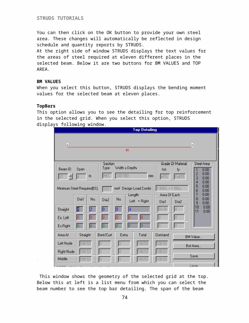
TopBarsThis option allows you to see the detailing for top reinforcement in the selected grid. When you select this option, STRUDS displays following window.
This window shows the geometry of the selected grid at the top. Below this at left is a list menu from which you can select the beam number to see the top bar detailing. The span of the beam and its section type / section dimensions are displayed in front of the beam list menu. STRUDS also displays the grade of concrete and steel used for the design of this beam. Below this STRUDS shows the minimum steel area required for the selected beam in the gridline as per code provisions and the name of the design load combination.Below this STRUDS shows the detailing of top bars in three rows. In the first row, the dia of anchor bars, numbers, length and total steel area provided are shown in different fields. Below this the extra bars provided at top and bottom at left and right support are displayed in different fields.At the bottom of the window STRUDS shows the provided area of steel at top at both the supports and at midspan. The outstand area or surplus area i.e. the difference between provided and required area of steel are also displayed in the window.You can change the detailing provided by STRUDS by overwriting the dia and number of bars in their respective fields and clicking the `SAVE’ button. STRUDS will recalculate the steel area provided. At the right side the top areas of steel required at eleven points are displayed in a text column for the selected beam. Below this are the buttons to see the BM values and BOTTOM AREA of steel of the selected beam.
68
STRUDS TUTORIALS
BM VALUESWhen you select this button, STRUDS displays the bending moment values for the selected beam at eleven places.
BOTTOM AREAWhen you select this button, STRUDS displays the values of area of steel required at bottom for the selected beam at eleven placesShearThis option allows you to see the detailing for shear reinforcement in the selected grid. When you select this option, STRUDS displays following window.
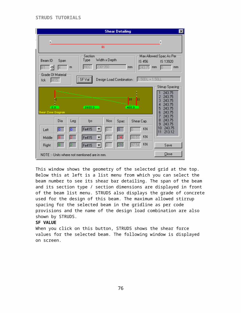
This window shows the geometry of the selected grid at the top. Below this at left is a list menu from which you can select the beam number to see its shear bar detailing. The span of the beam and its section type / section dimensions are displayed in front of the beam list menu. STRUDS also displays the grade of concrete used for the design of this beam. The maximum allowed stirrup spacing for the selected beam in the gridline as per code provisions and the name of the design load combination are also shown by STRUDS. SF VALUEWhen you click on this button, STRUDS shows the shear force values for the selected beam. The following window is displayed on screen.
69
STRUDS TUTORIALS
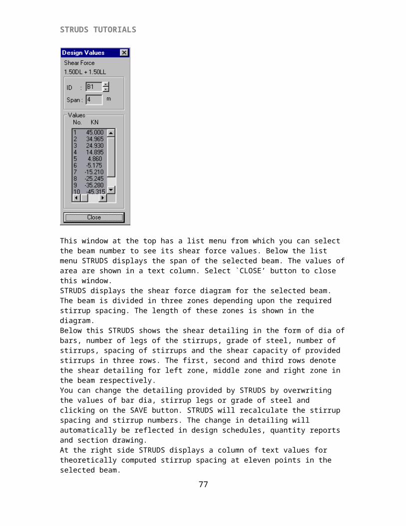
This window at the top has a list menu from which you can select the beam number to see its shear force values. Below the list menu STRUDS displays the span of the selected beam. The values of area are shown in a text column. Select `CLOSE’ button to close this window. STRUDS displays the shear force diagram for the selected beam. The beam is divided in three zones depending upon the required stirrup spacing. The length of these zones is shown in the diagram.Below this STRUDS shows the shear detailing in the form of dia of bars, number of legs of the stirrups, grade of steel, number of stirrups, spacing of stirrups and the shear capacity of provided stirrups in three rows. The first, second and third rows denote the shear detailing for left zone, middle zone and right zone in the beam respectively.You can change the detailing provided by STRUDS by overwriting the values of bar dia, stirrup legs or grade of steel and clicking on the SAVE button. STRUDS will recalculate the stirrup spacing and stirrup numbers. The change in detailing will automatically be reflected in design schedules, quantity reports and section drawing.At the right side STRUDS displays a column of text values for theoretically computed stirrup spacing at eleven points in the selected beam.SAVESelect this button to save the changes, if any, you have made in the detailing. Unless you use this option, your changes will not be reflected in design schedules & quantity reports.CLOSESelect this button to close the window of shear bars detailing.SideBarsThis option allows you to see the detailing for side reinforcement provided in the selected beam. As per IS: 456, sidebars are to be provided in case the depth of beam is more than 750 mm. When you select this option, STRUDS displays following window.
70

STRUDS TUTORIALS
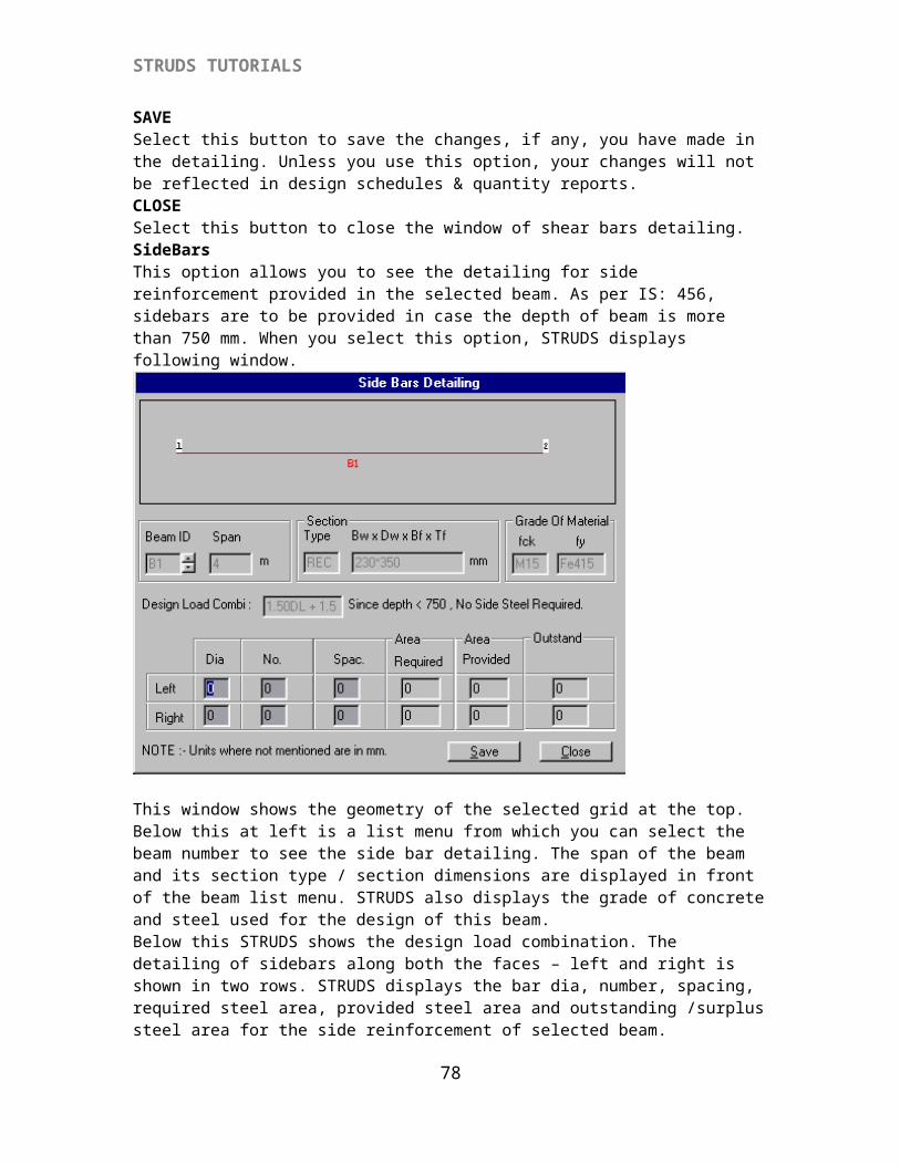
This window shows the geometry of the selected grid at the top. Below this at left is a list menu from which you can select the beam number to see the side bar detailing. The span of the beam and its section type / section dimensions are displayed in front of the beam list menu. STRUDS also displays the grade of concrete and steel used for the design of this beam. Below this STRUDS shows the design load combination. The detailing of sidebars along both the faces – left and right is shown in two rows. STRUDS displays the bar dia, number, spacing, required steel area, provided steel area and outstanding /surplus steel area for the side reinforcement of selected beam.SAVESelect this button to save the changes, if any, you have made in the detailing. Unless you use this option, your changes will not be reflected in design schedules & quantity reports.CLOSESelect this button to close the window of sidebars detailing.
CombinedThis option allows you to see the combined detailing for bottom bars, top bars and stirrups for all the beams in the selected grid. When you select this option, STRUDS displays a window whichShows the geometry of the selected grid at the top with beam labels. Below this a text table is shown describing the detailing. This table shows the beam numbers (Ids), Span of beam (L), Width of beam section (B), Depth of Beam Section (D), bottom steel in the form of dia and number of bars, top steel at left/right/middle and stirrup spacing as per the zones.You can not make any changes in this table. It is displayed for viewing purpose only.Section GraphicsThis option allows you to obtain the graphical representation of the steel detailing and section geometry of all the beams in the selected grid. When you select this option, STRUDS displays following screen.
71
STRUDS TUTORIALS
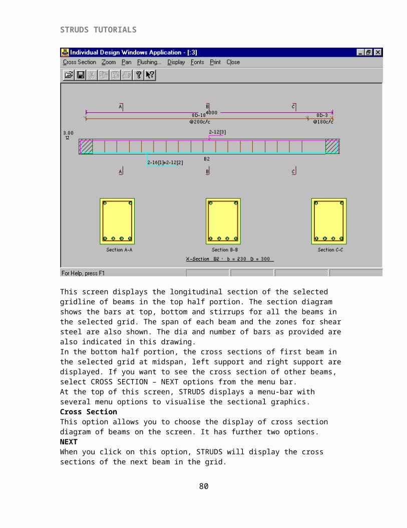
This screen displays the longitudinal section of the selected gridline of beams in the top half portion. The section diagram shows the bars at top, bottom and stirrups for all the beams in the selected grid. The span of each beam and the zones for shear steel are also shown. The dia and number of bars as provided are also indicated in this drawing.In the bottom half portion, the cross sections of first beam in the selected grid at midspan, left support and right support are displayed. If you want to see the cross section of other beams, select CROSS SECTION – NEXT options from the menu bar.At the top of this screen, STRUDS displays a menu-bar with several menu options to visualise the sectional graphics.Cross SectionThis option allows you to choose the display of cross section diagram of beams on the screen. It has further two options.NEXTWhen you click on this option, STRUDS will display the cross sections of the next beam in the grid.PREVIOUSWhen you click on this option, STRUDS will display the cross sections of the previous beam in the grid.ZoomThis option allows you to enlarge the drawings for viewing/printing purpose. It has further three options. Zoom option by default is active in the top half part of screen i.e. for longitudinal section. You can press `Tab’ key from keyboard to make it active in the lower half part of window i.e. for cross section diagram.
72
STRUDS TUTORIALS
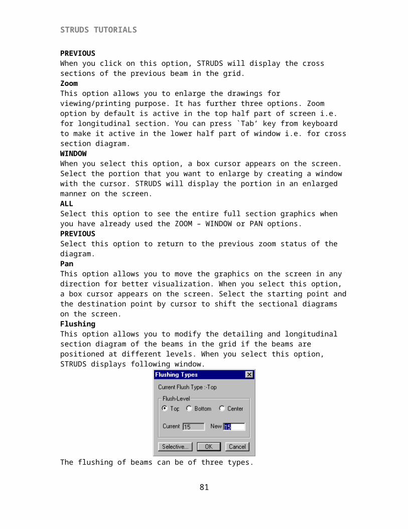
WINDOWWhen you select this option, a box cursor appears on the screen. Select the portion that you want to enlarge by creating a window with the cursor. STRUDS will display the portion in an enlarged manner on the screen.ALLSelect this option to see the entire full section graphics when you have already used the ZOOM – WINDOW or PAN options. PREVIOUSSelect this option to return to the previous zoom status of the diagram. PanThis option allows you to move the graphics on the screen in any direction for better visualization. When you select this option, a box cursor appears on the screen. Select the starting point and the destination point by cursor to shift the sectional diagrams on the screen.FlushingThis option allows you to modify the detailing and longitudinal section diagram of the beams in the grid if the beams are positioned at different levels. When you select this option, STRUDS displays following window.
The flushing of beams can be of three types.TOPThe default flushing while displaying the longitudinal section is TOP. Which means that the top level of all beams in the selected grid is same.BottomIf you select this option the longitudinal section will be displayed in such a manner that the bottom level of beams remains same.
CenterIf you select this option the longitudinal section will be displayed in such a manner that the centre level of beams remains same.
{VIII} INDIVIDUAL COLUMN DESIGN
Design a rectangular column of 3m length carrying an axial load of 76 KN.
Click ‘Design’ option of the control menu of Struds window.Click ‘Standalone design’ option.STRUDS displays a new window i.e. ‘Individual Design Window Application’Click ‘Column’ option.STRUDS displays the window, i.e. ‘Individual Design Window Application’ for column design.
73
STRUDS TUTORIALS
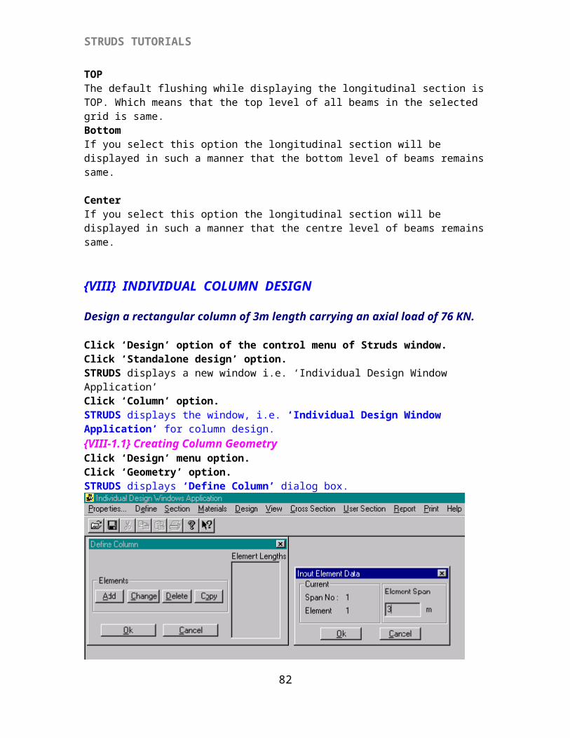
{VIII-1.1} Creating Column GeometryClick ‘Design’ menu option.Click ‘Geometry’ option.STRUDS displays ‘Define Column’ dialog box.
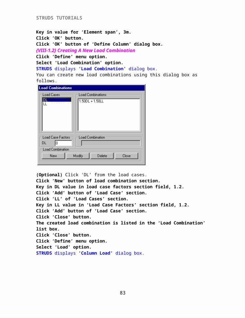
Key in value for ‘Element span’, 3m.Click ‘OK’ button.Click ‘OK’ button of ‘Define Column’ dialog box.{VIII-1.2} Creating A New Load CombinationClick ‘Define’ menu option.Select ‘Load Combination’ option.STRUDS displays ‘Load Combination’ dialog box.You can create new load combinations using this dialog box as follows.
(Optional) Click ‘DL’ from the load cases.Click ‘New’ button of load combination section.Key in DL value in load case factors section field, 1.2.Click ‘Add’ button of ‘Load Case’ section.Click ‘LL’ of ‘Load Cases’ section.Key in LL value in ‘Load Case Factors’ section field, 1.2.
74
STRUDS TUTORIALS
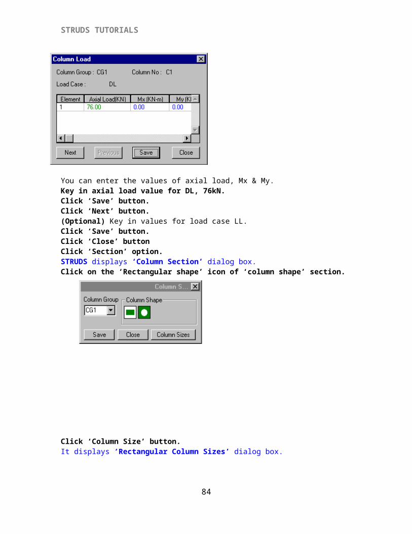
Click ‘Add’ button of ‘Load Case’ section.Click ‘Close’ button.The created load combination is listed in the ‘Load Combination’ list box.Click ‘Close’ button.Click ‘Define’ menu option.Select ‘Load’ option.STRUDS displays ‘Column Load’ dialog box.
You can enter the values of axial load, Mx & My.Key in axial load value for DL, 76kN.Click ‘Save’ button.Click ‘Next’ button.(Optional) Key in values for load case LL.Click ‘Save’ button.Click ‘Close’ buttonClick ‘Section’ option.STRUDS displays ‘Column Section’ dialog box.Click on the ‘Rectangular shape’ icon of ‘column shape’ section.
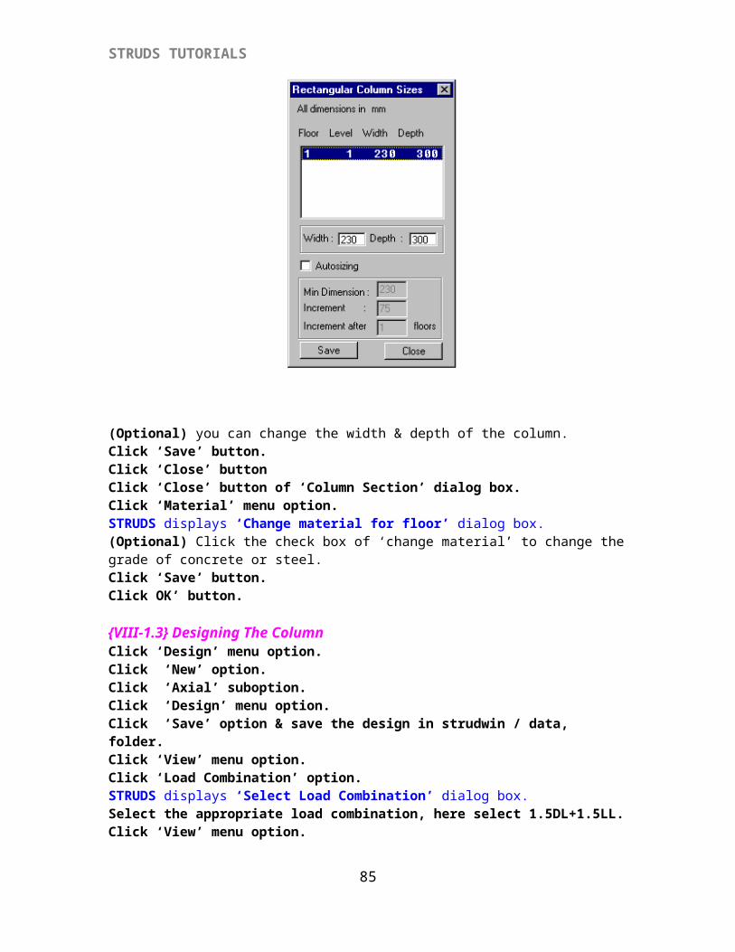
Click ‘Column Size’ button.It displays ‘Rectangular Column Sizes’ dialog box.
75
STRUDS TUTORIALS
(Optional) you can change the width & depth of the column.Click ‘Save’ button.Click ‘Close’ buttonClick ‘Close’ button of ‘Column Section’ dialog box.Click ‘Material’ menu option.STRUDS displays ‘Change material for floor’ dialog box.(Optional) Click the check box of ‘change material’ to change the grade of concrete or steel.Click ‘Save’ button.Click OK’ button.
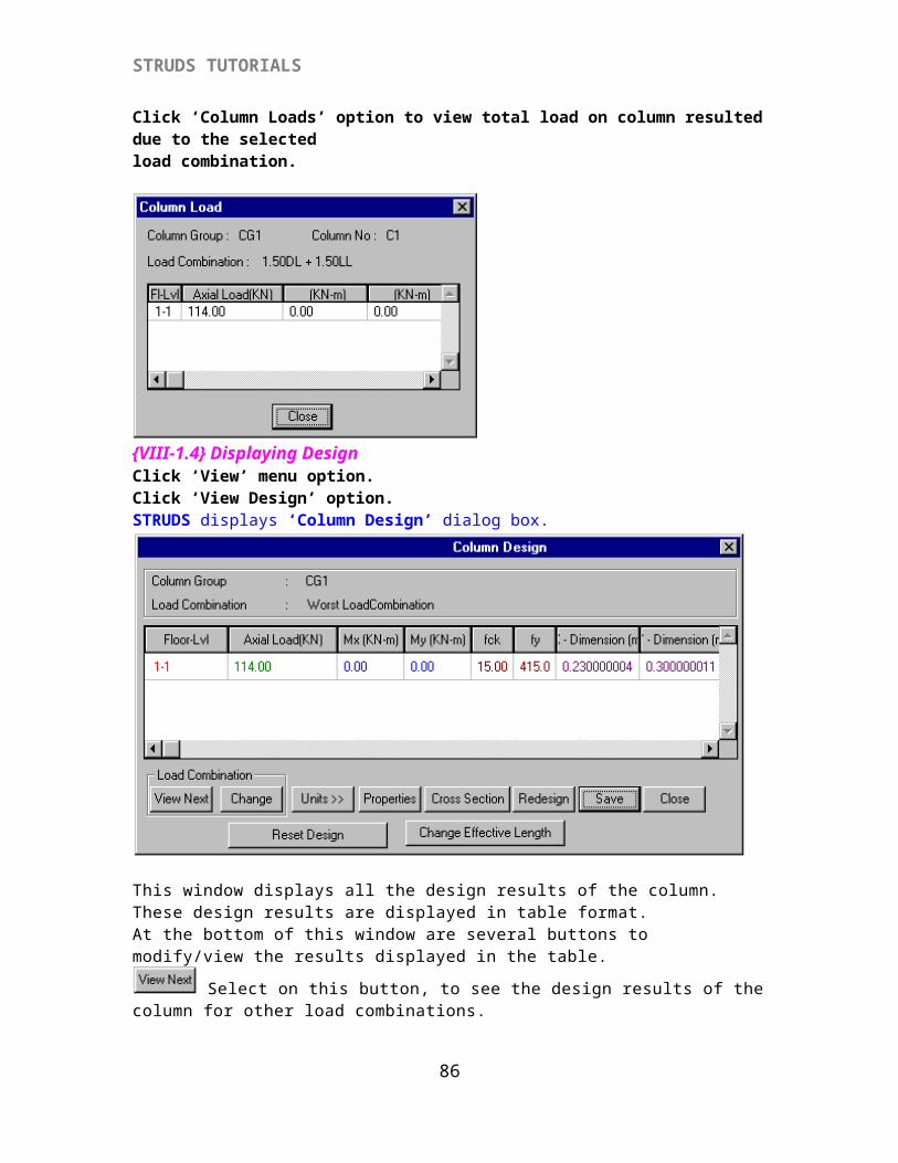
{VIII-1.3} Designing The ColumnClick ‘Design’ menu option.Click ‘New’ option.Click ‘Axial’ suboption.Click ‘Design’ menu option.Click ‘Save’ option & save the design in strudwin / data, folder.Click ‘View’ menu option.Click ‘Load Combination’ option.STRUDS displays ‘Select Load Combination’ dialog box.Select the appropriate load combination, here select 1.5DL+1.5LL.Click ‘View’ menu option.Click ‘Column Loads’ option to view total load on column resulted due to the selected load combination.
76
STRUDS TUTORIALS
{VIII-1.4} Displaying DesignClick ‘View’ menu option.Click ‘View Design’ option.STRUDS displays ‘Column Design’ dialog box.
This window displays all the design results of the column. These design results are displayed in table format. At the bottom of this window are several buttons to modify/view the results displayed in the table.
Select on this button, to see the design results of the column for other load combinations.
This option allows you to change the load combination for design results. STRUDS by default designs all the column for worst load combination. In case you want to specify some other load combination as worst load combination, you can use this option. This
77
STRUDS TUTORIALS
change will be reflected in the design schedules by STRUDS. When you select this option, STRUDS displays following window.
This window displays a drop down menu for the floors in the building. The worst load combination for this floor is also displayed by STRUDS. Select the floor for which youwant to change the load combination for design. Click on the `Select Load Combination>>’ button. This window displays the list of defined load combinations. Select the load combination that you want to apply to the selected column at selected floor. Click on the OK button. STRUDS will then display the design results due to this load combination in the table. You can click on the CANCEL button to close the window without selecting the load combination. This change in table will be reflected in design schedules by STRUDS.
This option allows you to modify the units for the values displayed in the table. When you select this option, STRUDS displays following window.
This window has two drop down menus. The left drop down menus displays the list of items in the table for which you can change the units. The right drop down menu displays the list of unit types available for selected item. Chose the unit you want to apply for the selected item and click on the CLOSE button. STRUDS will change and display the values of the item in the table corresponding to the modified unit.
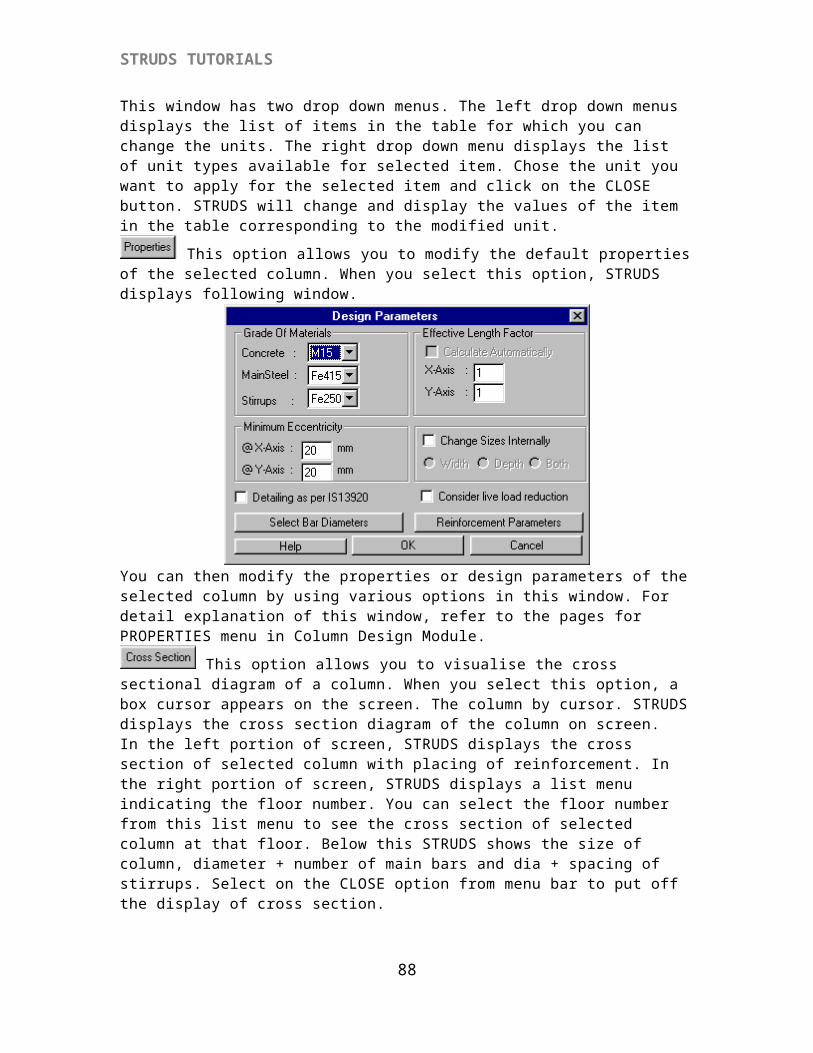
This option allows you to modify the default properties of the selected column. When you select this option, STRUDS displays following window.
78
STRUDS TUTORIALS
You can then modify the properties or design parameters of the selected column by using various options in this window. For detail explanation of this window, refer to the pages for PROPERTIES menu in Column Design Module.
This option allows you to visualise the cross sectional diagram of a column. When you select this option, a box cursor appears on the screen. The column by cursor. STRUDS displays the cross section diagram of the column on screen.In the left portion of screen, STRUDS displays the cross section of selected column with placing of reinforcement. In the right portion of screen, STRUDS displays a list menu indicating the floor number. You can select the floor number from this list menu to see the cross section of selected column at that floor. Below this STRUDS shows the size of column, diameter + number of main bars and dia + spacing of stirrups. Select on the CLOSE option from menu bar to put off the display of cross section.
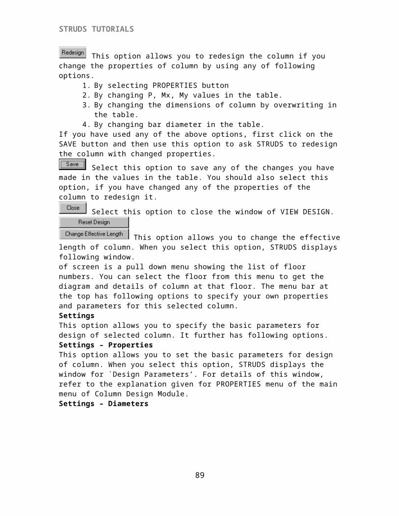
This option allows you to redesign the column if you change the properties of column by using any of following options.
1. By selecting PROPERTIES button2. By changing P, Mx, My values in the table.3. By changing the dimensions of column by overwriting in the table.4. By changing bar diameter in the table.
If you have used any of the above options, first click on the SAVE button and then use this option to ask STRUDS to redesign the column with changed properties.
Select this option to save any of the changes you have made in the values in the table. You should also select this option, if you have changed any of the properties of the column to redesign it.
Select this option to close the window of VIEW DESIGN.
This option allows you to change the effective length of column. When you select this option, STRUDS displays following window.
79
STRUDS TUTORIALS
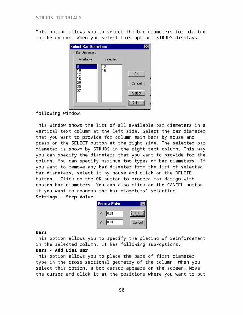
of screen is a pull down menu showing the list of floor numbers. You can select the floor from this menu to get the diagram and details of column at that floor. The menu bar at the top has following options to specify your own properties and parameters for this selected column.SettingsThis option allows you to specify the basic parameters for design of selected column. It further has following options.Settings – PropertiesThis option allows you to set the basic parameters for design of column. When you select this option, STRUDS displays the window for `Design Parameters’. For details of this window, refer to the explanation given for PROPERTIES menu of the main menu of Column Design Module.Settings – DiametersThis option allows you to select the bar diameters for placing in the column. When you select this option, STRUDS displays following window.
This window shows the list of all available bar diameters in a vertical text column at the left side. Select the bar diameter that you want to provide for column main bars by mouse and press on the SELECT button at the right side. The selected bar diameter is shown by STRUDS in the right text column. This way you can specify the diameters that you want to provide for the column. You can specify maximum two types of bar diameters. If you want to remove any bar diameter from the list of selected bar diameters, select it by mouse and click on the DELETE button. Click on the OK button to proceed for design with chosen bar diameters. You can also click on the CANCEL button if you want to abandon the bar diameters’ selection.Settings - Step Value
80
STRUDS TUTORIALS
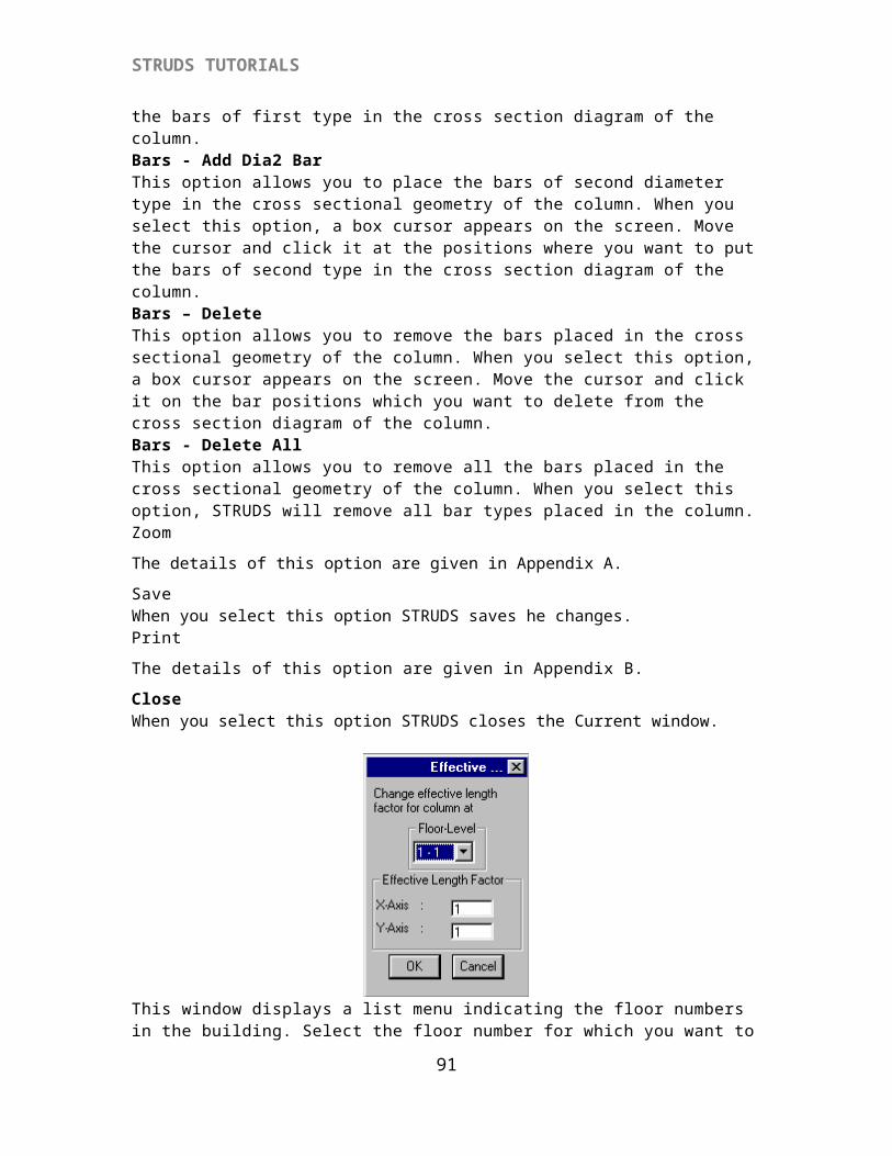
BarsThis option allows you to specify the placing of reinforcement in the selected column. It has following sub-options.Bars - Add Dia1 BarThis option allows you to place the bars of first diameter type in the cross sectional geometry of the column. When you select this option, a box cursor appears on the screen. Move the cursor and click it at the positions where you want to put the bars of first type in the cross section diagram of the column.Bars - Add Dia2 BarThis option allows you to place the bars of second diameter type in the cross sectional geometry of the column. When you select this option, a box cursor appears on the screen. Move the cursor and click it at the positions where you want to put the bars of second type in the cross section diagram of the column.Bars – DeleteThis option allows you to remove the bars placed in the cross sectional geometry of the column. When you select this option, a box cursor appears on the screen. Move the cursor and click it on the bar positions which you want to delete from the cross section diagram of the column.Bars - Delete AllThis option allows you to remove all the bars placed in the cross sectional geometry of the column. When you select this option, STRUDS will remove all bar types placed in the column.Zoom
The details of this option are given in Appendix A.
SaveWhen you select this option STRUDS saves he changes.Print
The details of this option are given in Appendix B.
CloseWhen you select this option STRUDS closes the Current window.
81
STRUDS TUTORIALS
This window displays a list menu indicating the floor numbers in the building. Select the floor number for which you want to modify the effective length of the selected column. Below this are two fields indicating the factor for effective length about X and Y-axis for the column. By default the factors for effective length are 1 for both axes. However you can modify this by specifying the factor by overwriting the default values in the fields.
{IX} FOOTING DESIGN
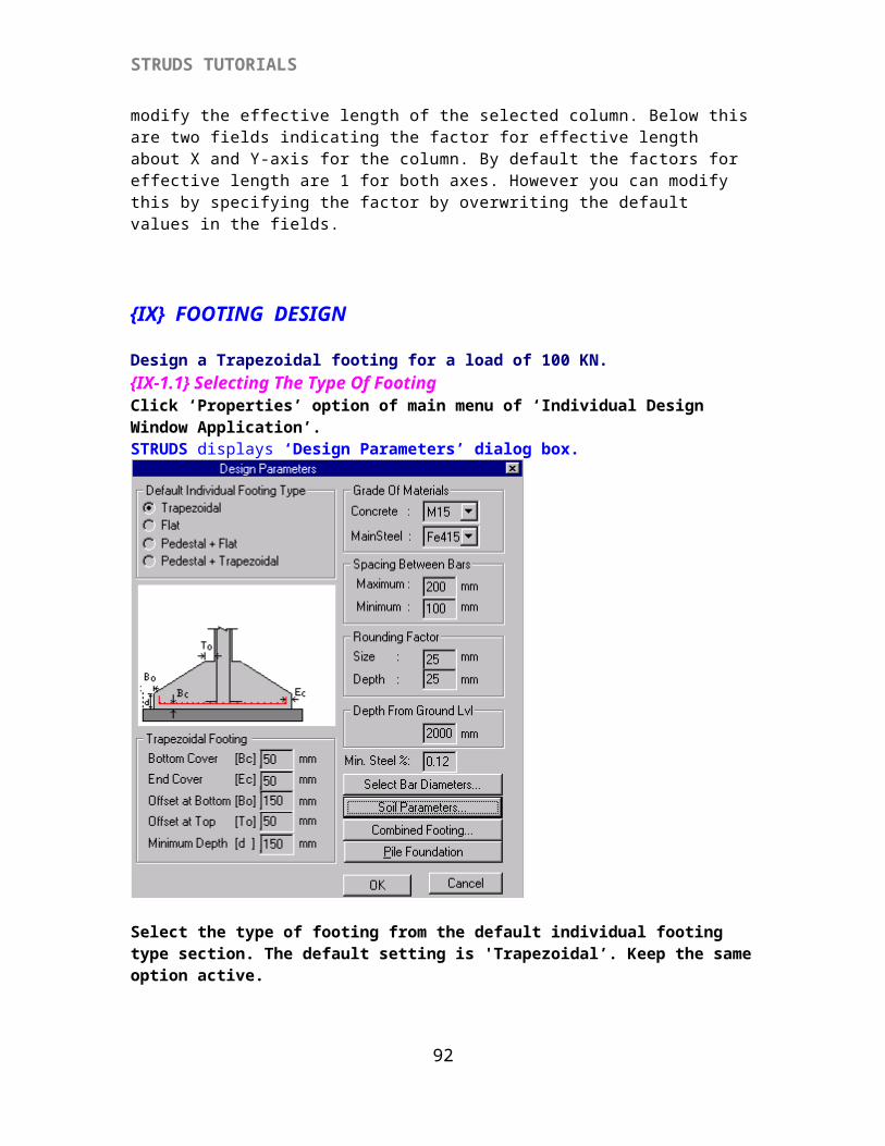
Design a Trapezoidal footing for a load of 100 KN.{IX-1.1} Selecting The Type Of FootingClick ‘Properties’ option of main menu of ‘Individual Design Window Application’.STRUDS displays ‘Design Parameters’ dialog box.
82
STRUDS TUTORIALS
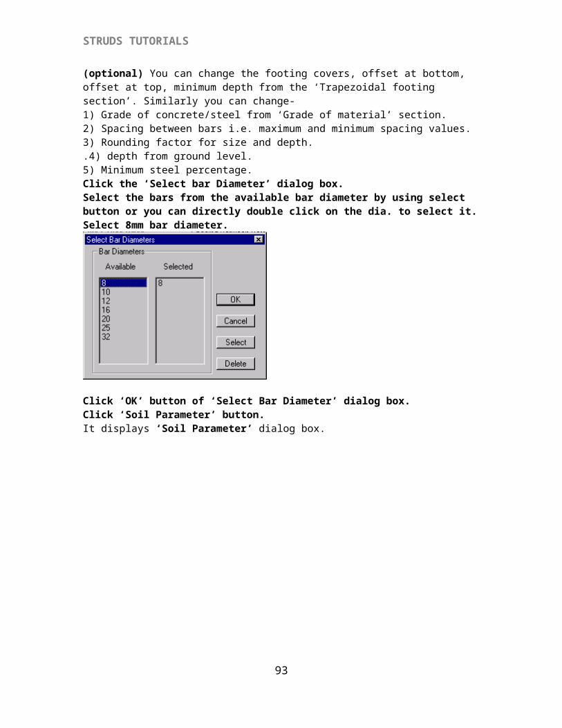
Select the type of footing from the default individual footing type section. The default setting is 'Trapezoidal’. Keep the same option active.(optional) You can change the footing covers, offset at bottom, offset at top, minimum depth from the ‘Trapezoidal footing section’. Similarly you can change-1) Grade of concrete/steel from ‘Grade of material’ section.2) Spacing between bars i.e. maximum and minimum spacing values.3) Rounding factor for size and depth..4) depth from ground level.5) Minimum steel percentage.Click the ‘Select bar Diameter’ dialog box. Select the bars from the available bar diameter by using select button or you can directly double click on the dia. to select it. Select 8mm bar diameter.
83
STRUDS TUTORIALS
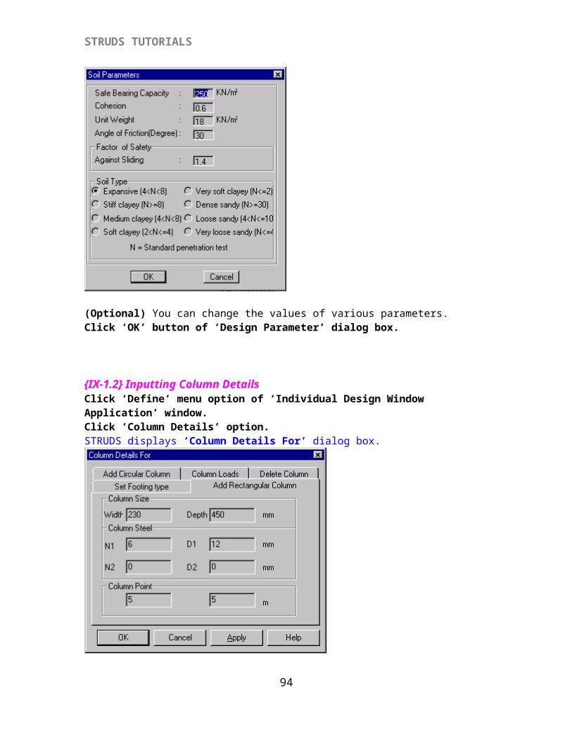
Click ‘OK’ button of ‘Select Bar Diameter’ dialog box.Click ‘Soil Parameter’ button.It displays ‘Soil Parameter’ dialog box.
(Optional) You can change the values of various parameters.Click ‘OK’ button of ‘Design Parameter’ dialog box.
{IX-1.2} Inputting Column DetailsClick ‘Define’ menu option of ‘Individual Design Window Application’ window.Click ‘Column Details’ option.STRUDS displays ‘Column Details For’ dialog box.
84
STRUDS TUTORIALS
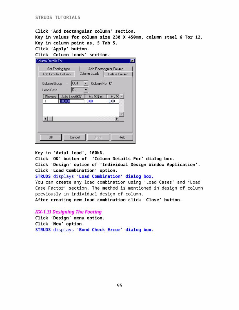
Click ‘Add rectangular column’ section.Key in values for column size 230 X 450mm, column steel 6 Tor 12.Key in column point as, 5 Tab 5.Click ‘Apply’ button.Click ‘Column Loads’ section.
Key in ‘Axial load’, 100kN.Click ‘OK’ button of ‘Column Details For’ dialog box.Click ‘Design’ option of ‘Individual Design Window Application’.Click ‘Load Combination’ option.STRUDS displays ‘Load Combination’ dialog box.You can create any load combination using ‘Load Cases’ and ‘Load Case Factor’ section. The method is mentioned in design of column previously in individual design of column.After creating new load combination click ‘Close’ button.
85
STRUDS TUTORIALS
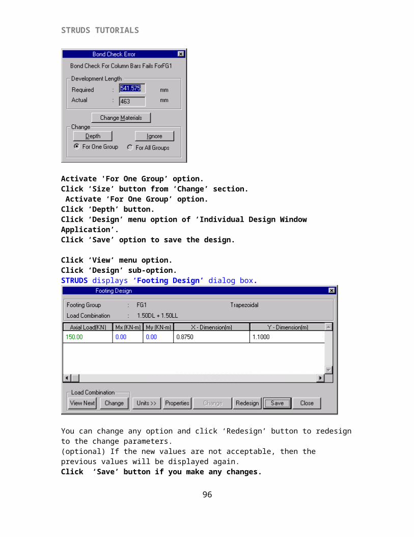
{IX-1.3} Designing The FootingClick ‘Design’ menu option.Click ‘New’ option.STRUDS displays ‘Bond Check Error’ dialog box.
Activate 'For One Group’ option.Click ‘Size’ button from ‘Change’ section. Activate ‘For One Group’ option.Click ‘Depth’ button.Click ‘Design’ menu option of ‘Individual Design Window Application’.Click ‘Save’ option to save the design.
Click ‘View’ menu option.Click ‘Design’ sub-option.STRUDS displays ‘Footing Design’ dialog box.
You can change any option and click ‘Redesign’ button to redesign to the change parameters.(optional) If the new values are not acceptable, then the previous values will be displayed again.Click ‘Save’ button if you make any changes.
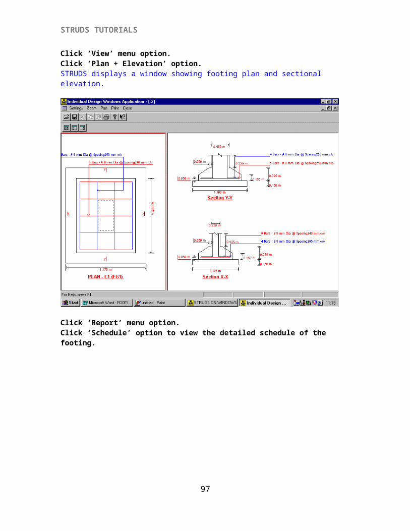
Click ‘View’ menu option.Click ‘Plan + Elevation’ option.
86

STRUDS TUTORIALS
STRUDS displays a window showing footing plan and sectional elevation.
Click ‘Report’ menu option.Click ‘Schedule’ option to view the detailed schedule of the footing.
87
STRUDS TUTORIALS
It displays the new window ‘Individual Design Window Application (: 2).Click ‘Quantity’ option to view the quantity of steel and concrete.Click ‘Close’ option.Click ‘Detail Report’ option to view the detailed report of design of the footing.
88
STRUDS TUTORIALS
SAMPLE BUILDING
DESIGN
89
STRUDS TUTORIALS
90
STRUDS TUTORIALS
91
STRUDS TUTORIALS
92
STRUDS TUTORIALS
93
STRUDS TUTORIALS
94
STRUDS TUTORIALS
95
STRUDS TUTORIALS
{X} SAMPLE BUILDING DESIGN
{X-1} PREPROCESSOR
Click the `Preprocessor' option from menu bar at the top of Main Menu.
STRUDS displays the sub-menu of Preprocessor.
{X-1.1} Drawing Floor Plan
{X-1.1a} Defining Floors By using different options in this menu you will be able to generate the model for the Building Project in 2d or 3d form with graphical input.
Click the `Building' option from the menu.Click the `New' option.
96
STRUDS TUTORIALS
STRUDS displays a dialog box and asks you to enter the project information such as name, location etc. You can fill up the relevant information in the fields available. If you do not want to write any information, just click the `OK' button from the dialog box.
Click the ‘FloorPlan’ option from the menu bar.Click the ‘Skeleton’ option from the drop down menu.STRUDS displays ‘Define no of floors’ dialog box.
Type 5 in the field in front of Define no of floors.Click ‘OK’ button.STRUDS displays ‘Skeleton’ dialog box.
Select floor no 1 from the drop down list of Floor No. ------------------( plinth / ground floor)By default Height of floor is 3m and the Level of floor is also3m. Click ‘Save’ button.The entered data gets saved and listed in the list box.Select floor no 2 from the drop down list of Floor No. ------------------( 1st floor)The level of floor changes automatically to 6.0 m according to the floor no. Click ‘Save’ button.Select floor no 3 from the drop down list of Floor No. ------------------( 2nd floor)Click ‘Save’ button.Select floor no 4 from the drop down list of Floor No. ------------------( 3rd floor)
97
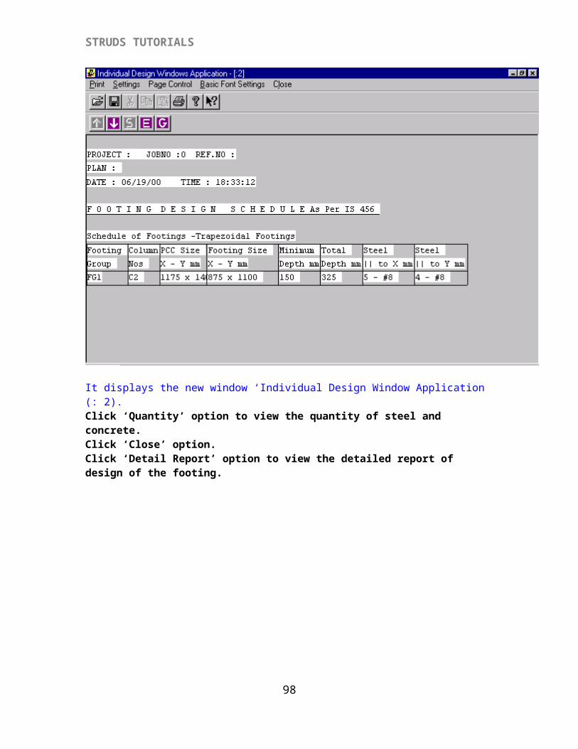
STRUDS TUTORIALS
Click ‘Save’ button.Select floor no 5 from the drop down list of Floor No. ------------------( 4th floor)
Click ‘Save’ button.You can change any data entry for any floor for that select the particular floor then change the values and click ‘Update’ button.Click ‘OK’ button.
Click the ‘FloorPlan’ option from the menu.Click the ‘Set’ option.STRUDS displays ‘Select Floor ID’ dialog box.
Click the drop down arrow and select ‘1’.This means we are now setting the floor1 active to create the drawing.Click ‘OK’ button.
{X-1.1b} Creating Slabs PanelsSTRUDS displays a screen with a menu bar at top having a number of Menu options for Graphics generation.Now you are working with the Graphical Data Generation module of STRUDS.
In STRUDS the input is done by using 2d plane grid method. You are required to draw the floor plans of the building by defining slab panels.
Click the `Create' option from the menu bar.Click the `Slab' option from the drop down menu menu.Click the `Rectangular' option from the second drop down menu.
A box cursor with hair lines is displayed on screen. You can move this cursor by using mouse or Up, Down, Left and Right arrow keys from the key board. At the bottom of the screen, STRUDS displays the command to be given by the user.
STRUDS displays command`Enter First Point of Slab' : Type 3 3 and press Enter Key.`Enter Dimension / Click Second Point of slab' : Type 4 5 press enter.
98
STRUDS TUTORIALS
You have given the starting point of slab at X co-ordinate 3.0 meters and Y co-ordinate 3.0 meters from the bottom left corner of the screen. The slab dimensions given are X length 4 meters and Y length 5 meters.
STRUDS now displays a dialog box in which you can specify the properties and loading on this slab.
Click icon from the dialog box.By clicking this option you allow the program to decide upon the one way or two way spanning of slab by calculating the aspect ratio.
Change the thickness of slab from 100 mm to 120 mm by overwriting in the field denoting `Thickness'.Click `OK' button from the dialog box.
The slab panel is displayed on the screen. Press F7 key from the key board. This key is the shortcut to redraw the graphics on the screen. By pressing the key the node numbers, element numbers and slab numbers become visible on screen. To put on / off these numbers you can use F4, F5 and F6 keys.
You are still in the slab create mode. You will remain in this mode till you press Esc key or click some other option from the menu.
STRUDS again displays following command
`Enter First Point of the Slab': Press F2 key from the key board (or press the right button of the mouse.)This key is the shortcut to define a point with respect to a node. STRUDS displays a small menu list.
99

STRUDS TUTORIALS
Click the ‘Node’ option from this list.STRUDS displays following command
`Enter Node ID / Select a Node:’Click the box cursor along the element no. 2 and near the node no. 2. This way the node no. 2 will be selected as the first point of the slab.
STRUDS displays command`Enter Dimension / Click second point of Slab' :Type 2.5 6 and press enter key.
Again the dialog box inquiring properties of slabs is displayed on the screen.
Change the thickness of slab from 120mm to 100mm in the field provided for thickness.Here you may note that once you change the value in any of the field, that value is taken as default value while defining the next slab panel.
Click the icon for automatic decision for one way or two way spanning of the slab.Click the `OK' button from the dialog box.The second slab panel is displayed on the screen.
Press the F2 key from keyboard.STRUDS again displays the window list for Object Snap mode.
Click the `Node' option from this list.STRUDS displays command`Enter Node ID / Select a Node' :
Select the node no. 4 by moving the box cursor on it and clicking the left button of mouse.STRUDS displays command`Enter Dimension / Click second point of the slab' :
Type 4 3.5 and press enter key.Again the dialog box inquiring slab properties is displayed.
Click icon.Click `OK' button.The third slab panel is displayed on screen.
100
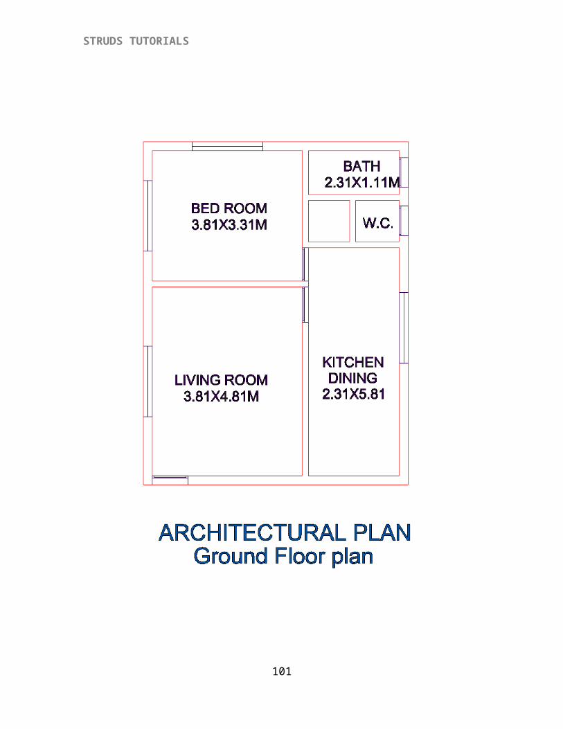
STRUDS TUTORIALS
Press F2 key.Select `Node' option.Select node no. 7 by using mouse.STRUDS displays command`Enter Dimension / Select second point of slab' :Type 1.2 1.2 press enter key.
Click icon for slab denoting slab spanning one way vertically.Click `OK' button from the dialog box.
The fourth slab panel is displayed on screen.
Press F5 key to put off the element numbers.Press F2 key.Select `Node' option.Select node no 6 by mouse.Press F2 keySelect `Node' option.Select node no. 11 by mouse.
Click icon from the dialog box.Click 'Sunk Depth' box from the Sunk Slab option and enter ' 0.51'Click ' Material Density ' box from the Sunk Slab option and enter ' 20'
Click `OK' button.Fifth slab panel is displayed on screen.
101
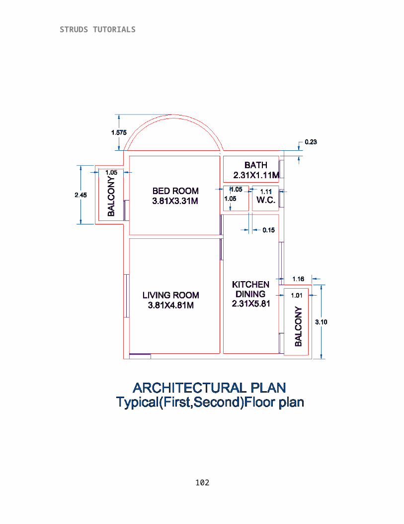
STRUDS TUTORIALS
Press F2 key.Select `Node' option.Select node no. 8 by mouse.Press F2 keySelect `Node' option.Select node no. 13 by cursor.
Click option from slab properties dialog box.Click 'Sunk Depth' box from the Sunk Slab option and enter ' 0.23Click ' Material Density ' box from the Sunk Slab option and enter ' 20'
Click `OK' option.The sixth slab panel is displayed on the screen.
Press F2 key.Select `Offset' option.STRUDS displays command`Enter Node Id / Select a node' :Type 4 and press Enter key.STRUDS displays command`Enter X offset': Type 0 press enter.`Enter Y offset': Type 0.6 press enter.`Enter Z offset': Type 0 press enter.
STRUDS displays command`Enter Dimension / Click second point of Slab':Type -1.2 2.3 and press enter key.
102
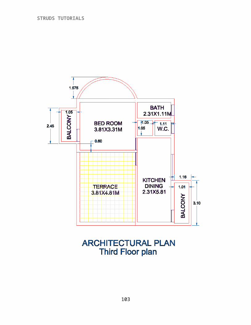
STRUDS TUTORIALS
Select the icon displaying which is for cantilever slab the load of which is transferred on right side beam.Click `OK' button from the dialog box.The seventh slab is displayed on the screen.
Press F2 keySelect `Node' option.Select node no. 5 by cursor.STRUDS displays command`Enter Dimension / Click second point of slab':
Type 1.2 2.8 press enter key.
Select icon for slab spanning one way in horizontal direction.Click `OK' button from the dialog box.The eighth slab panel is displayed on the screen.
This way you have generated all the eight slab panels of the floor plan.
{X-1.1c} Drawing Curved Element
To draw the curved portion slab portion, Select `Create' from menu bar.Click `Curved Element' from the pull down menu.Click `Three Point' from the second pull down menu.
`Enter First point of Curve':Press F2 key.Select `Node' option.Select node number 8 by cursor.
`Enter Second Point of Curve':Press F2 key.Select `Offset' option.
`Enter Node ID / Select Node': Type 8 press enter key`Enter X offset': Type -2.0 press enter`Enter Y offset': Type 1.5 press enter`Enter Z offset': Type 0 press enter`Enter Third Point of curve':Press F2 KeySelect `Node' option from menuSelect node no. 9 by cursorThe curved beam is displayed on the screen.
Please note that this is a curved beam and not a circular slab. If you need to have a circular slab, the same can be defined by drawing a curved beam and providing the slab load on this beam as UDL. Also the point to be noted while drawing a curved element is to select the three points (Start, mid and end) in anti clockwise manner.
103
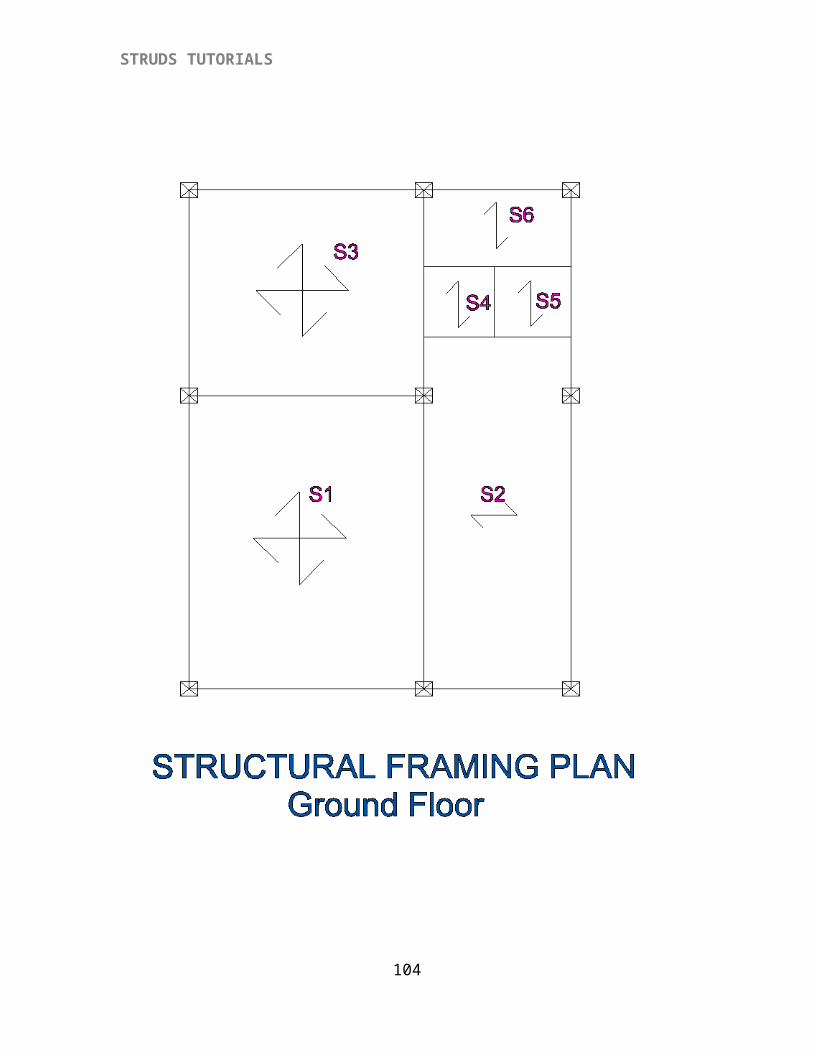
STRUDS TUTORIALS
{X-1.2} Locating Column Positions
After drawing the floor plan, the next stage is to locate positions of columns. The columns can be located on nodes or anywhere along the elements.
Select `Create' option from menu bar.Select `Column' from pull down menu.Select `Auto Add' option from the second level pull down menu.By using this option the blinking cursor automatically goes at every node and a message is displayed`Mark column at this node'
Also available is a list of icons which you can click by mouse. Or you can press Y N L R U D O S letters from the keyboard to specify your selection.
Y - means locate column at this nodeN - means do not locate column at this nodeL - means locate column to the left of this nodeR - means locate column to the right of this nodeU - means locate column to the upside of this nodeD - means locate column to the downside of this nodeO - means locate column away from nodeS - means to stop locating the columns
Cursor first starts blinking at node no. 1Press Y keyCursor blinks at node no. 2Press YCursor blinks at node no. 5Press YCursor blinks at node no 19Press NCursor blinks at node no. 21Press NCursor blinks at node no. 20Press NCursor blinks at node no. 4Press YCursor blinks at node no. 3Press YCursor blinks at node no. 15Press NCursor blinks at node no. 16Press NCursor blinks at node no. 7
104
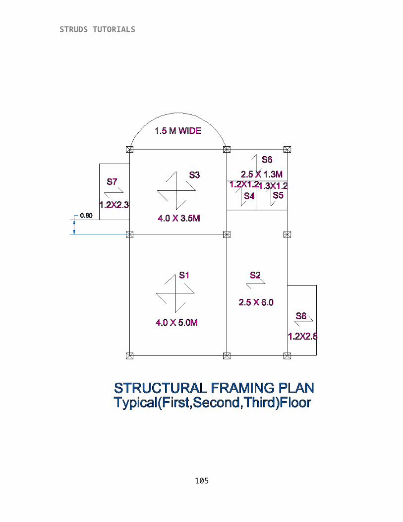
STRUDS TUTORIALS
Press NCursor blinks at node no. 10Press NCursor blinks at node no. 6Press NCursor blinks at node no. 12Press NCursor blinks at node no. 11Press NCursor blinks at node no. 13Press NCursor blinks at node no. 18Press NCursor blinks at node no. 17Press NCursor blinks at node no. 9Press YCursor blinks at node no. 8Press yCursor blinks at node no. 14Press YCursor then blinks at nodes 22 to 28 along the curved element.Press N at all these nodes.
This way you have located columns by using `Auto Add' option.Now if you want to locate column away from node.
Select `Create' from menu barSelect `Column'Select `Locate'
STRUDS displays message`Enter a point for Column':The box cursor appears on the screen.
Press F2 keySelect `Offset' option
`Enter Node ID / Select Node':Type 6 press enter`Enter X offset': Type 0 press enter`Enter Y offset': Type -1.0 press enter`Enter Z offset' : Type 0 press enter.
The column is located 0.6 meter down to node no. 6.This way you have located all the columns. This is nothing but specifying the boundary conditions at nodes. When a column is located, it means that the vertical displacement (in Z axis) at the specified node is zero.
{X-1.3} Specifying Boundary Conditions
105
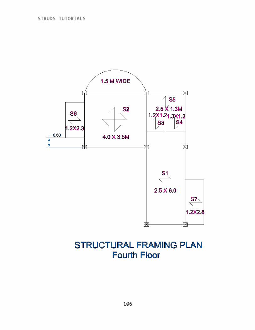
STRUDS TUTORIALS
Now from the observation of the floor plan you can see that at nodes 16, 17 and 21 the cantilever beams are projecting from main beams. The boundary condition at these nodes is by default taken as a simple support. To provide fixity at these nodes, you should follow following steps.
Click `Support' option from menu bar.STRUDS displays the screen showing the floor plan and right hand side menu items vertically arranged.
Presently the boundary group defined is BG1 only which denotes columns at (W - zero)the specified nodes. You can specify any type of boundary group and attach it to the required node.From the floor plan geometry it can be seen that at nodes 16 17 and 21, we need to provide fixity about Y axis i.e. rotation about Y axis is restrained (Ry = 0).
Click the option `Define Group'. STRUDS displays a window with different fields to click to define a group. You are defining group no. 2 for nodes 16, 17 and 21.
Click the box of `Y - Rotation'.Click `OK' button.Select the boundary group BG2 by clicking on the drop down arrow button for the Boundary Group title. Click the `Add Node' button from the menu.A box type cursor appears on the screen.
106
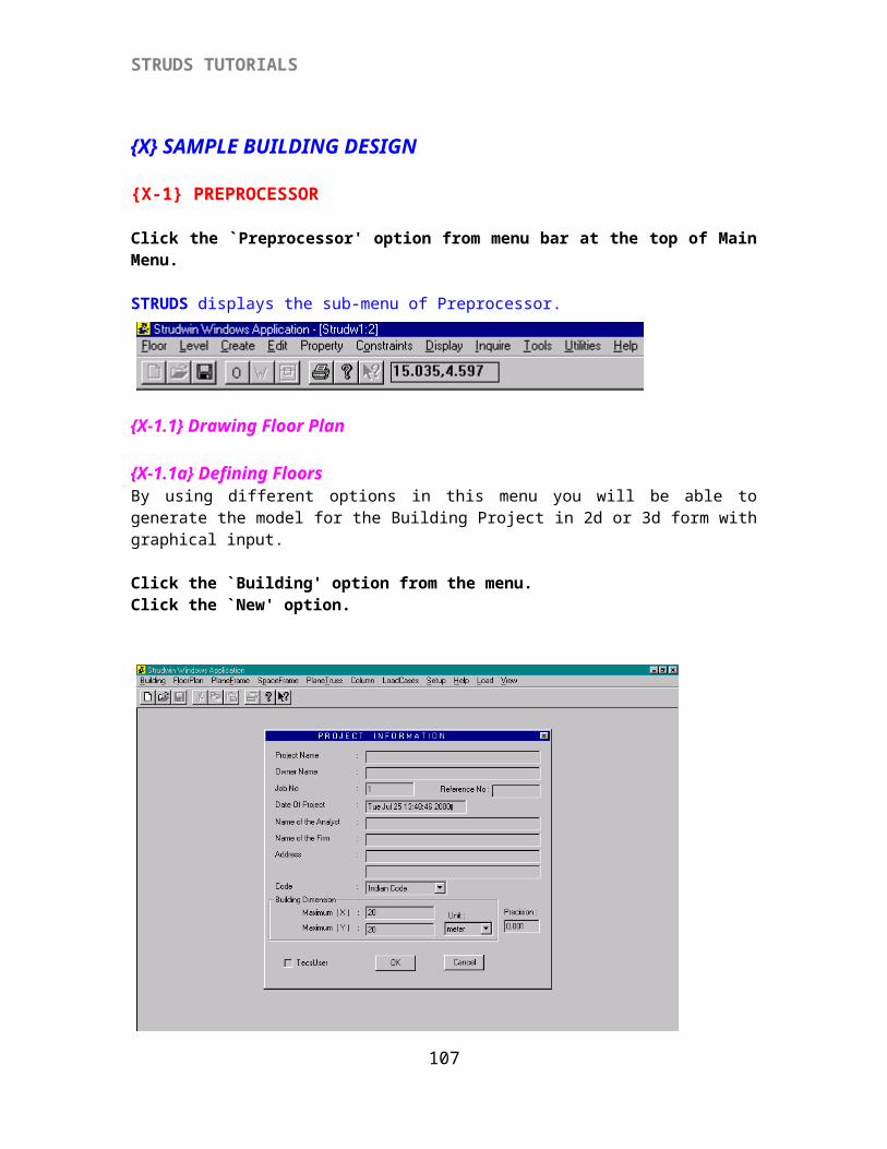
STRUDS TUTORIALS
Select node 16, 17 and 21 by mouse.
Click ‘Close’ button by mouse.
Now you have drawn the floor plan, located the columns and specified the support conditions wherever required.
{X-1.4} Creating And Attaching Sections to Beams
The next step is to provide the sections to the beams.
Select ‘Property’ from menu bar.Point to ‘Create’. Point to ‘Section’ and click the mouse.A Window appears on the screen, which has a number of fields and buttons.
107
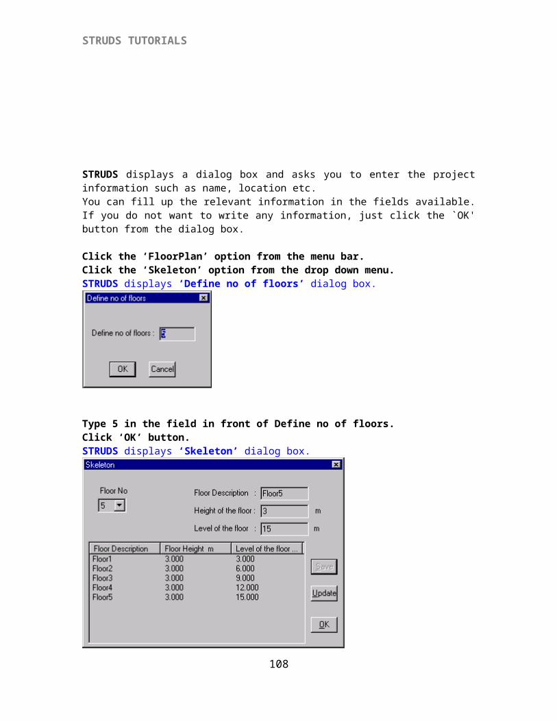
STRUDS TUTORIALS
Click ‘New’ by mouse or pressing ‘Alt+N’ from Keyboard.Click the dropdown icon at the ‘Section Types’ pull down menu.Select ‘Rectangular’.
STRUDS displays two fields for width and depth of the ‘Sec1’.
Type ‘230’ in the field in front of b.Press ‘Tab’ key from keyboard or click mouse in the next field.Type ‘450’ in the field.Select ‘Save’ buttonSelect ‘New’
Again select ‘Rectangular’ from the pull down menu.Type ‘150’ in the field of bType ‘380’ in the next fieldSelect ‘Save’
Click ‘New’ ButtonSelect ‘Rectangular’Type ‘230’ in the field of b and 100 in the field of d. Select ‘save’.Select ‘close’ button.
This way you have defined three rectangular sections Sec1, Sec2 and Sec3 which you can provide to any of the beams in the floor plan. Please note that Sec3 is a hidden beam section or dummy beam. Since it is imperative that every element must have a section for the analysis to be performed. So some times we need to provide a nominal section to an element where a beam is not required. For example, a cantilever slab is defined by four surrounding elements. The load of the slab is transferred on one of the element which acts as a beam. The other three elements do
108
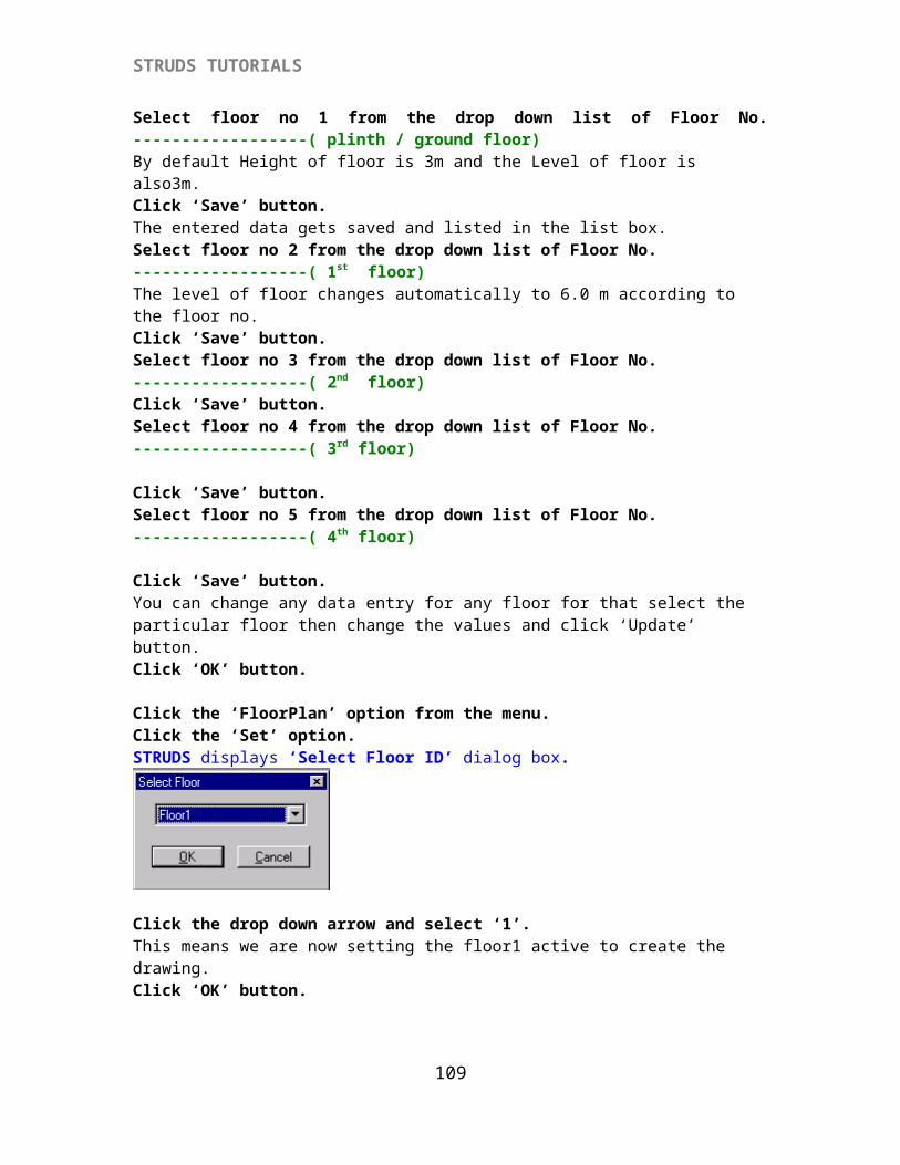
STRUDS TUTORIALS
not act as a beam. In such case we need to provide a hidden beam or dummy beam section at such elements.
Select ‘Property’ from menu bar.Point to ‘Attach’Point to ‘Section’ and click mouse.
A small window appears on the screen with a pull down menu and menu buttons to allow you to attach the defined sections to the beams.
Select ‘Sec3’ from the pull down menu.Select ‘Locate’ buttonA box type cursor appears on the screen.
Select element numbers 21,23 and 24 by clicking the cursor along these elements.Select ‘Sec1’ from pull down menu.Click ‘Grid’ button.
Again the box type cursor appears on the screen.When you use the option ‘Grid’ and click it along any element, that element and all other elements in line with this element will have the chosen section attached.
Select element No. 4,10,27 & 1 by clicking the mouse along these elements.Select ‘Sec2’ from the pull down menu.Click ‘Rest’ button.All the remaining elements, which do not have any section, are attached with sec2 by this process.
Select ‘Close’ button.
109
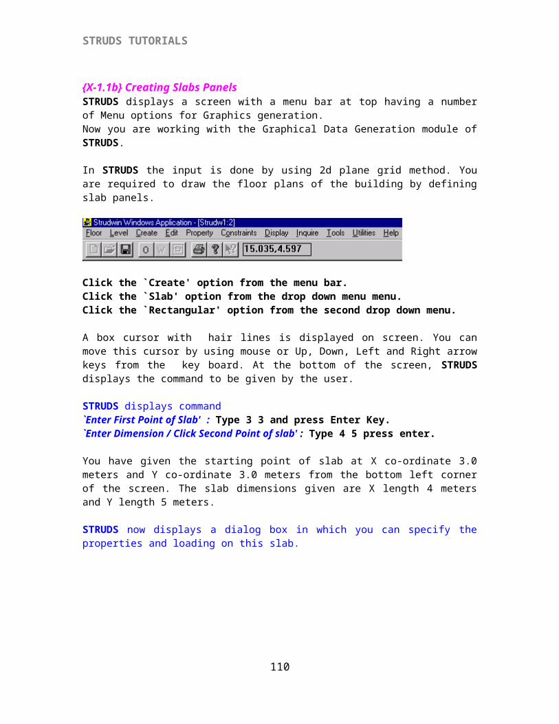
STRUDS TUTORIALS
All the remaining elements, which do not have any section, are attached with Sec2 by this process.
Select ‘close’ button.This way you have specified the section sizes for all the elements in the floor plan. It should be noted that you must have specified the section for all the elements in the floor plan before proceeding to analysis.
{X-1.5} Creating and Attaching Walls
In STRUDS you can attach the walls on beams as per your requirement. STRUDS will automatically calculate the weight of walls on beams as UDL as per the physical attributes provided by you. Now to generate walls follow following procedure
Select ‘Create’ from menu bar.Select ‘wall’ from the menu.A window with fields and buttons appears on the screen.
Click ‘New’ button.In the field for ‘Name’ type W1In the field for thickness type 0.23In the field for height type 3From the pull down menu select ‘BRK’.
‘BRK’ stands for brick masonry. The density of brick masonry 19 kn/m3 is automatically taken by the program. If you want to change the density, you can simply click in the field and overwrite new value of density.
Select ‘Define’ button from the window.Select ‘New’ button.
In the field of Name type (w2).In the field of thickness type ‘100’Select ‘Define’ button from the window.
Select ‘Define’ button from the window.
110
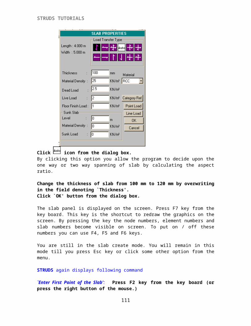
STRUDS TUTORIALS
Select ‘New’ button.
In the field of Name type (w3).In the field of thickness type ‘100’In the field for height type 1.0 M
Select ‘Define’ button from the window.
This way you have defined three walls W1,W2 &W3 of brick masonry and thickness 230 mm,100mm and 100 mm respectively.
Click ‘Close’.Select ‘Property’ from menu bar.Select ‘Attach’Select ‘Wall’ and click the mouse.
A small window appears on the screen. You can use the various options in this window to attach the defined walls to the elements in the floor plan.
The flag for Consider Element section is always true by default i.e. while attaching a wall to an element, the program will automatically, deduct the depth of the beam from the wall height while calculating the wall load on that element. If you do not want to deduct the depth of beam section from wall height, you can do so by clicking the box of consider element section.
Select ‘W1’ from the pull down menu.Select ‘Grid’ button from the window.Select elements 1,4,10 and 27 by clicking the box type cursor along these elements.Select ‘W2’ from the pull down menu.Select ‘Grid’ button from the window.Select element numbers 2,3,7,15 and 13 by clicking the box type cursor along these elements.
All the elements in line of these elements are attached with wall W2.
Select ‘W3’ from the pull down menu.Select ‘Grid’ button from the window.
111
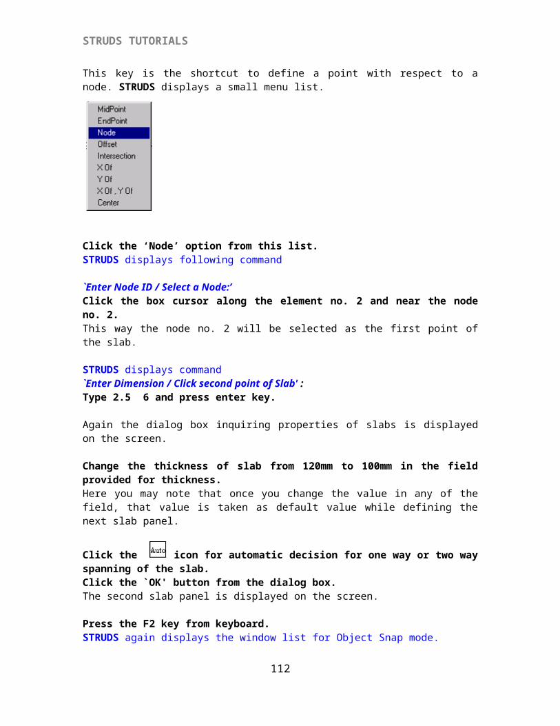
STRUDS TUTORIALS
Select element numbers 26, 28,21,24 and 23 by clicking the box type cursor along these elements.Select ‘Curve’ button from the window.Select the curved element by clicking the box type cursor along it.Select ‘Close’ button from the window.
Select ‘Display’ from menu bar.Select ‘Entities’. A window is displayed on the screen with several fields and small boxes to On/Off the flag. You can put On/Off the display of any of the entities listed in this dialog box by clicking the small box before these entities.
112
STRUDS TUTORIALS
Select the box for ‘Wall’ by clicking mouse Select ‘OK’ button.The program on screen displays the walls attached to corresponding elements.
Select ‘Floor’ from menu bar.Select ‘Generate Wall Loads’ from the drop-down menu.Once you use this option, STRUDS automatically calculates the wall load on corresponding elements.STRUDS displays a message ‘Wall load generation is completed’Click ‘OK’
{X-1.6} Creating and Attaching External Loads
In case you want to provide any extra load on the elements; for example, in this plan the circular slab is defined by a curved beam. There physically is no slab enclosed by this curved beam. Here as we want to attach the load of the slab on curved beam, we can do the same by following procedure.
Select ‘Property’ from menu bar.Select ‘Create’.Select ‘Load’.Select ‘Elemental Loads’ & click the mouse.
A Window appears on the screen with a pull down menu and few buttons.
113
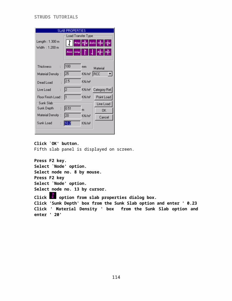
STRUDS TUTORIALS
Select ‘New’ buttonSelect ‘Full UDL’ from the pull down menu Type 3 in the field in front of W : (which denotes the value of uniformly distributed load on the elements.) Click ‘save’ button.Select ‘Close’ button.
Select ‘Property’.Select ‘Attach’.Select ‘Loads’.Select ‘G1’ from the pull down menuSelect ‘curve’ button from the window.Select the curved element by taking box cursor anywhere along the curved element and clicking the mouse.Select ‘Close’ button.Now you have defined the complete typical floor of the sample building.
114
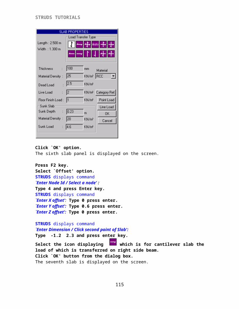
STRUDS TUTORIALS
{X-1.7} Saving Floor Plan
Select ‘Floppy’ option from the menubar.Select ‘Save’.
A dialog-box appears on the screen.Type `sample’ in the field for ‘File Name’.Select ‘Strudwin’ folder and select ‘Data’ folder in it.Select ‘Save’ button
Select ‘Floor’ option from the menu.Select ‘Pre-Analysis Enquiry’ option.STRUDS displays ‘Pre-Analysis Information dialog box’
115
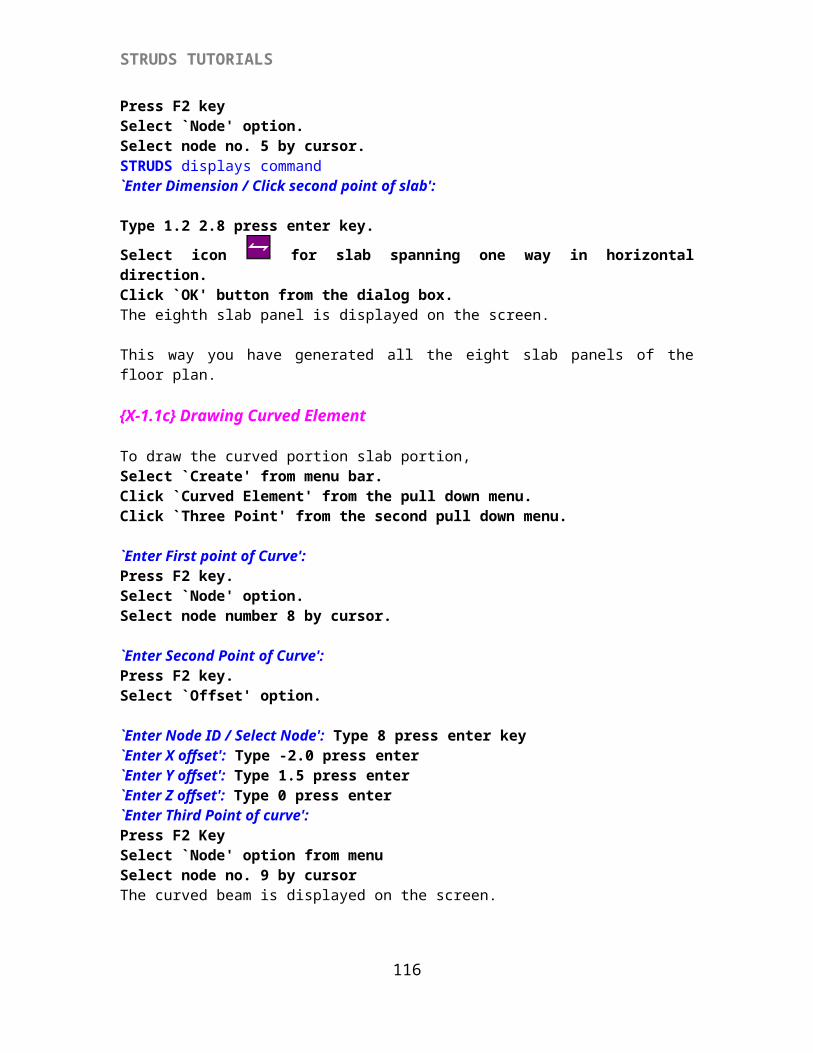
STRUDS TUTORIALS
Here we get the information regarding boundary conditions, whether they are defined or not. Are the elements are attached with sections, material or any zero length element formed.Note that the three list boxes should be empty. Otherwise do the necessary corrections.Click ‘OK’
Select ‘Floor’ option from the menu.Select ‘Analysis files’ option.Select ‘All levels’ option.Click ‘Save’ button.
Select ‘Floor’ option from the menu.Select ‘Close’ option.Now this window will disappear. And the first window of PreProcessor will reappear on the screen.
{X-1.8} Copying the Floor Plans In STRUDS once you define a floor plan, you can copy it for other floors. Then you can select any floor and make changes in that floor as per your requirement.
Select ‘Floor Plan’ from the menu.Select ‘copy’.
A window appears on screen having a series of fields which allows you to copy the floor plan from one floor to other floor.
The Source Floor No. is 1By default the Destination Floor No. is ‘New’. Click the dropdown arrow of the Destination Floor No.Select 2Click ‘OK’ button of the dialog box. The floor plan of Floor 1 is copied at ‘Floor No.2’.
Again select ‘Floor Plan’Select ‘Copy’ optionClick the dropdown arrow of the Destination Floor No.Select 3
116
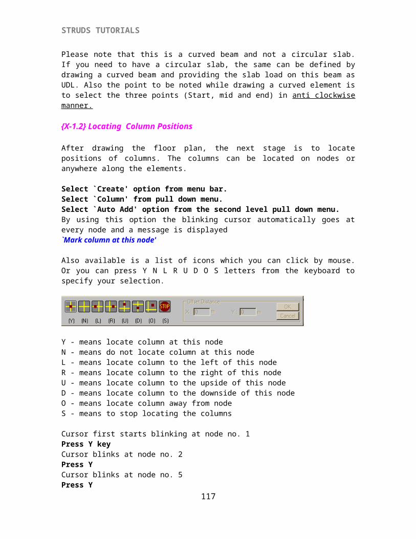
STRUDS TUTORIALS
Click ‘OK’ button of the dialog box.The floor plan from Floor 1 is copied at ‘Floor 3’.In this way copy the Floor 1 to ‘Floor 4’ and ‘Floor 5’
{X-1.9} Editing The Floor Plans
We can now change the data in any particular floor by selecting and editing that floor level.
Select ‘Floor Plan’.Select ‘Set’.Select ‘1’ from the pull down menu.Select ‘OK’ button.
The floor plan at bottom most level or level1 is displayed on the screen. Let us assume that this ‘Sample’ building has plinth beams at first level. Which means that there are no slabs in this plan (or) the load of slabs in this plan is not transferred on the beams. In other words, the beams are designed only for their self weight and imposed loads like wall load. To accomplish this, follow the below procedure.
Select ‘Property’ from menu bar.Select ‘Load’.Select ‘Slab-Beam Loads’.
A window displaying a small box to on/off flag is displayed.
By default the flag for ‘Compute Loading from slab to beam automatically’ is always on.
Click the check box by mouse to put the flag ‘off’.Select ‘Close’ button.Now in this particular floor plan, STRUDS will not consider the loads from slab to elements.
Select ‘Edit’ from menu bar.Select ‘Delete’.
117
STRUDS TUTORIALS
Select ‘Slab’.A box type cursor appears on the screen.
Delete the slabs S7 and S8 by moving cursor on these slabs and clicking the left button of mouse.STRUDS gives a warning message
Click the ‘OK’ button for both slabs S7 & S8.
Now to delete the curved element
Select ‘Edit’Select ‘Delete’Select ‘Element’Select any element in the curved beam by moving cursor along them and clicking the mouse.As there is no sunk at the last slab as being a terrace follow the next steps.Select 'Edit' from menu bar.Select 'One Slab' option.Select the Slab 'S4' by clicking on it with box cursor.STRUDS will display the 'Slab Property' window.
118
STRUDS TUTORIALS
Click 'Sunk Depth' box from the Sunk Slab option and enter ' 0.0'Click ' Material Density ' box from the Sunk Slab option and enter ' 0.0'Click 'OK' button.
Select 'Edit' from menu bar.Select 'One Slab' option.Select the Slab 'S5' by clicking on it with box cursor.STRUDS will display the 'Slab Property' window.
Click 'Sunk Depth' box from the Sunk Slab option and enter ' 0.0'Click ' Material Density ' box from the Sunk Slab option and enter ' 0.0'Click 'OK' button.
Select ‘Property’ from menu barSelect ‘Create’Select ‘Section’Select ‘New’ buttonSelect ‘Rectangular’ from the pull down menu. Type ‘230’ in the field of b Type ‘380’ in the field of d.Select ‘Save’ button.You have created a new beam section Select ‘Close’ buttonSelect ‘Property’ from the menu bar.Select ‘Attach’Select ‘Section’Select ‘Sec4’ from the pull-down menu Select ‘All’.STRUDS gives a warning message.
Select ‘Yes to All’ button from the message box.Now the new section Sec4 is attached to all the elements. The program overwrites the previously attached sections.
The building file is saved by using this option.
Select ‘Floor’ from menu bar.Select ‘Change Floor’ option.STRUDS displays 'SELECT FLOOR 'window.Select 'Floor 5'Select ‘OK’ button The floor plan of 5th floor i.e. top floor is displayed on the screen.
119
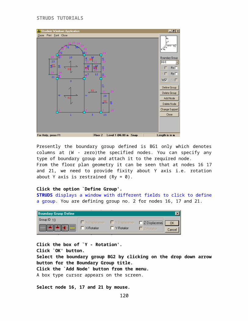
STRUDS TUTORIALS
Select ‘Edit’ from menu bar.Select ‘Delete’.Select ‘Slab’.Select slab S1 by moving the cursor on this slab and clicking mouse. STRUDS displays warning messageClick ‘OK’
Select ‘Edit’ from menu bar.Select ‘Delete’.Select ‘Column’ & click the mouse.Select column no. 1 by the cursor and clicking the mouse.
Select ‘Edit’ from menu bar.Select ‘Delete’.Select ‘Node’ & click the mouse.Select Node No. 1 by the cursor and clicking the mouse.
As there is no sunk at the last slab as being a terrace follow the next steps.Select 'Edit' from menu bar.Select 'One Slab' option.Select the Slab 'S4' by clicking on it with box cursor.STRUDS will display the 'Slab Property' window.
Click 'Sunk Depth' box from the Sunk Slab option and enter ' 0.0'Click ' Material Density ' box from the Sunk Slab option and enter ' 0.0'Click 'OK' button.
120
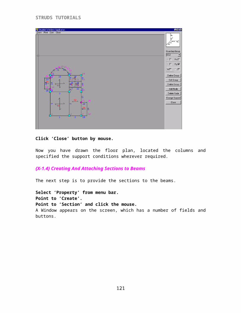
STRUDS TUTORIALS
Select 'Edit' from menu bar.Select 'One Slab' option.Select the Slab 'S5' by clicking on it with box cursor.STRUDS will display the 'Slab Property' window.
Click 'Sunk Depth' box from the Sunk Slab option and enter ' 0.0'Click ' Material Density ' box from the Sunk Slab option and enter ' 0.0'Click 'OK' button.
Considering there is parapet wall on fifth slab we have to detach the wall load from it and then to attach the parapet wall load.Select ‘Property’ from menu bar.Select ‘detach’.Select ‘Wall’ & click by mouse.A window is displayed on the screen
Select ‘All’ from ' Select Wall ' from the menu.Select ‘All’ from ' Select Elements ' from the menu.Select ' Detach from selected element 'STRUDS displays the following window
Click ' Yes ' button.Select ‘Close’ button of the ' Detach Load ' window.This way you have removed the loads from all the walls on elements in this floor.
121
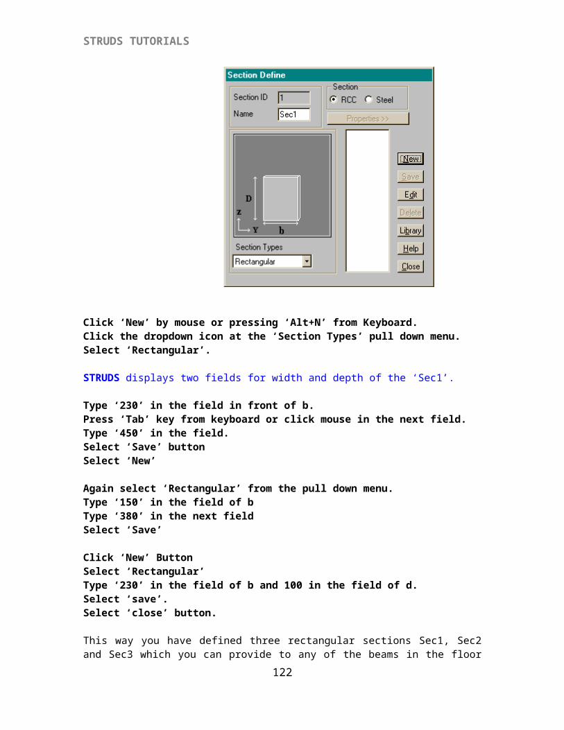
STRUDS TUTORIALS
Select 'Property' from menu barSelect 'Attach' option.Select 'Wall' sub-option.STRUDS will display 'Attach Loading Wall' window.Select 'Wall 3' from the dropdown bar.Click 'Locate' button.Select the elements 1,3,23,24,26,31,14,16,17 and 2,9,19,22,21,20 by using the box cursor.Click 'Curve' button.Select any element of the curved beam and click on it with the box cursor.Click 'Close' button of 'Attach Loading Wall' window.
Select ‘Floor’ from menu bar.Select 'Generate Wall Loads'STRUDS displays a message ‘Wall load generation is completed’Click ‘OK’
Select ‘Close Floor’ option.This way you have created all the five floor plans for sample building.
Now the main window of PreProcessor will reappear on the screen.
{X-1.10} Setting Column sizes and Orientation of Columns
Select ‘Column’ option from menu bar.Select ‘Set Parameters’ option.STRUDS displays ‘Set Column Dimensions’ dialog box.
The default width and depth are taken as 230mm. You can change this by overwriting in the fields. This means that at the uppermost floor column, the size of column is 230m x 230mm.
122
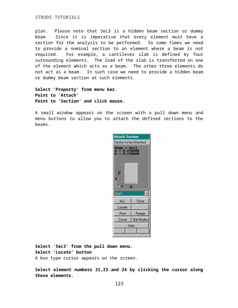
STRUDS TUTORIALS
Select the `Increment' option given below the Column sizes title. The other fields below this are activated.The default increment is 75mm. Which means that after every floor the from top, the depth of column is taken as 230 + 75 = 305mm, 305 + 75 =380mm etc. So the column sizes shall be 230 x230, 230 x 305, 230 x 380...from top to bottom. Similarly you can specify the parameters and STRUDS will take column sizes accordingly.
Select `Close' button.Select `Column' - `Generate' option.STRUDS takes the sizes of columns as the parameters specified by you.
Select `Column' Select `Orient' option. STRUDS displays a new screen with a menu bar and some buttons and icons at the right hand side. You can use these options to specify the orientation of column. You can also change the sizes of any column. The icons at the top right are to specify the flushing of column with respect to beams.
Suppose you want to change the orientation of a column -
Select `Select Column' button.Select the column by cursor.That column is displayed on screen in an enlarged manner.
Select `Rotate' optionClick anywhere in the screen.
123
STRUDS TUTORIALS
Now you can rotate the column by pressing enter key repeatedly. You can select the horizontal and vertical position of column as per your discretion. You can also flush the column with beam by clicking the icons at top right.
Select `Shape & Size' button.STRUDS displays a small window. You can select any column by using the drop down list menu of column group.
Select `Column Sizes' button.STRUDS displays the floor wise sizes of selected column. The basic parameters as specified in `Column' -`Set Parameters' option are also available at bottom. You can change these parameters for this column. Or you can select the floor and overwrite the sizes in the fields provided for width and depth for that floor. For example -
Select floor no. 1 by double clicking the mouse. Overwrite 750 in the field provided for depth.(optional)Select `Save' button.STRUDS automatically computes the sizes for remaining floors.Similarly you can change the sizes for other columns. If you do not want the sizes to be computed automatically as per parameters; you can simply put off the Autosizing option by clicking its check box and overwriting the sizes at every floor.
124
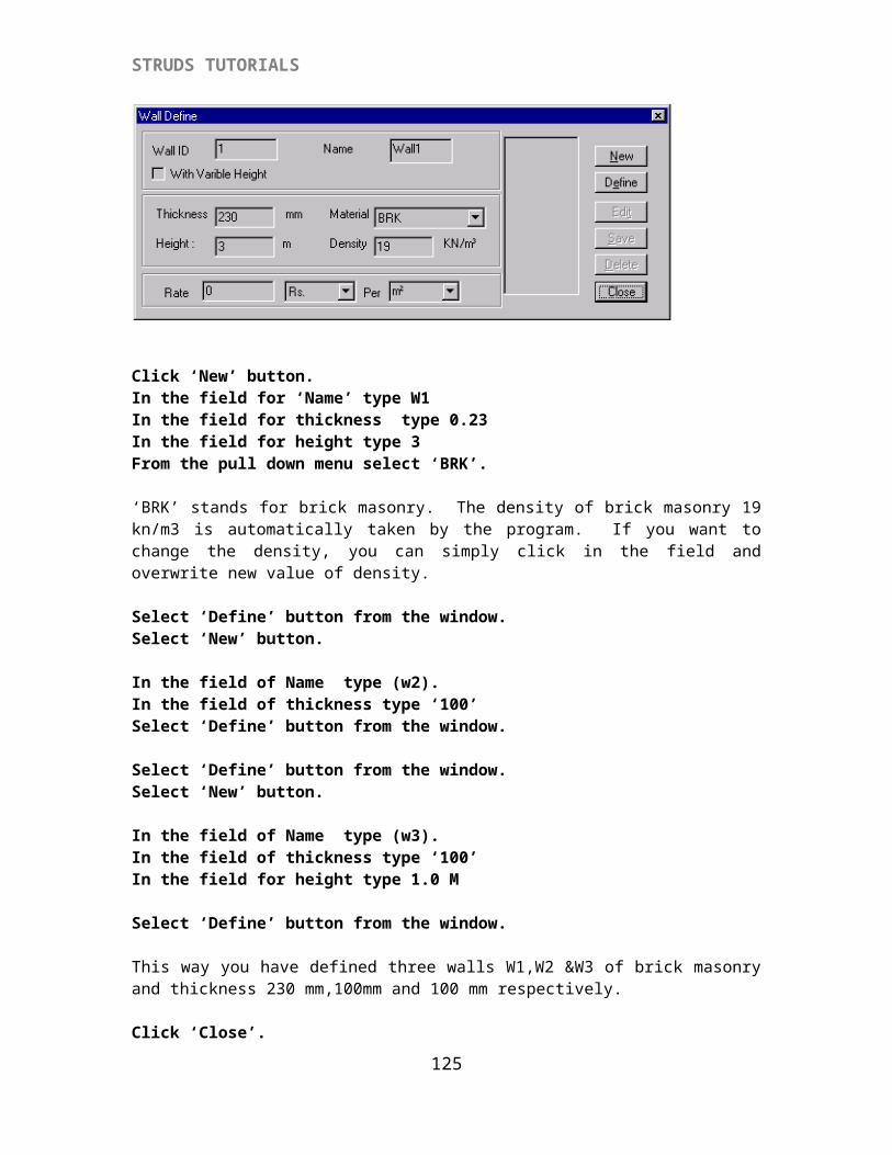
STRUDS TUTORIALS
Select `Save' button.Select `Close' button.Select `Close' button.Select `Close' button.
Select ‘Floor plan’ from menu bar.Select ‘Analysis Files’.Select ‘All’.
STRUDS displays a window where you can specify the directory in which you want to store these analysis files.
Select ‘Save’ button.Select 'Building' from menu barSelect 'Exit'STRUDS displays a message box
Click 'Yes' button.Now the main window of STRUDS will appear on the screen.
{X-2} Analyzing the Building Structure
In STRUDS, the building can be idealized as Plane Grids, Plane Frames or Space Frame. By defining the floor plans per floor, you have specified the floor grids for each floor. You can now analyze and design this sample building by following three methods.
1. PLANE GRID METHOD - In this method the beams shall be designed as continuos beams with end supports as simple supports and the intermediate supports as continuos supports. The columns and footings will be designed for axial load only. Slabs will be designed as panels.Many consultants for low-rise buildings adopt this method with simple grid like floor plans.
2. PLANE FRAME METHOD - STRUDS automatically generates the plane frames in X and Y direction and analyses them in one stroke. The analysis results are automatically taken to design. The stiffness of columns is also taken into account in the analysis. Beams are designed as continuos beams with fixity at end supports. Columns will be designed for axial load and moments in X and Y directions. Footing shall also be designed for biaxial bending. Also in this method STRUDS can automatically generate horizontal loads like Wind Load and Earthquake Loads on the frames as per the basic parameters provided by the user.
This method is used by most of the consultants for multistoried building where analysis for horizontal loads is desired and the floor plans are such that the plane frames are distinctly generated. However where the plans are irregular and frames are not generated along all primary
125
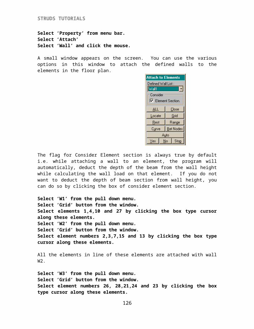
STRUDS TUTORIALS
beams, this method may prove to be erroneous. For example if a grid has only one column, the frame can not be generated.
3. SPACE FRAME METHOD - STRUDS automatically generates and analyses the space frame. The results are then automatically taken to design module for design. The stiffness of columns is taken into account for analysis. Beams are designed as continuos beams with fixity at end supports. Columns will be designed for axial load and moments in X and Y directions. Footing shall also be designed for biaxial bending. Also in this method STRUDS can automatically generate horizontal loads like Wind Load and Earthquake Loads on the frames as per the basic parameters provided by the user.
This is the most accurate and desirable method for analysis and design. This method is difficult to adopt for manual calculations, but is most suitable for computer aided design.
Plane Grid Method
{X-2.1} Analysis
Select `Building' from the menu bar. Select `Exit'A message box 'Save changes to sample?' will appear on the screen.Select 'Yes' button of the massage box.
The main menu of STRUDS appears on the screen.
Select `Analysis' from the menu bar.Select `Open 'Select `Building File'STRUDS displays a box showing the *.ctl files. The *.ctl file is the file for every building project which contains data for analysis.
Select `Sample.ctl' file.Select `Open' button.Select `Analysis' from the menu bar.Select `Floor Grid'
STRUDS displays a message box containing the files for analysis. Every floor has a separate file for analysis. Please note that Samp011 means that floor grid data file for first floor first level. Similarly samp021 means floor grid data for second floor 1st level. In STRUDS a floor can have more than one level ( as incase of stilt floor ). In such building a floor may have more than one files.
126
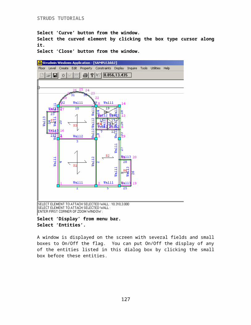
STRUDS TUTORIALS
Select `Add All' button.Select `OK' button.STRUDS performs the floor grid analysis for all files.STRUDS displays a message.
Select `OK' button.
Now if you want to see the analysis results, you can operate the PostProcessor module. If you do not want to see the analysis results, you can directly go to the Design option by using control menu of STRUDS
{X-3} DESIGN BY PLANE GRID METHOD
Select `Design' from the menu bar.STRUDS displays the 'Design Windows Application' menu.
Select `File' from menu bar.Select `Open' button.Select `sample.bld' from the message box.
127
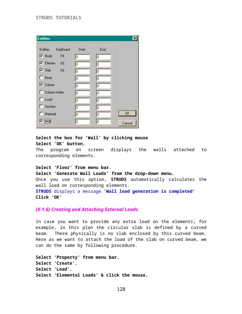
STRUDS TUTORIALS
The bottom most floor plan of the sample building is shown on the screen. The menu bar displays the various design modules.
{X-3.1} Slab Design
{X-3.1.1} Defining PropertiesSelect `Slab' from the menu bar.Select `Properties' from the pull down menu.STRUDS displays a dialog box where you can specify the design parameters fro slab design.
The default parameters are as shown in the dialog box.
Select `Reinforcement Parameters' button.STRUDS displays another dialog box which indicates the parameters like concrete cover, maximum and minimum spacing criteria and type of bars to be used for design. You can change any of these parameters by overwriting your value in the corresponding fields.
128
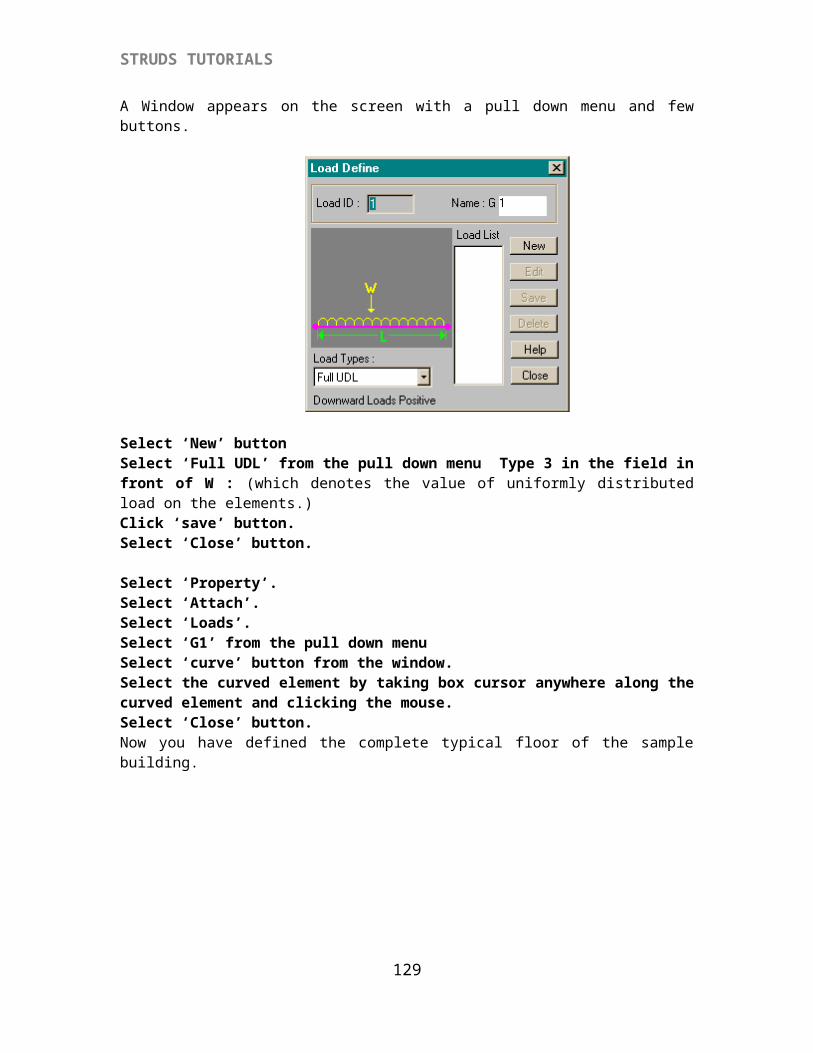
STRUDS TUTORIALS
Select `OK' button.Select `OK' button.
Select `Slab' from menu bar.Select `Level Design' option.
You can select any level for which the slabs are to be designed.
Select floor no. 2 from the drop - down menu.Select `OK' button.STRUDS displays the floor plan of second floor on the screen.You are now in the Slab design module.
Select `Design' from the menu bar.Select 'New'Select 'All'
STRUDS starts designing all the slabs in this floor one by one. If any slab fails in design. STRUDS displays a warning message.
129
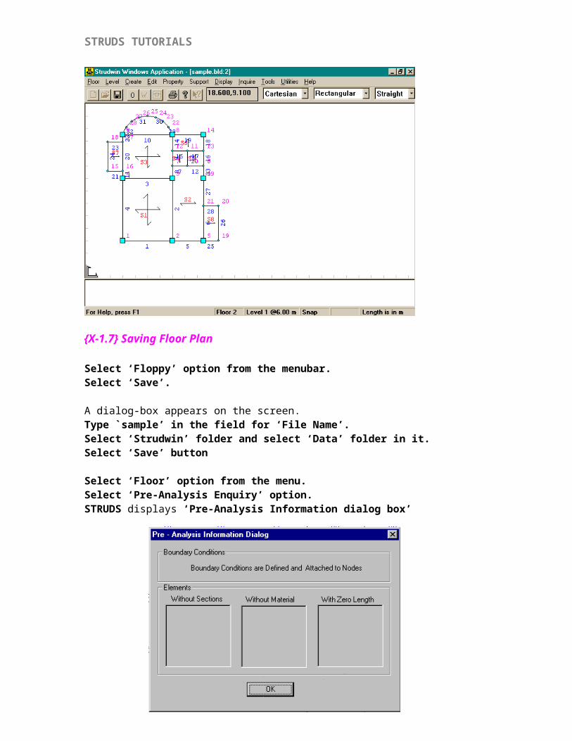
STRUDS TUTORIALS
When a slab fails in deflection, you can (i) Ignore the check : in this case the program will increase the steel area to control deflection by adjusting the base factor.(ii) Increase the thickness of slab(iii) Increase the grade of concrete
Select `Change Thickness' button and change the thickness to 130 mm.Click 'OK'STRUDS designs all the slabs.
Select `Group' from the menu bar.STRUDS automatically puts the slabs having similar reinforcement in one group. In the sample floor plan the slabs S4, S5 and S6 are taken in one group.
{X-3.1.2} Displaying Slab Design Results
Select `Report' from the menu bar.Select `Schedule'
130
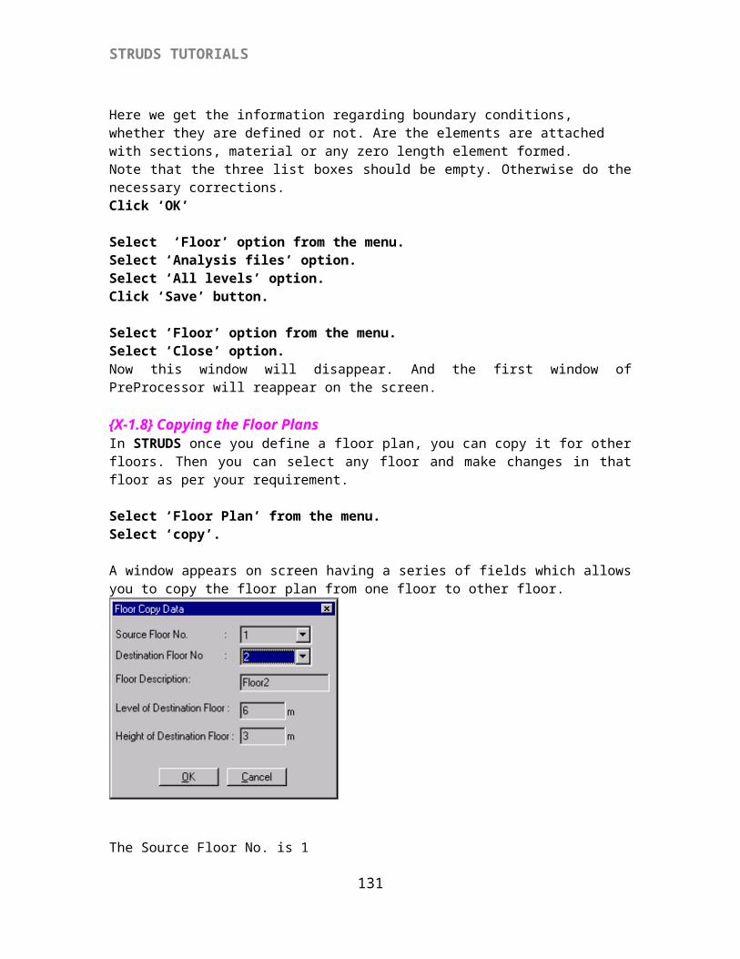
STRUDS TUTORIALS
STRUDS displays the schedule for reinforcement to be provided for every slab. You can print this schedule by using the `Print' option from the menu.
Select `Close' option from the menu bar.Select `Report' from the menu.Select `Design Sketch All' option.STRUDS displays the sketch for reinforcement bars provided in all the slabs. You can get a print of this by using `Print' option from the menu bar.
131
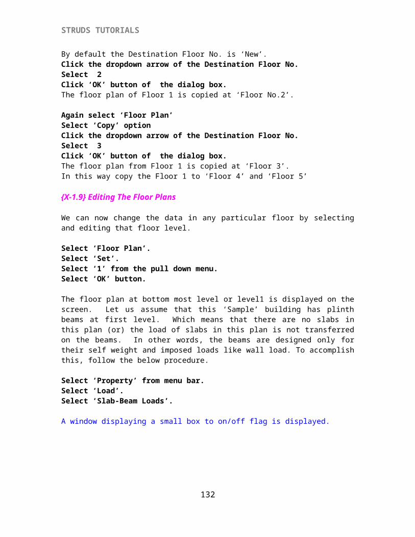
STRUDS TUTORIALS
Select `Report' from the menu. Select `Plan' STRUDS again displays the floor plan of second floor.
Select `Report'Select `Detail' A box cursor appears on screen. You can select any slab of which the design details are to be seen by moving this cursor along the slab and clicking mouse.
Select Slab S1 by cursor.STRUDS displays a window showing the design details of this slab. You can change the diameter of reinforcement if required. STRUDS will then automatically change the spacing of bars. This change will automatically be reflected in schedule, design sketch and quantity reports.
132
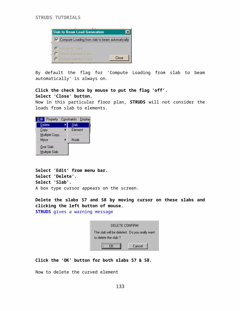
STRUDS TUTORIALS
Select `OK' button.Select `Report' Select `Quantity'STRUDS displays a report of steel and concrete required for all the slabs. You can print this report by using the `Print' option from the menu.
Select `Close'If you want to see the support and midspan moments of any slab, you can adopt the following procedure.
Select `Inquire' from the menu.Select `Moments All' option.
133
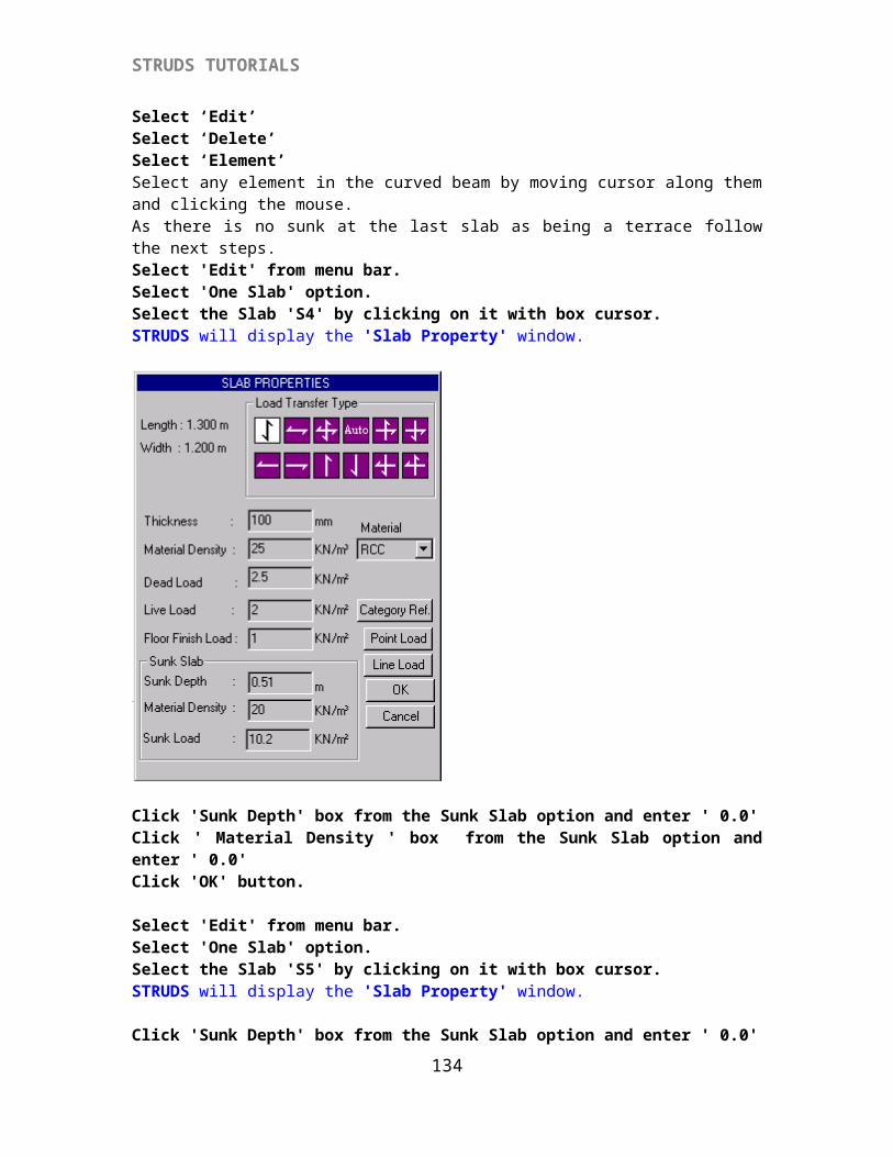
STRUDS TUTORIALS
STRUDS displays slab plan with moment values.
Select ' Change Floor' from the menu bar.STRUDS will display the following dialog box.
Select 'Floor ID'Select 3Click 'Design'Select 'New'Select 'All'STRUDS will display the message box.
Click 'OK' and proceed to the next steps as described above.
134
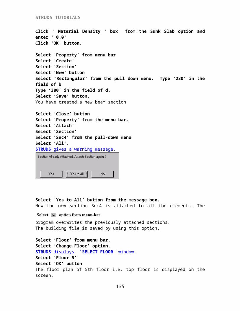
STRUDS TUTORIALS
In this way follow the above all steps to design the remaining floor slabs.
Select `Close' from menu to come out of the slab design module.
STRUDS design application menu appears on screen.
{X-3.2} Beam Design
{X-3.2.1} Defining Beam Properties
Select `Beam' from the menu.Select `Properties' from the menu.STRUDS displays a window with several fields and buttons to specify the basic parameters for beam design. You can change any of the parameters in the field by overwriting your value.
Select `Reinforcement' button.STRUDS displays another window to specify the reinforcement parameters. You can again change these parameters as per your discretion.
135
STRUDS TUTORIALS
Select 'Stirrup Grade': Fe250Select 'Stirrup Dia' : 6 mm
Select `OK' button.Select `OK' button.
Select `Beam' from the menuSelect `Plane Grid' option. STRUDS displays the 'Select Level' window.
Select floor 1 from the pull down menu.The floor plan of second floor appears on the screen.
Select `Design' from the menu bar.Select `New'STRUDS displays the following window.
Select `OK' button.STRUDS designs all the beams in this floor plan.Select 'Grouping' option from the menu bar.Select `Auto'STRUDS will automatically group the beams.
Select `Marking' option from the menu.
136
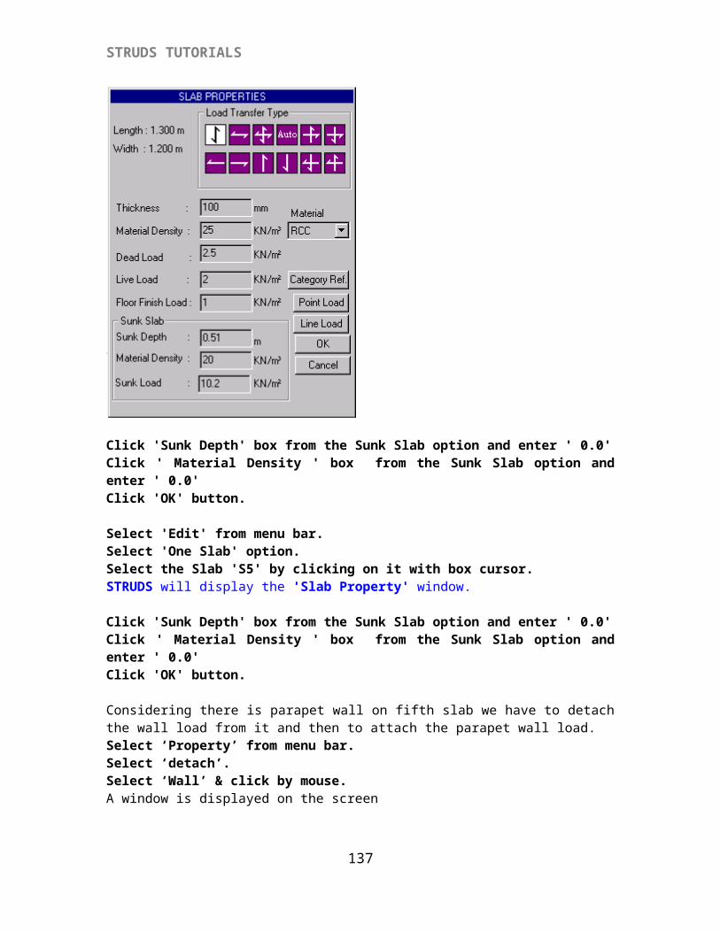
STRUDS TUTORIALS
The beam plan before marking is
Select `Auto' option.This is an important option. In a floor plan a beam may have more than one element. In such case STRUDS labels each element separately. For example the beam from column C3 to C6 has two elements. So STRUDS provides two labels B19 and B20 to these elements. When you use Marking - Auto option, STRUDS automatically finds out the beams, which have more than one element, and provides a single label to that beam. The schedule and quantity reports are changed accordingly.
The beam plan after ‘Marking' is
137
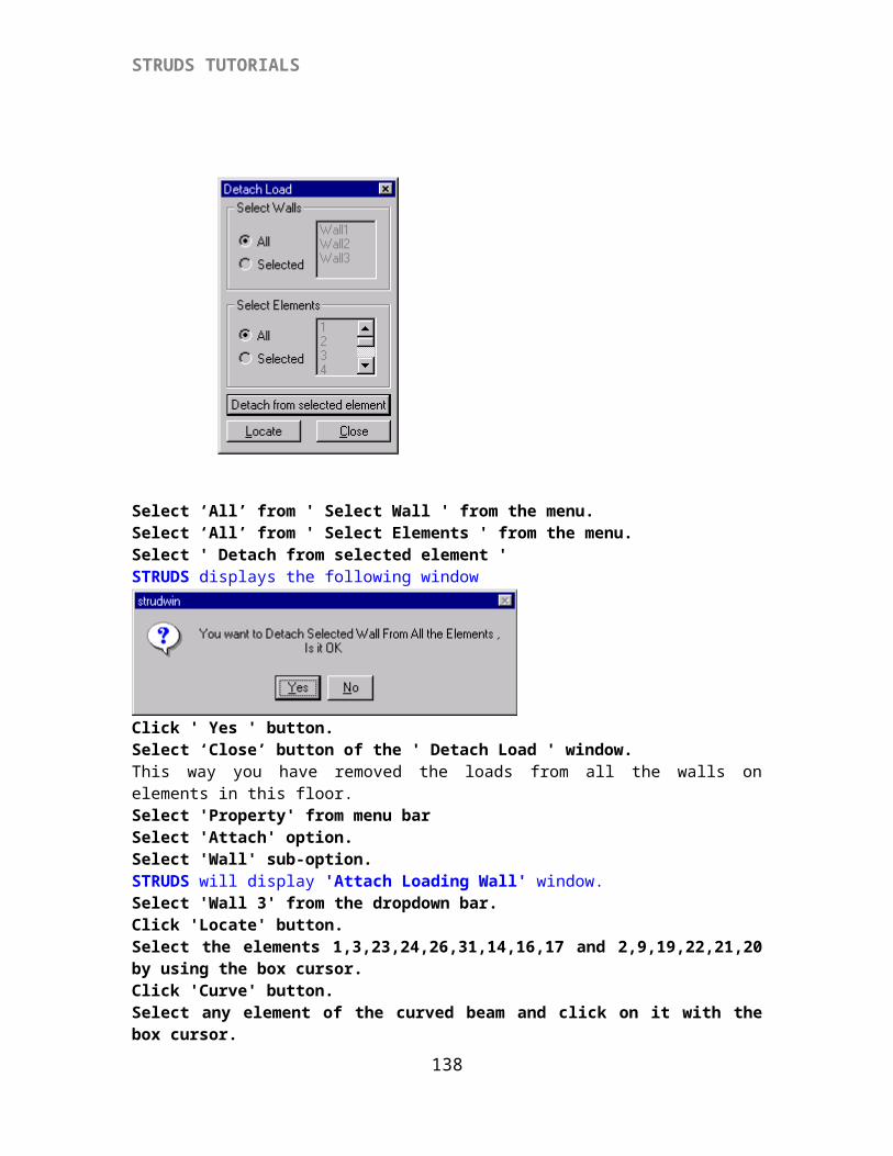
STRUDS TUTORIALS
In some cases if the beams have more than one element and you have attached different sections to those elements, STRUDS can not merge the elements to form one single beam. So you should take care while attaching sections that a beam having more than one element should have uniform section for all its component elements.
In some cases, the program is not able to judge from the analysis results whether the elements should be merged together to form a single beam. In such cases, you can use your own judgement and mark the beams by using `Marking' - `Manual' option from the menu.
{X-3.2.2} Displaying Beam Schedule
Select `Report' from menu.Select ` Group Schedule'STRUDS displays the design group schedule for all beams. You can print this schedule by using the `Print' option from the menu.
138
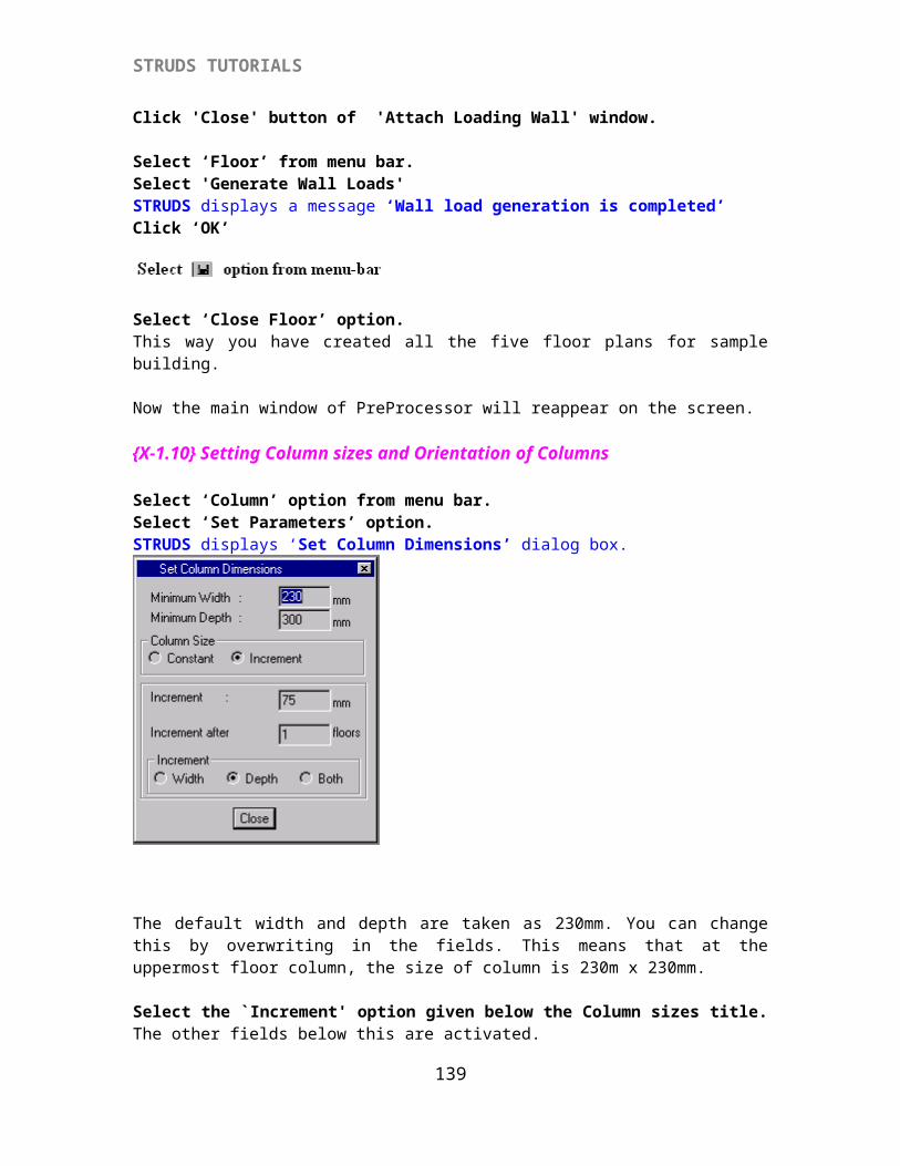
STRUDS TUTORIALS
Similarly you can view / print the 'Beam Schedule' from the Report option.Select `Close' from the menu.
{X-3.2.3} Displaying Bar Bending Schedule
Select `Report' from menu bar.Select `Bar Bending' option.STRUDS displays the bar bending schedule report for all the bars in every beam. The shape of bar types is also indicated at the end of this report.
139
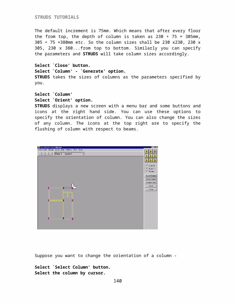
STRUDS TUTORIALS
Select `Close' option.
{X-3.2.4} Displaying Beam Quantity Report.Select `Report' from menu.Select `Quantity' option.STRUDS displays a text report for the quantity of steel and concrete required for all the beams. You can obtain the print of this report by using `Print' option from the menu. You can also change the Units or the font sizes of text by using `Settings' option from the menu.
Select `Close' from the menu.
{X-3.2.5} Displaying Double Line Diagram
Select `Plan Layout' from the menu bar.Select `Double Line Diagram' option.STRUDS displays the key plan of the floor showing slab nos., beam nos., column nos. and width of beams. This is the plan most of the consultants are required to provide with the design schedule of beams.
140
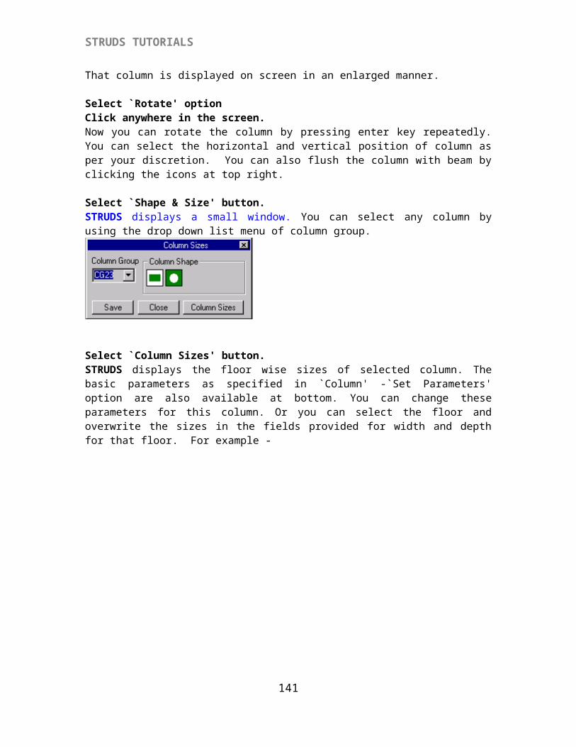
STRUDS TUTORIALS
Select `Plan Layout' from menu bar.Select `Double Line + Schedule' option.STRUDS displays the key plan along with the design schedule of beams. So you can view the beam nos and their corresponding design outputs on the same screen.
Now you can select any gridline (continuos beam) in the plan and see its analysis and design results.
{X-3.2.6} Displaying Analysis Results.
Select `SelectGrid' from menu.A box type cursor appears on the screen.
Select B1 by cursor.The entire continuos beam comprising B1and B2 appears on the screen. A menu is displayed at the top.
Select `Analysis Results' from menu bar.
141
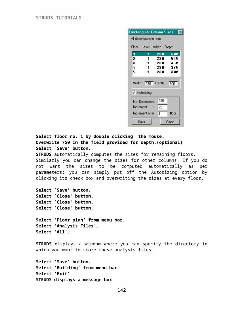
STRUDS TUTORIALS
Select `SF Diagram' option.STRUDS displays the Shear Force Diagram of the continous beam. The shear values are shown at the right hand side in a small window. STRUDS displays the SF values the first beam from left end. You can see the SF values of other beams by using the up and down arrows of the beam labels field.
Select `Analysis Results'.Select `BM Diagram'. STRUDS displays the Bending Moment Diagram of the continous beam. The bending moment values are shown at the right hand side in a small window. STRUDS displays the BM values the first beam from left end. You can see the BM values of other beams by using the up and down arrows of the beam labels field.
Select `Analysis Results' from the menu.Select `Common' option. This option allows you to visualise both BMD and SFD together STRUDS displays a window with check boxes.
Select the check boxes of GridLine, Shear Force and Bending Moment by cursor.
Select `OK' button.STRUDS displays the gridline and its SFD & BMD on the screen.
142
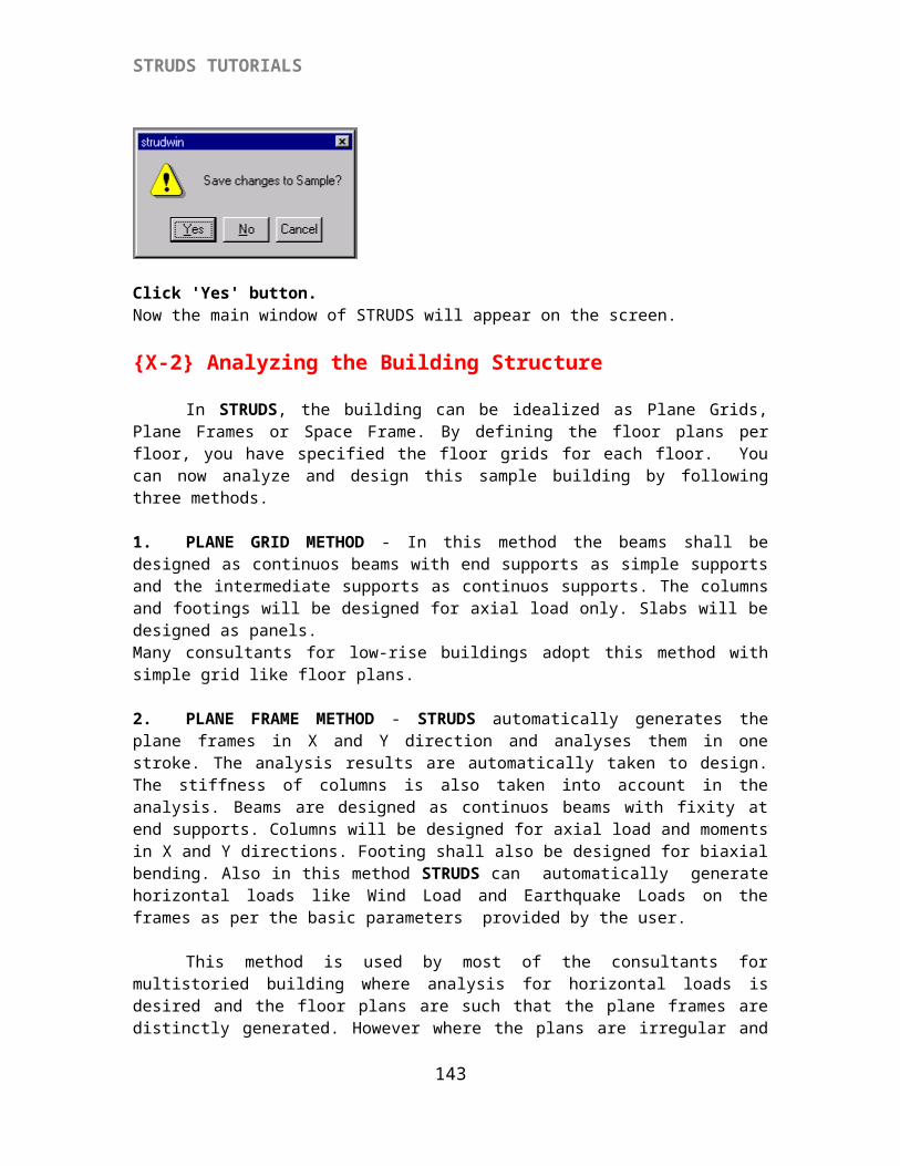
STRUDS TUTORIALS
Select `Close'Similarly you can use options `Def Diagram' and `Tor Diagram' to see the deflection diagram - values and torsion diagram - values of the selected gridline.
Select `Analysis Results'Select `Redist..' option.STRUDS displays a window with fields. This option is useful to distribute the moments in a beam. You can specify the percentage moment to be redistributed and STRUDS recalcultes the moments. The design of this beam shall be done according to these revised moments.
143
STRUDS TUTORIALS
Type 30 at the field for Left Node.Type 25 at the field for right node.Select `Redistribute' button from the window box.STRUDS displays the revised moments after redistribution. Similarly you can redistribute the moments for other beam spans.Select `Close' button.
{X-3.2.7} Displaying Design Results.
Select `Design Results' from menu.Select `Section Graphics' option.STRUDS displays the longitudinal section of the continuous beam. The cross section of beams is also displayed at the bottom half of the screen. STRUDS first displays the c/s of first beam from the left end at its support and midspan. If you want to see the c/s of next beam -
144
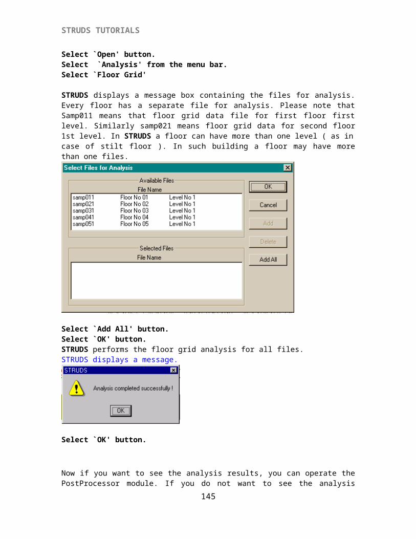
STRUDS TUTORIALS
Select `Cross Section' from menu.Select `Next' option.STRUDS displays the c/s of next beam span in the continuous beam. Similarly you can see the c/s of successive beams in a gridline.Select `Close' from menu.
Select `Design Results' from menu.Select `Properties' option.By using this option, you can change the properties of all or any beam in the selected gridline. STRUDS displays a window box with several fields and buttons.
145
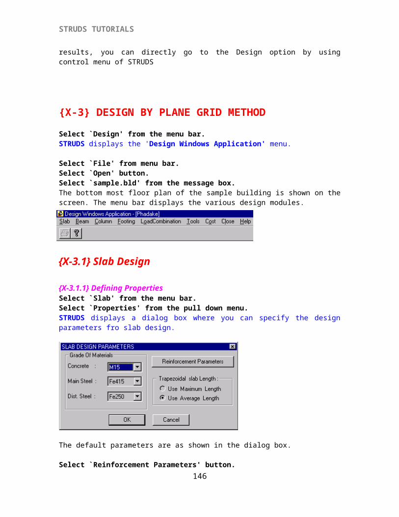
STRUDS TUTORIALS
Select `Ast Bot..' button.STRUDS displays the areas of steel required at eleven points in the beam. You can note down the maximum area of steel required.
Select `Close' button of the Design Values window.Now suppose you want to change the section of B1.
Select `Section Geometry' button.Overwrite the depth of section as 0.38 in place of 0.45 in the field provided for depth.(optional)
Select `OK' button.Select `Save' button.Select `Close' button.STRUDS now automatically redesigns the beam for the revised section. This change is automatically carried out in Schedule, Quantity, Bar Bending report and Section Graphics.
Select `Design Results'.Select `Section Graphics'.You can see the change in beam depth and corresponding change in reinforcement. Please note that here the analysis results remain same. The effect of change in analysis due to change in beam section is not considered. Only the design is changed as per revised section. If you want to take into account the effect on analysis due to change in section, you can change the section of that beam in preprocessor, reanalyze and redesign the beam.
Select `Close' from menu.Select `Close' from menu.The main menu of Beam design Module appears on the screen.
Select `Close' from the menu.STRUDS gives a warning message :
146
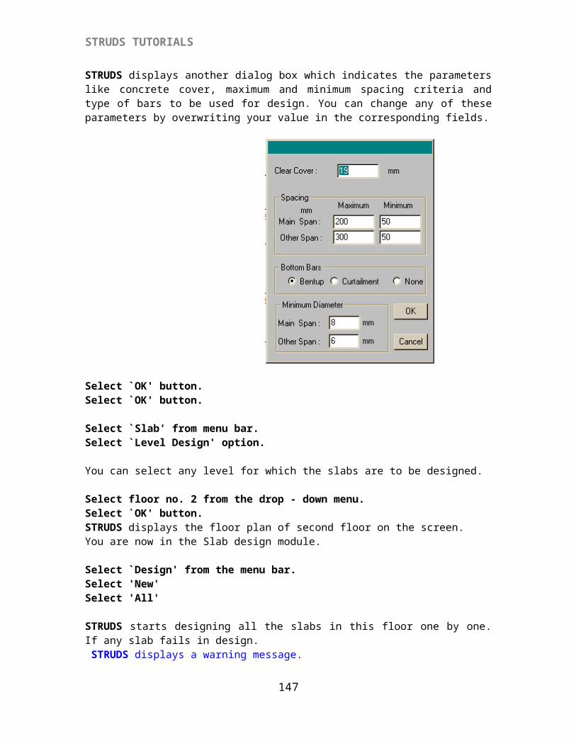
STRUDS TUTORIALS
`Save Changes to Design ?'
Select `No' button.This way you have designed the beams of first floor level. Similarly you can design beams for other floors.
{X-3.3} Column Design Now you can design columns for the Plane Grid Analysis results.
{X-3.3.1} Defining Properties
Select `Column' from menu.Select 'Plane Grid' option.STRUDS displays a window for column designing.
Select `Properties' option.A window appears on the screen with several fields and buttons. You can set the basic parameters like grade of concrete, grade of steel, minimum eccentricity, concrete cover etc. by using the options in this window.
You can also set the reinforcement parameters of the columns.Click 'Select Bar Diameters' button.STRUDS displays the following window.
147
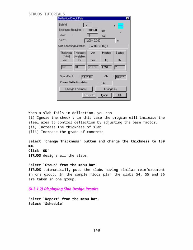
STRUDS TUTORIALS
Select the Bar Diameters from the 'Available' list by double clicking on the required bar diameter.Select 16, 20.Click 'OK'
Click on the check box for 'Change Size Internally'Click on the check box for 'Consider Live Load Reduction'
Select `Reinforcement Parameters’ button
You can change the parameters by overwriting the values in the field of this window.
Select `OK' button.
Select `Design' from menu.Select `New'Select `Biaxial' option.STRUDS designs all the columns for axial load and moments due to slenderness and minimum eccentricity. In case of Grid Analysis, the moments on columns due to beam connectivity are not taken into account.
In this sample building, we have specified the column sizes 230x230 mm ; for Grid design STRUDS will automatically compute the column sizes taking one side as 230 mm. The other dimension of the column is computed by the program from the axial load coming on the columns and axial load capacity of column section with one dimension as 230mm. You can however specify the column sizes by using option `Column' - `Orientation' from control menu of STRUDS or `Column' - `Orientation' option from main menu of Design module. Select 'Design'Select 'Save'
{X-3.3.2} Displaying Column Design
Select `View Design' option from the menu.Select the Column no. 5 by cursor.
148
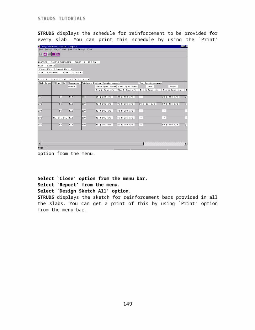
STRUDS TUTORIALS
STRUDS displays a window showing the floor-wise design results of column no.5. The floor nos, axial load on column, the moments on column in X and Y direction, grade of concrete, grade of steel, dimensions of columns, reinforcement provided, area of steel required, percentage of steel etc. are shown in the tabular form. You can also change the section and redesign the column.
Select the field of depth for floor-1 by cursor.Overwrite the previous depth 530 by new depth value 600.(optional)Select 'save' button.Select 'Redesign' button.
STRUDS automatically redesigns the column for revised section and provides the steel accordingly. Similarly you can change the bar diameters and STRUDS will automatically recalculate the no. of bars required.Select 'Close' button.
{X-3.3.3} Displaying Cumulative Loads
Select 'View loads' from menu bar.Select 'Cumulative loads'.Select 'Floor 1' from the pull down menu.STRUDS displays the total loads coming on each column at the bottom-most floor level. The loads are shown in KNS.
{X-3.3.4} Displaying The Centerline Plan
Select 'Center Line' from menu.STRUDS computes the centerline distance of all the columns in both X and Y directions, from the origin.
149
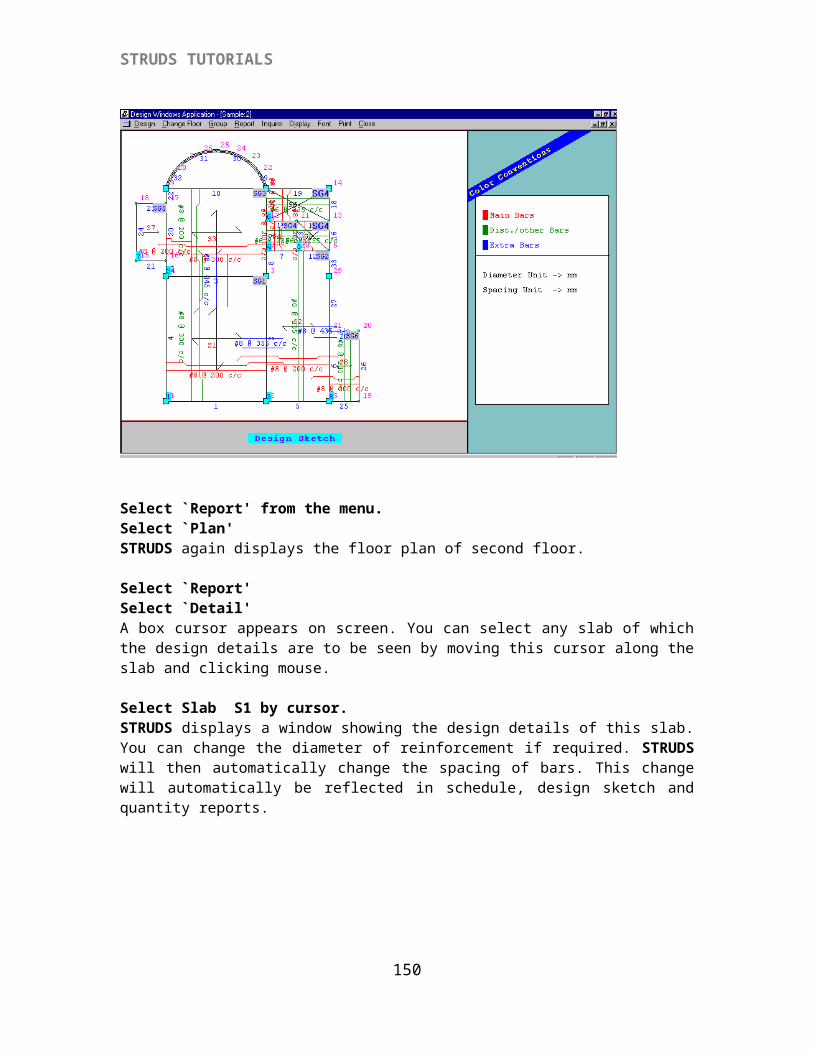
STRUDS TUTORIALS
Select 'Cross Section' from the menu.Select any column by cursor.The cross section of that column at bottom most floor is shown on screen. STRUDS also displays the reinforcement provided in the column. You can change the floor no. in the pull down menu to see the corresponding cross section of the column.
150
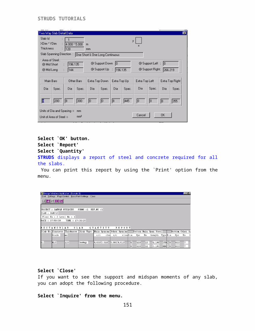
STRUDS TUTORIALS
Select 'Close' from menu bar.
{X-3.3.5} Displaying Column Design Results
Select 'Report' from menu.Select 'Column Schedule' option.Select 'Floorwise' option.STRUDS displays the column design schedule for all the columns. Floorwise sizes, reinforcement of main bars, stirrup steel and grade of concrete is shown in the schedule. You can obtain a hard copy of this schedule by using 'Print' option from the menu.
151
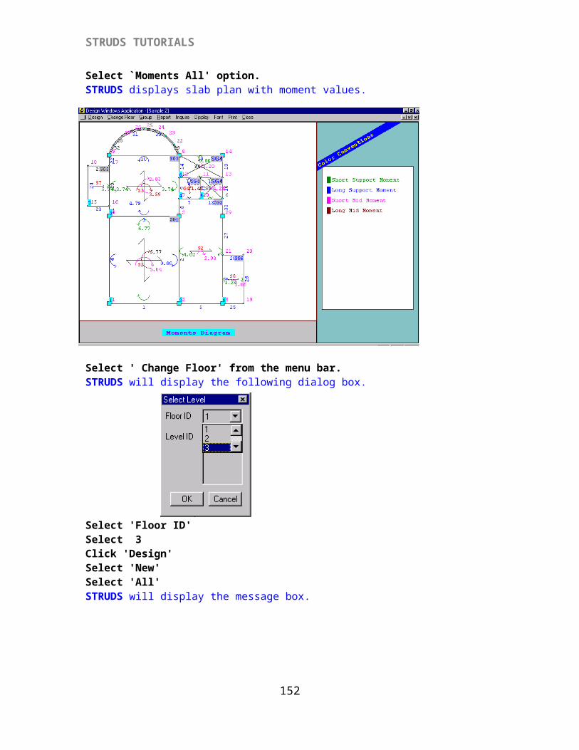
STRUDS TUTORIALS
Select 'Close'.Select 'Report' from menu.Select 'Column Quantity' option.STRUDS displays the concrete and steel quantity required for all floors and all columns.
Select 'Close'
{X-3.3.6} Displaying Quantity Summary
Select 'Report' from the menu.Select 'Quantity Summary' from the menu.
STRUDS displays the summary of overall quantities of concrete, diameterwise steel and shuttering area required per floor of the building for every column.
152
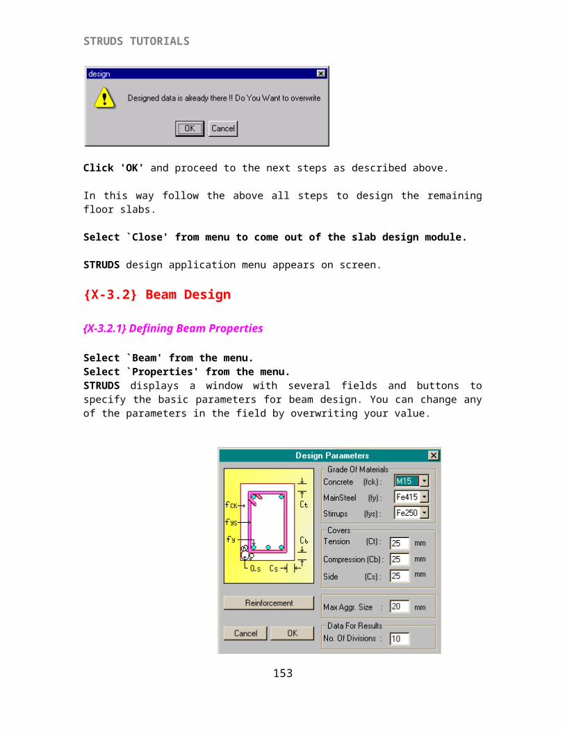
STRUDS TUTORIALS
Select 'Close' from the menu.
{X-3.3.7} Displaying Column Load Report
Select 'Report' from the menu.Select 'Column Load' option.
STRUDS displays a report of loads coming on the column at every floor.
Select 'Close'.Select 'Report'.Select 'Column Design' option
STRUDS displays a text report of column design details. All the basic parameters for designing are displayed in this report.
Select 'Close' option.Select 'Close' from menu to come out of the column design module.The main menu of Design windows application again appears on the screen.
{X-3.4} Footing Design Select 'Footing' from the menu bar.Select 'Plane Grid' method.
{X-3.4.1} Defining Design Parameters
Select 'Properties' option.
153
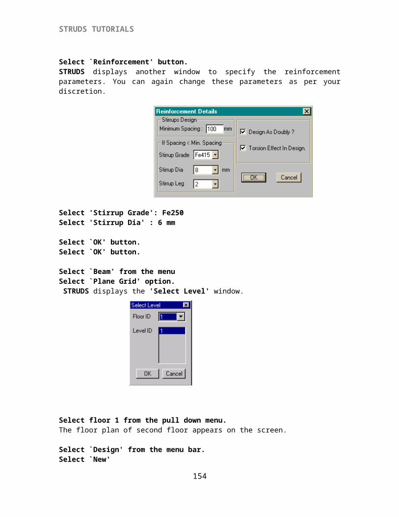
STRUDS TUTORIALS
STRUDS displays a window having several fields and buttons. You can specify by the basic parameters for footing design by exercising different options provided in this menu.
Select 'Select Bar Diameter' button.STRUDS displays 'Select Bar Diameter' window.STRUDS selects bars of diameters 8mm, 10mm, 12mm by default.Select ' 8 mm' bar from the 'Selected' list.Click 'Deselect' button.Select '12 mm' bar from the 'Selected' list.Click 'Deselect' button.
Select 'Soil Parameters' button from the window. STRUDS displays 'Soil Parameters' window
154
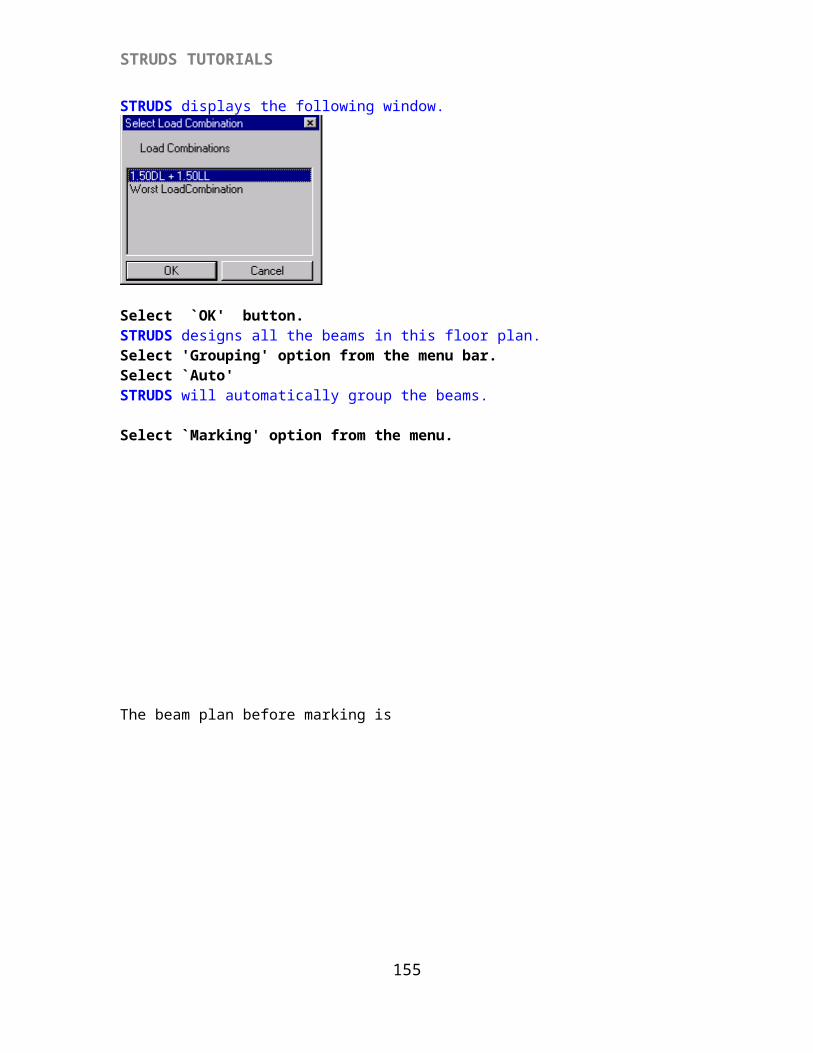
STRUDS TUTORIALS
You can change the bearing capacity of the soil if needed.Select 'OK' button.Select 'OK' button from the Design Parameters window.
Select 'Design' from menu bar.
STRUDS designs all the footings in one stroke. If any footing fails for any of the design checks, STRUDS displays a warning message box. In this case the bond check for column bars fails.
Select the 'For All Group' optionSelect 'Depth' button from the Change option.
Select the 'For All Group' optionSelect 'Size' button from the Change option.
Select the 'For All Group' optionSelect 'Size' button from the Change option.
STRUDS completes the design for all the footings.
{X-3.4.2} Displaying Footing Design Results
Select `View Design' from menu.Select any of the footings by cursor. STRUDS displays the design results of that footing on the screen. The X and Y dimensions of the footing, edge depth, main depth and steel provided are shown in the window box. You can also change one of the dimensions of footing. STRUDS will then automatically redesign the footing and calculate the steel required for the revised size.
155
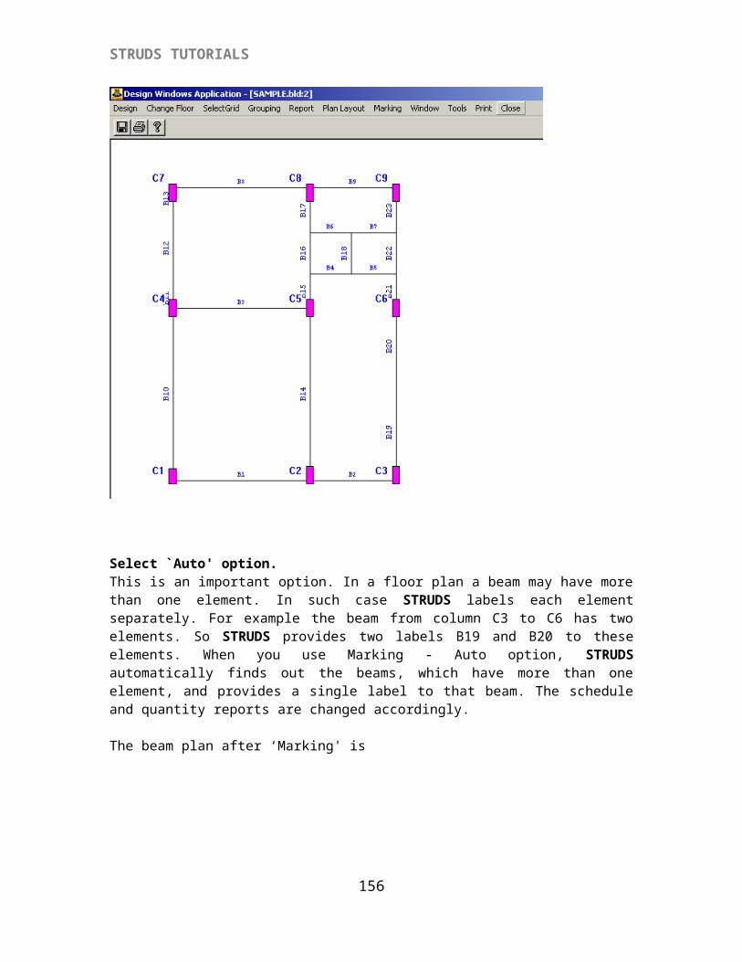
STRUDS TUTORIALS
Select `Close' button.
{X-3.4.3} Displaying Footing Plan + Elevation
Select `View Plan+Elevation' from the menu.A box type cursor appears on screen. You can select any of the footings by moving cursor and clicking the left button of the mouse.STRUDS displays the reinforcement plan and cross sections about both axes of the selected footing. At the top, below menu bar, three icons are displayed. You can click these icons to see the plan and cross sections simultaneously or separately.
156
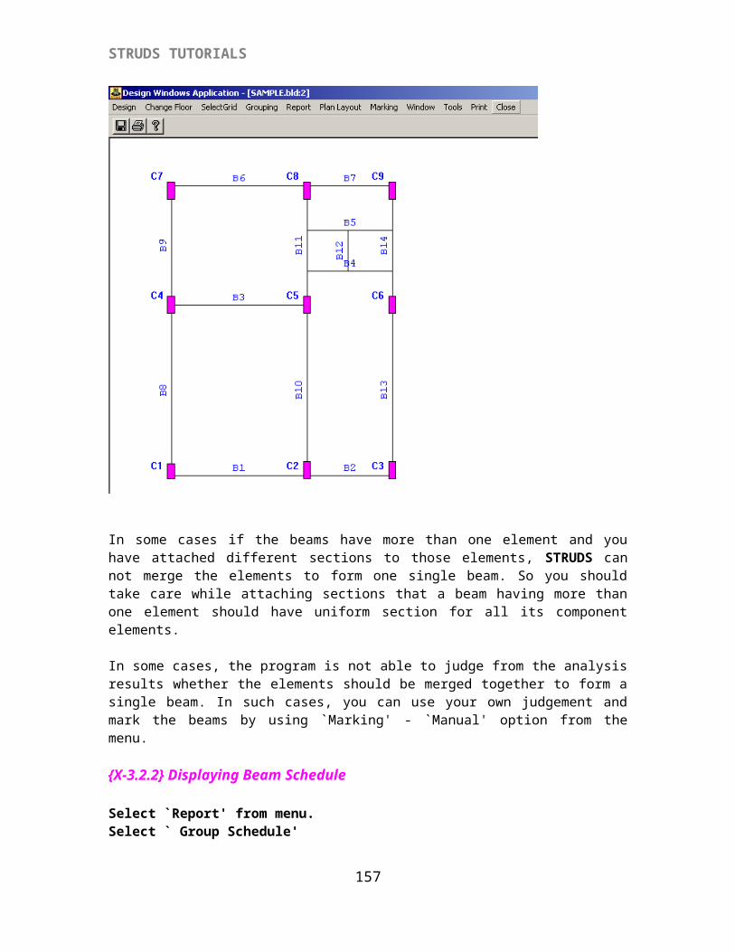
STRUDS TUTORIALS
Select `Close' option from menu bar.
{X-3.4.4} Displaying Footing Schedule
Select `Report' from menu.Select `Schedule' option.STRUDS displays the footing design schedule for all the footings.
157
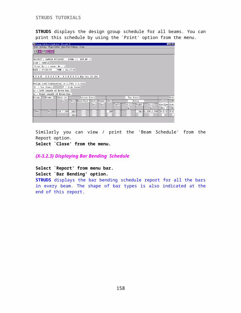
STRUDS TUTORIALS
You can get a print out of this schedule by using the `Print' option from menu. You can also see the print preview of this report by using options `Print' - `Preview' from the menu.Select `Close' from the menu bar.
{X-3.4.5} Displaying Footing Quantity Report
Select `Report' from the menu.Select `Quantity' option.STRUDS displays the quantity report for all the footings.
Select `Close'
{X-3.4.6} Displaying Centerline Plan Of Footings
Select `CenterLine' from menuSelect `Draw CenterLine' option.STRUDS displays the foundation plan of all the footings showing centers of footings, pit sizes, footing sizes and reinforcement provided in every footing.
158
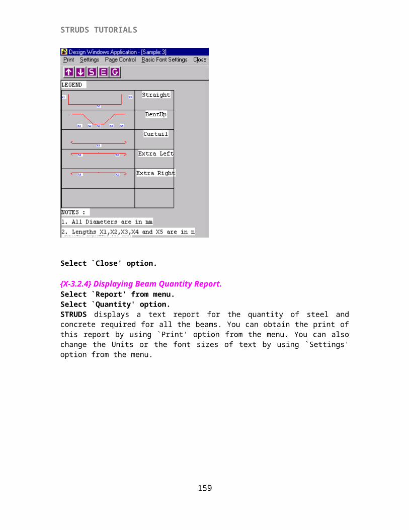
STRUDS TUTORIALS
You can put on/off the display in this graphics screen as -
Select `CenterLine' from the menu.Select `Display Settings' option.All the display settings by default are put on. You can put off say footing bars in X direction by clicking on that option. When you again click on the same option, the display is put on.Similarly you can use the options `CenterLine' - `Font Settings' to change the font sizes and font types of the text shown on the screen.
Select `Close' to come out of the footing design module. This way you have designed slabs, beams, columns and footings of the sample building by Plane Grid method.
159
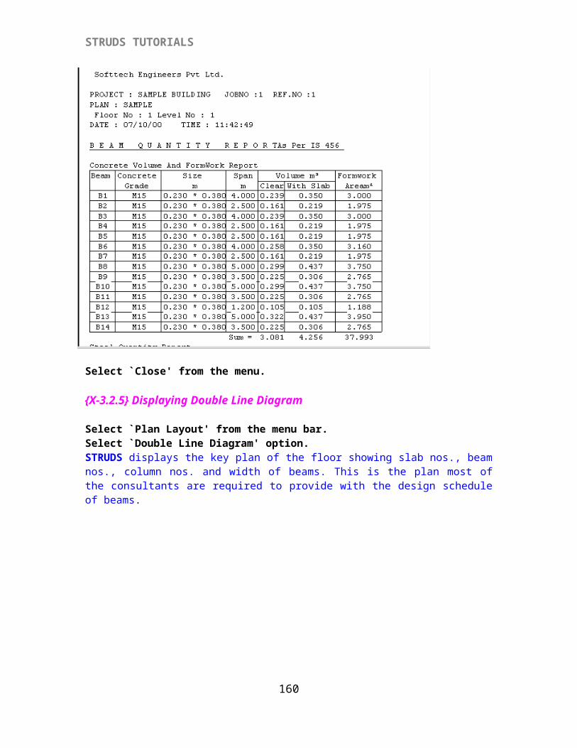
STRUDS TUTORIALS
PLANE FRAME METHOD
In this method, STRUDS automatically generates the plane frames in X and Y directions. The slab loads on beams and loads from secondary beams to primary beams are automatically computed by STRUDS.
{X-A 1} PREPROCESSOR
Go to the control menu of STRUDS.Select `Preprocessor' from menu. Select `Building' - `Open' option.Select the building 'Sample' from the window box.Select `Open' button.The building plan of this building appears on the screen.
You are now working on the Sample building project. For plane frames generation, it is essential that you must have analyzed all the floor grids in the building so that the secondary load values on primary beams are available to the program.
{X- A 1.1} Generating Plane Frames
Select `Plane Frame' from the menu.Select `Generate Grids' option.STRUDS now generates the gridlines for all the primary beams.
Select `Generate' option.STRUDS now generates the plane frames for all the primary beams.
Select `Load' from the menu.Select `Generate Sec. Loads' option.By using this option STRUDS generates the point loads from the secondary beams to primary beams by taking data from analysis results files of all the plane grids in the building.
{X-A 1.2} Generating Seismic and Wind Loads STRUDS can also automatically generate earthquake loads and wind loads on the frames as per the basic parameters provided by you.
Select `Setup' from menu.Select `Seismic Parameters' option.STRUDS displays a window box with many fields. You are required to fill in the values for basic parameters for seismic load consideration.
160
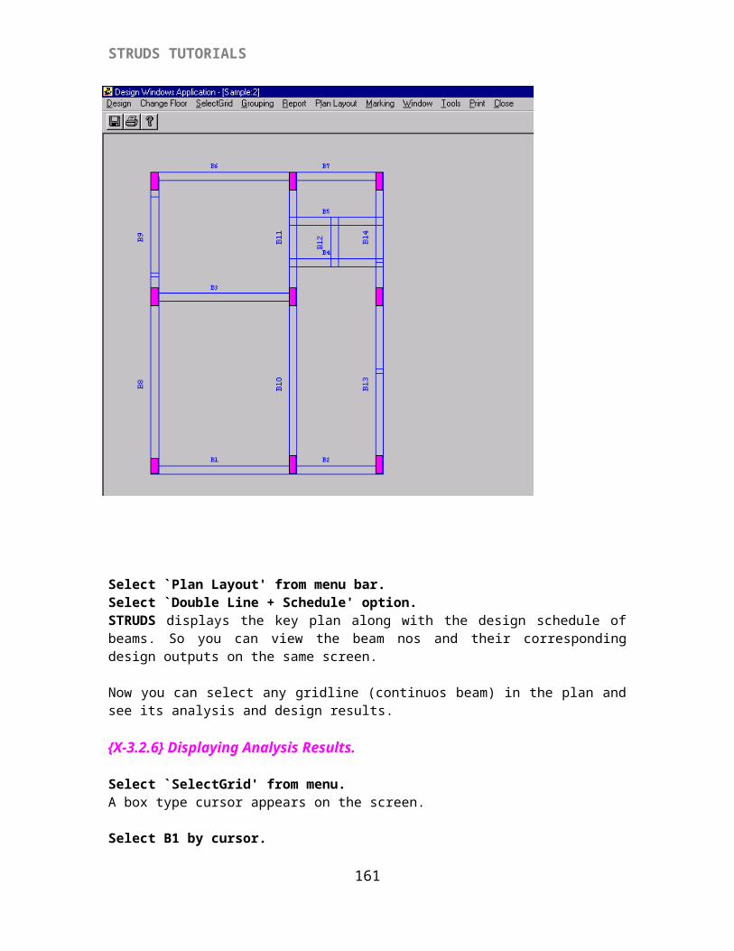
STRUDS TUTORIALS
Click `Help' button at the bottom left corner of the window. STRUDS shows a help file. You can click any of the options in the window. STRUDS displays the related pages from IS:1893 which you can read and provide input.
Select `File' - `Exit' to come out of the help topic.Select `Save' button.STRUDS gives message
Select `Yes' button.Select `Close' button from the window.Similarly you can generate the wind load on building.
Select `Setup' - `Wind Load Parameters' options from the menu.A window with fields appears on the screen. You can provide the basic parameters for wind load generation by providing values in the fields. STRUDS automatically calculates the value of K2. But you can change this value by clicking the `Change' button.
161
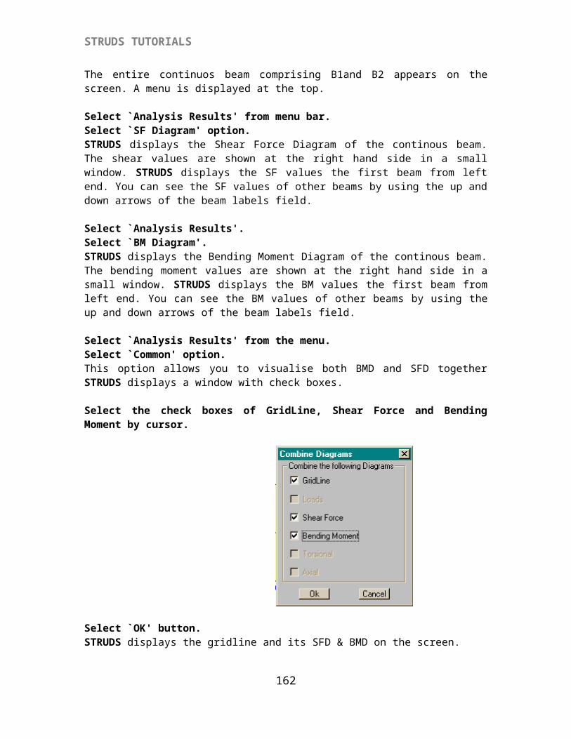
STRUDS TUTORIALS
Select `Save' button.Select `Close' button.
Select `Load' from menu bar.Select `Generate EQ Load' option.Select 'Frame stiffness Basis' option.
STRUDS calculates the earthquake load coming on the building in both X and Y directions and gives the message.
162
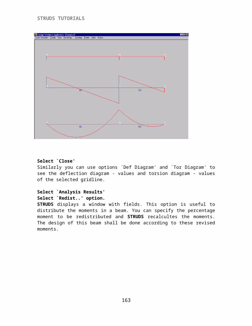
STRUDS TUTORIALS
Click 'OK'
Select `Load' from menu bar.Select `Generate Wind Load' option.STRUDS generates wind load acting on the building and gives the message.
Click 'OK'
{X-A 1.3} Viewing EQ and Wind Load Report
Select `Load' from menu bar.Select `EQ Load Report' option.STRUDS displays the calculations for the generation of earthquake load. Select `Print' - `Preview' options to see the entire text.
163
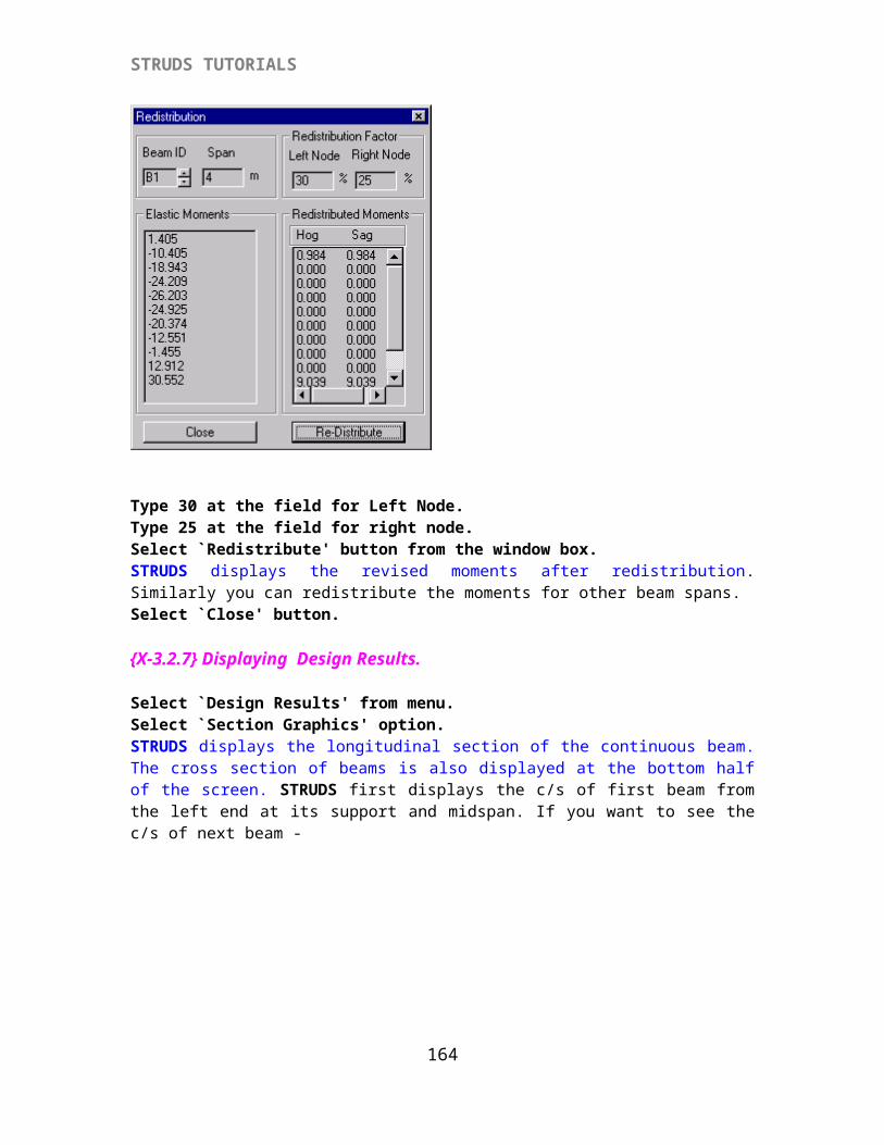
STRUDS TUTORIALS
Select `Close'Select `Close'
Select `Load' Select `Wind Load Report' option.STRUDS displays the intermediate results for wind load generation and their distribution.
Select `Print' - `Preview' options to see the entire text.
Select `Close'Select `Close'
This way you have generated the Plane Frames and applied Seismic and Wind loads on them.
{X-A 1.4} Viewing Frames and Horizontal Loads
You can also view the generated Plane Frames by using following options.
Select `Plane Frame' -`View'
164
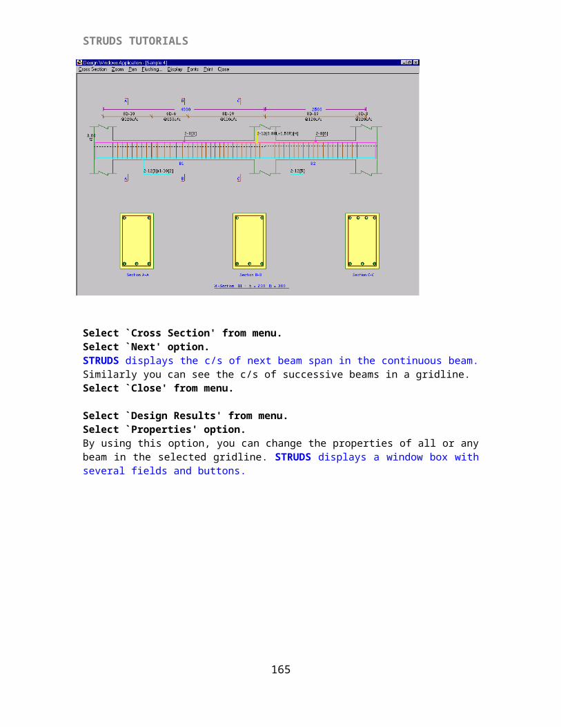
STRUDS TUTORIALS
STRUDS displays the building plan at the bottom most floor and a frame generated at the right half of the screen. In the plan the names of frames generated and their locations are shown.
Below the menu bar, at top left hand four icons are shown.
The first three icons are for display of plan and frame simultaneously or separately. The fourth icon is for selection of frame. When you click this icon, a cursor appears on the screen. You can click any of the grid lines and the frame formed along that grid is shown in the right half portion of screen.
Also at top center two pull down menus are available. In the left menu you can select the floor plan which is to be displayed. In the right hand menu you can select the frame which is to be displayed.
Select `Settings' from menu bar.Select `EQ Load' option.Select `+ve Y' option.STRUDS displays the value of seismic load in the form of nodal loads acting at every floor level. Note that for Horizontal frames the options `+ve Y' and `-ve Y' are inactivated. Similarly for vertical frames, the options `+ve X' and `-ve X' are inactivated. Because the seismic load in X
165
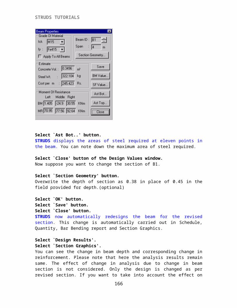
STRUDS TUTORIALS
directions is taken by horizontal frames and the seismic load in Y direction is taken by vertical frames.
Select the `Setting' from menu bar.Select `Base Shear' option.Select `+ve Y'
166
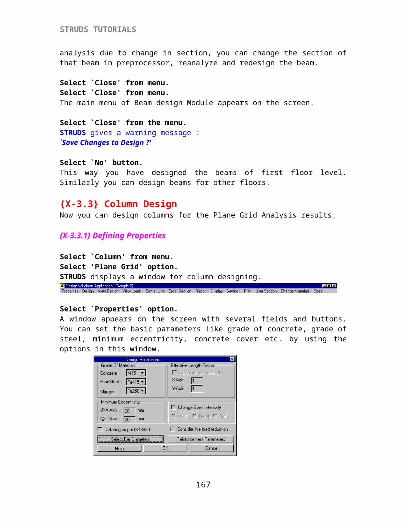
STRUDS TUTORIALS
In the Right hand half portion, STRUDS displays the graphical representation of Base Shear on the frame. Similarly you can select different frames and see the values of EQ load and base shear.
Select `Setting' from menu.Select `Wind Load' option.Select `+ve Y'STRUDS displays the nodal loads coming on different floor levels due to wind pressure. Similarly you can select different frames and see the wind loads on them.
Select `Close' from menu.
Select `Loadcases' from the menu.Select `Plane Frame'A window appears on the screen. This window displays a list of available loadcases.
You can select the loacases for which you can analyze the structure. By default, STRUDS analyses all structures for DL and LL. If you want to add more loadcases, you can do so by following procedure.
Select `WL X+' from list.Select `Select' button.Select `WL Y+'Select `Select' buttonSelect `EQL X+'Select `Select' button.Select `EQ Y+' Select `Select' buttonSelect `OK' button.Now STRUDS will analyze the plane frames for six load cases i. e. DL, LL, WLX+, WLY+, EQLX+, EQLY+. You can define any load combinations of these load cases. And select the load combination for which the design to be done. Or STRUDS will design the structure for worst load combination automatically.
Select `Plane Frame' from menu bar.
167
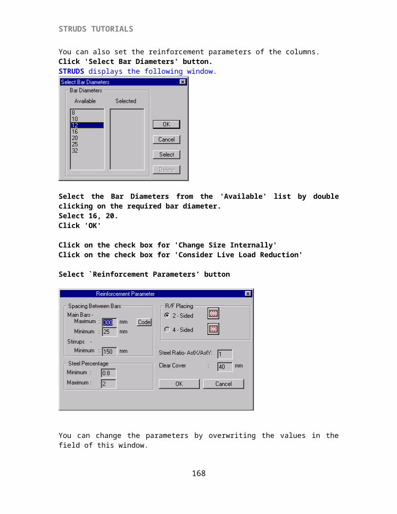
STRUDS TUTORIALS
Select `Analysis Files' - `All' options from the pull down menu.STRUDS displays a window where you can specify the location where the *.ctl file is to be saved. It should be noted that the files of plane frame should be saved only after defining the load combinations. If you first save the files and then define load cases, the frames shall be analyzed for default load cases of Dead Load and Live Load only.Select `Save' button from the window.Select `Building' - `Close' option.STRUDS gives a warning message.
Select `Yes' button.Select `Building' -`Exit' options.The Control Menu of STRUDS appears on screen.
{X-A 2} Analysis of Plane Frames
Select `Analysis' from control menu bar.Select `Open' - `Building file' option.STRUDS displays a window where you can locate the *ctl file for analysis of the building.
Select `Sample.ctl' fileSelect `Open' button.Select `Analysis' from menu.Select `Plane Frames'STRUDS displays a window with the list of available files for analysis. For every frame, a separate file is created. You can also do selective analysis by selecting one particular file.
Select `Add All' button.Select `OK' button.STRUDS analyses all the plane frames for all the defined load cases.
Select `OK' button from the message box.Now you can see the analysis results by selecting `PostProcessor' from menu bar. Or you can directly go for designing of the structure.
168
STRUDS TUTORIALS
{X-A 3} DESIGN BY PLANE FRAME METHOD
Select ` Design' from the menu.Select `File' - `Open' options.Select file `Sample.bld' from the window.Select `OK' button.The floor plan of the bottom most level of Sample building appears on the screen.
The Slab Design will be same as that of Plane Grid Method.
In case of beams, they will be designed for every frame.
{X-A3.1} Creating New Load Combinations
You can specify the load combinations for which the beams are to be designed. Select `Load Combination' from menu bar.Select 'Beam' option.STRUDS displays a window with the list of defined load cases at the left.
Select `New' button.(optional)Select `DL' from the list.Write 1.1 in the field provided for the field of DL below the list.Select `Add' button.Select `LL' from listWrite `1.1' in the field.Select `Add' button.Select `WLX+' from the list.Write `1.1' in the field.Select `Add' button.Select `Close' button.This way you have specified a load combination of 1.1DL + 1.1 LL + 1.1 WLX+
169
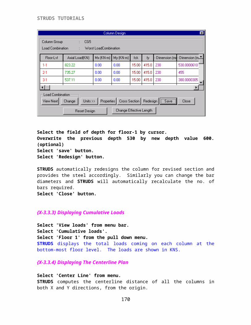
STRUDS TUTORIALS
Similarly you can create any other load combinations as desired by you. STRUDS can design the structure for any of the load combination or the worst load combination.
Select `Close' button.
{X-A3.2} Beam Design
Select `Beam' from menu.Select `Settings' from menu.STRUDS displays a window box with several fields and buttons. You can use the options in this window to specify the basic parameters for beam design.
Select `Reinforcement' button.STRUDS displays another window to specify the reinforcement parameters. You can again change these parameters as per your discretion.
Select 'Stirrup Grade': Fe250Select 'Stirrup Dia' : 6 mmSelect `OK' button.
Select `Beam' from menu
170
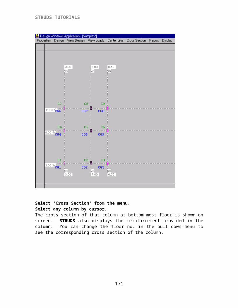
STRUDS TUTORIALS
Select `Plane Frame' option.
STRUDS displays the floor plan and the frames on the screen.
Select the fourth icon at top left corner below menu bar.A box cursor appears on the screen.
Select any of the frames by moving cursor along any grid line in the floor plan. That frame is displayed in the right half portion.
171
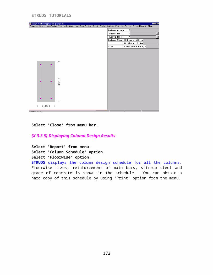
STRUDS TUTORIALS
Select `Proceed To design' from menu bar.You enter into the Beam Design Module of STRUDS. The selected frame is displayed on the screen.
Select `Design' from menu.Select `New'STRUDS displays a window showing all the load combinations specified by you in addition to the worst load combination.
Select `Worst Load Combination' from the list.STRUDS designs all the beams in this frame for the worst load combination.
{X-A3.3} Displaying Beam Schedule
Select `Report' from the menu.Select `Schedule' option.STRUDS displays a text report of the design schedule of all the beams. You can print this report by using `Print' option from the menu. You can also change the fonts etc. of the text by using `Setting' option from the menu.Select `Close'
{X-A3.4} Displaying Bar Bending Schedule.
Select `Report' from menu bar.Select `Bar Bending' option.STRUDS displays the bar bending schedule report for all the bars in every beam. The shape of bar types is also indicated at the end of this report.Select `Close' option.
{X-A3.5} Displaying Beam Quantity Report.
Select `Report' from menu.Select `Quantity' option.STRUDS displays a text report for the quantity of steel and concrete required for all the beams. You can obtain the print of this report by using `Print' option from the menu. You can also change the Units or the font sizes of text by using `Settings' option from the menu.Select `Close' from the menu.
172
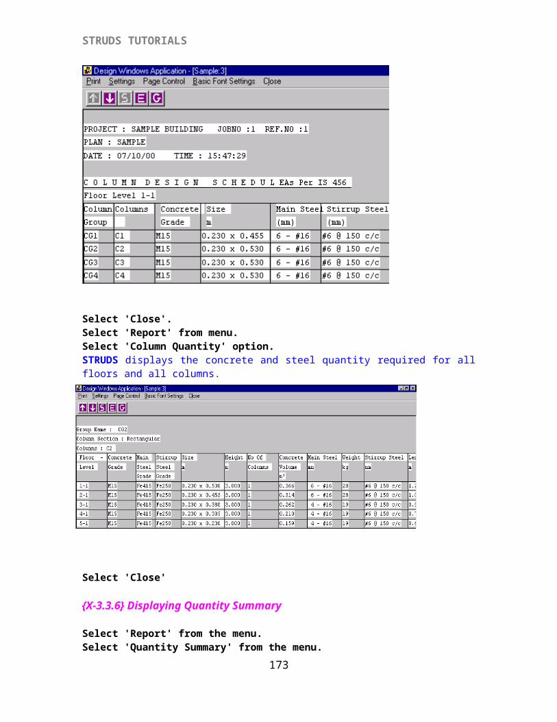
STRUDS TUTORIALS
{X-A3.6} Displaying Analysis Results.Select `SelectGrid' from menu.A box type cursor appears on the screen.
Select B1 by cursor.The entire continuos beam comprising B1, B2 appears on the screen. A menu is displayed at the top.
Select `Analysis Results' from menu bar.Select `SF Diagram' option.STRUDS displays the Shear Force Diagram of the continuous beam. The shear values are shown at the right hand side in a small window. STRUDS displays the SF values the first beam from left end. You can see the SF values of other beams by using the up and down arrows of the beam labels field.
Select `Analysis Results'.Select `BM Diagram'. STRUDS displays the Bending Moment Diagram of the continuous beam. The bending moment values are shown at the right hand side in a small window. STRUDS displays the BM values of the first beam from left end. You can see the BM values of other beams by using the up and down arrows of the beam labels field.
Select `Analysis Results' from the menu.Select `Common' option. This option allows you to visualize both BMD and SFD together. STRUDS displays a window with check boxes.
Select the check boxes of GridLine, Shear Force and Bending Moment by cursor.Select `OK' button.STRUDS displays the gridline and its SFD & BMD on the screen.
Select `Close'Similarly you can use options `Def Diagram' and `Tor Diagram' to see the deflection diagram - values and torsion diagram - values of the selected gridline.
Select `Analysis Results'Select `Redist..' option.STRUDS displays a window with fields. This option is useful to distribute the moments in a beam. You can specify the percentage moment to be redistributed and STRUDS recalculates the moments. The design of this beam shall be done according to these revised moments.
Type 30 at the field for Left Node.Type 25 at the field for right node.Select `Redistribute' button from the window box.STRUDS displays the revised moments after redistribution. Similarly you can redistribute the moments for other beam spans.Select `Close' button.
173
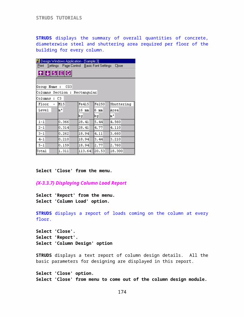
STRUDS TUTORIALS
{X-A3.7} Displaying Beam Design Results.
Select `Design Results' from menu.Select `Section Graphics' option.STRUDS displays the longitudinal section of the continuous beam. The cross section of beams is also displayed at the bottom half of the screen. STRUDS first displays the c/s of first beam from the left end at its support and mid-span. If you want to see the c/s of next beam -
Select `Cross Section' from menu.Select `Next' option.STRUDS displays the c/s of next beam span in the continuous beam. Similarly you can see the c/s of successive beams in a gridline.Select `Close' from menu.
Select `Design Results' from menu.Select `Properties' option.By using this option, you can change the properties of all or any beam in the selected gridline. STRUDS displays a window box with several fields and buttons.
Select `Ast Bot..' button.STRUDS displays the areas of steel required at eleven points in the beam. You can note down the maximum area of steel required.
Select `Close' button from the Design Values window.Now suppose you want to change the section of B1.
Select `Section Geometry' button.Overwrite the depth of section as 0.38 in place of 0.45 in the field provided for depth.(optional)
174
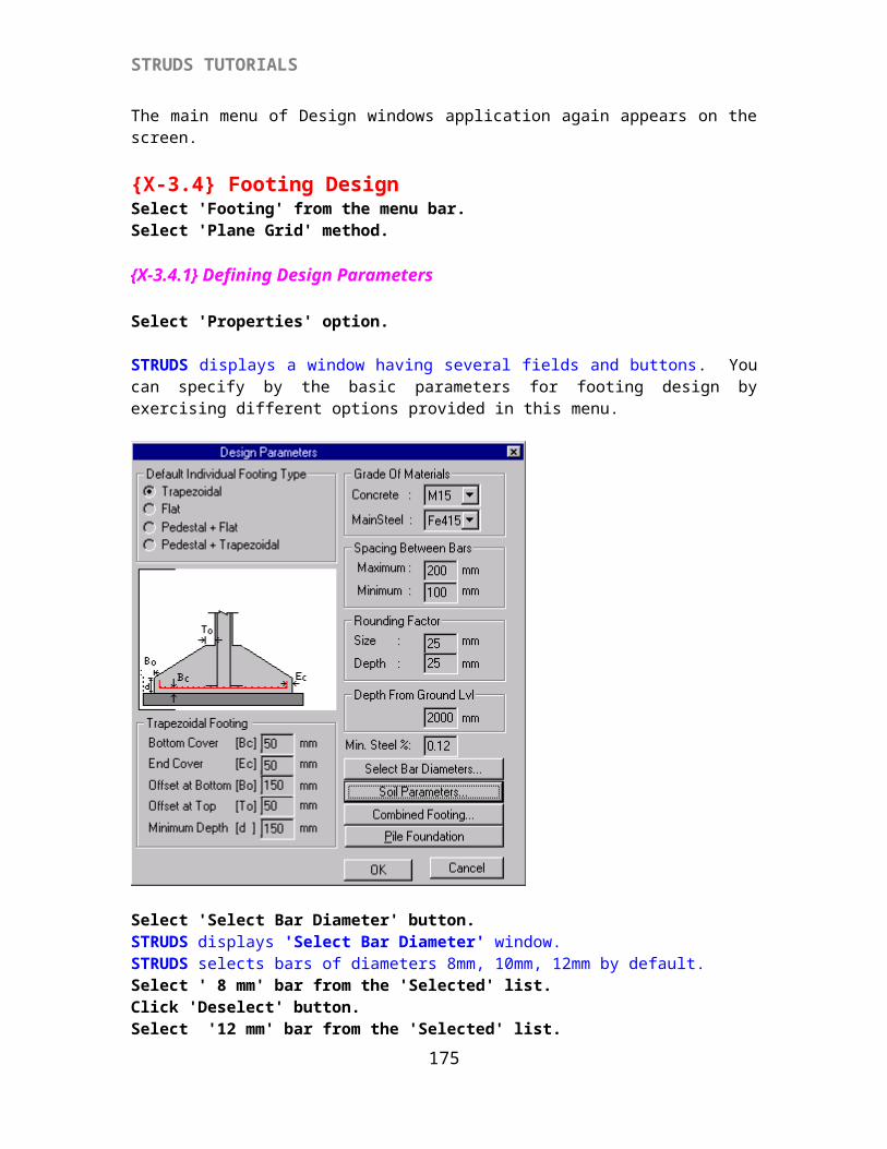
STRUDS TUTORIALS
Select `OK' button.Select `Save' button.Select `Close' button.STRUDS now automatically redesigns the beam for the revised section. This change is automatically carried out in Schedule, Quantity, Bar Bending report and Section Graphics.
Select `Design Results'.Select `Section Graphics'.You can see the change in beam depth and corresponding change in reinforcement.
Please note that here the analysis results remain same. The effect of change in analysis due to change in beam section is not considered. Only the design is changed as per revised section. If you want to take into account the effect on analysis due to change in section, you can change the section of that beam in preprocessor, reanalyze and redesign the beam.
Select `Close' from menu.Select `Close' from menu.The main menu of Beam design Module appears on the screen.
Select `Close' from the menu.STRUDS gives a warning message :`Save Changes to design ?'Select `No' button.This way you have designed the beams of selected plane frame.Similarly you can design beams for other frames.
{X-A 3.8} Column Design
Select `Column’ from Design Windows Application menu bar.The options `Orientation’ and `Grouping’ are the same as used in `Column’ menu of the Preprocessor.
{X-A 3.9} Column NumberingSelect `Numbering’ option.This option allows you to provide the numbers to columns in the sequence specified by you. STRUDS displays a window which allows you to number the columns in four different ways. You can select any of the icon to select your numbering system.
Select `close’ button from the window.Select `Column’ - `Plane Frames’ option.
175
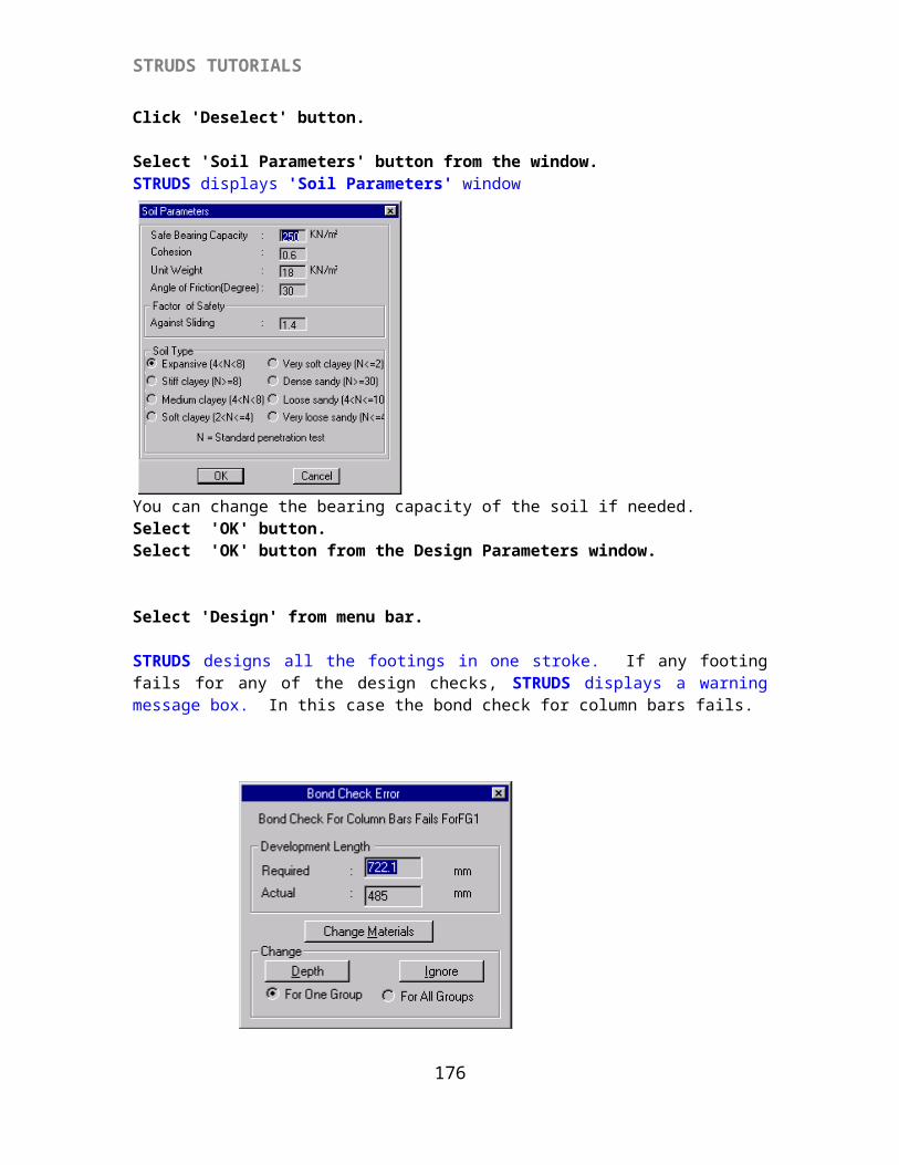
STRUDS TUTORIALS
STRUDS reads all the reaction files from the analysis of all plane frames. The floor plan of bottom-most floor is displayed on the screen.
{X-A 3.10} Defining Column Design Parameters
Select 'Properties' from the menu.A window appears on the screen with several fields and buttons. You can set the basic parameters like grade of concrete, grade of steel, minimum eccentricity, concrete cover etc. by using the options in this window.
You can also set the reinforcement parameters of the columns.Click 'Select Bar Diameters' button.STRUDS displays the following window.
Select the Bar Diameters from the 'Available' list by double clicking on the required bar diameter.Select 16, 20.Click 'OK'Click on the check box for 'Change Size Internally'Click on the check box for 'Consider Live Load Reduction'
Select `Reinforcement Parameters’ button
176
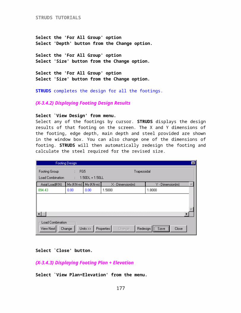
STRUDS TUTORIALS
You can change the parameters by overwriting the values in the field of this window.
Select `OK' button.
Select `Design’ from the menu.Select `New’ - `Biaxial’ options.STRUDS starts design of all the columns for all defined load combinations. The final design is for the worst load combination out of the defined load combinations. If any column fails for any check, STRUDS displays a warning message.
Select the check box for`Change bar combination’ option.Key in 2 in the check box for N1 and Key in 16 in the check box for D1.Select `Redesign’ option.STRUDS redesigns the column. And displays the same message box again. This is because it is designing each column at every floor so you have to change the bar combination whenever required..
177
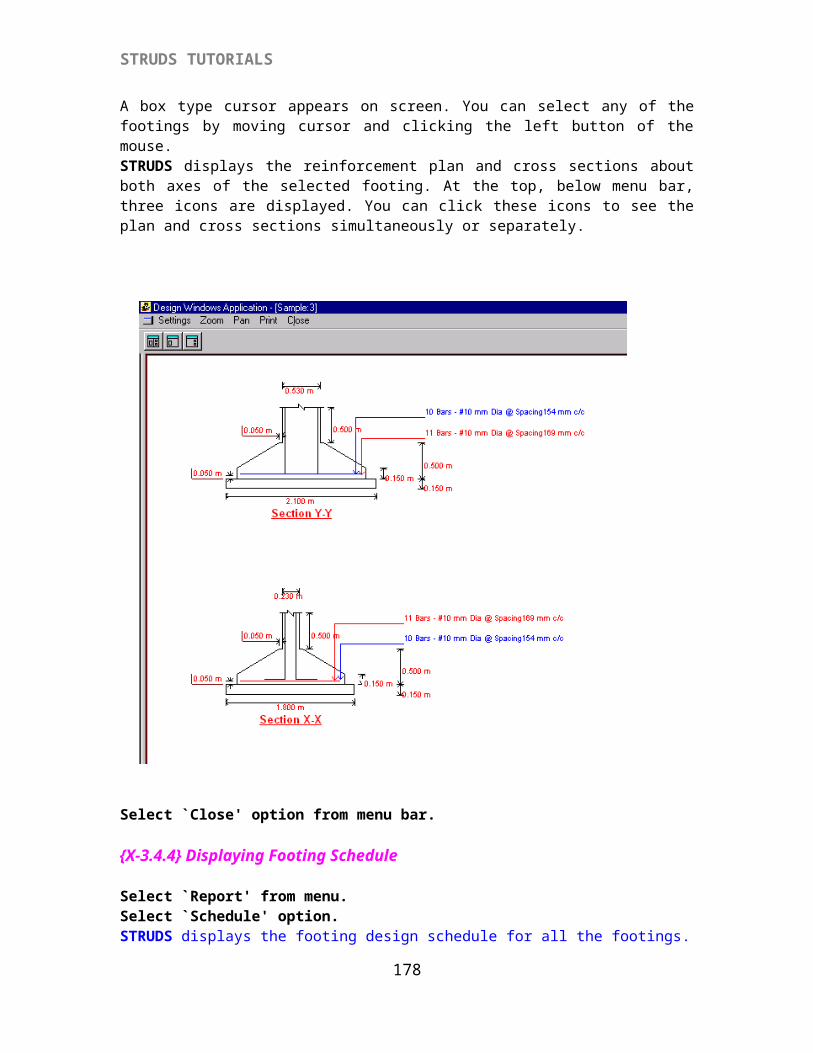
STRUDS TUTORIALS
ORSelect `Ignore’ button. (optional)Similarly you can select `Ignore’ when ever the check for bar spacing is not satisfied and you can increase the column size when the maximum steel percentage exceeds the limit.
{X-A 3.11} Saving Column Design
Select `Design’ from the menu.Select 'Save' option.
{X-A3.12} Displaying Column Design
Select `View design’ from menu.Select any column by cursor.STRUDS displays the design details of the selected column in a window box. All the parameters like axial load, moments about X and Y axes, size of the column, reinforcement area provided, bars & their numbers etc. are shown. If you want to change the size of column at any floor, you can do so by just overwriting the previous width and depth. Then you can select `Save’ and `Redesign’ buttons to allow the program redesign the column. Please note that here the P, Mx and My remain same. Only the effect of change in size in design is taken care of.
Select `Close’ button.
{X-A 3.13} Displaying Loads On Column
Select `View Loads’ from menu.Select `Cumulative Loads’ option.By using this option you can see the cumulative loads coming on all columns at any floor. STRUDS displays a window box and a pull down menu providing the numbers of all floors.
Select the floor no. 1 from the menu.Select `OK’ button.STRUDS displays on screen the cumulative loads on all the columns. The loads are displayed in kNs.
Select `View Loads’ from menu.Select `Select Column’ option.Select any column by cursor.STRUDS displays the floor-wise axial loads and moments about X and Y for the selected column.
Select `Close’ button.
{X-A 3.14} Displaying Centerline Plan
Select 'Center Line' from menu.STRUDS computes the centerline distance of all the columns in both X and Y directions, from the origin.
178
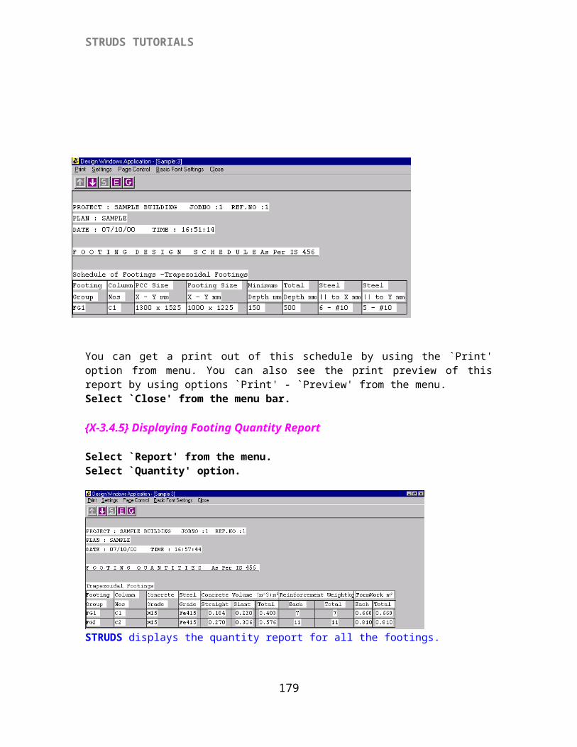
STRUDS TUTORIALS
{X-A 3.15} Displaying Column Cross Section
Select 'Cross Section' from the menu.Select any column by cursor.The cross section of that column at bottom most floor is shown on screen. STRUDS also displays the reinforcement provided in the column. You can change the floor no. in the pull down menu to see the corresponding cross section of the column.Select 'Close' from menu bar.
{X-A 3.16} Displaying Column Schedule
Select 'Report' from menu.Select 'Column Schedule' option.
STRUDS displays the column design schedule for all the columns. Floor-wise sizes, reinforcement of main bars, stirrup steel and grade of concrete is shown in the schedule. You can obtain a hard copy of this schedule by using 'Print' option from the menu.Select 'Close'.
{X-A 3.17} Displaying Column Quantity Report
Select 'Report' from menu.Select 'Column Quantity' option.STRUDS displays the concrete and steel quantity required for all floors and all columns.Select 'Close'
Select 'Report' from the menu.Select 'Quantity Summary' from the menu.STRUDS displays the summary of overall quantities of concrete, diameter-wise steel and shuttering area required per floor of the building for every column.Select 'Close' from the menu.
{X-A 3.18} Displaying Column Load Report.
Select 'Report' from the menu.Select 'Column Load' option.STRUDS displays a report of loads coming on the column at every floor.Select 'Close'.
{X-A 3.19} Displaying Detail Column Design Report.
Select 'Report' from the menu.Select 'Column Design' optionSTRUDS displays a text report of column design details. All the basic parameters for designing are displayed in this report.
179
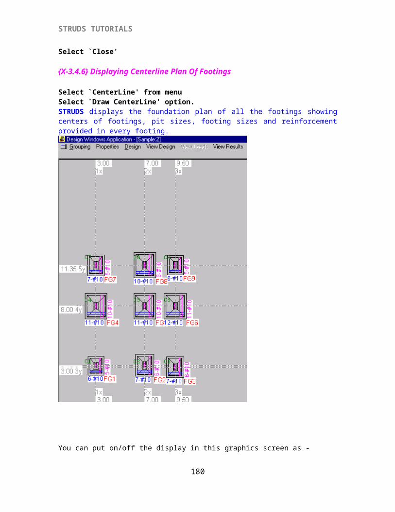
STRUDS TUTORIALS
{X-A 3.20} Displaying Column Schedule Report.
Select `Report’Select `Schedule’ option.Select `Worst Load Combination’ option.STRUDS displays a text report of the floor-wise worst load combination for every column. A table is displayed for floor -wise design output and the load cases with factors for the worst load combination in the last column of the table.Select `Close’ from menu.
Select `Report’ from menu.Select `All load combinations’ option.STRUDS displays the design results of all columns for all load combinations in text form.
Select `Close’ option.Select 'Close' from menu to come out of the column design module.
The main menu of Design windows application again appears on the screen.
{X-A3.21}Footing Design
Select `Footing’ Select ‘Plane frame’ option.The main menu of Footing Design module appears on the screen. STRUDS displays the floor plan of the bottom most floor.
Select ‘Grouping’ option to group the footings as per the loads and the type of footings (optional).Select 'Properties' option.
{X-A3.22} Defining Design Parameters
STRUDS displays a window having several fields and buttons. You can specify by the basic parameters for footing design by exercising different options provided in this menu.
180
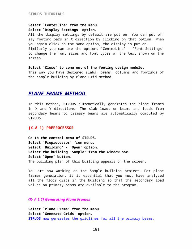
STRUDS TUTORIALS
Select 'Select Bar Diameter' button.STRUDS displays 'Select Bar Diameter' window.STRUDS selects bars of diameters 8mm, 10mm, 12mm by default.Select 8 mm bar from the 'Selected' list.Click 'Deselect' button.Select 12 mm bar from the 'Selected' list.Click 'Deselect' button.
Select 'Soil Parameters' button from the window. STRUDS displays a small window where you can specify the properties of soil.Select 'OK' button.Select 'OK' button from the Design Parameters window.
Select 'Design' from menu bar.
STRUDS designs all the footings in one stroke. If any footing fails for any of the design checks, STRUDS displays a warning message box. In this case the bond check for footing bars fails.
181
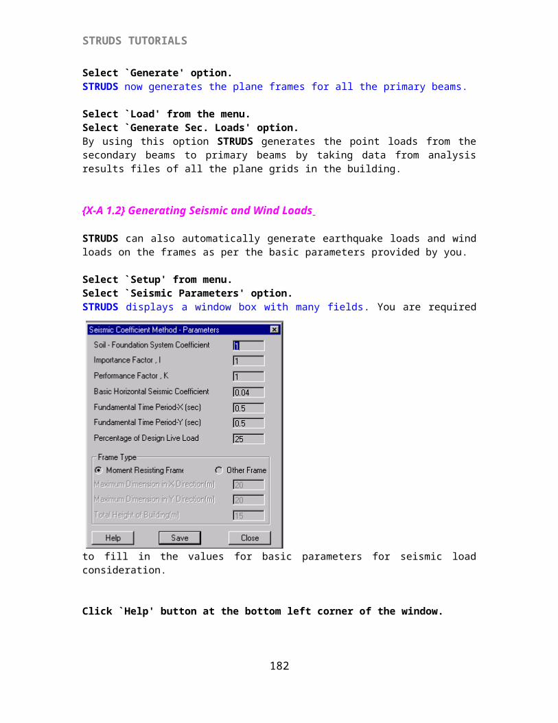
STRUDS TUTORIALS
Select the 'For All Group' optionSelect 'Depth' button from the Change option.
Select the 'For All Group' optionSelect 'Size' button from the Change option.
Select the 'For All Group' optionSelect 'Size' button from the Change option.
STRUDS completes the design for all the footings.Select 'Design' from menu bar.Select 'Save' option.
{X-A3.23} To View Design
Select `View Design' from menu.Select any of the footings by cursor. STRUDS displays the design results of that footing on the screen. The X and Y dimensions of the footing, edge depth, main depth and steel provided are shown in the window box. You can also change one of the dimensions of footing. STRUDS will then automatically redesign the footing and calculate the steel required for the revised size.Select `Close' button.
{X-A3.24} To View Plan + Elevation.
Select `View Plan+Elevation' from the menu.A box type cursor appears on screen. You can select any of the footings by moving cursor and clicking the left button of the mouse.
STRUDS displays the reinforcement plan and cross sections about both axes of the selected footing. At the top, below menu bar, three icons are displayed. You can click these icons to see the plan and cross sections simultaneously or separately.Select `Close' option from menu bar.
{X-A3.25} To View Footing ScheduleSelect `Report' from menu.
182
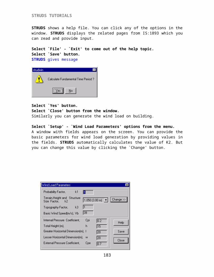
STRUDS TUTORIALS
Select `Schedule' option.STRUDS displays the footing design schedule for all the footings.You can get a print out of this schedule by using the `Print' option from menu. You can also see the print preview of this report by using options `Print' - `Preview' from the menu.Select `Close' from the menu bar.
{X-A3.26} To View Quantity ReportSelect `Report' from the menu.Select `Quantity' option.STRUDS displays the quantity report for all the footings.Select `Close'
{X-A3.27} To View Footing CenterLine PlanSelect `CenterLine' from menuSelect `Draw CenterLine' option.STRUDS displays the foundation plan of all the footings showing centers of footings, pit sizes, footing sizes and reinforcement provided in every footing. You can put on/off the display in this graphics screen as -
Select `CenterLine' from the menu.Select `Display Settings' option.All the display settings by default are put on. You can put off say footing bars in X direction by clicking on that option. When you again click on the same option, the display is put on.Similarly you can use the options `CenterLine' - `Font Settings' to change the font sizes and font types of the text shown on the screen.
Select `Close' to come out of the footing design module. This way you have designed beams, columns and footings of the sample building by Plane Frame method.
183
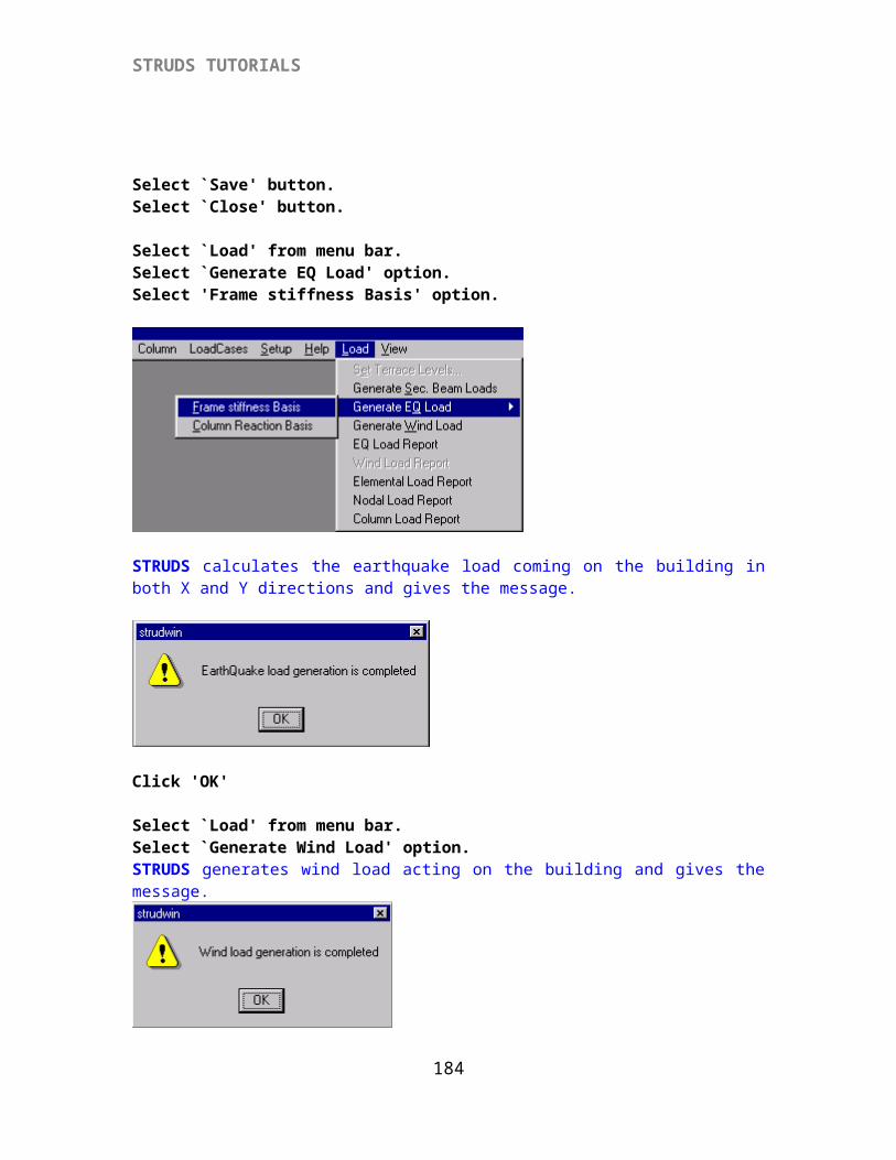
STRUDS TUTORIALS
SPACE FRAME METHOD
{X-B1} PREPROCESSOR
This is the most desirable method for analysis and design. STRUDS automatically generates a 3-d space frame from the floor plans defined by you. You can also generate Wind and Earthquake loads as in Plane Frame Method.
Go to the control menu of STRUDS.Select `Preprocessor' from menu. Select `Building' - `Open' option.Select the building ‘Sample’ from the window box.Select `Open' button.You are now working on the Sample building project.
{X-B 1.1} Generating Space Frame
Select `Space Frame’ from the menu.Select `Generate’ option.STRUDS generates the space frame for Sample building. You can change the support conditions at the bottom of space frame i.e. at footing level by using `Space Frame’ - `Support’ option. By default the support condition is taken as fixed. So the footings will be designed for biaxial moments.
{X-B 1.2} To View Space Frame
Select `Space Frame’ from menu.Select `View’ -`Space Frame’ option.By using this option you can view the space frame generated for the sample building. STRUDS displays a new screen with graphical icons at the top left corner and along the left side of the screen.
At the top two pull down menu are available which show the floor no. and level no. of each floor.
Select `All Floors’ from the pull down menu. Select the icon for `Isom’ (Isometric view) from the left top corner.STRUDS displays the 3-d view of space frame for the entire structure. Similarly you can select a particular floor and see the 3-d view of that floor.
184
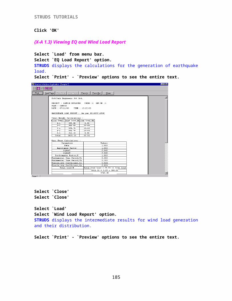
STRUDS TUTORIALS
Select the icon for `X-Y’ (View in XY plane)STRUDS displays the 2-d plane grid view of space frame in XY plane. Select `X-Z’ icon.STRUDS displays the 2-d view in XZ plane. Which is the plane frame.Select `Y-Z’ icon.STRUDS displays the view of the space frame in YZ plane.Which is a plane frame.
Four icons are displayed in the form of left / right / up and down arrows. You can select these icons to move the display of structure to left, right, up or down.There are two icons shown by + and - sign. These icons indicate Zoom-in and Zoom-out option. You can select these icons to enlarge or compress the view of structure.Below this another pair of icons is present. The left icon is for Zoom-all option. The right icon is for Zoom-Window option. You can select these icons to view the full structure or enlarge the selected portion of structure.You can also rotate the 3-d space frame by using the Rotation option. At the top left corner, four icons are arranged horizontally.
Select the second icon.STRUDS displays two different views of the structure in horizontally split manner.
Select the third icon.STRUDS displays two different views of the structure in vertically split manner.
Select the fourth icon.STRUDS displays four different views of the structure.
185
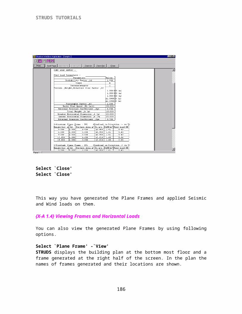
STRUDS TUTORIALS
Select the first icon.STRUDS displays the full screen view of the structure.
Select `Space Frame’ from menu.Select `View’ - `Settings’STRUDS displays a window with two pull down menus.
Select the left pull down menu Element Ids.Select `Space Frame’ option.Select `Node Ids’ menu. Select `Space Frame’ option.Select `OK’ button.
STRUDS displays the element nos. and node nos. of all the elements and nodes of the structure in display.Select `Building’ from menu.Select `Close’ option.STRUDS puts off the display of space frame view.
{X-B 1.3} Generating Seismic and Wind Loads Select `Setup' from menu.Select `Seismic Parameters' option.
186
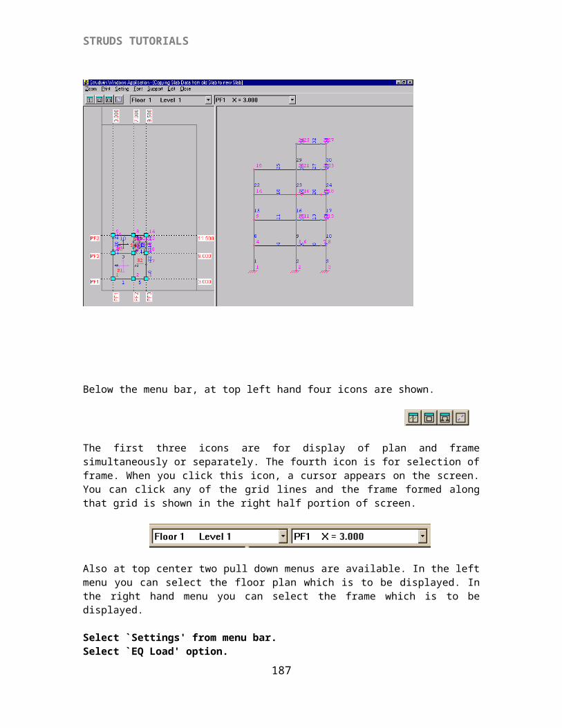
STRUDS TUTORIALS
STRUDS displays a window box with many fields.
You are required to fill in the values for basic parameters for seismic load consideration. STRUDS generates loads as per IS:1893. If you do not know about the values to be fed in -
Click `Help' button at the bottom left corner of the window. STRUDS shows a help file. You can click any of the options in the window. STRUDS displays the related pages from IS:1893 which you can read and provide input.
Select `File' - `Exit' to come out of the help topic.Select `Save' button.STRUDS gives message
Select `Yes' button.Select `Close' button from the window.Similarly you can generate the wind load on building.
Select `Setup' - `Wind Load Parameters' options from the menu.A window with fields appears on the screen. You can provide the basic parameters for wind load generation by providing values in the fields. STRUDS automatically calculates the value of K2. But you can change this value by clicking the `Change' button.
187
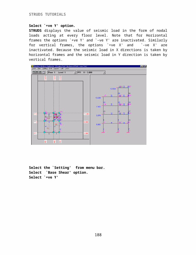
STRUDS TUTORIALS
Select `Save' button.Select `Close' button.
Select `Load' from menu bar.Select `Generate EQ Load' option.STRUDS calculates the earthquake load coming on the building in both X and Y directions.
Select `Load' from menu bar.Select `Generate EQ Load' option.Select 'Frame stiffness Basis' option.
STRUDS calculates the earthquake load coming on the building in both X and Y directions and gives the message.
188
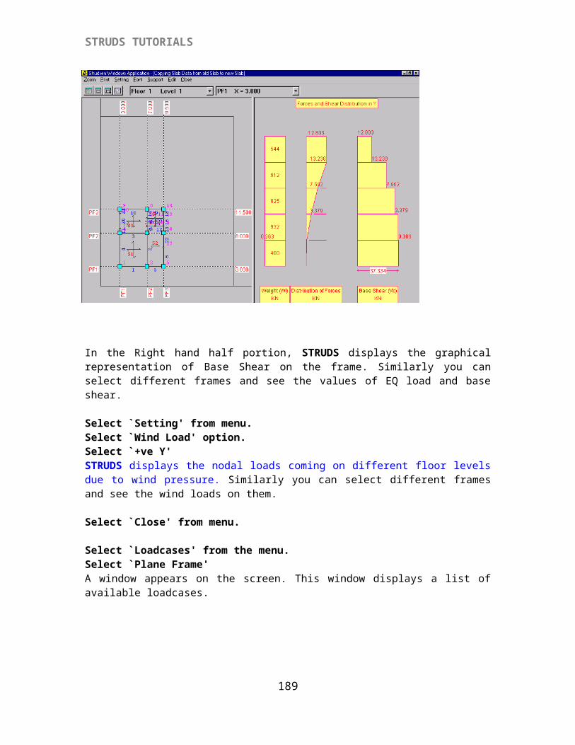
STRUDS TUTORIALS
Click 'OK'
Select `Load' from menu bar.Select `Generate Wind Load' option.STRUDS generates wind load acting on the building and gives the message.
Click 'OK'
Select `Load' from menu bar.Select `EQ Load Report' option.STRUDS displays the calculations for the generation of earthquake load. Select `Print' - `Preview' options to see the entire text.Select `Close'
Select `Load' Select `Wind Load Report' option.STRUDS displays the intermediate calculations for wind load generation and their distribution.Select `Close' option.
{X-B 1.4} Defining Load Cases
Select `Loadcases' from the menu.Select `Space Frame'A window appears on the screen. This window displays a list of available loadcases. You can select the loacases for which you can analyze the structure. By default, STRUDS analyses all structures for DL and LL. If you want to add more loadcases, you can do so by following procedure.
Select `WL X+' from list.Select `Select' button.Select `WL Y+'Select `Select' buttonSelect `EQL X+'Select `Select' button.Select `EQ Y+' Select `Select' buttonSelect `OK' button.Now STRUDS will analyze the space frame for six loadcases i. e. DL, LL, WLX+, WLY+, EQLX+, EQLY+. You can define any load combinations of these load cases. And select the load case for which the design to be done. Or STRUDS will design the structure for worst load combination automatically.
Select `Space Frame' from menu bar.Select `Analysis Files' - `All' options from the pull down menu.
189
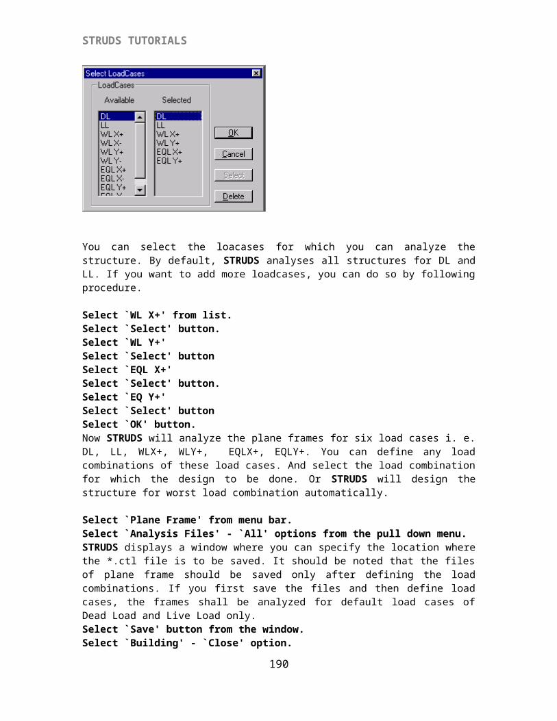
STRUDS TUTORIALS
STRUDS displays a window where you can specify the location where the *.ctl file is to be saved.
Select `Save' button from the window.Select `Building' - `Close' option.STRUDS gives a warning message.
Select `Yes' button.Select `Building' -`Exit' options.The Control Menu of STRUDS appears on screen.
{X-B 2} Analysis of Space Frame
Select `Analysis' from menu bar.Select `Open' - `Building file' option.STRUDS displays a window where you can locate the *ctl file for analysis of the building.
Select `Sample.ctl' fileSelect `Open' button.Select `Analysis' from menu.Select `Space Frame'STRUDS analyses the space frame for all the defined loadcases.
Select `OK' button from the message box.Now you can see the analysis results by selecting `PostProcessor' from menu bar. Or you can directly go for designing of the structure.
{X-B 3} DESIGN BY SPACE FRAME METHOD
Select ` Design' from the control menu.Select `File' - `Open' options.Select file `Sample.bld' from the window.Select `OK' button.The floor plan of the bottom most level of Sample building appears on the screen.
The Slab Design will be same as that of Plane Grid Method.
In case of beams, they will be designed for entire space frame. But their results will be displayed floor wise as in Plane Grid method.
{X-B 3.1} Creating New Load Combinations For Beam DesignYou can specify the load combinations for which the beams are to be designed.
190
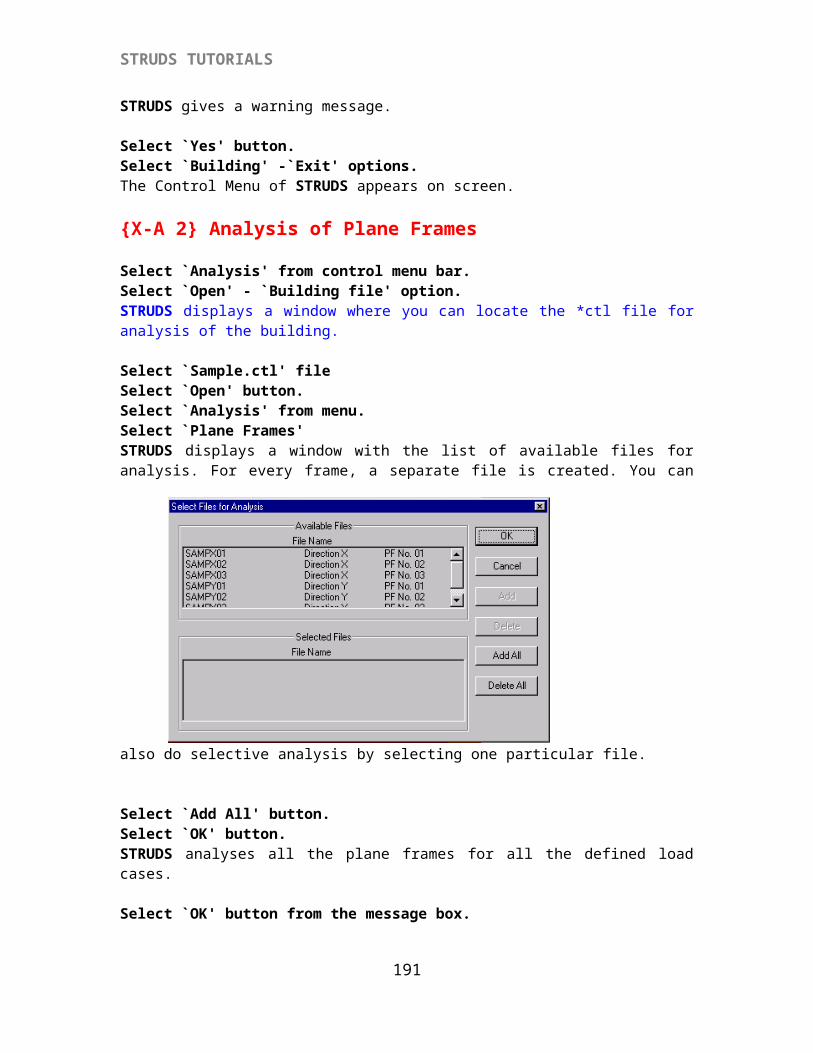
STRUDS TUTORIALS
Select `Load Combination' from menu bar.Select 'Beam' option.STRUDS displays a window with the list of defined load cases at the left.
Select `New' button.(optional)Select `DL' from the list.Write 1.1 in the field provided for the field of DL below the list.Select `Add' button.Select `LL' from listWrite `1.1' in the field.Select `Add' button.Select `WLX+' from the list.Write `1.1' in the field.Select `Add' button.Select `Close' button.This way you have specified a load combination of 1.1DL + 1.1 LL + 1.1 WLX+Similarly you can create any other load combinations as desired by you. STRUDS can design the structure for any of the load combination or the worst load combination.Select `Close' button.
{X-B 3.2 } Beam Design By Space Frame Method
Select `Beam' from menu.Select `Settings' from menu.STRUDS displays a window box with several fields and buttons. You can use the options in this window to specify the basic parameters for beam design.
191
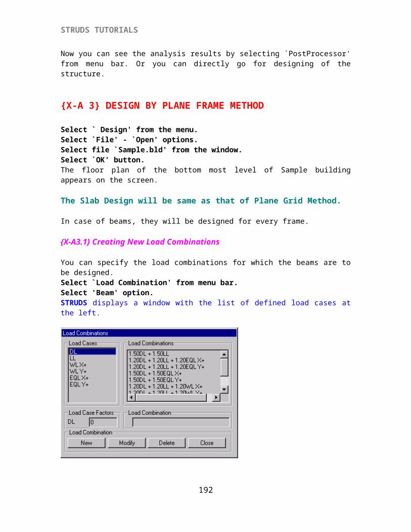
STRUDS TUTORIALS
Select `Reinforcement' button.STRUDS displays another window to specify the reinforcement parameters. You can again change these parameters as per your discretion.
Select 'Stirrup Grade': Fe250Select 'Stirrup Dia' : 6 mmSelect `OK' button.
Select `Beam' from menuSelect `Space Frame' option.
STRUDS displays the following window.
192
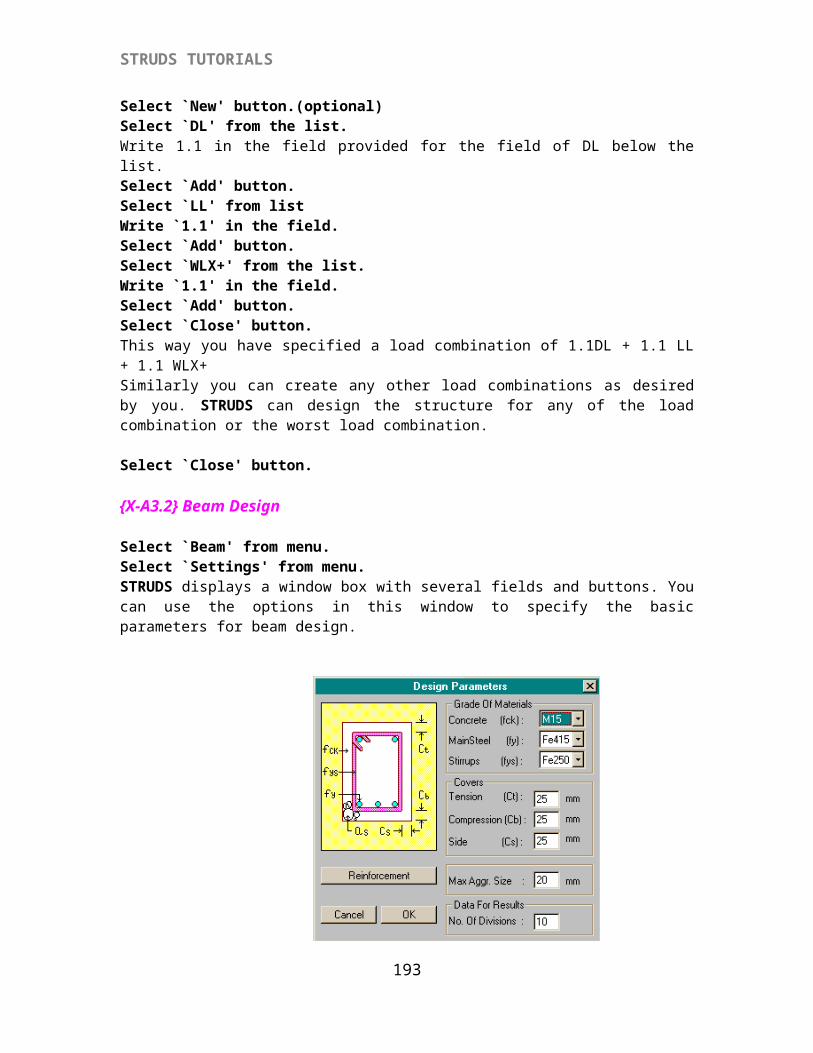
STRUDS TUTORIALS
Select Floor ID ; 1Click ‘OK’
Select `Design' from menu.Select `New'STRUDS displays a window showing all the load combinations specified by you in addition to the worst load combination.
Select `Worst Load Combination' from the list.STRUDS displays a message.
Click 'Yes' to change the beam properties.STRUDS displays a dialog box
193
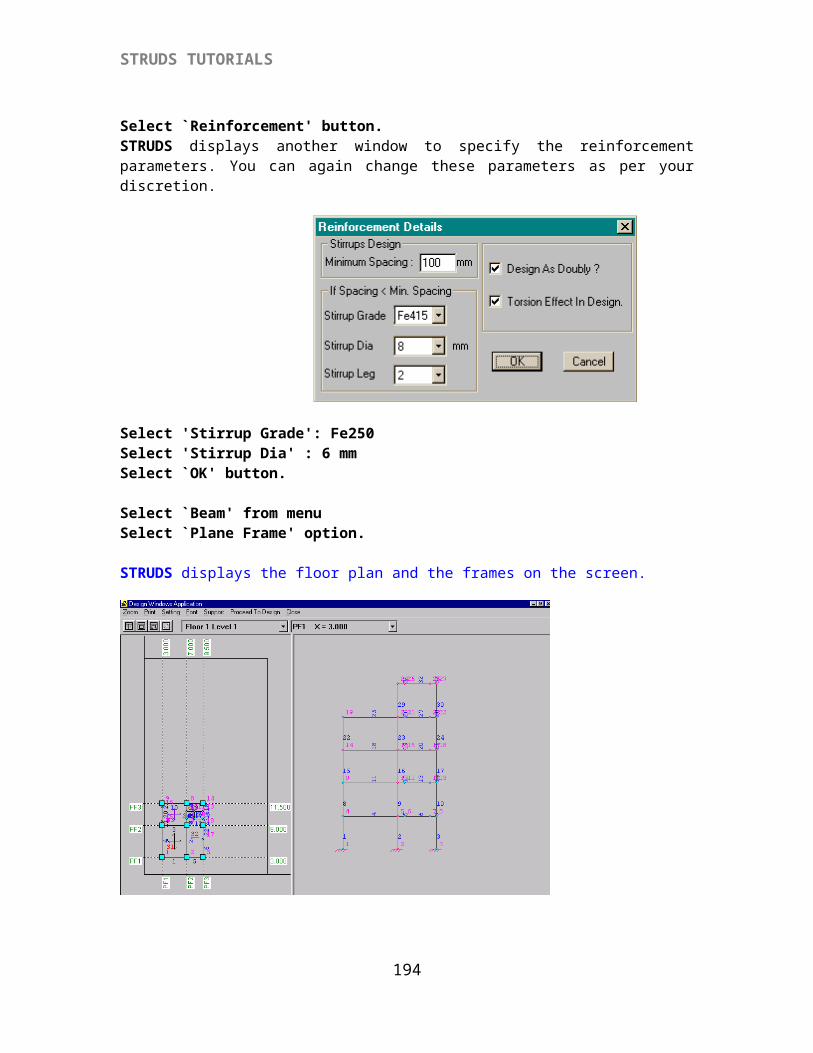
STRUDS TUTORIALS
Click 'Change' button.It displays another window
Click 'Close' button.Click 'Save' button.Click 'Close' button.
{X- B 3.3} To Save Design
Select `Design' from the menu.Select `Save' from the menu.
{X- B3.4} Grouping Of Beams
Select 'Grouping' from the menu.Select 'Auto' option.
Select 'Marking' from the menu.Select 'Auto' option.
{X- B 3.5} To View Beam Schedule
Select `Report' from the menu.Select `Schedule' option.STRUDS displays a text report of the design schedule of all the beams. You can print this report by using `Print' option from the menu. You can also change the fonts etc. of the text by using `Setting' option from the menu.Select `Close'
{X- B 3.6} To Save Design
Select `Report' from menu bar.
194
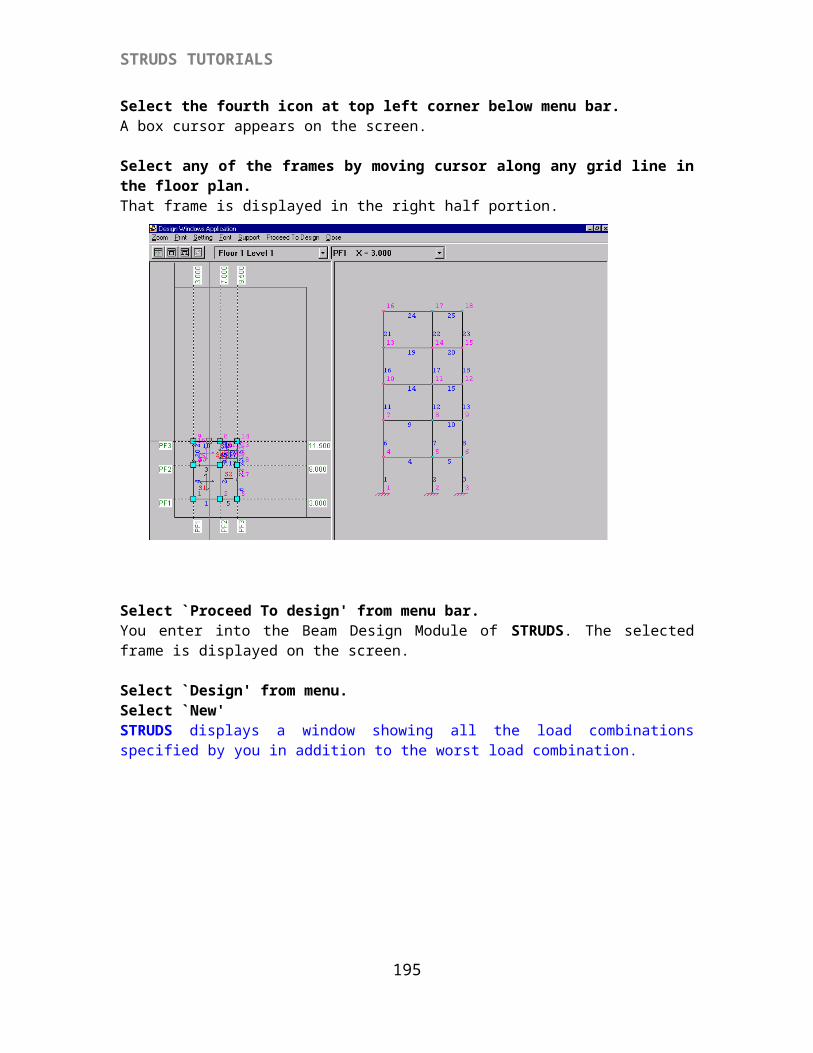
STRUDS TUTORIALS
Select `Bar Bending' option.STRUDS displays the bar bending schedule report for all the bars in every beam. The shape of bar types is also indicated at the end of this report.
Select `Close' option. Select `Report' from menu.Select `Quantity' option.STRUDS displays a text report for the quantity of steel and concrete required for all the beams. You can obtain the print of this report by using `Print' option from the menu. You can also change the Units or the font sizes of text by using `Settings' option from the menu.
Select `Close' from the menu.Select `SelectGrid' from menu.A box type cursor appears on the screen.
Select B1 by cursor.The entire continuos beam comprising B1, B2 appears on the screen. A menu is displayed at the top.
{X- B 3.7} To View Analysis Results
Select `Analysis Results' from menu bar.Select `SF Diagram' option.
195
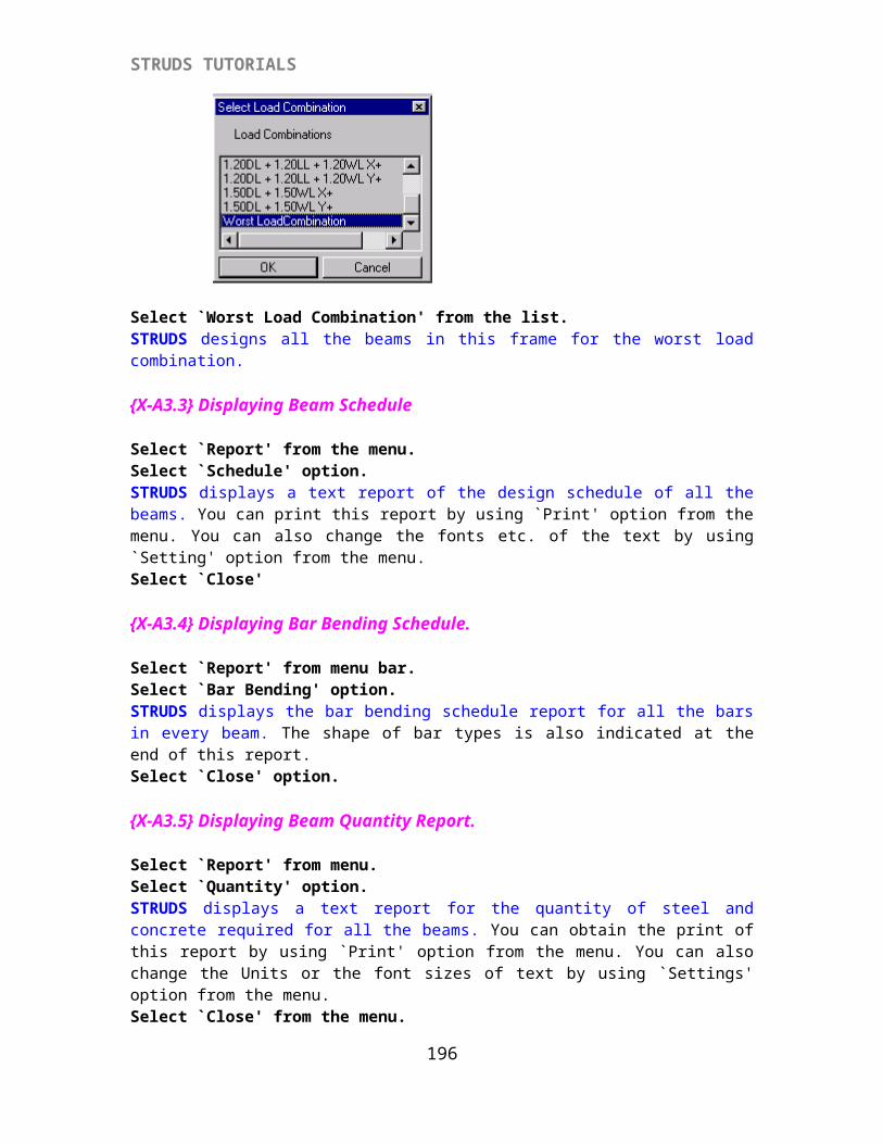
STRUDS TUTORIALS
STRUDS displays the Shear Force Diagram of the continuos beam. The shear values are shown at the right hand side in a small window. STRUDS displays the SF values the first beam from left end. You can see the SF values of other beams by using the up and down arrows of the beam labels field.
Select `Analysis Results'.Select `BM Diagram'. STRUDS displays the Bending Moment Diagram of the continuous beam. The bending moment values are shown at the right hand side in a small window. STRUDS displays the BM values the first beam from left end. You can see the BM values of other beams by using the up and down arrows of the beam labels field.
Select `Analysis Results' from the menu.Select `Common' option. This option allows you to visualize both BMD and SFD together STRUDS displays a window with check boxes.
Select the check boxes of GridLine, Shear Force and Bending Moment by cursor.Select `OK' button.STRUDS displays the gridline and its SFD & BMD on the screen.
Select `Close'Similarly you can use options `Def Diagram' and `Tor Diagram' to see the deflection diagram - values and torsion diagram - values of the selected gridline.
Select `Analysis Results'Select `Redist..' option.STRUDS displays a window with fields. This option is useful to distribute the moments in a beam. You can specify the percentage moment to be redistributed and STRUDS recalculates the moments. The design of this beam shall be done according to these revised moments.
Type 30 at the field for Left Node.Type 25 at the field for right node.Select `Redistribute' button from the window box.STRUDS displays the revised moments after redistribution. Similarly you can redistribute the moments for other beam spans.Select `Close' button.
{X- B 3.8} To View Design Results.
Select `Design Results' from menu.Select `Section Graphics' option.STRUDS displays the longitudinal section of the continuos beam. The cross section of beams is also displayed at the bottom half of the screen. STRUDS first displays the c/s of first beam from the left end at its support and mid-span. If you want to see the c/s of next beam -
Select `Cross Section' from menu.Select `Next' option.STRUDS displays the c/s of next beam span in the continuos beam. Similarly you can see the c/s of successive beams in a gridline.Select `Close' from menu.
196
STRUDS TUTORIALS
Select `Design Results' from menu.Select `Properties' option.By using this option, you can change the properties of all or any beam in the selected gridline. STRUDS displays a window box with several fields and buttons.
Select `Ast Bot..' button.STRUDS displays the areas of steel required at eleven points in the beam. You can note down the maximum area of steel required. Select `Close' button from the Design Values window.Now suppose you want to change the section of B1. Select `Section Geometry' button.Overwrite the depth of section as 0.38 in place of 0.45 in the field provided for depth.(optional)
Select `OK' button.Select `Save' button.Select `Close' button.STRUDS now automatically redesigns the beam for the revised section. This change is automatically carried out in Schedule, Quantity, Bar Bending report and Section Graphics.
Select `Design Results'.Select `Section Graphics'.You can see the change in beam depth and corresponding change in reinforcement.
Please note that here the analysis results remain same. The effect of change in analysis due to change in beam section is not considered. Only the design is changed as per revised section. If you want to take into account the effect on analysis due to change in section, you can change the section of that beam in preprocessor, reanalyze and redesign the beam.
Select `Close' from menu.Select `Close' from menu.The main menu of Beam design Module appears on the screen.
Select `Close' from the menu.STRUDS gives a warning message :
`Save Changes to design ?'
Select `No' button.This way you have designed the beams of selected floor plan of the structure.
Similarly you can design beams for other floors.
{X-B 3.9} Column Design By Spaceframe Method
Select `Column’ from Design Windows Application menu bar.The options `Orientation’ and `Grouping’ are the same as used in `Column’ menu of the Preprocessor.{X-B 3.10} Column NumberingSelect `Numbering’ option.
197
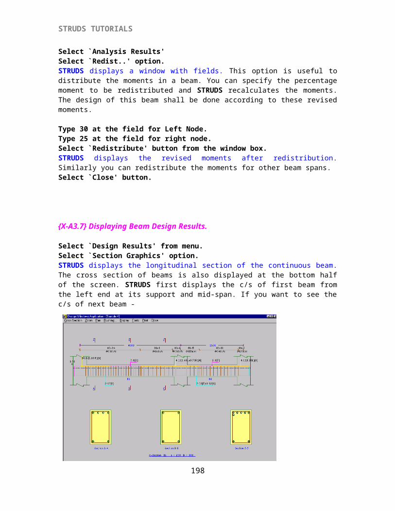
STRUDS TUTORIALS
This option allows you to provide the numbers to columns in the sequence specified by you. STRUDS displays a window which allows you to number the columns in four different ways. You can select any of the icon to select your numbering system.
Select `Close’ button from the window{X-B 3.11} Defining Design Properties
Select `Properties' option.A window appears on the screen with several fields and buttons. You can set the basic parameters like grade of concrete, grade of steel, minimum eccentricity, concrete cover etc. by using the options in this window.
You can also set the reinforcement parameters of the columns.Click 'Select Bar Diameters' button.STRUDS displays the following window.
198
STRUDS TUTORIALS
Select the Bar Diameters from the 'Available' list by double clicking on the required bar diameter.Select 16, 20.Click 'OK'Click on the check box for 'Change Size Internally'Click on the check box for 'Consider Live Load Reduction'
Select `Reinforcement Parameters’ button
You can change the parameters by overwriting the values in the field of this window.
Select `OK' button.
Select `Column’ - `Space Frame’ option.STRUDS reads all the reaction files from the analysis of space frame. The floor plan of bottom-most floor is displayed on the screen.
Select `Design’ from the menu.Select `New’ - `Biaxial’ options.STRUDS starts design of all the columns for all defined load combinations. The final design is for the worst load combination out of the defined load combinations. STRUDS displays a warning message.
199
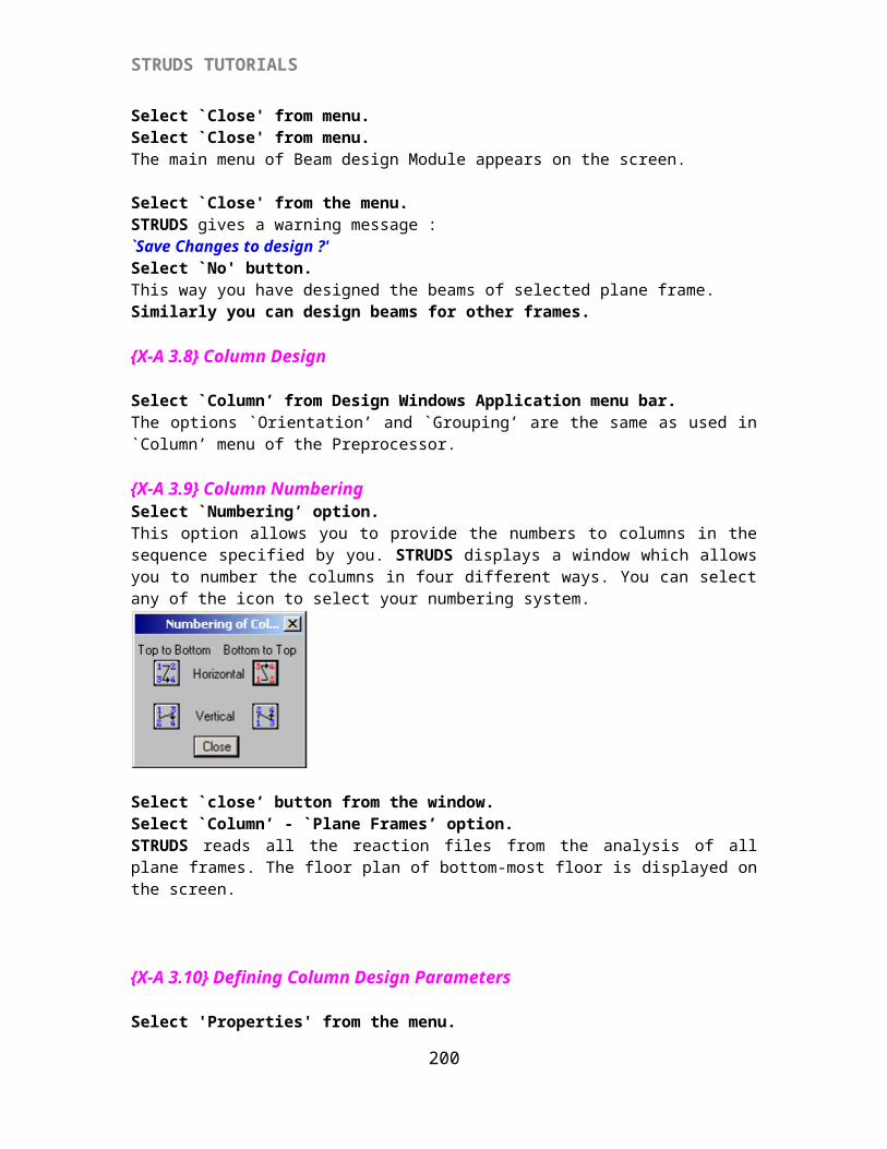
STRUDS TUTORIALS
Select the check box for`Change bar combination’ option.Key in 2 in the check box for N1 and Key in 16 in the check box for D1.Select `Redesign’ option.STRUDS redesigns the column. And displays the same message box again. This is because it is designing each column at every floor so you have to change the bar combination whenever required.. ORSelect `Ignore’ button. (optional)Similarly you can select `Ignore’ when ever the check for bar spacing is not satisfied and you can increase the column size when the maximum steel percentage exceeds the limit.{X-B 3.12} Saving Column Design
Select 'Design' from the menu.Select 'Save' option.{X-B 3.13} To View Design
Select `View design’ from menu.Select any column by cursor.STRUDS displays the design details of the selected column in a window box. All the parameters like axial load, moments about X and Y axes, size of the column, reinforcement area provided, bars & their numbers etc. are shown. If you want to change the size of column at any floor, you can do so by just overwriting the previous width and depth. Then you can select `Save’ and `Redesign’ buttons to allow the program redesign the column. Please note that here the P, Mx and My remain same. Only the effect of change in size in design is taken care of.Select `Close’ button.
{X-B 3.14} To View Loads Select `View Loads’ from menu.Select `Cumulative Loads’ option.By using this option you can see the cumulative loads coming on all columns at any floor. STRUDS displays a window box and a pull down menu providing the numbers of all floors.
200
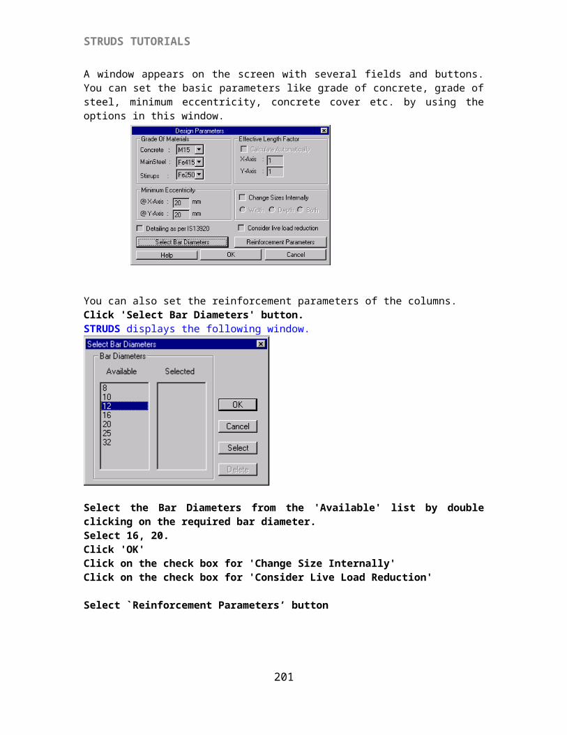
STRUDS TUTORIALS
Select the floor no. 1 from the menu.Select `OK’ button.STRUDS displays on screen the cumulative loads on all the columns. The loads are displayed in kNs.
Select `View Loads’ from menu.Select `Select Column’ option.Select any column by cursor.STRUDS displays the floor-wise axial loads and moments about X and Y for the selected column.Select `Close’ button.{X-B 3.15} To View Center Line PlanSelect 'Center Line' from menu.STRUDS computes the centerline distance of all the columns in both X and Y directions, from the origin.
Select 'Cross Section' from the menu.Select any column by cursor.The cross section of that column at bottom most floor is shown on screen. STRUDS also displays the reinforcement provided in the column. You can change the floor no. in the pull down menu to see the corresponding cross section of the column.
Select 'Close' from menu bar.
{X-B 3.16} To View Column Schedule Report
Select 'Report' from menu.Select 'Column Schedule' option.
STRUDS displays the column design schedule for all the columns. Floor-wise sizes, reinforcement of main bars, stirrup steel and grade of concrete is shown in the schedule. You can obtain a hard copy of this schedule by using 'Print' option from the menu.Select 'Close'.{X-B 3.17} To Column Quantity Report.
Select 'Report' from menu.Select 'Column Quantity' option.STRUDS displays the concrete and steel quantity required for all floors and all columns.Select 'Close'
Select 'Report' from the menu.Select 'Quantity Summary' from the menu.
STRUDS displays the summary of overall quantities of concrete, diameter-wise steel and shuttering area required per floor of the building for every column.Select 'Close' from the menu.{X-B 3.18} To View Column Load Report
Select 'Report' from the menu.Select 'Column Load' option.
201
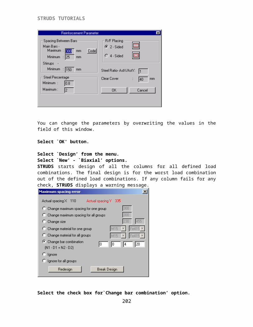
STRUDS TUTORIALS
STRUDS displays a report of loads coming on the column at every floor.Select 'Close'.{X-B 3.19} To View Detail Report Of Column Design.Select 'Report'.Select 'Column Design' option
STRUDS displays a text report of column design details. All the basic parameters for designing are displayed in this report.
Select `Report’Select `Schedule’ option.Select `Worst Load Combination’ option.STRUDS displays a text report of the floor-wise worst load combination of every column. A table is displayed for floor -wise design output and the load cases with factors for the worst load combination in the last column of the table.
Select `Close’ from menu.Select `Report’ from menu.Select `All load combinations’ option.STRUDS displays the design results of all columns for all load combinations in text form.
Select `Close’ option from menu.Select 'Close' option.Select 'Close' from menu to come out of the column design module.
The main menu of Design windows application again appears on the screen.
{X-B 3.20} Footing Design By Spaceframe MethodSelect `Footing’ Select ‘Spaceframe’ option.The main menu of Footing Design module appears on the screen. STRUDS displays the floor plan of the bottom most floor.
Select ‘Grouping’ option to group the footings as per the loads and the type of footings (optional).Select 'Properties' option.
STRUDS displays a window having several fields and buttons. You can specify by the basic parameters for footing design by exercising different options provided in this menu.
202
STRUDS TUTORIALS
Select 'Select Bar Diameter' button.STRUDS displays 'Select Bar Diameter' window.STRUDS selects bars of diameters 8mm, 10mm, 12mm by default.Select 8 mm bar from the 'Selected' list.Click 'Deselect' button.Select 12 mm bar from the 'Selected' list.Click 'Deselect' button.
Select 'Soil Parameters' button from the window. STRUDS displays a small window where you can specify the properties of soil.Select 'OK' button.Select 'OK' button from the Design Parameters window.
Select 'Design' from menu bar.
STRUDS designs all the footings in one stroke. If any footing fails for any of the design checks, STRUDS displays a warning message box. In this case the bond check for footing bars fails.
203
STRUDS TUTORIALS
Select the 'For All Group' optionSelect 'Depth' button from the Change option.STRUDS completes the design for all the footings.
{X-B 3.21} To Save Footing DesignSelect ‘Design’ option from menu.Select ‘Save’ option.
{X-B 3.22} To View Footing Design
Select `View Design' from menu.Select any of the footings by cursor. STRUDS displays the design results of that footing on the screen. The X and Y dimensions of the footing, edge depth, main depth and steel provided are shown in the window box. You can also change one of the dimensions of footing. STRUDS will then automatically redesign the footing and calculate the steel required for the revised size.Select `Close' button.
{X-B 3.23} To View Plan + Elevation
Select `View Plan+Elevation' from the menu.A box type cursor appears on screen. You can select any of the footings by moving cursor and clicking the left button of the mouse.STRUDS displays the reinforcement plan and cross sections about both axes of the selected footing. At the top, below menu bar, three icons are displayed. You can click these icons to see the plan and cross sections simultaneously or separately.Select `Close' option from menu bar.
{X-B 3.24} To View Footing Schedule
Select `Report' from menu.Select `Schedule' option.STRUDS displays the footing design schedule for all the footings.You can get a print out of this schedule by using the `Print' option from menu. You can also see the print preview of this report by using options `Print' - `Preview' from the menu.Select `Close' from the menu bar.
204
STRUDS TUTORIALS
{X-B 3.25} To View Footing Quantity Report.
Select `Report' from the menu.Select `Quantity' option.STRUDS displays the quantity report for all the footings.Select `Close'{X-B 3.26} To View Footing Centerline Plan.
Select `CenterLine' from menuSelect `Draw CenterLine' option.STRUDS displays the foundation plan of all the footings showing centers of footings, pit sizes, footing sizes and reinforcement provided in every footing. You can put on/off the display in this graphics screen as -
Select `CenterLine' from the menu.Select `Display Settings' option.All the display settings by default are put on. You can put off say footing bars in X direction by clicking on that option. When you again click on the same option, the display is put on.Similarly you can use the options `CenterLine' - `Font Settings' to change the font sizes and font types of the text shown on the screen.
205
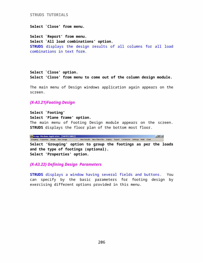
STRUDS TUTORIALS
Select `Close' to come out of the footing design module. This way you have designed beams, columns and footings of the sample building by Space Frame method.
206
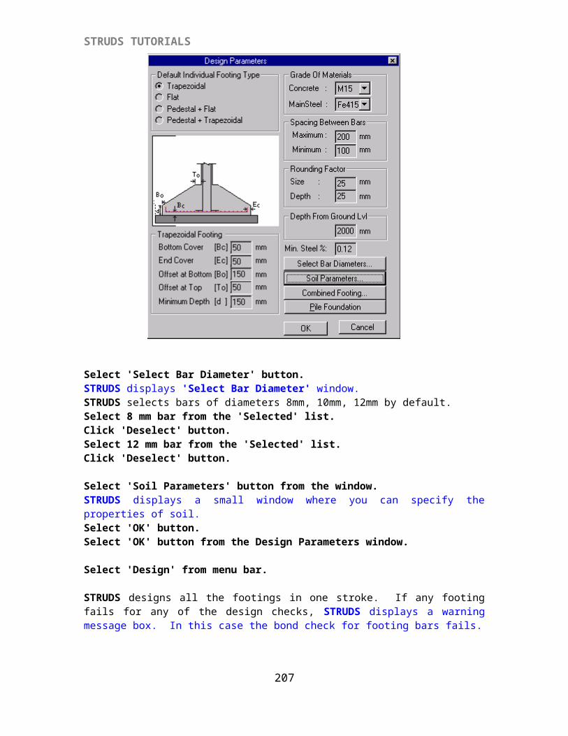
STRUDS TUTORIALS
207