STRUCTURED NODES IN UML 2.0 ACTIVITES · Key words: UML 2.0, activity diagrams, structured nodes,...
24
Nordic Journal of Computing STRUCTURED NODES IN UML 2.0 ACTIVITES HARALD ST ¨ ORRLE Ludwig-Maximilians-Universit¨ at M¨ unchen Oettingenstr. 67, 80538 M¨ unchen, GERMANY [email protected] Abstract. The upcoming major revision of the UML (see OMG [2003]) has intro- duced significant changes and additions to “the lingua franca of Software Engineering”. Within the UML, activity diagrams are particularly prominent, since they are the natural choice when it comes to the modeling of web-services, workflows, and service-oriented architectures. One of the most novel concepts introduced are so called structured nodes (StructuredActivityNodes in the metamodel). This concept includes features like loops, expansion regions, collection valued parameters, and data streaming. Building on substantial previous work by the author, the purpose of this paper is to understand better these new concepts and notations, and actually defines a semantics for them. Since the UML standard is still immature in some parts, this article is restricted to those concepts, for which a reliable interpretation is currently possible. This article is followup to St¨ orrle [2004d]. ACM CCS Categories and Subject Descriptors: D.2.1, D.2.2, D.2.10, D.3.3 Key words: UML 2.0, activity diagrams, structured nodes, loops, collection-valued pa- rameters, streaming 1. Introduction The modeling of business processes and workflows is an important area in in- dustrial software engineering, and, given that it crucially involves domain-experts which are usually non-programmers, it is one of those areas, where model-driven approaches definitely have a competitive edge over code-driven approaches. As the UML has become the “lingua franca of software engineering” and is the cor- nerstone of the Model Driven Architecture initiative of the OMG, it is a natural choice for this task. Within the UML, activity diagrams are generally considered to be the appropriate notation for modeling business processes, workflows, and system-level behaviors, such as the composition of web-services. Unfortunately, the ActivityGraphs 1 of UML 1.5 have certain shortcomings in this respect, one of which is the lack of structuring mechanisms within ActivityGraphs. The only way to model non-linear control- and data flow is the DecisionNode (depicted by a diamond-shaped symbol), that is, a goto, with all its negative repercussions. In programming languages, the goto-construct has long since been abandoned. Modern programming languages offer a whole range of structuring constructs like 1 Adopting the convention of the standard, words in “CamelCaps” refer to meta-classes. Received October 8, 2004.
Transcript of STRUCTURED NODES IN UML 2.0 ACTIVITES · Key words: UML 2.0, activity diagrams, structured nodes,...
Nordic Journal of Computing
STRUCTURED NODES IN UML 2.0 ACTIVITES
HARALD STORRLELudwig-Maximilians-Universitat Munchen
Oettingenstr. 67, 80538 Munchen, [email protected]
Abstract. The upcoming major revision of the UML (see OMG [2003]) has intro-duced significant changes and additions to “the lingua franca of Software Engineering”.Within the UML, activity diagrams are particularly prominent, since they are the naturalchoice when it comes to the modeling of web-services, workflows, and service-orientedarchitectures. One of the most novel concepts introduced are so called structured nodes(StructuredActivityNodes in the metamodel). This concept includes features like loops,expansion regions, collection valued parameters, and data streaming.
Building on substantial previous work by the author, the purpose of this paper is tounderstand better these new concepts and notations, and actually defines a semantics forthem. Since the UML standard is still immature in some parts, this article is restrictedto those concepts, for which a reliable interpretation is currently possible. This article isfollowup to Storrle [2004d].
ACM CCS Categories and Subject Descriptors:D.2.1, D.2.2, D.2.10, D.3.3
Key words: UML 2.0, activity diagrams, structured nodes, loops, collection-valued pa-rameters, streaming
1. Introduction
The modeling of business processes and workflows is an important area in in-dustrial software engineering, and, given that it crucially involves domain-expertswhich are usually non-programmers, it is one of those areas, where model-drivenapproaches definitely have a competitive edge over code-driven approaches. Asthe UML has become the “lingua franca of software engineering” and is the cor-nerstone of the Model Driven Architecture initiative of the OMG, it is a naturalchoice for this task. Within the UML, activity diagrams are generally consideredto be the appropriate notation for modeling business processes, workflows, andsystem-level behaviors, such as the composition of web-services. Unfortunately,the ActivityGraphs1 of UML 1.5 have certain shortcomings in this respect, oneof which is the lack of structuring mechanisms within ActivityGraphs. The onlyway to model non-linear control- and data flow is the DecisionNode (depicted by adiamond-shaped symbol), that is, a goto, with all its negative repercussions.
In programming languages, the goto-construct has long since been abandoned.Modern programming languages offer a whole range of structuring constructs like
1 Adopting the convention of the standard, words in “CamelCaps” refer to meta-classes.
Received October 8, 2004.
2 HARALD STORRLE
different kinds of loops, properly nested if/then/else or case/otherwise expressions,exceptions, transactions and more. None of these are present in UML 1.x. Un-surprisingly, some people consider the ActivityGraphs of UML 1.5 as “spaghetti-diagrams”. And consequently, the OMG has addressed this problem by adding theconcept of StructuredActivityNode (“structured node”, for simplicity) in the newversion of the UML.
However, all of these constructs are new in the UML. For some of them, there isthe experience from programming languages or other notations to guide us. Forinstance, exceptions in, say, Java, or conditional nodes in Nassi-Shneiderman-Diagrams. Some other constructs, however, seem to be new altogether, likeExpansionRegions. In either case, there is little to no experience yet as to howthese constructs integrate with the rest of UML activity diagrams.
Also, it is currently unclear what the precise semantics of these new conceptsis, for in the standard this is described only in a very superficial way, without theformal rigor necessary for practical model exchange, or enactment, or verificationtools. In fact, the standard does not even provide adequate examples to illustratethe intention behind these constructs and to clarify their meaning.
This paper thus explores the new notions both syntactically and pragmatically,striving to provide a plausible and viable interpretation for the various types ofStructured Activity Nodes, including at least a partially formal definition of theirsemantics. Be warned that the UML is a moving target, however, and so this paperis restricted to those concepts for which an interpretation can be currently pro-vided with sufficient validity; for the remaining concepts, some interpretations areoffered, but they are more on the speculative side (see section 5).
2. Activity diagrams
Activity diagrams serve many purposes, during many phases of the software life-cycle, and are a tool for many roles:◦ They are intended for being used for describing all process-like structures,
e.g. business processes, software processes, use case behaviors, web services,and algorithmic structures of programs, though other purposes like hardware-descriptions are also conceivable.
◦ Activity diagrams are thus applicable throughout the whole software lifecy-cle, i.e., during business modeling, acquisition, analysis, design, testing, andoperation, and in fact in many other activities.
◦ Thus, they are intended for usage not just by Software-Architects andSoftware-Engineers, but also by domain specialists, programmers, admin-istrators and so on.
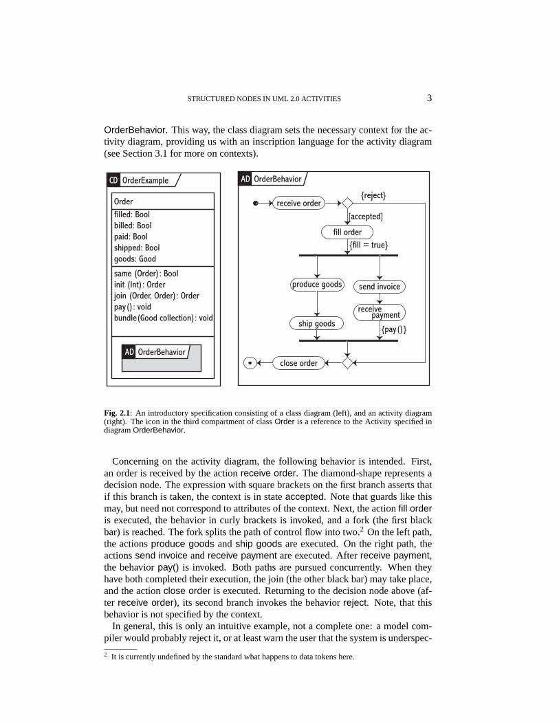
Activity diagrams are best explained by means of an example (see Figure 2.1,adapted from OMG [2003, Fig. 203, p. 290]). The example consists of two dia-grams, a class diagram (left) and an activity diagram (right). Note, that the classOrder has a third compartment that contains a reference to the activity diagram
STRUCTURED NODES IN UML 2.0 ACTIVITIES 3
OrderBehavior. This way, the class diagram sets the necessary context for the ac-tivity diagram, providing us with an inscription language for the activity diagram(see Section 3.1 for more on contexts).
Orderfilled: Boolbilled: Boolpaid: Boolshipped: Boolgoods: Good
same (Order): Boolinit (Int): Order join (Order, Order): Orderpay(): voidbundle(Good collection): void
ship goods
receive order
fill order
close order
send invoice
receivepayment
{pay()}
{reject}
[accepted]
{fill = true}
produce goods
OrderExampleCD OrderBehaviorAD
OrderBehaviorAD
Fig. 2.1: An introductory specification consisting of a class diagram (left), and an activity diagram(right). The icon in the third compartment of classOrder is a reference to the Activity specified indiagramOrderBehavior.
Concerning on the activity diagram, the following behavior is intended. First,an order is received by the actionreceive order. The diamond-shape represents adecision node. The expression with square brackets on the first branch asserts thatif this branch is taken, the context is in stateaccepted. Note that guards like thismay, but need not correspond to attributes of the context. Next, the actionfill orderis executed, the behavior in curly brackets is invoked, and a fork (the first blackbar) is reached. The fork splits the path of control flow into two.2 On the left path,the actionsproduce goods andship goods are executed. On the right path, theactionssend invoice andreceive payment are executed. Afterreceive payment,the behaviorpay() is invoked. Both paths are pursued concurrently. When theyhave both completed their execution, the join (the other black bar) may take place,and the actionclose order is executed. Returning to the decision node above (af-ter receive order), its second branch invokes the behaviorreject. Note, that thisbehavior is not specified by the context.
In general, this is only an intuitive example, not a complete one: a model com-piler would probably reject it, or at least warn the user that the system is underspec-
2 It is currently undefined by the standard what happens to data tokens here.
4 HARALD STORRLE
ified. It is also arguably the case, that the problem in question should be modeledin a different way, but for the sake of argument, I will stick to this example, sinceit is the one used throughout the standard itself.
This example goes beyond the UML standard, in that each diagram is put intoa frame denoting its type and name, while the standard defines this only for inter-action diagrams. It is good practice, however, and should be followed, wheneverspecifying a system. Observe that it is only this feature that allows us to spec-ify OrderBehavior separately in a digram of its own, and reference it from withinthe third compartment ofOrder. The procedure proposed in the UML standardwould require us to draw the whole Activity (and only a single one!) in the thirdcompartment.
3. Activities
A detailed discussion of the concrete and abstract syntax of UML 2.0 Activities,the semantic domains of procedural and colored Petri-nets, respectively, and thesemantic mapping of control- and data-flow, and exceptions of Activities is foundin Storrle [2004b], Storrle [2004a], and Storrle [2004c].
In UML, the abstract syntax is defined by the metamodel (also called abstractsyntax). The various notations and digram types are the concrete syntax. Theconcept underlying the notation of activity diagrams is called Activity. In thissection, this concept and related metaclasses are explained.
3.1 Abstract syntax
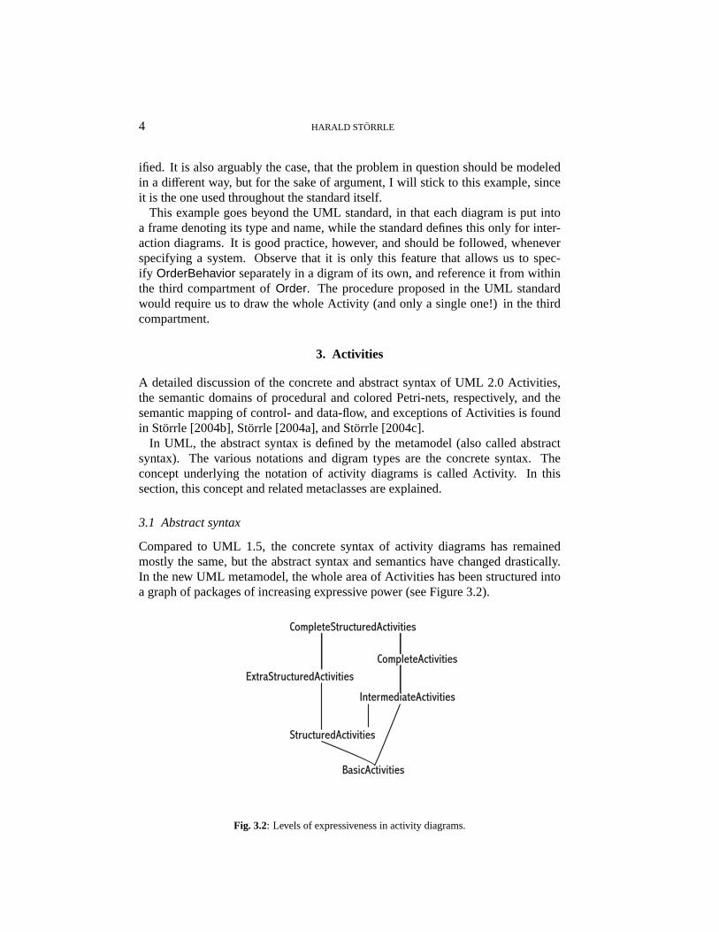
Compared to UML 1.5, the concrete syntax of activity diagrams has remainedmostly the same, but the abstract syntax and semantics have changed drastically.In the new UML metamodel, the whole area of Activities has been structured intoa graph of packages of increasing expressive power (see Figure 3.2).
BasicActivities
StructuredActivities
IntermediateActivities
CompleteActivities
CompleteStructuredActivities
ExtraStructuredActivities
Fig. 3.2: Levels of expressiveness in activity diagrams.
STRUCTURED NODES IN UML 2.0 ACTIVITIES 5
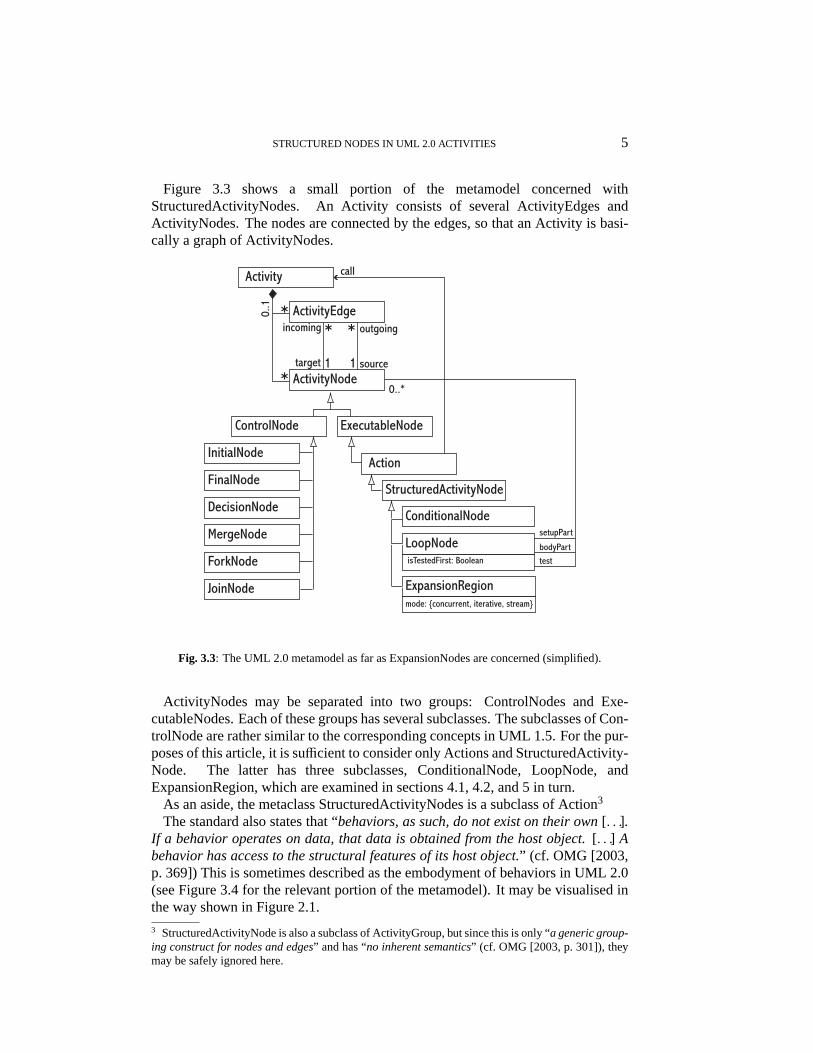
Figure 3.3 shows a small portion of the metamodel concerned withStructuredActivityNodes. An Activity consists of several ActivityEdges andActivityNodes. The nodes are connected by the edges, so that an Activity is basi-cally a graph of ActivityNodes.
ControlNode
InitialNode
FinalNode
DecisionNode
MergeNode
ForkNode
JoinNode
*
0..1
1
ExecutableNode
ActivityEdge
ActivityNode
Activity
outgoingincoming
target source1
**
*
call
Action
ConditionalNode
StructuredActivityNode
LoopNode
ExpansionRegionmode: {concurrent, iterative, stream}
isTestedFirst: Boolean
0..*
setupPart
bodyParttest
Fig. 3.3: The UML 2.0 metamodel as far as ExpansionNodes are concerned (simplified).
ActivityNodes may be separated into two groups: ControlNodes and Exe-cutableNodes. Each of these groups has several subclasses. The subclasses of Con-trolNode are rather similar to the corresponding concepts in UML 1.5. For the pur-poses of this article, it is sufficient to consider only Actions and StructuredActivity-Node. The latter has three subclasses, ConditionalNode, LoopNode, andExpansionRegion, which are examined in sections 4.1, 4.2, and 5 in turn.
As an aside, the metaclass StructuredActivityNodes is a subclass of Action3
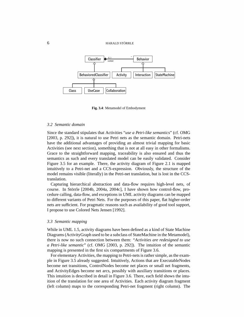
The standard also states that “behaviors, as such, do not exist on their own[. . .].If a behavior operates on data, that data is obtained from the host object.[. . .] Abehavior has access to the structural features of its host object.” (cf. OMG [2003,p. 369]) This is sometimes described as the embodyment of behaviors in UML 2.0(see Figure 3.4 for the relevant portion of the metamodel). It may be visualised inthe way shown in Figure 2.1.
3 StructuredActivityNode is also a subclass of ActivityGroup, but since this is only “a generic group-ing construct for nodes and edges” and has “no inherent semantics” (cf. OMG [2003, p. 301]), theymay be safely ignored here.
6 HARALD STORRLE
Classifier
StateMachine
Behavior
InteractionActivity
context0..1 *
BehavioredClassifier
Class UseCase Collaboration
Fig. 3.4: Metamodel of Embodyment
3.2 Semantic domain
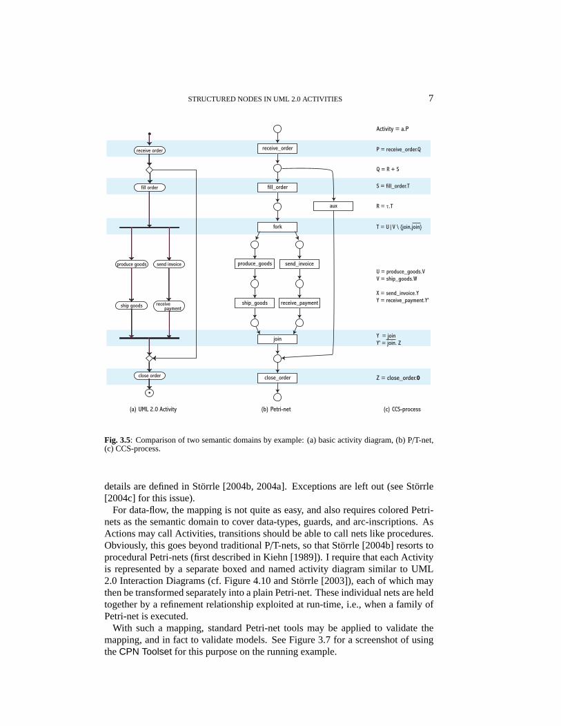
Since the standard stipulates that Activities “use a Petri-like semantics” (cf. OMG[2003, p. 292]), it is natural to use Petri nets as the semantic domain. Petri-netshave the additional advantages of providing an almost trivial mapping for basicActivities (see next section), something that is not at all easy in other formalisms.Grace to the straightforward mapping, traceability is also ensured and thus thesemantics as such and every translated model can be easily validated. ConsiderFigure 3.5 for an example. There, the activity diagram of Figure 2.1 is mappedintuitively to a Petri-net and a CCS-expression. Obviously, the structure of themodel remains visible (literally) in the Petri-net translation, but is lost in the CCS-translation.
Capturing hierarchical abstraction and data-flow requires high-level nets, ofcourse. In Storrle [2004b, 2004a, 2004c], I have shown how control-flow, pro-cedure calling, data-flow, and exceptions in UML activity diagrams can be mappedto different variants of Petri Nets. For the purposes of this paper, flat higher-ordernets are sufficient. For pragmatic reasons such as availability of good tool support,I propose to use Colored Nets Jensen [1992].
3.3 Semantic mapping
While in UML 1.5, activity diagrams have been defined as a kind of State MachineDiagrams (ActivityGraph used to be a subclass of StateMachine in the Metamodel),there is now no such connection between them: “Activities are redesigned to usea Petri-like semantic” (cf. OMG [2003, p. 292]). The intuition of the semanticmapping is presented in the first six compartments of Figure 3.6.
For elementary Activities, the mapping to Petri-nets is rather simple, as the exam-ple in Figure 3.5 already suggested. Intuitively, Actions that are ExecutableNodesbecome net transitions, ControlNodes become net places or small net fragments,and ActivityEdges become net arcs, possibly with auxiliary transitions or places.This intuition is described in detail in Figure 3.6. There, each field shows the intu-ition of the translation for one area of Activities. Each activity diagram fragment(left column) maps to the corresponding Petri-net fragment (right column). The
STRUCTURED NODES IN UML 2.0 ACTIVITIES 7
(a) UML 2.0 Activity (b) Petri-net
receive_order
fill_order
fork
(c) CCS-process
Activity = a.P
P = receive_order.Q
Q = R + S
S = fill_order.T
Z = close_order.0
U = produce_goods.VV = ship_goods.W
X = send_invoice.YY = receive_payment.Y'
T = U|V \ {join,join}
ship goods
receive order
fill order
close order
send invoice
receivepayment
produce goods produce_goods
ship_goods receive_payment
send_invoice
aux
join
close_order
R = τ.T
Y = joinY' = join. Z
Fig. 3.5: Comparison of two semantic domains by example: (a) basic activity diagram, (b) P/T-net,(c) CCS-process.
details are defined in Storrle [2004b, 2004a]. Exceptions are left out (see Storrle[2004c] for this issue).
For data-flow, the mapping is not quite as easy, and also requires colored Petri-nets as the semantic domain to cover data-types, guards, and arc-inscriptions. AsActions may call Activities, transitions should be able to call nets like procedures.Obviously, this goes beyond traditional P/T-nets, so that Storrle [2004b] resorts toprocedural Petri-nets (first described in Kiehn [1989]). I require that each Activityis represented by a separate boxed and named activity diagram similar to UML2.0 Interaction Diagrams (cf. Figure 4.10 and Storrle [2003]), each of which maythen be transformed separately into a plain Petri-net. These individual nets are heldtogether by a refinement relationship exploited at run-time, i.e., when a family ofPetri-net is executed.
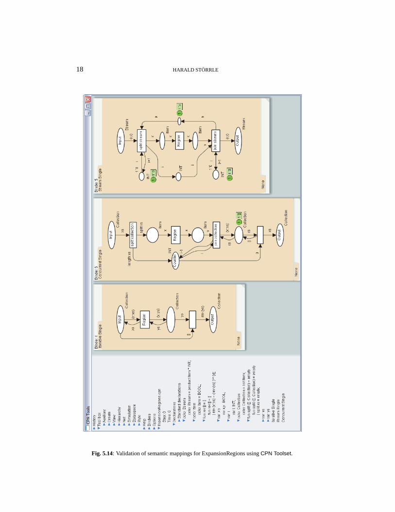
With such a mapping, standard Petri-net tools may be applied to validate themapping, and in fact to validate models. See Figure 3.7 for a screenshot of usingtheCPN Toolset for this purpose on the running example.

8 HARALD STORRLE
activityactivity
ExecutableNodes
fork/join
ControlNodes except:
auxiliary
unless:
ActivityEdges
ObjectNodesTYPE
TYPEObjectFlows
expr expr
Petri-netsUML ADs Petri-netsUML ADs
Fig. 3.6: The intuition of the semantic mapping for Activities. Actions that call Activities are repre-sented as Petri-net transitions with a double outline. They are translated into refined transitions of aprocedural Petri-net.
4. Simple StructuredActivityNodes
In this section, ConditionalNodes and LoopNodes are explained. They can be ex-plained in terms of syntactic sugaring of more elementary constructs, the semanticsof which has been defined in Storrle [2004b, 2004a] (see also Section 3.3 above).
4.1 ConditionalNodes
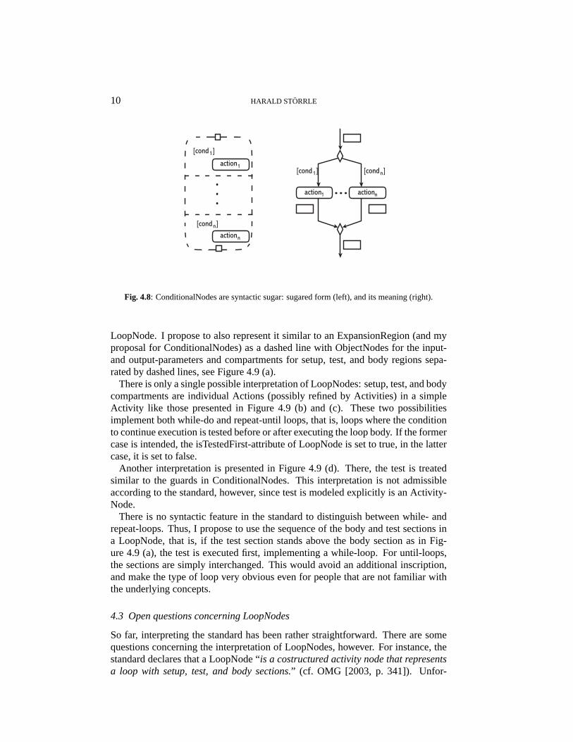
A ConditionalNode is a kind of set of guarded commands: “a conditional node is astructured activity node that represents an exclusive choice among some number ofalternatives.” (cf. OMG [2003, p. 313]). Each consists of a set of “clauses, [eachconsisting] of a test section and a body section”. When executing a Condition-alNode, all tests are executed. Then, the body section of one of those that yieldedtrue is chosen nondeterministically and executed. Alternatively, “sequencing con-straints may be specified among clauses”.
The standard gives no hint concerning the concrete syntax of a conditional node.Thus, I propose a representation similar to that of ExpansionRegion, namely adashed box with Pins (i.e., ObjectNodes) for the input- and output-parameters andone compartment for each pair of condition and consequence, separated by dashedlines (see Figure 4.8, left).
In order to reduce complexity, I propose that the test sections be side-effect free.Thus, it is probably the easiest to use the guards introduced with DecisionNodes.Also, I suggest that the body section consist of single Actions. These may callupon other Activities, of course. Then, ConditionalNodes are just syntactic sugar,

STRUCTURED NODES IN UML 2.0 ACTIVITIES 9
Fig. 3.7: Validation the semantic mapping in general and specific models in particular using theCPNToolset.
and their meaning is best defined by an expansion into more basic constructs. Fig-ure 4.8 (right) shows how this may be done.
4.2 LoopNodes
A loop node has “setup, test, and body sections” (cf. OMG [2003, p. 341]), allof which consist of a set of ActivityNodes. Also, “the test section may precede orfollow the body section”(ibid.), depending on the value of the attribute isTestedFirst(see Figure 3.1). Also, “the setup section is executed once on entry to the loop, andthe test and body sections are executed repeatedly until the test produces a falsevalue”(ibid.).
Additionally, a loop node may have several OutputPins for outputting variousvalues, including the loop variable, the test value, and so on (these are ignored inthe remainder). The initial value for the loop variable is provided on an InputPin.Note, that intermediate values may be stored in the context.
As with conditional nodes, the standard gives no hint on the concrete syntax of a
10 HARALD STORRLE
[cond ]1
n[cond ]
[cond ]1 n[cond ]
action1 actionn
1action
naction
Fig. 4.8: ConditionalNodes are syntactic sugar: sugared form (left), and its meaning (right).
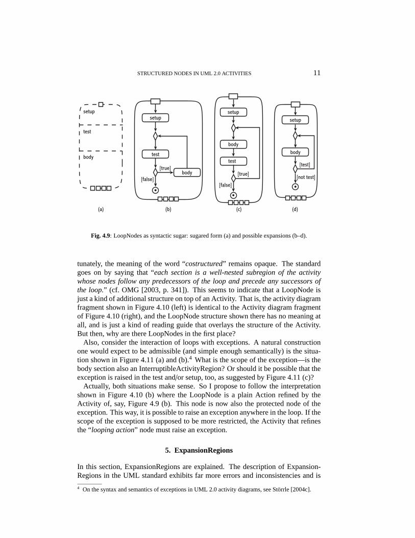
LoopNode. I propose to also represent it similar to an ExpansionRegion (and myproposal for ConditionalNodes) as a dashed line with ObjectNodes for the input-and output-parameters and compartments for setup, test, and body regions sepa-rated by dashed lines, see Figure 4.9 (a).
There is only a single possible interpretation of LoopNodes: setup, test, and bodycompartments are individual Actions (possibly refined by Activities) in a simpleActivity like those presented in Figure 4.9 (b) and (c). These two possibilitiesimplement both while-do and repeat-until loops, that is, loops where the conditionto continue execution is tested before or after executing the loop body. If the formercase is intended, the isTestedFirst-attribute of LoopNode is set to true, in the lattercase, it is set to false.
Another interpretation is presented in Figure 4.9 (d). There, the test is treatedsimilar to the guards in ConditionalNodes. This interpretation is not admissibleaccording to the standard, however, since test is modeled explicitly is an Activity-Node.
There is no syntactic feature in the standard to distinguish between while- andrepeat-loops. Thus, I propose to use the sequence of the body and test sections ina LoopNode, that is, if the test section stands above the body section as in Fig-ure 4.9 (a), the test is executed first, implementing a while-loop. For until-loops,the sections are simply interchanged. This would avoid an additional inscription,and make the type of loop very obvious even for people that are not familiar withthe underlying concepts.
4.3 Open questions concerning LoopNodes
So far, interpreting the standard has been rather straightforward. There are somequestions concerning the interpretation of LoopNodes, however. For instance, thestandard declares that a LoopNode “is a costructured activity node that representsa loop with setup, test, and body sections.” (cf. OMG [2003, p. 341]). Unfor-
STRUCTURED NODES IN UML 2.0 ACTIVITIES 11
(a) (b) (c) (d)
setup
body
[test]
[not test]
setup
test
body[true]
[false]
setup
body
test
[true]
[false]
test
setup
body
Fig. 4.9: LoopNodes as syntactic sugar: sugared form (a) and possible expansions (b–d).
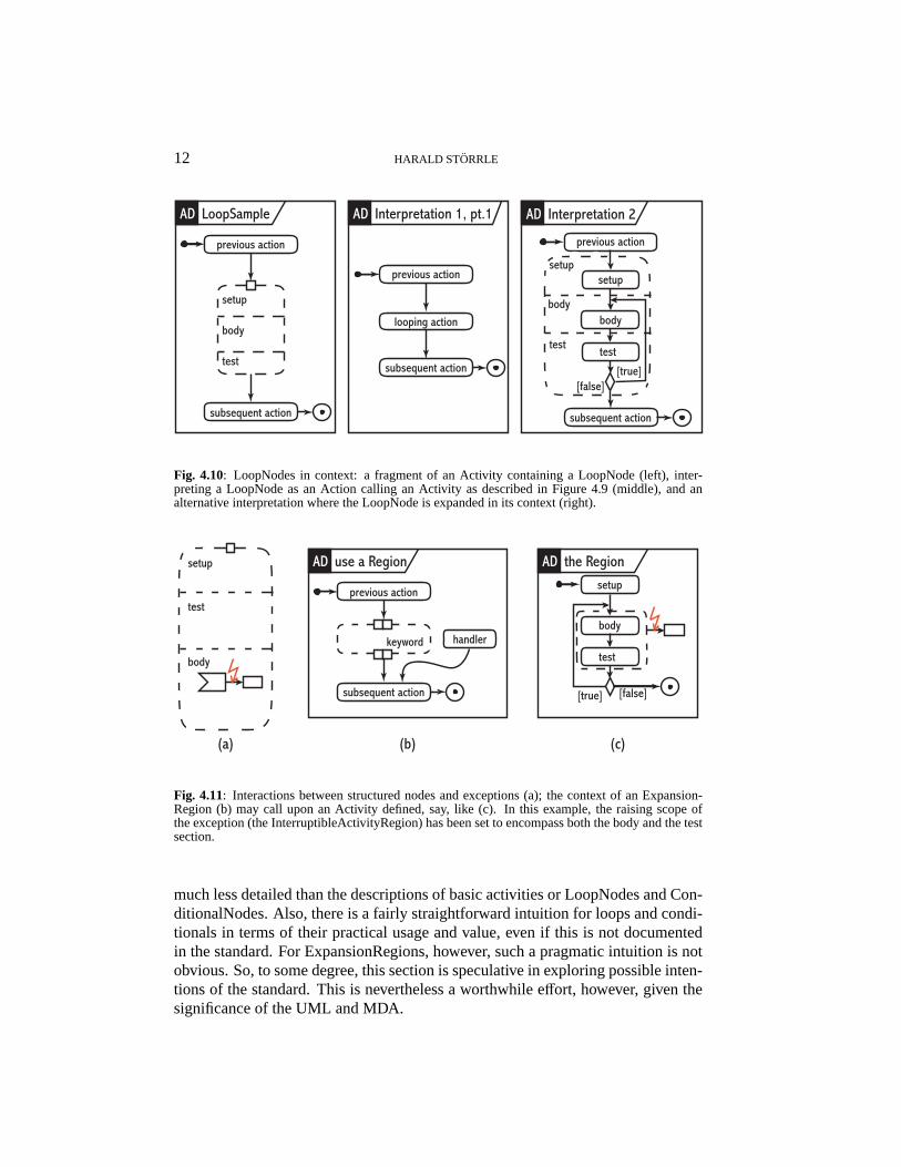
tunately, the meaning of the word “costructured” remains opaque. The standardgoes on by saying that “each section is a well-nested subregion of the activitywhose nodes follow any predecessors of the loop and precede any successors ofthe loop.” (cf. OMG [2003, p. 341]). This seems to indicate that a LoopNode isjust a kind of additional structure on top of an Activity. That is, the activity diagramfragment shown in Figure 4.10 (left) is identical to the Activity diagram fragmentof Figure 4.10 (right), and the LoopNode structure shown there has no meaning atall, and is just a kind of reading guide that overlays the structure of the Activity.But then, why are there LoopNodes in the first place?
Also, consider the interaction of loops with exceptions. A natural constructionone would expect to be admissible (and simple enough semantically) is the situa-tion shown in Figure 4.11 (a) and (b).4 What is the scope of the exception—is thebody section also an InterruptibleActivityRegion? Or should it be possible that theexception is raised in the test and/or setup, too, as suggested by Figure 4.11 (c)?
Actually, both situations make sense. So I propose to follow the interpretationshown in Figure 4.10 (b) where the LoopNode is a plain Action refined by theActivity of, say, Figure 4.9 (b). This node is now also the protected node of theexception. This way, it is possible to raise an exception anywhere in the loop. If thescope of the exception is supposed to be more restricted, the Activity that refinesthe “looping action” node must raise an exception.
5. ExpansionRegions
In this section, ExpansionRegions are explained. The description of Expansion-Regions in the UML standard exhibits far more errors and inconsistencies and is
4 On the syntax and semantics of exceptions in UML 2.0 activity diagrams, see Storrle [2004c].
12 HARALD STORRLE
test
setup
body
previous action
subsequent action
LoopSampleAD
previous action
subsequent action
looping action
Interpretation 1, pt.1AD
setup
body
[true]
previous action
subsequent action
test
setup
body
Interpretation 2AD
test
[false]
Fig. 4.10: LoopNodes in context: a fragment of an Activity containing a LoopNode (left), inter-preting a LoopNode as an Action calling an Activity as described in Figure 4.9 (middle), and analternative interpretation where the LoopNode is expanded in its context (right).
test
setup
body
(a) (b)
previous action
subsequent action
use a RegionAD
keyword handler
(c)
the RegionADsetup
body
[true] [false]
test
Fig. 4.11: Interactions between structured nodes and exceptions (a); the context of an Expansion-Region (b) may call upon an Activity defined, say, like (c). In this example, the raising scope ofthe exception (the InterruptibleActivityRegion) has been set to encompass both the body and the testsection.
much less detailed than the descriptions of basic activities or LoopNodes and Con-ditionalNodes. Also, there is a fairly straightforward intuition for loops and condi-tionals in terms of their practical usage and value, even if this is not documentedin the standard. For ExpansionRegions, however, such a pragmatic intuition is notobvious. So, to some degree, this section is speculative in exploring possible inten-tions of the standard. This is nevertheless a worthwhile effort, however, given thesignificance of the UML and MDA.

STRUCTURED NODES IN UML 2.0 ACTIVITIES 13
5.1 Intuition
ExpansionRegions are ActivityNodes that process collections of elements as a unit.The standard declares that when “an execution of an activity makes a token avail-able to the input of an ExpansionRegion, [it] consumes the token and begins exe-cution. The ExpansionRegion is executed once for each element in the collection”(cf. OMG [2003, p. 326]). In a way, thus, an ExpansionRegion can be viewed as akind of map-function from one collection to another.
Now consider an example (the standard does not provide one). In Figure 5.12,the running example from Figure 2.1 has been extended to cope with orders wherethe attribute goods is not just a single item of type Good but a Good collection. Forinstance, instead of ordering a single item, a whole batch might be ordered by onecustomer. While the administrative processing like general ordering procedure,invoicing, payment and so on are the same as for orders consisting of just one item,the actual production must now be executed once for each item in the batch. Thiscould be modeled explicitly, or one could use an ExpansionRegion for this purpose.
Orderfilled: Boolbilled: Boolpaid: Boolshipped: Boolgoods: Good collection
same (Order): Boolinit (Int): Order join (Order): Orderpay(): voidbundle(Good collection): void ship goods
receive order
fill order
close order
send invoice
receivepayment
{order.pay()}
{order.close()}
{reject}
[accepted]
:Order
{order.fill()}
produce goodsiterative
{order.goods}
{order.bundle(goods)}
OrderExampleCD OrderBehaviorAD
OrderBehaviorAD
Fig. 5.12: An example for using an ExpansionRegion in an activity diagram.
Please note the keyword in the lower right corner of the ExpansionRegion in Fig-ure 5.12. It indicates the mode of processing the arguments. It may be implementedin four different ways (not counting mixtures of these).
iterative that is, in a loop where each of the elements is treated in turn, butprocessing starts only on the complete set of arguments;

14 HARALD STORRLE
streaming is similar to iterative in that only one element is processed at once,but processing of the first element may start even though further ele-ments have not yet arrived;
parallel meaning that all elements are processed in lockstep, starting, proceed-ing, and ending together, irrespective of the actual time needed to pro-cess individual elements, and so possibly creating idle times;
concurrent is similar to parallel in that all arguments are treated potentially atthe same time, but independent of each other rather than in parallel.
Following the UML standard, it is possible to specify three of these variants bysetting the mode-attribute of ExpansionRegion. It may carry the values iterative,stream, and concurrent. Beware of the last mode setting, however: due to a spateof printing mistakes in the standard, the word parallel is used in all but one placeinstead of the word concurrent. The behavior explained is definitely concurrency,though, not parallelism: “the execution may happen in parallel, or overlapping intime, but they are not required to” (cf. OMG [2003, p. 326]). To achieve paral-lelism, the standard would have to specify the execution as “parallel in lockstep,beginning, proceeding, and ending simultaneously” or similar.
At this point, an important feature of Activities is encountered. The standardstates that “the expansion region is executed once for each element in the collection(or once per element position, if there aremultiple collections).” (cf. OMG [2003,p. 326, emphasis added]) This seems to imply that an Activity is a kind of dataflow-computer with different parameters flowing through it—similar to a Petri-net, infact5, and not like an individual run.
Unlike simple StructuredActivityNodes, ExpansionRegions can not be explainedeasily in terms of more elementary constructs. Thus, a semantics should be de-fined in terms of a more fundamental formalism, i.e., Petri-nets. In addition to thereasons given above, there is another reason why ExpansionRegions can not becovered by elementary Petri-nets: if there are several computations going on at thesame time, they must be isolated from each other to avoid unintended interactions.Thus, a macro-like expansion strategy, as has often been proposed for high-levelPetri-nets, is not the best choice here. In Storrle [2004b], this problem has alreadybeen solved silently by the very definition of procedural Petri-nets.
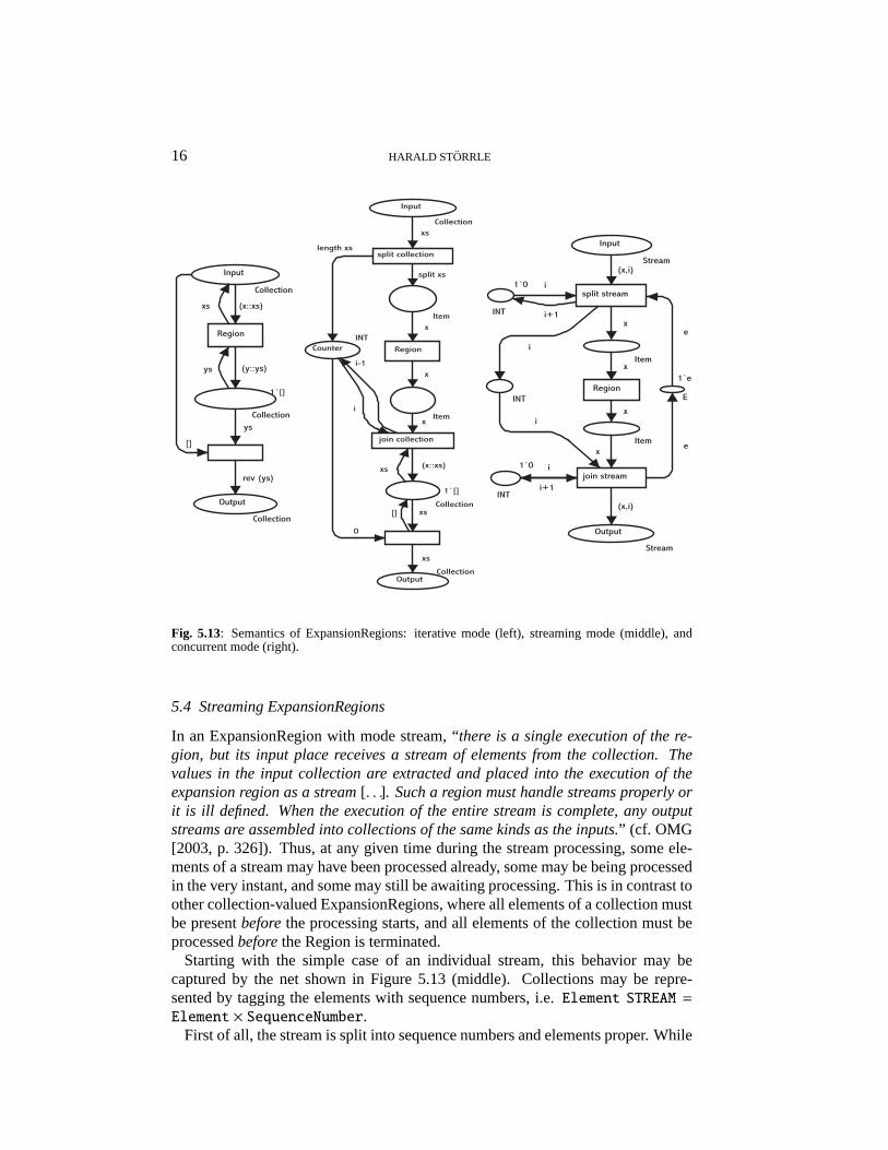
So, using the procedure call semantics we already discussed for LoopNodes andExpansionRegions, this problem is avoided altogether (details on the formalismare found in Storrle [2004c]). Thus, similar to the treatment of LoopNodes asproposed in Figure 4.10 (middle), ExpansionRegions should be translated as re-fined Actions (see Figure 4.11 b and c), where various calls to the same refine-ment transitions executes in its own state space. Depending on the mode of theExpansionRegion, different refinement nets must be used (see Figure 5.13). Whatthese refinement nets look like will be explained in the following sections for eachkind of ExpansionRegion.
5 Also, this raises again the question how well activity diagrams are suited for, say, workflow mod-eling, and whether Activities represent a workflow type/schema or an instance.
STRUCTURED NODES IN UML 2.0 ACTIVITIES 15
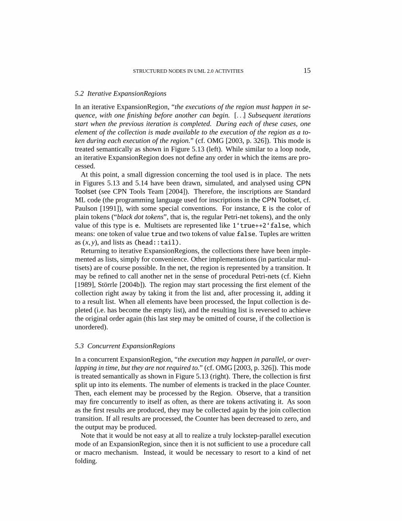
5.2 Iterative ExpansionRegions
In an iterative ExpansionRegion, “the executions of the region must happen in se-quence, with one finishing before another can begin.[. . .] Subsequent iterationsstart when the previous iteration is completed. During each of these cases, oneelement of the collection is made available to the execution of the region as a to-ken during each execution of the region.” (cf. OMG [2003, p. 326]). This mode istreated semantically as shown in Figure 5.13 (left). While similar to a loop node,an iterative ExpansionRegion does not define any order in which the items are pro-cessed.
At this point, a small digression concerning the tool used is in place. The netsin Figures 5.13 and 5.14 have been drawn, simulated, and analysed usingCPNToolset (see CPN Tools Team [2004]). Therefore, the inscriptions are StandardML code (the programming language used for inscriptions in theCPN Toolset, cf.Paulson [1991]), with some special conventions. For instance,E is the color ofplain tokens (“black dot tokens”, that is, the regular Petri-net tokens), and the onlyvalue of this type ise. Multisets are represented like1‘true++2‘false, whichmeans: one token of valuetrue and two tokens of valuefalse. Tuples are writtenas (x, y), and lists as(head::tail).
Returning to iterative ExpansionRegions, the collections there have been imple-mented as lists, simply for convenience. Other implementations (in particular mul-tisets) are of course possible. In the net, the region is represented by a transition. Itmay be refined to call another net in the sense of procedural Petri-nets (cf. Kiehn[1989], Storrle [2004b]). The region may start processing the first element of thecollection right away by taking it from the list and, after processing it, adding itto a result list. When all elements have been processed, the Input collection is de-pleted (i.e. has become the empty list), and the resulting list is reversed to achievethe original order again (this last step may be omitted of course, if the collection isunordered).
5.3 Concurrent ExpansionRegions
In a concurrent ExpansionRegion, “the execution may happen in parallel, or over-lapping in time, but they are not required to.” (cf. OMG [2003, p. 326]). This modeis treated semantically as shown in Figure 5.13 (right). There, the collection is firstsplit up into its elements. The number of elements is tracked in the place Counter.Then, each element may be processed by the Region. Observe, that a transitionmay fire concurrently to itself as often, as there are tokens activating it. As soonas the first results are produced, they may be collected again by the join collectiontransition. If all results are processed, the Counter has been decreased to zero, andthe output may be produced.
Note that it would be not easy at all to realize a truly lockstep-parallel executionmode of an ExpansionRegion, since then it is not sufficient to use a procedure callor macro mechanism. Instead, it would be necessary to resort to a kind of netfolding.
16 HARALD STORRLE
Input
Collection
Region
Collection
Output
Collection
(x::xs)
(y::ys)
ys
rev (ys)
ys
xs
[]
Input
Collection
CounterINT
Collection
1`[]
Item
Item
Region
split collection
join collection
xs
split xs
x
x
x
(x::xs)
length xs
i
i-1
0
xs
OutputCollection
xs
xs
[]
Input
Stream
INT
1`0
INT
INT
1`0
Output
Stream
split stream
join stream
Region
Item
Item
(x,i)
i
i
(x,i)
x
x
x
x
i
i
i+1
i+1
E
1`e
e
e
1`[]
Fig. 5.13: Semantics of ExpansionRegions: iterative mode (left), streaming mode (middle), andconcurrent mode (right).
5.4 Streaming ExpansionRegions
In an ExpansionRegion with mode stream, “there is a single execution of the re-gion, but its input place receives a stream of elements from the collection. Thevalues in the input collection are extracted and placed into the execution of theexpansion region as a stream[. . .]. Such a region must handle streams properly orit is ill defined. When the execution of the entire stream is complete, any outputstreams are assembled into collections of the same kinds as the inputs.” (cf. OMG[2003, p. 326]). Thus, at any given time during the stream processing, some ele-ments of a stream may have been processed already, some may be being processedin the very instant, and some may still be awaiting processing. This is in contrast toother collection-valued ExpansionRegions, where all elements of a collection mustbe presentbeforethe processing starts, and all elements of the collection must beprocessedbeforethe Region is terminated.
Starting with the simple case of an individual stream, this behavior may becaptured by the net shown in Figure 5.13 (middle). Collections may be repre-sented by tagging the elements with sequence numbers, i.e.Element STREAM =
Element × SequenceNumber.First of all, the stream is split into sequence numbers and elements proper. While
STRUCTURED NODES IN UML 2.0 ACTIVITIES 17
the element is processed by the Region, the sequence number is passed by. Thecomplement place ensures proper synchronisation.
The mappings provided in this and the two previous sections may be validatedagain usingCPN Toolset (see Figure 5.14).
6. Conclusion
6.1 Summary
In this paper, the concepts related to StructuredActivityNodes are examined.LoopNodes and ConditionalNodes may be defined as syntactic sugar. Expansion-Regions may be defined by mappings to high-level Petri-nets. Some problems con-cerning the concrete and abstract syntax and the semantics have been uncovered inthe standard (concrete syntax of Conditional- and LoopNodes, scope of exceptions,single/multiple inputs), and some possible solutions have been proposed.
There have been several proposals for semantics of activity diagrams, but mostof these aim at UML 1.x. For UML 2.0, there are only Barros and Gomes [2003]and Storrle [2004b, 2004a, 2004c] dealing with the semantics, and Bock [2003a,2003b, 2003c, 2004a, 2004b] dealing with some of constructs on an intuitive level.
6.2 Related work
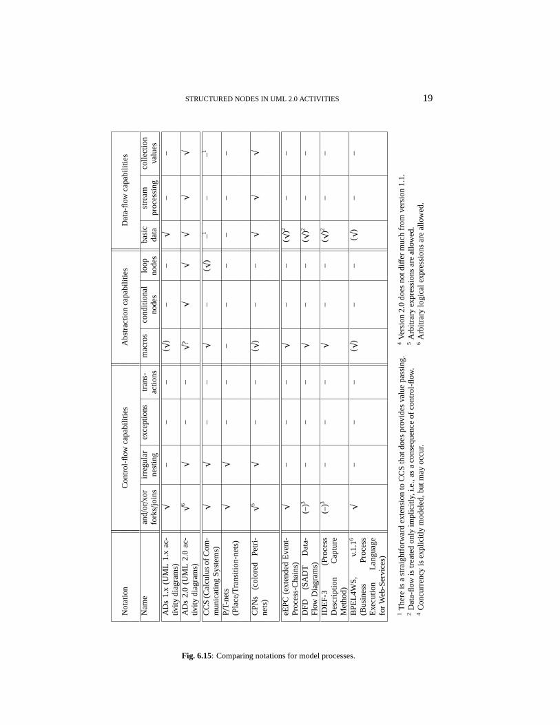
There are two kinds of related work that are to be considered. On the one hand,there are predecessors and relatives of activity diagrams, that is, all the other no-tations that server similar purposes. Table 6.15 shows a comparison of the expres-siveness of some of these notations.◦ UML The most obvious comparison is of course between the activity dia-
grams in the various UML versions (cf. OMG [1998] and OMG [2003] vs.OMG [2003]). While the basic constructs remain more or less unchanged,version 2.0 adds several powerful features, including exceptions, arbitraryfork/join-conditions, LoopNodes, ConditionalNodes, and different kinds ofExpansionRegions.
◦ formal methods The earliest notations for processes are P/T-nets (seeBaumgarten [1996],Murata [1989]). While exhibiting desirable and inter-esting theoretical properties, they have never quite reached industry. Highlevel nets like colored Petri-nets (CPNs, see Jensen [1992]) have increasedexpressive power, but have not caught on, despite a number of successfulcase studies. The same is true for other formal methods for concurrency likeProcess algebras (e.g., CCS, see Milner [1989]). They have the additionaldrawback of being a purely textual notation, thus lacking visual appeal.
◦ business processesIn business process modeling, (extended) Event-Process-Chains (eEPC) are very popular (cf. Kelleret al. [1991],Scheer [1995]), inparticular in conjunction with ERP packages such as SAP R/3. eEPCs andsimilar notations are now in widespread use, despite their limited expressive-ness, rather restricted tool-support, and the persistent lack of adequate formalfoundations.
18 HARALD STORRLE
Fig. 5.14: Validation of semantic mappings for ExpansionRegions usingCPN Toolset.
STRUCTURED NODES IN UML 2.0 ACTIVITIES 19
Not
atio
nC
ontr
ol-fl
owca
pabi
litie
sA
bstr
actio
nca
pabi
litie
sD
ata-
flow
capa
bilit
ies
Nam
ean
d/or/x
orirr
egul
arex
cept
ions
tran
s-m
acro
sco
nditi
onal
loop
basi
cst
ream
colle
ctio
nfo
rks/
join
sne
stin
gac
tions
node
sno
des
data
proc
essi
ngva
lues
AD
s1.
x(U
ML
1.x
ac-
tivity
diag
ram
s)
√–
––
(√)
––
√–
–
AD
s2.
0(U
ML
2.0
ac-
tivity
diag
ram
s)
√6
√–
–√
?√
√√
√√
CC
S(C
alcu
lus
ofC
om-
mun
icat
ing
Sys
tem
s)
√√
––
√–
(√)
–1–
–1
P/T-
nets
(Pla
ce/T
rans
ition
-net
s)
√√
––
––
––
––
CP
Ns
(col
ored
Pet
ri-ne
ts)
√5
√–
–(√
)–
–√
√√
eEP
C(e
xten
ded
Eve
nt-
Pro
cess
-Cha
ins)
√–
––
√–
–(√
)2–
–
DF
D(S
AD
TD
ata-
Flo
wD
iagr
ams)
(–)3
––
–√
––
(√)2
––
IDE
F-3
(Pro
cess
Des
crip
tion
Cap
ture
Met
hod)
(–)3
––
–√
––
(√)2
––
BP
EL4
WS
,v.
1.16
(Bus
ines
sP
roce
ssE
xecu
tion
Lang
uage
for
Web
-Ser
vice
s)
√–
––
(√)
––
(√)
––
1T
here
isa
stra
ight
forw
ard
exte
nsio
nto
CC
Sth
atdo
espr
ovid
esva
lue
pass
ing.
4Ve
rsio
n2.
0do
esno
tdiff
erm
uch
from
vers
ion
1.1.
2D
ata-
flow
istr
eate
don
lyim
plic
itly,
i.e.,
asa
cons
eque
nce
ofco
ntro
l-flow
.5
Arb
itrar
yex
pres
sion
sar
eal
low
ed.
4C
oncu
rren
cyis
expl
icitl
ym
odel
ed,b
utm
ayoc
cur.
6A
rbitr
ary
logi
cale
xpre
ssio
nsar
eal
low
ed.
Fig. 6.15: Comparing notations for model processes.
20 HARALD STORRLE
◦ general purposeAnother notation with a similar scope, if slightly more ori-ented towards IT applications rather than the domain as such are data-flowdiagrams (DFD, see Gane and Sarson [1979]) and IDEF-3 (see National In-stitute of Standards and Technologies [1993]). Both of these originate withthe structured methods of the 70’s and 80’s, and provide by and large similarexpressiveness as UML 1.x activity diagrams.
◦ Workflows On an even more detailed level, there are workflow descriptionlanguages that feed into workflow engines. As one representative, considerBPEL4WS (see Andrewset al. [5 May 2003]). Like CCS, BPEL4WS lacksan adequate graphical representation. It is conceivable, though, that activitydiagrams be used as a front-end for BPEL4WS.
Obviously, UML activity diagrams offer several new concepts and notations thatare not present in any of the traditional business process modeling languages. Ithas been argued that such a rich language is difficult to handle, and too powerfulfor many tasks or users. However, UML activity diagrams are intended as a nota-tion for modeling processes of all kinds, underlining the general idea of aunifiedmodeling language, i.e., one for all purposes and users. In practical applications,thus, the available expressive means may be tailored to fit the respective users. Forinstance, concepts like exceptions might be disallowed in an organisation for usein modeling business use cases.
On the other hand, there is a body of work concerning the semantics of UML ac-tivity diagrams. Since the UML standard has been written from scratch as far as ac-tivity diagrams are concerned, most of the previous work examining UML activitydiagrams (see Allweyer and Loos [1998], Apvrilleet al. [2001], Bolton and Davies[2000], Bolton and Davies [2000], Borgeret al. [2000], Dumas and ter Hofstede[2001], Eshuis [2002], Eshuis and Wieringa [2001], Eshuis and Wieringa [2001],Eshuis and Wieringa [2001], Eshuis and Wieringa [2002], Eshuis and Wieringa[2003], Gehrkeet al. [1998], Li et al. [2001], Petriu and Sun [2000], Pinheiro daSilva [2001], Rodrigues [2000]) has become obsolete. See Figure 6.16 for a com-parison.
In particular, structured nodes which have not been there in the UML 1.5 have notbeen addressed so far. Also, it seems that so far, only very little has been publishedon the UML 2.0 activity diagrams: Barros and Gomes [2003] examines expansionsand streaming in a intuitive way, focusing on shared input pins and some aspectsof streaming.
In a series of articles Bock [2003a, 2003b, 2003c, 2004a, 2004b], one of themain figures behind Activities in the UML 2.0 has tried to supplement the standardby a more elaborate description, still lacking a formal semantics, though. Whilerather instructive in many respects, important aspects are not covered, in particular,ExpansionRegions.
In a series of articles Storrle [2004b, 2004a, 2004c] I provide formal definitionsof the semantics of control-flow, procedure call, data-flow, and exceptions in UML2.0 Activities, respectively. This paper builds on the latter.
The most up-to-date account of the state of the discussion on the UML in generalis found in the OMG’s Issues-Database OMG [2004]. Currently, it seems as if the

STRUCTURED NODES IN UML 2.0 ACTIVITIES 21
auth
ors,
refe
renc
esU
ML
sem
antic
cont
rol
data
hier
arch
yex
cept
ions
stre
amin
gst
ruct
ured
rigor
vers
ion
dom
ain
flow
flow
node
s
Allw
eyer
and
Loos
[199
8]0.
9–
wf
√–
––
–lo
w
Apv
rille
etal
.[20
01]
1.x
LOT
OS
wf
––
––
–m
ediu
m
Bor
gere
tal.
[200
0]1.
xA
SM
wf
–√
––
–m
ediu
m
Bol
ton
and
Dav
ies
[200
0,20
00]
1.3
CS
Pw
f–
––
––
low
Esh
uis
[200
2],
1.x
algo
rithm
wf,
nwf
––
––
–hi
ghE
shui
san
dW
ierin
ga[2
001]
Esh
uis
and
Wie
ringa
[200
1,20
01]
1.x
LTS
wf,
nwf
––
––
–hi
gh
Geh
rkee
tal.
[199
8]1.
0P
Nw
f,nw
f(–
)–
––
–m
ediu
m
Pin
heiro
daS
ilva
[200
1]1.
xLO
TO
Sw
f,tim
e–
––
––
low
Rod
rigue
s[2
000]
1.x
FS
Pw
f–
––
––
low
Liet
al.[
2001
]1.
xLT
Sw
f(–
)–
––
–hi
gh
Sto
rrle
[200
4b]
2.0
PP
Nw
f,nw
f–
√–
––
high
Sto
rrle
[200
4a]
2.0
CP
Nw
f,nw
f√
––
––
high
Sto
rrle
[200
4c]
2.0
EC
PN
(wf,
nwf)
(√)
(√)
√–
–m
ediu
m
PN=
sim
ple
P/T-
Pet
ri-ne
tsE
CP
N=ex
cept
ion
colo
red
Pet
ri-ne
tsF
SP=
finite
stat
epr
oces
ses
PP
N=
proc
edur
alP
etri-
nets
LOT
OS=
Lang
uage
ofTe
mpo
ralO
rder
ing
Spe
cific
atio
nsLT
S=
labe
led
tran
sitio
nsy
stem
sC
PN=
colo
red
Pet
ri-ne
tsC
SP=
com
mun
icat
ing
sequ
entia
lpro
cess
esA
SM=
abst
ract
stat
em
achi
nes
Fig. 6.16: Comparative categorization of the previous work leading to this article (in column“control-flow”, wf means well-formed, and nwf means non well formed. The degree of rigor isapproximate, where a completely formal definition is high rigor, examples and some formalism ismedium, and mere text is low.
22 HARALD STORRLE
OMG actually makes a move towards formal semantics after all.
6.3 New questions
Building on this work, one may now turn to questions like what refinement andcomposition means for Activities, or how the new constructs work in the field,which subsets are suitable for which tasks, and whether there are any omissions.For instance, treatment of transactions is definitely an important issue, but is cur-rently not supported.
Also, it would be interesting to apply traditional complexity and size-measuresto activity diagrams. For instance, how does the replacement of explicit loops byloop nodes affect the cyclomatic complexity of an activity diagram.
Finally, the combination with other parts of the UML must be examined, in par-ticular the relationship to Interactions and StateMachines, whose natural semanticdomains must be related to Petri-nets. Also, examples soon become too complexfor manual treatment, and so tool-support is needed. In Storrle [2004a], I haveshown how standard Petri-net tools may be applied to verify properties of UML2.0 activity diagrams, using a Petri-net semantics.
References
A, T L, P. 1998. Process Orientation in UML through Integration ofEvent-Driven Process Chains. InInternational Workshop�UML�’98: Beyond the Notation.Ecole Superieure des Sciences Appliquees pour l’Ingenieur—Mulhouse, Universite de Haute-Alsace, 183–193.
A, T, C, F, D, H, G, Y, K, J, L-, F, L, K, R, D, S, D, T, S, T, I, W, S. 5 May 2003. Business Process Execution Language for Web Services(v1.1).
A, L, S-S, P, L, C., S, P, C, J-P.2001. A New UML Profile for Real-Time System Formal Dessigne and Validation. InProc.4th Intl. Conf. on the Unified Modeling Language (�UML� 2001), Number 2185 in LNCS.Springer Verlag, 287–301.
B, J P. G, Lı. 2003. Actions as Activities as Petri nets. InProc. Ws. CriticalSystems Development with UML , 129–135.
B, B. 1996. Petri-Netze. Grundlagen und Anwendungen.. Spektrum AkademischerVerlag, Heidelberg.
B, C. 2003a. UML 2 Activity and Action Models.J. Object Technology 2 , 4 (July/August),43–53.
B, C. 2003b. UML 2 Activity and Action Models: Actions.J. Object Technology 2 , 5(September/October), 41–56.
B, C. 2003c. UML 2 Activity and Action Models: Control Nodes.J. Object Technology2 , 6 (November/December), 7–22.
B, C. 2004a UML 2 Activity and Action Models: Object Nodes.J. Object Technology 3,1 (January/February), 27–41.
B, C. 2004b. UML 2 Activity and Action Models: Partitions.J. Object Technology 3, 7(July/August), 37–56.
B, C D, J. 2000. Activity graphs and processes. InProc. Intl. Conf. IntegratedFormal Methods (IFM), LNCS. Springer Verlag.
B, C D, J. 2000. On giving a behavioural semantics to activity graphs. InProc. Intl. Ws. Dynamic Behavior in UML Models: Semantic Questions. Technical ReportNo. 0006 of the Ludwig-Maximilians-Universitat, Munchen, Inst. f. Informatik , 17–22.

STRUCTURED NODES IN UML 2.0 ACTIVITIES 23
B, E, C, A, R, E. 2000. An ASM Semantics for UMLActivity Diagrams. InProc. 8th Intl. Conf. Algebraic Methodology and Software Technology(AMAST), Number 1816 in LNCS. Springer Verlag, 293–308.
CPN T T. 2004. CPN Tools Manual. Tech. report, Univ. of Aarhus.D, M H, A H.M. 2001. UML Activity Diagrams as a Workflow
Specification Language. InProc. 4th Intl. Conf. on the Unified Modeling Language (�UML�2001), Number 2185 in LNCS. Springer Verlag, 76–90.
E, H. 2002. Semantics and Verification of UML Activity Diagrams for Workflow Mod-elling. PhD thesis, CTIT, U. Twente.
E, R W, R. 2001. A formal semantics for UML Activity Diagrams - Formalis-ing workflow models. Tech. Report CTIT-01-04, U. Twente, Dept. of Computer Science.
E, R W, R. 2001. A Real-Time Execution Semantics for UML Activity Di-agrams. InProc. 4th Intl. Conf. Fundamental approaches to software engineering (FASE),Number 2029 in LNCS. Springer Verlag, 76–90.
E, R W, R. 2001. An Execution Algorithm for UML Activity Graphs. InProc.4th Intl. Conf. on the Unified Modeling Language (�UML� 2001), Number 2185 in LNCS.Springer Verlag, 47–61.
E, R W, R. 2002. Verification support for workflow design with UML activitygraphs. InProc. 24th Intl. Conf. on Software Engineering (ICSE). IEEE, 166–176.
E, R W, R. 2003. Comparing Petri Net and Activity Diagram Variantsfor Workflow Modelling - A Quest for Reactive Petri Nets. InPetri Net Technology forCommunication-Based Systems. DFG Research Group “Petri Net Technology”, 321–351.
G, C S, T. 1979.Structured Systems Analysis: Tools and Techniques. PrenticeHall.
G, T, G, U, W, H. 1998. The Dynamic Models of UML:Towards a Semantics and its Application in the Development Process. Tech. Report 11/98,Institut fur Informatik, Universitat Hildesheim.
G, M K, C, E. 2001. Proc. 4th Intl. Conf. on the Unified ModelingLanguage (�UML� 2001), Number 2185 in LNCS. Springer Verlag.
J, K. 1992.Coloured Petri Nets. Basic Concepts, Analysis Methods and Practical Use. Vol.I . EATCS Monographs on Theoretical Computer Science. Springer Verlag.
K, G., N, M, S, A-W. 1991. Semantische Prozessmodel-lierung auf der Grundlage Ereignisgesteuerte Prozessketten (EPK). Tech. Report 089, Institutfr Wirtschaftsinformatik, Uni Saarbrcken.
K, A. 1989.A Structuring Mechanism for Petri Nets. Dissertation, TU Munchen.L, X, C, M, P, Y, J, Z, G, Z. 2001. Timing Analysis of
UML Activity Diagrams. InProc. 4th Intl. Conf. on the Unified Modeling Language (�UML�2001), Number 2185 in LNCS. Springer Verlag, 62–75.
M, R. 1989.Communication and Concurrency. Prentice Hall.M, T. 1989. Petri Nets: Properties, Analysis and Applications.Proc. IEEE 77, (April),
541–580.N I S T. 1993. Integration Definition for Function Mod-
eling. Tech. report, Computer Systems Laboratory, NIST.OMG. 1998. OMG Unified Modeling Language Specification (version 1.3). Tech. report, Object
Management Group.OMG. 2003. OMG Unified Modeling Language Specification (adopted formal specification, version
1.5). Tech. report, Object Management Group.OMG. 2003. OMG Unified Modeling Language: Superstructure (final adopted spec, version 2.0).
Tech. report, Object Management Group.OMG. 2004. The OMG UML Issues Database. Tech. report, Object Management Group.P, L C. 1991.ML for the Working Programmer. Cambridge University Press.P, D C. S, Y. 2000. Consistent Behaviour Representation in Activity and Se-
quence Diagrams. InProc. 3rd Intl. Conf.�UML� 2000—Advancing the Standard , Number1939 in LNCS. Springer Verlag, 369–382.
P S, P. 2001. A proposal for a LOTOS-based semantics for UML. Tech. ReportUMCS-01-06-1, Dept. of Computer Science, U. Manchester.
24 HARALD STORRLE
R, G, K, A, R, B, S, B, W, R, E.2000. Proc. Intl. Ws. Dynamic Behavior in UML Models: Semantic Questions. TechnicalReport No. 0006 of the Ludwig-Maximilians-Universitat, Munchen, Inst. f. Informatik .
R, RW.S. 2000. Formalising UML Activity Diagrams using Finite State Processes.In Proc. Intl. Ws. Dynamic Behavior in UML Models: Semantic Questions. Technical ReportNo. 0006 of the Ludwig-Maximilians-Universitat, Munchen, Inst. f. Informatik , 92–98.
S, A-W. 1995. Business Process Engineering. Reference Models for IndustrialEnterprises. Springer Verlag.
S, H. 2003. Semantics of Interactions in UML 2.0. InHuman Centric ComputingLanguages and Environments. IEEE Computer Society, 129–136.
S, H. 2004a. Semantics and Verification of Data-Flow in UML 2.0 Activities. InProc.Intl. Ws. on Visual Languages and Formal Methods (VLFM’04). IEEE Press, 38–52.
S, H. 2004b. Semantics of Control-Flow in UML 2.0 Activities. InProc. IEEE Sympo-sium on Visual Languages and Human-Centric Computing (VL/HCC). Springer Verlag, 235–242.
S, H. 2004c. Semantics of Exceptions in UML 2.0 Activities. Tech. Report 0403,Ludwig-Maximilians-Universitat Munchen, Institut fur Informatik.
S, H. 2004d. Semantics of Expansion Nodes in UML 2.0 Activities. InProc. 2nd NordicWs. on UML, Modeling, Methods and Tools (NWUML’04).