Structured Connectivity Solutions Field Testing Guidelines ...
22
SYSTIMAX ® Solutions Structured Connectivity Solutions Field Testing Guidelines for Fiber-Optic Cabling Systems May 2016
Transcript of Structured Connectivity Solutions Field Testing Guidelines ...
SYSTIMAX® Solutions
Structured Connectivity Solutions Field Testing Guidelines for Fiber-Optic Cabling Systems
May 2016

TABLE OF CONTENTS
1. INTRODUCTION 1
2. PASSIVE LINK SEGMENTS 2
3. GENERAL TESTING GUIDELINES 2
4. ACCEPTABLE ATTENUATION VALUES 4
5. RELATIVE POWER MEASUREMENTS 5
6. TEST PROCEDURE FOR SINGLE-FIBER TEST EQUIPMENT 6
6.1. OVERVIEW 6
6.2. TEST CORD PERFORMANCE VERIFICATION 6
6.3. LINK SEGMENT TESTING 7
7. TEST PROCEDURE FOR MULTI-FIBER TEST EQUIPMENT 11
7.1. OVERVIEW 11
7.2. TEST CORD PERFORMANCE VERIFICATION 11
7.3. LINK SEGMENT TESTING 13
8. TIA AND ISO/IEC STANDARDS 14
9. TROUBLESHOOTING 15
9.1. CABLE PLANT DEFECT DETECTION AND RESOLUTION 15
9.2. TEST EQUIPMENT CHECKLIST 16
APPENDIX A: ENCIRCLED FLUX LAUNCH CONDITIONS 17
APPENDIX B: MEASUREMENT WORKSHEETS 18
1
1. Introduction The following guidelines describe CommScope’s recommended procedure for field testing multimode and singlemode cabling systems. CommScope only requires testing of link attenuation for Enterprise networks. While other fiber-optic cabling system parameters such as bandwidth are equally important, they are not normally adversely affected by the quality of the installation and therefore do not require field testing. This document describes how and where attenuation testing should be performed for Enterprise Systems, using both single-fiber and multi-fiber test equipments. This issue replaces the previous one dated February 2013. In addition, TIA-568-C.0 and its second addendum, TIA-568-C.0-2, provide standard requirements and guidelines for testing installed optical fiber cabling systems. Optical loss (link attenuation), length verification and polarity testing are defined therein as Tier 1 test ing, while OTDR testing is Tier 2 and an optional test. IMPORTANT NOTE FOR MULTIMODE FIBER TESTING The fiber optic industry has long understood the importance of a consistent launch condition for accurate and repeatable multimode measurements in both the field and the factory. This has led to mode conditioning of the launch cord attached to the light source. For multimode fiber testing in the field, this mode conditioner has traditionally been a mandrel around which the launch cord is wrapped. Standards have recently been updated to specify Encircled Flux (EF) launch conditions. These new requirements are defined in TIA-526-14-C (an adoption of IEC 61280-04-1 ed.2) and normatively referenced in TIA-568-C.0-2 (August 2012), ISO/IEC 11801 and ISO/IEC 14763-3. It is important to note that customers who require compliance to these standards also require the use of EF launch conditions for all multimode cabling attenuation tests. This change was driven by the recognition that loss budgets have diminished as data rates have increased, thus necessitating more precise measurements. CommScope strongly recommends the use of optical test equipment that provides an Encircled Flux–compliant launch condition, but at this time EF testing will not be a requirement for Partners requesting the warranty of SYSTIMAX® installations. However if a customer requires TIA adherence, CommScope will not waive the EF testing requirement. CommScope will update these testing requirements as standards and product offerings continue to evolve. Review Appendix A for more information on Encircled Flux.
2
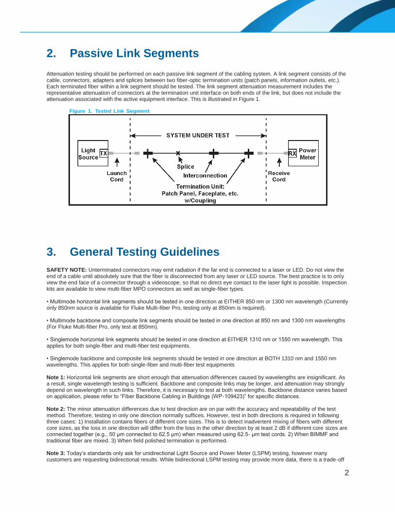
2. Passive Link Segments Attenuation testing should be performed on each passive link segment of the cabling system. A link segment consists of the cable, connectors, adapters and splices between two fiber-optic termination units (patch panels, information outlets, etc.). Each terminated fiber within a link segment should be tested. The link segment attenuation measurement includes the representative attenuation of connectors at the termination unit interface on both ends of the link, but does not include the attenuation associated with the active equipment interface. This is illustrated in Figure 1.
Figure 1. Tested Link Segment
3. General Testing Guidelines SAFETY NOTE: Unterminated connectors may emit radiation if the far end is connected to a laser or LED. Do not view the end of a cable until absolutely sure that the fiber is disconnected from any laser or LED source. The best practice is to only view the end face of a connector through a videoscope, so that no direct eye contact to the laser light is possible. Inspection kits are available to view multi-fiber MPO connectors as well as single-fiber types. • Multimode horizontal link segments should be tested in one direction at EITHER 850 nm or 1300 nm wavelength (Currently only 850nm source is available for Fluke Multi-fiber Pro, testing only at 850nm is required). • Multimode backbone and composite link segments should be tested in one direction at 850 nm and 1300 nm wavelengths (For Fluke Multi-fiber Pro, only test at 850nm). • Singlemode horizontal link segments should be tested in one direction at EITHER 1310 nm or 1550 nm wavelength. This applies for both single-fiber and multi-fiber test equipments. • Singlemode backbone and composite link segments should be tested in one direction at BOTH 1310 nm and 1550 nm wavelengths. This applies for both single-fiber and multi-fiber test equipments Note 1: Horizontal link segments are short enough that attenuation differences caused by wavelengths are insignificant. As a result, single wavelength testing is sufficient. Backbone and composite links may be longer, and attenuation may strongly depend on wavelength in such links. Therefore, it is necessary to test at both wavelengths. Backbone distance varies based on application, please refer to “Fiber Backbone Cabling in Buildings (WP-109423)” for specific distances. Note 2: The minor attenuation differences due to test direction are on par with the accuracy and repeatability of the test method. Therefore, testing in only one direction normally suffices. However, test in both directions is required in following three cases: 1) Installation contains fibers of different core sizes. This is to detect inadvertent mixing of fibers with different core sizes, as the loss in one direction will differ from the loss in the other direction by at least 2 dB if different core sizes are connected together (e.g., 50 μm connected to 62.5 μm) when measured using 62.5- μm test cords. 2) When BIMMF and traditional fiber are mixed. 3) When field polished termination is performed. Note 3: Today’s standards only ask for unidirectional Light Source and Power Meter (LSPM) testing, however many customers are requesting bidirectional results. While bidirectional LSPM testing may provide more data, there is a trade-off

3
with the extra time required and the additional opportunity for dirt and dust to be introduced during the testing process. Bidirectional test results are optional; if used, the direction with the higher loss measurement would be used to determine pass/fail for the link. CommScope recommends multimode field tests to be performed with the Encircled Flux launch condition as defined in TIA-526-14-C and IEC 61280-4-1 ed. 2. Defining a particular launch condition reduces measurement error and variability. This particular launch will produce field measurements that correlate well with component specifications. A mode conditioner device is recommended over the prior mandrel-wrapped cord method. Refer to Appendix A for more information. Note: When a mode conditioner device is not available, a high order mode loss (HOML) test can be performed to assess the launch condition of the test equipment and ensure it is in compliance per TIA-526-14-C. In compliance with TIA/EIA-526-14-C “Optical Power Loss Measurements of Installed Multimode Fiber Cable Plant”, IEC 61280-4-1 edition 2, “Fibre-Optic Communication Subsystem Test Procedure – Part 4-1: Installed cable plant – Multimode attenuation measurement”, TIA/EIA-526-7 “Measurement of Optical Power Loss of Installed Singlemode Fiber Cable Plant” and IEC 61280-4-2 edition 2, “Fibre-Optic Communication Subsystem Test Procedure – Part 4-2: Installed cable plant – Singlemode attenuation and optical return loss measurement”, the following information should be recorded during the test procedure: 1. Names of personnel conducting the test 2. Type of test equipment used (manufacturer, model, serial number and calibration date*) 3. Date test is being performed 4. Optical source wavelength, spectral width 5. Fiber identification 6. End point locations 7. Test direction 8. Reference power measurement (when not using a power meter with a Relative Power Measurement Mode) 9. Measured attenuation of the link segment 10. Acceptable link attenuation *Test equipment should be calibrated according to the test equipment manufacturer’s specifications. See Appendix B for sample measurement recording forms. IMPORTANT NOTE: Ensure that all connectors/modules are cleaned prior to mating test cords, trunk cables or patch cords. Contamination as small as 0.001 mm can block the fiber core generating strong back reflections (low Return Loss) and may affect attenuation (Insertion Loss). Mating a contaminated connector to a clean connector will result in poor performance and can transfer contamination and permanently damage the connection. CommScope recommends that fiber optic connectors are inspected with a microscope prior to mating. Please refer to the CommScope Fiber Optic Connector and Adapter Cleaning Procedures and the CommScope Fiber Optic Connector Cleaning and Inspection kit for more detailed information. Also refer to Section 9 in this document.
4
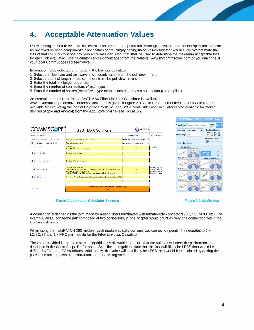
4. Acceptable Attenuation Values LSPM testing is used to evaluate the overall loss of an entire optical link. Although individual component specifications can be reviewed on each component’s specification sheet, simply adding these values together would likely overestimate the loss of that link. CommScope provides a link loss calculator that shall be used to determine the maximum acceptable loss for each link evaluated. This calculator can be downloaded from the website, www.mycommscope.com or you can consult your local CommScope representative. Information to be selected or entered in the link loss calculator: 1. Select the fiber type and test wavelength combination from the pull-down menu 2. Select the unit of length in feet or meters from the pull-down menu 3. Enter the total link length under test 4. Enter the number of connections of each type 5. Enter the number of splices (each Qwik type connections counts as a connection plus a splice). An example of the format for the SYSTIMAX Fiber LinkLoss Calculator is available at www.mycommscope.com/Resources/Calculators/ is given in Figure 2-1. A similar version of the LinkLoss Calculator is available for evaluating the loss of Uniprise® systems. The SYSTIMAX Link Loss Calculator is also available for mobile devices (Apple and Android) from the App Store on-line (see Figure 2-2).
Figure 2-1 LinkLoss Calculator Example Figure 2-2 Mobile App
A connection is defined as the joint made by mating fibers terminated with remate-able connectors (LC, SC, MPO, etc). For example, an LC connector pair composed of two connectors, in one adapter would count as only one connection within the link loss calculator. When using the InstaPATCH 360 module, each module actually contains two connection points. This equates to 1 x LC/SC/ST and 1 x MPO per module for the Fiber LinkLoss Calculator. The value provided is the maximum acceptable loss allowable to ensure that the solution will meet the performance as described in the CommScope Performance Specifications guides. Note that this loss will likely be LESS than would be defined by TIA and IEC standards. Additionally, this value will also likely be LESS than would be calculated by adding the potential maximum loss of all individual components together.

5
5. Relative Power Measurements If the power meter supports measurements relative to a reference measurement (in units of dB), select this mode because such readings do not necessitate manual calculation. If the meter does not have a Relative Power Measurement mode, perform the following calculation to determine attenuation: Pref is the power level of the reference measurement. Psum is the power reading of the device under test. • If Psum and Pref are in the same logarithmic units (dBm, dBμ, etc.): Attenuation (dB) = | Pref – Psum | • If Psum and Pref are in the same linear units (Watts, milliWatts (mW), mircoWatts (μW)): Attenuation (dB) = | 10 x LOG10 [Pref/Psum] | Important Note: Both light source and power meter must be stabilized prior to measurement. The amount of time required depends on the temperature difference between unit storage space and test operation space. Allow a minimum of 5 minutes (could be up to 10+ minutes) of stabilization time before proceeding with test. Please refer to specific equipment operational guides for more details. Caution: Stable reference power levels are critical to the accuracy of subsequent attenuation measurements. Instability may arise from at least two common causes: battery health and mechanical changes at the connection to the source. Ensure the battery is in good operating condition and fully charged in both the source and power meter. Avoid disturbing the connection in any way from the source to the launch cord after the reference measurement. Disturbances include disconnection, lateral side-loading, and axial tension. Any of these disturbances is cause for making a new reference measurement. The chances of encountering these disturbances may be minimized by securing the launch cord to the source test set by means of tape or cable tie applied at the launch conditioning device (described later). CommScope fiber solutions require the use of power meters that accept plugs of the type used to terminate the cabling system under test. CommScope recommends all multimode launch cord performance verifications and link attenuation measurements to be performed with the Encircled Flux launch condition as defined in TIA-526-14-C and IEC 61280-4-1 ed. 2. See Appendix A for more information. Note: For multimode systems, HOML method can be used per TIA-526-14-C if unable to secure a nearfield scanner or mode conditioner for EF verification/compliance. Caution: Laser light sources, including Vertical Cavity Surface Emitting Lasers (VCSELs), cannot meet the minimum spectral width requirements defined by TIA-526-14-C for LSPMs. Therefore, laser and VCSEL sources are not accepted for certifying multimode fiber systems. LED sources are acceptable for certifying multimode fiber systems. CommScope fiber solutions require all singlemode performance verifications and link attenuation measurements to be performed with a launch test cord containing a single loop < 30mm (1.2 inches) in diameter to suppress multimode propagation. This loop may be created by either wrapping the cord around a mandrel or in free space by securing the cord to itself.
6
6. Test Procedure for Single-Fiber Test Equipment
6.1. Overview 1. Obtain a reference power level (see Section 5). 2. Verify test cord performance (see Section 6.2) 3. Measure link power throughput (see Section 6.3). 4. Record link attenuation (see Section 5 and Appendix B). Two worksheets in Appendix B may be used for recording measurement information. The first is for use with power meters that display absolute power levels without a selectable reference. The second is for power meters that display power levels relative to a measured reference level. Of course, today most test sets will allow the user to record the data within the test units to access electronically later. Electronic recording is the preferred method of recordkeeping.
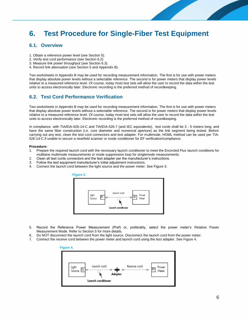
6.2. Test Cord Performance Verification Two worksheets in Appendix B may be used for recording measurement information. The first is for use with power meters that display absolute power levels without a selectable reference. The second is for power meters that display power levels relative to a measured reference level. Of course, today most test sets will allow the user to record the data within the test units to access electronically later. Electronic recording is the preferred method of recordkeeping. In compliance with TIA/EIA-526-14-C and TIA/EIA-526-7 (and IEC equivalents), test cords shall be 3 - 5 meters long, and have the same fiber construction (i.e. core diameter and numerical aperture) as the link segment being tested. Before carrying out any test, clean the test cord connectors and test adapter. For multimode, HOML method can be used per TIA-526-14-C if unable to secure a nearfield scanner or mode conditioner for EF verification/compliance. Procedure: 1. Prepare the required launch cord with the necessary launch conditioner to meet the Encircled Flux launch conditions for
multilane multimode measurements or mode suppression loop for singlemode measurements. 2. Clean all test cords connectors and the test adapter per the manufacturer’s instructions. 3. Follow the test equipment manufacturer’s initial adjustment instructions. 4. Connect the launch cord between the light source and the power meter. See Figure 3.
Figure 3.
5. Record the Reference Power Measurement (Pref) or, preferably, select the power meter’s Relative Power
Measurement Mode. Refer to Section 5 for more details. 6. Do NOT disconnect the launch cord from the light source. Disconnect the launch cord from the power meter. 7. Connect the receive cord between the power meter and launch cord using the test adapter. See Figure 4.
Figure 4.

7
8. Record the Power Measurement (Psum). Perform the calculations given in Section 5 if not using Relative Power Measurement mode. This measurement provides the attenuation of the receive cord cable (very minimal) plus the connection between the launch and receive cords. The measured attenuation must be less than or equal to the corresponding value given in Table 1. Unacceptable attenuation measurements may be attributable to either of the test cords. Examine each cord with a portable video scope, and clean, polish, or replace if necessary.
9. Flip the ends of the receive cord so that the end originally connected to the power meter is now connected to the adapter, and the end originally connected to the adapter is now connected to the power meter.
10. Record the new Power Measurement (Psum). Perform the calculations given in Section 5 if not using Relative Power Measurement Mode. The attenuation must be less than or equal to the corresponding value found in Table 1. If both measurements are found to be less than or equal to the values found in Table 1, the receive cord is acceptable for testing purposes.
11. Reverse the launch and receive cords, and repeat this test procedure from the beginning to verify the performance of the launch cord. Remember to remove the existing launch conditioner or loop from the former launch cord and apply the same to new launch cord (formerly the receive cord).
Table 1. Acceptable Test Cord Attenuation
Fiber Type
Connection Type Between Test Cords
ST or SC LC MPO
62.5 µm Multimode 0.30dB Max 0.20dB Max 0.2dB Max
LazrSPEED 50 µm 0.30dB Max 0.20dB Max 0.2dB Max
OptiSPEED and TeraSpeed 9 µm 0.55dB Max 0.30dB Max 0.3dB Max
6.3. Link Segment Testing
6.3.1 Case 1: Matching Connector Types Between Test Equipment and Cabling In order to include all connections in the measurement, the One-cord Reference Method specified in TIA/EIA-526-14-C (for multimode fibers) and TIA/EIA-526-7 (for singlemode fibers) shall be used to test each link segment. In order to perform the one cord reference method, it is necessary that the receptacle on the power meter accept the plug type used on the cabling. Procedure: 1. Use verified test cords by following the procedure in Section 6.2. 2. Repeat procedure 1-4 from Section 6.2. 3. Record the Reference Power Measurement (Pref) or, preferably, select the power meter’s Relative Power
Measurement Mode and set the reading to 0.0 dB. 4. Do NOT disconnect the launch cord from the light source. Disconnect the launch cord from the power meter. Connect
the receive cord between the power meter and launch cord using the test adapter (see Figure 4). Verify that the connector loss is at or below the value shown in Table 1.
5. Separate the launch cord from the receive cord and connect to the ends of the system under test as shown in Figure 5. DO NOT disturb the connection to the source.
Figure 5.
8
6. Record the power measurement (Psum) by either performing the calculations given in Section 5 or, if the meter is in relative power mode, by reading the value directly from the power meter. This measurement provides the attenuation of the link segment cable(s), splice(s) and connections, including the connections on its ends. If the measurement value is less than or equal to the value calculated using the LinkLoss calculator (see Section 4), the link segment attenuation is acceptable. If not acceptable see Section 9 for troubleshooting guidance.
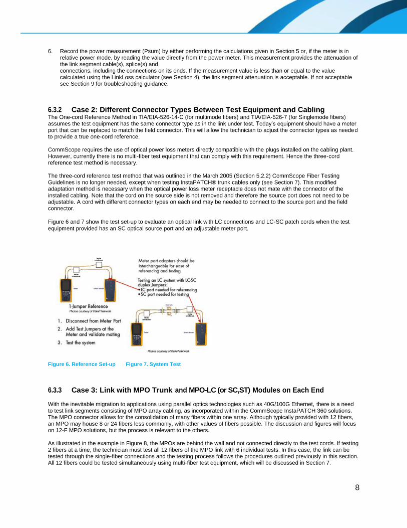
6.3.2 Case 2: Different Connector Types Between Test Equipment and Cabling The One-cord Reference Method in TIA/EIA-526-14-C (for multimode fibers) and TIA/EIA-526-7 (for Singlemode fibers) assumes the test equipment has the same connector type as in the link under test. Today’s equipment should have a meter port that can be replaced to match the field connector. This will allow the technician to adjust the connector types as needed to provide a true one-cord reference.
CommScope requires the use of optical power loss meters directly compatible with the plugs installed on the cabling plant. However, currently there is no multi-fiber test equipment that can comply with this requirement. Hence the three-cord reference test method is necessary. The three-cord reference test method that was outlined in the March 2005 (Section 5.2.2) CommScope Fiber Testing Guidelines is no longer needed, except when testing InstaPATCH® trunk cables only (see Section 7). This modified adaptation method is necessary when the optical power loss meter receptacle does not mate with the connector of the installed cabling. Note that the cord on the source side is not removed and therefore the source port does not need to be adjustable. A cord with different connector types on each end may be needed to connect to the source port and the field connector.
Figure 6 and 7 show the test set-up to evaluate an optical link with LC connections and LC-SC patch cords when the test
equipment provided has an SC optical source port and an adjustable meter port.
Figure 6. Reference Set-up Figure 7. System Test
6.3.3 Case 3: Link with MPO Trunk and MPO-LC (or SC,ST) Modules on Each End With the inevitable migration to applications using parallel optics technologies such as 40G/100G Ethernet, there is a need to test link segments consisting of MPO array cabling, as incorporated within the CommScope InstaPATCH 360 solutions. The MPO connector allows for the consolidation of many fibers within one array. Although typically provided with 12 fibers, an MPO may house 8 or 24 fibers less commonly, with other values of fibers possible. The discussion and figures will focus on 12-F MPO solutions, but the process is relevant to the others. As illustrated in the example in Figure 8, the MPOs are behind the wall and not connected directly to the test cords. If testing 2 fibers at a time, the technician must test all 12 fibers of the MPO link with 6 individual tests. In this case, the link can be tested through the single-fiber connections and the testing process follows the procedures outlined previously in this section. All 12 fibers could be tested simultaneously using multi-fiber test equipment, which will be discussed in Section 7.

9
Figure 8
Each MPO to LC (or SC, ST) module counts as two connections because the MPO and single-fiber connections make separate connections. When selecting number of connections within the LinkLoss calculator, add one connection for both the single-fiber and MPO connector for each module. In the test shown in Figure 8 above, there are two MPO connections and two LC connections. An example of how the LinkLoss calculator is used to determine the maximum loss for this link is show in Figure 9-1 and Figure 9-2.
Figure 9-1 LinkLoss Calculator Example Figure 9-2 Mobile App
In contrast, use of an MPO to single-fiber fanout cord (Figure 10) in place of a module will only count as one MPO connection because the single-fiber connector will be plugged directly into the electronics.
Figure 10. MPO-LC harnesses may take the place of MPO-LC modules and LC duplex patch cords

10
6.3.4 Case 4: MPO Trunk Link
In this case, there are no single-fiber connectors with which to attach traditional single-fiber test cords. In laboratory or factory settings, there would be test equipment available that could directly attach to the MPO trunk cable. This requires 12 output sources and either 12 input ports or an MPO port with a very wide area detector to accept the light from all 12 (or 24 fibers).This set-up is impractical for field-testing. CommScope recommends testing MPO trunks with multi-fiber test equipment (Fluke Multi-fiber Pro) that accepts MPO connectors, allowing it to test all 12 fibers in the MPO trunk simultaneously. Detailed procedure for such test will be outlined in Section 7. When multi-fiber test equipment is not available, follow procedure in this section to test with the traditional single-fiber type tester. To perform the MPO trunk link test, the technician should use an MPO to LC fanout cord (See Figure 10) to separate the MPO trunk into single-fiber channels. Because of the additional fanout cords, a three cord reference method is required to offset the additional loss of the test connections. The basic steps for performing field attenuation measurements of an MPO trunk are: 1. Verify test cord performance (see Section 6.2). 2. Obtain a reference power level with the series of three cords in place per the diagram on the top right of Figure 11. 3. Remove the middle patch cord and add a verified reference grade MPO-LC fanout test cord on each side. The fanout
cords can be verified by ensuring the resulting power level does not exceed the values achieved in step 2 by more than 0.20dB.
4. Insert the MPO trunk in-between the two MPO-LC fanout cords and measure the loss at the first LC per the diagram in the lower left corner of Figure 11.
5. Record and measure the loss at the second LC and continue to the last connection. Figure 11. MPO Trunk Testing with Single-Fiber Test Equipment

11
7. Test Procedure for Multi-fiber Test Equipment
7.1. Overview 1. Obtain a reference power level (see Section 5). 2. Verify test cord performance (see Section 7.2) 3. Measure link power throughput (see Section 7.3). 4. Record link attenuation (see Section 5 and Appendix B). Two worksheets in Appendix B may be used for recording measurement information. The first is for use with power meters that display absolute power levels without a selectable reference. The second is for power meters that display power levels relative to a measured reference level. Of course, today most test sets will allow the user to record the data within the test units to access electronically later. Electronic recording is the preferred method of recordkeeping. The following sections focus on Fluke MultiFiber Pro tester, which accepts Male MPO connection at the source and power meter. Testing methods may be adjusted for other test equipments that accept Female MPO connections.
7.2. Test Cord Performance Verification To preserve the integrity of the source bulkhead, a stationary launch cord is recommended to reduce connects and disconnects to minimize damage. A launch extension cord serves the purpose of gender conversion without the need of replacing the launch cord to properly mate with the test link. EF compliance shall be verified at the end of launch cord, excluding the launch extension cord. In compliance with TIA/EIA-526-14-C and TIA/EIA-526-7 (and IEC equivalents), test cords shall be 3 - 5 meters
long, and have the same fiber construction (i.e. core diameter and numerical aperture) as the link segment being
tested. Before carrying out any test, clean the test cord connectors and test adapter. For multimode, HOML method
can be used per TIA-526-14-C if unable to secure a nearfield scanner or mode conditioner for EF
verification/compliance.
All reference-grade cords are tested by the manufacturer, with test data provided. CommScope highly recommends verifying the quality of all required test cords prior to link testing.
Required cords:
Cord Description
Minimum QTY
Female-Male Large Core Test Lead
1
Male-Male Large Core Test Lead
1
Male-Male Cord
2
Female-Male Cord
2
Female-Female Cord
1
7.2.1 Female-Male Test Cord Verification 1. Prepare the required launch cord with the necessary launch conditioner to meet the Encircled Flux launch conditions for
multimode measurements or mode suppression loop for Singlemode measurements. 2. Clean all test cords connectors and the test adapter per the manufacturer’s instructions. 3. Follow the test equipment manufacturer’s initial adjustment instructions. 4. Set up reference channel per Figure 12. Record the Reference Power Measurement (Pref) or, preferably, select the
power meter’s Relative Power Measurement Mode and set the reading to 0.0dB. Refer to Section 5 for more details.

12
Figure 12
5. Do NOT disturb the connection at the light source. Disconnect the launch cord from the large core test lead. 6. Insert the Female-Male Device Under Test (DUT) between the launch cord and the large core test lead. Record the new
Power Measurement (Psum). Perform the calculations given in Section 5 if not using Relative Power Measurement Mode. Record the attenuation, and it must be less than or equal to the corresponding value found in Table 1. This step completes the verification of the Female-Male test cord.
7.2.2 Male-Male Test Cord Verification 1. Prepare the required launch cords with the necessary launch conditioner to meet the Encircled Flux launch
conditions for multimode measurements or mode suppression loop for Singlemode measurements.
2. Clean all test cords connectors and the test adapter per the manufacturer’s instructions. 3. Follow the test equipment manufacturer’s initial adjustment instructions. 4. Set up reference channel per Figure 13. Record the Reference Power Measurement (Pref) or, preferably, select the
power meter’s Relative Power Measurement Mode and set the reading to 0.0dB. Refer to Section 5 for more details.
Figure 13
5. Do NOT disturb the connection at the light source. Remove the large core test lead. 6. Insert the Male-Male DUT between the launch cord and power meter. Record the new Power Measurement (Psum).
Perform the calculations given in Section 5 if not using Relative Power Measurement Mode. Record the attenuation, which must be less than or equal to the corresponding value found in Table 1.
7. Reverse the order of Male-Male DUT. Record the new Power Measurement (Psum). Perform the calculations given in Section 5 if not using Relative Power Measurement Mode. Record the attenuation, which must be less than or equal to the corresponding value found in Table 1.
7.2.3 Female-Female Test Cord Verification 1. Prepare the required launch cord with the necessary launch conditioner to meet the Encircled Flux launch
conditions or multimode measurements or mode suppression loop for Singlemode measurements.
2. Clean all test cords connectors and the test adapter per the manufacturer’s instructions. 3. Follow the test equipment manufacturer’s initial adjustment instructions. 4. Set up reference channel per Figure 14. Record the Reference Power Measurement (Pref) or, preferably, select the
power meter’s Relative Power Measurement Mode and set the reading to 0.0dB. Refer to Section 5 for more details.

13
Figure 14
5. Do NOT disturb the connection at the light source. Disconnect the launch cord from power meter. 6. Insert the Female-Female DUT and a verified Male-Male large core test lead between the launch cord and power meter.
Record the new Power Measurement (Psum). Perform the calculations given in Section 5 if not using Relative Power Measurement Mode. This attenuation must be less than or equal to the corresponding value found in Table 1.
7. Reverse the order of Female-Female DUT. Record the new Power Measurement (Psum). Perform the calculations given in Section 5 if not using Relative Power Measurement Mode. Record the attenuation, which must be less than or equal to the corresponding value found in Table 1.
7.3. Link Segment Testing Procedure: 1. Use verified reference cords by following the procedure in Section 7.2. 2. Prepare the required launch cord with the necessary launch conditioner for multimode
measurements or mode suppression loop for Singlemode measurements. 3. Clean the test cord connectors. 4. Follow the test equipment manufacturer’s initial set-up instructions. 5. Set up corresponding reference channel for each DUT. Refer to Figure 15.
Figure 15
6. Record the Reference Power Measurement (Pref) or, preferably, select the power meter’s Relative Power
Measurement Mode and set the reading to 0.0 dB. 7. DO NOT disturb the connection to the source. Disconnect at breakpoint and insert DUT and verified reference cord if
specified. 8. Record the power measurement (Psum) by either performing the calculations given in Section 5 or, if the meter is in
relative power mode, by reading the value directly from the power meter. This measurement provides the attenuation of the link segment cable(s), splice(s) and connections, including the connections on its ends. If the measurement value is less than or equal to the value calculated using the LinkLoss calculator (see Section 4), the link segment attenuation is acceptable. If not acceptable see Section 9 for troubleshooting guidance. Note: When using the LinkLoss calculator, ensure all measured connections are accounted for. For example, in the Female-Female DUT setup, the measured link attenuation must be compared against LinkLoss result of two MPO connections (one at breakpoint and second one between DUT and verified reference cord). In the Female-Male DUT setup, there are two MPO connections. In the Male-Male DUT, three MPO connections must be accounted for.
14
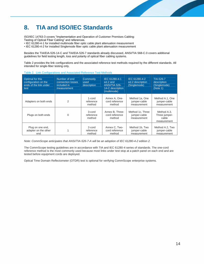
8. TIA and ISO/IEC Standards ISO/IEC 14763-3 covers “Implementation and Operation of Customer Premises Cabling: Testing of Optical Fiber Cabling” and references. • IEC 61280-4-1 for installed multimode fiber optic cable plant attenuation measurement • IEC 61280-4-2 for installed Singlemode fiber optic cable plant attenuation measurement Besides the TIA/EIA-526-14-C and TIA/EIA-526-7 standards already discussed, ANSI/TIA 568-C.0 covers additional guidelines for field testing length, loss and polarity of optical fiber cabling systems. Table 2 provides the link configurations and the associated reference test methods required by the different standards. All intended for single-fiber testing only. Table 2. Link Configurations and Associated Reference Test Methods Optimal for this configuration on the ends of the link under test
Number of end connection losses included in measurement
Commonly used description
IEC 61280-4-1 ed.2 and ANSI/TIA 526-14-C description (multimode)
IEC 61280-4-2 ed.2 description (Singlemode)
TIA-526-7 description (Singlemode) (Note 1)
Adapters on both ends
2
1-cord
reference method
Annex A, One-cord reference
method
Method 1a, One
jumper-cable measurement
Method A.1, One
jumper-cable measurement
Plugs on both ends
0
3-cord
reference method
Annex B, Three-cord reference
method
Method 1c, Three
jumper-cable measurement
Method A.3,
Three jumper-cable
measurement
Plug on one end,
adapter on the other end
1
2-cord
reference method
Annex C, Two-cord reference
method
Method 1b, Two
jumper-cable measurement
Method A.2, Two
jumper-cable measurement
Note: CommScope anticipates that ANSI/TIA-526-7-A will be an adoption of IEC 61280-4-2 edition 2. The CommScope testing guidelines are in accordance with TIA and IEC 61280-4 series of standards. The one-cord reference method is the most commonly used because most links under test stop at a patch panel on each end and are tested before equipment cords are deployed. Optical Time Domain Reflectometer (OTDR) test is optional for verifying CommScope enterprise systems.

15
9. Troubleshooting Link attenuation exceeding expectations may arise from several reasons. These include contamination, defects in the
cable plant, or improper test equipment usage. MPO solutions are particularly susceptible to contamination because of
the number of fibers, number of connections, and tight loss budgets. Frequent cleaning may be required.
9.1. Cable Plant Defect Detection and Resolution Contamination is the most common cause of optical loss within connections. For multimode and Singlemode cabling
the test cords and the ports under test should be clean and free of damage in accordance with IEC-61300-3-35. Check
connector end-faces for dirt and defects (see Table 3, Figures 16 & 17, and check link segment for broken fiber, poor
splices and tight bends.
Table 3.
Possible Cause Resolution
Adhesive bead left on the tip of a connector Examine connectors with a portable microscope and re-polish if necessary
Poorly polished connectors (see Figure 17) Examine connectors with a portable microscope and re-polish if necessary
Dirty connectors and/or adapters (see Figure 16) Examine connections and clean per manufacturer’s instructions
Broken fiber Identify break with a Visible Fault Locator or OTDR
and splice fiber or replace cable
Poor mechanical or fusion splices Identify poor splices with a Visible Fault Locator or
OTDR and re-splice if necessary
Excessively tight bends in the cabling
Identify tight bends by inspection or with a
Visible Fault Locator or OTDR and increase
the bend radius above minimum specifications
Patch cord does not match the fiber type (compare
jacket color and print statement) of the behind-the-
wall cabling
Replace test leads to match BTW cabling. Reset the reference and retest.
Figure 16. Dirty Connectors (Pictures courtesy of Fluke Networks)
Figure 17.
16
9.2. Test Equipment Checklist
Check Test Cord Conformance
Follow Section 6.2 and 7.2 to verify that the performance of test cords used conform to the values given in
Table 1.
Check Light Source Conformance
Ensure the source and launch cord combination meets launch condition specifications and the source
meets requirements for center wavelength and spectral width according to the standards referenced
within Section 3 and Appendix A.
Check Reference Level Stability
Ensure battery operated equipment batteries are in good condition with sufficient charge. Ensure that the
connection of launch cord to the light source is not disturbed after the reference level measurement.
Disturbances include disconnection and reconnection, lateral or axial stresses such as tugging, bumping the
connector, or bending the cordage. Any of these may introduce measurement errors.

17
Appendix A: Encircled Flux Launch Conditions IEC 61280-4-1 ed.2 and ANSI/TIA-526-14-C define a precision launch condition using a metric called Encircled Flux. This metric was established to reduce the measurement variability that is often observed between different test sets due to variations in the launch condition. Reducing this variability is important because loss budgets have become smaller as data rates have increased. Previously defined CPR-plus-mandrel-wrap prescriptions are incapable of assuring sufficiently small variability between test sets. Encircled Flux compliance is determined using a near-field imaging instrument and analysis software that measures the light distribution at the output end of a test launch cord when transmitting light from the intended test source. Although it is possible to produce a compliant native launch at the output port of the source, a mode conditioning device is typically required between the light source port and the launch test cord output to create a compliant condition. Reference grade launch cords are generally required to meet the launch specifications. Reference grade cords and launch conditioning devices may be available from the test set manufacturer. Following the test set manufacturer's recommendations should produce a compliant launch condition without necessitating actual near-field image verification in the field. Figure 18 illustrates the use of such mode conditioning devices applied near the output of the sources in a bidirectional test.
Figure 18
A High Order Mode Loss (HOML) test can be performed to qualify source and test lead should the launch condition of source and test lead be unknown, and a mode conditioner/launch analyzer is not available. This test should be performed per the guidance of ANSI-TIA-526-14-C. The foreword in this document provides background and guidance to performing the test. Also required is a mandrel as defined in the above referenced document and known good reference test cords. CommScope recommends the use of CommScope's supplied test cords. Test Reference Cords are available from Commscope in various configurations and can be ordered through Commscope customer service.
18
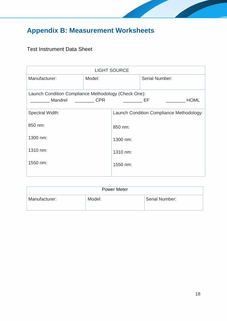
Appendix B: Measurement Worksheets
Test Instrument Data Sheet
LIGHT SOURCE
Manufacturer: Model: Serial Number:
Launch Condition Compliance Methodology (Check One):
Mandrel CPR EF HOML
Spectral Width: 850 nm:
1300 nm:
1310 nm:
1550 nm:
Launch Condition Compliance Methodology: 850 nm:
1300 nm:
1310 nm:
1550 nm:
Power Meter
Manufacturer: Model: Serial Number:
19
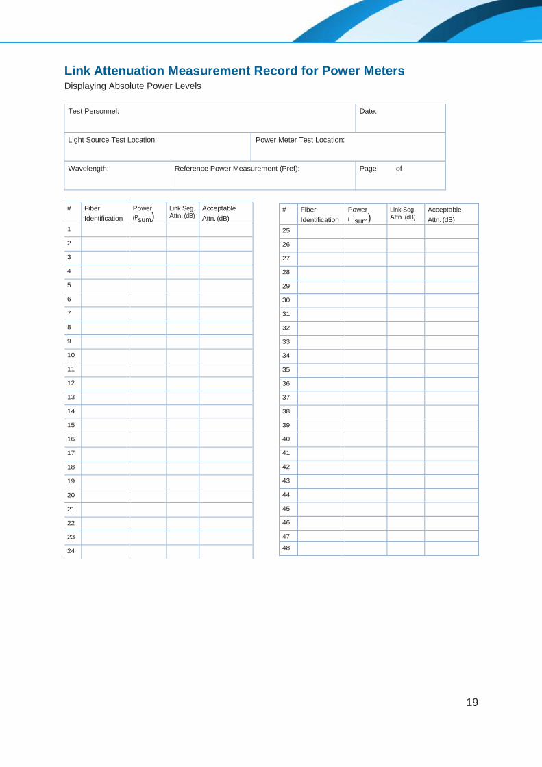
Link Attenuation Measurement Record for Power Meters Displaying Absolute Power Levels
Test Personnel: Date:
Light Source Test Location: Power Meter Test Location:
Wavelength: Reference Power Measurement (Pref): Page of
# Fiber
Identification
Power
(Psum)
Link Seg. Attn. (dB)
Acceptable
Attn. (dB)
1 2 3 4 5 6 7 8 9 10 11 12 13 14 15 16 17 18 19 20 21 22 23 24
# Fiber
Identification
Power
( Psum)
Link Seg. Attn. (dB)
Acceptable
Attn. (dB)
25 26 27 28 29 30 31 32 33 34 35 36 37 38 39 40 41 42 43 44 45 46 47 48
20
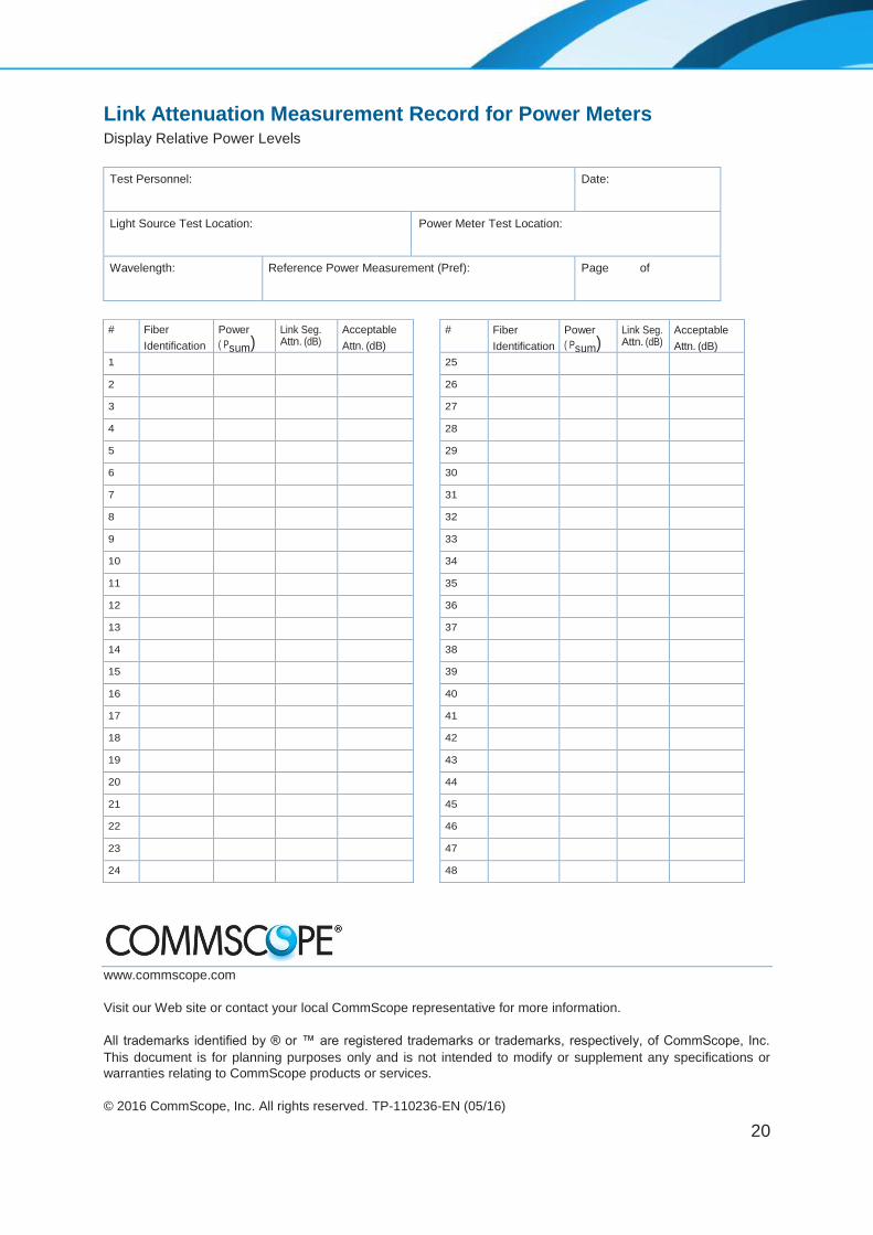
Link Attenuation Measurement Record for Power Meters Display Relative Power Levels
Test Personnel: Date:
Light Source Test Location: Power Meter Test Location:
Wavelength: Reference Power Measurement (Pref): Page of
www.commscope.com
Visit our Web site or contact your local CommScope representative for more information.
All trademarks identified by ® or ™ are registered trademarks or trademarks, respectively, of CommScope, Inc.
This document is for planning purposes only and is not intended to modify or supplement any specifications or
warranties relating to CommScope products or services.
© 2016 CommScope, Inc. All rights reserved. TP-110236-EN (05/16)
# Fiber
Identification
Power
( Psum)
Link Seg. Attn. (dB)
Acceptable
Attn. (dB)
1 2 3 4 5 6 7 8 9 10 11 12 13 14 15 16 17 18 19 20 21 22 23 24
# Fiber
Identification
Power
( Psum)
Link Seg. Attn. (dB)
Acceptable
Attn. (dB)
25 26 27 28 29 30 31 32 33 34 35 36 37 38 39 40 41 42 43 44 45 46 47 48