STRUCTURE AND MAGNETIC PROPERTIES OF ULTRA-THIN MAGNETIC LAYERS This work supported by ONR/DARPA...
16
STRUCTURE AND MAGNETIC STRUCTURE AND MAGNETIC PROPERTIES OF ULTRA-THIN PROPERTIES OF ULTRA-THIN MAGNETIC LAYERS MAGNETIC LAYERS This work supported by ONR/DARPA N00014-02-01-06 Justin M. Shaw Optical Sciences Center, University of Arizona, Tucson epartment of Physics and Astronomy, Arizona State University, Tempe Sungkyun Park Los Alamos National Laboratory Sukmock Lee Department of Physics, Inha University, Inchon, 402-751, Korea Charles M. Falco Optical Sciences Center, University of Arizona, Tucson
-
Upload
chastity-weaver -
Category
Documents
-
view
214 -
download
0
Transcript of STRUCTURE AND MAGNETIC PROPERTIES OF ULTRA-THIN MAGNETIC LAYERS This work supported by ONR/DARPA...

STRUCTURE AND MAGNETIC STRUCTURE AND MAGNETIC PROPERTIES OF ULTRA-THIN PROPERTIES OF ULTRA-THIN
MAGNETIC LAYERSMAGNETIC LAYERS
This work supported by ONR/DARPA N00014-02-01-0627
Justin M. ShawOptical Sciences Center, University of Arizona, Tucson
Department of Physics and Astronomy, Arizona State University, Tempe
Sungkyun ParkLos Alamos National Laboratory
Sukmock LeeDepartment of Physics, Inha University, Inchon, 402-751, Korea
Charles M. FalcoOptical Sciences Center, University of Arizona, Tucson

Outline of TalkOutline of Talk
• Introduction and Motivation;
• Sample Growth
•Annealed Fe layers on GaAs(001);
• Description of Spin-waves and Brillouin Light
Scattering (BLS);
• Results;
• Summary.

Introduction and MotivationIntroduction and Motivation
•Why Fe LAYERS ON GaAs?
• Spin injection has been demonstrated in Fe on GaAs;
• High quality BCC Fe layers can be easily grown on GaAs aFe/aGaAs = 1/2 (1.4% mismatch);
• These properties make Fe on GaAs(001) a candidate for FM metal-semiconductor contacts in spintronic devices;

Spintronics: What and Why?Spintronics: What and Why?
We want to exploit the spin degree of freedom in electrons.
Simple ‘Spin-Valve’spin injection “valve”
non-FMnon-FM FMFM
M M
non-FM
non-FMnon-FM FMFM
M M
non-FM
CurrentOut
CURRENT
NoCurrentOut
• Lower power;
• Higher speeds;
• Non-Volatile Memory;
• Quantum
Computing;
Spin is a quantum state.

Molecular Beam Epitaxy (MBE)
Growth Pbase= 4 x 10–11 TorrAnalysis Pbase= 3 x 10–11 Torr

Sample GrowthSample Growth
•SUBSTRATE PREPARATION;
•1 keV Ar+ at 600 °C;
•Streaky 4×6 surface;
•Fe DEPOSITION (15 Å);•Knudsen cell (0.088 Å/s);
•Tsubstrate = 30–35 °C;• ANNEALED (150–350 °C for 10
min.);
•OVERLAYER (Al );•E-beam evaporation;•Thickness = 20–90 Å.
GaAs(001)
15 Å Fe
50Å Al
Sample Structure
[110]
Al overlayer
We deposited all samples in a Perkin-Elmer 4-chamber MBE system with a base pressure of ~5 x 10–11 Torr
[110]

Spin-waves (Magnons)Spin-waves (Magnons)
• Spins (magnetic moments) oscillate slightly about their equilibrium position;
• Electron spins interact via exchange (short range) and dipole-dipole (long range);
Ferromagnetic crystals form quantized “spin-waves”.
From Kittel “Intro to Solid State Physics”

Inte
nsi
ty (
cou
nts
)
Spin Wave Frequency Shift (GHz)
Brillouin Light Scattering (BLS)Brillouin Light Scattering (BLS)

Annealing Temperature Dependence on Annealing Temperature Dependence on the Saturation Fieldthe Saturation Field
• Saturation fields are given by the minima in the spinwave frequencies along the hard axis;
• Saturation field changes behavior at Tanneal~ 225 °C.
0 50 100 150 200 250 3000.0
0.2
0.4
0.6
0.8
1.0
1.2
1.4
Sa
tura
tion
Fie
ld (
kOe
)
Annealing Temperature (°C)0 1 2 3 4 5 6
0
5
10
15
20
25
30
Sp
inw
ave
Fre
qu
en
cy (
GH
z)
Magnetic Field (kOe)
RT Fe Annealed 200°C
Location of minima
H=0 H Hsat
MspontaneosM M

Anisotropy Dependence of TAnisotropy Dependence of Tannealanneal
Magnetic Field = 3kOe
0 45 90 135 180 225 270 315 36015
20
25
Spi
nwav
eF
requ
ency
(G
Hz)
Azimuthal Angle (deg.)
300°C
275°C
250°C
225°C
200°C
150°C
RT0 45 90 135 180 225 270 315 360
15
20
25
Spi
nwav
eF
requ
ency
(G
Hz)
Azimuthal Angle (deg.)
0 45 90 135 180 225 270 315 36015
20
25
0 45 90 135 180 225 270 315 36015
20
25
Spi
nwav
eF
requ
ency
(G
Hz)
Azimuthal Angle (deg.)
300°C
275°C
250°C
225°C
200°C
150°C
RT
300°C
275°C
250°C
225°C
200°C
150°C
RT
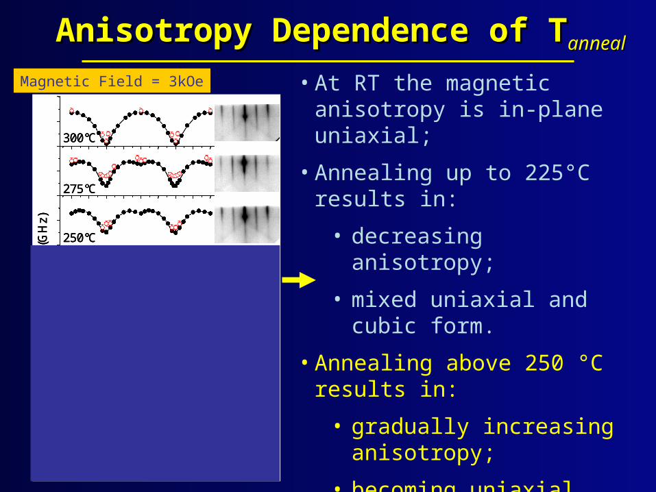
• At RT the magnetic anisotropy is in-plane uniaxial;
• Annealing up to 225°C results in:
• decreasing anisotropy;
• mixed uniaxial and cubic form.
• Annealing above 250 °C results in:
• gradually increasing anisotropy;
• becoming uniaxial again at 300 °C;
• the onset of a second mode.

Anisotropy Dependence of TAnisotropy Dependence of Tannealanneal
Magnetic Field = 3kOe
0 45 90 135 180 225 270 315 36015
20
25
Spi
nwav
eF
requ
ency
(G
Hz)
Azimuthal Angle (deg.)
300°C
275°C
250°C
225°C
200°C
150°C
RT0 45 90 135 180 225 270 315 360
15
20
25
Spi
nwav
eF
requ
ency
(G
Hz)
Azimuthal Angle (deg.)
0 45 90 135 180 225 270 315 36015
20
25
0 45 90 135 180 225 270 315 36015
20
25
Spi
nwav
eF
requ
ency
(G
Hz)
Azimuthal Angle (deg.)
300°C
275°C
250°C
225°C
200°C
150°C
RT
300°C
275°C
250°C
225°C
200°C
150°C
RT
• At RT the magnetic anisotropy is in-plane uniaxial;
• Annealing up to 225°C results in:
• decreasing anisotropy;
• mixed uniaxial and cubic form.
• Annealing above 250 °C results in:
• gradually increasing anisotropy;
• becoming uniaxial again at 300 °C;
• the onset of a second mode.

-20 0 20100
104
108
1012
1016
1020
Nor
mal
ized
Yie
ld
Frequency Shift (GHz)
90°
100°
110°
120°
135°
150°
160°
170°
180°
hard axis
easy axis0 45 90 135 180 225 270 315 360
15
20
25
Sp
inw
ave
Fre
qu
ency
(G
Hz)
Azimuthal Angle (deg.)
15 Å Fe Annealed 10 min. 275 °C
Additional Spinwave ModeAdditional Spinwave Mode• An additional spinwave mode develops for annealing
temperatures at or above 250 °C;
• This new mode is present only near a <110> direction (easy and hard axes).

Magneto-Optical Kerr Effect Magneto-Optical Kerr Effect (MOKE)(MOKE)
-400 -200 0 200 400
Ker
r E
llipt
icity
(ar
b. u
nit)
Magnetic Field (Oe)
RT
150 °C
200 °C
225 °C
250 °C
275 °C
300 °C
0 50 100 150 200 250 3000
50
100
150
200
250
300
Annealing Temperature (°C)
Co
erc
ivity
(O
e)
0.0
0.2
0.4
0.6
0.8
1.0
1.2
1.4
Sa
tura
tion
Fie
ld (kO
e)
• Coercivity increases rapidly for annealing temperatures above 225 °C.

Scanning Tunneling Microscopy (1 Scanning Tunneling Microscopy (1 μμm × 1 m × 1 μμm )m )
• Rectangular pits faceted along <110> directions form for annealing temperatures between 200 °C and 250 °C;
• X-ray Reflectometry 16% increase in Fe thickness for 300 °C anneal.
[110
]
[110
]
[110
]
[110
]
RT FeRMS roughness =0.890 ±0.02 nm
200 °C Anneal0.940 ±0.05 nm
250 °C Anneal0.883 ±0.04 nm
300 °C Anneal0.887 ±0.01 nm
(terraces: =0.484 ±0.07 nm)
400×400 nm

SummarySummary
•Ultra-thin ferromagnetic layers interfaced with semiconductors are critical to future Spintronic technology;
•Magnetic properties can be studied with high sensisitivity using BLS;
•The form and magnitude of the magnetic anisotropy is highly dependent on annealing temperature;
•Magnetic and structural changes occur at annealing temperatures at ~ 225 °C.