STRUCTURE AND DYNAMICS OF CRYOGENIC …mpj1001/papers/CST_Candel_Juniper_2006.pdf · research...
34
This article was downloaded by: [University of Cambridge] On: 02 January 2012, At: 08:13 Publisher: Taylor & Francis Informa Ltd Registered in England and Wales Registered Number: 1072954 Registered office: Mortimer House, 37-41 Mortimer Street, London W1T 3JH, UK Combustion Science and Technology Publication details, including instructions for authors and subscription information: http://www.tandfonline.com/loi/gcst20 STRUCTURE AND DYNAMICS OF CRYOGENIC FLAMES AT SUPERCRITICAL PRESSURE S. CANDEL* a , M. JUNIPER† a , G. SINGLA a , P. SCOUFLAIRE a & C. ROLON a a EM2C Laboratory, CNRS, Ecole Centrale Paris, France Available online: 25 Jan 2007 To cite this article: S. CANDEL*, M. JUNIPER†, G. SINGLA, P. SCOUFLAIRE & C. ROLON (2006): STRUCTURE AND DYNAMICS OF CRYOGENIC FLAMES AT SUPERCRITICAL PRESSURE, Combustion Science and Technology, 178:1-3, 161-192 To link to this article: http://dx.doi.org/10.1080/00102200500292530 PLEASE SCROLL DOWN FOR ARTICLE Full terms and conditions of use: http://www.tandfonline.com/page/terms- and-conditions This article may be used for research, teaching, and private study purposes. Any substantial or systematic reproduction, redistribution, reselling, loan, sub-licensing, systematic supply, or distribution in any form to anyone is expressly forbidden. The publisher does not give any warranty express or implied or make any representation that the contents will be complete or accurate or up to date. The accuracy of any instructions, formulae, and drug doses should be independently verified with primary sources. The publisher shall not be liable for any loss, actions, claims, proceedings, demand, or costs or damages
Transcript of STRUCTURE AND DYNAMICS OF CRYOGENIC …mpj1001/papers/CST_Candel_Juniper_2006.pdf · research...

This article was downloaded by: [University of Cambridge]On: 02 January 2012, At: 08:13Publisher: Taylor & FrancisInforma Ltd Registered in England and Wales Registered Number: 1072954Registered office: Mortimer House, 37-41 Mortimer Street, London W1T 3JH,UK
Combustion Science andTechnologyPublication details, including instructions forauthors and subscription information:http://www.tandfonline.com/loi/gcst20
STRUCTURE AND DYNAMICSOF CRYOGENIC FLAMES ATSUPERCRITICAL PRESSURES. CANDEL* a , M. JUNIPER† a , G. SINGLA a , P.SCOUFLAIRE a & C. ROLON aa EM2C Laboratory, CNRS, Ecole Centrale Paris,France
Available online: 25 Jan 2007
To cite this article: S. CANDEL*, M. JUNIPER†, G. SINGLA, P. SCOUFLAIRE & C.ROLON (2006): STRUCTURE AND DYNAMICS OF CRYOGENIC FLAMES AT SUPERCRITICALPRESSURE, Combustion Science and Technology, 178:1-3, 161-192
To link to this article: http://dx.doi.org/10.1080/00102200500292530
PLEASE SCROLL DOWN FOR ARTICLE
Full terms and conditions of use: http://www.tandfonline.com/page/terms-and-conditions
This article may be used for research, teaching, and private study purposes.Any substantial or systematic reproduction, redistribution, reselling, loan,sub-licensing, systematic supply, or distribution in any form to anyone isexpressly forbidden.
The publisher does not give any warranty express or implied or make anyrepresentation that the contents will be complete or accurate or up todate. The accuracy of any instructions, formulae, and drug doses should beindependently verified with primary sources. The publisher shall not be liablefor any loss, actions, claims, proceedings, demand, or costs or damages

whatsoever or howsoever caused arising directly or indirectly in connectionwith or arising out of the use of this material.
Dow
nloa
ded
by [
Uni
vers
ity o
f C
ambr
idge
] at
08:
13 0
2 Ja
nuar
y 20
12

STRUCTURE AND DYNAMICS OF CRYOGENIC
FLAMES AT SUPERCRITICAL PRESSURE
S. CANDEL*M. JUNIPERy
G. SINGLAP. SCOUFLAIREC. ROLON
EM2C Laboratory, CNRS, Ecole Centrale Paris, France
A detailed understanding of liquid propellant combustion is neces-
sary for the development of improved and more reliable propulsion
systems. This article describes experimental investigations aimed at
providing such a fundamental basis for design and engineering of
combustion components. It reports recent applications of imaging
techniques to cryogenic combustion at high pressure. The flame
structure is investigated in the transcritical range where the pressure
exceeds the critical pressure of oxygen ðp > pcðO2 ¼ 5:04MPaÞÞ butthe temperature of the injected liquid oxygen is below its critical
value ðTO2< TcðO2Þ ¼ 154KÞ. Data obtained from imaging of OH�
radicals emission, CH� radicals emission in the case of LOx=GCH4
flames and backlighting provide a detailed view of the flame struc-
ture for a set of injection conditions. The data may be used to guide
numerical modelling of transcritical flames and the theoretical and
numerical analysis of the stabilization process. Calculations of the
flame edge are used to illustrate this aspect. Results obtained may
also be employed to devise engineering modelling tools and
Received 23 July 2004; accepted 26 May 2005.
We wish to thank CNES, Snecma and CNRS for their continuous support of our work
in rocket propulsion. The assistance of the ‘‘Mascotte’’ team of Onera under the leadership
of Lucien Vingert and Mohamed Habiballah is gratefully acknowledged.
*Also with Institut Universitaire de France.yPresent Address: Engineering Department, Cambridge University.
Address correspondence to [email protected]
Combust. Sci. and Tech., 178: 161–192, 2006
Copyright Q Taylor & Francis LLC
ISSN: 0010-2202 print/1563-521X online
DOI: 10.1080/00102200500292530
161
Dow
nloa
ded
by [
Uni
vers
ity o
f C
ambr
idge
] at
08:
13 0
2 Ja
nuar
y 20
12
methodologies for component development aimed at improved
efficiency and augmented reliability.
Keywords: cryogenic combustion, flame stabilization, transcritical
injection
INTRODUCTION
Progress in liquid rocket propulsion technology during the second half of
the 20th century has allowed extensive commercial utilization of space
and a continuous growth of the launching market for telecommunications
and earth observation satellites. Developments in space transportation
systems have initially relied on accumulated experience from full scale
testing, engineering analysis and application of basic combustion princi-
ples. In this context, research carried out during the last fifteen years has
brought new insights on the processes controlling combustion in high
performance rocket motors. Detailed experiments have provided a stream
of data allowing design improvement and optimization. The data have
been used to assist modelling efforts and validate numerical simulation
tools. These, in turn, will allow a renewal of design methodologies for
improving engine components and augmenting their service life.
Cryogenic combustion investigations described in this article are con-
cerned with physical processes occurring in high-pressure chambers. The
research effort focuses on combustion of liquid propellants, which are
stored at low temperatures and require an external ignition to initiate the
chemical reaction. Cryogenic reactants, such as liquid oxygen and hydro-
gen, are used in high performance propulsion systems. Examples include
the Vulcain motor of the Ariane 5 first stage and the Space Shuttle main
engines (SSME), which typically operate at pressures in excess of 10MPa.
While early research into liquid rocket motors relied heavily on full
scale testing with some model scale experiments but with limited diagnos-
tic and data acquisition capabilities, the recent effort has exploited new
model scale facilities and a set of optical and laser diagnostics to gather
information on the process. The state of the art some 40 years ago is well
synthesized in the textbook of Barrere et al. (1960). Systematic tests
carried out on a wide variety of injection devices led to rapid adoption
of certain injection configurations (Burick, 1972, 1973; Gill, 1978; Haarje
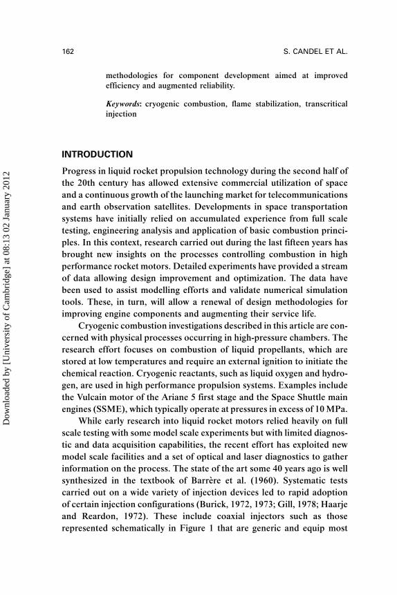
and Reardon, 1972). These include coaxial injectors such as those
represented schematically in Figure 1 that are generic and equip most
162 S. CANDEL ET AL.
Dow
nloa
ded
by [
Uni
vers
ity o
f C
ambr
idge
] at
08:
13 0
2 Ja
nuar
y 20
12
high-performance cryogenic engines. While the engineering know-how in
practical design has become substantial as a result of successive develop-
ments and accumulation of test results, fundamental scientific questions
relating to the physical processes at work in the chamber have remained
unanswered until recently. These mainly relate to transients following
ignition, flame propagation and spreading, the mechanism of flame
stabilization, factors governing flame length and conversion efficiency,
accurate estimation of heat transfer to the chamber walls and injection
backplane, sensitivity to impulsive perturbations, combustion dynamics,
and triggering of high frequency combustion instabilities.
An understanding of the flame structure is prerequisite to the solution
of many technical problems. This question has been difficult to tackle
because of the harsh conditions prevailing in the chamber and the dif-
ficulty of managing an optical access to the combustion region. Rocket
engines release powers of several GW—the equivalent of a few large
nuclear power plants—all within volumes of only a fraction of a cubic
meter and at temperatures in excess of 3000K. The power density reaches
50 to 100GWm�3 while the chamber pressure is in the 10 to 20MPa
range. Even model scale testing is highly energetic and should be carried
out at elevated pressures. Early experiments were also limited by sensor
performance, data acquisition equipment, and processing devices. Much
of the technological developments were therefore carried out without a
detailed understanding of the parameters controlling the structure of
the reactive flow and the dynamics of ignition and flame spreading during
the engine start. While models or numerical simulation tools could not
reproduce the complexity of the physical situation, engineering had to
deal with many difficult problems including: (1) The definition of a
Figure 1. Coaxial injectors of the type used in rocket motors. Liquid oxygen flows through
the central tube and gaseous hydrogen or methane through the annular passage. Left, the
oxygen tube is set flush with the hydrogen channel. Right, the oxygen tube is recessed.
CRYOGENIC FLAMES AT SUPERCRITICAL PRESSURE 163
Dow
nloa
ded
by [
Uni
vers
ity o
f C
ambr
idge
] at
08:
13 0
2 Ja
nuar
y 20
12
sequence ensuring a smooth ignition transient leading to a stable nominal
operation; (2) The sizing of injection elements and thrust chamber
providing the required efficiency; (3) Reduction of low frequency instabil-
ities involving the feed line and chamber dynamics; and (4) Suppression
of high frequency instabilities associated with the resonant coupling of
combustion and chamber eigenmodes. Many spectacular failures were
associated with dynamical phenomena and the related increase in heat
transfer to the walls often leading to chamber burnout.
The scientific analysis of cryogenic combustion essentially began
during the latter part of the twentieth century and these investigations
have benefitted from advances in laser diagnostics, digital imaging cam-
eras, experimental instrumentation, and high-speed digital data acqui-
sition. Research facilities such as the University of Pennsylvania rocket
propulsion test bed, Mascotte developed by Onera and P8 at DLR were
made available during the same period and could be exploited for hot
fire investigations under realistic injection conditions. In this general
context, research has focused on the following items:
. Processes controlling liquid jet breakup, atomization, and mixing;
. Spray vaporization and combustion;
. Stabilization and flame spread near the injection backplane;
. Experimental diagnostics applicable to cryogenic flames under high-
pressure conditions;
. Effect of pressure and transcritical phenomena.
Theoretical and numerical modelling efforts have also been carried
out in parallel to integrate knowledge from experiments and advance
engineering design methods.
This article reviews some of the more recent results of experimental
investigations of high-pressure cryogenic combustion. Other data are
available in the previous literature (see Candel et al., 1998; Herding
et al., 1995, 1996, 1998; Juniper et al., 2000, 2001a, 2001b; Kendrick
et al., 1998, 1999; Snyder et al., 1997; Tripathi, 2001) Another set of
results are described in Mayer et al. (1996, 1998, 2000, 2001), and Mayer
and Tamura (1996), but these studies pertain to a different range of
injection conditions. Only imaging data are considered in what follows
but there are some quantitative measurements of temperature and
species (see e.g., Pal et al., 1996; Yeralan et al., 2001). Temperature
measurements using Coherent Anti-Stokes Raman Scattering (CARS)
164 S. CANDEL ET AL.
Dow
nloa
ded
by [
Uni
vers
ity o
f C
ambr
idge
] at
08:
13 0
2 Ja
nuar
y 20
12
are discussed in a recent review by Candel et al. (2003) and in other
contributions to the present issue.
Progress on the theoretical and numerical level has been achieved in
parallel. A set of articles by Juniper et al. (2003), Juniper and Candel
(2003a), Juniper and Candel (2003c) covers problems of flame stabiliza-
tion. This has been approached by analyzing a series of generic problems
that reveal the controlling parameters in carefully defined steps. Theor-
etical and numerical modelling has also been used to resolve some of
the difficult questions raised by combustion of cryogenic propellants at
high pressures by for example: Liang et al. (1985); Delplanque and
Sirignano (1993a, 1993b); Daou et al. (1995); Oefelein and Yang
(1998); Oefelein and Aggarwal (2000); Harstad and Bellan (2001);
Okong’o et al. (2002); Okong’o and Bellan (2003); Jay et al. (2005);
and the reviews by Yang (2000, 2004).
This article synthesizes information from imaging data and numeri-
cal modelling. It focuses on the following aspects: (a) high-pressure
supercritical flame structure; (b) stabilization and flame spread in the
nearfield, with emphasis on transcritical flames; (c) structure of transcri-
tical LOx=methane flames; and (d) numerical modelling of flame stabili-
zation. Next we describe some features of the Mascotte test facility.
Flame structures are then discussed on the basis of emission imaging
and backlighting. The injector nearfield is characterized with the same
diagnostics. The main part of this article concerns LOx=GH2 flames,
but recent experiments carried out with LOx and gaseous methane
(GCH4) are also included in a separate section.
CRYOGENIC COMBUSTION FACILITY
Experiments described in this article were carried out at the Mascotte
facility developed by ONERA to allow studies of elementary processes
of atomization, vaporization, and turbulent combustion involved in cryo-
genic jet flames (Figure 2). The combustion chamber is equipped with a
single-element injector fed with liquid oxygen (LOx) and gaseous hydro-
gen (GH2). The injection head, holding the coaxial injector element, is
cooled by liquid nitrogen (LN2) to prevent heating of the LOx during
injection. The injector element consists of a central tube fed with LOx
surrounded by a parallel annular duct delivering gaseous hydrogen.
(see Figure 1). Liquid oxygen is injected at a temperature of 85K, while
gaseous hydrogen is injected either at room temperature or may be
CRYOGENIC FLAMES AT SUPERCRITICAL PRESSURE 165
Dow
nloa
ded
by [
Uni
vers
ity o
f C
ambr
idge
] at
08:
13 0
2 Ja
nuar
y 20
12

cooled down to a temperature of 100K. In other experiments gaseous
hydrogen is replaced by methane and this propellant is injected at room
temperature. The test combustor can be operated up to pressures of
7MPa, which exceeds the critical pressure of oxygen. The maximum
LOx mass flow rate is 200 g s�1, but most studies are carried out with
mass flow rates of 50 or 100 g s�1.
The combustion chamber itself is a square duct of 50mm inner
dimension made of stainless steel fitted with four fused silica windows
for optical access. The two lateral windows are 100mm long and
50mm high. Their internal face is cooled by a gaseous helium film.
The upper and lower windows are 100mm long and 10mm wide in early
versions. In later versions they are 100mm long and 50mm wide. They
may be used to transmit a longitudinal light sheet for laser imaging.
The test section comprises interchangeable modules, allowing explora-
tions of chamber sections located at various distances from the injection
plane (the total chamber length is 425mm). This is achieved by moving
the visualization unit to different longitudinal positions. Interchangeable
nozzles terminate the chamber and their throat diameter is selected to
obtain the desired pressure. There is no water cooling and the chamber
design, based on simplified thermomechanical models, allows 30 s of
operation at atmospheric pressure, with a maximum mass flow rate of
Figure 2. General view of the Mascotte combustor.
166 S. CANDEL ET AL.
Dow
nloa
ded
by [
Uni
vers
ity o
f C
ambr
idge
] at
08:
13 0
2 Ja
nuar
y 20
12
120 g s�1 at a mixture ratio, E ¼ _mmLOx= _mmGH2, of 6. For oxygen=hydrogen
combustion, the stoichiometric mass ratio is 8, hence hydrogen is in
excess and the LOx mass flow rate determines the power. The test dur-
ation is reduced to 20 s at higher pressures. The combustor may be fired
six to ten times a day, with 5 to 10 minutes between successive runs.
Besides the mixture ratio, one important similarity parameter for the
liquid jet breakup process, is the ratio of momentum fluxes at the injec-
tion plane defined as:
J ¼ðqv2ÞGH2
ðqv2ÞLOx¼ gas momentum flux
liquid momentum fluxð1Þ
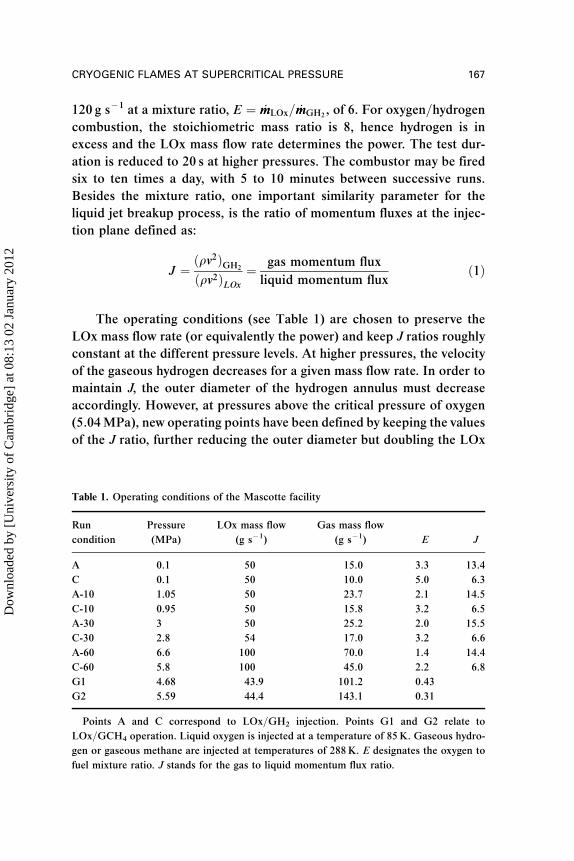
The operating conditions (see Table 1) are chosen to preserve the
LOx mass flow rate (or equivalently the power) and keep J ratios roughly
constant at the different pressure levels. At higher pressures, the velocity
of the gaseous hydrogen decreases for a given mass flow rate. In order to
maintain J, the outer diameter of the hydrogen annulus must decrease
accordingly. However, at pressures above the critical pressure of oxygen
(5.04MPa), new operating points have been defined by keeping the values
of the J ratio, further reducing the outer diameter but doubling the LOx
Table 1. Operating conditions of the Mascotte facility
Run
condition
Pressure
(MPa)
LOx mass flow
(g s�1)
Gas mass flow
(g s�1) E J
A 0.1 50 15.0 3.3 13.4
C 0.1 50 10.0 5.0 6.3
A-10 1.05 50 23.7 2.1 14.5
C-10 0.95 50 15.8 3.2 6.5
A-30 3 50 25.2 2.0 15.5
C-30 2.8 54 17.0 3.2 6.6
A-60 6.6 100 70.0 1.4 14.4
C-60 5.8 100 45.0 2.2 6.8
G1 4.68 43.9 101.2 0.43
G2 5.59 44.4 143.1 0.31
Points A and C correspond to LOx=GH2 injection. Points G1 and G2 relate to
LOx=GCH4 operation. Liquid oxygen is injected at a temperature of 85K. Gaseous hydro-
gen or gaseous methane are injected at temperatures of 288K. E designates the oxygen to
fuel mixture ratio. J stands for the gas to liquid momentum flux ratio.
CRYOGENIC FLAMES AT SUPERCRITICAL PRESSURE 167
Dow
nloa
ded
by [
Uni
vers
ity o
f C
ambr
idge
] at
08:
13 0
2 Ja
nuar
y 20
12
mass flow rate. Trying to reach a pressure of 6.5MPa in the combustor
with a mass flow rate of 50 g s�1 of LOx is technically difficult because
this would require a small nozzle throat that would have been difficult to
cool properly.
More recently, the Mascotte rig was adapted to study LOx=CH4
combustion (version V04). The most notable changes with respect to
the previous versions concern the fuel feed line, which was modified to
allow injection of either hydrogen or methane. The heat exchanger,
placed on the feed system, is powerful enough to liquify the methane
stream at a maximum mass flow rate _mmCH4¼ 250 g s�1. This allows inves-
tigations of combustion conditions in which liquid methane is injected
together with liquid oxygen. The flow rate of oxygen ranges from
_mmLOx ¼ 20 to100 g s�1. The combustion chamber is capable of withstand-
ing pressures up to 10MPa.
Operating conditions are presented in Table 1 for selected experi-
ments at high pressure. In tests G1 and G2, methane is injected as a
gas while the oxygen jet is subcritical (G1) or transcritical (G2). The
mass flow rate of oxygen remains nearly constant at a value
_mmLOx ¼ 45 g s�1. Consequently, the heat release is around 0.55MW for
these two injection conditions if all the oxygen is consumed. The mixture
ratio E ¼ _mmLOx= _mmCH4is between 0.31 and 0.43, well below the mass
stoichiometric value s ¼ 4 characterizing the oxygen=methane reaction.
STRUCTURE OF HIGH-PRESSURE CRYOGENIC FLAMES
Observations of cryogenic combustion at low operating pressures (less
than 1MPa) have provided a wealth of information on the flame struc-
ture in the injector vicinity and in the farfield. It has been possible to
examine effects of injection parameters and propose reasons for the
observed changes in flame spreading. This has guided further experi-
ments and numerical modelling efforts. Control parameters have been
identified on this basis and physical descriptions of the flame structure
have been proposed. This section discusses selected high pressure data
and defines a physical description of the flame structure in the transcri-
tical regime. The word transcritical is used here to designate the state of
a fluid injected at a temperature which is lower than the critical value and
at a pressure which exceeds the critical pressure.
Among the many parameters affecting the flame, it has become
standard to consider the Reynolds numbers of each stream, the Weber
168 S. CANDEL ET AL.
Dow
nloa
ded
by [
Uni
vers
ity o
f C
ambr
idge
] at
08:
13 0
2 Ja
nuar
y 20
12

number of the liquid flow (when the pressure is below critical), the velo-
city ratio V ¼ vH2=vLOx, the injector diameter ratio dH2
=dLOx, the
momentum flux ratio J defined by equation (1), the mixture ratio
E ¼ _mmLO2= _mmH2
and the operating pressure p or the ratio of the pressure
to the critical pressure pc ¼ p=pcrit. A limited number of variables can be
altered on a model scale test facility, such as injector geometry, exhaust
nozzle throat diameter and mass flowrates. Consequently it is not poss-
ible to vary each parameter separately. Instead, it is necessary to study
only parameters which are judged to be the most influential.
From previous engineering experience (see Gill, 1978) and from cold
flow experiments and theoretical considerations, Hopfinger and
Lasheras (1994), Rehab et al. (1997), Villermaux (1998), it was suggested
that the momentum flux ratio, J, was the most influential parameter in
determining the rupture of the central fluid in a coaxial jet, at least under
subcritical conditions where break-up and atomization determine the
liquid droplet sizes. This dimensionless group has served as the main
scaling parameter in the experimental investigations carried out in the
Mascotte test facility. Low-pressure-range experiments carried out with
LOx=GH2 propellants have confirmed that J controls the flame spread
as shown by Herding et al. (1995, 1998) and Snyder et al. (1997). Initial
hot fire tests were carried out in the low-pressure range up to 1MPa
ðpO2¼ p=pcðO2Þ ¼ 0:2Þ. In this range, the oxygen stream behaves like a
liquid jet, which is broken down into ligaments. These are subsequently
atomized by aerodynamic shear stresses induced by the high speed
hydrogen flow. When the chamber pressure is increased beyond
5.04MPa (when pO2> 1), the oxygen jet passes from a subcritical to a
supercritical state and its general structure is modified. Breakup and
atomization prevailing at low pressure are replaced by a turbulent mixing
process which determines the rate of transfer between dense oxygen at a
temperature lower than the critical temperature and light oxygen at a
temperature exceeding the critical value.
Other experiments have focused on the effect of inlet hydrogen tem-
perature. This parameter affects the stabilization of the flame and the
nearfield flow configuration. It was found that under cold-flow con-
ditions some of the water vapor produced by the chemical reaction could
condense to form an annular cloud surrounding the oxygen stream. At
low injection temperatures the cloud was sufficiently dense to diffuse
most of the light emitted by the flame, making visualization difficult
(Juniper, 2001).
CRYOGENIC FLAMES AT SUPERCRITICAL PRESSURE 169
Dow
nloa
ded
by [
Uni
vers
ity o
f C
ambr
idge
] at
08:
13 0
2 Ja
nuar
y 20
12

The operating conditions of hot fire tests are summarized in Table 2.
Values of the momentum flux ratio J have been selected to change the
quality of atomization (inadequate at low values of J, suitable at high
values of this parameter). The value of J is the hardest to keep constant
between tests because it depends on the ratio of the square of the velo-
cities. The desired pressure is also difficult to achieve every time and
there is some dispersion in the values of these parameters.
A large set of optical diagnostics has been used during the various
test series including OH� emission detection, backlighting, spectroscopy,
planar laser light scattering and planar laser induced fluorescence of OH
radicals (see Table 3, Brummund et al. (1995) for a review of optical
diagnostics for cryogenic flames and Candel et al. (1998) for a synthesis
of experiments in the low pressure range). The first three techniques
were exploited in the high pressure range since fluorescence was thought
to be inapplicable due to excessive quenching. However, recent experi-
ments reported by Singla et al. (2005b) indicate that it is possible to
obtain good quality fluorescence data at pressures as high as 6.3MPa.
Structure of Transcritical LOx/GH2 Flames
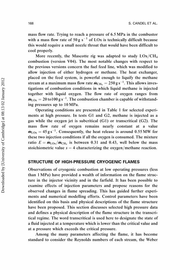
A selection of backlighting images is presented in Figure 3 (top). These
show the dense oxygen jet and the regions containing steep refractive
index gradients in the gas. The intensity of light defines the edge of the
oxygen jet, which is taken to be the position where the intensity gradient
changes most rapidly. Using this method, the oxygen jet position was
found for all images in a sequence. These were then averaged to give a
residence time along the line of sight. This yields a qualitative indication
of the rate of expansion of the dense jet of oxygen.
Table 2. Operating points of the cryogenic test facility (LOx=GH2 combustion)
Previous work (VO1=VO2) New results (VO3)
p (bar) 1, 5, 10 10, 70
Point C: J ¼ 6.3! 6.5 Point C: J ¼ 3.0! 8.0
J Point D0: J ¼ 9.8! 10.2
Point A: J ¼ 13.4! 14.5 Point A: J ¼ 9.0! 13.0
Recess (dLOx) 0, 1 0, 1, 1.5
TH2(K) 298K 298K! 100K
170 S. CANDEL ET AL.
Dow
nloa
ded
by [
Uni
vers
ity o
f C
ambr
idge
] at
08:
13 0
2 Ja
nuar
y 20
12

Table
3.Experim
entalinvestigationsofcryogen
iccombustion
Laser-induced
fluorescen
ceOH,O
2
Emissionim
aging,
Emissiontomography
Backlighting,
Lightscattering
Combined
imaging
Flamestructure
Snyd
eret
al.(1997)
Candel
etal.(1998)
Cessouet
al.(1998)
Herdinget
al.(1995)
Herdinget
al.(1998)
MayerandTamura
(1996)
Herdinget
al.(1995)
MayerandTamura
(1996)
Snyd
eret
al.(1997)
Juniper
etal.(2000)
Injectionparam.
Snyd
eret
al.(1997)
Snyd
eret
al.(1997)
Mayeret
al.(1996)
Snyd
eret
al.(1997)
Effectofpressure
Singla
etal.(2005b)
Juniper
etal.(2000)
Juniper
etal.(2001b)
Singla
etal.(2005a)
Juniper
etal.(2000)
Juniper
etal.(2001b)
Mayeret
al.(1998)
Juniper
etal.(2001b)
Singla
etal.(2005a)
Flamestab.
Herdinget
al.(1996)
Mayeret
al.(1998)
Mayeret
al.(1998)
Juniper
etal.(2000)
Singla
etal.(2005a)
Effectofrecess
Ken
dricket
al.(1998)
Ken
dricket
al.(1999)
Tripathiet
al.(1999)
Juniper
etal.(2001a)
Juniper
etal.(2005)
Juniper
etal.(2001a)
Thetable
only
includes
imagingstudies.
171
Dow
nloa
ded
by [
Uni
vers
ity o
f C
ambr
idge
] at
08:
13 0
2 Ja
nuar
y 20
12
A selection of instantaneous OH� emission images is shown in Fig-
ure 3 (bottom). These images, taken just after the backlighting images,
correspond to exactly the same operating point and camera position.
These images can also be averaged and processed with the Abel inver-
sion (see Herding et al. (1998) for a presentation of this method and pro-
cessing of low pressure flames and Juniper et al. (2000) for a discussion
of its application in the high pressure range). The transformation yields
the position of the average flame. These data may then be merged with
the average oxygen jet position deduced from backlighting to form com-
posite images as in Figure 4. (Note that in the top picture the average jet
position near the injector was not available due to a partial icing of the
visualization window close to the injection plane and corresponding
screening of the light beam).
As in the low-pressure range, the flame begins at the injector, it
spreads in the vicinity of the oxygen jet and does not penetrate into
Figure 3. A sample of instantaneous backlighting images (top) and instantaneous OH�
images (bottom) for the broad field. The operating points and camera position are identical
in both sets of images: Point C, p ¼ 7MPa (See Color Plate 4 at the end of this issue).
172 S. CANDEL ET AL.
Dow
nloa
ded
by [
Uni
vers
ity o
f C
ambr
idge
] at
08:
13 0
2 Ja
nuar
y 20
12

the central core occupied by the dense stream of oxygen. In the high
pressure range, the flame expansion angle is much smaller than
that found in the low pressure experiments. It is also found that the
Figure 4. Combined emission and backlighting images. The colour scale corresponds to a
slice of OH� emission and the grayscale to the average jet position. Top: Point A, zero
recess. Middle: Point C, zero recess. Bottom: Point C, recess of 1� dLOx (See Color Plate
5 at the end of this issue).
CRYOGENIC FLAMES AT SUPERCRITICAL PRESSURE 173
Dow
nloa
ded
by [
Uni
vers
ity o
f C
ambr
idge
] at
08:
13 0
2 Ja
nuar
y 20
12
momentum flux ratio has less influence in this range. A detailed examin-
ation of the data gathered is carried out in Juniper et al. (2001b). A sim-
plified model providing an interpretation of the spreading rates observed
experimentally is given by Juniper et al. (2002). It is found that the low
pressure flames are controlled by vaporization of droplets produced by
the liquid jet breakup and subsequent atomization. The momentum flux
ratio J determines the breakup process. In the high-pressure range,
beyond the critical pressure of oxygen ( p > 5.05MPa), the flame spread-
ing rate is controlled by turbulent mixing of the dense stream of oxygen
with the lighter surroundings. The controlling mechanism is mass trans-
fer from the dense jet to the lighter surrounding gas and this is mainly
governed by the amount of interfacial surface between the dense and
light fluids and by the local strain rates (see Jay et al., 2005, for a model
accounting for these effects). Under these circumstances, the momen-
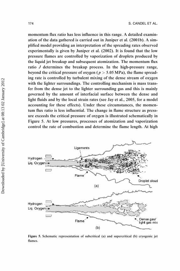
tum flux ratio is less influential. The change in flame structure as press-
ure exceeds the critical pressure of oxygen is illustrated schematically in
Figure 5. At low pressures, processes of atomization and vaporization
control the rate of combustion and determine the flame length. At high
Figure 5. Schematic representation of subcritical (a) and supercritical (b) cryogenic jet
flames.
174 S. CANDEL ET AL.
Dow
nloa
ded
by [
Uni
vers
ity o
f C
ambr
idge
] at
08:
13 0
2 Ja
nuar
y 20
12
pressures, mass transfer between the dense transcritical fluid and its
surroundings is the rate controlling process.
Effect of Recess on Transcritical LOx/GH2 Flames
It is known from many hot fire tests on complete engines that combus-
tion efficiency is improved when the central injector is recessed inside
the outer tube, as shown in Figure 1. Experiments carried out in the
low pressure range ð p < pcðO2ÞÞ indicate that recessing the LOx tube
has a significant effect on flame spread (Kendrick et al., 1998, 1999).
To explain these observations a one dimensional model of the internal
flow is established in which the flame stabilized on the liquid oxygen
injector lip, spreads inside the injector when the central tube is recessed.
The flux of products formed by combustion inside the channel occupies
part of the available area and, because of volumetric expansion, acceler-
ates the outer gas flow. The momentum flux of the outer stream is aug-
mented and this accelerates the liquid core breakup and improves its
atomization thus augmenting the flame expansion rate. It has also been
found in cold-flow experiments at low pressures, Strakey et al. (2002),
that post biasing may be used to shift the liquid flux distribution away
from the chamber wall.
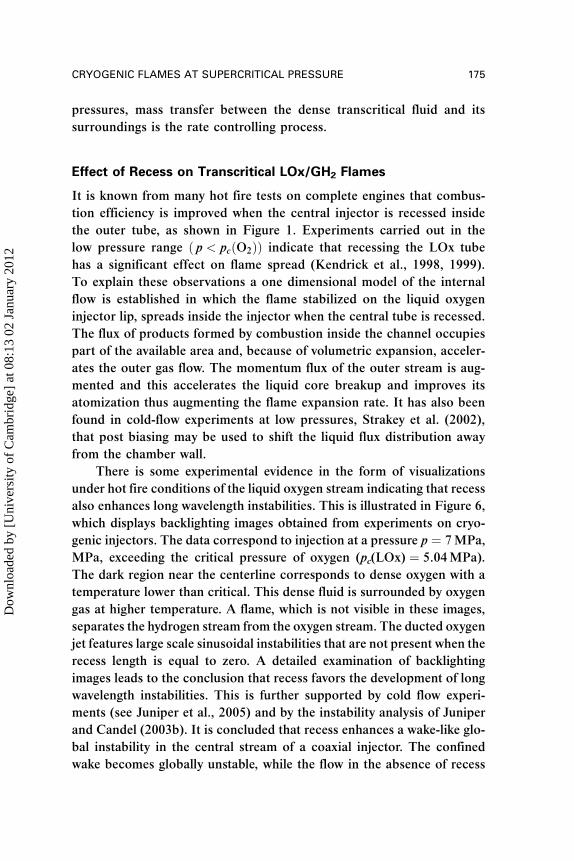
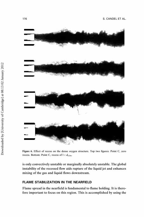
There is some experimental evidence in the form of visualizations
under hot fire conditions of the liquid oxygen stream indicating that recess
also enhances long wavelength instabilities. This is illustrated in Figure 6,
which displays backlighting images obtained from experiments on cryo-
genic injectors. The data correspond to injection at a pressure p ¼ 7MPa,
MPa, exceeding the critical pressure of oxygen (pc(LOx) ¼ 5.04MPa).
The dark region near the centerline corresponds to dense oxygen with a
temperature lower than critical. This dense fluid is surrounded by oxygen
gas at higher temperature. A flame, which is not visible in these images,
separates the hydrogen stream from the oxygen stream. The ducted oxygen
jet features large scale sinusoidal instabilities that are not present when the
recess length is equal to zero. A detailed examination of backlighting
images leads to the conclusion that recess favors the development of long
wavelength instabilities. This is further supported by cold flow experi-
ments (see Juniper et al., 2005) and by the instability analysis of Juniper
and Candel (2003b). It is concluded that recess enhances a wake-like glo-
bal instability in the central stream of a coaxial injector. The confined
wake becomes globally unstable, while the flow in the absence of recess
CRYOGENIC FLAMES AT SUPERCRITICAL PRESSURE 175
Dow
nloa
ded
by [
Uni
vers
ity o
f C
ambr
idge
] at
08:
13 0
2 Ja
nuar
y 20
12
is only convectively unstable or marginally absolutely unstable. The global
instability of the recessed flow aids rupture of the liquid jet and enhances
mixing of the gas and liquid flows downstream.
FLAME STABILIZATION IN THE NEARFIELD
Flame spread in the nearfield is fundamental to flame holding. It is there-
fore important to focus on this region. This is accomplished by using the
Figure 6. Effect of recess on the dense oxygen structure. Top two figures: Point C, zero
recess. Bottom: Point C, recess of l� dLOx.
176 S. CANDEL ET AL.
Dow
nloa
ded
by [
Uni
vers
ity o
f C
ambr
idge
] at
08:
13 0
2 Ja
nuar
y 20
12

same optical techniques combining emission and backlighting imaging
(Juniper et al., 2001a). The backlighting setup is influenced by Schlieren
effects because beam deviations are strong enough to deflect light out of
the cone which is captured by the camera. Typical nearfield backlighting
images obtained in the low and high pressure ranges are displayed in
Figure 7.
The liquid oxygen jet appears as a dark black region in the two cases.
The frontier of this jet is quite clear when the pressure is low and a thin
interface separates the liquid from the gas. In the high-pressure situation,
this frontier is fuzzy but still quite visible. The annular hydrogen stream is
also distinguishable in both cases. When these images are averaged, the
darkness of a pixel corresponds to the average time that a strong gradient
has existed at that pixel’s position. The strongest deviation occurs where
gradients are perpendicular to the ray direction, which is in a slice
through the jet’s axis. Thus, to a first approximation, the images can
be considered to be a slice of this plane and can be compared with the
Abel-inverted emission images.
Instantaneous emission images obtained in the nearfield can be aver-
aged and processed with the Abel inversion. They can then be superim-
posed on the average backlighting images, as shown in Figure 8. The
flame edge is located in the near vicinity of the LOx injector and the
flame then closely follows the dense oxygen boundary. Heat released
by chemical conversion taking place near the dense oxygen stream
induces a gradient of temperature and a steep change in oxygen density.
The experimental data indicate that the flame is attached to the oxygen
injector lip but that the anchor point is at a finite distance from the step.
This is observed over the complete range of pressures, inlet velocities
and hydrogen temperatures studied and illustrated in Figure 9, which
shows the flame structure near the injection plane and a closeup of the
vicinity of the LOx post lip. The flame edge is located just behind the
lip at a small distance from this boundary. It is shown in a recent article
by Juniper and Candel (2003c) and briefly summarized in the last section
that the injector lip serves to stabilize the flame. Theoretical considera-
tions and simulations of this region indicate that the most influential
parameter is a nondimensional step height W, which measures the size
of the lip with respect to the flame thickness W ¼ hs=df . When this para-
meter is large, the flame tucks behind the lip and is affected little by the
Damkohler number. When this is small, the flame is thicker than the lip
and it is exposed to the high speed hydrogen stream and becomes very
CRYOGENIC FLAMES AT SUPERCRITICAL PRESSURE 177
Dow
nloa
ded
by [
Uni
vers
ity o
f C
ambr
idge
] at
08:
13 0
2 Ja
nuar
y 20
12

Figure 7. Instantaneous backlighting images obtained in the nearfield. Top, p ¼ 1MPa,
zero recess. Bottom, point C, p ¼ 7MPa, zero recess.
178 S. CANDEL ET AL.
Dow
nloa
ded
by [
Uni
vers
ity o
f C
ambr
idge
] at
08:
13 0
2 Ja
nuar
y 20
12
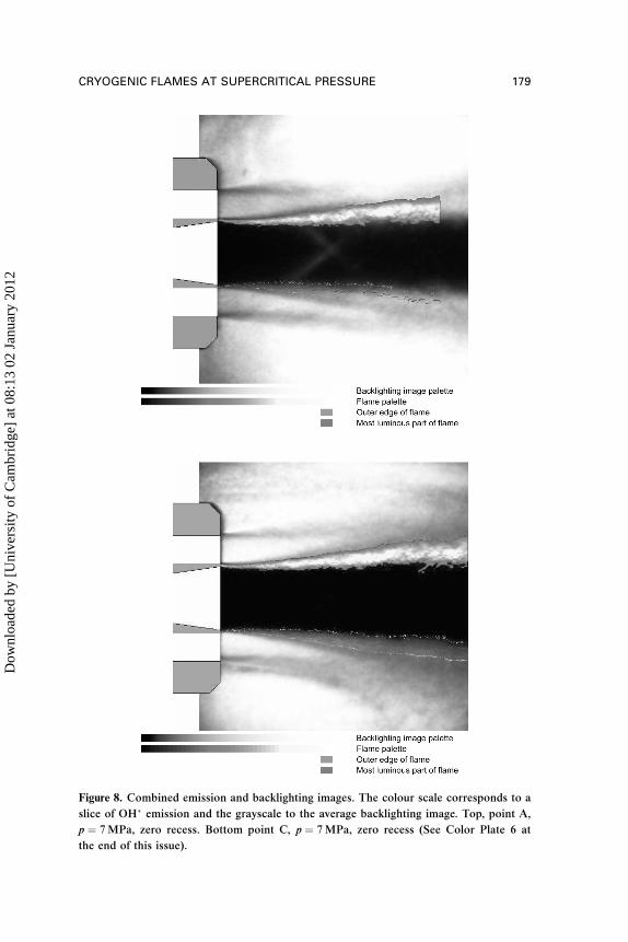
Figure 8. Combined emission and backlighting images. The colour scale corresponds to a
slice of OH� emission and the grayscale to the average backlighting image. Top, point A,
p ¼ 7MPa, zero recess. Bottom point C, p ¼ 7MPa, zero recess (See Color Plate 6 at
the end of this issue).
CRYOGENIC FLAMES AT SUPERCRITICAL PRESSURE 179
Dow
nloa
ded
by [
Uni
vers
ity o
f C
ambr
idge
] at
08:
13 0
2 Ja
nuar
y 20
12

sensitive to the Damkohler number. Figure 9 corresponds to a case
where W>1 and one expects that the flame will be well stabilized. More
recent instantaneous images obtained by planar laser induced fluores-
cence of OH (Singla et al., 2005b) indicate that the anchor point is
not fixed in space but moves around behind the oxygen lip. The spatial
distribution of OH in the flame has a thickness which is comparable to
the lip size. The flame is probably stabilized at other points around the
circumference. It is also possible to consider that the lip size should
be augmented by the thickness of the boundary layers established in
the gas and liquid streams and that the stability criterion should be based
on this augmented size: W ¼ h�s=df where h�s ¼ hs þ dLOx þ dGH2
:
INJECTION OF SUB- AND TRANSCRITICAL
O2/SUPERCRITICAL CH4
Research on cryogenic combustion has mainly concerned liquid oxygen
and gaseous hydrogen at various chamber pressures (0.1 to 7MPa).
There is, however, interest in the development of reusable liquid rocket
engines operating with methane and oxygen as propellants. It is worth
discussing fundamental information on the combustion process involving
Figure 9. Combined emission and backlighting images. The colour scale corresponds to a
slice of OH� emission and the grayscale to the average backlighting image. Adapted from
Juniper et al. (2000) (See Color Plate 7 at the end of this issue).
180 S. CANDEL ET AL.
Dow
nloa
ded
by [
Uni
vers
ity o
f C
ambr
idge
] at
08:
13 0
2 Ja
nuar
y 20
12

this couple of propellants. One may envisage a situation in which both
propellants are injected in a transcritical state and another set of con-
ditions where oxygen is injected in a subcritical or transcritical state
while methane is injected as a gas in a supercritical state. These various
possibilities, explored by Singla et al. (2005a), indicate that the flame
formed in the first situation differs significantly from the more standard
cases involving one gaseous stream. This case will not be treated here
and we only consider results corresponding to supercritical injection of
methane and subcritical (G1) or transcritical (G2) injection of oxygen
(Figure 10a, 10b). Injection conditions are gathered in Table 1. Figures
10a and 10b show Abel transforms of time average OH� emission
images. Nearfield images obtained from CH� emission are also given
in Singla et al. (2005a). The flame position with respect to the LOx jet
Figure 10. Liquid oxygen=gaseous methane combustion. Combined Abel transformed
emission and backlighting images. The transformation is applied to average emission
images obtained by summing 200 instantaneous images with exposure time 30ms. The colorscale corresponds to a slice of OH� emission and the light to dark blue scale to the average
jet position, (a) Point of operation G1, (b) Point of operation G2. From Singla et al. (2005a)
(See Color Plate 8 at the end of this issue).
CRYOGENIC FLAMES AT SUPERCRITICAL PRESSURE 181
Dow
nloa
ded
by [
Uni
vers
ity o
f C
ambr
idge
] at
08:
13 0
2 Ja
nuar
y 20
12
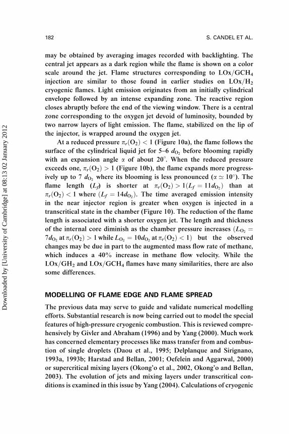
may be obtained by averaging images recorded with backlighting. The
central jet appears as a dark region while the flame is shown on a color
scale around the jet. Flame structures corresponding to LOx=GCH4
injection are similar to those found in earlier studies on LOx=H2
cryogenic flames. Light emission originates from an initially cylindrical
envelope followed by an intense expanding zone. The reactive region
closes abruptly before the end of the viewing window. There is a central
zone corresponding to the oxygen jet devoid of luminosity, bounded by
two narrow layers of light emission. The flame, stabilized on the lip of
the injector, is wrapped around the oxygen jet.
At a reduced pressure prðO2Þ < 1 (Figure 10a), the flame follows the
surface of the cylindrical liquid jet for 5–6 dO2before blooming rapidly
with an expansion angle a of about 20�. When the reduced pressure
exceeds one, prðO2Þ > 1 (Figure 10b), the flame expands more progress-
ively up to 7 dO2where its blooming is less pronounced (a ’ 10�). The
flame length (Lf) is shorter at prðO2Þ > 1ðLf ¼ 11dO2Þ than at
prðO2Þ < 1 where ðLf ¼ 14dO2Þ. The time averaged emission intensity
in the near injector region is greater when oxygen is injected in a
transcritical state in the chamber (Figure 10). The reduction of the flame
length is associated with a shorter oxygen jet. The length and thickness
of the internal core diminish as the chamber pressure increases ðLO2¼
7dO2at prðO2Þ > 1whileLO2
¼ 10dO2at prðO2Þ < 1Þ but the observed
changes may be due in part to the augmented mass flow rate of methane,
which induces a 40% increase in methane flow velocity. While the
LOx=GH2 and LOx=GCH4 flames have many similarities, there are also
some differences.
MODELLING OF FLAME EDGE AND FLAME SPREAD
The previous data may serve to guide and validate numerical modelling
efforts. Substantial research is now being carried out to model the special
features of high-pressure cryogenic combustion. This is reviewed compre-
hensively by Givler and Abraham (1996) and by Yang (2000). Much work
has concerned elementary processes like mass transfer from and combus-
tion of single droplets (Daou et al., 1995; Delplanque and Sirignano,
1993a, 1993b; Harstad and Bellan, 2001; Oefelein and Aggarwal, 2000)
or supercritical mixing layers (Okong’o et al., 2002, Okong’o and Bellan,
2003). The evolution of jets and mixing layers under transcritical con-
ditions is examined in this issue by Yang (2004). Calculations of cryogenic
182 S. CANDEL ET AL.
Dow
nloa
ded
by [
Uni
vers
ity o
f C
ambr
idge
] at
08:
13 0
2 Ja
nuar
y 20
12

flames have also been carried out in the classical RANS framework or
with modern LES tools as in Oefelein and Yang (1998).
The stabilization mechanism of cryogenic flames is another topic of
scientific and technical interest. It is known from experimental studies
such as those described in the previous sections that the flame is stabi-
lized in the wake of the oxygen injector lip and that it develops in the
near vicinity of the oxygen flow. This is also observed in the simulations
of Oefelein and Yang (1998). Under normal operating conditions, the
flame is stable, the flame edge is close to the lip and the reaction front
develops near the oxygen stream boundary. At some distance from the
injection plane it becomes a highly turbulent brush. It is also known that
below a critical hydrogen feed temperature, oscillations may develop at
frequencies corresponding to the chamber’s acoustic modes. Tempera-
ture seems to control the onset of this process, which suggests that the
flame could lift off the oxygen injector making it more sensitive to acous-
tic coupling. With appropriate feedback this would lead to the observed
oscillations; however, direct optical observations of this phenomenon are
not available.
The mechanism that governs stabilization and the control para-
meters of this process are not well documented, even though they are
essential in engineering analysis. Current practice relies on accumulated
experience but a fundamental approach is needed (see Juniper and
Candel, 2003c). It is first useful to imagine the different types of flame
geometries as in Figure 11 and then use detailed calculations to identify
configurations corresponding to stable flames and conditions leading to
flame liftoff.
In these various schemes the flame base plays a central role. The
analysis can be considered in two parts by distinguishing:
. A hot slow-moving zone just behind the oxygen injector lip in which
the flow is laminar;
. A thin-spreading diffusion flame which becomes turbulent within a few
millimetres.
Three mechanisms of flame blowout are possible.
1. A pilot flame remains shielded in the recirculation zone but the turbu-
lent flame is extinguished just downstream in regions of excessive
strain rate,
CRYOGENIC FLAMES AT SUPERCRITICAL PRESSURE 183
Dow
nloa
ded
by [
Uni
vers
ity o
f C
ambr
idge
] at
08:
13 0
2 Ja
nuar
y 20
12
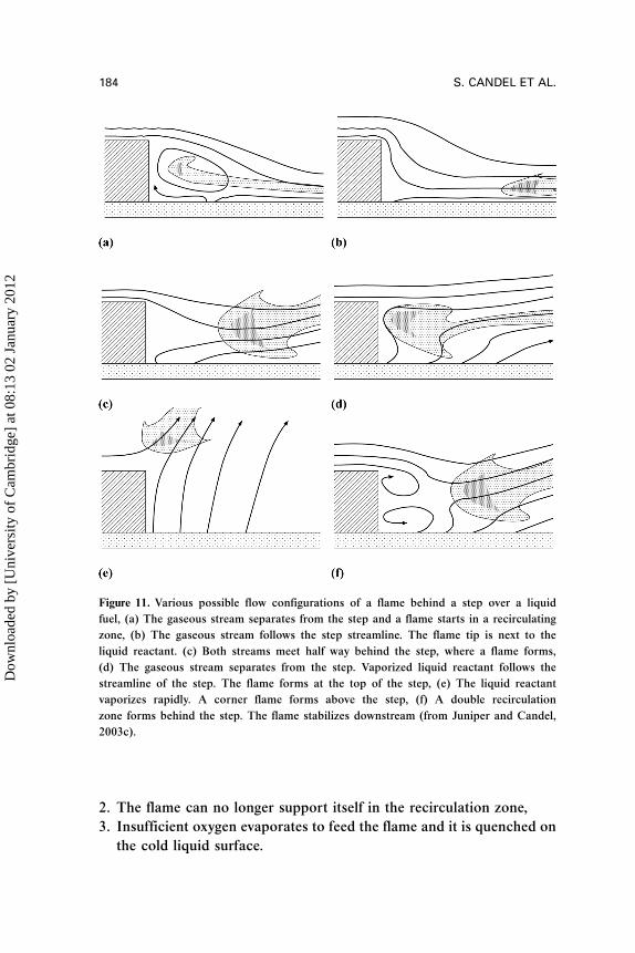
2. The flame can no longer support itself in the recirculation zone,
3. Insufficient oxygen evaporates to feed the flame and it is quenched on
the cold liquid surface.
Figure 11. Various possible flow configurations of a flame behind a step over a liquid
fuel, (a) The gaseous stream separates from the step and a flame starts in a recirculating
zone, (b) The gaseous stream follows the step streamline. The flame tip is next to the
liquid reactant. (c) Both streams meet half way behind the step, where a flame forms,
(d) The gaseous stream separates from the step. Vaporized liquid reactant follows the
streamline of the step. The flame forms at the top of the step, (e) The liquid reactant
vaporizes rapidly. A corner flame forms above the step, (f) A double recirculation
zone forms behind the step. The flame stabilizes downstream (from Juniper and Candel,
2003c).
184 S. CANDEL ET AL.
Dow
nloa
ded
by [
Uni
vers
ity o
f C
ambr
idge
] at
08:
13 0
2 Ja
nuar
y 20
12

The first blowout mechanism is explored in Juniper et al. (2003) by
considering a counterflow hydrogen flame above condensed oxygen. It is
shown that, at pressures of 1 bar and above, extinction by strain is
impossible, even if the flame is pinched against the liquid oxygen surface.
This reduces the study to the region just behind the lip of the oxygen
injector.
The second and third extinction mechanisms are explored in Juniper
and Candel (2003a) and Juniper and Candel (2003c) with particular ref-
erence to three nondimensional parameters, which are introduced in
carefully planned stages. The first parameter is a Damkohler number
affecting flame standoff distance in a cross-flow flame. This configur-
ation is simple enough to permit theoretical analysis (see Mahalingam
and Weidman, 2002). Another situation of interest is that of a flame
above a liquid fuel. This introduces a new physical feature, vaporization,
which requires another nondimensional parameter: the ratio of heat
release due to chemical reaction to the liquid’s latent heat of vaporiza-
tion. The final parameter, the ratio of the LOx tube thickness to the flame
Figure 12. Hydrogen flame above condensed oxygen tucked behind a step of height 0.4mm.
The volumetric heat release is plotted on a color scale (max ¼ 1.2� 1011 Jm� 3 s� 1). Solid
contours correspond to streamlines. UH2¼ 190m s�1 TH2
¼ 350K, TLOx ¼ 90K,
p ¼ 0.1MPa (from Juniper and Candel, 2003c) (See Color Plate 9 at the end of this issue).
CRYOGENIC FLAMES AT SUPERCRITICAL PRESSURE 185
Dow
nloa
ded
by [
Uni
vers
ity o
f C
ambr
idge
] at
08:
13 0
2 Ja
nuar
y 20
12
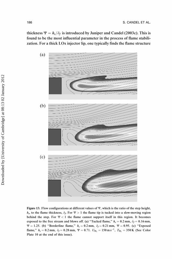
thicknessW ¼ hs=df is introduced by Juniper and Candel (2003c). This is
found to be the most influential parameter in the process of flame stabili-
zation. For a thick LOx injector lip, one typically finds the flame structure
Figure 13. Flow configurations at different values of W, which is the ratio of the step height,
hs, to the flame thickness, df. For W > 1 the flame tip is tucked into a slow-moving region
behind the step. For W < 1 the flame cannot support itself in this region. It becomes
exposed to the free stream and blows off. (a) ‘‘Tucked flame,’’ hs ¼ 0.2mm, df ¼ 0.16mm,
W ¼ 1.25. (b) ‘‘Borderline flame,’’ hs ¼ 0.2mm, df ¼ 0.21mm, W ¼ 0.95. (c) ‘‘Exposed
flame,’’ hs ¼ 0.2mm, df ¼ 0.28mm, W ¼ 0.71. UH2¼ 150m s�1, TH2
¼ 350K (See Color
Plate 10 at the end of this issue).
186 S. CANDEL ET AL.
Dow
nloa
ded
by [
Uni
vers
ity o
f C
ambr
idge
] at
08:
13 0
2 Ja
nuar
y 20
12

shown in Figure 12. The hydrogen stream separates from the edge of the
step and the flame can tuck in the slow moving stream behind the step.
The geometry is that of Figure 11(d). The configuration is similar to that
of Oefelein and Yang (1998) and Deshpande et al. (1997). Results for a
thinner lip hs ¼ 0.20mm are shown in Figure 13. In all cases at this high
value of UH2, the hydrogen stream separates from the edge of the step.
There are two types of results, depending on W. When the step exceeds
the flame thickness, Figure 13(a), the flame can tuck into the slow-mov-
ing region behind the step. However, when the step size is smaller than
the flame thickness, Figure 13(c), the flame is forced out of this zone.
It then finds itself exposed to the main stream and is swept away. The
latter type of solution is only stable for very low hydrogen velocities.
The borderline case is obtained when the step height is equal to the flame
thickness as shown in Figure 13(b).
The conclusions presented here are for H2=O2 flames at 1 bar but the
same approach could be used at higher pressures to analyze flamehold-
ing. Because the analysis is carried out in terms of dimensionless groups,
it should also be valid for other reactant combinations such as O2=CH4
and should provide a useful guideline for designing injectors.
CONCLUSIONS AND PERSPECTIVES
Research described in this article concerns cryogenic combustion in the
high pressure range. Experiments carried out on the Mascotte facility
cover a wide range of pressure (0.1 to 7MPa). Some experiments were
also carried out with LOx=methane injection. The gas to liquid momen-
tum flux ratio ranges from 4 to 15 in the LOx=hydrogen flames and it is
higher in the LOx=methane experiments. Emission and backlighting
images obtained with two synchronized ICCD cameras provide a view
of the LOx jet and the flame. The mean flame structure is extracted by
taking the Abel transform of average emission images. This reveals the
main features of the flame structure.
In the low-pressure range, below the critical pressure of oxygen
(5.04MPa) the flame burns in an external group combustion mode
and takes the shape of a shell surrounding the LOx jet and LOx droplet
cloud. This is well documented in previous studies. Detailed examination
of the experimental results combined with simplified modelling indicates
a change in behavior when the pressure exceeds the critical pressure of
oxygen. Experimental and theoretical results indicate that the rate of
CRYOGENIC FLAMES AT SUPERCRITICAL PRESSURE 187
Dow
nloa
ded
by [
Uni
vers
ity o
f C
ambr
idge
] at
08:
13 0
2 Ja
nuar
y 20
12
combustion is vaporization-limited when the pressure is below the criti-
cal pressure and is mixing-limited when the pressure is above the critical
pressure. This suggests that, rather than improving atomization, one
should attempt to increase mixing inside combustion chambers designed
to operate above the critical pressure of the liquid reactant.
Experimental results also show that the flame remains attached to
the lip of the oxygen injector over the complete range of pressure, inlet
velocity and hydrogen temperatures studied. The stabilization mech-
anism has been elucidated by combining experimental information and
detailed calculations of this small but important region of the flow.
Research that has mainly concerned stable cryogenic flames formed by
liquid oxygen and gaseous hydrogen now focuses on LOx=methane
flames and on combustion dynamics and high frequency instabilities, a
central problem in rocket propulsion. A program has been established
by a French-German consortium formed by CNES, DLR, Snecma,
EADS Astrium, Onera, and CNRS laboratories and a combination of
experimental and computational investigations is underway.
REFERENCES
Barrere, M., Jaumotte, A., Fraeijs de Veubeke, B., and Vandenkerckhove, J.
(1960) Rocket Propulsion, Elsevier, Amsterdam.
Brummund, U., Cessou, A., Oschwald, M.,Vogel, A., Grisch, F., Bouchardy, P.,
Pealat, M., Vingert, L., Habiballah, M., Snyder, R., Herding, G., Scouflaire, P.,
Rolon, C., and Candel, S. (1995) Laser diagnostics for cryogenic propel-
lant combustion studies. 2nd International Symposium on Liquid Rocket
Propulsion, Chatillon, France, pp. 19.1–19.21.
Burick, R.J. (1972) Atomization and mixing characteristics of gas=liquid coaxial
injector elements. J. Spacecraft, 9, 326–331.
Burick, R.J. (1973) Optimum design of space storable gas=liquid coaxial injec-
tors. J. Spacecraft, 10, 663–670.
Candel, S., Herding, G., Snyder, R., Scouflaire, P., Rolon, C., Vingert, L.,
Habiballah, M., Grisch, F., Pealat, M., Bouchardy, P., Stepowsky, D.,
Cessou, A., and Colin, P. (1998) Experimental investigation of shear coaxial
cryogenic jet flames. J. Propul. Power, 14, 826–834.
Candel, S., Juniper, M., Scouflaire, P., Rolon, C., Clauss, W., Klimenko, D.N.,
Oschwald, M., Grisch, F., Bouchardy, P., and Vingert, L. (2003) Investiga-
tions of subcritical and transcritical cryogenic combustion using laser ima-
ging and laser techniques. 5th International Space Propulsion Conference,
Chattanooga, Tennessee, CD Proceedings.
188 S. CANDEL ET AL.
Dow
nloa
ded
by [
Uni
vers
ity o
f C
ambr
idge
] at
08:
13 0
2 Ja
nuar
y 20
12

Cessou, A., Colin, P., and Stepowski, D. (1998) Statistical Investigation of the
Turbulent Flame Geometrical Structures in a Liquid Oxygen=Gaseous
Hydrogen Shear Coaxial Jet. Proc. Combust. Instit., 27, 1039–1046.
Daou, J., Haldenwang, P., and Nicoli, C. (1995) Supercritical burning of liquid
oxygen (LOx) droplet with detailed chemistry. Combust. Sci. Technol., 101,
153–169.
Delplanque, J.P. and Sirignano, W.A. (1993a) Numerical study of the transient
vaporization of an oxygen droplet at sub- and supercritical conditions. Inter.
J. Heat Mass Trans., 36, 303–314.
Delplanque, J.P. and Sirignano, W.A. (1993b) Stability of transcritical LOx drop-
let vaporization in an idealized rocket combustor, AIAA Paper 93-0231.
AIAA, Washington, D.C.
Deshpande, M., Venkateswaran, S., Foust, M., and Merkle, C. (1997) Finite split-
ter plate effects on flame holding in a confined hydrogen-oxygen shear layer,
AIAA Paper 97-0258. AIAA, Washington, D.C.
Gill, G.S. (1978) A qualitative technique for concentric tube element optimiza-
tion, utilizing the factor (dynamic head ratio-1), AIAA Paper 78-76. AIAA,
Washington, D.C.
Givler, S.D. and Abraham, J. (1996) Supercritical droplet vaporization and
combustion studies. Prog. Energy Combust. Sci., 22, 1–28.
Haarje, D.T. and Reardon, F.M. (1972) Liquid propellant rocket combustion
instability, NASA SP 194, NASA, Washington, D.C.
Harstad, K. and Bellan, J. (2001) The d2 variation for isolated LOX drops
and polydisperse clusters in hydrogen at high temperature and pressures.
Combust. Flame, 124, 535–550.
Herding, G., Snyder, R., Rolon, C., and Candel, S. (1998) Investigation of cryo-
genic propellant flames using computerized tomography of OH emission
images. J. Propul. Power, 13, 146–151.
Herding, G., Snyder, R., Scouflaire, P., Rolon, C., and Candel, S. (1995)
Emission and laser induced fluorescence imaging of cryogenic propellant
combustion. Conference on Propulsive Flows in Space Transportation Systems,
Bordeaux, France, pp. 1–14.
Herding, G., Snyder, R., Scouflaire, P., Rolon, C., and Candel, S. (1996) Flame
stabilization in cryogenic propellant combustion. Proc. Combust. Instit., 26,
2041–2047.
Hopfinger, E. and Lasheras, J.C. (1994) Breakup of a water jet in high velocity
co-flowing air. In Yule, A.J. and Dumouchel, C. (Eds.) Proceedings of the
6th International Conference on Liquid Atomization, Begell House, New York,
pp. 110–117.
Jay, S., Lacas, F., and Candel, S. (2005) Combined surface density concepts for
dense spray combustion. Combust. Flame, In Press.
CRYOGENIC FLAMES AT SUPERCRITICAL PRESSURE 189
Dow
nloa
ded
by [
Uni
vers
ity o
f C
ambr
idge
] at
08:
13 0
2 Ja
nuar
y 20
12

Juniper, M. (2001) Structure et stabilisation des flammes cryotechniques,
Doctoral thesis, Ecole Centrale Paris, Chatenay-Malabry.
Juniper, M. and Candel, S. (2003a) The effect of Damkohler number on the
stand-off distance of cross-flow flames. Combust. Theory Model., 7, 563–577.
Juniper, M. and Candel, S. (2003b) The stability of ducted compound flows
and consequences for the geometry of coaxial injectors. J. Fluid Mech.,
482, 257–269.
Juniper, M. and Candel, S. (2003c) Stabilization of an edge diffusion flame
behind a step over a liquid reactant. J. Propul. Power, 19, 332–342.
Juniper, M., Darabiha, N., and Candel, S. (2003) The extinction limits of a
hydrogen counterflow diffusion flame above liquid oxygen. Combust. Flame,
135, 87–96.
Juniper, M., Leroux, B., Lacas, F., and Candel, S. (2005) Experimental determi-
nation of the instability mechanism in recessed coaxial injectors. Experi-
ments in Fluids, Submitted.
Juniper, M., Tripathi, A., Leroux, B., Lacas, F., and Candel, S. (2001a) Stabiliza-
tion of cryogenic flames and effect of recess. In Combustion dans les moteurs
fusees, Cepadues Toulouse, pp. 222–231.
Juniper, M., Tripathi, A., Scouflaire, P., and Candel, S. (2002) Turbulent combus-
tion of sprays under supercritical conditions. In Pollard, A. and Candel, S.
(Eds.) Turbulent Mixing and Combustion, Kluwer, Dordrecht, pp. 439–446.
Juniper,M., Tripathi,A., Scouflaire, P.,Rolon,C., andCandel, S. (2000)Structure of
cryogenic flames at elevated pressures. Proc. Combust. Instit., 28, 1103–1109.
Juniper, M., Tripathi, A., Scouflaire, P., Rolon, C., and Candel, S. (2001b)
The structure of cryogenic flames at subcritical and supercritical pressures.
Combustion dans les moteurs fusees, Cepadues Toulouse, pp. 348–357.
Kendrick, D., Herding, G., Scouflaire, P., Rolon, C., and Candel, S. (1998) Effet
du retrait sur la stabilisation des flammes cryotechniques. Comptes Rendus
de l’ Academie des Sciences, Serie II b, 326, 111–116.
Kendrick, D., Herding, G., Scouflaire, P., Rolon, C., and Candel, S. (1999)
Effects of a recess on cryogenic flame stabilization. Combust. Flame, 118,
327–339.
Liang, P.Y., Fisher, S., and Chang, Y.M. (1985) Comprehensive modeling of a
liquid rocket combustion chamber, AIAA Paper 85-0232.
Mahalingam, S. and Weidman, P. (2002) Activation energy asymptotic analysis
and numerical modelling of a strained laminar corner flame. Combust.
Theory Modelling, 6, 155–172.
Mayer, W. and Tamura, H. (1996) Propellant injection in a liquid rocket
oxygen=gaseous hydrogen rocket engine. J. Propul. Power, 12, 1137–1147.
Mayer, W., Schik, A., Schaeffler, M., and Tamura, H. (2000) Injection and
mixing processes in high pressure liquid oxygen=gaseous hydrogen rocket
combustors. J. Propul. Power, 15, 823–828.
190 S. CANDEL ET AL.
Dow
nloa
ded
by [
Uni
vers
ity o
f C
ambr
idge
] at
08:
13 0
2 Ja
nuar
y 20
12

Mayer, W., Schik, A., Schweitzer, C., and Schaffler, M. (1996) Injection and mix-
ing processes in high pressure LOx=GH2 rocket combustors, AIAA Paper
96-2620.
Mayer, W., Snick, A., Vielle, B., Chauveau, C., Gokalp, I., Talley, D., and
Woodward, R. (1998) Atomization and breakup of cryogenic propellants
under high-pressure subcritical and supercritical conditions. J. Propul.
Power, 14, 835–842.
Mayer, W.O.H., Ivancic, B., Schik, A., and Hornung, U. (2001) Propellant atomi-
zation and ignition phenomena in liquid oxygen=gaseous hydrogen rocket
combustors. J. Propul. Power, 17, 794–799.
Oefelein, J. and Aggarwal, S.K. (2000) Toward a unified high-pressure drop
model for spray simulations. Center for Turbulence Research Summer Pro-
gram, Stanford University, pp. 193–205.
Oefelein, J. and Yang, V. (1998) Modeling high-pressure mixing and combustion
processes in liquid rocket engines. J. Propul. Power, 14, 843–857.
Okong’o, N. and Bellan, J. (2003) Real-gas effects on mean flow and temporal
stability of binary-species mixing layers. AIAA J., 41, 2429–2443.
Okong’o, N., Harstad, K., and Bellan, J. (2002) Direct numerical simulations of
O2=H2 temporal mixing layers under supercritical conditions. AIAA J., 40,
914–926.
Pal, S., Moser, M.D., Ryan, H.M., Foust, M.J., and Santoro, R.J. (1996) Shear
coaxial injector atomization phenomena for combusting and non combust-
ing conditions. Atomization Sprays, 6, 227–244.
Rehab, H., Villermaux, E., and Hopfinger, E. (1997) Flow regimes of large
velocity ratio coaxial jets. J. Fluid Mech., 345, 357–381.
Singla, G., Scouflaire, P., Rolon, C., and Candel, S. (2005a) Transcritical
oxygen=transcritical or supercritical methane combustion. Proc. Combust.
Instit., 30, 2921–2928.
Singla, G., Scouflaire, P., Rolon, C., and Candel, S. (2005b) Planar laser induced
fluorescence in high pressure LOx=GH2 jet flames. Combustion and Flame,
In press.
Snyder, R., Herding, G., Rolon, C., and Candel, S. (1997) Analysis of flame
patterns in cryogenic propellant combustion. Combust. Sci. Technol., 124,
331–373.
Strakey, P.A., Talley, D., Tseng, L.K., and Miner, K.I. (2002) Effects of liquid-
oxygen post biasing on SSME injector wall compatibility. J. Propul. Power,
18, 240–246.
Tripathi, A. (2001) Structure des flammes cryotechniques a haute pression,
Doctoral thesis, Ecole Centrale Paris, Chatenay-Malabry, France.
Tripathi, A., Juniper, M., Scouflaire, P., Rolon, C., Durox, D., and Candel, S.
(1999) LOx tube recess in cryogenic flames investigated using OH and
H2O emission, AIAA Paper 99-2490. AIAA, Washington, D.C.
CRYOGENIC FLAMES AT SUPERCRITICAL PRESSURE 191
Dow
nloa
ded
by [
Uni
vers
ity o
f C
ambr
idge
] at
08:
13 0
2 Ja
nuar
y 20
12

Villermaux, E. (1998) Mixing and spray formation in coaxial jets. J. Propul.
Power, 14, 807–817.
Yang, V. (2000) Modeling of supercritical vaporization, mixing, and combustion
processes in liquid-fueled propulsion systems. Proc. Combust. Instit., 28,
925–942.
Yang, V. (2005) Fluid dynamic evolution of transcritical and supercritical
cryogenic jets and mixing layers. Combust. Sci. Technol., 177, 2231–2265.
Yeralan, S., Pal, S., and Santoro, R.J. (2001) Experimental study of major
species and temperature profiles of liquid oxygen=gaseous hydrogen rocket
combustion. J. Propul. Power, 17, 788–793.
192 S. CANDEL ET AL.
Dow
nloa
ded
by [
Uni
vers
ity o
f C
ambr
idge
] at
08:
13 0
2 Ja
nuar
y 20
12


![Numerical simulations of supersonic gas atomization of liquid …42]JJAP-2014... · 2018-01-12 · Numerical simulations of supersonic gas atomization of liquid metal droplets Dudi](https://static.fdocuments.us/doc/165x107/5f1e3400e013ce41984ecccd/numerical-simulations-of-supersonic-gas-atomization-of-liquid-42jjap-2014.jpg)