Structural Welding Code— Sheet...
100
AWS D1.3/D1.3M:2008 An American National Standard Structural Welding Code— Sheet Steel
Transcript of Structural Welding Code— Sheet...
AWS D1.3/D1.3M:2008An American National Standard
StructuralWelding Code—Sheet Steel

550 N.W. LeJeune Road, Miami, FL 33126
AWS D1.3/D1.3M:2008An American National Standard
Approved by theAmerican National Standards Institute
July 23, 2007
Structural Welding Code—
Sheet Steel
5th Edition
Supersedes ANSI/AWS D1.3-98
Prepared by theAmerican Welding Society (AWS) D1 Committee on Structural Welding
Under the Direction of theAWS Technical Activities Committee
Approved by theAWS Board of Directors
AbstractThis code covers the requirements associated with welding sheet steel having a minimum specified yield point nogreater than 80 ksi [550 MPa]. The code requirements cover any welded joint made from the commonly used structuralquality low-carbon hot rolled and cold rolled sheet and strip steel with or without zinc coating (galvanized). Clause 1includes general provisions, Clause 2 design, Clause 3 prequalification, Clause 4 qualification, Clause 5 fabrication, Clause 6inspection, and Clause 7 stud welding.
ii
AWS D1.3/D1.3M:2008
International Standard Book Number: 978-0-87171-076-5American Welding Society
550 N.W. LeJeune Road, Miami, FL 33126© 2008 by American Welding Society
All rights reservedPrinted in the United States of America
Photocopy Rights. No portion of this standard may be reproduced, stored in a retrieval system, or transmitted in anyform, including mechanical, photocopying, recording, or otherwise, without the prior written permission of the copyrightowner.
Authorization to photocopy items for internal, personal, or educational classroom use only or the internal, personal, oreducational classroom use only of specific clients is granted by the American Welding Society provided that the appropriatefee is paid to the Copyright Clearance Center, 222 Rosewood Drive, Danvers, MA 01923, tel: (978) 750-8400; Internet:<www.copyright.com>.
iii
AWS D1.3/D1.3M:2008
Statement on the Use of American Welding Society Standards
All standards (codes, specifications, recommended practices, methods, classifications, and guides) of the AmericanWelding Society (AWS) are voluntary consensus standards that have been developed in accordance with the rules of theAmerican National Standards Institute (ANSI). When AWS American National Standards are either incorporated in, ormade part of, documents that are included in federal or state laws and regulations, or the regulations of other govern-mental bodies, their provisions carry the full legal authority of the statute. In such cases, any changes in those AWSstandards must be approved by the governmental body having statutory jurisdiction before they can become a part ofthose laws and regulations. In all cases, these standards carry the full legal authority of the contract or other documentthat invokes the AWS standards. Where this contractual relationship exists, changes in or deviations from requirementsof an AWS standard must be by agreement between the contracting parties.
AWS American National Standards are developed through a consensus standards development process that bringstogether volunteers representing varied viewpoints and interests to achieve consensus. While the AWS administers theprocess and establishes rules to promote fairness in the development of consensus, it does not independently test, evalu-ate, or verify the accuracy of any information or the soundness of any judgments contained in its standards.
AWS disclaims liability for any injury to persons or to property, or other damages of any nature whatsoever, whetherspecial, indirect, consequential, or compensatory, directly or indirectly resulting from the publication, use of, or relianceon this standard. AWS also makes no guarantee or warranty as to the accuracy or completeness of any informationpublished herein.
In issuing and making this standard available, AWS is neither undertaking to render professional or other services for oron behalf of any person or entity, nor is AWS undertaking to perform any duty owed by any person or entity to someoneelse. Anyone using these documents should rely on his or her own independent judgment or, as appropriate, seek theadvice of a competent professional in determining the exercise of reasonable care in any given circumstances. It isassumed that the use of this standard and its provisions are entrusted to appropriately qualified and competent personnel.
This standard may be superseded by the issuance of new editions. Users should ensure that they have the latest edition.
Publication of this standard does not authorize infringement of any patent or trade name. Users of this standard acceptany and all liabilities for infringement of any patent or trade name items. AWS disclaims liability for the infringement ofany patent or product trade name resulting from the use of this standard.
Finally, the AWS does not monitor, police, or enforce compliance with this standard, nor does it have the power to do so.
On occasion, text, tables, or figures are printed incorrectly, constituting errata. Such errata, when discovered, are postedon the AWS web page (www.aws.org).
Official interpretations of any of the technical requirements of this standard may only be obtained by sending a request,in writing, to the appropriate technical committee. Such requests should be addressed to the American Welding Society,Attention: Managing Director, Technical Services Division, 550 N.W. LeJeune Road, Miami, FL 33126 (see Annex C).With regard to technical inquiries made concerning AWS standards, oral opinions on AWS standards may be rendered.These opinions are offered solely as a convenience to users of this standard, and they do not constitute professionaladvice. Such opinions represent only the personal opinions of the particular individuals giving them. These individualsdo not speak on behalf of AWS, nor do these oral opinions constitute official or unofficial opinions or interpretations ofAWS. In addition, oral opinions are informal and should not be used as a substitute for an official interpretation.
This standard is subject to revision at any time by the AWS D1 Committee on Structural Welding. It must be reviewedevery five years, and if not revised, it must be either reaffirmed or withdrawn. Comments (recommendations, additions, ordeletions) and any pertinent data that may be of use in improving this standard are required and should be addressed toAWS Headquarters. Such comments will receive careful consideration by the AWS D1 Committee on Structural Weldingand the author of the comments will be informed of the Committee’s response to the comments. Guests are invited toattend all meetings of the AWS D1 Committee on Structural Welding to express their comments verbally. Proceduresfor appeal of an adverse decision concerning all such comments are provided in the Rules of Operation of the TechnicalActivities Committee. A copy of these Rules can be obtained from the American Welding Society, 550 N.W. LeJeuneRoad, Miami, FL 33126.

This page is intentionally blank.
iv
AWS D1.3/D1.3M:2008
v
AWS D1.3/D1.3M:2008
Dedication
The D1 Committee on Structural Welding dedicatesthis edition of AWS D1.3/D1.3M, Structural WeldingCode—Sheet Steel, to R. D. “Rollie” Block, past chairand vice chair of the D1H Subcommittee on SheetSteel. The subcommittee is gratefully indebted toMr. Block’s tireless efforts, devotion, and enthusiasmin making this revision of D1.3 possible. The membersof D1 and D1H extend a warm “Thank you, Rollie!”in his memory.

This page is intentionally blank.
vi
AWS D1.3/D1.3M:2008
vii
AWS D1.3/D1.3M:2008
Personnel
AWS D1 Committee on Structural WeldingD. D. Rager, Chair Rager Consulting, Incorporated
D. K. Miller, 1st Vice Chair The Lincoln Electric CompanyA. W. Sindel, 2nd Vice Chair Alstorm Power
J. L. Gayler, Secretary American Welding SocietyN. J. Altebrando STV, Incorporated
F. G. Armao The Lincoln Electric CompanyE. L. Bickford Acute Technological Services
F. C. Breismeister Strocal, IncorporatedB. M. Butler Walt Disney World Company
H. H. Campbell III Technip USAL. E. Collins Team Industries, IncorporatedR. B. Corbit Exelon Nuclear Corporation
R. A. Dennis ConsultantM. A. Grieco Massachusetts Highway Department
C. R. Hess High Steel Structures, Incorporated (Retired)C. W. Holmes Modjeski and Masters, Incorporated
J. H. Kiefer ConocoPhillips CompanyV. Kuruvilla Genesis Quality Systems
J. Lawmon American Engineering & Manufacturing, IncorporatedD. R. Lawrence II Butler Manufacturing Company
D. R. Luciani Canadian Welding BureauS. L. Luckowski Department of the Army
P. W. Marshall MHP Systems EngineeringM. J. Mayes Mayes Testing Engineers, Incorporated
D. L. McQuaid D L McQuaid and Associates, IncorporatedR. D. Medlock High Steel Structures, Incorporated
J. Merrill MACTEC, IncorporatedT. L. Niemann Minnesota Department of TransportationD. C. Phillips Hobart Brothers Company
J. W. Post J. W. Post and Associates, IncorporatedT. Schlafly American Institute of Steel ConstructionD. R. Scott PSI
D. A. Shapira Washington Group InternationalR. E. Shaw, Jr. Steel Structures Technology Center, Incorporated
R. W. Stieve Greenman-Pederson, IncorporatedP. J. Sullivan Massachusetts Highway Department (Retired)
M. M. Tayarani Massachusetts Turnpike AuthorityK. K. Verma Federal Highway AdministrationB. D. Wright Advantage Aviation Technologies
Advisors to the AWS D1 Committee on Structural Welding
W. G. Alexander WGAPEE. M. Beck MACTEC, Incorporated
O. W. Blodgett The Lincoln Electric CompanyM. V. Davis Consultant

viii
AWS D1.3/D1.3M:2008
G. L. Fox ConsultantA. R. Fronduti Rex Fronduti and Associates
G. J. Hill G. J. Hill and Associates, IncorporatedM. L. Hoitomt Hoitomt Consulting Services
W. A. Milek, Jr. ConsultantJ. E. Myers Consultant
D. L. Sprow Consultant
AWS D1H Subcommittee on Sheet SteelD. R. Lawrence, Chair Butler Manufacturing Company
D. G. Yantz, Vice Chair Canadian Welding BureauJ. L. Gayler, Secretary American Welding Society
U. W. Aschemeier H C NuttingR. B. Corbit Exelon Nuclear Corporation
M. D. Fender The McIntyre CompanyJ. A. Grewe Omaha Public Power District
W. Jaxa-Rozen Bombardier TransportationJ. B. Pearson LTK Engineering ServicesJ. L. Uebele Waukesha City Tech College
B. D. Wright Advantage Aviation Technologies
Advisors to the AWS D1H Subcommittee on Sheet Steel
O. W. Blodgett The Lincoln Electric CompanyJ. D. Duncan Bechtel CorporationD. R. Luciani Canadian Welding Bureau
T. Pekoz Cornell UniversityC. W. Pinkham S. B. Barnes Associates
Advisors to the AWS D1 Committee on Structural Welding (Continued)
ix
AWS D1.3/D1.3M:2008
Foreword
This foreword is not part of AWS D1.3/D1.3M:2008, Structural Welding Code—Sheet Steel, but is included for informational purposes only.
When the first edition of AWS D1.3, Specification for Welding Sheet Steel in Structures, was developed and issued inthe 1978, it was anticipated that changes would be needed in the specification as further research was conducted on sheetsteel welded joints. After users’ experience with the specification and development of new sheet steel applications, itwas revised in 1981, 1989, 1998, and 2008. Also, in the 1981 edition, the title of the standard was changed to AWSD1.3, Structural Welding Code—Sheet Steel, to conform with the uniform titles now being given to standards developedby the AWS D1 Committee on Structural Welding. The many changes in this document reflect both experience in usingthe code and the results of research, principally by the American Iron and Steel Institute’s Subcommittee on Sheet Steel.
One of the primary objectives of this code is to define the allowable capacities used in sheet steel applications in whichtransfer of calculated load occurs. The foremost examples of such applications are steel decks, panels, storage racks, andstud and joist framing members. It is a concurrent objective of this code to impose workmanship, technique, and qualifi-cation requirements so as to effect consistently sound execution of welding of joints in these categories.
Certain shielded metal arc, gas metal arc, gas tungsten, gas metal arc, and flux cored arc welding procedure specifica-tions (WPSs) when used with certain types of joints, have been tested by users and have a history of satisfaction perfor-mance. These WPSs are designated as prequalified, may be employed without further evidence, and include most ofthose that are commonly used. However, the purpose of defining prequalified WPSs is not to preclude the use of otherWPSs as they are qualified.
Then other processes, WPSs, or joints are proposed, they are subject to the applicable provisions of this code and shallbe qualified by tests. The obligation is placed on the contractor to prepare WPSs and qualify them before production use.
All WPSs (prequalified and qualified) must include the classification of the filler metal, its size, and for each type ofweld, its melting rate or other suitable means of current control indicative of the melting rate, as applicable. The require-ments for the qualification of welders and welding operators are also given. Welder qualification test requires eachwelder prove their ability to produce satisfactory weld using these prequalified or qualified WPSs.
Although this code is essentially directed at those joints that are used to transfer loads, the quality of welds wherestrength is not a governing consideration should meet quality standards that will maintain the integrity of the supportingstructure. The allowable capacity provisions of Clause 2 could be disregarded when the welds are not used in a load-carrying capacity.
Underlined text in the subclauses, tables, or figures indicates an editorial or technical change from the 1998 edition. Avertical line in the margin next to a figure or table indicates a revision from the 1998 edition.
The following is a summary of the most significant technical revisions contained in D1.3/D1.3M:2008:
(1) Addition of a new normative annex listing requirements when welding D1.3 sheet steels to other D1.1 steelproduct forms.
(2) New Commentary for Clauses 2, 4, 5, and Annex A.
(3) Extensive revisions in Tables 1.2, 4.1, and 4.2.
(4) Addition of new essential variables within Table 4.3.
(5) Addition of Tables 1.1, 3.1, and A.1.
(6) Revisions throughout Figures 2.7, 3.1, 3.2, 3.3, 4.1, and C-2.1.

x
AWS D1.3/D1.3M:2008
(7) New equation for SMAW melting rate.
(8) Deletion of Clause 7 Stud Welding.
(9) Weld/base-metal fusion restriction added in weld acceptance criteria.
(10) WPS temperature qualification changed from 60°F [16°C] or higher to 100°F [38°C] or lower.
Commentary. The commentary is nonmandatory and is intended only to provide insightful information into provisionrationale.
Errata. It is the policy of the AWS D1 Committee on Structural Welding that all errata should be made available tousers of this code. Therefore, in the Society News Section of the AWS Welding Journal, and errata (major editorialchanges) that have been noted will be published in the July and November issues of the Welding Journal and posted onthe AWS web site.
Suggestions. Comments and suggestions for the improvement of this standard are welcome. They should be sent to theSecretary, AWS D1 Committee on Structural Welding, American Welding Society, 550 N.W. LeJeune Road, Miami, FL33126.
xi
AWS D1.3/D1.3M:2008
Table of Contents
Page No.
Dedication ....................................................................................................................................................................vPersonnel ....................................................................................................................................................................viiForeword .....................................................................................................................................................................ixList of Tables ............................................................................................................................................................ xiiiList of Figures........................................................................................................................................................... xiiiList of Forms..............................................................................................................................................................xiv
1. General Provisions ..............................................................................................................................................11.1 Scope ..............................................................................................................................................................11.2 Sheet Steel Base Metal...................................................................................................................................11.3 Welding Processes .........................................................................................................................................11.4 Weld Metal Requirements .............................................................................................................................21.5 Weld Types ....................................................................................................................................................21.6 Terms and Definitions....................................................................................................................................31.7 Welding Symbols ...........................................................................................................................................31.8 Safety Precautions..........................................................................................................................................31.9 Standard Units of Measurement.....................................................................................................................3
2. Design of Welded Connections ...........................................................................................................................9Part A—Allowable Load Capacities ............................................................................................................................9
2.1 Base-Metal Stresses .......................................................................................................................................92.2 Allowable Load Capacities in Weld Joints ....................................................................................................9
Part B—Details of Welded Connections....................................................................................................................11
3. Prequalification of WPSs ..................................................................................................................................193.0 Scope ............................................................................................................................................................193.1 General .........................................................................................................................................................193.2 Joint Details..................................................................................................................................................19
4. Qualification ......................................................................................................................................................25Part A—General Requirements..................................................................................................................................25
4.1 Preparation of a WPS and PQR ...................................................................................................................254.2 Engineer’s Approval ....................................................................................................................................254.3 Responsibility...............................................................................................................................................254.4 WPS Requirements ......................................................................................................................................25
Part B—Welding Procedure Specification (WPS) .....................................................................................................254.5 Essential Variable Limitations .....................................................................................................................254.6 Number of Tests, Testing Methods, and Acceptance Standards for WPS Qualification.............................25
Part C —Welder Performance Qualification..............................................................................................................294.7 Essential Variables .......................................................................................................................................294.8 Number of Tests and Methods for Welder Performance Qualification .......................................................294.9 Duration of Qualification .............................................................................................................................29
5. Fabrication .........................................................................................................................................................455.1 General .........................................................................................................................................................455.2 Preparation of Material ................................................................................................................................45
xii
Page No.
AWS D1.3/D1.3M:2008
5.3 Assembly......................................................................................................................................................455.4 Allowable Deviation from WPS for Lower Temperatures Using Annex A, Note 1 ...................................45
6. Inspection ...........................................................................................................................................................47Part A—Acceptance Criteria ......................................................................................................................................47
6.1 Production Weld Acceptance Criteria..........................................................................................................47
Part B—Contractor’s Responsibility ..........................................................................................................................476.2 Inspection of WPS and Welder Qualifications ............................................................................................476.3 Inspection of Work.......................................................................................................................................47
Annex A (Normative)—Applicable Provision Requirements When Welding D1.3 Sheet Steels toAnnex A (Normative)—D1.1 Other Steel Product Forms .........................................................................................49Annex B (Informative)—Sample Welding Forms .....................................................................................................51Annex C (Informative)—Guidelines for the Preparation of Technical Inquiries for the StructuralAnnex C (Informative)—Welding Committee...........................................................................................................55Annex D (Informative)—Terms and Definitions .......................................................................................................57Annex E (Informative)—Gage Numbers and Equivalent Thicknesses......................................................................61Annex F (Informative)—Safe Practices .....................................................................................................................63Annex G (Informative)—Reference Documents........................................................................................................67
Commentary on Structural Welding Code—Sheet Steel ............................................................................................69
List of AWS Documents on Structural Welding........................................................................................................83

xiii
AWS D1.3/D1.3M:2008
List of Tables
Table Page No.
1.1 Code Application Matrix of D1.3 and D1.1 Codes Based on Material Thickness Being Joined ..................41.2 Matching Filler Metal Requirements. ............................................................................................................51.3 Welding Positions and Restrictions for WPS ................................................................................................73.1 Prequalified WPS Requirements..................................................................................................................204.1 WPS Qualification Tests ..............................................................................................................................304.2 PQR Essential Variable Changes Requiring WPS Requalification for SMAW, GMAW,
FCAW, GTAW, and SAW ..........................................................................................................................324.3 Electrode Classification Groups...................................................................................................................334.4 Welder Performance Qualification Tests .....................................................................................................34A.1 Applicable Provision Requirements When Welding D1.3 Sheet Steels to D1.1 Other Steel
Product Forms ..............................................................................................................................................49E.1 Gage Numbers and Equivalent Thicknesses—Hot-Rolled and Cold-Rolled Sheet ....................................61E.2 Gage Numbers and Equivalent Thicknesses—Galvanized Sheet................................................................61
List of Figures
Figure Page No.
2.1 Square-Groove Welds in Butt Joints............................................................................................................132.2 Fillet Welds ..................................................................................................................................................132.3A Single-Flare-Bevel-Groove Weld ................................................................................................................132.3B Single-Shear in Flare-Groove Welds ...........................................................................................................142.3C Double-Shear in Flare-Groove Welds..........................................................................................................142.4 Arc Spot Welds ............................................................................................................................................152.5 Arc Seam Welds...........................................................................................................................................152.6 Arc Plug Welds ............................................................................................................................................162.7 Fillet Welds in Lap Joints ............................................................................................................................162.8 Fillet Welds in T-Joints................................................................................................................................162.9 Single-Flare-Bevel-Groove Weld ................................................................................................................172.10 Single-Flare-V-Groove Weld.......................................................................................................................172.11A Edge Distances for Arc Spot Welds.............................................................................................................172.11B Arc Spot Weld Using Washer ......................................................................................................................172.11C Typical Weld Washer...................................................................................................................................172.12 Arc Seam Welds Along Standing Rib..........................................................................................................182.13A Edge Distances for Arc Seam Welds ...........................................................................................................182.13B Edge Distances for Arc Plug Welds.............................................................................................................183.1A Square Groove Weld in Butt Joint with Steel Backing................................................................................213.1B Square Groove Weld in Butt or Corner Joint without Backing ...................................................................213.2A Fillet Weld in Corner Joint...........................................................................................................................213.2B Fillet Weld in Lap Joint ...............................................................................................................................223.2C Fillet Weld in T-Joint ...................................................................................................................................223.3A Flare-Bevel-Groove Weld in Butt Joint .......................................................................................................22

xiv
Figure Page No.
AWS D1.3/D1.3M:2008
3.3B Flare-Bevel-Groove Weld in Corner Joint...................................................................................................233.3C Flare-V-Groove Weld in Butt Joint .............................................................................................................233.3D Flare-Bevel-Groove Weld in Lap Joint........................................................................................................244.1 Test for Square-Groove Welds in Butt Joints ..............................................................................................364.2A Test for Fillet Welds ....................................................................................................................................374.2B Extent of Validity of Fillet Weld Qualifications..........................................................................................384.3A Test for Sheet to Sheet Flare-Bevel-Groove Welds.....................................................................................384.3B Test for Sheet to Supporting Structural Member Flare-Bevel-Groove Welds.............................................394.3C Test for Flare-V-Groove Welds ...................................................................................................................394.3D Extent of Validity of Flare-Groove Weld Qualifications.............................................................................404.4 Test for Arc Spot Welds...............................................................................................................................404.5A Test for Sheet to Supporting Structural Member Arc Seam Welds .............................................................414.5B Test for Sheet to Sheet Arc Seam Welds .....................................................................................................414.6 Test for Arc Plug Welds...............................................................................................................................42
Commentary:C-2.1 Allowable Stress for Fillet Welds ................................................................................................................75C-2.2 Load Capacity of Fillet Welds .....................................................................................................................75C-2.3 Arc Spot Welds ............................................................................................................................................75C-2.4 Arc Seam Weld in a Supporting Plate .........................................................................................................76C-4.1 Melting Rate Measurement Illustrated.........................................................................................................78C-5.1 Positions of Welding....................................................................................................................................80
List of Forms
Form Page No.
B-1 Sample Form for Welding Procedure Qualification Test Record (PQR) ....................................................52B-2 Sample Form for Welding Procedure Specification (WPS) ........................................................................53B-3 Sample Form for Welder and Welding Operator Qualification Test Record ..............................................54
AWS D1.3/D1.3M:2008
1
1.1 Scope
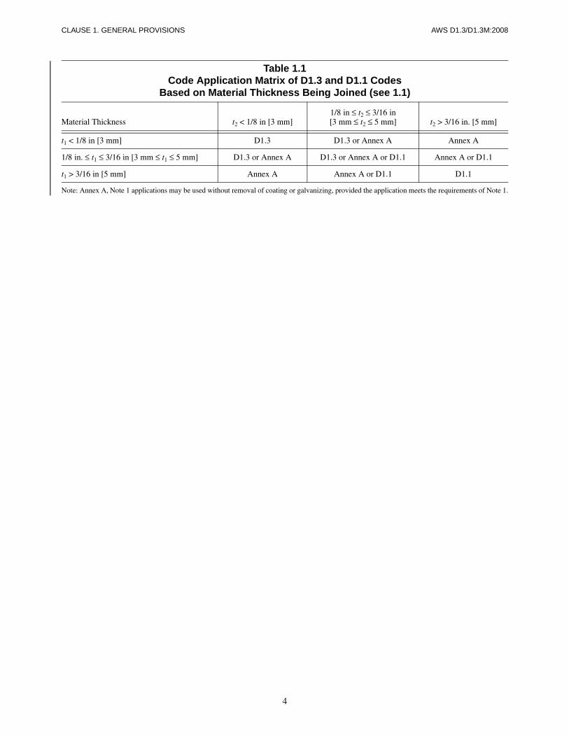
This code contains the requirements for arc welding ofstructural sheet/strip steels, including cold formed mem-bers, hereafter collectively referred to as “sheet steel,”which are equal to or less than 3/16 in (0.188 in)[4.8 mm] in nominal thickness. When this code is stipu-lated in contract documents, conformance with all itsprovisions shall be required, except for those provisionsthat the Engineer or contract documents specificallymodifies or exempts.
When used in conjunction with AWS D1.1, conformancewith the applicable provisions of Annex A of AWS D1.3shall apply (see also Table 1.1). Two weld types uniqueto sheet steel, arc spot, and arc seam are included in thiscode.
1.1.1 Applicable Materials. This code is applicable tothe welding of structural sheet steels to other structuralsheet steels or to supporting structural steel members.
1.1.2 General Stipulations. The fundamental premise ofthe code is to provide general stipulations applicable toany situation. Acceptance criteria for production weldsdifferent from those specified in the code shall be permit-ted for a particular application, provided they are suit-ably documented by the proposer and approved by theEngineer. These alternate acceptance criteria shall bebased upon evaluation of suitability for service usingpast experience, experimental evidence, or engineeringanalysis considering material type, service load effects,and environmental factors.
1.1.3 Approval. All references to the need for approvalshall be interpreted to mean approval by the Engineer,defined as the duly designated person who acts for and inbehalf of the owner on all matters within the scope of thiscode. Deviations from code requirements shall requirethe Engineer’s approval.
1.2 Sheet Steel Base Metal
1.2.1 Specified Base Metals. Sheet steel base metals tobe welded under this code shall conform to the require-ments of the latest edition of one of the specificationslisted in Table 1.2, or any sheet steel qualified in con-formance with 1.2.2. Any combination of these steelsmay be welded together. These steels may also bewelded to any of the steels listed in the latest edition ofAWS D1.1, Structural Welding Code—Steel.
1.2.2 Other Base Metals. When a steel other than thosecovered in 1.2.1 is approved under the provisions of theproject or product specification, and such a steel is pro-posed for welded construction, the weldability of thesteel and the WPS for welding it shall be established byqualification in conformance with the requirements ofClause 4 and such other requirements as prescribed bythe Engineer.
1.2.3 Minimum Yield Point. The provisions of this codeare intended for use with sheet steel having a minimumspecified yield point equal to or less than 80 ksi [550 MPa].
1.3 Welding Processes
1.3.1 Approved Processes. This code provides for weld-ing with the shielded metal arc welding (SMAW), gasmetal arc welding (GMAW), flux cored arc welding(FCAW), gas tungsten arc welding (GTAW), or sub-merged arc welding (SAW) welding processes. (NOTE:Any variation of gas metal arc welding (GMAW), includ-ing short-circuiting transfer, is acceptable.)
1.3.2 Stud Welding. When stud welding through the flatportion of sheet steel decking or roofing onto other prod-uct forms, the WPS, the studs, and the quality controlrequirements shall conform with the applicable provi-sions in the AWS D1.1 code.
1. General Provisions
Structural Welding Code—Sheet Steel
CLAUSE 1. GENERAL PROVISIONS AWS D1.3/D1.3M:2008
2
1.3.3 Other Processes. Other welding processes may beused when approved by the Engineer. In such case, theEngineer shall specify any additional qualification re-quirements necessary to assure satisfactory joints for theintended service.
1.4 Weld Metal Requirements1.4.1 Matching Filler Metals. When using the indicatedweld process, the filler metals listed in Table 1.2 providea weld joint with strengths matching that of the basemetal.
1.4.2 Other Base Metal–Filler Metal Combinations.Base metal–filler metal combinations other than thosedescribed in 1.4.1 shall be permitted when evaluated andapproved by the Engineer. When base metals of dissimi-lar strengths are welded, the filler metal tensile strengthshall be equal to or greater than that of the lowest tensilestrength base metal.
1.4.3 Manufacturer’s Certification. When requestedby the Engineer, the contractor shall furnish an electrodemanufacturer’s certification stating that the electrode willmeet the requirements of the classification.
1.4.4 Electrodes for Shielded Metal Arc Welding(SMAW)
1.4.4.1 AWS Specification. Electrodes for SMAWshall conform to the requirements of the latest edition ofAWS A5.1/A5.1M, Specification for Carbon Steel Elec-trodes for Shielded Metal Arc Welding, or to the require-ments of AWS A5.5/A5.5M, Specification for Low-AlloySteel Electrodes for Shielded Metal Arc Welding.
1.4.4.2 Low-Hydrogen Electrode Control. Thiscontrol shall be for sheet steel that is welded to a primarystructural member which is thicker than 1/4 in [6.4 mm],placing the jurisdiction of this control as specified inAWS D1.1.
1.4.5 Submerged Arc Welding (SAW)
1.4.5.1 AWS Specification. The bare electrodes andfluxes used in combination for SAW shall conform to therequirements of the latest edition of AWS A5.17/A5.17M,Specification for Carbon Steel Electrodes and Fluxes forSubmerged Arc Welding, or to the requirements of thelatest edition of AWS A5.23/A5.23M, Specification forLow-Alloy Steel Electrodes and Fluxes for SubmergedArc Welding.
1.4.5.2 Flux. Flux used for submerged arc weldingshall be dry and free of contamination from dirt, millscale, oils, or other foreign material. All flux shall bepurchased in packages that can be stored, under normal
conditions, for at least six months without such storageaffecting its welding characteristics or weld properties.Flux from damaged packages shall be discarded or shallbe dried at a minimum temperature of 250°F [120°C] forone hour before use. Flux shall be placed in the dispens-ing system immediately upon the opening of a package,or if used from an opened package, the top 1 in [25 mm]shall be discarded. Flux that has been wet shall not beused.
1.4.6 Gas Metal Arc Welding, Flux Cored Arc Weld-ing (FCAW), and Gas Tungsten Arc Welding(GTAW) Filler Metals
1.4.6.1 AWS Specification. The filler metals andshielding for GMAW, FCAW, or GTAW shall conformto the requirements of the latest edition of AWSA5.18/A5.18M, Specification for Carbon Steel Elec-trodes and Rods for Gas Metal Arc Welding, or AWSA5.28/A5.28M, Specification for Low-Alloy Steel Elec-trodes and Rods for Gas Shielded Arc Welding, AWSA5.20/A5.20M, Specification for Carbon Steel Elec-trodes for Flux Cored Arc Welding, or AWSA5.29/A5.29M, Specification for Low-Alloy Steel Elec-trodes for Flux Cored Arc Welding, as applicable.
1.4.6.2 Shielding Media. A gas or gas mixture usedfor shielding in GMAW, FCAW when required, orGTAW, shall meet the requirements of AWS A5.32/A5.32M, Specification for Welding Shielding Gases.When requested by the Engineer, the gas manufacturershall furnish certification that the gas or gas mixturemeets the requirements of AWS A5.32/A5.32M.
1.5 Weld Types1.5.1 Square-Groove Welds in Butt Joints. This typeof weld is restricted to the welding of sheet steel to sheetsteel in all positions of welding.
1.5.2 Fillet Welds. This type of weld may be used in allpositions of welding involving sheet steel to sheet steelor a sheet steel to a supporting structural member.
1.5.2.1 Fillet Welds in Lap and T-Joints. Filletwelds in lap and T-joints may be used in all positions(see Table 1.3) involving a sheet steel to sheet steel or asheet steel to a supporting structural member.
NOTE: When fillet welding sheet steel to a supportingstructural member, measures shall be taken to preventunderbead cracking.
1.5.3 Flare-Groove Welds. This type of weld may beused in all positions involving the following:
(1) Two sheet steels for flare-V and flare-bevel grooves
AWS D1.3/D1.3M:2008 CLAUSE 1. GENERAL PROVISIONS
3
(2) A sheet and a supporting structural member forflare-bevel groove (see Table 1.3)
1.5.4 Arc Spot Welds. This type of weld is a spot weldmade by an arc welding process in which the weld ismade without preparing a hole in either member. Thesewelds are restricted to the welding of sheet steel to sup-porting structural member in the flat position (see Table1.3). NOTE: Neither the thickness of a single sheet northe combined thickness of two sheets welded to thethicker supporting structural members shall exceed0.15 in [3.7 mm].
1.5.5 Arc Seam Welds. An arc seam weld is made with-out preparing a slot in either member.
These welds are restricted to the welding of jointsinvolving:
(1) Sheet to sheet in the flat or horizontal position
(2) Sheet to thicker supporting structural member inthe flat position (see Table 1.3)
1.5.6 Arc Plug Welds. An arc plug weld is made by fill-ing a circular hole in an outer member or members.
These welds may be used in all positions involving thefollowing:
(1) Multiple layers of sheet steels
(2) Multiple layers of sheet steels and a thicker sup-porting structural member
1.6 Terms and DefinitionsThe welding terms used in this specification shall beinterpreted in accordance with definitions given in thelatest edition of AWS A3.0, Standard Welding Termsand Definitions, supplemented by Annex D of thisspecification.
1.7 Welding SymbolsThe welding symbols used in this specification shall bethose designated in the latest edition of AWS A2.4, Stan-dard Symbols for Welding, Brazing, and NondestructiveExamination. Special conditions shall be fully explainedby notes or details.
1.8 Safety PrecautionsThe safety precautions shall conform to the latest editionof ANSI Z49.1, Safety in Welding, Cutting, and AlliedProcesses, published by the American Welding Society.
NOTE: Work performed to this code may involve hazard-ous operations and materials, such as fumes and solidparticles originating from welding consumables, thebase metal, and coatings present on the base metal. Thecode does not purport to address all safety concernsassociated with its use. It is the responsibility of the userto establish appropriate safety and health practices. Theuser should determine the applicability of any regulatorylimitations prior to use.
See Annex F for additional information relating to thebasic elements of safety general to arc welding processes.
1.9 Standard Units of MeasurementThis standard makes use of both U.S. Customary Unitsand the International System of Units (SI). The latter areshown within brackets [ ] or in appropriate columns intable and figures. The measurements may not be exactequivalents; therefore, each system must be used inde-pendently. Equivalents for gages or fractions are notedwithin parenthesis throughout the standard.
4
CLAUSE 1. GENERAL PROVISIONS AWS D1.3/D1.3M:2008
Table 1.1Code Application Matrix of D1.3 and D1.1 Codes
Based on Material Thickness Being Joined (see 1.1)
Material Thickness t2 < 1/8 in [3 mm]1/8 in ≤ t2 ≤ 3/16 in[3 mm ≤ t2 ≤ 5 mm] t2 > 3/16 in. [5 mm]
t1 < 1/8 in [3 mm] D1.3 D1.3 or Annex A Annex A
1/8 in. ≤ t1 ≤ 3/16 in [3 mm ≤ t1 ≤ 5 mm] D1.3 or Annex A D1.3 or Annex A or D1.1 Annex A or D1.1
t1 > 3/16 in [5 mm] Annex A Annex A or D1.1 D1.1
Note: Annex A, Note 1 applications may be used without removal of coating or galvanizing, provided the application meets the requirements of Note 1.

5
AWS D1.3/D1.3M:2008 CLAUSE 1. GENERAL PROVISIONS
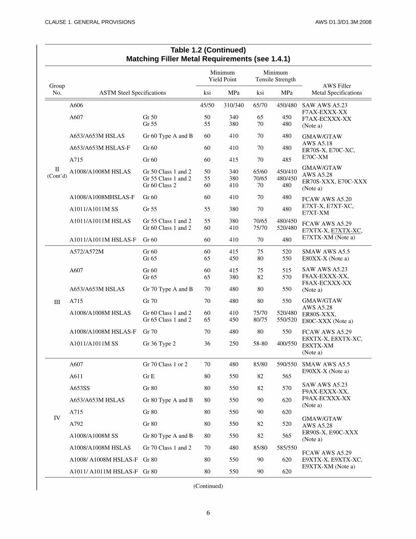
Table 1.2Matching Filler Metal Requirements (see 1.4.1)
GroupNo. ASTM Steel Specifications
MinimumYield Point
MinimumTensile Strength
AWS FillerMetal Specificationsksi MPa ksi MPa
I
A109 Temper 4 48 330 SMAW AWS A5.1E60XX, E70XX
SMAW AWS A5.5E70XX-XX (Note a)
SAW AWS A5.17F6AX-EXXX,F7AX-EXXX,F6AX-ECXXX,F7AX-ECXXX
SAW AWS A5.23F7AX-EXXX-XX,F7AX-ECXX-XX(Note a)
GMAW/GTAWAWS A5.18ER70S-X, E70C-XC,E70C-XM
GMAW/GTAWAWS A5.28ER70S-XXX,E70C-XXX(Note a)
FCAW AWS A5.20E7XT-X, E7XT-XC,E7XT-XM
FCAW AWS A5.29E6XTX-X, E6XTX-XC, E7XTX-X, E7XTX-XC, E6XTX-XM, E7XTX-XM(Note a)
A570/A570M Gr 30Gr 33Gr 36Gr 40Gr 45
3033364045
205230250275310
4952535560
340360365380415
A572/A572M Gr 42 42 290 60 415
A607 Gr 45 45 310 65 450
A611 Gr AGr BGr C Type 1Gr D Type 1
25303340
170205230275
42454852
290310330360
A653/A653M SS Gr 33Gr 37Gr 40
333740
230255275
455255
310360380
A653/A653M HSLAS Gr 50 Type A and B 50 340 60 410
A715 Gr 50 50 345 60 415
A792/A792M Gr 33Gr 37Gr 40
333740
230255275
455255
310360380
A1008/A1008M SS Gr 25Gr 30Gr 33 Type 1Gr 40 Type 1
25303340
170205230275
42454852
290310330360
A1008/A1008M HSLAS Gr 45 Class 1 and 2 45 310 55/60 380/410
A1008/A1008M HSLAS-F Gr 50 50 340 60 410
A1011/A1011M SS Gr 30Gr 33Gr 36 Type 1Gr 40Gr 45
3033364045
205230250275310
4952535560
340360365380410
A1011/A1011M HSLAS Gr 45 Class 1 and 2Gr 50 Class 2
4550
310340
55/6060
380/410410
A1011/A1011M HSLAS-F Gr 50 50 340 60 410
II
A109 Temper 3 55 380 SMAW AWS A5.1E70XX
SMAW AWS A5.5E70XX-X(Note a)
SAW AWS A5.17F7AX-EXXX,F7AX-ECXXX
A529/A529M Gr 50Gr 55
5055
345380
7070
485485
A570/A570M Gr 50Gr 55
5055
345380
6570
450480
A572/A572M Gr 50Gr 55
5055
345380
6570
450480
(Continued)
6
CLAUSE 1. GENERAL PROVISIONS AWS D1.3/D1.3M:2008
Table 1.2 (Continued)Matching Filler Metal Requirements (see 1.4.1)
GroupNo. ASTM Steel Specifications
MinimumYield Point
MinimumTensile Strength
AWS FillerMetal Specificationsksi MPa ksi MPa
II(Cont’d)
A606 45/50 310/340 65/70 450/480 SAW AWS A5.23F7AX-EXXX-XXF7AX-ECXXX-XX(Note a)
GMAW/GTAWAWS A5.18ER70S-X, E70C-XC,E70C-XM
GMAW/GTAWAWS A5.28ER70S-XXX, E70C-XXX(Note a)
FCAW AWS A5.20E7XT-X, E7XT-XC,E7XT-XM
FCAW AWS A5.29E7XTX-X, E7XTX-XC,E7XTX-XM (Note a)
A607 Gr 50Gr 55
5055
340380
6570
450480
A653/A653M HSLAS Gr 60 Type A and B 60 410 70 480
A653/A653M HSLAS-F Gr 60 60 410 70 480
A715 Gr 60 60 415 70 485
A1008/A1008M HSLAS Gr 50 Class 1 and 2Gr 55 Class 1 and 2Gr 60 Class 2
505560
340380410
65/6070/65
70
450/410480/450
480
A1008/A1008MHSLAS-F Gr 60 60 410 70 480
A1011/A1011M SS Gr 55 55 380 70 480
A1011/A1011M HSLAS Gr 55 Class 1 and 2Gr 60 Class 1 and 2
5560
380410
70/6575/70
480/450520/480
A1011/A1011M HSLAS-F Gr 60 60 410 70 480
III
A572/A572M Gr 60Gr 65
6065
415450
7580
520550
SMAW AWS A5.5E80XX-X (Note a)
SAW AWS A5.23F8AX-EXXX-XX,F8AX-ECXXX-XX(Note a)
GMAW/GTAWAWS A5.28ER80S-XXX,E80C-XXX (Note a)
FCAW AWS A5.29E8XTX-X, E8XTX-XC, E8XTX-XM(Note a)
A607 Gr 60Gr 65
6065
415380
7582
515570
A653/A653M HSLAS Gr 70 Type A and B 70 480 80 550
A715 Gr 70 70 480 80 550
A1008/A1008M HSLAS Gr 60 Class 1 and 2Gr 65 Class 1 and 2
6065
410450
75/7080/75
520/480550/520
A1008/A1008M HSLAS-F Gr 70 70 480 80 550
A1011/A1011M SS Gr 36 Type 2 36 250 58-80 400/550
IV
A607 Gr 70 Class 1 or 2 70 480 85/80 590/550 SMAW AWS A5.5E90XX-X (Note a)
SAW AWS A5.23F9AX-EXXX-XX,F9AX-ECXXX-XX(Note a)
GMAW/GTAWAWS A5.28ER90S-X, E90C-XXX(Note a)
FCAW AWS A5.29E9XTX-X, E9XTX-XC,E9XTX-XM (Note a)
A611 Gr E 80 550 82 565
A653SS Gr 80 80 550 82 570
A653/A653M HSLAS Gr 80 Type A and B 80 550 90 620
A715 Gr 80 80 550 90 620
A792 Gr 80 80 550 82 520
A1008/A1008M SS Gr 80 Type A and B 80 550 82 565
A1008/A1008M HSLAS Gr 70 Class 1 and 2 70 480 85/80 585/550
A1008/ A1008M HSLAS-F Gr 80 80 550 90 620
A1011/ A1011M HSLAS-F Gr 80 80 550 90 620
(Continued)
7
AWS D1.3/D1.3M:2008 CLAUSE 1. GENERAL PROVISIONS
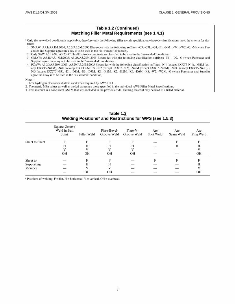
Table 1.2 (Continued)Matching Filler Metal Requirements (see 1.4.1)
a Only the as-welded condition is applicable, therefore only the following filler metals specification electrode classifications meet the criteria for thistable:1. SMAW: A5.1/A5.1M:2004; A5.5/A5.5M:2006 Electrodes with the following suffixes: -C3, -C3L, -C4, -P1, -NM1, -W1, -W2, -G, -M (when Pur-
chaser and Supplier agree the alloy is to be used in the “as-welded” condition).2. Only SAW A5.17-97; A5.23-97 Flux/Electrode combinations classified to be used in the “as-welded” condition.3. GMAW: A5.18/A5.18M;2005; A5.28/A5.28M:2005 Electrodes with the following classification suffixes: -Ni1, -D2, -G (when Purchaser and
Supplier agree the alloy is to be used in the “as-welded” condition).4. FCAW: A5.20/A5.20M:2005; A5.29/A5.29M:2005 Electrodes with the following classification suffixes: -Ni1 (except EXXT5-Ni1), -Ni1M (ex-
cept EXXT5-Ni1M), -Ni1C (except EXXT5-Ni1C), -Ni2 (except EXXT5-Ni2), -Ni2M (except EXXT5-Ni2M), -Ni2C (except EXXT5-Ni2C), -Ni3 (except EXXT5-Ni3), -D1, -D1M, -D3, -D3M, -K1, -K1M, -K2, -K2M, -K6, -K6M, -K8, -W2, -W2M, -G (when Purchaser and Supplieragree the alloy is to be used in the “as-welded” condition).
Notes:1. Low hydrogen electrodes shall be used when required by AWS D1.1.2. The metric MPa values as well as the ksi values are those specified in the individual AWS Filler Metal Specifications.3. This material is a noncurrent ASTM that was included in the previous code. Existing material may be used as a listed material.
Table 1.3Welding Positionsa and Restrictions for WPS (see 1.5.3)
Square-GrooveWeld in Butt
Joint Fillet WeldFlare-Bevel-Groove Weld
Flare-V-Groove Weld
ArcSpot Weld
ArcSeam Weld
ArcPlug Weld
Sheet to Sheet FHV
OH
FHV
OH
FHV
OH
FHV
OH
————
FH——
FHV
OH
Sheet toSupportingMember
————
FHV
OH
FHV
OH
————
F———
F———
FHV
OH
a Positions of welding: F = flat, H = horizontal, V = vertical, OH = overhead.

This page is intentionally blank.
8
AWS D1.3/D1.3M:2008

AWS D1.3/D1.3M:2008
9
Part AAllowable Load Capacities
NOTE: For welds not designed to resist external loads,the Engineer may disregard the requirements of thissubclause.
Components to be Used in Design Formulae
P = Allowable load capacity (kips)
Fu = Specified minimum ultimate tensile strength ofsheet steel (ksi)
Fy = Specified minimum yield strength of sheet steel(ksi)
Fxx = Specified minimum tensile strength of AWS elec-trode classification (ksi)
Fw = Allowable weld shear stress 0.3 Fxx (ksi)
t = Thickness of sheet steel thinner member exclusiveof coatings (single sheet or combined multiplethicknesses of sheet steels) (in) [mm]
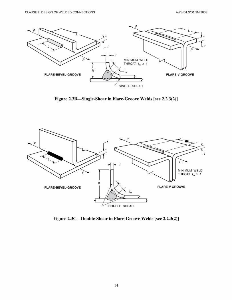
tw = Weld throat or size (see Figures 2.2, 2.3B, 2.3C,and Annex D for definitions of actual, effective,and theoretical throat of a fillet weld, and for thedefinition of groove weld size) (in) [mm].
L = Length of weld—for fillet, flare-groove, or arcseam welds (in) [mm]
NOTE: For arc seam welds the L dimension doesnot include the circular ends (see Figure 2.5)
h = Lip height—for flare-groove welds (see Figures2.3B and 2.3C) (in) [mm]
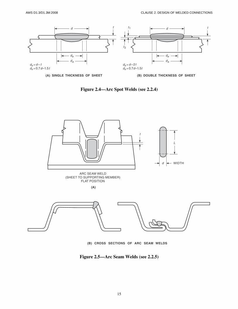
d = Visible diameter of the weld face of arc spotwelds or arc plug welds (see Figures 2.4 and 2.6)or the visible width of arc seam welds (see Figure2.5) (in) [mm]
da = Resultant average diameter of an arc spot weld orarc plug weld (see Figures 2.4 and 2.6) or an aver-
age width of an arc seam weld (see Figure 2.5)(in) [mm]
de = Effective diameter of an arc spot weld or arc plugweld or an effective width of an arc seam weld atthe faying surface (see Figures 2.4, 2.5, and 2.6)(in) [mm]
NOTE: If it can be shown by sectioning and measuringthat a WPS will consistently give a larger effective diam-eter (de) at the faying surface, this value may be usedproviding this particular WPS is used.
2.1 Base-Metal StressesThe allowable base-metal stresses shall be those speci-fied in the latest edition of the Specification for theDesign of Cold-Formed Steel Structural Members of theAmerican Iron and Steel Institute or as otherwise speci-fied in the applicable contract specifications.
2.2 Allowable Load Capacities in Weld Joints
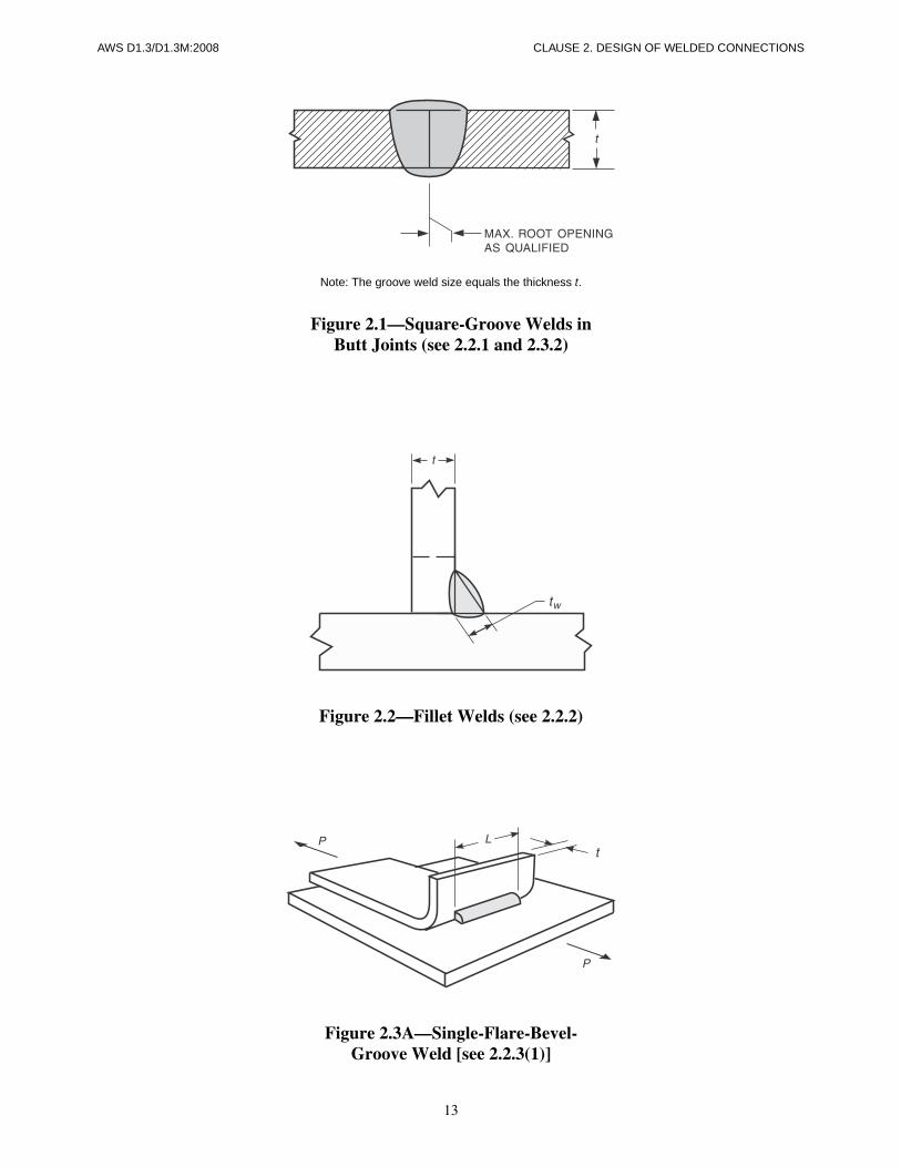
2.2.1 Square-Groove Welds in Butt Joints. The allow-able unit load capacities for matching electrode and basemetal combinations (see Table 1.2) for a groove weld ina butt joint, welded from one side or both sides, shall bethat of the lower strength base metal in the joint, pro-vided that the weld size is equal to the thickness of thebase metal (see Figure 2.1).
2.2.2 Fillet Welds. The allowable load capacity of a fil-let weld in lap and T-joints, made in any welding posi-tion (see Figure 2.2) for matching filler-metal base-metalcombinations (see Table 1.2), shall be governed by thethickness of the sheet steel, provided that tw is at leastequal to the thickness of the sheet steel. The allowableload capacity shall be the following:
2. Design of Welded Connections
CLAUSE 2. DESIGN OF WELDED CONNECTIONS AWS D1.3/D1.3M:2008
10
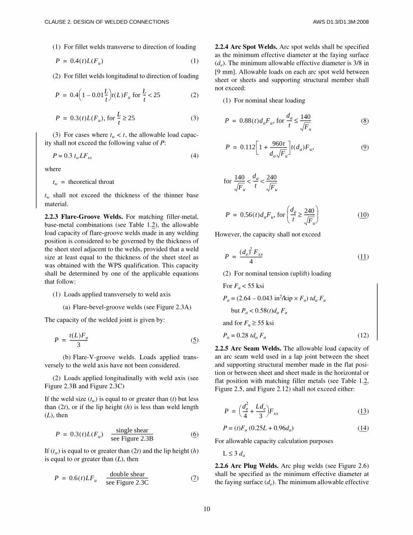
(1) For fillet welds transverse to direction of loading
(1)
(2) For fillet welds longitudinal to direction of loading
(2)
(3)
(3) For cases where tw < t , the allowable load capac-ity shall not exceed the following value of P:
P = 0.3 twLFxx (4)
where
tw = theoretical throat
tw shall not exceed the thickness of the thinner basematerial.
2.2.3 Flare-Groove Welds. For matching filler-metal,base-metal combinations (see Table 1.2), the allowableload capacity of flare-groove welds made in any weldingposition is considered to be governed by the thickness ofthe sheet steel adjacent to the welds, provided that a weldsize at least equal to the thickness of the sheet steel aswas obtained with the WPS qualification. This capacityshall be determined by one of the applicable equationsthat follow:
(1) Loads applied transversely to weld axis
(a) Flare-bevel-groove welds (see Figure 2.3A)
The capacity of the welded joint is given by:
(5)
(b) Flare-V-groove welds. Loads applied trans-versely to the weld axis have not been considered.
(2) Loads applied longitudinally with weld axis (seeFigure 2.3B and Figure 2.3C)
If the weld size (tw) is equal to or greater than (t) but lessthan (2t), or if the lip height (h) is less than weld length(L), then
(6)
If (tw) is equal to or greater than (2t) and the lip height (h)is equal to or greater than (L), then
(7)
P 0.4 t( )L Fu( )=
P 0.4 1 0.01Lt---–⎝ ⎠
⎛ ⎞ t L( )Fu for Lt--- 25<=
P 0.3 t( )L Fu( ), for Lt--- 25≥=
Pt L( )Fu
3----------------=
P 0.3 t( )L Fu( ) single shearsee Figure 2.3B-------------------------------------=
P 0.6 t( )LFu double shearsee Figure 2.3C-------------------------------------=
2.2.4 Arc Spot Welds. Arc spot welds shall be specifiedas the minimum effective diameter at the faying surface(de). The minimum allowable effective diameter is 3/8 in[9 mm]. Allowable loads on each arc spot weld betweensheet or sheets and supporting structural member shallnot exceed:
(1) For nominal shear loading
(8)
(9)
(10)
However, the capacity shall not exceed
(11)
(2) For nominal tension (uplift) loading
For Fu < 55 ksi
Pa = (2.64 – 0.043 in2/kip × Fu) tda Fu
but Pa < 0.58(t)da Fu
and for Fu ≥ 55 ksi
Pa = 0.28 tda Fu (12)
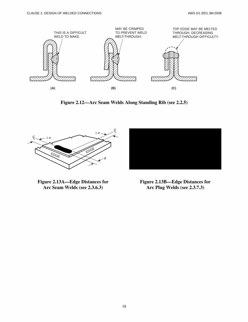
2.2.5 Arc Seam Welds. The allowable load capacity ofan arc seam weld used in a lap joint between the sheetand supporting structural member made in the flat posi-tion or between sheet and sheet made in the horizontal orflat position with matching filler metals (see Table 1.2,Figure 2.5, and Figure 2.12) shall not exceed either:
(13)
P = (t)Fu (0.25L + 0.96da) (14)
For allowable capacity calculation purposes
L ≤ 3 da
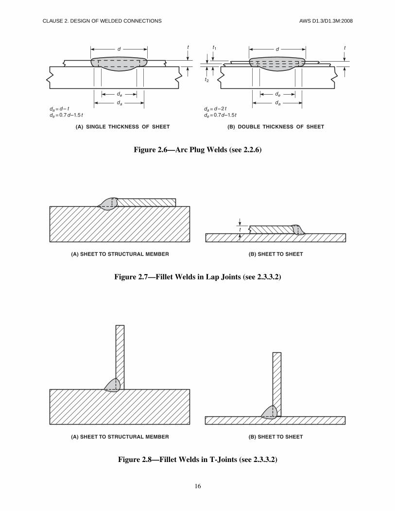
2.2.6 Arc Plug Welds. Arc plug welds (see Figure 2.6)shall be specified as the minimum effective diameter atthe faying surface (de). The minimum allowable effective
P 0.88 t( )daFu, for dat
----- 140Fu
----------≤=
P 0.112 1 960tda Fu
---------------+ t da( )Fu,=
for 140Fu
----------dat
----- 240Fu
----------< <
P 0.56 t( )daFu, for dat
----- 240Fu
----------≥⎝ ⎠⎜ ⎟⎛ ⎞
=
Pde( )2 Fxx
4--------------------=
Pde
2
4-----
Lde3
--------+⎝ ⎠⎛ ⎞Fxx=

AWS D1.3/D1.3M:2008 CLAUSE 2. DESIGN OF WELDED CONNECTIONS
11
diameter is 3/8 in [9 mm]. Allowable loads on each arcplug weld between sheet or sheets and supporting struc-tural member shall not exceed:
(1) For nominal shear loading
(15)
(16)
(17)
However, the capacity shall not exceed
(18)
(2) For nominal tension (uplift) loading
For Fu < 55 ksi
Pa = (2.64 – 0.043 in2/kip × Fu) tda Fu
but Pa < 0.58(t)da Fu
and for Fu ≥ 55 ksi
Pa = 0.28 tda Fu (19)
Part BDetails of Welded Connections
2.3.1 General. Welded joints may be made using square-groove welds in butt joints, arc spot or arc seam welds inlap joints, or fillet welds in lap or T-joints, and single-flare-bevel or single-flare-V groove welds in butt, lap, orT-joints when they are within the applicable limitationsof 2.3.2 through 2.3.5.
2.3.2 Square-Groove Welds. Square-groove welds shallbe used in butt joints per Table 1.3 (see Figure 2.1).
2.3.3 Fillet Welds
2.3.3.1 Minimum Length. Minimum length shall be3/4 in [19 mm].
2.3.3.2 Leg Sizes. Leg sizes of lap joint fillet weldsshall be equal to the thickness of the thinner sheet steel(see Figure 2.7). The leg size of the T-joint fillet welds
P 0.88 t( )daFu, for dat
----- 140Fu
----------≤=
P 0.112 1 960tdaFu-----------+ t da( )Fu,=
for 140Fu
----------dat
----- 240< Fu
-------------< <
P 0.56 t( )daFu, for dat
----- 240Fu
----------≥=
Pde( )2 Fxx
4--------------------=
shall be equal to the thickness of the thinnest sheet steel(t) (see Figure 2.8).
2.3.4 Flare-Groove Welds
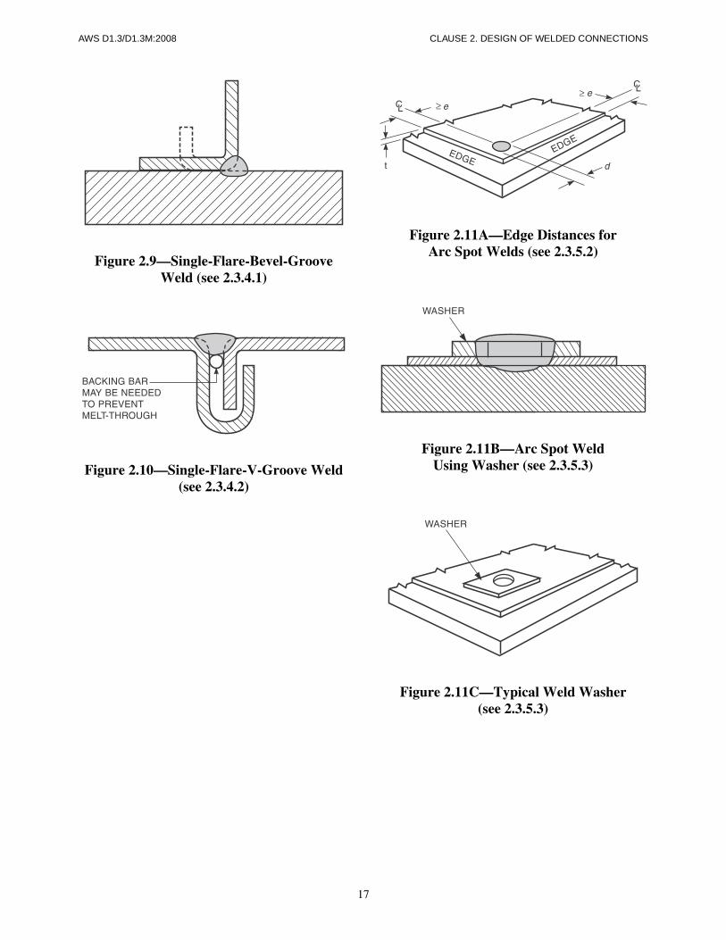
2.3.4.1 Single-Flare-Bevel-Groove Welds. Single-flare-bevel-groove weld positions shall be per Table 1.3.The minimum length shall be 3/4 in [19 mm] (see Figure2.9).
2.3.4.2 Single-Flare-V-Groove Welds. Single-flare-V-groove weld positions shall be per Table 1.3. The min-imum length shall be 3/4 in [19 mm] (see Figure 2.10).
2.3.5 Arc Spot Welds
2.3.5.1 Single or Double Thicknesses. The positionsof arc spot welds made through one or double thick-nesses of sheet steel onto a supporting member shall beper Table 1.3. The arc spot welds are restricted to onlythe flat position (see Figure 2.4). The WPS weld metaldiameter (de) at the fusion surface shall be at least 3/8 in[9 mm].
2.3.5.2 Minimum Edge Distance. The minimum dis-tance (e) from the center of an arc spot weld to any edgeof the sheet steel shall not be less than
(20)
or
(21)
but not less than 1.5d (see Figure 2.11A).
2.3.5.3 Weld Washers. Weld washers are to be usedin containing the arc spot welds in sheet steel thinnerthan 0.028 in [0.7 mm] to prevent burnback (see Figures2.11B and 2.11C). Weld washers shall be made of one ofthe sheet steels listed in 1.2.1 and shall have a thicknessbetween 0.05 in and 0.08 in [1.3 mm and 2.1 mm], with aminimum prepunched hole diameter of 3/8 in [9 mm].
2.3.6 Arc Seam Welds
2.3.6.1 Positions. Arc seam welds between sheetsteels or between sheet steel and supporting membersshall be per Table 1.3.
2.3.6.2 Minimum Width. The minimum width ofweld metal at the faying surface of arc seam welds shallbe 3/8 in [9 mm].
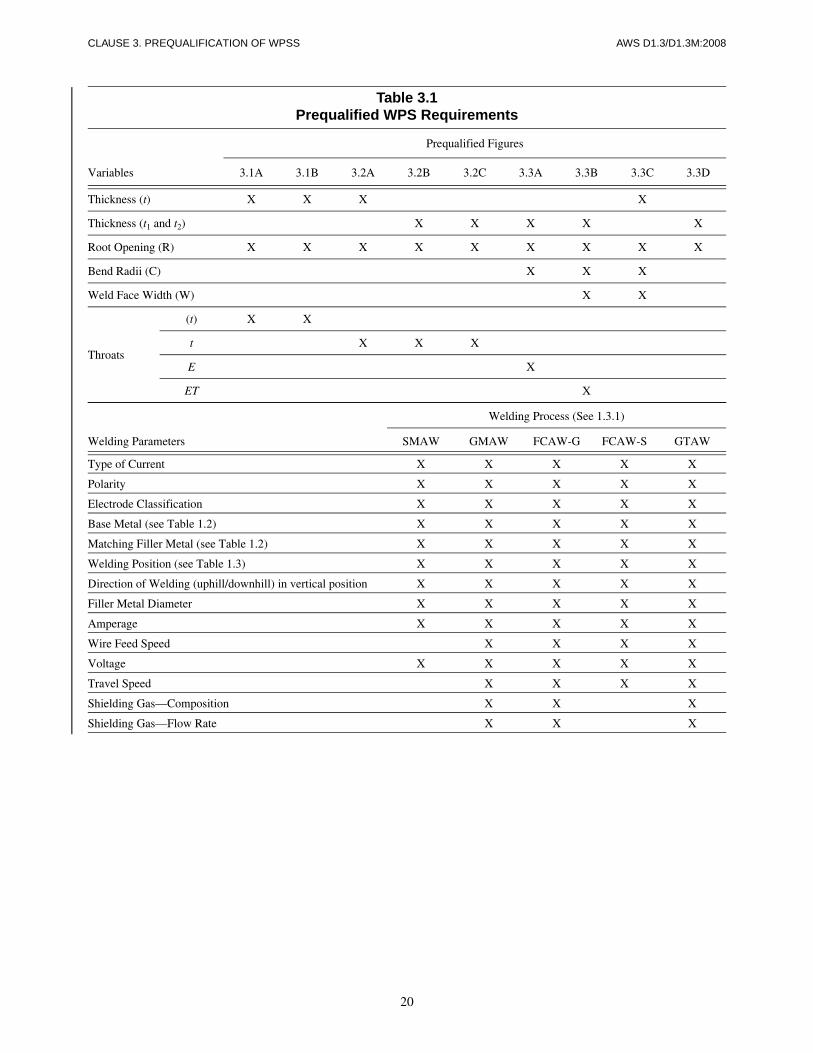
2.3.6.3 Minimum Edge Distance. The distance fromthe end of the arc seam weld to the edge of the sheet steelshall be measured from the center of the circular portionof the weld (see Figure 2.13A). The minimum distance
eminP
0.5Fut--------------- , for
FuFy----- 1.15≥=
eminP
0.45Fut------------------ , for
FuFy----- < 1.15=

CLAUSE 2. DESIGN OF WELDED CONNECTIONS AWS D1.3/D1.3M:2008
12
from the longitudinal axis of an arc seam weld or fromthe end of an arc seam weld to the edge of the sheet steelshall not be less than that obtained when using the equa-tion in 2.3.5.2, but not less than 1.5d (see Figures 2.5 and2.12).
2.3.7 Arc Plug Welds
2.3.7.1 Position and WPS Diameter. The position ofarc plug welds shall be per Table 1.3 (see Figure 2.6).The WPS weld metal diameter (de) at the fusion surfaceshall be at least 3/8 in [9 mm].
2.3.7.2 Minimum Hole Diameter. For sheet steelthicknesses equal to or less than 20 gage [0.912 mm], thehole shall be 1/4 in [6.4 mm] minimum diameter; forthicknesses greater than 20 gage the hole shall be 5/16 in[8.0 mm] diameter. For multiple thicknesses using arc
plug welds, the holes may have to be enlarged to attainthe weld metal minimum diameter (de) of 3/8 in [9 mm]at the fusion surface.
2.3.7.3 Minimum Edge Distance. The minimum dis-tance (e) from the center of an arc plug weld to any edgeof the sheet steel shall not be less than
(22)
or
(23)
but not less than 1.5d (see Figure 2.13B).
eminP
0.5Fut--------------- , for
FuFy----- 1.15≤=
eminP
0.45Fut------------------ , for
FuFy----- < 1.15=
13
AWS D1.3/D1.3M:2008 CLAUSE 2. DESIGN OF WELDED CONNECTIONS
Note: The groove weld size equals the thickness t.
Figure 2.1—Square-Groove Welds inButt Joints (see 2.2.1 and 2.3.2)
Figure 2.2—Fillet Welds (see 2.2.2)
Figure 2.3A—Single-Flare-Bevel-Groove Weld [see 2.2.3(1)]
14
CLAUSE 2. DESIGN OF WELDED CONNECTIONS AWS D1.3/D1.3M:2008
Figure 2.3B—Single-Shear in Flare-Groove Welds [see 2.2.3(2)]
Figure 2.3C—Double-Shear in Flare-Groove Welds [see 2.2.3(2)]
15
AWS D1.3/D1.3M:2008 CLAUSE 2. DESIGN OF WELDED CONNECTIONS
Figure 2.4—Arc Spot Welds (see 2.2.4)
Figure 2.5—Arc Seam Welds (see 2.2.5)
16
CLAUSE 2. DESIGN OF WELDED CONNECTIONS AWS D1.3/D1.3M:2008
Figure 2.6—Arc Plug Welds (see 2.2.6)
Figure 2.7—Fillet Welds in Lap Joints (see 2.3.3.2)
Figure 2.8—Fillet Welds in T-Joints (see 2.3.3.2)
17
AWS D1.3/D1.3M:2008 CLAUSE 2. DESIGN OF WELDED CONNECTIONS
Figure 2.9—Single-Flare-Bevel-Groove Weld (see 2.3.4.1)
Figure 2.10—Single-Flare-V-Groove Weld (see 2.3.4.2)
Figure 2.11A—Edge Distances forArc Spot Welds (see 2.3.5.2)
Figure 2.11B—Arc Spot WeldUsing Washer (see 2.3.5.3)
Figure 2.11C—Typical Weld Washer(see 2.3.5.3)
18
CLAUSE 2. DESIGN OF WELDED CONNECTIONS AWS D1.3/D1.3M:2008
Figure 2.12—Arc Seam Welds Along Standing Rib (see 2.2.5)
Figure 2.13A—Edge Distances forArc Seam Welds (see 2.3.6.3)
Figure 2.13B—Edge Distances forArc Plug Welds (see 2.3.7.3)

AWS D1.3/D1.3M:2008
19
3.0 ScopePrequalification of WPSs (Welding Procedure Specifica-tions) shall be defined as exemption from the WPS qual-ification testing required in Clause 4. All prequalifiedWPSs shall be written. In order for a WPS to be prequal-ified, conformance with all of the applicable require-ments of Clause 3 shall be required. The provisions ofClause 3 apply only to welded connections betweensheet steel and sheet steel or sheet steel to a supportingstructural member with a base-metal thickness equal toor less than 3/16 in [5 mm].
3.1 General3.1.1 Requirements. A written WPS that includes arecorded value for each of the variable requirements asshown in Table 3.1, is designated as prequalified: Thiswritten WPS may follow any convenient format (seeAnnex A for example). Any change to any of therecorded values on this WPS requires either a new or arevised WPS be written.
3.2 Joint DetailsFor any departure from the joint details prescribed byFigures 3.1A through 3.3D, the contractor shall submit
the proposed WPSs to the Engineer for approval, anddemonstrate their adequacy in conformance with Clause4 and conformance with the applicable provisions ofClause 5.
3.2.1 Square Groove Welds in Butt Joints. Completejoint penetration groove welds (CJP) made by theSMAW, GMAW, GTAW, or FCAW processes in buttor corner joints, which may be used withoutWPS qualification tests, are detailed in Figures 3.1A and3.1B.
3.2.2 Fillet Welds. Fillet welds made by the SMAW,GMAW, GTAW, or FCAW processes, which may beused without WPS qualification tests, are detailed in Fig-ures 3.2A, 3.2B, and 3.2C.
3.2.3 Flare-Groove Welds in Butt or Corner Joints.Flare-groove welds made by the SMAW, GMAW,GTAW, or FCAW processes, which may be used with-out WPS qualification tests, are detailed in Figures 3.3A,3.3B, and 3.3C.
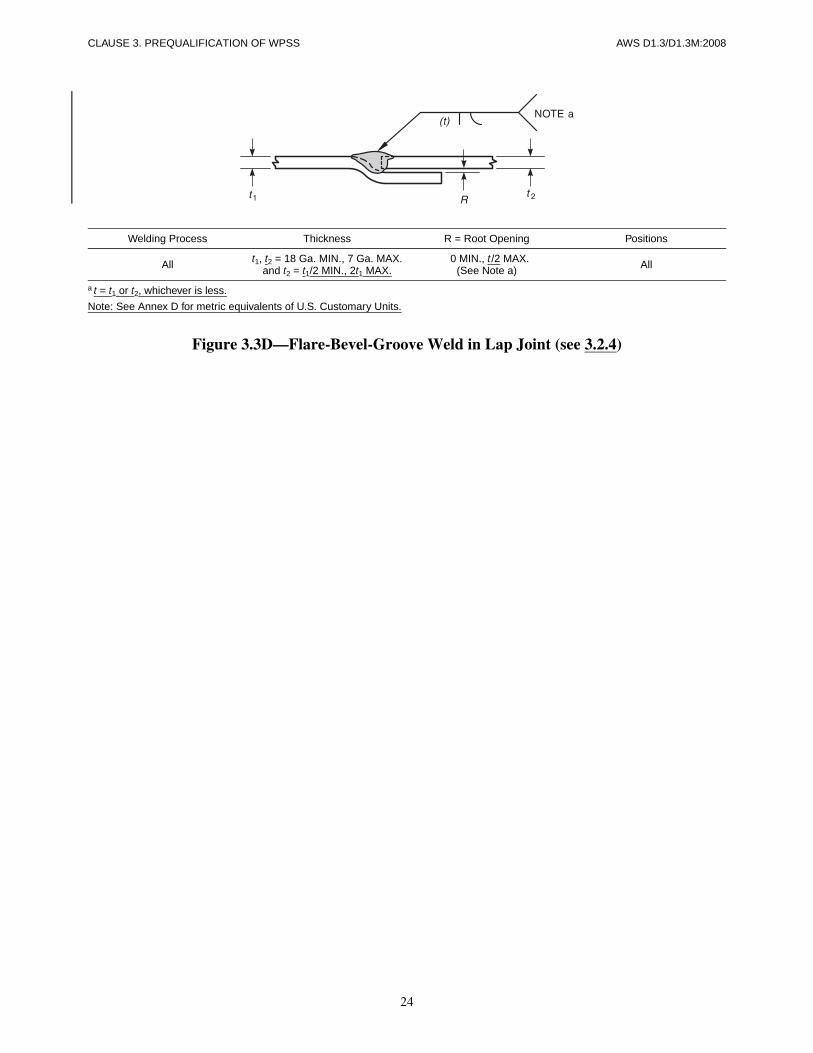
3.2.4 Flare-Bevel Groove Welds in Lap Joints. Flare-bevel groove welds made by the SMAW, GMAW,GTAW, or FCAW processes in lap joints, which maybe used without WPS qualification tests, are detailed inFigure 3.3D.
3. Prequalification of WPSs
20
CLAUSE 3. PREQUALIFICATION OF WPSS AWS D1.3/D1.3M:2008
Table 3.1Prequalified WPS Requirements
Variables
Prequalified Figures
3.1A 3.1B 3.2A 3.2B 3.2C 3.3A 3.3B 3.3C 3.3D
Thickness (t) X X X X
Thickness (t1 and t2) X X X X X
Root Opening (R) X X X X X X X X X
Bend Radii (C) X X X
Weld Face Width (W) X X
Throats
(t) X X
t X X X
E X
ET X
Welding Parameters
Welding Process (See 1.3.1)
SMAW GMAW FCAW-G FCAW-S GTAW
Type of Current X X X X X
Polarity X X X X X
Electrode Classification X X X X X
Base Metal (see Table 1.2) X X X X X
Matching Filler Metal (see Table 1.2) X X X X X
Welding Position (see Table 1.3) X X X X X
Direction of Welding (uphill/downhill) in vertical position X X X X X
Filler Metal Diameter X X X X X
Amperage X X X X X
Wire Feed Speed X X X X
Voltage X X X X X
Travel Speed X X X X
Shielding Gas—Composition X X X
Shielding Gas—Flow Rate X X X

21
AWS D1.3/D1.3M:2008 CLAUSE 3. PREQUALIFICATION OF WPSS
Note: See Annex D for metric equivalents of U.S. Customary Units.
Figure 3.1A—Square Groove Weld in Butt Joint with Steel Backing (see 3.2.1)
Note: See Annex D for metric equivalents of U.S. Customary Units.
Figure 3.1B—Square Groove Weld in Butt or Corner Joint without Backing (see 3.2.1)
Note: See Annex D for metric equivalents of U.S. Customary Units.
Figure 3.2A—Fillet Weld in Corner Joint (see 3.2.2)
Welding Process Thickness R = Root Opening Positions
All18 Ga. MIN., 16 Ga. MAX. 0 MIN., 3/4 t MAX.
All15 Ga. MIN., 7 Ga. MAX. 3/4 t MIN., 1-1/4 t MAX.
Welding Process Thickness R = Root Opening Positions
All18 Ga. MIN., 12 Ga. MAX. 0 MIN., t/2 MAX.
All11 Ga. MIN., 7 Ga. MAX. t/2 MIN., t MAX.
Welding Process Thickness R = Root Opening Positions
All 18 Ga. MIN., 11 Ga. MAX. 0 MIN., t/4 MAX. All
22
CLAUSE 3. PREQUALIFICATION OF WPSS AWS D1.3/D1.3M:2008
a t = t1 or t2, whichever is less.
Note: See Annex D for metric equivalents of U.S. Customary Units.
Figure 3.2B—Fillet Weld in Lap Joint (see 3.2.2)
a t = t1 or t2, whichever is less.
Note: See Annex D for metric equivalents of U.S. Customary Units.
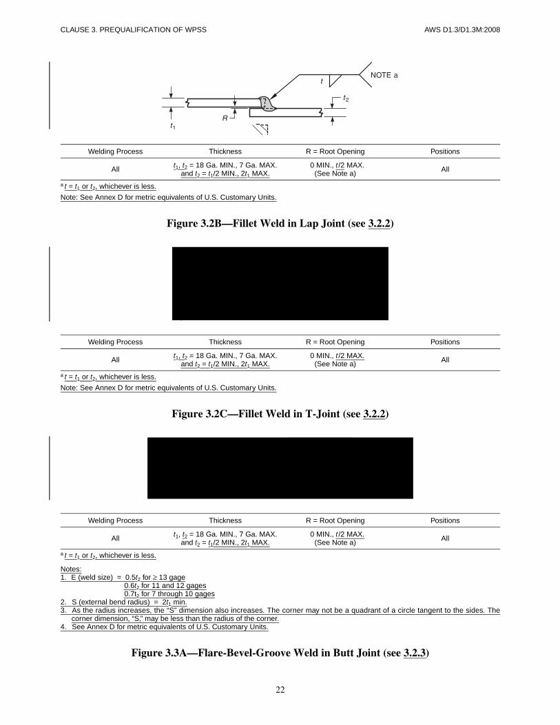
Figure 3.2C—Fillet Weld in T-Joint (see 3.2.2)
a t = t1 or t2, whichever is less.
Notes:1. E (weld size) = 0.5t2 for ≥ 13 gage
0.6t2 for 11 and 12 gages0.7t2 for 7 through 10 gages
2. S (external bend radius) = 2t1 min.3. As the radius increases, the “S” dimension also increases. The corner may not be a quadrant of a circle tangent to the sides. The
corner dimension, “S,” may be less than the radius of the corner.4. See Annex D for metric equivalents of U.S. Customary Units.
Figure 3.3A—Flare-Bevel-Groove Weld in Butt Joint (see 3.2.3)
Welding Process Thickness R = Root Opening Positions
All t1, t2 = 18 Ga. MIN., 7 Ga. MAX.and t2 = t1/2 MIN., 2t1 MAX.
0 MIN., t/2 MAX.(See Note a) All
Welding Process Thickness R = Root Opening Positions
All t1, t2 = 18 Ga. MIN., 7 Ga. MAX.and t2 = t1/2 MIN., 2t1 MAX.
0 MIN., t/2 MAX.(See Note a) All
Welding Process Thickness R = Root Opening Positions
All t1, t2 = 18 Ga. MIN., 7 Ga. MAX.and t2 = t1/2 MIN., 2t1 MAX.
0 MIN., t/2 MAX.(See Note a) All
23
AWS D1.3/D1.3M:2008 CLAUSE 3. PREQUALIFICATION OF WPSS
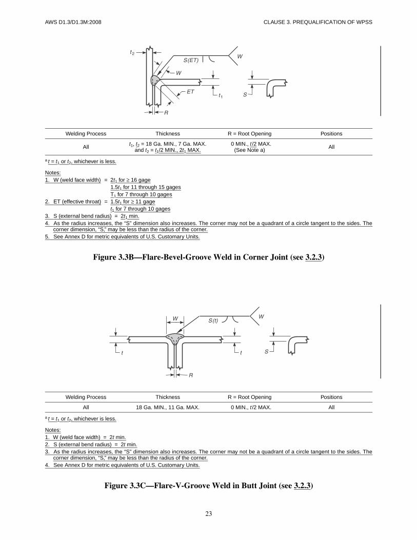
a t = t1 or t2, whichever is less.
Notes:1. W (weld face width) = 2t1 for ≥ 16 gage
1.5t1 for 11 through 15 gagesT1 for 7 through 10 gages
2. ET (effective throat) = 1.5t1 for ≥ 11 gaget1 for 7 through 10 gages
3. S (external bend radius) = 2t1 min.4. As the radius increases, the “S” dimension also increases. The corner may not be a quadrant of a circle tangent to the sides. The
corner dimension, “S,” may be less than the radius of the corner.5. See Annex D for metric equivalents of U.S. Customary Units.
Figure 3.3B—Flare-Bevel-Groove Weld in Corner Joint (see 3.2.3)
a t = t1 or t2, whichever is less.
Notes:1. W (weld face width) = 2t min.2. S (external bend radius) = 2t min.3. As the radius increases, the “S” dimension also increases. The corner may not be a quadrant of a circle tangent to the sides. The
corner dimension, “S,” may be less than the radius of the corner.4. See Annex D for metric equivalents of U.S. Customary Units.
Figure 3.3C—Flare-V-Groove Weld in Butt Joint (see 3.2.3)
Welding Process Thickness R = Root Opening Positions
All t1, t2 = 18 Ga. MIN., 7 Ga. MAX.and t2 = t1/2 MIN., 2t1 MAX.
0 MIN., t /2 MAX.(See Note a) All
Welding Process Thickness R = Root Opening Positions
All 18 Ga. MIN., 11 Ga. MAX. 0 MIN., t/2 MAX. All
24
CLAUSE 3. PREQUALIFICATION OF WPSS AWS D1.3/D1.3M:2008
a t = t1 or t2, whichever is less.
Note: See Annex D for metric equivalents of U.S. Customary Units.
Figure 3.3D—Flare-Bevel-Groove Weld in Lap Joint (see 3.2.4)
Welding Process Thickness R = Root Opening Positions
All t1, t2 = 18 Ga. MIN., 7 Ga. MAX.and t2 = t1/2 MIN., 2t1 MAX.
0 MIN., t/2 MAX.(See Note a) All

AWS D1.3/D1.3M:2008
25
Part AGeneral Requirements
4.1 Preparation of a WPS and PQR
A Welding Procedure Specification (WPS) shall be writ-ten for each type of weld as shown in Table 4.1, exceptas permitted in Clause 3, and shall be qualified inconformance with the provisions of Clause 4 by themanufacturer or contractor. A Procedure QualificationRecord (PQR) that records the actual values used to qual-ify a WPS shall be written. Suggested, nonmandatoryforms for WPSs and PQRs are given in Annex B. Note:Melting rate data of SMAW electrodes (see CommentaryC-4.6.4.2) may be used as a measure of welding currentfor the WPS and PQR.
4.2 Engineer’s Approval
Properly documented evidence of previous WPS qualifi-cation may be accepted with the Engineer’s approval.The Engineer may accept properly documented evidenceof previous qualification of the WPSs that are to beemployed. The acceptability of qualification to otherstandards is the Engineer’s responsibility, to be exercisedbased upon the specific structure, or service conditions,or both. AWS B2.1.XXX-XX Series on Standard Weld-ing Procedure Specifications may, in this manner, beaccepted for use in this code.
4.3 Responsibility
Each manufacturer or contractor shall be responsible forinspection and testing of WPS qualification test assem-blies in conformance with the provisions of Clause 4.
4.4 WPS RequirementsWPSs shall be qualified for each change in essential vari-ables as listed in 4.5.
Part BWelding Procedure Specification
(WPS)
4.5 Essential Variable LimitationsAny of the essential variable changes listed in Table 4.2shall require WPS requalification.
4.6 Number of Tests, Testing Methods, and Acceptance Standards for WPS Qualification
4.6.1 Square Groove Welds in Butt Joints
4.6.1.1 Qualification Testing. For a square-grooveweld in butt joint WPS not conforming to 3.2, qualifica-tion testing shall be required in conformance with Table4.2, Item (10)(b) or Table 4.2, Item (10)(c).
4.6.1.2 Test Assemblies and Examination. The testassembly shall conform to the following:
(1) Sheet steel shall be welded together as shown inFigure 4.1.
(2) The weld shall be uniform in appearance andshall be free of:
(a) cracks
(b) reinforcement not in conformance with 6.1.1.2
(c) undercut not in conformance with 6.1.1.3
4. Qualification
CLAUSE 4. QUALIFICATION AWS D1.3/D1.3M:2008
26
(3) The welded test sheets shall be hammered and bentthrough 180° (see Figure 4.1), the bend axis being coinci-dent with the weld axis. For joints welded from one sideonly, the root of the weld shall be on the face of the bend.
(4) A weld shall be acceptable if the following crite-ria are satisfied:
(a) No cracks are visually detected after bending,
or
(b) Weld metal cracks are visually detected and:
(i) The fractured face shows no visually de-tectable discontinuities (e.g., slag, porosity), and
(ii) The weld size is equal to or greater than thesheet steel thickness
NOTE: Base-metal cracks shall be ignored.
4.6.1.3 Qualification Ranges. A change in any one ofthe essential variables that exceed the limitations of 4.5requires requalification.
4.6.2 Fillet Welds
4.6.2.1 Qualification Testing. For a fillet weld WPSnot conforming to 3.3, qualification testing shall berequired in conformance with Table 4.2, Item (10)(b) orTable 4.2, Item (10)(c).
4.6.2.2 Test Assemblies and Examination. Two testassemblies shall be prepared, welded, visually inspected,and tested using either sheet to sheet or sheet to support-ing structural member described in (1) or (2) as follows:
(1) Sheet to Sheet. Each test assembly shall conformto Figure 4.2A.
(2) Sheet to Supporting Structural Member. Eachtest assembly shall conform to Figure 4.2A.
(3) Examination. A weld shall be acceptable if thefollowing criteria are satisfied:
(a) No weld metal cracks shall be visually detectedafter bending, or
(b) Weld metal cracks are visually detected afterbending and
(i) The fractured face shows no visually de-tectable discontinuities (e.g., slag, porosity), and
(ii) The weld size tw is equal to or greater thanthe sheet steel thickness
NOTE: Base-metal cracks shall be ignored.
(c) After visual inspection of acceptable welds, thetwo pieces shall be completely separated by either bend-ing the sheets or by hammering a wedge (see Figure4.2A) until either the weld or sheet metal fails.
(d) The fractured surface shall show complete fu-sion at the root of the joint.
4.6.2.3 Qualification Ranges. The validity of qualifi-cation shall be as follows (see Figure 4.2B):
(1) T-joints shall qualify for lap and T-joints.
(2) Sheet steel to supporting structural member quali-fies for sheet steel to supporting structural member for agiven position of welding and thickness of sheet steel.
(3) Sheet steel to sheet steel qualifies for sheet steelto sheet steel, and also sheet steel to supporting structuralmember for a given position of welding and thickness ofsheet steel. If there are two thicknesses of sheet steel, thethickness of the thinner sheet will control.
4.6.3 Flare-Groove Welds
4.6.3.1 Qualification Testing. For a flare-grooveweld WPS not conforming to 3.4, qualification testingshall be required in conformance with Table 4.2, Item(10)(b) or Table 4.2, Item (10)(c).
4.6.3.2 Test Assemblies and Examination. The fol-lowing requirements shall be met:
(1) Flare-Bevel-Groove Welds. Two test assembliesshall be required, conforming to either sheet to sheet orsheet to supporting structural member as follows:
(a) Sheet to Sheet. Each assembly shall consistof two rectangular pieces of sheet steel, at least 2-1/2 in[65 mm] wide, and at least 3 in [75 mm] long. One pieceshall be bent through 90° around an inside radius not toexceed 3t,where t is the thickness of sheet steel; the otherpiece shall be flat. These shall be fitted together to form aflare-bevel-groove joint. A flare-bevel-groove weld 1 in[25 mm] long shall be deposited using the proper typeand size of electrode and welding current. The test as-sembly is shown in Figure 4.3A.
(b) Sheet to Supporting Structural Member.Each test assembly shall consist of a rectangular piece ofsheet steel, at least 2-1/2 in [65 mm] wide, and at least3 in [75 mm] long. One piece shall be bent through 90°around an inside radius not to exceed 3t, where t is thethickness of sheet steel. It shall be clamped to the top of aflange of a beam or separate plate, at least 1/2 in [13 mm]thick. A flare-bevel-groove weld 1 in [25 mm] long shallbe deposited using the proper type and size of electrodeand welding current. The test assembly is shown in Fig-ure 4.3B.
(2) Flare-V-Groove Welds. Two test assembliesshall be prepared, welded, visually inspected, and testedas follows:

AWS D1.3/D1.3M:2008 CLAUSE 4. QUALIFICATION
27
(a) Each test assembly shall consist of two rectan-gular pieces of sheet steel, at least 2-1/2 in [65 mm]wide, and at least 3 in [75 mm] long, bent through 90° toan inside radius not exceeding 3t, where t is the thicknessof the sheet steel, and fitted together to form a flare-V-groove weld joint.
(b) A flare-V-groove weld 1 in [25 mm] long shallbe deposited using the proper type and size electrode andwelding current. The test assembly is shown in Figure4.3C.
(3) Examination
(a) The welds shall be reasonably uniform in ap-pearance, and shall be free of overlap, cracks, and exces-sive undercut.
(b) After cooling, welds of acceptable quality shallbe tested by bending the sheet back and forth, or bywedging a cold chisel between the pieces until the weld,or the sheet steel, fails (see Figure 4.3A, 4.3B, or 4.3C).
(c) The minimum weld size shall equal tw.
4.6.3.3 Qualification Ranges. Qualification for flarebevel groove welds shall qualify for flare-V-groovewelds and vice versa, provided the same essential vari-ables apply (see Figure 4.3D).
(1) Sheet steel to supporting member qualifies forsheet steel to supporting structural member for a givenposition of welding and thickness of sheet steel.
(2) Sheet steel to sheet steel qualifies for sheet steelto sheet steel, and also sheet steel to supporting structuralmember for a given position of welding and thickness ofsheet steel.
4.6.4 Arc Spot Welds
4.6.4.1 Qualification Testing. A WPS is required foreach single and double thickness of sheet steel to be arcspot welded to a supporting structural member in the flatposition and within the essential variable limitations of4.5.
4.6.4.2 Test Assemblies and Examination. Two testassemblies are required for each WPS (see Detail 4.4 inTable 4.1), and each assembly shall be prepared, welded,tested, and examined as follows:
(1) One piece (or two pieces for the double thickness)of sheet steel 2-1/2 in [63 mm] or wider shall be clampedto the top of a flange, remnant beam, or a separate platethat is at least 1/2 in [13 mm] thick to form the testassembly (see Figure 4.4). For sheet steels thinner than0.028 in [0.7 mm], weld washers that are at least 0.060 in[1.5 mm] thick and made of one of the sheet steels listedin 1.2.1 shall be used (see 2.3.5.3).
(2) An arc spot weld with a visible diameter (d)[specified in the WPS, and not less than 1/2 in [13 mm]in diameter] shall be produced. The crater shall be filledand a 1/32 in [1 mm] minimum reinforcement provided.
(3) The projecting part of the sheet steel shall betwisted (see Figure 4.4) until the arc spot weld disen-gages from either member.
(4) A weld shall be acceptable if the following crite-ria are satisfied:
(a) The resulting nugget’s measured diameter de
shall not be less than 3/8 in [9 mm] or the required WPSdiameter, whichever is the greater.
(b) The fractured face shows no visually detectablediscontinuities (e.g., slag, porosity).
(c) The weld metal shows no visually detectablecracks.
NOTE: Base-metal cracks shall be ignored.
4.6.4.3 Qualification Ranges. A change in any one ofthe essential variables that exceed the limitations of 4.5requires requalification.
4.6.4.4 SMAW Melting Rate. When an SMAW elec-trode is used to produce a qualified arc spot weld, themelting rate for the particular electrode classification anddiameter shall be measured as:
M =
The melting rate shall be recorded on the respectivePQR.
4.6.4.5 Arc Seam Option. A PQR for a specific arcspot weld WPS shall also qualify an arc seam weld WPShaving a width equal to the arc spot’s diameter (d).
4.6.5 Arc Seam Welds
4.6.5.1 Qualification Testing. The following require-ments shall be met:
(1) Single or Double Thicknesses for Sheet Steel toSupporting Member. A WPS is required for each singleand double thickness of sheet steel to be arc seam weldedto a supporting structural member in the flat position andwithin the essential variable limitations of 4.5.
(2) Single Thicknesses for Sheet Steel to SheetSteel. A WPS is required for each single thickness ofsheet steel to be arc seam welded to another sheet steel ineither the flat or horizontal position (see a typical jointconfiguration in Figure 2.6) and within the essential vari-ables of 4.5.
in [mm] of electrode meltedTime in minutes
-------------------------------------------------------------------
CLAUSE 4. QUALIFICATION AWS D1.3/D1.3M:2008
28
4.6.5.2 Test Assemblies and Examination. The fol-lowing requirements shall be met:
(1) Single or Double Thicknesses for Sheet Steel toSupporting Member. Two test assemblies are requiredfor each WPS (see Detail 4.5A in Table 4.1), and eachassembly shall be prepared and welded as follows:
One piece (or two pieces for the double thickness) ofsheet steel 2-1/2 in [63 mm] or wider shall be clamped tothe top of a flange, remnant beam, or a separate plate thatis at least 1/2 in [13 mm] thick to form the test assembly(see Figure 4.5A). An arc seam weld with a visible width(d) (specified in the WPS, and not less than 1/2 in[13 mm] wide nor less than 1 in [25 mm] in length) shallbe produced. The crater shall be filled and 1/32 in[1 mm] minimum reinforcement provided.
(2) Single Thicknesses for Sheet Steel to SheetSteel. A test assembly of the actual joint configurationfor each WPS (see typical joint configuration in Figure4.5B) shall be prepared and welded. An arc seam weldwith a visible width (d) (specified in the WPS, and notless than 1/2 in [13 mm] wide nor less than 1 in [25 mm]in length) shall be produced. The crater shall be filledand 1/32 in [1 mm] minimum reinforcement provided.
(3) Examination. The projecting part of the sheetsteel shall be pried, or bent, or both, through 180° withthe bend axis coincident with the weld axis (see Figure4.5A or Figure 4.5B) until the arc seam weld disengagesfrom either member.
(a) The resulting nugget’s measured width (da)shall not be less than 1/2 in [13 mm] or the required WPSwidth, whichever is the greater.
(b) The fractured face shows no visually detectablediscontinuities (e.g., slag, porosity).
(c) The weld metal shows no visually detectablecracks.
NOTE: Base-metal cracks shall be ignored.
4.6.5.3 Qualification Ranges. A change in any one ofthe essential variables that exceed the limitations of 4.5requires requalification.
4.6.5.4 SMAW Melting Rate. When an SMAW elec-trode is used to produce a qualified arc seam weld, themelting rate for the particular electrode classification anddiameter shall be measured (see 4.6.4.4) and recorded onthe respective PQR.
4.6.5.5 Arc Spot Option. A PQR for a specific arcspot weld WPS shall also qualify an arc seam weld WPShaving a width equal to the arc spot’s diameter (d).
4.6.6 Arc Plug Welds
4.6.6.1 Qualification Testing. The following require-ments shall be met:
(1) Single or Multiple Thicknesses for Sheet Steelto Supporting Member. A WPS is required for eachsingle and multiple thickness of sheet steel to be arc plugwelded to a supporting structural member within theessential variable limitations of 4.5.
(2) Multiple Thicknesses for Sheet Steel to SheetSteel. A WPS is required for each multiple thickness ofsheet steel to be arc plug welded to another sheet steelwithin the essential variables of 4.5.
4.6.6.2 Test Assemblies and Examination. The fol-lowing requirements shall be met:
(1) Single or Multiple Thicknesses for Sheet Steelto Supporting Member. Two test assemblies arerequired for each WPS (see Detail 4.6 in Table 4.1), andeach assembly shall be prepared and welded as follows:One piece (or multiple pieces for multiple thicknesses) ofsheet steel 2-1/2 in [63 mm] or wider shall be clamped tothe top of a flange, remnant beam, or a separate plate thatis at least 1/2 in [13 mm] thick to form the test assembly(see Figure 4.6). An arc plug weld with a visible diame-ter (d) (specified in the WPS and not less than 1/2 in[13 mm]), shall be produced. The crater shall be filledand a 1/32 in [1 mm] minimum reinforcement provided.
(2) Multiple Thicknesses for Sheet Steel to SheetSteel. Two test assemblies of an actual joint configura-tion for each WPS (see Figure 4.6 in Table 4.1) shall beprepared and welded. An arc plug weld with a visiblediameter (d) (specified in the WPS and not less than1/2 in [13 mm]), shall be produced. The crater shallbe filled and a 1/32 in [1 mm] minimum reinforcementprovided.
(3) Examination. The projecting part of the sheetsteel shall be twisted (see Figure 4.6) until the arc plugweld disengages from either member.
(a) The resulting nugget’s measured diameter (de)shall not be less than 3/8 in [9 mm] or the required WPSdiameter, whichever is the greater.
(b) The fractured face shows no visually detectablediscontinuities (e.g., slag, porosity).
(c) The weld metal shows no visually detectablecracks.
NOTE: Base-metal cracks shall be ignored.
4.6.6.3 Qualification Ranges. A change in any one ofthe essential variables that exceed the limitations of 4.5requires requalification.

AWS D1.3/D1.3M:2008 CLAUSE 4. QUALIFICATION
29
Part CWelder Performance Qualification
4.7 Essential Variables4.7.1 General
4.7.1.1 Base Metals. Performance qualification estab-lished with any one of the steels permitted by this codeshall be considered as performance qualification to weldany of the other steels, provided they have no coating orhave the same coating used in qualification.
4.7.1.2 Processes. A welder shall be qualified foreach welding process specified in the WPS.
4.7.1.3 SMAW Electrodes. A welder qualified forSMAW with an electrode identified in Table 4.3 shall beconsidered qualified to weld with any other electrode inthe same group designation, and with any electrode listedin a numerically lower group designation.
4.7.1.4 Electrodes and Shielding Media. A welderqualified with an approved electrode and shieldingmedium combination shall be considered qualified to weldwith any other approved electrode and shielding mediumcombination for the welding process used in the WPS.
4.7.1.5 Position. A change in the position of weldingto one for which the welder is not already qualified shallrequire requalification.
4.7.1.6 Vertical Welding. When welding in the verti-cal position, a change in the direction of welding shallrequire requalification.
4.7.2 Specific Conditions. Except as modified by 4.8.2,all welders shall be qualified by making a test weldmentfor each weld joint type (see Table 4.1) to be used in con-struction, and for the following conditions:
(1) For each thickness (gage) of sheet steel in the case ofarc spot welds or arc seam welds to be used in production.
(2) For minimum thickness of sheet steel in the caseof fillet welds, flare-bevel groove welds, and flare-Vgroove welds.
(3) A change in the sheet steel thickness for squaregroove welds listed below requires requalification of thewelder or welding operator.
(a) A change in sheet steel thickness to less than0.5t or greater than 2t, where t is the thickness of thethinner sheet qualified.
(b) As an acceptable alternate to 4.7.2(3)(a), thefollowing qualification tests may be used to cover thecomplete range of all sheet steel thicknesses:
(i) Qualification performed on 18 gage sheetsteel shall qualify the welder or welding operator forwelding sheet steel 16 gage and thinner.
(ii) Qualification performed on 10 gage sheetsteel shall qualify the welder or welding operator forwelding sheet steel 16 gage and thicker.
(4) For applicable positions of welding, see Table 4.4.
4.8 Number of Tests and Methods for Welder Performance Qualification
4.8.1 General. The qualification tests described hereinare specially devised tests to determine the welder’s abil-ity to produce sound welds. Welding shall be performedin conformance with the requirements of the WPS andrecorded on a PQR form similar to that of Annex B.
4.8.1.1 WPS Status. The WPS used in the qualifica-tion of a welder shall be a qualified or prequalified WPS.The number and type of test assemblies, their method oftesting, and the test results shall be the same as for WPSqualification (see Table 4.4).
4.8.1.2 Welder Qualification through WPS Qualifi-cation. The welder who completes a successful WPSshall be considered qualified for the welding process,welding position, type of weld, and applicable type ofcoated sheet steel. In the case of fillet welds or flaregroove welds, or both, the welder shall also be consid-ered qualified for thicknesses of material equal to orgreater than those used in the test. In the case of arc spotwelds, arc seam welds, and square groove welds, thequalification shall be limited to the thickness (gage) usedin this test (see Table 4.4).
4.8.1.3 Records. Records of test results shall be keptby the manufacturer, or contractor, and shall be availableto those authorized to examine them. A form similar tothat used in Annex B may be used.
4.8.2 Specific Conditions. Separate welder qualifica-tions shall be required for welding galvanized sheet steelor sheet steel with other coating.
4.9 Duration of QualificationThe welder’s qualification shall be considered as remain-ing in effect indefinitely, unless (1) the welder is notengaged in a given process of welding for which thewelder is qualified for a period exceeding six months, or(2) there is some specific reason to question a welder’sability.
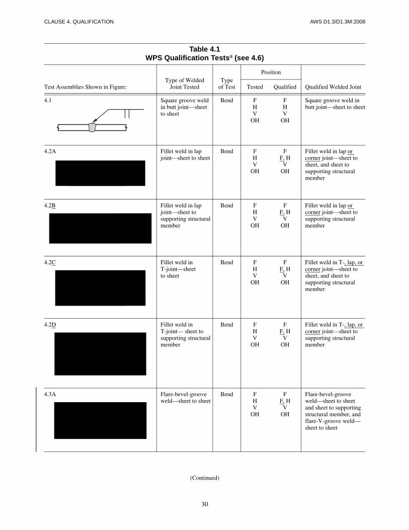
30
CLAUSE 4. QUALIFICATION AWS D1.3/D1.3M:2008
Table 4.1WPS Qualification Testsa (see 4.6)
Test Assemblies Shown in Figure:Type of Welded
Joint TestedType
of Test
Position
Qualified Welded JointTested Qualified
4.1 Square groove weldin butt joint—sheet to sheet
Bend FHV
OH
FHV
OH
Square groove weld in butt joint—sheet to sheet
4.2A Fillet weld in lap joint—sheet to sheet
Bend FHV
OH
FF, H
VOH
Fillet weld in lap or corner joint—sheet to sheet, and sheet to supporting structural member
4.2B Fillet weld in lap joint—sheet to supporting structural member
Bend FHV
OH
FF, H
VOH
Fillet weld in lap or corner joint—sheet to supporting structural member
4.2C Fillet weld inT-joint—sheet to sheet
Bend FHV
OH
FF, H
VOH
Fillet weld in T-, lap, or corner joint—sheet to sheet, and sheet to supporting structural member
4.2D Fillet weld inT-joint— sheet to supporting structural member
Bend FHV
OH
FF, H
VOH
Fillet weld in T-, lap, or corner joint—sheet to supporting structural member
4.3A Flare-bevel-groove weld—sheet to sheet
Bend FHV
OH
FF, H
VOH
Flare-bevel-groove weld—sheet to sheet and sheet to supporting structural member, and flare-V-groove weld—sheet to sheet
(Continued)

31
AWS D1.3/D1.3M:2008 CLAUSE 4. QUALIFICATION
4.3B Flare-bevel-groove weld—sheet to supporting structural member
Bend FHV
OH
FF, H
VOH
Flare-bevel-groove weld—sheet to supporting structural member
4.3C Flare-V-groove weld—sheet to sheet
Bend FHV
OH
FHV
OH
Flare-V-groove weld—sheet to sheet and flare-bevel-groove weld—sheet to sheet and sheet to supporting structural member
4.4 Arc spot weld—sheet to supporting structural member
Torsion F F Arc spot and arc seam weld—sheet to supporting structural member
4.5A Arc seam weld—sheet to supporting structural member
Bend F F Arc seam weld—sheet to supporting structural member
4.5B Arc seam weld—sheet to sheet
Bend H H Arc seam weld—sheet to sheet
4.6 Arc plug weld—sheet to supporting structural member
Torsion FHV
OH
FHV
OH
Arc plug weld—sheet to sheet, and sheet to supporting structural member
a Two tests shall be required for each welding position, thickness, and type of coating (see 4.5 for essential variable limitations).
Table 4.1 (Continued)WPS Qualification Testsa (see 4.6)
Test Assemblies Shown in Figure:Type of Welded
Joint TestedType
of Test
Position
Qualified Welded JointTested Qualified
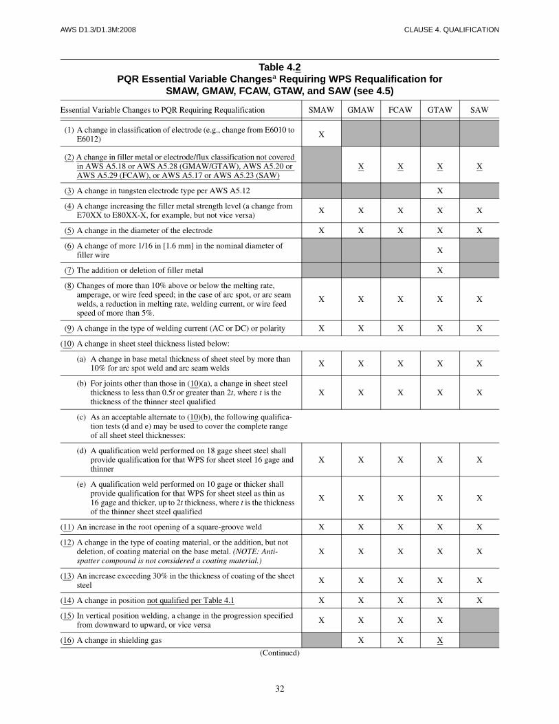
32
AWS D1.3/D1.3M:2008 CLAUSE 4. QUALIFICATION
Table 4.2PQR Essential Variable Changesa Requiring WPS Requalification for
SMAW, GMAW, FCAW, GTAW, and SAW (see 4.5)
Essential Variable Changes to PQR Requiring Requalification SMAW GMAW FCAW GTAW SAW
(1) A change in classification of electrode (e.g., change from E6010 to E6012) X
(2) A change in filler metal or electrode/flux classification not covered in AWS A5.18 or AWS A5.28 (GMAW/GTAW), AWS A5.20 or AWS A5.29 (FCAW), or AWS A5.17 or AWS A5.23 (SAW)
X X X X
(3) A change in tungsten electrode type per AWS A5.12 X
(4) A change increasing the filler metal strength level (a change from E70XX to E80XX-X, for example, but not vice versa) X X X X X
(5) A change in the diameter of the electrode X X X X X
(6) A change of more 1/16 in [1.6 mm] in the nominal diameter of filler wire X
(7) The addition or deletion of filler metal X
(8) Changes of more than 10% above or below the melting rate, amperage, or wire feed speed; in the case of arc spot, or arc seam welds, a reduction in melting rate, welding current, or wire feed speed of more than 5%.
X X X X X
(9) A change in the type of welding current (AC or DC) or polarity X X X X X
(10) A change in sheet steel thickness listed below:
(a) A change in base metal thickness of sheet steel by more than 10% for arc spot weld and arc seam welds X X X X X
(b) For joints other than those in (10)(a), a change in sheet steel thickness to less than 0.5t or greater than 2t, where t is the thickness of the thinner steel qualified
X X X X X
(c) As an acceptable alternate to (10)(b), the following qualifica-tion tests (d and e) may be used to cover the complete range of all sheet steel thicknesses:
(d) A qualification weld performed on 18 gage sheet steel shall provide qualification for that WPS for sheet steel 16 gage and thinner
X X X X X
(e) A qualification weld performed on 10 gage or thicker shall provide qualification for that WPS for sheet steel as thin as 16 gage and thicker, up to 2t thickness, where t is the thickness of the thinner sheet steel qualified
X X X X X
(11) An increase in the root opening of a square-groove weld X X X X X
(12) A change in the type of coating material, or the addition, but not deletion, of coating material on the base metal. (NOTE: Anti-spatter compound is not considered a coating material.)
X X X X X
(13) An increase exceeding 30% in the thickness of coating of the sheet steel X X X X X
(14) A change in position not qualified per Table 4.1 X X X X X
(15) In vertical position welding, a change in the progression specified from downward to upward, or vice versa X X X X
(16) A change in shielding gas X X X
(Continued)

33
AWS D1.3/D1.3M:2008 CLAUSE 4. QUALIFICATION
(17) The deletion, but not the addition, of backing gas X X X
(18) The deletion, but not the addition, of permanent or removable backing X X X X X
(19) A change in AWS flux/electrode classification X
(20) A change in more than 10% above or below the specified mean PQR arc voltage for each electrode diameter used X X X
(21) An increase of 25% or more or a decrease of 10% or more in the rate of flow or shielding gas or mixture X X X
(22) A change in the mode of metal transfer across the arc X
(23) A change from cold wire feed to hot wire feed or vice versa X
(24) For square groove welds in butt joints, a change in welding from both sides to welding from one side, but not vice versa X X X X X
(25) For arc spot and arc seam welds, a decrease in weld design of size d X X X X X
(26) For arc spot welds, a decrease in weld time. X X X X X
(27) For arc seam welds, an increase in travel speed X X X X X
a An “X” indicates applicability for the process: a shaded area indicates nonapplicability.
Table 4.3Electrode Classification Groups
Group Designation AWS Electrode Classification
F4F3F2
EXX15, EXX16, EXX18, EXX15-X, EXX16-X, EXX18-XEXX10, EXX11, EXX10-X, EXX11-XEXX12, EXX13, EXX14, EXX13-X
Note: The letters XX, used in the classification designation in this table, stand for the various strength levels, (e.g., 60, 70, etc.) of electrodes.
Table 4.2 (Continued)PQR Essential Variable Changesa Requiring WPS Requalification for
SMAW, GMAW, FCAW, GTAW, and SAW (see 4.5)
Essential Variable Changes to PQR Requiring Requalification SMAW GMAW FCAW GTAW SAW

34
CLAUSE 4. QUALIFICATION AWS D1.3/D1.3M:2008
Table 4.4Welder Performance Qualification Testsa (see 4.8)
Test Assemblies Shown in Figure:Type of Welded
Joint TestedType
of Test
Position Qualified
Tested Qualified Welded Joint Thickness
4.1 Square-groove weld in butt joint—sheet to sheet
Bend FHV
OH
FF, H
F, H, VF, H, OH
Square-groove weld in butt joint—sheet to sheet
Thickness tested [except as modified by 4.7.2(3)]
4.2A Fillet weld in lap joint—sheet to sheet
Bend FHV
OH
FF, H
F, H, VF, H, OH
Fillet weld in lapor corner joint—sheet to sheet, and sheet to supporting structural member
Thickness tested and thicker
4.2B Fillet weld in lap joint—sheet to supporting structuralmember
Bend FHV
OH
FF, H
F, H, VF, H, OH
Fillet weld in lapor corner joint—sheet to supporting structural member
Thickness tested and thicker
4.2C Fillet weld inT-joint—sheetto sheet
Bend FHV
OH
FF, H
F, H, VF, H, OH
Fillet weld in T-,lap, or cornerjoint—sheet tosheet, and sheetto supporting structural member
Thickness tested and thicker
4.2D Fillet weldedT-joint, sheetto supportingmember
Bend FHV
OH
FF, H
F, H, VF, H, OH
Fillet welded T-,lap, or corner joint,sheet to supportingmember
Thicknesstested andthicker
4.3A Flare-bevel-groove weld—sheet to sheet
Bend FHV
OH
FF, H
F, H, VF, H, OH
Flare-bevel-groove weld—sheet to sheet and sheet to supporting structural member, and flare-V-groove weld—sheet to sheet
Thickness tested and thicker
4.3B Flare-bevel-groove weld—sheet to supportingstructuralmember
Bend FHV
OH
FF, H
F, H, VF, H, OH
Flare-bevel-groove weld—sheet to supporting structural member
Thickness tested and thicker
(Continued)
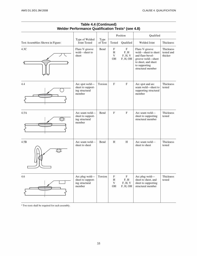
35
AWS D1.3/D1.3M:2008 CLAUSE 4. QUALIFICATION
4.3C Flare-V-groove weld—sheet to sheet
Bend FHV
OH
FF, H
F, H, VF, H, OH
Flare-V-groove weld—sheet to sheet and flare-bevel-groove weld—sheet to sheet, and sheet to supporting structural member
Thickness tested and thicker
4.4 Arc spot weld—sheet to support-ing structural member
Torsion F F Arc spot and arc seam weld—sheet to supporting structural member
Thickness tested
4.5A Arc seam weld—sheet to support-ing structural member
Bend F F Arc seam weld—sheet to supporting structural member
Thickness tested
4.5B Arc seam weld—sheet to sheet
Bend H H Arc seam weld—sheet to sheet
Thickness tested
4.6 Arc plug weld—sheet to support-ing structural member
Torsion FHV
OH
FF, H
F, H, VF, H, OH
Arc plug weld—sheet to sheet, and sheet to supporting structural member
Thickness tested
a Two tests shall be required for each assembly.
Table 4.4 (Continued)Welder Performance Qualification Testsa (see 4.8)
Test Assemblies Shown in Figure:Type of Welded
Joint TestedType
of Test
Position Qualified
Tested Qualified Welded Joint Thickness
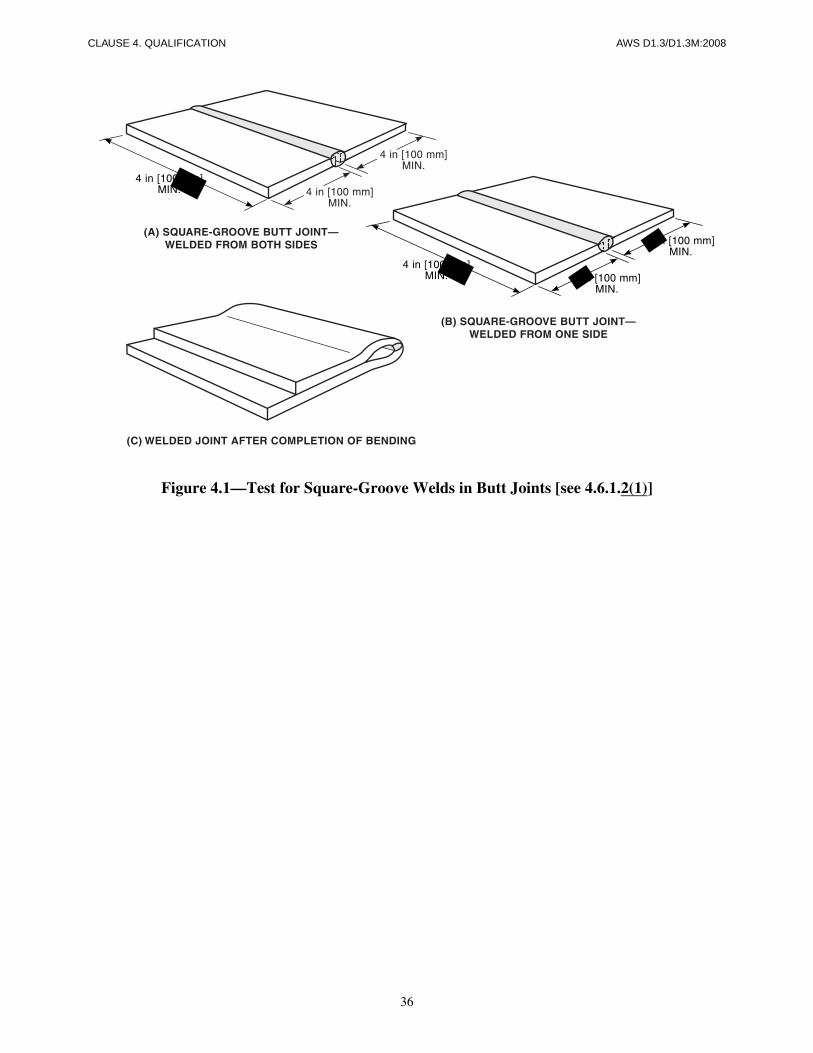
36
CLAUSE 4. QUALIFICATION AWS D1.3/D1.3M:2008
Figure 4.1—Test for Square-Groove Welds in Butt Joints [see 4.6.1.2(1)]
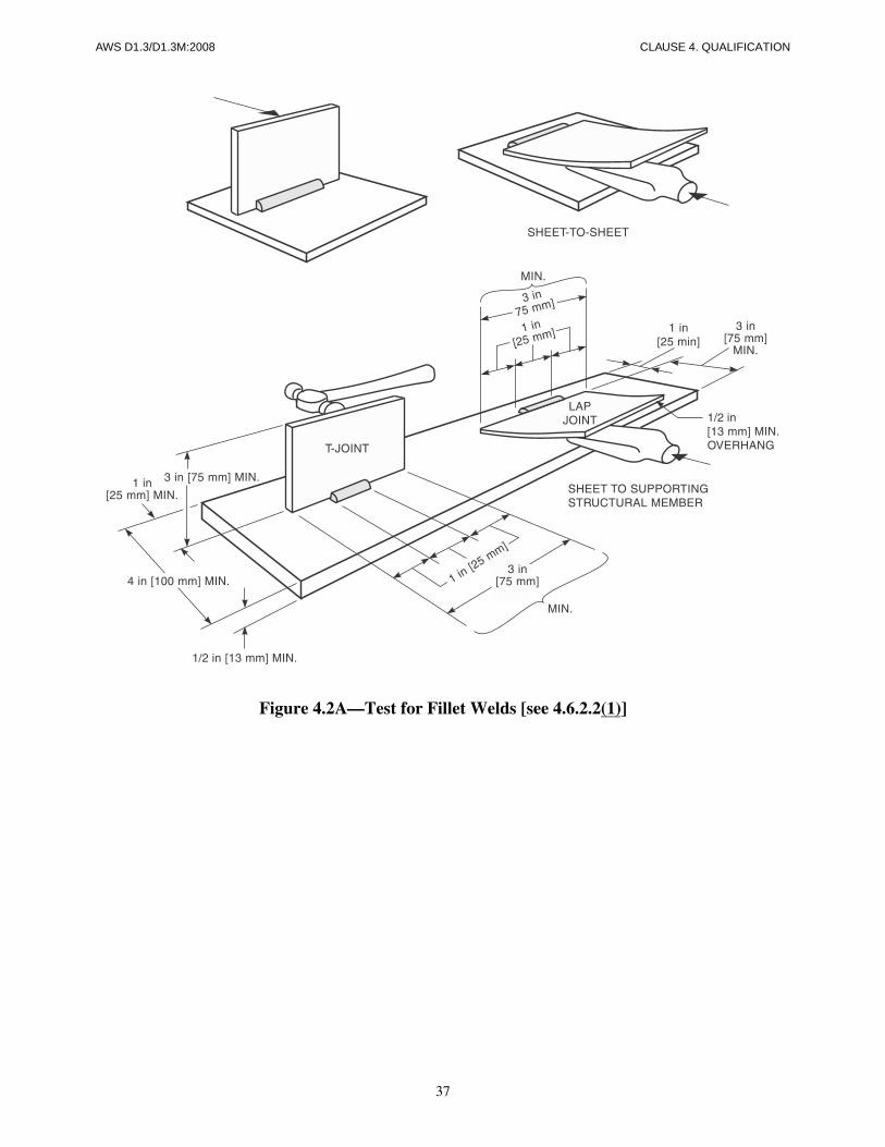
37
AWS D1.3/D1.3M:2008 CLAUSE 4. QUALIFICATION
Figure 4.2A—Test for Fillet Welds [see 4.6.2.2(1)]
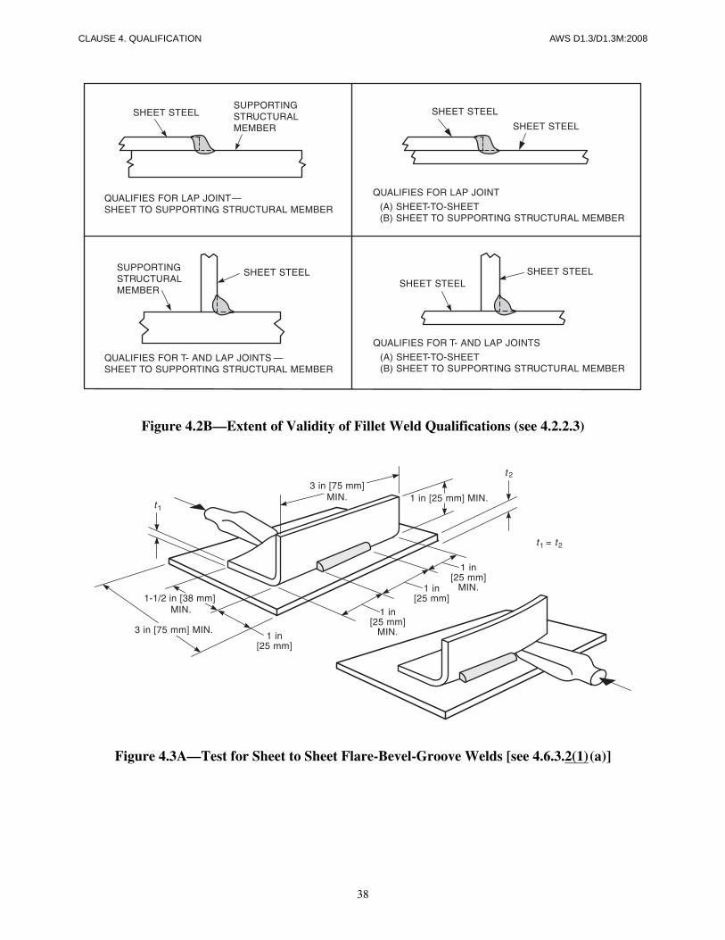
38
CLAUSE 4. QUALIFICATION AWS D1.3/D1.3M:2008
Figure 4.2B—Extent of Validity of Fillet Weld Qualifications (see 4.2.2.3)
Figure 4.3A—Test for Sheet to Sheet Flare-Bevel-Groove Welds [see 4.6.3.2(1)(a)]
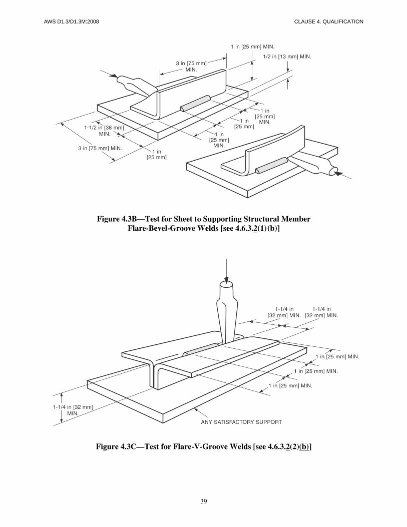
39
AWS D1.3/D1.3M:2008 CLAUSE 4. QUALIFICATION
Figure 4.3B—Test for Sheet to Supporting Structural MemberFlare-Bevel-Groove Welds [see 4.6.3.2(1)(b)]
Figure 4.3C—Test for Flare-V-Groove Welds [see 4.6.3.2(2)(b)]
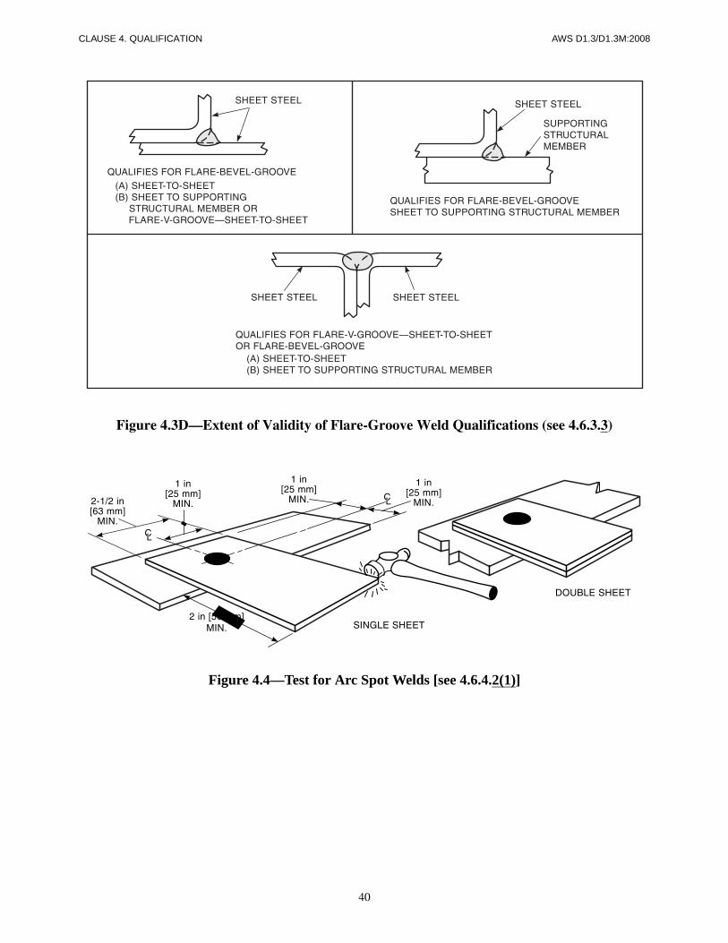
40
CLAUSE 4. QUALIFICATION AWS D1.3/D1.3M:2008
Figure 4.3D—Extent of Validity of Flare-Groove Weld Qualifications (see 4.6.3.3)
Figure 4.4—Test for Arc Spot Welds [see 4.6.4.2(1)]
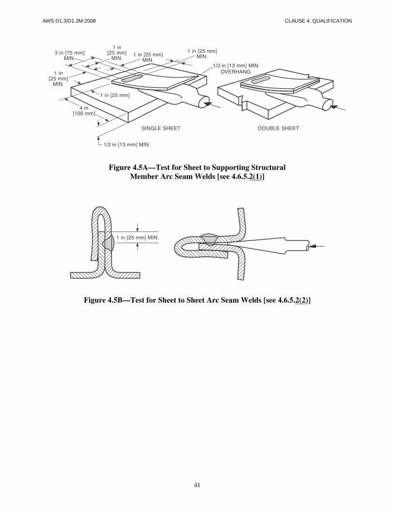
41
AWS D1.3/D1.3M:2008 CLAUSE 4. QUALIFICATION
Figure 4.5A—Test for Sheet to Supporting StructuralMember Arc Seam Welds [see 4.6.5.2(1)]
Figure 4.5B—Test for Sheet to Sheet Arc Seam Welds [see 4.6.5.2(2)]

42
CLAUSE 4. QUALIFICATION AWS D1.3/D1.3M:2008
Typical for multi-ply sheet to supporting structural member or sheet-to-sheet—also used for horizontal, vertical, and overhead positions.
Figure 4.6—Test for Arc Plug Welds [see 4.6.6.2(1)]

43
AWS D1.3/D1.3M:2008 CLAUSE 4. QUALIFICATION
Figure 4.6 (Continued)—Test for Arc Plug Welds [see 4.6.2.2(1)]

This page is intentionally blank.
44
AWS D1.3/D1.3M:2008
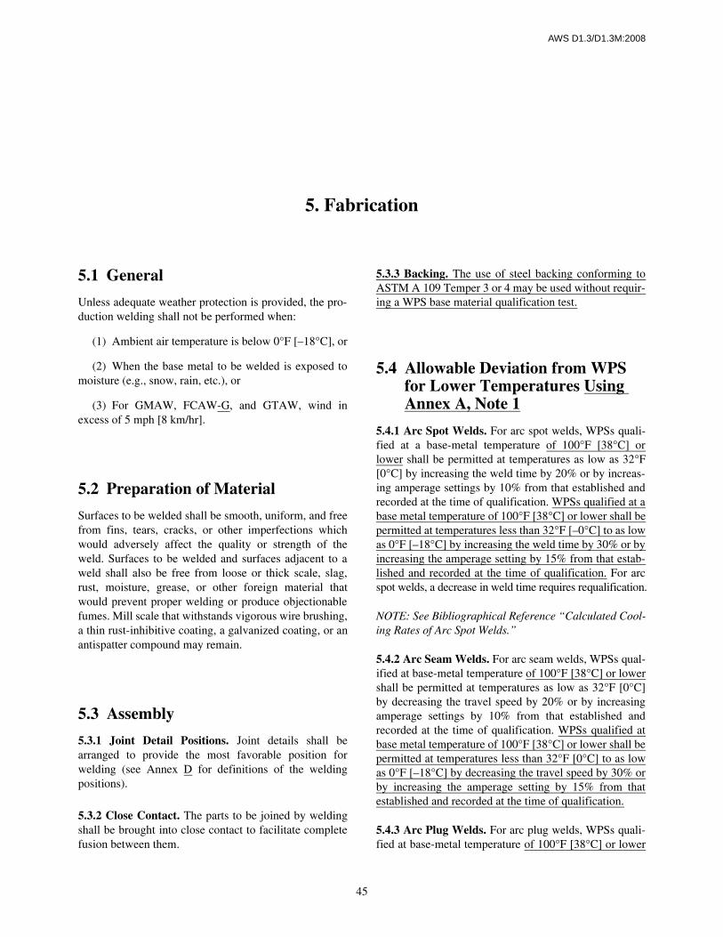
AWS D1.3/D1.3M:2008
45
5.1 General
Unless adequate weather protection is provided, the pro-duction welding shall not be performed when:
(1) Ambient air temperature is below 0°F [–18°C], or
(2) When the base metal to be welded is exposed tomoisture (e.g., snow, rain, etc.), or
(3) For GMAW, FCAW-G, and GTAW, wind inexcess of 5 mph [8 km/hr].
5.2 Preparation of Material
Surfaces to be welded shall be smooth, uniform, and freefrom fins, tears, cracks, or other imperfections whichwould adversely affect the quality or strength of theweld. Surfaces to be welded and surfaces adjacent to aweld shall also be free from loose or thick scale, slag,rust, moisture, grease, or other foreign material thatwould prevent proper welding or produce objectionablefumes. Mill scale that withstands vigorous wire brushing,a thin rust-inhibitive coating, a galvanized coating, or anantispatter compound may remain.
5.3 Assembly
5.3.1 Joint Detail Positions. Joint details shall bearranged to provide the most favorable position forwelding (see Annex D for definitions of the weldingpositions).
5.3.2 Close Contact. The parts to be joined by weldingshall be brought into close contact to facilitate completefusion between them.
5.3.3 Backing. The use of steel backing conforming toASTM A 109 Temper 3 or 4 may be used without requir-ing a WPS base material qualification test.
5.4 Allowable Deviation from WPS for Lower Temperatures Using Annex A, Note 1
5.4.1 Arc Spot Welds. For arc spot welds, WPSs quali-fied at a base-metal temperature of 100°F [38°C] orlower shall be permitted at temperatures as low as 32°F[0°C] by increasing the weld time by 20% or by increas-ing amperage settings by 10% from that established andrecorded at the time of qualification. WPSs qualified at abase metal temperature of 100°F [38°C] or lower shall bepermitted at temperatures less than 32°F [–0°C] to as lowas 0°F [–18°C] by increasing the weld time by 30% or byincreasing the amperage setting by 15% from that estab-lished and recorded at the time of qualification. For arcspot welds, a decrease in weld time requires requalification.
NOTE: See Bibliographical Reference “Calculated Cool-ing Rates of Arc Spot Welds.”
5.4.2 Arc Seam Welds. For arc seam welds, WPSs qual-ified at base-metal temperature of 100°F [38°C] or lowershall be permitted at temperatures as low as 32°F [0°C]by decreasing the travel speed by 20% or by increasingamperage settings by 10% from that established andrecorded at the time of qualification. WPSs qualified atbase metal temperature of 100°F [38°C] or lower shall bepermitted at temperatures less than 32°F [0°C] to as lowas 0°F [–18°C] by decreasing the travel speed by 30% orby increasing the amperage setting by 15% from thatestablished and recorded at the time of qualification.
5.4.3 Arc Plug Welds. For arc plug welds, WPSs quali-fied at base-metal temperature of 100°F [38°C] or lower
5. Fabrication
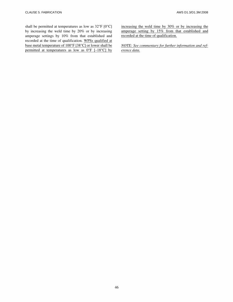
CLAUSE 5. FABRICATION AWS D1.3/D1.3M:2008
46
shall be permitted at temperatures as low as 32°F [0°C]by increasing the weld time by 20% or by increasingamperage settings by 10% from that established andrecorded at the time of qualification. WPSs qualified atbase metal temperature of 100°F [38°C] or lower shall bepermitted at temperatures as low as 0°F [–18°C] by
increasing the weld time by 30% or by increasing theamperage setting by 15% from that established andrecorded at the time of qualification.
NOTE: See commentary for further information and ref-erence data.

AWS D1.3/D1.3M:2008
47
Part AAcceptance Criteria
6.1 Production Weld Acceptance Criteria
6.1.1 Visual Inspection. A weld shall be acceptable byvisual inspection, provided the following criteria are met:
6.1.1.1 No Cracks. The weld shall have no cracks.
6.1.1.2 Weld/Base-Metal Fusion. There shall be noevidence of lack of fusion at the toes of weld passes.
6.1.1.3 Minimum Reinforcement. The weld shallhave minimum reinforcement of 1/32 in [1 mm] for allsquare groove, arc spot, and arc seam welds.
6.1.1.4 Undercut. The cumulative length of undercutshall be no longer than L/8, where L is the specifiedlength of the weld or in the case of arc spot welds, thecircumference, provided fusion exists between the weldmetal and the base metal. Depth of undercut is not a sub-ject of inspection and need not be measured. Melt-through that results in a hole is unacceptable.
6.1.1.5 Fillet Weld Face. Faces of fillet welds shallbe flat or slightly convex.
6.1.1.6 Contract Document Conformance. Loca-tion, size, and length of weld shall be in conformancewith drawings or other contract document requirements.
Part BContractor’s Responsibility
6.2 Inspection of WPS and Welder Qualifications
6.2.1 The Inspector shall ascertain that in performingwork to this code, only qualified or prequalified WPSsare used, and all welders are qualified.
6.2.2 WPSs previously qualified or prequalified by themanufacturer or contractor may be used, if approved bythe Engineer. However, if the Engineer does not acceptsuch evidence, the contractor shall qualify the WPSs inconformance with this code. The contractor’s weld testsshall be successfully completed before any permanentwelding is done on the contract.
6.3 Inspection of Work6.3.1 Requests. At any time, and specifically while arcspot welds or arc seam welds are being made, the Inspec-tor may request that the melting rate of the electrodes,wire feed speed, or welding current be compared withthat established in the WPS qualification test. If thesemelting rates are 5% or more below those specified, newwelds using the correct current shall be made adjacent tothose welds made with the inadequate current.
6.3.2 Work Quality. When the quality of a welder’swork is judged by the Inspector to be below the require-ments of this specification, requalification of the weldermay be required.
6. Inspection

This page is intentionally blank.
48
AWS D1.3/D1.3M:2008
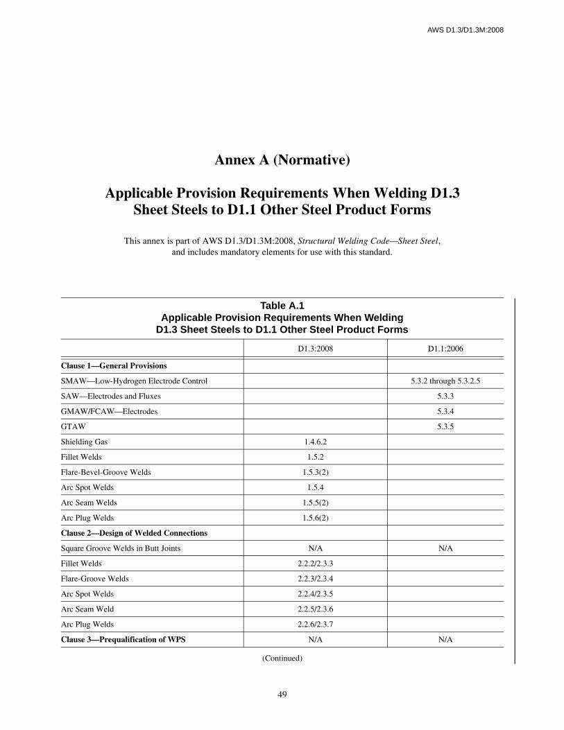
AWS D1.3/D1.3M:2008
49
Table A.1Applicable Provision Requirements When Welding
D1.3 Sheet Steels to D1.1 Other Steel Product Forms
D1.3:2008 D1.1:2006
Clause 1—General Provisions
SMAW—Low-Hydrogen Electrode Control 5.3.2 through 5.3.2.5
SAW—Electrodes and Fluxes 5.3.3
GMAW/FCAW—Electrodes 5.3.4
GTAW 5.3.5
Shielding Gas 1.4.6.2
Fillet Welds 1.5.2
Flare-Bevel-Groove Welds 1.5.3(2)
Arc Spot Welds 1.5.4
Arc Seam Welds 1.5.5(2)
Arc Plug Welds 1.5.6(2)
Clause 2—Design of Welded Connections
Square Groove Welds in Butt Joints N/A N/A
Fillet Welds 2.2.2/2.3.3
Flare-Groove Welds 2.2.3/2.3.4
Arc Spot Welds 2.2.4/2.3.5
Arc Seam Weld 2.2.5/2.3.6
Arc Plug Welds 2.2.6/2.3.7
Clause 3—Prequalification of WPS N/A N/A
Annex A (Normative)
Applicable Provision Requirements When Welding D1.3Sheet Steels to D1.1 Other Steel Product Forms
This annex is part of AWS D1.3/D1.3M:2008, Structural Welding Code—Sheet Steel,and includes mandatory elements for use with this standard.
(Continued)
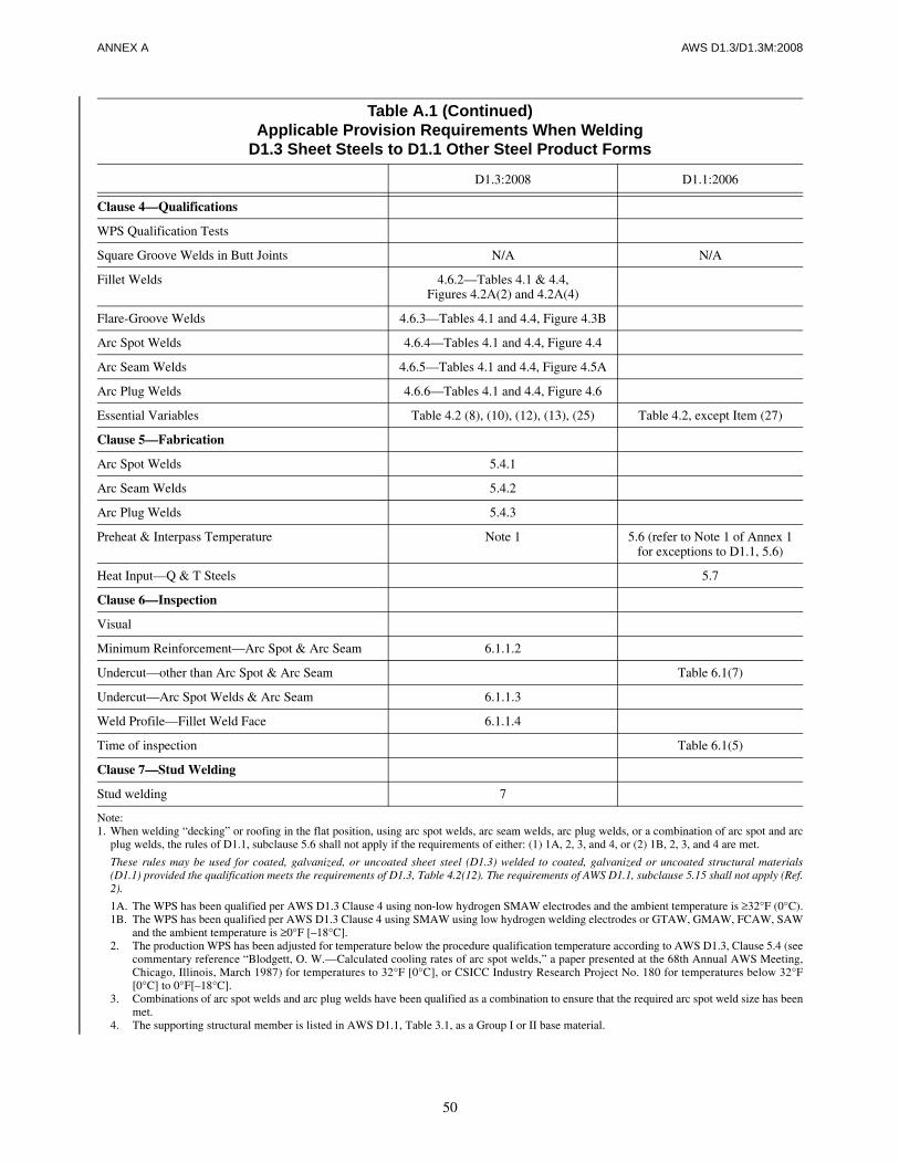
50
ANNEX A AWS D1.3/D1.3M:2008
Clause 4—Qualifications
WPS Qualification Tests
Square Groove Welds in Butt Joints N/A N/A
Fillet Welds 4.6.2—Tables 4.1 & 4.4,Figures 4.2A(2) and 4.2A(4)
Flare-Groove Welds 4.6.3—Tables 4.1 and 4.4, Figure 4.3B
Arc Spot Welds 4.6.4—Tables 4.1 and 4.4, Figure 4.4
Arc Seam Welds 4.6.5—Tables 4.1 and 4.4, Figure 4.5A
Arc Plug Welds 4.6.6—Tables 4.1 and 4.4, Figure 4.6
Essential Variables Table 4.2 (8), (10), (12), (13), (25) Table 4.2, except Item (27)
Clause 5—Fabrication
Arc Spot Welds 5.4.1
Arc Seam Welds 5.4.2
Arc Plug Welds 5.4.3
Preheat & Interpass Temperature Note 1 5.6 (refer to Note 1 of Annex 1for exceptions to D1.1, 5.6)
Heat Input—Q & T Steels 5.7
Clause 6—Inspection
Visual
Minimum Reinforcement—Arc Spot & Arc Seam 6.1.1.2
Undercut—other than Arc Spot & Arc Seam Table 6.1(7)
Undercut—Arc Spot Welds & Arc Seam 6.1.1.3
Weld Profile—Fillet Weld Face 6.1.1.4
Time of inspection Table 6.1(5)
Clause 7—Stud Welding
Stud welding 7
Note:1. When welding “decking” or roofing in the flat position, using arc spot welds, arc seam welds, arc plug welds, or a combination of arc spot and arc
plug welds, the rules of D1.1, subclause 5.6 shall not apply if the requirements of either: (1) 1A, 2, 3, and 4, or (2) 1B, 2, 3, and 4 are met.
These rules may be used for coated, galvanized, or uncoated sheet steel (D1.3) welded to coated, galvanized or uncoated structural materials(D1.1) provided the qualification meets the requirements of D1.3, Table 4.2(12). The requirements of AWS D1.1, subclause 5.15 shall not apply (Ref.2).
1A. The WPS has been qualified per AWS D1.3 Clause 4 using non-low hydrogen SMAW electrodes and the ambient temperature is ≥32°F (0°C).1B. The WPS has been qualified per AWS D1.3 Clause 4 using SMAW using low hydrogen welding electrodes or GTAW, GMAW, FCAW, SAW
and the ambient temperature is ≥0°F [–18°C].2. The production WPS has been adjusted for temperature below the procedure qualification temperature according to AWS D1.3, Clause 5.4 (see
commentary reference “Blodgett, O. W.—Calculated cooling rates of arc spot welds,” a paper presented at the 68th Annual AWS Meeting,Chicago, Illinois, March 1987) for temperatures to 32°F [0°C], or CSICC Industry Research Project No. 180 for temperatures below 32°F[0°C] to 0°F[–18°C].
3. Combinations of arc spot welds and arc plug welds have been qualified as a combination to ensure that the required arc spot weld size has beenmet.
4. The supporting structural member is listed in AWS D1.1, Table 3.1, as a Group I or II base material.
Table A.1 (Continued)Applicable Provision Requirements When Welding
D1.3 Sheet Steels to D1.1 Other Steel Product Forms
D1.3:2008 D1.1:2006
AWS D1.3/D1.3M:2007
51
This annex contains three forms that the AWS D1 Committee on Structural Welding has approved for the recording ofthe welding procedure qualification test record (PQR), welding procedure specification, and welder or welding operatorqualification test record data required by this code.
It is suggested that the qualification information required by this code be recorded on these forms or similar forms whichhave been prepared by the user. Variations of these forms to suit the user’s needs are permissible.
Annex B (Informative)
Sample Welding Forms
This annex is not part of AWS D1.3/D1.3M:2008, Structural Welding Code—Sheet Steel, but is included for informational purposes only.
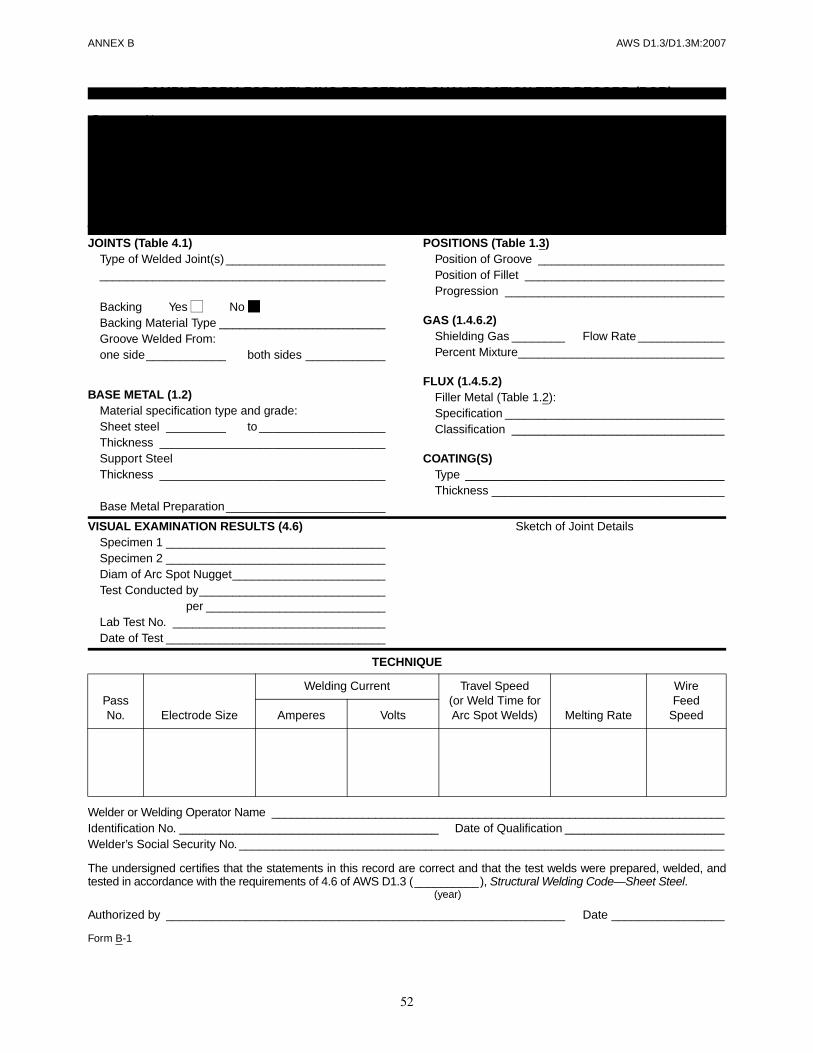
52
ANNEX B AWS D1.3/D1.3M:2007
VISUAL EXAMINATION RESULTS (4.6) Sketch of Joint DetailsSpecimen 1 _________________________________Specimen 2 _________________________________Diam of Arc Spot Nugget_______________________Test Conducted by____________________________Test Conducted per ___________________________Lab Test No. ________________________________Date of Test _________________________________
TECHNIQUE
Welder or Welding Operator Name ______________________________________________________________________Identification No. _______________________________________ Date of Qualification ________________________Welder’s Social Security No. _________________________________________________________________________
The undersigned certifies that the statements in this record are correct and that the test welds were prepared, welded, andtested in accordance with the requirements of 4.6 of AWS D1.3 (__________), Structural Welding Code—Sheet Steel.
(year)
Authorized by ____________________________________________________________ Date _________________
Form B-1
PassNo. Electrode Size
Welding Current Travel Speed(or Weld Time for Arc Spot Welds) Melting Rate
WireFeed
SpeedAmperes Volts
JOINTS (Table 4.1)Type of Welded Joint(s) ___________________________________________________________________
Backing Yes No Backing Material Type _________________________Groove Welded From:one side____________ both sides ____________
BASE METAL (1.2)Material specification type and grade:Sheet steel _________ to ___________________Thickness __________________________________Support SteelThickness __________________________________
Base Metal Preparation________________________
POSITIONS (Table 1.3)Position of Groove ____________________________Position of Fillet ______________________________Progression _________________________________
GAS (1.4.6.2)Shielding Gas ________ Flow Rate _____________Percent Mixture_______________________________
FLUX (1.4.5.2)Filler Metal (Table 1.2):Specification _________________________________Classification ________________________________
COATING(S)Type _______________________________________Thickness ___________________________________
SAMPLE FORM FOR WELDING PROCEDURE QUALIFICATION TEST RECORD (PQR)
Company Name __________________________________________________________________________________Procedure Qualification Test Record No. ____________________________________ Date ___________________Welding Procedure Specification No._______________________ Rev __________ Date ___________________Welding Process(es) ___________________________________ Type ____________________________________
(Automatic, manual, etc.)Mode of Transfer for GMAW_________________________________________________________________________
(Short circuiting, spray, etc.)
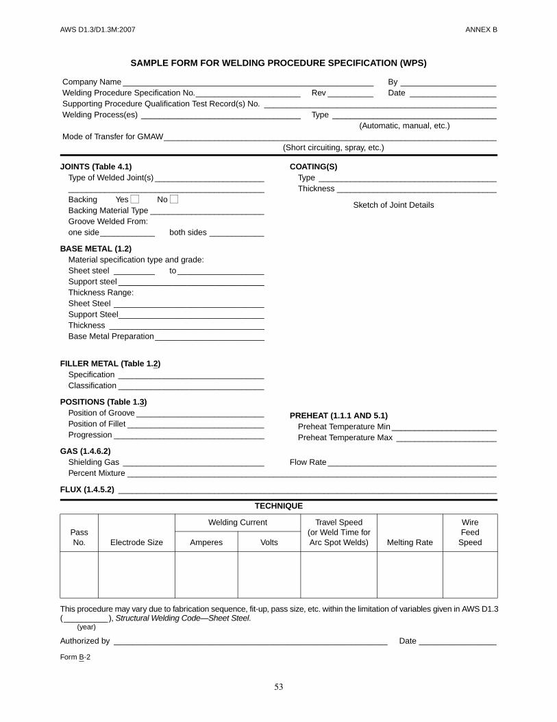
53
AWS D1.3/D1.3M:2007 ANNEX B
GAS (1.4.6.2)Shielding Gas _______________________________ Flow Rate _____________________________________Percent Mixture _________________________________________________________________________________
FLUX (1.4.5.2) ___________________________________________________________________________________
TECHNIQUE
This procedure may vary due to fabrication sequence, fit-up, pass size, etc. within the limitation of variables given in AWS D1.3( __________ ), Structural Welding Code—Sheet Steel.
(year)
Authorized by ____________________________________________________________ Date _________________
Form B-2
PassNo. Electrode Size
Welding Current Travel Speed(or Weld Time for Arc Spot Welds) Melting Rate
WireFeed
SpeedAmperes Volts
JOINTS (Table 4.1)Type of Welded Joint(s) ___________________________________________________________________Backing Yes No Backing Material Type _________________________Groove Welded From:one side____________ both sides ____________
BASE METAL (1.2)Material specification type and grade:Sheet steel _________ to ___________________Support steel ________________________________Thickness Range:Sheet Steel _________________________________Support Steel________________________________Thickness __________________________________Base Metal Preparation ________________________
FILLER METAL (Table 1.2)Specification ________________________________Classification ________________________________
POSITIONS (Table 1.3)Position of Groove ____________________________Position of Fillet ______________________________Progression _________________________________
COATING(S)Type _______________________________________Thickness ___________________________________
Sketch of Joint Details
SAMPLE FORM FOR WELDING PROCEDURE SPECIFICATION (WPS)
Company Name _______________________________________________________ By _____________________Welding Procedure Specification No._______________________ Rev __________ Date ___________________Supporting Procedure Qualification Test Record(s) No. ___________________________________________________Welding Process(es) ___________________________________ Type ____________________________________
(Automatic, manual, etc.)Mode of Transfer for GMAW_________________________________________________________________________
(Short circuiting, spray, etc.)
PREHEAT (1.1.1 AND 5.1)Preheat Temperature Min _______________________Preheat Temperature Max ______________________
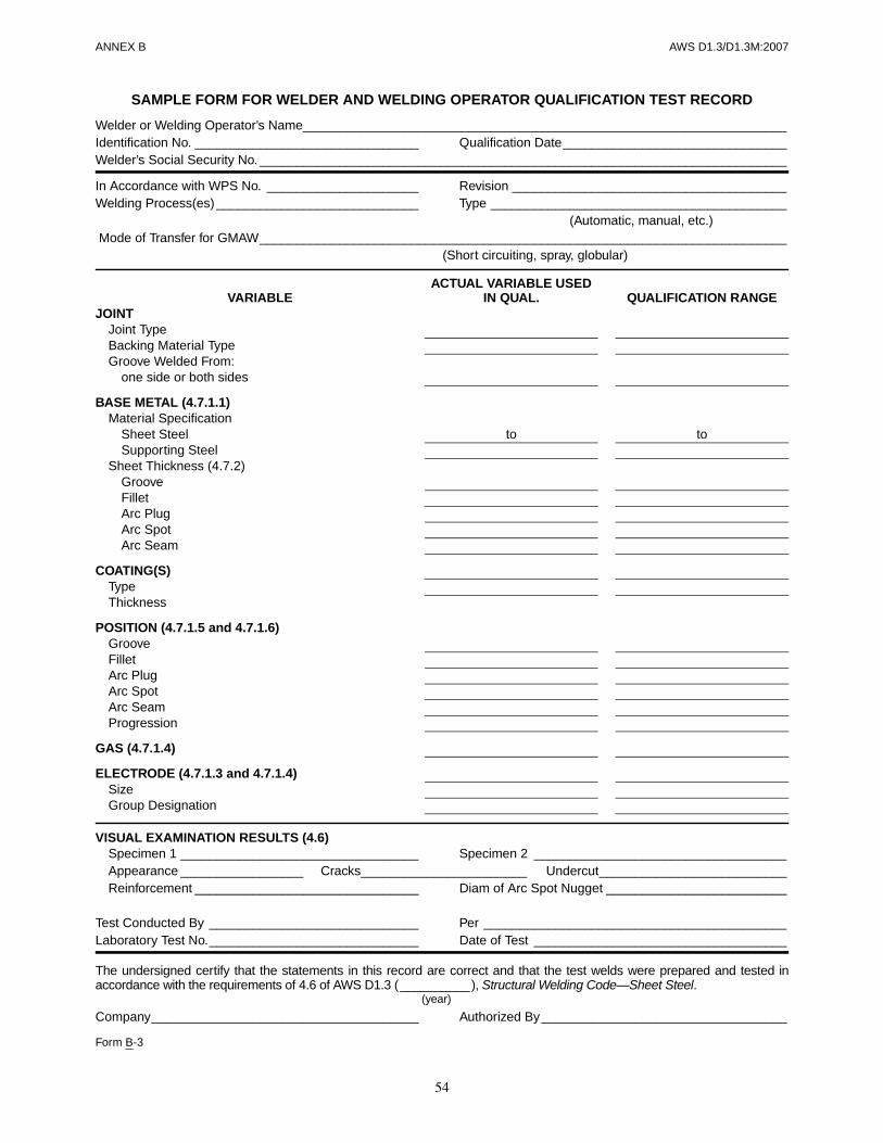
54
ANNEX B AWS D1.3/D1.3M:2007
SAMPLE FORM FOR WELDER AND WELDING OPERATOR QUALIFICATION TEST RECORD
Welder or Welding Operator’s Name___________________________________________________________________Identification No. _______________________________ Qualification Date_______________________________Welder’s Social Security No. _________________________________________________________________________
In Accordance with WPS No. _____________________ Revision ______________________________________Welding Process(es) ____________________________ Type _________________________________________
(Automatic, manual, etc.)Mode of Transfer for GMAW_________________________________________________________________________
(Short circuiting, spray, globular)
VISUAL EXAMINATION RESULTS (4.6)Specimen 1 _________________________________ Specimen 2 ___________________________________Appearance _________________ Cracks_______________________ Undercut__________________________Reinforcement _______________________________ Diam of Arc Spot Nugget _________________________
Test Conducted By _____________________________ Per __________________________________________Laboratory Test No._____________________________ Date of Test ___________________________________
The undersigned certify that the statements in this record are correct and that the test welds were prepared and tested inaccordance with the requirements of 4.6 of AWS D1.3 (__________), Structural Welding Code—Sheet Steel.
(year)
Company_____________________________________ Authorized By__________________________________
Form B-3
VARIABLEACTUAL VARIABLE USED
IN QUAL. QUALIFICATION RANGEJOINT
Joint TypeBacking Material TypeGroove Welded From:
one side or both sides
BASE METAL (4.7.1.1)Material Specification
Sheet Steel to toSupporting Steel
Sheet Thickness (4.7.2)GrooveFilletArc PlugArc SpotArc Seam
COATING(S)TypeThickness
POSITION (4.7.1.5 and 4.7.1.6)GrooveFilletArc PlugArc SpotArc SeamProgression
GAS (4.7.1.4)
ELECTRODE (4.7.1.3 and 4.7.1.4)SizeGroup Designation

AWS D1.3/D1.3M:2007
55
C1. IntroductionThe American Welding Society (AWS) Board of Directorshas adopted a policy whereby all official interpretationsof AWS standards are handled in a formal manner.Under this policy, all interpretations are made by thecommittee that is responsible for the standard. Officialcommunication concerning an interpretation is directedthrough the AWS staff member who works with thatcommittee. The policy requires that all requests for aninterpretation be submitted in writing. Such requests willbe handled as expeditiously as possible, but due to thecomplexity of the work and the procedures that must befollowed, some interpretations may require considerabletime.
C2. ProcedureAll inquiries shall be directed to:
Managing DirectorTechnical Services DivisionAmerican Welding Society550 N.W. LeJeune RoadMiami, FL 33126
All inquiries shall contain the name, address, andaffiliation of the inquirer, and they shall provide enoughinformation for the committee to understand the point ofconcern in the inquiry. When the point is not clearlydefined, the inquiry will be returned for clarification. Forefficient handling, all inquiries should be typewritten andin the format specified below.
C2.1 Scope. Each inquiry shall address one single provi-sion of the code, unless the point of the inquiry involvestwo or more interrelated provisions. The provision(s)shall be identified in the scope of the inquiry along withthe edition of the code that contains the provision(s) theinquirer is addressing.
C2.2 Purpose of the Inquiry. The purpose of the inquiryshall be stated in this portion of the inquiry. The purposecan be either to obtain an interpretation of a code’s re-quirement, or to request the revision of a particular pro-vision in the code.
C2.3 Content of the Inquiry. The inquiry should beconcise, yet complete, to enable the committee to quicklyand fully understand the point of the inquiry. Sketchesshould be used when appropriate and all paragraphs, fig-ures, and tables (or the Annex), which bear on the in-quiry shall be cited. If the point of the inquiry is to obtaina revision of the code, the inquiry must provide technicaljustification for that revision.
C2.4 Proposed Reply. The inquirer should, as a pro-posed reply, state an interpretation of the provision thatis the point of the inquiry, or the wording for a proposedrevision, if that is what inquirer seeks.
C3. Interpretation of Code ProvisionsInterpretations of code provisions are made by the Struc-tural Welding Committee. The secretary of the commit-tee refers all inquiries to the chair of the particular
Annex C (Informative)
Guidelines for the Preparation of Technical Inquiriesfor the Structural Welding Committee
This annex is not part of AWS D1.3/D1.3M:2008, Structural Welding Code—Sheet Steel, but is included for informational purposes only.
ANNEX C AWS D1.3/D1.3M:2007
56
subcommittee that has jurisdiction over the portion of thecode addressed by the inquiry. The subcommittee re-views the inquiry and the proposed reply to determinewhat the response to the inquiry should be. Following thesubcommittee’s development of the response, the inquiryand the response are presented to the entire StructuralWelding Committee for review and approval. Upon ap-proval by the committee, the interpretation is an officialinterpretation of the Society, and the secretary transmitsthe response to the inquirer and to the Welding Journalfor publication.
C4. Publication of InterpretationsAll official interpretations shall appear in the WeldingJournal and will be posted on the AWS web site.
C5. Telephone InquiriesTelephone inquiries to AWS Headquarters concerningthe Structural Welding Code should be limited to ques-tions of a general nature or to matters directly related to
the use of the code. The AWS Board of Directors’ policyrequires that all AWS staff members respond to a tele-phone request for an official interpretation of any AWSstandard with the information that such an interpretationcan be obtained only through a written request. Head-quarters staff cannot provide consulting services. How-ever, the staff can refer a caller to any of those consultantswhose names are on file at AWS Headquarters.
C6. The Structural Welding CommitteeThe activities of the Structural Welding Committee re-garding interpretations are limited strictly to the interpre-tation of code provisions or to consideration of revisionsto existing provisions on the basis of new data or technol-ogy. Neither AWS staff nor the committees are in a posi-tion to offer interpretive or consulting services on: (1)specific engineering problems, or (2) code requirementsapplied to fabrications outside the scope of the code orpoints not specifically covered by the code. In such cases,the inquirer should seek assistance from a competent en-gineer experienced in the particular field of interest.

AWS D1.3/D1.3M:2007
57
NOTE: The terms and definitions in this glossary aredivided into two categories: (1) General welding termscompiled by the AWS Committee on Definitions andSymbols, and (2) other terms, preceded by asterisks,which are defined as they relate to this specification.
Aactual throat. The shortest distance between the weld
root and the face of a fillet weld.
arc seam weld. A seam weld made by an arc weldingprocess (see Figure 2.5).
arc spot weld. A spot weld made by an arc weldingprocess (see Figure 2.11A).
automatic welding. Welding with equipment that per-forms the welding operation without adjustment ofthe controls by a welding operator. The equipmentmay or may not load and unload the workpieces. Seealso mechanized welding.
axis of a weld. See weld axis.
B*burn back. This condition occurs where the sheet steel
melts back and does not become a part of the weld,leaving a void between the weld metal and the sheetsteel.
butt joint. A joint between two members aligned ap-proximately in the same plane (see Figure 2.1).
butt weld. A nonstandard term for a weld in a butt joint.
C*coating. A thin layer, equal to or less than 0.004 in
[0.1 mm] of material applied by surfacing for the pur-pose of corrosion prevention, resistance to high tem-perature scaling, wear resistance, lubrication or otherpurposes.
complete fusion. Fusion which has occurred over the en-tire base metal surface intended for welding and be-tween all adjoining weld beads.
complete joint penetration. A penetration by weldmetal for the full thickness of the base metal in a jointwith a groove weld.
corner joint. A joint between two members located ap-proximately at right angles to each other.
crater. A depression at the termination of a weld bead.
Ddouble-square-groove weld. A type of groove weld.
downhand. A nonstandard term for flat position.
Eedge joint. A joint between the edges of two or more
parallel or nearly parallel members.
effective length of weld. The length throughout whichthe correctly proportioned cross section of the weldexists. In a curved weld, it shall be measured alongthe weld axis.
Annex D (Informative)
Terms and Definitions
This annex is not part of AWS D1.3/D1.3M:2008, Structural Welding Code—Sheet Steel, but is included for informational purposes only.
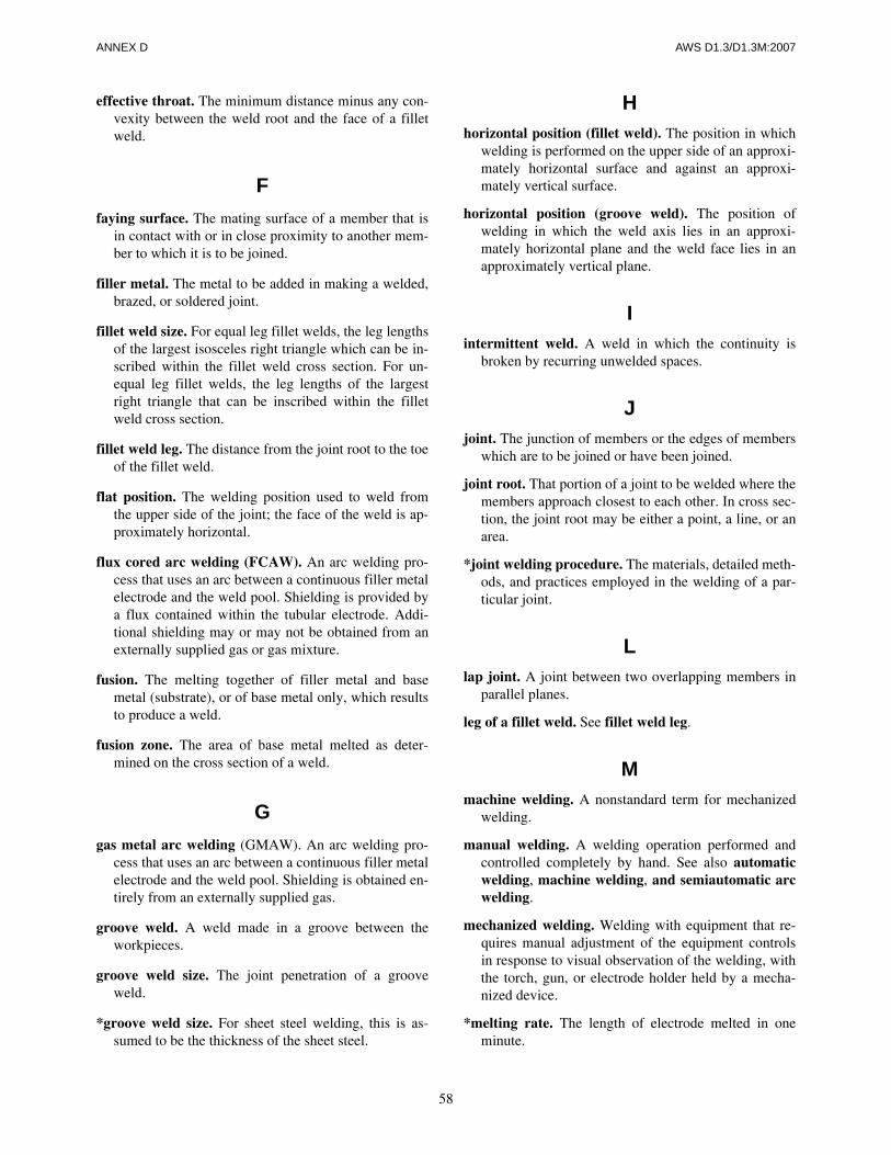
ANNEX D AWS D1.3/D1.3M:2007
58
effective throat. The minimum distance minus any con-vexity between the weld root and the face of a filletweld.
F
faying surface. The mating surface of a member that isin contact with or in close proximity to another mem-ber to which it is to be joined.
filler metal. The metal to be added in making a welded,brazed, or soldered joint.
fillet weld size. For equal leg fillet welds, the leg lengthsof the largest isosceles right triangle which can be in-scribed within the fillet weld cross section. For un-equal leg fillet welds, the leg lengths of the largestright triangle that can be inscribed within the filletweld cross section.
fillet weld leg. The distance from the joint root to the toeof the fillet weld.
flat position. The welding position used to weld fromthe upper side of the joint; the face of the weld is ap-proximately horizontal.
flux cored arc welding (FCAW). An arc welding pro-cess that uses an arc between a continuous filler metalelectrode and the weld pool. Shielding is provided bya flux contained within the tubular electrode. Addi-tional shielding may or may not be obtained from anexternally supplied gas or gas mixture.
fusion. The melting together of filler metal and basemetal (substrate), or of base metal only, which resultsto produce a weld.
fusion zone. The area of base metal melted as deter-mined on the cross section of a weld.
G
gas metal arc welding (GMAW). An arc welding pro-cess that uses an arc between a continuous filler metalelectrode and the weld pool. Shielding is obtained en-tirely from an externally supplied gas.
groove weld. A weld made in a groove between theworkpieces.
groove weld size. The joint penetration of a grooveweld.
*groove weld size. For sheet steel welding, this is as-sumed to be the thickness of the sheet steel.
Hhorizontal position (fillet weld). The position in which
welding is performed on the upper side of an approxi-mately horizontal surface and against an approxi-mately vertical surface.
horizontal position (groove weld). The position ofwelding in which the weld axis lies in an approxi-mately horizontal plane and the weld face lies in anapproximately vertical plane.
Iintermittent weld. A weld in which the continuity is
broken by recurring unwelded spaces.
Jjoint. The junction of members or the edges of members
which are to be joined or have been joined.
joint root. That portion of a joint to be welded where themembers approach closest to each other. In cross sec-tion, the joint root may be either a point, a line, or anarea.
*joint welding procedure. The materials, detailed meth-ods, and practices employed in the welding of a par-ticular joint.
Llap joint. A joint between two overlapping members in
parallel planes.
leg of a fillet weld. See fillet weld leg.
Mmachine welding. A nonstandard term for mechanized
welding.
manual welding. A welding operation performed andcontrolled completely by hand. See also automaticwelding, machine welding, and semiautomatic arcwelding.
mechanized welding. Welding with equipment that re-quires manual adjustment of the equipment controlsin response to visual observation of the welding, withthe torch, gun, or electrode holder held by a mecha-nized device.
*melting rate. The length of electrode melted in oneminute.
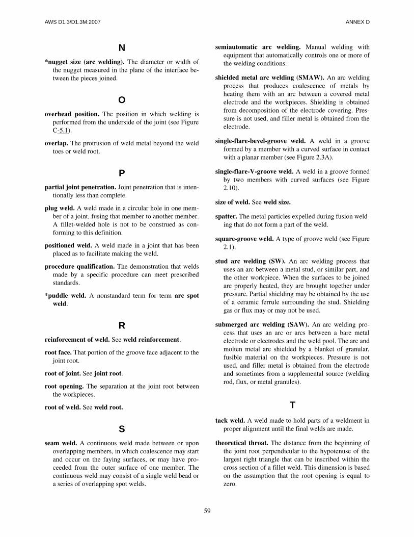
AWS D1.3/D1.3M:2007 ANNEX D
59
N*nugget size (arc welding). The diameter or width of
the nugget measured in the plane of the interface be-tween the pieces joined.
Ooverhead position. The position in which welding is
performed from the underside of the joint (see FigureC-5.1).
overlap. The protrusion of weld metal beyond the weldtoes or weld root.
Ppartial joint penetration. Joint penetration that is inten-
tionally less than complete.
plug weld. A weld made in a circular hole in one mem-ber of a joint, fusing that member to another member.A fillet-welded hole is not to be construed as con-forming to this definition.
positioned weld. A weld made in a joint that has beenplaced as to facilitate making the weld.
procedure qualification. The demonstration that weldsmade by a specific procedure can meet prescribedstandards.
*puddle weld. A nonstandard term for term arc spotweld.
Rreinforcement of weld. See weld reinforcement.
root face. That portion of the groove face adjacent to thejoint root.
root of joint. See joint root.
root opening. The separation at the joint root betweenthe workpieces.
root of weld. See weld root.
Sseam weld. A continuous weld made between or upon
overlapping members, in which coalescence may startand occur on the faying surfaces, or may have pro-ceeded from the outer surface of one member. Thecontinuous weld may consist of a single weld bead ora series of overlapping spot welds.
semiautomatic arc welding. Manual welding withequipment that automatically controls one or more ofthe welding conditions.
shielded metal arc welding (SMAW). An arc weldingprocess that produces coalescence of metals byheating them with an arc between a covered metalelectrode and the workpieces. Shielding is obtainedfrom decomposition of the electrode covering. Pres-sure is not used, and filler metal is obtained from theelectrode.
single-flare-bevel-groove weld. A weld in a grooveformed by a member with a curved surface in contactwith a planar member (see Figure 2.3A).
single-flare-V-groove weld. A weld in a groove formedby two members with curved surfaces (see Figure2.10).
size of weld. See weld size.
spatter. The metal particles expelled during fusion weld-ing that do not form a part of the weld.
square-groove weld. A type of groove weld (see Figure2.1).
stud arc welding (SW). An arc welding process thatuses an arc between a metal stud, or similar part, andthe other workpiece. When the surfaces to be joinedare properly heated, they are brought together underpressure. Partial shielding may be obtained by the useof a ceramic ferrule surrounding the stud. Shieldinggas or flux may or may not be used.
submerged arc welding (SAW). An arc welding pro-cess that uses an arc or arcs between a bare metalelectrode or electrodes and the weld pool. The arc andmolten metal are shielded by a blanket of granular,fusible material on the workpieces. Pressure is notused, and filler metal is obtained from the electrodeand sometimes from a supplemental source (weldingrod, flux, or metal granules).
T
tack weld. A weld made to hold parts of a weldment inproper alignment until the final welds are made.
theoretical throat. The distance from the beginning ofthe joint root perpendicular to the hypotenuse of thelargest right triangle that can be inscribed within thecross section of a fillet weld. This dimension is basedon the assumption that the root opening is equal tozero.

ANNEX D AWS D1.3/D1.3M:2007
60
T-joint. A joint between two members located approxi-mately at right angles to each other in the form of a T(see Figure 2.8B).
throat of a fillet weld. See actual throat, effectivethroat, and theoretical throat.
*throat of a fillet weld. For sheet steel welding, this isassumed to be the thickness of the sheet steel.
throat of a groove weld. A nonstandard term for grooveweld size.
toe of weld. See weld toe.
Uundercut. A groove melted into the base metal adjacent
to the weld toe or weld root and left unfilled by weldmetal.
Vvertical position. The position of welding in which the
weld axis is approximately vertical.
W*weld washer. A washer used for containing arc spot
welds on sheet metal thinner than 0.028 in [0.7 mm].
weld. A localized coalescence of metals or nonmetalsproduced either by heating the materials to the weld-ing temperature, with or without the application ofpressure, or by the application of pressure alone, withor without the use of filler metal.
*weld. As applied here to sheet metal welding, a local-ized coalescence of metal produced by heating to suit-able temperatures with or without the use of filler
metal. The filler metal has a melting point approxi-mately the same as the base metals.
weld axis. A line through the length of a weld, perpen-dicular to and at the geometric center of its crosssection.
welder. One who performs a manual or semiautomaticwelding operation.
welder performance qualification. The demonstrationof a welder’s ability to produce welds meeting pre-scribed standards.
welding machine. Equipment used to perform the weld-ing operation: For example, spot welding machine,arc welding machine, and seam welding machine.
welding operator. One who operates machine or auto-matic welding equipment.
welding procedure. The detailed methods and practicesinvolved in the production of a weldment. See alsowelding procedure specification.
welding procedure specification (WPS). A documentproviding, in detail, the required variables for a spe-cific application to assure repeatability by properlytrained welders and welding operators.
weldment. An assembly whose component parts arejoined by welding.
weld reinforcement. Weld metal in excess of the quan-tity required to fill a joint. See also face reinforce-ment and root reinforcement.
weld root. The points, as shown in cross section, atwhich the back of the weld intersects the base metalsurfaces.
weld size. See groove weld size and fillet weld size.
weld toe. The junction of the weld face and the basemetal.
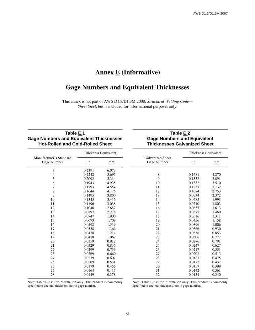
AWS D1.3/D1.3M:2007
61
Table E.1Gage Numbers and Equivalent Thicknesses
Hot-Rolled and Cold-Rolled Sheet
Manufacturer’s StandardGage Number
Thickness Equivalent
in mm
3456789
10111213141516171819202122232425262728
0.23910.22420.20920.19430.17930.16440.14950.13450.11960.10460.08970.07470.06730.05980.05380.04780.04180.03590.03290.02990.02690.02390.02090.01790.01640.0149
6.0735.6955.3144.9354.5544.1763.8003.4163.0382.6572.2781.9001.7091.5191.3661.2141.0620.9120.8360.7590.6600.6070.5310.4550.4170.378
Note: Table E.1 is for information only. This product is commonlyspecified to decimal thickness, not to gage number.
Table E.2Gage Numbers and EquivalentThicknesses Galvanized Sheet
Galvanized SheetGage Number
Thickness Equivalent
in mm
89
1011121314151617181920212223242526272829303132
0.16810.15320.13820.12330.10840.09340.07850.07100.06350.05750.05160.04560.03960.03660.03360.03060.02760.02470.02170.02020.01870.01720.01570.01420.0134
4.2703.8913.5103.1322.7532.3721.9931.8031.6131.4601.3111.1581.0060.9300.8530.7770.7010.6270.5510.5130.4750.4370.3990.3610.340
Note: Table E.2 is for information only. This product is commonlyspecified to decimal thickness, not to gage number.
Annex E (Informative)
Gage Numbers and Equivalent Thicknesses
This annex is not part of AWS D1.3/D1.3M:2008, Structural Welding Code—Sheet Steel, but is included for informational purposes only.

This page is intentionally blank.
62
AWS D1.3/D1.3M:2007
AWS D1.3/D1.3M:2007
63
This annex covers many of the basic elements of safetygeneral to arc welding processes. It includes many, butnot all, of the safety aspects related to structural welding.The hazards that may be encountered and the practicesthat will minimize personal injury and property damageare reviewed here.
F1. Electrical HazardsElectric shock can kill. However, it can be avoided. Liveelectrical parts should not be touched. Read and under-stand the manufacturer’s instructions and recommendedsafe practices. Faulty installation, improper grounding,and incorrect operation and maintenance of electricalequipment are all sources of danger.
All electrical equipment and the workpiece should begrounded. A separate connection is required to groundthe workpiece. The work lead should not be mistaken fora ground connection.
To prevent shock, the work area, equipment, and cloth-ing should be kept dry at all times. Dry gloves and rubbersoled shoes should be worn. The welder should stand ona dry board or insulated platform.
Cables and connectors should be kept in good condition.Worn, damaged, or bare cables should not be used. Incase of electric shock, the power should be turned offimmediately. If the rescuer must resort to pulling the vic-tim from the live contact, nonconducting materialsshould be used. A physician should be called and CPRcontinued until breathing has been restored, or until aphysician has arrived (see References 8, 7, and 10).
F2. Fumes and GasesMany welding, cutting, and allied processes producefumes and gases which may be harmful to one’s health.Fumes and solid particles originate from welding con-sumables, the base metal, and any coatings present on thebase metal. Gases are produced during the welding pro-cess or may be produced by the effects of processradiation on the surrounding environment. Everyoneassociated with the welding operation should acquaintthemselves with the effects of these fumes and gases.
The possible effects of over-exposure to fumes and gasesrange from irritation of eyes, skin, and respiratory systemto more severe complications. Effects may occur imme-diately or at some later time. Fumes can cause symptomssuch as nausea, headaches, dizziness, and metal fumefever.
Sufficient ventilation, exhaust at the arc, or both, shouldbe used to keep fumes and gases from breathing zonesand the general work area.
For more detailed information on fumes and gases pro-duced by the various welding processes, see References1, 4, and 11.
F3. NoiseExcessive noise is a known health hazard. Exposure toexcessive noise can cause a loss of hearing. This loss ofhearing can be either full or partial, and temporary orpermanent. Excessive noise adversely affects hearingcapability. In addition, there is evidence that excessivenoise affects other bodily functions and behavior.
Annex F (Informative)
Safe Practices
This annex is not part of AWS D1.3/D1.3M:2008, Structural Welding Code—Sheet Steel, but is included for informational purposes only.
ANNEX F AWS D1.3/D1.3M:2007
64
Personal protective devices such as ear muffs or earplugs may be employed. Generally, these devices areonly accepted when engineering controls are not fullyeffective (see References 1, 5, and 11).
F4. Burn ProtectionMolten metal, sparks, slag, and hot work surfaces areproduced by welding, cutting, and allied processes.These can cause burns if precautionary measures are notused.
Workers should wear protective clothing made of fire-resistant material. Pant cuffs or clothing with open pock-ets or other places on clothing that can catch and retainmolten metal or sparks should not be worn. High-topshoes or leather leggings and fire-resistant gloves shouldbe worn. Pant legs should be worn over the outside ofhigh-top boots. Helmets or hand shields that provide pro-tection for the face, neck, and ears, should be worn, aswell as a head covering to protect the head.
Clothing should be kept free of grease and oil. Combusti-ble materials should not be carried in pockets. If anycombustible substance is spilled on clothing, it should bereplaced with clean fire resistant clothing before workingwith open arcs or flame.
Appropriate eye protection should be used at all times.Goggles or equivalent also should be worn to give addedeye protection.
Insulated gloves should be worn at all times when mak-ing contact with hot items or handling electrical equip-ment.
For more detailed information on personal protectionReferences 2, 3, 8, and 11 should be consulted.
F5. Fire PreventionMolten metal, sparks, slag, and hot work surfaces areproduced by welding, cutting, and allied processes.These can cause fire or explosion if precautionary mea-sures are not used.
Explosions have occurred where welding or cutting hasbeen performed in spaces containing flammable gases,vapors, liquid, or dust. All combustible material shouldbe removed from the work area. Where possible, movethe work to a location well away from combustible mate-rials. If neither action is possible, combustibles should beprotected with a cover of fire resistant material. All com-bustible materials should be removed or safely protectedwithin a radius of 35 ft [11 m] around the work area.
Welding or cutting should not be done in atmospherescontaining dangerously reactive or flammable gases,vapors, liquid, or dust. Heat should not be applied to acontainer that has held an unknown substance or a com-bustible material whose contents when heated can pro-duce flammable or explosive vapors. Adequateventilation should be provided in work areas to preventaccumulation of flammable gases, vapors or dusts. Con-tainers should be cleaned and purged before applyingheat.
For more detailed information on fire hazards from weld-ing and cutting operations, see References 6, 8, 9, and11.
F6. Radiation
Welding, cutting, and allied operations may produceradiant energy (radiation) harmful to health. Everyoneshould acquaint themselves with the effects of this radi-ant energy.
Radiant energy may be ionizing (such as X-rays) or non-ionizing (such as ultraviolet, visible light, or infrared).Radiation can produce a variety of effects such as skinburns and eye damage, if excessive exposure occurs.
Some processes such as resistance welding and coldpressure welding ordinarily produce negligible quantitiesof radiant energy. However, most arc welding and cut-ting processes (except submerged arc when used prop-erly), laser welding and torch welding, cutting, brazing,or soldering can produce quantities of nonionizing radia-tion such that precautionary measures are necessary.
Protection from possible harmful radiation effectsinclude the following:
(1) Welding arcs should not be viewed exceptthrough welding filter plates (see Reference 2). Trans-parent welding curtains are not intended as welding filterplates, but rather, are intended to protect passersby fromincidental exposure.
(2) Exposed skin should be protected with adequategloves and clothing as specified (see Reference 8).
(3) The casual passerby to welding operations shouldbe protected by the use of screens, curtains, or adequatedistance from aisles, walkways, etc.
(4) Safety glasses with ultraviolet protective sideshields have been shown to provide some beneficial pro-tection from ultraviolet radiation produced by weldingarcs.

AWS D1.3/D1.3M:2007 ANNEX F
65
References Cited
1. American Conference of Governmental IndustryHygienists (ACGIH). Threshold limit values forchemical substances and physical agents in theworkroom environment. Cincinnati, Ohio: AmericanConference of Governmental Industry Hygienists(ACGIH).
2. American National Standards Institute. Practice foroccupational and educational eye and face protec-tion, ANSI/ASC Z87.1. New York: AmericanNational Standards Institute.
3. ——. Personal Protection—Protective Footwear,ANSI/ASC Z41.1. New York: American NationalStandards Institute.
4. American Welding Society. Fumes and gases in thewelding environment, AWS report. Miami, Florida:American Welding Society.
5. ——. Method for sound level measurement of man-ual arc welding and cutting processes, ANSI/AWSF6.1. Miami, Florida: American Welding Society.
6. ——. Recommended safe practices for the prepara-tion for welding and cutting containers and piping,ANSI/AWS F4.1. Miami, Florida: American Weld-ing Society.
7. ——. Safe Practices. (Reprint from Welding Hand-book, Volume 1, Eighth Edition) Miami, Florida:American Welding Society.
8. ——. Safety in welding, cutting, and allied pro-cesses. ANSI Z49.1. Miami, Florida: AmericanWelding Society.
9. National Fire Protection Association. Fire preven-tion in use of cutting and welding processes, NFPAStandard 51B. Quincy, Massachusetts: National FireProtection Association.
10. ——. National Electrical Code. NFPA No. 70.Quincy, Massachusetts: National Fire ProtectionAssociation.
11. Occupational Safety and Health Administration.Code of Federal Regulations, Title 29 Labor,Chapter XVII, Subtitle B Part 1910; OccupationalSafety and Health Standards. Washington, DC: U.S.Government Printing Office.

This page is intentionally blank.
66
AWS D1.3/D1.3M:2007
AWS D1.3/D1.3M:2007
67
The following applicable general specifications andjournal article are cited for information only.
1. American Concrete Institute—Building CodeRequirements for Reinforced Concrete ACI 318.
2. American Iron and Steel Institute—Specification forthe Design of Cold-Formed Steel Structural Members
3. American Institute of Steel Construction—Specifi-cation for the Design, Fabrication, and Erection ofStructural Steel for Buildings.
4. AWS Welding Journal, December, 1987 pages 17–31 “Calculated Cooling Rates of Arc Spot Welds”authored by Omer Blodgett.
Annex G (Informative)
Reference Documents
This annex is not part of AWS D1.3/D1.3M:2008, Structural Welding Code—Sheet Steel, but is included for informational purposes only.

This page is intentionally blank.
68
AWS D1.3/D1.3M:2007
AWS D1.3/D1.3M:2007 COMMENTARY
69
Commentary on
Structural Welding
Code—Sheet Steel4th Edition
Prepared by theAWS D1 Committee on Structural Welding
Under the Direction of theAWS Technical Activities Committee
Approved by theAWS Board of Directors

This page is intentionally blank.
70
AWS D1.3/D1.3M:2007

AWS D1.3/D1.3M:2007
71
The purpose of the commentary is to provide informationand background data supporting the provisions of someclauses of this specification. These clauses are dulyidentified.
C-1.1 ScopeIn terms of types of welds, this specification covers thefollowing:
(1) Welds customarily used in production work
(2) Welds for which conventional methods of mea-suring sizes cannot be used.
NOTE: The constructive response of the users (design-ers, fabricators, etc.) in each of the areas covered by thespecification is greatly encouraged.
The following will amplify the above statements.
By definition, a plug weld is a circular weld in a lap jointmade through a hole in one member. In this specifica-tion, the equivalent provisions are also made for arc spotwelds; these are circular welds fused through one sheetonto supporting material without the use of a hole. Toobtain proper penetration and fusion between the
two materials, it is necessary to use sufficient weldingcurrent.
Also, the size of a fillet weld in a T-corner, or lap joint inthick material can be measured with suitable gages, andthe allowable load capacity is based on the theoreticalthroat which is the shortest distance between the root ofthe joint, and the face of the diagrammatic weld. In thiscase, it is assumed that the weld is as strong as the mate-rial to which it is attached because of the relativelydeeper penetration; therefore, the allowable load capac-ity of the joint will essentially depend upon the thicknessof the material, its strength, and the length of the weld.
C-1.4.4.1 AWS Specification. AWS A5.1/A5.1Mand AWS A5.5/A5.5M specifications cover mild steeland low-alloy electrodes.
It is possible to produce satisfactory welds in sheet metalwith electrodes of many types. However, some electrodeclassifications have better penetration than others andassist naturally in making arc spot welds and arc seamwelds. Other electrode classifications are noted for theirlimited penetration and lesser tendency for undercuttingand, therefore, would perform better on fillet and flare-groove welds on thinner materials.
Commentary on
Structural Welding Code—Sheet Steel
NOTE: All references to numbered subclauses, tables, and figures, unless otherwise indicated, refer to subclauses, tables,or figures in AWS D1.3/D1.3M:2008, Structural Welding Code—Sheet Steel. References to subclauses, tables, or figuresin this Commentary are prefixed with a C-.
C-1. General Requirements

This page is intentionally blank.
72
AWS D1.3/D1.3M:2007
AWS D1.3/D1.3M:2007
73
C-2.2.2 Fillet Welds. Presently, the allowable stress forfillet welds in static applications other than in sheet steelis based on 0.30 of the minimum specified tensilestrength of the weld metal (0.30 Fxx). This stress isassumed to be applied on the throat of the fillet (t) irre-spective of the direction of the applied loads. For fusionfaces having an included angle of 90°, the throat (t) isequal to 0.707 times the leg size (w). The allowable shearstress of the throat of the weld is Fw = 0.30 (Fxx) (see Fig-ure C-2.1). However, AWS D1.1, Structural WeldingCode—Steel, also recognizes that the allowable stress ofthe attaching plate shall not be exceeded.
However, the behavior of fillet welded joints in sheetsteel is markedly different. The strength of the weld doesnot usually govern the capacity of the joint, because itusually has a strength greater than the sheet steel. This isdue to the weld metal having typically greater strengththan the sheet steel, to the large amount of penetration (inT-joints), and to typically convex weld profile. For thisreason, calculations of the load capacity of a fillet-welded joint in sheet steel are based on thickness and onthe specified minimum tensile strength of the sheet steelimmediately adjacent to the weld (see Figure C-2.2 andEquations (1), (2), and (3), which give the load capacitiesfor such joints). Equations (1), (2), and (3) have beenestablished as result of research conducted on galvanizedsheet steel lap joints where the maximum thickness ofthe cover sheet was 12 Ga. (0.108 in) [2.74 mm].
Research data have indicated that in longitudinallyloaded fillet welds, the unit load capacity for shorter filletwelds is greater than that calculated in Equation (3) andhas led to the empirical Equation (2). Equation (4) coverscases where joint capacity is governed by weld strength.The relation tw < t may occur in T-joints and in lap joints,especially in cases where cover plate is thicker than 12 Ga.(0.108 in) [2.74 mm] and single pass weld is used.
C-2.2.4 Arc Spot Welds. As already noted in C1.1,an arc spot weld resembles a plug weld on plate, exceptthat the sheet material is not punched and the weld metal
is fused through the sheet into the supporting material ormember. For plate welding, the strength of a plug welddepends upon the cross-sectional area of the weld fusedwith the surface of the supporting member. For sheetsteel welding, the ratio of the diameter of the weld to thethickness of sheet material is many times larger than thatapplicable to a plug weld in plate welding. Any strengthcalculation based upon this area would be larger than theactual strength of the joint because failure would occurby the tearing of the sheet from the weld. For this reason,the load capacity of an arc spot weld in sheet steel isbased on some measurement of the diameter of the weld,and the thickness and strength of the sheet steel. This facthas been confirmed by actual testing of the welds.
The sheet steel around the circumference of the arc spotweld is subjected to various stresses as it sets up a resist-ing force. The stress in the material is a tensile stress atthe leading edge, becoming a shear stress along the sides,and eventually, becoming a compressive stress at thetrailing edge of the weld. With progressively increasingloads, the tensile stress at the leading edge will causetransverse tearing to occur in the materials next to theweld and will extend it across the material, leading toeventual failure [see Figure C-4(A)].
If the sheet steel is sufficiently thin, there may be a ten-dency for it to buckle near the trailing edge of the arcspot weld. This will decrease the resisting force of thejoint, and failure will occur initially by tension at theleading edge and, then, tearing out in shear along thesides [see Figure C-2.3(B)]. Evidence obtained fromconducted tests suggests that this buckling conditionoccurs when the following relationship exists:
There are three equations with a transition at:
dt--- 240
Fu---------≥
dt--- 140
Fu--------- and dt
--- 240Fu
---------= =
C-2. Design of Welded Connections
74
COMMENTARY AWS D1.3/D1.3M:2007
The diameter of the fused section of the weld at the faceof supporting material (de) is less than the surface diame-ter (d) of the arc spot weld. Since the surface of the weldis the only portion accessible for measurement, somereduction of this measurement must be made when cal-culating the load capacity of the weld.
A convenient way to affect this reduction, showing goodcorrelation with test results, is to subtract one thickness(t) from the outside diameter of the weld (d) [see FigureC-2.3(C)].
In the case of a double thickness of material, this reduc-tion of the outside diameter of weld (d) amounts to twicethe combined thickness of the material (t) [see Figure C-2.3(D)]. Such reduction provides a slope of 45° at the topof the weld.
For a given overall thickness, there is less heat trans-ferred through a double sheet than through a single sheet.For this reason, the average diameter (da) and the effec-
tive diameter, (de) will be smaller when a double sheet isused.
If sheet steel is galvanized, the thickness of galvanizingshould be deducted from the overall thickness of thesheet. If the thickness of the galvanizing is not shown, anarbitrary 0.0015 in [0.04 mm] should be deducted fromthe thickness of each sheet.
In cases where the effective width of the arc seam weldbecomes too small, as shown in Figure C-2.4, it is possi-ble for the weld to shear out of the base metal. The fol-lowing equation provides a lower bound, intended topreclude such failure.
where
de = 0.7d – 1.5t
Pde( )2
4------------
Lde3
--------+ Fxx=

75
AWS D1.3/D1.3M:2007 COMMENTARY
Figure C-2.1—Allowable Stressfor Fillet Welds Figure C-2.2—Load Capacity of Fillet Welds
Figure C-2.3—Arc Spot Welds

76
COMMENTARY AWS D1.3/D1.3M:2007
Figure C-2.4—Arc Seam Weld in a Supporting Plate
AWS D1.3/D1.3M:2007
77
C-4.5 Essential Variable LimitationsNOTE: Permissible ranges for variations of other vari-ables have not been introduced into this code at thistime. This omission is due to insufficient data availableto support such ranges. It is anticipated that the use ofthis code will result in the flow of information which willeventually provide a basis for appropriate modifications.
C-4.6.4 Arc Spot Welds. The objective of the require-ment of 4.6.4 is to check on the ability of the electrode toproduce sound welds in rapid succession at elevatedcurrent levels characteristic of currents used in makingspot welds. At the relatively high current, the coating ofsome covered electrodes may break down and, as aresult, produce penetration more shallow than thatrequired. This tendency may be rectified by limiting thenumber of welds made in rapid succession with oneelectrode.
The required current level shall have been establishedduring the procedure qualification testing program. Thecurrent shall be used to measure the electrode meltingrate as described here, which shall therefore be used togive evidence that the proper current level is being usedin production welding.
C-4.6.4.4 SMAW Melting Rate. Melting rate as amethod of measuring welding current has long been in
use. Many published shielded metal arc welding(SMAW) procedures still include the melting rate (M)along with the welding current and other data needed.
Once the welding current for a given size and classifica-tion of SMAW electrode has been established, thewelder should place a new electrode into its holder. Thewelder should proceed to weld at this current level forone minute (60 seconds) and then measure the length ofelectrode melted during this time interval. This can eas-ily be done by placing a steel measuring tape along theelectrode stub, as shown in Figure C-4.1. The tape ispositioned so that the number representing the initiallength of the electrode is lined up with the end of theelectrode in the holder (position 1). The number on theside which is opposite the melted end of the electrodeshould then be read (position 2). This number representsthe electrode melting rate in inches per minute, and isdesignated (M).
For most welding procedures on sheet steel, it will takeless than 60 seconds to melt off the electrode. In such acase, a shorter welding time should be used. For exam-ple, the electrode may be melted for 30 seconds, and themelted length of electrode should be multiplied by two.A 20 second period may be used with a multiplier ofthree, or a 15 second period, with a multiplication factorof four.
C-4. Workmanship
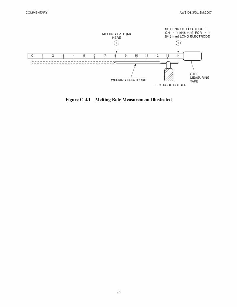
78
COMMENTARY AWS D1.3/D1.3M:2007
Figure C-4.1—Melting Rate Measurement Illustrated
AWS D1.3/D1.3M:2007
79
C-5.3.1 Joint Detail Positions. Position of welding. Thesketches in Figure C-5.1 should assist in the properunderstanding of the positions of welding.
C-5.3.3 Commercially available backing rings are com-monly made of ASTM A 109 Temper 3 or 4.
C-5.4 Allowable Deviation from WPS for LowerTemperatures using Annex A, Note 1. These adjust-ments to WPSs qualified at room temperature andapplied a much lower temperature are based on the “Cal-culated Cooling Rates of Arc Spot Welds” work byOmer Blodgett. In the referenced works performed inCanada, it was found that it was not always possible toincrease the welding current for a given welding elec-trode size the amount necessary to achieve the requiredwelding current increase for the lower temperature. Thisshould be considered when extending the applicationtemperature range. For arc spot welds and arc plugwelds, the best solution may be a combination ofincreased current and increased weld time. For arc seamwelds, the best solution may be a combination ofincreased welding current and decreased travel speed.
C-5.4.1 and C-5.4.2 Arc Spot and Arc Seam Welds.Arc spot welding and arc seam welding are commonlyused to attach sheet steel material, such as roof deckingand floor decking, to thicker structural members. Pre-heating is generally not used. A number of researchstudies1 on arc spot welds have been made by the Cana-dian Sheet Steel Industries Construction Council, theCanadian Sheet Steel Building Institute, and the WeldingInstitute of Canada to determine the strength of weldsand their effect on the strength and fracture resistance ofthe underlying structural steel.
Computer analysis2 has shown the same cooling rate willbe obtained down to 32°F [0°C] by increasing the weld-ing time by 20% or by increasing the amperage settingsby 10%.
1 Thorn, K., et al. Fracture tests on arc spot welds. ReportRC163 for Canadian Sheet Steel Building Institute. Oakville,Ontario: Welding Institute of Canada, May 1986.2 Blodgett, O. W. Calculated cooling rates of arc spot welds.Paper presented at 68th Annual AWS Meeting, Chicago,Illinois. March 1987.
C-5. Technique
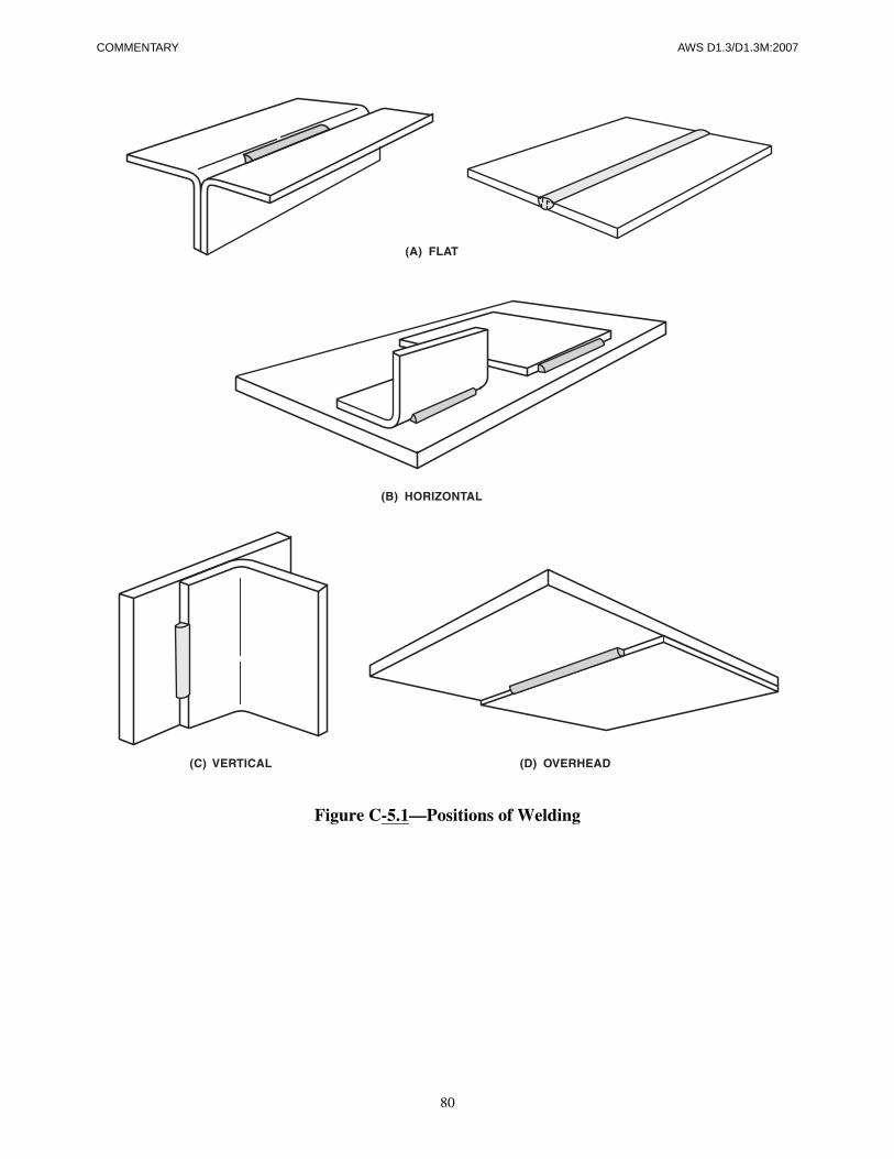
80
COMMENTARY AWS D1.3/D1.3M:2007
Figure C-5.1—Positions of Welding
AWS D1.3/D1.3M:2007
81
C-A. Applicable Provision Requirements When WeldingD1.3 Sheet Steels to D1.1Other Steel Product Forms
Subclause 1.1 and Annex A address the simultaneousapplication of the AWS D1.1 and AWS D1.3 codes tothe welding of sheet steel to structural steel. Subclause1.1 and Annex A clearly specify the relationships be-tween AWS D1.1 and AWS D1.3. The exemptions toAWS D1.1 are clearly defined and based on specific con-nection tests (the referenced works) and associated yearsof service of existing fabricated structures. These spe-cific connection tests indicate that if welding proceduresare kept within the allowances of Annex A, welding atambient temperatures ≥0°F [–18°C] will provide soundwelds. Experience with these procedures and controlsindicates that these temperatures are adequate to avoid
localized cracking or excessive hardness and adding pre-heat is not justified (see References 1, 2, 3, and 4).
References1. Blodgett, O. W. Calculated cooling rates of arc spot
welds. Paper presented at 68th Annual AWS Meeting,Chicago, Illinois. March 1987.
2. Strength of Arc Spot Welds in Sheet Steel Construc-tion—CISCC Industry Research Project 175 (1978).
3. Study of Hardness and Cooling Rates in Arc SpotWelds—Canadian Sheet Steel Building Institute(1980).
4. Fracture Tests on Arc Spot Welds—Report RC163—Canadian Sheet Steel Building Institute (1983).
C-Annex A

This page is intentionally blank.
82
AWS D1.3/D1.3M:2007

83
AWS D1.3/D1.3M:2007 LIST OF AWS DOCUMENTS
List of AWS Documents on Structural Welding
Designation Document
D1.1/D1.1M Structural Welding Code—Steel
D1.2/D1.2 Structural Welding Code—Aluminum
D1.3/D1.3M Structural Welding Code—Sheet Steel
D1.4/D1.4M Structural Welding Code—Reinforcing Steel
D1.5/D1.5M Bridge Welding Code
D1.6/D1.6M Structural Welding Code—Stainless Steel
D1.8/D1.8M Structural Welding Code—Seismic supplement
D1.9/D1.9M Structural Welding Code—Titanium

This page is intentionally blank.
84
AWS D1.3/D1.3M:2007