STRUCTURAL TECHNIQUES FOR JOINING ... TECHNIQUES FOR JOINING FILAMENTARY COMPOSITES * G. A. Clark...
9
No. 68-1038 }v n. n r (L-:v,y) STRUCTURAL TECHNIQUES FOR JOINING FILAMENTARY COMPOSITES by G. A. CLARK and K. I. CLAYTON North American Rockwell Corporation Columbus, Ohio AIAA Paper No. 68-1038 i 3> DEPARTMENT OF DEFENSE PLASTICS TECHNICAL EVALUATION CENTER PICATINNY ARSENAL, DOVER, N. J. 1 AIAA 5th Annual Meeting and Technical Display PHILADELPHIA, PENNSYLVANIA/OCTOBER 21-24, 1968 First publication rights reserved by American Institute of Aeronautics and Astronautics. 1290 Avenue of the Americas, New York, N. Y. 10019. ' Abstracts may be published without permission if credit is given to author and to AIAA. tffin-, AIAA MomkttMlrOO. Henmi\nbijJkk58) . '% mFZZ---
Transcript of STRUCTURAL TECHNIQUES FOR JOINING ... TECHNIQUES FOR JOINING FILAMENTARY COMPOSITES * G. A. Clark...

No. 68-1038 }v n. nr
(L-:v,y)
STRUCTURAL TECHNIQUES FOR JOINING FILAMENTARY COMPOSITES
by
G. A. CLARK and K. I. CLAYTON North American Rockwell Corporation Columbus, Ohio
AIAA Paper
No. 68-1038
i
3>
DEPARTMENT OF DEFENSE PLASTICS TECHNICAL EVALUATION CENTER
PICATINNY ARSENAL, DOVER, N. J.1
AIAA 5th Annual Meeting and Technical Display PHILADELPHIA, PENNSYLVANIA/OCTOBER 21-24, 1968
First publication rights reserved by American Institute of Aeronautics and Astronautics. 1290 Avenue of the Americas, New York, N. Y. 10019. '
Abstracts may be published without permission if credit is given to author and to AIAA. tffin-, AIAA MomkttMlrOO. Henmi\nbijJkk58)
. '%
mFZZ---
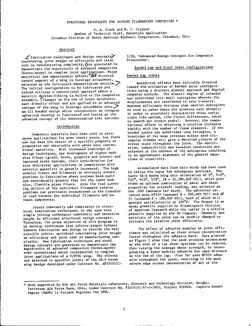
STRUCTURAL TECHNIQUES FOR JOINING FILAMENTARY COMPOSITES *
G. A. Clark and K. I. Clayton Member of Technical Staff, Materials Application
Columbus Division of North American Rockwell Corporation, Columbus, Ohio
Abstract
^Fabrication techniques and design concepts/ considering joint weight or efficiency and joint cost or manufacturing complexity, (are generated to demonstrate the superiority of advanced composites (boron-epoxy) in complex joint applications. Major analytical and experimental efforts a*£- directed toward support of a wing to fuselage attachment, selected as the full-scale demonstration article./ The initial configuration to be fabricated and tested utilizes a conventional approach where a metallic doubler-fitting is bolted to the composite assembly. fChanges in the use of boron reinforce- ment directly effect and are applied to an advanced concept of the wing to fuselage attachment area./ An all bonded design which incorporates an integral spherical bearing is fabricated and tested as the advanced concept of the demonstration test article.
Introduction
Composite materials have been used in aero- space applications for over twenty years, but their use has been the result of a specific property or properties not obtainable with other more conven- tional materials. With increased knowledge of design techniques, the development of higher mod- ulus fibers (glass, boron, graphite and others) and improved resin systems, their consideration for true structural applications in competition with metallic materials is greatly increased. The high modulus fibers and filaments do obviously create problems in fabrication where minimum bend radii are considerably greater than for the lower mod- ulus, flexible glass fibers. Also the load carry- ing ability of the individual filaments creates problems not previously encountered in the transfer of load between the individual filaments and be- tween components.
Joints inherently add complexity to struc- tural fabrication techniques; in the same vein simple joining techniques inherently add excessive weight to efficient structural design concepts. Therefore, the prime objective of this program is to develop techniques that achieve proper balance between fabrication and design to provide the best possible joints, optimized considering joint weight or efficiency and joint cost or manufacturing com- plexity. New fabrication techniques and novel design concepts are generated to demonstrate the superiority of advanced composites (boron-epoxy) over conventional metal construction in complex joint applications of a V/STOL wing. The efforts are directed to specific joints of the CX-6 boron wing design developed under Contract No. AF33(615)-
5150, »Advanced Design Concepts for Composite Structures".
Bonded Lap and Scarf Joint Configurations
Bonded Lap Joints
Analytical efforts were initially directed toward the evaluation of bonded joint configura- tions using a discrete element approach and digital computer methods. The elastic region of interest was subdivided into small subregions wherein the displacements are considered to vary linearly. Maximum efficiency dictates that smaller subregions be used in areas where the stresses vary abruptly in order to accurately characterize these varia- tions (the method, like finite differences, tends to smooth out stress peaks). However, the compu- tational effort in obtaining a solution increases rapidly with the number of these elements. If the bonded joints are subdivided into triangles, a knowledge of the mean stresses within each tri- angular element will give a detailed picture of the stress state throughout the joint. The equili- brium, compatibility and boundary conditions are enforced at the corners of the subregions resulting in an approximate statement of the general equa- tions of elasticity.
Accumulated data from this study has been used to refine the input for subsequent analyses. The basic CX-6 boron wing skin orientation of 0°, "tl0°, -t20°, ±25°, ±35°, (E = 21,280,000 PSI), which pro- vides an optimum combination of axial and shear properties for aircraft loading, was selected as the .090 laminate for study. The adhesives se- lected were HT424 (assumed E = 395,000 PSI) and AF 31 (assumed E = 180,000 PSI), both of which will operate satisfactorily at 350°F. The former is an epoxy phenolic supplied by Bloomingdale Division
. of American Cyanamid while the latter is a nitrile phenolic supplied by the 3M Company. Geometry and materials of the joint can be readily changed to evaluate the relative joint efficiency.
The effect of adhesive modulus on joint effi- ciency was calculated as shear stress concentration factor throughout the adhesive bond. Data plotted as Figure 1 show that the peak stresses encountered at the ends of a lap shear specimen can be reduced, thus raising the average shear strength, by incor- porating a lower modulus adhesive for some distance at the end of the lap. Plot "A" uses HT424 adhe- sive throughout the joint, resulting in the most severe edge stress concentration of any of the
* Work supported by the Air Force Materials Laboratory, Research and Technology Division, Wright- Patterson Air Force Base, Ohio, under Contract No. F33(615)-67-C-1802, Project 6169CW. Captain Robert
Rapson (MACM) is Project Engineer for AFML.

candidate joints. Plot "B" uses AF31 adhesive throughout the joint, resulting in a 32% reduction of the HT424 peak stress. It may be seen from curves "C" and "D" that the stresses vary abruptly, introducing secondary peaks, in the regions of adhesive modulus variation. However, combining a more flexible -adhesive at the joint edge with a more rigid adhesive across the center of the joint does not create any stress risers as severe as when bonding with only one adhesive; therefore an ori- entation of variable modulus adhesives within the bond line significantly improved the joint effi- ciency.
oriented boron layer is placed on the surface next to the bond line. Failure of the adhesive bond was initiated where the laminating resin was separated from the boron filament as shown in Figure 3. Double lap shear test results on metal adherends confirmed that the low modulus adhesive which has considerable plastic behavior, is. far superior at room temperature to the high modulus adhesive but only slightly better than the marriage of the two. This latter situation may not be true if the effects of fatigue, creep, or moderately elevated temper- ature are considered. Test data of multidirectional boron laminates infers that the structural potential of an adhesive bond cannot be fully utilized until the interlaminar shear and/or laminating resin to boron filament integrity is improved.
.2.5 --
.090 (TIP.)
.ooR {n?.)/—~\\
1.5
0.5 --
\-y//fy/A ©
©
©
i JE1 = 21,280,000 PSI
u i "f-2 - 395,000 P3I
KEOE, = 130,000 PEI
C 1/-' l/'i ')/>• 1/-' " £ J"1M
i,;j:AXb FHOM EjGE Or' LAK1 :.A Tt. ■ i':.
STRESS CONCENTRATION FACTOR - KPFKOT OF ADHrSIVK MODULUS (LAP JOINT)
FIGURE 1
Bonded single lap shear specimens were fabri- cated and tested in an initial attempt to verify the analytical study of the lap type joints. The 3M Company's boron prepreg tape, "Scotchply" SP272, was selected for the experimental effort. This material is a three inch wide unidirectional boron tape of .005 inches thickness, having 210 filaments per inch, and carried on style 104 glass scrim. The results of all AF31-HT424 systems were compar- able since all failures took place within the boron laminate structure itself and not in the adhesive bond. Apparently failure was induced by a peeling of the outer plies (-35°) of boron fibers from the composite adherend as shown in Figure 2. Experi- mental results of additional lap shear test specimens, reversing the order of laminate layup, showed an increase in strength when a zero degree
FIGURE 2. BONDED LAP JOINT-TYPICAL INTERLAMINAR SHEAR FAILURE
Bonded Scarf Joints
An analytical study, similar to that performed on lap joints, was made using the configuration of the CX-6 wing skin splice at Station 309 as the four inch scarf joint under study. Boron and glass inserts were investigated for a .400 inch thick sandwich panel with .040 inch thick face sheets of the basic CX-6 wing skin orientation. Modulus values of 3,000,000 psi for the glass insert and 9,750,000 psi for the boron insert were assumed for

non-continuous randomly oriented reinforcement. It was determined that the solid glass insert creates a significantly higher edge stress riser than does a boron insert when using either AF31 or HT424 adhesive throughout the joint or when using a mixed modulus adhesive system. The closer the exten- sional stiffness of the insert matches the face sheets, the more efficient is the joint. The vari- able modulus adhesive system fails to offer the marked improvement to the bonded scarf joint, and also introduces secondary stress peaks at the points of adhesive modulus variation. However, in- troducing a more flexible adhesive at the joint edge still produces a more efficient joint than when using a rigid adhesive throughout the joint.
program.
Wing to Fuselage Attachment
FIGURE 3. DETAIL OF SURFACE FAILURE-LAP SHEAR SPECIMEN
A laboratory program was established and specimens developed to determine the load carrying capability of such concepts in pure tensile and pure shear loading. Since an all boron insert would be costly, a boron-glass combination insert was considered and its fabrication accomplished by laying up one ply of 0° boron and one ply of 90° boron between each layer of 181 style glass fabric in a repeating sequence. The scarf was machined with a single point diamond cutter. The faying surfaces of the facings, inserts, and scarf area were prepared for bonding by light scuff sanding and a solvent wipe. A stronger bond was produced with the higher modulus boron-glass insert than with a solid glass insert; verifying the analytical
Conventional Concept
The CX-6 wing semi-span is approximately 408 inches with a skin splice located at Wing Station 309. The total root chord is 289 inches tapering to a tip chord of 159 inches witfr^he basic wing structure occupying approximately the forward 707. of the chord and the flaps and ailerons comprising the rest of the wing.
The initial design concept of the CX-6 inte- gral-fan wing structure consists of an unswept three-cell wing with the loads being carried by the fore and aft cells. The interior cell houses the lift fans and represents the major portion of the cross-section area. However, the large fan cutouts required on the upper and lower surface reduce its torsional effectivity and negate its use in resist- ing wing spanwise bending. The three cells are utilized to resist torsional moments and provide torsional stiffness while the spanwise bending is totally supported by the fore and aft cells. The vertical shear is supported by four vertical spar webs.
The critical design condition for this wing is a 3g symmetrical pull-out. The wing bending loads are assumed to be distributed 60 percent to the
rear cell and 40 percent to the forward cell.
The wing is mated to the fuselage through fit- tings attached to the wing at each main spar location. The fittings at the forward spar, for- ward intermediate spar and the rear spar are designed to resist both vertical and side loads while the fitting at the rear intermediate spar is designed to resist vertical and drag loads. All wing to fuselage attach fittings are bolted to the spar and the lower wing-skin sandwich panels. Major effort was directed toward the design, analysis, fabrication and testing of the forward wing to fuselage attach fitting (aft torque box) which had been selected as the full-scale demonstration ar- ticle under study (Figure 4).
Numerical methods incorporated into a high- speed computer program have been developed for the failure analysis of a multiple-plate, multiple- fastener or adhesive joint or splice under any uniform or non-uniform temperature distribution and have been applied to the wing to fuselage attach- ment. The analysis, based on virtual work methods, applied equally well to mechanically fastened joints, bonded joints, combinations thereof, and mixed materials. This program utilizes an applied load input which is a range of loads from zero to failure and defines three particular modes of fail- ure as they occur in the joint. They are, (1) plate element strain cutoff, primarily associated with a tension failure of the sheet material; (2) ultimate bolt shear load failure, which is associ- ated entirely with the fastener; and (3) plate bearing failure which is dependent upon the fas- tener-plate combination.
The analytical methods used consider the in- elastic effects of plate element stress-strain relationships beyond the proportional limit using the non-dimensional Ramberg-Osgood equation. The

local fastener plate load-deformation character- istics are represented by the Ramberg-Osgood form of equation where load, deflection, and elastic slope are substituted for stress, strain, and mod- ulus of elasticity, respectively. Because of extremely complex states of stress locally around the hole in the plate, the shear load-deflection curves of the fastener-plate combinations can be considered as a mechanical property in much the same way as the well known stress-strain curves for materials. Since no theoretical means are available for deriving either the stress-strain curves for the plate elements or the load-deflec- tion curves for a particular joint it is necessary to perform tests on small coupons to obtain the curves required for representation throughout the elastic and inelastic regions. Data from simple test.coupons supports the selection of a Ramberg- Osgood curve as a suitable representation for the complex deformation characteristics of fastener- composite plate combinations.
CX-6 WING TO FUSELAGE ATTACHMENT
FIGURE 4
Experimental data for bearing strength was obtained from testing specimens under tension load- ing using a 1/4 inch pin diameter. The laminate chosen for the bolt bearing test specimens conforms to the basic CX-6 boron wing design requirements and the type of loading under consideration for the wing to fuselage attach joint. Bearing strengths of 89,500 psi at 4% deformation and 124,700 psi at failure were measured.
Preliminary failure analyses predicted a plate bearing failure of the boron face sheets between the upper two rows of fasteners in the fitting to spar joint at 127% ultimate load; the fitting to cover skin panel not being critical. However, the initial design allowables used were established from early data and updated values were not incor- porated until the CX-6 boron wing redesign.
The initial configuration of a wing to fuse- lage attachment to be fabricated and tested
utilizes a conventional approach to designing with composite materials, as a first generation article, where a metallic doubler-fitting is bolted to the composite assembly (Figure 5).
COMPOSITE DESIGN (BORON/EPOXY) CONVENTIONAL CONCEPT
FIGURE 5
The Demonstration Article is a major assembly composed of three basic assemblies (Figure 6). These are the spar, wing skin and intercostal and in production drawings they would be shown as in- dividual parts. Fabrication on each can run con- currently to expedite fabrication with a minimum of tools.
FIGURE 6. WING TO FUSELAGE ATTACHMENT-CONVENTIONAL CONCEPT

All details were precured and pre-machined prior to assembly. The wing skin panel consists of boron skins oriented at 0°, tio°, ±20°, ±25°, ±35°, glass Inserts and an aluminum honeycomb core. The 0.180 inch facings were laid up using SP272 boron tape to the required configuration as one unit on the skin tool, autoclave molded and cured. Details were machined to final dimension using diamond im- pregnated cutting tools. The solid glass inserts were fabricated from Type 181, E glass fabric.
The honeycomb core was machined to thickness in the unexpanded (HÖBE) condition, expanded and cut to size. Where bolts were to be inserted into the assembly, 0.625 inch holes were cut through the core and this area potted with a filled epoxy com- pound catalyzed for room temperature cure. Assem- bly was accomplished by applying HT424 to the faying surfaces of all details except a bead of foaming type HT424D was placed in the edge "V" groove of the inserts. Bonding was accomplished with vacuum bag pressure.
The spar assembly consists of cap angles, skins oriented at "t45°, doublers, insert, and core. The doublers, core and insert were fabricated using the same process as the respective counterparts in the wing skin.
A rather complex glass transition area, shown in Figure 7, was required for forming a 90° flange integral with the skin.
•the absence of diamond core drills, a hardened steel threading tap was used for drilling. The method of use was as a revolving broach where small amounts of material were removed with successively larger taps.
A static test was conducted to verify the structural integrity and fabrication quality of the wing to fuselage attachment demonstration article, by applying a vertical shear load of 61,200 pounds ultimate to the spar and an ultimate drag load of 17,000 pounds to the outer skin panel. The struc- tural test of the boron/epoxy specimen used nominally identical test loads and testing methods as would be used for a metal counterpart specimen.
The specimen was mounted to a steel fitting and to a rigid fixture for testing (Figure 8). Test loads were applied by calibrated hydraulic struts through utilization of a Marginator pressure proportioning unit which controls the ratio of con- stant and variable pressure applied to the struts. Calibrated load cells were also installed in series with the loading struts as part of the test setup. Deflection was measured by Ames dials while strain gage data were recorded on a Gilmore Strain Re- corder, providing an immediate plot of test data and a continuous check on possible yield. Test loadings were applied in increments of design limit load with strain gage readings recorded at every 20% D.L.L. up to 100% D.L.L. and then at every 10% D.L.L. up to failure.
FIBERGLASS
HONEYCOMB "
FIGURE 7. LAY-UP OF BORON-GLASS TRANSITION
All sub-assemblies and final assembly were bonded using HT424 adhesive and HT424D foam type adhesive. All surfaces for bonding were prepared by scuff sanding followed by solvent wiping until all contaminates were removed. This was applicable throughout the entire procedure.
Conventional high speed drills are not ade- quate to drill the boron composites since the drill wear is excessive and the resulting holes are usually elongated. As a measure of expediency in
Run No. 1 was conducted to 166% design limit load (D.L.L.) or 110% ultimate after which the fitting was removed and the fastener holes inspec- ted. No damage to the specimen was found. Run No. 2 was conducted to 200% ultimate without failure. At this time it was proposed to resume testing of Demonstration Article No. 1, to failure, incorpor- ating a change to the test setup. The design of the cover skin sandwich panel influenced the dis- tribution of loads between the spar and skin com- ponents. In order to better simulate the edge fixity of the wing skin panel, the jig bolts which prohibit the normal deflection that this panel would experience due to spanwise bending of the aircraft wing were omitted. Run No. 3 was then conducted at which time failure of the spar to fit- ting attachment occurred at 163%, ultimate or at a resultant load of 103,500 pounds, demonstrating the strength of a conventional bolted assembly. Edge- wise shear failure of the .050 boron spar facings along the edge of the glass doubler was the primary cause of failure.
Advanced Concept - Item No.l
The optimum redesign concept of the CX-6 wing structure incorporates significant differences from the initial concept for a resultant weight savings. Changes in the use of boron reinforcement directly affect the wing to fuselage attachment area and have been applied to the advanced concept of the Demonstration Article. The two intermediate spars carry the great majority of the spanwise bending and vertical shear loads while also providing most of the required stiffness. Unidirectional boron spar caps have been utilized to partially replace heavier cover skins, center torque box skins have been converted from boron to glass, and spar webs have been changed from glass to boron. The wing is attached to the fuselage only at the intermediate

spars, reducing the number of attach fittings from ten to six. Consequently, an all bonded design which incorporates an integral spherical bearing has been generated as the advanced concept, Item No. 1, to resist ultimate loads of 54,000 pounds vertical and 17,000 pounds drag (Figure 9).
FIGURE 8. TEST FIXTURE FOR ARTICLE #1-LOOKING AFT
The oriented boron facings for both the spars and skins were laid up at "£45 using a tool similar to the one used in the conventional concept. The same bagging, pressure application and curing tech- niques were used for these components and assembly. The only deviations or improvements over previous techniques were: (1) inserts were made oversize and machined to the required tolerance except for the wing skin laminated insert. This was machined undersize in order that continuous laminations could be placed over the flat and angled surfaces to eliminate the possibility of shearing off the area of increased thickness, (2) when the large boron skin to doubler bond was made, small (0.040 inches) holes were drilled through the doubler on 2 inch centers to permit excess adhesive to escape from the bond line. This technique reduces the pillowing effect which sometime occurs when thin materials are bonded using only vacuum bag pres- sures. Figures 10 and 11 show the details of the
spar and skin assemblies prior to bonding.
COMPOSITE DESIGN (BORON/EPOXY) ADVANCED CONCEPT
FIGURE 9
FIGURE 10. DETAILS-SPAR ASSEMBLY (ADVANCED CONCEPT)

at 160% D.L.L. or 106% ultimate.
m
FIGURE 12. COMPLETED ASSEMBLY ADVANCED CONCEPT
FIGURE 11. DETAILS-WING SKIN ASSEMBLY (ADVANCED CONCEPT)
All of the 1/2 inch mounting holes around the periphery of both the spar and wing skin were drilled using the ultrasonic silicon carbide slurry (Cavitron) method. The resulting holes were very satisfactory with very close tolerance, smooth surfaces and no delamination or fracturing of the surface on the back side. The tool life is vir- tually unlimited. Figure 12 shows the completed advanced concept assembly.
A static test was conducted to verify the structural integrity and fabrication quality of the advanced concept demonstration article. Run No. 1 was conducted to 98% design limit load (D.L.L.) at which time a cracking sound was heard and the load dumped. After 60% D.L.L. of Run No. 2, a chamfer, approximately .060 x 45°, was cut on the corner of the joint at the intersection of the spar and skin panels to eliminate interference between the speci- men and loading jig. Run No. 3 and Run No. 4 were prematurely dumped after 100% D.L.L. and 75% D.L.L., respectively, when sounds were again heard. Run No. 5 was then conducted to failure which occurred
An adhesive bond failure between the glass insert housing the spherical bearing and the glass doubler which reinforces the boron spar facings was the primary cause of failure. The non-linearity of dial gages and axial strain gages located in the area of the spar spherical bearing insert showed the yielding of the failed bond from 80%-100% D.L.L. to failure at 160% D.L.L. The spar panel was dis- assembled after failure revealing a poor bond over the area inside the attaching doublers and to some degree over the doublers themselves. The poor bond was apparently caused by excessive use of the foam- ing type HT424D for a shear tie between the core and inserts. This can be eliminated by (1) using a non-foaming type shear tie or (2) by assembly of the core-insert blanket then bonding to the skin- doubler facings.
Advanced Concept, Item No. 2
Inspection of the failed Item #1 specimen re- vealed that the wing skin panel was satisfactory in its entirety for incorporation into a second test item. Two modifications were made.to the de- sign of the Item #2 spar panel' test component; (1) at 3.85 inches each side of centerline, an .050 wide strip of boron facing/honeycomb core sandwich

panel was provided within the test section to better simulate the actual CX-6 spar configuration, and (2) the .20 glass fabric facing doubler was changed to a stiffer combined glass-boron doubler to better distribute the applied load.
Warping occurred in the doubler-skin sub- assembly due to a difference in thermal expansion coefficients between the elements being cured. High stresses were thereby induced during fabri- cation of the new spar panel assembly which resulted in resin separation from the boron fila- ments locally along the fitting to spar transition line, 3.85 inches each side of centerline. Micro- scopic examination revealed no broken filaments at the surface.
The specimen was mounted to a steel loading fitting and to a rigid fixture for testing (Figure 13). A vertical shear load of 54,000 pounds ulti- mate and a drag load of 17,000 pounds ultimate, for the spar and outer skin panel respectively, were introduced through an integral fitting rather than through the two separate Item #1 loading straps. Such a load introduction provides a more typical aircraft application rather than a limited test configuration.
inches from centerline, in line with the spherical bearing. An examination of the monitor strain gage plot, revealed good linearity up to 1740 /!"/" at 100% D.L.L. Using a modulus of 17.2 x 10⁶ psi for 0° -90° oriented SP272 boron, since the strain gage is applied parallel to the filaments on the "t45° boron facing, the measured stress level at 100% D.L.L. = Ee =(17.2 x 10⁶) (1740 x 10"6)= 29,900 psi or projected to 150% D.L.L. » 44,900 psi com- pared to the 45,200 psi predicted. Based on this excellent agreement, coupled with the absence of any appreciable yield, it was decided to resume testing and continue Run No. 2 to failure which occurred at 140% D.L.L. or 93.3% ultimate. Non- linearity of strain gage readings started between 100-120%, reflecting yielding in the area of the spar spherical bearing insert and continued to failure.
An adhesive bond failure between the glass insert housing the spherical bearing and the doubler which reinforces the boron spar facings, along with interlaminar shear failure within the glass insert itself, were the primary cause of failure leading to subsequent edgewise shear failure of the .021 boron spar facings along the previously discussed transition 1-ine, 3.85 inches from centerline. As in prior testing, the fitting to wing cover skin panel was not critical.
The successful testing of three consecutive major load carrying components demonstrate that a firm technological base is currently available to design, analyze, and fabricate primary aircraft structures using multidirectional high modulus filamentary composites.
FIGURE 13. TEST FIXTURE-ADVANCED CONCEPT, ITEM #2
Run No. 1 was conducted.to 100% D.L.L. at which time the load was reduced to 20% to check data. A predicted stress distribution for the Item #2 spar showed the highest shear stress, 45,200 psi, at ultimate load, is located 3.85