STRUCTURAL TAC - Building STRUCTURAL TAC - Building This is only to provide rationale for code...
94
8/18/06 STRUCTURAL TAC - Building This is only to provide rationale for code change proposals submitted. For final language specific to the 2004 code, more details regarding the sections in the code, and correct wording, please see the 2006 Supplement. Please see the proposed code change modifications for text submitted for consideration by the Florida Building Commission. Approved 2006 Code Modifications to the 2004 FBC with Rationale - Building 1 FBC TRACKING CHART: PROPOSED MODIFICATIONS 2006 Annual Interim Code Amendments to the 2004 Florida Building Code This chart is organized according to mod/proponent, section number, and a summary of the proposed change for modifications related to the Technical Advisory Committee’s (TAC) area of responsibility. Common designations are: Admin: Integration of the administration and enforcement portions of all codes and private swimming pool barriers. Elec: Related to Electrical codes and standards Energy: Related to the energy codes and standards Fire: Related to the Fire and life/safety issues as contained within the building code and standards. Mech: Related to the Mechanical codes and standards. PlumbGas: Related to the Plumbing, Gas and swimming pool codes and standards (except commercial pools and pool barriers). SpecOcc: Codes and related standards associated with facilities for special occupancies that are regulated by state agencies. Struc: Related to the Building code for structural, technical, and material requirements and wind standards. The proposals are listed sequentially by code section number for the base code designated. The proposed mod numbers are assigned by the BCIS web site as they are received. They are assigned to the TAC that administers that specific subject area. Notations concerning where a proposal has been assigned for action are made in the Comments column. For example, if the first proposed modification to the base code FBC-Mechanical code is for section 603.1.2 (related to duct construction), it would be assigned to the Energy TAC because the issue is with the energy chapter in the building base code. This chart can be used for quick reference and for tracking the status of proposals. Status Codes: AS = Approved as submitted AM = Approved as modified NAR = No affirmative recommendation [The proposed code modification received less than 75% of the vote.] W = Withdrawn I = Insufficient (Incomplete or does not meet criteria)
Transcript of STRUCTURAL TAC - Building STRUCTURAL TAC - Building This is only to provide rationale for code...
8/18/06 STRUCTURAL TAC - Building This is only to provide rationale for code change proposals submitted. For final language specific to the 2004 code, more
details regarding the sections in the code, and correct wording, please see the 2006 Supplement. Please see the proposed code change modifications for text submitted for consideration by the Florida Building Commission.
Approved 2006 Code Modifications to the 2004 FBC with Rationale - Building 1
FBC TRACKING CHART: PROPOSED MODIFICATIONS 2006 Annual Interim Code Amendments to the 2004 Florida Building Code
This chart is organized according to mod/proponent, section number, and a summary of the proposed change for modifications related to the Technical Advisory Committee’s (TAC) area of responsibility. Common designations are:
Admin: Integration of the administration and enforcement portions of all codes and private swimming pool barriers. Elec: Related to Electrical codes and standards Energy: Related to the energy codes and standards Fire: Related to the Fire and life/safety issues as contained within the building code and standards. Mech: Related to the Mechanical codes and standards. PlumbGas: Related to the Plumbing, Gas and swimming pool codes and standards (except commercial pools and pool barriers). SpecOcc: Codes and related standards associated with facilities for special occupancies that are regulated by state agencies. Struc: Related to the Building code for structural, technical, and material requirements and wind standards.
The proposals are listed sequentially by code section number for the base code designated. The proposed mod numbers are assigned by the BCIS web site as they are received. They are assigned to the TAC that administers that specific subject area. Notations concerning where a proposal has been assigned for action are made in the Comments column. For example, if the first proposed modification to the base code FBC-Mechanical code is for section 603.1.2 (related to duct construction), it would be assigned to the Energy TAC because the issue is with the energy chapter in the building base code. This chart can be used for quick reference and for tracking the status of proposals. Status Codes: AS = Approved as submitted AM = Approved as modified NAR = No affirmative recommendation [The proposed code modification received less than 75% of the vote.] W = Withdrawn I = Insufficient (Incomplete or does not meet criteria)
8/18/06 STRUCTURAL TAC - Building This is only to provide rationale for code change proposals submitted. For final language specific to the 2004 code, more
details regarding the sections in the code, and correct wording, please see the 2006 Supplement. Please see the proposed code change modifications for text submitted for consideration by the Florida Building Commission.
Approved 2006 Code Modifications to the 2004 FBC with Rationale - Building 2
Section/ Chapter
Rationale Summary
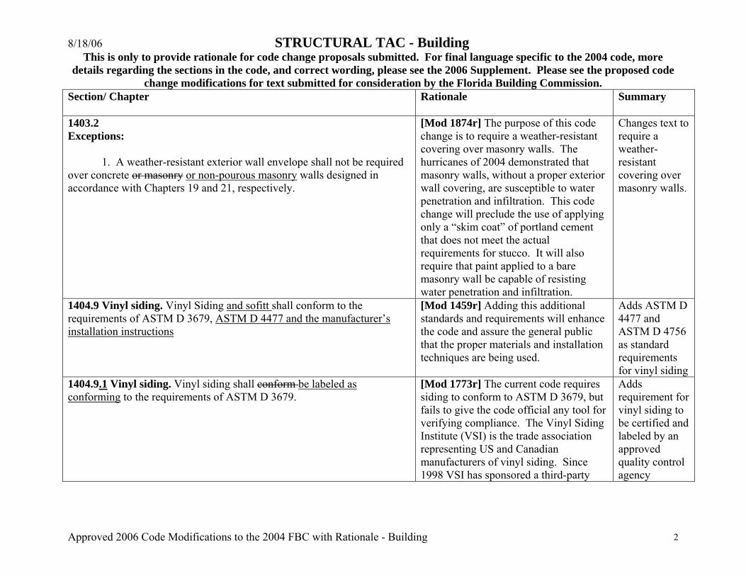
1403.2 Exceptions: 1. A weather-resistant exterior wall envelope shall not be required over concrete or masonry or non-pourous masonry walls designed in accordance with Chapters 19 and 21, respectively.
[Mod 1874r] The purpose of this code change is to require a weather-resistant covering over masonry walls. The hurricanes of 2004 demonstrated that masonry walls, without a proper exterior wall covering, are susceptible to water penetration and infiltration. This code change will preclude the use of applying only a “skim coat” of portland cement that does not meet the actual requirements for stucco. It will also require that paint applied to a bare masonry wall be capable of resisting water penetration and infiltration.
Changes text to require a weather-resistant covering over masonry walls.
1404.9 Vinyl siding. Vinyl Siding and sofitt shall conform to the requirements of ASTM D 3679, ASTM D 4477 and the manufacturer’s installation instructions
[Mod 1459r] Adding this additional standards and requirements will enhance the code and assure the general public that the proper materials and installation techniques are being used.
Adds ASTM D 4477 and ASTM D 4756 as standard requirements for vinyl siding
1404.9.1 Vinyl siding. Vinyl siding shall conform be labeled as conforming to the requirements of ASTM D 3679.
[Mod 1773r] The current code requires siding to conform to ASTM D 3679, but fails to give the code official any tool for verifying compliance. The Vinyl Siding Institute (VSI) is the trade association representing US and Canadian manufacturers of vinyl siding. Since 1998 VSI has sponsored a third-party
Adds requirement for vinyl siding to be certified and labeled by an approved quality control agency
8/18/06 STRUCTURAL TAC - Building This is only to provide rationale for code change proposals submitted. For final language specific to the 2004 code, more
details regarding the sections in the code, and correct wording, please see the 2006 Supplement. Please see the proposed code change modifications for text submitted for consideration by the Florida Building Commission.
Approved 2006 Code Modifications to the 2004 FBC with Rationale - Building 3
Section/ Chapter
Rationale Summary
program to certify compliance of vinyl siding with ASTM D 3679. This change will be published in the 2006 IBC.
1405.13 Vinyl siding. Vinyl siding conforming to the requirements of this section and complying with ASTM D 3679, and ASTM D 4477 in accordance with the manufacturer’s installation instructions shall be permitted on exterior walls of buildings of Type V construction located in areas where the basic wind speed specified in Chapter 16 does not exceed 100 miles per hour (161 km/h) and the building height is less than or equal to 40 feet (12 192 mm) in Exposure C. Where construction is located in areas where the basic wind speed exceeds 100 miles per hour (161 km/h), or building heights are in excess of 40 feet (12 192 mm), tests or calculations indicating compliance with Chapter 16 shall be submitted. Vinyl siding shall be secured to the building so as to provide weather protection for the exterior walls of the building.
[Mod 1460r] Adding this additional standards and requirements will enhance the code and assure the general public that the proper materials and installation techniques are being used.
Adds ASTM D 4477 and ASTM D 4756 as standard requirements for vinyl siding.
1503.3 Coping. Parapet walls shall be properly coped or sealed with noncombustible, weatherproof materials of a width no less than the thickness of the parapet wall. Metal coping shall comply with ANSI/SPRI ES-1 or RAS 111.
[Mod 1632r] This code change was recommended to the Commission by the Hurricane Advisory Committee during the expedited code change process held in October, 2005. At the October Commission rule hearing, this code change was deferred for consideration during the current code change cycle.
Adds requirement for metal coping to comply with ANSI/SPRI ES-1
1503.4 Roof drainage. Unless roofs are sloped to drain over roof edges, D design and installation of roof drainage systems shall comply with the Florida Building Code, Plumbing Chapter 11.
[Mod 1592] Clarifies code and refers to Plumbing Chapter 11.
Adds exception for drainage of sloped roofs
1503.4.3 Overflow scuppers When other means of drainage of overflow water is not provided, overflow scuppers shall be placed in walls or parapets not
[Mod 1593] Added the title “Overflow scuppers” to identify this subsection of
Adds title to section

8/18/06 STRUCTURAL TAC - Building This is only to provide rationale for code change proposals submitted. For final language specific to the 2004 code, more
details regarding the sections in the code, and correct wording, please see the 2006 Supplement. Please see the proposed code change modifications for text submitted for consideration by the Florida Building Commission.
Approved 2006 Code Modifications to the 2004 FBC with Rationale - Building 4
Section/ Chapter
Rationale Summary
less than 2 inches (51 mm) nor more than 4 inches (102 mm) above the finished roof covering and shall be located as close as practical to required vertical leaders or downspouts or wall and parapet scuppers. An overflow scupper shall be sized in accordance with the Florida Building Code, Plumbing.
the code.
1504.1.1 Wind resistance of asphalt shingles. Asphalt shingles shall be designed for wind speeds in accordance with Section 1507.2.7.1507.2.10. 1507.2.10 Wind Resistance of Asphalt Shingles. Asphalt Shingles shall be classified in accordance with ASTM D3161, TAS 107 or ASTM D7158 to resist the basic wind speed per Figure 1609. Shingles classified as ASTM D 3161 Class D or ASTM D 7158 Class G are acceptable for use in the 100-mph wind zone. Shingles classified as ASTM D3161 Class F, TAS107 or ASTM D 7158 Class H are acceptable for use in all wind zones. Asphalt shingle wrappers shall indicate compliance with one of the required classifications as shown in Table 1507.2.10
Table 1507.2.10 Wind Resistance of Asphalt Shingles
Maximum Basic Wind Speed MPH (per Figure1609)
Classification
100 ASTM D3161 Class D or ASTM D 7158 Class G or TAS 107
110 ASTM D3161 Class F or ASTM D 7158 Class G or TAS 107
120 ASTM D3161 Class F or ASTM D 7158 Class G or TAS 107
130 ASTM D3161 Class F or ASTM D 7158
[Mod 1785r] This change adds a new consensus standard, ASTM D7158 as an alternate test method for wind resistance of asphalt shingles. D7158 quantifies the wind uplift force and the shingle sealant’s bond strength and reflects the most up-to-date method for assessing wind performance of asphalt shingles. The resulting classifications cover wind zones from 100 mph to 150 mph. The Scope Section of ASTM D7158 (as found on www.astm.org) describes the standard as follows:
1. Scope
1.1 This test method covers the procedure for calculating the wind resistance of asphalt shingles when applied in accordance with the manufacturer's instructions, and sealed under defined conditions. The method calculates the uplift force exerted on the shingle by the action of wind at a specified velocity, and compares that to the mechanical uplift resistance of the shingle. A shingle is determined to be wind resistant at a
Replaces referenced section; Replaces fastening requirements of asphalt shingles; Adds new section and table on wind resistance of asphalt shingles; Also adds ASTM D 7158-05 as new referenced standard in chpt 35

8/18/06 STRUCTURAL TAC - Building This is only to provide rationale for code change proposals submitted. For final language specific to the 2004 code, more
details regarding the sections in the code, and correct wording, please see the 2006 Supplement. Please see the proposed code change modifications for text submitted for consideration by the Florida Building Commission.
Approved 2006 Code Modifications to the 2004 FBC with Rationale - Building 5
Section/ Chapter
Rationale Summary
Class H or TAS 107 140 ASTM D3161 Class F or ASTM D 7158
Class H or TAS 107 150 ASTM D3161 Class F or ASTM D 7158
Class H or TAS 107 Chapter 35: ASTM Standard: D7158-05 Standard Test Method for Wind Resistance of Sealed Asphalt Shingles(Uplift Force/Uplift Resistance Method)
specified basic wind speed when the measured uplift resistance exceeds the calculated uplift force for that velocity (3-second gust, ASCE 7). A mandatory wrapper labeling requirement, which is extremely important for code enforcement, has also been added along with a table which depicts the applicable standard and its classification based on the wind map. Because of Copyright issues with electronic distribution of multiple copies of ASTM Standards, a hard copy of ASTM D 7158 will be provided to the Staff.
1504.5 Edge securement for low-slope roofs. Low-slope membrane roof systems metal edge securement, except gutters, installed in accordance with Section 1507, shall be designed in accordance with ANSI/SPRI ES-1 or RAS 111 except the basic wind speed shall be determined from Figure 1609.
[Mod 1597r] Adds RAS 111 as additional resource in determining design criteria.
Adds RAS 111 as an option for determining basic wind speed for edge securement for low-slope roofs
1505.7 Special purpose roofs. Special purpose wood shingle or wood shake roofing shall conform with the grading and application requirements of Section 1507.8 or 1507.9. In addition, an underlayment of 0.625-inch (15.9 mm) Type X water-resistant gypsum backing board or gypsum sheathing shall be placed under
[Mod 1850]There have been several attempts to determine the exact application that this code section refers to, including contacting the National Roofing Contractors Association and
Deletes “Special purpose roofs” section in entirety

8/18/06 STRUCTURAL TAC - Building This is only to provide rationale for code change proposals submitted. For final language specific to the 2004 code, more
details regarding the sections in the code, and correct wording, please see the 2006 Supplement. Please see the proposed code change modifications for text submitted for consideration by the Florida Building Commission.
Approved 2006 Code Modifications to the 2004 FBC with Rationale - Building 6
Section/ Chapter
Rationale Summary
minimum nominal 0.5-inch-thick (12.7 mm) wood structural panel solid sheathing or 1-inch (25 mm) nominal spaced sheathing.
various industry groups. Additionally, there is no definition of the term “special purpose roofs” found in the Florida Building Code. Therefore, this code proposal entirely deletes this section.
1506.5 Nails. Nails shall be corrosion resistant nails conforming to ASTM F 1667. The corrosion resistance shall meet ASTM A 641, Class 1 or an equal corrosion resistance by coating, electro galvanization, mechanical galvanization, hot dipped galvanization, stainless steel, nonferrous metal and alloys or other suitable corrosion resistant material.
[Mod 1599r] This clarification came from 2001 FBC and is needed.
Adds new section on nails
1506.6 Screws Screws shall be corrosion resistant screws conforming to ANSI/ASME B 18.6.1. The corrosion resistance shall meet ASTM A 641, Class 1 or an equal corrosion resistance by coating, electro galvanization, stainless steel, nonferrous metal or other suitable corrosion resistant material.
[Mod 1601] This area needs clarification and came from 2001 FBC.
Adds new section on screws
1506.7 Clips. Clips shall be corrosion resistant clips. The corrosion resistance shall be meet 1.50 oz per sq ft (0.458 kg/m²) according to ASTM A 153 or an equal corrosion resistance coating, electro galvanization, mechanical galvanization, hot dipped galvanization, stainless steel, nonferrous metals and alloys or other suitable corrosion resistant material. Stainless steel clips shall conform to ASTM A 167, Type 304.
[Mod 1602] Clarifies the code and comes from 2001 FBC.
Adds new section on clips
TABLE 1507.2 ASPHALT SHINGLE APPLICATION
[Mod 1867] There is no need for this table because the written sections of the code clearly define the code requirement for asphalt shingles. As the code has changed, this table has not been updated and the result is several conflicts between the table and the written
Deletes “Asphalt Shingle Application” Table in its entirety

8/18/06 STRUCTURAL TAC - Building This is only to provide rationale for code change proposals submitted. For final language specific to the 2004 code, more
details regarding the sections in the code, and correct wording, please see the 2006 Supplement. Please see the proposed code change modifications for text submitted for consideration by the Florida Building Commission.
Approved 2006 Code Modifications to the 2004 FBC with Rationale - Building 7
Section/ Chapter
Rationale Summary
sections of the code. If this table stays in the code, it will have to be updated based on adopted code modifications to the referenced written sections.
1507.2.9.3 Drip edge. Provide drip edge at eaves and gables of shingle roofs. Overlap to be a minimum of 2 inches (51 mm). Eave drip edges shall extend 0.25 ½ inch (6.4 13 mm) below sheathing and extend back on the roof a minimum of 2 inches (51 mm). Drip edge shall be mechanically fastened a maximum of 12 inches (305 mm) o.c. Drip edge at eaves shall be permitted to be installed either over or under the underlayment. If installed over the underlayment, there shall be a minimum 2 4 inches (51 mm) width of roof cement installed over the drip edge flange. Drip edge shall be mechanically fastened a maximum of 12 inches (305 mm) on center. Where the basic wind speed per Figure 1609 is 110 mph (177 km/h) or greater or the mean roof height exceeds 33 feet (10 058 mm), drip edges shall be mechanically fastened a maximum of 4 inches (102 mm) on center.
[Mod 1607rev] Language added is the same as proposed language for FRC – R905.2.8.6
Adds requirements for fastening of drip edges to text
1507.3.3 Underlayment. Unless otherwise noted, required underlayment shall conform to: ASTM D 226, Type II; ASTM D 2626; ASTM D 1970 or ASTM D 6380 mineral-surfaced roll roofing. Underlayment shall be applied according to the tile manufacturer’s installation instructions or the recommendations of the FRSA/TRI 07320.
[Mod 1608r] Manual provides detailed section on underlayment installation.
Adds compliance with FRSA/TRI 07320 as an application requirement for underlayment
1507.3.3.1 Low-slope roofs. For roof slopes from 2½ units vertical in 12 units horizontal (21-percent slope), up to four units vertical in 12 units horizontal (33-percent slope), underlayment shall be a minimum of two layers applied as follows:
[Mod 1609] Remove language. This language conflicts with the FRSA/TRI Tile Manual, which is the reference document for the FBC.
Deletes “Low-slope roofs” section in entirety
8/18/06 STRUCTURAL TAC - Building This is only to provide rationale for code change proposals submitted. For final language specific to the 2004 code, more
details regarding the sections in the code, and correct wording, please see the 2006 Supplement. Please see the proposed code change modifications for text submitted for consideration by the Florida Building Commission.
Approved 2006 Code Modifications to the 2004 FBC with Rationale - Building 8
Section/ Chapter
Rationale Summary
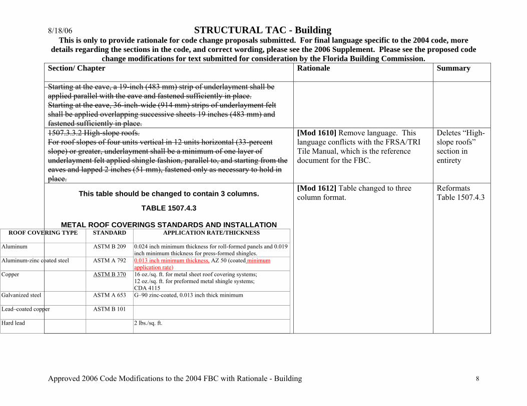
Starting at the eave, a 19-inch (483 mm) strip of underlayment shall be applied parallel with the eave and fastened sufficiently in place. Starting at the eave, 36-inch-wide (914 mm) strips of underlayment felt shall be applied overlapping successive sheets 19 inches (483 mm) and fastened sufficiently in place. 1507.3.3.2 High-slope roofs. For roof slopes of four units vertical in 12 units horizontal (33-percent slope) or greater, underlayment shall be a minimum of one layer of underlayment felt applied shingle fashion, parallel to, and starting from the eaves and lapped 2 inches (51 mm), fastened only as necessary to hold in place.
[Mod 1610] Remove language. This language conflicts with the FRSA/TRI Tile Manual, which is the reference document for the FBC.
Deletes “High-slope roofs” section in entirety
This table should be changed to contain 3 columns.
TABLE 1507.4.3
METAL ROOF COVERINGS STANDARDS AND INSTALLATION ROOF COVERING TYPE
STANDARD APPLICATION RATE/THICKNESS
Aluminum ASTM B 209 0.024 inch minimum thickness for roll-formed panels and 0.019 inch minimum thickness for press-formed shingles.
Aluminum-zinc coated steel
ASTM A 792 0.013 inch minimum thickness, AZ 50 (coated minimum application rate)
Copper ASTM B 370 16 oz./sq. ft. for metal sheet roof covering systems; 12 oz./sq. ft. for preformed metal shingle systems; CDA 4115
Galvanized steel
ASTM A 653 G–90 zinc-coated, 0.013 inch thick minimum
Lead–coated copper
ASTM B 101
Hard lead
2 lbs./sq. ft.
[Mod 1612] Table changed to three column format.
Reformats Table 1507.4.3
8/18/06 STRUCTURAL TAC - Building This is only to provide rationale for code change proposals submitted. For final language specific to the 2004 code, more
details regarding the sections in the code, and correct wording, please see the 2006 Supplement. Please see the proposed code change modifications for text submitted for consideration by the Florida Building Commission.
Approved 2006 Code Modifications to the 2004 FBC with Rationale - Building 9
Section/ Chapter
Rationale Summary
Soft lead
3 lbs./sq. ft.
Prepainted steel
ASTM A 755
Terne (tin) and terne-coated stainless
Terne coating of 40 lbs. per double base box, field painted where applicable in accordance with manufacturer’s installation instructions.
For SI: 1 ounce per square foot = 0.0026 kg/m2,
1 pound per square foot = 4.882 kg/m2, 1 inch = 25.4 mm, 1 pound = 0.454 kg.
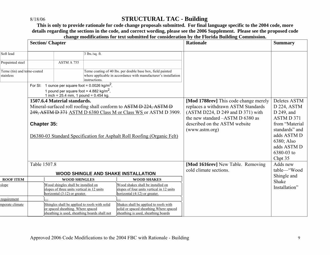
1507.6.4 Material standards. Mineral-surfaced roll roofing shall conform to ASTM D 224, ASTM D 249, ASTM D 371 ASTM D 6380 Class M or Class WS or ASTM D 3909.
Chapter 35:
D6380-03 Standard Specification for Asphalt Roll Roofing (Organic Felt)
[Mod 1788rev] This code change merely replaces a withdrawn ASTM Standards (ASTM D224, D 249 and D 371) with the new standard –ASTM D 6380 as described on the ASTM website (www.astm.org)
Deletes ASTM D 224, ASTM D 249, and ASTM D 371 from “Material standards” and adds ASTM D 6380; Also adds ASTM D 6380-03 to Chpt 35
Table 1507.8
WOOD SHINGLE AND SHAKE INSTALLATION ROOF ITEM WOOD SHINGLES WOOD SHAKES
slope Wood shingles shall be installed on slopes of three units vertical in 12 units horizontal (3:12) or greater.
Wood shakes shall be installed on slopes of four units vertical in 12 units horizontal (4:12) or greater.
requirement — — mperate climate Shingles shall be applied to roofs with solid
or spaced sheathing. Where spaced sheathing is used, sheathing boards shall not
Shakes shall be applied to roofs with solid or spaced sheathing.Where spaced sheathing is used, sheathing boards
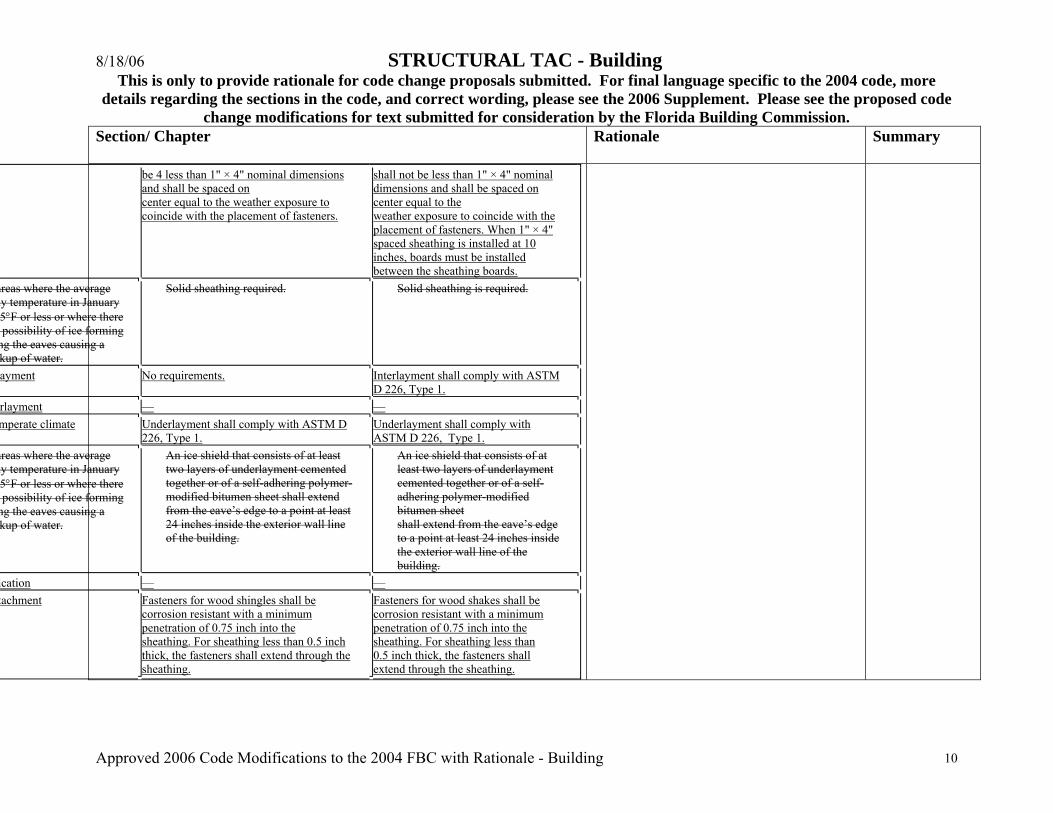
[Mod 1616rev] New Table. Removing cold climate sections.
Adds new table—“Wood Shingle and Shake Installation”
8/18/06 STRUCTURAL TAC - Building This is only to provide rationale for code change proposals submitted. For final language specific to the 2004 code, more
details regarding the sections in the code, and correct wording, please see the 2006 Supplement. Please see the proposed code change modifications for text submitted for consideration by the Florida Building Commission.
Approved 2006 Code Modifications to the 2004 FBC with Rationale - Building 10
Section/ Chapter
Rationale Summary
be 4 less than 1" × 4" nominal dimensions and shall be spaced on center equal to the weather exposure to coincide with the placement of fasteners.
shall not be less than 1" × 4" nominal dimensions and shall be spaced on center equal to the weather exposure to coincide with the placement of fasteners. When 1" × 4" spaced sheathing is installed at 10 inches, boards must be installed between the sheathing boards.
areas where the average ly temperature in January 5°F or less or where there possibility of ice forming
ng the eaves causing a kup of water.
Solid sheathing required. Solid sheathing is required.
ayment No requirements. Interlayment shall comply with ASTM D 226, Type 1.
rlayment — — mperate climate Underlayment shall comply with ASTM D
226, Type 1. Underlayment shall comply with ASTM D 226, Type 1.
areas where the average ly temperature in January 5°F or less or where there possibility of ice forming
ng the eaves causing a kup of water.
An ice shield that consists of at least two layers of underlayment cemented together or of a self-adhering polymer-modified bitumen sheet shall extend from the eave’s edge to a point at least 24 inches inside the exterior wall line of the building.
An ice shield that consists of at least two layers of underlayment cemented together or of a self-adhering polymer-modified bitumen sheet shall extend from the eave’s edge to a point at least 24 inches inside the exterior wall line of the building.
ication — — tachment Fasteners for wood shingles shall be
corrosion resistant with a minimum penetration of 0.75 inch into the sheathing. For sheathing less than 0.5 inch thick, the fasteners shall extend through the sheathing.
Fasteners for wood shakes shall be corrosion resistant with a minimum penetration of 0.75 inch into the sheathing. For sheathing less than 0.5 inch thick, the fasteners shall extend through the sheathing.
8/18/06 STRUCTURAL TAC - Building This is only to provide rationale for code change proposals submitted. For final language specific to the 2004 code, more
details regarding the sections in the code, and correct wording, please see the 2006 Supplement. Please see the proposed code change modifications for text submitted for consideration by the Florida Building Commission.
Approved 2006 Code Modifications to the 2004 FBC with Rationale - Building 11
Section/ Chapter
Rationale Summary
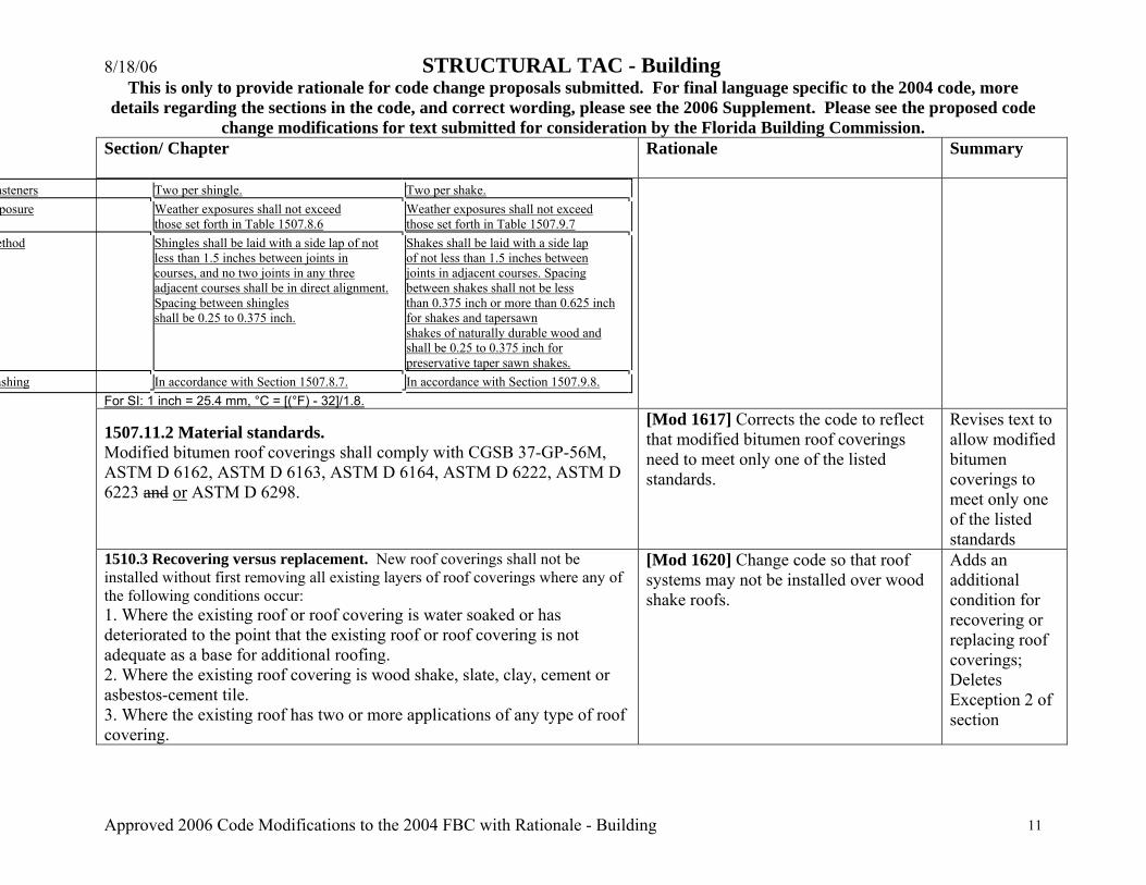
asteners Two per shingle. Two per shake. posure Weather exposures shall not exceed
those set forth in Table 1507.8.6 Weather exposures shall not exceed those set forth in Table 1507.9.7
ethod Shingles shall be laid with a side lap of not less than 1.5 inches between joints in courses, and no two joints in any three adjacent courses shall be in direct alignment. Spacing between shingles shall be 0.25 to 0.375 inch.
Shakes shall be laid with a side lap of not less than 1.5 inches between joints in adjacent courses. Spacing between shakes shall not be less than 0.375 inch or more than 0.625 inch for shakes and tapersawn shakes of naturally durable wood and shall be 0.25 to 0.375 inch for preservative taper sawn shakes.
ashing In accordance with Section 1507.8.7. In accordance with Section 1507.9.8. For SI: 1 inch = 25.4 mm, °C = [(°F) - 32]/1.8.
1507.11.2 Material standards. Modified bitumen roof coverings shall comply with CGSB 37-GP-56M, ASTM D 6162, ASTM D 6163, ASTM D 6164, ASTM D 6222, ASTM D 6223 and or ASTM D 6298.
[Mod 1617] Corrects the code to reflect that modified bitumen roof coverings need to meet only one of the listed standards.
Revises text to allow modified bitumen coverings to meet only one of the listed standards
1510.3 Recovering versus replacement. New roof coverings shall not be installed without first removing all existing layers of roof coverings where any of the following conditions occur: 1. Where the existing roof or roof covering is water soaked or has deteriorated to the point that the existing roof or roof covering is not adequate as a base for additional roofing. 2. Where the existing roof covering is wood shake, slate, clay, cement or asbestos-cement tile. 3. Where the existing roof has two or more applications of any type of roof covering.
[Mod 1620] Change code so that roof systems may not be installed over wood shake roofs.
Adds an additional condition for recovering or replacing roof coverings; Deletes Exception 2 of section
8/18/06 STRUCTURAL TAC - Building This is only to provide rationale for code change proposals submitted. For final language specific to the 2004 code, more
details regarding the sections in the code, and correct wording, please see the 2006 Supplement. Please see the proposed code change modifications for text submitted for consideration by the Florida Building Commission.
Approved 2006 Code Modifications to the 2004 FBC with Rationale - Building 12
Section/ Chapter
Rationale Summary
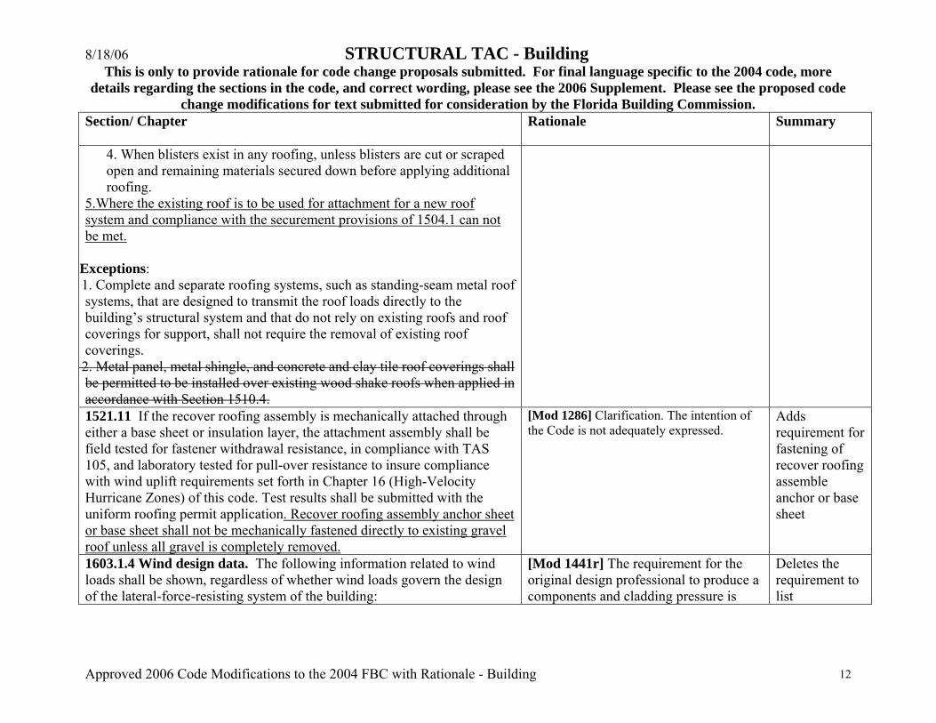
4. When blisters exist in any roofing, unless blisters are cut or scraped open and remaining materials secured down before applying additional roofing.
5.Where the existing roof is to be used for attachment for a new roof system and compliance with the securement provisions of 1504.1 can not be met.
xExceptions: 1. Complete and separate roofing systems, such as standing-seam metal roof systems, that are designed to transmit the roof loads directly to the building’s structural system and that do not rely on existing roofs and roof coverings for support, shall not require the removal of existing roof coverings. 2. Metal panel, metal shingle, and concrete and clay tile roof coverings shall be permitted to be installed over existing wood shake roofs when applied in accordance with Section 1510.4. 1521.11 If the recover roofing assembly is mechanically attached through either a base sheet or insulation layer, the attachment assembly shall be field tested for fastener withdrawal resistance, in compliance with TAS 105, and laboratory tested for pull-over resistance to insure compliance with wind uplift requirements set forth in Chapter 16 (High-Velocity Hurricane Zones) of this code. Test results shall be submitted with the uniform roofing permit application. Recover roofing assembly anchor sheet or base sheet shall not be mechanically fastened directly to existing gravel roof unless all gravel is completely removed.
[Mod 1286] Clarification. The intention of the Code is not adequately expressed.
Adds requirement for fastening of recover roofing assemble anchor or base sheet
1603.1.4 Wind design data. The following information related to wind loads shall be shown, regardless of whether wind loads govern the design of the lateral-force-resisting system of the building:
[Mod 1441r] The requirement for the original design professional to produce a components and cladding pressure is
Deletes the requirement to list
8/18/06 STRUCTURAL TAC - Building This is only to provide rationale for code change proposals submitted. For final language specific to the 2004 code, more
details regarding the sections in the code, and correct wording, please see the 2006 Supplement. Please see the proposed code change modifications for text submitted for consideration by the Florida Building Commission.
Approved 2006 Code Modifications to the 2004 FBC with Rationale - Building 13
Section/ Chapter
Rationale Summary
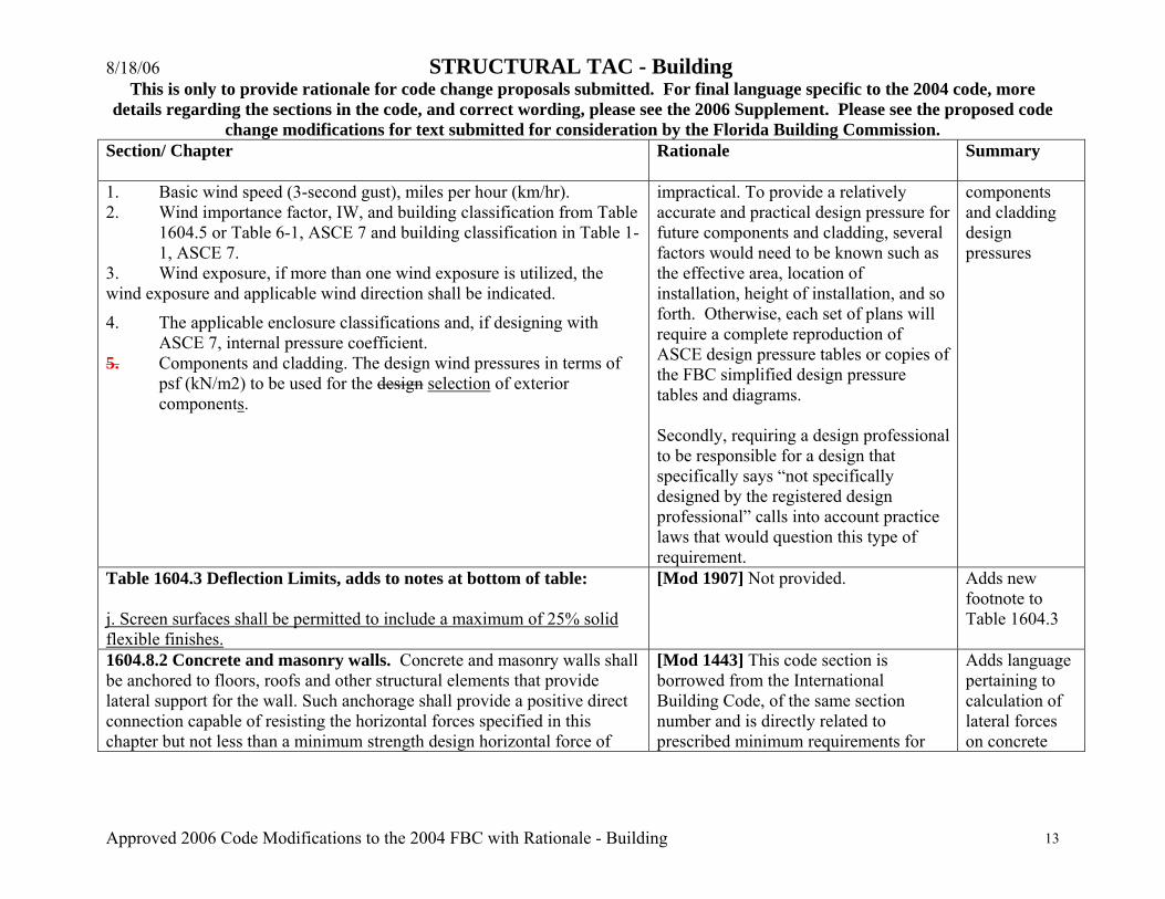
1. Basic wind speed (3-second gust), miles per hour (km/hr). 2. Wind importance factor, IW, and building classification from Table
1604.5 or Table 6-1, ASCE 7 and building classification in Table 1-1, ASCE 7.
3. Wind exposure, if more than one wind exposure is utilized, the wind exposure and applicable wind direction shall be indicated.
4. The applicable enclosure classifications and, if designing with ASCE 7, internal pressure coefficient.
5. Components and cladding. The design wind pressures in terms of psf (kN/m2) to be used for the design selection of exterior components.
impractical. To provide a relatively accurate and practical design pressure for future components and cladding, several factors would need to be known such as the effective area, location of installation, height of installation, and so forth. Otherwise, each set of plans will require a complete reproduction of ASCE design pressure tables or copies of the FBC simplified design pressure tables and diagrams. Secondly, requiring a design professional to be responsible for a design that specifically says “not specifically designed by the registered design professional” calls into account practice laws that would question this type of requirement.
components and cladding design pressures
Table 1604.3 Deflection Limits, adds to notes at bottom of table: j. Screen surfaces shall be permitted to include a maximum of 25% solid flexible finishes.
[Mod 1907] Not provided. Adds new footnote to Table 1604.3
1604.8.2 Concrete and masonry walls. Concrete and masonry walls shall be anchored to floors, roofs and other structural elements that provide lateral support for the wall. Such anchorage shall provide a positive direct connection capable of resisting the horizontal forces specified in this chapter but not less than a minimum strength design horizontal force of
[Mod 1443] This code section is borrowed from the International Building Code, of the same section number and is directly related to prescribed minimum requirements for
Adds language pertaining to calculation of lateral forces on concrete

8/18/06 STRUCTURAL TAC - Building This is only to provide rationale for code change proposals submitted. For final language specific to the 2004 code, more
details regarding the sections in the code, and correct wording, please see the 2006 Supplement. Please see the proposed code change modifications for text submitted for consideration by the Florida Building Commission.
Approved 2006 Code Modifications to the 2004 FBC with Rationale - Building 14
Section/ Chapter
Rationale Summary
280 plf (4.10 kN/m) of wall, unless the lateral force has otherwise been calculated by the Engineer of Record. Walls shall be designed to resist bending between anchors where the anchor spacing exceeds 4 feet (1219 mm). Required anchors in masonry walls of hollow units or cavity walls shall be embedded in a reinforced grouted structural element of the wall. See Sections 1609.6.5 for wind design requirements.
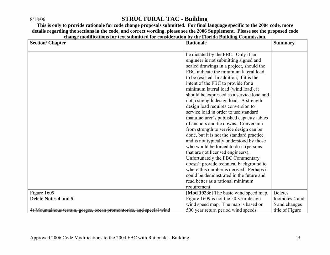
buildings situated in an earthquake zone. In examining the original section in the International Building Code it has been noticed that the words “substituted for ‘E’”, in sentence two of the section is missing from the FBC version. The ‘E’ stands for earthquake. Currently the FBC doesn’t deal with earthquake loads, and ‘E’ isn’t a part of the load cases or combinations. I believe it is important to have a minimum lateral load that walls need to be anchored against, however the code comes across as being arbitrary and causing undue costs in some buildings, where a licensed Engineer is providing certification of the design. If Designers are required to specify anchorage, say from a masonry wall to a pre-engineered roof truss, having the FBC require that the tie-down anchors be sufficient for both uplift and lateral load of 280 pounds-per-foot, could, in some cases require twice as many anchors as would otherwise be necessary. I believe that when a Florida licensed structural engineer is certifying that the design is in conformance with ASCE7 wind code, then an arbitrary lateral load should not
and masonry walls
8/18/06 STRUCTURAL TAC - Building This is only to provide rationale for code change proposals submitted. For final language specific to the 2004 code, more
details regarding the sections in the code, and correct wording, please see the 2006 Supplement. Please see the proposed code change modifications for text submitted for consideration by the Florida Building Commission.
Approved 2006 Code Modifications to the 2004 FBC with Rationale - Building 15
Section/ Chapter
Rationale Summary
be dictated by the FBC. Only if an engineer is not submitting signed and sealed drawings in a project, should the FBC indicate the minimum lateral load to be resisted. In addition, if it is the intent of the FBC to provide for a minimum lateral load (wind load), it should be expressed as a service load and not a strength design load. A strength design load requires conversion to service load in order to use standard manufacturer’s published capacity tables of anchors and tie downs. Conversion from strength to service design can be done, but it is not the standard practice and is not typically understood by those who would be forced to do it (persons that are not licensed engineers). Unfortunately the FBC Commentary doesn’t provide technical background to where this number is derived. Perhaps it could be demonstrated in the future and read better as a rational minimum requirement.
Figure 1609 Delete Notes 4 and 5. 4) Mountainous terrain, gorges, ocean promontories, and special wind
[Mod 1923r] The basic wind speed map, Figure 1609 is not the 50-year design wind speed map. The map is based on 500 year return period wind speeds
Deletes footnotes 4 and 5 and changes title of Figure
8/18/06 STRUCTURAL TAC - Building This is only to provide rationale for code change proposals submitted. For final language specific to the 2004 code, more
details regarding the sections in the code, and correct wording, please see the 2006 Supplement. Please see the proposed code change modifications for text submitted for consideration by the Florida Building Commission.
Approved 2006 Code Modifications to the 2004 FBC with Rationale - Building 16
Section/ Chapter
Rationale Summary
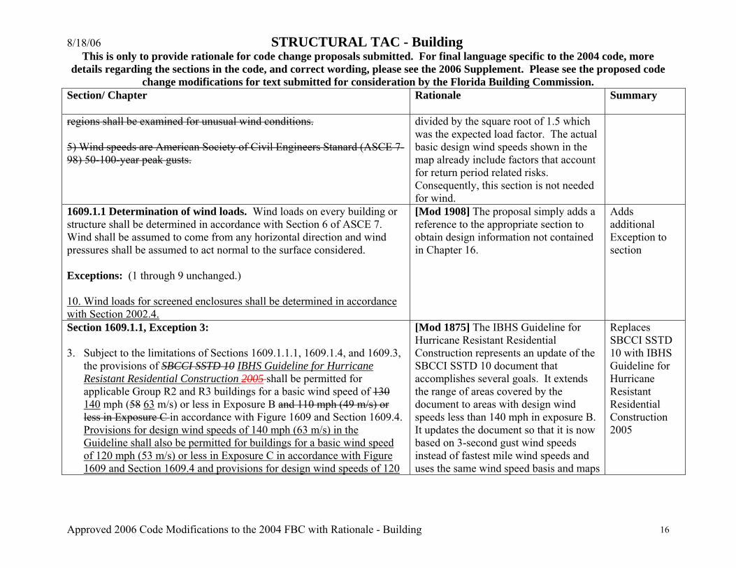
regions shall be examined for unusual wind conditions. 5) Wind speeds are American Society of Civil Engineers Stanard (ASCE 7-98) 50-100-year peak gusts.
divided by the square root of 1.5 which was the expected load factor. The actual basic design wind speeds shown in the map already include factors that account for return period related risks. Consequently, this section is not needed for wind.
1609.1.1 Determination of wind loads. Wind loads on every building or structure shall be determined in accordance with Section 6 of ASCE 7. Wind shall be assumed to come from any horizontal direction and wind pressures shall be assumed to act normal to the surface considered. Exceptions: (1 through 9 unchanged.) 10. Wind loads for screened enclosures shall be determined in accordance with Section 2002.4.
[Mod 1908] The proposal simply adds a reference to the appropriate section to obtain design information not contained in Chapter 16.
Adds additional Exception to section
Section 1609.1.1, Exception 3: 3. Subject to the limitations of Sections 1609.1.1.1, 1609.1.4, and 1609.3,
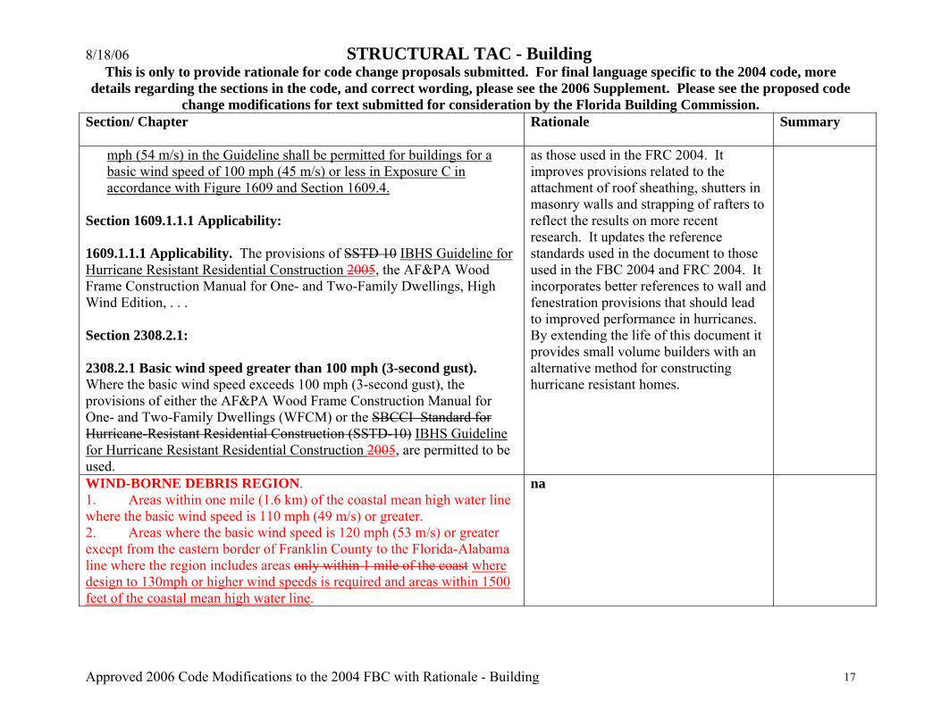
the provisions of SBCCI SSTD 10 IBHS Guideline for Hurricane Resistant Residential Construction 2005 shall be permitted for applicable Group R2 and R3 buildings for a basic wind speed of 130 140 mph (58 63 m/s) or less in Exposure B and 110 mph (49 m/s) or less in Exposure C in accordance with Figure 1609 and Section 1609.4. Provisions for design wind speeds of 140 mph (63 m/s) in the Guideline shall also be permitted for buildings for a basic wind speed of 120 mph (53 m/s) or less in Exposure C in accordance with Figure 1609 and Section 1609.4 and provisions for design wind speeds of 120
[Mod 1875] The IBHS Guideline for Hurricane Resistant Residential Construction represents an update of the SBCCI SSTD 10 document that accomplishes several goals. It extends the range of areas covered by the document to areas with design wind speeds less than 140 mph in exposure B. It updates the document so that it is now based on 3-second gust wind speeds instead of fastest mile wind speeds and uses the same wind speed basis and maps
Replaces SBCCI SSTD 10 with IBHS Guideline for Hurricane Resistant Residential Construction 2005
8/18/06 STRUCTURAL TAC - Building This is only to provide rationale for code change proposals submitted. For final language specific to the 2004 code, more
details regarding the sections in the code, and correct wording, please see the 2006 Supplement. Please see the proposed code change modifications for text submitted for consideration by the Florida Building Commission.
Approved 2006 Code Modifications to the 2004 FBC with Rationale - Building 17
Section/ Chapter
Rationale Summary
mph (54 m/s) in the Guideline shall be permitted for buildings for a basic wind speed of 100 mph (45 m/s) or less in Exposure C in accordance with Figure 1609 and Section 1609.4.
Section 1609.1.1.1 Applicability: 1609.1.1.1 Applicability. The provisions of SSTD 10 IBHS Guideline for Hurricane Resistant Residential Construction 2005, the AF&PA Wood Frame Construction Manual for One- and Two-Family Dwellings, High Wind Edition, . . . Section 2308.2.1: 2308.2.1 Basic wind speed greater than 100 mph (3-second gust). Where the basic wind speed exceeds 100 mph (3-second gust), the provisions of either the AF&PA Wood Frame Construction Manual for One- and Two-Family Dwellings (WFCM) or the SBCCI Standard for Hurricane-Resistant Residential Construction (SSTD-10) IBHS Guideline for Hurricane Resistant Residential Construction 2005, are permitted to be used.
as those used in the FRC 2004. It improves provisions related to the attachment of roof sheathing, shutters in masonry walls and strapping of rafters to reflect the results on more recent research. It updates the reference standards used in the document to those used in the FBC 2004 and FRC 2004. It incorporates better references to wall and fenestration provisions that should lead to improved performance in hurricanes. By extending the life of this document it provides small volume builders with an alternative method for constructing hurricane resistant homes.
WIND-BORNE DEBRIS REGION. 1. Areas within one mile (1.6 km) of the coastal mean high water line where the basic wind speed is 110 mph (49 m/s) or greater. 2. Areas where the basic wind speed is 120 mph (53 m/s) or greater except from the eastern border of Franklin County to the Florida-Alabama line where the region includes areas only within 1 mile of the coast where design to 130mph or higher wind speeds is required and areas within 1500 feet of the coastal mean high water line.
na
8/18/06 STRUCTURAL TAC - Building This is only to provide rationale for code change proposals submitted. For final language specific to the 2004 code, more
details regarding the sections in the code, and correct wording, please see the 2006 Supplement. Please see the proposed code change modifications for text submitted for consideration by the Florida Building Commission.
Approved 2006 Code Modifications to the 2004 FBC with Rationale - Building 18
Section/ Chapter
Rationale Summary
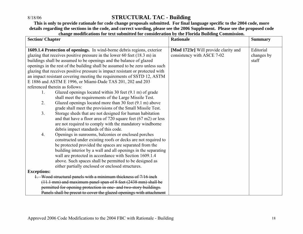
1609.1.4 Protection of openings. In wind-borne debris regions, exterior glazing that receives positive pressure in the lower 60 feet (18.3 m) in buildings shall be assumed to be openings and the balance of glazed openings in the rest of the building shall be assumed to be zero unless such glazing that receives positive pressure is impact resistant or protected with an impact resistant covering meeting the requirements of SSTD 12, ASTM E 1886 and ASTM E 1996, or Miami-Dade TAS 201, 202 and 203 referenced therein as follows:
1. Glazed openings located within 30 feet (9.1 m) of grade shall meet the requirements of the Large Missile Test.
2. Glazed openings located more than 30 feet (9.1 m) above grade shall meet the provisions of the Small Missile Test.
3. Storage sheds that are not designed for human habitation and that have a floor area of 720 square feet (67 m2) or less are not required to comply with the mandatory windborne debris impact standards of this code.
4. Openings in sunrooms, balconies or enclosed porches constructed under existing roofs or decks are not required to be protected provided the spaces are separated from the building interior by a wall and all openings in the separating wall are protected in accordance with Section 1609.1.4 above. Such spaces shall be permitted to be designed as either partially enclosed or enclosed structures.
Exceptions: 1. Wood structural panels with a minimum thickness of 7/16 inch
(11.1 mm) and maximum panel span of 8 feet (2438 mm) shall be permitted for opening protection in one- and two-story buildings. Panels shall be precut to cover the glazed openings with attachment
[Mod 1723r] Will provide clarity and consistency with ASCE 7-02
Editorial changes by staff

8/18/06 STRUCTURAL TAC - Building This is only to provide rationale for code change proposals submitted. For final language specific to the 2004 code, more
details regarding the sections in the code, and correct wording, please see the 2006 Supplement. Please see the proposed code change modifications for text submitted for consideration by the Florida Building Commission.
Approved 2006 Code Modifications to the 2004 FBC with Rationale - Building 19
Section/ Chapter
Rationale Summary
hardware provided. Attachments shall be designed to resist the components and cladding loads determined in accordance with the provisions of Section 1609.6.5. Attachment in accordance with Table 1609.1.4 is permitted for buildings with a mean roof height of 33 feet (10 058 mm) or less where wind speeds do not exceed 130 mph (57.2 m/s).
1. Wood structural panels with a minimum thickness of 7/16 inch
(11.1 mm) and maximum panel span of 8 feet (2438 mm) shall be permitted for opening protection in one- and two-story buildings. Panels shall be precut to cover the glazed openings with attachment hardware provided. Attachments shall be designed to resist the components and cladding loads determined in accordance with the provisions of Section 1609.6.1.2. Attachment in accordance with Table 1609.1.4 is permitted for buildings with a mean roof height of 33 feet (10 058 mm) or less where wind speeds do not exceed 130 mph (57.2 m/s).
2. Buildings in Category I as defined in Table 1604.5, including
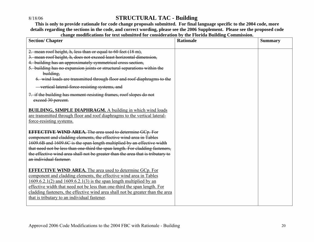
production greenhouses as defined in Section 1602. 1609.2 Definitions. Revise the following definitions as stated below. Remaining definitions unchanged BUILDING, SIMPLE DIAPHRAGM. A building which complies with all of the following conditions: 1. enclosed building,
8/18/06 STRUCTURAL TAC - Building This is only to provide rationale for code change proposals submitted. For final language specific to the 2004 code, more
details regarding the sections in the code, and correct wording, please see the 2006 Supplement. Please see the proposed code change modifications for text submitted for consideration by the Florida Building Commission.
Approved 2006 Code Modifications to the 2004 FBC with Rationale - Building 20
Section/ Chapter
Rationale Summary
2. mean roof height, h, less than or equal to 60 feet (18 m), 3. mean roof height, h, does not exceed least horizontal dimension, 4. building has an approximately symmetrical cross section, 5. building has no expansion joints or structural separations within the
building, 6. wind loads are transmitted through floor and roof diaphragms to the
vertical lateral-force-resisting systems, and
7. if the building has moment-resisting frames, roof slopes do not exceed 30 percent. BUILDING, SIMPLE DIAPHRAGM. A building in which wind loads are transmitted through floor and roof diaphragms to the vertical lateral-force-resisting systems. EFFECTIVE WIND AREA. The area used to determine GCp. For component and cladding elements, the effective wind area in Tables 1609.6B and 1609.6C is the span length multiplied by an effective width that need not be less than one-third the span length. For cladding fasteners, the effective wind area shall not be greater than the area that is tributary to an individual fastener. EFFECTIVE WIND AREA. The area used to determine GCp. For component and cladding elements, the effective wind area in Tables 1609.6.2.1(2) and 1609.6.2.1(3) is the span length multiplied by an effective width that need not be less than one-third the span length. For cladding fasteners, the effective wind area shall not be greater than the area that is tributary to an individual fastener.
8/18/06 STRUCTURAL TAC - Building This is only to provide rationale for code change proposals submitted. For final language specific to the 2004 code, more
details regarding the sections in the code, and correct wording, please see the 2006 Supplement. Please see the proposed code change modifications for text submitted for consideration by the Florida Building Commission.
Approved 2006 Code Modifications to the 2004 FBC with Rationale - Building 21
Section/ Chapter
Rationale Summary
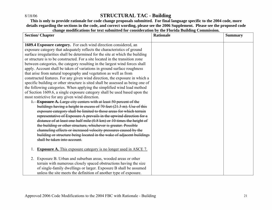
1609.4 Exposure category. For each wind direction considered, an exposure category that adequately reflects the characteristics of ground surface irregularities shall be determined for the site at which the building or structure is to be constructed. For a site located in the transition zone between categories, the category resulting in the largest wind forces shall apply. Account shall be taken of variations in ground surface roughness that arise from natural topography and vegetation as well as from constructed features. For any given wind direction, the exposure in which a specific building or other structure is sited shall be assessed as being one of the following categories. When applying the simplified wind load method of Section 1609.6, a single exposure category shall be used based upon the most restrictive for any given wind direction.
1. Exposure A. Large city centers with at least 50 percent of the buildings having a height in excess of 70 feet (21.3 m). Use of this exposure category shall be limited to those areas for which terrain representative of Exposure A prevails in the upwind direction for a distance of at least one-half mile (0.8 km) or 10 times the height of the building or other structure, whichever is greater. Possible channeling effects or increased velocity pressures caused by the building or structure being located in the wake of adjacent buildings shall be taken into account.
1. Exposure A. This exposure category is no longer used in ASCE 7. 2. Exposure B. Urban and suburban areas, wooded areas or other
terrain with numerous closely spaced obstructions having the size of single-family dwellings or larger. Exposure B shall be assumed unless the site meets the definition of another type of exposure.
8/18/06 STRUCTURAL TAC - Building This is only to provide rationale for code change proposals submitted. For final language specific to the 2004 code, more
details regarding the sections in the code, and correct wording, please see the 2006 Supplement. Please see the proposed code change modifications for text submitted for consideration by the Florida Building Commission.
Approved 2006 Code Modifications to the 2004 FBC with Rationale - Building 22
Section/ Chapter
Rationale Summary
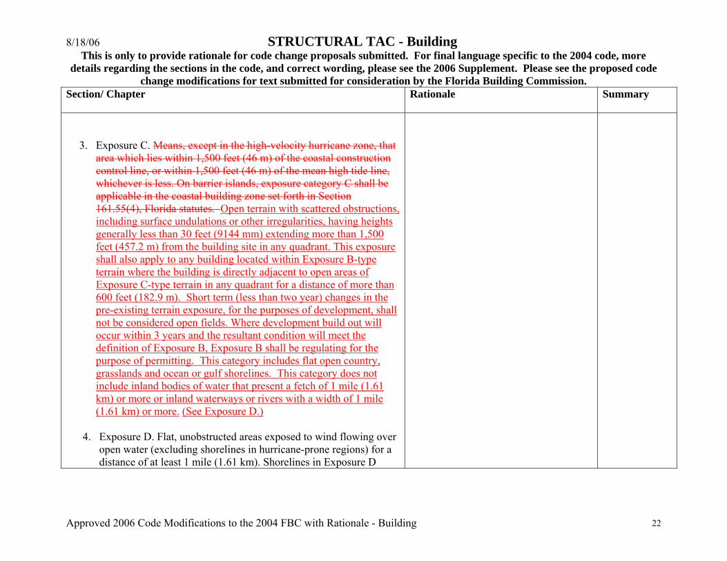
3. Exposure C. Means, except in the high-velocity hurricane zone, that area which lies within 1,500 feet (46 m) of the coastal construction control line, or within 1,500 feet (46 m) of the mean high tide line, whichever is less. On barrier islands, exposure category C shall be applicable in the coastal building zone set forth in Section 161.55(4), Florida statutes. Open terrain with scattered obstructions, including surface undulations or other irregularities, having heights generally less than 30 feet (9144 mm) extending more than 1,500 feet (457.2 m) from the building site in any quadrant. This exposure shall also apply to any building located within Exposure B-type terrain where the building is directly adjacent to open areas of Exposure C-type terrain in any quadrant for a distance of more than 600 feet (182.9 m). Short term (less than two year) changes in the pre-existing terrain exposure, for the purposes of development, shall not be considered open fields. Where development build out will occur within 3 years and the resultant condition will meet the definition of Exposure B, Exposure B shall be regulating for the purpose of permitting. This category includes flat open country, grasslands and ocean or gulf shorelines. This category does not include inland bodies of water that present a fetch of 1 mile (1.61 km) or more or inland waterways or rivers with a width of 1 mile (1.61 km) or more. (See Exposure D.)
4. Exposure D. Flat, unobstructed areas exposed to wind flowing over open water (excluding shorelines in hurricane-prone regions) for a distance of at least 1 mile (1.61 km). Shorelines in Exposure D

8/18/06 STRUCTURAL TAC - Building This is only to provide rationale for code change proposals submitted. For final language specific to the 2004 code, more
details regarding the sections in the code, and correct wording, please see the 2006 Supplement. Please see the proposed code change modifications for text submitted for consideration by the Florida Building Commission.
Approved 2006 Code Modifications to the 2004 FBC with Rationale - Building 23
Section/ Chapter
Rationale Summary
include inland waterways, the Great Lakes and coastal areas of California, Oregon, Washington and Alaska. This exposure shall apply only to those buildings and other structures exposed to the wind coming from over the water. Exposure D extends inland from the shoreline a distance of 1,500 feet (460 m) or 10 times the height of the building or structure, whichever is greater.
1609.6 Simplified wind load method provisions for low-rise buildings. 1609.6.1 Scope. Procedures in Section 1609.6 shall be used for determining and applying wind pressures in the design of simple diaphragm buildings with flat, hipped and gable-shaped roofs having a mean roof height not exceeding the least horizontal dimension of the building or 60 feet (18.3 m), whichever is less. The provisions of Section 1609.6 shall not be used if any of the following conditions exist: 1. Buildings on which exterior glazing is considered to be openings in
accordance with Section 1609.1.4. 2. Buildings sited on the upper half of an isolated hill or escarpment
meeting all the following conditions: 2.1 The hill or escarpment is 60 feet (18.3 m) or higher if located
in exposure B or 30 feet (9.1 m) or higher if located in Exposure C.
2.2 The maximum average slope of the hill exceeds 10 percent. 2.3 The hill or escarpment is unobstructed upwind by other such
topographic features for a distance from the high point of 50
8/18/06 STRUCTURAL TAC - Building This is only to provide rationale for code change proposals submitted. For final language specific to the 2004 code, more
details regarding the sections in the code, and correct wording, please see the 2006 Supplement. Please see the proposed code change modifications for text submitted for consideration by the Florida Building Commission.
Approved 2006 Code Modifications to the 2004 FBC with Rationale - Building 24
Section/ Chapter
Rationale Summary
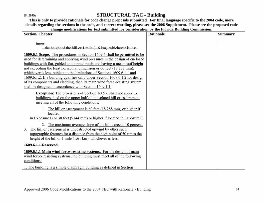
times the height of the hill or 1 mile (1.6 km), whichever is less.
1609.6.1 Scope. The procedures in Section 1609.6 shall be permitted to be used for determining and applying wind pressures in the design of enclosed buildings with flat, gabled and hipped roofs and having a mean roof height not exceeding the least horizontal dimension or 60 feet (18 288 mm), whichever is less, subject to the limitations of Sections 1609.6.1.1 and 1609.6.1.2. If a building qualifies only under Section 1609.6.1.2 for design of its components and cladding, then its main wind force-resisting system shall be designed in accordance with Section 1609.1.1.
Exception: The provisions of Section 1609.6 shall not apply to buildings sited on the upper half of an isolated hill or escarpment meeting all of the following conditions:
1. The hill or escarpment is 60 feet (18 288 mm) or higher if located
in Exposure B or 30 feet (9144 mm) or higher if located in Exposure C.
2. The maximum average slope of the hill exceeds 10 percent. 3. The hill or escarpment is unobstructed upwind by other such
topographic features for a distance from the high point of 50 times the height of the hill or 1 mile (1.61 km), whichever is less.
1609.6.1.1 Reserved. 1609.6.1.1 Main wind force-resisting systems. For the design of main wind force- resisting systems, the building must meet all of the following conditions:
1. The building is a simple diaphragm building as defined in Section
8/18/06 STRUCTURAL TAC - Building This is only to provide rationale for code change proposals submitted. For final language specific to the 2004 code, more
details regarding the sections in the code, and correct wording, please see the 2006 Supplement. Please see the proposed code change modifications for text submitted for consideration by the Florida Building Commission.
Approved 2006 Code Modifications to the 2004 FBC with Rationale - Building 25
Section/ Chapter
Rationale Summary
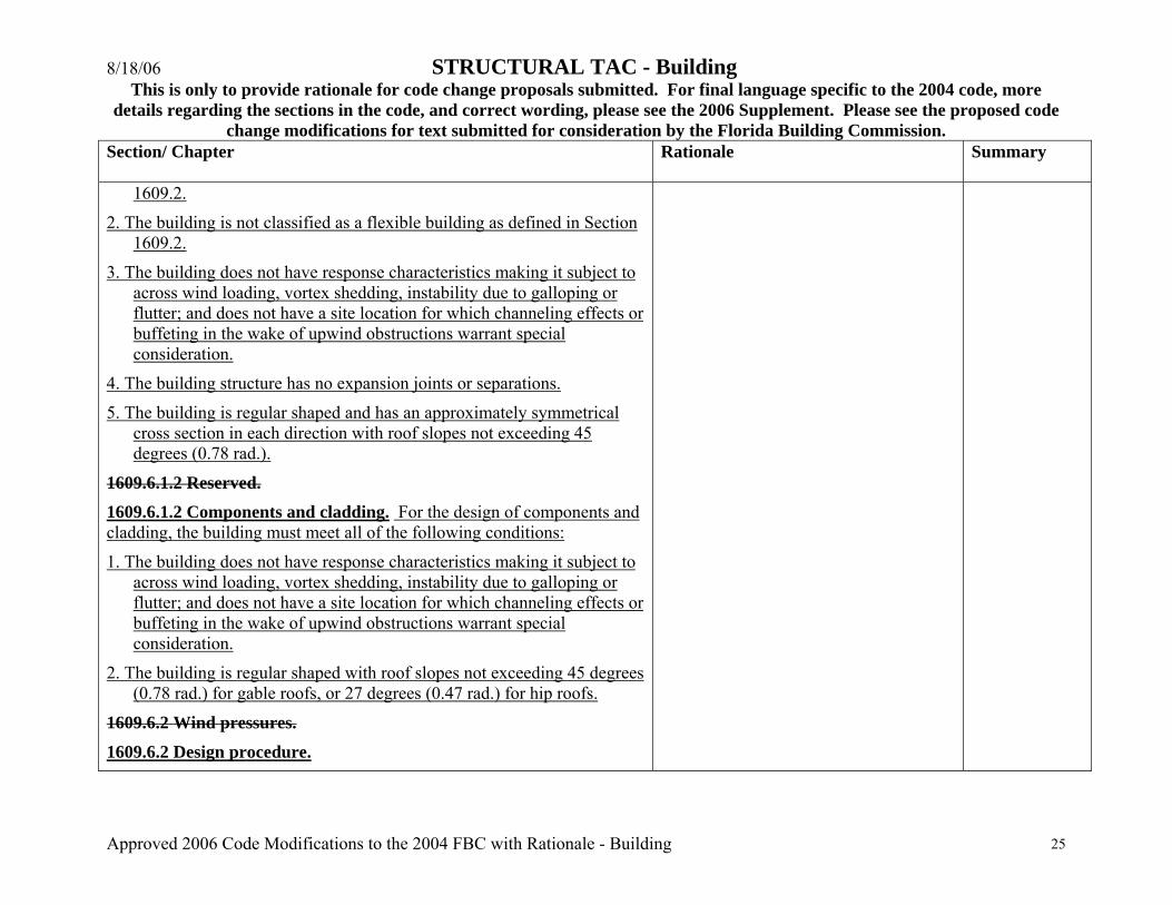
1609.2.
2. The building is not classified as a flexible building as defined in Section 1609.2.
3. The building does not have response characteristics making it subject to across wind loading, vortex shedding, instability due to galloping or flutter; and does not have a site location for which channeling effects or buffeting in the wake of upwind obstructions warrant special consideration.
4. The building structure has no expansion joints or separations.
5. The building is regular shaped and has an approximately symmetrical cross section in each direction with roof slopes not exceeding 45 degrees (0.78 rad.).
1609.6.1.2 Reserved. 1609.6.1.2 Components and cladding. For the design of components and cladding, the building must meet all of the following conditions:
1. The building does not have response characteristics making it subject to across wind loading, vortex shedding, instability due to galloping or flutter; and does not have a site location for which channeling effects or buffeting in the wake of upwind obstructions warrant special consideration.
2. The building is regular shaped with roof slopes not exceeding 45 degrees (0.78 rad.) for gable roofs, or 27 degrees (0.47 rad.) for hip roofs.
1609.6.2 Wind pressures.
1609.6.2 Design procedure.
8/18/06 STRUCTURAL TAC - Building This is only to provide rationale for code change proposals submitted. For final language specific to the 2004 code, more
details regarding the sections in the code, and correct wording, please see the 2006 Supplement. Please see the proposed code change modifications for text submitted for consideration by the Florida Building Commission.
Approved 2006 Code Modifications to the 2004 FBC with Rationale - Building 26
Section/ Chapter
Rationale Summary
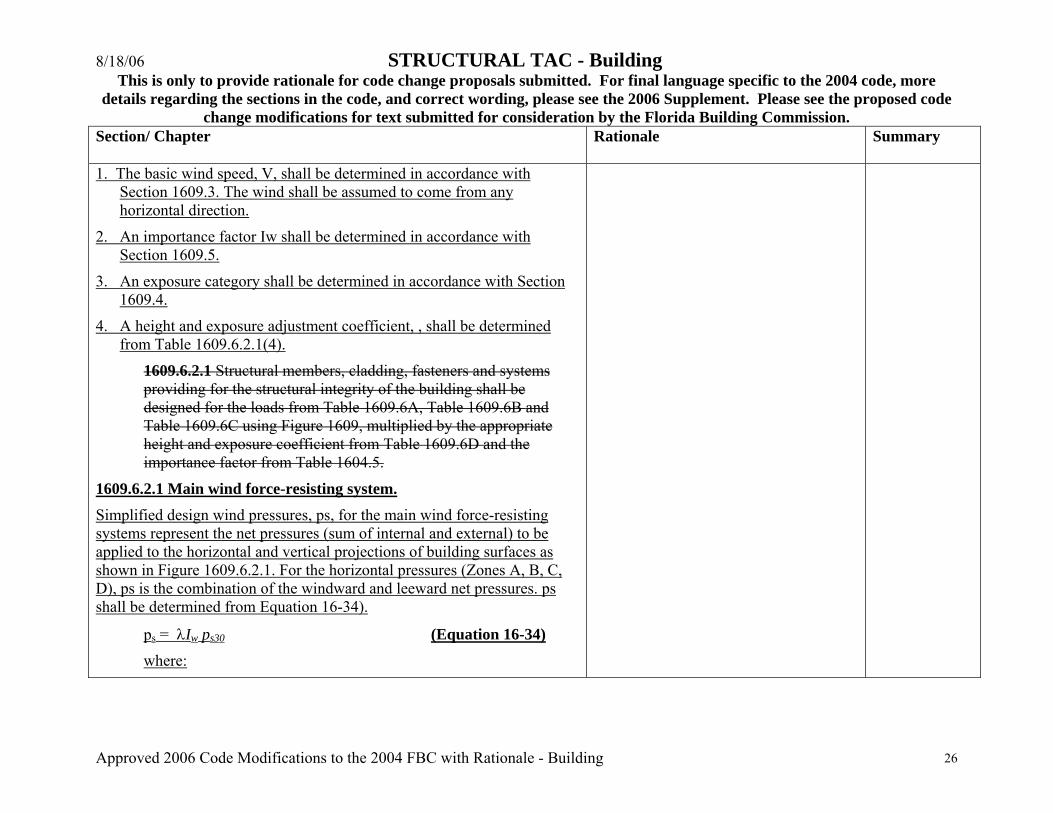
1. The basic wind speed, V, shall be determined in accordance with Section 1609.3. The wind shall be assumed to come from any horizontal direction.
2. An importance factor Iw shall be determined in accordance with Section 1609.5.
3. An exposure category shall be determined in accordance with Section 1609.4.
4. A height and exposure adjustment coefficient, , shall be determined from Table 1609.6.2.1(4).
1609.6.2.1 Structural members, cladding, fasteners and systems providing for the structural integrity of the building shall be designed for the loads from Table 1609.6A, Table 1609.6B and Table 1609.6C using Figure 1609, multiplied by the appropriate height and exposure coefficient from Table 1609.6D and the importance factor from Table 1604.5.
1609.6.2.1 Main wind force-resisting system. Simplified design wind pressures, ps, for the main wind force-resisting systems represent the net pressures (sum of internal and external) to be applied to the horizontal and vertical projections of building surfaces as shown in Figure 1609.6.2.1. For the horizontal pressures (Zones A, B, C, D), ps is the combination of the windward and leeward net pressures. ps shall be determined from Equation 16-34).
ps = λIw ps30 (Equation 16-34)
where:

8/18/06 STRUCTURAL TAC - Building This is only to provide rationale for code change proposals submitted. For final language specific to the 2004 code, more
details regarding the sections in the code, and correct wording, please see the 2006 Supplement. Please see the proposed code change modifications for text submitted for consideration by the Florida Building Commission.
Approved 2006 Code Modifications to the 2004 FBC with Rationale - Building 27
Section/ Chapter
Rationale Summary
λ = Adjustment factor for building height and exposure from Table 1609.6.2.1(4).
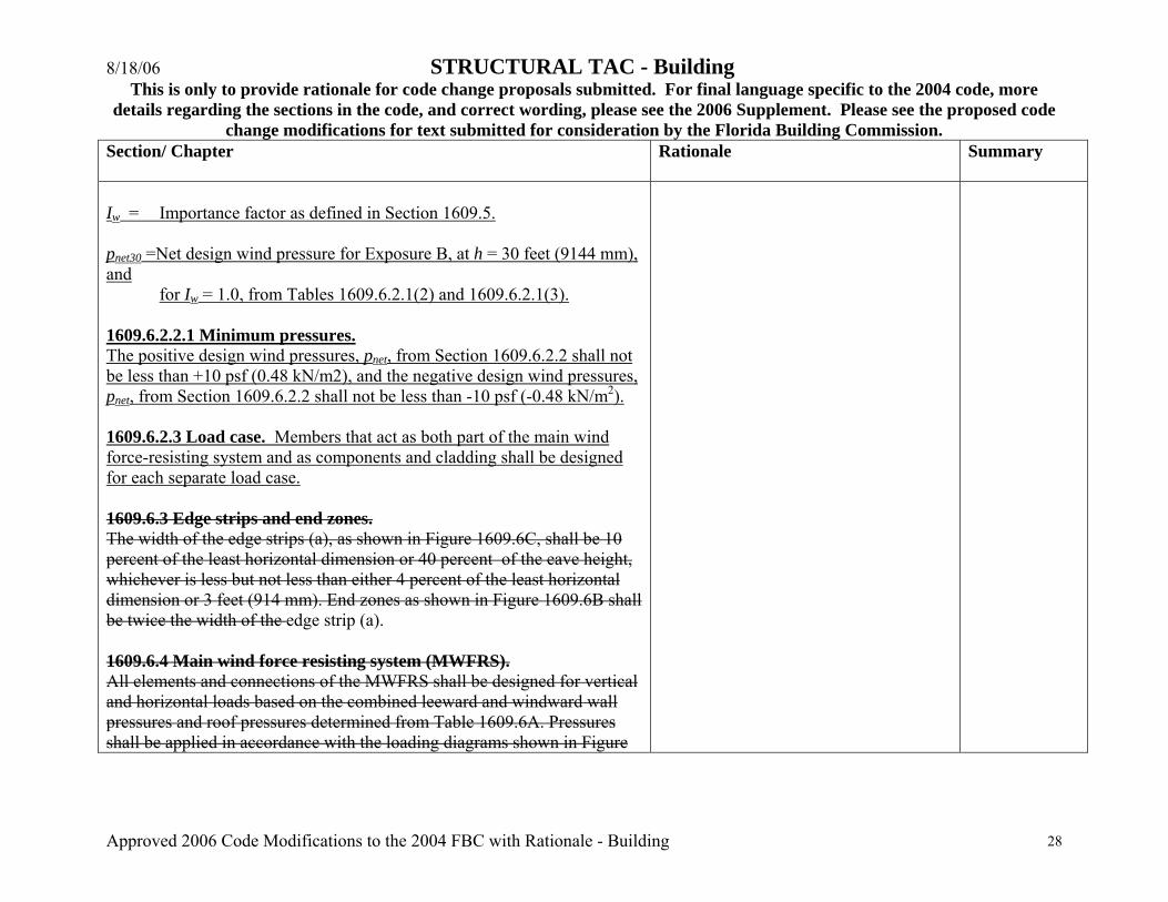
Iw = Importance factor as defined in Section 1609.5
ps30 = Simplified design wind pressure for Exposure B, at h = 30 feet (9144 mm), and for Iw = 1.0, from Table 1609.6.2.1(1).
1609.6.2.1.1 Minimum pressures. The load effects of the design wind pressures from Section 1609.6.2.1 shall not be less than assuming the pressures , ps, for Zones A, B, C and D all equal to +10 psf (0.48 kN/m2), while assuming Zones E, F, G, and H all equal to 0 psf.
1609.6.2.2 Members that act as both part of the main wind-force-resisting system and as components and cladding shall be designed for each separate load case.
1609.6.2.2 Components and cladding. Net design wind pressures, pnet, for the components and cladding of buildings represent the net pressures (sum of internal and external) to be applied normal to each building surface as shown in Figure 1609.6.2.2. The net design wind pressure, pnet, shall be determined from Equation 16-35: pnet = λIw pnet30 (Equation 16-35) where: λ = Adjustment factor for building height and exposure from Table
1609.6.2.1(4).
8/18/06 STRUCTURAL TAC - Building This is only to provide rationale for code change proposals submitted. For final language specific to the 2004 code, more
details regarding the sections in the code, and correct wording, please see the 2006 Supplement. Please see the proposed code change modifications for text submitted for consideration by the Florida Building Commission.
Approved 2006 Code Modifications to the 2004 FBC with Rationale - Building 28
Section/ Chapter
Rationale Summary
Iw = Importance factor as defined in Section 1609.5. pnet30 =Net design wind pressure for Exposure B, at h = 30 feet (9144 mm), and
for Iw = 1.0, from Tables 1609.6.2.1(2) and 1609.6.2.1(3). 1609.6.2.2.1 Minimum pressures. The positive design wind pressures, pnet, from Section 1609.6.2.2 shall not be less than +10 psf (0.48 kN/m2), and the negative design wind pressures, pnet, from Section 1609.6.2.2 shall not be less than -10 psf (-0.48 kN/m2). 1609.6.2.3 Load case. Members that act as both part of the main wind force-resisting system and as components and cladding shall be designed for each separate load case. 1609.6.3 Edge strips and end zones. The width of the edge strips (a), as shown in Figure 1609.6C, shall be 10 percent of the least horizontal dimension or 40 percent of the eave height, whichever is less but not less than either 4 percent of the least horizontal dimension or 3 feet (914 mm). End zones as shown in Figure 1609.6B shall be twice the width of the edge strip (a). 1609.6.4 Main wind force resisting system (MWFRS). All elements and connections of the MWFRS shall be designed for vertical and horizontal loads based on the combined leeward and windward wall pressures and roof pressures determined from Table 1609.6A. Pressures shall be applied in accordance with the loading diagrams shown in Figure
8/18/06 STRUCTURAL TAC - Building This is only to provide rationale for code change proposals submitted. For final language specific to the 2004 code, more
details regarding the sections in the code, and correct wording, please see the 2006 Supplement. Please see the proposed code change modifications for text submitted for consideration by the Florida Building Commission.
Approved 2006 Code Modifications to the 2004 FBC with Rationale - Building 29
Section/ Chapter
Rationale Summary
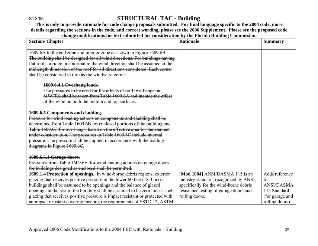
1609.6A to the end zone and interior zone as shown in Figure 1609.6B. The building shall be designed for all wind directions. For buildings having flat roofs, a ridge line normal to the wind direction shall be assumed at the midlength dimension of the roof for all directions considered. Each corner shall be considered in turn as the windward corner.
1609.6.4.1 Overhang loads. The pressures to be used for the effects of roof overhangs on MWFRS shall be taken from Table 1609.6A and include the effect of the wind on both the bottom and top surfaces.
1609.6.5 Components and cladding. Pressure for wind loading actions on components and cladding shall be determined from Table 1609.6B for enclosed portions of the building and Table 1609.6C for overhangs, based on the effective area for the element under consideration. The pressures in Table 1609.6C include internal pressure. The pressure shall be applied in accordance with the loading diagrams in Figure 1609.6C. 1609.6.5.1 Garage doors. Pressures from Table 1609.6E. for wind loading actions on garage doors for buildings designed as enclosed shall be permitted. 1609.1.4 Protection of openings. In wind-borne debris regions, exterior glazing that receives positive pressure in the lower 60 feet (18.3 m) in buildings shall be assumed to be openings and the balance of glazed openings in the rest of the building shall be assumed to be zero unless such glazing that receives positive pressure is impact resistant or protected with an impact resistant covering meeting the requirements of SSTD 12, ASTM
[Mod 1084] ANSI/DASMA 115 is an industry standard, recognized by ANSI, specifically for the wind-borne debris resistance testing of garage doors and rolling doors.
Adds reference to ANSI/DASMA 115 Standard (for garage and rolling doors)

8/18/06 STRUCTURAL TAC - Building This is only to provide rationale for code change proposals submitted. For final language specific to the 2004 code, more
details regarding the sections in the code, and correct wording, please see the 2006 Supplement. Please see the proposed code change modifications for text submitted for consideration by the Florida Building Commission.
Approved 2006 Code Modifications to the 2004 FBC with Rationale - Building 30
Section/ Chapter
Rationale Summary
E 1886 and ASTM E 1996, ANSI/DASMA 115 (for garage doors and rolling doors) or Miami-Dade TAS 201, 202 and 203 referenced therein as follows:
1. Glazed openings located …(remainder of section unchanged) In addition, please add the following to Chapter 43, Referenced Standards, under DASMA: ANSI/DASMA 115-05, Standard Method for Testing Garage Doors and Rolling Doors: Determination of Structural Performance Under Missile Impact and Cyclic Wind Pressure
The test method and acceptance criteria described have been proven to be equal to, or greater than, all other existing standards that may be applicable to such products, based on actual usage of the document in testing and the resultant field performance of the products.
in language pertaining to protection of openings in 1609.1.4 and as a Referenced Standard in Chapter 43
1609.1.4 Protection of openings. In wind-borne debris regions, exterior glazing that receives (no change to remainder of paragraph)… Exception: 1. Wood structural panels with a minimum thickness of 7/16 inch (11.1 mm) and a maximum span of 8 feet (2438 mm) shall be permitted for opening protection in one- and two-story buildings. Panels shall be precut so that they shall be attached to the framing surrounding the opening containing the product within to cover the glazed openings with attachment hardware provided. Panels shall be predrilled as required for the anchorage method and all required hardware shall be provided. Attachment shall be designed to resist the components and cladding loads determined in accordance with the provisions of Section 1609.6.5, with permanent corrosion resistant attachment hardware provided and anchors permanently installed on the building. Attachment in accordance with Table 1609.1.4,
[Mod 1884] The purpose of this code change is primarily to require permanently mounted hardware when using wood structural panel shutters for window protection for new construction. It is our belief that using wood structural panels as window protection in the manner currently prescribed by the code, is basically an emergency option for protection of existing buildings where the homeowner or building owner does not have some permanent shutter system in place. While the code requires the panels to be precut and the attachment hardware
Adds a requirement for using permanently mounted hardware when using wood structural panel shutters for window protection for new construction
8/18/06 STRUCTURAL TAC - Building This is only to provide rationale for code change proposals submitted. For final language specific to the 2004 code, more
details regarding the sections in the code, and correct wording, please see the 2006 Supplement. Please see the proposed code change modifications for text submitted for consideration by the Florida Building Commission.
Approved 2006 Code Modifications to the 2004 FBC with Rationale - Building 31
Section/ Chapter
Rationale Summary
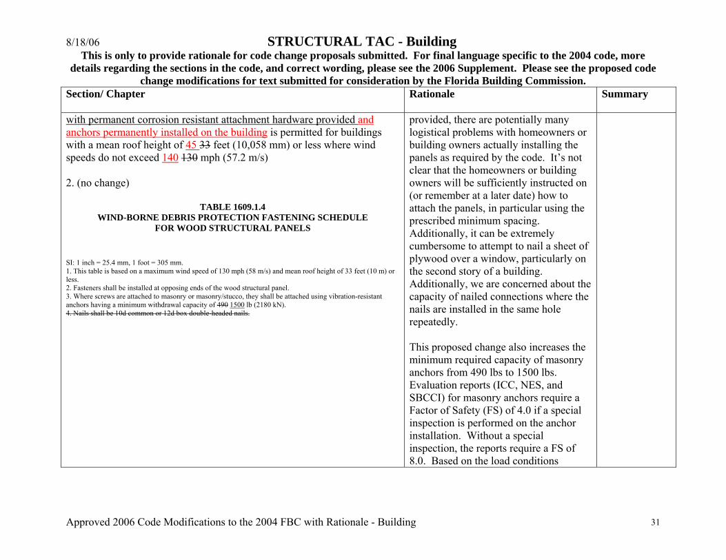
with permanent corrosion resistant attachment hardware provided and anchors permanently installed on the building is permitted for buildings with a mean roof height of 45 33 feet (10,058 mm) or less where wind speeds do not exceed 140 130 mph (57.2 m/s) 2. (no change)
TABLE 1609.1.4 WIND-BORNE DEBRIS PROTECTION FASTENING SCHEDULE
FOR WOOD STRUCTURAL PANELS
SI: 1 inch = 25.4 mm, 1 foot = 305 mm. 1. This table is based on a maximum wind speed of 130 mph (58 m/s) and mean roof height of 33 feet (10 m) or less. 2. Fasteners shall be installed at opposing ends of the wood structural panel. 3. Where screws are attached to masonry or masonry/stucco, they shall be attached using vibration-resistant anchors having a minimum withdrawal capacity of 490 1500 lb (2180 kN). 4. Nails shall be 10d common or 12d box double-headed nails.
provided, there are potentially many logistical problems with homeowners or building owners actually installing the panels as required by the code. It’s not clear that the homeowners or building owners will be sufficiently instructed on (or remember at a later date) how to attach the panels, in particular using the prescribed minimum spacing. Additionally, it can be extremely cumbersome to attempt to nail a sheet of plywood over a window, particularly on the second story of a building. Additionally, we are concerned about the capacity of nailed connections where the nails are installed in the same hole repeatedly. This proposed change also increases the minimum required capacity of masonry anchors from 490 lbs to 1500 lbs. Evaluation reports (ICC, NES, and SBCCI) for masonry anchors require a Factor of Safety (FS) of 4.0 if a special inspection is performed on the anchor installation. Without a special inspection, the reports require a FS of 8.0. Based on the load conditions
8/18/06 STRUCTURAL TAC - Building This is only to provide rationale for code change proposals submitted. For final language specific to the 2004 code, more
details regarding the sections in the code, and correct wording, please see the 2006 Supplement. Please see the proposed code change modifications for text submitted for consideration by the Florida Building Commission.
Approved 2006 Code Modifications to the 2004 FBC with Rationale - Building 32
Section/ Chapter
Rationale Summary
specified, the 490 lb required capacity implies a FS of 2.5. We do not believe that special inspections are or will be performed on these anchors. Therefore, raising the required capacity of the masonry anchors to 1500 lbs provides a FS more in line with the evaluation reports for masonry anchors. The change proposed is consistent with the IBHS Guidelines for Hurricane Resistant Construction. This document is based on SSTD 10-99 and the IBHS Guidelines reflect updates to SSTD 10 to allow the use of the prescriptive solutions in higher wind speed areas.
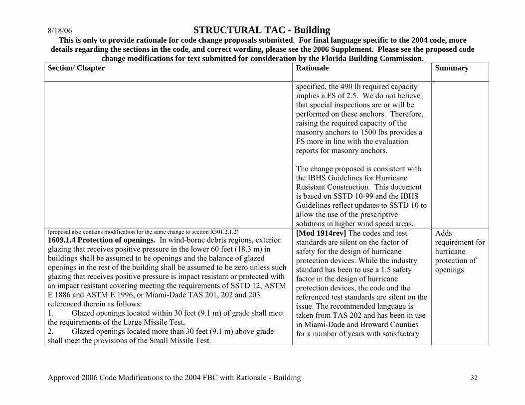
(proposal also contains modification for the same change to section R301.2.1.2) 1609.1.4 Protection of openings. In wind-borne debris regions, exterior glazing that receives positive pressure in the lower 60 feet (18.3 m) in buildings shall be assumed to be openings and the balance of glazed openings in the rest of the building shall be assumed to be zero unless such glazing that receives positive pressure is impact resistant or protected with an impact resistant covering meeting the requirements of SSTD 12, ASTM E 1886 and ASTM E 1996, or Miami-Dade TAS 201, 202 and 203 referenced therein as follows: 1. Glazed openings located within 30 feet (9.1 m) of grade shall meet the requirements of the Large Missile Test. 2. Glazed openings located more than 30 feet (9.1 m) above grade shall meet the provisions of the Small Missile Test.
[Mod 1914rev] The codes and test standards are silent on the factor of safety for the design of hurricane protection devices. While the industry standard has been to use a 1.5 safety factor in the design of hurricane protection devices, the code and the referenced test standards are silent on the issue. The recommended language is taken from TAS 202 and has been in use in Miami-Dade and Broward Counties for a number of years with satisfactory
Adds requirement for hurricane protection of openings
8/18/06 STRUCTURAL TAC - Building This is only to provide rationale for code change proposals submitted. For final language specific to the 2004 code, more
details regarding the sections in the code, and correct wording, please see the 2006 Supplement. Please see the proposed code change modifications for text submitted for consideration by the Florida Building Commission.
Approved 2006 Code Modifications to the 2004 FBC with Rationale - Building 33
Section/ Chapter
Rationale Summary
3. Storage sheds that are not designed for human habitation and that have a floor area of 720 square feet (67 m2) or less are not required to comply with the mandatory windborne debris impact standards of this code. 4. Openings in sunrooms, balconies or enclosed porches constructed under existing roofs or decks are not required to be protected provided the spaces are separated from the building interior by a wall and all openings in the separating wall are protected in accordance with Section 1609.1.4 above. Such spaces shall be permitted to be designed as either partially enclosed or enclosed structures. Impact resistant coverings shall be tested at 1.5 times the design pressure (positive or negative) expressed in pounds per square feet as determined by the Florida Building Code, Building Section 1609 for which the specimen is to be tested.
results.
1609.3 Basic wind speed. The basic wind speed in miles per hour, for the development of windloads, shall be determined from Figure1609. Basic wind speed for the special wind regions indicated, near mountainous terrain and near gorges shall be in accordance with local jurisdiction requirements. The exact location of wind speed lines shall be established by local ordinance using recognized physical landmarks such as major roads, canals, rivers and lake shores whenever possible.
[Mod 1922] None of the special wind regions exist in Florida nor are they shown on the map.
Deletes “special wind regions” reference in text
FIGURE 1609.6A APPLICATION OF MAIN WIND FORCE RESISTING SYSTEM LOADS FOR SIMPLE DIAPHRAGM BUILDS
[Mod 1729] Will provide clarity and consistency with ASCE 7-02
Editorial change by staff

8/18/06 STRUCTURAL TAC - Building This is only to provide rationale for code change proposals submitted. For final language specific to the 2004 code, more
details regarding the sections in the code, and correct wording, please see the 2006 Supplement. Please see the proposed code change modifications for text submitted for consideration by the Florida Building Commission.
Approved 2006 Code Modifications to the 2004 FBC with Rationale - Building 34
Section/ Chapter
Rationale Summary
Add the following Figure:
FIGURE 1609.6.2.1 MAIN WIND FORCE LOADING DIAGRAM

8/18/06 STRUCTURAL TAC - Building This is only to provide rationale for code change proposals submitted. For final language specific to the 2004 code, more
details regarding the sections in the code, and correct wording, please see the 2006 Supplement. Please see the proposed code change modifications for text submitted for consideration by the Florida Building Commission.
Approved 2006 Code Modifications to the 2004 FBC with Rationale - Building 35
Section/ Chapter
Rationale Summary
For SI: 1 foot = 304.8 mm, 1 degree = 0.0174 rad. Notes: 1. Pressures are applied to the horizontal and vertical projections for Exposure B, at h = 30 feet, for Iw = 1.0. Adjust to other exposures and heights with adjustment factor . 2. The load patterns shown shall be applied to each corner of the building in turn as the reference corner. 3. For the design of the longitudinal MWFRS, use θ = 0°, and locate the Zone E/F, G/H boundary at the mid-length of the building. 4. Load Cases 1 and 2 must be checked for 25° < θ = 45°. Load Case 2 at 25° is provided only for interpolation between 25° to 30°. 5. Plus and minus signs signify pressures acting toward and away from the projected surfaces, respectively. 6. For roof slopes other than those shown, linear interpolation is permitted. 7. The total horizontal load shall not be less than that determined by assuming pS = 0 in Zones B and D.
8/18/06 STRUCTURAL TAC - Building This is only to provide rationale for code change proposals submitted. For final language specific to the 2004 code, more
details regarding the sections in the code, and correct wording, please see the 2006 Supplement. Please see the proposed code change modifications for text submitted for consideration by the Florida Building Commission.
Approved 2006 Code Modifications to the 2004 FBC with Rationale - Building 36
Section/ Chapter
Rationale Summary
8. The zone pressures represent the following: Horizontal pressure zones — Sum of the windward and leeward net (sum of internal and external) pressures on vertical projection of: A – End zone of wall C – Interior zone of wall B – End zone of roof D – Interior zone of roof Vertical pressure zones — Net (sum of internal and external) pressures on horizontal projection of: E – End zone of windward roof G – Interior zone of windward roof F – End zone of leeward roof H – Interior zone of leeward roof 9. Where Zone E or G falls on a roof overhang on the windward side of the building, use EOH and GOH for the pressure on the horizontal projection of the overhang. Overhangs on the leeward and side edges shall have the basic zone pressure applied. 10. Notation: a: 10 percent of least horizontal dimension or 0.4h, whichever is smaller, but not less than either 4 percent of least horizontal dimension or 3 feet. h: Mean roof height, in feet (meters), except that eave height shall be used for roof angles < 10°. θ: Angle of plane of roof from horizontal, in degrees.
FIGURE 1609.6B MAIN WIND FORCE LOADING DIAGRAM [Mod 1738] Will provide clarity and consistency with ASCE 7-02
Editorial change by staff

8/18/06 STRUCTURAL TAC - Building This is only to provide rationale for code change proposals submitted. For final language specific to the 2004 code, more
details regarding the sections in the code, and correct wording, please see the 2006 Supplement. Please see the proposed code change modifications for text submitted for consideration by the Florida Building Commission.
Approved 2006 Code Modifications to the 2004 FBC with Rationale - Building 37
Section/ Chapter
Rationale Summary
Add the following Figure:
FIGURE 1609.6.2.1 MAIN WIND FORCE LOADING DIAGRAM
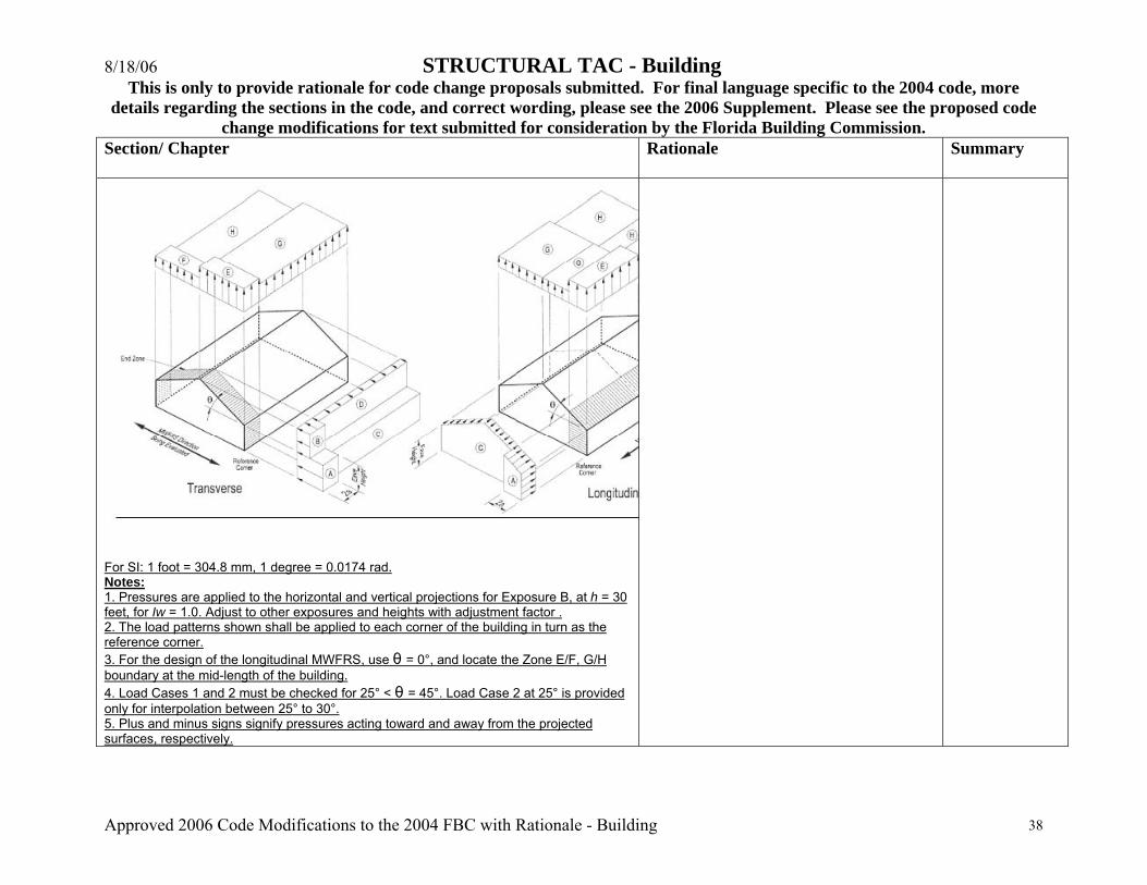
8/18/06 STRUCTURAL TAC - Building This is only to provide rationale for code change proposals submitted. For final language specific to the 2004 code, more
details regarding the sections in the code, and correct wording, please see the 2006 Supplement. Please see the proposed code change modifications for text submitted for consideration by the Florida Building Commission.
Approved 2006 Code Modifications to the 2004 FBC with Rationale - Building 38
Section/ Chapter
Rationale Summary
For SI: 1 foot = 304.8 mm, 1 degree = 0.0174 rad. Notes: 1. Pressures are applied to the horizontal and vertical projections for Exposure B, at h = 30 feet, for Iw = 1.0. Adjust to other exposures and heights with adjustment factor . 2. The load patterns shown shall be applied to each corner of the building in turn as the reference corner. 3. For the design of the longitudinal MWFRS, use θ = 0°, and locate the Zone E/F, G/H boundary at the mid-length of the building. 4. Load Cases 1 and 2 must be checked for 25° < θ = 45°. Load Case 2 at 25° is provided only for interpolation between 25° to 30°. 5. Plus and minus signs signify pressures acting toward and away from the projected surfaces, respectively.
8/18/06 STRUCTURAL TAC - Building This is only to provide rationale for code change proposals submitted. For final language specific to the 2004 code, more
details regarding the sections in the code, and correct wording, please see the 2006 Supplement. Please see the proposed code change modifications for text submitted for consideration by the Florida Building Commission.
Approved 2006 Code Modifications to the 2004 FBC with Rationale - Building 39
Section/ Chapter
Rationale Summary
6. For roof slopes other than those shown, linear interpolation is permitted. 7. The total horizontal load shall not be less than that determined by assuming pS = 0 in Zones B and D. 8. The zone pressures represent the following: Horizontal pressure zones — Sum of the windward and leeward net (sum of internal and external) pressures on vertical projection of: A – End zone of wall C – Interior zone of wall B – End zone of roof D – Interior zone of roof Vertical pressure zones — Net (sum of internal and external) pressures on horizontal projection of: E – End zone of windward roof G – Interior zone of windward roof F – End zone of leeward roof H – Interior zone of leeward roof 9. Where Zone E or G falls on a roof overhang on the windward side of the building, use EOH and GOH for the pressure on the horizontal projection of the overhang. Overhangs on the leeward and side edges shall have the basic zone pressure applied. 10. Notation: a: 10 percent of least horizontal dimension or 0.4h, whichever is smaller, but not less than either 4 percent of least horizontal dimension or 3 feet. h: Mean roof height, in feet (meters), except that eave height shall be used for roof angles < 10°. θ: Angle of plane of roof from horizontal, in degrees.
FIGURE 1609.6C COMPONENT AND CLADDING LOADING DIAGRAMS
[Mod 1737] Will provide clarity and consistency with ASCE 7-02
Editorial change by staff
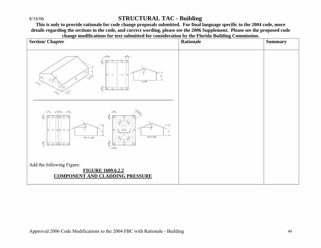
8/18/06 STRUCTURAL TAC - Building This is only to provide rationale for code change proposals submitted. For final language specific to the 2004 code, more
details regarding the sections in the code, and correct wording, please see the 2006 Supplement. Please see the proposed code change modifications for text submitted for consideration by the Florida Building Commission.
Approved 2006 Code Modifications to the 2004 FBC with Rationale - Building 40
Section/ Chapter
Rationale Summary
Add the following Figure:
FIGURE 1609.6.2.2 COMPONENT AND CLADDING PRESSURE
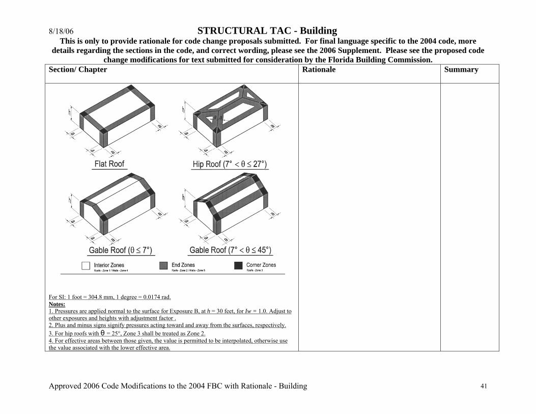
8/18/06 STRUCTURAL TAC - Building This is only to provide rationale for code change proposals submitted. For final language specific to the 2004 code, more
details regarding the sections in the code, and correct wording, please see the 2006 Supplement. Please see the proposed code change modifications for text submitted for consideration by the Florida Building Commission.
Approved 2006 Code Modifications to the 2004 FBC with Rationale - Building 41
Section/ Chapter
Rationale Summary
For SI: 1 foot = 304.8 mm, 1 degree = 0.0174 rad. Notes: 1. Pressures are applied normal to the surface for Exposure B, at h = 30 feet, for Iw = 1.0. Adjust to other exposures and heights with adjustment factor . 2. Plus and minus signs signify pressures acting toward and away from the surfaces, respectively. 3. For hip roofs with θ = 25°, Zone 3 shall be treated as Zone 2. 4. For effective areas between those given, the value is permitted to be interpolated, otherwise use the value associated with the lower effective area.
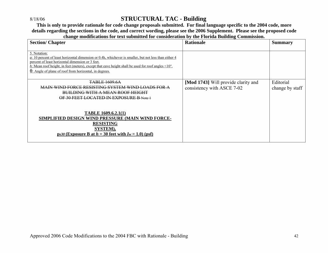
8/18/06 STRUCTURAL TAC - Building This is only to provide rationale for code change proposals submitted. For final language specific to the 2004 code, more
details regarding the sections in the code, and correct wording, please see the 2006 Supplement. Please see the proposed code change modifications for text submitted for consideration by the Florida Building Commission.
Approved 2006 Code Modifications to the 2004 FBC with Rationale - Building 42
Section/ Chapter
Rationale Summary
5. Notation: a: 10 percent of least horizontal dimension or 0.4h, whichever is smaller, but not less than either 4 percent of least horizontal dimension or 3 feet. h: Mean roof height, in feet (meters), except that eave height shall be used for roof angles <10°. θ: Angle of plane of roof from horizontal, in degrees.
TABLE 1609.6A MAIN WIND FORCE RESISTING SYSTEM WIND LOADS FOR A
BUILDING WITH A MEAN ROOF HEIGHT OF 30 FEET LOCATED IN EXPOSURE B Note 1
TABLE 1609.6.2.1(1) SIMPLIFIED DESIGN WIND PRESSURE (MAIN WIND FORCE-
RESISTING SYSTEM),
ps30 (Exposure B at h = 30 feet with Iw = 1.0) (psf)
[Mod 1743] Will provide clarity and consistency with ASCE 7-02
Editorial change by staff
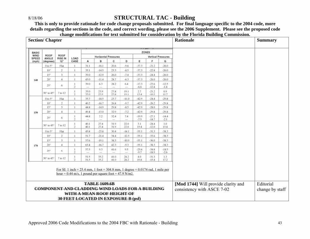
8/18/06 STRUCTURAL TAC - Building This is only to provide rationale for code change proposals submitted. For final language specific to the 2004 code, more
details regarding the sections in the code, and correct wording, please see the 2006 Supplement. Please see the proposed code change modifications for text submitted for consideration by the Florida Building Commission.
Approved 2006 Code Modifications to the 2004 FBC with Rationale - Building 43
Section/ Chapter
Rationale Summary
For SI: 1 inch = 25.4 mm, 1 foot = 304.8 mm, 1 degree = 0.0174 rad, 1 mile per hour = 0.44 m/s, 1 pound per square foot = 47.9 N/m2.
TABLE 1609.6B
COMPONENT AND CLADDING WIND LOADS FOR A BUILDING WITH A MEAN ROOF HEIGHT OF
30 FEET LOCATED IN EXPOSURE B (psf)
[Mod 1744] Will provide clarity and consistency with ASCE 7-02
Editorial change by staff

8/18/06 STRUCTURAL TAC - Building This is only to provide rationale for code change proposals submitted. For final language specific to the 2004 code, more
details regarding the sections in the code, and correct wording, please see the 2006 Supplement. Please see the proposed code change modifications for text submitted for consideration by the Florida Building Commission.
Approved 2006 Code Modifications to the 2004 FBC with Rationale - Building 44
Section/ Chapter
Rationale Summary
BASIC WIND SPEED V (mph - 3-second gust) ZONE 3 EFFECTIVE WIND AREA (ft 2 )
85 90 100 110
1 10 10.0 -13.0 10.0 -14.6 10.0 -18.0 10.0 -21.8
1 20 10.0 -12.7 10.0 -14.2 10.0 -17.5 10.0 -21.2
1 50 10.0 -12.2 10.0 -13.7 10.0 -16.9 10.0 -20.5
1 100 10.0 -11.9 10.0 -13.3 10.0 -16.5 10.0 -19.9
2 10 10.0 -21.8 10.0 -24.4 10.0 -30.2 10.0 -36.5
2 20 10.0 -19.5 10.0 -21.8 10.0 -27.0 10.0 -32.6
2 50 10.0 -16.4 10.0 -18.4 10.0 -22.7 10.0 -27.5
2 100 10.0 -14.1 10.0 -15.8 10.0 -19.5 10.0 -23.6
3 10 10.0 -32.8 10.0 -36.8 10.0 -45.4 10.0 -55.0
3 20 10.0 -27.2 10.0 -30.5 10.0 -37.6 10.0 -45.5
3 50 10.0 -19.7 10.0 -22.1 10.0 -27.3 10.0 -33.1
Roof > 0
to 10 Degrees
3 100 10.0 -14.1 10.0 -15.8 10.0 -19.5 10.0 -23.6
1 10 10.0 -11.9 10.0 -13.3 10.4 -16.5 12.5 -19.9 Roof > 10 to 30
Degrees 1 20 10.0 -11.6 10.0 -13.0 10.0 -16.0 11.4 -19.4
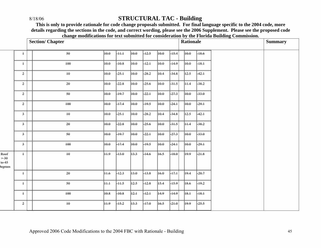
8/18/06 STRUCTURAL TAC - Building This is only to provide rationale for code change proposals submitted. For final language specific to the 2004 code, more
details regarding the sections in the code, and correct wording, please see the 2006 Supplement. Please see the proposed code change modifications for text submitted for consideration by the Florida Building Commission.
Approved 2006 Code Modifications to the 2004 FBC with Rationale - Building 45
Section/ Chapter
Rationale Summary
1 50 10.0 -11.1 10.0 -12.5 10.0 -15.4 10.0 -18.6
1 100 10.0 -10.8 10.0 -12.1 10.0 -14.9 10.0 -18.1
2 10 10.0 -25.1 10.0 -28.2 10.4 -34.8 12.5 -42.1
2 20 10.0 -22.8 10.0 -25.6 10.0 -31.5 11.4 -38.2
2 50 10.0 -19.7 10.0 -22.1 10.0 -27.3 10.0 -33.0
2 100 10.0 -17.4 10.0 -19.5 10.0 -24.1 10.0 -29.1
3 10 10.0 -25.1 10.0 -28.2 10.4 -34.8 12.5 -42.1
3 20 10.0 -22.8 10.0 -25.6 10.0 -31.5 11.4 -38.2
3 50 10.0 -19.7 10.0 -22.1 10.0 -27.3 10.0 -33.0
3 100 10.0 -17.4 10.0 -19.5 10.0 -24.1 10.0 -29.1
1 10 11.9 -13.0 13.3 -14.6 16.5 -18.0 19.9 -21.8
1 20 11.6 -12.3 13.0 -13.8 16.0 -17.1 19.4 -20.7
1 50 11.1 -11.5 12.5 -12.8 15.4 -15.9 18.6 -19.2
1 100 10.8 -10.8 12.1 -12.1 14.9 -14.9 18.1 -18.1
Roof > 30 to 45
Degrees
2 10 11.9 -15.2 13.3 -17.0 16.5 -21.0 19.9 -25.5
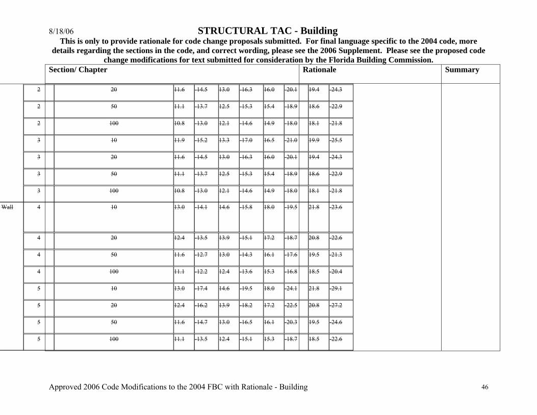
8/18/06 STRUCTURAL TAC - Building This is only to provide rationale for code change proposals submitted. For final language specific to the 2004 code, more
details regarding the sections in the code, and correct wording, please see the 2006 Supplement. Please see the proposed code change modifications for text submitted for consideration by the Florida Building Commission.
Approved 2006 Code Modifications to the 2004 FBC with Rationale - Building 46
Section/ Chapter
Rationale Summary
2 20 11.6 -14.5 13.0 -16.3 16.0 -20.1 19.4 -24.3
2 50 11.1 -13.7 12.5 -15.3 15.4 -18.9 18.6 -22.9
2 100 10.8 -13.0 12.1 -14.6 14.9 -18.0 18.1 -21.8
3 10 11.9 -15.2 13.3 -17.0 16.5 -21.0 19.9 -25.5
3 20 11.6 -14.5 13.0 -16.3 16.0 -20.1 19.4 -24.3
3 50 11.1 -13.7 12.5 -15.3 15.4 -18.9 18.6 -22.9
3 100 10.8 -13.0 12.1 -14.6 14.9 -18.0 18.1 -21.8
4 10 13.0 -14.1 14.6 -15.8 18.0 -19.5 21.8 -23.6
4 20 12.4 -13.5 13.9 -15.1 17.2 -18.7 20.8 -22.6
4 50 11.6 -12.7 13.0 -14.3 16.1 -17.6 19.5 -21.3
4 100 11.1 -12.2 12.4 -13.6 15.3 -16.8 18.5 -20.4
5 10 13.0 -17.4 14.6 -19.5 18.0 -24.1 21.8 -29.1
5 20 12.4 -16.2 13.9 -18.2 17.2 -22.5 20.8 -27.2
5 50 11.6 -14.7 13.0 -16.5 16.1 -20.3 19.5 -24.6
Wall
5 100 11.1 -13.5 12.4 -15.1 15.3 -18.7 18.5 -22.6
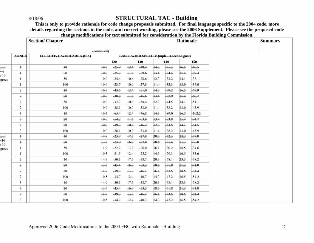
8/18/06 STRUCTURAL TAC - Building This is only to provide rationale for code change proposals submitted. For final language specific to the 2004 code, more
details regarding the sections in the code, and correct wording, please see the 2006 Supplement. Please see the proposed code change modifications for text submitted for consideration by the Florida Building Commission.
Approved 2006 Code Modifications to the 2004 FBC with Rationale - Building 47
Section/ Chapter
Rationale Summary
(continued) BASIC WIND SPEED V (mph - 3-second gust) ZONE 3 EFFECTIVE WIND AREA (ft 2 )
120 130 140 150 1 10 10.5 -25.9 12.4 -30.4 14.3 -35.3 16.5 -40.5 1 20 10.0 -25.2 11.6 -29.6 13.4 -34.4 15.4 -39.4 1 50 10.0 -24.4 10.6 -28.6 12.3 -33.2 14.1 -38.1 1 100 10.0 -23.7 10.0 -27.8 11.4 -32.3 13.0 -37.0 2 10 10.5 -43.5 12.4 -51.0 14.3 -59.2 16.5 -67.9 2 20 10.0 -38.8 11.6 -45.6 13.4 -52.9 15.4 -60.7 2 50 10.0 -32.7 10.6 -38.4 12.3 -44.5 14.1 -51.1 2 100 10.0 -28.1 10.0 -33.0 11.4 -38.2 13.0 -43.9 3 10 10.5 -65.4 12.4 -76.8 14.3 -89.0 16.5 -102.2 3 20 10.0 -54.2 11.6 -63.6 13.4 -73.8 15.4 -84.7 3 50 10.0 -39.3 10.6 -46.2 12.3 -53.5 14.1 -61.5
Roof > 0 o 10 egrees
3 100 10.0 -28.1 10.0 -33.0 11.4 -38.2 13.0 -43.9 1 10 14.9 -23.7 17.5 -27.8 20.3 -32.3 23.3 -37.0 1 20 13.6 -23.0 16.0 -27.0 18.5 -31.4 21.3 -36.0 1 50 11.9 -22.2 13.9 -26.0 16.1 -30.2 18.5 -34.6 1 100 10.5 -21.5 12.4 -25.2 14.3 -29.3 16.5 -33.6 2 10 14.9 -50.1 17.5 -58.7 20.3 -68.1 23.3 -78.2 2 20 13.6 -45.4 16.0 -53.3 18.5 -61.8 21.3 -71.0 2 50 11.9 -39.3 13.9 -46.1 16.1 -53.5 18.5 -61.4 2 100 10.5 -34.7 12.4 -40.7 14.3 -47.2 16.5 -54.2 3 10 14.9 -50.1 17.5 -58.7 20.3 -68.1 23.3 -78.2 3 20 13.6 -45.4 16.0 -53.5 18.5 -61.8 21.3 -71.0 3 50 11.9 -39.3 13.9 -46.1 16.1 -53.5 18.5 -61.4
Roof > 10 o 30 egrees
3 100 10.5 -34.7 12.4 -40.7 14.3 -47.2 16.5 -54.2

8/18/06 STRUCTURAL TAC - Building This is only to provide rationale for code change proposals submitted. For final language specific to the 2004 code, more
details regarding the sections in the code, and correct wording, please see the 2006 Supplement. Please see the proposed code change modifications for text submitted for consideration by the Florida Building Commission.
Approved 2006 Code Modifications to the 2004 FBC with Rationale - Building 48
Section/ Chapter
Rationale Summary
1 10 23.7 -25.9 27.8 -30.4 32.3 -35.3 37.0 -40.5 1 20 23.0 -24.6 27.0 -28.9 31.4 -33.5 36.0 -38.4 1 50 22.2 -22.8 26.0 -26.8 30.2 -31.1 34.6 -35.7 1 100 21.5 -21.5 25.2 -25.2 29.3 -29.3 33.6 -33.6 2 10 23.7 -30.3 27.8 -35.6 32.3 -41.2 37.0 -47.3 2 20 23.0 -29.0 27.0 -34.0 31.4 -39.4 36.0 -45.3 2 50 22.2 -27.2 26.0 -32.0 30.2 -37.1 34.6 -42.5 2 100 21.5 -25.9 25.2 -30.4 29.3 -35.3 33.6 -40.5 3 10 23.7 -30.3 27.8 -35.6 32.3 -41.2 37.0 -47.3 3 20 23.0 -29.0 27.0 -34.0 31.4 -39.4 36.0 -45.3 3 50 22.2 -27.2 26.0 -32.0 30.2 -37.1 34.6 -42.5
Roof > 30 o 45 egrees
3 100 21.5 -25.9 25.2 -30.4 29.3 -35.3 33.6 -40.5 4 10 25.9 -28.1 30.4 -33.0 35.3 -38.2 40.5 -43.9 4 20 24.7 -26.9 29.0 -31.6 33.7 -36.7 38.7 -42.1 4 50 23.2 -25.4 27.2 -29.8 31.6 -34.6 36.2 -39.7 4 100 22.0 -24.2 25.9 -28.4 30.0 -33.0 34.4 -37.8 5 10 25.9 -34.7 30.4 -40.7 35.3 -47.2 40.5 -54.2 5 20 24.7 -32.4 29.0 -38.0 33.7 44.0 38.7 -50.5 5 50 23.2 -29.3 27.2 -34.3 31.6 -39.8 36.2 -45.7
Wall
5 100 22.0 -26.9 25.9 -31.6 30.0 -36.7 34.4 -42.1 For SI: 1 square foot = 0.0929 m 2 , 1 mph = 0.447 m/s, 1 psf = 47.88 N/m 2 . 1. For effective areas or wind speeds between those given above the load may be interpolated, otherwise use the load associated with the lower effective area. 2. Table values shall be adjusted for height and exposure by multiplying by adjustment coefficients in Table 1609.6D . 3. See Figure 1609.6C for location of zones. 4. Plus and minus signs signify pressures acting toward and away from the building surfaces

8/18/06 STRUCTURAL TAC - Building This is only to provide rationale for code change proposals submitted. For final language specific to the 2004 code, more
details regarding the sections in the code, and correct wording, please see the 2006 Supplement. Please see the proposed code change modifications for text submitted for consideration by the Florida Building Commission.
Approved 2006 Code Modifications to the 2004 FBC with Rationale - Building 49
Section/ Chapter
Rationale Summary
TABLE 1609.6.2.1(2) NET DESIGN WIND PRESSURE (COMPONENT AND CLADDING), pnet30
(Exposure B at h= 30 feet with Iw = 1.0) (psf)
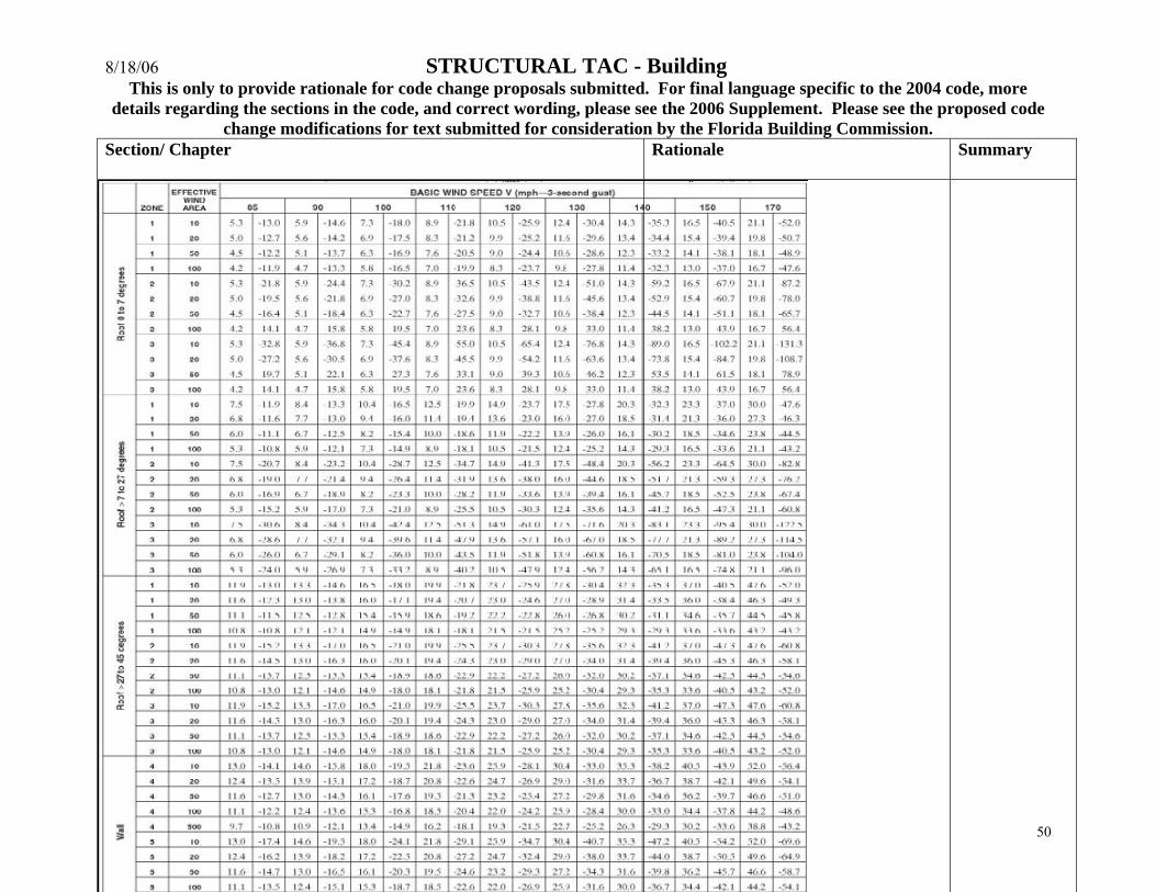
8/18/06 STRUCTURAL TAC - Building This is only to provide rationale for code change proposals submitted. For final language specific to the 2004 code, more
details regarding the sections in the code, and correct wording, please see the 2006 Supplement. Please see the proposed code change modifications for text submitted for consideration by the Florida Building Commission.
Approved 2006 Code Modifications to the 2004 FBC with Rationale - Building 50
Section/ Chapter
Rationale Summary
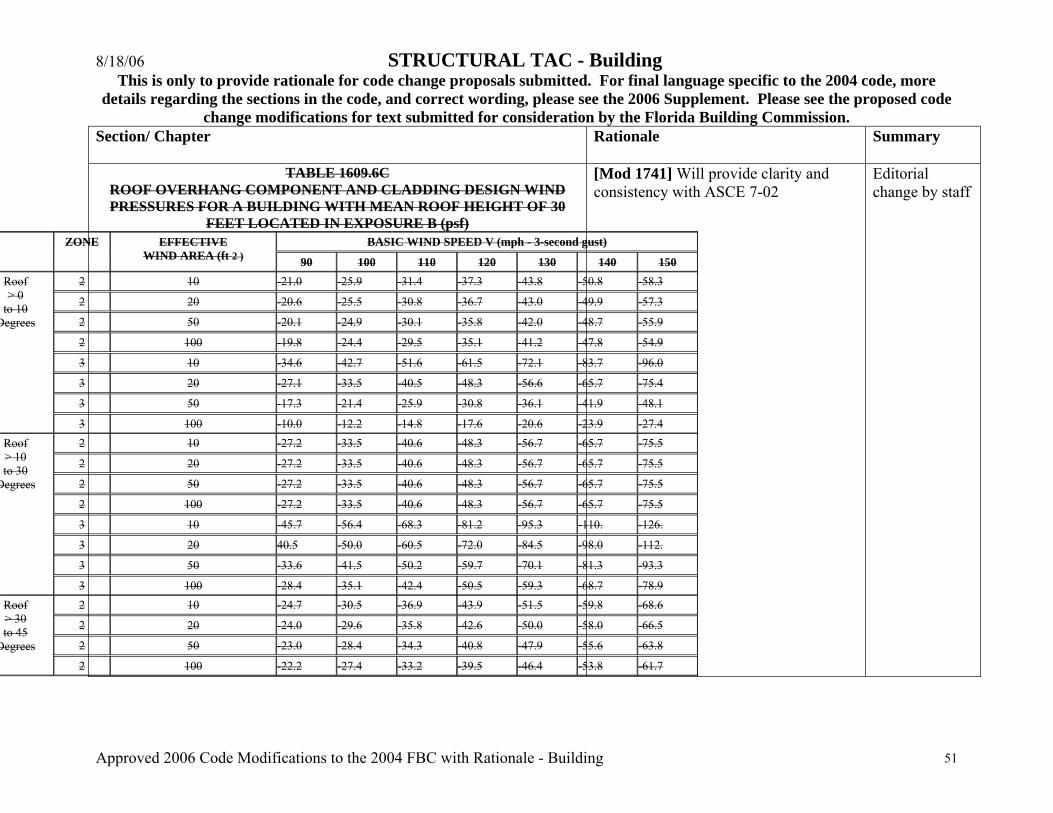
8/18/06 STRUCTURAL TAC - Building This is only to provide rationale for code change proposals submitted. For final language specific to the 2004 code, more
details regarding the sections in the code, and correct wording, please see the 2006 Supplement. Please see the proposed code change modifications for text submitted for consideration by the Florida Building Commission.
Approved 2006 Code Modifications to the 2004 FBC with Rationale - Building 51
Section/ Chapter
Rationale Summary
TABLE 1609.6C ROOF OVERHANG COMPONENT AND CLADDING DESIGN WIND PRESSURES FOR A BUILDING WITH MEAN ROOF HEIGHT OF 30
FEET LOCATED IN EXPOSURE B (psf) BASIC WIND SPEED V (mph - 3-second gust) ZONE EFFECTIVE
WIND AREA (ft 2 ) 90 100 110 120 130 140 150 2 10 -21.0 -25.9 -31.4 -37.3 -43.8 -50.8 -58.3
2 20 -20.6 -25.5 -30.8 -36.7 -43.0 -49.9 -57.3
2 50 -20.1 -24.9 -30.1 -35.8 -42.0 -48.7 -55.9
2 100 -19.8 -24.4 -29.5 -35.1 -41.2 -47.8 -54.9
3 10 -34.6 -42.7 -51.6 -61.5 -72.1 -83.7 -96.0
3 20 -27.1 -33.5 -40.5 -48.3 -56.6 -65.7 -75.4
3 50 -17.3 -21.4 -25.9 -30.8 -36.1 -41.9 -48.1
Roof > 0
to 10 Degrees
3 100 -10.0 -12.2 -14.8 -17.6 -20.6 -23.9 -27.4 2 10 -27.2 -33.5 -40.6 -48.3 -56.7 -65.7 -75.5
2 20 -27.2 -33.5 -40.6 -48.3 -56.7 -65.7 -75.5
2 50 -27.2 -33.5 -40.6 -48.3 -56.7 -65.7 -75.5
2 100 -27.2 -33.5 -40.6 -48.3 -56.7 -65.7 -75.5
3 10 -45.7 -56.4 -68.3 -81.2 -95.3 -110. -126.
3 20 40.5 -50.0 -60.5 -72.0 -84.5 -98.0 -112.
3 50 -33.6 -41.5 -50.2 -59.7 -70.1 -81.3 -93.3
Roof > 10 to 30
Degrees
3 100 -28.4 -35.1 -42.4 -50.5 -59.3 -68.7 -78.9 2 10 -24.7 -30.5 -36.9 -43.9 -51.5 -59.8 -68.6
2 20 -24.0 -29.6 -35.8 -42.6 -50.0 -58.0 -66.5
2 50 -23.0 -28.4 -34.3 -40.8 -47.9 -55.6 -63.8
Roof > 30 to 45
Degrees
2 100 -22.2 -27.4 -33.2 -39.5 -46.4 -53.8 -61.7
[Mod 1741] Will provide clarity and consistency with ASCE 7-02
Editorial change by staff

8/18/06 STRUCTURAL TAC - Building This is only to provide rationale for code change proposals submitted. For final language specific to the 2004 code, more
details regarding the sections in the code, and correct wording, please see the 2006 Supplement. Please see the proposed code change modifications for text submitted for consideration by the Florida Building Commission.
Approved 2006 Code Modifications to the 2004 FBC with Rationale - Building 52
Section/ Chapter
Rationale Summary
3 10 -24.7 -30.5 -36.9 -43.9 -51.5 -59.8 -68.6
3 20 -24.0 -29.6 -35.8 -42.6 -50.0 -58.0 -66.5
3 50 -23.0 -28.4 -34.3 -40.8 -47.9 -55.6 -63.8
3 100 -22.2 -27.4 -33.2 -39.5 -46.4 -53.8 -61.7 For SI: 1 psf = 47.88 N/m 2 , 1 ft^2 = 0.0929 m 2 , 1 mph = 0.447 m/s. NOTE: For effective areas between those given above the load may be interpolated, otherwise use the load associated with the lower effective area.
TABLE 1609.6.2.1(3) ROOF OVERHANG NET DESIGN WIND PRESSURE (COMPONENT
AND
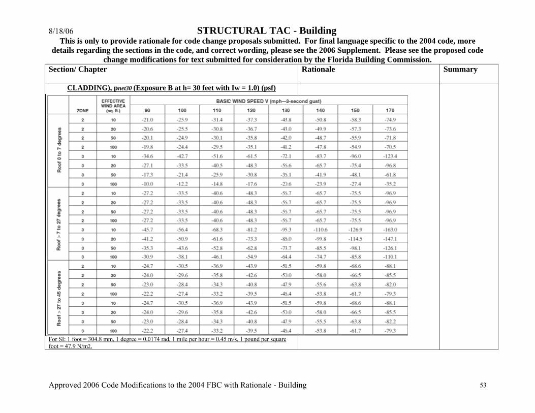
8/18/06 STRUCTURAL TAC - Building This is only to provide rationale for code change proposals submitted. For final language specific to the 2004 code, more
details regarding the sections in the code, and correct wording, please see the 2006 Supplement. Please see the proposed code change modifications for text submitted for consideration by the Florida Building Commission.
Approved 2006 Code Modifications to the 2004 FBC with Rationale - Building 53
Section/ Chapter
Rationale Summary
CLADDING), pnet30 (Exposure B at h= 30 feet with Iw = 1.0) (psf)
For SI: 1 foot = 304.8 mm, 1 degree = 0.0174 rad, 1 mile per hour = 0.45 m/s, 1 pound per square foot = 47.9 N/m2.
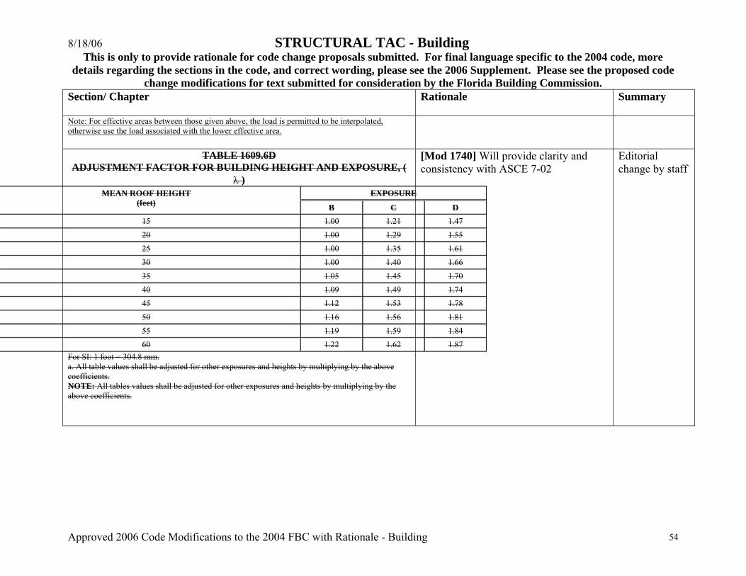
8/18/06 STRUCTURAL TAC - Building This is only to provide rationale for code change proposals submitted. For final language specific to the 2004 code, more
details regarding the sections in the code, and correct wording, please see the 2006 Supplement. Please see the proposed code change modifications for text submitted for consideration by the Florida Building Commission.
Approved 2006 Code Modifications to the 2004 FBC with Rationale - Building 54
Section/ Chapter
Rationale Summary
Note: For effective areas between those given above, the load is permitted to be interpolated, otherwise use the load associated with the lower effective area.
TABLE 1609.6D ADJUSTMENT FACTOR FOR BUILDING HEIGHT AND EXPOSURE, (
λ ) EXPOSURE MEAN ROOF HEIGHT
(feet) B C D 15 1.00 1.21 1.47 20 1.00 1.29 1.55 25 1.00 1.35 1.61 30 1.00 1.40 1.66 35 1.05 1.45 1.70 40 1.09 1.49 1.74 45 1.12 1.53 1.78 50 1.16 1.56 1.81 55 1.19 1.59 1.84 60 1.22 1.62 1.87
For SI: 1 foot = 304.8 mm. a. All table values shall be adjusted for other exposures and heights by multiplying by the above coefficients. NOTE: All tables values shall be adjusted for other exposures and heights by multiplying by the above coefficients.
[Mod 1740] Will provide clarity and consistency with ASCE 7-02
Editorial change by staff
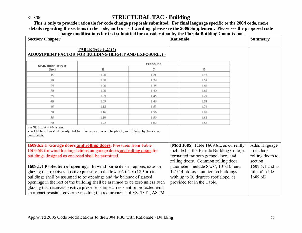
8/18/06 STRUCTURAL TAC - Building This is only to provide rationale for code change proposals submitted. For final language specific to the 2004 code, more
details regarding the sections in the code, and correct wording, please see the 2006 Supplement. Please see the proposed code change modifications for text submitted for consideration by the Florida Building Commission.
Approved 2006 Code Modifications to the 2004 FBC with Rationale - Building 55
Section/ Chapter
Rationale Summary
TABLE 1609.6.2.1(4) ADJUSTMENT FACTOR FOR BUILDING HEIGHT AND EXPOSURE, ( )
For SI: 1 foot = 304.8 mm. a. All table values shall be adjusted for other exposures and heights by multiplying by the above coefficients. 1609.6.5.1 Garage doors and rolling doors. Pressures from Table 1609.6E for wind loading actions on garage doors and rolling doors for buildings designed as enclosed shall be permitted. 1609.1.4 Protection of openings. In wind-borne debris regions, exterior glazing that receives positive pressure in the lower 60 feet (18.3 m) in buildings shall be assumed to be openings and the balance of glazed openings in the rest of the building shall be assumed to be zero unless such glazing that receives positive pressure is impact resistant or protected with an impact resistant covering meeting the requirements of SSTD 12, ASTM
[Mod 1085] Table 1609.6E, as currently included in the Florida Building Code, is formatted for both garage doors and rolling doors. Common rolling door parameters include 8’x8’, 10’x10’ and 14’x14’ doors mounted on buildings with up to 10 degrees roof slope, as provided for in the Table.
Adds language to include rolling doors to section 1609.5.1 and to title of Table 1609.6E
8/18/06 STRUCTURAL TAC - Building This is only to provide rationale for code change proposals submitted. For final language specific to the 2004 code, more
details regarding the sections in the code, and correct wording, please see the 2006 Supplement. Please see the proposed code change modifications for text submitted for consideration by the Florida Building Commission.
Approved 2006 Code Modifications to the 2004 FBC with Rationale - Building 56
Section/ Chapter
Rationale Summary
E 1886 and ASTM E 1996, ANSI/DASMA 115 (for garage doors and rolling doors) or Miami-Dade TAS 201, 202 and 203 referenced therein as follows:… 1609.2.2.2 6.5.1 Garage doors and rolling doors. Pressures from Table 1604.6.2.1(5) Table 1609.E for wind loading actions on garage doors and rolling doors for buildings designed as enclosed shall be permitted. Table 1609.6E GARAGE DOOR AND ROLLING DOOR WIND LOADS FOR A BUILDING WITH A MEAN ROOF HEIGHT OF 30 FEET LOCATED IN EXPOSURE B (psf) (remainder of table unchanged)
Table 1609.6E 1609.2.1(5) GARAGE DOOR AND ROLLING DOOR WIND LOADS FOR A
BUILDING WITH A MEAN ROOF HEIGHT OF 30 FEET LOCATED IN EXPOSURE B (psf)
[Remainder of table unchanged.] [Mod 1747] Editorial change to be
consistent with the code format with regards to standard reference. Year edition is included in Chapter 35.
Editorial change by staff; Deletes year edition of ASCE 7 on map key
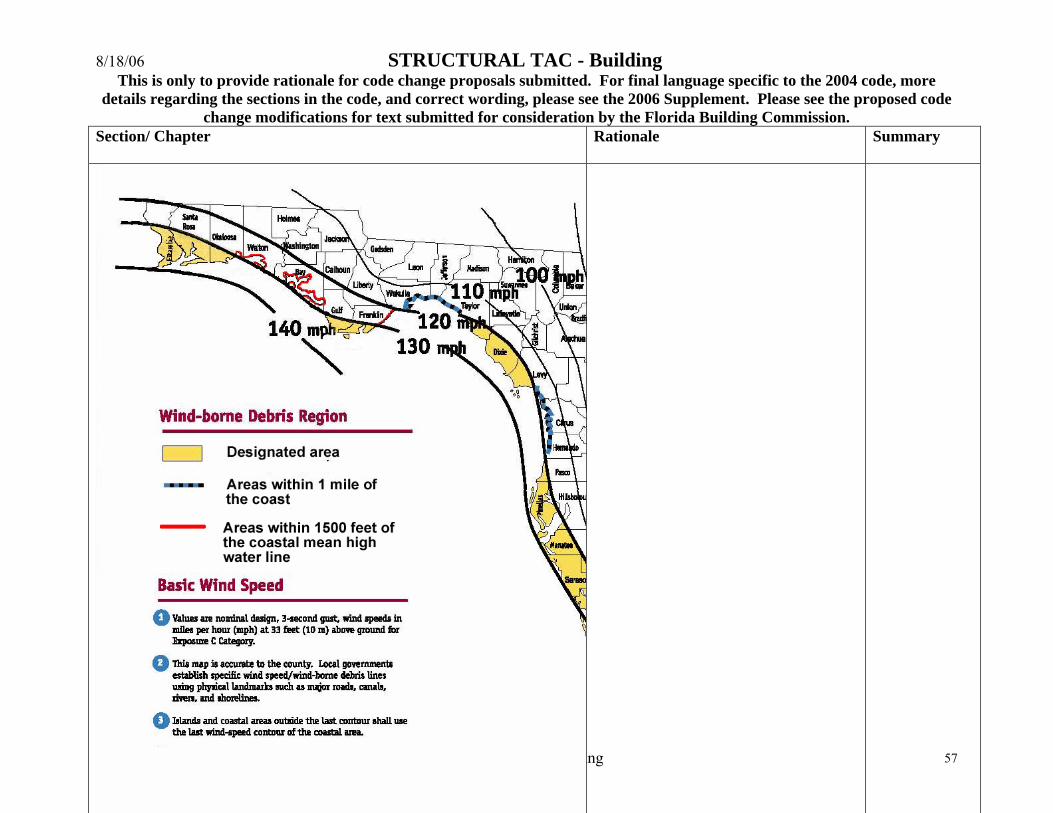
8/18/06 STRUCTURAL TAC - Building This is only to provide rationale for code change proposals submitted. For final language specific to the 2004 code, more
details regarding the sections in the code, and correct wording, please see the 2006 Supplement. Please see the proposed code change modifications for text submitted for consideration by the Florida Building Commission.
Approved 2006 Code Modifications to the 2004 FBC with Rationale - Building 57
Section/ Chapter
Rationale Summary
8/18/06 STRUCTURAL TAC - Building This is only to provide rationale for code change proposals submitted. For final language specific to the 2004 code, more
details regarding the sections in the code, and correct wording, please see the 2006 Supplement. Please see the proposed code change modifications for text submitted for consideration by the Florida Building Commission.
Approved 2006 Code Modifications to the 2004 FBC with Rationale - Building 58
Section/ Chapter
Rationale Summary
1618.9 Load Combination. The safety of structures shall be checked using provisions of 2.3 and 2.4 of ASCE 7 with commentary. Exception: Increases in allowable stress shall be permitted in accordance with ACI 530/ASCE 5/TMS 402 provided the load reduction factor of 0.75 of combinations 4 and 6 of ASCE 7 Section 2.4.3 1 shall not be applied.
[Mod 1182] ASCE 7 Section 2.4.3 mentioned in exception refers to ASCE 7- 98. Applicable standard now is ASCE 7- 02, therefore Section 2.4.3 must be revised to the correct reference to Section 2.4.1. The added factor of 0.75 and combination 4 and 6 of clarifies the intent.
Revises referenced section of ASCE 7 and adds text
1620.3 All buildings and structures shall be considered to be in Exposure Category C as defined in Section 6.5.6.13 of ASCE 7.
[Mod 1193] Section 1620.3 refers to Section 6.5.6.1 of ASCE 7- 98. New Applicable Standard is ASCE 7- 02, therefore reference must be revised to the correct Section 6.5.6.3 of ASCE - 02.
Revises referenced section of ASCE 7 in text
1624.2 Wind effects. Where the pressure on the foundation from wind is less than 25 percent of that resulting from dead or other live loads, wind pressure may be neglected in the footing design. 1624.2.1 Where this percentage exceeds 25 percent, foundations shall be so designed that the pressure resulting from the combined dead, live and wind loads shall not exceed the allowable soil-bearing values or allowable loads per pile by more than 25 percent.
[Mod 1175] The combined effects of two or more variable loads with dead load is accurately specified with a reduction factor of 0.75 in load combination 6 of Section 2.4.1 of American Society of Civil Engineers Standard ASCE 7- 02. Section 1624.2, which permits wind pressure to be neglected for the design of footing, if it is less than 25 % of dead or other live loads is not required in the code. Similarly Section 1624.2.1, which specifies 25 % increase in allowable bearing pressure for combined dead, live
Deletes both sections entirely
8/18/06 STRUCTURAL TAC - Building This is only to provide rationale for code change proposals submitted. For final language specific to the 2004 code, more
details regarding the sections in the code, and correct wording, please see the 2006 Supplement. Please see the proposed code change modifications for text submitted for consideration by the Florida Building Commission.
Approved 2006 Code Modifications to the 2004 FBC with Rationale - Building 59
Section/ Chapter
Rationale Summary
and wind loads and 25% increase in allowable loads per pile is not required in the code. Deletion of these two sections will avoid duplication and confusion.
1714.5.2.1 Testing and Labeling. Exterior windows and glass doors shall be tested by an approved independent testing laboratory, and shall be labeled with an approved label identifying the manufacturer, performance characteristics and approved product certification agency, testing laboratory, evaluation entity or Miami-Dade notice of acceptance to indicate compliance with the requirements of one of the following specifications:
ANSI/AAMA/NWWDA 101/I.S. 2 or 101/I.S. 2/NAFS or AAMA/WDMA/CSA 101/I.S. 2/A440 or TAS 202 (HVHZ shall comply with TAS 202 utilizing ASTM E 1300-98 or ASTM E 1300-02 or Section 2404).
Glass Strength: Products tested and labeled as conforming to AAMA/NWWDA 101/I.S.2 or 101/I.S.2/NAFS or AAMA/WDMA/CSA 101/I.S. 2/A440 or TAS 202 shall not be subject to the requirements of Sections 2403.2 or 2403.3 or 2404.1. Determination of load resistance of glass for specific loads of products not tested and certified in accordance with s. 1714.5.2.1 shall be designed and labeled to comply with ASTM E 1300.in accordance with Section 2404. The label shall designate the type and thickness of glass or glazing material.
[Mod 1852rev] To be able to continue to provide the same level of protection for the health, safety, and welfare of the general public as recently required in Section 2403 of the 2001 Florida Building Code. Palm Beach County has experienced many problems with trying to identify code compliant window assemblies. Without this labeling requirement building department would have a difficult time verifying if the window assemble meet or exceeds the actual design pressure requirements.
Adds reference to ASTM E 1300 and requirement for label
1714.5.2.1.Testing and labeling. Exterior windows and glass doors shall be tested by an approved independent testing laboratory, and shall be
[Mod 1167rc] Provides approved and tested products for homeowners, which
Adds ASTM F 588 and ASTM

8/18/06 STRUCTURAL TAC - Building This is only to provide rationale for code change proposals submitted. For final language specific to the 2004 code, more
details regarding the sections in the code, and correct wording, please see the 2006 Supplement. Please see the proposed code change modifications for text submitted for consideration by the Florida Building Commission.
Approved 2006 Code Modifications to the 2004 FBC with Rationale - Building 60
Section/ Chapter
Rationale Summary
labeled with an approved label identifying the manufacturer, performance characteristics and approved product certification agency, testing laboratory, evaluation entity or Miami-Dade Product Approval to indicate compliance with the requirements of one of the following specifications: ANSI/AAMA/WDMA 101/I.S.2-97 or 101/I.S.2/NAFS-02 or AAMA/WDMA/CSA 101/I.S. 2/A440 or TAS202 (HVHZ shall comply with TAS 202 utilizing ASTM E1300 or section 2404). Glass Strength: Determination of load resistance of glass for specified loads of products tested and certified in accordance with Section 1714.5.2.1. shall be designed to comply with ASTM E 1300 in accordance with section 2004.
1714.5.5.1 Mullions. Mullions, other than mullions which are an integral part of a window or glass door assembly tested and labeled in accordance with Section 1714.5.2.1 shall be tested by an approved testing laboratory in accordance with AAMA 450 or be engineered in accordance with accepted engineering practice. Both methods shall use performance criteria cited in Sections 1714.5.5.2, 1714.5.5.3 and 1714.5.5.4.
1714.5.5.1.1 Engineered Mullions. Mullions qualified by accepted engineering practice shall comply with the performance criteria in Sections 1714.5.5.2, 1714.5.5.3 and 1714.5.5.4.
1714.5.5.1.2 Mullions tested as stand alone units. Mullions tested as stand alone units in accordance with AAMA 450 shall comply with the performance criteria in Sections 1714.5.5.2, 1714.5.5.3 and 1714.5.5.4.
choose to use mulled units in their dwelling. It also simplifies the local and statewide Product approval Process.
F 842 as referenced standards for forced entry requirements for testing and labeling of exterior glazing. See Mod 1852.
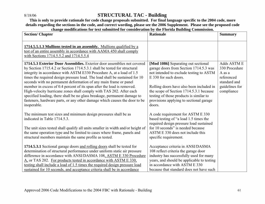
8/18/06 STRUCTURAL TAC - Building This is only to provide rationale for code change proposals submitted. For final language specific to the 2004 code, more
details regarding the sections in the code, and correct wording, please see the 2006 Supplement. Please see the proposed code change modifications for text submitted for consideration by the Florida Building Commission.
Approved 2006 Code Modifications to the 2004 FBC with Rationale - Building 61
Section/ Chapter
Rationale Summary
1714.5.5.1.3 Mullions tested in an assembly. Mullions qualified by a test of an entire assembly in accordance with AAMA 450 shall comply with Sections 1714.5.5.2 and 1714.5.5.4
1714.5.3 Exterior Door Assemblies. Exterior door assemblies not covered by Section 1715.4.2 or Section 1714.5.3.1 shall be tested for structural integrity in accordance with ASTM E330 Procedure A, at a load of 1.5 times the required design pressure load. The load shall be sustained for 10 seconds with no permanent deformation of any main frame or panel member in excess of 0.4 percent of its span after the load is removed. High-velocity hurricane zones shall comply with TAS 202. After each specified loading, there shall be no glass breakage, permanent damage to fasteners, hardware parts, or any other damage which causes the door to be inoperable. The minimum test sizes and minimum design pressures shall be as indicated in Table 1714.5.3. The unit sizes tested shall qualify all units smaller in width and/or height of the same operation type and be limited to cases where frame, panels and structural members maintain the same profile as tested. 1714.5.3.1 Sectional garage doors and rolling doors shall be tested for determination of structural performance under uniform static air pressure difference in accordance with ANSI/DASMA 108, ASTM E 330 Procedure A, or TAS 202. For products tested in accordance with ASTM E 330, testing shall include a load of 1.5 times the required design pressure load sustained for 10 seconds, and acceptance criteria shall be in accordance
[Mod 1086] Separating out sectional garage doors from Section 1714.5.3 was not intended to exclude testing to ASTM E 330 for such doors. Rolling doors have also been included in the scope of Section 1714.5.3.1 because testing of those products is similar to provisions applying to sectional garage doors. A code requirement for ASTM E 330 based testing of “a load 1.5 times the required design pressure load sustained for 10 seconds” is needed because ASTM E 330 does not include this specific requirement. Acceptance criteria in ANSI/DASMA 108 reflect criteria the garage door industry has successfully used for many years, and should be applicable to testing in accordance with ASTM E 330 because that standard does not have such
Adds ASTM E 330 Procedure A as a referenced standard and guidelines for compliance

8/18/06 STRUCTURAL TAC - Building This is only to provide rationale for code change proposals submitted. For final language specific to the 2004 code, more
details regarding the sections in the code, and correct wording, please see the 2006 Supplement. Please see the proposed code change modifications for text submitted for consideration by the Florida Building Commission.
Approved 2006 Code Modifications to the 2004 FBC with Rationale - Building 62
Section/ Chapter
Rationale Summary
with ANSI/DASMA 108. HVHZ shall comply with TAS 202. criteria. 1714.5.3.3.1 Glazed curtain wall, window wall and storefront systems shall be tested in accordance with the requirements of this section and the requirements of the American Architectural Aluminum Manufacturers Association (AAMA) Standard 501, HVHZ shall comply with 2411.3.2.1.1.
[Mod 1242] Requiring compliance to AAMA 501 as stated in section 1714.5.3.3.1 was meant to achieve compliance of glazed curtain wall, window wall and storefront systems with the intend of the code which, guarantees the health, safety and welfare of the general public. It was not intended, however, to raise the cost of commercial buildings by requiring mandatory field-testing. The proposed change will maintain the nationally recognized modus, whereby; the number and type of field tests is defined by contractual conditions between the commercial project developer and the fenestration product supplier.
Adds additional testing requirement
2002.2.1 Definitions PRIMARY MEMBER. Structural framing members providing structural support to other members and/or surfaces of a structure including, but not limited to beams, posts, columns, joists, structural gutters, headers, purlins etc. SECONDARY MEMBERS. Structural framing members which do not provide basic support for the entire structure, generally including, but not limited to, such members as kickplate rails, chair rails, roof or wall panels, etc. STRUCTURAL MEMBERS. Members or sections that provide support
[Mod 1906r] The proposal is a companion to the changes made to Table 2002.4 addressing items formerly addressed in the notes to the table and within the table.
Adds definitions for “primary member”, “secondary members”, and “structural members”; Deletes and replaces text in

8/18/06 STRUCTURAL TAC - Building This is only to provide rationale for code change proposals submitted. For final language specific to the 2004 code, more
details regarding the sections in the code, and correct wording, please see the 2006 Supplement. Please see the proposed code change modifications for text submitted for consideration by the Florida Building Commission.
Approved 2006 Code Modifications to the 2004 FBC with Rationale - Building 63
Section/ Chapter
Rationale Summary
of to an assembly and/or resist applied loads. 2002.3.2 Screen density shall be a maximum of 20X20 mesh. 2002.4 Design. Structural members supporting screen enclosures shall be designed to support minimum wind loads given in Table 2002.4. Where any value is less than 10 psf (479 Pa) use 10 psf. Loads. Structural members supporting screened enclosures shall be designed for wind in either of two orthogonal directions using the pressures given in Table 2002.4. Each primary member shall also be designed for a 300 lb (1.33 kN) load applied vertically downward along any 1 ft (0.3 m) of any member, not occurring simultaneously with wind load.
2002.4
TABLE 2002.4 DESIGN WIND PRESSURES FOR ALUMINUM SCREENED ENCLOSURES
WITH AN IMPORTANCE FACTOR OF 0.77{1,2,3} Basic Wind Speed (mph) 100 110 120 130 140 150 Load Case
Wall Surface
Exposure Category (B or C) Design Pressure (psf)
CB BC CB BC CB BC CB BC CB BC CB BC A4 Windward
and leeward walls (flow thru) and windward wall (non flow thru)
12 8 17
14 13
10 18
17 15
12 21
19 18
14 25
23 21
16 29
26 24
18 33
[Mod 1919] The table being modified is a Florida Specific amendment based on research done by Dr. Timothy Reinhold, P.E. and sponsored by the Aluminum Association of Florida, a contractor organization. In the aftermath of the storms of 2004 the Aluminum Association of Florida (AAF) as well as many others questioned the large number of screen enclosure failures where the reported wind speeds did not even approach the basic design wind speeds. We discovered a vast disparity in the engineering being used to erect such structures. One jurisdiction did a comparison of plans it had on file and
Revises Table 2002.4
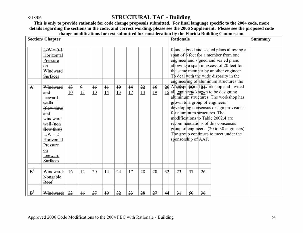
8/18/06 STRUCTURAL TAC - Building This is only to provide rationale for code change proposals submitted. For final language specific to the 2004 code, more
details regarding the sections in the code, and correct wording, please see the 2006 Supplement. Please see the proposed code change modifications for text submitted for consideration by the Florida Building Commission.
Approved 2006 Code Modifications to the 2004 FBC with Rationale - Building 64
Section/ Chapter
Rationale Summary
L/W = 0-1 Horizontal Pressure on Windward Surfaces
A4 Windward
and leeward walls (flow thru) and windward wall (non flow thru) L/W = 2 Horizontal Pressure on Leeward Surfaces
13 10
9 13
16 10
11 14
19 13
14 17
22 14
16 19
26 15
18 23
30 18
21 27
B5 Windward:
Nongable Roof
16 12 20 14 24 17 28 20 32 23 37 26
B5 Windward: 22 16 27 19 32 23 28 27 44 31 50 36
found signed and sealed plans allowing a span of 6 feet for a member from one engineer and signed and sealed plans allowing a span in excess of 20 feet for the same member by another engineer. To deal with the wide disparity in the engineering of aluminum structures the AAF sponsored a workshop and invited all engineers known to be designing aluminum structures. The workshop has grown to a group of engineers developing consensus design provisions for aluminum structures. The modifications to Table 2002.4 are recommendations of this consensus group of engineers (20 to 30 engineers). The group continues to meet under the sponsorship of AAF.

8/18/06 STRUCTURAL TAC - Building This is only to provide rationale for code change proposals submitted. For final language specific to the 2004 code, more
details regarding the sections in the code, and correct wording, please see the 2006 Supplement. Please see the proposed code change modifications for text submitted for consideration by the Florida Building Commission.
Approved 2006 Code Modifications to the 2004 FBC with Rationale - Building 65
Section/ Chapter
Rationale Summary
Gable Roof All6 Roof
screen Vertical Pressure – Screen Surfaces
4 3
3 5
5 4
4 5
6 4
4 6
7 5
5 7
8 6
6 8
9 7
7 9
All6 Roof Solid
Vertical Pressure – Solid Surfaces
12 10
9 14
15 11
11 15
18 13
13 18
21 15
15 21
24 17
17 24
28 20
20 28
NOTES: 1. Values have been reduced for 0.77 Importance Factor in accordance with Table 1606. Pressures include importance factors determined in accordance with Table 1604.5. 2. Minimum design pressure shall be 10 psf (479 Pa) in accordance with Section 1609.1.2. 2. Loads are applicable to screen Pressures apply to enclosures with a mean enclosure roof height of 30 feet (10 m) or less. For screen enclosures of different other heights, multiply the pressures in this table by the factors the pressures given shall be adjusted by multiplying the table pressure by the adjustment factor given in Table 2002.4A. 4. For Load Case A Flow-through condition the pressure given shall be applied simultaneously to both the upwind and downwind screen walls acting in the same direction. For the non-flow thru condition the screen enclosure wall shall be analyzed for the load applied acting toward the interior of the enclosure. . 5. For Load Case B the table pressure multiplied by the projected frontal area of the screen enclosure is the total drag force, including drag on screen surfaces parallel to the wind, which must be transmitted to the ground. Use Load Case A for members directly
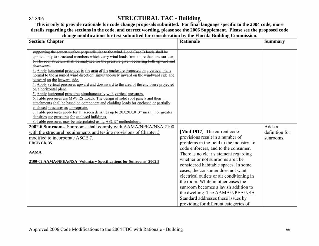
8/18/06 STRUCTURAL TAC - Building This is only to provide rationale for code change proposals submitted. For final language specific to the 2004 code, more
details regarding the sections in the code, and correct wording, please see the 2006 Supplement. Please see the proposed code change modifications for text submitted for consideration by the Florida Building Commission.
Approved 2006 Code Modifications to the 2004 FBC with Rationale - Building 66
Section/ Chapter
Rationale Summary
supporting the screen surface perpendicular to the wind. Load Case B loads shall be applied only to structural members which carry wind loads from more than one surface 6. The roof structure shall be analyzed for the pressure given occurring both upward and downward. 3. Apply horizontal pressures to the area of the enclosure projected on a vertical plane normal to the assumed wind direction, simultaneously inward on the windward side and outward on the leeward side. 4. Apply vertical pressures upward and downward to the area of the enclosure projected on a horizontal plane. 5. Apply horizontal pressures simultaneously with vertical pressures. 6. Table pressures are MWFRS Loads. The design of solid roof panels and their attachments shall be based on component and cladding loads for enclosed or partially enclosed structures as appropriate. 7. Table pressures apply for all screen densities up to 20X20X.013” mesh. For greater densities use pressures for enclosed buildings. 8. Table pressures may be interpolated using ASCE7 methodology.
2002.6 Sunrooms. Sunrooms shall comply with AAMA/NPEA/NSA 2100 with the structural requirements and testing provisions of Chapter 5 modified to incorporate ASCE 7. FBCB Ch. 35 AAMA 2100-02 AAMA/NPEA/NSA Voluntary Specifications for Sunrooms 2002.5
[Mod 1917] The current code provisions result in a number of problems in the field to the industry, to code enforcers, and to the consumer. There is no clear statement regarding whether or not sunrooms are t be considered habitable spaces. In some cases, the consumer does not want electrical outlets or air conditioning in the room. While in other cases the sunroom becomes a lavish addition to the dwelling. The AAMA/NPEA/NSA Standard addresses these issues by providing for different categories of
Adds a definition for sunrooms.

8/18/06 STRUCTURAL TAC - Building This is only to provide rationale for code change proposals submitted. For final language specific to the 2004 code, more
details regarding the sections in the code, and correct wording, please see the 2006 Supplement. Please see the proposed code change modifications for text submitted for consideration by the Florida Building Commission.
Approved 2006 Code Modifications to the 2004 FBC with Rationale - Building 67
Section/ Chapter
Rationale Summary
sunrooms. The proposal modifies the structural requirements and testing provisions of the standard to comply with changes made to the Florida Building Code in the 2005 Supplement. Approval of the proposal will permit more economical construction of sunrooms in Florida.
Increases in allowable unit stresses as set forth for wind loads in Section 1613 shall be applicable to aluminum structural members except that allowable unit stresses thus increased shall not exceed 75 percent of the minimum yield strength. Delete s. 2003.7.1 including exception
[Mod 1142r] Reference to Section 1613 is wrong which is for High Velocity Hurricane Zone Deflection. Original reference in Florida Building Code 2001 was to Section 1621 High Velocity Hurricane Zone Allowable Stress Increase which has been deleted in 2004 Code. The correct reference must be to Section 2.3 of Aluminum Design Manual ADM-1
Replaces reference to FBC Building Section 1613 with Section 2.3 of “Allowable Stress Design Specifications for Aluminum Structures of Aluminum Design Manual ADM-1”
2121.1.6 Minimum No. 9 gauge horizontal joint reinforcing at every alternate course (16 inches spacing), ladder type for reinforced masonry and truss type for all others shall be provided. This reinforcement shall extend 4 inches (102 mm) into tie columns or be tied to structural columns with approved methods where structural columns replace the tie columns.
[Mod 1369] The spacing for the horizontal reinforcement was missing. Standard for the industry is to provide horizontal reinforcement at least at every alternate course. By adding the spacing it completes the requirement.
Adds spacing requirement to text

8/18/06 STRUCTURAL TAC - Building This is only to provide rationale for code change proposals submitted. For final language specific to the 2004 code, more
details regarding the sections in the code, and correct wording, please see the 2006 Supplement. Please see the proposed code change modifications for text submitted for consideration by the Florida Building Commission.
Approved 2006 Code Modifications to the 2004 FBC with Rationale - Building 68
Section/ Chapter
Rationale Summary
2121.2.3.2 3. Beam block shall be reinforced with one # 7 bar in the top and one # 7 bar in the top bottom of the pour.
[Mod 1344] This is a simple correction of an error. Correct reinforcement should be one #7 at top and one # 7 at bottom instead of both # 7 bars at the top.
Editorial change
2107.2.3 ACI 530/ASCE 5/TMS 402, Section 2.1.10.7.1.1, lap splices. The minimum length of lap splices for reinforcing bars in tension or compression, lld, shall be calculated by Equation 21-2, but shall not be less than 15 inches (380 mm). lld = 0.002dbfs (Equation 21-2) For SI: lld = 0.29dbfs but not less than 12 inches (305 mm). In no case shall the length of the lapped splice be less than 40 bar diameters. where: db = Diameter of reinforcement, inches (mm). fs = Computed stress in reinforcement due to design loads, psi (MPa).
where: db = Diameter of reinforcement, inches (mm). fy = Specified yield stress of the reinforcement or the anchor bolt, psi (MPa). f' m = Specified compressive strength of masonry at age of 28 days, psi (MPa). lld = Minimum lap splice length, inches (mm). K = The lesser of the masonry cover, clear spacing between adjacent
[Mod 1828c] The new masonry code represents considerable improvement with respect to strength design resulting in more efficient use of masonry materials.
Updates standard.

8/18/06 STRUCTURAL TAC - Building This is only to provide rationale for code change proposals submitted. For final language specific to the 2004 code, more
details regarding the sections in the code, and correct wording, please see the 2006 Supplement. Please see the proposed code change modifications for text submitted for consideration by the Florida Building Commission.
Approved 2006 Code Modifications to the 2004 FBC with Rationale - Building 69
Section/ Chapter
Rationale Summary
reinforcement or five times db, inches (mm). = 1.0 for No. 3 through No. 5 reinforcing bars. 1.4 for No. 6 and No. 7 reinforcing bars. 1.5 for No. 8 through No. 9 reinforcing bars. In regions of moment where the design tensile stresses in the reinforcement are greater than 80 percent of the allowable steel tension stress Fs, the lap length of splices shall be increased not less than 50 percent of the minimum required length. Other equivalent means of stress transfer to accomplish the same 50 percent increase shall be permitted to be used. 2108.3 ACI 530/ASCE 5/TMS 402, Section 3.3.3.3. Modify Section 3.3.3.3 as follows: The required development length of reinforcement shall be determined by Eq. (3-15), but shall not be less than 12 in. (305 mm) and need not be greater than 72 db. 2108.3 2108.3.1 ACI American Concrete Institute 38800 Country Club Drive Farmington Hills, MI 48331 530/530.1-02 05 Building Code Requirements for Masonry Structures and Specifications for Masonry Structures & Commentaries 2211.2.1 Design shear determination. Where allowable stress design (ASD) is used, the allowable shear value shall be determined by dividing
[Mod 1183] The factor of safety and resistance factors were left out of the
Adds a factor of safety to
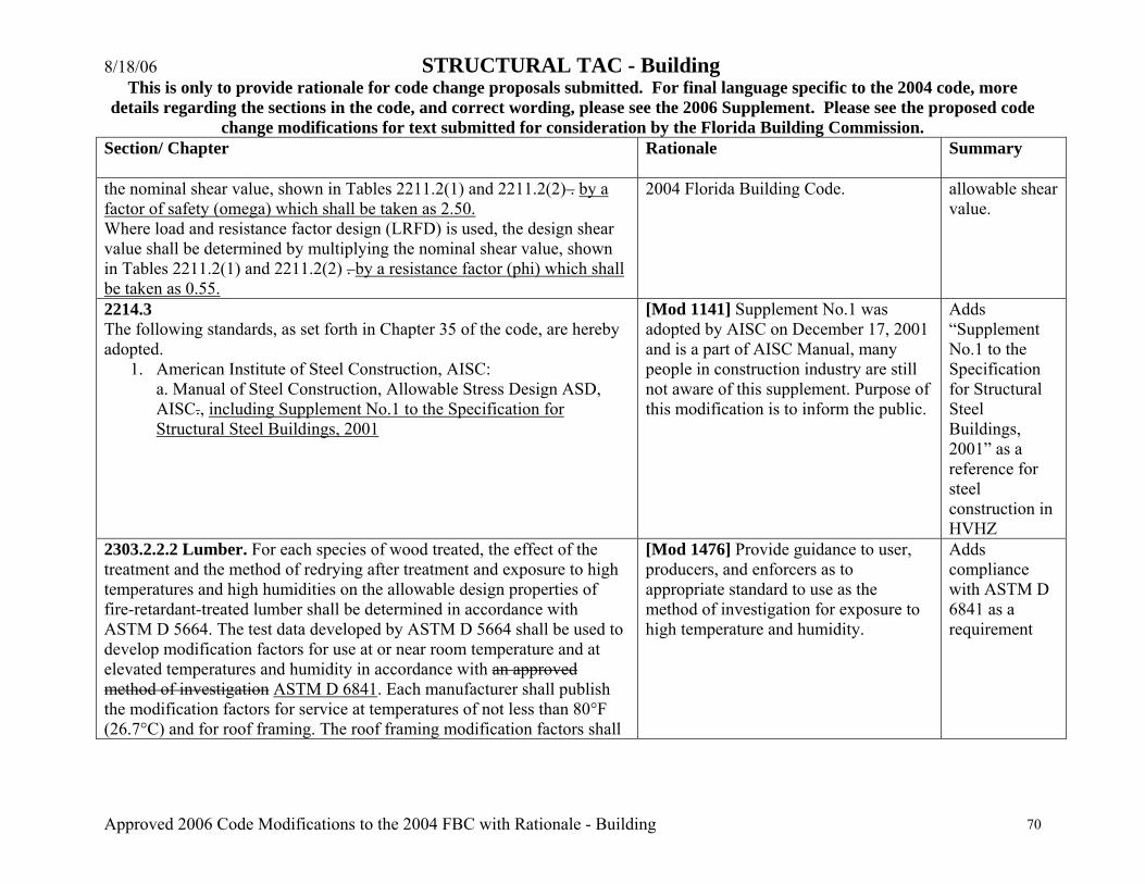
8/18/06 STRUCTURAL TAC - Building This is only to provide rationale for code change proposals submitted. For final language specific to the 2004 code, more
details regarding the sections in the code, and correct wording, please see the 2006 Supplement. Please see the proposed code change modifications for text submitted for consideration by the Florida Building Commission.
Approved 2006 Code Modifications to the 2004 FBC with Rationale - Building 70
Section/ Chapter
Rationale Summary
the nominal shear value, shown in Tables 2211.2(1) and 2211.2(2) . by a factor of safety (omega) which shall be taken as 2.50. Where load and resistance factor design (LRFD) is used, the design shear value shall be determined by multiplying the nominal shear value, shown in Tables 2211.2(1) and 2211.2(2) . by a resistance factor (phi) which shall be taken as 0.55.
2004 Florida Building Code.
allowable shear value.
2214.3 The following standards, as set forth in Chapter 35 of the code, are hereby adopted.
1. American Institute of Steel Construction, AISC: a. Manual of Steel Construction, Allowable Stress Design ASD, AISC., including Supplement No.1 to the Specification for Structural Steel Buildings, 2001
[Mod 1141] Supplement No.1 was adopted by AISC on December 17, 2001 and is a part of AISC Manual, many people in construction industry are still not aware of this supplement. Purpose of this modification is to inform the public.
Adds “Supplement No.1 to the Specification for Structural Steel Buildings, 2001” as a reference for steel construction in HVHZ
2303.2.2.2 Lumber. For each species of wood treated, the effect of the treatment and the method of redrying after treatment and exposure to high temperatures and high humidities on the allowable design properties of fire-retardant-treated lumber shall be determined in accordance with ASTM D 5664. The test data developed by ASTM D 5664 shall be used to develop modification factors for use at or near room temperature and at elevated temperatures and humidity in accordance with an approved method of investigation ASTM D 6841. Each manufacturer shall publish the modification factors for service at temperatures of not less than 80°F (26.7°C) and for roof framing. The roof framing modification factors shall
[Mod 1476] Provide guidance to user, producers, and enforcers as to appropriate standard to use as the method of investigation for exposure to high temperature and humidity.
Adds compliance with ASTM D 6841 as a requirement
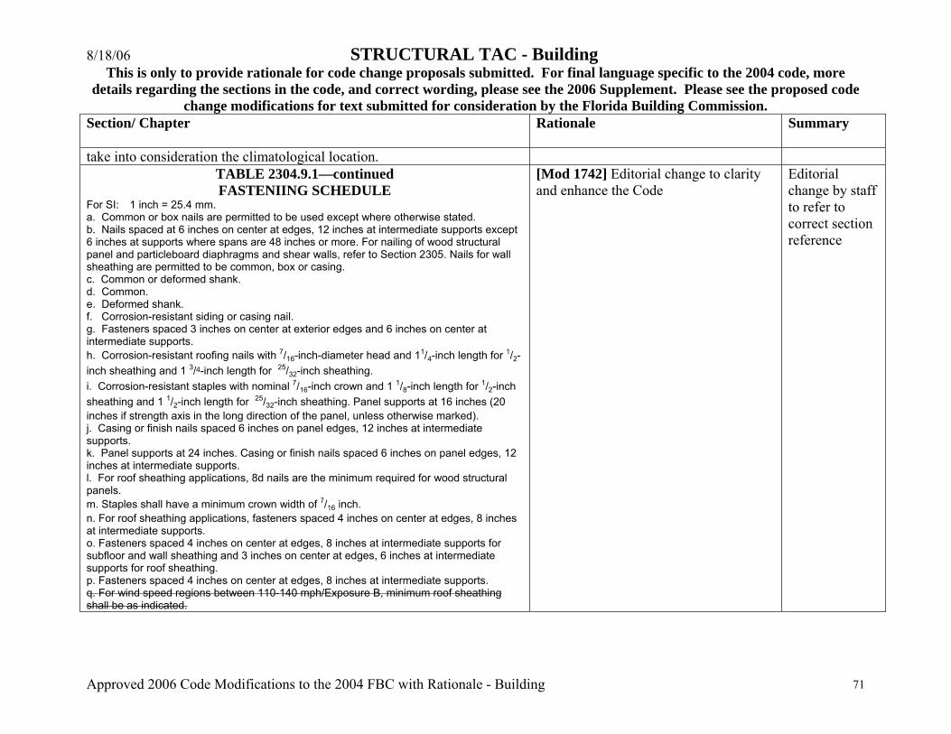
8/18/06 STRUCTURAL TAC - Building This is only to provide rationale for code change proposals submitted. For final language specific to the 2004 code, more
details regarding the sections in the code, and correct wording, please see the 2006 Supplement. Please see the proposed code change modifications for text submitted for consideration by the Florida Building Commission.
Approved 2006 Code Modifications to the 2004 FBC with Rationale - Building 71
Section/ Chapter
Rationale Summary
take into consideration the climatological location. TABLE 2304.9.1—continued FASTENIING SCHEDULE
For SI: 1 inch = 25.4 mm. a. Common or box nails are permitted to be used except where otherwise stated. b. Nails spaced at 6 inches on center at edges, 12 inches at intermediate supports except 6 inches at supports where spans are 48 inches or more. For nailing of wood structural panel and particleboard diaphragms and shear walls, refer to Section 2305. Nails for wall sheathing are permitted to be common, box or casing. c. Common or deformed shank. d. Common. e. Deformed shank. f. Corrosion-resistant siding or casing nail. g. Fasteners spaced 3 inches on center at exterior edges and 6 inches on center at intermediate supports. h. Corrosion-resistant roofing nails with 7/16-inch-diameter head and 11/4-inch length for 1/2-inch sheathing and 1 3/4-inch length for 25/32-inch sheathing. i. Corrosion-resistant staples with nominal 7/16-inch crown and 1 1/8-inch length for 1/2-inch sheathing and 1 1/2-inch length for 25/32-inch sheathing. Panel supports at 16 inches (20 inches if strength axis in the long direction of the panel, unless otherwise marked). j. Casing or finish nails spaced 6 inches on panel edges, 12 inches at intermediate supports. k. Panel supports at 24 inches. Casing or finish nails spaced 6 inches on panel edges, 12 inches at intermediate supports. l. For roof sheathing applications, 8d nails are the minimum required for wood structural panels. m. Staples shall have a minimum crown width of 7/16 inch. n. For roof sheathing applications, fasteners spaced 4 inches on center at edges, 8 inches at intermediate supports. o. Fasteners spaced 4 inches on center at edges, 8 inches at intermediate supports for subfloor and wall sheathing and 3 inches on center at edges, 6 inches at intermediate supports for roof sheathing. p. Fasteners spaced 4 inches on center at edges, 8 inches at intermediate supports. q. For wind speed regions between 110-140 mph/Exposure B, minimum roof sheathing shall be as indicated.
[Mod 1742] Editorial change to clarity and enhance the Code
Editorial change by staff to refer to correct section reference

8/18/06 STRUCTURAL TAC - Building This is only to provide rationale for code change proposals submitted. For final language specific to the 2004 code, more
details regarding the sections in the code, and correct wording, please see the 2006 Supplement. Please see the proposed code change modifications for text submitted for consideration by the Florida Building Commission.
Approved 2006 Code Modifications to the 2004 FBC with Rationale - Building 72
Section/ Chapter
Rationale Summary
2314.4.9 Truss Plate Institute. 583 D’Onofio Drive, Madison, WI 53719 TPI 218 N. Lee Street, Suite 312, Alexandria, VA 22314 1. National Design Standard for Metal Plate Connected Wood Truss Construction (Excluding Chapter 2). 2. Commentary and Recommendations for Handling, Installing and Bracing Metal Plate Connected Wood Trusses. (Excluding Chapter 13.2) HIB-91. Building Component Safety Information (BCSI 1-03) Guide to Good Practice for Handling, Installing & Bracing of Metal Plate Connected Wood Trusses [A joint publication with the Wood Truss Council of America (WTCA)]
[Mod 1258] HIB-91 is no longer published and this change merely updates the reference to the most current version of truss installation guidelines. The BCSI 1-03 information has been updated and is presented in a more graphical format. The references common to the International Residential Code (IRC) have been accepted by the ICC in the 2004/2005 code change cycle (RB-145) and will be included in the 2006 IRC. Copies of BCSI 1-03 were sent to DCA in February 2004 for review. The individual sections of BCSI 1-03 are also available in English/Spanish. They are designed for use by the erection/installation contractor. It is not the intent of these recommendations that they are superior to the project architect or engineer's bracing design specifications.
Replaces reference to HIB-91 with reference to BCSI 1-03 and corrects address for TPI
2319.17.2.4.1 All trusses shall be erected in accordance with Truss Plate Institute Manual Commentary and Recommendations for Handling & Bracing Metal Plate Connected Wood Trusses (HIB-91) TPI/WTCA BCSI 1-03 in addition to any requirements indicated on the approved permit document.
[Mod 1256] HIB-91 is no longer published and this change merely updates the reference to the most current version of truss installation guidelines. The BCSI 1-03 information has been updated and is presented in a more graphical format. The references
Replaces reference to HIB-91 with reference to BCSI 1-03
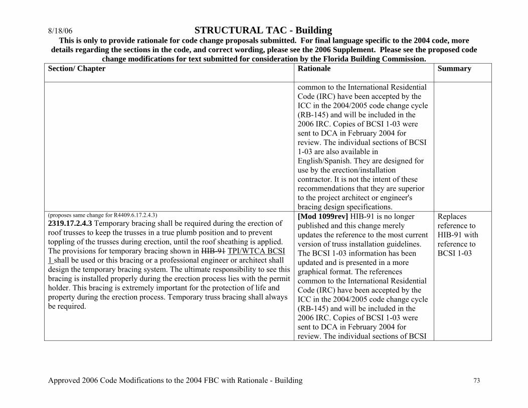
8/18/06 STRUCTURAL TAC - Building This is only to provide rationale for code change proposals submitted. For final language specific to the 2004 code, more
details regarding the sections in the code, and correct wording, please see the 2006 Supplement. Please see the proposed code change modifications for text submitted for consideration by the Florida Building Commission.
Approved 2006 Code Modifications to the 2004 FBC with Rationale - Building 73
Section/ Chapter
Rationale Summary
common to the International Residential Code (IRC) have been accepted by the ICC in the 2004/2005 code change cycle (RB-145) and will be included in the 2006 IRC. Copies of BCSI 1-03 were sent to DCA in February 2004 for review. The individual sections of BCSI 1-03 are also available in English/Spanish. They are designed for use by the erection/installation contractor. It is not the intent of these recommendations that they are superior to the project architect or engineer's bracing design specifications.
(proposes same change for R4409.6.17.2.4.3) 2319.17.2.4.3 Temporary bracing shall be required during the erection of roof trusses to keep the trusses in a true plumb position and to prevent toppling of the trusses during erection, until the roof sheathing is applied. The provisions for temporary bracing shown in HIB-91 TPI/WTCA BCSI 1 shall be used or this bracing or a professional engineer or architect shall design the temporary bracing system. The ultimate responsibility to see this bracing is installed properly during the erection process lies with the permit holder. This bracing is extremely important for the protection of life and property during the erection process. Temporary truss bracing shall always be required.
[Mod 1099rev] HIB-91 is no longer published and this change merely updates the reference to the most current version of truss installation guidelines. The BCSI 1-03 information has been updated and is presented in a more graphical format. The references common to the International Residential Code (IRC) have been accepted by the ICC in the 2004/2005 code change cycle (RB-145) and will be included in the 2006 IRC. Copies of BCSI 1-03 were sent to DCA in February 2004 for review. The individual sections of BCSI
Replaces reference to HIB-91 with reference to BCSI 1-03
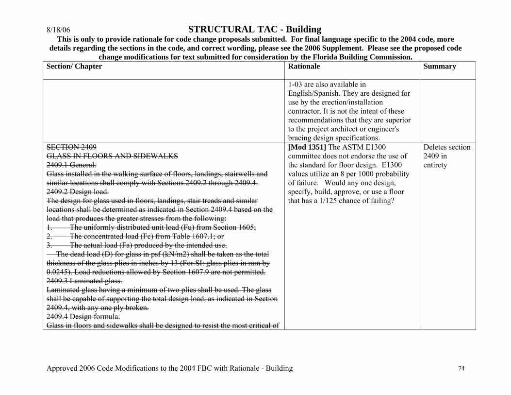
8/18/06 STRUCTURAL TAC - Building This is only to provide rationale for code change proposals submitted. For final language specific to the 2004 code, more
details regarding the sections in the code, and correct wording, please see the 2006 Supplement. Please see the proposed code change modifications for text submitted for consideration by the Florida Building Commission.
Approved 2006 Code Modifications to the 2004 FBC with Rationale - Building 74
Section/ Chapter
Rationale Summary
1-03 are also available in English/Spanish. They are designed for use by the erection/installation contractor. It is not the intent of these recommendations that they are superior to the project architect or engineer's bracing design specifications.
SECTION 2409 GLASS IN FLOORS AND SIDEWALKS 2409.1 General. Glass installed in the walking surface of floors, landings, stairwells and similar locations shall comply with Sections 2409.2 through 2409.4. 2409.2 Design load. The design for glass used in floors, landings, stair treads and similar locations shall be determined as indicated in Section 2409.4 based on the load that produces the greater stresses from the following: 1. The uniformly distributed unit load (Fu) from Section 1605; 2. The concentrated load (Fc) from Table 1607.1; or 3. The actual load (Fa) produced by the intended use. The dead load (D) for glass in psf (kN/m2) shall be taken as the total thickness of the glass plies in inches by 13 (For SI: glass plies in mm by 0.0245). Load reductions allowed by Section 1607.9 are not permitted. 2409.3 Laminated glass. Laminated glass having a minimum of two plies shall be used. The glass shall be capable of supporting the total design load, as indicated in Section 2409.4, with any one ply broken. 2409.4 Design formula. Glass in floors and sidewalks shall be designed to resist the most critical of
[Mod 1351] The ASTM E1300 committee does not endorse the use of the standard for floor design. E1300 values utilize an 8 per 1000 probability of failure. Would any one design, specify, build, approve, or use a floor that has a 1/125 chance of failing?
Deletes section 2409 in entirety
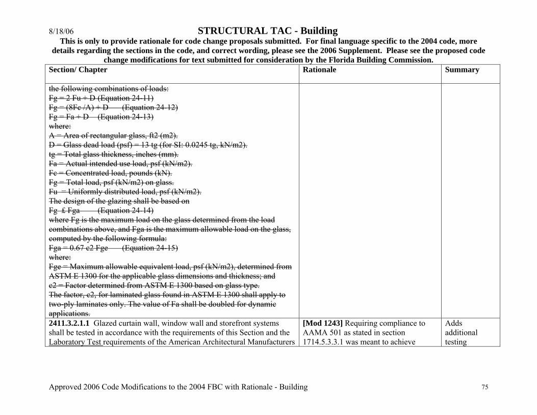
8/18/06 STRUCTURAL TAC - Building This is only to provide rationale for code change proposals submitted. For final language specific to the 2004 code, more
details regarding the sections in the code, and correct wording, please see the 2006 Supplement. Please see the proposed code change modifications for text submitted for consideration by the Florida Building Commission.
Approved 2006 Code Modifications to the 2004 FBC with Rationale - Building 75
Section/ Chapter
Rationale Summary
the following combinations of loads: Fg = 2 Fu + D (Equation 24-11) Fg = (8Fc /A) + D (Equation 24-12) Fg = Fa + D (Equation 24-13) where: A = Area of rectangular glass, ft2 (m2). D = Glass dead load (psf) = 13 tg (for SI: 0.0245 tg, kN/m2). tg = Total glass thickness, inches (mm). Fa = Actual intended use load, psf (kN/m2). Fc = Concentrated load, pounds (kN). Fg = Total load, psf (kN/m2) on glass. Fu = Uniformly distributed load, psf (kN/m2). The design of the glazing shall be based on Fg £ Fga (Equation 24-14) where Fg is the maximum load on the glass determined from the load combinations above, and Fga is the maximum allowable load on the glass, computed by the following formula: Fga = 0.67 c2 Fge (Equation 24-15) where: Fge = Maximum allowable equivalent load, psf (kN/m2), determined from ASTM E 1300 for the applicable glass dimensions and thickness; and c2 = Factor determined from ASTM E 1300 based on glass type. The factor, c2, for laminated glass found in ASTM E 1300 shall apply to two-ply laminates only. The value of Fa shall be doubled for dynamic applications. 2411.3.2.1.1 Glazed curtain wall, window wall and storefront systems shall be tested in accordance with the requirements of this Section and the Laboratory Test requirements of the American Architectural Manufacturers
[Mod 1243] Requiring compliance to AAMA 501 as stated in section 1714.5.3.3.1 was meant to achieve
Adds additional testing
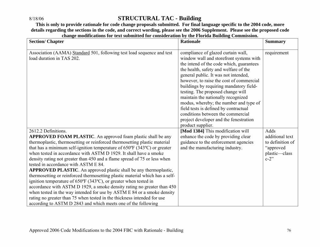
8/18/06 STRUCTURAL TAC - Building This is only to provide rationale for code change proposals submitted. For final language specific to the 2004 code, more
details regarding the sections in the code, and correct wording, please see the 2006 Supplement. Please see the proposed code change modifications for text submitted for consideration by the Florida Building Commission.
Approved 2006 Code Modifications to the 2004 FBC with Rationale - Building 76
Section/ Chapter
Rationale Summary
Association (AAMA) Standard 501, following test load sequence and test load duration in TAS 202.
compliance of glazed curtain wall, window wall and storefront systems with the intend of the code which, guarantees the health, safety and welfare of the general public. It was not intended, however, to raise the cost of commercial buildings by requiring mandatory field-testing. The proposed change will maintain the nationally recognized modus, whereby; the number and type of field tests is defined by contractual conditions between the commercial project developer and the fenestration product supplier.
requirement
2612.2 Definitions. APPROVED FOAM PLASTIC. An approved foam plastic shall be any thermoplastic, thermosetting or reinforced thermosetting plastic material that has a minimum self-ignition temperature of 650ºF (343ºC) or greater when tested in accordance with ASTM D 1929. It shall have a smoke density rating not greater than 450 and a flame spread of 75 or less when tested in accordance with ASTM E 84. APPROVED PLASTIC. An approved plastic shall be any thermoplastic, thermosetting or reinforced thermosetting plastic material which has a self-ignition temperature of 650ºF (343ºC), or greater when tested in accordance with ASTM D 1929, a smoke density rating no greater than 450 when tested in the way intended for use by ASTM E 84 or a smoke density rating no greater than 75 when tested in the thickness intended for use according to ASTM D 2843 and which meets one of the following
[Mod 1384] This modification will enhance the code by providing clear guidance to the enforcement agencies and the manufacturing industry.
Adds additional text to definition of “approved plastic—class c-2”
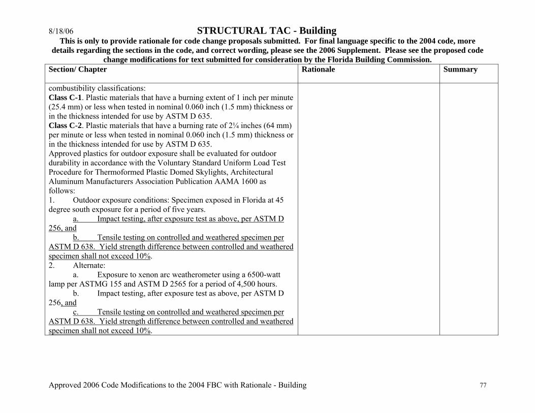
8/18/06 STRUCTURAL TAC - Building This is only to provide rationale for code change proposals submitted. For final language specific to the 2004 code, more
details regarding the sections in the code, and correct wording, please see the 2006 Supplement. Please see the proposed code change modifications for text submitted for consideration by the Florida Building Commission.
Approved 2006 Code Modifications to the 2004 FBC with Rationale - Building 77
Section/ Chapter
Rationale Summary
combustibility classifications: Class C-1. Plastic materials that have a burning extent of 1 inch per minute (25.4 mm) or less when tested in nominal 0.060 inch (1.5 mm) thickness or in the thickness intended for use by ASTM D 635. Class C-2. Plastic materials that have a burning rate of 2¼ inches (64 mm) per minute or less when tested in nominal 0.060 inch (1.5 mm) thickness or in the thickness intended for use by ASTM D 635. Approved plastics for outdoor exposure shall be evaluated for outdoor durability in accordance with the Voluntary Standard Uniform Load Test Procedure for Thermoformed Plastic Domed Skylights, Architectural Aluminum Manufacturers Association Publication AAMA 1600 as follows: 1. Outdoor exposure conditions: Specimen exposed in Florida at 45 degree south exposure for a period of five years. a. Impact testing, after exposure test as above, per ASTM D 256, and b. Tensile testing on controlled and weathered specimen per ASTM D 638. Yield strength difference between controlled and weathered specimen shall not exceed 10%. 2. Alternate: a. Exposure to xenon arc weatherometer using a 6500-watt lamp per ASTMG 155 and ASTM D 2565 for a period of 4,500 hours. b. Impact testing, after exposure test as above, per ASTM D 256, and c. Tensile testing on controlled and weathered specimen per ASTM D 638. Yield strength difference between controlled and weathered specimen shall not exceed 10%.

8/18/06 STRUCTURAL TAC - Building This is only to provide rationale for code change proposals submitted. For final language specific to the 2004 code, more
details regarding the sections in the code, and correct wording, please see the 2006 Supplement. Please see the proposed code change modifications for text submitted for consideration by the Florida Building Commission.
Approved 2006 Code Modifications to the 2004 FBC with Rationale - Building 78
Section/ Chapter
Rationale Summary
Section 2703 Cross Reference: Cross references Defining Electrical Requirements of the Florida Building Code. *This table is provided only as a tool to assist the construction industry as a general guide. User should review all sections of the code in order to determine specific applicable electrical requirements.
Florida Building Code 2004 Chapter 27 Electrical Systems Cross Reference Florida Building Code - Building Section Section Chapter 1 Administration Chapter 7 Fire-Resistance-Rated Construction
101 General 712 Penetrations 102 Applicability 714 Fire-Resistance Rating of Structural Members 105 Permits 715 Opening Protective 106 Construction Documents 716 Ducts and Air Transfer Openings 107 Temporary Structures and Uses 108 Fees Chapter 9 Fire Protection Systems 109 Inspections 901 General 111 Service Utilities 902 Definitions
903 Automatic Sprinkler Systems Chapter 2 Definitions 904 Alternative Automatic Fire-Extinguishing
202 Definitions Systems 907 Fire Alarm and Detection Systems
Chapter 3 Use and Occupancy Classification 908 Emergency Alarm Systems
[Mod 1275] The index points out other electrical requirements throughout the Florida building codes.
Adds cross references to electrical portions of the code.
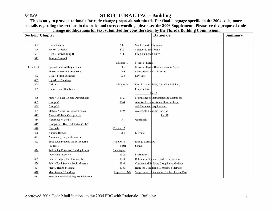
8/18/06 STRUCTURAL TAC - Building This is only to provide rationale for code change proposals submitted. For final language specific to the 2004 code, more
details regarding the sections in the code, and correct wording, please see the 2006 Supplement. Please see the proposed code change modifications for text submitted for consideration by the Florida Building Commission.
Approved 2006 Code Modifications to the 2004 FBC with Rationale - Building 79
Section/ Chapter
Rationale Summary
302 Classification 909 Smoke Control Systems 306 Factory Group F 910 Smoke and Heat Vents 307 High -Hazard Group H 911 Fire Command Center 311 Storage Group S
Chapter 10 Means of Egress Chapter 4 Special Detailed Requirement 1006 Means of Egress Illumination and Signs Based on Use and Occupancy 1008 Doors, Gates and Turnstiles
402 Covered Mall Buildings 1033 Day Care 403 High-Rise Buildings 404 Atriums Chapter 11 Florida Accessibility Code For Building 405 Underground Buildings Construction
Part A 406 Motor-Vehicle-Related Occupancies 11-3 Miscellaneous Instructions and Definitions 407 Group I-2 11-4 Accessible Elements and Spaces: Scope 408 Group I-3 and Technical Requirements 409 Motion Picture Projection Rooms 11-9 Accessible Transient Lodging 412 Aircraft-Related Occupancies Part B 414 Hazardous Materials 5 Guidelines 415 Groups H-1, H-2, H-3, H-4 and H-5 419 Hospitals Chapter 12 420 Nursing Homes 1205 Lighting 421 Ambulatory Surgical Centers 423 State Requirements for Educational Chapter 13 Energy Efficiency
Facilities 13-101 Scope 424 Swimming Pools and Bathing Places Subchapter
(Public and Private) 13-2 Definitions 425 Public Lodging Establishments 13-3 Referenced Standards and Organizations 426 Public Food Service Establishments 13-4 Commercial Building Compliance Methods 427 Mental Health Programs 13-6 Residential Building Compliance Methods 428 Manufactured Buildings Appendix 13-B Supplemental Information for Subchapter 13-4 431 Transient Public lodging Establishments
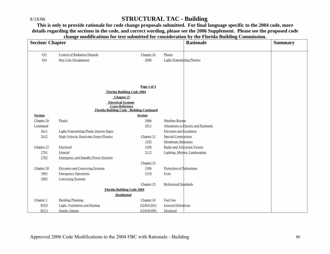
8/18/06 STRUCTURAL TAC - Building This is only to provide rationale for code change proposals submitted. For final language specific to the 2004 code, more
details regarding the sections in the code, and correct wording, please see the 2006 Supplement. Please see the proposed code change modifications for text submitted for consideration by the Florida Building Commission.
Approved 2006 Code Modifications to the 2004 FBC with Rationale - Building 80
Section/ Chapter
Rationale Summary
435 Control of Radiation Hazards Chapter 26 Plastic 436 Day Care Occupancies 2606 Light-Transmitting Plastics
Page 1 of 3 Florida Building Code 2004 Chapter 27 Electrical Systems Cross Reference Florida Building Code - Building Continued Section Section Chapter 26 Plastic 3006 Machine Rooms Continued 3011 Alterations to Electric and Hydraulic
2611 Light-Transmitting Plastic Interior Signs Elevators and Escalators 2612 High-Velocity Hurricane Zones-Plastics Chapter 31 Special Construction
3102 Membrane Structures Chapter 27 Electrical 3108 Radio and Television Towers
2701 General 3112 Lighting, Mirrors, Landscaping 2702 Emergency and Standby Power Systems
Chapter 33 Chapter 30 Elevators and Conveying Systems 3306 Protection of Pedestrians
3003 Emergency Operations 3310 Exits 3005 Conveying Systems
Chapter 35 Referenced Standards Florida Building Code 2004 Residential Chapter 3 Building Planning Chapter 24 Fuel Gas
R303 Light, Ventilation and Heating G2403(202) General Definitions R313 Smoke Alarms G2410(309) Electrical

8/18/06 STRUCTURAL TAC - Building This is only to provide rationale for code change proposals submitted. For final language specific to the 2004 code, more
details regarding the sections in the code, and correct wording, please see the 2006 Supplement. Please see the proposed code change modifications for text submitted for consideration by the Florida Building Commission.
Approved 2006 Code Modifications to the 2004 FBC with Rationale - Building 81
Section/ Chapter
Rationale Summary
R317 Dwelling Unit Separation G2411(310) Electrical Bonding G2440(615) Sauna Heaters
Chapter 8 Roof -Ceiling Construction R808 Insulation Clearance Chapter 33 General Requirements Electrical
E3301 General Requirements Electrical Chapter 13 General Mechanical System
Requirements Chapter 43 Referenced Standards M1303 Labeling of Equipment M1305 Appliance Access
Florida Building Code 2004
Florida Building Code - Existing Building Chapter 3 Chapter 11 Relocated or Moved Buildings
305 Alteration-Level 3 1102 Requirements
Chapter 4 Repairs Chapter 12 Compliance Alternatives 401 General 1201 General 408 Electrical
Chapter 14 Referenced Standards Chapter 5 Alterations Level 1
508 Electrical Appendix B Standard for Rehabilitation
Chapter 6 Alterations Level 2 608 Electrical
Chapter 8 Change of Occupancy
808 Electrical 811 Other Requirements
Chapter 9 Additions
901 General
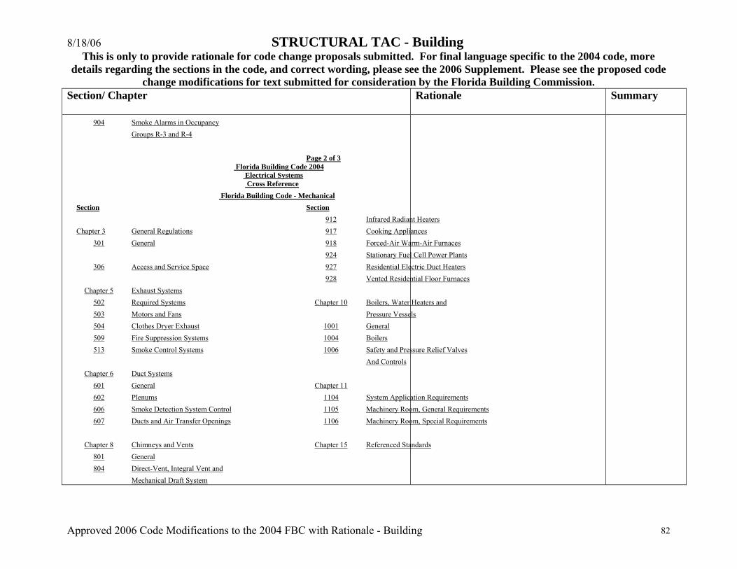
8/18/06 STRUCTURAL TAC - Building This is only to provide rationale for code change proposals submitted. For final language specific to the 2004 code, more
details regarding the sections in the code, and correct wording, please see the 2006 Supplement. Please see the proposed code change modifications for text submitted for consideration by the Florida Building Commission.
Approved 2006 Code Modifications to the 2004 FBC with Rationale - Building 82
Section/ Chapter
Rationale Summary
904 Smoke Alarms in Occupancy Groups R-3 and R-4 Page 2 of 3
Florida Building Code 2004 Electrical Systems Cross Reference
Florida Building Code - Mechanical Section Section 912 Infrared Radiant Heaters Chapter 3 General Regulations 917 Cooking Appliances
301 General 918 Forced-Air Warm-Air Furnaces 924 Stationary Fuel Cell Power Plants
306 Access and Service Space 927 Residential Electric Duct Heaters 928 Vented Residential Floor Furnaces
Chapter 5 Exhaust Systems 502 Required Systems Chapter 10 Boilers, Water Heaters and 503 Motors and Fans Pressure Vessels 504 Clothes Dryer Exhaust 1001 General 509 Fire Suppression Systems 1004 Boilers 513 Smoke Control Systems 1006 Safety and Pressure Relief Valves
And Controls Chapter 6 Duct Systems
601 General Chapter 11 602 Plenums 1104 System Application Requirements 606 Smoke Detection System Control 1105 Machinery Room, General Requirements 607 Ducts and Air Transfer Openings 1106 Machinery Room, Special Requirements
Chapter 8 Chimneys and Vents Chapter 15 Referenced Standards
801 General 804 Direct-Vent, Integral Vent and
Mechanical Draft System
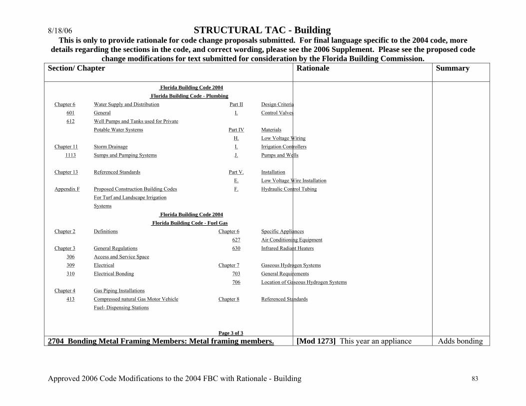
8/18/06 STRUCTURAL TAC - Building This is only to provide rationale for code change proposals submitted. For final language specific to the 2004 code, more
details regarding the sections in the code, and correct wording, please see the 2006 Supplement. Please see the proposed code change modifications for text submitted for consideration by the Florida Building Commission.
Approved 2006 Code Modifications to the 2004 FBC with Rationale - Building 83
Section/ Chapter
Rationale Summary
Florida Building Code 2004 Florida Building Code - Plumbing Chapter 6 Water Supply and Distribution Part II Design Criteria
601 General I. Control Valves 612 Well Pumps and Tanks used for Private
Potable Water Systems Part IV Materials H. Low Voltage Wiring Chapter 11 Storm Drainage I. Irrigation Controllers
1113 Sumps and Pumping Systems J. Pumps and Wells Chapter 13 Referenced Standards Part V. Installation E. Low Voltage Wire Installation Appendix F Proposed Construction Building Codes F. Hydraulic Control Tubing For Turf and Landscape Irrigation Systems Florida Building Code 2004 Florida Building Code - Fuel Gas Chapter 2 Definitions Chapter 6 Specific Appliances 627 Air Conditioning Equipment Chapter 3 General Regulations 630 Infrared Radiant Heaters
306 Access and Service Space 309 Electrical Chapter 7 Gaseous Hydrogen Systems 310 Electrical Bonding 703 General Requirements
706 Location of Gaseous Hydrogen Systems Chapter 4 Gas Piping Installations
413 Compressed natural Gas Motor Vehicle Chapter 8 Referenced Standards Fuel- Dispensing Stations Page 3 of 3
2704 Bonding Metal Framing Members: Metal framing members. [Mod 1273] This year an appliance Adds bonding
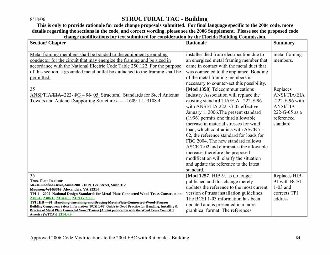
8/18/06 STRUCTURAL TAC - Building This is only to provide rationale for code change proposals submitted. For final language specific to the 2004 code, more
details regarding the sections in the code, and correct wording, please see the 2006 Supplement. Please see the proposed code change modifications for text submitted for consideration by the Florida Building Commission.
Approved 2006 Code Modifications to the 2004 FBC with Rationale - Building 84
Section/ Chapter
Rationale Summary
Metal framing members shall be bonded to the equipment grounding conductor for the circuit that may energize the framing and be sized in accordance with the National Electric Code Table 250.122. For the purpose of this section, a grounded metal outlet box attached to the framing shall be permitted.
installer died from electrocution due to an energized metal framing member that came in contact with the metal duct that was connected to the appliance. Bonding of the metal framing members is necessary to counter-act this possibility.
metal framing members.
35 ANSI/TIA/EIA- 222- FG – 96 05 Structural Standards for Steel Antenna Towers and Antenna Supporting Structures------1609.1.1, 3108.4
[Mod 1358] Telecommunications Industry Association will replace the existing standard TIA/EIA –222-F-96 with ANSI/TIA 222- G-05 effective January 1, 2006.The present standard (1996) permits one third allowable increase in material stresses for wind load, which contradicts with ASCE 7 –02, the reference standard for loads for FBC 2004. The new standard follows ASCE 7-02 and eliminates the allowable increase, therefore the proposed modification will clarify the situation and update the reference to the latest standard.
Replaces ANSI/TIA/EIA-222-F-96 with ANSI/TIA-222-G-05 as a referenced standard
35 Truss Plate Institute 583 D’Onofrio Drive, Suite 200 218 N. Lee Street, Suite 312 Madison, WI 53719 Alexandria, VA 22314 TPI 1—2002 National Design Standards for Metal-Plate-Connected Wood Truss Construction 2303.4 , 2306.1 , 2314.4.9 , 2319.17.2.1.1 , TPI HIB —91 Handling, Installing and Bracing Metal Plate Connected Wood Trusses Building Component Safety Information (BCSI 1-03) Guide to Good Practice for Handling, Installing & Bracing of Metal Plate Connected Wood Trusses [A joint publication with the Wood Truss Council of America (WTCA)] 2314.4.9
[Mod 1257] HIB-91 is no longer published and this change merely updates the reference to the most current version of truss installation guidelines. The BCSI 1-03 information has been updated and is presented in a more graphical format. The references
Replaces HIB-91 with BCSI 1-03 and corrects TPI address
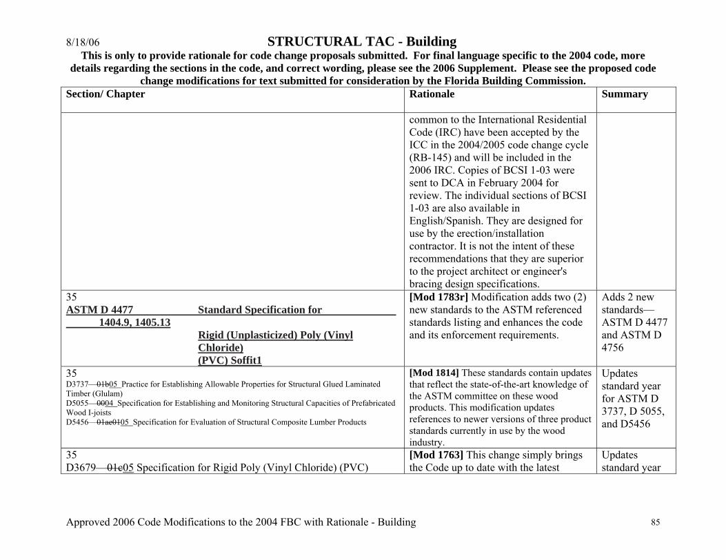
8/18/06 STRUCTURAL TAC - Building This is only to provide rationale for code change proposals submitted. For final language specific to the 2004 code, more
details regarding the sections in the code, and correct wording, please see the 2006 Supplement. Please see the proposed code change modifications for text submitted for consideration by the Florida Building Commission.
Approved 2006 Code Modifications to the 2004 FBC with Rationale - Building 85
Section/ Chapter
Rationale Summary
common to the International Residential Code (IRC) have been accepted by the ICC in the 2004/2005 code change cycle (RB-145) and will be included in the 2006 IRC. Copies of BCSI 1-03 were sent to DCA in February 2004 for review. The individual sections of BCSI 1-03 are also available in English/Spanish. They are designed for use by the erection/installation contractor. It is not the intent of these recommendations that they are superior to the project architect or engineer's bracing design specifications.
35 ASTM D 4477 Standard Specification for 1404.9, 1405.13
Rigid (Unplasticized) Poly (Vinyl Chloride) (PVC) Soffit1
[Mod 1783r] Modification adds two (2) new standards to the ASTM referenced standards listing and enhances the code and its enforcement requirements.
Adds 2 new standards—ASTM D 4477 and ASTM D 4756
35 D3737—01b05 Practice for Establishing Allowable Properties for Structural Glued Laminated Timber (Glulam) D5055—0004 Specification for Establishing and Monitoring Structural Capacities of Prefabricated Wood I-joists D5456—01ae0105 Specification for Evaluation of Structural Composite Lumber Products
[Mod 1814] These standards contain updates that reflect the state-of-the-art knowledge of the ASTM committee on these wood products. This modification updates references to newer versions of three product standards currently in use by the wood industry.
Updates standard year for ASTM D 3737, D 5055, and D5456
35 D3679—01c05 Specification for Rigid Poly (Vinyl Chloride) (PVC)
[Mod 1763] This change simply brings the Code up to date with the latest
Updates standard year
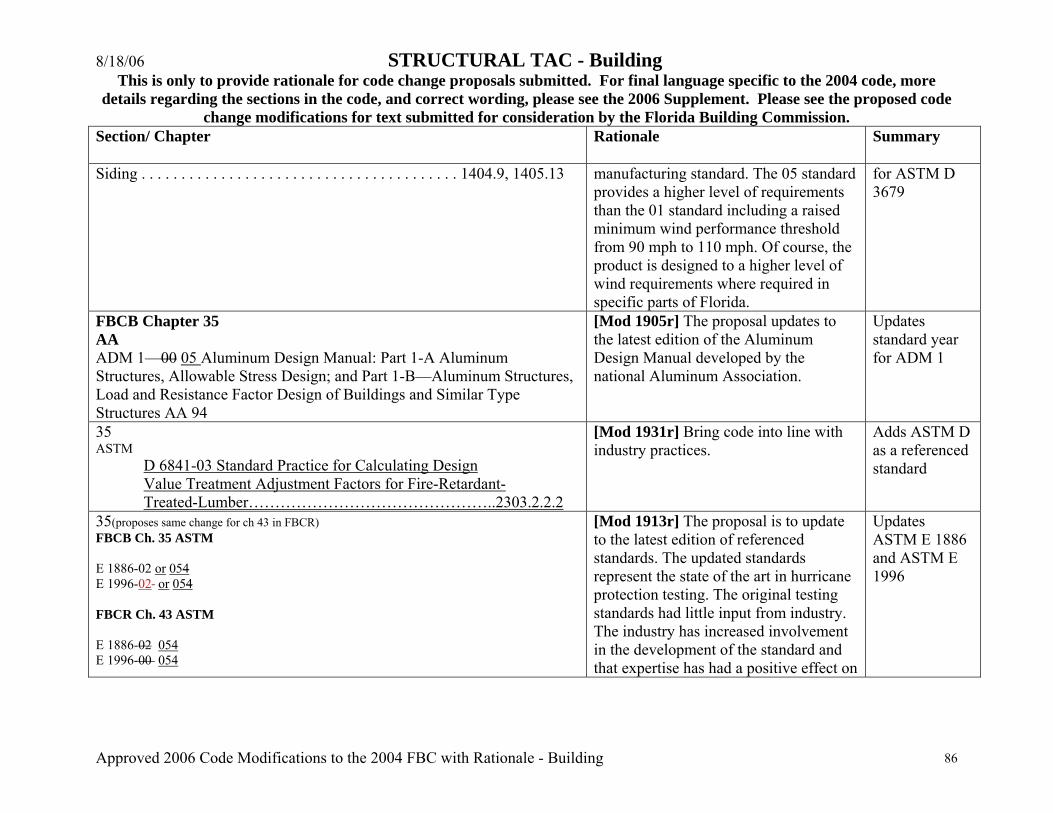
8/18/06 STRUCTURAL TAC - Building This is only to provide rationale for code change proposals submitted. For final language specific to the 2004 code, more
details regarding the sections in the code, and correct wording, please see the 2006 Supplement. Please see the proposed code change modifications for text submitted for consideration by the Florida Building Commission.
Approved 2006 Code Modifications to the 2004 FBC with Rationale - Building 86
Section/ Chapter
Rationale Summary
Siding . . . . . . . . . . . . . . . . . . . . . . . . . . . . . . . . . . . . . . . . 1404.9, 1405.13 manufacturing standard. The 05 standard provides a higher level of requirements than the 01 standard including a raised minimum wind performance threshold from 90 mph to 110 mph. Of course, the product is designed to a higher level of wind requirements where required in specific parts of Florida.
for ASTM D 3679
FBCB Chapter 35 AA ADM 1—00 05 Aluminum Design Manual: Part 1-A Aluminum Structures, Allowable Stress Design; and Part 1-B—Aluminum Structures, Load and Resistance Factor Design of Buildings and Similar Type Structures AA 94
[Mod 1905r] The proposal updates to the latest edition of the Aluminum Design Manual developed by the national Aluminum Association.
Updates standard year for ADM 1
35 ASTM
D 6841-03 Standard Practice for Calculating Design Value Treatment Adjustment Factors for Fire-Retardant- Treated-Lumber………………………………………..2303.2.2.2
[Mod 1931r] Bring code into line with industry practices.
Adds ASTM D as a referenced standard
35(proposes same change for ch 43 in FBCR) FBCB Ch. 35 ASTM E 1886-02 or 054 E 1996-02 or 054 FBCR Ch. 43 ASTM E 1886-02 054 E 1996-00 054
[Mod 1913r] The proposal is to update to the latest edition of referenced standards. The updated standards represent the state of the art in hurricane protection testing. The original testing standards had little input from industry. The industry has increased involvement in the development of the standard and that expertise has had a positive effect on
Updates ASTM E 1886 and ASTM E 1996
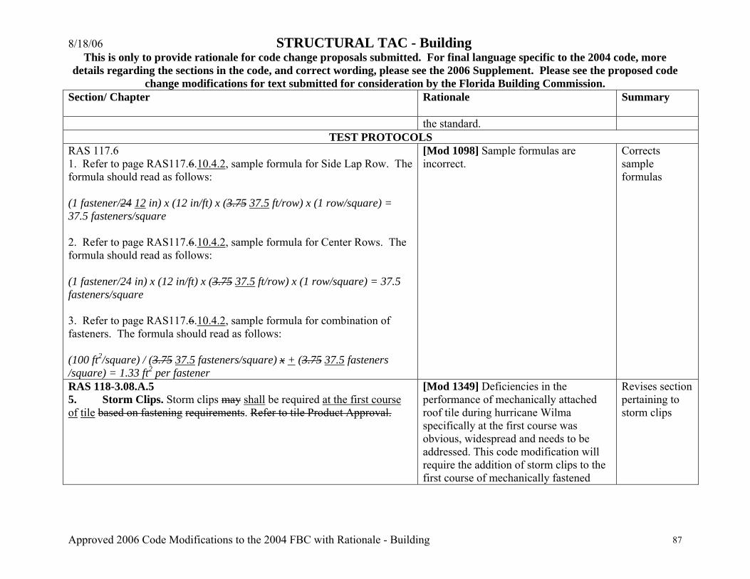
8/18/06 STRUCTURAL TAC - Building This is only to provide rationale for code change proposals submitted. For final language specific to the 2004 code, more
details regarding the sections in the code, and correct wording, please see the 2006 Supplement. Please see the proposed code change modifications for text submitted for consideration by the Florida Building Commission.
Approved 2006 Code Modifications to the 2004 FBC with Rationale - Building 87
Section/ Chapter
Rationale Summary
the standard. TEST PROTOCOLS
RAS 117.6 1. Refer to page RAS117.6.10.4.2, sample formula for Side Lap Row. The formula should read as follows: (1 fastener/24 12 in) x (12 in/ft) x (3.75 37.5 ft/row) x (1 row/square) = 37.5 fasteners/square 2. Refer to page RAS117.6.10.4.2, sample formula for Center Rows. The formula should read as follows: (1 fastener/24 in) x (12 in/ft) x (3.75 37.5 ft/row) x (1 row/square) = 37.5 fasteners/square 3. Refer to page RAS117.6.10.4.2, sample formula for combination of fasteners. The formula should read as follows: (100 ft2/square) / (3.75 37.5 fasteners/square) x + (3.75 37.5 fasteners /square) = 1.33 ft2 per fastener
[Mod 1098] Sample formulas are incorrect.
Corrects sample formulas
RAS 118-3.08.A.5 5. Storm Clips. Storm clips may shall be required at the first course of tile based on fastening requirements. Refer to tile Product Approval.
[Mod 1349] Deficiencies in the performance of mechanically attached roof tile during hurricane Wilma specifically at the first course was obvious, widespread and needs to be addressed. This code modification will require the addition of storm clips to the first course of mechanically fastened
Revises section pertaining to storm clips

8/18/06 STRUCTURAL TAC - Building This is only to provide rationale for code change proposals submitted. For final language specific to the 2004 code, more
details regarding the sections in the code, and correct wording, please see the 2006 Supplement. Please see the proposed code change modifications for text submitted for consideration by the Florida Building Commission.
Approved 2006 Code Modifications to the 2004 FBC with Rationale - Building 88
Section/ Chapter
Rationale Summary
roof tile to deal with this problem and strengthen the current code.
R119-3.09B. Fasten and secure maximum 24 in. on center with screws or fasteners of sufficient length to penetrate the sheathing a minimum of 3/4 in. or to penetrate into a 1 in., or greater, thickness of lumber not less than 1 in.
[Mod 1091] This is a glitch modification necessary to correct the omission of the word “or”. The current language would restrict the type of fastener to a “screw”. The specific application was tested with common nails (the lesser attachment) with the intention being that if the attachment test was successful with nails, then either nails or screws would be an acceptable fastener.
Editorial change
RAS 119-3.10 B. Storm Clips. Storm clips may shall be required at the first
course of tile based on fastening requirements. Refer to tile Product Approval.
[Mod 1350] Deficiencies in the performance of mechanically attached roof tile during hurricane Wilma specifically at the first course was obvious, widespread and needs to be addressed. This code modification will require the addition of storm clips to the first course of mechanically fastened roof tile to deal with this problem and strengthen the current code.
Revises section pertaining to storm clips
RAS 120 3.10 Hip and Ridge Installation - CHOOSE ONE of the following: A. Set hip and ridge tile in a continuous bed of mortar, lapping tile a minimum 2 in. Ensure bed of mortar does not protrude in center of hip or ridge junction. Approximately 1 in. of field tile shall extend beyond bed of mortar.
[Mod 1280] Across the State of Florida throughout the 2004 and current 2005 hurricane seasons the substandard performance of roofing hip and ridge tile attachment installed exclusively with mortar has become evident. Currently in
Revises section pertaining to hip and ridge installation
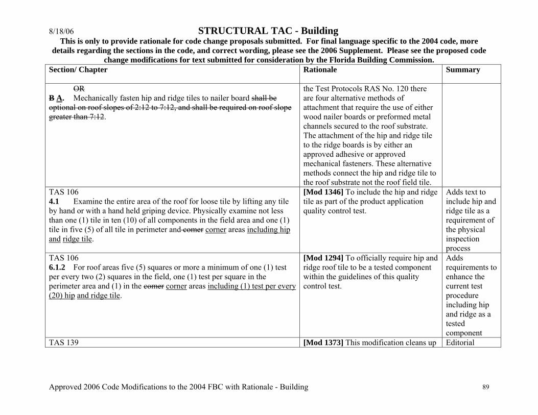
8/18/06 STRUCTURAL TAC - Building This is only to provide rationale for code change proposals submitted. For final language specific to the 2004 code, more
details regarding the sections in the code, and correct wording, please see the 2006 Supplement. Please see the proposed code change modifications for text submitted for consideration by the Florida Building Commission.
Approved 2006 Code Modifications to the 2004 FBC with Rationale - Building 89
Section/ Chapter
Rationale Summary
OR B A. Mechanically fasten hip and ridge tiles to nailer board shall be optional on roof slopes of 2:12 to 7:12, and shall be required on roof slope greater than 7:12.
the Test Protocols RAS No. 120 there are four alternative methods of attachment that require the use of either wood nailer boards or preformed metal channels secured to the roof substrate. The attachment of the hip and ridge tile to the ridge boards is by either an approved adhesive or approved mechanical fasteners. These alternative methods connect the hip and ridge tile to the roof substrate not the roof field tile.
TAS 106 4.1 Examine the entire area of the roof for loose tile by lifting any tile by hand or with a hand held griping device. Physically examine not less than one (1) tile in ten (10) of all components in the field area and one (1) tile in five (5) of all tile in perimeter and comer corner areas including hip and ridge tile.
[Mod 1346] To include the hip and ridge tile as part of the product application quality control test.
Adds text to include hip and ridge tile as a requirement of the physical inspection process
TAS 106 6.1.2 For roof areas five (5) squares or more a minimum of one (1) test per every two (2) squares in the field, one (1) test per square in the perimeter area and (1) in the comer corner areas including (1) test per every (20) hip and ridge tile.
[Mod 1294] To officially require hip and ridge roof tile to be a tested component within the guidelines of this quality control test.
Adds requirements to enhance the current test procedure including hip and ridge as a tested component
TAS 139 [Mod 1373] This modification cleans up Editorial
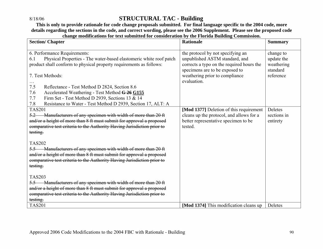
8/18/06 STRUCTURAL TAC - Building This is only to provide rationale for code change proposals submitted. For final language specific to the 2004 code, more
details regarding the sections in the code, and correct wording, please see the 2006 Supplement. Please see the proposed code change modifications for text submitted for consideration by the Florida Building Commission.
Approved 2006 Code Modifications to the 2004 FBC with Rationale - Building 90
Section/ Chapter
Rationale Summary
6. Performance Requirements: 6.1 Physical Properties - The water-based elastomeric white roof patch product shall conform to physical property requirements as follows: 7. Test Methods: … 7.5 Reflectance - Test Method D 2824, Section 8.6 7.6 Accelerated Weathering - Test Method G 26 G155 7.7 Firm Set - Test Method D 2939, Sections 13 & 14 7.8 Resistance to Water - Test Method D 2939, Section 17, ALT: A
the protocol by not specifying an unpublished ASTM standard, and corrects a typo on the required hours the specimens are to be exposed to weathering prior to compliance evaluation.
change to update the weathering standard reference
TAS201 5.2 Manufacturers of any specimen with width of more than 20 ft and/or a height of more than 8 ft must submit for approval a proposed comparative test criteria to the Authority Having Jurisdiction prior to testing. TAS202 5.5 Manufacturers of any specimen with width of more than 20 ft and/or a height of more than 8 ft must submit for approval a proposed comparative test criteria to the Authority Having Jurisdiction prior to testing. TAS203 5.5 Manufacturers of any specimen with width of more than 20 ft and/or a height of more than 8 ft must submit for approval a proposed comparative test criteria to the Authority Having Jurisdiction prior to testing.
[Mod 1377] Deletion of this requirement cleans up the protocol, and allows for a better representative specimen to be tested.
Deletes sections in entirety
TAS201 [Mod 1374] This modification cleans up Deletes
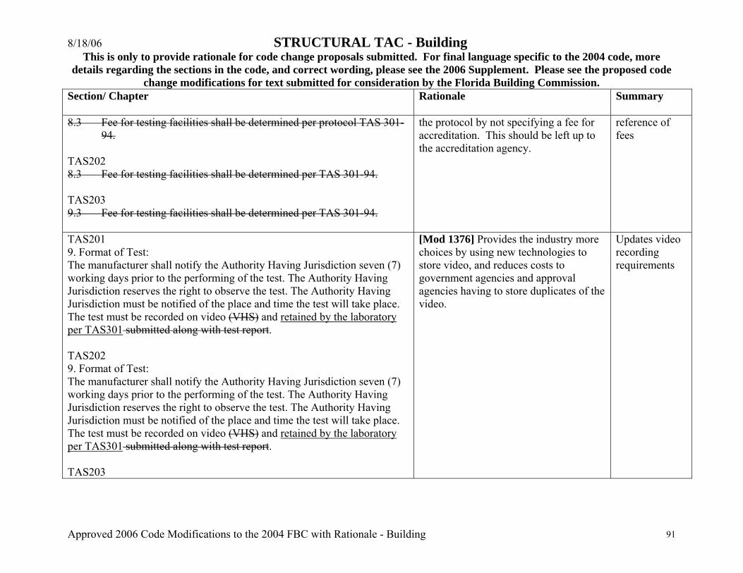
8/18/06 STRUCTURAL TAC - Building This is only to provide rationale for code change proposals submitted. For final language specific to the 2004 code, more
details regarding the sections in the code, and correct wording, please see the 2006 Supplement. Please see the proposed code change modifications for text submitted for consideration by the Florida Building Commission.
Approved 2006 Code Modifications to the 2004 FBC with Rationale - Building 91
Section/ Chapter
Rationale Summary
8.3 Fee for testing facilities shall be determined per protocol TAS 301-94.
TAS202 8.3 Fee for testing facilities shall be determined per TAS 301-94. TAS203 9.3 Fee for testing facilities shall be determined per TAS 301-94.
the protocol by not specifying a fee for accreditation. This should be left up to the accreditation agency.
reference of fees
TAS201 9. Format of Test: The manufacturer shall notify the Authority Having Jurisdiction seven (7) working days prior to the performing of the test. The Authority Having Jurisdiction reserves the right to observe the test. The Authority Having Jurisdiction must be notified of the place and time the test will take place. The test must be recorded on video (VHS) and retained by the laboratory per TAS301 submitted along with test report. TAS202 9. Format of Test: The manufacturer shall notify the Authority Having Jurisdiction seven (7) working days prior to the performing of the test. The Authority Having Jurisdiction reserves the right to observe the test. The Authority Having Jurisdiction must be notified of the place and time the test will take place. The test must be recorded on video (VHS) and retained by the laboratory per TAS301 submitted along with test report. TAS203
[Mod 1376] Provides the industry more choices by using new technologies to store video, and reduces costs to government agencies and approval agencies having to store duplicates of the video.
Updates video recording requirements

8/18/06 STRUCTURAL TAC - Building This is only to provide rationale for code change proposals submitted. For final language specific to the 2004 code, more
details regarding the sections in the code, and correct wording, please see the 2006 Supplement. Please see the proposed code change modifications for text submitted for consideration by the Florida Building Commission.
Approved 2006 Code Modifications to the 2004 FBC with Rationale - Building 92
Section/ Chapter
Rationale Summary
10. Format of Test: The manufacturer shall notify the Authority Having Jurisdiction seven (7) working days prior to the performing of the test. The Authority Having Jurisdiction reserves the right to observe the test. The Authority Having Jurisdiction must be notified of the place and time the test will take place. The test must be recorded on video (VHS) and retained by the laboratory per TAS301 submitted along with test report. TAS 202-12.1 12. Additional Testing: 12.1 After successfully completing all parts of the test described in this protocol, the specimen shall be subjected to the forced entry test per ASTM F588, ASTM F842, and AAMA 1304 as applicable. as required by Section 1707.4.2 of the Florida Building Code, Building. Minimum gauge of materials shall be determined prior to testing per Section 1707.4.2 of the Florida Building Code, Building. 12.2 Any product when installed that is subjected to weathering, where such weathering can affect the integrity of the product, the manufacturer shall contact the Authority Having Jurisdiction for additional testing requirements such as but not limited to moisture, U.V., accelerated aging, and other similar tests. 12.3 The Authority Having Jurisdiction reserves the right to require any additional testing necessary to assure full compliance with the intent of the Florida Building Code, Building.
[Mod 1379r] It would clearly document the requirement with what is actually occurring. Manufacturers are testing to these forced entry standards when complying with TAS202.
Replaces forced entry test compliance requirements
TAS 301 6. Submittals: 6.1 Name, address, contact person and telephone number of testing facility. 6.2 Name and registration number of Florida-Registered Professional
[Mod 1375] This modification cleans up the protocol by not specifying a fee for accreditation. This should be left up to the accreditation agency. The change is complemented with independence
Adds independence requirements and deletes reference to
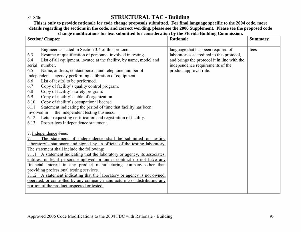
8/18/06 STRUCTURAL TAC - Building This is only to provide rationale for code change proposals submitted. For final language specific to the 2004 code, more
details regarding the sections in the code, and correct wording, please see the 2006 Supplement. Please see the proposed code change modifications for text submitted for consideration by the Florida Building Commission.
Approved 2006 Code Modifications to the 2004 FBC with Rationale - Building 93
Section/ Chapter
Rationale Summary
Engineer as stated in Section 3.4 of this protocol. 6.3 Resume of qualification of personnel involved in testing. 6.4 List of all equipment, located at the facility, by name, model and serial number. 6.5 Name, address, contact person and telephone number of independent agency performing calibration of equipment. 6.6 List of test(s) to be performed. 6.7 Copy of facility’s quality control program. 6.8 Copy of facility’s safety program. 6.9 Copy of facility’s table of organization. 6.10 Copy of facility’s occupational license. 6.11 Statement indicating the period of time that facility has been involved in the independent testing business. 6.12 Letter requesting certification and registration of facility. 6.13 Proper fees Independence statement. 7. Independence Fees: 7.1 The statement of independence shall be submitted on testing laboratory’s stationary and signed by an official of the testing laboratory. The statement shall include the following: 7.1.1 A statement indicating that the laboratory or agency, its associates, entities, or legal persons employed or under contract do not have any financial interest in any product manufacturing company other than providing professional testing services. 7.1.2 A statement indicating that the laboratory or agency is not owned, operated, or controlled by any company manufacturing or distributing any portion of the product inspected or tested.
language that has been required of laboratories accredited to this protocol, and brings the protocol it in line with the independence requirements of the product approval rule.
fees

8/18/06 STRUCTURAL TAC - Building This is only to provide rationale for code change proposals submitted. For final language specific to the 2004 code, more
details regarding the sections in the code, and correct wording, please see the 2006 Supplement. Please see the proposed code change modifications for text submitted for consideration by the Florida Building Commission.
Approved 2006 Code Modifications to the 2004 FBC with Rationale - Building 94
Section/ Chapter
Rationale Summary
7.1 A fee of $500.00 shall be submitted with the letter of request for certification and registration for facilities located within the limits of the High-Velocity Hurricane Zone. This fee covers up to ten (10) types of tests submitted with original letter of request. 7.2 A fee of $100.00 shall be submitted for each additional ten (10) types of tests submitted under same request. 7.3 For facilities located outside the boundary limits of the High-Velocity Hurricane Zone, $150.00 shall be added to the fees set in 7.1 of this protocol for every 50 miles or any part thereto that the facility is located away from the High-Velocity Hurricane Zone limits. This extra fee shall not exceed $5000.00. 10. Duration of Approval: 10.1 Approval of testing facilities shall be valid for a period of four (4) years. The fee for renewal shall be 50% of the original fee. In case of any changes to the test procedures or protocols, the Authority Having Jurisdiction reserves the right to request additional information or to revoke approval of a non-compliance facility. \2006 replacement pages\rationale\structural tac approved with rationale_building