Structural Steelwork Eurocodes Development of A Trans … · • EC1: ENV 1991-2-2: Eurocode 1:...
31
RAKENNUSTEKNIIKKA Olli Ilveskoski 20.08.2005 95 LIITTEET Structural Steelwork Eurocodes Development of A Trans-national Approach Course: Eurocode 3 Module 1 : Introduction to the design of structural steelwork in accordance with the new Eurocodes Lecture 2 : Introduction to EC1 Summary: • EC1 provides detailed guidance on the calculation of actions to be used in the design of buildings. • The principal sources are dead and imposed loads, snow, and wind. • These are described in separate parts of EC1. • Dead loads are calculated on the basis of material densities and construction details • Imposed loads are related to building usage • Snow loads are based on geographical location and roof shape • Wind loads are based on location and exposure • The distribution of wind pressures on walls and roof slopes depends on the geometry of the building • Partial safety factors are used to account for uncertainties in load levels • These are modified to account for different combinations of actions Pre-requisites: • None, but a general understanding of the nature of loadings would be useful Notes for Tutors: This material comprises one 60 minute lecture if presenting the material to designers familiar with calculating design loads according to national codes of practice..
Transcript of Structural Steelwork Eurocodes Development of A Trans … · • EC1: ENV 1991-2-2: Eurocode 1:...

RAKENNUSTEKNIIKKA Olli Ilveskoski 20.08.2005
95
LIITTEET
Structural Steelwork Eurocodes Development of
A Trans-national ApproachCourse: Eurocode 3 Module 1 : Introduction to the design of structural steelwork in accordance with the new Eurocodes
Lecture 2 : Introduction to EC1Summary:
• EC1 provides detailed guidance on the calculation of actions to be used in the design of buildings.
• The principal sources are dead and imposed loads, snow, and wind. • These are described in separate parts of EC1. • Dead loads are calculated on the basis of material densities and construction
details• Imposed loads are related to building usage• Snow loads are based on geographical location and roof shape• Wind loads are based on location and exposure• The distribution of wind pressures on walls and roof slopes depends on the
geometry of the building• Partial safety factors are used to account for uncertainties in load levels• These are modified to account for different combinations of actions
Pre-requisites:• None, but a general understanding of the nature of loadings would be useful
Notes for Tutors:This material comprises one 60 minute lecture if presenting the material to designers familiar with calculating design loads according to national codes of practice..

RAKENNUSTEKNIIKKA Olli Ilveskoski 20.08.2005
96
Objectives:• To describe the structure of EC1 and identify those parts of particular
relevance to the design of buildings.• To outline the principal terminology, symbols and notation used in EC1.• To describe the procedures for determining design values for actions (dead,
imposed, snow and wind loads)• To explain how combinations of actions are treated and to provide guidance
for practical design conditions.
References:• EC1: ENV 1991-2-1: Eurocode 1: Basis of design and actions on structures:
Part 2.1: Actions on structures - densities, self-weight and imposed loads• EC1: ENV 1991-2-2: Eurocode 1: Basis of design and actions on structures:
Part 2.3: Actions on structures - snow loads.• EC1: ENV 1991-2-3: Eurocode 1: Basis of design and actions on structures:
Part 2.4: Actions on structures - wind loads
Contents: 1. Scope and structure of EC12. Definitions and notation3. Eurocode 1 Part 2.1
3.1 Dead loads3.2 Imposed loads
4. EC1 Part 2.3 Snow loads 4.1 Determination of snow loads
5. EC1 Part 2.4 Wind loads5.1 Determination of wind loads
6. Load cases6.1 Design values of loads6.2 Combination values6.3 Simplified treatments
7. Worked Examples7.1 Dead loads7.2 Imposed loads7.3 Snow loads7.4 Wind loads7.5 Load combinations 7.5.1 3-span continuous beam (ULS for failure of
structure)7.5.2 2-storey building - single bay with balcony (ULS -
loss of equilibrium)8. Concluding Summary

RAKENNUSTEKNIIKKA Olli Ilveskoski 20.08.2005
97
1. Scope and structure of EC1The Eurocodes require structures to be designed to resist the effect of ‘actions’. These are principally loads (direct actions) but also include indirect actions such as imposed deformations (for example foundation settlement) and temperature effects.EC1 defines how actions on a structure should be determined. The principal exclusions relate to execution (temporary works), appraisal, special (eg nuclear), and cases which involve very large deformations.The principal sources of actions on buildings are dead and imposed loads, wind loads and snow loads. These are covered in different parts of EC1 as follows:• EC1 Part 2.1 - dead and imposed loads• EC1 Part 2.3 - snow loads• EC1 Part 2.4 - wind loads
2. Definitions and notationThe principal terms and the equivalent symbols relating to actions are as follows:
A Accidental actionG, g Permanent actionQ, q Variable actionE Effect of actionsF ForceM MomentN Axial forceV Shear forceγ Partial safety factor applied to characteristic values of
actions to establish values to be used in design calculations
ψ Combination factors used to modify partial safety factors for actions used in combination
EC1 also makes extensive use of subscripts. These can be used to clarify the precise meaning of a symbol. Some common subscripts are as follows:
k characteristicd designsup superior (upper bound)inf inferior (lower bound)
Specific notation is used for the parts of EC1 dealing with snow and wind loads as follows:EC1-2-3: Snow loads
sk characteristic snow load at ground levelµ snow load shape coefficient,s characteristic snow load on the roof
EC1-2-4: Wind loads

RAKENNUSTEKNIIKKA Olli Ilveskoski 20.08.2005
98
vref, reference wind velocityqref reference mean wind velocity pressureρ the density of airce(z) exposure coefficient, which takes account of terrain
roughness, topography and height above groundwe external wind pressurewi internal pressure
Three different types of action are considered in relation to time:• Permanent
actions (G) dead loads
• Variable actions
(Q) eg imposed, wind, snow* loads
• Accidental actions
(A) eg fire, impact
*in some locations snow may be regarded as an accidental actionActions may also be classified in relation to:• Spatial
variation fixed (dead loads); free (imposed, snow, wind)
• Nature static; dynamicCharacteristic values, denoted by the subscript 'k', for different actions can be determined from appropriate parts of EC1. The subscript 'd' is used to denote design values. These are obtained by multiplying the characteristic values by a partial safety factor, γ. For some cases in which more than one source of loads or actions is considered, the appropriate design loads are combined, using combination factors, ψ, to model the probability of such conditions arising in practice. Subscripts inf and sup are sometimes used to qualify partial safety factors.The subscript inf is used to denote lower bound values, and should be used where the action has a favourable effect, for example in considering the downwards permanent loads in a wind uplift case.The subscript sup is used to denote upper bound values, and should be used where the action has an unfavourable effect. This would be the normal condition.
3. Eurocode 1 Part 2.1EC1-2-1
EC1-2-1 provides detailed guidance on dead and imposed loads, and includes comprehensive data relating to material densities for both construction and stored materials. As with other Eurocodes it is organised in Chapters as follows:Chapte
r1
General
This outlines the scope, defines specific terms, and provides a

RAKENNUSTEKNIIKKA Olli Ilveskoski 20.08.2005
99
notation listChapter 2
Classification of actions
Provides brief guidance on permanent/variable and fixed/free actions
Chapter 3
Design situations
Provides broad comment on some relatively minor aspects of design
Chapter 4
Densities of building materials and stored materials
Tabulates detailed information relating to densities of common materials
Chapter 5
Self weight of construction elements
Provides detailed guidance for calculating self weight.Chapter 6
Imposed loads on buildings
Provides detailed guidance for determining values of imposed loading for different types of building, including reduction factors for elements supporting large floor areas.3.1 Dead loads
Dead loads are referred to as ‘self weight’ and are classified as permanent, fixed actions. They are calculated on the basis of material densities (see Table 1) and nominal dimensions.
Table 1. Densities of selected construction materialsTable 4.1
Materials Density γ [kN/m3
]concrete (see ENV 206)
Lightweight (varies with density class) 9 - 20normal weight *24heavyweight >28reinforced and prestressed concrete; unhardened concrete
+1
mortarcement mortar 19 - 23gypsum mortar; lime mortar 12 - 18lime-cement mortar 18 - 20
masonry units (see prEN 771)dense limestone 20 - 29

RAKENNUSTEKNIIKKA Olli Ilveskoski 20.08.2005
100
granite 27 - 30sandstone 21 - 27glass blocks, hollow 8terra cotta, solid 21
Densities are not quoted for concrete, aerated concrete, calcium silicate, clay, or manufactured stone.Metals
aluminium 27copper 87steel 77zinc 71
woodtimber (depending on strength class C14 - C70; see prEN 338)
2,9 - 9,0
plywood:raw plywood (softwood and birch) 6laminboard and block board 4
particleboards:chipboard 8cement-boarded particleboard 12
fibre building board:hardboard, standard and tempered 10medium density fibreboard 8softboard 4
other materialsglass, in sheets 25plastics:
acrylic sheet 12polystyrene, expanded, granules 0,25
slate 29
The weight of fixed machinery, equipment and fittings should be considered as self weight, as may earth and ballast.
cl. 5.1
Note that additional items may need to be included to allow for services and other similar elements which may not be clearly located at structural design stage. Although such loads are not strictly uniformly distributed, it is sufficiently accurate to model them as such. The magnitude of these allowances as equivalent uniformly distributed loads is best estimated on the basis of experience. The weight of fixed partitions may be considered as self weight and represented as an equivalent uniformly distributed load. No guidance is given as to the required magnitude of such an equivalent load intensity, and the designer should use a reasonable approach in making such an estimate. However a minimum value of 1,0 kN/m2 is typically used for offices with normal weight
RAKENNUSTEKNIIKKA Olli Ilveskoski 20.08.2005
101
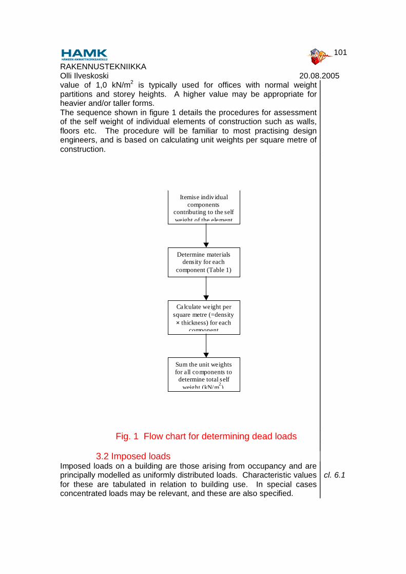
value of 1,0 kN/m2 is typically used for offices with normal weight partitions and storey heights. A higher value may be appropriate for heavier and/or taller forms.The sequence shown in figure 1 details the procedures for assessment of the self weight of individual elements of construction such as walls, floors etc. The procedure will be familiar to most practising design engineers, and is based on calculating unit weights per square metre ofconstruction.
Itemise indiv idualcomponents
contributing to the selfweight of the element
Determine materialsdensity for each
component (Table 1)
Calculate weight persquare metre (=density× thickness) for each
component
Sum the unit weightsfor all components to
determine total selfweight (kN/m2).
Fig. 1 Flow chart for determining dead loads
3.2 Imposed loadsImposed loads on a building are those arising from occupancy and are principally modelled as uniformly distributed loads. Characteristic values for these are tabulated in relation to building use. In special cases concentrated loads may be relevant, and these are also specified.
cl. 6.1

RAKENNUSTEKNIIKKA Olli Ilveskoski 20.08.2005
102
Imposed loads are generally classified as variable and free.Loads due to moveable partitions and services which may be repositioned are treated as imposed loads.The characteristic values of imposed loads are composed of long-term, medium-term, and short-term components. In practice there is often no need to distinguish between these except where materials are sensitive to time-dependent actions. For example, concrete is subject to creep, and load duration may therefore need to be considered in some aspects of the design of composite structures. Building occupancy is defined in five categories (A-E) with some sub-divisions as shown in Table 2 and corresponding characteristic imposed floor loadings are specified. These are identified in Table 3. In general, roofs with access should be designed for the same level of imposed load as for floors, but garage and vehicle traffic areas are treated separately
Table 6.1Table 6.2cl. 6.3.2
Table 2 Building occupancy categoriesTable 6.1
A Residential (including hospital wards, hotel bedrooms etc)B Office areasC Assembly areas (subdivided into 5 sections depending on
likely density of occupation and crowding)D ShoppingE Storage areas
Table 3 Characteristic imposed floor loadings Table 6.2
Loaded areas qk[kN/m2]
Qk [kN]
Category A - general 2,0 2,0- stairs 3,0 2,0- balconies 4,0 2,0
Category B 3,0 2,0
Category C - C1 3,0 4,0- C2 4,0 4,0- C3 5,0 4,0- C4 5,0 7,0- C5 5,0 4,0
Category D - D1 5,0 4,0- D2 5,0 7,0

RAKENNUSTEKNIIKKA Olli Ilveskoski 20.08.2005
103
Category E 6,0 7,0
Provision is made for reducing imposed loads on structural elements which are supporting large floor areas. The reductions are applied through a factor, α, applied according to simple formulae related to the area supported by a beam, or the number of storeys supported by a column.For beams: αA = 5ψo/7 + 10/Awhere A is the loaded area supported by the beam (m2)For columns: αn = {2 + (n –2)ψ0 }/ nwhere n is the number of storeys supportedIn both cases ψ0 is determined from EN1-1 and described in section 6.2 below.
cl. 6.3.1.2(3)
Figure 2 shows a flow chart for determining imposed load intensitiesDefine the category of
building and specific useaccording to Table 2.
From Tab le 3 determine the appropriatevalue of imposed load intensity qk
(kN/m2). Note that the alternativeconcentrated load (Qk) is intended only
for use in assessing structuralperformance over a very s mall area.
Determine imposedload reduction factors
as appropriate.
Determine the area supportedby individual beams or the
number of storeys supportedby individual columns.
In calculat ing the characteristicimposed load on individualelements, multip ly by the
corresponding reduction factor ifit is less than 1,0.

RAKENNUSTEKNIIKKA Olli Ilveskoski 20.08.2005
104
Fig. 2 Flow chart for determining imposed load intensities
4. EC1 Part 2.3 Snow loadsEC1-2-3
EC1-2-3 provides detailed guidance on the calculation of roof loads due to snow, but excludes the following: cl. 1.1.2• sites over 1500m altitude• impact loads associated with snow falling from a higher roof.• additional wind loads due to ice accretion• sites where snow is present all year• lateral loads due to snow drifting• the effect of heavy rain falling on snowAs with other Eurocodes it is organised in Chapters as follows:Chapter 1 General
This outlines the scope, defines specific terms, and provides a notation list
Chapter 2 Classification of actions. Provides brief guidance on snow as a variable, free action,
and in some cases an accidental actionChapter 3 Design situations
Provides broad comment of a rather general natureChapter 4 Representation of actions
Provides broad comment on idealisation of snow as a uniformly distributed load
Chapter 5 Load arrangementsProvides detailed guidance for calculating snow load intensities in relation to the snow load on the ground (Chapter 6) and the shape of the roof (Chapter 7).
Chapter 6 Snow load on the groundProvides the basis for determining snow load on the ground with reference to snow maps contained in Annex A.
Chapter 7 Snow load shape coefficientsProvides detailed guidance on modifications to the uniform snow load applicable to roofs of different shapes.
Annex A (Informative)
Provides detailed guidance on characteristic snow loads on the ground for different geographical locations. Where appropriate, methods of adjusting these values for altitude are given.
4.1 Determination of snow loads
Snow loads, s, are calculated on the basis of a characteristic load, sk, corresponding to a uniform depth of snow accumulated under calm conditions on flat ground. This is modified to account for the shape of
cl. 4.2

RAKENNUSTEKNIIKKA Olli Ilveskoski 20.08.2005
105
conditions on flat ground. This is modified to account for the shape of the roof and the effect of wind on the distribution of snow. (Note the value of s may be reduced by exposure and thermal coefficients which account for more severe wind conditions, and reduced thermal insulation in the roof but these are generally taken as 1,0). The characteristic values are based on snow maps for individual member states, and relate sk directly to geographical location. A typical snow map is shown in Figure 3.
cl. 6Fig. A2
3,0kN/m2
2,5kN/m2
2,5-3,0kN/m2
2,5kN/m2
2,0kN
/m2
2,5-3
,0kN/m
2
2,0-2,5kN/m2
.

RAKENNUSTEKNIIKKA Olli Ilveskoski 20.08.2005
106
Fig. 3 Snow map for Finland Fig.A2
The influence of roof geometry is accounted for by a snow load shape coefficient, µ, related to the roof pitch Conventional pitched roofs, monopitch, multi-pitch and cylindrical roofs are treated separately.
cl. 7
A typical chart giving values of snow load shape coefficient in relation to roof slope is shown in Figure 4 and Table 4. Note that for monopitch roofs two load cases should be considered, one in which the full snow load is applied over the full extent of the roof, and a second in which half the snow load intensity is applied over the most unfavourable half of the roof. The second load case will rarely be critical.
Fig. 7.3Table 7.2
(i)
(ii)
(iii)
(iv)
m2.α1
0.5m1.α1
m1.α1
m1.α2
m2.α2
α2α1
0.5m1.α2
Fig. 4. Snow load shape coefficient in relation to slope for duopitch roofs.
Fig. 7.3
Table 4 Snow load shape coefficient in relation to slope for duopitch roofs.
Table 7.2
Angle of pitch ofroof,
0° ≤ α ≤ 15° 15° ≤ α ≤ 30° 30° ≤ α ≤ 60° α ≥ 60°
Shape coefficientµ1
0,8 0,8 0,8(60 - α)/30 0,0
Shape coefficientµ2
0,8 0,8 + 0,6(α-15)/30 1,1(60-α)/30 0,0

RAKENNUSTEKNIIKKA Olli Ilveskoski 20.08.2005
107
Roofs with abrupt changes in height must account for the possibility of snow sliding from an upper level, and this is done by a further shape coefficient
cl. 7.4
Rules are given to enable the effect of snow overhanging the edge of a roof to be accounted for. These apply to those parts of a roof cantilevered out beyond the walls, but the magnitude of the allowance is independent of the length of overhang.
cl. 5.2
A flow chart for determining snow loads on roofs is shown in figure 5Determine the characteristicvalue of snow on the ground
according to geographic location,including appropriate allowance
for altitude {Annex A}.
Determine snow loadshape coefficient, µi,according to the typeof roof and its pitch
Calculate thecharacteristic snow
load on the roof:s = sk µi
Figure 5 Flow chart for determining snow loads on roofs
5. EC1 Part 2.4 Wind loadsEC1-2-4
EC1-2-4 provides detailed guidance on the calculation of wind loads As with other Eurocodes it is organised in Chapters as follows:Chapter 1 General
This outlines the scope, defines specific terms, and provides a notation list
Chapter 2 Classification of actionsDefines wind as a variable, free action.
Chapter 3 Design situationsProvides broad comment of a rather general nature
Chapter 4 Representation of actionsProvides broad comment on idealisation of wind as a uniform pressure acting normal to the surface of a building

RAKENNUSTEKNIIKKA Olli Ilveskoski 20.08.2005
108
uniform pressure acting normal to the surface of a buildingChapter 5 Wind pressure on the surface
Provides detailed guidance for calculating wind pressures on building surfaces.
Chapter 6 Wind forcesRelates wind pressures to global forces
Chapter 7 Reference windProvides detailed guidance on calculation of basic wind pressure by reference to Annex A.
Chapter 8 Wind parametersProvides detailed guidance on modifications to reference wind for special conditions
Chapter 9 Choice of proceduresDefines the conditions for using the simple procedure
Chapter 10
Aerodynamic coefficients
Provides more detailed procedures for calculating wind pressures on special structures.
Annex A (Informative)
Provides detailed guidance on reference wind speeds for different geographical locations.
Annex B (Informative)
Provides detailed procedures for assessing the dynamic behaviour of structures
Annex C (Informative)
Provides detailed rules for vortex excitation and other aeroelastic effects
5.1 Determination of wind loads
Two approaches are presented in ENV 1991-2-4. The simple method is applicable where structures are unlikely to be susceptible to dynamic excitation. In practice, steel framed buildings less than 200m tall should satisfy this condition, but for very slender or unusual structures, more detailed calculations may be required to justify this. This section covers only the simplified approach and applies to ‘permanent’ structures. In general temporary structures may be designed for lower wind pressures.
cl. 9.1
Wind loads are treated as quasi-static pressures acting normal to the surface of the building (except in special circumstances such as tangential friction forces due to wind blowing over large flat surfaces). The characteristic wind pressure is the reference mean wind velocity pressure, qref, derived from the corresponding velocity (vref,0). The reference wind velocity (vref,0) is determined from wind maps for each member state. These are detailed in Annex A of the code.. Exceptionally, the value of vref,0 may need to be modified to account for altitude or wind direction for some countries.
cl. 7.1
Annex A

RAKENNUSTEKNIIKKA Olli Ilveskoski 20.08.2005
109
Indicative values of the reference wind velocity for all of Europe are shown in Figure 6.
2220
20
22 23
30
23
32
2327
2420
26
24
28
28
30
24
26
253028
312526
28 288
293030
3028
2831
27
28 28
30
3036
27
26
28
2427
272829
30212223
262524
23
Special regulation
Fig. 6. European wind map (indicative values only). Fig. 7.2The reference wind pressure is then determined directly: cl. 7.1

RAKENNUSTEKNIIKKA Olli Ilveskoski 20.08.2005
110
qref = 0,5 ρ vref2
where ρ is the density of air, taken as 1,25kg/m3 unless otherwise specified.This is modified by an exposure coefficient ce(z), which takes account of terrain roughness according to Table 5, topography and height above ground. For ‘flat’ terrain the exposure coefficient ce(z) can be determined from Figure 7 which relates height and terrain category. Terrain is generally considered ‘flat’ except for locations close to isolated hills and escarpments.
cl.8.5 Table 8.1 Fig. 8.3
Table 5. Terrain categories and related parameters Table 8.1
Terrain Category kr zo[m]
zmin[m]
ε
I Rough open sea, lakes with at least 5km fetch upwind and smooth flat country without obstacles
0,17 0,01 2 [0,13]
11 Farmland with boundary hedges, occasional small farm structures, houses or trees
0,19 0.05 4 [0,26]
111
Suburban or industrial areas and permanent forests 0,22 0,3 8 [0,37
]IV Urban areas in which at least
15% of the surface is covered with buildings and their average height exceeds 15m
0,24 1 16 [0,46]
Note: The parameters of this table are calibrated to obtain the best fit of available data. The values kr, zo and zmin are used in 8.2, the value ε is used in Annex B (Section 3).
8.2

RAKENNUSTEKNIIKKA Olli Ilveskoski 20.08.2005
111
0 1 2 3 4 50
5
10
20
50
100
200
z (m)Specialadvice
ce (z)
IV III II I
Fig. 7. Exposure coefficient ce(z) as a function of height z above ground and terrain categories I to IV
for ‘flat’ terrain. - c1=1
Figure 8.3
Note that tall buildings may be considered in sections with appropriate height ranges, and wind pressures calculated for each section according to the corresponding ‘reference height’, as shown in fig. 8. Fig. 10.2.2
(c)(b)(a)
ze = h
h < b
b < h < 2b
b: crosswind width h > 2b
ze = h - b
ze = z
ze = b
ze = h
ze = bze = h
Fig. 8. Reference height ze as a function of the breadth and actual building height. Wind pressure may be considered separately
within the separate zones.
Fig. 10.2.2
Wind pressure distributionThe net pressure on a surface is the algebraic sum of the internal and external pressures. This is indicated in fig. 9.
cl. 5.4

RAKENNUSTEKNIIKKA Olli Ilveskoski 20.08.2005
112
external pressures. This is indicated in fig. 9. Fig. 5.1
negneg
neg
neg neg
neg
negneg
pos
pos
pos
pos
(a) (b)
(c) (d)
We1 We2 We1 We2
Positiveinternalpressure
Negativeinternalpressure
.
Fig. 9 Pressure on surfaces of buildings Fig. 5.1Wind pressure coefficients cpe and cpi are applied to determine the distribution of external and internal pressures respectively.
cl. 10
Values are tabulated for • vertical walls of rectangular buildings • flat roofs • monopitch roofs • duopitch roofs • hipped roofs A typical chart is shown in Fig. 10.and Table 6.
Table 10.2.1Table 10.2.2Table 10.2.3Table 10.2.4Table 10.2.5

RAKENNUSTEKNIIKKA Olli Ilveskoski 20.08.2005
113
e=b or 2hwhichever is smaller
wind
wind
wind
PLAN
ELEVATION
case d>e
case d<e
A B CA B
A B h
B C hAd
E bD
e/5
e/5
Key for vertical walls.
Fig. 10 External pressure coefficients for vertical walls of rectangular plan buildings.
Fig 10.2.3
Table 6 External pressure coefficients for vertical walls of rectangular plan buildings.
Table 10.2.1
Zone
A B, B* C D E
d/h Cpe,1
0
Cpe,
1
Cpe,1
0
Cpe,
1
Cpe,
10
Cpe,
1
Cpe,
10
Cpe,1 Cpe,
10
Cpe,
1
≤ 1 -1,0 -1,3 -0,8 -1,0 -0,5 +0,8
+1,0 -0,3
≥ 4 -1,0 -1,3 -0,8 -1,0 -0,5 +0,6
+1,0 -0,3
For buildings without internal partitions internal pressure coefficients are related to the opening ratio, µ, which is defined as:
cl. 10.2.9Fig. 10.2.11
µ = Total area of openings at the leeward and wind parallel sides Total area of openings at the windward, leeward and wind parallel
sidesFor an homogeneous distribution of openings for an approximately square building, cpi may be taken as -0,25.For closed buildings with internal partitions, the worst case may be assumed:

RAKENNUSTEKNIIKKA Olli Ilveskoski 20.08.2005
114
assumed:cpi = 0,8, or cpi = -0,5Special consideration is given to canopy roofs, buildings with more than one skin, solid boundary walls, fences and signboards, and special structures.The process for determining wind loads on a building is summarised in fig. 11.

RAKENNUSTEKNIIKKA Olli Ilveskoski 20.08.2005
115
Mean wind velocity: vref – (wind ‘maps’)– exceptionally modified for alt itude ordirection
Mean pressure qref =0,5 ρ vref
2 (ρ = 1,25)
Reference height z
Pressure coefficientsExternal pressure: cpe – Tables 10.2.1-5 for walls and
roofs of various shapes
Internal pressure: cpi calculated in relat ion to µ, rat ioand distribution of openings
Repeat for alternative wind directions
Terrain category I-IV
Exposurecoefficient ce(ze)
External pressurewe = qref ce(ze) cpe
Internal pressure wi
= qref ce(zi) cpi
Net pressure onsurface = we +/- wi

RAKENNUSTEKNIIKKA Olli Ilveskoski 20.08.2005
116
Fig. 11. Flow chart for calculating wind pressures (for buildings not susceptible to dynamic excitation - in practice this applies to 'normal buildings less than
200m high).
cl. 9.2
6. Load cases6.1 Design values of loads
Design values are obtained from characteristic values multiplied by appropriate partial safety factors. These account for accidental overloading and inevitable inaccuracies in the analysis. They also implicitly incorporate the global factor of safety necessary in structural design. The magnitude of the partial safety factor depends on the limit state under consideration and the particular type of action. These are detailed in Table 7 which includes three 'classes' for consideration. Class A refers to loss of static equilibrium and should be used, for example, where consideration of overall stability is considered. Class B refers to failure of structure or structural elements and is the condition most likely to apply. Class C refers to cases associated with failure of the ground.The basic values of partial safety factors to be used in design for Class B - failure of structure or structural elements are summarised in Table 7 for both ultimate (Class B) and serviceability limit states..
Table 7. Basic values of partial safety factors - Class B (failure of structure or structural elements)
ULS SLS Table 9.2Q G Q G
Unfavourable effect
1,5 (1,35)*
1,35 1,0 (0,9)*
1,0
Favourable effect
0,0 1,0 - -
*Note that two values are quoted for variable loads. The appropriate value depends on whether a single variable load, or a combination of, for example, imposed and wind loads, is considered, and the simplified method for dealing with load combinations is adopted. This is discussed in more detail below. Note also that the characteristic values of all permanent actions from one source are multiplied by 1,35 if the total effect is unfavourable or by 1,0 if it is favourable. This implies, for example, that for a continuous beam the self weight of the floor should be factored by the same factor for all spans, with no allowance for pattern loading due to permanent actions. For consideration of Class A (loss of equilibrium) the following partial safety factors apply:Unfavourable

RAKENNUSTEKNIIKKA Olli Ilveskoski 20.08.2005
117
Permanent γ = 1,1Variable γ = 1,5
FavourablePermanent γ = 0,9Variable γ = 0,0
6.2 Combination valuesWhen a load combination includes more than one variable load (for example imposed loads and wind loads) the partial safety factors relating to the variable load components change, and each variable load, except the one which has the greatest effect, is multiplied by a combination factor, ψ. If it is not clear which variable load has the greatest effect, all combinations should be considered.The value of the the combination factor to use depends on the circumstances, the load type, and the use of the building. For 'normal' circumstances (other than those concerning accidental or seismic situations), the appropriate factor is designated ψ0. The values of ψ0 are as follows:Imposed loads for all buildings except storage:
0,7
Imposed loads for storage buildings
1,0
Snow loads 0,6Wind loads 0,6Potentially this gives rise to a very large number of possible load combinations, each of which would require separate consideration and analysis. Fortunately, a simplified approach is allowed for conditions known from previous experience to be critical, and this should be satisfactory for most building designs.. The simplified approach is described below.
6.3 Simplified treatmentsEC1 includes a simplified treatment for building structures in normaldesign situations. This eliminates the use of the combination (ψ) factors and uses modified partial load factors. These expressions imply a single permanent action, generally comprising the dead load, Gk. The dead load will be combined with appropriate variable actions, typically those due to imposed, snow and wind loads. For simple floor and roof structures the predominant actions are gravity loads (dead and imposed for floors; dead and snow for roofs), but for framed structures the additional influence of wind loads must of course be considered in combination. Thus typical load combinations for cases where the actions are all detrimental are as follows:Serviceability Limit State (for Class B - failure of structure or structural elements):Dead + imposed (or snow): Gk + QkDead + imposed (or snow) + wind: Gk + 0,9 Σ Qk

RAKENNUSTEKNIIKKA Olli Ilveskoski 20.08.2005
118
Ultimate Limit State (for Class B - failure of structure or structural elements)Dead + imposed (or snow): 1,35 Gk + 1,5 QkDead + imposed (or snow) + wind: 1,35 Gk + 1,35 Σ QkIn some circumstances, certain actions may have a beneficial effect. For example dead loads may assist in resisting wind or overturning, and imposed loads on the central span of a continuous beam can relieve bending in the adjacent spans. Under these circumstances the lower value (inferior) of the partial safety factor should be applied to the beneficial action. In practice, for Class B conditions, imposed loads which are beneficial are simply ignored (γinf = 0), whilst for dead loads resisting wind effects, a partial factor of 1,0 should be used.
7. Worked Examples
7.1 Dead loadsThe floor construction of a commercial office building consists of:50mm sand/cement screed150mm normal weight reinforced concrete slab12mm plaster (gypsum mortar) ceilingDensities for each of these materials can be found from EC1-2-1 Table 4.1. These can be used to determine the dead load intensity (kN/m2) as indicated in Table below.
Component
Density(kN/m3)
Thickness (m)
Load intensity=density × thickness
(kN/m2)Screed 20 (19 - 23) 0,05 20 × 0,05 = 1,0Slab 24 0,15 24 × 0,15 = 3,6Plaster 15 (12 - 18) 0,012 15 × 0,012 = 0,2
Including allowances for partitions and services the calculations may be set out as follows:Screed 20 × 0,05 = 1,0 kN/m2
Slab 24 × 0,15 = 3,6Plaster 15 × 0,012 = 0,2Partitions = 1,0Services = 0,3Total charachteristic load = 6,1 kN/m2
7.2 Imposed loadsConsider the case of a commercial office building. From EC1-2-1 Table 6.1, the occupancy relates to category B (offices) and from Table 6.2 the corresponding imposed floor load intensity is 3,0 kN/m2.For beams and columns attracting load from wide areas, this value can be reduced.

RAKENNUSTEKNIIKKA Olli Ilveskoski 20.08.2005
119
Consider a main floor beam spanning 10m and supporting secondary beams which span 8m. The total area, A, supported by the main beam is therefore:A = 10,0 × 8,0 = 80 m2
The corresponding reduction factor α is then given by:αA = 5ψo/7 + 10/AFor imposed floor loads (excluding storage areas) ψo = 0,7 αA = 5 × 0,7 /7 + 10 / 80 = 0,5 + 0,125 = 0,625The imposed load to the beam can be reduced by this factor.If the beam is subject to the dead load intensity specified in 7.1 above the total beam load is as follows:Dead load 6,1 × 8,0 × 10,0 = 488 kNImposed load 0,625 × 3,0 × 8,0 ×
10,0= 150 kN
For typical ultimate limit state calculations these would be combined using appropriate partial safety factors (1,35 for dead loads and 1,5 for imposed loads)Design load to beam (ULS) = 1,35 × 488 + 1,5 × 150 = 659 + 225 = 884 kNFor typical serviceability limit state calculations these would be combined using appropriate partial safety factors (1,0 for dead loads and 1,0 for imposed loads)Design load to beam (SLS) = 488 + 150 = 638 kNFor columns: αn = {2 + (n –2)ψ0 }/ nwhere n is the number of storeys supportedThus for a column supporing 4 storeys:αn = {2 + (4 –2) × 0,7}/ 4 = 0,85If the column supports two of the beams detailed in the previous example at each storey, the total dead and imposed column loads are as follows:Dead load = 4 × 488 = 1952 kNImposed load = 4 × 0,85 × 3,0 × 8,0
× 10,0= 816 kN
For typical ultimate limit state calculations these would be combined using appropriate partial safety factors (1,35 for dead loads and 1,5 for imposed loads)Design load to column (ULS) = 1,35 × 1952 + 1,5 × 816 = 2635 + 1224 = 3859 kN

RAKENNUSTEKNIIKKA Olli Ilveskoski 20.08.2005
120
7.3 Snow loadsEC1-2-3
W1 W2
A building in Helsinki has a 24° duo pitched roof. The characteristic snow load on the ground sk, is 2,5 kN/m2 Figure A2The snow load shape coefficients for the roof are:µ1 = 0,8; µ2 = 0,8 + 0,6 (24 - 15) / 30
= 0,8 + 5,4 / 30= 0,8 + 0,18 = 0,98
Figure 7.3Table 7.2
Possible load arrangements:W1 = 0,98 ×2,5
= 2,45 W2 = 0,8 ×2,5
= 2,0
W1 = 0,5 × 0,8 × 2,5
= 1,0 W2 = 0
Consider the same roof as above but with unequal slopes of 24° and 36°.µ13
6
= 0,8 (60 - 36) / 30 = 0,64
µ124 = 0,8
µ23
6
= 1,1 (60 - 36) / 30 = 0,88
µ224 = 0,98
Possible load arrangements:W1 = 0,88 × 2,5
= 2,2 W2 = 0,8 × 2,5
= 2,0W1 = 0,5 × 0,64 × 2,5
= 0,8W2 = 0
W1 = 0,64 × 2,5 = 1,6
W2 = 0,98 × 2,5 = 2,45
W1 = 0 W2 = 0,5 × 0,8 × 2,5 =1,0
Notes:Even for a flat roof there is a reduction factor of 0,8.In most cases it may be conservatively assumed that maximum snow load intensity is applied uniformly across the full width of the roof.

RAKENNUSTEKNIIKKA Olli Ilveskoski 20.08.2005
121
7.4 Wind loadsConsider a building in suburban Athens, 30m high and with plan dimensions 20m × 20m. The building is 'closed' with internal partitions.Mean wind velocity vref = 36 m/sMean wind pressure qref = 0,5 × 1,25 × 362 = 0,81 kN/m2
Reference height: consider the building in two zones ze = 20m and ze = 30m.Terrain category III (kt = 0,22; ze(m) =0,3; zmin(m) = 8; e = 0,37)Exposure coefficientsce(20) = 2,25; ce(30) = 2,55Pressure coefficients:Internal pressure coefficient cpi = 0,8 or -0,5External pressure coefficients:d/h = 20 / 30 = 0,67e = smaller of b (= 20) and 2h (= 60), so e = 20 d = e so consider wind pressure on side walls of building as uniform (ie pressures in zones B, B* and C are all equal) - except for leading corner (zone A).
A B/B* D ECpe10 -1,0 -0,6 +0,8 -0,3Cpe1 -1,0 -1,0 +1,0 -0,3
External wind pressure:Up to 20m:A: we(2
0)
= 0,81 × 2,25 × (-1,0)
= -1,82 kN/m2
B::
we(2
0)
= 0,81 × 2,25 × (-0,8)
= -1,46 kN/m2
D we(2
0)
= 0,81 × 2,25 ×(+0,8)
= +1,46 kN/m2
E: we(2
0)
= 0,81 × 2,25 × (-0,3)
= -0,55 kN/m2
From 20m to 30mA: we(3
0)
= 0,81 × 2,55 × (-1,0)
= -2,07 kN/m2
B: we(3
0)
= 0,81 × 2,55 × (-0,8)
= -1,65 kN/m2
D: we(3
0)
= 0,81 × 2,55 ×(+0,8)
= +1,65 kN/m2
E: we(3
0)
= 0,81 × 2,55 × (-0,3)
= -0,62 kN/m2
Internal wind pressureUp to 20m:Positive (pressure):
wi(20) = 0,81 × 2,25 ×(+0,8)
= +1,46 kN/m2

RAKENNUSTEKNIIKKA Olli Ilveskoski 20.08.2005
122
(pressure): (+0,8)Negative(suction):
wi(20) = 0,81 × 2,25 × (-0,3)
= -0,55 kN/m2
From 20m to 30mPositive (pressure):
wi(30) = 0,81 × 2,55 ×(+0,8)
= +1,65 kN/m2
Negative (suction):
wi(30) = 0,81 × 2,55 × (-0,3)
= -0,62 kN/m2
Net wind loads are calculated by combining the internal and external wind pressures algebraically. In doing so it is important to be consistent in relation to wind direction, and direction of internal pressureNote that for rectangular (not square) buildings it will be necessary to consider wind in two orthogonal directions.
7.5 Load combinations7.5.1 3-span continuous beam (ULS for failure of structure)
W1 W2 W3
For consideration of failure of structural elements partial safety fators are determined from Table 9.2. For a three span continuous beam, a number of conditions must be considered. These correspond to different combinations of loading on the three spans. If these are designated W1, W2 and W3 and the beams each span 10m, are at 8m centres, and are subject to loadings as calculated in 7.1-2 above) the load combinations to be considered are as follows:Maximum bending in span 1:W1 = 1,35 Gk + 1,5 Qk; W2 = 1,35 Gk; W3 = 1,35 Gk + 1,5 QkW1 = W3 = 884 kNW2 = 1,35 × 488 = 659 kNMaximum bending in span 2:W1 = 1,35 Gk; W2 = 1,35 Gk+ 1,5 Qk; W3 = 1,35 GkW1 = W3 = 659 kN W2 = 884 kNFor maximum loads in the supporting internal columns, the maximum load would be considered for all spans, ie W1 = W2 = W3 = 884 kN

RAKENNUSTEKNIIKKA Olli Ilveskoski 20.08.2005
123
7.5.2 2-storey building - single bay with balcony (ULS - loss of equilibrium)
Wf1
Wr1
Wf2
Wr2
Wh
Wh
For consideration of loss of equilibrium partial safety factors are determined from Table 9.1.For a 2-storey single bay building with cantilever, a number of conditions must be considered. These correspond to different combinations of dead, imposed and wind loading, including different patterns of vertical load on the span and cantilever at first floor and roof. If the loads are designated Wr1, Wr2 (for the roof span and cantilever), Wf1, Wf2 (for the floor span and cantilever), and Wh is the horizontal load due to wind, the load combinations to be considered are as follows:ψ0 = 0,6 (snow load); ψ0 = 0,6 (wind loads); ψ0 = 0,7 (floor imposed loads)Wr2 = 1,35 Gkr + 1,35 QkrWf1 = 1,0 GkfWf2 = 1,35 Gkf Considering imposed roof loads dominant:Wr1 = 1,0 GkrWr2 = 1,35 Gkr + 1,5 QkrWf1 = 1,0 Gkf
Wf2 = 1,35 Gkf + ψ0 (floor) (1,50 Qkf)= 1,35 Gkf + 0,7 × 1,50 Qkf= 1,35 Gkf + 1,05 Qkf
Wh = ψ0 (wind) (1,5 Wk)= 0,6 × 1,5 Wk
= 0,9 Wk

RAKENNUSTEKNIIKKA Olli Ilveskoski 20.08.2005
124
Considering imposed floor loads dominant:Wr1 = 1,0 Gkr
Wr2 = 1,35 Gkr + ψ0 (snow) (1,50 Qkr)= 1,35 Gkf + 0,6 × 1,50 Qkr= 1,35 Gkf + 0,9 Qkr
Wf1 = 1,0 GkfWf2 = 1,35 Gkf + 1,5 Qkf
Wh = ψ0 (wind) (1,5 Wk)= 0,6 × 1,5 Wk
= 0,9 Wk
Considering wind loads dominantWr1 = 1,0 Gkr
Wr2 = 1,35 Gkr + ψ0 (snow) (1,50 Qkr)= 1,35 Gkf + 0,6 × 1,50 Qkr= 1,35 Gkf + 0,9 Qkr
Wf1 = 1,0 Gkf
Wf2 = 1,35 Gkf + ψ0 (floor) (1,50 Qkf)= 1,35 Gkf + 0,7 × 1,50 Qkf= 1,35 Gkf + 1,05 Qkf
Wh = 1, 5 Wk
Considering all variable loads in combination using the simplified approach:Wr1 = 1,0 GkrWr2 = 1,35 Gkr + 1,35 QkrWf1 = 1,0 GkfWf2 = 1,35 Gkf + 1,35 QkfWh = 1,35 Gk
8. Concluding Summary• The principal actions to be considered in the design of buildings are dead and imposed loads, snow, and wind. . • Dead loads are calculated on the basis of material densities specified in EC1-2-1 and construction details• Imposed loads are defined in EC1-2-1 in relation to building usage, classified as residential, office, assembly (subdivided according to likely density of occupation), shopping , and storage. • Calculation procedures for snow loads are detailed in EC1-2-2 and are based on geographical location and roof shape.• Calculation procedures for wind loads are detailed in EC1-2-3 and are based on • For most buildings wind loads can be assumed to be determined from quasi-static pressures determined according to location, exposure and building height.

RAKENNUSTEKNIIKKA Olli Ilveskoski 20.08.2005
125
• Internal wind pressures depend on the distribution of openings in walls.• The distribution of external wind pressures on walls and roof slopes depends on the geometry of the building• Partial safety factors are used to account for uncertainties in load levels; values depend on load type, the limit state considered, and the design condition (structural failure, loss of equilibrium or failure of the ground) • Partial safety factors are modified to account for different combinations of actions, but a simplified approach can be adopted.