Today's Aerospace vehicles utilise numerous pyrotechnic devices to separate structural

Advanced Steel Construction Vol. 3, No. 1, pp. 431-442 (2007) 431
STRUCTURAL STEEL DESIGN CODES: VEHICLES FOR IMPROVING PRACTICE OR
FOR IMPLEMENTING RESEARCH?
D.A. Nethercot
Department of Civil and Environmental Engineering, Imperial College London, UK (Corresponding author: E-mail: [email protected])
Received: 11 May 2006; Revised: 19 August 2006; Accepted: 22 August 2006
ABSTRACT: Drawing on over 30 years of personal involvement with the preparation of codes of practice for structural steel design, the issue of academic elegance versus practitioner practicality is discussed. Several examples taken from recently produced codes are used to illustrate different manifestations of the issue. The matter is discussed within the wider context of both the growing internationalisation of codes and the substantial supporting infrastructure needed by designers to efficiently implement their provisions. Although the specifics relate largely to the design of steel buildings in the UK and the wider European context, it is thought that the points stated, lessons learned and recommendations made are of general relevance.
Keywords: codes of practice, design, steel structures, structural engineering
1. INTRODUCTION Design Codes covering some aspects of steel construction started to become a feature in several countries during the early and middle part of the last century (Baker [1]). Initially, these tended not to be national documents but rules and procedures with varying degrees of comprehensiveness and differing scientific bases issued by City authorities and other organisations with some sort of responsibility for the control of construction. Not surprisingly, there was great variation, leading to various levels of safety within the same country and giving considerable difficulty to those organisations wanting to work across several different districts. Within the UK, so-called sets of rules for steel construction often concentrated on fire prevention in buildings, gave some information on loading and provided general guidance on the principles of overall stability of construction. Detailed rules for the proportioning of individual elements based on an appreciation of the mechanics of load resistance were not necessarily the main feature. These local documents were quickly followed by the first generation of National Codes. However, there was still significant variation between rules covering similar issues provided by different countries, since the concept of a generally accepted underlying research base had yet to become established. It was also the case that a “Code of Practice” was often essentially just that i.e. the encapsulation of established good practice rather than the setting down of a collection of scientifically based procedures. Increasing steel production, plus the need in several regions around the world to rebuild, meant greatly increased development in the period immediately following the end of the 2nd World War. For example, the construction of many steel bridges in Germany led to the emergence of DIN 4114, covering advanced aspects of buckling and steel plated structures that, because of the absence of any form of local equivalent, was used for many major bridge projects extending far beyond Germany. Other forms of influence e.g. the former British Commonwealth and American presence overseas, meant that documents originally produced for home use often found significant take-up elsewhere – sometimes explicitly and sometimes implicitly in the form of simply being copied and issued as the local Code. Of course, objections tended to be muted since “imitation is

432 D.A. Nethercot
the sincerest form of flattery”. During the 50s, 60s and 70s activity surrounding the preparation of Codes developed rapidly (2). New editions giving improved coverage of an ever wider range of topics were produced, completely new areas such as: composite construction, light gauge steelwork and stressed skin design, were addressed. Newer formats e.g. limit states design, were adopted. Much of this was driven by the regulatory side for whom the phrase “Is it in accordance with the Code” gave an all too easy method of discharging their responsibilities for construction safety. Much was underpinned by the growing body of research data that meant that it now became possible to provide rules and procedures for topics previously considered “too difficult”. Not all this development was necessarily Government driven. In several areas Industry played a significant role e.g. AISC in the United States is not the National Bureau of Standards. Moreover, in some cases where no Code was provided, industry (or industry representative bodies) took the lead to develop guidance. In the UK the phrase “plastic design to BS 449” was often used; the Code (3) contained just two general sentences; “You may use it. The load factor shall be 1.7”. All detailed rules were given in a pair of BCSA Black Books (Burnett [4] and Horne [5]). Growing internationalisation of the construction industry, plus greater interactions within the research community have, in the last third of the 20th Century, led to a growing body of activity designed to prepare Codes valid across national boundaries. The prime example of this is, of course, within the EU, leading to the preparation and issue of the Structural Eurocodes – specifically EC3 for Steelwork and EC4 for Composite Construction - as part of the suite of 10 documents covering Structural Design in all the main materials. But other, far reaching, collaborations also exist e.g. the decision of Australia and New Zealand (themselves two hours flying time apart) to work with the United States and Canada on a joint Code covering light gauge steel construction. Based very much on the author’s personal experience during the past 35 years, this paper explores some of the issues faced by modern steel design codes. These include: simplicity versus rigour, brevity versus comprehensiveness, safety and economy, elegance versus ease of use, transparent rules versus computational procedures etc. It also exposes the tensions sometimes observed between the research community’s desire for technical advance and the practitioner’s wish for greater economy. 2. ROLE OF CODES In the UK BS0 – a Standard for Standards – lists the six aims of Standardisation as:
(i) To simplify the growing variety of products and procedures. (ii) To improve communication. (iii) To promote overall economy. (iv) To ensure safety. (v) To protect consumer and community interests. (vi) To eliminate trade barriers.
The possibilities for conflict are immediately clear. Will (i) and (iii) always agree? Can (iii), (iv) and (v) always be reconciled? More particularly, in presenting the background thinking to the development of the Part 3 of
Structural Steel Design Codes Vehicles for Improving Practice or for Implementing Research? 433
BS5400 to a conference in 1980 (Flint [6]) the Chair of the Committee responsible, Dr A R Flint, identified 5 parties, each with different legitimate requirements from that Steel Bridge Code. Leaving aside the owners, fabricators and suppliers of steel, it is of interest to contrast his concept of the requirements of designers and researchers:
• “Designers have different priorities. Many plead for simplicity in a Code both for speed of application and to enable it to be used by engineers with limited experience. Some expect rules to be both simple and all embracing. Others accept that they should refer to fundamental knowledge when designing major bridges and want freedom for experienced designers to work beyond the scope of a Code. Those competing for world-wide markets require the Code to produce the “most economical” bridges. Simplicity of design rules and economy in the material content of a bridge are incompatible for other than the simplest structures.”
• “Researchers desire a Code to be technically perfect and comprehensive, making use of the
most recent research results.” Without the direct involvement of those responsible for the latest technical developments in the subject area i.e. the researchers, in the Code drafting process, how is it possible to ensure that the most up to date thinking has been properly embodied? But if the representatives of the research community merely see the preparation of a new Code as an opportunity to promote their latest ideas – even to the extent of proposing incomplete and untried approaches based on work that is yet to receive public scrutiny – then their contribution amounts to an exercise in vanity rather than the guarantee of intellectual rigour. The solution is, of course, that the researchers need to act in a statesmanlike fashion, making objective decisions and offering sound advice that accords with the best interests of the task in hand rather than be influenced by personal preferences. 3 POTENTIAL TENSIONS 3.1 Ease of Use versus Academic Nicety
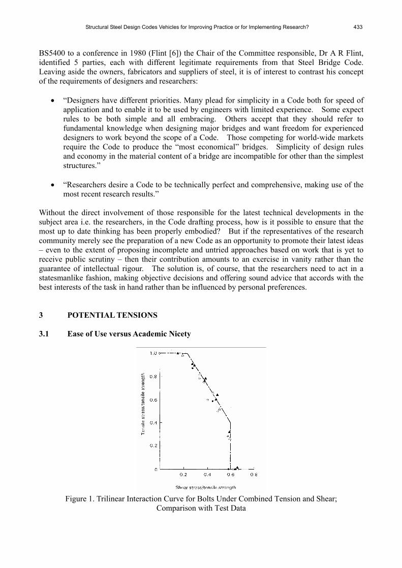
Figure 1. Trilinear Interaction Curve for Bolts Under Combined Tension and Shear;
Comparison with Test Data

434 D.A. Nethercot
Figure 1 presents a typical set of test data (Kulak [7]) for the strength of bolts subjected to combined tension and shear, a condition often found in practical connections. Several forms of interaction relationship are possible. Two particular arrangements are:
1 Some form of curved interaction e.g. reference (Kulak [7]) suggests:
0.1y )62.0(
22
3
=+x
in which x = ratio of shear stress on the shear plane to the tensile strength y = ratio of tensile stress to the tensile strength
2 Trilinear The former is obviously elegant and allows a single formula to cover all combinations. The later appears less straightforward when given as a formula yet has two great practical advantages. In many cases the full tensile (or shear) resistance may be used. Design calculations are much simpler, since providing the applied tension (or shear) is less than the 60% of the full capacity corresponding to the plateau limits in the figure, the actual value is immaterial in terms of its effects on the other resistance quantity. Since it is rare in practice to find that the same bolts are required to resist high levels of both tension and shear, the great majority of design arrangements will not fall on the inclined part of the diagram and the actual design check will therefore be much simpler. Thus designers arc likely to prefer the convenience of the trilinear rule, whereas researchers might well advocate the elegance of the circular arc representation. Clearly a potential for conflicting views! 3.2 Guidance on Implementation versus Limitation to Principles A fundamental parameter used when checking the bending resistance of laterally unrestrained beams is the elastic critical moment Mcr. This property may either appear explicitly in the design formula or be used implicitly in some form of equivalent slenderness. Calculation of Mcr is lengthy and involves properties not familiar to most users e.g. warping rigidity of the cross-section. Thus some codes assist the designer by providing specific guidance on the determination of Mcr. For example, in BS 5950: Part 1 Mcr is not used explicitly but forms part of the “lateral-torsional slenderness” λLT, for which a full calculation procedure is provided. In contrast EC3 not only uses Mcr directly but provides no assistance in its calculation. Designers must therefore make reference elsewhere. For cross-sections other than doubly symmetrical I-sections e.g. unequal flange I-beams, working from first principles is particularly tedious. Thus the EC3 procedure first requires the calculation of Mcr; no specific guidance is provided so the user must resort to textbooks (Trahair [8]) or design guides (9). For bisymmetrical I-section the elastic critical moment Mcr may be obtained from:

Structural Steel Design Codes Vehicles for Improving Practice or for Implementing Research? 435
( ) ( )
½
2
2
2
2
⎪⎭
⎪⎬⎫
⎪⎩
⎪⎨⎧
⎥⎦
⎤⎢⎣
⎡+
⎥⎥⎦
⎤
⎢⎢⎣
⎡=
kLEI
JGkL
EImM wy
crππ
in which m = factor that depends on the shape of the in-plane bending moment distribution
EIy = minor axis flexural rigidity GJ = torsional rigidity EIw = warping rigidity k = effective length factor allowing for end restrain in the buckling plane L = length between points of effective lateral restraint If the cross-section has unequal flanges but is still symmetric about its minor axis i.e. a monosymmetric beam, then the expression for Mcr contains additional properties:
⎪⎭
⎪⎬
⎫
⎪⎩
⎪⎨
⎧
⎟⎟⎠
⎞⎜⎜⎝
⎛+
⎥⎥⎥
⎦
⎤
⎢⎢⎢
⎣
⎡
⎪⎭
⎪⎬⎫
⎪⎩
⎪⎨⎧
⎟⎟⎠
⎞⎜⎜⎝
⎛++
⎪⎭
⎪⎬⎫
⎪⎩
⎪⎨⎧
=½
2
2½2½
2
2
2
2½
2
2
22 LEI
LEI
LEI
JGLEI
mM yywycr
πβπβππ
in which β is monosymmetric parameter (8) Once a value for Mcr has been determined the buckling resistance moment Mb is calculated from:
( ) ⎥⎥⎦
⎤
⎢⎢⎣
⎡
−+= ½22
1
LTLTLT
yyb fWMλβφφ
in which Wyfy = cross-sectional moment of resistance (Wy depends on section classification) LTφ = ( ){ }2
015.0 LTLTLTLT λβλλα +−+
and LTλ = [ ]½/ cryy MfW is the modified slenderness
βα ,LT and 0LTλ are defined in the Code; LTα and 0LTλ control the positioning of the design curve.
Clearly the above represents an extremely lengthy calculation process, especially if trial and error is necessary, with no guidance being provided on how best to arrange the calculation, what shortcuts might be acceptable if some degree of conservation/inaccuracy could be accepted etc. Contrast this with the designer-oriented approach of BS 5950: Part 1 to determine Mb. Mb = Pb Zex in which pb = buckling strength, pb = f(py, LTλ )

436 D.A. Nethercot
Zex = approximate section modules Determination of pb is facilitated through the introduction of LTλ defined by:
LTλ = ( ) ( ){ }½½2 // crcxy MMpEπ in which py = material design strength Mcx = in-plane moment capacity, py Zex Mcr = elastic critical moment Rather than use Mcr explicitly, however, LTλ may be calculated from:
wLT uv βλλ = in which v is tabulated for standard sections or may safely be taken as 0.9 for standard hot rolled sections or 1.0 otherwise:
( )[ ] ¼½/05.01 −+= xv λ
yrL /=λ x is also tabulated for standard rolled sections or may be approximated by D/T
xexw SZ /=β Since for compact sections Zex = Sx and noting that v is normally not much less than unity, the particularly simple approximation: 0.10.19.0 xxxLT λλ = may be used to obtain a safe (high) estimate and thus a safe (low) value for pb and hence Mb. No similar quick simplification of the EC3 approach appears possible. 3.3 Level of Detail One of the fundamental pieces of information required when designing a composite beam is the strength of the shear studs used to transfer the interface forces between the steel and concrete surfaces. Its basis is normally some form of representation of test data – obtained from a combination of laboratory push-off and/or beam tests for representative samples. Over the years a general consensus has emerged that a pair of design equations, covering the two basic failure modes of stud shear and concrete crushing, is appropriate (8). PRd = ( )4/08.0 2dfu π stud shear
PRd = ( )½2029.0 cmck Efd concrete crushing in which fu = ultimate tensile strength of the steel d = shank diameter

Structural Steel Design Codes Vehicles for Improving Practice or for Implementing Research? 437
fck = cylinder strength of concrete Ecm = mean secant modulus of concrete Forms of composite beam beyond basic flat slab arrangements have become increasingly common in recent years. One particular manifestation is the use of metal decking as an aid to the construction process. Manufacturers around the world have been in competition to produce ever more efficient (in terms of structural performance) and effective (in terms of usage of concrete and the inclusion of practically useful factors) profiles. In order to allow for the presence of metal decking, design rules for shear connections in flat slabs have traditionally included empirical coefficients, obtained from tests on each profile. Table 1 reproduces the EC4 material. Strictly speaking, as each new deck is introduced more tests and a further set of coefficients are required. Not only has this not always happened but the appearance of ever more complex profiles has seen the identification of new forms of failure not possible with plain concrete. (9) These cannot, of course, be properly handled by further extrapolation of the original design concept i.e. the pair of equations governing only stud shear and concrete crushing.
Table 1. EC4 Modification Factors for Dealing with Metal Decking Case Reduction factor
Ribs parallel to beam k1 = 0.6
p
o
hb
⎟⎟⎠
⎞⎜⎜⎝
⎛−1
phh 0.1≤
Ribs perpendicular to beam kt =
p
o
r hb
N7.0 ⎟
⎟⎠
⎞⎜⎜⎝
⎛−1
phh 0.1≤
in which Nr = number of studs in one rib where it crosses the beam < 2 h = > hp + 75 mm and the other terms are defined in the diagrams below
The situation is now such that even if code modifications could keep pace with the introduction of each new deck profile, the catalogue of coefficients – each directly related to a particular commercial product – would be both too lengthy for a Code and would contravene a firmly established principle that Codes should not relate directly to particular commercial products, remaining at the level of generic guidance. One solution would be to remove all but the basic generic guidance and to rely on manufacturers themselves to provide the specialist information required for their own products. It would therefore be in their interests to ensure that this was kept up to date. A precedent already exists in the area of light gauge steel design, where much design information is provided by the manufacturers of purlins, sheeting systems etc. Not only does this remove any linkage in the

438 D.A. Nethercot
Code to particular products, it also encourages manufacturers to conduct their own scientific studies and thus to understand the performance of the items they manufacture and sell since it is normally possible to produce more competitive procedures on the basis of specialist testing than by relying simply on the straightforward application of the generic code procedures. 3.4 Formulation The most general component in a steel frame is the beam-column, a member subjected to combined compression (or tension) and bending about both principal axes. Design rules normally rely on the use of some form of interaction equation linking resistances under each basic type of loading when acting alone. Figure 2 gives both a pictorial representation of a uniaxial bending interaction diagram and the 3-dimensional interaction surface necessary for the biaxial case (Menzies [10]). The precise shape of the interaction for any particular arrangement will, of course, depend on the details e.g. shape of cross-section, exact load arrangements, form of support etc.
Figure 2. Uniaxial Interaction in Terms of Elastic Limit and Effect of Moment Gradient β
Figure 2. Indicative Interaction Surface for Slender Beam Columns Under Biaxial Loading
The emergence of numerical analysis as a credible alternative to laboratory testing as a means of determining the true ultimate strength of structural components has been a feature of structural steel

Structural Steel Design Codes Vehicles for Improving Practice or for Implementing Research? 439
research over the past 20 years. Once the numerical models have been properly validated against representative test data, it becomes possible to conduct far more detailed parametric studies, in which the effects of systematic changes in key variables are examined, than was the case when this needed to be done in the laboratory. The result has been a far better appreciation of “cause and effect” i.e. the influence of each key parameter on behaviour or in terms of the beam- column problem an understanding of precisely how the interaction relationship is affected by different parameters. This has naturally led to a wish to see this improved knowledge reflected in more rigorous design procedures. The result in EC3 is that the design rules for beam-columns are extremely complex. Two procedures are given and both incorporate several coefficients that in turn depend on a number of properties of the system under consideration. They adopt the form:
1//,/ 1,
,
1
,
1
≤++MRkz
Edzyz
MRkyLT
Edyyy
MRky
dE
MM
kMM
kNN
γγχγχ
1//,/ 1,
,
1
,
1
≤++MRkz
Edzzz
MRkyLT
Edyzy
MRkz
dE
MM
kMM
kNN
γγχγχ
in which NEd, My,Ed, and Mz,Ed are the design values of the compression force and the
maximum moments about the y-y and z-z axis along the member, respectively
NRk, My,Rk, Mz,,Rk are the characteristic values of the compression resistance of
the cross section and the bending moment resistances of the cross-section about the y-y and z-z axes, respectively
χy and χz are the reduction factors due to flexural buckling χLT is the reduction factor due to lateral torsional buckling taken
as unity for members that are not susceptible to torsional deformation
kyy, kyz, kzy, kzz are interaction factors kij All of the terms apart from the interaction factors k are reasonably straightforward as they follow directly from, the individual load and resistance effects. However two alternative procedures for calculating the k-factors are given. Both run to 2 pages of tabulated formulae that, themselves, introduce further parameters. In addition, different expressions are required for members “not susceptible to torsional deformation” or ”susceptible to tostional deformations” as well as for class 1 and 2 sections and for class 3 and 4 sections. Both procedures have been calibrated against appropriate numerical data (Boissonnade [13] and Lindner [14]). This has resulted in procedures that give a very close representation for those cases used in their derivation. Two criticisms may be levelled at this:

440 D.A. Nethercot
• Lack of transparency i.e. it is very difficult for a designer to see the linkage between some of the problem parameters and the likely result in terms of the effect on the interaction calculation.
• Restricted applicability i.e. although the design formulae have been very precisely calibrated for certain arrangements, their use for situations that do not conform to one or other of these is, effectively, unknown.
Codes produced before the availability of such comprehensive but selective data tended to use more general design approaches e.g. the Chen concept (12) defined as:
0.1>⎟⎟⎠
⎞⎜⎜⎝
⎛+⎟
⎟⎠
⎞⎜⎜⎝
⎛ β
cz
Edz
cy
Edy
MM
MM
in which Mcy and Mcz are the resistance moments in the presence of the axial load Ned and βα , are appropriate powers, taken as 1.0 for the most conservative interpretation and provided detailed procedures for a limited number of cases for which more substantial data existed. Cases outside this range could then be dealt with by adopting the most conservative interpretation of the design concept, in the expectation that it would lead – even for cases that had not previously been examined in a more rigorous fashion – to safe results. It was also possible for designers to use the simpler and conservative form of the design expressions for preliminary checks so as to gain a good indication quickly that a particular arrangement would be of the correct order of magnitude. 4 INTRODUCTION OF NEW CODE The following quotation epitomises the sentiments most frequently heard from the Structural Engineering Community when confronted by a new or revised Code:
“The onset of new or revised regulations invariably heralds a trying period of the unfortunate people who have to work such regulations. This applies both to those who have to comply with, and those who have to administer, such regulations”
Readers might think this to be contemporary. It actually dates from 1955 and relates to the introduction of a revised version of BS449 – a document regarded by many practitioners with affection as a model for the sort we should be using nowadays. It is interesting to speculate on the reasons behind this reaction:
• Any newly introduced document is, by definition, unfamiliar. • New is often perceived as technically more complex. • This leads to the expectation that it will be more difficult to use. • The consequence is to presume longer design times. • Since there is no expectation of additional fee income, the presumption is that profitability
will be eroded.
How might this cycle be reversed?

Structural Steel Design Codes Vehicles for Improving Practice or for Implementing Research? 441
• A properly orchestrated campaign to both prepare the community for a new document and to explain how it should be used, including the provision of illustrations where it confers genuine benefits as compared with its predecessor is clearly crucial.
• More comprehensive coverage, meaning fewer situations that need to be resolved “outside the Code” is normally thought beneficial by practitioners.
• Time spent on making the procedures easy to follow and, above all, quick to implement should lessen the view of the new document as being “difficult”.
• Identification during the introductory period that problem areas in the previous document have been recognised, accepted and dealt with in an improved fashion should demonstrate that users concerns (with the previous Code) have been addressed.
• Well in advance of the introduction, clear views on the reason why the new document is needed and illustrations of how it will make the lives of designers easier should help create a climate of anticipation – rather than dread.
When viewed like this, much of the above might seem self evident. It is, surprising how often in the past these simple lessons based on an appreciation of human nature seem to have been ignored. Statements such as “because it gives a more consistent level of reliability” or “because it is technically more up to date” are unlikely to produce converts among potential users. Even though researchers involved directly with the preparation of a new Code may hold these views (and the expectation for a new document is that it would exhibit these characteristics), they are best kept in the background. Presenting the new Code as “more comprehensive in its coverage”, “containing easier to use treatments for commonly encountered topics”, “reducing the scope for varying interpretations”, “providing more economical solutions for certain topics”, etc, is likely to be far better received. It is also necessary these days to recognise that the introduction of a new Structural Code brings with it the need for substantial updating of the “design infrastructure used by practitioners i.e. computer software, manufacturers literature textbooks, design guides etc. The author has recently been involved in an exercise (15) designed to identify the needs of the UK structural design community as it migrates from a system based on National Codes to one that relies on the Structural Eurocodes. This has graphically illustrated the scale of the task involved if it is to be undertaken in anything approaching a coherent and comprehensive fashion. 5. CONCLUSIONS Following a brief history of the background of structural steel design codes over the past 100 years, the issue of academic elegance versus practitioner practicality has been discussed. Four specific topics have been used to illustrate different facets of the issue. An appreciation of the needs of the Code users and of the concerns influencing their behaviour is offered as something that should be central to the whole drafting and subsequent introduction operations. The substantial effect of the introduction of a new Code on the associated portfolio of design support is highlighted as a matter of great concern to practitioners – but something that is often left to develop in an ad hoc fashion once the Code has been produced.
442 D.A. Nethercot
ACKNOWLEDGEMENTS During many years of involvement in the preparation of Codes themselves, supporting material and Design Guides, I have been fortunate to work with scores of knowledgeable, talented, enthusiastic and industrious individuals. Each of these has in some way – knowingly or unknowingly – assisted in the preparation of this paper. REFERENCES [1] Baker, J.F., “Comparison of the Regulations Governing the Design of Steel Frame
Buildings”, 1st Report of the Steel Structures Research Committee, London, HMSO, 1931. [2] American Institute of Steel Construction, “Stability of Metal Structures: A World View”,
AISC, 1982. [3] British Standards Institution, “BS449: Part 2: 1969, The Use of Structural Steel in Building”,
BSI, London, 1969. [4] Burnett, N., et al., “Plastic Design”, The British Constructural Steelwork Association
Publication Number 28, London, 1965. [5] Horne, M.R., “The Plastic Design of Columns”, The British Constructional Steelwork
Association Publication Number 23, London, 1964. [6] Flint, A.R., “The History, Scope, Aims and Principles of BS5400 in relation to Steel and
Composite Bridges in the Design of Steel Bridges”, Edited by Rockey, K.C. and Evans, H.R. Granada, London, 1981.
[7] Kulak, G.L., Fisher, J.W. and Struik, J.A.H., “Guide to Design Criteria for Bolted and Riveted Joints”, Second Edition, Wiley, New York, 1987.
[8] Trahair, N.S., “Flexural-Torsional Buckling of Structures”, E and FN Spon, London, 1993. [9] Column Research Committee of Japan, “Handbook of Structural Stability”, Corena, Tokyo,
1971. [10] Menzies, J.B., “CP117 and Shear Connectors in Steel-concrete Composite Beams, March
1976”, The Structural Engineer, Vol. 49, No. 3, pp. 137-153. [11] Patrick, M., “Composite Beam Shear Connection Design and Detailing Practices for
Australian Steel Decks”, Report Number CCTR/CBSC-001-04, University of Western Sydney, July 2004.
[12] Chen, W.F. and Atsuta, T., “Theory of Beam –Columns: Vol. 2, Space Behaviour and Design”, McGraw Hill, 1977.
[13] Boissonnade, N. et al., “Improvement of the Interaction Formulae for Beam-columns in Eurocode 3”, Computers and Structures, 2002, Vol. 80, pp. 2375-2385.
[14] Lindner, J., “Design of Beams and Beam Columns”, Progress in Structural Engineering and Materials, 2003, Vol. 5, pp. 38-47.
[15] Institution of Structural Engineers, “National Strategy for Implementation of the Structural Eurocodes; Design Guidance”, Report to Office of the Deputy Prime Minister. (www.istructe.org.uk/eurocodes), 2004.