Structural steel decking LYSAGHT BONDEK II system Design and … · 2018-12-28 · 4 LYSAGHT®...
72
• Excellent spanning capacities for greater strength and less deflection • Acts as permanent formwork with minimal propping and no stripping of formwork • Fast and easy to install (600mm wide) • Works as composite slab saving on concrete and reinforcement costs Structural steel decking system Design and Construction Manual to Eurocodes LYSAGHT ® BONDEK ® II
Transcript of Structural steel decking LYSAGHT BONDEK II system Design and … · 2018-12-28 · 4 LYSAGHT®...

• Excellent spanning capacities for greater strength and less deflection
• Acts as permanent formwork with minimal propping and no stripping of formwork
• Fast and easy to install (600mm wide)
• Works as composite slab saving on concrete and reinforcement costs
Structural steel decking system Design and Construction Manual to Eurocodes
LYSAGHT®
BONDEK®
II
Preface BlueScope Lysaght presents this new publication onLYSAGHT® BONDEK® II. We upgraded this document and design and construction information for the latest Eurocodes and related Singapore Standards.
• SS EN 1990:2008
• SS EN 1991-1-1:2008
• SS EN 1991-1-2:2008
• SS EN 1991-1-6:2009
• SS EN 1992-1-1:2008
• SS EN 1992-1-2:2008
• SS EN 1993-1-3:2010
• SS EN 1994-1-1:2009
• SS EN 1994-1-2:2009
• SS 560:2010
• SS 561:2010
Our newest release of supporting software and the Design and Construction Manual for BONDEK® ll structural steel decking incorporates BlueScope Lysaght’s latest research and development work. Improved design and testing methods have again pushed BONDEK® ll structural steel decking to the forefront. New formwork tables are optimised for steel frame construction but are also suitable for concrete frame construction and masonry walls.
Contact your local BlueScope Lysaght Technical Sales Representative to obtain additional copies the Design and Construction manual and User's Guide forBONDEK® II Design Software. The software can be downloaded by visiting: www.lysaght.com.sg
The following is an overview of this manual. It is structured to convey the subject in a comprehensive manner. This manual consists of eight sections. Section 1 presents the general introduction of the BONDEK® ll and is followed by purpose and scope in Section 2. Formwork design in Section 3 discusses the concept of designing BONDEK® ll as a formwork. Section 4 presents the concept of designing BONDEK® ll as a composite fl oor slab while Section 5 discusses design of composite slab in fi re. Design tables for steel framed construction are presented in Section 6. Construction and detailing issues are presented inSection 7. Relevant list of references are presented in Section 8. Finally, material specifi cations are documented in Appendix A.
We recommend using this manual’s tables for typical design cases. If the appropriate table is not in this manual, try the LYSAGHT® BONDEK® ll design software, and LYSAGHT® BONDEK® ll Design Software User’s Guide, which are available separately our website (noted above) or contact your local technical sales representative.
Conditions of useThis publication contains technical information on the following base metal thicknesses (BMT) of LYSAGHT® BONDEK® ll:
• LYSAGHT® BONDEK® ll 0.75mm thickness
• LYSAGHT® BONDEK® ll 1.0mm thickness
• LYSAGHT® BONDEK® ll 1.2mm thickness
WarningDesign capacities presented in this Manual and LYSAGHT® software are based on test results. They shall not be applicable to any similar products that may be substituted forLYSAGHT® BONDEK® ll. The researched and tested design capacities only apply for the yield stress and ductility of steel strip manufactured by BlueScope Lysaght to theLYSAGHT® BONDEK® ll profi le specifi cations.
For public safety only LYSAGHT® BONDEK® ll can be certifi ed to comply with Eurocodes with Singapore National Annexes in accordance with the product application, technical and specifi cation provisions documented in this Design and Construction Manual.
Technical supportContact your local BlueScope Lysaght Technical Sales Representative to provide additional information.
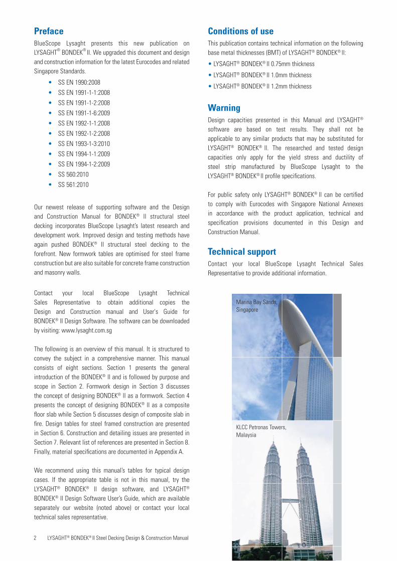
Marina Bay Sands, Singapore
KLCC Petronas Towers, Malaysia
2 LYSAGHT® BONDEK® II Steel Decking Design & Construction Manual

3 LYSAGHT® BONDEK® II Steel Decking Design & Construction Manual 3LYSAGHT® BONDEK® II Steel Decking Design & Construction Manual
1. Introducing LYSAGHT® BONDEK® II . . . . . . . . . . . . . . . . . . . . . . . 4
2. Purpose and scope of this publication. . . . . . . . . . . . . . . . . . . . . 6
3. Formwork design . . . . . . . . . . . . . . . . . . . . . . . . . . . . . . . . . . . . . . . 7 3.1 Introduction. . . . . . . . . . . . . . . . . . . . . . . . . . . . . . . . . . . . . . . . . . . 7 3.2 Recommended deflection limits. . . . . . . . . . . . . . . . . . . . . . . . . . . 7 3.3 Loads for design . . . . . . . . . . . . . . . . . . . . . . . . . . . . . . . . . . . . . . . 7 3.4 Use of formwork tables . . . . . . . . . . . . . . . . . . . . . . . . . . . . . . . . . 8 3.5 LYSAGHT® BONDEK® II maximum span tables . . . . . . . . . . . . . . 10
4. Composite slab design. . . . . . . . . . . . . . . . . . . . . . . . . . . . . . . . . . 13 4.1 Introduction. . . . . . . . . . . . . . . . . . . . . . . . . . . . . . . . . . . . . . . . . . 13 4.2 Design loads . . . . . . . . . . . . . . . . . . . . . . . . . . . . . . . . . . . . . . . . . 13 4.2.1 Strength load combinations . . . . . . . . . . . . . . . . . . . . . . 13 4.2.2 Serviceability load combinations . . . . . . . . . . . . . . . . . . 13 4.2.3 Superimposed dead load. . . . . . . . . . . . . . . . . . . . . . . . . 13 4.3 Design for strength. . . . . . . . . . . . . . . . . . . . . . . . . . . . . . . . . . . . 14 4.3.1 Negative bending regions . . . . . . . . . . . . . . . . . . . . . . . . 14 4.3.2 Positive bending regions . . . . . . . . . . . . . . . . . . . . . . . . . 14 4.4 Design for durability and serviceability . . . . . . . . . . . . . . . . . . . . 14 4.4.1 Exposure classification and cover. . . . . . . . . . . . . . . . . . 14 4.4.2 Deflections. . . . . . . . . . . . . . . . . . . . . . . . . . . . . . . . . . . . 14 4.4.3 Crack control . . . . . . . . . . . . . . . . . . . . . . . . . . . . . . . . . . 14 4.5 Detailing of conventional reinforcement . . . . . . . . . . . . . . . . . . . 15 4.6 Use of tables given in Section 6 . . . . . . . . . . . . . . . . . . . . . . . . . 16
5. Design for fire . . . . . . . . . . . . . . . . . . . . . . . . . . . . . . . . . . . . . . . . . 17 5.1 Introduction. . . . . . . . . . . . . . . . . . . . . . . . . . . . . . . . . . . . . . . . . . 17 5.2 Fire resistance periods . . . . . . . . . . . . . . . . . . . . . . . . . . . . . . . . . 17 5.3 Design for insulation and integrity . . . . . . . . . . . . . . . . . . . . . . . 17 5.4 Design for structural adequacy . . . . . . . . . . . . . . . . . . . . . . . . . . 17 5.4.1 Design loads . . . . . . . . . . . . . . . . . . . . . . . . . . . . . . . . . . 17 5.4.2 Design for strength . . . . . . . . . . . . . . . . . . . . . . . . . . . . . 17 5.5 Reinforcement for fire design . . . . . . . . . . . . . . . . . . . . . . . . . . . 18
6. Design tables - steel-framed construction . . . . . . . . . . . . . . . . 20 6.1 Use of design tables. . . . . . . . . . . . . . . . . . . . . . . . . . . . . . . . . 20 6.2 Interpretation of table solutions . . . . . . . . . . . . . . . . . . . . . . . 21 6.3 Single span tables (1kPa) . . . . . . . . . . . . . . . . . . . . . . . . . . . . . 22 6.4 Interior span tables (1kPa) . . . . . . . . . . . . . . . . . . . . . . . . . . . . 25 6.5 End span tables (1kPa) . . . . . . . . . . . . . . . . . . . . . . . . . . . . . . . 32 6.6 Single span tables (3kPa) . . . . . . . . . . . . . . . . . . . . . . . . . . . . . 38 6.7 Interior span tables (3kPa) . . . . . . . . . . . . . . . . . . . . . . . . . . . . 41 6.8 End span tables (3kPa) . . . . . . . . . . . . . . . . . . . . . . . . . . . . . . . 48
7. Construction and detailing . . . . . . . . . . . . . . . . . . . . . . . . . . . . . . 54 7.1 Safety . . . . . . . . . . . . . . . . . . . . . . . . . . . . . . . . . . . . . . . . . . . . 54 7.2 Care and storage before installation . . . . . . . . . . . . . . . . . . . . 54
7.3 Installation of BONDEK® II sheeting on-site . . . . . . . . . . . . . . 54 7.3.1 Propping. . . . . . . . . . . . . . . . . . . . . . . . . . . . . . . . . . . . . . 55 7.3.2 Laying. . . . . . . . . . . . . . . . . . . . . . . . . . . . . . . . . . . . . . . . 55 7.3.3 Interlocking of sheets . . . . . . . . . . . . . . . . . . . . . . . . . . . 55 7.3.4 Securing the sheeting platform. . . . . . . . . . . . . . . . . . . . 56 7.3.5 Installing BONDEK® II on steel frames . . . . . . . . . . . . . . 56 7.3.6 Installing BONDEK® II on brick supports . . . . . . . . . . . . . 57 7.3.7 Installing BONDEK® II on concrete frames . . . . . . . . . . . 58 7.3.8 Provision of construction and movement joints . . . . . . . 58 7.3.9 Fastening side-lap joints . . . . . . . . . . . . . . . . . . . . . . . . . 58 7.3.10 Cutting and fitting EDGEFORM . . . . . . . . . . . . . . . . . . . 58 7.3.11 Cutting of sheeting . . . . . . . . . . . . . . . . . . . . . . . . . . . . 60 7.3.12 Items embedded in slabs . . . . . . . . . . . . . . . . . . . . . . . 60 7.3.13 Holes in sheeting. . . . . . . . . . . . . . . . . . . . . . . . . . . . . . 61 7.3.14 Sealing. . . . . . . . . . . . . . . . . . . . . . . . . . . . . . . . . . . . . . 61 7.3.15 Inspection . . . . . . . . . . . . . . . . . . . . . . . . . . . . . . . . . . . 62 7.4 Positioning and support of reinforcement . . . . . . . . . . . . . . . . 62 7.4.1 Transverse reinforcement . . . . . . . . . . . . . . . . . . . . . . . . 63 7.4.2 Longitudinal reinforcement . . . . . . . . . . . . . . . . . . . . . . . 63 7.4.3 Trimmers . . . . . . . . . . . . . . . . . . . . . . . . . . . . . . . . . . . . . 63 7.5 Concrete . . . . . . . . . . . . . . . . . . . . . . . . . . . . . . . . . . . . . . . . . . 63 7.5.1 Specification . . . . . . . . . . . . . . . . . . . . . . . . . . . . . . . . . . 63 7.5.2 Concrete additives. . . . . . . . . . . . . . . . . . . . . . . . . . . . . . 63 7.5.3 Preparation of sheeting . . . . . . . . . . . . . . . . . . . . . . . . . . 63 7.5.4 Construction joints. . . . . . . . . . . . . . . . . . . . . . . . . . . . . . 63 7.5.5 Placement of concrete. . . . . . . . . . . . . . . . . . . . . . . . . . . 64 7.5.6 Curing. . . . . . . . . . . . . . . . . . . . . . . . . . . . . . . . . . . . . . . . 64 7.5.7 Prop removal . . . . . . . . . . . . . . . . . . . . . . . . . . . . . . . . . . 64 7.6 Finishing . . . . . . . . . . . . . . . . . . . . . . . . . . . . . . . . . . . . . . . . . . 64 7.6.1 Soffit and EDGEFORM finishes . . . . . . . . . . . . . . . . . . . . 64 7.6.2 Painting . . . . . . . . . . . . . . . . . . . . . . . . . . . . . . . . . . . . . . 65 7.6.3 Plastering. . . . . . . . . . . . . . . . . . . . . . . . . . . . . . . . . . . . . 65 7.6.4 Addition of fire protective coating . . . . . . . . . . . . . . . . . 66 7.7 Suspended ceilings & services . . . . . . . . . . . . . . . . . . . . . . . . 66 7.7.1 Plasterboard. . . . . . . . . . . . . . . . . . . . . . . . . . . . . . . . . . . 66 7.7.2 Suspended ceiling . . . . . . . . . . . . . . . . . . . . . . . . . . . . . . 66 7.7.3 Suspended services. . . . . . . . . . . . . . . . . . . . . . . . . . . . . 66 7.8 Fire stopping detailing . . . . . . . . . . . . . . . . . . . . . . . . . . . . . . . 67 7.8.1 At reinforced block walls . . . . . . . . . . . . . . . . . . . . . . . . 67 7.8.2 Fire collars . . . . . . . . . . . . . . . . . . . . . . . . . . . . . . . . . . . . 67 7.9 BONDEK® II in post tensioned concrete-framed construction . . . . . . 68 7.9.1 BONDEK ® II rib removal at PT anchor points or stressing pans . . . . . . . . . . . . . . . . . . . . . . . . . . . . . . . . . 68 7.9.2 Positioning of PT duct/cables in transverse direction . . 68 7.10 Architectural matters . . . . . . . . . . . . . . . . . . . . . . . . . . . . . . . . 68 7.11 Accessories . . . . . . . . . . . . . . . . . . . . . . . . . . . . . . . . . . . . . . . . 69
8. References. . . . . . . . . . . . . . . . . . . . . . . . . . . . . . . . . . . . . . . . . . . . . 70
Contents
The Star, SingaporeJEM, Singapore
4 LYSAGHT® BONDEK® II Steel Decking Design & Construction Manual
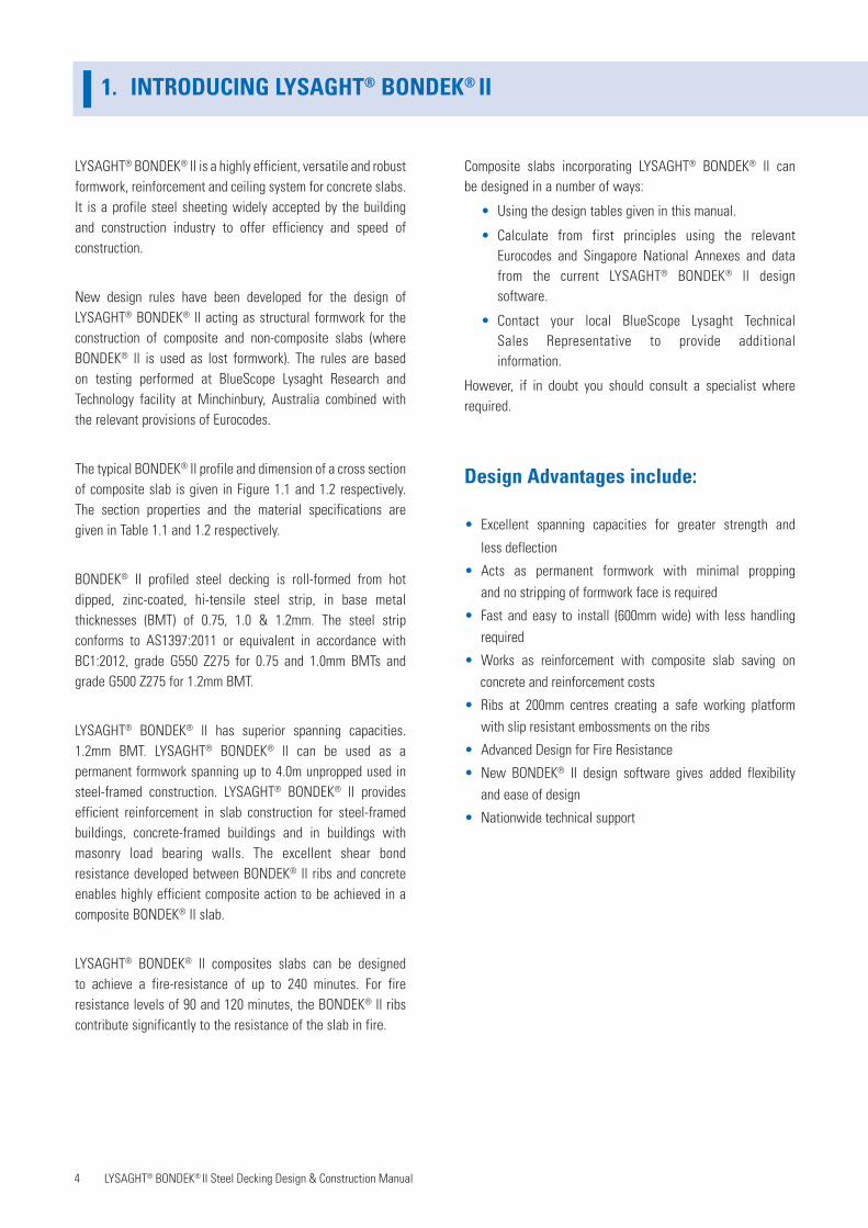
LYSAGHT® BONDEK® ll is a highly efficient, versatile and robust formwork, reinforcement and ceiling system for concrete slabs. It is a profile steel sheeting widely accepted by the building and construction industry to offer efficiency and speed of construction.
New design rules have been developed for the design of LYSAGHT® BONDEK® ll acting as structural formwork for the construction of composite and non-composite slabs (where BONDEK® ll is used as lost formwork). The rules are based on testing performed at BlueScope Lysaght Research and Technology facility at Minchinbury, Australia combined with the relevant provisions of Eurocodes.
The typical BONDEK® ll profile and dimension of a cross section of composite slab is given in Figure 1.1 and 1.2 respectively. The section properties and the material specifications are given in Table 1.1 and 1.2 respectively.
BONDEK® II profiled steel decking is roll-formed from hot dipped, zinc-coated, hi-tensile steel strip, in base metal thicknesses (BMT) of 0.75, 1.0 & 1.2mm. The steel strip conforms to AS1397:2011 or equivalent in accordance with BC1:2012, grade G550 Z275 for 0.75 and 1.0mm BMTs and grade G500 Z275 for 1.2mm BMT.
LYSAGHT® BONDEK® ll has superior spanning capacities. 1.2mm BMT. LYSAGHT® BONDEK® ll can be used as a permanent formwork spanning up to 4.0m unpropped used in steel-framed construction. LYSAGHT® BONDEK® ll provides efficient reinforcement in slab construction for steel-framed buildings, concrete-framed buildings and in buildings with masonry load bearing walls. The excellent shear bond resistance developed between BONDEK® ll ribs and concrete enables highly efficient composite action to be achieved in a composite BONDEK® ll slab.
LYSAGHT® BONDEK® ll composites slabs can be designed to achieve a fire-resistance of up to 240 minutes. For fire resistance levels of 90 and 120 minutes, the BONDEK® ll ribs contribute significantly to the resistance of the slab in fire.
1. INTRODUCING LYSAGHT® BONDEK® II
Composite slabs incorporating LYSAGHT® BONDEK® ll canbe designed in a number of ways:
• Using the design tables given in this manual.
• Calculate from first principles using the relevant Eurocodes and Singapore National Annexes and data from the current LYSAGHT® BONDEK® ll design software.
• Contact your local BlueScope Lysaght Technical Sales Representative to provide additional information.
However, if in doubt you should consult a specialist where required.
Design Advantages include:
• Excellent spanning capacities for greater strength and
less deflection
• Acts as permanent formwork with minimal propping and no stripping of formwork face is required
• Fast and easy to install (600mm wide) with less handling required
• Works as reinforcement with composite slab saving on concrete and reinforcement costs
• Ribs at 200mm centres creating a safe working platform with slip resistant embossments on the ribs
• Advanced Design for Fire Resistance
• New BONDEK® II design software gives added flexibility and ease of design
• Nationwide technical support

5 LYSAGHT® BONDEK® II Steel Decking Design & Construction Manual
Figure 1.1 LYSAGHT® BONDEK® ll profile
Table 1.1LYSAGHT® BONDEK® ll section properties
Thickness Yield Strength
Section Modulus
Area
Cross-sectional area of
BONDEK
Second Moment
Sheeting Elastic
CentroidMass Coverage
LYSAGHT® BONDEK® ll Structural Steel Decking Profile
BMT (mm) MPa Zx 103 mm3/m Ash (mm2/m) Ix 104 mm4/m dcb (mm) kg/m2 kg/m m2/t
0.75 550 12.50 1259 47.98 15.3 10.3 6.18 97.13
1.0 550 16.69 1678 64.08 15.5 13.6 8.14 73.71
1.2* 500 20.03 2014 76.90 15.5 16.2 9.71 61.79
LYSAGHT® BONDEK® ll structural steel profile
LYSAGHT® BONDEK® II STRUCTURAL STEEL DECKING SYSTEM
TYPICAL UNPROPPED SPAN 2.6M - 3.8M
*Subject to availability

6 LYSAGHT® BONDEK® II Steel Decking Design & Construction Manual
b
dctc
D 32
52
SHEETINGELASTIC
CENTROID
dcb tbm (BMT)
29
51
13200 200 200
Cover width 600
hr = 5432
CENTROID OF ALLNEGATIVE REINFORCEMENT Embossments on ribs
Sheet width 630
Bottom tensile (positive) reinforcement A+, mid
Concrete
BONDEK
PanFlute
Negative reinforcementfor flexure and
crack control (A-st)
Shrinkage andtemperaturereinforcement -A1 mesh Top location
(continuous spans)
Bottom location (single spans) -A1 mesh
Figure 1.2BONDEK® II dimensions (2 sheets shown)
(Fire reinforcement is not shown, see Chapter 5)
2. PURPOSE AND SCOPE OF THIS PUBLICATION
As stated in the Preface and Introduction, the purpose of this Manual is to facilitate the design of LYSAGHT® BONDEK® ll in its use as formwork (with and without propping) and within concrete slabs for both steel-framed and concrete-framed buildings. It has been developed in accordance with the latest Eurocodes and Singapore National Annexes. The Manual includes the following information:
• Formwork Design and Spanning Tables (Section 3)
• Composite Slab Design (Section 4)
• Design for Fire (Section 5)
• Design Tables – Steel-framed construction (Section 6)
• Construction and Detailing (Section 7)
Section 6 gives tabulated solutions for composite slabs in typical design situations.
Use this Manual's tables for typical design cases. If the appropriate table is not in this Manual, try the LYSAGHT® BONDEK® ll design software, which is available from the LYSAGHT® website, at: www.lysaght.com.sg, to assist in designing other cases. If none of these options provides a suitable solution, contact your local BlueScope Lysaght Technical Sales Representative to provide additional information.
The information presented by the tabulated solutions of Sections 3 and 6 is intended for guidance only. This information is to be used only in conjunction with a consultingstructural engineer.

7 LYSAGHT® BONDEK® II Steel Decking Design & Construction Manual
3. FORMWORK DESIGN
3.1 Introduction
The installation of LYSAGHT® BONDEK® ll follows traditional methods for quick and easy installation. It is available in long lengths so large areas can be quickly and easily covered to form a safe working platform during construction.LYSAGHT® BONDEK® ll provides a cover width of 600 mm, which allows quick installation.
Formwork design calculations are covered in this section, geometric layout considerations are generally covered in Section 7 (Construction and Detailing).
Our design tables may be used to detail BONDEK® ll acting as structural formwork, provided the following conditionsare satisfied.
3.2 Recommended deflection limits N.A.2.15 to SS EN 1994-1-1:2009 defines suitable deflection limits for formwork. In addition, we recommend a deflection limit of L/180 for the design of composite slabs in which good general alignment is required, so that the soffit has a good visual quality when viewed as a whole.
We consider span/130 to be a reasonable maximumdeflection limit appropriate for profile steel sheeting in situations where visual quality is not significant.
The design rules presented may be used for deflection limits other than those stated above however, for deflection greater than span/130, you may contact our information service.
3.3 Loads for design
LYSAGHT® BONDEK® ll shall be designed as formwork for two stages of construction according to SS EN 1991-1-6:2009.
Stage I
Prior to the placement of the concrete:
• During handling and erection of the formwork; and
• Once the formwork is erected but prior to the placement of the concrete.
Loads:
• Self weight of formwork
• Construction load (workmen and equipment)
Qca = 1kPa according to (N.A. 2.12 to SS EN 1991-1-6:2009)
• Construction (storage) load Qcb should not exceed 1kPa. Use BONDEK® ll design software for higher loads.
Stage II
During placement of the concrete up until the concrete has set (until fck reaches 20MPa and concrete is able to act flexurally to support additional loads such as stacked materials).
NOTE: No loads from stacked materials are allowed until the concrete has set.
• Different pattern loading shall be considered, including when one formwork span only is loaded - with live loads, loads due to stacked materials and wet
Loads:
• Construction loads during concrete cast Qca = 0.75kPa according to (N.A. 2.13 to SS EN 1991-1-6:2009)
• Self weight of concrete and formwork
• Mounding of concrete = 0.75kPa over an area of 3.0 x 3.0m and zero over remainder
concrete.
8 LYSAGHT® BONDEK® II Steel Decking Design & Construction Manual
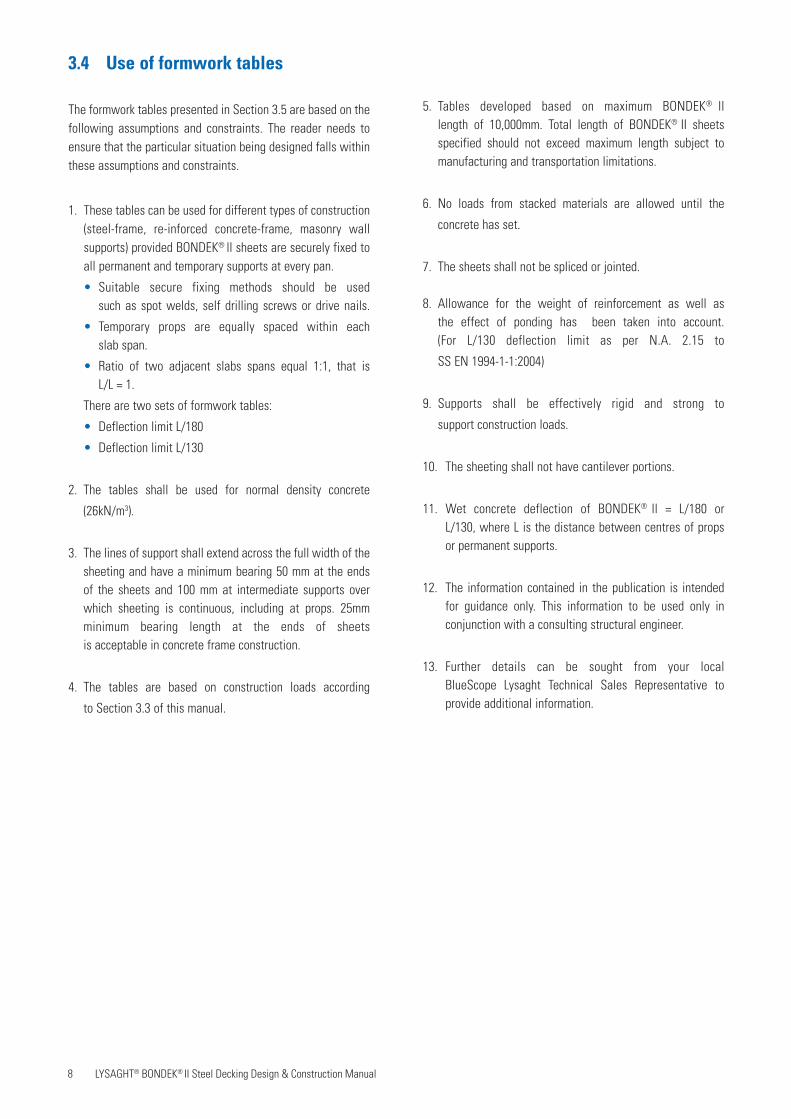
3.4 Use of formwork tables
The formwork tables presented in Section 3.5 are based on the following assumptions and constraints. The reader needs to ensure that the particular situation being designed falls within these assumptions and constraints.
1. These tables can be used for different types of construction (steel-frame, re-inforced concrete-frame, masonry wall supports) provided BONDEK® ll sheets are securely fixed to all permanent and temporary supports at every pan.
• Suitable secure fixing methods should be used such as spot welds, self drilling screws or drive nails.
• Temporary props are equally spaced within each slab span.
• Ratio of two adjacent slabs spans equal 1:1, that is L/L = 1.
There are two sets of formwork tables:
• Deflection limit L/180
• Deflection limit L/130
2. The tables shall be used for normal density concrete
(26kN/m3).
3. The lines of support shall extend across the full width of the sheeting and have a minimum bearing 50 mm at the ends of the sheets and 100 mm at intermediate supports over which sheeting is continuous, including at props. 25mm minimum bearing length at the ends of sheets is acceptable in concrete frame construction.
4. The tables are based on construction loads according
to Section 3.3 of this manual.
5. Tables developed based on maximum BONDEK® ll length of 10,000mm. Total length of BONDEK® II sheets specified should not exceed maximum length subject to manufacturing and transportation limitations.
6. No loads from stacked materials are allowed until the
concrete has set.
7. The sheets shall not be spliced or jointed.
8. Allowance for the weight of reinforcement as well as the effect of ponding has been taken into account. (For L/130 deflection limit as per N.A. 2.15 to
SS EN 1994-1-1:2004)
9. Supports shall be effectively rigid and strong to
support construction loads.
10. The sheeting shall not have cantilever portions.
11. Wet concrete deflection of BONDEK® ll = L/180 or L/130, where L is the distance between centres of props or permanent supports.
12. The information contained in the publication is intended for guidance only. This information to be used only in conjunction with a consulting structural engineer.
13. Further details can be sought from your local BlueScope Lysaght Technical Sales Representative to provide additional information.
9 LYSAGHT® BONDEK® II Steel Decking Design & Construction Manual
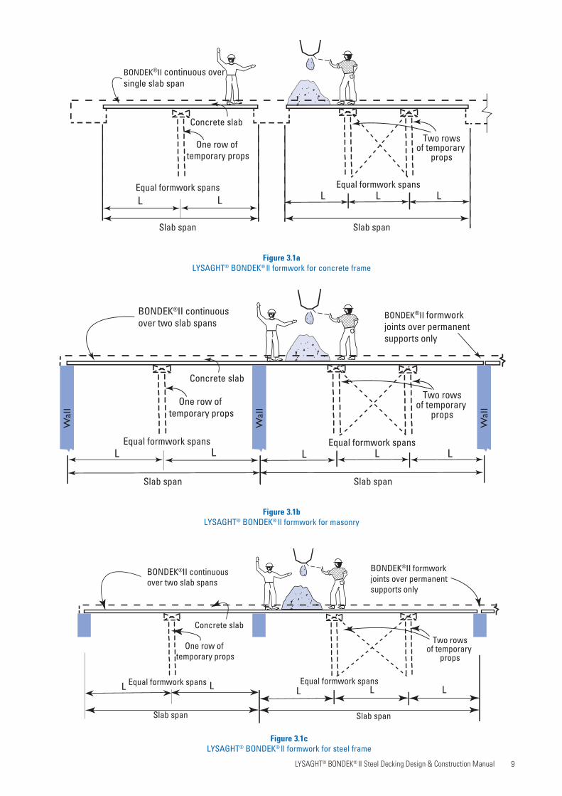
Figure 3.1a LYSAGHT® BONDEK® ll formwork for concrete frame
Equal formwork spans
Slab span
BONDEK®II continuous oversingle slab span
Concrete slab
Two rowsof temporary
props
Slab span
Equal formwork spans
One row of temporary props
L L L L L
Figure 3.1b LYSAGHT® BONDEK® ll formwork for masonry
Equal formwork spans
Slab span
BONDEK®II formwork joints over permanentsupports only
Concrete slab
Two rowsof temporary
props
Slab span
One row of temporary props
L L L L L
Wal
l
Wal
l
Wal
l
BONDEK®II continuousover two slab spans
Equal formwork spans
Figure 3.1c LYSAGHT® BONDEK® ll formwork for steel frame
Equal formwork spans
Slab span
BONDEK®II formwork joints over permanentsupports only
Concrete slab
Two rowsof temporary
props
Slab span
One row of temporary props
L L L L L
BONDEK®II continuous over two slab spans
Equal formwork spans

10 LYSAGHT® BONDEK® II Steel Decking Design & Construction Manual
3.5 LYSAGHT® BONDEK® II Formwork/ slab span tables
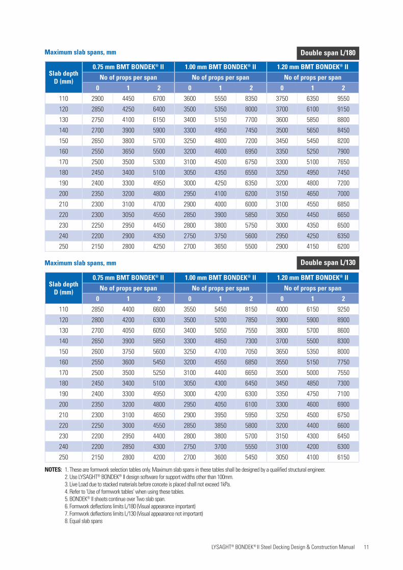
Maximum slab spans, mm
Maximum slab spans, mm
NOTES: 1. These are formwork selection tables only. Maximum slab spans in these tables shall be designed by a qualified structural engineer. 2. Use LYSAGHT® BONDEK® II design software for support widths other than 100mm. 3. Live Load due to stacked materials before concete is placed shall not exceed 1kPa. 4. Refer to 'Use of formwork tables' when using these tables. 5. BONDEK® II sheets continue over single slab span. 6. Formwork deflections limits L/180 (Visual appearance important). 7. Formwork deflections limits L/130 (Visual appearance not important).
Single span L/180
Single span L/130
Slab depthD (mm)
0.75 mm BMT BONDEK® II 1.00 mm BMT BONDEK® II 1.20 mm BMT BONDEK® II
No of props per span No of props per span No of props per span
0 1 2 0 1 2 0 1 2
110 2300 4450 6700 2550 5550 8350 2700 6350 9550
120 2250 4250 6400 2450 5350 8000 2600 6100 9150
130 2200 4100 6150 2400 5150 7700 2550 5850 8800
140 2150 3900 5900 2350 4950 7450 2500 5650 8450
150 2100 3800 5700 2300 4800 7200 2450 5450 8250
160 2050 3650 5500 2250 4600 6950 2400 5250 7900
170 2000 3500 5300 2200 4500 6750 2350 5100 7650
180 1950 3400 5100 2150 4350 6550 2300 4950 7450
190 1900 3300 4950 2100 4250 6350 2250 4800 7200
200 1850 3200 4800 2100 4100 6200 2200 4650 7000
210 1800 3100 4700 2050 4000 6000 2150 4550 6850
220 1750 3050 4550 2000 3900 5850 2150 4450 6650
230 1750 2950 4450 1950 3800 5750 2100 4350 6500
240 1700 2950 4350 1950 3750 5600 2100 4250 6350
250 1650 2800 4250 1900 3650 5500 2050 4150 6200
Slab depthD (mm)
0.75 mm BMT BONDEK® II 1.00 mm BMT BONDEK® II 1.20 mm BMT BONDEK® II
No of props per span No of props per span No of props per span
0 1 2 0 1 2 0 1 2
110 2450 4400 6600 2700 5450 8150 2850 6200 9200
120 2400 4200 6300 2650 5250 7850 2800 5950 8900
130 2350 4050 6050 2600 5050 7550 2750 5750 8550
140 2300 3900 5800 2550 4850 7300 2700 5550 8250
150 2250 3750 5600 2500 4700 7050 2650 5350 8000
160 2200 3600 5400 2450 4550 6850 2600 5200 7750
170 2150 3500 5250 2400 4450 6650 2550 5050 7500
180 2100 3400 5100 2350 4300 6450 2500 4900 7300
190 2100 3300 4950 2300 4200 6300 2450 4750 7100
200 2050 3200 4800 2250 4100 6100 2400 4600 6900
210 2000 3100 4650 2250 4000 5950 2350 4500 6750
220 1950 3000 4550 2200 3900 5800 2350 4400 6600
230 1950 2950 4400 2200 3800 5700 2300 4300 6450
240 1900 2850 4300 2150 3700 5550 2300 4200 6300
250 1900 2800 4200 2100 3600 5450 2250 4100 6150
11 LYSAGHT® BONDEK® II Steel Decking Design & Construction Manual
Maximum slab spans, mm
Maximum slab spans, mm
NOTES: 1. These are formwork selection tables only. Maximum slab spans in these tables shall be designed by a qualified structural engineer. 2. Use LYSAGHT® BONDEK® II design software for support widths other than 100mm. 3. Live Load due to stacked materials before concete is placed shall not exceed 1kPa. 4. Refer to 'Use of formwork tables' when using these tables. 5. BONDEK® II sheets continue over Two slab span. 6. Formwork deflections limits L/180 (Visual appearance important) 7. Formwork deflections limits L/130 (Visual appearance not important) 8. Equal slab spans
Double span L/180
Double span L/130
Slab depthD (mm)
0.75 mm BMT BONDEK® II 1.00 mm BMT BONDEK® II 1.20 mm BMT BONDEK® II
No of props per span No of props per span No of props per span
0 1 2 0 1 2 0 1 2
110 2900 4450 6700 3600 5550 8350 3750 6350 9550
120 2850 4250 6400 3500 5350 8000 3700 6100 9150
130 2750 4100 6150 3400 5150 7700 3600 5850 8800
140 2700 3900 5900 3300 4950 7450 3500 5650 8450
150 2650 3800 5700 3250 4800 7200 3450 5450 8200
160 2550 3650 5500 3200 4600 6950 3350 5250 7900
170 2500 3500 5300 3100 4500 6750 3300 5100 7650
180 2450 3400 5100 3050 4350 6550 3250 4950 7450
190 2400 3300 4950 3000 4250 6350 3200 4800 7200
200 2350 3200 4800 2950 4100 6200 3150 4650 7000
210 2300 3100 4700 2900 4000 6000 3100 4550 6850
220 2300 3050 4550 2850 3900 5850 3050 4450 6650
230 2250 2950 4450 2800 3800 5750 3000 4350 6500
240 2200 2900 4350 2750 3750 5600 2950 4250 6350
250 2150 2800 4250 2700 3650 5500 2900 4150 6200
Slab depthD (mm)
0.75 mm BMT BONDEK® II 1.00 mm BMT BONDEK® II 1.20 mm BMT BONDEK® II
No of props per span No of props per span No of props per span
0 1 2 0 1 2 0 1 2
110 2850 4400 6600 3550 5450 8150 4000 6150 9250
120 2800 4200 6300 3500 5200 7850 3900 5900 8900
130 2700 4050 6050 3400 5050 7550 3800 5700 8600
140 2650 3900 5850 3300 4850 7300 3700 5500 8300
150 2600 3750 5600 3250 4700 7050 3650 5350 8000
160 2550 3600 5450 3200 4550 6850 3550 5150 7750
170 2500 3500 5250 3100 4400 6650 3500 5000 7550
180 2450 3400 5100 3050 4300 6450 3450 4850 7300
190 2400 3300 4950 3000 4200 6300 3350 4750 7100
200 2350 3200 4800 2950 4050 6100 3300 4600 6900
210 2300 3100 4650 2900 3950 5950 3250 4500 6750
220 2250 3000 4550 2850 3850 5800 3200 4400 6600
230 2200 2950 4400 2800 3800 5700 3150 4300 6450
240 2200 2850 4300 2750 3700 5550 3100 4200 6300
250 2150 2800 4200 2700 3600 5450 3050 4100 6150

12 LYSAGHT® BONDEK® II Steel Decking Design & Construction Manual
NOTES: 1. These are formwork selection tables only. Maximum slab spans in these tables shall be designed by a qualified structural engineer. 2. Use LYSAGHT® BONDEK® II design software for support widths other than 100mm. 3. Live Load due to stacked materials before concete is placed shall not exceed 1kPa. 4. Refer to 'Use of formwork tables' when using these tables. 5. Equal slab spans. 6. BONDEK® II sheets continue over Three slab span. 7. Formwork deflections limits L/180 (Visual appearance important). 8. Formwork deflections limits L/130 (Visual appearance not important).
Maximum slab spans, mm
Maximum slab spans, mm
Triple span L/180
Triple span L/130
Slab depthD (mm)
0.75 mm BMT BONDEK® II 1.00 mm BMT BONDEK® II 1.20 mm BMT BONDEK® II
No of props per span No of props per span No of props per span
0 1 2 0 1 2 0 1 2
110 2900 4450 6700 3350 5550 8350 3550 6350 9550
120 2850 4250 6400 3250 5350 8000 3450 6100 9150
130 2750 4100 6150 3150 5150 7700 3350 5850 8800
140 2700 3900 5900 3050 4950 7450 3250 5650 8450
150 2650 3800 5700 3000 4800 7200 3200 5450 8200
160 2550 3650 5500 2950 4600 6950 3100 5250 7900
170 2500 3500 5300 2900 4500 6750 3050 5100 7650
180 2450 3400 5100 2800 4350 6550 3000 4950 7450
190 2400 3300 4950 2750 4250 6350 2950 4800 7200
200 2350 3200 4800 2700 4100 6200 2900 4650 7000
210 2300 3100 4700 2650 4000 6000 2850 4550 6850
220 2300 3050 4550 2600 3900 5850 2800 4450 6650
230 2250 2950 4450 2550 3800 5750 2750 4350 6500
240 2200 2900 4350 2500 3750 5600 2700 4250 6350
250 2150 2800 4250 2450 3650 5500 2650 4150 6200
Slab depthD (mm)
0.75 mm BMT BONDEK® II 1.00 mm BMT BONDEK® II 1.20 mm BMT BONDEK® II
No of props per span No of props per span No of props per span
0 1 2 0 1 2 0 1 2
110 2850 4400 6600 3500 5450 8150 3700 6150 9250
120 2750 4200 6300 3450 5200 7850 3650 5900 8900
130 2700 4050 6050 3350 5050 7550 3550 5700 8600
140 2650 3900 5800 3300 4850 7300 3500 5500 8300
150 2550 3750 5600 3200 4700 7050 3400 5350 8000
160 2500 3600 5400 3150 4550 6850 3350 5150 7750
170 2450 3500 5250 3100 4400 6650 3300 5000 7550
180 2400 3400 5100 3050 4300 6450 3250 4850 7300
190 2350 3300 4950 3000 4200 6300 3200 4750 7100
200 2350 3200 4800 2950 4050 6100 3150 4600 6950
210 2300 3100 4650 2900 3950 5950 3100 4500 6750
220 2250 3000 4550 2850 3850 5800 3050 4400 6600
230 2200 2950 4400 2800 3800 5700 3000 4300 6450
240 2200 2850 4300 2750 3700 5550 2950 4200 6300
250 2150 2800 4200 2700 3600 5450 2950 4100 6150
13 LYSAGHT® BONDEK® II Steel Decking Design & Construction Manual
4. COMPOSITE SLAB DESIGN
4.1 Introduction
Considerable research into the behaviour of composite slabs has been performed in the past years. The efficiency of the composite slab depends on the composite action between the steel sheeting and concrete slab. The experiments indicated that the shear bond strength at the interface between the steel sheet and the surrounding concrete is the key factor in determining the behaviour of composite slabs.
The adhesion bond between the sheeting and the concrete can play a part in this behaviour. However, following the breakdown of the adhesion bond, slip is resisted by mechanical interlock and friction developed between the steel sheeting and the surrounding concrete. The mechanical interlock and friction depend upon the shape of the rib, thickness of the sheet and size and frequency of the embossments.
This chapter explains the parameters upon which our design tables are based. Solutions to your design problems may be obtained by direct reference to the current version of our LYSAGHT® BONDEK® ll design software.
The design solutions are based on linear elastic analysis according to SS EN 1994-1-1:2009 Section 9.7.3 (7) and partial shear connection theory. Data about composite performance of LYSAGHT® BONDEK® ll slabs have been obtained fromfull-scale slab tests.
Use the appropriate LYSAGHT® design software in other cases (concrete grades, environmental classifications, fire ratings, moment redistribution, etc.).
The tables provide solutions for steel-frame (or other narrow supports like masonry walls) provided the following conditions are satisfied.
4.2 Design loads
4.2.1 Strength load combinations
For strength calculations, design loads for both propped and unpropped construction shall be based on the followingload combinations.
Load combinations and pattern loading shall be considered according to:
• SS EN 1991-1-1:2008 Section 6.2.1• Table NA A1.2 (B) to SS EN 1990:2008 Fd = 1.35 Gk + 1.5 Qk where Gk = (Gc + Gsh + Gsdl)where Gc = self weight of concrete;
Gsh = self weight of sheeting;
Gsdl = superimposed dead load (partitions, floor tiles, etc.)Fd = Design value of an actionQk = Characteristic value of a single variable actionGk = Characteristic of a permanent action
4.2.2 Serviceability load combinations
Our load tables are based on deflections due to loading applied to the composite slab according to:
• SS EN 1992-1-1:2008 Sections 7.4.3; 7.4.1• SS EN 1994-1-1:2009 Section 9.8.2• NA. 2.2.6 to SS EN 1990:2008
Crack control is based on:
• SS EN 1992-1-1:2008 Section 7.3.4• Table NA. 4 to SS EN 1992-1-1:2008
Fd = Gk +ψ2 Qkψ2= Factor for permanent value of a variable action per
SS EN 1990:2008 Table A1.1
4.2.3 Superimposed dead load
The maximum superimposed dead load (Gsdl) assumed in our design tables is 1.0 kPa and 3.0kPa. UseLYSAGHT® BONDEK® ll design software for other Gsdl loads.
14 LYSAGHT® BONDEK® II Steel Decking Design & Construction Manual
4.3 Design for strength
4.3.1 Negative bending regions
a) Negative bending strength
For the bending strength design in negative moment regions, the presence of the sheeting in the slab is ignored and the slab shall be designed as conventional reinforced concrete solid slab. For this purpose, use the provisions ofSS EN 1992-1-1:2008
b) Shear strength
The strength of a slab in shear shall be designed as per
the guidelines outlined in: • SS EN 1992-1-1:2008 Clause 6.2.2
• Table NA.1 to SS EN 1992-1-1:2008The Design tables are based on these guidelines.
4.3.2 Positive bending regions
a) Positive bending strength
Positive bending capacity shall be calculated as perSS EN 1994-1-1:2009 Clause 9.7.2. It takes into consideration partial shear connection theory and the design tables have been developed in accordance with it.
b) Shear strength
The positive shear capacity can be calculated as perSS EN 1992-1-1:2008 Clause 6.2.2. Partial shear connectiontheory is used for the contribution of BONDEK® ll.
4.4 Design for durability and serviceability
4.4.1 Exposure classification and cover
The minimum concrete cover (c) to reinforcing steel, measured from the slab top face is 25mm coresponding to Exposure Classes up to XC3 and Structural Class up to S4. UseBONDEK® ll software for all other classifications.
4.4.2 Deflections
Deflections are calculated using method given in:
• SS EN 1992-1-1:2008 Sections 7.4.3; 7.4.1
• SS EN 1994-1-1:2009 Section 9.8.2 (5)
4.4.3 Crack control
The Design tables have been developed based on crack control calculating crack widths according to:
• SS EN 1992-1-1:2008 Section 7.3.4
• Table NA.4 to SS EN 1992-1-1:2008
Fd = Gk + ψ2 Qk
15 LYSAGHT® BONDEK® II Steel Decking Design & Construction Manual
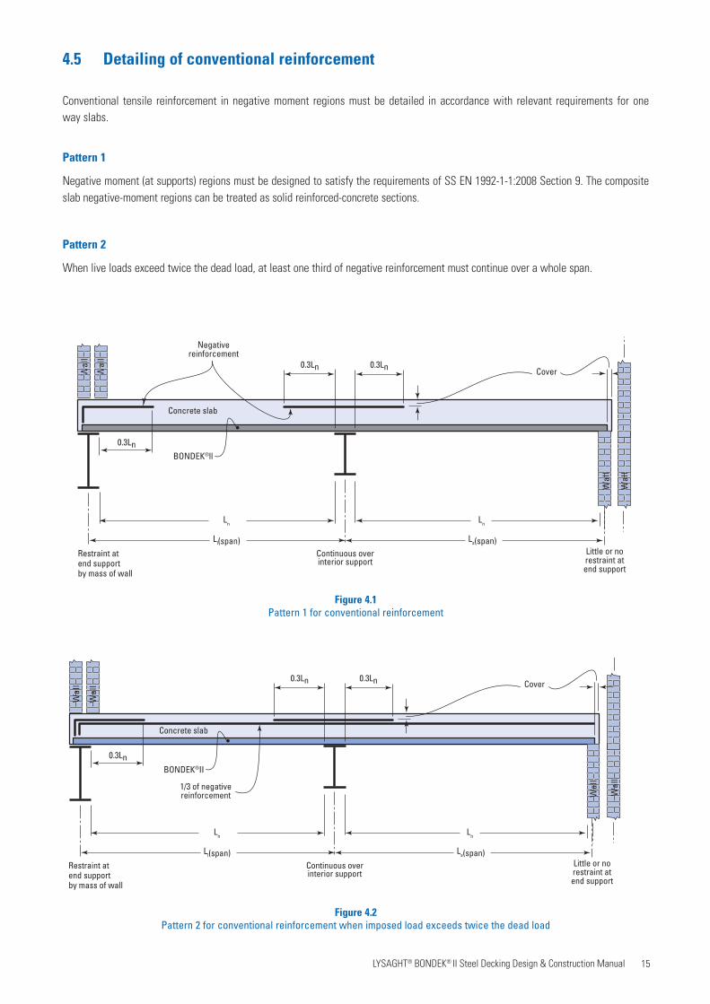
Figure 4.1Pattern 1 for conventional reinforcement
Figure 4.2 Pattern 2 for conventional reinforcement when imposed load exceeds twice the dead load
Little or norestraint atend support
0.3Ln
Negativereinforcement
BONDEK®ll
Ln Ln
Restraint atend supportby mass of wall
Continuous overinterior support
0.3Ln
0.3Ln
Ls(span)
Concrete slab
Wal
l
CoverWal
l
Ll(span)
Wal
l
Wal
l
Little or norestraint atend support
0.3Ln
BONDEK®II
Ln Ln
Restraint atend supportby mass of wall
Continuous overinterior support
0.3Ln
0.3Ln
Ls(span)
Concrete slab
Wal
l
Cover
Wal
l
Ll(span)
1/3 of negativereinforcement W
all
Wal
l
Wal
l
Wal
l
4.5 Detailing of conventional reinforcement
Conventional tensile reinforcement in negative moment regions must be detailed in accordance with relevant requirements for oneway slabs.
Pattern 1
Negative moment (at supports) regions must be designed to satisfy the requirements of SS EN 1992-1-1:2008 Section 9. The composite slab negative-moment regions can be treated as solid reinforced-concrete sections.
Pattern 2
When live loads exceed twice the dead load, at least one third of negative reinforcement must continue over a whole span.
16 LYSAGHT® BONDEK® II Steel Decking Design & Construction Manual
4.6 Use of tables given in Section 6
The design solutions given in the tables presented inSection 6 is based on the design principles given in this section and the following assumptions and constraints. Other constraints are stated in Section 6.1. The reader needs to ensure that the particular situation being designed falls within these assumptions and constraints.
1. The concrete shall satisfy the requirements of SS EN 1992-1-1:2008 Section 3.1.
2. The lines of support extend across the full width of the sheeting and have a minimum bearing of 50mm at the ends of the sheets, and 100mm minimum at intermediate supports over which sheeting is continuous.
3. Spans are equal.
4. The slab has a uniform cross-section.
5. The design loads for serviceability and strength design must be uniformly-distributed and static in nature.
6. The bending moments at the supports are only caused by the action of vertical loads applied to the slab.
7. The geometry of the steel sheeting profile must conform to the dimensions and tolerances shown on our production drawings. Sheeting with embossments less than the specified lower characteristic value shall not be used compositely unless the value of longitudinal shear resistance is revised.
8. Material and construction requirements for conventional reinforcing steel shall be in accordance with:
• SS EN 1992-1-1:2008 Section 3.2
• SS 561:2010 Class B
• SS 560:2010 Class B
9. BONDEK® ll shall not be spliced, lapped or joined longitudinally in any way.
10. The permanent support lines shall extend across the full width of the slab.
11. Composite action shall be assumed to exist between the steel sheeting and the concrete once the concrete in the slab has attained a compressive strength of 20MPa, that is ƒck ≥ 20MPa. Prior to the development of composite action during construction, potential damage to the shear connection shall be avoided; and no loads from stacked materials are allowed.
12. Detailing of conventional tensile reinforcement over negative moment regions shall be arranged in accordance with the Figures 4.1 and 4.2. Refer to SS EN 1992-1-1:2008 Section 9 for more information on detailing of tensile reinforcement in one-way slab.
13. Only LYSAGHT® BONDEK® ll profiles can be used with this manual. High design value of longitudinal shear strength of composite slab, τu,Rd , responsible for composite performance are achieved due to the advanced features of LYSAGHT® BONDEK® ll.
17 LYSAGHT® BONDEK® II Steel Decking Design & Construction Manual
5. DESIGN FOR FIRE
5.2 Fire resistance periods
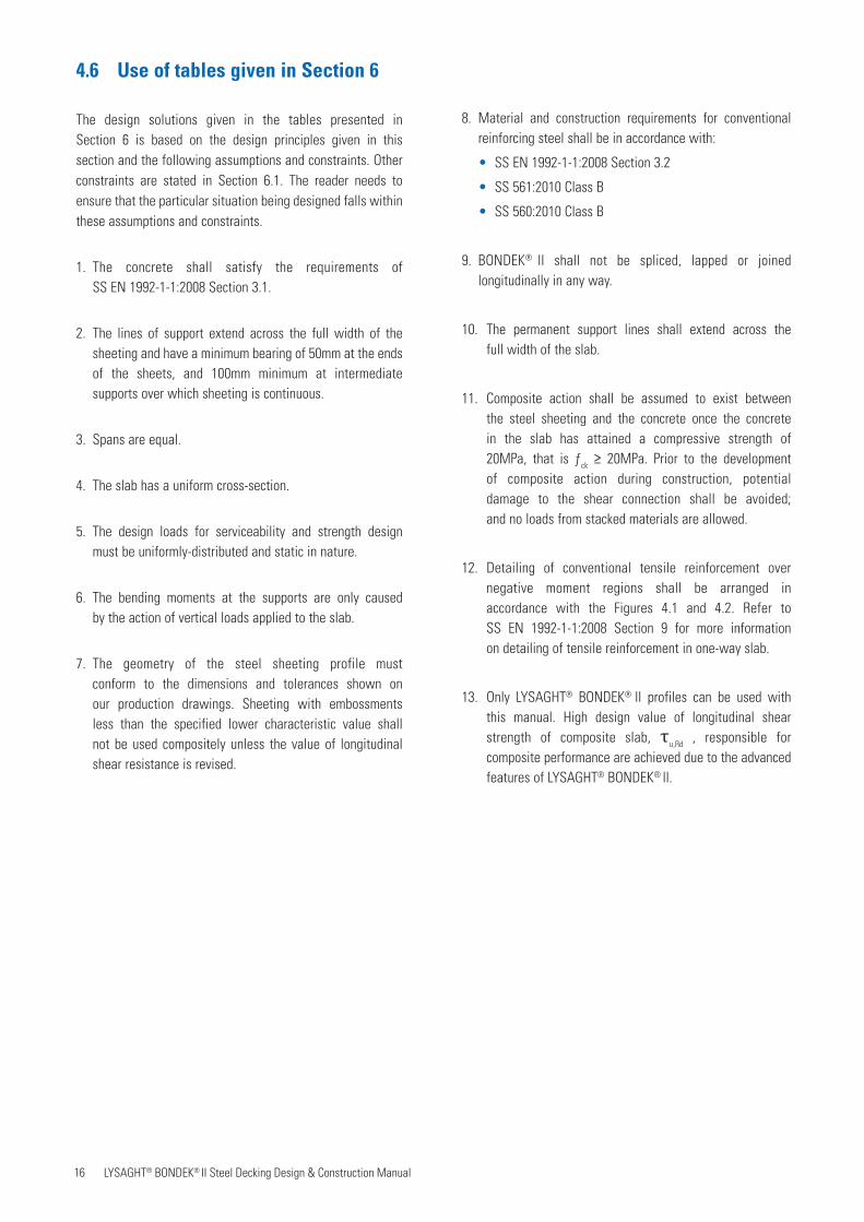
Five fire cases, 60, 90, 120, 180 and 240 minutes, are considered. In each fire case the fire resistance periods for structural adequacy, integrity and insulation are taken to be equal duration. Fire resistance period of 90 minutes and 120 minutes are provided in the design tables. It is recommended to use LYSAGHT® BONDEK® ll design software for fire resistance period up to four hours and alternative locations for fire reinforcement.
5.3 Design for insulation and integrity
Minimum required overall depth, D of BONDEK® ll slabs for insulation and integrity for various fire resistance periods is given in Table 5.1.
5.4. Design for structural adequacy
5.4.1 Design loads
Accidental Load Combinations according to NA 2.7 to
SS EN 1992-1-2:2008 Section 4.3.1 are used, Fd = Gk + ψ1 Qk.
ψ1= Factor for permanent value of a variable action per
SS EN 1990:2008 Table A1.1
5.4.2 Design for strength
In any specific design of a composite floor slab exposed to fire, it is essential the strength reduction factors account for the adverse effect of elevated temperatures on the mechanical properties of concrete and steel as well as a strength of shear bond capacity. The strength and structural adequacy must be checked in all potentially critical cross-sections for the given period of fire exposure considering the strengthreduction factors.
No additional fire reinforcement is normally necessary for typical BONDEK®ll composite slabs with fire resistance up to 90 minutes. Small amounts fire reinforcement may be necessary for 120 minutes fire resistance.
Table 5.1
5.1 Introduction
During the design of composite floor slabs exposed to fire, it is essential to take into account the effect of elevated temperatures on the material properties. The composite slabs should be assessed with respect to structural adequacy, thermal insulation and integrity. The minimum required thickness of composite slab to satisfy the insulation and integrity criterion is presented in Section 5.3. Design of slabs for the structural adequacy is presented in Section 5.4.
This Section discusses the parameters relating to the exposure of the soffit to fire, upon which our design tables are based. Solutions to your design problems may be obtained by direct reference to either our design tables, or ourLYSAGHT® BONDEK® ll design software. Software will give more economical results. BONDEK® ll composite slabs are designed based on SS EN 1994-1-2:2009 and Advanced Calculation Models supplimented with test data and thermal response modelling.
Our fire design tables may be used to detail BONDEK® ll composite slabs when the soffit is exposed to fire provided the following conditions are satisfied:
1. The composite slab acts as a one-way element spanning in the direction of the sheeting ribs for both room temperature and fire conditions.
2. The fire design load is essentially uniformly distributed and static in nature
3. Transverse reinforcement for the control of cracking due to shrinkage and temperature effects is provided.
4. Adequate detailing of slab jointing, edges, slab holes and cavities (for penetrating, embedded or encased services) to provide the appropriate fire resistance period. Alternatively the local provision of suitable protection (such as fire spray material) will be necessary.
5. Reinforcement conforms to Section 5.5 of this manual.
Fire resistance period
MinutesNormal density
concrete D (mm)
60 90
90 110
120 125
180 150
240 170
18 LYSAGHT® BONDEK® II Steel Decking Design & Construction Manual
Figure 5.1Details of reinforcement for fire design
BONDEK®II
Concrete Mesh
d – Dxb xb
dct
A–st A–
st.f
BONDEK®II
MeshConcrete
d +
Dxb xbyb
A–st
A+st.f
Fire Detail 1
Fire Detail 2
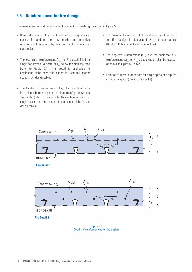
5.5 Reinforcement for fire design
The arrangement of additional fire reinforcement for fire design is shown in Figure 5.1.
• Some additional reinforcement may be necessary in some cases, in addition to any mesh and negative reinforcement required by our tables for composite slab design.
• The location of reinforcement A-st.f for Fire detail 1 is in a single top layer at a depth of dct below the slab top face (refer to Figure 5.1). This detail is applicable to continuous slabs only, this option is used for interior spans in our design tables.
• The location of reinforcement A+st.f for Fire detail 2 is in a single bottom layer at a distance of yb above the slab soffit (refer to Figure 5.1). This option is used for single spans and end spans of continuous slabs in our design tables.
• The cross-sectional area of the additional reinforcement for fire design is designated A+st.f in our tables (B500B with bar diameter = 12mm or less).
• The negative reinforcement (A-st) and the additional fire reinforcement (A+st.f or A-st.f as applicable), shall be located as shown in Figure 5.1 & 5.2.
• Location of mesh is at bottom for single spans and top for continuous spans. (See also Figure 1.2)

19 LYSAGHT® BONDEK® II Steel Decking Design & Construction Manual
BONDEK®ll
Concrete
xbxb
20
50
Permissible zone forlongitudinal fire reinforcement A+
st.f
yb
Figure 5.2Permissible zone for location of longitudinal fire reinforcement for Fire Detail 2.
The longitudinal bars which make up A+st.f should be
located within the zone shown in Figure 5.2.
xb = 85 mm minimum
yb = 60 mm average
NOTES:
1. Fire option 1 (Top location of additional fire reinforcement) is used in
Fire option 2 (Bottom) is used in design tables for simple and end spans.
2. Recommended bottom location of fire reinforcement is chosen for practical reasons (to place fire bars on transverse bars laid on top of Bondek® ll ribs). Lower location of fire bars with cover down to 25mm from soffit may give more economical results - please consult your local BlueScope Lysaght Technical Sales representative. Design tables are based on location as shown above in Figure 5.2.
design tables for interior spans.
20 LYSAGHT® BONDEK® II Steel Decking Design & Construction Manual
6. DESIGN TABLES - STEEL-FRAMED CONSTRUCTION
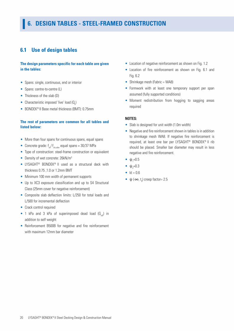
6.1 Use of design tables
The design parameters specific for each table are given in the tables:
• Spans: single, continuous, end or interior
• Spans: centre-to-centre (L)
• Thickness of the slab (D)
• Characteristic imposed 'live' load (Qk)
• BONDEK® II Base metal thickness (BMT): 0.75mm
The rest of parameters are common for all tables and listed below:
• More than four spans for continuous spans, equal spans
• Concrete grade: fck/ fck,cube equal spans = 30/37 MPa
• Type of construction: steel-frame construction or equivalent
• Density of wet concrete: 26kN/m3
• LYSAGHT® BONDEK® ll used as a structural deck with
thickness 0.75 ,1.0 or 1.2mm BMT
• Minimum 100 mm width of permanent supports
• Up to XC3 exposure classification and up to S4 Structural
Class (25mm cover for negative reinforcement)
• Composite slab deflection limits: L/250 for total loads and
L/500 for incremental deflection
• Crack control required
• 1 kPa and 3 kPa of superimposed dead load (Gsdl) in
addition to self weight
• Reinforcement B500B for negative and fire reinforcement
with maximum 12mm bar diameter
• Location of negative reinforcement as shown on Fig. 1.2
• Location of fire reinforcement as shown on Fig. 6.1 and
Fig. 6.2
• Shrinkage mesh (Fabric = WA8)
• Formwork with at least one temporary support per span
assumed (fully supported conditions)
• Moment redistribution from hogging to sagging areas
required
NOTES:
• Slab is designed for unit width (1.0m width)
• Negative and fire reinforcement shown in tables is in addition to shrinkage mesh WA8. If negative fire reinforcement is required, at least one bar per LYSAGHT® BONDEK® ll rib should be placed. Smaller bar diameter may result in less negative and fire reinforcement.
• ψ1=0.5
• ψ2=0.3
• kt = 0.6
• ψ ( , t0) creep factor= 2.5

21 LYSAGHT® BONDEK® II Steel Decking Design & Construction Manual
BONDEK®ll
Ln Ln
Restraint atend supportby mass of wall
Depth ofcompositeslab (D)
Continuous overinterior support
Top negative reinforcement
0.3Ln 0.3Ln 0.3Ln
Ls(span)
Concrete slab
L1 (span)
Steel beam
Additional fire reinforcementTop location for Interior Spansand bottom location for End Spans
Mesh
Note: 1/3 top negative reinforcement shall continue all over the span if ratio of live load to total dead load is more than 2.
Wal
lW
all
Figure 6.2LYSAGHT® BONDEK® ll continuous spans.
1440 50 570
Fire reinforcement required for fire
resistance of 120 minutes (mm2/m)
Top tensile (negative) reinforcements over supports (mm2/m)
Fire reinforcement required for fire resistance of 90 minutes (mm2/m)
BONDEK®ll
Ln
Restraint at end support by mass of wall
Depth ofcompositeslab (D)
0.3Ln
Concrete slab
L (span)
Steel beam
Additional fire reinforcementwill be provided at the samelevel as the mesh, bottom location
Mesh
Wal
lW
all
Figure 6.1LYSAGHT® BONDEK® ll for single spans.
NOTES:
1. Areas without cells mean that a design solution is not possible based on input parameters and design options presented in this manual. Contact your local BlueScope
Lysaght Technical Sales Representative for further options.
2. Single spans do not require top tensile reinforcement, relevant cells are not shown.
3. All spans are centre-to-centre.
4. A dash (-) means no fire reinforcement is necessary.
5. N/A means a design solution with this particular fire rating is not possible.
6. Top tensile/negative reinforcement is additional to
shrinkage mesh area
7. Nominal continuity reinforcement for single spans should be designed according to SS EN 1994-1-1:2009 Section 9.8.1 (2) or by using BONDEK® ll design software
6.2 Interpretation of table solutions
50 570
Fire reinforcement required for fire resistance of 120 minutes (mm2/m)
Bottom reinforcement required for fire resistance of 90 minutes (mm2/m)
KEY - SINGLE SPANS
KEY - CONTINUOUS SPANS
22 LYSAGHT® BONDEK® II Steel Decking Design & Construction Manual
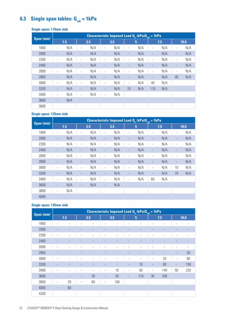
6.3 Single span tables: Gsdl
= 1kPa
Span (mm)Characteristic Imposed Load Qk (kPa)Gsdl = 1kPa
1.5 2.5 3.5 5 7.5 10.0
1800 - N/A - N/A - N/A - N/A - N/A - N/A
2000 - N/A - N/A - N/A - N/A - N/A - N/A
2200 - N/A - N/A - N/A - N/A - N/A - N/A
2400 - N/A - N/A - N/A - N/A - N/A - N/A
2600 - N/A - N/A - N/A - N/A - N/A - N/A
2800 - N/A - N/A - N/A - N/A - N/A 40 N/A
3000 - N/A - N/A - N/A - N/A 40 N/A
3200 - N/A - N/A - N/A 10 N/A 110 N/A
3400 - N/A - N/A - N/A
3600 - N/A
3800
Single spans 110mm slab
Span (mm)Characteristic Imposed Load Qk (kPa)Gsdl = 1kPa
1.5 2.5 3.5 5 7.5 10.0
1800 - N/A - N/A - N/A - N/A - N/A - N/A
2000 - N/A - N/A - N/A - N/A - N/A - N/A
2200 - N/A - N/A - N/A - N/A - N/A - N/A
2400 - N/A - N/A - N/A - N/A - N/A - N/A
2600 - N/A - N/A - N/A - N/A - N/A - N/A
2800 - N/A - N/A - N/A - N/A - N/A - N/A
3000 - N/A - N/A - N/A - N/A - N/A 10 N/A
3200 - N/A - N/A - N/A - N/A - N/A 70 N/A
3400 - N/A - N/A - N/A - N/A 60 N/A
3600 - N/A - N/A - N/A
3800 - N/A
4000
Single spans 120mm slab
Span (mm)Characteristic Imposed Load Qk (kPa)Gsdl = 1kPa
1.5 2.5 3.5 5 7.5 10.0
1800 - - - - - - - - - - - -
2000 - - - - - - - - - - - -
2200 - - - - - - - - - - - -
2400 - - - - - - - - - - - -
2600 - - - - - - - - - - - -
2800 - - - - - - - - - - - 20
3000 - - - - - - - - - 20 - 80
3200 - - - - - - - 10 - 80 - 150
3400 - - - - - 10 - 50 - 140 50 220
3600 - - - 20 - 50 - 110 30 200
3800 - 20 - 60 - 100
4000 - 60
4200
Single spans 130mm slab

23 LYSAGHT® BONDEK® II Steel Decking Design & Construction Manual
Single spans 150mm slab
Span (mm)Characteristic Imposed Load Qk (kPa)Gsdl = 1kPa
1.5 2.5 3.5 5 7.5 10.0
1800 - - - - - - - - - - - -
2000 - - - - - - - - - - - -
2200 - - - - - - - - - - - -
2400 - - - - - - - - - - - -
2600 - - - - - - - - - - - -
2800 - - - - - - - - - - - -
3000 - - - - - - - - - - - -
3200 - - - - - - - - - - - 30
3400 - - - - - - - - - 30 - 90
3600 - - - - - - - 10 - 80 - 140
3800 - - - - - 10 - 50 - 130 30 200
4000 - - - 20 - 50 - 100 20 180
4200 - 20 - 60 - 90
4400 - 60
4600
Single spans 175mm slab
Span (mm)Characteristic Imposed Load Qk (kPa)Gsdl = 1kPa
1.5 2.5 3.5 5 7.5 10.0
1800 - - - - - - - - - - - -
2000 - - - - - - - - - - - -
2200 - - - - - - - - - - - -
2400 - - - - - - - - - - - -
2600 - - - - - - - - - - - -
2800 - - - - - - - - - - - -
3000 - - - - - - - - - - - -
3200 - - - - - - - - - - - -
3400 - - - - - - - - - - - -
3600 - - - - - - - - - - - 40
3800 - - - - - - - - - 30 - 90
4000 - - - - - - - 20 - 80 - 140
4200 - - - - - 10 - 50 - 120 20 190
4400 - - - 20 - 50 - 100 10 170
4600 - 30 - 60 - 90 - 140
4800 - 60 - 100
5000

24 LYSAGHT® BONDEK® II Steel Decking Design & Construction Manual
Single spans 200mm slab
Single spans 250mm slab
Span (mm)Characteristic Imposed Load Qk (kPa)Gsdl = 1kPa
1.5 2.5 3.5 5 7.5 10.0
2000 - - - - - - - - - - - -
2200 - - - - - - - - - - - -
2400 - - - - - - - - - - - -
2600 - - - - - - - - - - - -
2800 - - - - - - - - - - - -
3000 - - - - - - - - - - - -
3200 - - - - - - - - - - - -
3400 - - - - - - - - - - - -
3600 - - - - - - - - - - - -
3800 - - - - - - - - - - - 20
4000 - - - - - - - - - 10 - 60
4200 - - - - - - - - - 50 - 110
4400 - - - - - - - 40 - 90 - 150
4600 - - - 10 - 30 - 70 - 140 30 200
4800 - 10 - 40 - 70 - 110 20 180 80 260
5000 - 40 - 80 - 110 - 150
5200 - 80 - 110 - 150
5400 - 110
5600
Span (mm)Characteristic Imposed Load Qk (kPa)Gsdl = 1kPa
1.5 2.5 3.5 5 7.5 10.0
2000 - - - - - - - - - - - -
2200 - - - - - - - - - - - -
2400 - - - - - - - - - - - -
2600 - - - - - - - - - - - -
2800 - - - - - - - - - - - -
3000 - - - - - - - - - - - -
3200 - - - - - - - - - - - -
3400 - - - - - - - - - - - -
3600 - - - - - - - - - - - -
3800 - - - - - - - - - - - -
4000 - - - - - - - - - - - -
4200 - - - - - - - - - - - 10
4400 - - - - - - - - - 10 - 50
4600 - - - - - - - - - 40 - 90
4800 - - - - - - - 30 - 80 - 130
5000 - - - 10 - 30 - 60 - 120 10 170
5200 - 10 - 40 - 60 - 100 - 160 40 220
5400 - 40 - 70 - 90 - 130 30 200 80 260
5600 - 70 - 100 - 130 10 170 60 240 120 310
5800 - 110 - 130 - 160 40 210 100 280
6000 - 140 10 170 30 200 70 250
6000

25 LYSAGHT® BONDEK® II Steel Decking Design & Construction Manual
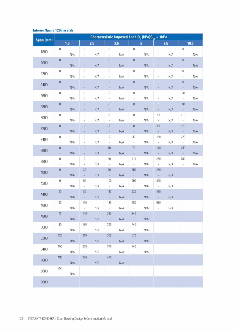
6.4 Interior span tables: Gsdl = 1kPa
Interior Spans 110mm slab
Span (mm)Characteristic Imposed Load Qk (kPa)Gsdl = 1kPa
1.5 2.5 3.5 5 7.5 10.0
18000 0 0 0 0 0
- N/A - N/A - N/A - N/A - N/A - N/A
20000 0 0 0 0 0
- N/A - N/A - N/A - N/A - N/A - N/A
22000 0 0 0 0 0
- N/A - N/A - N/A - N/A - N/A - N/A
24000 0 0 0 0 10
- N/A - N/A - N/A - N/A - N/A - N/A
26000 0 0 0 0 50
- N/A - N/A - N/A - N/A - N/A - N/A
28000 0 0 0 30 100
- N/A - N/A - N/A - N/A - N/A - N/A
30000 0 0 0 80 160
- N/A - N/A - N/A - N/A - N/A - N/A
32000 0 0 30 120 220
- N/A - N/A - N/A - N/A - N/A - N/A
34000 0 0 70 170 300
- N/A - N/A - N/A - N/A - N/A - N/A
36000 0 40 110 230
- N/A - N/A - N/A - N/A - N/A
38000 20 70 150 300
- N/A - N/A - N/A - N/A - N/A
40000 50 100 190 430
- N/A - N/A - N/A - N/A - N/A
420010 80 140 240 620
- N/A - N/A - N/A - N/A - N/A
440040 110 180 320
- N/A - N/A - N/A - N/A
460070 140 220 430
- N/A - N/A - N/A - N/A
4800100 180 280 590
- N/A - N/A - N/A - N/A
5000130 220 360
- N/A - N/A - N/A
5200160 260 480
- N/A - N/A - N/A
5400190 750
- N/A - N/A
5600
26 LYSAGHT® BONDEK® II Steel Decking Design & Construction Manual
Interior Spans 120mm slab
Span (mm)Characteristic Imposed Load Qk (kPa)Gsdl = 1kPa
1.5 2.5 3.5 5 7.5 10.0
18000 0 0 0 0 0
- N/A - N/A - N/A - N/A - N/A - N/A
20000 0 0 0 0 0
- N/A - N/A - N/A - N/A - N/A - N/A
22000 0 0 0 0 0
- N/A - N/A - N/A - N/A - N/A - N/A
24000 0 0 0 0 0
- N/A - N/A - N/A - N/A - N/A - N/A
26000 0 0 0 0 20
- N/A - N/A - N/A - N/A - N/A - N/A
28000 0 0 0 0 70
- N/A - N/A - N/A - N/A - N/A - N/A
30000 0 0 0 40 110
- N/A - N/A - N/A - N/A - N/A - N/A
32000 0 0 0 80 170
- N/A - N/A - N/A - N/A - N/A - N/A
34000 0 0 30 130 220
- N/A - N/A - N/A - N/A - N/A - N/A
36000 0 10 70 170 280
- N/A - N/A - N/A - N/A - N/A - N/A
38000 0 40 110 230 360
- N/A - N/A - N/A - N/A - N/A - N/A
40000 20 70 150 280
- N/A - N/A - N/A - N/A - N/A
42000 50 100 190 350
- N/A - N/A - N/A - N/A - N/A
440020 80 140 230 470
- N/A - N/A - N/A - N/A - N/A
460040 110 180 280 630
- N/A - N/A - N/A - N/A - N/A
480070 140 220 340
- N/A - N/A - N/A - N/A
500090 180 260 440
- N/A - N/A - N/A - N/A
5200120 210 300 570
- N/A - N/A - N/A - N/A
5400150 250 370 740
- N/A - N/A - N/A - N/A
5600190 290 470
- N/A - N/A - N/A
5800250
- N/A
6000
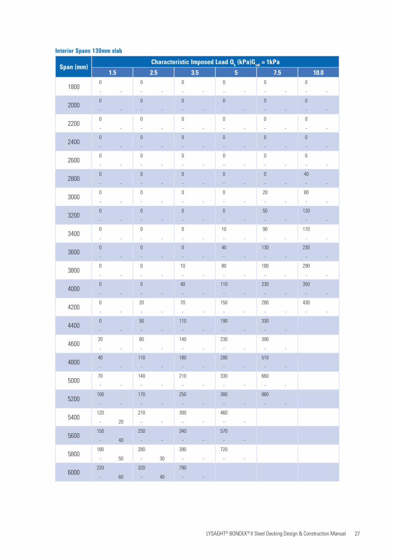
27 LYSAGHT® BONDEK® II Steel Decking Design & Construction Manual
Interior Spans 130mm slab
Span (mm)Characteristic Imposed Load Qk (kPa)Gsdl = 1kPa
1.5 2.5 3.5 5 7.5 10.0
18000 0 0 0 0 0
- - - - - - - - - - - -
20000 0 0 0 0 0
- - - - - - - - - - - -
22000 0 0 0 0 0
- - - - - - - - - - - -
24000 0 0 0 0 0
- - - - - - - - - - - -
26000 0 0 0 0 0
- - - - - - - - - - - -
28000 0 0 0 0 40
- - - - - - - - - - - -
30000 0 0 0 20 80
- - - - - - - - - - - -
32000 0 0 0 50 120
- - - - - - - - - - - -
34000 0 0 10 90 170
- - - - - - - - - - - -
36000 0 0 40 130 230
- - - - - - - - - - - -
38000 0 10 80 180 290
- - - - - - - - - - - -
40000 0 40 110 230 350
- - - - - - - - - - - -
42000 20 70 150 280 430
- - - - - - - - - - - -
44000 50 110 190 330
- - - - - - - - - -
460020 80 140 230 390
- - - - - - - - - -
480040 110 180 280 510
- - - - - - - - - -
500070 140 210 330 660
- - - - - - - - - -
5200100 170 250 380 860
- - - - - - - - - -
5400120 210 300 460
- 20 - - - - - -
5600150 250 340 570
- 40 - - - - - -
5800180 280 390 720
- 50 - 30 - - - -
6000220 320 790
- 60 - 40 - -
28 LYSAGHT® BONDEK® II Steel Decking Design & Construction Manual
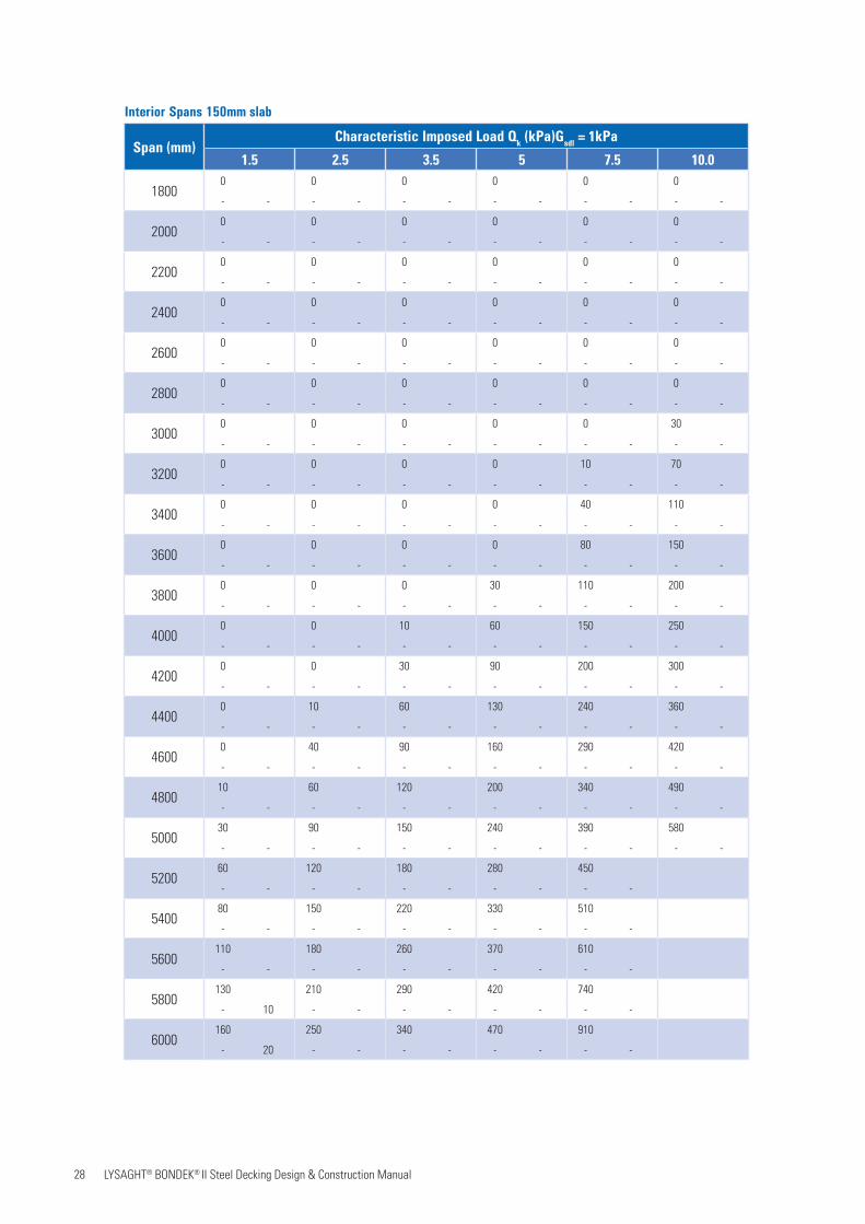
Interior Spans 150mm slab
Span (mm)Characteristic Imposed Load Qk (kPa)Gsdl = 1kPa
1.5 2.5 3.5 5 7.5 10.0
18000 0 0 0 0 0
- - - - - - - - - - - -
20000 0 0 0 0 0
- - - - - - - - - - - -
22000 0 0 0 0 0
- - - - - - - - - - - -
24000 0 0 0 0 0
- - - - - - - - - - - -
26000 0 0 0 0 0
- - - - - - - - - - - -
28000 0 0 0 0 0
- - - - - - - - - - - -
30000 0 0 0 0 30
- - - - - - - - - - - -
32000 0 0 0 10 70
- - - - - - - - - - - -
34000 0 0 0 40 110
- - - - - - - - - - - -
36000 0 0 0 80 150
- - - - - - - - - - - -
38000 0 0 30 110 200
- - - - - - - - - - - -
40000 0 10 60 150 250
- - - - - - - - - - - -
42000 0 30 90 200 300
- - - - - - - - - - - -
44000 10 60 130 240 360
- - - - - - - - - - - -
46000 40 90 160 290 420
- - - - - - - - - - - -
480010 60 120 200 340 490
- - - - - - - - - - - -
500030 90 150 240 390 580
- - - - - - - - - - - -
520060 120 180 280 450
- - - - - - - - - -
540080 150 220 330 510
- - - - - - - - - -
5600110 180 260 370 610
- - - - - - - - - -
5800130 210 290 420 740
- 10 - - - - - - - -
6000160 250 340 470 910
- 20 - - - - - - - -

29 LYSAGHT® BONDEK® II Steel Decking Design & Construction Manual
Interior Spans 175mm slab
Span (mm)Characteristic Imposed Load Qk (kPa)Gsdl = 1kPa
1.5 2.5 3.5 5 7.5 10.0
20000 0 0 0 0 0
- - - - - - - - - - - -
22000 0 0 0 0 0
- - - - - - - - - - - -
24000 0 0 0 0 0
- - - - - - - - - - - -
26000 0 0 0 0 0
- - - - - - - - - - - -
28000 0 0 0 0 0
- - - - - - - - - - - -
30000 0 0 0 0 0
- - - - - - - - - - - -
32000 0 0 0 0 20
- - - - - - - - - - - -
34000 0 0 0 0 50
- - - - - - - - - - - -
36000 0 0 0 30 90
- - - - - - - - - - - -
38000 0 0 0 60 130
- - - - - - - - - - - -
40000 0 0 20 90 170
- - - - - - - - - - - -
42000 0 0 50 130 210
- - - - - - - - - - - -
44000 0 20 70 170 260
- - - - - - - - - - - -
46000 10 40 100 210 310
- - - - - - - - - - - -
48000 30 70 140 250 360
- - - - - - - - - - - -
50000 50 100 170 290 420
- - - - - - - - - - - -
520030 80 130 210 340 480
- - - - - - - - - - - -
540050 100 160 240 390 540
- - - - - - - - - - - -
560070 130 190 280 440 600
- - - - - - - - - - - -
580090 160 220 320 490 670
- - - - - - - - - - - -
6000120 190 260 360 550
- - - - - - - - - -
30 LYSAGHT® BONDEK® II Steel Decking Design & Construction Manual
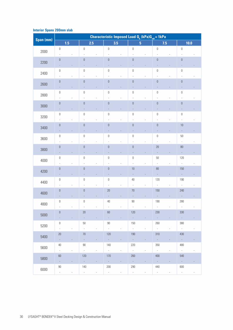
Interior Spans 200mm slab
Span (mm)Characteristic Imposed Load Qk (kPa)Gsdl = 1kPa
1.5 2.5 3.5 5 7.5 10.0
20000 0 0 0 0 0
- - - - - - - - - - - -
22000 0 0 0 0 0
- - - - - - - - - - - -
24000 0 0 0 0 0
- - - - - - - - - - - -
26000 0 0 0 0 0
- - - - - - - - - - - -
28000 0 0 0 0 0
- - - - - - - - - - - -
30000 0 0 0 0 0
- - - - - - - - - - - -
32000 0 0 0 0 0
- - - - - - - - - - - -
34000 0 0 0 0 10
- - - - - - - - - - - -
36000 0 0 0 0 50
- - - - - - - - - - - -
38000 0 0 0 20 80
- - - - - - - - - - - -
40000 0 0 0 50 120
- - - - - - - - - - - -
42000 0 0 10 80 150
- - - - - - - - - - - -
44000 0 0 40 120 190
- - - - - - - - - - - -
46000 0 20 70 150 240
- - - - - - - - - - - -
48000 0 40 90 190 280
- - - - - - - - - - - -
50000 20 60 120 230 330
- - - - - - - - - - - -
52000 50 90 150 260 380
- - - - - - - - - - - -
540020 70 120 190 310 430
- - - - - - - - - - - -
560040 90 140 220 350 480
- - - - - - - - - - - -
580060 120 170 260 400 540
- - - - - - - - - - - -
600090 140 200 290 440 600
- - - - - - - - - - - -

31 LYSAGHT® BONDEK® II Steel Decking Design & Construction Manual
Interior Spans 250mm slab
Span (mm)Characteristic Imposed Load Qk (kPa)Gsdl = 1kPa
1.5 2.5 3.5 5 7.5 10.0
20000 0 0 0 0 0
- - - - - - - - - - - -
22000 0 0 0 0 0
- - - - - - - - - - - -
24000 0 0 0 0 0
- - - - - - - - - - - -
26000 0 0 0 0 0
- - - - - - - - - - - -
28000 0 0 0 0 0
- - - - - - - - - - - -
30000 0 0 0 0 0
- - - - - - - - - - - -
32000 0 0 0 0 0
- - - - - - - - - - - -
34000 0 0 0 0 0
- - - - - - - - - - - -
36000 0 0 0 0 0
- - - - - - - - - - - -
38000 0 0 0 0 20
- - - - - - - - - - - -
40000 0 0 0 0 50
- - - - - - - - - - - -
42000 0 0 0 30 80
- - - - - - - - - - - -
44000 0 0 0 50 110
- - - - - - - - - - - -
46000 0 0 20 80 140
- - - - - - - - - - - -
48000 0 0 40 110 180
- - - - - - - - - - - -
50000 0 20 60 140 220
- - - - - - - - - - - -
52000 10 40 90 170 260
- - - - - - - - - - - -
54000 30 60 120 210 300
- - - - - - - - - - - -
560010 50 90 140 240 340
- - - - - - - - - - - -
580030 70 110 170 280 380
- - - - - - - - - - - -
600050 90 140 200 310 430
- - - - - - - - - - - -
32 LYSAGHT® BONDEK® II Steel Decking Design & Construction Manual
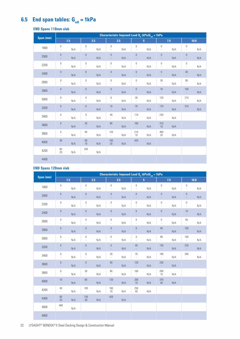
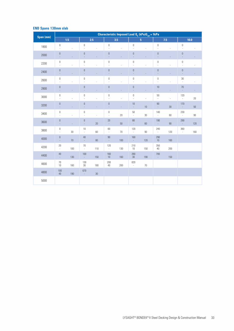
6.5 End span tables: Gsdl = 1kPa
END Spans 110mm slab
Span (mm)Characteristic Imposed Load Qk (kPa)Gsdl = 1kPa
1.5 2.5 3.5 5 7.5 10.0
1800 0- N/A
0- N/A
0- N/A
0- N/A
0- N/A
0- N/A
2000 0- N/A
0- N/A
0- N/A
0- N/A
0- N/A
0- N/A
2200 0- N/A
0- N/A
0- N/A
0- N/A
0- N/A
0- N/A
2400 0- N/A
0- N/A
0- N/A
0- N/A
0- N/A
40- N/A
2600 0- N/A
0- N/A
0- N/A
0- N/A
30- N/A
90- N/A
2800 0- N/A
0- N/A
0- N/A
0- N/A
70- N/A
150- N/A
3000 0- N/A
0- N/A
0- N/A
30- N/A
120- N/A
210- N/A
3200 0- N/A
0- N/A
10- N/A
70- N/A
170- N/A
310- N/A
3400 0- N/A
0- N/A
40- N/A
110- N/A
230- N/A
3600 0- N/A
30- N/A
80- N/A
160- N/A
31010 N/A
3800 0- N/A
60- N/A
120- N/A
21010 N/A
46020 N/A
4000 30- N/A
9010 N/A
16020 N/A
420- N/A
4200 6020 N/A
330- N/A
4400
END Spans 120mm slab
Span (mm)Characteristic Imposed Load Qk (kPa)Gsdl = 1kPa
1.5 2.5 3.5 5 7.5 10.0
1800 0- N/A
0- N/A
0- N/A
0- N/A
0- N/A
0- N/A
2000 0- N/A
0- N/A
0- N/A
0- N/A
0- N/A
0- N/A
2200 0- N/A
0- N/A
0- N/A
0- N/A
0- N/A
0- N/A
2400 0- N/A
0- N/A
0- N/A
0- N/A
0- N/A
10- N/A
2600 0- N/A
0- N/A
0- N/A
0- N/A
0- N/A
50- N/A
2800 0- N/A
0- N/A
0- N/A
0- N/A
40- N/A
100- N/A
3000 0- N/A
0- N/A
0- N/A
0- N/A
80- N/A
160- N/A
3200 0- N/A
0- N/A
0- N/A
40- N/A
130- N/A
220- N/A
3400 0- N/A
0- N/A
20- N/A
70- N/A
180- N/A
280- N/A
3600 0- N/A
0- N/A
50- N/A
120- N/A
230- N/A
3800 0- N/A
30- N/A
80- N/A
160- N/A
29010 N/A
4000 10- N/A
60- N/A
120- N/A
20010 N/A
37040 N/A
4200 40- N/A
100- N/A
16010 N/A
25040 N/A
4400 6020 N/A
13030 N/A
420- N/A
4600 480- N/A
4800
33 LYSAGHT® BONDEK® II Steel Decking Design & Construction Manual
END Spans 130mm slab
Span (mm)Characteristic Imposed Load Qk (kPa)Gsdl = 1kPa
1.5 2.5 3.5 5 7.5 10.0
1800 0- -
0- -
0- -
0- -
0- -
0- -
2000 0- -
0- -
0- -
0- -
0- -
0- -
2200 0- -
0- -
0- -
0- -
0- -
0- -
2400 0- -
0- -
0- -
0- -
0- -
0- -
2600 0- -
0- -
0- -
0- -
0- -
30- -
2800 0- -
0- -
0- -
0- -
10- -
70- -
3000 0- -
0- -
0- -
0- -
50- -
120- 20
3200 0- -
0- -
0- -
10- 10
90- 30
170- 50
3400 0- -
0- -
0- 20
50- 30
140- 60
230- 90
3600 0- -
0- 20
20- 50
80- 60
190- 90
290- 120
3800 0- 30
10- 60
60- 70
120- 90
240- 120
360- 160
4000 0- 70
40- 80
90- 100
160- 120
29010 160
4200 20- 100
70- 110
120- 130
21010 150
35040 200
4400 40- 130
100- 150
16010 160
26030 190
700- 150
4600 7010 160
13030 180
20040 200
820- 70
4800 10040 190
670- 30
5000
34 LYSAGHT® BONDEK® II Steel Decking Design & Construction Manual
Span (mm)Characteristic Imposed Load Qk (kPa)Gsdl = 1kPa
1.5 2.5 3.5 5 7.5 10.0
1800 0- -
0- -
0- -
0- -
0- -
0- -
2000 0- -
0- -
0- -
0- -
0- -
0- -
2200 0- -
0- -
0- -
0- -
0- -
0- -
2400 0- -
0- -
0- -
0- -
0- -
0- -
2600 0- -
0- -
0- -
0- -
0- -
0- -
2800 0- -
0- -
0- -
0- -
0- -
20- -
3000 0- -
0- -
0- -
0- -
10- -
60- -
3200 0- -
0- -
0- -
0- -
40- -
110- 10
3400 0- -
0- -
0- -
10- -
80- 20
150- 30
3600 0- -
0- -
0- -
40- 20
120- 40
200- 60
3800 0- -
0- 10
20- 30
70- 40
160- 70
260- 90
4000 0- 20
10- 40
50- 50
110- 60
210- 90
310- 120
4200 0- 50
30- 70
80- 70
140- 90
260- 120
38010 150
4400 10- 80
60- 90
110- 100
180- 120
31010 150
44040 180
4600 30- 100
90- 110
140- 130
22010 150
36040 180
4800 60- 130
12010 140
18020 150
27030 180
42060 220
5000 9020 150
15030 170
21040 190
31060 210
1320- 100
5200 11050 180
18060 200
480- 120
1380- 70
5400 510- 60
1160- 30
5600
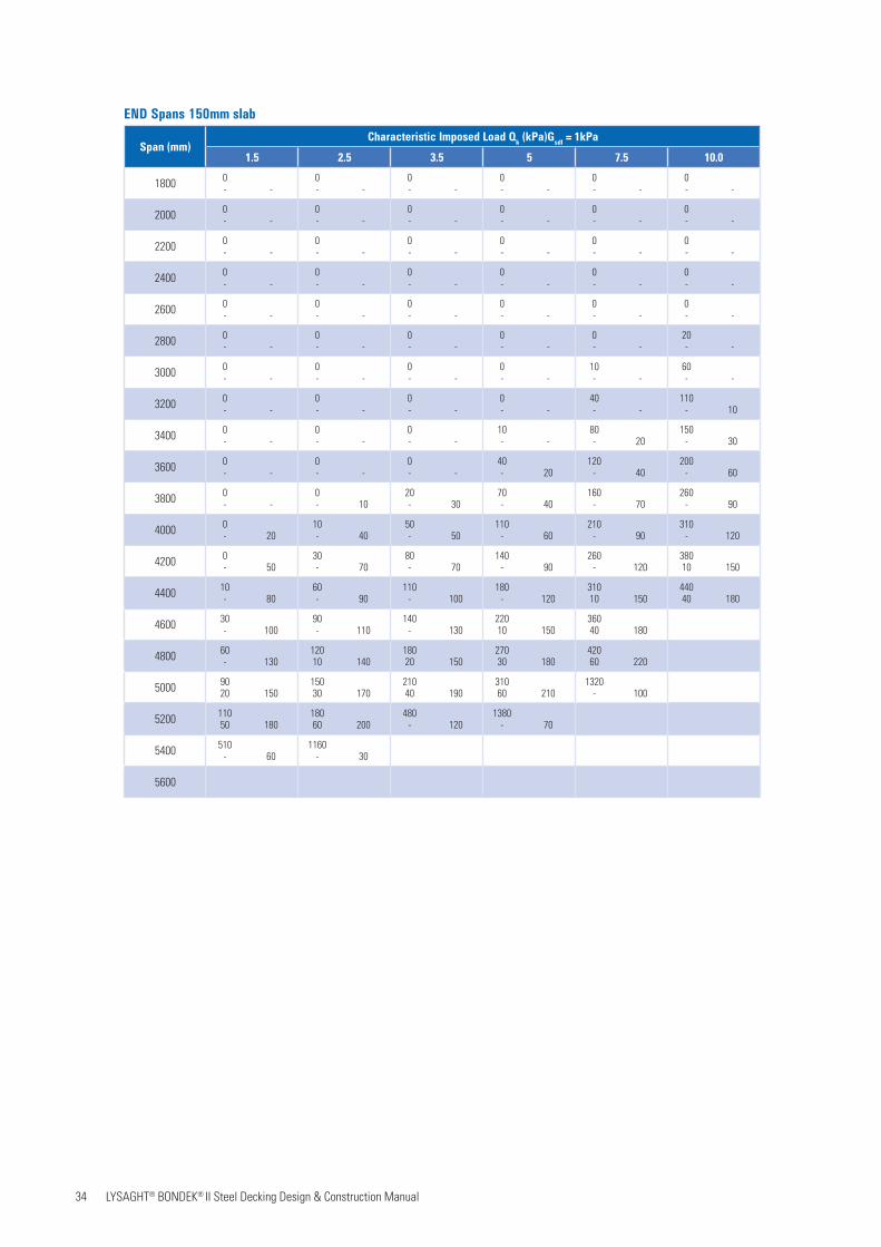
END Spans 150mm slab
35 LYSAGHT® BONDEK® II Steel Decking Design & Construction Manual
Span (mm)Characteristic Imposed Load Qk (kPa)Gsdl = 1kPa
1.5 2.5 3.5 5 7.5 10.0
2000 0- -
0- -
0- -
0- -
0- -
0- -
2200 0- -
0- -
0- -
0- -
0- -
0- -
2400 0- -
0- -
0- -
0- -
0- -
0- -
2600 0- -
0- -
0- -
0- -
0- -
0- -
2800 0- -
0- -
0- -
0- -
0- -
0- -
3000 0- -
0- -
0- -
0- -
0- -
20- -
3200 0- -
0- -
0- -
0- -
0- -
50- -
3400 0- -
0- -
0- -
0- -
30- -
90- -
3600 0- -
0- -
0- -
0- -
70- -
130- 20
3800 0- -
0- -
0- -
30- 10
100- 30
180- 40
4000 0- -
0- -
10- 20
60- 30
140- 50
220- 70
4200 0- 10
0- 30
40- 40
90- 50
180- 70
280- 90
4400 0- 40
20- 50
60- 60
120- 70
220- 90
330- 110
4600 10- 60
50- 70
90- 80
160- 90
270- 120
39010 140
4800 30- 90
80- 90
120- 110
200- 120
32020 140
44040 170
5000 50- 110
100- 120
16010 120
23020 140
37040 170
51060 200
5200 8010 130
13020 140
19030 150
28040 170
42060 200
57090 240
5400 10030 150
16040 170
22050 180
32060 200
48080 230
5600 13050 180
19060 190
26070 200
36080 230
1130- 120
5800 16070 200
23080 220
40050 190
1140- 90
6000 430- 130
970- 60
1600- 80
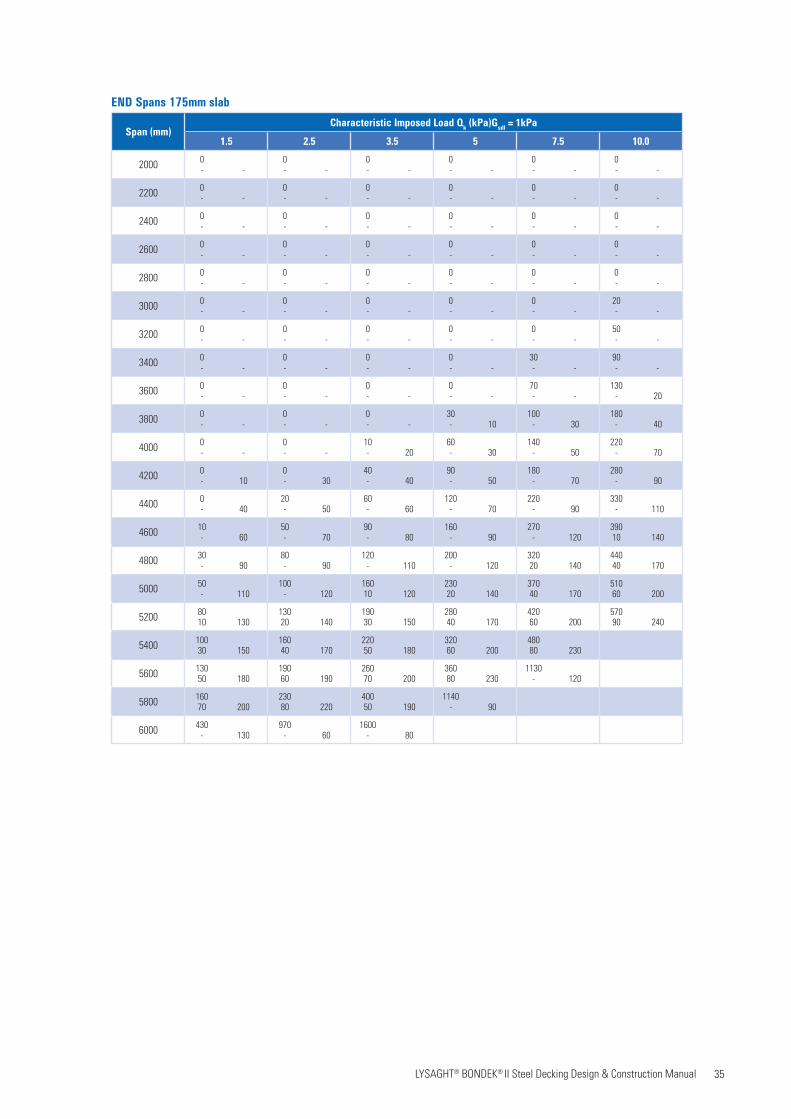
END Spans 175mm slab

36 LYSAGHT® BONDEK® II Steel Decking Design & Construction Manual
Span (mm)Characteristic Imposed Load Qk (kPa)Gsdl = 1kPa
1.5 2.5 3.5 5 7.5 10.0
2000 0- -
0- -
0- -
0- -
0- -
0- -
2200 0- -
0- -
0- -
0- -
0- -
0- -
2400 0- -
0- -
0- -
0- -
0- -
0- -
2600 0- -
0- -
0- -
0- -
0- -
0- -
2800 0- -
0- -
0- -
0- -
0- -
0- -
3000 0- -
0- -
0- -
0- -
0- -
0- -
3200 0- -
0- -
0- -
0- -
0- -
20- -
3400 0- -
0- -
0- -
0- -
0- -
50- -
3600 0- -
0- -
0- -
0- -
30- -
90- -
3800 0- -
0- -
0- -
0- -
60- 10
120- 20
4000 0- -
0- -
0- -
30- 10
90- 20
160- 40
4200 0- -
0- -
10- 20
50- 30
130- 40
210- 50
4400 0- 10
0- 30
30- 40
80- 50
170- 60
250- 80
4600 0- 40
20- 50
60- 50
110- 70
210- 80
300- 100
4800 10- 60
50- 70
90- 70
150- 80
250- 100
35010 120
5000 30- 80
70- 90
110- 100
180- 110
29010 130
41020 150
5200 50- 100
100- 110
14010 120
22010 130
34030 150
46050 170
5400 7010 120
13010 130
18020 140
25030 150
39050 170
52070 200
5600 10030 140
15030 150
21040 160
29050 180
44070 200
58090 230
5800 12050 170
18050 180
24060 190
33070 200
49090 230
650110 260
6000 15060 190
21070 200
28080 210
38090 230
540110 260
105050 190
END Spans 200mm slab

37 LYSAGHT® BONDEK® II Steel Decking Design & Construction Manual
Span (mm)Characteristic Imposed Load Qk (kPa)Gsdl = 1kPa
1.5 2.5 3.5 5 7.5 10.0
2000 0- -
0- -
0- -
0- -
0- -
0- -
2200 0- -
0- -
0- -
0- -
0- -
0- -
2400 0- -
0- -
0- -
0- -
0- -
0- -
2600 0- -
0- -
0- -
0- -
0- -
0- -
2800 0- -
0- -
0- -
0- -
0- -
0- -
3000 0- -
0- -
0- -
0- -
0- -
0- -
3200 0- -
0- -
0- -
0- -
0- -
0- -
3400 0- -
0- -
0- -
0- -
0- -
0- -
3600 0- -
0- -
0- -
0- -
0- -
20- -
3800 0- -
0- -
0- -
0- -
10- -
60- -
4000 0- -
0- -
0- -
0- -
40- -
90- -
4200 0- -
0- -
0- -
10- -
60- 10
120- 20
4400 0- -
0- -
0- 10
30- 20
100- 20
160- 40
4600 0- -
0- 20
20- 30
60- 30
130- 40
200- 50
4800 0- 20
10- 40
40- 40
80- 50
160- 60
240- 70
5000 0- 50
30- 60
60- 60
110- 70
200- 80
280- 90
5200 20- 70
50- 70
90- 80
140- 90
230- 100
330- 110
5400 40- 80
80- 90
120- 90
170- 100
27010 12 0
37020 130
5600 60- 100
10010 110
14010 110
21010 120
31030 140
42040 160
5800 8020 120
13020 130
17030 130
24030 140
36040 160
47060 180
6000 11030 140
15040 150
20040 150
28050 160
40060 180
52080 200
END Spans 250mm slab
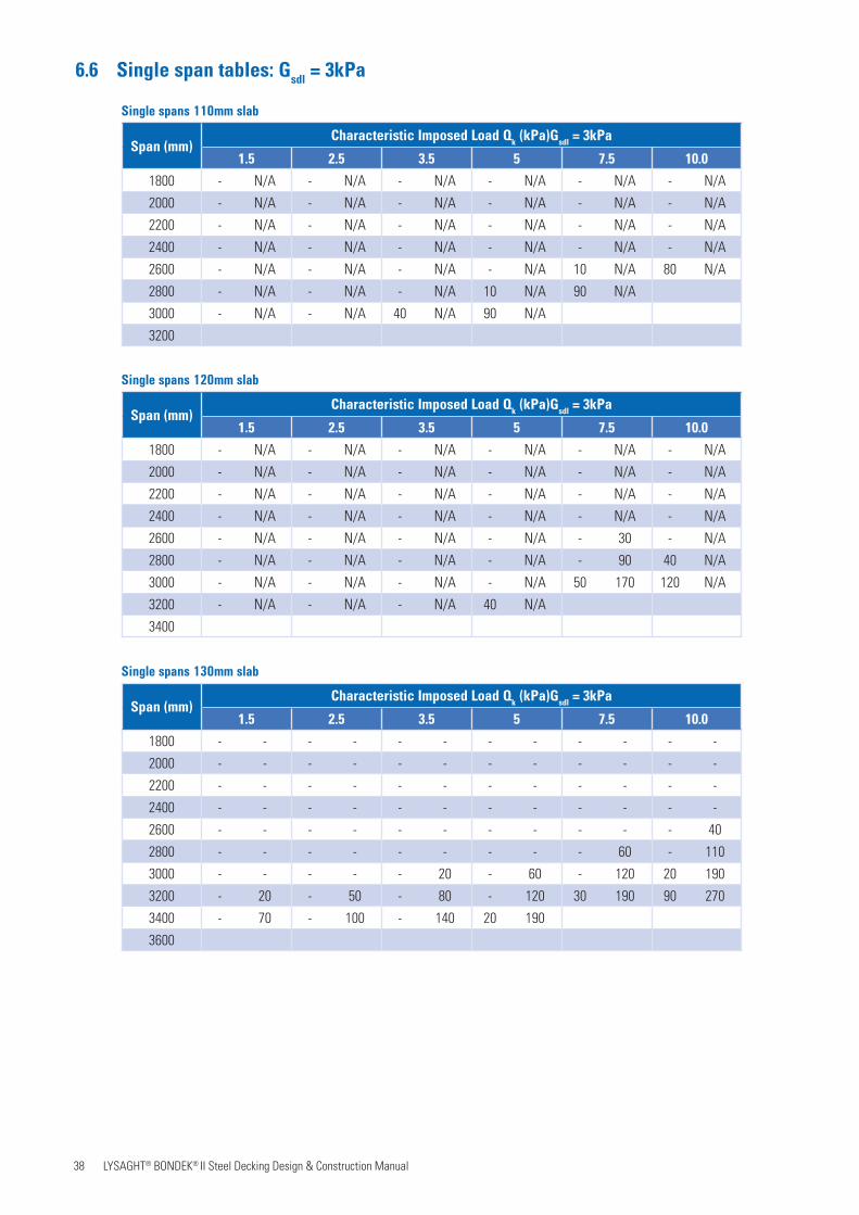
38 LYSAGHT® BONDEK® II Steel Decking Design & Construction Manual
6.6 Single span tables: Gsdl = 3kPa
Span (mm)Characteristic Imposed Load Qk (kPa)Gsdl = 3kPa
1.5 2.5 3.5 5 7.5 10.0
1800 - N/A - N/A - N/A - N/A - N/A - N/A
2000 - N/A - N/A - N/A - N/A - N/A - N/A
2200 - N/A - N/A - N/A - N/A - N/A - N/A
2400 - N/A - N/A - N/A - N/A - N/A - N/A
2600 - N/A - N/A - N/A - N/A 10 N/A 80 N/A
2800 - N/A - N/A - N/A 10 N/A 90 N/A
3000 - N/A - N/A 40 N/A 90 N/A
3200
Single spans 110mm slab
Span (mm)Characteristic Imposed Load Qk (kPa)Gsdl = 3kPa
1.5 2.5 3.5 5 7.5 10.0
1800 - N/A - N/A - N/A - N/A - N/A - N/A
2000 - N/A - N/A - N/A - N/A - N/A - N/A
2200 - N/A - N/A - N/A - N/A - N/A - N/A
2400 - N/A - N/A - N/A - N/A - N/A - N/A
2600 - N/A - N/A - N/A - N/A - 30 - N/A
2800 - N/A - N/A - N/A - N/A - 90 40 N/A
3000 - N/A - N/A - N/A - N/A 50 170 120 N/A
3200 - N/A - N/A - N/A 40 N/A
3400
Single spans 120mm slab
Single spans 130mm slab
Span (mm)Characteristic Imposed Load Qk (kPa)Gsdl = 3kPa
1.5 2.5 3.5 5 7.5 10.0
1800 - - - - - - - - - - - -
2000 - - - - - - - - - - - -
2200 - - - - - - - - - - - -
2400 - - - - - - - - - - - -
2600 - - - - - - - - - - - 40
2800 - - - - - - - - - 60 - 110
3000 - - - - - 20 - 60 - 120 20 190
3200 - 20 - 50 - 80 - 120 30 190 90 270
3400 - 70 - 100 - 140 20 190
3600
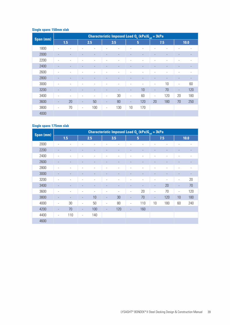
39 LYSAGHT® BONDEK® II Steel Decking Design & Construction Manual
Single spans 150mm slab
Span (mm)Characteristic Imposed Load Qk (kPa)Gsdl = 3kPa
1.5 2.5 3.5 5 7.5 10.0
1800 - - - - - - - - - - - -
2000 - - - - - - - - - - - -
2200 - - - - - - - - - - - -
2400 - - - - - - - - - - - -
2600 - - - - - - - - - - - -
2800 - - - - - - - - - - - -
3000 - - - - - - - - - 10 - 60
3200 - - - - - - - 10 - 70 - 120
3400 - - - - - 30 - 60 - 120 20 180
3600 - 20 - 50 - 80 - 120 20 180 70 250
3800 - 70 - 100 - 130 10 170
4000
Single spans 175mm slab
Span (mm)Characteristic Imposed Load Qk (kPa)Gsdl = 3kPa
1.5 2.5 3.5 5 7.5 10.0
2000 - - - - - - - - - - - -
2200 - - - - - - - - - - - -
2400 - - - - - - - - - - - -
2600 - - - - - - - - - - - -
2800 - - - - - - - - - - - -
3000 - - - - - - - - - - - -
3200 - - - - - - - - - - - 20
3400 - - - - - - - - - 20 - 70
3600 - - - - - - - 20 - 70 - 120
3800 - - - 10 - 30 - 70 - 120 10 180
4000 - 30 - 50 - 80 - 110 10 180 60 240
4200 - 70 - 100 - 120 - 160
4400 - 110 - 140
4600

40 LYSAGHT® BONDEK® II Steel Decking Design & Construction Manual
Single spans 200mm slab
Span (mm)Characteristic Imposed Load Qk (kPa)Gsdl = 3kPa
1.5 2.5 3.5 5 7.5 10.0
2000 - - - - - - - - - - - -
2200 - - - - - - - - - - - -
2400 - - - - - - - - - - - -
2600 - - - - - - - - - - - -
2800 - - - - - - - - - - - -
3000 - - - - - - - - - - - -
3200 - - - - - - - - - - - -
3400 - - - - - - - - - - - -
3600 - - - - - - - - - 10 - 50
3800 - - - - - - - - - 50 - 90
4000 - - - - - 10 - 40 - 90 - 140
4200 - 10 - 30 - 50 - 90 - 140 30 200
4400 - 50 - 70 - 90 - 130 20 190 70 250
4600 - 90 - 110 - 140 10 180 70 240
4800 - 130 - 150 20 180
5000
Single spans 250mm slab
Span (mm)Characteristic Imposed Load Qk (kPa)Gsdl = 3kPa
1.5 2.5 3.5 5 7.5 10.0
2000 - - - - - - - - - - - -
2200 - - - - - - - - - - - -
2400 - - - - - - - - - - - -
2600 - - - - - - - - - - - -
2800 - - - - - - - - - - - -
3000 - - - - - - - - - - - -
3200 - - - - - - - - - - - -
3400 - - - - - - - - - - - -
3600 - - - - - - - - - - - -
3800 - - - - - - - - - - - 30
4000 - - - - - - - - - - - 70
4200 - - - - - - - - - 40 - 120
4400 - - - - - 10 - 30 - 80 - 160
4600 - 10 - 20 - 40 - 70 - 120 40 210
4800 - 40 - 60 - 80 - 110 - 160 80 260
5000 - 70 - 90 - 120 - 150 30 200 120 310
5200 - 110 - 130 - 160 20 190 70 250
5400 - 140 10 170 30 200 60 240 110 300
5600 20 180 40 210 60 240 100 280
5800 50 220
6000
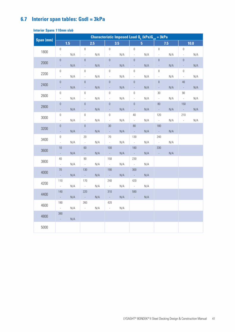
41 LYSAGHT® BONDEK® II Steel Decking Design & Construction Manual
6.7 Interior span tables: Gsdl = 3kPa
Interior Spans 110mm slab
Span (mm)Characteristic Imposed Load Qk (kPa)Gsdl = 3kPa
1.5 2.5 3.5 5 7.5 10.0
18000 0 0 0 0 0
- N/A - N/A - N/A - N/A - N/A - N/A
20000 0 0 0 0 0
- N/A - N/A - N/A - N/A - N/A - N/A
22000 0 0 0 0 0
- N/A - N/A - N/A - N/A - N/A - N/A
24000 0 0 0 0 40
- N/A - N/A - N/A - N/A - N/A - N/A
26000 0 0 0 30 90
- N/A - N/A - N/A - N/A - N/A - N/A
28000 0 0 0 80 150
- N/A - N/A - N/A - N/A - N/A - N/A
30000 0 0 40 120 210
- N/A - N/A - N/A - N/A - N/A - N/A
32000 0 30 80 180
- N/A - N/A - N/A - N/A - N/A
34000 20 70 130 240
- N/A - N/A - N/A - N/A - N/A
360010 60 100 180 330
- N/A - N/A - N/A - N/A - N/A
380040 90 150 230
- N/A - N/A - N/A - N/A
400070 130 190 300
- N/A - N/A - N/A - N/A
4200110 170 240 420
- N/A - N/A - N/A - N/A
4400140 220 310 590
- N/A - N/A - N/A - N/A
4600180 260 420
- N/A - N/A - N/A
4800380
- N/A
5000
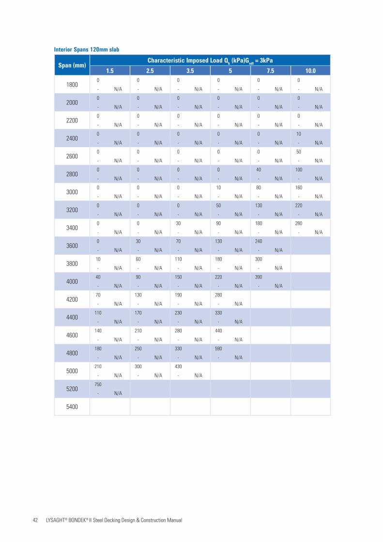
42 LYSAGHT® BONDEK® II Steel Decking Design & Construction Manual
Interior Spans 120mm slab
Span (mm)Characteristic Imposed Load Qk (kPa)Gsdl = 3kPa
1.5 2.5 3.5 5 7.5 10.0
18000 0 0 0 0 0
- N/A - N/A - N/A - N/A - N/A - N/A
20000 0 0 0 0 0
- N/A - N/A - N/A - N/A - N/A - N/A
22000 0 0 0 0 0
- N/A - N/A - N/A - N/A - N/A - N/A
24000 0 0 0 0 10
- N/A - N/A - N/A - N/A - N/A - N/A
26000 0 0 0 0 50
- N/A - N/A - N/A - N/A - N/A - N/A
28000 0 0 0 40 100
- N/A - N/A - N/A - N/A - N/A - N/A
30000 0 0 10 80 160
- N/A - N/A - N/A - N/A - N/A - N/A
32000 0 0 50 130 220
- N/A - N/A - N/A - N/A - N/A - N/A
34000 0 30 90 180 280
- N/A - N/A - N/A - N/A - N/A - N/A
36000 30 70 130 240
- N/A - N/A - N/A - N/A - N/A
380010 60 110 180 300
- N/A - N/A - N/A - N/A - N/A
400040 90 150 220 390
- N/A - N/A - N/A - N/A - N/A
420070 130 190 280
- N/A - N/A - N/A - N/A
4400110 170 230 330
- N/A - N/A - N/A - N/A
4600140 210 280 440
- N/A - N/A - N/A - N/A
4800180 250 330 590
- N/A - N/A - N/A - N/A
5000210 300 430
- N/A - N/A - N/A
5200750
- N/A
5400
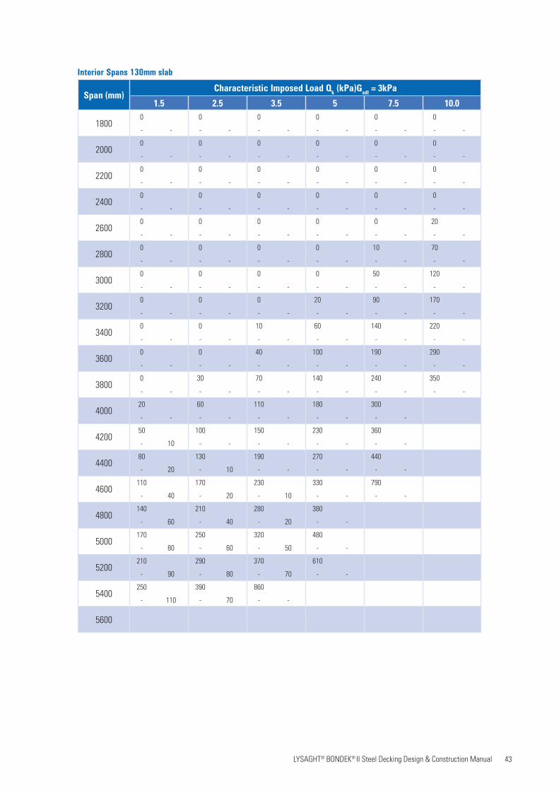
43 LYSAGHT® BONDEK® II Steel Decking Design & Construction Manual
Interior Spans 130mm slab
Span (mm)Characteristic Imposed Load Qk (kPa)Gsdl = 3kPa
1.5 2.5 3.5 5 7.5 10.0
18000 0 0 0 0 0
- - - - - - - - - - - -
20000 0 0 0 0 0
- - - - - - - - - - - -
22000 0 0 0 0 0
- - - - - - - - - - - -
24000 0 0 0 0 0
- - - - - - - - - - - -
26000 0 0 0 0 20
- - - - - - - - - - - -
28000 0 0 0 10 70
- - - - - - - - - - - -
30000 0 0 0 50 120
- - - - - - - - - - - -
32000 0 0 20 90 170
- - - - - - - - - - - -
34000 0 10 60 140 220
- - - - - - - - - - - -
36000 0 40 100 190 290
- - - - - - - - - - - -
38000 30 70 140 240 350
- - - - - - - - - - - -
400020 60 110 180 300
- - - - - - - - - -
420050 100 150 230 360
- 10 - - - - - - - -
440080 130 190 270 440
- 20 - 10 - - - - - -
4600110 170 230 330 790
- 40 - 20 - 10 - - - -
4800140 210 280 380
- 60 - 40 - 20 - -
5000170 250 320 480
- 80 - 60 - 50 - -
5200210 290 370 610
- 90 - 80 - 70 - -
5400250 390 860
- 110 - 70 - -
5600
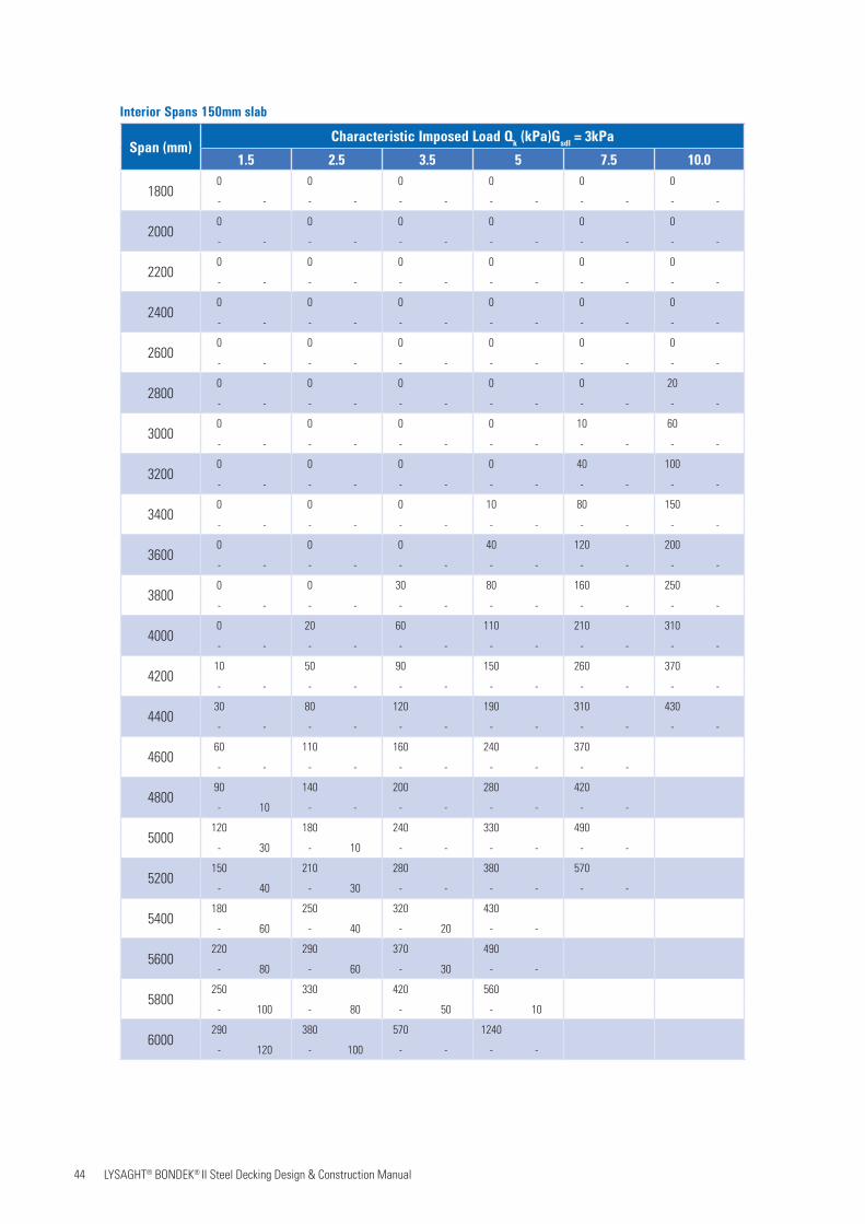
44 LYSAGHT® BONDEK® II Steel Decking Design & Construction Manual
Interior Spans 150mm slab
Span (mm)Characteristic Imposed Load Qk (kPa)Gsdl = 3kPa
1.5 2.5 3.5 5 7.5 10.0
18000 0 0 0 0 0
- - - - - - - - - - - -
20000 0 0 0 0 0
- - - - - - - - - - - -
22000 0 0 0 0 0
- - - - - - - - - - - -
24000 0 0 0 0 0
- - - - - - - - - - - -
26000 0 0 0 0 0
- - - - - - - - - - - -
28000 0 0 0 0 20
- - - - - - - - - - - -
30000 0 0 0 10 60
- - - - - - - - - - - -
32000 0 0 0 40 100
- - - - - - - - - - - -
34000 0 0 10 80 150
- - - - - - - - - - - -
36000 0 0 40 120 200
- - - - - - - - - - - -
38000 0 30 80 160 250
- - - - - - - - - - - -
40000 20 60 110 210 310
- - - - - - - - - - - -
420010 50 90 150 260 370
- - - - - - - - - - - -
440030 80 120 190 310 430
- - - - - - - - - - - -
460060 110 160 240 370
- - - - - - - - - -
480090 140 200 280 420
- 10 - - - - - - - -
5000120 180 240 330 490
- 30 - 10 - - - - - -
5200150 210 280 380 570
- 40 - 30 - - - - - -
5400180 250 320 430
- 60 - 40 - 20 - -
5600220 290 370 490
- 80 - 60 - 30 - -
5800250 330 420 560
- 100 - 80 - 50 - 10
6000290 380 570 1240
- 120 - 100 - - - -

45 LYSAGHT® BONDEK® II Steel Decking Design & Construction Manual
Interior Spans 175mm slab
Span (mm)Characteristic Imposed Load Qk (kPa)Gsdl = 3kPa
1.5 2.5 3.5 5 7.5 10.0
20000 0 0 0 0 0
- - - - - - - - - - - -
22000 0 0 0 0 0
- - - - - - - - - - - -
24000 0 0 0 0 0
- - - - - - - - - - - -
26000 0 0 0 0 0
- - - - - - - - - - - -
28000 0 0 0 0 0
- - - - - - - - - - - -
30000 0 0 0 0 10
- - - - - - - - - - - -
32000 0 0 0 0 50
- - - - - - - - - - - -
34000 0 0 0 30 80
- - - - - - - - - - - -
36000 0 0 0 60 130
- - - - - - - - - - - -
38000 0 0 30 100 170
- - - - - - - - - - - -
40000 0 20 60 140 220
- - - - - - - - - - - -
42000 10 40 90 180 260
- - - - - - - - - - - -
44000 40 70 130 220 320
- - - - - - - - - - - -
460020 60 100 160 270 370
- - - - - - - - - - - -
480050 90 140 200 310 430
- - - - - - - - - - - -
500070 120 170 240 370 490
- - - - - - - - - - - -
5200100 150 200 280 420 560
- 10 - - - - - - - - - -
5400130 180 240 330 470
- 20 - - - - - - - -
5600160 220 280 370 530
- 30 - - - - - - - -
5800190 250 320 420 590
- 40 - 20 - - - - - -
6000220 290 360 470 660
- 60 - 30 - 10 - - - -

46 LYSAGHT® BONDEK® II Steel Decking Design & Construction Manual
Interior Spans 200mm slab
Span (mm)Characteristic Imposed Load Qk (kPa)Gsdl = 3kPa
1.5 2.5 3.5 5 7.5 10.0
20000 0 0 0 0 0
- - - - - - - - - - - -
22000 0 0 0 0 0
- - - - - - - - - - - -
24000 0 0 0 0 0
- - - - - - - - - - - -
26000 0 0 0 0 0
- - - - - - - - - - - -
28000 0 0 0 0 0
- - - - - - - - - - - -
30000 0 0 0 0 0
- - - - - - - - - - - -
32000 0 0 0 0 10
- - - - - - - - - - - -
34000 0 0 0 0 40
- - - - - - - - - - - -
36000 0 0 0 30 80
- - - - - - - - - - - -
38000 0 0 0 60 110
- - - - - - - - - - - -
40000 0 0 30 90 150
- - - - - - - - - - - -
42000 0 10 50 130 200
- - - - - - - - - - - -
44000 10 40 80 160 240
- - - - - - - - - - - -
46000 30 60 120 200 290
- - - - - - - - - - - -
480020 60 90 150 240 340
- - - - - - - - - - - -
500040 80 120 180 290 390
- - - - - - - - - - - -
520070 110 150 220 330 440
- - - - - - - - - - - -
540090 140 180 260 380 500
- - - - - - - - - - - -
5600120 170 220 300 430 560
- - - - - - - - - - - -
5800140 200 250 340 480 620
- 20 - - - - - - - - - -
6000170 230 290 380 530 690
- 30 - - - - - - - - - -
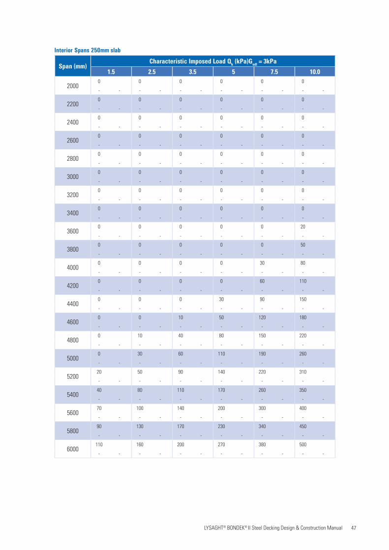
47 LYSAGHT® BONDEK® II Steel Decking Design & Construction Manual
Interior Spans 250mm slab
Span (mm)Characteristic Imposed Load Qk (kPa)Gsdl = 3kPa
1.5 2.5 3.5 5 7.5 10.0
20000 0 0 0 0 0
- - - - - - - - - - - -
22000 0 0 0 0 0
- - - - - - - - - - - -
24000 0 0 0 0 0
- - - - - - - - - - - -
26000 0 0 0 0 0
- - - - - - - - - - - -
28000 0 0 0 0 0
- - - - - - - - - - - -
30000 0 0 0 0 0
- - - - - - - - - - - -
32000 0 0 0 0 0
- - - - - - - - - - - -
34000 0 0 0 0 0
- - - - - - - - - - - -
36000 0 0 0 0 20
- - - - - - - - - - - -
38000 0 0 0 0 50
- - - - - - - - - - - -
40000 0 0 0 30 80
- - - - - - - - - - - -
42000 0 0 0 60 110
- - - - - - - - - - - -
44000 0 0 30 90 150
- - - - - - - - - - - -
46000 0 10 50 120 180
- - - - - - - - - - - -
48000 10 40 80 150 220
- - - - - - - - - - - -
50000 30 60 110 190 260
- - - - - - - - - - - -
520020 50 90 140 220 310
- - - - - - - - - - - -
540040 80 110 170 260 350
- - - - - - - - - - - -
560070 100 140 200 300 400
- - - - - - - - - - - -
580090 130 170 230 340 450
- - - - - - - - - - - -
6000110 160 200 270 380 500
- - - - - - - - - - - -
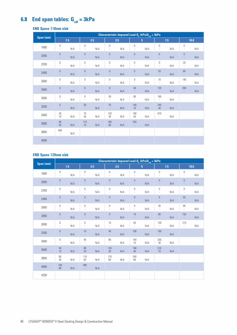
48 LYSAGHT® BONDEK® II Steel Decking Design & Construction Manual
6.8 End span tables: Gsdl = 3kPa
END Spans 110mm slab
Span (mm)Characteristic Imposed Load Qk (kPa)Gsdl = 3kPa
1.5 2.5 3.5 5 7.5 10.0
1800 0- N/A
0- N/A
0- N/A
0- N/A
0- N/A
0- N/A
2000 0- N/A
0- N/A
0- N/A
0- N/A
0- N/A
0- N/A
2200 0- N/A
0- N/A
0- N/A
0- N/A
0- N/A
20- N/A
2400 0- N/A
0- N/A
0- N/A
0- N/A
20- N/A
80- N/A
2600 0- N/A
0- N/A
0- N/A
0- N/A
70- N/A
140- N/A
2800 0- N/A
0- N/A
0- N/A
40- N/A
120- N/A
200- N/A
3000 0- N/A
0- N/A
30- N/A
90- N/A
180- N/A
3200 0- N/A
30- N/A
70- N/A
14010 N/A
24040 N/A
3400 3010 N/A
7030 N/A
12030 N/A
19050 N/A
670- N/A
3600 6050 N/A
11070 N/A
16080 N/A
520- N/A
3800 580- N/A
4000
END Spans 120mm slab
Span (mm)Characteristic Imposed Load Qk (kPa)Gsdl = 3kPa
1.5 2.5 3.5 5 7.5 10.0
1800 0- N/A
0- N/A
0- N/A
0- N/A
0- N/A
0- N/A
2000 0- N/A
0- N/A
0- N/A
0- N/A
0- N/A
0- N/A
2200 0- N/A
0- N/A
0- N/A
0- N/A
0- N/A
0- N/A
2400 0- N/A
0- N/A
0- N/A
0- N/A
0- N/A
40- N/A
2600 0- N/A
0- N/A
0- N/A
0- N/A
30- N/A
90- N/A
2800 0- N/A
0- N/A
0- N/A
10- N/A
80- N/A
150- N/A
3000 0- N/A
0- N/A
10- N/A
50- N/A
130- N/A
210- N/A
3200 0- N/A
10- N/A
40- N/A
100- N/A
190- N/A
3400 0- N/A
40- N/A
80- N/A
14010 N/A
25030 N/A
3600 3010 N/A
8020 N/A
12030 N/A
19040 N/A
31070 N/A
3800 6040 N/A
11060 N/A
17060 N/A
24080 N/A
4000 10080 N/A
480- N/A
4200
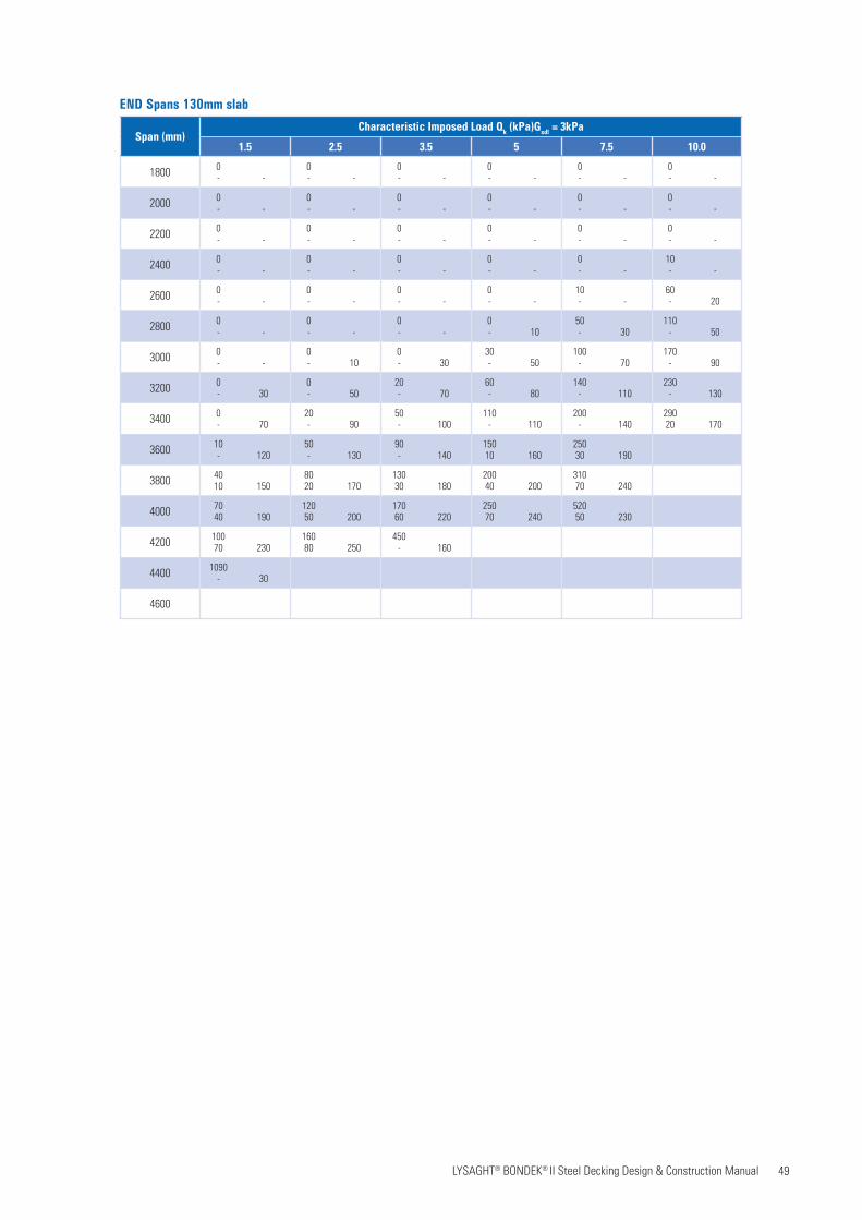
49 LYSAGHT® BONDEK® II Steel Decking Design & Construction Manual
END Spans 130mm slab
Span (mm)Characteristic Imposed Load Qk (kPa)Gsdl = 3kPa
1.5 2.5 3.5 5 7.5 10.0
1800 0- -
0- -
0- -
0- -
0- -
0- -
2000 0- -
0- -
0- -
0- -
0- -
0- -
2200 0- -
0- -
0- -
0- -
0- -
0- -
2400 0- -
0- -
0- -
0- -
0- -
10- -
2600 0- -
0- -
0- -
0- -
10- -
60- 20
2800 0- -
0- -
0- -
0- 10
50- 30
110- 50
3000 0- -
0- 10
0- 30
30- 50
100- 70
170- 90
3200 0- 30
0- 50
20- 70
60- 80
140- 110
230- 130
3400 0- 70
20- 90
50- 100
110- 110
200- 140
29020 170
3600 10- 120
50- 130
90- 140
15010 160
25030 190
3800 4010 150
8020 170
13030 180
20040 200
31070 240
4000 7040 190
12050 200
17060 220
25070 240
52050 230
4200 10070 230
16080 250
450- 160
4400 1090- 30
4600
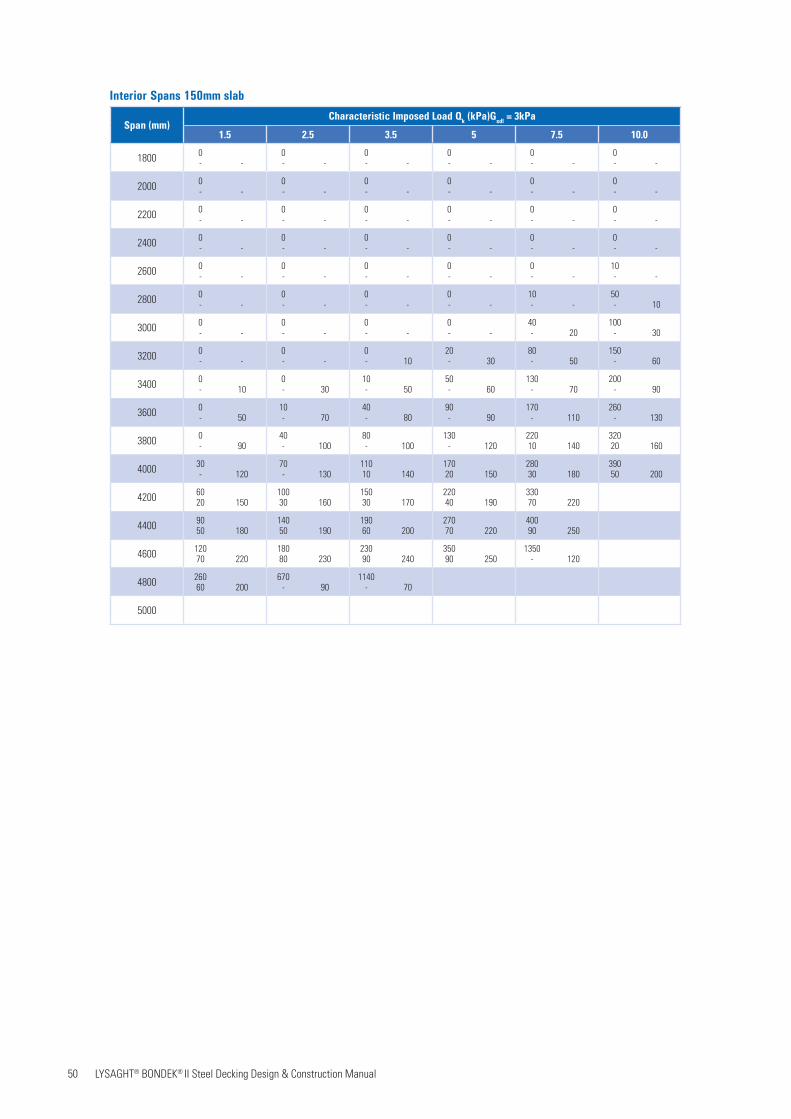
50 LYSAGHT® BONDEK® II Steel Decking Design & Construction Manual
Interior Spans 150mm slab
Span (mm)Characteristic Imposed Load Qk (kPa)Gsdl = 3kPa
1.5 2.5 3.5 5 7.5 10.0
1800 0- -
0- -
0- -
0- -
0- -
0- -
2000 0- -
0- -
0- -
0- -
0- -
0- -
2200 0- -
0- -
0- -
0- -
0- -
0- -
2400 0- -
0- -
0- -
0- -
0- -
0- -
2600 0- -
0- -
0- -
0- -
0- -
10- -
2800 0- -
0- -
0- -
0- -
10- -
50- 10
3000 0- -
0- -
0- -
0- -
40- 20
100- 30
3200 0- -
0- -
0- 10
20- 30
80- 50
150- 60
3400 0- 10
0- 30
10- 50
50- 60
130- 70
200- 90
3600 0- 50
10- 70
40- 80
90- 90
170- 110
260- 130
3800 0- 90
40- 100
80- 100
130- 120
22010 140
32020 160
4000 30- 120
70- 130
11010 140
17020 150
28030 180
39050 200
4200 6020 150
10030 160
15030 170
22040 190
33070 220
4400 9050 180
14050 190
19060 200
27070 220
40090 250
4600 12070 220
18080 230
23090 240
35090 250
1350- 120
4800 26060 200
670- 90
1140- 70
5000
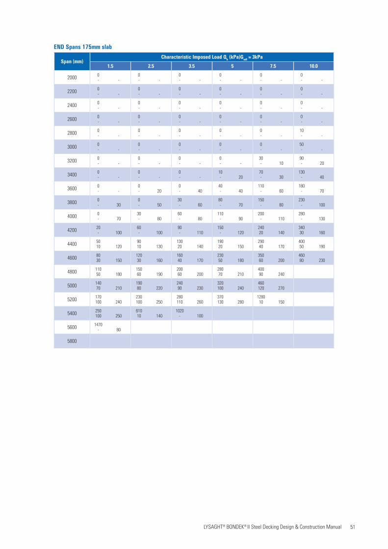
51 LYSAGHT® BONDEK® II Steel Decking Design & Construction Manual
END Spans 175mm slab
Span (mm)Characteristic Imposed Load Qk (kPa)Gsdl = 3kPa
1.5 2.5 3.5 5 7.5 10.0
2000 0- -
0- -
0- -
0- -
0- -
0- -
2200 0- -
0- -
0- -
0- -
0- -
0- -
2400 0- -
0- -
0- -
0- -
0- -
0- -
2600 0- -
0- -
0- -
0- -
0- -
0- -
2800 0- -
0- -
0- -
0- -
0- -
10- -
3000 0- -
0- -
0- -
0- -
0- -
50- -
3200 0- -
0- -
0- -
0- -
30- 10
90- 20
3400 0- -
0- -
0- -
10- 20
70- 30
130- 40
3600 0- -
0- 20
0- 40
40- 40
110- 60
180- 70
3800 0- 30
0- 50
30- 60
80- 70
150- 80
230- 100
4000 0- 70
30- 80
60- 80
110- 90
200- 110
280- 130
4200 20- 100
60- 100
90- 110
150- 120
24020 140
34030 160
4400 5010 120
9010 130
13020 140
19020 150
29040 170
40050 190
4600 8030 150
12030 160
16040 170
23050 180
35060 200
46080 230
4800 11050 180
15060 190
20060 200
28070 210
40090 240
5000 14070 210
19080 220
24090 230
320100 240
460120 270
5200 170100 240
230100 250
280110 260
370130 280
128010 150
5400 250100 250
61010 140
1020- 100
5600 1470- 80
5800
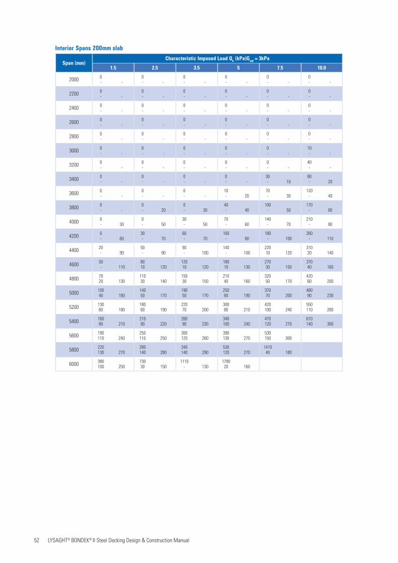
52 LYSAGHT® BONDEK® II Steel Decking Design & Construction Manual
Interior Spans 200mm slab
Span (mm)Characteristic Imposed Load Qk (kPa)Gsdl = 3kPa
1.5 2.5 3.5 5 7.5 10.0
2000 0- -
0- -
0- -
0- -
0- -
0- -
2200 0- -
0- -
0- -
0- -
0- -
0- -
2400 0- -
0- -
0- -
0- -
0- -
0- -
2600 0- -
0- -
0- -
0- -
0- -
0- -
2800 0- -
0- -
0- -
0- -
0- -
0- -
3000 0- -
0- -
0- -
0- -
0- -
10- -
3200 0- -
0- -
0- -
0- -
0- -
40- -
3400 0- -
0- -
0- -
0- -
30- 10
80- 20
3600 0- -
0- -
0- -
10- 20
70- 30
120- 40
3800 0- -
0- 20
0- 30
40- 40
100- 50
170- 60
4000 0- 30
0- 50
30- 50
70- 60
140- 70
210- 80
4200 0- 60
30- 70
60- 70
100- 80
180- 100
260- 110
4400 20- 90
50- 90
90- 100
140- 100
22010 120
31020 140
4600 50- 110
8010 120
12010 120
18010 130
27030 150
37040 160
4800 7020 130
11030 140
15030 150
21040 160
32050 170
42060 200
5000 10040 160
14050 170
19050 170
25060 190
37070 200
48090 230
5200 13060 180
18060 190
22070 200
30080 210
420100 240
550110 260
5400 16080 210
21090 220
26090 230
340100 240
470120 270
610140 300
5600 190110 240
250110 250
300120 260
390130 270
530150 300
5800 220130 270
280140 280
340140 290
530120 270
141040 180
6000 380100 250
73030 150
1110- 130
178020 160

53 LYSAGHT® BONDEK® II Steel Decking Design & Construction Manual
END Spans 250mm slab
Span (mm)Characteristic Imposed Load Qk (kPa)Gsdl = 3kPa
1.5 2.5 3.5 5 7.5 10.0
2000 0- -
0- -
0- -
0- -
0- -
0- -
2200 0- -
0- -
0- -
0- -
0- -
0- -
2400 0- -
0- -
0- -
0- -
0- -
0- -
2600 0- -
0- -
0- -
0- -
0- -
0- -
2800 0- -
0- -
0- -
0- -
0- -
0- -
3000 0- -
0- -
0- -
0- -
0- -
0- -
3200 0- -
0- -
0- -
0- -
0- -
0- -
3400 0- -
0- -
0- -
0- -
0- -
20- -
3600 0- -
0- -
0- -
0- -
10- -
50- -
3800 0- -
0- -
0- -
0- -
40- 10
90- 20
4000 0- -
0- -
0- 10
20- 20
70- 30
120- 40
4200 0- 10
0- 30
10- 40
40- 40
100- 50
160- 60
4400 0- 40
10- 50
30- 60
70- 60
140- 70
200- 80
4600 10- 60
30- 70
60- 70
100- 80
170- 90
250- 100
4800 30- 80
60- 90
90- 90
140- 100
21010 110
29010 120
5000 50- 110
8010 110
120 10 110
17010 120
25020 130
34030 140
5200 8020 120
11020 130
15030 130
20030 140
29040 160
39050 170
5400 10040 150
14040 150
18040 160
24050 170
34060 180
44070 200
5600 13060 170
17060 180
21060 180
28070 190
38080 210
49090 220
5800 16070 190
20080 200
25080 210
32090 210
430100 230
550120 250
6000 180100 220
230100 230
280100 230
360110 240
480130 260
610140 280

54 LYSAGHT® BONDEK® II Steel Decking Design & Construction Manual
Bearing of BONDEK®II(Not less than 100mmwhere sheeting iscontinuous)
Cover
Bearing of BONDEK®II(Not less than 50mmat end of sheets)
BONDEK®II
Concrete slab
Slab
dep
th
Props whererequired
Slab span(Interior span)
Props whererequired
Slab span(End span)
Cover
7. CONSTRUCTION AND DETAILING
The construction of LYSAGHT® BONDEK® ll composite slabs follows simple, familiar and widely-accepted building practice. Workers can readily acquire the skills necessary to install BONDEK® ll formwork and finish the composite slab. Construction workers will normally be supplied with fully detailed drawings showing the direction of the ribs, other reinforcement and all supporting details.
7.1 Safety BONDEK® ll is available in long lengths, so large areas can be quickly and easily covered to form a safe working platform during construction. One level of formwork gives immediate protection from the weather, and safety to people working on the floor below. The minimal propping requirements provide a relatively open area to the floor below.
The bold embossments along the top of the ribs of BONDEK® ll enhance safety by reducing the likelihood of workers slipping.
It is commonsense to work safely, protecting yourself and workmates from accidents on the site. Safety includes the practices you use; as well as personal protection of eyes and skin from sunburn, and hearing from noise. For personal safety,
Figure 7.1 BONDEK® ll Installation guidelines
and to protect the surface finish of BONDEK® ll, wear clean dry gloves. Don’t slide sheets over rough surfaces or over each other. Always carry tools, don’t drag them.
Occupational health and safety laws enforce safe working conditions in most locations. Laws in every state require you to have fall protection which includes safety mesh, personal harnesses and perimeter guardrails where they are appropriate. We recommend that you adhere strictly to all laws that apply to your site.
BONDEK® ll is capable of withstanding temporary construction loads including the mass of workmen, equipment and materials all in accordance with SS EN 1999-1-6:2009. However, it is good construction practice to ensure protection from concentrated loads, such as barrows, by use of some means such as planks and/or boards.
7.2 Care and storage before installation
BONDEK® ll is delivered in strapped bundles. If not required for immediate use, stack sheets or bundles neatly and clear of the ground, on a slight slope to allow drainage of water. If left in the open, protect with waterproof covers.
7.3 Installation of BONDEK® II sheeting on-site
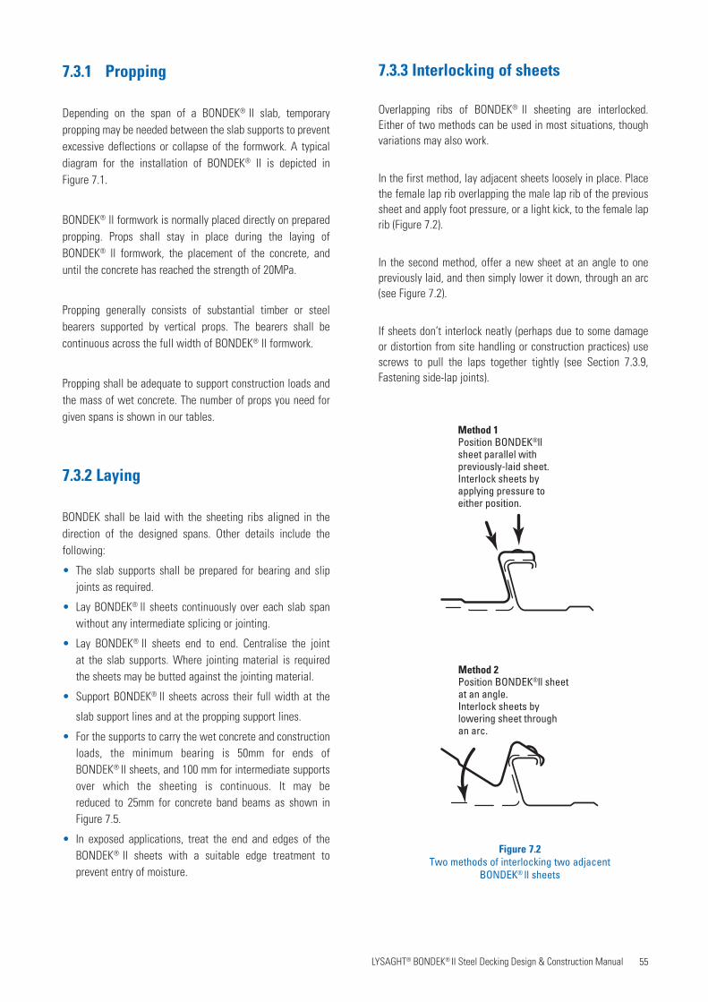
55 LYSAGHT® BONDEK® II Steel Decking Design & Construction Manual
7.3.1 Propping
Depending on the span of a BONDEK® ll slab, temporary propping may be needed between the slab supports to prevent excessive deflections or collapse of the formwork. A typical diagram for the installation of BONDEK® ll is depicted in Figure 7.1.
BONDEK® ll formwork is normally placed directly on prepared propping. Props shall stay in place during the laying of BONDEK® ll formwork, the placement of the concrete, and until the concrete has reached the strength of 20MPa.
Propping generally consists of substantial timber or steel bearers supported by vertical props. The bearers shall be continuous across the full width of BONDEK® ll formwork.
Propping shall be adequate to support construction loads and the mass of wet concrete. The number of props you need for given spans is shown in our tables.
7.3.2 Laying
BONDEK shall be laid with the sheeting ribs aligned in the direction of the designed spans. Other details include the following:
• The slab supports shall be prepared for bearing and slip joints as required.
• Lay BONDEK® ll sheets continuously over each slab span without any intermediate splicing or jointing.
• Lay BONDEK® ll sheets end to end. Centralise the joint at the slab supports. Where jointing material is required the sheets may be butted against the jointing material.
• Support BONDEK® ll sheets across their full width at the
slab support lines and at the propping support lines.
• For the supports to carry the wet concrete and construction loads, the minimum bearing is 50mm for ends of BONDEK® ll sheets, and 100 mm for intermediate supports over which the sheeting is continuous. It may be reduced to 25mm for concrete band beams as shown in Figure 7.5.
• In exposed applications, treat the end and edges of the BONDEK® ll sheets with a suitable edge treatment to prevent entry of moisture.
7.3.3 Interlocking of sheets
Overlapping ribs of BONDEK® ll sheeting are interlocked. Either of two methods can be used in most situations, though variations may also work.
In the first method, lay adjacent sheets loosely in place. Place the female lap rib overlapping the male lap rib of the previous sheet and apply foot pressure, or a light kick, to the female lap rib (Figure 7.2).
In the second method, offer a new sheet at an angle to one previously laid, and then simply lower it down, through an arc (see Figure 7.2).
If sheets don’t interlock neatly (perhaps due to some damage or distortion from site handling or construction practices) use screws to pull the laps together tightly (see Section 7.3.9, Fastening side-lap joints).
Figure 7.2Two methods of interlocking two adjacent
BONDEK® ll sheets
Method 1Position BONDEK®ll sheet parallel withpreviously-laid sheet.Interlock sheets byapplying pressure toeither position.
Method 2Position BONDEK®ll sheetat an angle.Interlock sheets bylowering sheet throughan arc.

56 LYSAGHT® BONDEK® II Steel Decking Design & Construction Manual
Fixing at end of sheets
Fixing at intermediate slab supportsover which the sheeting is continuous
Figure 7.3Positions for fixing BONDEK® ll sheet
to steel framing
7.3.4 Securing the sheeting platform
BONDEK® ll shall be securely fixed to supporting structures using:
• weights;
• screws or nails into the propping bearers; or
• Spot welding
Take care if you use penetrating fasteners (such as screws and nails) because they can make removal of the props difficult, and perhaps result in damage to the BONDEK® ll.
7.3.5 Installing BONDEK®II on steel frames
BONDEK® ll may be installed directly on erected structural steelwork.
General fastening of BONDEK® ll
To provide uplift resistance or lateral restraint, the sheeting may be fixed to the structural steel using spot welds, or fasteners such as drive nails or self-drilling screws.
At a movement joint, the sheeting is not continuous over the support. If one sheet is fastened at the joint, the other is not.
Place the fixings (fasteners and spot welds) in the flat areas of the pans adjacent to the ribs or between the flutes. The frequency of fixings depends on wind or seismic conditions and good building practice.
One fixing system is as follows.
• At the end of sheets: use a fixing at every rib (Figure 7.3).
• At each intermediate slab support over which the sheeting is continuous: use a fixing at the ribs on both edges (Figure 7.3).
• Fix BONDEK® ll with drive nails, self-drilling screws or spot welds.
• Drive nails should be powder-activated, steel nails 4mm nominal diameter, suitable for structural steel of 4mm thickness or greater.
• For structural steel up to 12mm thick, use 12-24 x 38mm self-drilling self-tapping hexagon head screws.
• For structural steel over 12mm thick, pre-drill and use 12-24 x16mm hexagon head screws.
• Spot welds should be 12mm minimum diameter. Use 3.25mm diameter cellulose, iron powder AC/DC high penetration electrodes or equivalent. Surfaces to be welded shall be free of loose material and foreign matter. Where the BONDEK® ll soffit or the structural steelwork has a pre- painted surface, securing methods other than welding may be more appropriate. Take suitable safety precautions against fumes during welding zinc coated products.
Fastening composite beams
In projects of composite beam construction the BONDEK®ll sheeting shall be fastened to supports. This provision requires a fixing in each pan at each composite beam.
Stud welding through the sheet has been considered a suitable securing method for the sheeting in a composite beam; however some preliminary fixing by one of the methods mentioned above is necessary to secure the sheeting prior to the stud welding. Some relevant welding requirements are:
• Zinc coating on sheeting not to exceed Z450;
• Mating surfaces of steel beam and sheeting to be cleaned of scale, rust, moisture, paint, overspray, primer, sand, mud or other contamination that would prevent direct contact between the parent material and the BONDEK® ll;
• Welding shall be done in dry conditions by a certified welder;
• For pre-painted BONDEK® ll sheets, special welding procedures may be necessary; and
• For sheets transverse to beams, stud welding shall be between pan flutes to ensure there is no gap between mating surfaces.
NOTE: Welding may void warranty as well as damagingsteel support.
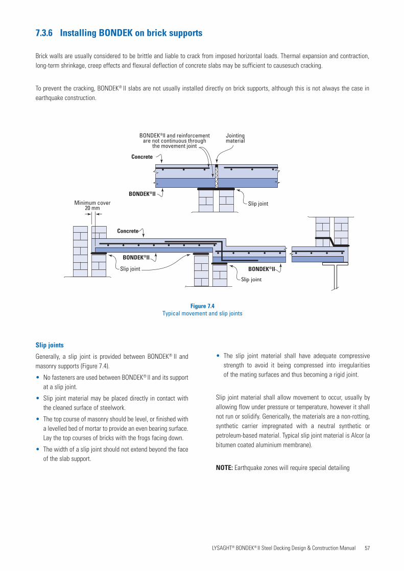
57 LYSAGHT® BONDEK® II Steel Decking Design & Construction Manual
7.3.6 Installing BONDEK on brick supports
Brick walls are usually considered to be brittle and liable to crack from imposed horizontal loads. Thermal expansion and contraction, long-term shrinkage, creep effects and flexural deflection of concrete slabs may be sufficient to causesuch cracking.
To prevent the cracking, BONDEK® ll slabs are not usually installed directly on brick supports, although this is not always the case in earthquake construction.
Jointingmaterial
BONDEK®ll and reinforcementare not continuous through
the movement joint
Slip joint
BONDEK®ll
Concrete
Minimum cover20 mm
Concrete
BONDEK®ll
BONDEK®llSlip joint
Slip joint
Figure 7.4 Typical movement and slip joints
Slip joints
Generally, a slip joint is provided between BONDEK® ll and masonry supports (Figure 7.4).
• No fasteners are used between BONDEK® ll and its support at a slip joint.
• Slip joint material may be placed directly in contact with the cleaned surface of steelwork.
• The top course of masonry should be level, or finished with a levelled bed of mortar to provide an even bearing surface. Lay the top courses of bricks with the frogs facing down.
• The width of a slip joint should not extend beyond the face of the slab support.
• The slip joint material shall have adequate compressive strength to avoid it being compressed into irregularities of the mating surfaces and thus becoming a rigid joint.
Slip joint material shall allow movement to occur, usually by allowing flow under pressure or temperature, however it shall not run or solidify. Generically, the materials are a non-rotting, synthetic carrier impregnated with a neutral synthetic or petroleum-based material. Typical slip joint material is Alcor (a bitumen coated aluminium membrane).
NOTE: Earthquake zones will require special detailing
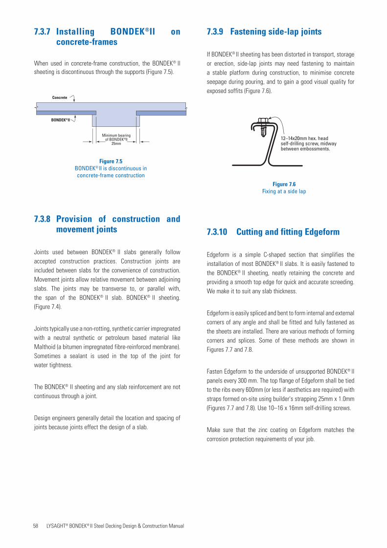
58 LYSAGHT® BONDEK® II Steel Decking Design & Construction Manual
7.3.9 Fastening side-lap joints
If BONDEK® ll sheeting has been distorted in transport, storage or erection, side-lap joints may need fastening to maintain a stable platform during construction, to minimise concrete seepage during pouring, and to gain a good visual quality for exposed soffits (Figure 7.6).
7.3.10 Cutting and fitting Edgeform
Edgeform is a simple C-shaped section that simplifies the installation of most BONDEK® ll slabs. It is easily fastened to the BONDEK® ll sheeting, neatly retaining the concrete and providing a smooth top edge for quick and accurate screeding. We make it to suit any slab thickness.
Edgeform is easily spliced and bent to form internal and external corners of any angle and shall be fitted and fully fastened as the sheets are installed. There are various methods of forming corners and splices. Some of these methods are shown in Figures 7.7 and 7.8.
Fasten Edgeform to the underside of unsupported BONDEK® ll panels every 300 mm. The top flange of Edgeform shall be tied to the ribs every 600mm (or less if aesthetics are required) with straps formed on-site using builder's strapping 25mm x 1.0mm (Figures 7.7 and 7.8). Use 10–16 x 16mm self-drilling screws.
Make sure that the zinc coating on Edgeform matches the corrosion protection requirements of your job.
Concrete
BONDEK®ll
Minimum bearingof BONDEK®ll
25mm
Figure 7.5 BONDEK® ll is discontinuous in concrete-frame construction
7.3.7 Installing BONDEK®II on concrete-frames
When used in concrete-frame construction, the BONDEK® ll sheeting is discontinuous through the supports (Figure 7.5).
7.3.8 Provision of construction and movement joints
Joints used between BONDEK® ll slabs generally follow accepted construction practices. Construction joints are included between slabs for the convenience of construction. Movement joints allow relative movement between adjoining slabs. The joints may be transverse to, or parallel with, the span of the BONDEK® ll slab. BONDEK® ll sheeting.(Figure 7.4).
Joints typically use a non-rotting, synthetic carrier impregnated with a neutral synthetic or petroleum based material like Malthoid (a bitumen impregnated fibre-reinforced membrane). Sometimes a sealant is used in the top of the joint forwater tightness.
The BONDEK® ll sheeting and any slab reinforcement are not continuous through a joint.
Design engineers generally detail the location and spacing of joints because joints effect the design of a slab.
12–14x20mm hex. headself-drilling screw, midwaybetween embossments.
Figure 7.6Fixing at a side lap
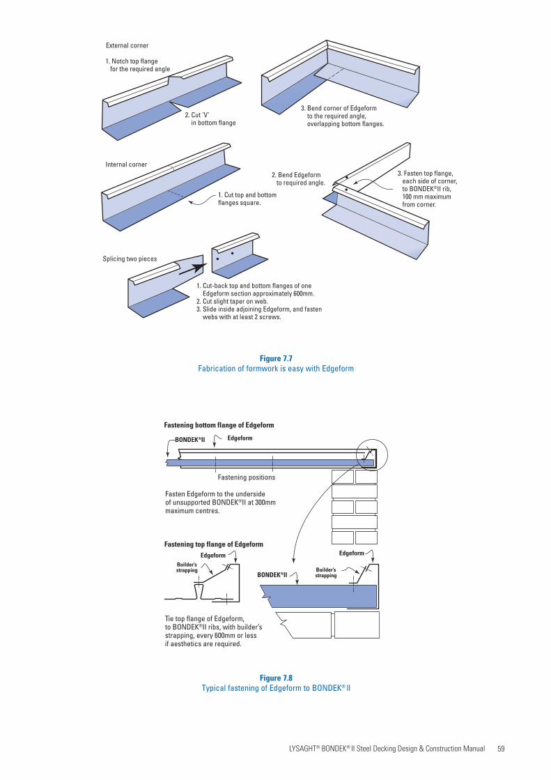
59 LYSAGHT® BONDEK® II Steel Decking Design & Construction Manual
Figure 7.7Fabrication of formwork is easy with Edgeform
Tie top flange of Edgeform,to BONDEK®II ribs, with builder’s strapping, every 600mm or lessif aesthetics are required.
Fastening positions
Fasten Edgeform to the undersideof unsupported BONDEK®II at 300mmmaximum centres.
EdgeformBONDEK®II
BONDEK®II
Edgeform Edgeform
Builder’sstrapping
Builder’sstrapping
Fastening bottom flange of Edgeform
Fastening top flange of Edgeform
Figure 7.8Typical fastening of Edgeform to BONDEK® ll
External corner
Internal corner
Splicing two pieces
1. Notch top flange for the required angle
2. Cut 'V' in bottom flange
3. Bend corner of Edgeform to the required angle, overlapping bottom flanges.
1. Cut top and bottomflanges square.
1. Cut-back top and bottom flanges of one Edgeform section approximately 600mm.2. Cut slight taper on web.3. Slide inside adjoining Edgeform, and fasten webs with at least 2 screws.
2. Bend Edgeform to required angle.
3. Fasten top flange, each side of corner, to BONDEK®II rib, 100 mm maximum from corner.

60 LYSAGHT® BONDEK® II Steel Decking Design & Construction Manual
Minimise the quantity and size of holes through BONDEK® ll sheeting, by hanging services from the underside of
BONDEK® ll using accessories such as Bon-nut and Bonwedge.
Top-face reinforcement
Bottom-face reinforcement
Zones for pipes and other itemslaid parallel with the ribs
Zone for pipes laid across the ribs(between top and bottom reinforcement)
Concrete
BONDEK®ll
Figure 7.9Zones for the location of holes through BONDEK® ll
Table 7.1Location of items within the slab (Figure 7.9)
Items Location
Pipes parallel with the ribs and other items
• Between the ribs; and
• below the top-facereinforcements; and
• above the pans and flutes of the BONDEK® ll
Pipes across the ribsIn the space between the top-face and bottom-face reinforcements
(if there is no bottom-face reinforcement, above the top of the ribs)
7.3.12 Items embedded in slabs
Generally use items in a manner which complies with Eurocodes. Included are pipes and conduits, sleeves, inserts, holding-down bolts, chairs and other supports, plastic strips for plasterboard attachment, contraction joint material and many more.
7.3.11 Cutting of sheeting
It is easy to cut LYSAGHT® BONDEK® ll sheets to fit. Use a power saw fitted with an abrasive disc or metal cutting blade. Initially lay the sheet with its ribs down, cut through the pans and part-through the ribs, then turn over and finish by cutting the tops of the ribs.
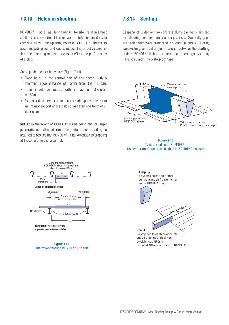
61 LYSAGHT® BONDEK® II Steel Decking Design & Construction Manual
7.3.13 Holes in sheeting
BONDEK®ll acts as longitudinal tensile reinforcement similarly to conventional bar or fabric reinforcement does in concrete slabs. Consequently, holes in BONDEK®ll sheets, to accommodate pipes and ducts, reduce the effective area of the steel sheeting and can adversely effect the performance of a slab.
Some guidelines for holes are: (Figure 7.11)
• Place holes in the central pan of any sheet, with a minimum edge distance of 15mm from the rib gap.
• Holes should be round, with a maximum diameter of 150mm.
• For slabs designed as a continuous slab: space holes from an interior support of the slab no less than one tenth of a clear span.
NOTE: In the event of BONDEK® ll ribs being cut for larger penetrations, sufficient reinforcing steel and detailing is required to replace lost BONDEK® ll ribs. Attention to propping at these locations is essential.
7.3.14 Sealing
Seepage of water or fine concrete slurry can be minimised by following common construction practices. Generally gaps are sealed with waterproof tape, or Bonfill (Figure 7.10) or by sandwiching contraction joint material between the abutting ends of BONDEK® ll sheet. If there is a sizeable gap you may have to support the waterproof tape.
Zone for holes throughBONDEK®II sheet in central pan
Max. diameter 150mm
15mmminimum
Ln
BONDEK®II
Location of holes relative tosupports in continuous slabs
Location of holes in sheet
Interior supports
Zone for holesin continuous slabs
Minimum0.1 Ln
Minimum0.1 Ln
BonfillPolystyrene foam stops concreteand air entering ends of ribs.Stock length: 1200mmRequired: 300mm per sheet of BONDEK®II
End plugPolyethylene end plug stops concrete and air from enteringend of BONDEK®II ribs.
Sizeable gap betweenBONDEK®II sheets Where necessary, insert
Bonfill into ribs to support tape
Waterproof tapeover gap
Figure 7.10Typical sealing of BONDEK® ll
Use waterproof tape to seal joints in BONDEK® ll sheets
Figure 7.11Penetration through BONDEK® ll sheets.

62 LYSAGHT® BONDEK® II Steel Decking Design & Construction Manual
Figure 7.12Typical cross section of a slab showing common terms.
Reinforcementdepth
Concretecover
Concrete
BONDEK®II
Fabricreinforcement(mesh)
Deformed barreinforcement
Dept
h of
com
posi
te s
lab
(D)
Longitudinal reinforcement(parallel with ribs)
Transverse reinforcement(90° to ribs)
Top-facereinforcement
Bottom-facereinforcement(Single spans)
7.3.15 Inspection
BONDEK® ll sheeting acts as longitudinal tensile reinforcement.
The condition of sheeting should be inspected before concrete is poured.
We recommend regular qualified inspection during the installation, to be sure that the sheeting is installed in accordance with this publication and good building practice.
7.4 Positioning and support of reinforcement
Reinforcement in slabs carries and distributes the design loads and to control cracking. Reinforcement is generally described as transverse and longitudinal in relation to span, but other reinforcement required for trimming may be positioned in other orientations. Figure 7.12 shows a typical cross-section of a BONDEK® ll composite slab and associated terms.
Reinforcement shall be properly positioned, lapped where necessary to ensure continuity, and tied to prevent displacement during construction.
To ensure the specified minimum concrete cover, the uppermost layer of reinforcement shall be positioned and tied to prevent displacement during construction (Section 4.4 of this Manual).
Splicing of conventional reinforcement shall be in accordance with SS EN 1992-1-1:2008 Section 8 (Splicing of reinforcement).
Where fabric is used in thin slabs, or where fabric is used to act as both longitudinal and transverse reinforcement, pay particular attention the required minimum concrete cover and the required design reinforcement depth at the splices-splice bars are a prudent addition.
Always place chairs and spacers on pan areas. Depending upon the type of chair and its loading, it may be necessary to use plates under chairs to protect the BONDEK® ll, particularly where the soffit will be exposed. Transverse reinforcement may be used for spacing or supporting longitudinal reinforcement.joint material and many more.
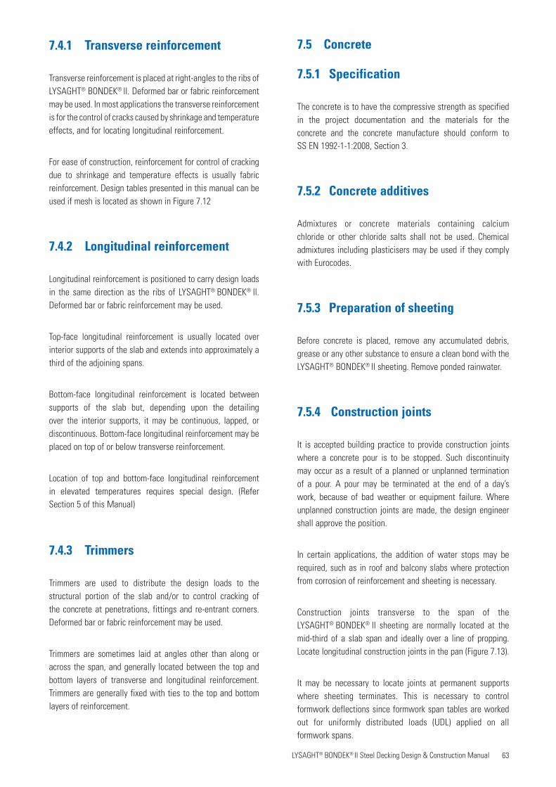
63 LYSAGHT® BONDEK® II Steel Decking Design & Construction Manual
7.4.1 Transverse reinforcement
Transverse reinforcement is placed at right-angles to the ribs of LYSAGHT® BONDEK® ll. Deformed bar or fabric reinforcement may be used. In most applications the transverse reinforcement is for the control of cracks caused by shrinkage and temperature effects, and for locating longitudinal reinforcement.
For ease of construction, reinforcement for control of cracking due to shrinkage and temperature effects is usually fabric reinforcement. Design tables presented in this manual can be used if mesh is located as shown in Figure 7.12
7.4.2 Longitudinal reinforcement
Longitudinal reinforcement is positioned to carry design loads in the same direction as the ribs of LYSAGHT® BONDEK® ll. Deformed bar or fabric reinforcement may be used.
Top-face longitudinal reinforcement is usually located over interior supports of the slab and extends into approximately a third of the adjoining spans.
Bottom-face longitudinal reinforcement is located between supports of the slab but, depending upon the detailing over the interior supports, it may be continuous, lapped, or discontinuous. Bottom-face longitudinal reinforcement may be placed on top of or below transverse reinforcement.
Location of top and bottom-face longitudinal reinforcement in elevated temperatures requires special design. (ReferSection 5 of this Manual)
7.4.3 Trimmers Trimmers
Trimmers are used to distribute the design loads to the structural portion of the slab and/or to control cracking of the concrete at penetrations, fittings and re-entrant corners. Deformed bar or fabric reinforcement may be used.
Trimmers are sometimes laid at angles other than along or across the span, and generally located between the top and bottom layers of transverse and longitudinal reinforcement. Trimmers are generally fixed with ties to the top and bottom layers of reinforcement.
7.5 Concrete
7.5.1 Specification
The concrete is to have the compressive strength as specified in the project documentation and the materials for the concrete and the concrete manufacture should conform toSS EN 1992-1-1:2008, Section 3.
7.5.2 Concrete additives
Admixtures or concrete materials containing calcium chloride or other chloride salts shall not be used. Chemical admixtures including plasticisers may be used if they complywith Eurocodes.
7.5.3 Preparation of sheeting
Before concrete is placed, remove any accumulated debris, grease or any other substance to ensure a clean bond with the LYSAGHT® BONDEK® ll sheeting. Remove ponded rainwater.
7.5.4 Construction joints
It is accepted building practice to provide construction joints where a concrete pour is to be stopped. Such discontinuity may occur as a result of a planned or unplanned termination of a pour. A pour may be terminated at the end of a day’s work, because of bad weather or equipment failure. Where unplanned construction joints are made, the design engineer shall approve the position.
In certain applications, the addition of water stops may be required, such as in roof and balcony slabs where protection from corrosion of reinforcement and sheeting is necessary.
Construction joints transverse to the span of theLYSAGHT® BONDEK® ll sheeting are normally located at the mid-third of a slab span and ideally over a line of propping. Locate longitudinal construction joints in the pan (Figure 7.13).
It may be necessary to locate joints at permanent supports where sheeting terminates. This is necessary to control formwork deflections since formwork span tables are worked out for uniformly distributed loads (UDL) applied on allformwork spans.
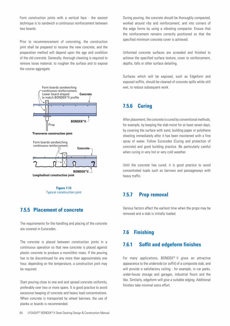
64 LYSAGHT® BONDEK® II Steel Decking Design & Construction Manual
Form construction joints with a vertical face - the easiest technique is to sandwich a continuous reinforcement between two boards.
Prior to recommencement of concreting, the construction joint shall be prepared to receive the new concrete, and the preparation method will depend upon the age and condition of the old concrete. Generally, thorough cleaning is required to remove loose material, to roughen the surface and to expose the course aggregate.
Figure 7.13Typical construction joint
Concrete
BONDEK®llProp
Form boards sandwichingcontinuous reinforcement.Lower board shapedto match BONDEK®II profile
Concrete
BONDEK®ll
Form boards sandwichingcontinuous reinforcement.
Transverse construction joint
Longitudinal construction joint
7.5.5 Placement of concrete
The requirements for the handling and placing of the concrete are covered in Eurocodes.
The concrete is placed between construction joints in a continuous operation so that new concrete is placed against plastic concrete to produce a monolithic mass. If the pouring has to be discontinued for any more than approximately one hour, depending on the temperature, a construction joint may be required.
Start pouring close to one end and spread concrete uniformly, preferably over two or more spans. It is good practice to avoid excessive heaping of concrete and heavy load concentrations. When concrete is transported by wheel barrows, the use of planks or boards is recommended.
During pouring, the concrete should be thoroughly compacted, worked around ribs and reinforcement, and into corners of the edge forms by using a vibrating compactor. Ensure that the reinforcement remains correctly positioned so that the specified minimum concrete cover is achieved.
Unformed concrete surfaces are screeded and finished to achieve the specified surface texture, cover to reinforcement, depths, falls or other surface detailing.
Surfaces which will be exposed, such as Edgeform and exposed soffits, should be cleaned of concrete spills while still wet, to reduce subsequent work.
7.5.6 Curing
After placement, the concrete is cured by conventional methods, for example, by keeping the slab moist for at least seven days, by covering the surface with sand, building paper or polythene sheeting immediately after it has been moistened with a fine spray of water. Follow Eurocodes (Curing and protection of concrete) and good building practice. Be particularly careful when curing in very hot or very cold weather.
Until the concrete has cured, it is good practice to avoid concentrated loads such as barrows and passageways with heavy traffic.
7.5.7 Prop removal
Various factors affect the earliest time when the props may be removed and a slab is initially loaded.
7.6 Finishing
7.6.1 Soffit and edgeform finishes
For many applications, BONDEK® ll gives an attractive appearance to the underside (or soffit) of a composite slab, and will provide a satisfactory ceiling - for example, in car parks, under-house storage and garages, industrial floors and the like. Similarly, edgeform will give a suitable edging. Additional finishes take minimal extra effort.
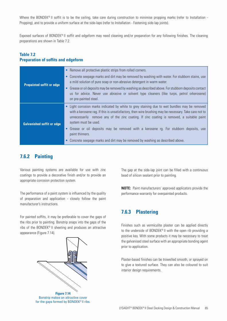
65 LYSAGHT® BONDEK® II Steel Decking Design & Construction Manual
Where the BONDEK® ll soffit is to be the ceiling, take care during construction to minimise propping marks (refer to Installation - Propping), and to provide a uniform surface at the side-laps (refer to Installation - Fastening side-lap joints).
Exposed surfaces of BONDEK® ll soffit and edgeform may need cleaning and/or preparation for any following finishes. The cleaning preparations are shown in Table 7.2.
7.6.2 Painting
Various painting systems are available for use with zinc coatings to provide a decorative finish and/or to provide an appropriate corrosion protection system.
The performance of a paint system is influenced by the quality of preparation and application - closely follow the paint manufacturer’s instructions.
For painted soffits, it may be preferable to cover the gaps of the ribs prior to painting. Bonstrip snaps into the gaps of the ribs of the BONDEK® ll sheeting and produces an attractive appearance (Figure 7.14).
The gap at the side-lap joint can be filled with a continuous bead of silicon sealant prior to painting.
NOTE: Paint manufacturers' approved applicators provide the performance warranty for overpainted products.
7.6.3 Plastering
Finishes such as vermiculite plaster can be applied directly to the underside of BONDEK® ll with the open rib providing a positive key. With some products it may be necessary to treat the galvanised steel surface with an appropriate bonding agent prior to application.
Plaster-based finishes can be trowelled smooth, or sprayed on to give a textured surface. They can also be coloured to suit interior design requirements.
Figure 7.14Bonstrip makes an attractive cover
for the gaps formed by BONDEK® ll ribs.
Prepainted soffit or edge
Galvanished soffit or edge
Table 7.2Preparation of soffits and edgeform
• Remove all protective plastic strips from rolled corners.
• Concrete seepage marks and dirt may be removed by washing with water. For stubborn stains, use a mild solution of pure soap or non-abrasive detergent in warm water.
• Grease or oil deposits may be removed by washing as described above. For stubborn deposits contact us for advice. Never use abrasive or solvent type cleaners (like turps, petrol orkerosene) on pre-painted steel.
• Light corrosion marks indicated by white to grey staining due to wet bundles may be removed with a kerosene rag. If this is unsatisfactory, then wire brushing may be necessary. Take care not to unnecessarily remove any of the zinc coating. If zinc coating is removed, a suitable paint system must be used.
• Grease or oil deposits may be removed with a kerosene rg. For stubborn deposits, use paint thinners.
• Concrete seepage marks and dirt may be removed by washing as described above.
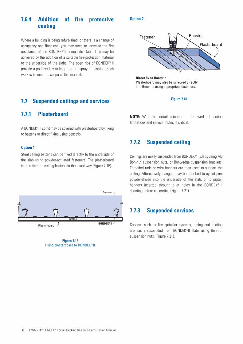
66 LYSAGHT® BONDEK® II Steel Decking Design & Construction Manual
Plaster board
Concrete
BONDEK®ll
Batten
Figure 7.15Fixing plasterboard to BONDEK® ll.
Figure 7.16
Direct fix to BonstripPlasterboard may also be screwed directly into Bonstrip using appropriate fasteners.
Plasterboard
BonstripFastener
7.6.4 Addition of fire protective coating
Where a building is being refurbished, or there is a change of occupancy and floor use, you may need to increase the fire resistance of the BONDEK® ll composite slabs. This may be achieved by the addition of a suitable fire-protection material to the underside of the slabs. The open ribs of BONDEK® ll provide a positive key to keep the fire spray in position. Such work is beyond the scope of this manual.
7.7 Suspended ceilings and services
7.7.1 Plasterboard
A BONDEK® ll soffit may be covered with plasterboard by fixing to battens or direct fixing using bonstrip.
Option 1
Steel ceiling battens can be fixed directly to the underside of the slab using powder-actuated fasteners. The plasterboard is then fixed to ceiling battens in the usual way (Figure 7.15).
Option 2:
NOTE: With this detail attention to formwork, deflection limitations and service routes is critical.
7.7.2 Suspended ceiling
Ceilings are easily suspended from BONDEK® ll slabs using M6 Bon-nut suspension nuts, or Bonwedge suspension brackets. Threaded rods or wire hangers are then used to support the ceiling. Alternatively, hangers may be attached to eyelet pins powder-driven into the underside of the slab, or to pigtail hangers inserted through pilot holes in the BONDEK® ll sheeting before concreting (Figure 7.21).
7.7.3 Suspended services
Services such as fire sprinkler systems, piping and ducting are easily suspended from BONDEK®ll slabs using Bon-nut suspension nuts. (Figure 7.21).
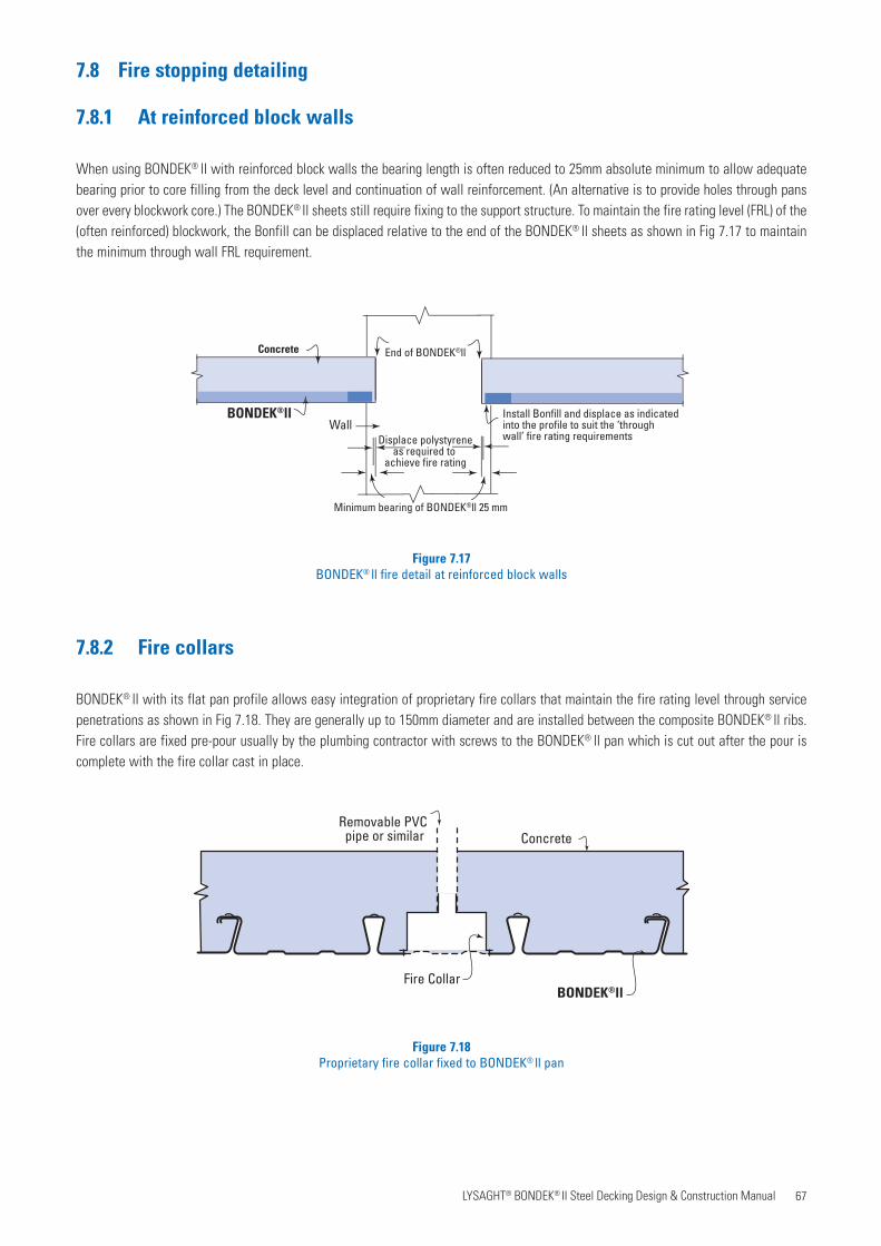
67 LYSAGHT® BONDEK® II Steel Decking Design & Construction Manual
Concrete
Install Bonfill and displace as indicated into the profile to suit the ‘through wall’ fire rating requirements
BONDEK®ll
Minimum bearing of BONDEK®ll 25 mm
End of BONDEK®ll
Displace polystyreneas required to
achieve fire rating
Wall
Figure 7.17BONDEK® ll fire detail at reinforced block walls
Figure 7.18Proprietary fire collar fixed to BONDEK® ll pan
Concrete
BONDEK®llFire Collar
Removable PVC pipe or similar
7.8 Fire stopping detailing
7.8.1 At reinforced block walls
When using BONDEK® ll with reinforced block walls the bearing length is often reduced to 25mm absolute minimum to allow adequate bearing prior to core filling from the deck level and continuation of wall reinforcement. (An alternative is to provide holes through pans over every blockwork core.) The BONDEK® ll sheets still require fixing to the support structure. To maintain the fire rating level (FRL) of the (often reinforced) blockwork, the Bonfill can be displaced relative to the end of the BONDEK® ll sheets as shown in Fig 7.17 to maintain the minimum through wall FRL requirement.
7.8.2 Fire collars
BONDEK® ll with its flat pan profile allows easy integration of proprietary fire collars that maintain the fire rating level through service penetrations as shown in Fig 7.18. They are generally up to 150mm diameter and are installed between the composite BONDEK® ll ribs. Fire collars are fixed pre-pour usually by the plumbing contractor with screws to the BONDEK® ll pan which is cut out after the pour is complete with the fire collar cast in place.
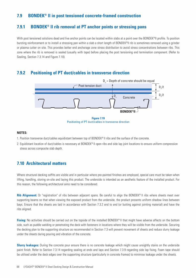
68 LYSAGHT® BONDEK® II Steel Decking Design & Construction Manual
7.9 BONDEK® ll in post tensioned concrete-framed construction
7.9.1 BONDEK® ll rib removal at PT anchor points or stressing pans
With post tensioned solutions dead and live anchor points can be located within slabs at a point over the BONDEK®ll profile. To position bursting reinforcement or to install a stressing pan within a slab a short length of BONDEK®ll rib is sometimes removed using a grinder or plasma cutter on site. This provides better end anchorage zone stress distribution to avoid stress concentrations between ribs. This zone where the rib is removed is sealed (usually with tape) before placing the post tensioning end termination component. (Refer to Sealing, Section 7.3.14 and Figure 7.10).
7.9.2 Positioning of PT duct/cables in transverse direction
Post tension duct
Concrete
BONDEK®II
Dc = Depth of concrete should be equal
Dc/2
DcDc/2
NOTES:
1. Position transverse duct/cables equidistant between top of BONDEK® ll ribs and the surface of the concrete.
2. Equidistant location of duct/cables is necessary at BONDEK® ll open ribs and side lap joint locations to ensure uniform compression stress across composite slab depth.
7.10 Architectural matters
Where structural decking soffits are visible and in particular where pre-painted finishes are employed, special care must be taken when lifting, handling, storing on-site and laying this product. The underside is intended as an aesthetic feature of the installed product. For this reason, the following architectural aims need to be considered.
Rib Alignment: Or "registration" of ribs between adjacent spans. Be careful to align the BONDEK® ll ribs where sheets meet over supporting beams so that when viewing the exposed product from the underside, the product presents uniform shadow lines between bays. Ensure that the sheets are laid in accordance with Section 7.3.2 end to end (or butting against jointing material) and have theribs aligned.
Fixing: No activities should be carried out on the topside of the installed BONDEK® ll that might have adverse affects on the bottom side, such as puddle welding or penetrating the deck with fasteners in locations where they will be visible from the underside. Securing the decking plan to the supporting structure as recommended in Section 7.3 will prevent movement of sheets and reduce slurry leakage under the sheets during pouring and vibration of the concrete.
Slurry leakages: During the concrete pour ensure there is no concrete leakage which might cause unsightly stains on the underside paint finish. Refer to Section 7.3.14 regarding sealing at ends and laps and Section 7.3.9 regarding side lap fixing. Foam tape should be utilised under the deck edges over the supporting structure (particularly in concrete frames) to minimise leakage under the sheets.
Figure 7.19Positioning of PT duct/cables in transverse direction
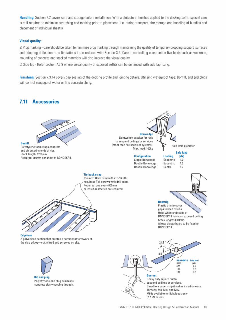
69 LYSAGHT® BONDEK® II Steel Decking Design & Construction Manual
Handling: Section 7.2 covers care and storage before installation. With architectural finishes applied to the decking soffit, special care is still required to minimise scratching and marking prior to placement. (i.e. during transport, site storage and handling of bundles and placement of individual sheets).
Visual quality:
a) Prop marking - Care should be taken to minimise prop marking through maintaining the quality of temporary propping support surfaces and adopting deflection ratio limitations in accordance with Section 3.2. Care in controlling construction live loads such as workman, mounding of concrete and stacked materials will also improve the visual quality.
b) Side lap - Refer section 7.3.9 where visual quality of exposed soffits can be enhanced with side lap fixing.
Finishing: Section 7.3.14 covers gap sealing of the decking profile and jointing details. Utilising waterproof tape, Bonfill, and end plugs will control seepage of water or fine concrete slurry.
BonfillPolystyrene foam stops concreteand air entering ends of ribs.Stock length: 1200mmRequired: 300mm per sheet of BONDEK® ll.
BonstripPlastic trim to covergaps formed by ribs.Used when underside ofBONDEK® ll forms an exposed ceiling.Stock length: 3000mm. Allows plasterboard to be fixed to BONDEK® ll.
EdgeformA galvanised section that creates a permanent formwork atthe slab edges—cut, mitred and screwed on site.
Tie-back strap25mm x 1.0mm fixed with #10-16 x16 hex. head Tek screws with drill point.Required: one every 600mm or less if aesthetics are required.
BonwedgeLightweight bracket for rods
to suspend ceilings or services(other than fire sprinkler systems).
Max. load: 100kg
Rib end plugPolyethylene end plug minimisesconcrete slurry seeping through.
Bon-nutHeavy duty square nut tosuspend ceilings or services.Glued to a paper strip it makes insertion easy.Threads: M8, M10 and M12. M6 is available for light loads only (2.7 kN or less)
Hole 8mm diameter
Safe loadConfiguration Loading (kN)Single Bonwedge Eccentric 1.0Double Bonwedge Eccentric 1.3Double Bonwedge Centra 1.7
BONDEK®ll Safe loadBMT (kN)0.75 4.41.00 6.71.20 6.7
21.5
8.5
7.11 Accessories
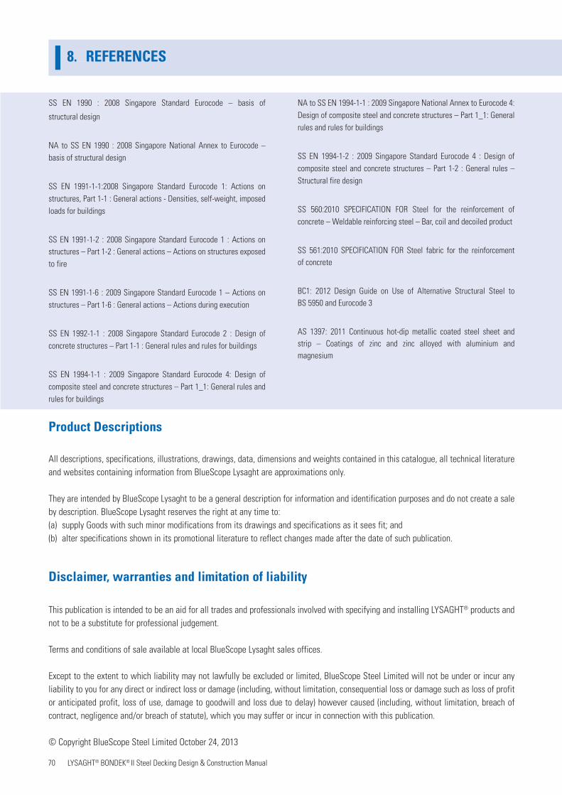
70 LYSAGHT® BONDEK® II Steel Decking Design & Construction Manual
8. REFERENCES8. REFERENCES
SS EN 1990 : 2008 Singapore Standard Eurocode – basis of
structural design
NA to SS EN 1990 : 2008 Singapore National Annex to Eurocode – basis of structural design
SS EN 1991-1-1:2008 Singapore Standard Eurocode 1: Actions on structures, Part 1-1 : General actions - Densities, self-weight, imposed loads for buildings
SS EN 1991-1-2 : 2008 Singapore Standard Eurocode 1 : Actions onstructures – Part 1-2 : General actions – Actions on structures exposed to fire
SS EN 1991-1-6 : 2009 Singapore Standard Eurocode 1 – Actions on structures – Part 1-6 : General actions – Actions during execution
SS EN 1992-1-1 : 2008 Singapore Standard Eurocode 2 : Design of concrete structures – Part 1-1 : General rules and rules for buildings
SS EN 1994-1-1 : 2009 Singapore Standard Eurocode 4: Design of composite steel and concrete structures – Part 1_1: General rules and rules for buildings
NA to SS EN 1994-1-1 : 2009 Singapore National Annex to Eurocode 4: Design of composite steel and concrete structures – Part 1_1: General rules and rules for buildings
SS EN 1994-1-2 : 2009 Singapore Standard Eurocode 4 : Design of composite steel and concrete structures – Part 1-2 : General rules – Structural fire design
SS 560:2010 SPECIFICATION FOR Steel for the reinforcement of concrete – Weldable reinforcing steel – Bar, coil and decoiled product
SS 561:2010 SPECIFICATION FOR Steel fabric for the reinforcementof concrete
BC1: 2012 Design Guide on Use of Alternative Structural Steel toBS 5950 and Eurocode 3
AS 1397: 2011 Continuous hot-dip metallic coated steel sheet andstrip – Coatings of zinc and zinc alloyed with aluminium andmagnesium
Product Descriptions
All descriptions, specifications, illustrations, drawings, data, dimensions and weights contained in this catalogue, all technical literature and websites containing information from BlueScope Lysaght are approximations only.
They are intended by BlueScope Lysaght to be a general description for information and identification purposes and do not create a sale by description. BlueScope Lysaght reserves the right at any time to:(a) supply Goods with such minor modifications from its drawings and specifications as it sees fit; and(b) alter specifications shown in its promotional literature to reflect changes made after the date of such publication.
Disclaimer, warranties and limitation of liability
This publication is intended to be an aid for all trades and professionals involved with specifying and installing LYSAGHT® products and not to be a substitute for professional judgement.
Terms and conditions of sale available at local BlueScope Lysaght sales offices.
Except to the extent to which liability may not lawfully be excluded or limited, BlueScope Steel Limited will not be under or incur any liability to you for any direct or indirect loss or damage (including, without limitation, consequential loss or damage such as loss of profit or anticipated profit, loss of use, damage to goodwill and loss due to delay) however caused (including, without limitation, breach of contract, negligence and/or breach of statute), which you may suffer or incur in connection with this publication.
© Copyright BlueScope Steel Limited October 24, 2013
71 LYSAGHT® BONDEK® II Steel Decking Design & Construction Manual

For technical enquiries:
NS BlueScope Lysaght Singapore Pte Ltd
18 Benoi Sector, Singapore 629851
Tel: (+65) 6264 1577, Fax: (+65) 6265 0951
email: [email protected], web: www.lysaght.com.sg
Please check the latest information which is always available on our website.
Copyright © 2013 by BlueScope Steel Limited. All rights reserved. No part of this brochure shall be reproduced, stored in a retrieval system,
or transmitted in any form or by any means, electronic, mechanical, recording or otherwise, without wrritten permission from BlueScope Steel
Limited. LYSAGHT®, KLIP-LOK®, SPANDEK®, TRIMDEK®, SELECT SEAM®, LOCKED SEAM®, ZIPDEK®, PRESTIGE®, BONDEK®, POWERDEK®,
PROBUILD®, ZINCALUME® and COLORBOND® are registered trademark and ULTRALITETM is a trademark of BlueScope Steel Limited
ABN 16 000 011 058. BlueScope Steel Limited
* Warranty terms and conditions apply.
LYSAGHT®
THERE IS NO EQUIVALENT