Structural Dynamics Branch Research and Accomplishments ... · Structural Dynamics Branch Research...
50
NASA Technical Memorandum 102488 Structural Dynamics Branch Research and Accomplishments for FY 1989 Lewis Research Center Cleveland, Ohio July 1990 N/ A National Aeronautics and Space Adm,n_stratlon Scientific and Technical Information Branch https://ntrs.nasa.gov/search.jsp?R=19900017057 2018-07-15T02:39:22+00:00Z
Transcript of Structural Dynamics Branch Research and Accomplishments ... · Structural Dynamics Branch Research...
NASA Technical Memorandum 102488
Structural Dynamics BranchResearch and Accomplishmentsfor FY 1989
Lewis Research Center
Cleveland, Ohio
July 1990
N/ ANational Aeronautics and
Space Adm,n_stratlon
Scientific and Technical
Information Branch
https://ntrs.nasa.gov/search.jsp?R=19900017057 2018-07-15T02:39:22+00:00Z

Trade names or manufacturers' names are used in this repor_ for Identification
only. Th_s usage does not constitute an official endorsement, either expressed or
lmphed, by the Nanonal Aeronautics and Space Administration
ii
Preface
This document summarizes the technical accomplishments of the Structural DynamicsBranch at the NASA Lewis Research Center for fiscal year 1989. It includes some of thesignificant results of our in-house researchers, contractors, and grantees.
The Structural Dynamics Branch conducts research dealing with advanced propulsion andpower systems as well as precision mechanical systems. Our work directly supportsNASA's turboprop, space experiments, space shuttle main engine, national aerospace plane,supersonic fan, space station, and space power programs. This work can be broadlyclassified into four major activities: turbomachinery aeroelasticity, vibration control,dynamic systems response and analysis, and computational structural methods.
In aeroelasticity, we are developing improved analytical and experimental methods foravoiding flutter and minimizing forced vibration response of aerospace propulsion systems.Work elements include classical (frequency domain) methods, time domain methods,computational methods for fluid-coupled structural response, experimental methods, and
application studies (turboprop, turbofan, turbopump, NAVY cruise missile, and advancedcore technology). This year we will increase our emphasis on the problems associated wiithultra-high-bypass ducted fan aeroelasticity, the aeroelastically forced vibration response ofSSME class turbomachinery blading, NAVY cruise missile propulsion, and counter-rotatingpropfan systems.
In vibration control, we are conceiving, analyzing, developing, and demonstrating newmethods to control vibrations in aerospace systems to increase life and performance. Wc,rkelements include actively controlled structures, passive vibration control methods,computational methods for active vibration control, and application studies - vibrationisolation, piezo-actively and magnetic-controlled bearings, and cryoturbomachinery. Inparticular, magnetic bearing technology continues to be a major focus for us. For thesebearings, methods for unbalance control, critical speed control, and direct control oftransient instabilities in rotating equipment are being developed. New approaches foradaptive real-time digital, analog, and hybrid control strategies for active bearing systems
are also being developed.
In dynamic systems, we are analyzing and verifying the dynamics of interacting systems aswell as developing concepts and methods for motion control in microgravity environs.Work elements include microgravity robotic systems, space mechanisms technology,computational methods for dynamics analysis and application studies - space labmechanisms and robotics, NASP engine sealing concepts, and parallel computing fordynamics analysis. We are currently greatly increasing our emphasis on developing thebasic technology needed for space-based mechanisms in low-earth orbit and high-earth orbitand on lunar and planetary surfaces. Precise, reliable, long-life space-based mechanismscannot be designed with current technology. Thus, methods for designing and forevaluating the design of such mechanisms will be increasingly important. We are
developing technology for reactionless mechanical actuators, precision roller-driven joints forrobot arms and other space-based rotary joints, and high-speed, actively controlled bearingsfor space-based propulsion and pumping systems. We are also developing testing methodsfor evaluating these new technologies.
Com0utational methods development has been included in the three other major focus areaswithin the Structural Dynamics Branch. This work should fundamentally improve the u,mof modern computers for solving realistic structural dynamics problems, with a particularemphasis on parallel processing. In aeroelasticity, computational methods work is focusedon time-domain solutions and coupled fluid structure interaction. In vibration control, the
computational methods are focused on individual bearing control, hierarchical schemes forcontrolling the response of distributed elastic shaft systems, and magnetic vibration isolationof space experiment platforms. In dynamic systems, the focus is on new algorithms forstructural dynamics analysis, robot system control, and modeling of NASP engine seals.
iii

As you will read, we have made some exciting accomplishments in fiscal year 1989. Wehave started some new work and have begun to head in new directions which promise toyield new methods for NASA's missions. Once again, I look forward to next year'saccomplishments and to introducing next year's report.
L.L. KiralyBranch Manager
iv
Contents
Magnetic Suspension Laboratory ............................... 1
Hybrid Controller for Active Vibration Control ....................... 4
Active Control of Rotor Vibrations ............................. 5
Active Control of Flexible Rotor Vibrations by Using Direct Output Feedback ..... 8
Tuned Electromagnetic Damper for Cryogenic Turbopumps ................ 10
Direct Memory Access Data Transfer Interface With a Transputer Board ........ 12
National Aerospace Plane Engine Seal Thermal Analysis atMach 10 Heat Flux Conditions .............................. 13
Effect of Axial Vibration on Helicopter Overrunning Clutches ............... 16
Survey of Requirements for Microgravity-Experiment Mechanisms ............. _8
One-Degree-of-Freedom Reactionless Mechanism ....................... 19
New Results Concerning the Use of Kinematically Redundant Manipulatorsin Microgravity Environments ............................... 21
A Global Approach for Using Kinematic Redundancy to Minimize BaseReactions of Manipulators Used in Microgravity Environments ............. 23
Characterization of Structural Connections by Using Free andForced Response Test Data ................................. 24
Distributed Finite Element Analysis Using a Transputer Network ............ 26
Shape and Topology Optimization by the Homogenization Method ............ 28
Parallel Time Integration of Finite Element Problems ................... 30
Structural Design of a 6-MW Solar Electric Propulsion (SEP) Spacecraftfor Mission to Mars .................................... 32
Solution and Sensitivity Analysis of a Complex TranscendentalEigenproblem With Pairs of Real Eigenvalues ...................... 34
Nonlinear Unsteady Supersonic Axial Flow Aerodynamics ................. 36
Numerical Analysis of Supersonic Flow Through Oscillating CascadeSections by Using a Deforming Grid ........................... 38
Concurrent Processing Adaptation of Aeroelastic Analysis of Propfans .......... 40
Flutter Analysis of Supersonic Throughflow Stator ..................... 41
Appendix - Researchers .................................... 42
Bibliography .......................................... 43
Magnetic Suspension Laboratory
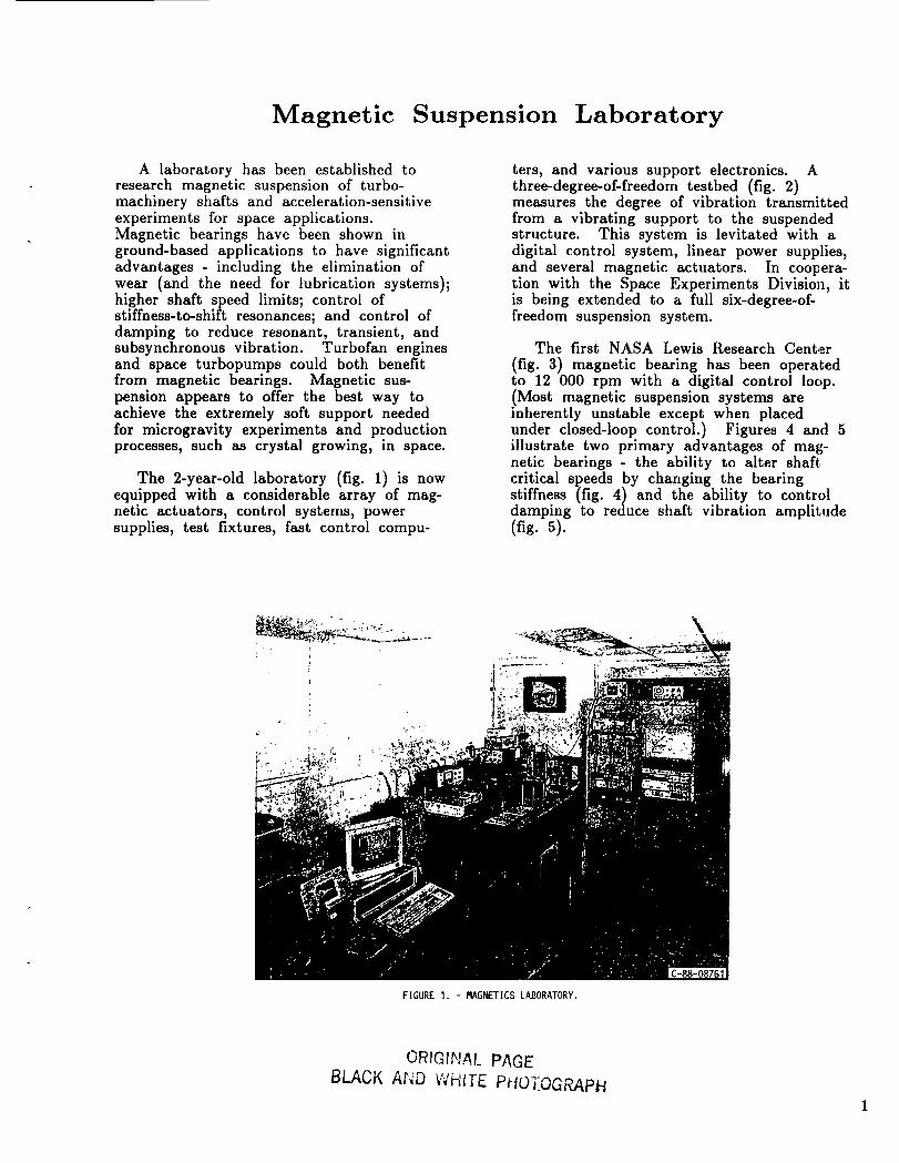
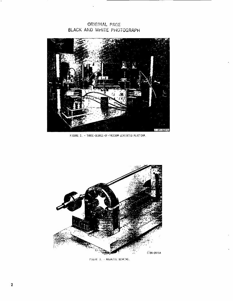
A laboratory has been established toresearch magnetic suspension of turbo-machinery shafts and acceleration-sensitiveexperiments for space applications.Magnetic bearings have been shown inground-based applications to have significantadvantages - including the elimination ofwear (and the need for lubrication systems);higher shaft speed limits; control ofstiffness-to-shift resonances; and control ofdamping to reduce resonant, transient, andsubsynchronous vibration. Turbofan enginesand space turbopumps could both benefitfrom magnetic bearings. Magnetic sus-pension appears to offer the best way toachieve the extremely soft support neededfor microgravity experiments and productionprocesses,such as crystalgrowing, in space.
The 2-year-old laboratory (fig. 1) is nowequipped with a considerable array of mag-netic actuators, control systems, powersupplies, test fixtures, fast control compu-
ters, and various support electronics. Athree-degree-of-freedom testbed (fig. 2)measures the degree of vibration transmittedfrom a vibrating support to the suspendedstructure. This system is levitated with adigital control system, linear power supplies,and several magnetic actuators. In coopera-tion with the Space Experiments Division, itis being extended to a full six-degree-of-freedom suspension system.
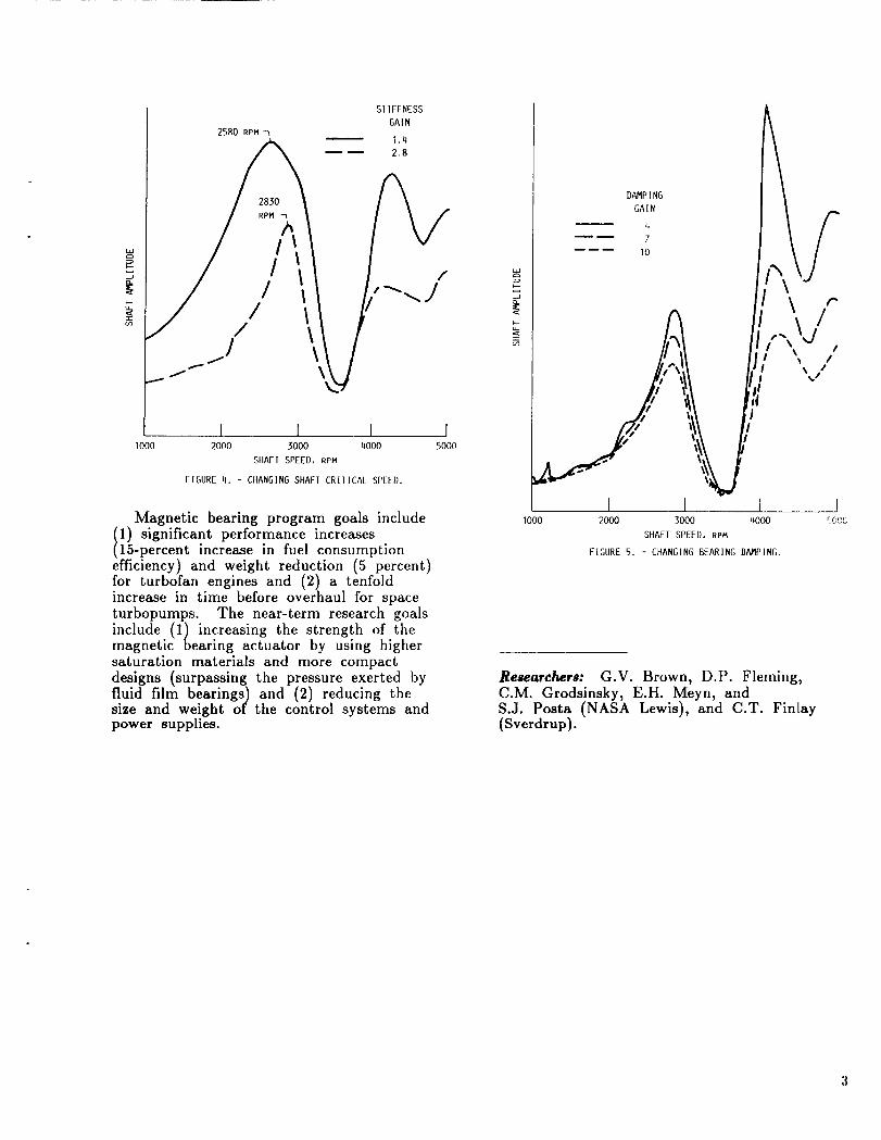
The first NASA Lewis Research Center
(fig. 3) magnetic bearing has been operatedto 12 000 rpm with a digital control loop.(Most magnetic suspension systems areinherently unstable except when placedunder closed-loop control.) Figures 4 and 5illustrate two primary advantages of mag-netic bearings - the ability to alter shaft.critical speeds by changing the bearingstiffness (fig. 4) and the ability to controldamping to reduce shaft vibration amplitude(fig. 5).
\
FIGURE 1. - MAGNETICS LABORATORY.
ORIGINAL PAGE
BLACK AND WHITE PHOTOGRAPH
ORIG;F_,_L PAG,-
BLACK AND WHITE PHOTOGRAPH
o
FIGURE 2. - TIIREE-DEGREE-OF-FREEDOM LEVITATED PLATFORM.
FIGURE $. -- MAGNETIC BEARING
I000
2580 RPM
S1 IFFNESS
GAIN
1.4
2.8
2830
RPM
lI
//
/ \1 \
J
\
I I I2000 3000 qO00
SIIAFI SPEED, RPM
FIGURE l). - CIIANGING SHAFI CRIIICAL SPEED.
I5000
Magnetic bearing program goals include
1) significant performance increases15-percent increase in fuel consumption
efficiency) and weight reduction (5 percent)for turbofan engines and (2) a tenfoldincrease in time before overhaul for spaceturbopumps. The near-term research goals
include (1) increasing the strength of themagnetic bearing actuator by using highersaturation materials and more compact
designs (surpassing the pressure exerted byfluid film bearings) and (2) reducing thesize and weight of the control systems andpower supplies.
d
_o
DAMPING
GAIN
4
7
10
\ ¢"
!
I I i _JI000 2000 3000 4000 CGCC
SHAFT SPEED, RPM
FIGURE 5. - CHANGING BEARING DAMPING.
Researchers: G.V. Brown, D.P. Fleming,C.M. Grodsinsky, E.H. Meyn, andS.J. Posta (NASA Lewis), and C.T. Finlay(Sverdrup).
Hybrid Controller for Active Vibration Control
A unique controller was recentlydeveloped by the Technical University ofMunich, Institute of Mechanics, for systemsrequiring active vibration control. Thecontroller employs 12-bit digital-to-analog(D/A) converters (DAC's) that are capableof full four-quadrant multiplication. Theanalog output signal from these DAC's isderived from a conventional R-2R current-switching ladder network, and this signal isdirectly proportional to the product of theapplied reference voltage and a digital inputword. If an analog signal anywhere in therange from -10 to 10 V is applied to thereference voltage terminals and the value ofthe digital input is in the range of-1 to 1,the output signal can have any value from-10 to 10 V. Thus each DAC acts as a
digitally controlled attenuator since theanalog output amplitude is dependent on thevalue of the digital input word. The con-troller is classified as a hybrid because itsoutput responds to both analog and digitalinputs.
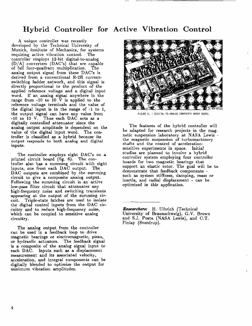
The controller employs eight DAC's on aprinted circuit board (fig. 6). The con-troller also has a summing circuit with eightinputs, one from each DAC output. TheDAC outputs are combined by the summingcircuit to give a composite analog output.Following the summing circuit is an activelow-pass filter circuit that attenuates anyhigh-frequency noise and switching transientsappearing at the output of the summing cir-cuit. Triple-state latches are used to isolatethe digital control inputs from the DAC cir-cuitry and to reduce high-frequency noise,which can be coupled to sensitive analogcircuitry.
The analog output from the controllercan be used in a feedback loop to drivemagnetic bearings or electromagnetic, piezo,or hydraulic actuators. The feedback signalis a composite of the analog signal input toeach DAC. Inputs such as a displacementmeasurement and its associated velocity,acceleration, and integral components can bedigitally blended to optimize the output forminimum vibration amplitudes.
FIGURE G. - DIGITAL-TO-ANALOG CONVERTER ARRAY BOARD.
The features of the hybrid controller willbe adapted for research projects in the mag-netic suspension laboratory at NASA Lewis -the magnetic suspension of turbomachineryshafts and the control of acceleration-sensitive experiments in space. Initialstudies are planned to involve a hybridcontroller system employing four controllerboards for two magnetic bearings thatsupport an elastic rotor. The goal will be todemonstrate that feedback components -such as system stiffness, damping, mass orinertia, and radial displacement - can beoptimized in this application.
Researchers: H. Ulbrich (TechnicalUniversity of Braunschweig), G.V. Brownand S.J. Posta (NASA Lewis), and C.T.Finlay (Sverdrup).
Active Control of Rotor Vibrations
Currently, jet engine shaft vibrations aresuppressed by passive devices such assqueeze film dampers. Research is beingperformed to replace or supplement thesewith active dampers to reduce engine weightand produce more predictable and reliabledamping. Piezoelectric pushers are used asactuators in these active dampers because oftheir light weight, compactness, and lowvoltage.
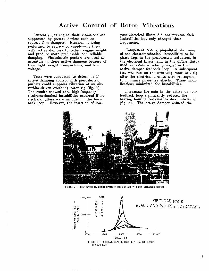
Tests were conducted to determine if
active damping control with piezoelectricpushers could suppress vibration of an air-turbine-driven overhung rotor rig (fig. 7).The results showed that high-frequencyelectromechanical instabilities occurred if noelectrical filters were included in the feed-
back loop. However, the insertion of low-
pass electrical filters did not prevent theirinstabilities but only changed theirfrequencies.
Component testing pinpointed the causeof the electromechanical instabilities to bephase lags in the piezoelectric actuators, inthe electrical filters, and in the different!iatorused to obtain a velocity signal in theactive damper feedback loop. A subsequenttest was run on the overhang rotor test rigafter the electrical circuits were redesignedto minimize phase lag effects. These modi-fications minimized the instabilities.
Increasing the gain in the active damperfeedback loop significantly reduced thebearing housing response to disk unbalance(fig. 8). The active damper reduced the
FIGURE 7. - HIGH-SPEED TRANSIENT DYNN_ICS RIG FOR ACTIVE ROTORVIBRATION CONTROL.
.OSO --
g
02000
GAIN
0 o
[] I
5
ORT_ TNL_d2PAOEi. LACF, '"' "" .... ,--,........
C'°
20
4000 GO00 8000 10 000
SPEED, RPM
FIGURE 8. - OUTBOARD BEARING HOUSING VIBRATION VERSUS
FEEDBACK GAIN.
5
0
w
_-- _.]
.......^^ AAAAAAAAAA ., v-v vvvvvvvvvvvvv
I I I I I
F...... AAAAAAAAAAAAAAAA'".... "vvvvvvvvvvvvvvvk
.04 .08 .12 .18 .20 0
lIME, sec
(a) NO C0NIROL. (b) Wllll CONIROI
I I I I I,04 .08 .12 .16 .20
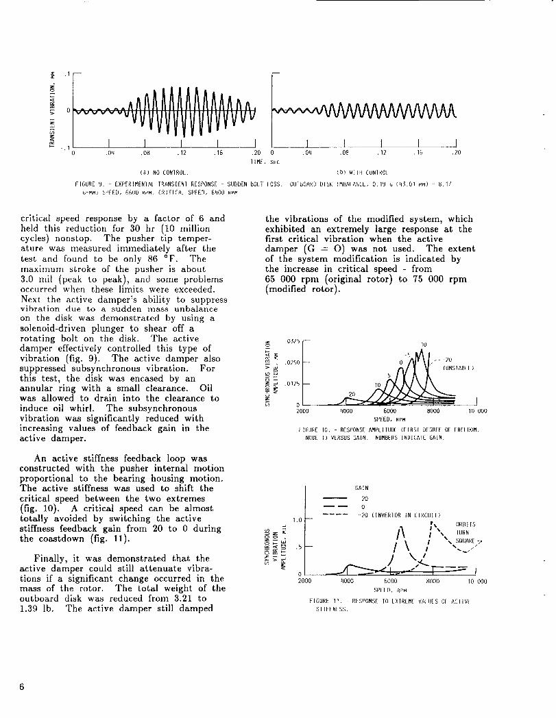
FIGURE 9. - EXPERIMEN1AL TRANSIENI RESPONSE - SUDDEN BOLT LOSS. OIJII_OARI) DISK IMBAIANCL, 0.19 _ (45.01 MM) - 8.17
G-MM; SPFE{), GGO0 Ri'M. CRITICAl SPFEO, 61100 RPM
critical speed response by a factor of 6 andheld this reduction for 30 hr (10 millioncycles) nonstop. The pusher tip temper-ature was measured immediately after thetest and found to be only 86 °F. Themaximum stroke of the pusher is about
3.0 rail (peak to peak), and some problemsoccurred when these limits were exceeded.
Next the active damper's ability to suppressvibration due to a sudden mass unbalance
on the disk was demonstrated by using asolenoid-driven plunger to shear off a
rotating bolt on the disk. The activedamper effectively controlled this type ofvibration (fig. 9). The active damper alsosuppressed subsynchronous vibration. For
this test, the disk was encased by anannular ring with a small clearance. Oilwas allowed to drain into the clearance to
induce oil whirl. The subsynchronous
vibration was significantly reduced withincreasing values of feedback gain in theactive damper.
An active stiffness feedback loop wasconstructed with the pusher internal motionproportional to the bearing housing motion.The active stiffness was used to shift the
critical speed between the two extremes(fig. 10). A critical speed can be almosttotally avoided by switching the activestiffness feedback gain from 20 to 0 during
the coastdown (fig. 11).
Finally, it was demonstrated that theactive damper could still attenuate vibra-tions if a significant change occurred in themass of the rotor. The total weight of theoutboard disk was reduced from 3.21 to
1.39 lb. The active damper still damped
the vibrations of the modified system, which
exhibited an extremely large response at thefirst critical vibration when the active
damper (G = O) was not used. The extentof the system modification is indicated bythe increase in critical speed - from
65 000 rpm (original rotor) to 75 000 rpm(modified rotor).
0375
_ .0750 [
o .o12sI--
2000
I0
0-5/_I,F-20
4000 GO00 8000 10 000
SPEED, RPM
tlGURE 10. - RESPONSE /_IPLIIUI)L (FIRSI DEGREE OF FREII)OM,
NODE 1) VERSUS GAIN. NUMBERS ]NIHCAIE GAIN.
2o
1.0
.5
0
2000
GAIN
2O
0
-20 (INVERIOR IN CIRCUII)
/1 I,, OR. ,s{ .,,. IURN
l _,,JQUARE 7/\ , ../j ',/.
4000 6000 8000 I0 000
SPEED, RPM
FIGURE II. - RESPONSE 10 LXIREME VALUES Ol ACIIV(
SEIFFNLSS.
Future plans for the project include thefollowing:
(l) Working with the piezoelectricpusher manufacturer to develophigh-temperature actuators withincreased stroke and force, anddecreased phase lag and voltage
(2) Testing piezoelectric actuatorcomponents to determine how theirphase lag varies with their struc-tural and electrical characteristics
(3) Designing special pusher bracketsand pushers to avoid instability
(4) Determining T700 engine appli-cations for the piezoelectric actuatorspecifications-based active damper//spring
(5) Performing simulations todetermine if control algorithms thatuse linear combinations of active
stiffness and damping can reducevibration sufficiently with smallerstroke requirements than uncoupledactive dampers or stiffnesses
(6) Developing modal identificationalgorithms that use piezoelectricpushers to obtain the modal char-acteristics of the rotor-bearingsystem
Researchers: A.F. Kascak (AVSCOM),A.B. Palazzolo and R.R. Lin (Texas A&M),G.T. Montague (Sverdrup), and
J.J. Ropchock and T.F. Lakatos (NASALewis).
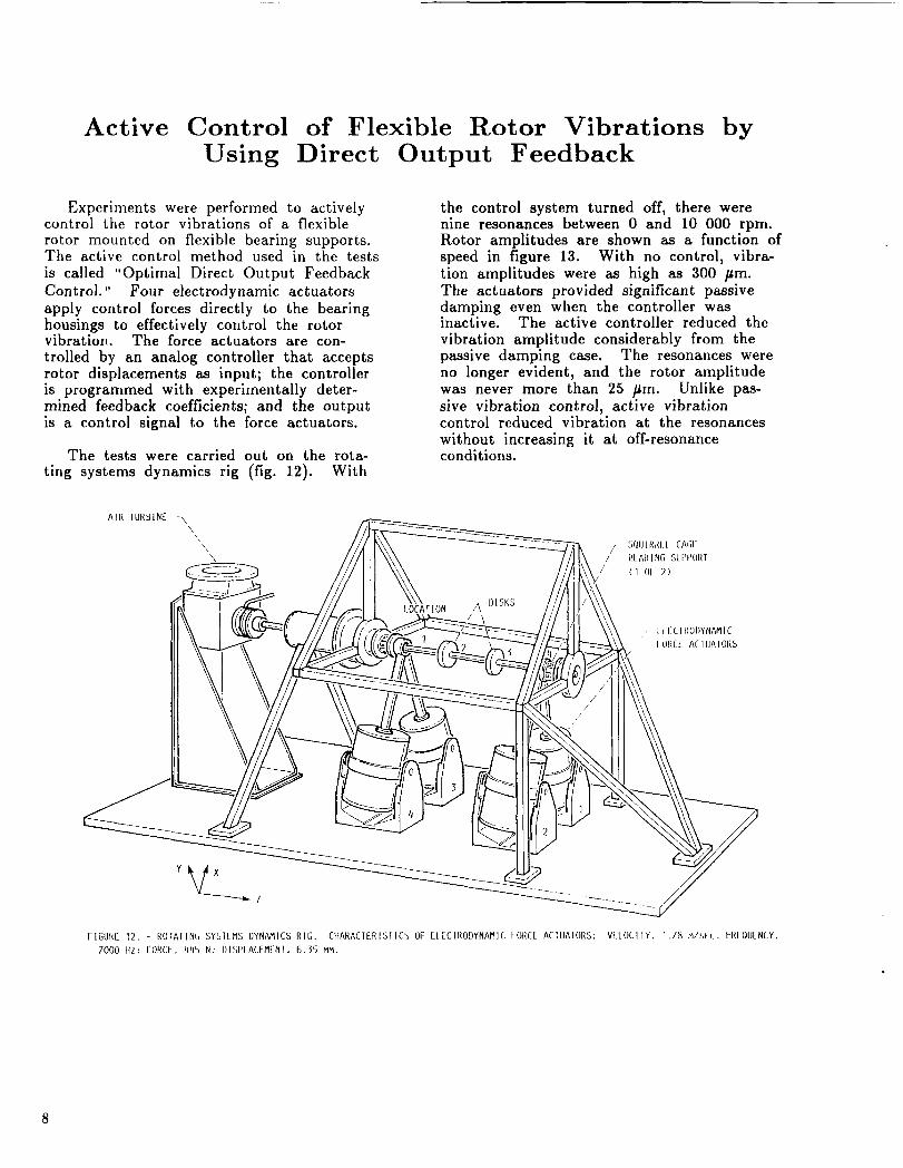
Active Control of Flexible Rotor Vibrations byUsing Direct Output Feedback
Experiments were performed to activelycontrol the rotor vibrations of a flexible
rotor mounted on flexible bearing supports.The active control method used in the tests
is called "Optimal Direct Output Feedback
Control." Four electrodynamic actuators
apply control forces directly to the bearinghousings to effectively control the rotorvibration. The force actuators are con-
trolled by an analog controller that acceptsrotor displacements as input; the controlleris programmed with experimentally deter-mined feedback coefficients; and the outputis a control signal to the force actuators.
The tests were carried out on the rota-
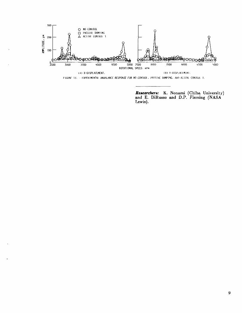
ting systems dynamics rig (fig. 12). With
the control system turned off, there werenine resonances between 0 and 10 000 rpm.Rotor amplitudes are shown as a function ofspeed in figure 13. With no control, vibra-
tion amplitudes were as high as 300 /_m.The actuators provided significant passivedamping even when the controller wasinactive. The active controller reduced the
vibration amplitude considerably from thepassive damping case. The resonances wereno longer evident, and the rotor amplitude
was never more than 25 /_m. Unlike pas-sive vibration control, active vibrationcontrol reduced vibration at the resonances
without increasing it at off-resonanceconditions.
AIR TURBINE -\\
\\
\
LOCATION A -DISKS
\
/ SQUIRRL[ CAGI-/ I_LARING SUPPORt
/ ( 10l ? )
II IlL IROI)YNAMIC
IORCL AfIIJAIONS
FIGURE 12. - ROIAIINb SYSILI'IS DYNANICS RIG. CIIARACIERISIICS OF E[ECIRODYNANIC IORC[ MIUAIORS: VLLOCIIY, 1./8 M/SlC, I-RLQUENCY.
7000 llZ: FORCF, 445 N; DISP[ACEMENI, 6.35 MM.
3o0[--m o No CONTROL
loo_
0 i t i t a tld
2500 3000 3500 4000 4500 5000 2500 3000 5500 riO00 4500 5000
ROTATIONAL SPEED, RPM
(a) X-DISPLACEMENI. (b) Y-DISPIACEMLNi.
FIGURE 15. - EXPERIMENTAL UNI_ALANCE RESPONSE FOR NO CONIROI, PASSIVE I)AMPtNG, ANI_ ACIIVE CONTROL I.
Researchers: K. Nonami (Chiba University)and E. DiRusso and D.P. Fleming (NASALewis).
Tuned Electromagnetic Damper for CryogenicTurbopumps
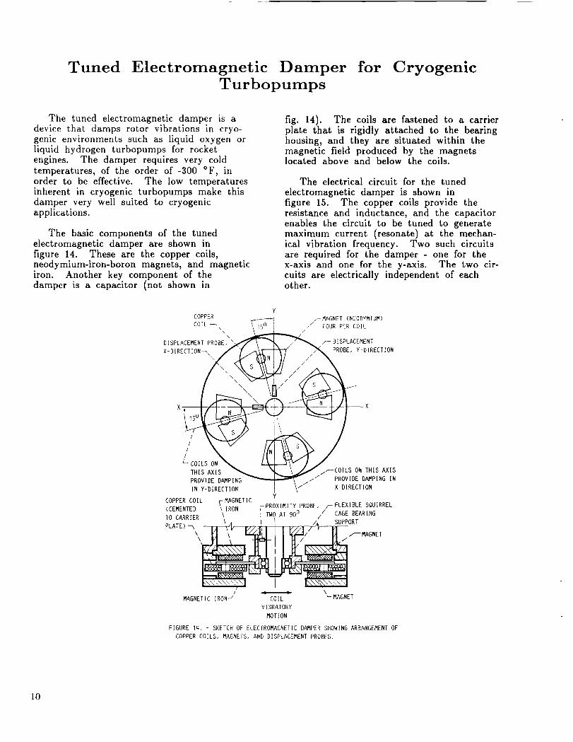
The tuned electromagnetic damper is adevice that damps rotor vibrations in cryo-genic environments such as liquid oxygen orliquid hydrogen turbopumps for rocketengines. The damper requires very coldtemperatures, of the order of -300 °F, in
order to be effective. The low temperaturesinherent in cryogenic turbopumps make thisdamper very well suited to cryogenicapplications.
The basic components of the tunedelectromagnetic damper are shown infigure 14. These are the copper coils,neodymium-iron-boron magnets, and magneticiron. Another key component of thedamper is a capacitor (not shown in
fig. 14). The coils are fastened to a carrierplate that is rigidly attached to the bearinghousing, and they are situated within themagnetic field produced by the magnetslocated above and below the coils.
The electrical circuit for the tuned
electromagnetic damper is shown in
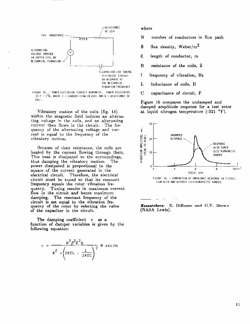
figure 15. The copper coils provide theresistance and inductance, and the capacitorenables the circuit to be tuned to generatemaximum current (resonate) at the mechan-ical vibration frequency. Two such circuitsare required for the damper - one for thex-axis and one for the y-axis. The two cir-cuits are electrically independent of eachother.
Y
COPPER _I F_GNET (NEODYMIUM)
COIL _\ \15 0 [ z / FOUR PER COIL
\\ _////
DISPLACEMENT PROBE, _ _ _ /_ _DISPLACEMENT
,,'coi s \ / iTHIS AXIS _ _ _ \_ /_COILS ON THIS _IS
PROV_E D_ING _ "_ ,// PROVIDE D_PING IN
'_'ION" \i X-DIRECTION
Y
COPPER COIL F MAGNETIC(CEMENTED \ IRON FPROXIMITY PROBE, _FLEXIBLE SQUIRREL
70 CARRIER \\
PLATE) "-,,\
MAGNETIC IRON-'
11TW_AI 900 ii CAG/ASUP_o_ARING
PMA NET
CO IL _ MAGNET
V IBRATORY
MOTION
FIGURE 14. - SKETCH OF ELECTROMAGNETIC DAMPER SHOWING ARRANGEMENT OF
COPPER COILS, MAGNEFS, AND DISPLACEMENT PROBES.
lO
rRESIS1ANCE
/ OF COIL
i ICOIL INDUCTANCE ....
AIIERNAIING
VOLTAGE INDUCED
IN COPPER COIL BY /MECIIANICAL VIBRATION -/
I
Z-CAPACITOR _OR IUN[NG
ELECIRICAL CIRCUIT
TO RESONAIE AT
THE MECHANICAL
VIBRATION FREOUFNCY
FIGURE 15. - TUNED ELECIRICAL CIRCUI[ SCHEMATIC. POWER DISSIPAIEI)
IS P : 12R, WHERE I : CURRENT FLOW IN COIL AND R = RESISIANCE OF
COIL.
Vibratory motion of the coils (fig. 14)within the magnetic field induces an alterna-ting voltage in the coils, and an alternatingcurrent then flows in the circuit. The fre-
quency of the alternating voltage and cur-rent is equal to the frequency of thevibratory motion.
Because of their resistance, the coils are
heated by the current flowing through them.This heat is dissipated to the surroundings,thus damping the vibratory motion. Thepower dissipated is proportional to thesquare of the current generated in theelectrical circuit. Therefore, the electricalcircuit must be tuned so that its resonant
frequency equals the rotor vibration fre-quency. Tuning results in maximum currentflow in the circuit and hence maximum
damping. The resonant frequency of thecircuit is set equal to the vibration fre-quency of the rotor by selecting the valueof the capacitor in the circuit.
The damping coefficient c as afunction of damper variables is given by the
following equation:
where
N number of conductors in flux path
B flux density, Weber/m 2
g length of conductor, m
R resistance of the coils, Q
f frequency of vibration, Hz
L inductance of coils, H
C capacitance of circuit, F
Figure 16 compares the undamped anddamped amplitude response for a test rotor
at liquid nitrogen temperature (-321 °F).
30
J
20do
o _ 10
UNDAMPED#k
RESPONSEs\\ I_
"I _ _RESPONSE
I.'_. "" wlr._UNED_ y \- ELEC ROM GNE ,
4 6 8 IOxY b5
SPEED, RPM
FIGURE 16. - COMPARISON OF UNBALANCE RESPONSE IN Y-I)IR_C-
TION WIlll AND WITIIOUr EI_ECIROMAGNEIIC DAMPER.
Researchers: E. DiRusso and G.V. Brown
(NASA Lewis).
N2fl2p2Rc - N sec/m
(2 frfL 1) 2R2 + - 2_fC
II
Direct Memory Access Data Transfer Interface
With a Transputer Board
An IBM PC-AT based interface to an
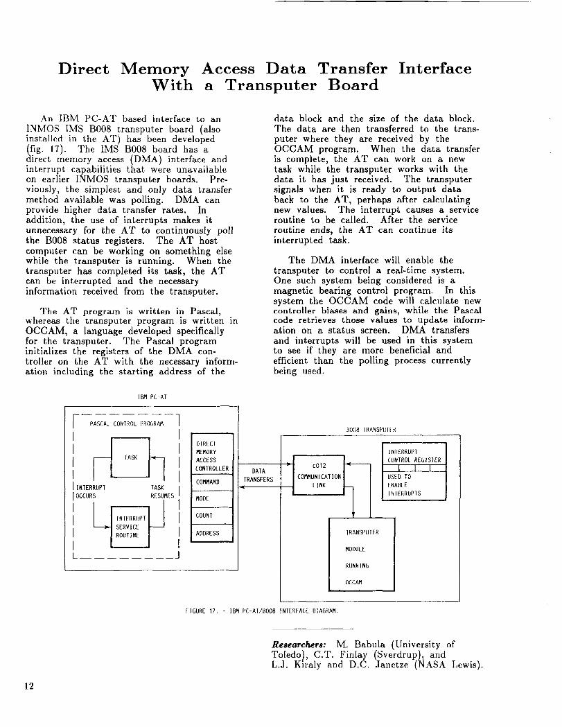
INMOS IMS B008 transputer board (alsoinstalled in the AT) has been developed(fig. 17). The IMS B008 board has adirect memory access (DMA) interface andinterrupt capabilities that were unavailableon earlier INMOS transputer boards. Pre-viously, the simplest and only data transfermethod available was polling. DMA canprovide higher data transfer rates. Inaddition, the use of interrupts makes itunnecessary for the AT to continuously pollthe B008 status registers. The AT host
computer can be working on something elsewhile the transputer is running. When thetransputer has completed its task, the ATcan be interrupted and the necessaryinformation received from the transputer.
The AT program is written in Pascal,whereas the transputer program is written in
OCCAM, a language developed specificallyfor the transputer. The Pascal programinitializes the registers of the DMA con-troller on the AT with the necessary inform-ation including the starting address of the
data block and the size of the data block.The data are then transferred to the trans-
puter where they are received by theOCCAM program. When the data transferis complete, the AT can work on a newtask while the transputer works with thedata it has just received. The transputersignals when it is ready to output databack to the AT, perhaps after calculatingnew values. The interrupt causes a serviceroutine to be called. After the service
routine ends, the AT can continue itsinterrupted task.
The DMA interface will enable the
transputer to control a real-time system.One such system being considered is amagnetic bearing control program. In thissystem the OCCAM code will calculate newcontroller biases and gains, while the Pascalcode retrieves those values to update inform-ation on a status screen. DMA transfers
and interrupts will be used in this systemto see if they are more beneficial andefficient than the polling process currentlybeing used.
IBM PC-AT
PASCAL CONTROL PROGRAM
I
I tASK
I INTERRUPT TASK
I OCCURS RESUMES
II I IINTERRUPTI I
service
It
DIRECT
MEMORY
ACCESS
CONTROLLER
COMMAND
MODE
COUNI
ADDRESS
DATA I _ I c012TRANSFERS COMMUNICATION
LINK
BOO8 IRANSPUIER
INIERRUP!
| CONTROL REGISIER
I l i lI USED TO
I ENABLE
I INTERRUPIS I
IRANSPUTER
MODULE
RUNNING
OCCAM
FIGURE 17. - IBM PC-ATIBO08 INTERFACE DIAGRAM.
Researchers: M. Babula (University of
Toledo), C.T. Finlay (Sverdrup), andL.J. Kiraly and D.C. Janetze (NASA Lewis).
12
National Aerospace Plane Engine Seal ThermalAnalysis at Mach 10 Heat Flux Conditions
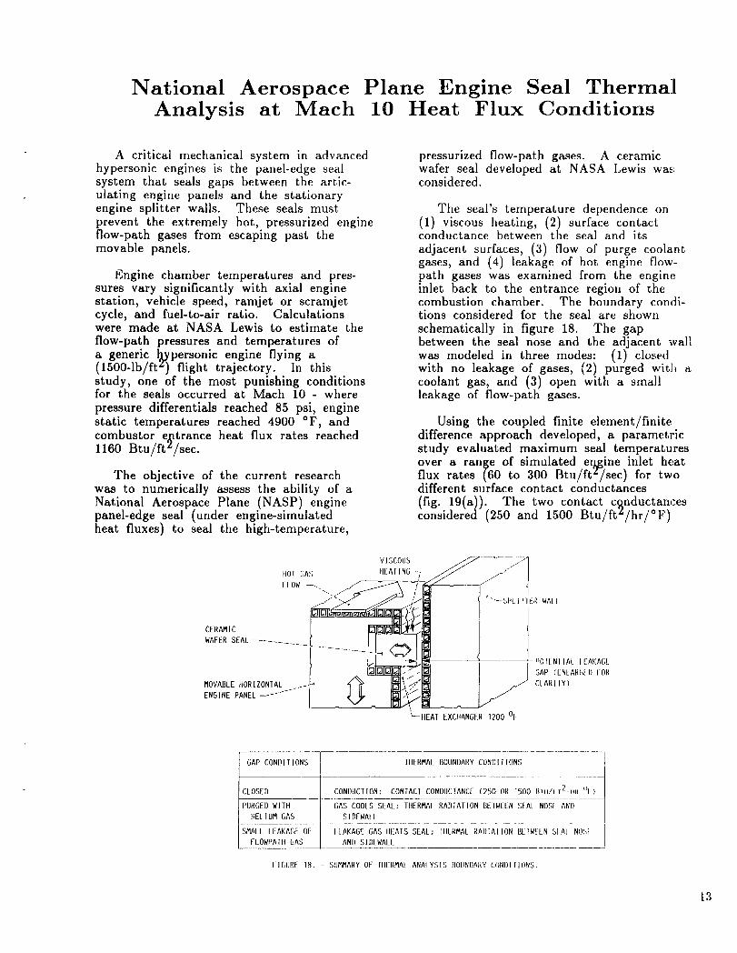
A critical mechanical system in advancedhypersonic engines is the panel-edge sealsystem that seals gaps between the artic-ulating engine panels and the stationaryengine splitter walls. These seals must
prevent the extremely hot, pressurized engineflow-path gases from escaping past themovable panels.
Engine chamber temperatures and pres-sures vary significantly with axial enginestation, vehicle speed, ramjet or scramjetcycle, and fuel-to-air ratio. Calculationswere made at NASA Lewis to estimate the
flow-path pressures and temperatures ofa generic llypersonic engine flying a(1500-1b/ft z) flight trajectory. In thisstudy, one of the most punishing conditionsfor the seals occurred at Maeh 10 - where
pressure differentials reached 85 psi, engine
static temperatures reached 4900 °F, andcombustor e_atrance heat flux rates reached
1160 Btu/ftL/sec.
The objective of the current researchwas to numerically assess the ability of a
National Aerospace Plane (NASP) enginepanel-edge seal (under engine-simulatedheat fluxes) to seal the high-temperature,
pressurized flow-path gases. A ceramicwafer seal developed at NASA Lewis was:considered.
The seal's temperature dependence on(1) viscous heating, (2) surface contactconductance between the seal and its
adjacent surfaces, (3) flow of purge coolantgases, and (4) leakage of hot engine flow-path gases was examined from the engine
inlet back to the entrance region of thecombustion chamber. The boundary condi-tions considered for the seal are shown
schematically in figure 18. The gapbetween the seal nose and the adjacent wallwas modeled in three modes: (1) closedwith no leakage of gases, (2) purged with acoolant gas, and (3) open with a sma]lleakage of flow-path gases.
Using the coupled finite element/finitedifference approach developed, a parametricstudy evaluated maximum seal temperatures
over a range of simulated erhgine inlet heatflux rates (60 to 300 Btu/ftZ/sec) for twodifferent surface contact conductances
(fig. 19(a)). The two contact c_nductancesconsidered (250 and 1500 Btu/ft'/hr/°F)
HOl GAS HEALING
-SL ..... [ //
CLARI iY)
ENGINE PANEL ....... I \. I"_I:--
L
_IIEAT EXCIIANGER 1200 °F
GAP CONDI [ I ONS TIIERNAI_ BOUNDARY CON[)I 110NS
CLOSED CONDUCTION: CONTACI CONDUCTANCE (250 OR lSO0 BTu/f f2-Hr °l)
PURGED WITtt
HELIUM GAS
SNALL LEAKAGE OF
f-I_OWPAIII GAS
GAS COOLS SEAL; TIIERMAI RADIATION BEIWEEN SEAL NOSE AND
SIDEWALL
lEAKAGE GAS IIEAIS SEAL; IIIERNAL RA])IAIION BEIWELN SIAl NOSI
AND SIDEWALL
FIGURE 18. - SUM/_ARY OF TIIERNAL ANALYSIS BOUNI)AI{Y LONI)IIIONS.
13
2500
2o00 -
_ 1500 --
lO000
0
[]
CONTACT
CONDUCTANCE,
BtU/FT2-Hr OF
250
1500
GAP CONDITION
NO COOLANT; GAP CLOSED
He COOLED_ GAP, 0.0007 In.
I I I I]00 200 300 400
IIFAT FLUX, BtU/FT2-SEC
(a) MA×IMUM SEAl. IEMPERATURE FOR ENGINE INLE] IlEAl
FlUX RA]ES FOR 1WO SURFACE CON1ACT CONDUCIANC[S.
GAP CIOSI21)
4500 --
4000
3500
&
_ 3o0o --
E
_ 2500 --
2000 --
1500 --
800
I
1 I 1 J900 1000 1100 1200
ItLAI FI UX, BltJ/f-tP-bf_C
(b) MAXIMUM SIAl IEMPLRAIURE IOR COMBUSIOI_ LNTI,ANCL
REGION HEAr FLIIX RAILS !=OR IWO SIIRIA([ CONIAII
CONDUCIANCES CASE 1. GAP EtOS[IL NO CO01ANI,
CASE 2: SI"IAII hAl}, lie PURGE CO01ANI.
FIGURE 19. - MAXIMUM CERAMIC WAFER SLA[ TEMPLRAIURL I OR ENGIN[ INLLI AND COMBUSIOR [NIRANCE RI{.ION IIt AI I IUX RAIES
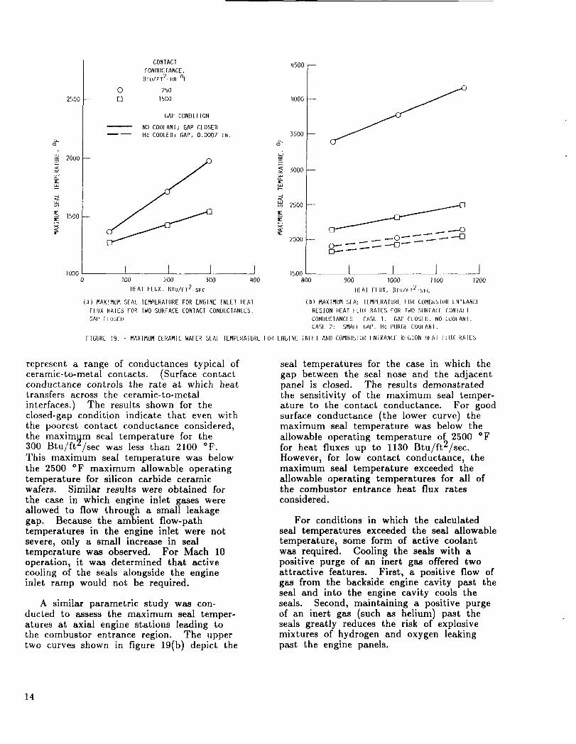
represent a range of conductances typical ofceramic-to-metal contacts. (Surface contactconductance controls the rate at which heattransfers across the ceramic-to-metal
interfaces.) The results shown for theclosed-gap condition indicate that even withthe poorest contact conductance considered,
the maximNm seal temperature for the300 Btu/ft:/sec was less than 2100 °F.This maximum seal temperature was below
the 2500 °F maximum allowable operatingtemperature for silicon carbide ceramicwafers. Similar results were obtained for
the case in which engine inlet gases wereallowed to flow through a small leakagegap. Because the ambient flow-pathtemperatures in the engine inlet were notsevere, only a small increase in sealtemperature was observed. For Mach 10operation, it was determined that activecooling of the seals alongside the engineinlet ramp would not be required.
A similar parametric study was con-ducted to assess the maximum seal temper-atures at axial engine stations leading tothe combustor entrance region. The uppertwo curves shown in figure 19(b) depict the
seal temperatures for the case in which thegap between the seal nose and the adjacentpanel is closed. The results demonstratedthe sensitivity of the maximum seal temper-ature to the contact conductance. For good
surface conductance (the lower curve) themaximum seal temperature was below the
allowable operating temperature of 2500 °Ffor heat fluxes up to 1130 Btu/ft2/sec.However, for low contact conductance, themaximum seal temperature exceeded theallowable operating temperatures for all ofthe combustor entrance heat flux ratesconsidered.
For conditions in which the calculated
seal temperatures exceeded the seal allowabletemperature, some form of active coolantwas required. Cooling the seals with apositive purge of an inert gas offered twoattractive features. First, a positive flow ofgas from the backside engine cavity past theseal and into the engine cavity cools theseals. Second, maintaining a positive purge
of an inert gas (such as helium) past theseals greatly reduces the risk of explosivemixtures of hydrogen and oxygen leakingpast the engine panels.
14
The seal temperatures of the lower twocurves of figure 19(b) are calculated with asmall flow rate of 70 °F helium, 15 psiabove local engine flowpath pressure flowingfrom the backside of the seal past the sealnose into the engine flowpath. As can beseen in the figure, the maximum temper-ature of the seal was lowered to below the2500 °F over the wide heat flux rangeconsidered. The purge coolant effects onthe hot seal were determined with a
specially developed one-dimensional, com-pressible flow code that accounted for theeffects of heat transfer, friction, and variable
gas properties. The LEAK finite differencecode was run iteratively with MARC (ageneral purpose finite element code) topredict temperature distributions within theseal. The solution converged to the firtalseal temperatures when the seal boundaryand leakage gas were in thermal equilibrium.
Researchers: B.M. Steinetz (NASA Lewis),M. Tong (Sverdrup), and W.J. Coirier(NASA Lewis).
_5
Effect of Axial Vibration on HelicopterOverrunning Clutches
A sprag overrunning clutch is an integralpart of a helicopter's drive train. Ittransmits torque from the engine to thecombining gearbox and overruns when the
gearbox rotates faster than the engine.Sprag clutches operate on the wedgingaction of a small sprag located between theinner and outer race. Engagement occurswhen relative motion between the two races
forces the camlike sprag to a more uprightposition. Many clutch engagement failureshave occurred while the second turbine was
being brought on-line under vibratoryconditions. Tests were conducted to
determine the axial vibratory load which
would induce slippage in an engaged clutch.
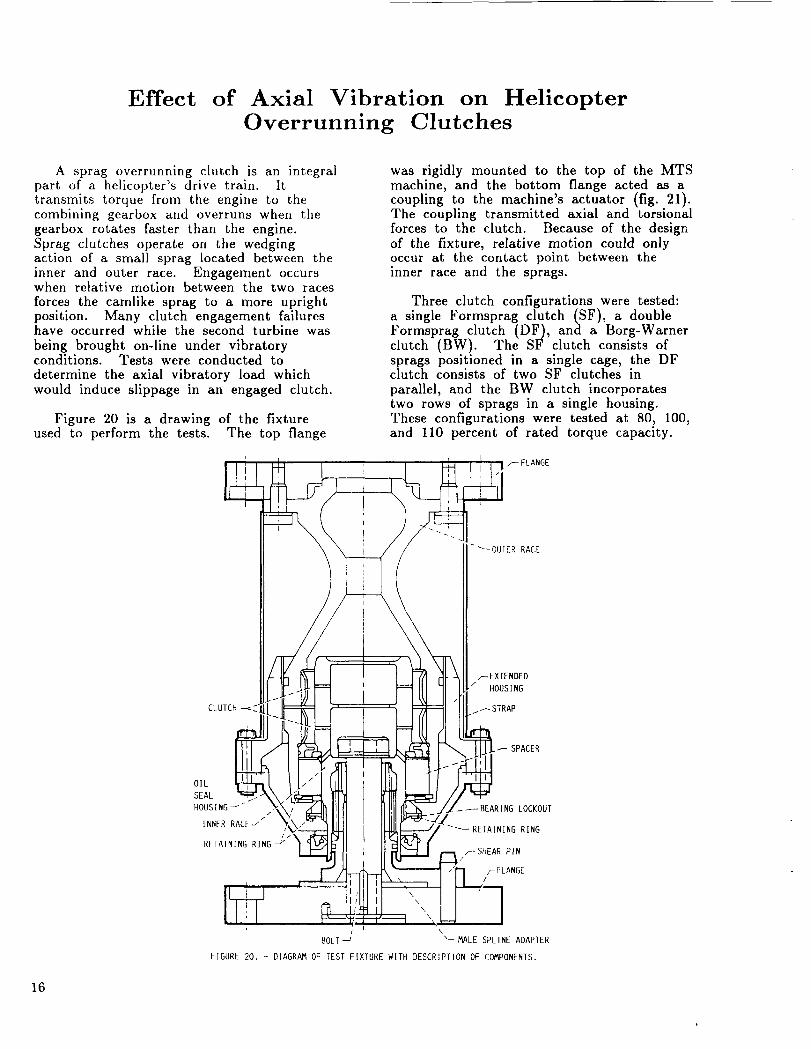
Figure 20 is a drawing of the fixtureused to perform the tests. The top flange
was rigidly mounted to the top of the MTSmachine, and the bottom flange acted as acoupling to the machine's actuator (fig. 21).The coupling transmitted axial and torsionalforces to the clutch. Because of the designof the fixture, relative motion could onlyoccur at the contact point between theinner race and the sprags.
Three clutch configurations were tested:a single Formsprag clutch (SF), a doubleFormsprag clutch (DF), and a Borg-Warnerclutch (BW). The SF clutch consists ofsprags positioned in a single cage, the DFclutch consists of two SF clutches in
parallel, and the BW clutch incorporatestwo rows of sprags in a single housing.These configurations were tested at 80, 100,and 110 percent of rated torque capacity.
ANGE
.--EXTENDED
HOUSING
I_STRAP
SPACER
OIL
SEAL
HOUSING J_/
/INNER RACE--"
RETAINING RING j
•_BEARING LOCKOUT
-_RETAINING RING
r SHEAR PIN
/
BOLT "-MALE SPLINE ADAPTER
FIGURE 20. - DIAGRAM OF [EST FIXTURE WITH DESCRIPTION OF COMPONENTS.
16
OR;GINAL PAGE
BLACK AND WHITE ptdOTOGRAPH
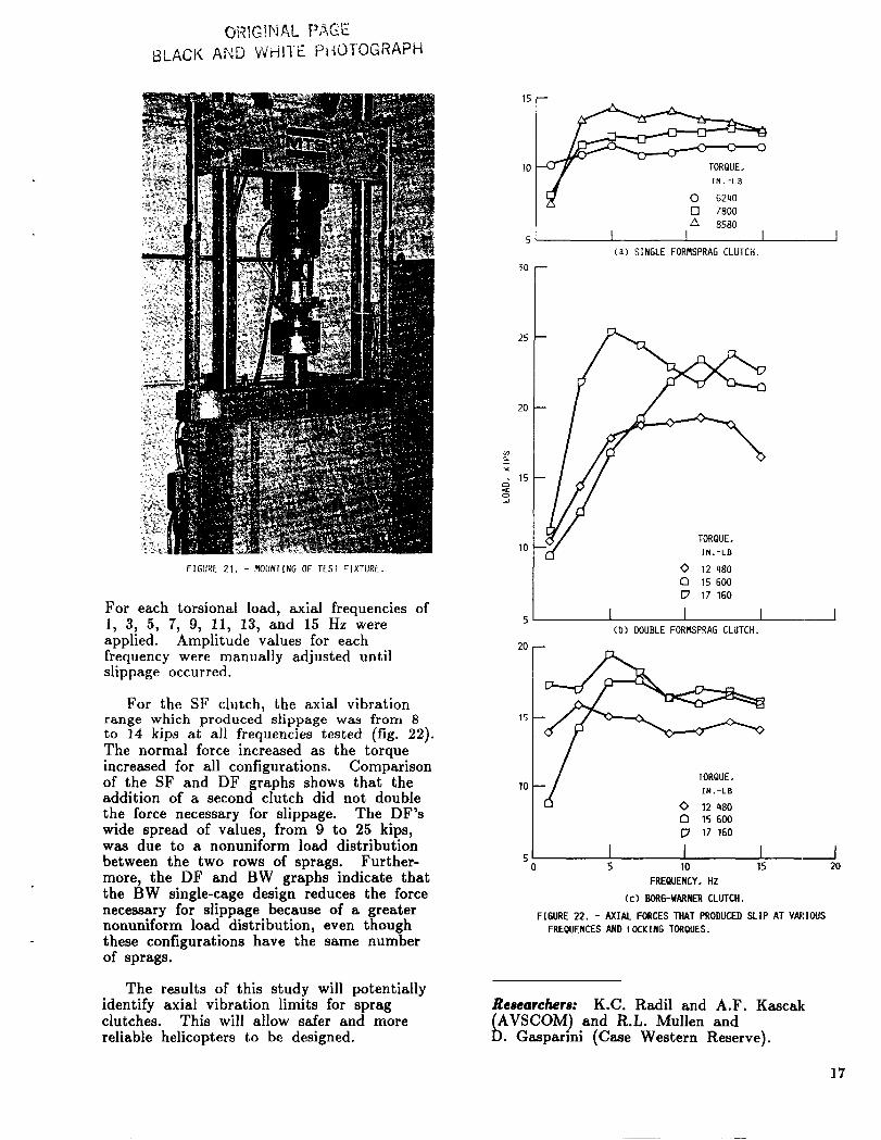
FIGURE 21. - MOUNTINGOF TEST FIXTURE.
For each torsional load, axial frequencies of1, 3, 5, 7, 9, 11, 13, and 15 Hz wereapplied. Amplitude values for eachfrequency were manually adjusted untilslippage occurred.
For the SF clutch, the axial vibrationrange which produced slippage was from 8to 14 kips at all frequencies tested (fig. 22).The normal force increased as the torqueincreased for all configurations. Comparisonof the SF and DF graphs shows that theaddition of a second clutch did not double
the force necessary for slippage• The DF'swide spread of values, from 9 to 25 kips,was due to a nonuniform load distribution
between the two rows of sprags. Further-more, the DF and BW graphs indicate thatthe BW single-cage design reduces the forcenecessary for slippage because of a greaternonuniform load distribution, even thoughthese configurations have the same numberof sprags.
The results of this study will potentiallyidentify axial vibration limits for spragclutches• This will allow safer and morereliable helicopters to be designed.
15
]0
5
3O
25
20
.T.,
10
5
20
15
10
50
[] 7800
/% 8580
I I I(a) SINGLE FORMSPRAG CLUTCH.
F
IN. -LB
0 12 480
C3 15 60O
17 160
I I I(b) DOUBLE FORMSPRAG CLUTCH.
O 15 6O0
[_ 17 160
I I I5 10 15
FREQUENCY. Hz
(c) BORG-WARNER CLUTCH.
FIGURE 22. - AXIAL FORCES THAT PRODUCED SLIP AT VARIOUS
FREQUENCES AND LOCKING TORQUES.
Re,archers: K•C. Radil and A.F. Kascak
AVSCOM) and R.L• Mullen and• Gasparini (Case Western Reserve).
I20
17
Survey of Requirements forMicrogravity-Experiment Mechanisms
The development of automated techniquesfor moving sensitive specimens withoutexceeding certain acceleration thresholds is
critical to successful microgravity experi-mentation on Space Station Freedom andother future free-flying platforms. To betterdefine these critical acceleration levels and
uncover specific requirements for micro-
gravity experiment mechanisms, a surveyquestionnaire was sent out to over 30 prin-cipal investigators working in this field.Responses came from researchers with
planned microgravity experiments in theareas of protein crystal growth, solutioncrystal growth, and directional solidification
of alloys, as well as others. Many of theresponses indicated the need for advanced
mechanism concepts and improved designmethodology. There are at least twoimportant reasons for developing advancedmicrogravity-laboratory mechanisms androbotics. First, automation will ease thedemands on the crew's time, which isalready limited by the many other tasksthey must perform. And second, the crew'sinteraction with experiments could actuallyadversely affect the results of some studiesby upsetting the microgravity levels.
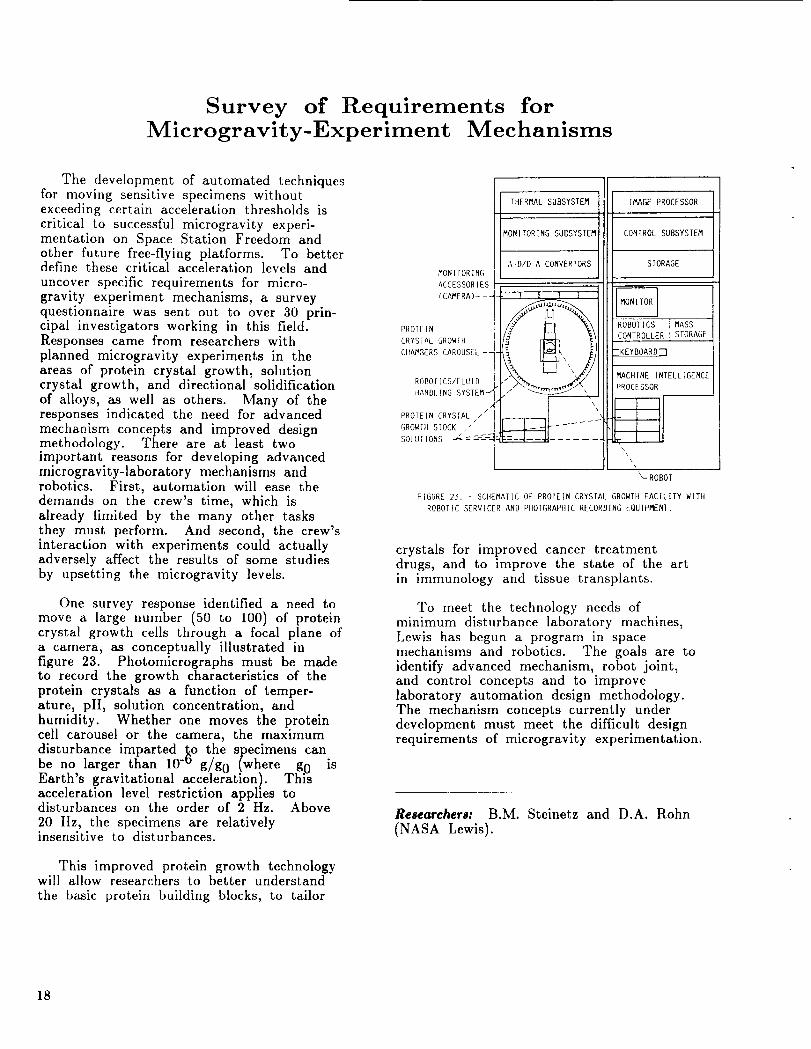
One survey response identified a need to
move a large number (50 to 100) of proteincrystal growth cells through a focal plane ofa camera, as conceptually illustrated infigure 23. Photomicrographs must be madeto record the growth characteristics of theprotein crystals as a function of temper-ature, pH, solution concentration, andhumidity. Whether one moves the proteincell carousel or the camera, the maximum
disturbance imparted _o the specimens canbe no larger than 10- g/g0 (where gf/ isEarth's gravitational acceleration). Thl'_acceleration level restriction applies todisturbances on the order of 2 Hz. Above
20 Hz, the specimens are relativelyinsensitive to disturbances.
This improved protein growth technologywill allow researchers to better understand
the basic protein building blocks, to tailor
MONITORING
ACCESSORIES
(CAMERA)---
PROIEIN
CRYSTAL GROWIII
CIIAMRERS CAROUSEL --
ROBOTICS/FLUID
HANDI_ING SYSTEM J
/
PROTEIN CRYSTAL //
GROWTII STOCK _"SOLUTIONS -_C= :---_-_
THERMAL SUBSYSTEM
MONITORING SUBSYSTEM
A-D/D-A CONVERTORS
I I I I\
IMAGE PROCESSOR
CONTROL SUBSYSTEM
STORAGE
ROBOTICS I MASS
CONTROLLER ]STORAGE
ZKEYBOARD]
MACHINE INTELL[GENCE
PROCESSOR
_-ROBOT
FIGURE 23. - SCIIEMAIIC OF PROTEIN CRYSrAL GROWTH FACILITY WITH
ROBOTIC SERVICER AND PHOTGRAPHIC RECORDING EQUIPMENT.
crystals for improved cancer treatmentdrugs, and to improve the state of the artin immunology and tissue transplants.
To meet the technology needs ofminimum disturbance laboratory machines,Lewis has begun a program in spacemechanisms and robotics. The goals are toidentify advanced mechanism, robot joint,and control concepts and to improvelaboratory automation design methodology.The mechanism concepts currently underdevelopment must meet the difficult designrequirements of microgravity experimentation.
Researchers: B.M. Steinetz and D.A. Rohn
(NASA Lewis).
18
One-Degree-of-Freedom Reactionless Mechanism
Space Station Freedom and future spaceplatforms will provide the scientificcommunity with expanded microgravitylaboratory facilities. Using and maintainingthe microgravity environment will requirecareful attention to the design and develop-ment of apparatus for conducting experi-ments. Since experiments that requiremicrogravity often require physical motion,techniques are required to keep thesemotions and motion-producing forces fromdisturbing the experiment or its sur-roundings. The Reactionless MicrogravityMechanisms and Robotics project isdeveloping precise, smooth, mechanicalmotion control technology for future spacelaboratory use.
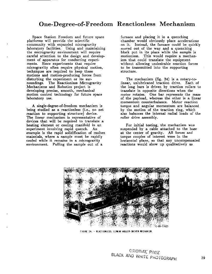
A single-degree-of-freedom mechanism isbeing studied as a reactionless (i.e., no netreaction to supporting structure) device.The linear mechanism is representative ofdevices that will be required to translate aheating element or cooling manifold in anexperiment involving rapid quench. Anexample is the rapid solidification of moltenmaterials, where a sample must be rapidlycooled while it remains in a microgravityenvironment. Pulling the sample out of a
furnace and placing it in a quenchingchamber would obviously place accelerationson it. Instead, the furnace could be quicklymoved out of the way and a quenchingblock put in its place while the sample ismotionless. This would require a mechan-ism that could translate the equipmentwithout allowing undesirable reaction forcesto be transmitted into the supportingstructure.
The mechanism (fig. 24) is a rotary-to-linear, unlubricated traction drive. Each ofthe long bars is driven by traction rollers totranslate in opposite directions when themotor rotates. One bar represents the :massof the payload, whereas the other is a linearmomentum counterbalance. Motor reaction
torque and angular momentum are balancedby the motion of the traction ring, whichalso balances the internal radial loads ot" the
roller drive assembly.
For initial testing, the mechanism wa_suspended by a cable attached to the b_iseat the center of gravity. All forces andtorque couples of interest were in thehorizontal plane, so that any uncompensatedreactions would show up qualitatively as
FIGURE 24. - REACTIONLESS. LINEAR ROLLER-DRIVEN I'IECHANISM.
BLACK AND WHITE PHOI+OGRAPH 19
swinging or swaying motions of the base.Operation showed that the net reactionforces and torques exerted on the base werenearly zero. Deliberate mismatch of bar orring mass produced visible base motion fromthe uncompensated reactions.
Plans for further experimentation involvedetailed load cell measurements of the
effects of mass and momentum imbalance,support bearing friction, traction forces,roller materials, and drive motor character-
istics. Numerical analysis is also underwayto model these effects. Technologydeveloped in this proof-of-concept mechanismwill be available for designers to incorporateinto future prototypes for specific spaceexperiment applications.
Researchers: D.A. Rohn (NASA Lewis) andJ.H. Miller (Sverdrup).
2O
New Results Concerning the Use of KinematicallyRedundant Manipulators inMicrogravity Environments
Experimentation and manufacturing inthe microgravity environment of SpaceStation Freedom must be conducted and
operated without contaminating the environ-ment with vibrations that disturb the
ongoing processes. Robots can be ideal forthis work because they are capable ofprecisely controlled motion. There are twoproblems associated with material handlingm a microgravity environment. The first istransporting specimens without exceedingmicrogravity accelerations on them. Thesecond is operating the handler withoutdisturbing the microgravity environment withthe base reactions or motions of thehandler.
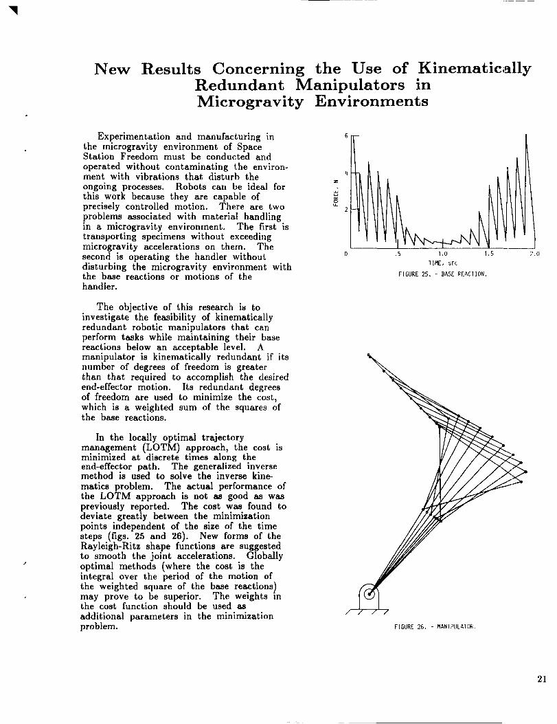
The objective of this research is toinvestigate the feasibility of kinematicallyredundant robotic manipulators that canperform tasks while maintaining their basereactions below an acceptable level. Amanipulator is kinematically redundant if itsnumber of degrees of freedom is greaterthan that required to accomplish the desiredend-effector motion. Its redundant degreesof freedom are used to minimize the cost,which is a weighted sum of the squares ofthe base reactions.
In the locally optimal trajectorymanagement (LOTM) approach, the cost isminimized at discrete times along theend-effector path. The generalized inversemethod is used to solve the inverse kine-
matics problem. The actual performance ofthe LOTM approach is not as good as waspreviously reported. The cost was found todeviate greatly between the minimizationpoints independent of the size of the timesteps (figs. 25 and 26). New forms of theRayleigh-Ritz shape functions are suggestedto smooth the joint accelerations. Globally
optimal methods (where the cost is theintegral over the period of the motion ofthe weighted square of the base reactions)may prove to be superior. The weights inthe cost function should be used as
additional parameters in the minimizationproblem.
6
.5 1.0 1 .S
1 IME, SFC
2.0
FIGURE 25. - BASE REACIION.
/
21
DESIRED
END-EFFECTOR
PAIH _
__ IRAJECIORY
PLANNING
ACIUAL
JOINT JOINT
IRAJEC- IOTAL TRAJEC-
TORIES'7 _-JOINI JOINT IORIES_; /
I , _ _,TORQUES-- TORQUESTF--"----"I / I
I TORQUE I ACIUAL
BASE _' CORRECIION JOINT _, BASE
REACTI ONS CORRECTION 7 REACT IONS
ROBOT I
KINE_9%IICS I
/
_]NVERSE I-
oC-I IK,NE ,,CsIPA'"ERROR
END EFFECIOR
PADt
FIGURE 27, - CONIROI SIRAIEGY.
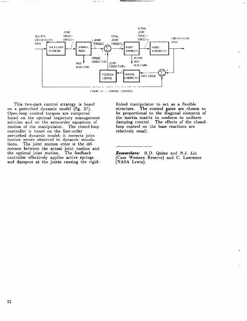
This two-part control strategy is based
on a perturbed dynamic model (fig. 27).Open-loop control torques are computedbased on the optimal trajectory managementsolution and on the zero-order equations of
motion of the manipulator. The closed-loopcontroller is based on the first-order
perturbed dynamic model; it corrects jointmotion errors observed in dynamic simula-tions. The joint motion error is the dif-cerence between the actual joint motion andthe optimal joint motion. The feedbackcontroller effectively applies active springsand dampers at the joints causing the rigid-
linked manipulator to act as a flexiblestructure. The control gains are chosen tobe proportional to the diagonal elements ofthe inertia matrix to conform to uniform
damping control. The effects of the closed-loop control on the base reactions are
relatively small.
Reaearehers: R.D. Quinn and N.J. LinCase Western Reserve) and C. LawrenceNASA Lewis).
22
A Global Approach for Using Kinematic Redundancyto Minimize Base Reactions of Manipulators Used
in Microgravity Environments
In the near future, autonomous roboticmanipulators will be used on space stationsto perform exhaustive tasks such as repair-ing the station's exterior and performingdelicate experiments under microgravityconditions. Such manipulators will, ingeneral, have redundant degrees of freedom
in order to perform tasks. (It is wellknown that redundant manipulators can beused to avoid obstacles and singularconfigurations.)
An issue of considerable importance formanipulators used in microgravity environ-ments is the minimization of the magnitudesof the dynamic reaction forces and momentsexerted by the manipulator on its base as itperforms its task. Furthermore, the basereactions of these manipulators should beminimized or eliminated so that their baseforces and moments do not disturb other
tasks or experiments in the vicinity.
A local approach to this problem was
previously described and implemented.However, the local approach led to undesir-able peaks in the base reactions at certaininstants of time. To smooth out these
undesirable peaks, a global approach thatuses an integral performance index over theentire end-effector trajectory was imple-mented and a performance index, or costfunction, was minimized at each point ofthe end-effector trajectory in order todetermine the joint-space trajectories.
The basic rationale which underlies the
global approach is as follows. Planning atrajectory for a manipulator reduces to theproblem of solving the inverse-kinematicproblem for the joint-variables, or joint-space, trajectory given the specified trajec-tory in the task space. In the case of a
(kinematically) redundant manipulator, theinverse-kinematic problem has an infinitenumber of solutions. An optimizationproblem of minimizing the base reactionswas posed to obtain a unique solution tothe inverse-kinematic problem: in this waythe redundant degrees of freedom were usedto obtain joint-space trajectories that
minimize base reactions. In the presentresearch, an integral performance index
(which is a function of the reaction forcesand moments exerted on the base) isminimized.
To minimize the base reactions, the jointtrajectories must be smooth. In addition,the angular velocity and acceleration at boththe initial and end points of the jointtrajectory should be zero. High-orderpolynomials (or splines) can represent thisfamily of curves by satisfying the velocityand acceleration boundary conditions. Sincevery high order polynomials behave unpre-dictably, the joint trajectory is often brokeninto a number of segments which can berepresented by lower-order polynomials, suchas third and fourth order. These segmentssatisfy the boundary conditions and arecontinuous from one segment to another. Inthis research, a three-segment method wasconsidered. It consists of initial, transi-tional, and final segments. Two fourth-order polynomials are used for the initialand final segments, and a third-order
polynomial is used for the transitionalsegment. This method is also known as the4-3-4 joint trajectory representation. Thecurves described by this method are fun,=-
tions of the initial and final joint positions,the time period of the transitional segment,and the distance traversed during the transi-tional period.
For a redundant manipulator with (m-n)degrees of redundancy, applying the three
parameters scheme to the redundant jointvariables, there are 3(m-n) independentvariables. To determine the optimal values
for vectors a, B, and Of, a performanceindex or cost function Is used as a criterion.
The present approach solves the joint w_ri-ables by posing the minimization of thebase reactions problem as an optimizationproblem.
Researchers: C.L. Chung and S. Desa
(Carnegie-Mellon University) andC. Lawrence (NASA Lewis).
23
Characterization of Structural Connections byUsing Free and Forced Response Test Data
The need for parameter identificationmethods to improve structural dynamicmodels has been increasing. The ability ofengineers to construct complex analyticalmodels has increased; however, they are stillunable to adequately simulate observedresponse with those models. Although great
strides in computer technology and analyti-cal methods have enabled engineers to solvevery large and complex structural problemstheoretically, the results often do notcompare well with test data because of
inaccuracies in the parameters of themathematical model.
Parameter identification methods may beused to determine structural connection
properties. Since connections usuallycontribute significantly to the overall systemstiffness, damping, and in many casesnonlinearity, it is critical that reliableconnection models be made available. For
many structural systems, the constituent
components often can be modeled accurately:the connections contain most of the
modeling uncertainty. Therefore_ accuratesystem response predictions often are highlydependent on valid connection models.
In the present research, parameteridentification methods are extended so that
they can be used for the identification oflinear as well as nonlinear connection
parameters. The present procedure issuitable for processing test data that havebeen measured at arbitrary stations on thestructural system. The data need not bemeasured directly at the connectionboundaries. This flexibility is highlydesirable because in most practical situationsit is impossible to obtain test data at theconnection boundaries, and other identifi-cation methods are ineffective.
The procedure requires verified analyticalmodels of the individual components,although the connection parameters to beidentified may be nonlinear, and velocity ordisplacement dependent. Adequate, transienttime-domain response data are required forthe assembled structural system; the locationof data measurement stations is, however,
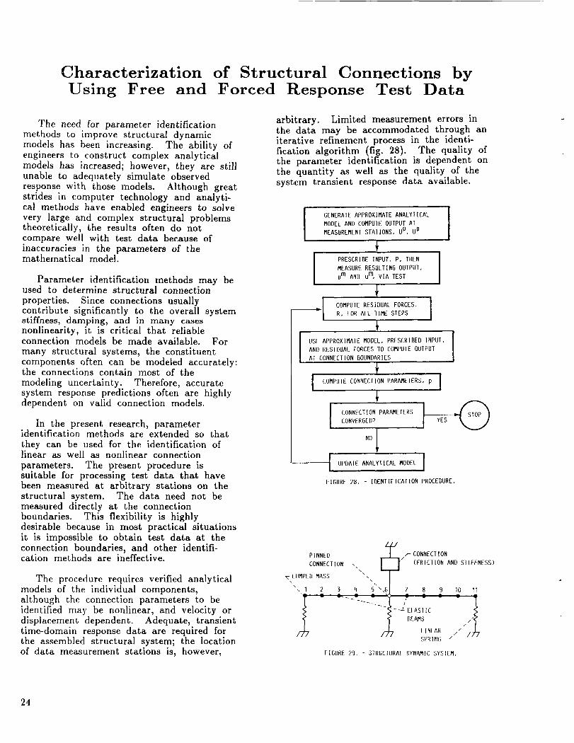
arbitrary. Limited measurement errors inthe data may be accommodated through aniterative refinement process in the identi-fication algorithm (fig. 28). The quality ofthe parameter identification is dependent onthe quantity as well as the quality of thesystem transient response data available.
GENERAIE APPROXIMATE ANALYHEAL
MODEL AND COMPUTE OUIPUT AT
MEASUREMENT STATIONS, U p, U p
!MEASURE RESULTING OUTPUT,
um AND u m VIA TEST
1COMPUTE RESIDUAL FORCES,
R, FOR ALL TIME STEPS
USE APPROXIMAIE MODEL, PRESCRIBED INPUT, ]AND RESIDUAL FORCES EO COMPUTE OUTP
AT ONNECTION BOUNDARIES
!COMPUIE CONNECTION PARAMEIERS, ]
CONNECTION PARAMETERS
CONVERG[I)9
NO
-- UPDAIE ANALYTICAL MODEL
FIGURE 28. - IDENIIFICATION PROCEDURE.
PINNED
CONNECTION
"T LUMPED MASS
,, I 2
\i_/'-CONNECTION
(FRICTION AND SIIFENESS)
\\
3 4 S 7 8 9
- --LEt AS] IC
BEAMS
/_, L INI ARSPRIt!§
I0 11
///
FIGURE 29. - 51RUCIURAL I)YNAMIC 5YSIEM.
24
lOxlO 3
F _ _ COEFFICIENT
/ I _ OF varIatIon 3ox_8 F I | _ ACTUAL
U ...
'1 I I I I I I0 5 10 15 20 0 5 10
I IERAT ] ON I TERAI I ON
(a) FRICTION. (b) LINEAR SPRING.
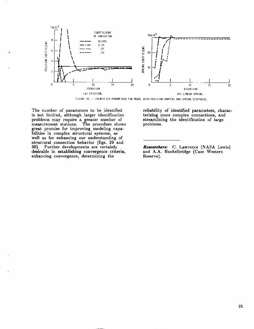
FIGURE 30. - Ir)ENTIFI[D PARAMETERSFOR MODELWITII FRICTION DAMPINGAND SPRING STIFFNESS.
I I15 20
The number of parameters to be identifiedis not limited, although larger identificationproblems may require a greater number ofmeasurement stations. The procedure showsgreat promise for improving modeling capa-bilities in complex structural systems, aswell as for enhancing our understanding ofstructural connection behavior (figs. 29 and30). Further developments are certainlydesirable in establishing convergence criteria,enhancing convergence, determining the
reliability of identified parameters, charac-terizing more complex connections, andstreamlining the identification of largeproblems.
Researchers: C. Lawrence (NASA Lewis)and A.A. Huckelbridge (Case WesternReserve).
25
Distributed
Using a
Finite element analysis is used extensivelyin evaluating the load and life capabilitiesof structures from small to large and simpleto complex. Complex structures with thou-sands of independent degrees of freedom,typically, are analyzed by using expensivesupercomputers for reasonable computationtimes. However, the performance of super-computers can be approached and evenexceeded with parallel processing networksthat use low-cost processors.
Under a Small Business InnovationResearch contract to the NASA Lewis
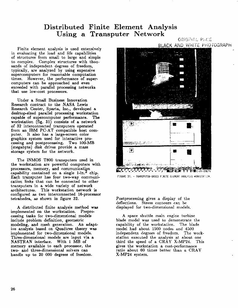
Research Center, Sparta, Inc., developed adesktop-sized parallel processing workstationcapable of supercomputer performance. Theworkstation (fig. 31) consists of a networkof 32 interconnected transputers operatedfrom an IBM PC-AT compatible host com-puter. It also has a large-screen color
grap.hics system used for interactive pro-cessmg and postprocessing. Two 100-MB(megabyte) disk drives provide a massstorage system for the network.
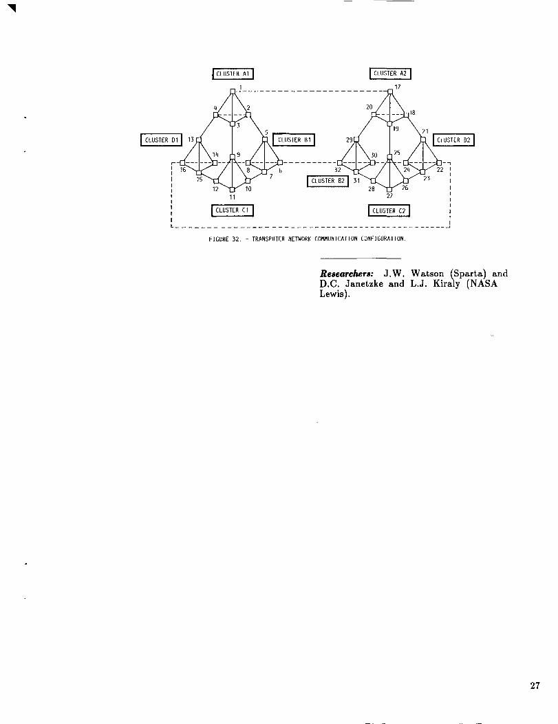
The INMOS T800 transputers used inthe workstation are powerful computers withprocessors, memory, and communicatigncapability contained on a single 1-in. _ chip.Each transputer has four two-way communi-cation links that can be connected to othertransputers in a wide variety of networkarchitectures. This workstation network is
configured as two interconnected 16-processortetrahedra, as shown in figure 32.
A distributed finite analysis method wasimplemented on the workstation. Prepro-cessing tasks for two-dimensional modelsinclude problem definition, geometricmodeling, and mesh generation. An adapt-ive analysis based on Quadtree theory wasimplemented for two-dimensional models.Three-dimensional models are input via aNASTRAN interface. With 1 MB ofmemory available to each processor, thetwo- and three-dimensional solvers canhandle up to 20 000 degrees of freedom.
Finite Element AnalysisTransputer Network
BLACK AND WHITE FHOTOGRAPH
FIGURE 31. - TRANSPUTER-BASED FINITE ELEMENT ANALYSIS WORKSTAIION.
Postprocessing gives a display of thedeflections. Stress contours can be
displayed for two-dimensional models.
A space shuttle main engine turbineblade model was used to demonstrate the
capability of the workstation. The blademodel had about 1500 nodes and 4500independent degrees of freedom. The work-station executed the analysis at about onethird the speed of a CRA¥ X-MP24. Thisgives the workstation a cost-performanceratio about 60 times better than a CRAYX-MP24 system.
26
I CLUSTER AI J I CLUSIER A2 I
I 17
/ I \s / I'" \21 ,-
..........7
11 27
I_'U_R_ I I_o_,_R_ I
FIGURE 32. - TRANSPUTER NETWORK COMMUNICATION CONFIGURATION.
Researchers: J.W. Watson (Sparta) andD.C. Janetzke and L.J. Kiraly (NASALewis).
27
Shape and Topology Optimization by theHomogenization Method
A major difficulty in optimizing theshape of linearly elastic structures is causedby large domain changes during the optimiz-ation process which require the domain tobe rediscretized for the finite element stress
analysis. Furthermore, changes of topology,such as the introduction of weight-savingholes in the structure, are virtually impos-
sible with existing optimization approaches,unless they are done manually. A newmethod is under development to overcomethe limitations of traditional shape optimiza-tion. Optimization and discretization are
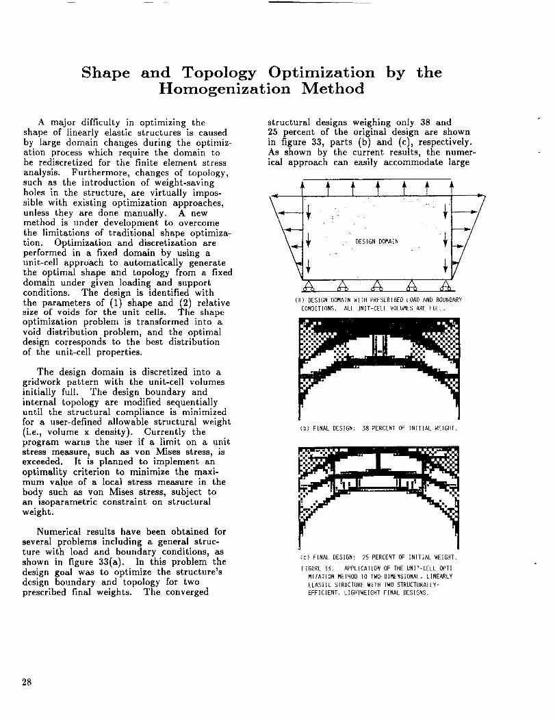
performed in a fixed domain by using aunit-cell approach to automatically generatethe optimal shape and topology from a fixeddomain under given loading and supportconditions. The design is identified withthe parameters of (1) shape and (2)relativesize of voids for the unit cells. The shapeoptimization problem is transformed into avoid distribution problem, and the optimaldesign corresponds to the best distributionof the unit-cell properties.
The design domain is discretized into agridwork pattern with the unit-cell volumesinitially full. The design boundary andinternal topology are modified sequentiallyuntil the structural compliance is minimizedfor a user-defined allowable structural weight
(i.e., volume x density). Currently theprogram warns the user if a limit on a unitstress measure, such as von Mises stress, isexceeded. It is planned to implement an
optimality criterion to minimize the maxi-mum value of a local stress measure in the
body such as yon Mises stress, subject toan isoparametric constraint on structuralweight.
Numerical results have been obtained for
several problems including a general struc-ture with load and boundary conditions, as
shown in figure 33(a). In this problem thedesign goal was to optimize the structure'sdesign boundary and topology for twoprescribed final weights. The converged
structural designs weighing only 38 and25 percent of the original design are shownin figure 33, parts (b) and (c), respectively.As shown by the current results, the numer-ical approach can easily accommodate large
(a) DESIGN DOMAIN WITH PRESCRIBED LOAD AND BOUNDARY
CONDITIONS. ALL UNIT-CELL VOLUMES ARE FULL.
(b) FINAL DESIGN: 38 PERCENT OF INITIAL WEIGHT.
(c) FINAL DESIGN: 25 PERCENT OF INITIAL WEIGHT.
FIGURE 33. - APPLICATION OF THE UNIT-CELL OPTI-
MIZATION METHOD TO TWO-DIMENSIONAL, LINEARLY
ELASTIC STRUCTURE WITH TWO STRUCTURALLY-
EFFICIENT, LIGHTWEIGHT FINAL DESIGNS.
28

movements of the design boundary andautomatically introduce weight-saving cutouts
in lightly loaded areas.
The numerical approach can also be usedto analyze composite material structures.
Modeling the matrix and fibers with unit-cells having appropriate stiffness properties,
the macroscale elastic constants are deter-
mined by using the homogenization method.
Researchers: N. Kikuchi and J. Taylor
University of Michigan) and B.M. SteinetzNASA Lewis).
29
Parallel Time Integration of Finite Element Problems
In this study, a system of transputercomputers was used to solve structuraldynamics problems. A transputer is a chip-level computer with local memory and fourasynchronous communication channels thatcan be linked to other transputers. Thetransputers can be arranged in a variety ofconfigurations; however, each transputer canhave at most four neighbors. In this studya pipeline configuration was used. Thetransputers were programmed using theOCCAM language, which simplifies the
programming of parallel algorithms.
The central difference rule (a direct timeintegration method) was used to solve thegoverning structural dynamics equations.With direct integration methods the timeperiod of interest is divided into intervals orsteps, and the solution is progressivelycomputed at each of these time steps. Thecentral difference method is said to be an
explicit method since it does not require thesolution of algebraic equations. Therefore,the displacement at a node can be computedindependently of the other nodes. Forparallel processing, the nodes of the meshare partitioned into groups. These groupsare assigned to different processors for
updating, and information is exchangedbetween processors after each update. Inthis study, only nearest-neighbor communi-cation was necessary.
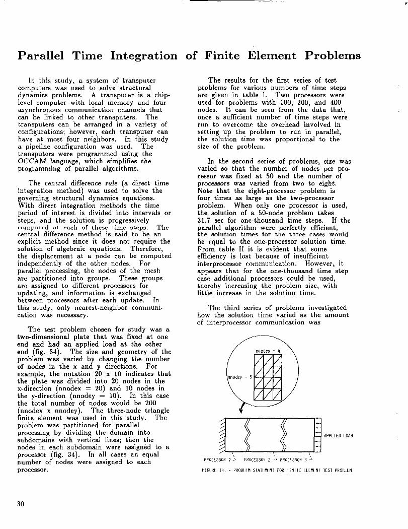
The test problem chosen for study was atwo-dimensional plate that was fixed at oneend and had an applied load at the otherend (fig. 34). The size and geometry of theproblem was varied by changing the numberof nodes in the x and y directions. Forexample, the notation 20 x 10 indicates thatthe plate was divided into 20 nodes in thex-direction (nnodex = 20) and 10 nodes inthe y-direction (nnodey = 10). In this casethe total number of nodes would be 200
nnodex x nnodey). The three-node trianglenite element was used in this study. The
problem was partitioned for parallelprocessing by dividing the domain intosubdomains with vertical lines; then thenodes in each subdomain were assigned to a
processor (fig. 34). In all cases an equalnumber of nodes were assigned to each
processor.
The results for the first series of test
problems for various numbers of time stepsare given in table I. Two processors wereused for problems with 100, 200, and 400nodes. It can be seen from the data that,
once a sufficient number of time steps wererun to overcome the overhead involved in
setting up the problem to run in parallel,the solution time was proportional to thesize of the problem.
In the second series of problems, size wasvaried so that the number of nodes per pro-cessor was fixed at 50 and the number of
processors was varied from two to eight.Note that the eight-processor problem isfour times as large as the two-processorproblem. When only one processor is used,
the solution of a 50-node problem takes31.7 sec for one-thousand time steps. If theparallel algorithm were perfectly efficient,the solution times for the three cases would
be equal to the one-processor solution time.From table II it is evident that some
efficiency is lost because of insufficientinterprocessor communication. However, itappears that for the one-thousand time stepcase additional processors could be used,thereby increasing the problem size, withlittle increase in the solution time.
The third series of problems investigatedhow the solution time varied as the amount
of interprocessor communication was
PROEESSOR _ _ PROEESSOR 2 -_ PROEESSOR 5 _
FIGURE 34. - PROBLEM SiAIEMENT FOR FINIIE I:_LLMLN] lEST PROI3LLM.
3O
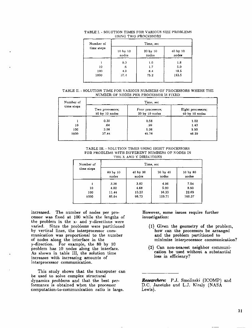
TABLE I. - SOLUTION TIMES FOR VARIOUS SIZE PROBLEMS
USING TWO PROCESSORS
Number of
time steps
1
10
100
1000
lO by 10
nodes
0,3
.6
4,0
37.4
Time, sec
20 by 10
nodes
1.0
1.7
8.4
75.2
40 by 10
nodes
1.8
5.0
18.5
153.5
TABLE II, - SOLUTION TIME FOR VARIOUS NUMBERS OF PROCESSORS WHERE THE
NUMBER OF NODES PER PROCESSOR IS FIXED
Number of
time steps
1
10
100
1000
Two processors;
10 by 10 nodes
0.30
.64
3.98
37.44
Time, sec
Four processors; Eight processors;
20 by 10 nodes 40 by 10 nodes
0,58
.99
5.06
45.78
1.02
1.43
5.50
46.29
TABLE III. - SOLUTION TIMES USING EIGHT PROCESSORS
FOR PROBLEMS WITH DIFFERENT NUMBERS OF NODES IN
THE X AND Y DIRECTIONS
Number of Time, sec
time steps
80 by 10 40 by 20 20 by 40 10 by 80
nodes nodes nodes nodes
1
10
100
1000
3.28
4.02
11.44
85.64
3.83
4.68
13.23
98.73
4.96
5.99
16,33
119.71
7.54
8.92
22.69
160.37
increased. The number of nodes per pro-cessor was fixed at 100 while the lengths ofthe problem in the x- and y-directions werevaried. Since the problems were partitionedby vertical lines, the interprocessor com-munication was proportional to the numberof nodes along the interface in they-direction. For example, the 80 by 10problem has 10 nodes along the interface.As shown in table III, the solution timeincreases with increasing amounts ofinterprocessor communication.
This study shows that the transputer canbe used to solve complex structuraldynamics problems and that the best per-formance is obtained when the processorcomputation-to-communication ratio is large.
However, some issues require furtherinvestigation:
(1) Given the geometry of the problem,how can the processors be arrangedand the problem partitioned tominimize interprocessor communication?
(2) Can non-nearest neighbor communi-cation be used without a substantial
loss in efficiency?
Researchers: P.J. Smolinski (ICOMP) andD.C. Janetzke and L.J. Kiraly (NASALewis).
31
Structural Design of a 6-MW Solar Electric
Propulsion (SEP) Spacecraft forMission to Mars
A preliminary estimate of the structuralconfiguration and mass for the proposedSolar Electric Propulsion (SEP) MarsSpacecraft recently was completed. Thedesign is based on a 6.32-MW initialpower spe_qification and an array area of38 028 m _. The payload and thrustermasses were specified as 400 000 and115 000 kg, respectively.
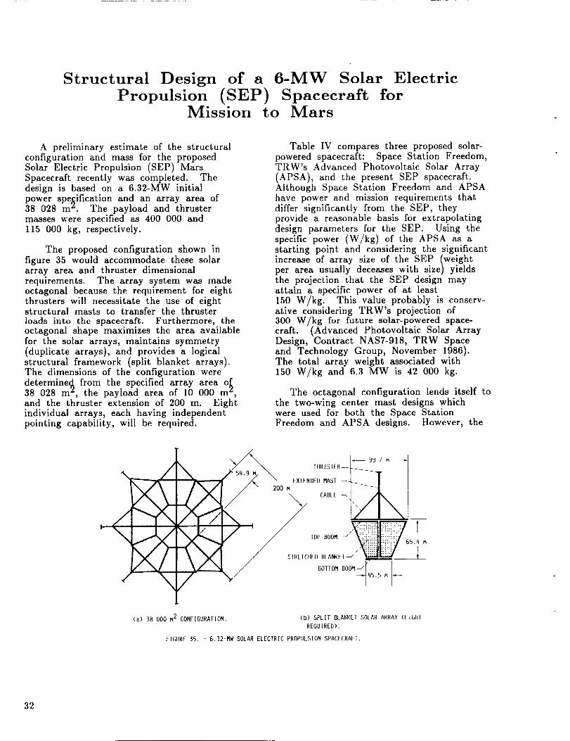
The proposed configuration shown in
figure 35 would accommodate these solararray area and thruster dimensionalrequirements. The array system was madeoctagonal because the requirement for eightthrusters will necessitate the use of eightstructural masts to transfer the thrusterloads into the spacecraft. Furthermore, theoctagonal shape maximizes the area availablefor the solar arrays, maintains symmetry(duplicate arrays), and provides a logicalstructural framework (split blanket arrays).The dimensions of the configuration were
determine_ from the specified array area o438 028 m _, the payload area of 10 000 m _,and the thruster extension of 200 m. Eightindividual arrays, each having independentpointing capability, will be required.
Table IV compares three proposed solar-powered spacecraft: Space Station Freedom,TRW's Advanced Photovoltaic Solar Array
(APSA), and the present SEP spacecraft.Although Space Station Freedom and APSAhave power and mission requirements thatdiffer significantly from the SEP, theyprovide a reasonable basis for extrapolatingdesign parameters for the SEP. Using thespecific power (W/kg) of the APSA as astarting point and considering the significantincrease of array size of the SEP (weightper area usually deceases with size) yieldsthe projection that the SEP design mayattain a specific power of at least150 W/kg. This value probably is conserv-ative considering TRW's projection of300 W/kg for future solar-powered space-craft. (Advanced Photovoltaic Solar ArrayDesign, Contract NAS7-918, TRW Spaceand Technology Group, November 1986).
The total array weight associated with150 W/kg and 6.3 MW is 42 000 kg.
The octagonal configuration lends itself to
the two-wing center mast designs whichwere used for both the Space StationFreedom and APSA designs. However, the
I _.//_ I--- _<Ji . ..Ilk 2" \ IiirUglER--L_ [
I/_, \! I _/ \ CA.,__t /q',, I
x t(..j..::Z_
v_ / .otto. _oo_-,[ I
Ca) 38 000 M2 CONFIGURATION. (b) SPLIt BI.ANK[1 SOLAR ARRAY ([IGtll
REQU IREI)),
FIGURE 35. - G,32-MW SOLAR ELECTRIC PROPULSION SPACECRAFT.
32
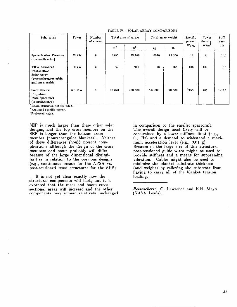
TABLE IV. - SOLAR ARRAY COMPARISONS
Solar array
Space Station Freedom
(low-earth orbit)
TRW Advanced
Photovoitalc
Solar Array
(geosynchronous orbit;
gallium arsenide)
Sol_r Electric
Propulsion
Mars Spacecraft
(interplanetary)
Power
75 kW
I0 kW
6.3 MW
Number
of arrays
Total area of arrays
2m ft 2
2400 25 800
85 910
38 028 400 000
Total array weight
kg Ib
6080 13 300
76 168
"42 000 90 000
Specific
power,
W/kg
12
136
b150
Power
density,
W/m 2
31
134
166
Stiff-
heSS,
Hz
0.10
.10
'<.1o
*Boom extension not included.
bAssumed specific power.
eProjected value.
SEP is much larger than these other solardesigns, and the top cross member on theSEP is longer than the bottom crossmember (nonrectangular blankets). Neitherof these differences should present com-plications although the design of the crossmembers and boom probably will differbecause of the large dimensional dissimi-larities in relation to the previous designs(e.g., continuous beams for the APSA vs.post-tensioned truss structures for the SEP).
It is not yet clear exactly how thestructural components will look, but it isexpected that the mast and boom cross-sectional areas will increase and the othercomponents may remain relatively unchanged
in comparison to the smaller spacecraft.The overall design most likely will beconstrained by a lower stiffness limit (e.g.,0.1 Hz) and a demand to withstand a maxi-mum acceleration level (e.g., 0.01 g).Because of the large size of this structure,post-tensioned guide wires might be used toprovide stiffness and a means for suppressingvibration. Cables might also be used tominimize the blanket substrate thickness
(and weight) by relieving the substrate fromhaving to carry all of the blanket tensionloading.
Researchers: C. Lawrence and E.H. Meyn(NASA Lewis).
33
Solution and Sensitivity Analysis of a ComplexTranscendental Eigenproblem With
Pairs of Real Eigenvalues
Dynamic stability analysis of aeroelasticsystems consists of finding the real values ofMach number M and vibration frequencythat satisfy the following equations ofmotion:
[-_2M + K - Cl(M,a)} q = 0
where M, K, and C are the generalizedmass, stiffness, and aerodynamic matrices,respectively. The aerodynamic matrix is atranscendental function of M and _.
These equations can be viewed as defining acomplex transcendental eigenvalue problem of
the form A()'l,)'2)u = 0 with pairs of
real eigenvalues defined by )'1 and )'2and with eigenvectors defined by u.
This eigenvalue problem differs in manyrespects from the conventional linear eigen-
value problem defined by (A - )'I)u = 0and the ),-matrix eigenvalue problem
defined by A(),)u = 0. Whereas thelinear and the )`-matrix eigenproblems
define eigenpairs, the eigenvalue problem weconsider defines eigentriples. Also, it is wellknown that, when multiplicity is properlyaccounted for, the number of eigenpairs ofthe linear eigenvalue problem depends onlyon the order of the matrix and, in the caseof the )`-matrix eigenproblem, on the matrixorder and the highest degree of the poly-nomials in )'. In the case of the
transcendental eigenvalue problem, thenumber of the eigentriples is not known inadvance and could be infinite, finite, ornone. In addition, no orthogonality
relationships or canonical forms are knownto exist for the transcendental eigenvalue
problem with pairs of real eigenvalues.
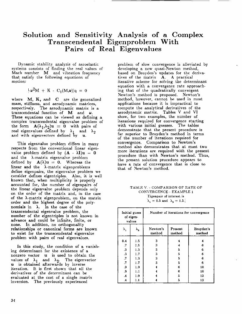
In this study, the condition of a vanish-ing determinant for the existence of anonzero vector u is used to obtain the
values of )'1 and )'2" The eigenvectoru is obtained afterwards by inverseiteration. It is first shown that all thederivatives of the determinant can be
evaluated at the cost of a single matrixinversion. The previously experienced
problem of slow convergence is alleviated bydeveloping a new quasi-Newton method,based on Broyden's updates for the deriva-tives of the matrix A. A practicaliterative scheme for solving the determinantequation with a convergence rate approach-ing that of the quadratically convergentNewton's method is proposed. Newton'smethod, however, cannot be used in mostapplications because it is impractical tocompute the analytical derivatives of theaerodynamic matrix. Tables V and VIshow, for two examples, the number ofiterations required for convergence startingwith various initial guesses. The tablesdemonstrate that the present procedure isfar superior to Broyden's method in termsof the number of iterations required forconvergence. Comparison to Newton'smethod also demonstrates that at most two
more iterations are required with the presentprocedure than with Newton's method. Thus,the present solution procedure appears tohave a rate of convergence that is close tothat of Newton's method.
TABLE V. - COMPARISON OF RATE OFCONVERGENCE- EXAMPLE 1
[Eigenpair of interest is)h = 0.5 and )_ = 1.5.]
Initial guess
of eigen-values
k 1 k2
0.4 1.5.7 1.5.3 1.3.3 1.7.7 1.3.7 1.7.9 1.9.9 I.I
.4 1.9
.4 1.1
Number of iterations for convergence
Newton'smethod
3 43 43 53 5
3 53 54 64 64 54 5
Present Broyden'smethod method
4666
66
I0I01313
34
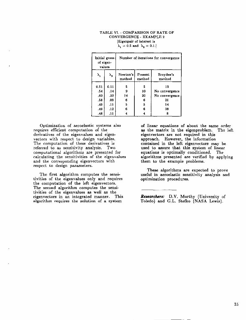
TABLEVI. - COMPARISONOFRATEOFCONVERGENCE- EXAMPLE2
[Eigenpairofinterestis),_= 0.5andX2= 0.1.]
Initialguessofeigen-
values
),1 x2
0.51 0.11.54 .14.60 .20.58 .09.49 .11.49 .12.48 .11
Number of iterations for convergence
Newton's Present Broyden'smethod method method
5 5
9 1014 206 65 5
6 64 4
19
No convergenceNo convergence
2114388
Optimization of aeroelastic systems alsorequires efficient computation of thedcrivatives of the eigenvalues and eigen-
vectors with respect to design variables.The computation of these derivatives is
referred to as sensitivity analysis. Twocomputational algorithms are presented forcalculating the sensitivities of the eigenvaluesand the corresponding eigenvectors withrespect to design parameters.
The first algorithm computes the sensi-tivities of the eigenvalues only and requiresthe computation of the left eigenvectors.The second algorithm computes the sensi-tivities of the eigenvalues as well as theeigenvectors in an integrated manner. Thisalgorithm requires the solution of a system
of linear equations of about the same orderas the matrix in the eigenproblem. The lefteigenvectors are not required in thisapproach. However, the informationcontained in the left eigenvectors may [beused to assure that this system of linearequations is optimally conditioned. Thealgorithms presented are verified by applyingthem to the example problems.
These algorithms are expected to proveuseful in aeroelastic sensitivity analysis andoptimization procedures.
Researchers: D.V. Murthy (University ofToledo) and G.L. Stefko (NASA Lewis).
35
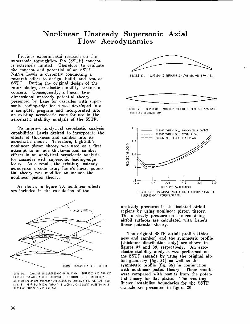
Nonlinear Unsteady Supersonic AxialFlow Aerodynamics
Previous experimental research on thesupersonic throughflow fan (SSTF) conceptis extremely limited. Therefore, to evaluatethe concept and potential of an SSTF,NASA Lewis is currently conducting aresearch effort to design, build, and test anSSTF. During the original design of therotor blades, aeroelastlc stability became aconcern. Consequently, a linear, two-dimensional unsteady potential theorypresented by Lane for cascades with super-sonic leading-edge locus was developed into
a computer program and incorporated intoan existing aeroelastic code for use in theaeroelastic stability analysis of the SSTF.
To improve analytical aeroelastic analysis
capabilities, Lewis desired to incorporate theeffects of thickness and camber into its
aeroelastic model. Therefore, Lighthill'snonlinear piston theory was used as a firstattempt to include thickness and cambereffects in an analytical aeroelastic analysisfor cascades with supersonic leading-edgelocus. As a result, the existing unsteadyaerodynamic code using Lane's linear poten-tial theory was modified to include thenonlinear piston theory.
As shown in figure 36, nonlinear effectsare included in the calculation of the
\
_ ISOLATED AIRFOIL REGION
FIGURf 56. - CASCADE IN SUPERSONIC AXIAL FLOW. SURFACES (1) ANU (2)
EXltlUIF ISOLA[EI) AIRFOIL BEIIAVIOR. LIGHIItlLL'S PISTON TItEORY IS
USEI) I0 CALCIIIATE UNSTEADY PR_-SSURES ON S_IRFACES (1) AND (2), AND
LANE'S LINEAR POIENT]AL "HtEORY IS USE]) IO CALCULAIE UNSIFAI)Y PRLS-
SURFS ON SURFACES (3) AND (q)
FIGURE 37. - SUPERSONIC TIIROUGItFLOW FAN AIRIOI[ PROI-IIL.
FIGURE 38. - SUPERSONIC TIIROUGIIFLOW FAN IIIICKNESS (sYm/'__IRIC
PROFILE) DISTRIBUTION.
1.7|r--- PISION/POTENIIAL, IIIICKNESS + CA/_BER/. PIS ON.OTEN.^ .SY E R,CAL
J . . .
8l I I 1 I I2.0 2.2 2.4 2.6 2.8 3.0
RELAtiVE mACII NUMBER
FIGURE 39. - TORSIONAL mODE FLUTIER BOUNDARY FOR TIIE
SUPERSONIC TIIROUDIIFLOW FAN.
unsteady pressures in the isolated airfoilregions by using nonlinear piston theory.The unsteady pressure on the remainingairfoil surfaces are calculated with Lane's
linear potential theory.
The original SSTF airfoil profile (thick-ness and camber) and the symmetric profile
thickness distribution only) are shown ingures 37 and 38, respectively. An aero-
elastic stability analysis was performed onthe SSTF cascade by using the original air-foil geometry (fig. 37) as well as thesymmetric profile (fig. 39) in conjunctionwith nonlinear piston theory. These resultswere compared with results from the poten-tial theory for flat plates. The resultingflutter instability boundaries for the SSTFcascade are presented in figure 39.
36
The analysis with the symmetric profile(thickness distribution only) decreasedthe stability of the SSTF cascade for2 < M < 2.3 and increased the stability atMach numbers above 2.3 when comparedwith an analysis using linear potentialtheory on flat plates. The inclusion ofthe original airfoil geometry increasedthe predicted stability for Mach numbersslightly above 2 with respect to theanalysis using linear potential theory on
flat plates. The inclusion of camber withthickness (original airfoil geometry) alsoincreased the stability of the SSTF cascadewhen compared with the analysis with thick-hess only (symmetric profile).
Researcher: J.K. Ramsey (NASA Lewis).
37
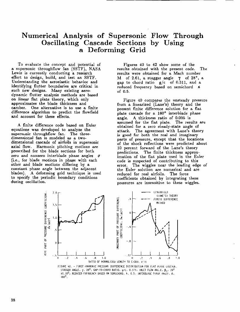
Numerical Analysis of SupersonicOscillating Cascade Sections
a Deforming Grid
Flow Throughby Using
To evaluate the concept and potential of
a supersonic throughflow fan (SSTF), NASALewis is currently conducting a researcheffort to design, build, and test an SSTF.Understanding the aeroelastic behavior andidentifying flutter boundaries are critical insuch new designs. Many existing aero-dynamic flutter analysis methods are basedon linear flat plate theory, which onlyapproximates the blade thickness andcamber. One alternative is to use a finite
difference algorithm to predict the flowfieldand account for these effects.
A finite difference code based on Euler
equations was developed to analyze thesupersonic throughflow fan. The three-dimensional fan is modeled as a two-
dimensional cascade of airfoils in supersonicaxial flow. Harmonic pitching motions areprescribed for the blade sections for both
zero and nonzero interblade phase angles o
(i.e., for blade motions in phase with eachother and blade motions differing by aconstant phase angle between the adjacentblades). A deforming grid technique is usedto specify the periodic boundary conditionsduring oscillation.
Figures 40 to 42 show some of theresults obtained with the present code. Theresults were obtained for a Mach number
M of 2.61, a stagger angle 7 of 28 °, agap to chord ratio g/c of 0.311, and areduced frequency based on semichordof 0.5.
Figure 40 compares the unsteady pressurefrom a linearized (Lane's) theory and thepresent finite difference solution for a flat
plate cascade for a 180 ° interblade phaseangle. A thickness ratio of 0.005 isassumed for the flat plate. The results areobtained for a zero steady-state angle ofattack. The agreement with Lane's theoryis good for both the real and imaginaryparts of pressure, except that the locationsof the shock reflections were predicted about10 percent forward of the Lane's theorypredictions. The finite thickness approx-imation of the flat plate used in the Eulercode is suspected of contributing to thiserror. The wiggles near the leading edge ofthe Euler solution are numerical and arereduced for real airfoils. The force
coefficients obtained by integrating thesepressures are insensitive to these wiggles.
u_ ¢._
2.0
1.5
1.0
0 --
S
5 I I I I I0 .2 .4 .6 .8 1.0
.4
'=if' 0or:
-.4
_ -.8U,
-.12
t.INEARIZLD
(LANE'S) TIIEORY
------ FINI1E DIFFERENCE
_EDJOD
[J S "i
I I 1 I.2 .4 .6 .8
RATIO OF NORMALIZEDLENGTIt TO CItORI), x'/c
FIGURE 40. - FIRST tlARMONICPRESSUREDIFFERENCE DISIRIBUIlON FOR I:IAT PLAIE CASCADE.
STAGGERANGLE, y, 28o; GAP-IO-CHORD RATIO, g/c, 0.311; INLET FLOWANGLE, _7" 28oiO.lO°; REDUCEDFREQUENCYBASED ON SEMICttORD, k, 0.5: INTERBLADEPIIASE ANGLE, O,
1800 .
38
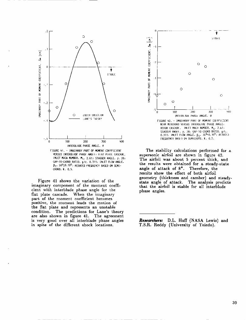
z
:E
.2--
0
0
0
0
C) EULER SOLUTION
LANE'S THEORY
STABLE
0
I I I I-.4
0 100 200 300 400
INTERBLADE PHASE ANGLE, 0
FIGURE 41. - IMAGINARY PART OF i"K]i"_[NTCOEFFICIENT
VERSUS INTERBLADE PHASE ANGLE; FLAT PLATE CASCADE.
INLET MACH NUI'_3ER,MI, 2.61; STAGGER ANGLE, _, 28:GAP-TO-CHORD RATIO, g/c, 0,311; INLET FLOW ANGLE,
_I" 28°-+0'10°:REDUCED FREQUENCY BASED ON SEMI-
CHORD, k, 0.5.
Figure 41 shows the variation of theimaginary component of the moment coeffi-cient with interblade phase angle for thefiat plate cascade. When the imaginarypart of the moment coefficient becomespositive, the moment leads the motion ofthe flat plate and represents an unstablecondition. The predictions for Lane's theoryare also shown in figure 41. The agreementis very good over all interblade phase anglesin spite of the different shock locations.
.-£-.
-3 --
_l I m
-S
SIAIIIL
©©
0
©
©
C j
0©
I l l II00 200 300 (_00
INTERBLADE PHASE ANGLE, 0
FIGURE 42. - Ii'SAGINARYPART OF MOMENT COEFFI,ZIENI
NEAR MIDCIIORDVERSUS INIERBLADE PIIASEANGLE:
ROFOR CASCADE. INLET MACH NUMBER, MI, 2.61:
STAGGER ANGLE, I, 28; GAP-IO-CHORD RATIO, g/c,
0.311_ INLET FLOW ANGLE, _I" sGO_O'lO°; REDUCED
FREQUENCY BASED ON SEMICHORU, k, 0.5.
The stability calculations performed for asupersonic airfoil are shown in figure 42.The airfoil was about 5 percent thick, andthe results were obtained for a steady-stateangle of attack of 8 ° . Therefore, theresults show the effect of both airfoil
geometry (thickness and camber) and s_eady-state angle of attack. The analysis pr,.dictsthat the airfoil is stable for all interbladephase angles.
Researchers: D.L. Huff (NASA Lewis) andT.S.R. Reddy (University of Toledo).
39
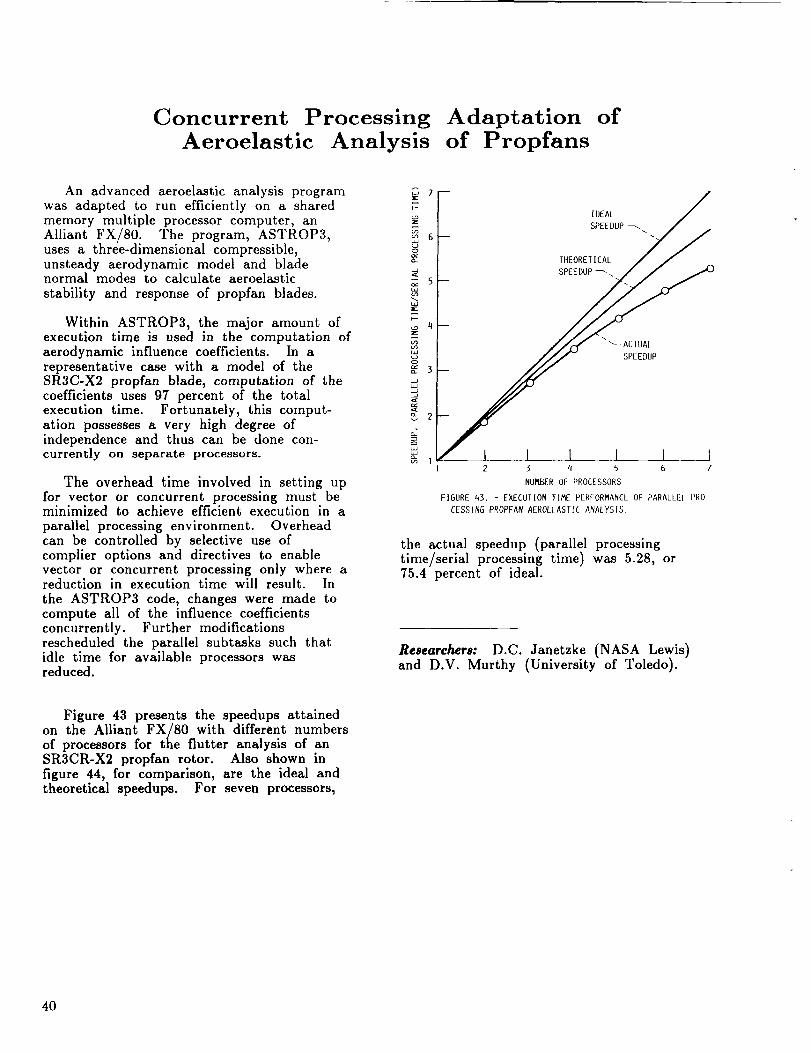
Concurrent Processing Adaptation of
Aeroelastic Analysis of Propfans
An advanced aeroelastic analysis programwas adapted to run efficiently on a sharedmemory multiple processor computer, anAlliant FX/80. The program, ASTROP3,uses a three-dimensional compressible,unsteady aerodynamic model and bladenormal modes to calculate aeroelastic
stability and response of propfan blades.
Within ASTROP3, the major amount ofexecution time is used in the computation ofaerodynamic influence coefficients. In arepresentative case with a model of theSR3C-X2 propfan blade, computation of thecoefficients uses 97 percent of the totalexecution time. Fortunately, this comput-ation possesses a very high degree ofindependence and thus can be done con-currenBly on separate processors.
The overhead time involved in setting upfor vector or concurrent processing must beminimized to achieve efficient execution in a
parallel processing environment. Overheadcan be controlled by selective use ofcompiler options and directives to enablevector or concurrent processing only where areduction in execution time will result. In
the ASTROP3 code, changes were made tocompute all of the influence coefficientsconcurrently. Further modificationsrescheduled the parallel subtasks such thatidle time for available processors wasreduced.
7
_6O
_s
7-
4
_3
_2
[ DEAL /
SPEEDUP _ /
TltEORET 1EAL //
/ I I I I I i_j.sPee,uP
2 ._ q 5 6 7
NUI'_.BER 01: PROCESSORS
FIGURE 43. - EXECUTION liME PERFORMANCE OF PARALLEl PRO
£ESSING PROPFAN AEROt_[ASTIL ANALYSIS.
the actual speedup (parallel processingtime/serial processing time) was 5.28, or75.4 percent of ideal.
Researchers: D.C. Janetzke (NASA Lewis)and D.V. Murthy (University of Toledo).
Figure 43 presents the speedups attained
on the Alliant FX/80 with different numbersof processors for the flutter analysis of anSR3CR-X2 propfan rotor. Also shown infigure 44, for comparison, are the ideal andtheoretical speedups. For seven processors,
4O
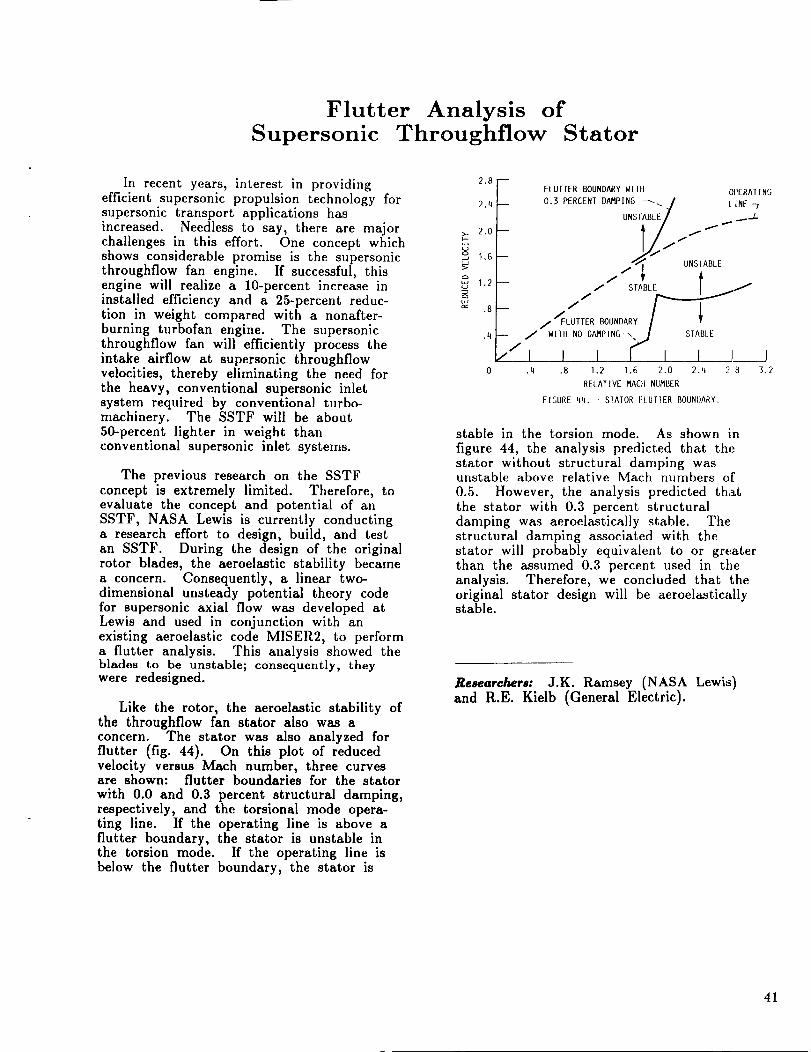
Flutter Analysis ofSupersonic Throughflow Stator
In recent years, interest in providingefficient supersonic propulsion technology forsupersonic transport applications has
increased. Needless to say, there are majorchallenges in this effort. One concept whichshows considerable promise is the supersonicthroughflow fan engine. If successful, thisengine will realize a 10-percent increase ininstalled efficiency and a 25-percent reduc-tion in weight compared with a nonafter-burning turbofan engine. The supersonicthroughflow fan will efficiently process theintake airflow at supersonic throughflowvelocities, thereby eliminating the need forthe heavy, conventional supersonic inletsystem required by conventional turbo-machinery. The SSTF will be about50-percent lighter in weight thanconventional supersonic inlet systems.
The previous research on the SSTFconcept is extremely limited. Therefore, toevaluate the concept and potential of anSSTF, NASA Lewis is currently conductinga research effort to design, build, and testan SSTF. During the design of the originalrotor blades, the aeroelastic stability becamea concern. Consequently, a linear two-dimensional unsteady potential theory codefor supersonic axial flow was developed atLewis and used in conjunction with anexisting aeroelastic code MISER2, to performa flutter analysis. This analysis showed theblades to be unstable; consequently, theywere redesigned.
Like the rotor, the aeroelastic stability ofthe throughflow fan stator also was aconcern. The stator was also analyzed for
flutter (fig. 44). On this plot of reducedvelocity versus Mach number, three curvesare shown: flutter boundaries for the stator
with 0.0 and 0.3 percent structural damping,respectively, and the torsional mode opera-ting line. If the operating line is above aflutter boundary, the stator is unstable inthe torsion mode. If the operating line isbelow the flutter boundary, the stator is
2.8
2.q
2.0
1.6
,,:, 1.2,.u
.4
m
m
-- /
//I.q
FLUTTER BOUNDARY WIDI OPERATING
0.3 PERCENT D_PING _j LINE
UNSTABLE/ _
11_. UNS I ABI E
/'_FLUITER BOUNDARY
WIIII NO D_PING_,j_ ST_LE
I I I I I 1 I.8 1.2 1.6 2.0 2.q 28 3.2
RELATIVE _CH NUMBER
FIGURE 4q. - SIAIOR ELUT1ER BOUNDARY.
stable in the torsion mode. As shown in
figure 44, the analysis predicted that thestator without structural damping wasunstable above relative Mach numbers of
0.5. However, the analysis predicted thatthe stator with 0.3 percent structuraldamping was aeroelastically stable. The
structural damping associated with thestator will probably equivalent to or greaterthan the assumed 0.3 percent used in theanalysis. Therefore, we concluded that theoriginal stator design will be aeroelasticallystable.
Researchers: J.K. Ramsey (NASA Lewi:s)and R.E. Kielb (General Electric).
41

Appendix- Researchers
Babula, M .......... The University Of Toledo, Toledo, Ohio
Brown, G.V ....... NASA Lewis Research Center, Cleveland, OhioChung, C.L ........ Carnegie-Mellon University, Pittsburgh, PennsylvaniaCoirier, W.J ........ NASA Lewis Research Center, Cleveland, OhioDesa, S ........... Carnegie-Mellon University, Pittsburgh, PennsylvaniaDiRusso, E ......... NASA Lewis Research Center, Cleveland, OhioFinlay, C.T ........ Sverdrup Technology, Inc., Lewis Research Center
Group, Brook Park, OhioFleming, D.P ........ NASA Lewis Research Center, Cleveland, OhioGasparini, D ........ Case Western Reserve University, Cleveland, OhioGrodsinsky, C.M ...... NASA Lewis Research Center, Cleveland, OhioHuckelbridge, A.A ..... Case Western Reserve University, Cleveland, OhioHuff, D.L .......... NASA Lewis Research Center, Cleveland, OhioJanetzke, D.C ....... NASA Lewis Research Center, Cleveland, OhioKascak, A.F ........ U.S. Army Aviation Research and Technology Activity
- AVSCOM, NASA Lewis Research Center, Cleveland, OhioKielb, R.E ......... General Electric Company, Cincinnati, OhioKikuchi, N ......... University of Michigan, Ann Arbor, MichiganKiraly, L.J ......... NASA Lewis Research Center, Cleveland, OhioLakatos, T.F ........ NASA Lewis Research Center, Cleveland, OhioLawrence, C ........ NASA Lewis Research Center, Cleveland, OhioLin, N.J .......... Case Western Reserve University, Cleveland, OhioLin, R.R .......... Texas A&M University, College Station, TexasMeyn, E.H ......... NASA Lewis Research Center, Cleveland, OhioMiller, J.H ......... Sverdrup Technology, Inc., Lewis Research Center
Group, Brook Park, OhioMontague, G.T ...... Sverdrup Technology, Inc., Lewis Research Center
Group, Brook Park, OhioMullen, R.L ........ Case Western Reserve University, Cleveland, OhioMurthy, D.V ........ The University of Toledo, Resident Research Associate at
NASA Lewis Research Center, Cleveland, OhioNonami, K ......... Chiba University, Chiba, JapanPalazzolo, 'A.D ....... Texas A&M University, College Station, TexasPosta, S.J ......... NASA Lewis Research Center, Cleveland, OhioQuinn, R.D ........ Case Western Reserve University, Cleveland, OhioRadii, K.C ......... U.S. Army Aviation Research and Technology Activity
AVSCOM, NASA Lewis Research Center, Cleveland, Ohio
Ramsey, J.K ........ NASA Lewis Research Center, Cleveland, OhioReddy, T.S.R ....... The University of Toledo, Resident Research Associate at
NASA Lewis Research Center, Cleveland, OhioRohn, D.A ......... NASA Lewis Research Center, Cleveland, Ohio
Ropchock, J.J ....... NASA Lewis Research Center, Cleveland, OhioSmolinski, P.J ....... Institute for Computational Mechanics in Propulsion
(ICOMP), NASA Lewis Research Center, Cleveland, OhioStefko, G.L ......... NASA Lewis Research Center, Cleveland, OhioSteinetz, B.M ....... NASA Lewis Research Center, Cleveland, OhioTaylor, J.E ......... University of Michigan, Ann Arbor, Michigan
Tong, M .......... Sverdrup Technology, Inc., Lewis Research CenterGroup, Brook Park, Ohio
Ulbrich, H ......... National Research Council (NRC) NASA Resident ResearchAssociate at Lewis Research Center during 1989. Presentaddress: Technical University of Braunschweig, Braunschweig,Federal Republic of Germany.
Watson, J.W ........ Sparta, Inc., Huntsville, Alabama
42
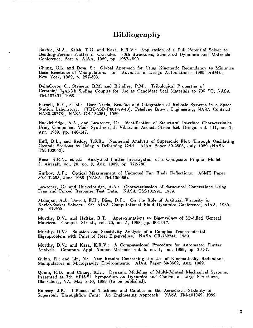
Bibliography
Bakhle, M.A., Keith, T.G. and Kaza, K.R.V.: Application of a Full Potential Solver toBending-Torsion Flutter in Cascades. 30th Structures, Structural Dynamics and Material_3Conference, Part 4, AIAA, 1989, pp. 1982-1990.
Chung, C.L. and Desa, S.: Global Approach for Using Kinematic Redundancy to MinimizeBase Reactions of Manipulators. In: Advances in Design Automation - 1989; ASME,New York, 1989, p. 297-303.
DellaCorte, C., Steinetz, B.M. and Brindley, P.M.: Tribological Properties ofCeramic/Ti3AI-Nb Sliding Couples for Use as Candidate Seal Materials to 700 *C, NASATM-102401, 1989.
Farnell, K.E., et al.: User Needs, Benefits and Integration of Robotic Systems in a SpaceStation Laboratory. (TBE-SSD-P601-89-40), Teledyne Brown Engineering; NASA ContractNAS3-25278), NASA CR-182261, 1989.
Hucklebridge, A.A.; and Lawrence, C.: Identification of Structural Interface CharacteristicsUsing Component Mode Synthesis, J. Vibration Acoust. Stress Rel. Design, vol. 111, no. 2,Apr. 1989, pp. 140-147.
Huff, D.L.; and Reddy, T.S.R.: Numerical Analysis of Supersonic Flow Through OscillatingCascade Sections by Using a Deforming Grid. AIAA Paper 89-2805, July 1989 (NASATM-102053).
Kaza, K.R.V., et al.: Analytical Flutter Investigation of a Composite Propfan Model,J. Aircraft, vol. 26, no. 8, Aug. 1989, pp. 772-780.
Kurkov, A.P.: Optical Measurement of Unducted Fan Blade Deflections. ASME Paper89-GT-298, June 1989 (NASA TM-100966).
Lawrence, C.; and Huckelbridge, A.A.: Characterization of Structural Connections UsingFree and Forced Response Test Data. NASA TM-101991, 1989.
Mahajan, A.J.; Dowell, E.H.; Bliss, D.B.: On the Role of Artificial Viscosity inNavier-Stokes Solvers. 9th AIAA Computational Fluid Dynamics Conference, AIAA, 1989,pp. 197-202.
Murthy, D.V.; and Haftka, R.T.: Approximations to Eigenvalues of Modified GeneralMatrices. Comput. Struct., vol. 29, no. 5, 1988, pp. 903-917.
Murthy, D.V.: Solution and Sensitivity Analysis of a Complex TranscendentalEigenproblem with Pairs of Real Eigenvalues. NASA CR-182241, 1989.
Murthy, D.V.; and Kaza, K.R.V.: A Computational Procedure for Automated FlutterAnalysis. Commun. Appl. Numer. Methods, vol. 5, no. 1, Jan. 1989, pp. 29-37.
Quinn, R.; and Lin, N.: New Results Concerning the Use of Kinematically RedundantManipulators in Microgravity Environments. AIAA Paper 89-3562, Aug. 1989.
Quinn, R.D.; and Chang, R.K.: Dynamic Modeling of Multi-Jointed Mechanical Systems.Presented at 7th VPI&SU Symposium on Dynamics and Control of Large Structures,Blacksburg, VA, May 8-10, 1989 (to be published).
Ramsey_ J.K.: Influence of Thickness and Camber on the Aeroelastic Stability ofSupersonic Throughflow Fans: An Engineering Approach. NASA TM-101949, 1989.
43
Reddy, T.; and Mehmed, O.: Aeroelastic Analysis of Propfan Blades With a Semi-empirical Dynamic Stall Model. AIAA-89-2695, July 1989.
Savage, M., et al.: Computerized Life and Reliability Modeling for TurbopropTransmissions. J. Propulsion Power, vol. 5, no. 5, Sept.-Oct. 1988,pp. 610-614.
Steinetz, B.M.; DellaCorte, C.; and Sirocky, P.J.: On the Development of Hypersonic
Engine Seals. NASA TP-2854, 1988.
Walton, J.; Lee, C.; and Martin, M.: High Speed Balancing Applied to the T700 Engine.
MTI-87TR56, Mechanical Technology, Inc.; NASA Contract NAS3-23929) NASA-180899, 1989).
44
Report Documentation PageNatronal Aeronautics andSpace Administration
1. Report No. 2. Government Accession No. 3. Rectp_ent's Catalog No.
NASA TM-102488
4. Title and Subtitle
Structural Dynamics Branch Research and Accomplishments for FY 1989
7 Author(s)
Performing Organization Name and Address
National Aeronautics and Space AdministrationLewis Research Center
Cleveland, Ohio 44135-3191
12. Sponsoring Agency Name and Address
National Aeronautics and Space Administration
Washington, D.C. 20546-0001
5. Report Date
July 1990
6 Performmg Organization Code
8. Performing Organization Report No.
E-5279
10 Work Unit No.
505-63-1B
11 Contract or Grant No.
13. Type of Report and Period Covered
Technical Memorandum
14 Sponsoring Agency Code
15. Supplementary Notes
16. Abstract ,
This publication contains.a-collection of fiscal year 1989 research highlights from the Structural Dynamics Branch
at NASA Lewis Research Center i Highlights from the branch's major work areas--Aeroelasticity, Vibration
Control, Dynamic Systems, and Computational Structural Methods--are included in the report as well as a listingof the fiscal year 1989 branch publications.
17. Key Words (Suggested by Author(s))
AeroelasticityVibration control
Dynamic systems
18. DIstrtbution Statement
Unclassified - Unlimited
Subject Category 39
19. Secunty Classlf. (of this report) 20. Security Classlf. (of this page) 21. No. of pages
Unclassified Unclassified 50
NASAFORM1626OCT86 *For sale by the National Technbcal Informatton Service, Spnngfleld, VLrg_n_a22161
22. Price*
A03