Structural Durability Analysis of a Powertrain mounting bracket · 2013-11-15 · Mahindra &...
16
1 Copyright © 2012 Mahindra & Mahindra Ltd. All rights reserved. Structural Durability Analysis of a Powertrain mounting bracket
Transcript of Structural Durability Analysis of a Powertrain mounting bracket · 2013-11-15 · Mahindra &...
1Copyright © 2012 Mahindra & Mahindra Ltd. All rights reserved.
Structural Durability Analysis of a Powertrain mounting bracket
2
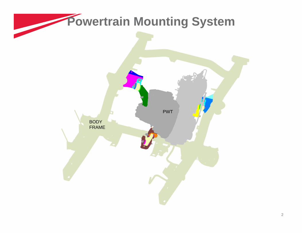
PWT
BODY FRAME
Powertrain Mounting System
3
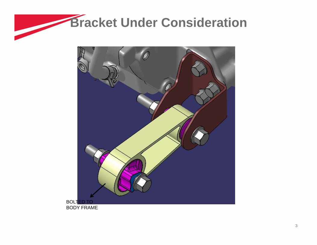
BOLTED TO BODY FRAME
Bracket Under Consideration
4
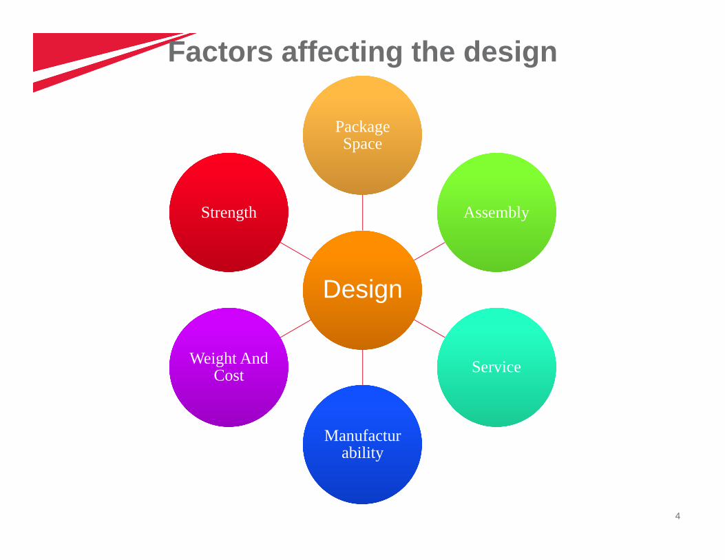
Factors affecting the design
DesignDesign
Package Space
Package Space
AssemblyAssembly
ServiceService
Manufacturability
Manufacturability
Weight And Cost
Weight And Cost
StrengthStrength
5
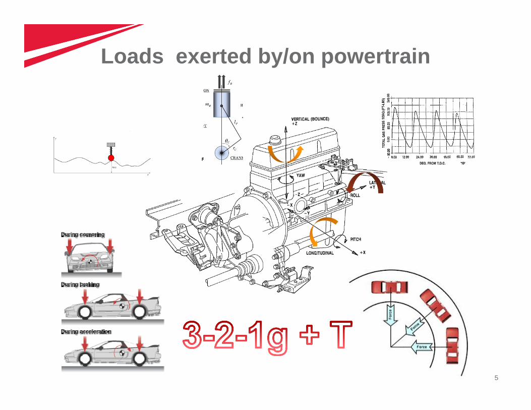
Loads exerted by/on powertrain
6
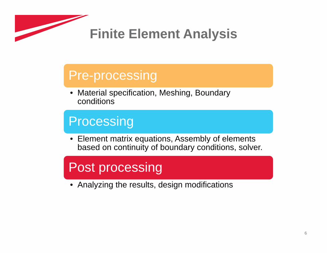
Finite Element Analysis
Pre-processing• Material specification, Meshing, Boundary
conditions
Processing• Element matrix equations, Assembly of elements
based on continuity of boundary conditions, solver.
Post processing• Analyzing the results, design modifications
7
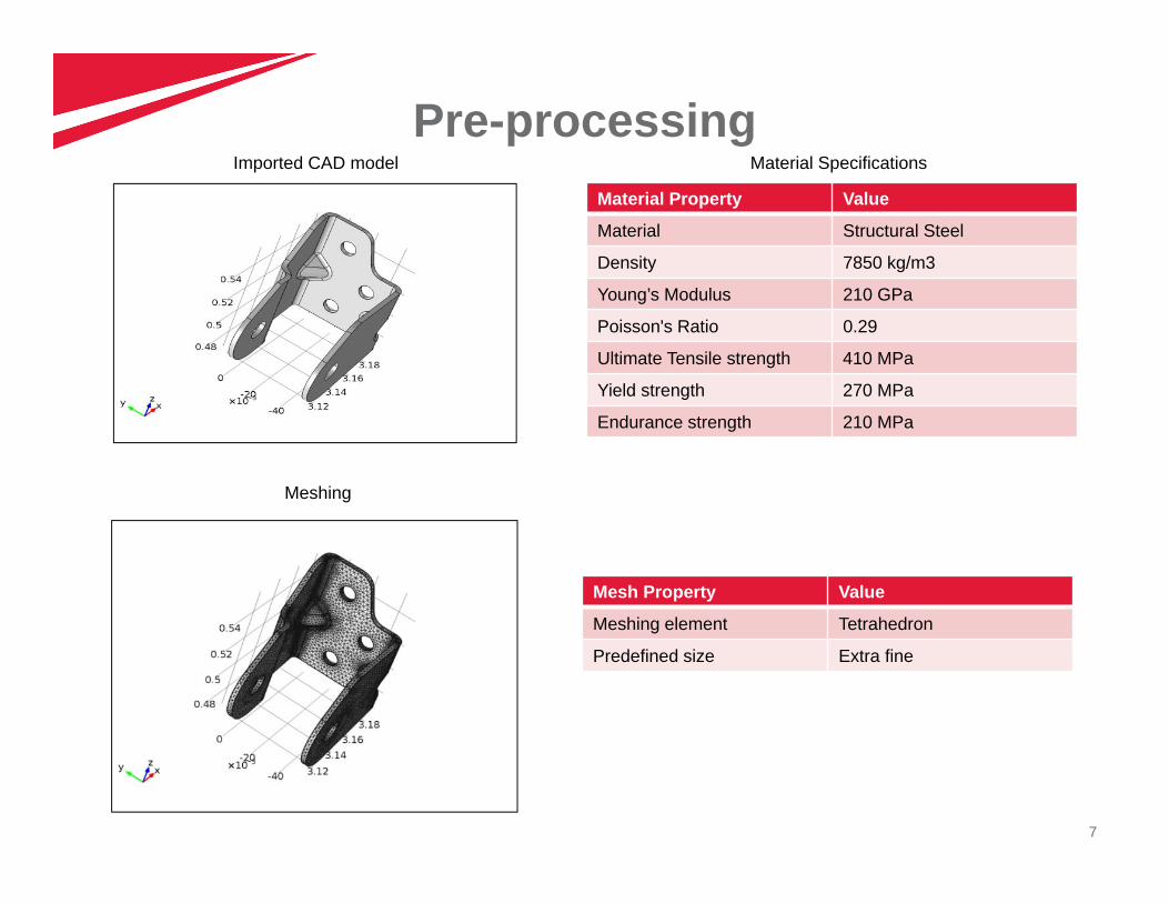
Pre-processingMaterial Property Value
Material Structural Steel
Density 7850 kg/m3
Young’s Modulus 210 GPa
Poisson's Ratio 0.29
Ultimate Tensile strength 410 MPa
Yield strength 270 MPa
Endurance strength 210 MPa
Material Specifications
Meshing
Mesh Property Value
Meshing element Tetrahedron
Predefined size Extra fine
Imported CAD model
8
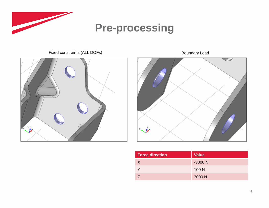
Pre-processing
Force direction Value
X -3000 N
Y 100 N
Z 3000 N
Fixed constraints (ALL DOFs) Boundary Load
9
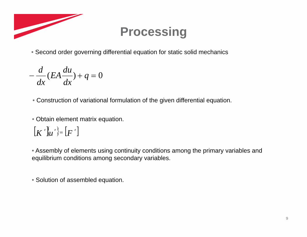
Processing• Second order governing differential equation for static solid mechanics
0)( qdxduEA
dxd
• Construction of variational formulation of the given differential equation.
• Obtain element matrix equation.
FuK eee
• Assembly of elements using continuity conditions among the primary variables and equilibrium conditions among secondary variables.
• Solution of assembled equation.
10
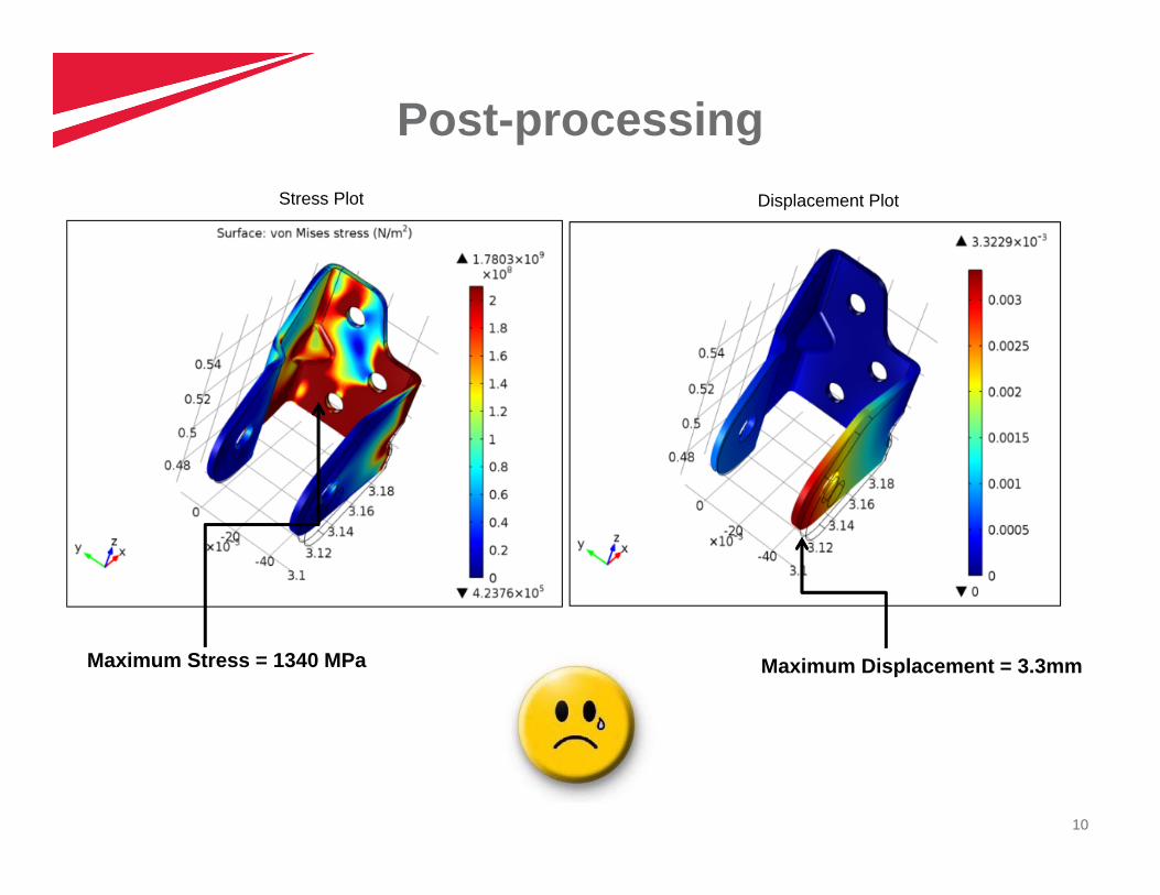
Post-processingStress Plot Displacement Plot
Maximum Stress = 1340 MPa Maximum Displacement = 3.3mm
11
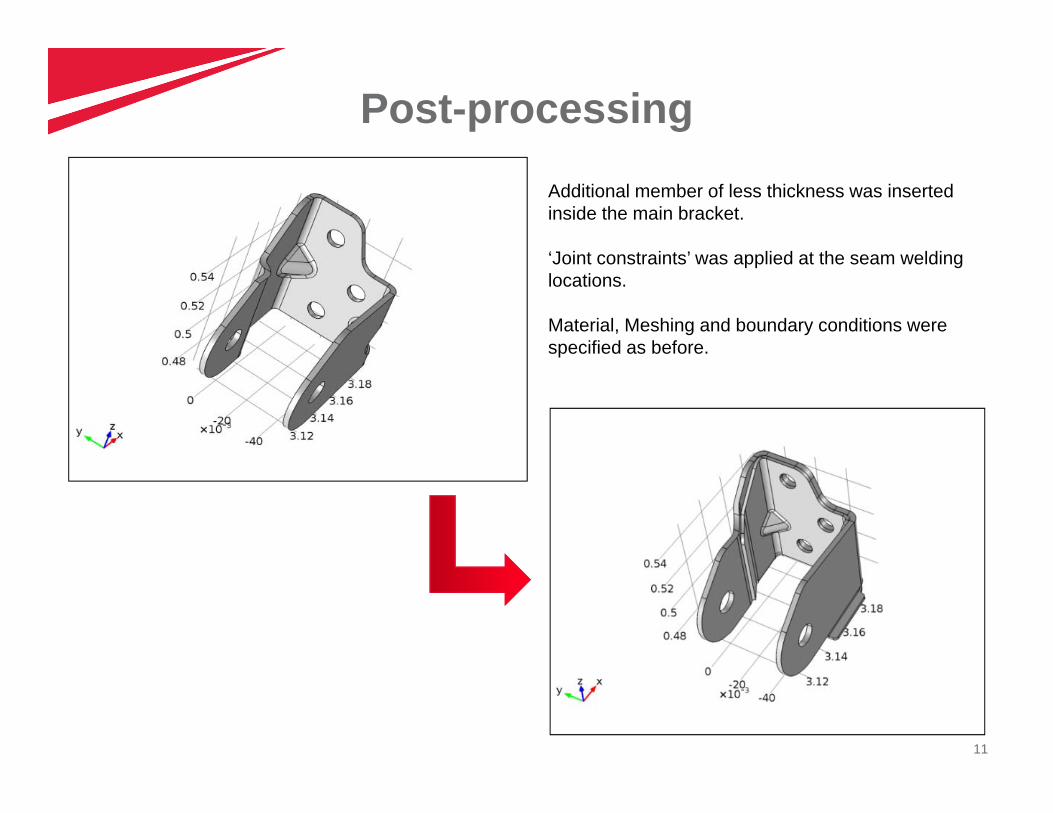
Post-processing
Additional member of less thickness was inserted inside the main bracket.
‘Joint constraints’ was applied at the seam welding locations.
Material, Meshing and boundary conditions were specified as before.
12
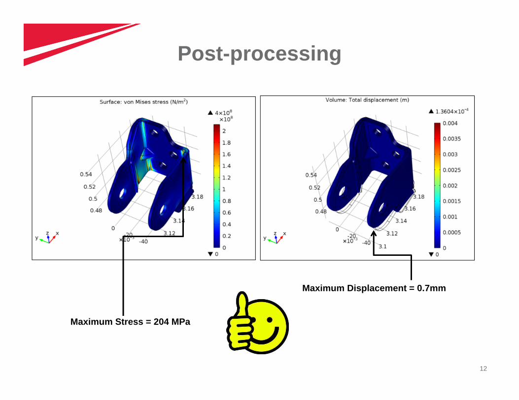
Post-processing
Maximum Stress = 204 MPa
Maximum Displacement = 0.7mm
13
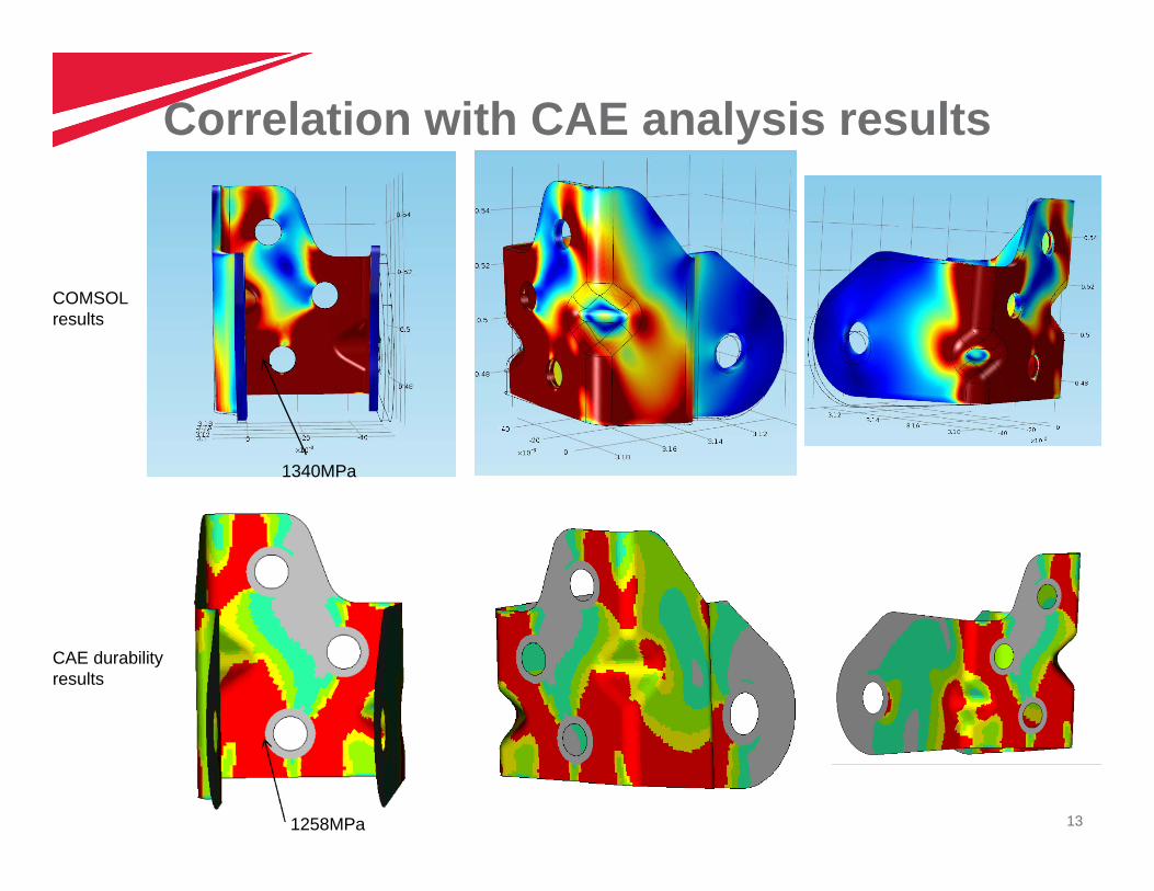
Correlation with CAE analysis results
COMSOL results
CAE durability results
1258MPa
1340MPa
14
Conclusion Used COMSOL multiphysics to perform the structural analysis of powertrain
mounting bracket.
Optimized the bracket design by using the obtained results thereby reducingthe number of CAE iterations and thus save time.
The way forward…
Using multiphysics to perform the thermal, frequency and fatigue life analysisfor the bracket.
15
DisclaimerMahindra & Mahindra herein referred to as M&M, and its subsidiary companies provide a wide array of presentations and reports,with the contributions of various professionals. These presentations and reports are for informational purposes and private circulationonly and do not constitute an offer to buy or sell any securities mentioned therein. They do not purport to be a complete description ofthe markets conditions or developments referred to in the material. While utmost care has been taken in preparing the above, weclaim no responsibility for their accuracy. We shall not be liable for any direct or indirect losses arising from the use thereof and theviewers are requested to use the information contained herein at their own risk. These presentations and reports should not bereproduced, re-circulated, published in any media, website or otherwise, in any form or manner, in part or as a whole, without theexpress consent in writing of M&M or its subsidiaries. Any unauthorized use, disclosure or public dissemination of informationcontained herein is prohibited. Unless specifically noted, M&M or any of its subsidiary companies is not responsible for the content ofthese presentations and/or the opinions of the presenters. Individual situations and local practices and standards may vary, soviewers and others utilizing information contained within a presentation are free to adopt differing standards and approaches as theysee fit. You may not repackage or sell the presentation. Products and names mentioned in materials or presentations are the propertyof their respective owners and the mention of them does not constitute an endorsement by M&M or its subsidiary companies.Information contained in a presentation hosted or promoted by M&M is provided “as is” without warranty of any kind, either expressedor implied, including any warranty of merchantability or fitness for a particular purpose. M&M or its subsidiary companies assume noliability or responsibility for the contents of a presentation or the opinions expressed by the presenters. All expressions of opinion aresubject to change without notice.
Copyright © 2012 Mahindra & Mahindra Ltd. All rights reserved.
Thank youVisit us at www.mahindra.com

16


![[3879] – 11 - Savitribai Phule Pune University3879] – 11 6. Case study. CASE Mahindra & Mahindra Mahindra & Mahindra (M & M) is a major player in the tractor and certain segments](https://static.fdocuments.us/doc/165x107/5af6b71a7f8b9a190c901cb2/3879-11-savitribai-phule-pune-3879-11-6-case-study-case-mahindra.jpg)