Structural Design of a Horizontal-Axis Tidal Current ... · PDF fileStructural Design of a...
14
NREL is a national laboratory of the U.S. Department of Energy, Office of Energy Efficiency & Renewable Energy, operated by the Alliance for Sustainable Energy, LLC. Contract No. DE-AC36-08GO28308 Structural Design of a Horizontal-Axis Tidal Current Turbine Composite Blade G.S. Bir, M.J. Lawson, and Y. Li Presented at the ASME 30 th International Conference on Ocean, Offshore, and Arctic Engineering Rotterdam, The Netherlands June 19-24, 2011 Conference Paper NREL/CP-5000-50658 October 2011
Transcript of Structural Design of a Horizontal-Axis Tidal Current ... · PDF fileStructural Design of a...

NREL is a national laboratory of the U.S. Department of Energy, Office of Energy Efficiency & Renewable Energy, operated by the Alliance for Sustainable Energy, LLC.
Contract No. DE-AC36-08GO28308
Structural Design of a Horizontal-Axis Tidal Current Turbine Composite Blade G.S. Bir, M.J. Lawson, and Y. Li
Presented at the ASME 30th International Conference on Ocean, Offshore, and Arctic Engineering Rotterdam, The Netherlands June 19-24, 2011
Conference Paper NREL/CP-5000-50658 October 2011
NOTICE
The submitted manuscript has been offered by an employee of the Alliance for Sustainable Energy, LLC (Alliance), a contractor of the US Government under Contract No. DE-AC36-08GO28308. Accordingly, the US Government and Alliance retain a nonexclusive royalty-free license to publish or reproduce the published form of this contribution, or allow others to do so, for US Government purposes.
This report was prepared as an account of work sponsored by an agency of the United States government. Neither the United States government nor any agency thereof, nor any of their employees, makes any warranty, express or implied, or assumes any legal liability or responsibility for the accuracy, completeness, or usefulness of any information, apparatus, product, or process disclosed, or represents that its use would not infringe privately owned rights. Reference herein to any specific commercial product, process, or service by trade name, trademark, manufacturer, or otherwise does not necessarily constitute or imply its endorsement, recommendation, or favoring by the United States government or any agency thereof. The views and opinions of authors expressed herein do not necessarily state or reflect those of the United States government or any agency thereof.
Available electronically at http://www.osti.gov/bridge
Available for a processing fee to U.S. Department of Energy and its contractors, in paper, from:
U.S. Department of Energy Office of Scientific and Technical Information
P.O. Box 62 Oak Ridge, TN 37831-0062 phone: 865.576.8401 fax: 865.576.5728 email: mailto:[email protected]
Available for sale to the public, in paper, from:
U.S. Department of Commerce National Technical Information Service 5285 Port Royal Road Springfield, VA 22161 phone: 800.553.6847 fax: 703.605.6900 email: [email protected] online ordering: http://www.ntis.gov/help/ordermethods.aspx
Cover Photos: (left to right) PIX 16416, PIX 17423, PIX 16560, PIX 17613, PIX 17436, PIX 17721
Printed on paper containing at least 50% wastepaper, including 10% post consumer waste.

1
STRUCTURAL DESIGN OF A HORIZONTAL-AXIS TIDAL CURRENT TURBINE COMPOSITE BLADE
Gunjit S. Bir National Renewable Energy
Laboratory Golden, CO, USA
Email: [email protected]
Michael J. Lawson National Renewable Energy
Laboratory Golden, CO, USA
Email: [email protected]
Ye Li National Renewable Energy
Laboratory Golden, CO, USA
Email: [email protected]
ABSTRACT This paper describes the structural design of a tidal turbine
composite blade. The structural design is preceded by two steps: hydrodynamic design and determination of extreme loads. The hydrodynamic design provides the chord and twist distributions along the blade length that result in optimal performance of the tidal turbine over its lifetime. The extreme loads, i.e. the extreme flap and edgewise loads that the blade would likely encounter over its lifetime, are associated with extreme tidal flow conditions and are obtained using a computational fluid dynamics (CFD) software. Given the blade external shape and the extreme loads, we use a laminate-theory-based structural design to determine the optimal layout of composite laminas such that the ultimate-strength and buckling-resistance criteria are satisfied at all points in the blade. The structural design approach allows for arbitrary specification of the chord, twist, and airfoil geometry along the blade and an arbitrary number of shear webs. In addition, certain fabrication criteria are imposed, for example, each composite laminate must be an integral multiple of its constituent ply thickness. In the present effort, the structural design uses only static extreme loads; dynamic-loads-based fatigue design will be addressed in the future. Following the blade design, we compute the distributed structural properties, i.e. flap stiffness, edgewise stiffness, torsion stiffness, mass, moments of inertia, elastic-axis offset, and center-of-mass offset along the blade. Such properties are required by hydro-elastic codes to model the tidal current turbine and to perform modal, stability, loads, and response analyses.
INTRODUCTION Extraction of energy from tidal currents, an untapped
renewable resource so far, is gaining increased attention. Tidal currents are an attractive source of renewable energy due to their predictability and high energy density. Recently, numerous technologies have been developed to convert the energy available within tidal currents into electrical power [1].
Horizontal-axis tidal turbines (HATTs) are perhaps the most mature and promising of the technologies and several companies (e.g. Marine Current Turbine, Verdant Power, and OpenHydro) have developed HATT prototypes that are currently undergoing testing. Nevertheless, as blade failures on a number of prototype devices have demonstrated, the ability to design HATT blades to withstand the expected hydrodynamic loads is critical. A HATT basically works on the same principle as does a horizontal-axis wind turbine. The HATT rotor blades convert the tidal current kinetic energy into the shaft mechanical energy and a generator converts this mechanical energy into electricity. Figure 1 shows a few examples of HATT configurations. These configurations differ in the type of support structure used for the turbine rotor. Fraenkel [1] discusses pros and cons of each configuration.
FIGURE 1. EXAMPLES OF HORIZONTAL-AXIS TIDAL
CURRENT TURBINE (HATT) CONFIGURATIONS. EACH CONFIGURATION IS BEST SUITED FOR A PARTICULAR SEA
DEPTH RANGE [1].
Irrespective of which configuration is used, the rotor blade is the key component that extracts energy from the tide and primarily dictates the performance, loads, and dynamics of the whole turbine system. Therefore, an efficient blade design is critical to the success of the HATT.
2
This paper focuses on the structural design of a tidal turbine composite blade. The structural design is preceded by two steps: hydrodynamic design and determination of extreme loads. The hydrodynamic design, discussed in the companion paper [2], provides the blade external shape, i.e. the chord and twist distributions along the blade, which result in optimal performance of the tidal turbine over its lifetime. The extreme loads, i.e. the extreme flap and edgewise loads that the blade would likely encounter over its lifetime, are associated with extreme tidal flow conditions and are determined using a computational fluid dynamics (CFD) software. Given the blade external shape and the extreme loads, we use a laminate-theory-based structural design to determine the optimal layout of composite laminas such that the ultimate-strength and buckling-resistance criteria are satisfied at all points in the blade. This structural design approach allows for arbitrary specification of the chord, twist, and airfoil geometry along the blade and an arbitrary number of shear webs. In addition, certain fabrication criteria are imposed, for example, each composite laminate must be an integral multiple of its constituent ply thickness. In the present effort, the structural design uses only static extreme loads; dynamic loads-based fatigue design is not addressed. Following the blade design, we compute the distributed structural properties, i.e flap stiffness, edgewise stiffness, torsion stiffness, mass, moments of inertia, elastic-axis offset, and center-of-mass offset along the blade. Such properties are required by hydro-elastic codes to model the tidal current turbine and to perform modal, stability, loads, and response analyses.
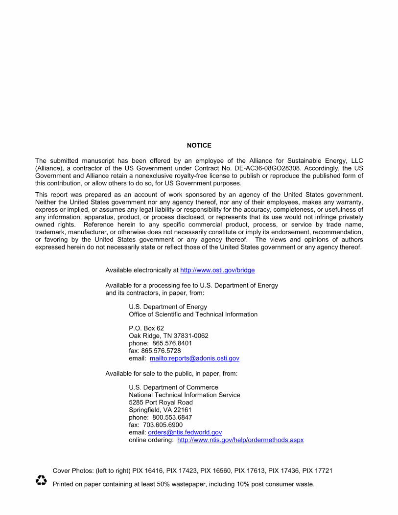
THE TIDAL CURRENT TURBINE DESCRIPTION This paper considers a hypothetical monopole-supported
550 kilowatt (kW) turbine shown in Figure 2; it is intended for deployment at the Northern Admiralty Inlet of Puget Sound. Table 1 lists the key design and operating specifications for the turbine.
TABLE 1. TURBINE SPECIFICATIONS
Rated power 550 kW Number of rotors 2 Rotor diameter 20 m
Number of rotor blades 2
Control type Variable speed, variable pitch
Hub diameter 2 m Maximum rotor speed 11.5 rpm
Normal flow speed range 0.5–3.0 m/s Hub height 18 m
Primary blade airfoil NACA 631-424 Water depth 33 m
The turbine has two 20-meter (m) diameter rotors. Each rotor has two blades and is mounted on a 2-m diameter hub. The blade design is optimized for a variable speed, variable pitch (VSVP) operation. A NACA 631-424 airfoil defines the primary
shape of the turbine blade; this airfoil was selected because it provides a relatively large minimum pressure coefficient and makes the blade resistant to cavitation. Also, NACA 63 series airfoils delay stall and are less sensitive to leading edge roughness than NACA 4 and 5 series airfoils. We assume a circular cross-section over the blade root length that is well suited to variable- pitch mechanism. The circular section transitions to the NACA 631-424 airfoil shape at 20% of the blade span. It may be possible to improve the performance of the blade (i.e. increase power generation) by using different airfoil shapes over the blade length. We will explore this possibility in the future.
FIGURE 2A. SCHEMATIC OF THE MONOPOLE-SUPPORTED TIDAL CURRENT TURBINE. THE MONOPOLE IS DUG INTO
THE SEABED AND THE TWIN ROTOR ASSEMBLY CAN SLIDE UP AND DOWN THE VERTICAL SHAFT.
FIGURE 2B. EACH ROTOR HAS TWO BLADES. THE BLADES
SHED STRONG TIP VORTICES, AS SHOWN IN THIS COMPUTATIONAL FLUID DYNAMICS (CFD) SIMULATION,
AND SIGNIFICANTLY INFLUENCE THE BLADE LOADS.
3
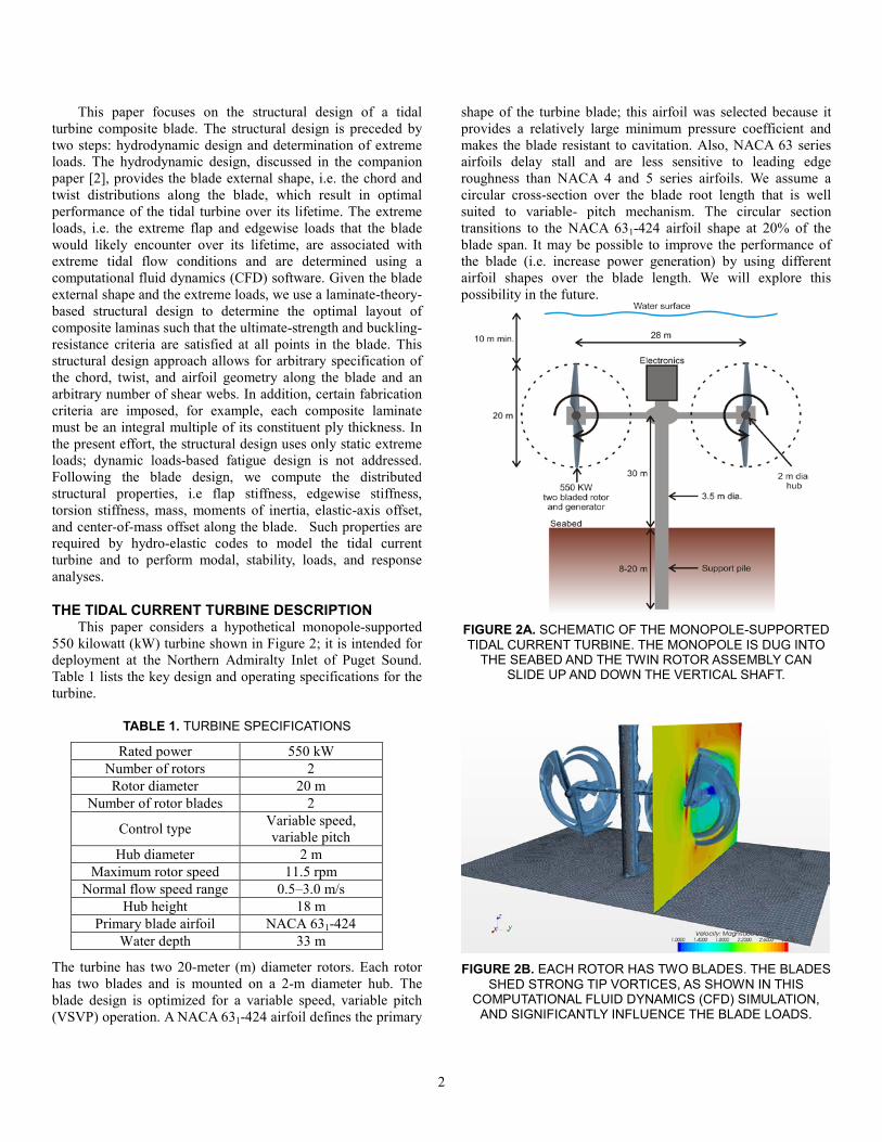
DESIGN APPROACH Figure 3 summarizes the hydro-structural design of the
HATT blade and computation of its structural properties. The green boxes identify the three main steps: hydrodynamic design, computation of extreme loads, and structural design. The following sections describe these steps.
HYDRODYNAMIC BLADEDESIGN (using HAWT_Opt)
EXTREME LOADS COMPUTATION( using CFD simulations)
STRUCTURAL BLADE DESIGN(based on ultimate and
buckling strength criteria)
Inputs: rotor diameter, tidal current conditions,
airfoils geometries& aerodynamic coefficients
Composite material properties, material & load
factors of safety, blade fabrication constraints
Extreme operating conditions
Blade external shape: chord & twist distribution along the
blade
Optimal composite laminates layup inside the
blade
Structural properties along the blade length Structural Analysis
FIGURE 3. STEPS USED IN THE AERO-STRUCTURAL
BLADE DESIGN
HYDRODYNAMIC DESIGN The turbine blade is designed for a hypothetical 550 kW
turbine intended for deployment at the Northern Admiralty Inlet of Puget Sound. An acoustic Doppler current profiler survey at this site [3] shows the mean water velocity is approximately 1 m/s, although velocities as high as 3 m/s occur during the tidal cycle. Table 1 presents the turbine’s specifications. The turbine has a 20-m diameter rotor comprised of a 2-m diameter hub and two blades. The blade design is optimized for a VSVP turbine that has a maximum rotation rate of 11.5 revolutions per minute (rpm).
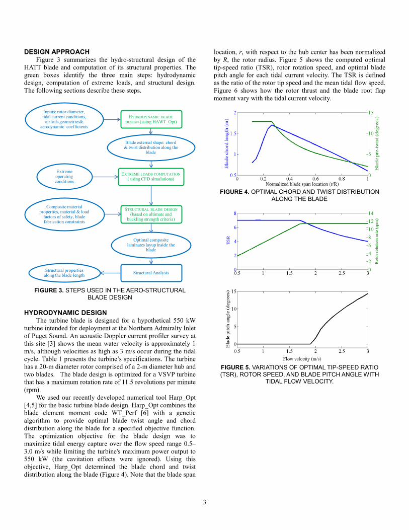
We used our recently developed numerical tool Harp_Opt [4,5] for the basic turbine blade design. Harp_Opt combines the blade element moment code WT_Perf [6] with a genetic algorithm to provide optimal blade twist angle and chord distribution along the blade for a specified objective function. The optimization objective for the blade design was to maximize tidal energy capture over the flow speed range 0.5–3.0 m/s while limiting the turbine's maximum power output to 550 kW (the cavitation effects were ignored). Using this objective, Harp_Opt determined the blade chord and twist distribution along the blade (Figure 4). Note that the blade span
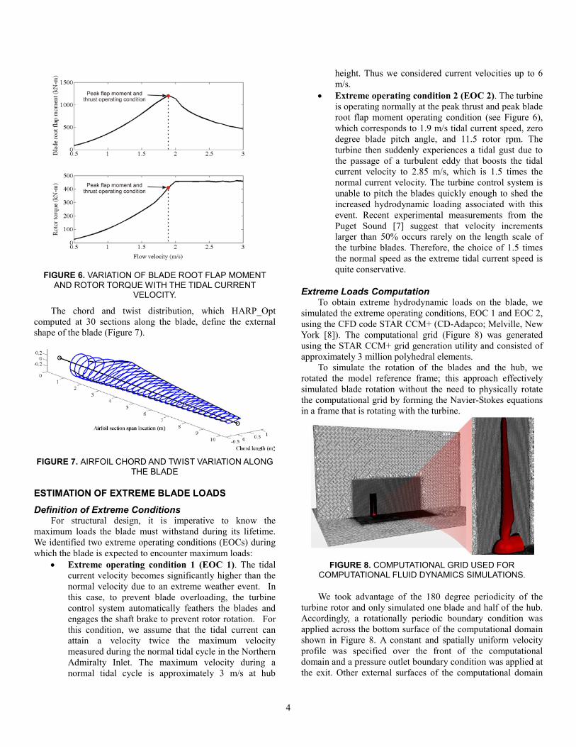
location, r, with respect to the hub center has been normalized by R, the rotor radius. Figure 5 shows the computed optimal tip-speed ratio (TSR), rotor rotation speed, and optimal blade pitch angle for each tidal current velocity. The TSR is defined as the ratio of the rotor tip speed and the mean tidal flow speed. Figure 6 shows how the rotor thrust and the blade root flap moment vary with the tidal current velocity.
FIGURE 4. OPTIMAL CHORD AND TWIST DISTRIBUTION ALONG THE BLADE
FIGURE 5. VARIATIONS OF OPTIMAL TIP-SPEED RATIO (TSR), ROTOR SPEED, AND BLADE PITCH ANGLE WITH
TIDAL FLOW VELOCITY.
4
FIGURE 6. VARIATION OF BLADE ROOT FLAP MOMENT
AND ROTOR TORQUE WITH THE TIDAL CURRENT VELOCITY.
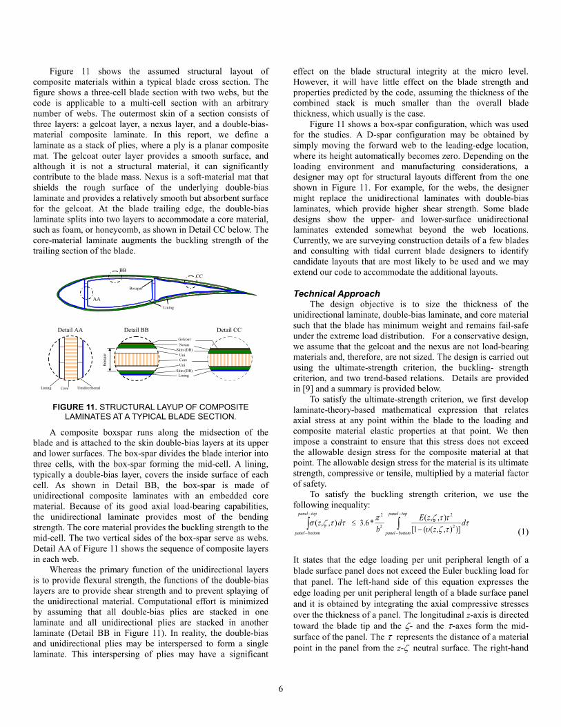
The chord and twist distribution, which HARP_Opt computed at 30 sections along the blade, define the external shape of the blade (Figure 7).
FIGURE 7. AIRFOIL CHORD AND TWIST VARIATION ALONG
THE BLADE
ESTIMATION OF EXTREME BLADE LOADS
Definition of Extreme Conditions For structural design, it is imperative to know the
maximum loads the blade must withstand during its lifetime. We identified two extreme operating conditions (EOCs) during which the blade is expected to encounter maximum loads:
• Extreme operating condition 1 (EOC 1). The tidal current velocity becomes significantly higher than the normal velocity due to an extreme weather event. In this case, to prevent blade overloading, the turbine control system automatically feathers the blades and engages the shaft brake to prevent rotor rotation. For this condition, we assume that the tidal current can attain a velocity twice the maximum velocity measured during the normal tidal cycle in the Northern Admiralty Inlet. The maximum velocity during a normal tidal cycle is approximately 3 m/s at hub
height. Thus we considered current velocities up to 6 m/s.
• Extreme operating condition 2 (EOC 2). The turbine is operating normally at the peak thrust and peak blade root flap moment operating condition (see Figure 6), which corresponds to 1.9 m/s tidal current speed, zero degree blade pitch angle, and 11.5 rotor rpm. The turbine then suddenly experiences a tidal gust due to the passage of a turbulent eddy that boosts the tidal current velocity to 2.85 m/s, which is 1.5 times the normal current velocity. The turbine control system is unable to pitch the blades quickly enough to shed the increased hydrodynamic loading associated with this event. Recent experimental measurements from the Puget Sound [7] suggest that velocity increments larger than 50% occurs rarely on the length scale of the turbine blades. Therefore, the choice of 1.5 times the normal speed as the extreme tidal current speed is quite conservative.
Extreme Loads Computation To obtain extreme hydrodynamic loads on the blade, we
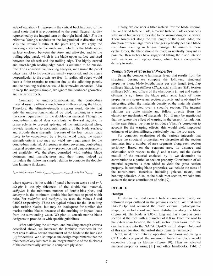
simulated the extreme operating conditions, EOC 1 and EOC 2, using the CFD code STAR CCM+ (CD-Adapco; Melville, New York [8]). The computational grid (Figure 8) was generated using the STAR CCM+ grid generation utility and consisted of approximately 3 million polyhedral elements.
To simulate the rotation of the blades and the hub, we rotated the model reference frame; this approach effectively simulated blade rotation without the need to physically rotate the computational grid by forming the Navier-Stokes equations in a frame that is rotating with the turbine.
FIGURE 8. COMPUTATIONAL GRID USED FOR
COMPUTATIONAL FLUID DYNAMICS SIMULATIONS.
We took advantage of the 180 degree periodicity of the turbine rotor and only simulated one blade and half of the hub. Accordingly, a rotationally periodic boundary condition was applied across the bottom surface of the computational domain shown in Figure 8. A constant and spatially uniform velocity profile was specified over the front of the computational domain and a pressure outlet boundary condition was applied at the exit. Other external surfaces of the computational domain

5
were specified as symmetry boundaries (i.e., slip boundaries) to decrease flow recirculation on the boundary surfaces, thus improving numerical stability. No-slip boundary conditions were applied on the surfaces of the blade and the hub.
Turbulence was modeled using the k-ω shear stress transport (SST) Reynolds-averaged Navier-Stokes (RANS) sub-grid scale model. The RANS equations were solved using a second-order-accurate finite-volume discretization scheme via a segregated algebraic multi-grid iterative solver. Simulations were judged to be converged when the residuals of the numerical solution stabilized and were reduced by approximately three orders-of-magnitude. Several global parameters, including rotor torque and thrust, were also monitored to insure convergence of the solution. Lawson et al. [2] provide a more detailed description of the development and numerical verification of the CFD simulations.
The CFD simulations provide the flow field within the computational domain and also the blade pressure distribution (Figure 9) corresponding to the EOC. Spatial integration of the pressure distribution yields extreme load distributions, specifically the shearing forces and the bending moments, over the blade.
FIGURE 9. BLADE PRESSURE DISTRIBUTIONS FOR THE
EXTREME OPERATING CONDITION, EOC 2. UNITS ARE IN PASCALS.
The structural design, described in the next section, considers only the flap and lag bending moments. Figure 10 shows the bending moment distributions along the blade for each EOC. These moments are first obtained in the global frame (shown in
dotted lines). The global frame is a blade-section-attached frame, which does not twist with the blade and stays parallel to a hub-attached frame with one axis aligned with the blade pitch axis and another normal to the rotor plane. The bending moments are then transformed to a blade-section-attached local frame (shown in solid lines). The local frame has one axis aligned with the blade pitch axis and the other with the local chord line. Figure 10 indicates that both flap and lag bending moments are largest for EOC 2. Hydrodynamic loads from scenario 2, referenced to the local section frames, were used to design the internal structure of the blade.
FIGURE 10. FLAP AND LAG BENDING MOMENTS COMPUTED FOR THE TWO EXTREME OPERATING
CONDITIONS, EOC 1 AND EOC 2.
STRUCTURAL DESIGN AND ANALYSIS For the HATT blade structural design, we use a
computerized method that closely follows the one we developed earlier for the preliminary design of composite wind turbine blades [9]. The method allows for arbitrary specification of the chord, twist, and airfoil geometry along the blade and an arbitrary number of shear webs. Given the blade external geometry description and the design load distribution, the code uses ultimate-strength and buckling-resistance criteria to compute the optimal design thickness of load-bearing composite laminates at each blade span location. The code also includes an analysis option to obtain blade properties following blade design. These properties include bending stiffness, torsion stiffness, mass, moments of inertia, elastic-axis offset, and center-of-mass offset along the blade. Nonstructural materials—gelcoat, nexus, and bonding adhesive—are also included for computation of mass.
6
Figure 11 shows the assumed structural layout of composite materials within a typical blade cross section. The figure shows a three-cell blade section with two webs, but the code is applicable to a multi-cell section with an arbitrary number of webs. The outermost skin of a section consists of three layers: a gelcoat layer, a nexus layer, and a double-bias-material composite laminate. In this report, we define a laminate as a stack of plies, where a ply is a planar composite mat. The gelcoat outer layer provides a smooth surface, and although it is not a structural material, it can significantly contribute to the blade mass. Nexus is a soft-material mat that shields the rough surface of the underlying double-bias laminate and provides a relatively smooth but absorbent surface for the gelcoat. At the blade trailing edge, the double-bias laminate splits into two layers to accommodate a core material, such as foam, or honeycomb, as shown in Detail CC below. The core-material laminate augments the buckling strength of the trailing section of the blade.
Lining Unidirectional
Core
Nexus Skin (DB)
Uni
Gelcoat
Skin (DB) Lining
Uni
Core
BB CC
AA
Boxspar
Lining
Boxs
par
Detail BB Detail AA Detail CC
FIGURE 11. STRUCTURAL LAYUP OF COMPOSITE
LAMINATES AT A TYPICAL BLADE SECTION.
A composite boxspar runs along the midsection of the blade and is attached to the skin double-bias layers at its upper and lower surfaces. The box-spar divides the blade interior into three cells, with the box-spar forming the mid-cell. A lining, typically a double-bias layer, covers the inside surface of each cell. As shown in Detail BB, the box-spar is made of unidirectional composite laminates with an embedded core material. Because of its good axial load-bearing capabilities, the unidirectional laminate provides most of the bending strength. The core material provides the buckling strength to the mid-cell. The two vertical sides of the box-spar serve as webs. Detail AA of Figure 11 shows the sequence of composite layers in each web.
Whereas the primary function of the unidirectional layers is to provide flexural strength, the functions of the double-bias layers are to provide shear strength and to prevent splaying of the unidirectional material. Computational effort is minimized by assuming that all double-bias plies are stacked in one laminate and all unidirectional plies are stacked in another laminate (Detail BB in Figure 11). In reality, the double-bias and unidirectional plies may be interspersed to form a single laminate. This interspersing of plies may have a significant
effect on the blade structural integrity at the micro level. However, it will have little effect on the blade strength and properties predicted by the code, assuming the thickness of the combined stack is much smaller than the overall blade thickness, which usually is the case.
Figure 11 shows a box-spar configuration, which was used for the studies. A D-spar configuration may be obtained by simply moving the forward web to the leading-edge location, where its height automatically becomes zero. Depending on the loading environment and manufacturing considerations, a designer may opt for structural layouts different from the one shown in Figure 11. For example, for the webs, the designer might replace the unidirectional laminates with double-bias laminates, which provide higher shear strength. Some blade designs show the upper- and lower-surface unidirectional laminates extended somewhat beyond the web locations. Currently, we are surveying construction details of a few blades and consulting with tidal current blade designers to identify candidate layouts that are most likely to be used and we may extend our code to accommodate the additional layouts.
Technical Approach The design objective is to size the thickness of the
unidirectional laminate, double-bias laminate, and core material such that the blade has minimum weight and remains fail-safe under the extreme load distribution. For a conservative design, we assume that the gelcoat and the nexus are not load-bearing materials and, therefore, are not sized. The design is carried out using the ultimate-strength criterion, the buckling- strength criterion, and two trend-based relations. Details are provided in [9] and a summary is provided below.
To satisfy the ultimate-strength criterion, we first develop laminate-theory-based mathematical expression that relates axial stress at any point within the blade to the loading and composite material elastic properties at that point. We then impose a constraint to ensure that this stress does not exceed the allowable design stress for the composite material at that point. The allowable design stress for the material is its ultimate strength, compressive or tensile, multiplied by a material factor of safety.
To satisfy the buckling strength criterion, we use the following inequality:
ττζυττζπττζσ d
zzE
bdz
toppanel
bottompanel
toppanel
bottompanel∫∫
−
−
−
− −≤
)]),,((1[),,(*6.3),,( 2
2
2
2
(1)
It states that the edge loading per unit peripheral length of a blade surface panel does not exceed the Euler buckling load for that panel. The left-hand side of this equation expresses the edge loading per unit peripheral length of a blade surface panel and it is obtained by integrating the axial compressive stresses over the thickness of a panel. The longitudinal z-axis is directed toward the blade tip and the ζ- and the τ-axes form the mid-surface of the panel. The τ represents the distance of a material point in the panel from the z-ζ neutral surface. The right-hand
7
side of equation (1) represents the critical buckling load of the panel (note that it is proportional to the panel flexural rigidity represented by the integral term on the right-hand side). E is the effective Young’s modulus in the longitudinal z direction and ν is the Poisson ’ s ratio at the point (z,ζ,τ). We apply the buckling criterion to the mid-panel, which is the blade upper surface enclosed between the fore- and aft-webs, and to the trailing-edge panel, which is the blade upper surface enclosed between the aft-web and the trailing edge. The highly curved and short-length leading-edge panel is assumed to be buckle-free. For a conservative buckling analysis, we assume the panel edges parallel to the z-axis are simply supported, and the edges perpendicular to the z-axis are free. In reality, all edges would have a finite restraint to rotation due to the adjoining panels, and the buckling resistance would be somewhat enhanced. Also to keep the analysis simple, we ignore the nonlinear geometric and inelastic effects.
Compared to unidirectional-material, the double-bias material usually offers a much lower stiffness along the blade. Therefore, the ultimate-strength criterion would dictate that only the unidirectional-material be used, resulting in a zero-thickness requirement for the double-bias material. Though the double-bias material does contribute to flexural rigidity, its prime role is to prevent splaying of the unidirectional plies, provide resistance to accidental denting of the blade surface, and provide shear strength. Because of the low torsion loads likely to be encountered by a typical wind blade, the shear-strength criteria also may not yield any requirement for the double-bias material. A rigorous relation governing double-bias material requirement for splay-prevention and dent-resistance is not available. We, therefore, consulted wind turbine blade designers and manufacturers and their input helped us formulate the following simple relation to compute the double-bias laminate thickness:
1 2max[ * max( , , , ), * ]db panel panel panel n db plyt mtsbypw w w w mdbplies t− − − −= (2)
where wpanel-i is the width of panel i between webs i and i+1, tdb-ply is the ply thickness of the double-bias material, mdbplies is the minimum number of double-bias plies, and mtsbypw is the minimum double-bias-laminate-to-panel-width ratio. For mdbplies and mtsbypw, we used the values 3 and 0.0025 respectively. These are typical values for the 10-m long wind turbine blades, but may be inadequate for similar size marine turbine blades because of the crushing or impact loads from the surrounding water. We plan to consult marine blade designers to provide us with specific guidelines.
After satisfying the ultimate- and buckling-strength criteria described above, we increased the laminate thickness in the root area to allow secure attachment of the blade to the hub (see [9] for details). We also impose the design requirements that the thickness of any laminate is an integer multiple of the thickness of the commercially available composite ply sheet.
Finally, we consider a filler material for the blade interior. Unlike a wind turbine blade, a marine turbine blade experiences substantial buoyancy forces due to the surrounding dense water. These forces act along the full length of the blade. Also, the direction of these large forces changes cyclically per each blade revolution resulting in fatigue damage. To minimize these cyclic forces, the blade should be made as neutrally buoyant as possible. Researchers have suggested filling the blade interior with water or with epoxy slurry, which has a comparable density to water.
Computation of Structural Properties Using the composite laminates layup that results from the
structural design, we compute the following structural properties along blade length: mass per unit length (m), flap stiffness (EIflap), lag stiffness (EIlag), axial stiffness (EA), torsion stiffness (GJ), and offsets of the elastic-axis (x_ea) and center-of-mass (x_cg) from the blade pitch axis. Each of these properties is a span-variant section property and is obtained by integrating either the materials density or the materials elastic parameters distributed over a specific section. The integral relations are quite simple and follow directly from the elementary mechanics of materials [10]. It may be mentioned that we ignore the effect of warping in the current formulation. In the near future, we plan to introduce Vlasov’s correction to account for the warping effects; this would yield improved estimates of torsion stiffness, particularly near the root area.
For computer evaluation of the various integrals that provide the structural properties, we discretize all the section laminates into a number of area segments along each section periphery. Based on the segment area, its distance and orientation with respect to the ξ- and η-axes, and the elastic moduli of the material enclosed by it, we determine its contribution to a particular section property. Contribution of all material segments is then added to yield the gross section property. In computing blade properties, we include the mass of the nonstructural materials, including gelcoat, nexus, and bonding adhesive. Also, at the blade root section, we take into account the mass contribution of bolts [9].
RESULTS
Design To design the tidal current turbine composite blade, we
followed steps outlined in the previous section. We first used HARP_Opt and obtained the blade external hydrodynamic shape, i.e. airfoil chord and twist distribution along the blade (Figure 4). The blade is 8.85-m long and has a circular cross section at the root with a diameter of 0.8 m. From the root to the 2.4-m span location, the blade section transitions from the circular shape into the NACA 631-424 airfoil shape. Outboard of this span location, the airfoil shape remains unchanged.
Next, we defined extreme operating conditions and, using a CFD code, computed the maximum loads the blade would encounter during its lifetime (Figure 10). Then we selected material properties using [11] and other handbooks. Table 2

8
lists the material properties: tply is the composite ply thickness, ρ is the material density, E is the effective modulus of elasticity in a direction parallel to the blade longitudinal axis, G is the shear modulus, σut is the ultimate allowable tensile stress, σuc is the ultimate allowable compressive stress, and ν is the Poisson’s ratio. The ultimate stresses are the mean values from coupon testing [11]. We applied a safety factor of 1.2 to the loads and a safety factor of 1.5 to the materials (to arrive at the allowable design stresses).
TABLE 2. BLADE MATERIAL PROPERTIES
Material tply (mm )
ρ (Kg/m3)
E (Pa)
G (Pa)
σut (Pa)
σuc (Pa)
ν
Gelcoat 0.381 1664 -- -- -- -- -- Nexus 0.51 1830 -- -- -- -- --
Double-bias 0.53 1830 10.3E+9 8.0E+9 151 -174 0.3 Lining 0.53 1830 10.3E+9 8.0E+9 151 -174 0.3
Unidirectional 0.53 1860 37.0E+9 4.1E+9 986 -746 0.3 Core 3.125 128.1 -- -- -- -- 0.3
Next, we performed structural design, the final step in the design process, which yielded minimal thicknesses of the composite laminates and optimal location of the boxspar webs such that minimal material is used while satisfying the ultimate and buckling-strength criteria.
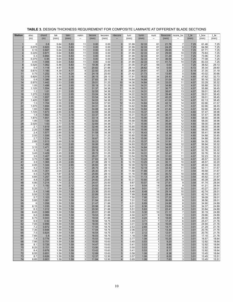
Table 3 shows the design thicknesses of composite laminates required at 74 sections along the blade. The optimal web locations are 12.8% and 56.0% of the chord length. The first column lists the blade section numbers and the second column lists the span location of those sections. The third column lists the chord lengths. The tsk, listed in the next column, is the design thickness of the double-bias skin material required at different blade stations. This thickness needs to be augmented such that it becomes an integer multiple of the commercially available double-bias composite ply. The tskn and nskin, listed in the next two columns, represent the augmented skin-laminate thickness and the number of plies required to obtain that thickness. The next three columns, with the headers tecore, tecoren, and ntecore, represent similar values for the core material (PVC foam) required at the blade trailing edge for resistance against buckling. The subsequent three columns, with the headers tuni, tunin, and nuni, represent corresponding values for the unidirectional material required in the box section. It is the unidirectional material that provides the majority of the bending stiffness and primarily meets the ultimate strength requirement. The tboxcore and ncore_bx represent the core-material thickness and the number of core plies required in the boxspar to meet the buckling-strength criterion. The t_le, t_box, and t_te, listed in the last three columns, respectively represent the blade section wall thickness at its leading edge, mid section (spanned by the boxspar), and trailing edge parts. The wall thickness at any point on the blade surface is the sum of the thickness of gelcoat, nexus, and all composite laminas at that point.
It should be noted that additional unidirectional and double-bias materials are used over the inboard blade span for blade root reinforcement. This reinforcement is required to
accommodate bolt inserts for blade attachment to the hub, to mitigate stress concentrations, and to provide smooth stress flow paths from the blade to the hub ([9] provides an empirical formula for the root design). The thickness of the reinforcement materials remains constant over a certain distance length from the blade root and then linearly tapers over the transition length, i.e., the length over which the blade section transitions from the circular shape to the regular airfoil shape. No core material is used over this blade-root region.
A close examination of the design results, listed in Table 3, suggests that the leading edge wall thickness might be too small for a tidal current turbine blade. While the shown thickness values are sufficient to meet the design criteria considered in the paper, these may not be adequate to withstand the crushing or impact loads from the water surrounding the blade. Specific design guidelines are being investigated to address this issue.
Finally, to make the blade near-neutrally buoyant, we consider water or epoxy slurry to fill the blade interior. A filler agent also helps reduce the fatigue-causing cyclic loads on the blade as discussed earlier. Though a filler does not contribute to the blade strength, it substantially increases the blade mass. The filler material also might mitigate buckling and crushing of the blade due to surrounding water; however, we did not consider these in the design.
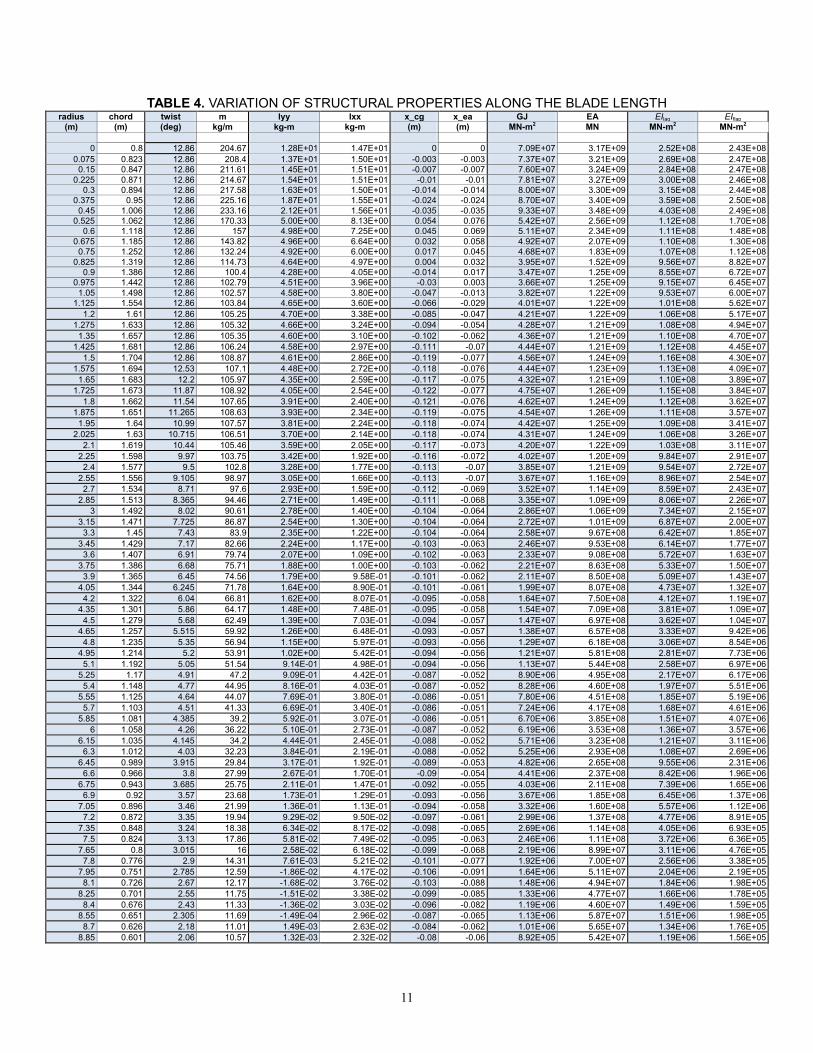
Structural Properties Next, using the composite layup that resulted from the
blade design, we computed the span-variant structural properties. Table 3 lists these properties. The m is the mass per unit length; Ixx is the section mass moment of inertia about the chord; Iyy is the section mass moment of inertia about any axis normal to the chord and originating from the pitch axis; EIflap is the flap stiffness; EIlag is the lag stiffness or edgewise stiffness; EA is the axial stiffness; GJ is the torsion stiffness; x_ea is the offset of the elastic-axis from the blade pitch axis; and x_cg is the offset of the section center of mass from the blade pitch axis. These offsets are positive if measured from the pitch axis toward the section leading edge. Note that the edgewise and torsion stiffness values dip around the 1.5-m span location. This is because both stiffness values are sensitive to the chord length (and are nearly proportional to the cube of the chord). Moving inboard from this location, the chord length reduces and so do the edgewise and torsion stiffness values. Further inboard, the chord is the diameter of a circular section and remains constant, but the root reinforcement contributes substantially to the stiffness values. The slight dips in the mass and mass-inertia distribution seen in the table can be interpreted similarly (mass is roughly proportional to chord and mass-inertia is nearly proportional to the cube of the chord).
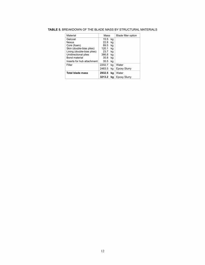
Table 5 provides a mass breakdown of the different materials used in the blade design. The contribution of mass of the bolt inserts and the filler material, though shown in the weight breakdown, is not included in section mass and inertia distributions shown in Table 4. The inserts behave more like a concentrated mass at the discreet root location rather than a distributed mass reflected in the tables.

9
After we account for the volume of the structural materials, the blade is left with a void of 24.9 m3 in its interior. We consider two options: filling the interior with water or with epoxy slurry to achieve near-neutral buoyancy. The blade weight increases by 2402.7 kilograms (kg) if water is considered, by 2483.5 kg if epoxy slurry is considered. The resulting blade total weight becomes 2932.5 kg for water filler and 3213.2 kg for epoxy slurry filler (see Table 5).
CONCLUSIONS AND FUTURE WORK We presented results of the preliminary structural design of
a horizontal-axis tidal turbine composite blade. The results show the optimal location of webs and the minimum thickness requirement of different composite laminates that would satisfy the ultimate-strength and buckling-resistance criteria. We considered only the extreme static loads that the blade would likely encounter during its lifetime. Dynamic loads, fatigue, and stiffness criteria will be considered in the future.
A close examination of the design results showed that the leading edge wall thickness, while adequate to meet the buckling and strength criteria, might be too small to withstand the crushing or impact loads from the water surrounding the blade. Specific design guidelines are being investigated to address this issue.
The design approach allows arbitrary twist, chord, and airfoil shape variation along the blade, but allows only a multi-cell boxspar. Though a boxspar design has been the choice by several HATT designers, we plan to extend our design code to accommodate a few more promising layouts. The materials we considered for the HATT design also appear adequate; however, we will critically assess other materials, which may be more suitable for HATT blades.
In the current preliminary design approach, we ignored warping and section in-plane distortion (Brazier effect). We have developed a code called PreComp [12], which accounts for these effects and also allows for arbitrary layup of composite laminates within the blade. However, its present capability is limited to computation of structural properties only. We plan to extend it to compute three-dimensional stresses and also allow automated design. Following a PreComp-assisted preliminary design, we will use a finite-element based analysis, such as NuMad [13], to refine the blade design and obtain a more accurate three-dimensional stress field.
REFERENCES [1] Fraenkel, P., 2002. “Power From Marine Currents”.
Proceedings of the Institution of Mechanical Engineers, Part A: Journal of Power and Energy, 216(1), pp. 1–14.
[2] Lawson, M. J., Li, Y., and Sale, D. C., 2011. “Development and Verification of a Computational Fluid Dynamics Model of a Horizontal Axis Tidal Current Turbine.” Proceedings of the 30th International Conference on Ocean, Offshore, and Arctic Engineering, Rotterdam, the Netherlands, June 19-24, 2011.
[3] Polagye, B., and Thomson, J., 2010. “Tidal Energy Reference Model Inflow Conditions,” University of Washington, unpublished technical report.
[4] Sale, D. C., and Li, Y., 2010. “Preliminary Results From a Design Methodology and Optimization Code for Horizontal Axis Wind and Hydrokinetic Turbines.” Proceedings of the 29th International Conference on Ocean, Offshore, and Arctic Engineering, Shaghai, China, June 6-11, 2010.
[5] NWTC Design Code Harp_Opt, available at: http://wind.nrel.gov/designcodes/simulators/HARP_Opt/, aceesed on December 15, 2010.
[6] NWTC Design Code WT_Perf, available at: http://wind.nrel.gov/designcodes/simulators/wtperf/, aceesed on December 15, 2010.
[7] Thomson J., Polagye, B., Richmond, M., and Durgesh, V. “Quantifying Turbulence for Tidal Power Applications”, MTS/IEEE Oceans 2010, Seattle, WA September 20–23, 2010.
[8] CD-Adapco, 2011, STAR CCM+ 5.06 User’s Guide. [9] Bir, G. S. and Migliore, P., 2001, “A Computerized Method
for Preliminary Structural Design of Composite Wind Turbine Blades.” Special November 2001 wind issue of the Journal of Solar Engineering. Also presented at the 2001 AIAA/ASME Wind Energy Symposium, Reno, NV.
[10] Hodges, D. H. and Dowell, E. H., 1974, “Nonlinear Equations of Motion for the Elastic Bending and Torsion of Twisted Nonuniform Rotor Blades,” NASA TN D-7818.
[11] Mandell, J. F. and Samborsky, D. D., 1997, “DOE/MSU Composite Material Fatigue Database: Test Methods, Materials, and Analysis,” SAND97-3002, Sandia National Laboratories, Albuquerque, NM.
[12] Bir, G. S., 2006, “User's Guide to PreComp (Pre-Processor for Computing Composite Blade Properties)”, NREL Report No. TP-500-38929.
[13] Laird, D. L., 2001, “NuMAD User’s Manual”, SAND2001-2375, Sandia National Laboratories, Albuquerque, NM.
10
TABLE 3. DESIGN THICKNESS REQUIREMENT FOR COMPOSITE LAMINATE AT DIFFERENT BLADE SECTIONS Station sloc chord tsk tskn nskin tecore tecoren ntecore tuni tunin nuni tboxcore ncore_bx t_le t_box t_te
(m) (m) (mm) (mm) -- (mm) (mm) -- (mm) (mm) -- (mm) -- (mm) (mm) (mm)
1 0 0.8 5.64 5.83 11 0.00 0.00 0 31.99 32.33 61 21.78 7 7.25 61.46 7.25 2 0.075 0.823 5.64 5.83 11 0.00 0.00 0 31.99 32.33 61 24.25 8 7.25 64.58 7.25 3 0.15 0.847 5.64 5.83 11 0.00 0.00 0 31.99 32.33 61 26.65 9 7.25 67.71 7.25 4 0.225 0.871 5.64 5.83 11 0.00 0.00 0 31.99 32.33 61 29.00 10 7.25 70.83 7.25 5 0.3 0.894 5.64 5.83 11 0.00 0.00 0 31.99 32.33 61 31.29 11 7.25 73.96 7.25 6 0.375 0.95 5.64 5.83 11 0.00 0.00 0 31.99 32.33 61 36.59 12 7.25 77.08 7.25 7 0.45 1.006 5.64 5.83 11 0.00 0.00 0 31.99 32.33 61 41.72 14 7.25 83.33 7.25 8 0.525 1.062 5.48 5.83 11 19.36 21.88 7 31.05 31.27 59 0.00 0 7.25 38.52 29.13 9 0.6 1.118 4.97 5.30 10 20.82 21.88 7 28.14 28.62 54 0.00 0 6.72 35.34 28.60
10 0.675 1.185 4.39 4.77 9 22.50 25.00 8 24.88 24.91 47 3.39 2 6.19 37.35 31.19 11 0.75 1.252 3.78 4.24 8 24.19 25.00 8 21.42 21.73 41 13.90 5 5.66 43.02 30.66 12 0.825 1.319 3.16 3.18 6 26.15 28.13 9 17.91 18.02 34 24.43 8 4.60 47.62 32.73 13 0.9 1.386 2.58 2.65 5 27.83 28.13 9 14.64 14.84 28 31.04 10 4.07 50.16 32.20 14 0.975 1.442 2.53 2.65 5 29.01 31.25 10 14.36 14.84 28 33.03 11 4.07 53.29 35.32 15 1.05 1.498 2.48 2.65 5 30.19 31.25 10 14.05 14.31 27 34.86 12 4.07 55.88 35.32 16 1.125 1.554 2.48 2.65 5 31.37 34.38 11 14.08 14.31 27 36.77 12 4.07 55.88 38.45 17 1.2 1.61 2.51 2.65 5 32.55 34.38 11 14.22 14.31 27 38.67 13 4.07 59.01 38.45 18 1.275 1.633 2.51 2.65 5 33.04 34.38 11 14.22 14.31 27 39.46 13 4.07 59.01 38.45 19 1.35 1.657 2.51 2.65 5 33.54 34.38 11 14.24 14.31 27 40.25 13 4.07 59.01 38.45 20 1.425 1.681 2.52 2.65 5 34.03 34.38 11 14.28 14.31 27 41.04 14 4.07 62.13 38.45 21 1.5 1.704 2.55 2.65 5 34.53 37.50 12 14.43 14.84 28 42.12 14 4.07 62.66 41.57 22 1.575 1.694 2.58 2.65 5 34.31 34.38 11 14.62 14.84 28 41.76 14 4.07 62.66 38.45 23 1.65 1.683 2.62 2.65 5 34.08 34.38 11 14.82 14.84 28 41.40 14 4.07 62.66 38.45 24 1.725 1.673 2.65 3.18 6 33.59 34.38 11 15.03 15.37 29 37.11 12 4.60 57.47 38.98 25 1.8 1.662 2.70 3.18 6 33.37 34.38 11 15.31 15.37 29 36.77 12 4.60 57.47 38.98 26 1.875 1.651 2.73 3.18 6 33.14 34.38 11 15.44 15.90 30 36.57 12 4.60 58.00 38.98 27 1.95 1.64 2.75 3.18 6 32.92 34.38 11 15.58 15.90 30 36.21 12 4.60 58.00 38.98 28 2.025 1.63 2.77 3.18 6 32.69 34.38 11 15.71 15.90 30 35.86 12 4.60 58.00 38.98 29 2.1 1.619 2.80 3.18 6 32.46 34.38 11 15.85 15.90 30 35.50 12 4.60 58.00 38.98 30 2.25 1.598 2.80 3.18 6 32.02 34.38 11 15.85 15.90 30 34.80 12 4.60 58.00 38.98 31 2.4 1.577 2.85 3.18 6 31.58 34.38 11 16.12 16.43 31 34.16 11 4.60 55.41 38.98 32 2.55 1.556 2.80 3.18 6 31.13 31.25 10 15.85 15.90 30 33.38 11 4.60 54.88 35.85 33 2.7 1.534 2.75 3.18 6 30.67 31.25 10 15.56 15.90 30 32.66 11 4.60 54.88 35.85 34 2.85 1.513 2.69 3.18 6 30.23 31.25 10 15.25 15.37 29 31.91 11 4.60 54.35 35.85 35 3 1.492 2.63 2.65 5 30.06 31.25 10 14.93 15.37 29 34.88 12 4.07 56.94 35.32 36 3.15 1.471 2.58 2.65 5 29.62 31.25 10 14.59 14.84 28 34.05 11 4.07 53.29 35.32 37 3.3 1.45 2.51 2.65 5 29.18 31.25 10 14.25 14.31 27 33.21 11 4.07 52.76 35.32 38 3.45 1.429 2.45 2.65 5 28.72 31.25 10 13.90 14.31 27 32.47 11 4.07 52.76 35.32 39 3.6 1.407 2.39 2.65 5 28.27 31.25 10 13.54 13.78 26 31.63 11 4.07 52.23 35.32 40 3.75 1.386 2.32 2.65 5 27.83 28.13 9 13.16 13.25 25 30.80 10 4.07 48.57 32.20 41 3.9 1.365 2.26 2.65 5 27.39 28.13 9 12.78 13.25 25 30.11 10 4.07 48.57 32.20 42 4.05 1.344 2.19 2.65 5 26.93 28.13 9 12.39 12.72 24 29.28 10 4.07 48.04 32.20 43 4.2 1.322 2.12 2.12 4 26.75 28.13 9 11.99 12.19 23 32.42 11 3.54 50.11 31.67 44 4.35 1.301 2.04 2.12 4 26.30 28.13 9 11.58 11.66 22 31.45 11 3.54 49.58 31.67 45 4.5 1.279 1.97 2.12 4 25.85 28.13 9 11.16 11.66 22 30.72 10 3.54 46.45 31.67 46 4.65 1.257 1.90 2.12 4 25.38 28.13 9 10.74 11.13 21 29.75 10 3.54 45.92 31.67 47 4.8 1.235 1.82 2.12 4 24.92 25.00 8 10.31 10.60 20 28.78 10 3.54 45.39 28.54 48 4.95 1.214 1.74 2.12 4 24.47 25.00 8 9.87 10.07 19 27.81 9 3.54 41.74 28.54 49 5.1 1.192 1.66 2.12 4 24.02 25.00 8 9.41 9.54 18 26.85 9 3.54 41.21 28.54 50 5.25 1.17 1.59 1.59 3 23.82 25.00 8 8.96 9.01 17 30.37 10 3.01 43.27 28.01 51 5.4 1.148 1.59 1.59 3 23.36 25.00 8 8.48 8.48 16 29.18 10 3.01 42.74 28.01 52 5.55 1.125 1.59 1.59 3 22.89 25.00 8 7.99 8.48 16 28.44 10 3.01 42.74 28.01 53 5.7 1.103 1.59 1.59 3 22.41 25.00 8 7.50 7.95 15 27.25 9 3.01 39.09 28.01 54 5.85 1.081 1.59 1.59 3 21.94 25.00 8 7.01 7.42 14 26.06 9 3.01 38.56 28.01 55 6 1.058 1.59 1.59 3 21.47 21.88 7 6.51 6.89 13 24.86 8 3.01 34.90 24.89 56 6.15 1.035 1.59 1.59 3 20.98 21.88 7 6.01 6.36 12 23.64 8 3.01 34.37 24.89 57 6.3 1.012 1.59 1.59 3 20.50 21.88 7 5.51 5.83 11 22.41 8 3.01 33.84 24.89 58 6.45 0.989 1.59 1.59 3 20.01 21.88 7 5.00 5.30 10 21.17 7 3.01 30.19 24.89 59 6.6 0.966 1.59 1.59 3 19.53 21.88 7 4.50 4.77 9 19.92 7 3.01 29.66 24.89 60 6.75 0.943 1.59 1.59 3 19.04 21.88 7 3.99 4.24 8 18.65 6 3.01 26.00 24.89 61 6.9 0.92 1.59 1.59 3 18.56 18.75 6 3.49 3.71 7 17.37 6 3.01 25.47 21.76 62 7.05 0.896 1.59 1.59 3 18.05 18.75 6 3.01 3.18 6 16.05 6 3.01 24.94 21.76 63 7.2 0.872 1.59 1.59 3 17.55 18.75 6 2.53 2.65 5 14.71 5 3.01 21.29 21.76 64 7.35 0.848 1.59 1.59 3 17.04 18.75 6 2.06 2.12 4 13.35 5 3.01 20.76 21.76 65 7.5 0.824 1.59 1.59 3 16.54 18.75 6 1.61 2.12 4 12.91 5 3.01 20.76 21.76 66 7.65 0.8 1.59 1.59 3 16.03 18.75 6 1.18 1.59 3 11.57 4 3.01 17.10 21.76 67 7.8 0.776 1.59 1.59 3 15.53 15.63 5 0.77 1.06 2 10.25 4 3.01 16.57 18.64 68 7.95 0.751 1.59 1.59 3 15.00 15.63 5 0.40 0.53 1 9.20 3 3.01 12.92 18.64 69 8.1 0.726 1.59 1.59 3 14.47 15.63 5 0.41 0.53 1 8.86 3 3.01 12.92 18.64 70 8.25 0.701 1.59 1.59 3 13.95 15.63 5 0.50 0.53 1 8.52 3 3.01 12.92 18.64 71 8.4 0.676 1.59 1.59 3 13.42 15.63 5 0.41 0.53 1 8.17 3 3.01 12.92 18.64 72 8.55 0.651 1.59 1.59 3 12.89 15.63 5 0.58 1.06 2 8.38 3 3.01 13.45 18.64 73 8.7 0.626 1.59 1.59 3 12.37 12.50 4 0.57 1.06 2 8.00 3 3.01 13.45 15.51 74 8.85 0.601 1.59 1.59 3 11.84 12.50 4 0.65 1.06 2 7.63 3 3.01 13.45 15.51
11
TABLE 4. VARIATION OF STRUCTURAL PROPERTIES ALONG THE BLADE LENGTH radius chord twist m Iyy Ixx x_cg x_ea GJ EA EIlag EIflap
(m) (m) (deg) kg/m kg-m kg-m (m) (m) MN-m2 MN MN-m2 MN-m2
0 0.8 12.86 204.67 1.28E+01 1.47E+01 0 0 7.09E+07 3.17E+09 2.52E+08 2.43E+08
0.075 0.823 12.86 208.4 1.37E+01 1.50E+01 -0.003 -0.003 7.37E+07 3.21E+09 2.69E+08 2.47E+08 0.15 0.847 12.86 211.61 1.45E+01 1.51E+01 -0.007 -0.007 7.60E+07 3.24E+09 2.84E+08 2.47E+08
0.225 0.871 12.86 214.67 1.54E+01 1.51E+01 -0.01 -0.01 7.81E+07 3.27E+09 3.00E+08 2.46E+08 0.3 0.894 12.86 217.58 1.63E+01 1.50E+01 -0.014 -0.014 8.00E+07 3.30E+09 3.15E+08 2.44E+08
0.375 0.95 12.86 225.16 1.87E+01 1.55E+01 -0.024 -0.024 8.70E+07 3.40E+09 3.59E+08 2.50E+08 0.45 1.006 12.86 233.16 2.12E+01 1.56E+01 -0.035 -0.035 9.33E+07 3.48E+09 4.03E+08 2.49E+08
0.525 1.062 12.86 170.33 5.00E+00 8.13E+00 0.054 0.076 5.42E+07 2.56E+09 1.12E+08 1.70E+08 0.6 1.118 12.86 157 4.98E+00 7.25E+00 0.045 0.069 5.11E+07 2.34E+09 1.11E+08 1.48E+08
0.675 1.185 12.86 143.82 4.96E+00 6.64E+00 0.032 0.058 4.92E+07 2.07E+09 1.10E+08 1.30E+08 0.75 1.252 12.86 132.24 4.92E+00 6.00E+00 0.017 0.045 4.68E+07 1.83E+09 1.07E+08 1.12E+08
0.825 1.319 12.86 114.73 4.64E+00 4.97E+00 0.004 0.032 3.95E+07 1.52E+09 9.56E+07 8.82E+07 0.9 1.386 12.86 100.4 4.28E+00 4.05E+00 -0.014 0.017 3.47E+07 1.25E+09 8.55E+07 6.72E+07
0.975 1.442 12.86 102.79 4.51E+00 3.96E+00 -0.03 0.003 3.66E+07 1.25E+09 9.15E+07 6.45E+07 1.05 1.498 12.86 102.57 4.58E+00 3.80E+00 -0.047 -0.013 3.82E+07 1.22E+09 9.53E+07 6.00E+07
1.125 1.554 12.86 103.84 4.65E+00 3.60E+00 -0.066 -0.029 4.01E+07 1.22E+09 1.01E+08 5.62E+07 1.2 1.61 12.86 105.25 4.70E+00 3.38E+00 -0.085 -0.047 4.21E+07 1.22E+09 1.06E+08 5.17E+07
1.275 1.633 12.86 105.32 4.66E+00 3.24E+00 -0.094 -0.054 4.28E+07 1.21E+09 1.08E+08 4.94E+07 1.35 1.657 12.86 105.35 4.60E+00 3.10E+00 -0.102 -0.062 4.36E+07 1.21E+09 1.10E+08 4.70E+07
1.425 1.681 12.86 106.24 4.58E+00 2.97E+00 -0.111 -0.07 4.44E+07 1.21E+09 1.12E+08 4.45E+07 1.5 1.704 12.86 108.87 4.61E+00 2.86E+00 -0.119 -0.077 4.56E+07 1.24E+09 1.16E+08 4.30E+07
1.575 1.694 12.53 107.1 4.48E+00 2.72E+00 -0.118 -0.076 4.44E+07 1.23E+09 1.13E+08 4.09E+07 1.65 1.683 12.2 105.97 4.35E+00 2.59E+00 -0.117 -0.075 4.32E+07 1.21E+09 1.10E+08 3.89E+07
1.725 1.673 11.87 108.92 4.05E+00 2.54E+00 -0.122 -0.077 4.75E+07 1.26E+09 1.15E+08 3.84E+07 1.8 1.662 11.54 107.65 3.91E+00 2.40E+00 -0.121 -0.076 4.62E+07 1.24E+09 1.12E+08 3.62E+07
1.875 1.651 11.265 108.63 3.93E+00 2.34E+00 -0.119 -0.075 4.54E+07 1.26E+09 1.11E+08 3.57E+07 1.95 1.64 10.99 107.57 3.81E+00 2.24E+00 -0.118 -0.074 4.42E+07 1.25E+09 1.09E+08 3.41E+07
2.025 1.63 10.715 106.51 3.70E+00 2.14E+00 -0.118 -0.074 4.31E+07 1.24E+09 1.06E+08 3.26E+07 2.1 1.619 10.44 105.46 3.59E+00 2.05E+00 -0.117 -0.073 4.20E+07 1.22E+09 1.03E+08 3.11E+07
2.25 1.598 9.97 103.75 3.42E+00 1.92E+00 -0.116 -0.072 4.02E+07 1.20E+09 9.84E+07 2.91E+07 2.4 1.577 9.5 102.8 3.28E+00 1.77E+00 -0.113 -0.07 3.85E+07 1.21E+09 9.54E+07 2.72E+07
2.55 1.556 9.105 98.97 3.05E+00 1.66E+00 -0.113 -0.07 3.67E+07 1.16E+09 8.96E+07 2.54E+07 2.7 1.534 8.71 97.6 2.93E+00 1.59E+00 -0.112 -0.069 3.52E+07 1.14E+09 8.59E+07 2.43E+07
2.85 1.513 8.365 94.46 2.71E+00 1.49E+00 -0.111 -0.068 3.35E+07 1.09E+09 8.06E+07 2.26E+07 3 1.492 8.02 90.61 2.78E+00 1.40E+00 -0.104 -0.064 2.86E+07 1.06E+09 7.34E+07 2.15E+07
3.15 1.471 7.725 86.87 2.54E+00 1.30E+00 -0.104 -0.064 2.72E+07 1.01E+09 6.87E+07 2.00E+07 3.3 1.45 7.43 83.9 2.35E+00 1.22E+00 -0.104 -0.064 2.58E+07 9.67E+08 6.42E+07 1.85E+07
3.45 1.429 7.17 82.66 2.24E+00 1.17E+00 -0.103 -0.063 2.46E+07 9.53E+08 6.14E+07 1.77E+07 3.6 1.407 6.91 79.74 2.07E+00 1.09E+00 -0.102 -0.063 2.33E+07 9.08E+08 5.72E+07 1.63E+07
3.75 1.386 6.68 75.71 1.88E+00 1.00E+00 -0.103 -0.062 2.21E+07 8.63E+08 5.33E+07 1.50E+07 3.9 1.365 6.45 74.56 1.79E+00 9.58E-01 -0.101 -0.062 2.11E+07 8.50E+08 5.09E+07 1.43E+07
4.05 1.344 6.245 71.78 1.64E+00 8.90E-01 -0.101 -0.061 1.99E+07 8.07E+08 4.73E+07 1.32E+07 4.2 1.322 6.04 66.81 1.62E+00 8.07E-01 -0.095 -0.058 1.64E+07 7.50E+08 4.12E+07 1.19E+07
4.35 1.301 5.86 64.17 1.48E+00 7.48E-01 -0.095 -0.058 1.54E+07 7.09E+08 3.81E+07 1.09E+07 4.5 1.279 5.68 62.49 1.39E+00 7.03E-01 -0.094 -0.057 1.47E+07 6.97E+08 3.62E+07 1.04E+07
4.65 1.257 5.515 59.92 1.26E+00 6.48E-01 -0.093 -0.057 1.38E+07 6.57E+08 3.33E+07 9.42E+06 4.8 1.235 5.35 56.94 1.15E+00 5.97E-01 -0.093 -0.056 1.29E+07 6.18E+08 3.06E+07 8.54E+06
4.95 1.214 5.2 53.91 1.02E+00 5.42E-01 -0.094 -0.056 1.21E+07 5.81E+08 2.81E+07 7.73E+06 5.1 1.192 5.05 51.54 9.14E-01 4.98E-01 -0.094 -0.056 1.13E+07 5.44E+08 2.58E+07 6.97E+06
5.25 1.17 4.91 47.2 9.09E-01 4.42E-01 -0.087 -0.052 8.90E+06 4.95E+08 2.17E+07 6.17E+06 5.4 1.148 4.77 44.95 8.16E-01 4.03E-01 -0.087 -0.052 8.28E+06 4.60E+08 1.97E+07 5.51E+06
5.55 1.125 4.64 44.07 7.69E-01 3.80E-01 -0.086 -0.051 7.80E+06 4.51E+08 1.85E+07 5.19E+06 5.7 1.103 4.51 41.33 6.69E-01 3.40E-01 -0.086 -0.051 7.24E+06 4.17E+08 1.68E+07 4.61E+06
5.85 1.081 4.385 39.2 5.92E-01 3.07E-01 -0.086 -0.051 6.70E+06 3.85E+08 1.51E+07 4.07E+06 6 1.058 4.26 36.22 5.10E-01 2.73E-01 -0.087 -0.052 6.19E+06 3.53E+08 1.36E+07 3.57E+06
6.15 1.035 4.145 34.2 4.44E-01 2.45E-01 -0.088 -0.052 5.71E+06 3.23E+08 1.21E+07 3.11E+06 6.3 1.012 4.03 32.23 3.84E-01 2.19E-01 -0.088 -0.052 5.25E+06 2.93E+08 1.08E+07 2.69E+06
6.45 0.989 3.915 29.84 3.17E-01 1.92E-01 -0.089 -0.053 4.82E+06 2.65E+08 9.55E+06 2.31E+06 6.6 0.966 3.8 27.99 2.67E-01 1.70E-01 -0.09 -0.054 4.41E+06 2.37E+08 8.42E+06 1.96E+06
6.75 0.943 3.685 25.75 2.11E-01 1.47E-01 -0.092 -0.055 4.03E+06 2.11E+08 7.39E+06 1.65E+06 6.9 0.92 3.57 23.68 1.73E-01 1.29E-01 -0.093 -0.056 3.67E+06 1.85E+08 6.45E+06 1.37E+06
7.05 0.896 3.46 21.99 1.36E-01 1.13E-01 -0.094 -0.058 3.32E+06 1.60E+08 5.57E+06 1.12E+06 7.2 0.872 3.35 19.94 9.29E-02 9.50E-02 -0.097 -0.061 2.99E+06 1.37E+08 4.77E+06 8.91E+05
7.35 0.848 3.24 18.38 6.34E-02 8.17E-02 -0.098 -0.065 2.69E+06 1.14E+08 4.05E+06 6.93E+05 7.5 0.824 3.13 17.86 5.81E-02 7.49E-02 -0.095 -0.063 2.46E+06 1.11E+08 3.72E+06 6.36E+05
7.65 0.8 3.015 16 2.58E-02 6.18E-02 -0.099 -0.068 2.19E+06 8.99E+07 3.11E+06 4.76E+05 7.8 0.776 2.9 14.31 7.61E-03 5.21E-02 -0.101 -0.077 1.92E+06 7.00E+07 2.56E+06 3.38E+05
7.95 0.751 2.785 12.59 -1.86E-02 4.17E-02 -0.106 -0.091 1.64E+06 5.11E+07 2.04E+06 2.19E+05 8.1 0.726 2.67 12.17 -1.68E-02 3.76E-02 -0.103 -0.088 1.48E+06 4.94E+07 1.84E+06 1.98E+05
8.25 0.701 2.55 11.75 -1.51E-02 3.38E-02 -0.099 -0.085 1.33E+06 4.77E+07 1.66E+06 1.78E+05 8.4 0.676 2.43 11.33 -1.36E-02 3.03E-02 -0.096 -0.082 1.19E+06 4.60E+07 1.49E+06 1.59E+05
8.55 0.651 2.305 11.69 -1.49E-04 2.96E-02 -0.087 -0.065 1.13E+06 5.87E+07 1.51E+06 1.98E+05 8.7 0.626 2.18 11.01 1.49E-03 2.63E-02 -0.084 -0.062 1.01E+06 5.65E+07 1.34E+06 1.76E+05
8.85 0.601 2.06 10.57 1.32E-03 2.32E-02 -0.08 -0.06 8.92E+05 5.42E+07 1.19E+06 1.56E+05
12
TABLE 5. BREAKDOWN OF THE BLADE MASS BY STRUCTURAL MATERIALS
Material Mass Blade filler option Gelcoat 15.5 kg Nexus 22.8 kg Core (foam) 89.5 kg Skin (double-bias plies) 120.1 kg Lining (double-bias plies) 23.7 kg Unidirectional plies 386.8 kg Bond material 35.8 kg Inserts for hub attachment 35.5 kg Filler 2202.7 kg Water 2483.5 kg Epoxy Slurry Total blade mass 2932.5 kg Water 3213.2 kg Epoxy Slurry