Structural Design 00 Scot u of t
178
-
Upload
jeremy-white -
Category
Documents
-
view
220 -
download
0
Transcript of Structural Design 00 Scot u of t
8/8/2019 Structural Design 00 Scot u of t
http://slidepdf.com/reader/full/structural-design-00-scot-u-of-t 1/177
8/8/2019 Structural Design 00 Scot u of t
http://slidepdf.com/reader/full/structural-design-00-scot-u-of-t 2/177

8/8/2019 Structural Design 00 Scot u of t
http://slidepdf.com/reader/full/structural-design-00-scot-u-of-t 3/177

8/8/2019 Structural Design 00 Scot u of t
http://slidepdf.com/reader/full/structural-design-00-scot-u-of-t 4/177

8/8/2019 Structural Design 00 Scot u of t
http://slidepdf.com/reader/full/structural-design-00-scot-u-of-t 5/177

8/8/2019 Structural Design 00 Scot u of t
http://slidepdf.com/reader/full/structural-design-00-scot-u-of-t 6/177
STRUCTURAL DESIGNERS'
HANDBOOK
GIVING DIAGRAMSAND TABLES FOR THE DESIGN OF
BEAMS, GIRDERS AND COLUMNS WITH CALCU-
LATIONS BASED ON THE NEW YORKCITY BUILDING CODE
BY
WILLIAM FRY SCOTT
Structural Engineer, Member American Society for Testing Materials
NEW YORK
THE ENGINEERING NEWS PUBLISHING CO.
1904

8/8/2019 Structural Design 00 Scot u of t
http://slidepdf.com/reader/full/structural-design-00-scot-u-of-t 7/177
Copyright, 1904
BY
WILLIAM FRY SCOTT
8/8/2019 Structural Design 00 Scot u of t
http://slidepdf.com/reader/full/structural-design-00-scot-u-of-t 8/177
PREFACE.
This handbook, essentially a diagrammatic treatise on the sub-
ject of Structural Design, contains also a full tabulation of the
properties of market shapes of materials.
It is presented to the architectural and engineering professions
with the thought that it may be the means of shortening and pos-
sibly eliminating much of the computation and drudgery which are
necessary accompaniments of structural designing.
It is hoped that it may prove useful to the expert designer,
since the diagrams presented are time-saving devices;useful and
suggestive to the non-expert and the student, since the diagrams
illustrate graphically the relations of the various factors of propor-
tion, span loading, etc., for the variable conditions of ordinary
practice.
Throughout the work the New York Building Code has been
followed, because it is everywhere recognized as conservative and
safe.
W. F. S.
New York, July, 1904.

8/8/2019 Structural Design 00 Scot u of t
http://slidepdf.com/reader/full/structural-design-00-scot-u-of-t 9/177

8/8/2019 Structural Design 00 Scot u of t
http://slidepdf.com/reader/full/structural-design-00-scot-u-of-t 10/177
CONTENTS.
PART I. SYNOPSIS OF MECHANICS OF THEBEAM AND COLUMN.
CHAPTER I. BEAMS.Page
Span 1
Cross Section 1
Section Moment 1
Unit Stress 2
Manner of Support 2
Deflection2End Reactions 3
Buckling of Compression Flange 4
Loads on Beams 4
Conventional Methods of Treating Loads on Floor Girders. ... 5
Conventional Methods of Considering Loads on Grillage Beams 7
CHAPTER II. COLUMNS.
Concentric Loads 8
Eccentric Loads 8
PART. II. BEAMWORK.CHAPTER III. FLOOR FRAMING.
Utility of Diagrams 11
Explanation of Diagrams 1 to 15 12
Explanation of Tables 1 to 15 13
Explanation of Diagrams 16 to 21 14
Explanation of Diagram 22 15
Explanation of Tables of Properties of Shapes 16
Tables 1 to 15, Giving Percentage of Allowable load, Spac-
ing and End Reaction for I-Beams' from 3-in. x 5.5 Ib. to
24-in. x 80-lb .18-46
Diagrams 1 to 15. Giving Allowable Uniform Load, Spac-
ing, Span, etc., for I-Beams from 3-in. 1 x 5.5-lb. to 24-
in. x 80-lb 18-46
Diagrams 16 to 21. Giving Allowable Uniform Load, Spac-
ing, Span, etc., for Angles and Tees as Beams or Gir-
ders 48-51
Diagram 22. For Reducing the Value of a Concentrated
Load to an Equivalent Value of Uniform Load per
Unit Floor Area 52
CHAPTER IV. SPANDREL BEAMS.
Explanation of Diagram 23 63
Explanation of Diagrams 24, 25, 26 WDiagram 23. For Giving an Equivalent Value of Load Con-
centrated in the Middle of a Span for any Value of a
Concentrated Load at any Other Point 56

8/8/2019 Structural Design 00 Scot u of t
http://slidepdf.com/reader/full/structural-design-00-scot-u-of-t 11/177
vi CONTENTS.
Page
Diagram 24. For giving the Allowable Load on Standard
and Special 3-in. to 15-in. I-Beams 57
Diagram 25. For giving the Allowable Load on Standard
and Special 10-in. to 24-in. I-Beams 58
Diagram26. For
givingthe Allowable Load on 3-in. to 15-
in. Standard and Special Channels 59
CHAPTER V. GRILLAGE BEAMS.
Footings 60
Design 60
Bending 60
Buckling of the Web 62
Explanation of Diagram 27 62
Diagram 27. For giving Size, Weight and Spacing of I-
Beams necessary for each of the several tiers in a gril-
lage footing 63
Example of Use of Diagram 63
CHAPTER VI. END REACTIONS.
Explanation of Diagram 28 (35
Design and 'Sizes of Standard Connection Angles 66
Explanation of Table 16 67
Design of Bearing Plates 68
Explanation of Diagram 29 68
Table 16. For giving Maximum Allowable End Reaction on
Standard and Special Connection Angles, also RelativeValues of the Several Sizes of Rivets 69
Diagnam 28. For giving Values for Rivet Requirements in
Connection Angles, also Areas' for Bearing Plates 70
Diagram 29. For giving Thickness' of Beam Plates of Cast
Iron, Wrought Iron or Steel 71
PART III. COLUMNS AND TRUSS MEMBERS.CHAPTER VII. STEEL COLUMNS.
Ratio of Slenderness 73
Explanation of Diagrams 30 to 34 73-78
Diagram 30. For giving the Radius of Gyration of the most
Common Forms of Column Sections of Wood, Cast Iron
or Steel 79
Diagram 31. For giving the Radius of Gyration of the Most
Common Forms of Built-up Column Sections 80
Diagram 32. For giving the Ratio of Slenderness of a Col-
umn ; si
Diagram 33. For giving the Safe Loads on Steel Columns as
Called for by the New York Building Code for Ratios of
Slenderness up to 120 and as Recommendedby
theAu-thor for Ratios Between 120 and 200 82
Diagram 34. Eccentric Loading on Columns. For giving
Percentage of Material Necessary to Add to the Cross-
Section of a Column for any Eccentricity of the Centerof Gravity of Its Load, with Reference to the AxialPlanes Through Its Neutral Axis' . $3

8/8/2019 Structural Design 00 Scot u of t
http://slidepdf.com/reader/full/structural-design-00-scot-u-of-t 12/177
CONTENTS. vii
PageCHAPTER VIII. TABLES.
Explanation of Tables, giving Properties of Single and Built-
up Steel Shapes of I-Beams, Channels, Angles, Tees,
Zees and Flats for Use in Columns, Beams and Trusses 84
Table 17. Steel I-Beams. For Beams, Girders, Columns or
Truss Members 90
Table 18. Steel Channels for Beams, Girders, Columns or
Truss Members 94
Table 19. Plate and Channel Columns 95
Table 20. Steel Angles (even legs) far Beams, Girders, Col-
umns or Truss Members 102
Table 21. Steel Angles (uneven legs) for Beams, Girders,
Columns or Truss Members 104
Table 22. Plate and Anffle Columns, With and Without
Cover Plates .*. . . 107
Table 23. Steel Tees for Beams, Girders, Columns or Truss1
Members 108
Table 24. Steel Zee-bars for Beams, Girders, Columns or
Truss Members '. 110
Table 25. Weights of Flat Rolled Steel Ill
CHAPTER IX. CAST-IRON COLUMNS.
Explanation of Diagrams 35, 36 113
Diagram 35. For giving the Safe Loads on Cast-iron Col-
umns as Specified by the New York Building Code. . . . 114
Diagram 36. For giving the Safe Loads on Cast-iron Col-umns as Recommended by the Author 115
Tables 26 to 30. Weight and Thickness of Metal of Cast-iron
Column Sections 116-118
Table 31. Weight and Thickness of Metal of Cast-iron Gas
Pipe 118
PART IV. MISCELLANEOUS.
CHAPTER X. LOADS.
Explanation of Diagrams 37 and 38 119
Diagram 37. For Giving the Weight of Steel Required in
Floors where the Loads are a Minimum. 120
Diagram 38. For Giving the Weight of Steel Required in
Floors where the Loads are a Maximum 121
Diagram 39. For Giving the Weight of Joists per Square Foot
of Floor 122
Floor Arches 123
Flooring Material 123
Partitions 124
Brick Walls 124
Live Loads on Floors 1 -~>
On Footings 12r*
Wind Pressure on Buildings 1-!.~
CHAPTER XI. UNIT STRESSES.
Safe Load on Masonry Work 126
Strength of Columns 126

8/8/2019 Structural Design 00 Scot u of t
http://slidepdf.com/reader/full/structural-design-00-scot-u-of-t 13/177
viii CONTENTS.
Page
Working Stresses' 127
Compression12?
Tension 128
Shear 128
Safe Extreme Fiber Stress 128
Bearing Capacity of Soil 128
CHAPTER XII. BRICK WALLS.
Explanation of Diagram 40 129'
Diagram 40. For Giving Thickness and Weight of Walls for
Skeleton Structures, Warehouses or Dwelling Houses Ac-
cording to the New York Building Code 132
CHAPTER XIII. GERMAN, BELGIAN AND ENGLISH
I-BEAMS.
Explanation of Tables 32, 33 and 34 133
Table 32. Properties of German I-Beams 134
Table 33. Properties of Belgian I-Beams 134
Table 34. Properties of English I-Beams 134
CHAPTER XIV. FLEXURAL EFFICIENCY OF I-BEAMS
AND CHANNELS.
Explanation of Diagram 41 136
Diagram 41. For Givingthe Relative Flexural
Efficiencyof
I-Beams and Channels per Pound of Steel 137
CHAPTER XV. BASES AND LINTELS OF CAST IRON.
Methods of Design 138
Explanation of Diagram 42 139
Diagram 42. For Giving the Minimum Thickness for Bottom
Plate of Oast-iron Shoes 140
CHAPTER XVI. WOODEN BEAMS AND POSTS.
Explanation of Diagrams 43 to 51 142, 143
Diagrams 43 and 44. For Giving the Safe Load on White
Pine, Spruce or Chestnut Joists for Each Inch in
Breadth 144, 145
Diagrams 45 and 46. For Giving the Safe Load on Long Leaf
Yellow Pine or Locust Joists for Each Inch in Breadth
146, 147
Diagrams 47 and 48. For Giving the Safe Load on White
Pine, Spruce or Chestnut Girders for Each Inch in
Breadth 148, 149
Diagrams 49 and 50. For Giving the Safe Load on Long Leaf
Yellow Pine or Locust Girders for Each Inch in Breadth.
150, 151
Diagram 51. For Giving Safe Load on White Pine, WhiteOak and Yellow Pine Posts, Ratio of Length to Least
Radius of Gyration, Area of Section in Square Inches and
Ratio of Length to Least Diameter (both in inches). .. . 152

8/8/2019 Structural Design 00 Scot u of t
http://slidepdf.com/reader/full/structural-design-00-scot-u-of-t 14/177

8/8/2019 Structural Design 00 Scot u of t
http://slidepdf.com/reader/full/structural-design-00-scot-u-of-t 15/177
2 STRUCTURAL DESIGNERS' HANDBOOK.
By computing the maximum bending moment due to the ex-
ternal forces, and referring to the values of section-moments, given
in the aforementioned tables, the proper structural shape to be
used can readily be found. (It should be noted that the section-moments are given in foot-pounds for angles and tees but in foot-
tons for all other shapes.)
The maximum UNIT STRESS permissible in structural steel
beams is throughout this book taken at 16,000 Ibs. per sq. in.
This is in accordance with the provisions of the "Code" (N. Y. C),
with the tables contained in the pocket books of the steel manu-
facturers, and with nearly all specifications for beamwork in build-
ings.
The MANNER OF SUPPORT of the beam affects its strength
quite materially. By far the most common case is where the
ends are "simply supported." The diagrams, with the single excep-
tion of that for grillage beams,* are based exclusively upon this
case, and for convenience in calculating the strength of beams under
other conditions of support, the following formulas are given :
WL= Ms, for a cantilever beam with load concentrated at the end. (i)=" 2 Ms, for a cantilever beam with load uniformly distributed. (2)
" =3 4 MB, for a simple beam supported at the ends, and load con-
centrated in the middle. (3)' =* 8 Ms, for a simple beam supported at the ends, and load uni-
formly distributed. (4)1
=5.2 Ms, for a beam with one end fixed and the other end sup-
ported, and load concentrated near the middle. (5)' = 8 Ms, for a beam with both ends fixed, and load concentrated
in the middle. (6)'
= 12 Ms, for a beam with both ends fixed, and load uniformly dis-
tributed. (7)
where
W. = Total load on beam, in tons or pounds.
L. = Span of beam, in feet.
Ms. = Section-moment, in foot-tons or foot-pounds.
The question of the DEFLECTION of beams is one of special
importance in many cases, as for instance, where plastered ceil-
ingsare involved.
One four-hundredthof the
span should gen-erally be the limit for such cases. The diagrams for spandrel and
floor beams are calculated for a limiting deflection of this amount.
For general practice there should be no objection to this limit,
These are virtually cases of cantilever beams.

8/8/2019 Structural Design 00 Scot u of t
http://slidepdf.com/reader/full/structural-design-00-scot-u-of-t 16/177
BEAMS.3
even where plastered ceilings are not involved. For bridge work
and some other cases, the deflection of beams is not usually con-
sidered, in which case the diagrams may be used by placing a
straight edge on the left hand portion of the curve and determiningthe intersection of this portion produced for the span and spacing
required.
For convenience in calculating the strength of beams for a
limiting deflection of one four-hundredth of the span, under the
several more common conditions of support, the following
formulas are given :
W L1 =0.566 h MB, for a cantilever beam with load concentrated at
the end. (8)=
1.51 h Ms, for a cantilever beam with load uniformly dis-
tributed. (9)
=9.05 h Ms, for a simple beam supported at the ends, and
load concentrated in the middle. (10)
=14-5 h Ms, for a simple beam supported at the ends, and load
uniformly distributed. (n)=
10.35 .h Ms, for a beam with one end fixed, and the other end
supported, and load concentrated near the
middle. (12)
" = 35-2 h Ms, for a beam with both ends fixed, and load con-
centrated in the middle. (13)"
=72.5 h Ms, for a beam with both ends fixed, and load uni-
formly distributed. (14)
where
W = Total load on beam, in tons.
L = Span of beam, in feet.
h = Depth of beam, in inches (for symmetrical sections only)*
Ms = Section-moment, in foot-tons.
The upward reaction of the support against the beam, is an
important matter as affecting its strength, and it should be kept in
mind in every case of their design.
THE END REACTIONS due to uniformly loading standard
beams up to their full allowable flexure strength for various spans
are given on Diagram No. 28 in Chapter VI. These are the ex-
ternal loads which are resisted by stresses in the webs of the
beams. These stresses are of
importanceprincipally in very short
beams loaded to their full bending capacity. The following is a
discussion on these stresses, all mathematical reasoning being
omitted for the sake of brevity :
The end reaction, divided by the area of the web (usually considering
the height of the beam times the web thickness), equals the unit intensity

8/8/2019 Structural Design 00 Scot u of t
http://slidepdf.com/reader/full/structural-design-00-scot-u-of-t 17/177
4 STRUCTURAL DESIGNER? HANDBOOK.
of the vertical shearing stress in the web. While not absolutely correct,
the above statement is practically true. This unit intensity of vertical shear
is equal to the unit intensity of shearing stress acting at angles of 45 with
the neutral axis of thebeam,
and theseagain
areequivalent
to direct com-
pressive and tensile stresses in the web, acting at right angles to each other.
The compressive stress will evidently tend to buckle the web, while the
tensile stress will tend to hold it in its true plane. Neglecting the value of
the tensile stress (which is really indeterminate), or in other words, placing
the "factor of ignorance" on the safe side of the problem, then the unit
intensity of the compressive stress should for safety not exceed the allowable
unit compressive stress in any strip of the web between the fillets, at 45
with the neutral axis of the beam.
When the ratio of the length of any such strip to the least radius of
gyration of the web exceeds no (which is the point at which the shearing
strength practically becomes equal to the compressive strength) then the
allowable end reaction should be determined by the permissible compressive
stress in the web; when the ratio is less than no the allowable reaction
should be determined by the permissible shearing stress.
Tables opposite each of the Diagrams Nos. I to 15 and also
the tables for I-beams and channels in Chapter VIII give these
values, according to the "Code" (N. Y. C.) requirements for shear-
ing and compressivestresses.
(See Chap.XI on unit
stresses.)
BUCKLING OF COMPRESSION FLANGE. Floor beams usu-
ally have their compression flanges supported laterally by the floor
arches, and the girders have their flanges supported by the beams
which frame into them. When the lateral supports are so far apart
that the upper flange of the beam, considered as a column, would
begin to deflect under a load equivalent to the compressive stress
in that flange, ,then the load on the beam in flexure should be re-
duced. In the Diagrams Nos. I to 15, this reduction of load is
given for different lengths of flange between lateral supports. As
is explained in Chapter III, a scale at the bottom of these dia-
grams gives for any unsupported length of flange in feet the maxi-
mum percentage of full load that can be safely carried without
danger of buckling of the upper flange.
LOADS ON BEAMS. The bending stress due to a concentrated
load depends upon the amount of the load and its position on thebeam with reference to the span. The most unfavorable position
is at the center, the bending stress in this case being twice that due
to the same load uniformly distributed. As the load moves towards
either end, the bending stress produced by it decreases. In each
case, the greatest stress in the beam is directly below the load.
8/8/2019 Structural Design 00 Scot u of t
http://slidepdf.com/reader/full/structural-design-00-scot-u-of-t 18/177
BEAMS. 5
Thus, when the load is not at the center of the beam, the stress at
the center due to the load is less than the stress directly under the
load.
This is of importance in the case of combined loads. The
bending stress due to a combination of concentrated loads (with
or without a uniform load) is greatest at a point of the beam
near the center of gravity of the loads. Moreover, the maximum
stress is somewhat less than the sum of the maximum stresses due
to each of the uniform or concentrated loads acting alone.
CONVENTIONAL METHODS OF CONSIDERING LOADS
ON BEAMS.
The' scope of the present book will not admit of discussing
more than the two special cases, under this heading, that are in-
volved in the methods of constructing the diagrams on beamwork.
The first is a consideration of the conventional treatment of uni-
form loading on floor girders in terms of unit floor area. The
second is a discussion of the two principal conventional methods
of considering the loads on grillage beams.
CONVENTIONAL METHOD OF TREATING LOADS ON FLOOR
GIRDERS. The diagrams in Chapter III on beams refer directly to
uniform loading per square foot of floor. Since the main girders in
a floor support the floor beams, and thus carry what are essentially
concentrated loads, it may at first sight be thought that the same
diagrams could not be directly applicable to girders. This is not the
case, however, as will be evident by considering a girder with a single
concentrated load in the center. The strength of this girder is or-
dinarily found in terms of the load and the span of the girdjer. The
external bending moment, for instance, is equal to one-fourth of
the span in feet multiplied by the amount of the concentrated load
in tons or pounds, according to the units adopted by the designer.
Suppose, now, that this concentrated load is due to two beams
framing into the girder, one on each side, and in order to simplify
the problem, suppose the spans of these two beams to be equal, of
the value B.* Then if L equals the span of the girder, W the load-
*If the beams framing into the girder have spans that are unequal,
then (B) is equal to one-half the sum of the spans.

8/8/2019 Structural Design 00 Scot u of t
http://slidepdf.com/reader/full/structural-design-00-scot-u-of-t 19/177
6 STRUCTURAL DESIGNERS' HANDBOOK.
ing on the beams in pounds per square foot of floor, Mb the exter-
nal bending moment on the girder, and C the concentrated load on
the girder due to the two beams, we have,
L C WBLMb =
,and C = ,
4 2
or
WBL2
Mb =8
But if the girder were considered loaded with a uniform load
W per square foot, distributed over the area represented by breadth
B and length L, the moment on the girder would be
WBL2
Mb =,
8
which is the same as found by the other method.
It will be found on analysis, that the result obtained in this
particular case can be safely applied to the case of a girder with
any number of beams framing into it. Thus, so long as girders
are designed in terms of the actual area enclosed within the
parallelogram having a breadth B and length L, and the uniform
load W per unit area, the diagrams will be found to give safe re-
sults. In all cases where odd numbers of beams (even number of
spaces between ends) frame into girders, the values given in the
diagrams are just as true for girders as for simple beams, pro-
vided the sum x>f the spans of the floor arches does not exceed
length L, while in the case of even numbers of beams framing into
girders, the diagrams give values that are a little safer than in the
other cases. There are only three cases where the difference is
perceptible where two, four or six beams frame into the girder
(respectively three, five or seven spaces between the ends of the
girder). They differ from the diagram values as follows :
Two beams, Mb = V. W B L2 = o.m WBL1
Four beams, Mb = %o W B L1
= 0.120 WBL1
Six beams, Mb = */ W B L1 = 0.122 W B L1
Uniform load, Mb = */ W B L1 =0.125 WBL1
For more than six beams, the moment practically equals that
for uniform load. For the three cases given above, the permissible
loading on the girder is respectively 12\%, 4% and 2% greater
8/8/2019 Structural Design 00 Scot u of t
http://slidepdf.com/reader/full/structural-design-00-scot-u-of-t 20/177
BEAMS. 7
than that given by the diagrams. Therefore in these three cases
the results obtained from the diagrams can be corrected as follows :
Increase the load per square foot by 12$%, 4% and 2% re-
spectively, for the three cases;or increase the spacing of the girders
by the same percentages, in which case the load is not changed ;or
increase the span of the girders 6%, 2% and i% respectively.
CONVENTIONAL METHODS OF CONSIDERING LOADS ONGRILLAGE BEAMS. Correctly speaking there is only one condi-
tion that actually represents the effect of the load on a grillage foot-
ing, but usage in design is sometimes contradictory when the prem-ises are not well understood. This is well illustrated in two meth-
ods of designing grillage beams in footings. For instance, one
method considers the active portion of the load to be on the pro-
jecting length of the beam only, and the bending moment calcu-
lated at the edge of the base above, or the edge of the tier of beams,
if such exists, is assumed to be the maximum bending moment on
the footing. The second method considers the bending moment
at the center, due to all the external forces acting on the footing.
The formulas for the two methods are:
First Method:
Wa2
Mb= (15)2
where Mb = Bending moment under edge of tier above,
W = Load per unit length of beam,
a = Length of projecting portion of beam.
Second Method:
a f b 1 W a2
f b 1
Mb =W- a +- = i + (16)2 I 2 } 2 I 2a J
where Mb = Maximum bending moment at center,
b = Width of base or tier above,
a = Projecting portion of beam.
Comparing these two formulas, the maximum bending mo-
b
ment on the footing is i + times the bending moment occur-
2a
ring under the edge of the tier above.
It will thus be seen that the bending moment at the center is
b
greater by the percentage than the moment at the edge of the
2a
base. The use of formula (15) would therefore appear to lead to

8/8/2019 Structural Design 00 Scot u of t
http://slidepdf.com/reader/full/structural-design-00-scot-u-of-t 21/177
8 STRUCTURAL DESIGNERS' HANDBOOK.
an unsafe design. It has been found by experience, however,
that the concrete in the footing goes to form a composite beam of
considerable excess strength over that of the steel beams alone, and
designs have been made by experienced engineers in which this
excess has apparently been assumed to be from 25% to 75% (on
the basis of 16,000 Ibs. per sq. in. maximum fiber stress).
This question will be further discussed in the Chapter on Grill-
age Beams.
CHAPTER II. COLUMNS.
A column is designed to resist forces which usually act in the
direction of its axis the center of gravity of these forces maycoincide with or may be a short distance from and parallel to this
axis. In the former case they are called "Concentric" loads, in
the latter case "Eccenti ic" loads.
CONCENTRIC LOADS. A column in direct compression, if
securedagainst
lateral deflection
might safelybe
designedto de-
velop the full allowable unit compressive stress for the material.
However, if any slight deflection of the axis from a straight line
takes place, the load acts to produce flexure stresses in addition to
the direct compressive stress. For this reason columns cannot
safely be designed for the full working unit stress that is allowed for
the material in simple compression. This tendency of a column to
deflect depends upon the ratio between its length and least radius of
gyration.This ratio
maybe called the ratio of slenderness of the
column. Column formulas based on this ratio exist in great variety
the "load" diagrams for columns (in Part III) are based on the
formulas prescribed by the "Code" (N. Y. C).
ECCENTRIC LOADS. When a column is eccentrically loaded
the stresses produced in any cross section are a uniform com-
pressive stress of the same value as would be produced by a con-
centric load of the same amount, and the stresses due to a bending
moment caused by the eccentricity of the load. The sum of these
stresses is a maximum on the compressive side of a cross section at
or near the bottom of the bracket which transmits the larger share
of the eccentric load into the column, and it is a minimum at the
foot of the column. However, as the cross section of a column is
usually- made uniform throughout its length, it is not necessary to

8/8/2019 Structural Design 00 Scot u of t
http://slidepdf.com/reader/full/structural-design-00-scot-u-of-t 22/177
COLUMNS. 9
consider any but the maximum stresses. This cross section is
therefore designed so that the sum of the compressive stresses due
to the bending moment and the compressive stress due to a con-
centric load of the same amount shall not exceed the safe unit com-
pressive stress allowable on a column with the given ratio of slen-
derness.
The area of the cross section of a column required to resist
the compressive stress due to a concentric load is found by divid-
ing the load by the allowable unit stress obtained from the afore-
mentioned column formulas, while the area required to resist the
compressive stresses due to the eccentric load is a much more com-
plex problem. It is usually based on the following considerations :
Fig. i shows a column eccentrically loaded. The load Pe is applied
at a distance a from the neutral axis of the column and the extreme
fiber of the column is at a distance3;from its neutral axis. Then
the bending moment produced in the column by the eccentricity of
loading is expressed by the formula.
Mb = zP (17)
where P = Pe + PC and z equals distance from the neutral
axis to the center of gravity of the loads; and the requiredsection-moment is
SI S A r*
Ms= =, (18)
y y
in which S represents the allowable unit stress in the
material, I the moment of inertia of the cross section (I
being equal to the area A of the section, times the square
of r, the radius of gyration).
Now putting the section-moment equal to the external
bending moment,
SAr'z p = ,
from which
Fig. 1. A=zy
(19)
This expression shows that the area required for bending
alone is given by considering the eccentric load as a pure concen-
tric load, and multiplying the area thus considered, by a factor
S
which depends upon the distance of the center of gravity of the
8/8/2019 Structural Design 00 Scot u of t
http://slidepdf.com/reader/full/structural-design-00-scot-u-of-t 23/177
10 STRUCTURAL DESIGNERS' HANDBOOK.
loads from the neutral axis, the distance of the extreme fiber from
the neutral axis, and the radius of gyration of the section. The
term 2 y is conveniently called the coefficient of eccentricity.
z yThe factor -, it should be noted, simply gives the percentage of area
of a column section as calculated for a concentric load which it is necessary
to add to take care of the added stress due to the eccentricity of the load.
If the load is eccentric on both axes, then two of these percentages must
be determined. Thus the area of a column which is eccentrically loaded in
both principal directions is expressed by the formula:
Where P = Pe + PC = total load on the column.
S = allowable unit stress in the material and determined by the
minimum radius of gyration.
Z', y' and r' being taken about the minor axis and z", y" and r"
about the major axis.
This subject will be continued in Chapter VII on steel col-
umns.

8/8/2019 Structural Design 00 Scot u of t
http://slidepdf.com/reader/full/structural-design-00-scot-u-of-t 24/177
Part II. Beamwork.
CHAPTER III. FLOOR FRAMING.
UTILITY OF DIAGRAMS. The strength of beams and girders*
is
givenin
almostall
books on the subject in terms of the totaluniform load which they will safely carry. If the beams are used
in floors, where the loads are mostly uniform and known in terms
of the unit floor area, it is necessary to perform a more or less
lengthy calculation to determine the spacing of the floor beams un-
der consideration, and these calculations have to be repeated for
every problem. The diagrams in this chapter eliminate the need
for calculations of this sort, and enable the proper spacing of beams
and girdersof
an assumedsize to
be readoff at
oncefor
any givenspan, and any given load per square foot of floor.
An equally important application of the diagrams may be
made at an earlier stage of the work. It is quite generally recog-
nized that the time to consider economy of material in the frame-
work of a building is at that stage of the development of the plan
when the architect and the owner are "getting together" on the
matter of what can be done for the money to be invested. Any
excessin the
spanof
beamsand
girdersover the minimum re-
quired by the particular conditions governing in each case, adds to
the cost of the steelwork. The diagrams in this chapter will be
found useful in deciding upon an economical arrangement of col-
umns in such cases. It will be evident that when once the spacing
of columns is fixed, there can be comparatively little room for con-
sideration of economy in beam arrangement.
Thus these diagrams will be found valuable in preliminary
workfor two
specialreasons :
(i)
Severalpossible arrangements
of
beams and girders can be studied in a few minutes by their use. (2)
The weight of steel for every case being given, the most economical
"The word "beam" is used throughout this book to signify beams used
as joists or rafters, and the word "girder" to signify beams used as sup-
ports for joists or rafters.
(11)

8/8/2019 Structural Design 00 Scot u of t
http://slidepdf.com/reader/full/structural-design-00-scot-u-of-t 25/177
12 STRUCTURAL DESIGNERS* HANDBOOK.
arrangement of beams and girders will be evident without any
figuring.
The first fifteen diagrams cover the standard weight of I-beam
in each of the various sizes, and their use is extended to channels
and special I-beams by means of the supplementary tables which
are placed opposite each diagram. The next six diagrams cover
angles and tees used as beams. A special diagram is added to this
group, which extends its use to the consideration of minor concen-
trated loads by giving an equivalent uniform load.
DIAGRAMS FOR I-BEAMS AND CHANNELS (NOS. 1 TO 15):
A separate diagram has been drawn for each standard I-beam;
thus Diagram No. 6 refers to an 8-in. beam. Each diagram gives
span, spacing, and load as three variables, any two of which de-
termine the third for that particular section of beam. The abscissas
represent spans, and the ordinates, the spacings (distance apart) of
beams. Diagonal lines on the diagrams represent loads per square
foot of floor.
It will be seen on inspecting the diagrams that the right hand portion
of the "load" lines makes a smaller angle with the vertical than the left
hand portion of the lines. This is due to the fact that above a certain
length of span the deflection becomes the limiting factor in determining
load or spacing. To the left of the bend point the maximum fiber stress
is the limiting factor. Thus the diagrams always insure that the deflection
will not exceed one four-hundredth of the span. In case it is desired to
neglect the question of deflection, the left hand portion of the lines may
evidently be prolonged, for instance, by means of a straight edge to the
desired span.
The method of using the diagrams is quite simple. Supposein a given floor plan it is desired to use a certain size of beam. Onthe diagram for this size of beam take an abscissa equal to the span
and follow up to the diagonal line representing the loading per
square foot of floor. The horizontal line indicates the proper spac-
ing of the beams.
On the right hand edge of each diagram will be found a scale
of weights in pounds. This scale represents the weight of the beams
per square foot of floor. Thus, having found the proper spacing as
above, the same horizontal line is followed to the right, and on the
scale of weights will be found the corresponding equivalent weight
of the beams per square foot of floor.
One other scale will be found on the diagrams, at the lower
edge, just above the scale of spans. Here is given for dif-

8/8/2019 Structural Design 00 Scot u of t
http://slidepdf.com/reader/full/structural-design-00-scot-u-of-t 26/177
FLOOR FRAMING. 13
ferent abscissas a series of percentages. They represent the
maximum percentage of full "bending" load that is allow-
able consistent with safety against buckling of the upper flange of the
beam. The abscissas to be used inreferring
to this scale are the
unsupported length of flange, not the span of the beam. The use of
this scale will be clear from what has been said in Chapter I on the
subject of "Buckling of Compression Flange."
Then, to summarize, each of the diagrams gives :*
(a) The allowable uniformly distributed live and dead load on floor
beams and girders, in pounds per square foot of floor, for any span or
spacing in feet.
(b) The allowable spacing center to center of floor beams or girders
in feet or fractions thereof, for any span and any uniform loading in
pounds per square foot of floor.
(c) The allowable span in feet for floor beams or girders, for any
uniform loading and any spacing.
(d) The weight of steel in any of these floor beams or girders in pounds
per square foot of floor.
(e) The percentage of load allowable on a single beam or girder for
any unsupported length of top flange in feet.
SUPPLEMENTARY TABLES (NOS. 1 TO 15) : In connection
with each diagram, just referred to, is given a table which greatly
extends its use. The diagram, it will be remembered, gives values
for the "standard" weight of I-beam. The table facing the diagram
gives a set of factors for the "special" weights of I-beam of the
same depth, and for all the "standard" and "special" weights of
channel of the same depth ; also, for zees and bulb angles of corre-
sponding depth. By the use of these factors, which are expressed
in per cent, of the diagram values, the results obtained from the
diagram are directly applicable to all the other weights and sections
given in the supplementary table.
For instance, when a value of load or spacing has been found from
the diagram for a 5-in. I-beam, weighing 9.75 Ibs. per ft, and it is desired
to use instead a 5-in channel, weighing 6.5 Ibs. per ft., the percentage
factor 63 is read from the supplementary table, and the load or spacing
found, when multiplied by 0.63 gives the correct load or spacing for the
channel.
A further columnin
the tables givesthe
maximumend reactions
allowable to avoid buckling or shearing in the web of the beam over
the supports. For short beams it is always essential to see that the
load permitted on the beam for bending does not give a greater end
*On a basis of a maximum stress of 16,000 Ibs. per sq. in.

8/8/2019 Structural Design 00 Scot u of t
http://slidepdf.com/reader/full/structural-design-00-scot-u-of-t 27/177
14 STRUCTURAL DESIGNERS' HANDBOOK.
reaction* than that shown in the table. It the actual reaction ex-
ceeds the tabular value, then the load should be reduced, or another
beam should be used, or stiffener angles should be riveted to the
web.It will be observed that the supplementary tables give parallel sets
of values, headed respectively, "Carnegie, Cambria, Jones & Laughlins,
Phoenix;" "Pencoyd" and 'Tassaic."
The reason for this is the following: The standard sections of steel
beams, channels and angles adopted by the American Association of Steel
Manufacturers in 1896 are now adopted by nearly all the rolling mills in
this country. There are some exceptions, however, that are typical; there-
fore the tables have been compiled with a view of making this hand-book
a
compendiumof the market shapes used in structural work. The values
for percentages and end reactions were, however, computed by the author.
No attempt is made to give a list of rolling mills. Neither was there an
inclination to discriminate in favor of the mills mentioned in the classifica-
tion. The principle adopted in making up these tables, was to take the
Manufacturer's "Pocket Books" most generally found in offices as a basis
for the classification. Only distinctive and well marked differences have
been taken into account.
Summarizing now the values which may be obtained from the
supplementarytables. Each table
gives:
(f) The percentage of uniform load in pounds per square foot allowable
on all market shapes of the same depth of I-beams, channels, deck-beams,
and zees, other than the standard weight section represented by the diagram.
Example. Suppose for a girder of 2O-ft. span and 14- ft. spacing, it is
desired to use a 15-in. I-beam, the load being assumed at 200 Ibs. per sq. ft.
of floor. A 15-in., 6o-lb. beam will carry 151 Ibs. and the table opposite the
diagram for this beam gives 130.7% of this value for a 15-in. 8o-lb. beam,
which is equivalent to 199 Ibs. for the allowable load.
(g) The -same percentage factor may be taken to express the percentage
of the diagram values for spacing of beams or girders, if it is more con-
venient to use the diagram values for the loading.
Example: Suppose for a girder of 20-ft. span and an assumed load of
150 Ibs. per sq. ft. of floor, it is desirable to use 15-in. beams, spaced i8 l/ft. c. to c. The spacing of 15-in. 6o-lbs. beams for the foregoing can only
be i4l/ ft., and the table opposite gives 130.7% for the 15-in. 8o-lb., which is
equivalent to i8^4 ft. c. to c.
(h) The allowable end reaction for safety of the web without re-
inforcement for buckling. (See also the diagrams for end reactions given
in Chapter VI.)
DIAGRAMS FOR ANGLES AND TEES. The diagrams on an-
gles and tees, Nos. 16 to 21, will be understood from the preceding
*The end reactions resulting from any uniform load can be obtained
directly from Diagram No. 28 without any arithmetical work.

8/8/2019 Structural Design 00 Scot u of t
http://slidepdf.com/reader/full/structural-design-00-scot-u-of-t 28/177
FLOOR FRAMING. 15
description of Diagrams Nos. I to 15, without any difficulty. They
give the relation between span, spacing and load in exactly the same
way as the diagrams for I-beams. A table accompanies each of the
diagramswhich
givesthe
percentagefactors for
shapesof the same
depth but of different weights and width of horizontal flange.
DIAGRAM FOE REDUCING THE VALUE OF A CONCEN-
TRATED LOAD TO AN EQUIVALENT VALUE OF UNIFORMLOAD PER UNIT AREA.- The Diagram No. 22 shows for anyarea of floor tributary to a beam, the uniform load per square foot
which is equivalent to a concentrated load of any given amount in
the middle or at any other point on the beam.
The abscissas, in Diagram No. 22, represent floor areas in
square feet; the ordinates represent equivalent uniform load per
square foot of floor in pounds. The diagonal lines represent con-
centrated loads in pounds. The scale of ordinates changes for a
change in the position of the load along the beam. The position
of the load is expressed as a fraction of the span, and ordinate scales
for different values of this fraction are given to the right of the
diagram. In any particular problem, the proper scale of ordinates
is to be selected from these. The ordinate scale at the left, to
which the main diagram is drawn, is for a load at the middle of the
span.
To use the diagram take an abscissa equal to the floor area
tributary to the beam, and follow up to the diagonal line represent-
ing the concentrated load. Select the proper ordinate scale for the
position of the load and read the equivalent uniform load.- This
is to be added to the normal uniform load on the floor, and this sum
used as load in referring to Diagrams Nos. I to 21. In case the
position of the load is not represented exactly by any ordinate
scale, use the nearest one or interpolate.
Example. Suppose a post from a stair platform carries 10,000 Ibs. to
a point 4 ft. from the end of a 20-ft. girder; suppose one-half the sum of the
spans of the beams framing into the girder is 20 ft., thus giving 400 ft. tribu-
tary floor area upon which the normal live and dead load is 160 Ibs. per
sq. ft.
The diagram gives 32 Ibs. per sq. ft. for a load concentrated Vi
of the span from the end. Thus it is necessary to design this girder for a
uniform load of 192 Ibs. per sq. ft. A 20-in. 65-lbs. I-beam was strong
enough for the normal loading, while the added concentrated load calls for
a 20-in., 8o-lbs. I-beam.
The end reaction should be taken as half the sum of the nor-
8/8/2019 Structural Design 00 Scot u of t
http://slidepdf.com/reader/full/structural-design-00-scot-u-of-t 29/177
l6 STRUCTURAL DESIGNERS' 'HANDBOOK.
mal uniform load and the equivalent uniform load (equal to \ total
uniform load times floor area carried). The result so obtained is
a trifle too high, but the error is on the safe side.
TABLES OF PROPERTIES OF SHAPES. It will be proper here
to again refer to the scries of tables in Chapter VIII, which give
the properties, including the section-moment for all the standard
and special structural shapes of steel. These tables can be used for
a variety of purposes. The section-moments will be particularly
useful for beam design. Thus, when an I-beam has been specified
and it is desired to use a channel in its stead, the section-moments
given in these tables, can be used to find one that has an equivalent
strength to the one specified. For instance, if a g-in. 2i-lb. beamwas called for, then from the tables it will be seen that a 12-in. 2oJ-
Ib. channel will carry the same load, or if it is to carry only half the
load, a 9-in. 13-lb. channel will be satisfactory.

8/8/2019 Structural Design 00 Scot u of t
http://slidepdf.com/reader/full/structural-design-00-scot-u-of-t 30/177
Diagrams I to 15
For I-Beams and Channels, with Supplementary Tables
Diagrams 16 to 21
For Angles and Tees
Diagram 22
For Reducing- the Value of a Concentrated Load toan Equivalent Value of Uniform Load

8/8/2019 Structural Design 00 Scot u of t
http://slidepdf.com/reader/full/structural-design-00-scot-u-of-t 31/177
i8 STRUCTURAL DESIGNERS' HANDBOOK.
THE DIAGRAM ON OPPOSITE PAGE GIVES :
(a) The allowable uniform load on 3=in. x 5.5 Ib. I=beams in Ibs. per
sq. ft. of floor.
() The allowable spacing C. to C. in ft. for any span and any uniform load,
(c) The allowable span in ft. for any uniform load and any spacing,
(c?)The weight of steel in Ibs. per sq. ft. of floor,
(f) The percentage of load allowable for any unsupported length of top
flange in feet.
THE TABLE FOLLOWING GIVES :
(/) The percentage of load allowable on special shapes other than the abovestandard.
(^) The same percentage factor to be used for spacing instead of load.
(A) The allowable end reaction for safety of web without reenforcement for
buckling.
3"!Beams

8/8/2019 Structural Design 00 Scot u of t
http://slidepdf.com/reader/full/structural-design-00-scot-u-of-t 32/177
FLOOR FRAMING.
Diagram No. \
SPAN OF BEAMS OR GIRDERS IN FEET
3 4 5 G 7 & 9 \0
3-in. x 5.5-lb. I-Beams
- o
- O
6 7 2 10
SPAN OF BEAMS OR GIRDERS IN FEET
Safe loads given include weight of beam and maximum fiber stress,
16,000 Ibs. per sq. in. maximum deflection i-4OOth of the span.

8/8/2019 Structural Design 00 Scot u of t
http://slidepdf.com/reader/full/structural-design-00-scot-u-of-t 33/177
20 STRUCTURAL DESIGNERS' HANDBOOK.
THE DIAGRAM ON OPPOSITE PAGE GIVES :
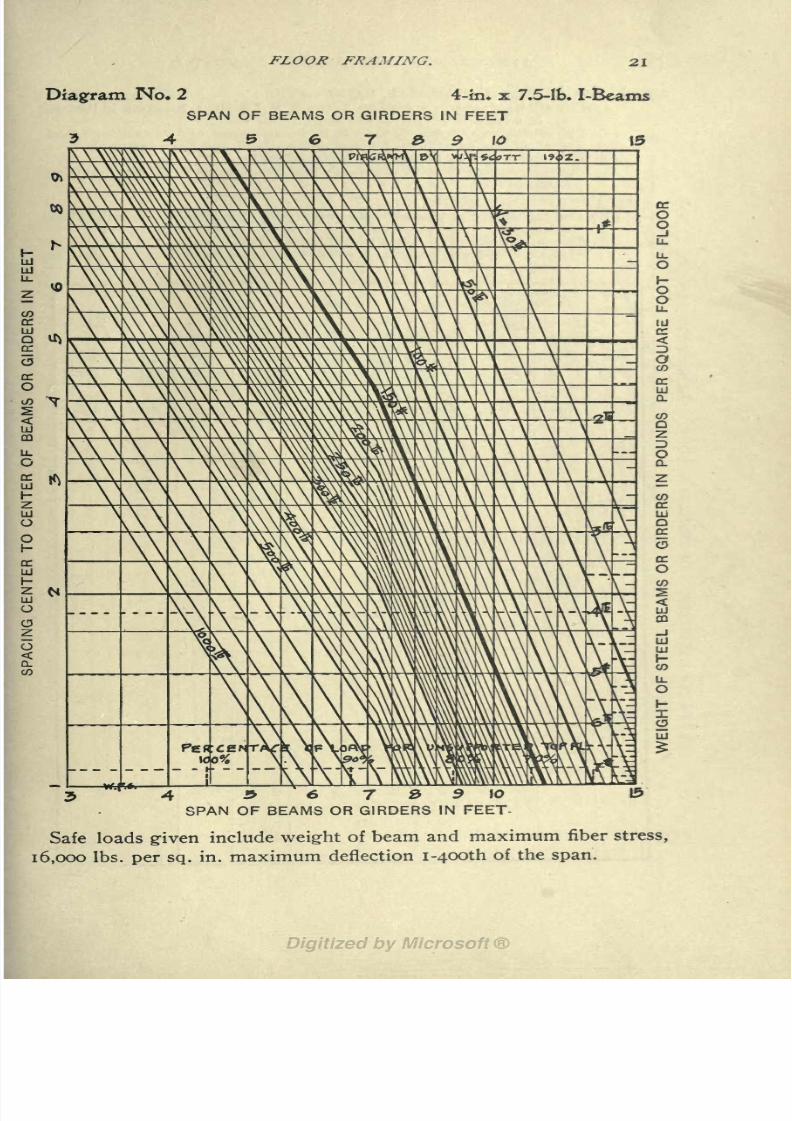
(a) The allowable uniform load on 4=in. x 7.5 Ib. I=bearns in Ibs. per
sq. ft. of floor.
(6) The allowable spacing C. to C. in ft. for any span and any uniform load.
(c) The allowable spanin ft. for
anyuniform load and
any spacing.(d) The weight of steel in Ibs. per sq. ft. of floor.
(^) The percentage of load allowable for any unsupported length of top
flange in feet.
THE TABLE FOLLOWING GIVES :
The percentage of load allowable on special shapes other than the above
standard.
The same percentage factor to be used for spacing instead of load.
The allowable end reaction for safety of web without reenforcement for
buckling.
4"!Beams
8/8/2019 Structural Design 00 Scot u of t
http://slidepdf.com/reader/full/structural-design-00-scot-u-of-t 34/177
FLOOR FRAMING. 21
Diagram No* 2 4-in. x 7.5-lb. I-Beams
SPAN OF BEAMS OR GIRDERS IN FEET
4 5 6 7 3 9 \Q
4 9~
6 7 9 9 1Q &SPAN OF BEAMS OR GIRDERS IN FEET
Safe loads given include weight of beam and maximum fiber stress,
16,000 Ibs. per sq. in. maximum deflection i-4OOth of the span.

8/8/2019 Structural Design 00 Scot u of t
http://slidepdf.com/reader/full/structural-design-00-scot-u-of-t 35/177
22 STRUCTURAL DESIGNERS' HANDBOOK.
THE DIAGRAM ON OPPOSITE PAGE GIVES :
(a) The allowable tmiform load on 5=in. x 9.75 Ib. I=beams in Ibs. per
sq. ft. of floor.
(ft) The allowable spacing C. to C. in ft. for any span and any uniform load.
(c) The allowable spanin ft. for
anyuniform load and
any spacing,(tf)
The weight of steel in Ibs. per sq. ft. of floor.
(e} The percentage of load allowable for any unsupported length of top
flange in feet.
THE TABLE FOLLOWING GIVES :
(_/) The percentage of load allowable on special shapes other than the above
standard.
() The same percentage factor to be used for spacing instead of load.
(Ji) The allowable end reaction for safety of web without reenforcement for
buckling.
5"!Beams

8/8/2019 Structural Design 00 Scot u of t
http://slidepdf.com/reader/full/structural-design-00-scot-u-of-t 36/177
FLOOR FRAMING.
Diagram No. 3
SPAN OF BEAMS OR GIRDERS
s
era
5-in. x 9.75-Ib,
IN FEET
9
I-Beams
-4 & e r 8 9 to
SPAN OF BEAMS OR GIRDERS IN FEET
Safe loads given include weight of beam and maximum fiber stress,
16,000 Ibs. per sq. in. maximum deflection i-4OOth of the span.

8/8/2019 Structural Design 00 Scot u of t
http://slidepdf.com/reader/full/structural-design-00-scot-u-of-t 37/177
STRUCTURAL DESIGNERS' HANDBOOK.
THE DIAGRAM ON OPPOSITE PAGE GIVES :
(a) The allowable uniform loadon 6=in. x 12.25 lb. I=beams in Ibs. per
sq. ft. of floor.
() The allowable spacing C. to C. in ft. for any span and any uniform load.
(c) The allowable span in ft. for any uniform load and any spacing,
(rf) The weight of steel in Ibs. per sq.ft.
of floor.
(e) The percentage of load allowable for any unsupported length of top
flange in feet.
THE TABLE FOLLOWING GIVES :
(/") The percentage of load allowable on special shapes other than the above
standard.
(grj The same percentage factor to be used for spacing instead of load.
(A) The allowable end reaction for safety of web without reenforcement for
buckling.
6"!Beams

8/8/2019 Structural Design 00 Scot u of t
http://slidepdf.com/reader/full/structural-design-00-scot-u-of-t 38/177
FLOOR FRAMING.
Diagram No. 4 6-in. x 12.25-11). I-Beams
SPAN OF BEAMS OR GIRDERS IN FEET
r & 9 10 15 20 23 30
7 8> 9 10 \5
SPAN OF BEAMS OR GIRDERS20
IN FEET
Safe loads given include weight of beam and maximum fiber stress,
16,000 Ibs. per sq. in. maximum deflection i-4OOth of the span.

8/8/2019 Structural Design 00 Scot u of t
http://slidepdf.com/reader/full/structural-design-00-scot-u-of-t 39/177
26 STRUCTURAL DESIGNERS' HANDBOOK
THE DIAGRAM ON OPPOSITE PAGE GIVES :
(a) The allowable uniform load on 7=in. x 15 Ib. I=beams in Ibs. per
sq. ft. of floor.
(>) The allowable spacing C. to C. in ft. for any span and any uniform load.
(c) The allowable span in ft. for any uniform load and any spacing.
(d) The weight of steel in Ibs. per sq. ft. of floor.
(^) The percentage of load allowable for any unsupported length of top
flange in feet.
THE TABLE FOLLOWING GIVES :
(_/) The percentage of load allowable on special shapes other than the above
standard.
(^) The same percentage factor to be used for spacing instead of load.
(/*) The allowable end reaction for safety of web without reenforcement for
buckling.
7"!
Beams

8/8/2019 Structural Design 00 Scot u of t
http://slidepdf.com/reader/full/structural-design-00-scot-u-of-t 40/177
FLOOR FRAMING. 27
Diagram No* 5 7-in* x J5-Ib. I-Beams
SPAN OF BEAMS OR GIRDERS IN FEET
7 & 9 10 \& 20 7.5
6 7 & 9 \0 \5 20SPAN OF BEAMS OR GIRDERS IN FEET
Safe loads given include weight of beam and maximum fiber stress,
16,000 Ibs. per sq. in. maximum deflection i-4OOth of the span.

8/8/2019 Structural Design 00 Scot u of t
http://slidepdf.com/reader/full/structural-design-00-scot-u-of-t 41/177
28 STRUCTURAL DESIGNERS' HANDBOOK
THE DIAGRAM ON OPPOSITE PAGE GIVES :
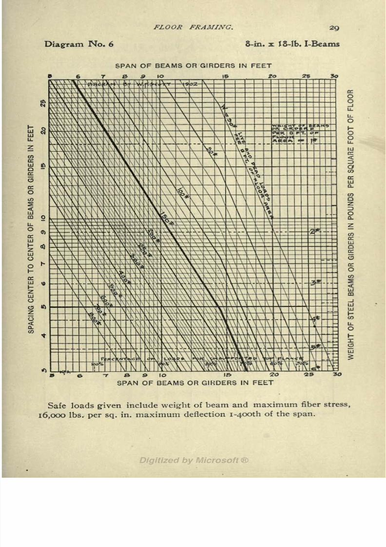
(a) The allowable uniform load on 8=in. x 18 Ib. I=beams in Ibs. per
sq. ft. of floor.
() The allowable spacing C. to C. in ft. for any span and any uniform load.
(c) The allowable span in ft. for any uniform load and any spacing.
(d) The weight of steel in Ibs. per sq. ft. of floor.
{e} The percentage of load allowable for any unsupported length of top
flange in feet.
THE TABLE FOLLOWING GIVES :
(f) The percentage of load allowable on special shapes other than the above
standard.
(^) The same percentage factor to be used for spacing instead of load.
(h) The allowable end reaction for safety of web without reenforcement for
buckling.
8"!
Beam-
8/8/2019 Structural Design 00 Scot u of t
http://slidepdf.com/reader/full/structural-design-00-scot-u-of-t 42/177
FLOOR FRAMING. 29
Diagram No. 6 8-in. x J8-lb. I-Beams
SPAN OF
9
BEAMS OR GIRDERS IN FEET
10 IB 2o 2* 30
S,
SPAN OF10 l> 20BEAMS OR GIRDERS IN FEET
30
Safe loads given include weight of beam and maximum fiber stress,
16,000 Ibs. per sq. in. maximum deflection i-4OOth of the span.

8/8/2019 Structural Design 00 Scot u of t
http://slidepdf.com/reader/full/structural-design-00-scot-u-of-t 43/177
30 STRUCTURAL DESIGNERS 1 HANDBOOK
THE DIAGRAM ON OPPOSITE PAGE GIVES :
(a) The allowable uniform load on 9=in. x 21 Ib. I=beams in Ibs. per
sq. ft. of floor.
(>) The allowable spacing C. to C. in ft. for any span and any uniform load.
(c) The allowable s$an in ft. for any uniform load and any spacing,
(rf) The weight of steel inIbs.
per sq.ft. of floor.
(e) The percentage of load allowable for any unsupported length of top
flange in feet.
THE TABLE FOLLOWING GIVES :
(_/) The percentage of load allowable on special shapes other than the above
standard.
(^) The same percentage factor to be used for spacing instead of load.
(/*) The allowable end reaction for safety of web without reenforcement for
buckling.
9"!Beam

8/8/2019 Structural Design 00 Scot u of t
http://slidepdf.com/reader/full/structural-design-00-scot-u-of-t 44/177
FLOOR FRAMING.
Diagram No. 7 9-in. x 2J-lb. I-Beams
SPAN OF BEAMS OR GIRDERS IN FEET
6 7 & 9 10 15 20 25
LU
LU
_ ..y D
\\\ \Pift\jfeHMN
yA--v^f L-&tr
\ \V\ \ \ A^V rAZllJ
1 2= Z
; o
=
"7 & S \O IB 10 Z& Z>0
SPAN OF BEAMS OR GIRDERS IN FEET
Safe loads given include weight of beam and maximum fiber stress,
16,000 Ibs. per sq. in. maximum deflection i-4OOth of the span.
8/8/2019 Structural Design 00 Scot u of t
http://slidepdf.com/reader/full/structural-design-00-scot-u-of-t 45/177
STRUCTURAL DESIGNERS' HANDBOOK.
THE DIAGRAM ON OPPOSITE PAGE GIVES :
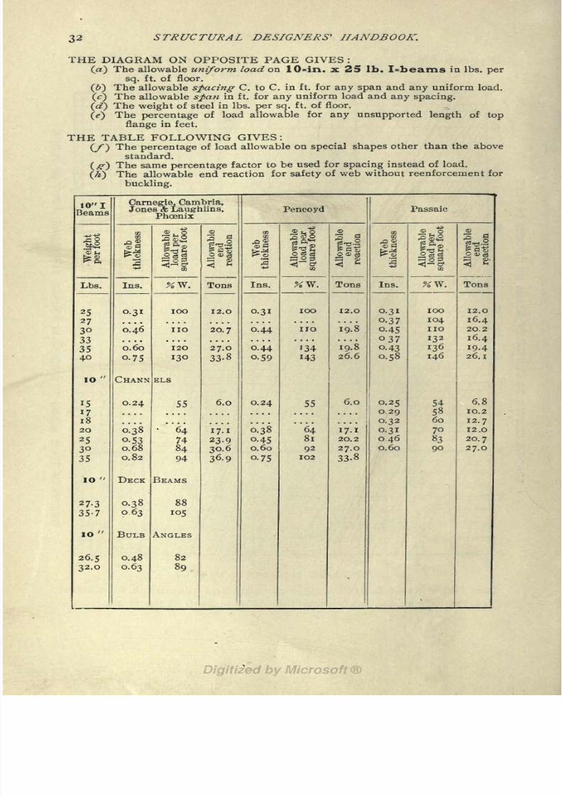
(a) The allowable uniform load on 10=in. x 25 Ib. I=beams in Ibs. per
sq. ft. of floor.
() The allowable spacing C. to C. in ft. for any span and any uniform load.
(c) The allowable span in ft. for any uniform load and any spacing.
(d) The weight of steel in Ibs. per sq. ft. of floor.
(<?)The percentage of load allowable for any unsupported length of top
flange in feet.
THE TABLE FOLLOWING GIVES :
(/) The percentage of load allowable on special shapes other than the above
standard.
( #) The same percentage factor to be used for spacing instead of load,
(/f) The allowable end reaction for safety of web without reenforcement for
buckling.
10"!Beams

8/8/2019 Structural Design 00 Scot u of t
http://slidepdf.com/reader/full/structural-design-00-scot-u-of-t 46/177
FLOOR FRAMING. 33
Diagram No. 8 JO-in. x 25-lb. I-Beams
SPAN OF BEAMS OR GIRDERS IN FEET
5 3 S 10 15 20SPAN OF BEAMS OR GIRDERS IN FEET
25 50
Safe loads given include weight of beam and maximum fiber stress,
16,000 Ibs. per sq. in. maximum deflection i-4OOth of the span.

8/8/2019 Structural Design 00 Scot u of t
http://slidepdf.com/reader/full/structural-design-00-scot-u-of-t 47/177
34 STRUCTURAL DESIGNERS' HANDBOOK.
THE DIAGRAM ON OPPOSITE PAGE GIVES :
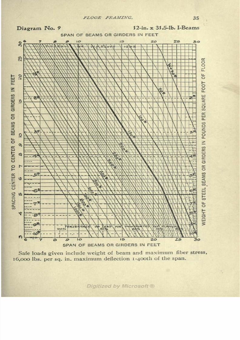
(a) The allowable uniform loadon 12=in. x 31.5 Ib. I=beams in Ibs. persq. ft. of floor.
(6) The allowable spacing- C. to C. in ft. for any span and any uniform load.
(c) The allowable span in ft. for any uniform load and any spacing.
(d) The weight of steel in Ibs. per sq. ft. of floor.
(e) The percentage of load allowable for any unsupported length of top
flange in feet.
THE TABLE FOLLOWING GIVES :
(/) The percentage of load allowable on special shapes other than the above
standard.
(XT) The same percentage factor to be used for spacing instead of load.
(/*) The allowable end reaction for safety of web without reenforcement for
buckling.
12"!
Beamv
8/8/2019 Structural Design 00 Scot u of t
http://slidepdf.com/reader/full/structural-design-00-scot-u-of-t 48/177
FLOOR FRAMING. 35
Diagram No* 9 f2-in*x 3J.5-lb. I-Beams
SPAN OF BEAMS OR GIRDERS IN FEET
a & 10 i 20 30
--\-\-XK-\-V\\\\\\IO IS 2O
SPAN OF BEAMS OR GIRDERS IN FEET
Safe loads given include weight of beam and maximum fiber stress,
16,000 Ibs. per sq. in. maximum deflection i-4OOth of the span.

8/8/2019 Structural Design 00 Scot u of t
http://slidepdf.com/reader/full/structural-design-00-scot-u-of-t 49/177
STRUCTURAL DESIGNERS' HANDBOOK.
THE DIAGRAM ON OPPOSITE PAGE GIVES :
(a) The allowable uniform load on 12=in. x 40 Ib. I=beams in Ibs. per
sq. ft. of floor.
() The allowable spacing C. to C. in ft. for any span and any uniform load.
(c)The allowable
spanin ft. for
anyuniform load and
any spacing.(d} The weight of steel in Ibs. per sq. ft. of floor.
(e) The percentage of load allowable for any unsupported length of top
flange in feet.
THE TABLE FOLLOWING GIVES :
(_/")The percentage of load allowable on special shapes other than the abovestandard.
( g} The same percentage factor to be used for spacing instead of load.
(h) The allowable end reaction for safety of web without reenforcement for
buckling.
12"!
Beams

8/8/2019 Structural Design 00 Scot u of t
http://slidepdf.com/reader/full/structural-design-00-scot-u-of-t 50/177
FLOOR FRAMING. 37
Diagram No* 10 J2-in. x 40-lb. I-Bcams
SPAN OF BEAMS OR GIRDERS IN FEET
9 \O \& 20
7 & 9 10 IB 20 25 30
SPAN OF BEAMS OR GIRDERS IN FEET
Safe loads given include weight of beam and maximum fiber stress,
16,000 Ibs. per sq. in. maximum deflection i-4OOth of the span.

8/8/2019 Structural Design 00 Scot u of t
http://slidepdf.com/reader/full/structural-design-00-scot-u-of-t 51/177
38 STRUCTURAL DESIGNERS' HANDBOOK.
THE DIAGRAM ON OPPOSITE PAGE GIVES :
(a) The allowable uniform load on 15=in. x 42 Ib. I=beams in Ibs. per
sq. ft. of floor.
(&) The allowable spacing- C. to C. in ft. for any span and any uniform load.
(c) The allowable span in ft. for any uniform load and any spacing.
(cT) The weight of steel in Ibs. per sq. ft. of floor.
(e) The percentage of load allowable for any unsupported length of top
flange in feet.
THE TABLE FOLLOWING GIVES :
(_/) The percentage of load allowable on special shapes other than the abovestandard.
(-) The same percentage factor to be used for spacing instead of load.
(Ji) The allowable end reaction for safety of web without reenforcement for
buckling.
15"!Beams

8/8/2019 Structural Design 00 Scot u of t
http://slidepdf.com/reader/full/structural-design-00-scot-u-of-t 52/177
FLOOR FRAMIXG. 39
Diagram No* \\
SPAN OF BEAMS OR GIRDERS IN FEET
5 20 25
15-in.x42-lb. I-Beams
O
o
10 15 20 25 30SPAN OF BEAMS OR GIRDERS IN FEET
Safe loads given include weight of beam and maximum fiber stress,
16,000 Ibs. per sq. in. maximum deflection i-4OOth of the span.

8/8/2019 Structural Design 00 Scot u of t
http://slidepdf.com/reader/full/structural-design-00-scot-u-of-t 53/177
40 STRUCTURAL DESIGNERS' HANDBOOK.
THE DIAGRAM ON OPPOSITE PAGE GIVES :
(a) The allowable uniform load on 15=in. x 60 Ib. I=beams in Ibs. per
sq. ft. of floor.
(>) The allowable spacing C. to C. in ft. for any span and any uniform load.
(<;)
The allowable
s$anin ft. for
anyuniform load and any spacing.
(a?)The weight of steel in Ibs. per sq. ft. of floor.
(e) The percentage of load allowable for any unsupported length of top
flange in feet.
THE TABLE FOLLOWING GIVES :
(y ) The percentage of load allowable on special shapes other than the above
standard.
(,>) The same percentage factor to be used for spacing instead of load.
(It) The allowable end reaction for safety of web without reenforcement for
buckling.
15"!
Beams

8/8/2019 Structural Design 00 Scot u of t
http://slidepdf.com/reader/full/structural-design-00-scot-u-of-t 54/177
FLOOR FRAMING.
Diagram No. J2 J5-in. x 60-lb. I-Beams
10
SPAN OF BEAMS OR GIRDERS IN FEET
15 20 30 50
= DC
- - O= O-u
^
- lu
a<
H '.
CD
O
3n-n oc
LU
= z
IT O
(0
Ld
CO
IO 15 2O 2^ 3O -4-^
SPAN OF BEAMS OR GIRDERS IN FEET
Safe loads given include weight of beam and maximum fiber stress,
16,000 Ibs. per sq. in. maximum deflection i~4OOth of the span.
8/8/2019 Structural Design 00 Scot u of t
http://slidepdf.com/reader/full/structural-design-00-scot-u-of-t 55/177
STRUCTURAL DESIGNERS 1 HANDBOOK.
THE DIAGRAM ON OPPOSITE PAGE GIVES:
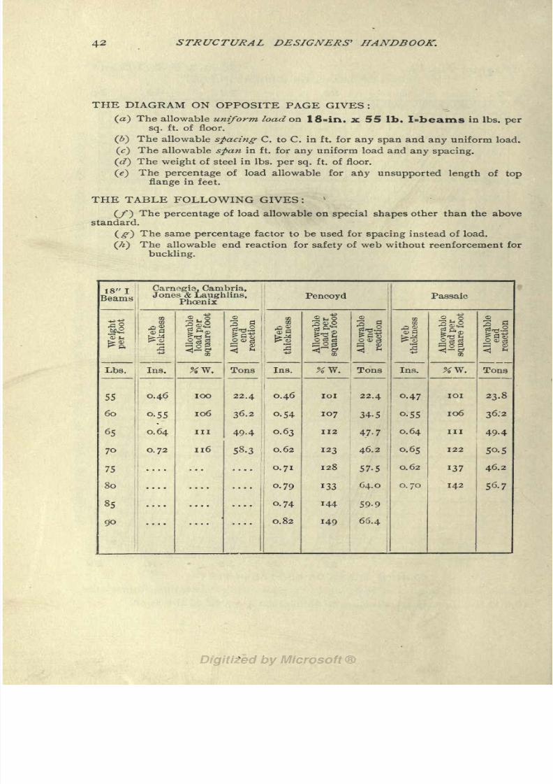
(a) The allowable uniform load on 18=in. x 55 Ib. I=beams in Ibs. per
sq. ft. of floor.
(b) The allowable spacing C. to C. in ft. for any span and any uniform load.
(c) The allowable span in ft. for any uniform load and any spacing.
(cT) The weight of steel in Ibs. per sq. ft. of floor.
(<?)The percentage of load allowable for any unsupported length of top
flange in feet.
THE TABLE FOLLOWING GIVES:
(/") The percentage of load allowable on special shapes other than the abovestandard.
(-) The same percentage factor to be used for spacing instead of load.
(/*) The allowable end reaction for safety of web without reenforcement for
buckling.
18"!Beams

8/8/2019 Structural Design 00 Scot u of t
http://slidepdf.com/reader/full/structural-design-00-scot-u-of-t 56/177
FLOOR FRAMING. 43
Diagram No* J3 18-in.x 55-lb. I-Eeams
SPAN OF BEAMS OR GIRDERS IN FEET
lo 2o 30 40 So
_. _ Q
- ou_
_ UJ
. II a:
O
09
DC
HI
Qd QC
O
H O05
LJ
CO
10 -405 20 25 30
SPAN OF BEAMS OR GIRDERS IN FEET
Safe loads given include weight of beam and maximum fiber stress,
16,000 Ibs. per sq. in. maximum deflection i-4OOth of the span.
8/8/2019 Structural Design 00 Scot u of t
http://slidepdf.com/reader/full/structural-design-00-scot-u-of-t 57/177
44 STRUCTURAL DESIGNERS' HANDBOOK.
THE DIAGRAM ON OPPOSITE PAGE GIVES:
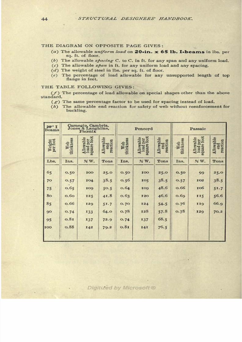
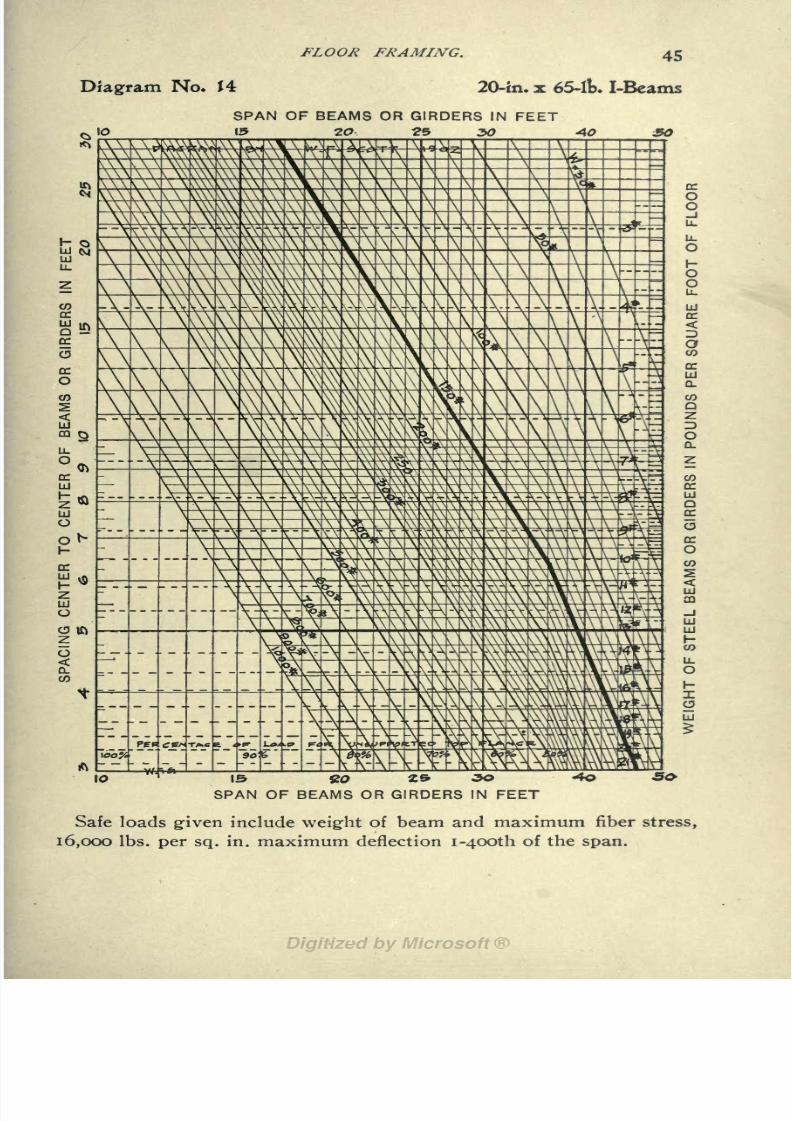
(a) The allowable uniform load on 20=in. x 65 lb. I-beams in Ibs. per
sq. ft. of floor.
() The allowable spacing C. to C. in ft. for any span and any uniform load.
(<:)The allowable span in ft. for any uniform load and any spacing.
(c?)The weight of steel in Ibs. per sq. ft. of floor.
(e) The percentage of load allowable for any unsupported length of top
flange in feet.
THE TABLE FOLLOWING GIVES :
The percentage of load allowable on special shapes other than the above_
standard.
The same percentage factor to be used for spacing instead of load.
The allowable end reaction for safety of web without reenforcement for
buckling.
20"!Beams
8/8/2019 Structural Design 00 Scot u of t
http://slidepdf.com/reader/full/structural-design-00-scot-u-of-t 58/177
FLOOR FRAMING. 45
Diagram No. 14 20-in.x65-lkl-Beams
SPAN OF BEAMS OR GIRDERS IN FEET13 2O 25 30 AO
....
I"" O
10
OF BEAMS OR GIRDERS IN FEET
Safe loads given include weight of beam and maximum fiber stress,
16,000 Ibs. per sq. in. maximum deflection i-4OOth of the span.

8/8/2019 Structural Design 00 Scot u of t
http://slidepdf.com/reader/full/structural-design-00-scot-u-of-t 59/177
46 STRUCTURAL DESIGNERS' HANDBOOK.
THE DIAGRAM ON OPPOSITE PAGE GIVES:
(a) The allowable uniform load on 24=in. x 80 Ib. I=beams in Ibs. per
sq. ft. of floor.
(>) The allowable spacing C. to C. in ft. for any span and any uniform load,
(c) The allowable span in ft. for any uniform load and any spacing.
(W) The weight of steel in Ibs. per sq. ft. of floor,
(tf)The percentage of load allowable for any unsupported length of top
flange in feet.
THE TABLE FOLLOWING GIVES :
(/) The percentageof load allowable on
special shapesother than the above
standard.
(^) The same percentage factor to be used for spacing instead of load,
(/f) The allowable end reaction for safety of web without reenforcement for
buckling.
24"!Beams
8/8/2019 Structural Design 00 Scot u of t
http://slidepdf.com/reader/full/structural-design-00-scot-u-of-t 60/177
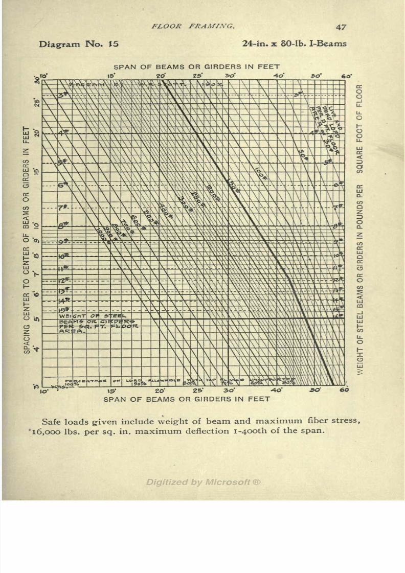
FLOOR FRAMING. 47
Diagram No. J5 24-in. x 80-lb. I-Beams
SPAN OF BEAMS OR GIRDERS IN FEET
15' 20 25 "bo' 40 SO" 60'
10 20'
SPAN OF BEAMS
&' 3O* -4O'
OR GIRDERS IN FEET
Safe loads given include weight of beam and maximum fiber stress,
'16,000 Ibs. per sq. in. maximum deflection i-4OOth of the span.

8/8/2019 Structural Design 00 Scot u of t
http://slidepdf.com/reader/full/structural-design-00-scot-u-of-t 61/177
48 STRUCTURAL DESIGNERS' HANDBOOK
Diagrams Nos. 16, 17, 18, 19, 20 and 21
FOR GIVING:
(a) The allowable uniformly distributed live and dead load, on Anglesand Tees, as beams or girders, in pounds per square foot of floor.
(&) The allowable spacing, center to center, for any span and any uniform
loading.
(c) The allowable span in feet for any uniform loading and any spacing.

8/8/2019 Structural Design 00 Scot u of t
http://slidepdf.com/reader/full/structural-design-00-scot-u-of-t 62/177
FLOOR FRAMING. 49
Diagram No* J8

8/8/2019 Structural Design 00 Scot u of t
http://slidepdf.com/reader/full/structural-design-00-scot-u-of-t 63/177
SJ^RUCTURAL DESIGNERS' HANDBOOK.

8/8/2019 Structural Design 00 Scot u of t
http://slidepdf.com/reader/full/structural-design-00-scot-u-of-t 64/177
FLOOR FRAMING.
O "-1 "-1 MVO t>oo O
OOOO OOt^N ONOO
iot4o\M in.Jo.c5cN
III
8 Z
SPACING IN FEET
8/8/2019 Structural Design 00 Scot u of t
http://slidepdf.com/reader/full/structural-design-00-scot-u-of-t 65/177
52 STRUCTURAL DESIGNERS' HANDBOOK'.
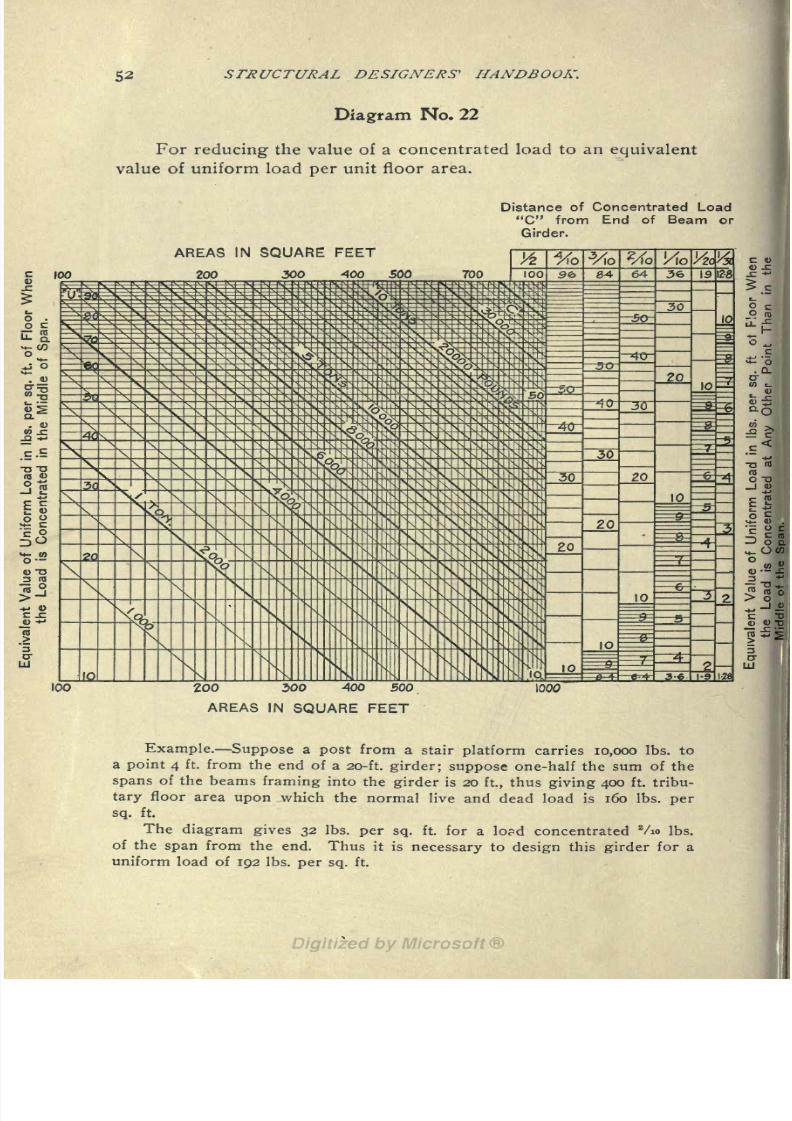
Diagram No* 22
For reducing the value of a concentrated load to an equivalent
value of uniform load per unit floor area.
Distance of Concentrated Load
"C" from End of Beam or
Girder.
AREAS IN SQUARE FEET
200 300 AOQ 500
200 300 400 500
AREAS IN SQUARE FEET
1000
Example. Suppose a post from a stair platform carries 10,000 Ibs. to
a point 4 ft. from the end of a 20-ft girder; suppose one-half the sum of the
spans of the beams framing into the girder is 20 ft, thus giving 400 ft. tribu-
tary floor area upon which the normal live and dead load is 160 Ibs. per
sq. ft.
The diagram gives 32 Ibs. per sq. ft. for a load concentrated Vio Ibs.
of the span from the end. Thus it is necessary to design this girder for a
uniform load of 192 Ibs. per sq. ft.

8/8/2019 Structural Design 00 Scot u of t
http://slidepdf.com/reader/full/structural-design-00-scot-u-of-t 66/177
CHAPTER IV. SPANDREL BEAMS.
The diagrams and tables given in Chapter III on beams used
in floor framing cover the large majority of cases of beamwork
arising in building design. Numerous cases arise, however, in
connection with building work in which beams are required to
carry loads that are not reduced to the same unit load as in floor
design. These are various but will be classed, for convenience,
under the head of spandrel beams.Spandrel beams carry a variety of loads ranging from contin-
uous curtain walls and individual piers to extraneous loads from
balconies and the like. Two or more of these loads may be com-
bined on the same beam.
A system is herewith presented for the design of such beams.
It calls for a minimum expenditure of time and insures a high de-
gree of safety in the solution of this problem. The distinguishing
feature of the system is the method of considering a concentrated
load for any position it may have upon the beam. For a load uni-
formly distributed or a load concentrated at the middle of a beam,
the system differs but slightly from the ordinary methods, as will
be seen by referring to the explanation of Diagrams Nos. 24, 25
and 26.
As explained in Chapter I under "Loads on Beams," the effect
of a load concentrated at any other point than the middle is less
than the effect of the same load if concentrated at the middle of the
beam. Evidently therefore, there is always an equivalent reducedload that will have the same effect on a beam when concentrated at
the middle as the actual load when concentrated at any other point.
This equivalent reduced load is given on Diagram No. 23 and the
method of obtaining it will be understood from the following:
EQUIVALENT LOAD DIAGRAM. In this Diagram No. 23,
the abscissas represent the position of the load, and the ordinates
represent equivalent load. The actual concentrated load is shown
as a curvedline,
and theposition
of the load is
given
in various
ways. At the top of the diagram the abscissa scale shows the dis-
tance of the load from the end of the beam as a fraction of the
(53)

8/8/2019 Structural Design 00 Scot u of t
http://slidepdf.com/reader/full/structural-design-00-scot-u-of-t 67/177
54 STRUCTURAL DESIGNERS' HANDBOOK.
span. At the bottom of the diagram the distance from the load
to the end of the beam is given in feet in different scales for various
spans from 10 to 26 ft. The ordinate scale gives the equivalent
load concentrated at the middle.To use the diagram, take an abscissa representing the distance
of the load from the end of the beam (selecting one of the foot
scales for the given span, or else using the fraction scale at the
top of the diagram) and follow up to the curved line representing
the load. Follow the horizontal at the intersection reading equiva-
lent reduced middle concentrated load.
The diagram also has a horizontal scale showing the reaction
at the end nearest to the load, in per cent, of the actual concen-trated load. This value of reaction is to be used in investigating
the end shear or tendency of the web to buckle by comparing with
the maximum allowable end shear on any beam, as given in the
tables in Chapter VIII, or as given in the supplementary tables in
Chapter III. The subject of end reactions is treated more fully in
Chapter VI.
DIAGRAMS FOR SAFE LOADS ON I-BEAMS AND CHANNELS.
The Diagrams Nos. 24, 25 and 26 are for the design of miscel-laneous beams and girders conveniently classed under the head of
spandrel beams. If time was not an important item in the design
of beamwork, these diagrams could take the place of those preced-
ing them, for they are adapted for general application.
The method of using these diagrams will be clear. In each of
the three diagrams, the abscissas represent span of beam in feet,
while the ordinates represent uniform total load, or total load con-
centrated at the middle. The diagonal lines represent the differentsizes of I-beams and channels. The smaller sizes of I-beams are
shown on Diagram No. 24, while the larger sizes, i5-in. and over
are shown on Diagram No. 25. All sizes of channels are shown on
Diagram No. 26. The heavy full diagonal lines on these diagrams
show the ''standard" sections of different sizes;the light full line
show the special sections. As will be understood, the change in
direction of the lines is due to the deflection entering as a limiting
factor above a certain span. The reason for the presence of dottedlines parallel to these lines will be given in Note 2.
In these diagrams also, the left hand portion of the lines, that deter-
mined by the allowable fiber stress, is continued as a dotted line beyond the
point where deflection enters as a factor. This dotted continuation can be
used when a beam is to be designed without reference to deflection.

8/8/2019 Structural Design 00 Scot u of t
http://slidepdf.com/reader/full/structural-design-00-scot-u-of-t 68/177
SPANDREL BEAMS. 55
To use the diagrams take an abscissa equal to the span, the
ordinate (on the proper scale, either for load uniformly distributed
or concentrated at the middle) equal to the load, and the section to
be used is read off on the diagonal at the intersection. Obviously,
the diagram may also be used to give maximum load or maximum
span for any given section of I-beam or channel, on a given span
or under a given load, respectively.
NOTE I. The special 15-in. I-beams run up among the i8-in. and 2O-in.
I-beams, but to discriminate it is only necessary to note the point of de-
flection of the lines. The same rule applies to the diagram for channels.
NOTE 2. If the loads on a beam or girder consist of comparatively
light concentrations on top of a well distributed uniform load, it is advisa-
ble to reduce the concentrated loads to an equivalent uniformloading.
The reason for this will be evident from the following: As the span in
inches of a steel beam which is uniformly loaded increases above 21.75 times
its depth in inches, the maximum fiber stress begins to decrease from
16,000 Ibs. per sq. in. if designed for a limiting deflection of one four-hun-
dredth of the span. In the case of a load concentrated in the middle, the de-
crease does not begin to take place until the span is 27.2 times the depth, or
il/4 times that for uniform loading.
On Diagrams Nos. 24, 25 and 26, this difference in safe deflection is
shown graphically by dotted lines for beams with uniform loading and by
full lines for beams with load concentrated in the middle.
NOTE 3. When large concentrated loads occur at both ends of a
beam the diagrams should not be used. Use tables in Chapter VIII.
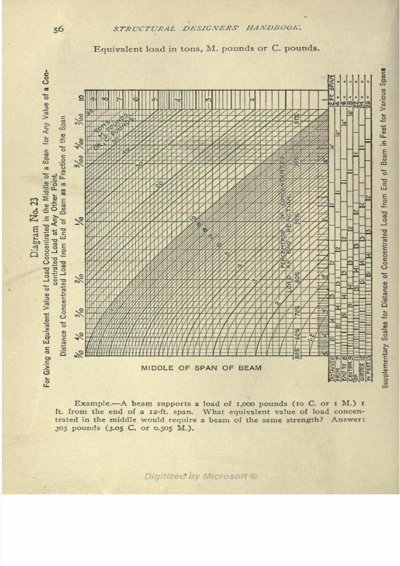
8/8/2019 Structural Design 00 Scot u of t
http://slidepdf.com/reader/full/structural-design-00-scot-u-of-t 69/177
56 STRUCTURAL DESIGNERS' HANDBOOK.
Equivalent load in tons, M. pounds or C. pounds.
MIDDLE OF SPAN OF BEAM
Example. A beam supports a load of 1,000 pounds (10 C. or i M.) I
ft. from the end of a 12-ft. span. What equivalent value of load concen-
trated in the middle would require a beam of the same strength? Answer:
305 pounds (3.05 C. or 0.305 M.).

8/8/2019 Structural Design 00 Scot u of t
http://slidepdf.com/reader/full/structural-design-00-scot-u-of-t 70/177
SPANDREL BEAMS. 57
Diagram No. 24.
For giving the allowable load on standard and special I-beams.
SPAN IN FEET
O I?
SPAN IN FEET
The deflection curves are shown by full lines for loading concen-
trated in the middle and dotted lines for uniformly distributed; thus a
6-in. x i21/4-lb. beam with a span of 15 ft. will carry 1.15 tons concentrated
in the middle or 1.85 tons uniformly distributed.

8/8/2019 Structural Design 00 Scot u of t
http://slidepdf.com/reader/full/structural-design-00-scot-u-of-t 71/177
STRUCTURAL DESIGNERS' HANDBOOK.
Diagram No. 25
For giving the allowable load on standard and special I-beams.
SPAN IN FEET
SPAN IN FEET
Example. A 20-in. x65-lt). beam 42-ft. span will carry 7.35 tons con-
centrated in the middle of the span or 12.35 tons uniformly distributed.

8/8/2019 Structural Design 00 Scot u of t
http://slidepdf.com/reader/full/structural-design-00-scot-u-of-t 72/177
SPANDREL BEAMS.
Diagram No. 26
59
For giving the allowable load on standard and special channels.
SPAN IN FEET
SPAN IN FEET
Example. A 12-in. x 20.5-lb. beam 24-ft. span will carry 2.35 tons con-
centrated in the middle of the span or 4.2 tons uniformly distributed.

8/8/2019 Structural Design 00 Scot u of t
http://slidepdf.com/reader/full/structural-design-00-scot-u-of-t 73/177
60 STRUCl'URAL DESIGNERS' HANDBOOK.
CHAPTER V. GRILLAGE BEAMS.
FOOTINGS. The use of steel beams in footings is a problem of
frequent occurrence with the structural designer. This chapter
deals with the design of the steel beams for grillage footings and
presupposes a general acquaintance with the subject of founda-
tions* on the part of the reader.
Grillage footings are in general either footings of walls or foot-
ings of columns. The former are somewhat the simpler in design,
but their treatment is precisely the same as that for column foot-
ings. They will therefore not be especially referred to in the fol-
lowing. When two or more columns occur on a single footing
the problem, on the other hand, becomes so complex that only
those familiar with the mechanics of engineering should presume to
deal with it. The properties of beams as given in Chapter VIII
may be used for this latter case.
The known quantities in the design of a footing are the load
on the column and the allowable pressure per unit area on the soil
(or other material) which supports the grillage. The area of the
surface of a footing which comes in contact with the soil is found
by dividing the load on the footing by the allowable pressure, on the
soil.
The accompanying drawing, Fig. 2, shows a design of a grill-
age footing for a single column having two tiers of grillage. From
this drawing the elements of the design of the different tiers of
beams may readily be understood. The load on the column is
transferred to the grillage by a "base," of cast iron or of steel, and
the size of this base must be known or assumed before the grillage
beams can be designed.
DESIGN OF GRILLAGE BEAMS.
BENDING. As explained in the short treatment on the "Con-
ventional Methods of Considering Loads on Grillage Beams" in
Chapter I there are two methods of designing these beams.
The most common method is to consider only the projecting
length of these beams beyond the edge of the tier or base imme-
*For this aspect of the subject such books as Baker's Treatise on
Masonry Construction; Kidder's Building Construction and Superin-
tendence, Part I; and Pattern's Practical Treatise on Foundations, and the
back files of the Engineering News and Engineering Record should be
consulted.

8/8/2019 Structural Design 00 Scot u of t
http://slidepdf.com/reader/full/structural-design-00-scot-u-of-t 74/177
GRILLAGE BEAMS. 61
diately above them. Within certain limits this method will give
satisfactory results. It will always give safe results ifb/2a does not
exceed 0.3, where b equals the breadth of the base or tier
above, and a equals the projection of the beams beyond the edgeof this base (2a + b) equals the entire length of the grillage beamunder consideration.
The second method is more conservative although the follow-
ing is a modification of it by 30% limit allowance for the value
"

8/8/2019 Structural Design 00 Scot u of t
http://slidepdf.com/reader/full/structural-design-00-scot-u-of-t 75/177
62 STRUCTURAL DESIGNERS' HANDBOOK.
While the bending is the main item that determines the
strength of grillage beams, one other determinative factor should
not be neglected:
BUCKLING OF THE WEB. The following is practically an
empirical method of ensuring the safety of the webs of grillage
beams against buckling. Here again the concrete is undoubtedly
a factor in the strength of the webs, but as it is probably very slight,
its influence is not considered. Tables in Chapter VIII give values
in tons per lineal foot of I-beams for the allowable load per lineal
foot that can be placed on such a beam. These values were com-
puted according to the "Code" on the basis of the assumption that
the safe load on the flange of one lineal foot of beam could be
taken as a safe unit working load per foot for the total length of
beams directly under the base.
NOTE. The flanges of nearly all rolled beams are usually a little
higher on one side than on the other, thus there is a slight tendency for
eccentricity of loading on the web. It is therefore advisable to be liberal
in the use of separators between grillage beams, especially directly under
the edges of the tier above.
DIAGRAM FOR GRILLAGE BEAMS. The makeup
of Dia-
gram No. 27 is quite simple. Abscissas represent span ;i. e., pro-
jecting portion of beams (symbol "a") and ordinates represent the
safe loads; diagonal lines represent the different sizes and weights
of beams. The safe loads are expressed in tons per square foot of
area, and therefore different ordinate scales are necessary for dif-
ferent spacings of beams. These suitable scales are shown at the
left and right of the diagram, so that 8, 10, 12, 14 or i6-in. spacing
of beams arerepresented
the scale
givenon the
diagram properis for i2-in. spacing, while the other scales are found at the sides.
NOTE i. The loads on grillage beams vary inversely as the spacing of
the beams, for instance, suppose 2O-in. spacing was desired, evidently half
the load given in the diagram for 10-in. spacing will give the correct size
of beam for 2O-in. spacing.
NOTE 2. The full heavy lines on the diagram are for the standard
minimum weight I-beams, and the fine lines for other weights. These lines
give values on a basis of 16,000 Ibs. per sq. in. max. fiber stress. The
dotted lines produced from the right hand portions of the curves, at the
bend of the curves, give values for the standard minimum weight I-beams
on a basis of a fiber stress of 20,000 Ibs. per sq. in. and a limiting deflection
of one five-hundredth of the span.
NOTE 3. The limiting values for the pressure on mortar and con-
crete are indicated by dotted lines across the diagram. It is advisable to
keep well below these limits.

8/8/2019 Structural Design 00 Scot u of t
http://slidepdf.com/reader/full/structural-design-00-scot-u-of-t 76/177
Diagram No* 27
For giving size, weight and spacing of I-beams necessary for
each of the several tiers in a grillage footing.
PROJECTION OF GRILLAGE BEAMS IN FEET
Example. Grillage beams 10 ins. x 25 Ibs. projecting 3 ft. and spaced 8ins. c. to c. are good for 5.4 tons per square foot; 10 ins. c. to c., 4.3 tons;12 ins., 3.6 tons; 14 ins., 3.1 tons, and 16 ins., 2.7 tons. (See text.)
(63)

8/8/2019 Structural Design 00 Scot u of t
http://slidepdf.com/reader/full/structural-design-00-scot-u-of-t 77/177
64 STRUCTURAL DESIGNERS' HANDBOOK.
To use the diagram for the design of grillage beams, take an
abscissa to represent the projection of the beams in feet, an ordi-
nate equal to the load per square foot, using either the ordinate
scale in the diagram proper or the supplementary scales, and fol-
low to an intersection. The diagonal line nearest above this inter-
section gives the size and weight of beam.
In preliminary work several spacings of beams should be as-
sumed and the resulting size of beam obtained for the conditions
of load and span already determined. A rough calculation of the
weights of the beams will then indicate the most economical for the
design.
Example. Suppose a grillage footing is to be designed for a- column
carrying a total load of 400 tons, where the soil will bear a safe loading of
4 tons per sq. ft.; suppose the cast-iron base of the column is 4 ft. square.
The bottom tier would then be 10 x 10 ft. (100 sq. ft. in area), and the next
tier 4 x 10 ft. (40 sq. ft.), which would give 10 tons per sq. ft. pressure upon
it. The projection of the beams will be 3 ft. in both cases.
SOLUTION BY IST METHOD. Using Diagram No. 27. The beams re-
quired for a span of 3 ft. and 4 ton loading may be lo-in. 25-lb. I s, spaced
about lo-in. c. to c., giving 12 beams to the tier, or 12-in. 31^ Ib. I sspaced
about i6-in. c. to c.,
giving8 beams to the tier. Thus
2,560Ibs. of steel is
needed if 12-in. beams are used, and 3,000 Ibs. if the lo-in. are used.
For the next tier, i5-in.42-lb. I s can be spaced lo-in. c. to c., i.e., 5 beams
are required (2,100 Ibs.), or i8-in. 55-lb. I s, spaced i6-in. c. to c., i. e., 3
beams (2,200 Ibs.) to the tier.
SOLUTION BY 2D METHOD. (A) Using formula (20). The beams
should only be spaced 78% of that given by the diagram. Thus, the lo-in I s
should be% 7.8-in. c. to c., the 12-in. I s i2.5-in. c. to c.
;for the next tier the
15-in. Is 7.8-in. c. to c. and the i8-in. Is i2.5~in. c. to c.
(B) Or using formula (21) the number of beams should be 137% of
those given by the first method. That is, instead of 12 and 8 beams for the
first tier, there should be 16 and n, and for the next tier, instead of 5 and
3 there should be 7 and 4 beams.
SOLUTION FOR BUCKLING OF THE WEBS. The tier of beams directly
under the base of the column always presents the most unfavorable condi-
tions. This cast-iron base is 4 ft. square. By dividing the load (400 tons)
on the footing by the length of the base, and the quotient by the number
of beams in the tier, the load on each lineal foot of beam is obtained.
Thus, on the 15-in. beams (considering the first method of design), this
load is 20 tons, and for the i8-in. beams the load is
33.3tons.
Byreferring
to the tables in Chapter VIII it will be found that the allowable load on the
12-in. beams is 22.3 tons, while the i8-in. beams only carry 23.4 tons. In
the latter case it is evident that it would be impracticable to use these
three beams.

8/8/2019 Structural Design 00 Scot u of t
http://slidepdf.com/reader/full/structural-design-00-scot-u-of-t 78/177
END REACTIONS. 65
CHAPTER VL END REACTIONS.
The effect of the end reaction on the strength of a beam hasbeen discussed in Chapter I
;the cause and effect of an end reaction
was referred to in Chapters III and IV; while this chapter briefly
outlines the subject of end reactions as considered by the struc-
tural designer in deciding upon the relative value of standard and
special details of construction, and in deciding upon the design of
these standard or special details.
Standard details materially reduce the cost of structural work,
and so long as thereis
a balance of savingin
shop workto
payfor
the excess material required by their use, they should be adopted.
On the other hand, the most liberal standards are not safe beyond
partially defined limits and these limits should be carefully checked.
It is hoped this treatment of the subject will be of value in keeping
a proper balance between these conflicting conditions.
From the following description it will be seen that Dia-
gram No. 28, gives the end reaction, due to uniformly loading a
beamof
any spanso as to
developits full
working strength.It also
gives equivalent values for area of a bearing plate or number of riv-
ets required for a pair of connection angles.
DIAGRAM NO. 28. This diagram covers cases of end re-
actions on beams under uniform loads. The abscissas represent
span of beam, orclinates represent end reaction and diagonal lines
represent the different sizes of I-beams and channels. The quanti-
ties referred to are all found on the central part, or diagram proper.
To the left and right will be found alternative sets of ordinate
scales, applying directly to the diagram which give the essential
values concerning riveted end connections and bearing plates.
The six scales to the left of the diagram show the number of f-in.
rivets, in shear, required to take care of a reaction of any given
amount. Steel and wrought iron shop rivets, field rivets and bolts
are represented by the six columns. The two columns at the right
of the diagram should be used in connection with these; they
show the number of }-in rivets,in
bearing ona
web i/io-in. thick,
required for any reaction. These values are also given for steel
and wrought iron rivets. At the right of the latter scales is another
set of ordinate scales applying to bearing plates (often called tem-
plates). They show the area (in square inches) of bearing plate

8/8/2019 Structural Design 00 Scot u of t
http://slidepdf.com/reader/full/structural-design-00-scot-u-of-t 79/177
66 STRUCTURAL DESIGNERS* HANDBOOK.
required for any reaction, in five columns, calculated on a basis of
18 tons, 15 tons, 5 tons and 8 tons permissible loadings per squarefoot. The usual sizes of bearing plates are given in the last column
to theright,
at
properintervals to
representtheir area in
squareinches.
To use the diagram and auxiliary scales for any particular
problem, take an abscissa representing the span in feet, and follow
along the vertical to the intersection with the diagonal representing
the size of I-beam or channel used. The horizontal at the inter-
section, if followed to the reaction scale at the left of the diagram,
gives the actual reaction in tons. Following the same horizontal
farther to theleft,
the number of rivets(or bolts) required
in shear
is found in the appropriate column. The same horizontal followed
out to the right shows the number of rivets required for bearing
on i/io in. of web. This number is to be divided by the actual
thickness in tenths of an inch of the metal, and the quotient then
represents the number of rivets required for bearing.
In case the end of the beam rests on a bearing plate, the
horizontal line is followed out to the scales "Sizes of Templates,"
and onthe
appropriatescale
(asdescribed
below)the
requiredarea
in square inches is read off.
NOTE. For spans other than those given on the diagrams the re-
action is given by the following rule: For any given size of beam, the
end reaction varies inversely as the span.
Example. The end reaction on a lo-in. 25-lb. I-beam, lo-ft. span, loaded
to its full capacity, is 6 T/2 tons. If the span were 30 ft. the reaction would
be one-third of 6 l/ ,or 2.2 tons.
The valises to be obtained from the diagram just described
are used in the design of connection angles and bearing plates,
along with the following table and diagram.
DESIGN OF CONNECTION ANGLES.
STANDARD CONNECTION ANGLES: The sizes of angles used
for "standards" are closely represented by the following list:
For 18" Is For 15" Is and chan-
and over. nels and under.
Passaic, Carnegie, Cambria, Jones & L. 4 X4 x^ 6 X4 x^Pencoyd 4 x 3
l/2 x Vie 6 x 3^xVi
Am. Bridge 4 X 4 * v" 6 X 4 xVi.
Anonymous 3^ x 3^ * 3/& 3
1A x 3% x6Ae

8/8/2019 Structural Design 00 Scot u of t
http://slidepdf.com/reader/full/structural-design-00-scot-u-of-t 80/177
END REACTIONS. 67
The lengths of standard angles for the several sizes of beams
are usually as follows :
For 24" Is i' 6" 1 g. For . .10" to 7" I* and O o' 5" 1 g."
20" and 18" i' 3""
. . 6" o' 3""
15" I s and [s o' 10" " "..5" o' 2^"
"
"12" Is and [s o' 7J4"
" ". . 4" and 3" o' 2"
The numbers of shop and field rivets in the above standards
do not vary very much, although Pencoyd and the American Bridge
Co. put in one extra shop rivet in the I5~in. and in the lo-in. to 7-in.
standards over what is called for in the same standards in the fol-
lowing table.
The strength of a pair of connection angles (sometimes called
knees) not only depends upon the number and strength of the rivets
in them, but also upon the strength of the metal upon which the
rivets bear. These values for both standard and special connection
angles are given in the following table.
TABLE GIVING MAXIMUM ALLOWABLE END REACTIONON STANDARD AND SPECIAL CONNECTION ANGLES: This
table (No. 16) gives the maximum load that can be safely
carried by different standard and special connection anglesin terms of the strength of the shop and field rivets in shear
or bearing. Evidently, the end reaction on the beam must not be
greater than these values for shear or for bearing. The tabular
values are for safe shearing capacity (single shear) and safe bear-
ing capacity (for bearing on 1/10-in. metal in web). The construc-
tion of the table needs no further explanation. Whenever there
is reason to suspect that a standard connection will not be sufficient
for conditionsindicated
by DiagramNo.
28,the
capacityof this
standard should be found from the table. The use of this table
is best illustrated by an example.
Example: A 12-in. 31.5 Ib. I-beam has lo-in. beams i6 l/ ft. long framing
into it from both sides. The web of the 12-in. girder is 0.35 in. thick, thus
giving a bearing value of o.i75-in. for each field connection. Suppose,
wrought iron rivets are used in the field, the permissible end reaction would
then be 0.175 x 2.26, or 3.95 tons. According to Diagram No. 28 this is the
safe limit for uniformly loading the lo-in. beams.
In designing special connection angles their length is limited
by the clear distance between the fillets of the beam. This dis-
tance is given for all I-beams and channels in the tables given in
Chapter VIII.
On general principles it is advisable to use as large connection
8/8/2019 Structural Design 00 Scot u of t
http://slidepdf.com/reader/full/structural-design-00-scot-u-of-t 81/177
68 STRUCTURAL DESIGNERS' HANDBOOK.
angles as practicable, because they add stiffness to the framing.
This is especially of value in high buildings,
DESIGN OF BEARING PLATES.
The elements in the design of a bearing plate or template are
its bearing area and its thickness.
The bearing area depends upon the load to be carried (the end
reaction) and upon the permissible unit load on the material sup-
porting the template. This latter is specified in the "Code" (N.
Y. C.) as follows :
On Brickwork:8 tons per sq. ft. when lime mortar is used;
15 tons per sq. ft. when cement mortar is used;
18 tons per sq. ft. when Portland cement (i to 3) is used.
For Rubble Masonry:
5 tons per sq. ft. when lime mortar is used.
These values will be found to be the column headings for tem-
plates in Diagram No. 28; then, by the use of this diagram the area
of bearing required is at once obtained, and a convenient size of
template selected.
The thickness of the bearing plate depends upon the material of
the plate, the amount of projection of the plate beyond the flange
of the beam or beams supported,* and the unit pressure on the
bottom of the plate. The material may be cast iron, wrought iron
or steel;the unit pressure on the bottom of the plate is that used
in finding the area of the plate (i. e., 5, 8, 15, or 18 tons per sq. ft.,
as above).
DIAGRAM NO. 29 enables the required thickness to be readily
obtained. The abscissas are amount of projection in inches. The
ordinates are thickness of plate, there being three different ordinate
scales, for cast iron, wrought iron and steel, respectively. Differ-
ent diagonal lines represent the different allowable unit pressures
on the supporting material.
To use the diagram, take an abscissa equal to the projection
of the plate, in inches, and follow up to the diagonal. The hori-
zontal at the intersection gives, when followed to the right, the
thickness of the plate.
*The clear distance between the inside flanges of a pair of beams mustnot exceed 2.45 times the projection of the plate beyond the outside flanges.

8/8/2019 Structural Design 00 Scot u of t
http://slidepdf.com/reader/full/structural-design-00-scot-u-of-t 82/177
EffD REACTIONS.
Table Giving Maximum Allowable E,nd Reaction on

8/8/2019 Structural Design 00 Scot u of t
http://slidepdf.com/reader/full/structural-design-00-scot-u-of-t 83/177
Diagram No. 28
For giving values for rivet requirements in connection angles,
also areas for bearing plates.
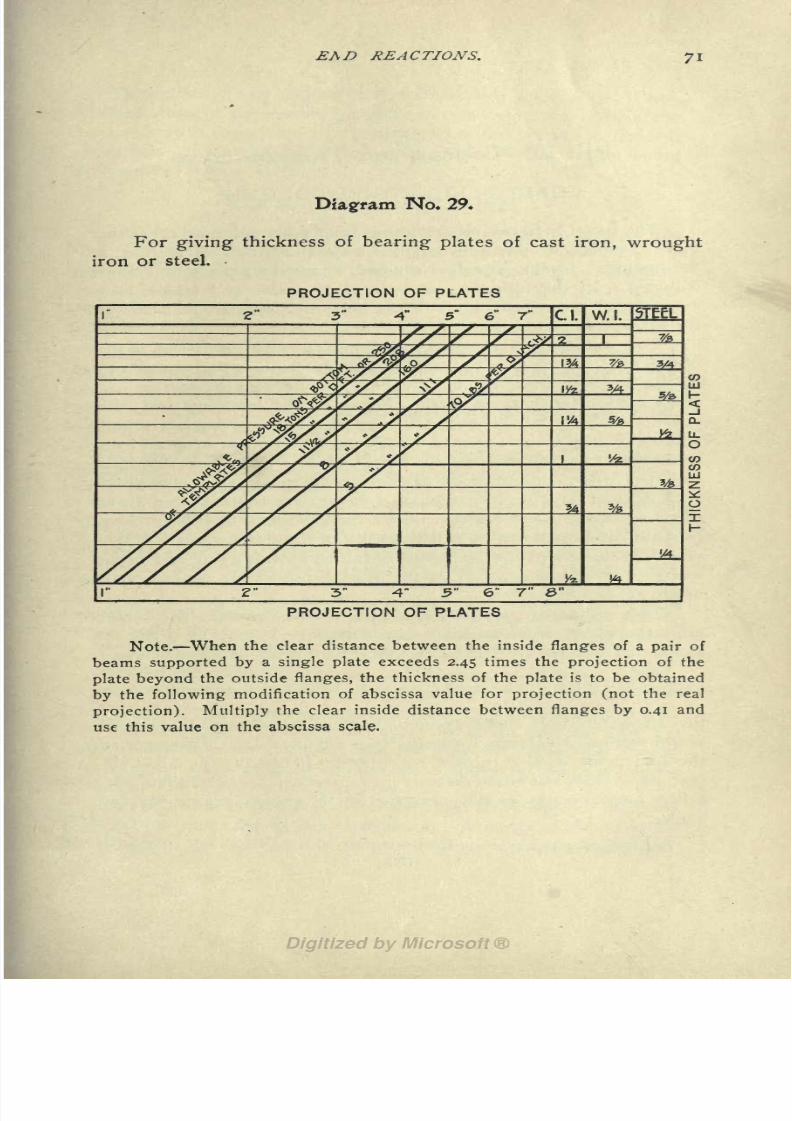
8/8/2019 Structural Design 00 Scot u of t
http://slidepdf.com/reader/full/structural-design-00-scot-u-of-t 84/177
EAf) REACTIONS.
Diagram No. 29.
For giving thickness of bearing plates of cast iron, wrought
iron or steel.
PROJECTION OF PLATES
5" 6" 7" C 1
7F7
77o 2ft 2&WS
7-x%>
2" 3" 4" 5" 6" 7
PROJECTION OF PLATES
Note. When the clear distance between the inside flanges of a pair of
beams supported by a single plate exceeds 2.45 times the projection of the
plate beyond the outside flanges, the thickness of the plate is to be obtained
by the following modification of abscissa value for projection (not the real
projection). Multiply the clear inside distance between flanges by 0.41 and
use this value on the abscissa scale.

8/8/2019 Structural Design 00 Scot u of t
http://slidepdf.com/reader/full/structural-design-00-scot-u-of-t 85/177
Part HI. Columns and Truss Members.
CHAPTER VIL STEEL COLUMNS.
The usual methods of designing built steel columns are either
quite complex or else they apply to specific forms of section, as
for instance, to the so-called zee-bar, channel or plate and angle
columns. In the following system of diagrams and tables, how-
ever, the form and make up of the section is treated as a subject
for secondary rather than primary consideration.
The radius of gyration is an important factor in the designof columns. Numerically the radius of gyration is the square root
of the quotient obtained by dividing the moment of inertia of a
cross section by the area of the section. This mathematical com-
putation is quite laborious in the case of a built up section, mainlybecause it has to be repeated for every variation in area and dis-
tribution of the material in the cross section. It is believed, how-
ever, that such computations as these are unnecessary. DiagramsNos. 30 and 31 give the radii of gyration for the different forms
of rolled sections and for the most common forms of built sections
(see explanations later). A little study of these diagrams will con-
vince the designer that the radius obtained by this graphical means
will give results as accurate as the most conservative could wish to
use in his computations.
This radius of gyration, r, is one of two variables that deter-
mine the ratio of slenderness* of a column. The other is the un-
supported length, 1, of the column. This ratio of slenderness is
1
expressed by the quotient of,which is the factor that determines
r
the allowable unit compressive stress to be obtained from the
aforementioned column formulas (see Chapter II). However, in
the treatment of the subject of columns herewith, the allowable
unit stress does not come directly into question, because it has been
taken into account in the construction of the diagrams for safe
loads.
*See Chapter II.
(72)

8/8/2019 Structural Design 00 Scot u of t
http://slidepdf.com/reader/full/structural-design-00-scot-u-of-t 86/177
STEEL COLUMNS. 73
THREE STEPS ARE TAKEN IN THE DESIGN OF A COLUMN : First,
determination of the ratio of slenderness; second, the area of the
cross section is found; third, the make up of the section is decided.
These steps will be considered in this order, the third step being
taken up in Chapter VIII.
RATIO OF SLENDERNESS.
Three diagrams are given, two of which Nos. 30 and 31 are
used for obtaining the radius of gyration for standard sec-
tions and for built up sections respectively, and the third Diagram
No. 32 is used for obtaining the ratio of the length of the col-
umn to the radius of gyration or the so-called ratio of slenderness
of the column.
DIAGRAM NO. 30: Here abscissas represent thickness of
metal expressed as a percentage of the depth or diameter of the
section. Ordinates represent the radius of gyration in inches. The
curves represent the different arrangements of material as in-
dicated in the left hand margin.
Thus the lowest line is for an H section with neutral axis coincidentwith the web, or for a star shaped section (it will be observed that the for-
mer has a depth greater than the width of the flanges, thus corresponding
to the average I-beam properties); the next line is for a square H section
with neutral axis as before; the next is for a solid circular cross section,
etc. The uppermost curve in the diagram (that represented by a full black
line) gives the theoretical values for a section of two plates at a fixed dis-
tance back to back and gradually reduced in thickness. In practice this
section is very nearly represented by two channels or two I-beams latticed
when the diameter is taken as the distance apart of their centers of gravity.
Theoretically, this distribution of material gives the highest possible radius,
but practically, it is impossible to make use of it because the latticing does
not transmit the stresses due to eccentric loading satisfactorily.
Beside the diagram proper, supplementary abscissa scales
and ordinate scales are given. Since the abscissas represent the
thickness of metal in the section expressed as a percentage of the
diameter or depth of the section, different scales may be used to
give the thickness directly in inches for different diameters. Such
a series of scales is given in tabular form above the diagram, cov-
ering diameters from 3 ins. to 28 ins.
The principal ordinate scale on the right hand edge of the dia-
gram proper gives the radius of gyration. A series of supplemen-
tary scales to the right of this give the radius directly in inches for

8/8/2019 Structural Design 00 Scot u of t
http://slidepdf.com/reader/full/structural-design-00-scot-u-of-t 87/177
74 STRUCTURAL DESIGNERS' HANDBOOK.
any diameter of section. Seven scales are given, covering diam-
eters from 6 ins. to 18 ins. inclusive.
The abscissa scales (those in tabular form above the
diagram)show a
dotted irregular line which divides the scales into two parts. This line in-
dicates the thickness of metal which the "Code" (N. Y. C.) specifies as the
minimum for the different diameters of cast iron columns: Steel column
sections are as a general rule found to the left of the line; at any rate they
should for the sake of economy fall to the left of the line, since otherwise
the metal is needlessly thick and may be better utilized by making the sec-
tion larger and using thinner metal.
The values in this diagram are entirely independent of the
material of thecolumn, and the sections shown cover the commonforms of cast iron and wooden columns as well as the built-up sec-
tions of steel columns. It should be remembered that for all ma-
terials a similar distribution gives similar values for the radius of
gyration.
To use Diagram No. 30, after the general style of the section
of the column has been decided upon, take an abscissa representing
the thickness of metal (either as a percentage of the diameter on the
lowerscale,
or in inches on theproper
scale
abovethe
diagram)and follow the vertical up to the curve which represents the style
of section selected. The horizontal at the intersection gives the
radius of gyration on one of the ordinate scales at the right of the
diagram.
DIAGRAM NO. 31 is for the same purpose as the preceding
except that the sections are for the most common built-up steel
columns. Its construction is similar to that of the preceding dia-
gram. Curves are drawn for different sections, and the ordinates
to these curves give the radius of gyration in inches;a series of or-
dinate scales is provided at the right for different values of the diam-
eter (depth) of the section, and the radius of gyration is read off
on the appropriate scale. The left hand end of the curves denotes
the minimum thickness of metal ordinarily used in practice for any
one of the sections represented by a curve, while the right hand
end corresponds to the usual maximum thickness employed for
that type of section. The curves then show the variation of the
radius of gyration as the thickness of metal used increases from the
least to the greatest thickness ordinarily used.
NOTE: Attention is drawn to the fact that in the outline sketches for
the different sections represented by curves on this diagram, dimension ar-
rows are shown which indicate the particular dimension taken to be the

8/8/2019 Structural Design 00 Scot u of t
http://slidepdf.com/reader/full/structural-design-00-scot-u-of-t 88/177
STEEL COLUMNS. 75
"diameter." Thus, in the case of the Z-bar column, the width of the web
plate is the diameter for the neutral axis perpendicular to the web.
The use of
DiagramNo.
31
will bequite
clear from thepre-
ceding. It presupposes a selection of the type of section to be
used in the particular case, and further the ability to judge approx-
imately what relative thickness of metal will be required with that
section to carry the load.
DIAGRAM NO. 32: The ratio of slender-ness of a column is
graphically represented on this diagram. Abscissas represent
length in feet and ordinates represent the ratio of slenderness.
Curves drawn on the
diagram representvarious values of the ra-
dius of gyration in inches.
It is to be noted that while for convenience the abscissa scale shows
length in feet and the radius of gyration in inches the ratio of slenderness
or quotient of the two is given as if both were in inches.
To use the diagram for any particular problem, take an ab-
scissa equal to the length of the column in feet and follow the ver-
tical up to the curve representing the radius of gyration of the
column section selected. The horizontal at the intersection shows
on the ordinate scale the desired quotient, i. e., the ratio of the
length to the radius of gyration.
SECTION AREAS.
As previously stated the second set of diagrams give the areas
of cross sections of columns for known loads and known values for
the ratio of slenderness. These areas may conveniently be divided
into three classes;area necessary for concentric load when ends
of columns are "flat";area or areas necessary for eccentric load
when ends are flat and securely braced laterally in the direction
or directions of the eccentricity; and, area necessary when pin
ends are used. Values for these three classes of loading are given
on Diagrams Nos. 33 and 34 Diagram No. 33 which gives the
area required for concentric loading on a column with flat ends
being the principal diagram of this group, because the two latter
values are given in per cent, of the first. This is more fully ex-
plained below under the separate heads.
SECTION AREAS FOR CONCENTRIC LOADING : DiagramNo. 33 gives the safe load on medium steel columns for any ratio
of slenderness and any area of cross section. In this diagram,

8/8/2019 Structural Design 00 Scot u of t
http://slidepdf.com/reader/full/structural-design-00-scot-u-of-t 89/177
76 STRUCTURAL DESIGNERS' HANDBOOK.
abscissas represent values for any ratio of slenderness from 10 to
200; ordinates represent the area of cross section in square inches;
curves on the diagram represent different values for the safe load
capacity of the column.
Several supplementary scales appear on the diagram. At the
bottom, just above the main abscissa scale, is a scale showing
"Rate of increase of area" for any given load and length of column
with varying ratio of slenderness.
This scale will be found valuable in indicating the effect of changes in
dimensions of cross sections upon the amount of metal required in a col-
umn. Thus it shows the importance of keeping the ratio of slenderness
down as low as possible. For instance, a ratio of 170 calls for three times
as much material as a ratio of 10.
At the extreme right of the diagram is a scale of weights ;it
shows the weight of the column per lineal foot for any area of cross
section in square inches.
A further supplementary abscissa scale on the lower part of the
diagram gives the area for pin end columns in the form of percent-
age factors, based on the section area required for an equivalent
load on a column with flat ends i. e. as found on the main part of
the diagram.
SECTION AREAS FOE, CONCENTRICALLY LOADED COL-
UMNS WITH PIN ENDS: When the ends of a column are hinged
or have pin bearings it is less rigid than when the ends are flat. For
this reason lower unit stresses are allowed for pin end columns.
The "Code" (N. Y. C.) makes an equivalent provision by saying
"the
workingstress in struts of
pinconnected trusses shall not ex-
ceed 75% of the working stresses for flat ends." This gives a flat
increase of 331/3% in the area of the section for all column ratios.
The percentages given by the aforementioned supplementary
scale show values increasing as the column ratio increases. Thus,
for a column ration of 100 the percentage is 120, i. e., the pin end
column should be given one-fifth more section area than a flat-end
column with the same ratio of slenderness and with the same load;
for a column ratio of
150
the
percentage
is
nearly 155.SECTION AREAS FOR TENSION MEMBERS : The scale on
Diagram No. 33 to the left of the scale of weights, on the right
hand edge of the diagram, gives values for loads in tension for dif-
ferent areas of section (or weights per lineal foot), based on a ten-
sile strength of 16,000 Ibs. per sq. in. of net section.

8/8/2019 Structural Design 00 Scot u of t
http://slidepdf.com/reader/full/structural-design-00-scot-u-of-t 90/177
STEEL COLUMNS. 77
NOTE: This latter scale has absolutely no bearing on the use of this
diagram for the design of columns. It is intended for use in the design of
trusses where both compression and tension members occur together and
will be very useful for such work. The tables of properties of shapes in
Chapter VIII, are convenient for use with this scale as well as for use with
the diagram proper.
THE USE OF DIAGRAM NO. 33 will be evident from the pre-
ceding. Taking an abscissa equal to the ratio of slenderness of
the column, the intersection of the vertical with the curve represent-
ing the load gives the required area of section on the ordinate scale
to the left, or, the required weight per lineal foot on the ordinate
scale to the extreme right. If the column has pin ends this area (or
weight) must be multiplied by the percentage factor found on the
scale above the column ratio. The other scales are used in ac-
cordance with the foregoing descriptions.
It is generally not advisable to employ columns with a higher ratio of
slenderness than 120. The "Code" (N. Y. C.) limits important columns to
this ratio as a maximum, and the allowed stresses for columns are given
only for ratios of 120 and less. As it was considered advisable to extend the
use of Diagram No. 33 beyond this point so as to include ratios up to 200
the following method was used to supply safe values for allowable unit stress
in case of ratios between 120 and 200. Different well established column
formulas were plotted and the curve representing the unit stresses allowed
by the "Code" was extended parallel to the direction of the mean of the
other curves. The resulting curve .was used to get safe allowable unit
stresses for ratios beyond 120.
SECTION AREAS FOR ECCENTRIC LOADING: It will be re-
membered that Chapter II contains discussions on the strength of
columns under concentric and eccentric loading. The term z y
there defined as the coefficient of eccentricity when divided by the
square of the radius of gyration about the axis for which the load
is eccentric gives a percentage factor for the area necessary to take
care of the bending moment due to this eccentricity.
NOTE: A little care in the arrangement of beams and girders will of-
ten eliminate the eccentricity of loading on columns. There are, however,
many cases where it cannot be avoided. For such cases the "Code" (N. Y.
C.) provides that:
Any column eccentrically loaded shall have the stresses caused by such
eccentricity computed, and the combined stresses resulting from such eccen-
tricity at any part of the column, added to all other stresses at that part
shall in no case exceed the working stresses stated in the "Code." The ec-
centric load of a column shall be considered to be distributed equally over
the entire area of that column at the next point below at which the column
is securely braced laterally in the direction of the eccentricity.

8/8/2019 Structural Design 00 Scot u of t
http://slidepdf.com/reader/full/structural-design-00-scot-u-of-t 91/177
78 STRUCTURAL DESIGNERS HANDBOOK.
It will be apparent that these provisions have been adhered to
in the treatment of eccentric loads herewith presented.
DIAGRAM NO. 34 gives the aforementioned percentage of
area necessary to take care of eccentricity of loading. In this dia-
gram abscissas represent the radius of gyration, while ordinates
represent coefficient of eccentricity. Curves on the diagram rep-
resent the percentage of area to be added to a cross section for the
eccentricity of the loading on the column. An example will best il-
lustrate the use of Diagrams Nos. 33 and 34.
Example: A column 10 ft. long has a load of 140 tons, 15 tons of which
is located 5 ins. from each neutral axis. The column section is built up with
plates and angles in the form of an H. The assumed dimension back to back
of angles is 10 ins., and 8 ins. is the dimension the other way.
Solution: The center of gravity of the combined concentric and ec-
centric load is located 0.535 in. from both principal axis. The coefficient of
eccentricity in the direction parallel to the web is 0.535 times 5 or 2.68; in
the direction perpendicular to the web it is 0.535 times 4 or 2.14. For the
direction parallel to the web in which case the radius is 4 ins., the diagram
No. 33 gives the area of metal required for this eccentricity as 17% of what
would be required for the same load concentrically located. For the direc-
tionperpendicular
to the web in which case the radius is 2ins.,
it is
53%of that same area. The sum of these three areas which go to make up the
material of the cross section can be found in two ways from these diagrams.
First: The area required for a concentric load of 140 tons may be
found on Diagram No. 33 and the foregoing 70% (17 + 53) can then be added
to it, giving the total area of cross section.
Second: The load may be increased to what would be an equivalent
concentric load 170% of 140 or 238 tons. Evidently the area may then be
found directly on Diagram No. 33. This same diagram also gives the equiv-
alent weight per lineal foot of the section. For a concentric load of "140
tons and a ratio of slenderness of 60 this weight is 81.5 Ibs. and for a load of
238 tons, the weight of the cross section is about 139 Ibs.
According to this diagram 139 Ibs. per lin. ft. represents 41 sq. ins. of
cross section. This would require approximately 1^/4 in. thickness of metal
for the assumed dimensions of the section, thus, it would be advisable to in-
crease the dimensions until the thickness is much reduced.
The areas and weights, of structural shapes used for column
sections, are given in the next chapter.

8/8/2019 Structural Design 00 Scot u of t
http://slidepdf.com/reader/full/structural-design-00-scot-u-of-t 92/177
STEEL COLUMNS. 79
Example. The radius of gyration of a round column about 94-inch
metal is 3.25 for 10 ins. diameter.

8/8/2019 Structural Design 00 Scot u of t
http://slidepdf.com/reader/full/structural-design-00-scot-u-of-t 93/177
So STRUCTURAL DESIGNERS' HANDBOOK.
Diagram No. 3f
For giving the radius of gyration of the most common forms
of built-up column sections.
DIAMETER OF SECTION IN INCHES
6 7 8 9 10 11 12 13 14 15
...^:^=-
**" i

8/8/2019 Structural Design 00 Scot u of t
http://slidepdf.com/reader/full/structural-design-00-scot-u-of-t 94/177
STEEL COLUMNS. 81
Diagram No. 32
For giving- the ratio of slenderness of a column.
UNSUPPORTED LENGTH IN FEET
UNSUPPORTED LENGTH IN FEET
Example. A column 12 it. long with a radius of gyration of 2.6 has a
ratio of slenderness of 55.

8/8/2019 Structural Design 00 Scot u of t
http://slidepdf.com/reader/full/structural-design-00-scot-u-of-t 95/177
_ _ , Diagram No. 33
For giving the safe loads on steel columns as called for by the
New York Building Code for ratios of slenderness up to 120, andas recommended by the author for ratios between 120 and 200.
RATIO OF SLENDERNESS
Example. A column having a ratio of slenderness of 70 and a load of
54 tons requires 9.8 sq. ins. in its cross-section (or 33.3 Ibs. per lin. foot).

8/8/2019 Structural Design 00 Scot u of t
http://slidepdf.com/reader/full/structural-design-00-scot-u-of-t 96/177
STEEL COLUMNS.
Diagram No. 34
For Eccentric Loading on Columns.
This diagram gives the percentage of material necessary to
add to the cross-section of a column for any eccentricity of the
centre of gravity of its load with reference to the axial planes
through its neutral axis.
RADIUS OF GYRATION IN INCHES
\\
\\\
l> I
o
LJ
LU
\ \\\
\\V\\N \
\\\\\\ \\\\\\\\\\\\ LJ
m\\v\\\\\ \\\ \\ VN>AV \\ \ \
\\\\\\\0\\\\\ \\\\ \\ \\\\\\\ \\\\ \\
\\\\\\ \\v\\\ \\\\ \\v\\\
N\\\\
\\
\\\\ \\\ \ \
\\\\ \\\ v\\\\\\\\\\\\\\
N\\\V VO \\\\\\\\\o
RADIUS OF GYRATIONIN INCHES
Note. The material in a column-section with two principal axes of sym-
metry as in Figs. 3 to 23 may be said to perform three functions whenthe load on the column is eccentric: Part cares for the load as purely
concentric, another part cares for the load as eccentric on the axis wherethe radius of gyration is a minimum, and the remainder on the axis wherethe radius is a maximum.

8/8/2019 Structural Design 00 Scot u of t
http://slidepdf.com/reader/full/structural-design-00-scot-u-of-t 97/177
84 STRUCTURAL DESIGNERS 1 HANDBOOK.
CHAPTER VIII. TABLES.
PROPERTIES OF SINGLE AND BUILT-UP STEELSHAPES OF I-BEAMS, CHANNELS, ANGLES, TEES,
ZEES, AND FLATS FOR USE IN COLUMNS, BEAMSAND TRUSSES.
EXPLANATIONS : The tables of properties in this chapter
while intended to cover the whole range of needs in structural de-
sign, are grouped with the treatment of column design for two
reasons; first, the subject of beam design is so thoroughly covered
by independent diagram treatment, that only occasional use will be
made of beam properties; second, the subject of column design,
being impossible of independent diagram treatment because of the
complex forms of built sections, makes necessary a combination of
diagrams and tables. In the first case the use of independent dia-
grams was made possible by the simplicity of form of the standard
section, the I-beam (occasional use of channels, angles and tees
excepted), being used almost exclusively. On the other hand, col-umns have only to a very small extent become standardized as re-
gards section; practically all steel columns are built sections, i e.
are built up of elementary structural shapes, and their proportions
and sizes vary widely. This is one of the conditions that compli-
cates column design and makes it impossible of independent dia-
gram treatment.
The properties of the standard sections given in the tables are
forthe
single shapes,for a
pairof
shapes, and also,in the case of
angles and zees, for four shapes combined. In the latter case as
well as in the cases of pairs of I-beams or pairs of channels these
combined shapes are supposed to be latticed* together.
The aforementioned standard sections/}- adopted by the Amer-
ican Association of Steel Manufacturers, as represented by Car-
negie, Cambria, Jones and Laughlins and Phoenix are given in
these tables; also distinctive and well marked differences in the
Passaic andPencoyd
standards have been taken into account.
*When plates are used instead of lattice bars, the radius of gyration
should be taken from the diagrams in the preceding chapter and not from
these tables, except when special tables are appended with these values which
is the case for channel and zee-bar columns. These give correct values for
radius of gyration about both axes for cover and web plates respectively.
tSee note in Chapter III.

8/8/2019 Structural Design 00 Scot u of t
http://slidepdf.com/reader/full/structural-design-00-scot-u-of-t 98/177
TABLES. 85
NOTE: The first mentioned group of rolling mills do not in every case
roll the full list given in the tables, but differences of this kind have not been
noted.
DIMENSIONS AND WEIGHTS: The dimensions and weights
per lineal foot given for all the sections in the tables are fully ex-
plained under their respective heads. However, it should be men-
tioned that the "Practical Detailing Dimensions" given in most of
these Tables are not to be considered as arbitrary values they
represent mean values. The gage given for the I-beam is the dis-
tance between the two lines of rivets on the flanges. Thus, the dis-
tance from the center line of the web to the rivet line in the flange
on either side is equal to one-half of the gage given in the table.
The gage for channels is given from their back. Gages for a sin-
gle and double line of rivets on the legs of angles are given in the
table of angles with even legs. The first dimension in each case is
given for the gage of a single line of rivets and directly below it is
given the gages for a double line of rivets for the same leg.
As stated in the foregoing the range of application of these
tables includes : beams and columns used in buildings ;tension and
compression members used in trusses; and flanges used in plate
girders. These several uses will now be considered under their
separate heads.
BEAMS.
The more generally used beam property is the section-mo-
ment. It is given in all of the following tables for the two principle
axes of each section in foot-pounds for angles and tees and foot-
tons for all other shapes. This is the safe resisting propertyof a
beam which opposes the bending moment of the external forces
acting upon it;and the Formulas Nos. I to 14, given in Chapter I
are for the purpose of illustrating the application of this section-
moment in the design of beams or girders.
The allowable values for the web of I-beams in compression
and for the end reactions on beams have been fully described in
Chapters I and V and the use of these values will be readily un-
derstood without further explanations.WHEN IT is DESIRED TO USE PLATES ON THE TOP AND
BOTTOM FLANGES OF AN I-BEAM or a pair of I-beams, or on the
top and bottom flanges of a pair of channels, the following method
may be employed to determine the area of the plates :
From the external bending moment deduct 75% of the section-moment

8/8/2019 Structural Design 00 Scot u of t
http://slidepdf.com/reader/full/structural-design-00-scot-u-of-t 99/177
86 STRUCTURAL DESIGNERS' HANDBOOK.
of the beam or beams (given in the tables) and divide this by the product
of the depth (c. to c. of plates in feet) and 7.2. (Formula 22)
Thisquotient gives
the net area of theplates on each flange.
Diagram No. 33 may be used to find an equivalent weight per lineal
foot for such an area of metal and Table No. 25 will give the
several possible dimensions for the width and thickness of these
plates.
TRUSSES AND PLATE GIRDERS.
Thetheory
andpractice
of the
designof trusses and
plategirders (including the subject of rivet spacing) is beyond the scopeof the present book and in the following a general knowledge of
the subject, on the part of the reader, is assumed.
IN THE DESIGN OF TRUSSES, pure compression and pure
tension usually prevail in both the web and chord members. How-
ever, when loads occur on the top and bottom chords, flexure
stresses are thereby added to these direct stresses. For the design
of members in pure tension and purecompression,
no further ex-
planations will be required than have already been given ;while
for cases of combined stresses of flexure and tension or flexure and
compression the diagram for eccentric loading may be utilized in
a very simple manner:
For instance, the eccentric load P (see Fig. i) considered in the
subject of column design now becomes a transverse instead of an
axial load on the truss member, and this transverse load produces
a similar bending moment on the member. This bending moment
due to transverse loading is found by introducing a new value for z,
which is obtained as follows : Suppose, a and b are the respective
distances of the load from the two ends of the member, then, z
ab
equals for any position of the load on the truss member.
a + b
Therefore, the percentage of area of the cross section necessary
to take care of the flexure stress (either tension or compression)
can be found by the use of Diagram No. 34, after having determined
upon the value of the radius of gyration of the proposed section,
either from the following tables or from Diagram Nos. 30 or 31.
ab
The coefficient of eccentricity being y instead of z y as in
a + b

8/8/2019 Structural Design 00 Scot u of t
http://slidepdf.com/reader/full/structural-design-00-scot-u-of-t 100/177
TABLES. 87
the case of columns where y is the distance from the neutral axis
p f^_ yto the extreme fiber, as before. Thus A = \ ~ ,
HS a
-
(23).
When the load P is in the middle of the beam and both ends are
fixed, the area will be one-half that given by the above formula.
The use of the diagrams and tables for tension and compres-
sion members has already been described in the preceding chapter
on steel column design.
NOTE: Deductions for rivet holes in tension members may be made
as follows: The area of metal required for a ^-in. rivet is 0.88 sq. ins. for
every inch thickness of metal this is equivalent to a reduction of 3 Ibs. per
lin. ft. in the weight of the section. Thus, if the metal is */2 in. thick, iV Ibs.
per lin. ft. should be added to the net section. Accurate values for various
thicknesses of metal from % in. to 2 ins. are given in Table No. 25 for
l/ in. and ^ in. rivets.
PLATE GIRDERS: A general discussion of the subject of
plate girder design is beyond the scope of this book. The tables
given herewith, however, lend themselves readily to the design of
an important element of plate girders the flanges.
The area of the flange is found by the use of the following
formula when the value of the section-moment in the web is
neglected :
MbFa = 0.143 (24a)
hwhere
Fa = the net area ot the tension flange in square inches,
Mb = the external bending moment in foot-tons,
and h = the distance, in feet, between centers of gravity of flanges.
Now, as the weight per lineal foot of pairs of angles is given in
the tables in preference to the area of the sections, this formula
becomes
MbFw = 0.485 , (24)
h
where
Fw =a the weight in pounds per lineal foot of the tension flange, and the
other values same as foregoing.
It is customary to make the compression flange of a plate
girder the same as the tension flange.
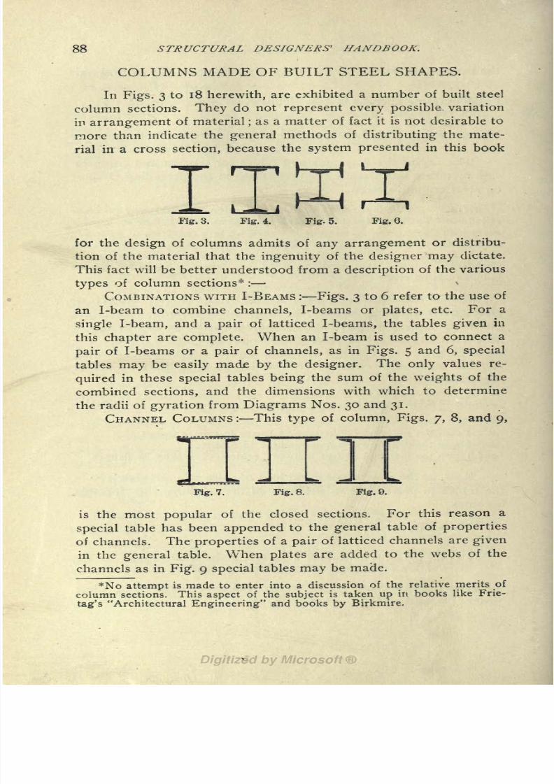
8/8/2019 Structural Design 00 Scot u of t
http://slidepdf.com/reader/full/structural-design-00-scot-u-of-t 101/177
88 STRUCTURAL DESIGNERS' HANDBOOK.
COLUMNS MADE OF BUILT STEEL SHAPES.
In Figs. 3 to 18 herewith, are exhibited a number of built steel
column sections. They do not represent every possible variation
in arrangement of material;as a matter of fact it is not desirable to
more than indicate the general methods of distributing the mate-
rial in a cross section, because the system presented in this book
Iig. 3. Fig. 4. HHFig- 5. Fig. 6.
for the design of columns admits of any arrangement or distribu-
tion of the material that the ingenuity of the designer may dictate.
This fact will be better understood from a description of the various
types of column sections* :
COMBINATIONS WITH I-BEAMS : Figs. 3 to 6 refer to the use of
an I-beam to combine channels, I-beams or plates, etc. For a
single I-beam, and a pair of latticed I-beams, the tables given in
this chapter are complete. When an I-beam is used to connect a
pair of I-beams or a pair of channels, as in Figs. 5 and 6, special
tables may be easily made by the designer. The only values re-
quired in these special tables being the sum of the weights of the
combined sections, and the dimensions with which to determine
the radii of gyration from Diagrams Nos. 30 and 31.
CHANNEL COLUMNS : This type of column, Figs. 7, 8, and 9,
Fig. 1. Fig. 8. Fig. 9.
is the most popular of the closed sections. For this reason a
special table has been appended to the general table of properties
of channels. The properties of a pair of latticed channels are given
in the general table. When plates are added to the webs of the
channels as in Fig. 9 special tables may be made.
*No attempt is made to enter into a discussion of the relative merits of
column sections. This aspect of the subject is taken up in books like Frie-
tag's "Architectural Engineering" and books by Birkmire.

8/8/2019 Structural Design 00 Scot u of t
http://slidepdf.com/reader/full/structural-design-00-scot-u-of-t 102/177
TABLES.
PLATE AND ANGLE COLUMNS: Figs. 10 to 16 illustrate in a
small way the various combinations that may be made by the use
of angles and plates. The type of column indicated by Figs. 10
and n is most popular with advocates of open sections. For this
reason a special table is also appended to the tables of properties
Fig. 10. Fig. 11. Fig. 12. Fig. 13.
Fig. 14. Fig. 15. Fig. 16.
of angles. Evidently other special tables can be made to cover
an endless variety of combinations of these two sections.
ZEE-BAR COLUMNS: Figs. 17 and 18 illustrate two of the
more common forms of this type of column. Table No. 24 thoughsmall gives quite a variety of information on these column sections.
For instance: Two methods of design are considered, one giving
weight of section for varying widths of web and the other for a
constant width of web. This latter is a favorite idea with some
designers, giving as it does, one important constant dimension for
Hig. 17. Fig. 18.
the column. Other special tables can also be made for any other
desired arrangement of material.
MISCELLANEOUS SECTIONS: The several tables on I-beams,
channels, tees, and angles may evidently be used for the application
of any single shape to strut design.

8/8/2019 Structural Design 00 Scot u of t
http://slidepdf.com/reader/full/structural-design-00-scot-u-of-t 103/177
STEEL I-BEAMS

8/8/2019 Structural Design 00 Scot u of t
http://slidepdf.com/reader/full/structural-design-00-scot-u-of-t 104/177
STEEL I-BE,AMS Continued

8/8/2019 Structural Design 00 Scot u of t
http://slidepdf.com/reader/full/structural-design-00-scot-u-of-t 105/177
STEEL I=BEAMS

8/8/2019 Structural Design 00 Scot u of t
http://slidepdf.com/reader/full/structural-design-00-scot-u-of-t 106/177
STEEL I=BE,AMS Continued

8/8/2019 Structural Design 00 Scot u of t
http://slidepdf.com/reader/full/structural-design-00-scot-u-of-t 107/177
STEEL CHANNELS
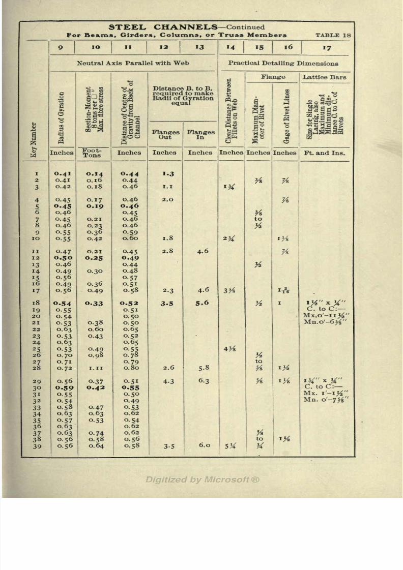
8/8/2019 Structural Design 00 Scot u of t
http://slidepdf.com/reader/full/structural-design-00-scot-u-of-t 108/177
STEEL CHANNELS Continued
For Beams. Girders, Columns, or Truss Members TABLE 18

8/8/2019 Structural Design 00 Scot u of t
http://slidepdf.com/reader/full/structural-design-00-scot-u-of-t 109/177
STEEL CHANNELS

8/8/2019 Structural Design 00 Scot u of t
http://slidepdf.com/reader/full/structural-design-00-scot-u-of-t 110/177
STEEL CHANNELS Continued

8/8/2019 Structural Design 00 Scot u of t
http://slidepdf.com/reader/full/structural-design-00-scot-u-of-t 111/177
PLATE. AND CHANNEL COLUMNS

8/8/2019 Structural Design 00 Scot u of t
http://slidepdf.com/reader/full/structural-design-00-scot-u-of-t 112/177
PLATE. AND CHANNEL COLUMNS (Continued)

8/8/2019 Structural Design 00 Scot u of t
http://slidepdf.com/reader/full/structural-design-00-scot-u-of-t 113/177

8/8/2019 Structural Design 00 Scot u of t
http://slidepdf.com/reader/full/structural-design-00-scot-u-of-t 114/177
PC
(0
23
P -
J v
O 3o -
iJ o~
MQ I2
W
I
I
coI
o>I
jo ^q
jo in
JO
uoioqsnltQ
jo i\i
jo ^q
JO
N
ro N M c>oo vo *o ro rio o o vo r>oo a> o M
N c>t^ t^ CX) lOVO VO t^OO 00
_-4
Hlg
uo
M ONCX v to ro p M CNOO O to ro pi
ro ro rj- iovo t^OO rh * iO\O t^OO O
O PI * t^
ro O *> to P< O>vdPI ro ro * 10 iOVO
O PI <* t~
OTj-
1C
ru
8
jo snip^a: iM
jo eni
jo ^q
qOB9 JO
OtoQtoQtoO
N ^IO IO
9
(101)
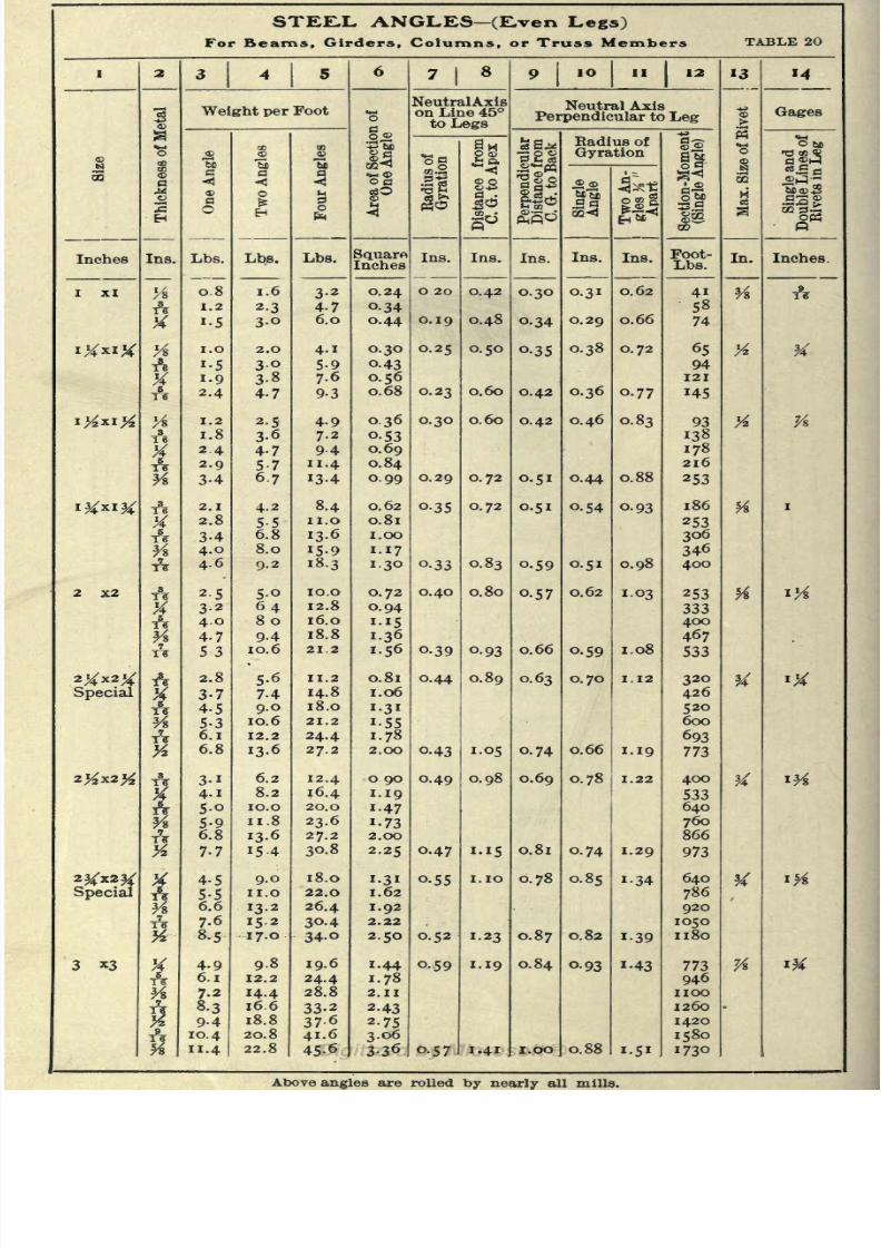
8/8/2019 Structural Design 00 Scot u of t
http://slidepdf.com/reader/full/structural-design-00-scot-u-of-t 115/177
STEJLL ANGLES (E,ven Legs)
For Beams, Girders, Columns, or Truss Members TABLE 20

8/8/2019 Structural Design 00 Scot u of t
http://slidepdf.com/reader/full/structural-design-00-scot-u-of-t 116/177
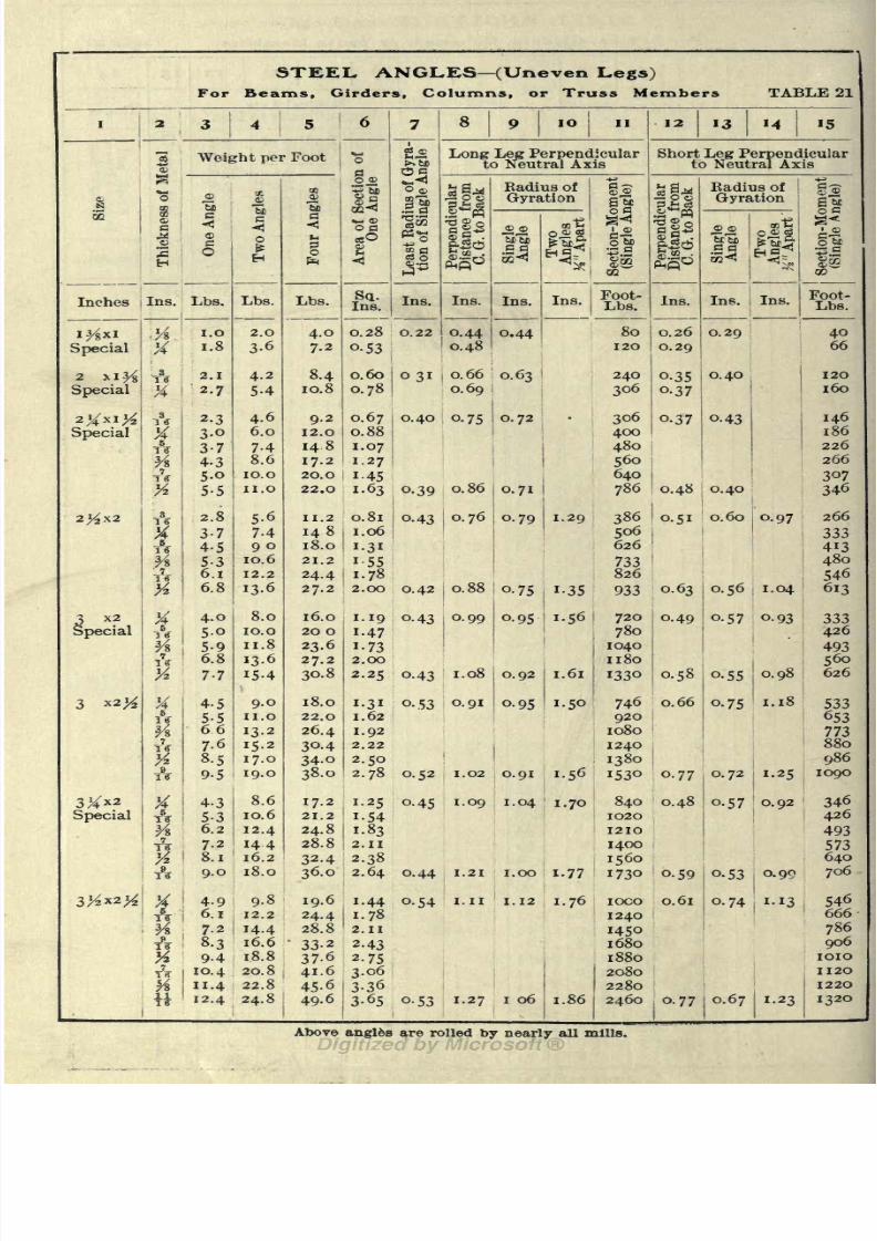
8/8/2019 Structural Design 00 Scot u of t
http://slidepdf.com/reader/full/structural-design-00-scot-u-of-t 117/177
STEEL ANGLES (Uneven Legs)
For Beams. Girders, Columns, or Truss Members TABLE 21

8/8/2019 Structural Design 00 Scot u of t
http://slidepdf.com/reader/full/structural-design-00-scot-u-of-t 118/177
STEEL ANGLES (Uneven Legs) Continued

8/8/2019 Structural Design 00 Scot u of t
http://slidepdf.com/reader/full/structural-design-00-scot-u-of-t 119/177
STEEL ANGLES (Uneven Legs) Continued

8/8/2019 Structural Design 00 Scot u of t
http://slidepdf.com/reader/full/structural-design-00-scot-u-of-t 120/177
PLATE
AND
ANGLE
COLUMNS.
(Supplement
to
Table
21.)
TABLE
22
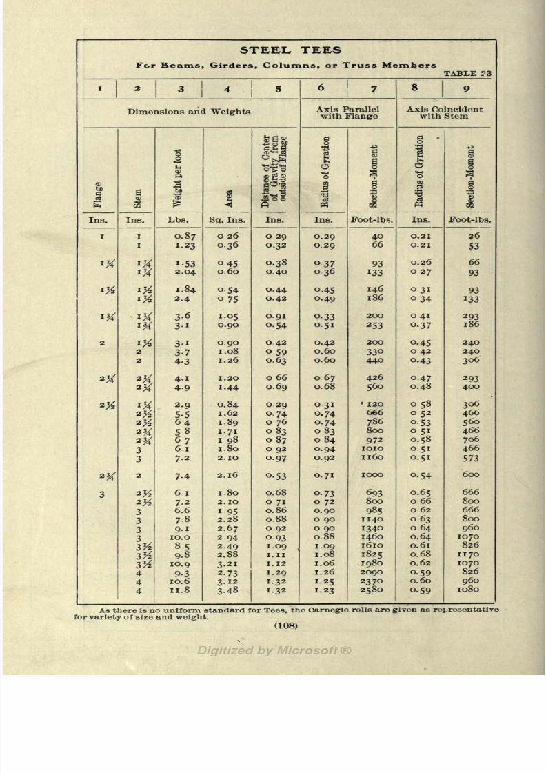
8/8/2019 Structural Design 00 Scot u of t
http://slidepdf.com/reader/full/structural-design-00-scot-u-of-t 121/177
STEEL TEES

8/8/2019 Structural Design 00 Scot u of t
http://slidepdf.com/reader/full/structural-design-00-scot-u-of-t 122/177
STEEL TEES Continued

8/8/2019 Structural Design 00 Scot u of t
http://slidepdf.com/reader/full/structural-design-00-scot-u-of-t 123/177
STE.EL ZE.E-BARS
For Beams. Girders, Columns, or Truss Members TABLE 24

8/8/2019 Structural Design 00 Scot u of t
http://slidepdf.com/reader/full/structural-design-00-scot-u-of-t 124/177
jrffciIP125
fillIjyf
oo ON ^-vo ON M co mO M M' M' M M M' N N
t<* ON M T*-
N N CO co
VO 00 Oco co *$
ro m r- o\ M co mooin m m m vo" vo" vo" vo
vo 00 0\ OO O O M
N co T*- m t>.oO ON O M co r*-VO
co co co cot^00_
ON M
CO CO CO TJ-
WEIGHTS
OF
FLAT
ROLLED
STE,EL
Pounds
Per
Lineal
Foot
cb
VOO
N VO ON OM ON r^VO
4od
N VO 00 Ot^ m co NON cot^ M'
i invo
CO m Q QCO M Q 00
co mOO OVO * N M
mOO N VO O ^OO M m O\ c*5 t^ O ^OO NVOVOt^.t OOOOOOO* OiONO MMMN
VO O TJ- > M Aod ci
Tj-mmm VOOOt^
M- ti-i r-oio ln m<o vo vo ^00 0?00 ON ON 'ON O O^O
m * * N Ot> ON M co in
N' m O"N N mM M M M N
OOOVOVOt^oo O N
O l^'O VO in N N HH
N m m f- ON IH coin-i Ooo O
i-i rfr^Oin m mvo
M t^mroOt^ VOVOVOVO
MMMMmmmmO covo' O\m m m m
M oo * Ooo m co M
covo' d\ NMMMM
VO N ONVO M 00 T- O00 VO CO M ONVO "* M4^0 co
VOON
VOfOONinO oomm M
ON M ^h r>*
vot^t-^t^
t^cooo 3-
N m t^. OMMMM
m O m OM t^ M oo
co mod O
in O m Qco ON T^- Oco mod M"
OmOMVON
m O " OON m O VO
vo oo Mvo vo t^
O Mt^. O
OOOm O N vo O
O* N m t^.
^00 M VOt^ O * t^
oN N ^vo"
00 N VO OO Tt *^ M
O\ M covo"
MOOOm
N moo Ovo t^oo O M N com
ON M comM M N M
M moo Ovo t>-oo O
rj- moo Ovo r-^oo O
moo Ot^oo
MMcoro mmmmO N
O N
00 ON M CO
OO O N ^fM M M N
*vo oo ON M M CO
vo' od o" NN N CO CO
M ^VO t>
CO fO CO CO
CO COCO-*
OMT*-m 00 ON M corj- * mmmm m m
mm invo
od d M' ^~vnvo vo vo
vo 00 O O
oX M' com
M CO-^VOMIM O ON
ri ON M' N
N
M' rf\o" 00CO CO CO CO
s'ssaO N rt- mTh Tt T^- Tj-
O 00 ON Orj- co N M
Tt-^rf-OOVOrl-
^^.svo" oo' d\ M'
oo o O O^ CO M ON
co m t^.od
RM N Nin co M
O N T?-VO'
ON t^ in co
t-i. O\ M CO
VO VO VO 00
mvo' oo" O
00 O Q Oco N O oo
M" ^-vo" fr*
oo
oo O M co
M oo m MM" com t~-
N M N N
ooooONVO co O
oooot^ ^ M oo
inco ONmMtvo' t-^. ON M' N'
coONmMTJ- m t>- d\
MNMOt^coONin M VO M OO
cT'S S)co
H- CO CO N N M QT|-
O VO N 00 rj- OM co TJ- vo" *> ON M* * Tj- ^ rj- -^ if
in rh co M oON * ON Tj- ON
m r-^od d M
ONOO vo in co N M O T^ co N OMVOMVO
mvo oo ONN M N N
t^OO O Mco co -d- Tf
ON M VO Ovo" od oS M*
rtOO M mN* co mvo"
N VO
N M N N
OCOI^M
O oo in coM
covqo\
m vo' t-^oo' O M' M' rt- m vo* t^. ON O M* M' rf mM MMMM MMMM NMNN
t^q covq
vo* od o\ dN N N co
M co m vo oo ON4
t^ rj-MOOinvo oo O M co
rf m t>.od oS
invo oo
d M' M'
O\vo coOMcomt^mvo' t-^oo"
rJ-MOts
ON O M" N"
N CO co co
ONVO co OooONri-
mvo t>-odinvq vq
t^
d\ d M" M"
00 0^" ON 8co ^ m i-"-
CO ON inMMM00 0\ O M
voO co co ^T in
M' co TJ- mi^coONm Mt^-d-nmvq vq
t^ oo oo ON qvo' r>-oo' ON O M' M' ^-

8/8/2019 Structural Design 00 Scot u of t
http://slidepdf.com/reader/full/structural-design-00-scot-u-of-t 125/177
112 STRUCTURAL DESIGNERS^ HANDBOOK.
CHAPTER IX. CAST IRON COLUMNS.
Cast iron columns are rarely used for very high skeleton con-struction. They should never be so used when there is great
eccentricity in the loading.* They are widely used for buildings of
medium height, where outer bearing walls are provided or where
a sufficient distribution of substantial inclosure and curtain walls
exists to brace the building adequately against lateral forces.
Cast iron columns do not lend themselves readily to the at-
tachment of wind bracing, and because of the loose connections of
the beams they should seldom be used where wind bracing is neces-
sary.
Different forms of cross section are used for cast iron columns.
The square section is used a great deal where the column is to be
built into a wall;the round section is generally used for columns
standing free in a room;and the other form of section the H shape
is very popular for either wall or free columns the latter only
when it is to be encased in brick or plaster work. This section
has the advantage of being open for inspection andit is
easy tocore. A special section of the same class designed by the author
is shown in Fig. 20. It is suitable for large size columns, in
fact, it is simply a practical extension of the use of the H section
beyond the limits of the simple form. For small posts or struts
such as, stair posts and the like, the star section (Fig. 23) is some-
times used.
IN THE DESIGN OF A CAST IRON COLUMN three steps are
taken:
first,, the ratio of slendernessis fixed within certain limits
;
second, the area of the section is found; and third the section is
designed.
The first step has already been described in Chapter VII and
the Diagrams Nos. 30 and 32 (as well as Diagram No. 34) found
in that chapter will be used in conjunction with the diagrams in
this chapter.
The second and third steps will be fully explained in the de-
scriptions of DiagramsNos.
35and
36.
Diagram No. 35 is based on the provisions for allowable
stresses contained in the "Code" (N. Y. C.). Diagram No. 36
*Small eccentricities of loading are sometimes allowed by increasing the
area of the section enough to take care of the bending stress due to the ec
centricit>.

8/8/2019 Structural Design 00 Scot u of t
http://slidepdf.com/reader/full/structural-design-00-scot-u-of-t 126/177
CAST fRON COLUMNS. 113
embodies what the author considers to be more conservative
values* for use in general practice. For a column ratio of 10
the allowed stress is just the same as for the preceding diagram,
but the reduction of stress with increasing ratio of slenderness is
much greater than that provided by the "Code."
DIAGRAMS NOS. 35 AND 36 : The construction of these dia-
grams is similar to that of No. 33 for steel columns. Abscissas
represent column ratios, ordinates represent areas and the loads
are represented by the curves on the diagram. A supplementary
ordinate scale at the right of these diagrams also gives the weight
per lineal foot for any area of cross section. This value is given
in the tables following these diagrams in preference to the area of
the section because of its double value for both design and esti-
mates.
An example will best illustrate the application of diagrams to
the design of cast iron columns loaded with concentric and eccen-
tric loads.
Example: A column 10 ft. long has a load of 75 tons, 8 tons of which
is located 6 in. from the neutral axis
perpendicularto the web. The column
section is the H as shown in Fig. 19 and is assumed to be 10 ins. square.
Solution: The center of gravity of the combined concentric and ec-
centric load is 0.64 in. from the neutral axis perpendicular to the web. The
coefficient of eccentricity is 5 times 0.64 or 3.2. The radius of gyration is
4 ins. about the axis perpendicular to the web, in which case the area re-
quired for this eccentricity is 20% of what would be required for the same
load concentrically located, thus for the above load eccentrically located an
equivalent concentric load is 120% of 75 or 90 tons.
OnDiagram
No.36
the arearequired
for a load of9.0
tons on
a column with a ratio of slenderness of 50 is 3.15 sq. ins., therefore,
for a column load of 90 tons the area would be 31.5 sq. ins. This
same diagram gives the weight per lineal foot of column section
for the above load as 98.5 pounds.
According to Table No. 26 a 10 x 10 column \\ in. metal is the
nearest to this requirement.
The reader is referred to a valuable discussion on the strength of cast
iron columns in "Kent's Mechanical Engineer's Pocket Book," pp. 250-252.

8/8/2019 Structural Design 00 Scot u of t
http://slidepdf.com/reader/full/structural-design-00-scot-u-of-t 127/177
DESIGNERS; HANDBOOK.
Diagram No. 35
For givingthe safe loads on cast-iron columns as
specified
by the New York Building Code.
10 40 70
15
LU
O
OLJJ
CO
fe
\0
&
3
\O
10
6-Z
]0 40 70
RATIO OF SLENDERNESS

8/8/2019 Structural Design 00 Scot u of t
http://slidepdf.com/reader/full/structural-design-00-scot-u-of-t 128/177
Diagram No* 36
For giving the safe loads on cast-iron columns as recommended
by the author.
20
10 20 AO 50 60-701100
10 20 SO 60 70
RATIO OF SLENDERNESS
(115)
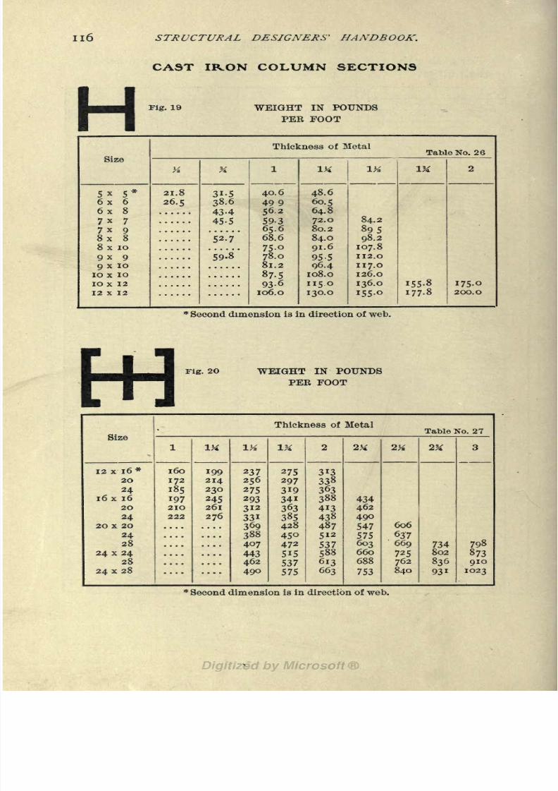
8/8/2019 Structural Design 00 Scot u of t
http://slidepdf.com/reader/full/structural-design-00-scot-u-of-t 129/177
STRUCTURAL DESIGNERS' HANDBOOK.
CAST IKON COLUMN SECTIONS
HFig. 19 WEIGHT IN POUNDS
PER FOOT
Size
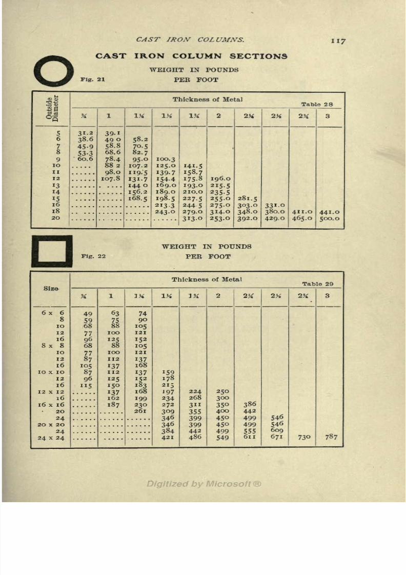
8/8/2019 Structural Design 00 Scot u of t
http://slidepdf.com/reader/full/structural-design-00-scot-u-of-t 130/177
O
CAST IRON COLUMNS.
CAST IRON COLUMN SECTIONS
117
Fig. 21
WEIGHT IN POUNDS
PER FOOT
Outside
Diameter

8/8/2019 Structural Design 00 Scot u of t
http://slidepdf.com/reader/full/structural-design-00-scot-u-of-t 131/177
STRUCTURAL DESIGNERS' HANDBOOK.
CAST IRON COLUMN SECTIONS
WEIGHT IN POUNDS
Fig. 23 PEE FOOT

8/8/2019 Structural Design 00 Scot u of t
http://slidepdf.com/reader/full/structural-design-00-scot-u-of-t 132/177
Part IV. Miscellaneous*
CHAPTER X. LOADS.
Before the framework of a building can be designed, the ex-
ternal forces which act on the structure, i. e., the loads, must be
known or assumed. In this chapter are given some average values
which
maybe used for the different items in
estimating loads,to-
gether with the principal provisions regarding loading which are
found in the "Code" (N. Y. C).
Loads are usually divided into Dead Loads, Live Loads and
Wind Loads. Sometimes wind loads are included under live
loads.
DEAD LOADS.
THE DEAD LOADS CARRIED BY FLOOR GIRDERS consist of.
the steel beams, connection angles, tie rods and other fittings ;
floor arches, nailing strips, rilling and finished flooring ; partitions,
stairs and other permanent construction; and suspended ceilings,
pipes and conduits.
THE DEAD LOADS CARRIED BY COLUMNS consist of: the
dead loads from the floor or floors supported by the column;the
column itself, including the metal and covering material;all pipes
and conduits suspended to the column;and loads from trusses or
girders carrying brick walls, vaults or other permanent loads.
THE WEIGHT OF STEEL FLOOR FRAMING may be deter-
mined approximately from the two accompanying Diagrams Nos.
37 and 38. Diagram No. 37 applies to floors intended to carry a
total load (live and dead) of about 150 Ibs. per sq. ft. DiagramNo. 38 applies to floors intended to carry a total load of about
300 Ibs. per sq. ft. In these diagrams abscissas represent span in
feet, and ordinates representweight
of steel per square foot of
floor. Two sets of lines are drawn on each diagram : the upper
set consisting of three lines is for floor beams spaced 3, 4 or 5 ft.;
the lower five lines are for floor girders, representing spacings of
10, 15,20,25 and 30 ft.
To use either of the two diagrams, take an abscissa equal to
(119)

8/8/2019 Structural Design 00 Scot u of t
http://slidepdf.com/reader/full/structural-design-00-scot-u-of-t 133/177
Diagram No* 37
For giving the weight of steel required in floors where the
loads are a minimum.
SPAN OF BEAMS IN
1O
FEET OR SPAN OF GIRDERS IN FEET.
15 ZO 25 30
vO
N
Cw.-BPfepj. Solu^
F OR
<*/
*7
7
7
/
ft
N
WElCHTCT 0/4 RM<:U
10 \5 2O 25> 30SPAN OF BEAMS IN FEET OR SPAN OF GIRDERS IN FEET
(12C)
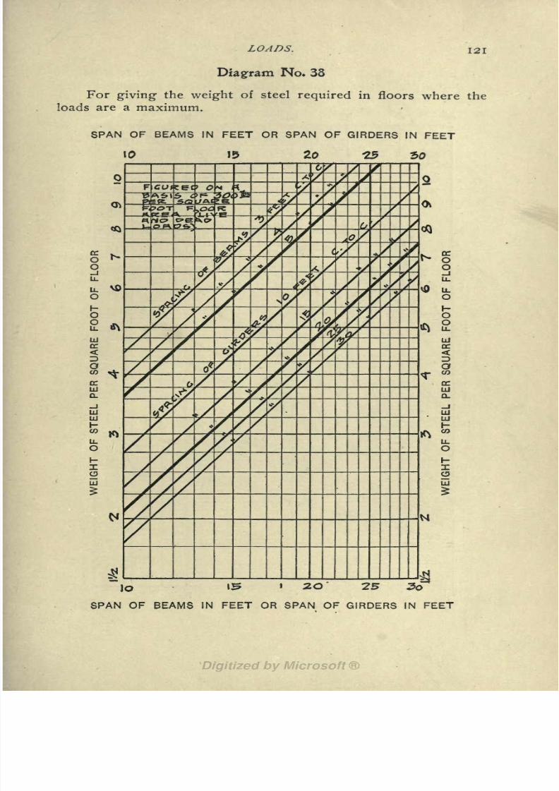
8/8/2019 Structural Design 00 Scot u of t
http://slidepdf.com/reader/full/structural-design-00-scot-u-of-t 134/177
LOADS. I2i
Diagram No* 38
For giving the weight of steel required in floors where the
loads are a maximum.
SPAN
<*>
NOu.
u. VO
15
& IV
UJ
K<D
DC
UI
a.
UJ
UJ
wLL

8/8/2019 Structural Design 00 Scot u of t
http://slidepdf.com/reader/full/structural-design-00-scot-u-of-t 135/177
122 STRUCTURAL DESIGNERS' HANDBOOK.
Diagram No. 39
For giving the weight of joists per square foot of floor.
DEPTH OF JOIST
6" a" JO" 12" 14" 16"
f
10- -15
9-
0z-l2-rl6r
7EE
5. Y.Pw.o.
-14-
9--I2-
3- -G-
^^3:^4-
5. Y.RW.O
6" S 10" 12" 14"
DEPTH OF JOIST
16"
8/8/2019 Structural Design 00 Scot u of t
http://slidepdf.com/reader/full/structural-design-00-scot-u-of-t 136/177
LOADS. 123
the span of the floor beams in feet and follow up to the diagonal
representing the assumed spacing of the beams in feet. The hori-
zontal at the intersection gives the weight of floor beams in pounds
per square foot of floor. Then take an abscissa equal to the spanof the girders and follow to the diagonal representing the spacing
the horizontal at the intersection gives the weight of the girders
per square foot of floor. The sum of the weights of the beams anJ
the girders gives the total weight of steel per square foot of floor.
At the bottom of Diagram No. 37 are two curves which represent ap-
proximately the limiting weights of connection angles per square foot of
floor for different spans of beam. Evidently these weights are too small
to affect theloading.
THE WEIGHT OF WOODEN FLOOR BEAMS may be deter-
mined approximately from Diagram No. 39 herewith. In this dia-
gram abscissas represent depth of the beam and ordinates represent
weight per square foot of floor. The diagonal lines on the diagram
represent different breadths of beam, and different spacing of
beams. The ordinates may be measured on one of three scales at
the right of the diagram : these scales give the weights per square
foot of floor respectively for white pine, spruce and yellow pine
or white oak.
FLOOR ARCHES: The weight of tile arches varies from 18
to 40 Ibs. per sq. ft. according to the depth, density of tile, thick-
ness, and distance of webs apart. About 5 IDs. per sq. ft. should
be added to the weight of floor arches for the mortar in the joints.
The weight of concrete arches varies from 18 to 40 Ibs. per sq. ft.
according to the span of the arch and to the system of construc-
tion* adopted. ;
FLOORING MATERIAL: Hardwood floors weigh about 4
Ibs. per sq. ft., for every inch in thickness, and softwood about 3
Ibs. Nailing strips weigh about 2 Ibs. per sq. ft. of floor. Tile or
terrazza floors weigh about 14 Ibs. per sq. ft. for every inch in
thickness.
Concrete filling weighs from 6 to 8 Ibs. per sq. ft. for every
inch in thickness according to composition.
Plastered ceilings weigh about 8 Ibs. per sq. ft. In case of sus-
pended ceilings, the weight of the steel work and tile or lath must
be added.
*Valuable information on the various flooring systems will be found in
Frietag's "Architectural Engineering" and Kidder's "Building Construction
and Superintendence," Part I.

8/8/2019 Structural Design 00 Scot u of t
http://slidepdf.com/reader/full/structural-design-00-scot-u-of-t 137/177
124 STRUCTURAL DESIGNERS' HANDBOOK.
PARTITIONS : Tile plastered on both sides weighs from 24
to 40 Ibs. per sq. ft. of wall surface. Expanded metal weighs from
18 to 22 Ibs. per sq. ft.
BRICK WALLS : The weight of walls will be found on Dia-
gram No. 40 in Chapter XII.
LIVE LOADS.
Live or variable loads consist of all loads other than dead
loads. The "Code" (N. Y. C.) provides that :
"Every floor shall be of sufficient strength to bear safely the weight to
beimposed
thereon in addition to the
weightof the materials of which the
floor is composed. Thus:
Floor Loads per sq. ft.
Dwelling house 60 Ibs.
Apartment house 60"
Tenement house 60'
Hotel or lodging house 60"
Office buildings:
Above ist floor 75"
ist floor150
"
School or place of instruction 75"
Stable or carriage house 75"
Place of public assembly 90"
Ordinary stores, light manufacturing and light storage. .120"
Store where heavy materials are kept, warehouse or fac-
tory 150"
Roofs pitch less than 20 50"
pitch more than 20 30"
(load on a horizontal plane.)
Sidewalks'between the curb and area lines 300 "
"For the purpose of determining the carrying capacity of columns in
dwellings, office buildings, stores, stables and public buildings when over
five stories in height, a reduction of the live loads shall be permissible as
follows:
"For the roof and top floor the full live loads shall be used; for each
succeeding lower floor it shall be permissible to reduce the live load by 5%until 50% of the live loads fixed by this section is reached, when such re-
duced loads shall be used for all remaining floors."
The strength of factory floors intended to carry running ma-
chinery should be increased about 50% above the preceding pro-
visions.
Regarding the reduction of live loads on columns, as speci-
fied in the above quotation, it may be remarked that this does not

8/8/2019 Structural Design 00 Scot u of t
http://slidepdf.com/reader/full/structural-design-00-scot-u-of-t 138/177
LOADS. 12$
take into account the area of floor tributary to the column as af-
fecting the allowable percentage of reduction a rational provision
should allow for this.
LIVE LOADS ON FOOTINGS : According to the "Code" (N.
Y. C.) the loads exerting pressure under the footings of founda-
tions in buildings more than three stories in height are to be com-
puted as follows :
"For warehouses and factories they are to be the full dead and the full
live load. In stores and buildings for light manufacturing purposes they arc
to be the full dead load and 75% of the live load. In churches, school houses
and places of public amusement, they are to be the full dead load and 75%
of the live load. In office buildings, hotels, dwellings, apartment houses,
tenement houses, lodging houses and stables, they are to be the full dead
load and 60% of the live load. Footings shall be so designed that the loads
will be as nearly uniform as possible and not in excess of the safe bearing
capacity of the soil."
WIND PRESSURE ON BUILDINGS : The wind pressure al-
lowed for on buildings is very much a matter of guess work. The
provisions of the "Code" (N. Y. C.) however, are recognized as rep-
resentingsafe limits. These
providethat:
"All structures exposed to wind shall be designed to resist a horizontal
wind pressure of 30 Ibs. for every sq. ft. of surface thus exposed, from the
ground to the top of same including roof, in any direction. In no case shall
the over-turning moment due to wind pressure exceed 75% of the moment
of stability of the structure. In all structures exposed to wind, if the resist-
ing moments of the ordinary materials of construction, such as masonry,
partitions, floors and connections, are not sufficient to resist the moment of
distortion due to wind pressure, taken in any direction on any part of the
structure, additional bracing shall be introduced sufficient to make up the
difference in moments. In calculations for wind bracing, the working
stresses set forth in this code may be increased by 50%. In buildings under
100 ft. in height, provided the height does not exceed four times the average
width of the base, the wind pressure may be disregarded."
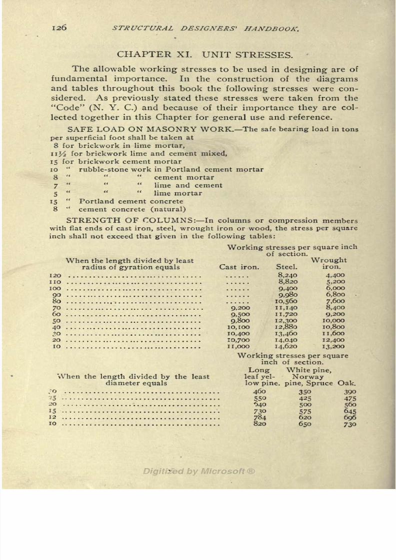
8/8/2019 Structural Design 00 Scot u of t
http://slidepdf.com/reader/full/structural-design-00-scot-u-of-t 139/177
126 STRUCTURAL DESIGNERS 1 HANDBOOK.
CHAPTER XI. UNIT STRESSES.
The allowable working stresses to be used in designing are of
fundamental importance. In the construction of the diagrams
and tables throughout this book the following stresses were con-
sidered. As previously stated these stresses were taken from the
"Code" (N. Y. C.) and because of their importance they are col-
lected together in this Chapter for general use and reference.
SAFE LOAD ON MASONRY WORK. The safe bearing load in tons
per superficial foot shall be taken at
8 for brickwork in lime mortar,
nl
/ for brickwork lime and cement mixed,
15 for brickwork cement mortar
10 rubble-stone work in Portland cement mortar
8'
cement mortar
7" "
lime and cement
5" "
lime mortar
15 Portland cement concrete
8''
cement concrete (natural)
STRENGTH OF COLUMNS: In columns or compression members
with fiat ends of cast iron, steel, wrought iron or wood, the stress per squareinch shall not exceed that given in the following tables:
Working stresses per square inch
of section.
WroughtCast iron. Steel.
120 8,240
no 8,820
100 9,400
90 9,980
80 10,560
70 9,200 11,140
60 9,500 11,720
50 9,800 12,300
40 10,100 12,880
30 10,400 13,460
20 10,700 14,040
10 11,000 14,620
Working stresses per squareinch of section.
Long White pine,
leaf yel- Norway
low pine, pine, Spruce Oak.^ 460 350 390
-5 550 425 47520 640 5OO 500
15 730 575 64512 784 620 69610 820 650 730
When the length divided by least
radius of gyration equals iron.
4,400
5,200
6,000
6,800
7,600
8,400
9,200
10,000
10,800
1 1,600
12,400
13,200
When the length divided by the least
diameter equals

8/8/2019 Structural Design 00 Scot u of t
http://slidepdf.com/reader/full/structural-design-00-scot-u-of-t 140/177
UNIT STRESSES. 127
And in like proportion for intermediate ratios. Five-eighths the values
given for white pine shall apply to chestnut and hemlock posts. For locust
posts use il/ the value given for white pine.
Columns and compression members shall not be used having an unsup-
ported length of greater ratios than given in the tables.
WORKING STRESSES: The safe carrying capacity of the various
materials of construction (except in the case of columns) shall be deter-
mined by the following working stresses in pounds per square inch of sec-
tion area:
COMPRESSION (DIRECT).
With Across
Rolled steel 16,000 grain, grain.*
Cast steel 16,000 Oak 900 500
Wrought iron 12,000 Yellow pine 1,000 350
Cast iron (in short blocks) . 16,000 White pine 800 200
Steel pins and rivets (bear- Spruce 800 200
ing) 20,000 Locust 1,200
Wrought iron pins and rivets Hemlock 500 150
(bearing)
'
15,000 Chestnut 500 25
Concrete (Portland) cement, I; sand, 2; stone, 4 230
Concrete (Portland; cement, i; sand, 2; stone, 5 208
Concrete, Rosendale, or equal, cement, i; sand, 2; stone, 4.. 125
Concrete, Rosendale, or equal, cement, i; sand, 2; stone, 5.. in
Rubble stonework in Portland cement mortar 140
Rubble stonework in Rosendale cement mortar in
Rubble stonework in lime and cement mortar 97
Rubble stonework in lime mortar 7
Brickwork in Portland cement mortar; cement, i; sand, 3. ... 250
Brickworkin
Rosendale,or
equal,cement
mortar; cement, i;
sand, 3 208
Brickwork in lime and cement mortar; cement, i; lime, i;
sand, 6 160
Brickwork in lime mortar; lime, i; sand, 4 in
Granites (according to test) 1,000 to 2,400
Greenwich stone 1,200
Gneiss (New York City) 1,300
Limestones (according to test) 700 to 2,300
Marbles (according to test) 600 to 1,200
Sandstones (according to test) 400 to 1,600
Bluestone, North River . 2,000
Brick (Haverstraw, flatwise) 300
Slate 1,000
*These values for compression across the grain have been revised bythe author.

8/8/2019 Structural Design 00 Scot u of t
http://slidepdf.com/reader/full/structural-design-00-scot-u-of-t 141/177
128 STRUCTURAL DESIGNERS' HANDBOOK.
TENSION (DIRECT).
Rolled steel 16,000 White pine 800Cast steel 16,000 Spruce 800
Wroughtiron 12,000 Oak i,oou
Cast iron 3,000 Hemlock 600
Yellow pine 1,200
SHEAR.
Steel web plates 9,000 With AcrossSteel shop rivets and pins.. 10,000 fiber. fiber.
Steel field rivets 8,000 Yellow pine 70 500Steel field bolts 7,000 White pine 40 250
Wrought iron web plates. . . 6,000 Spruce'
.50 320
Wrought iron shop rivets Oak .- . . . 100 600
and pins 7,5oo Locust 100 720
Wrought iron field rivets.. 6,000 Hemlock 40 275
Wrought iron field bolts... 5,500 Chestnut 150Cast iron 3,ooo
SAFE EXTREME FIBER STRESS (BENDING).
Rolled steel beams 16,000 Granite 180
Rolled steel pins, rivets and Greenwich .stone 150
bolts 20,000 Gneiss (New York City) 150
Riveted steel beams (net Limestone 150
flange section) 14,000Slate
400Rolled wrought-iron beams. 12,000 Marble 120
Rolled wrought-iron pins, Sandstone 100
rivets and bolts 15,000 Blue stone, North River 300
Riveted wrought-iron beams
(net flange section) ....... 12,000 Concrete (Portland) cement,
Cast-iron, compression side. 16,000 i; sand, 2; stone, 4 30
Cast-iron, tension side 3,ooo Concrete (Portland) cement,Yellow pine 1,200 i; sand, 2; stone, 5 20
White pine 800 Concrete (Rosendale, or equal)
Spruce 800 cement, i; sand, 2; stone, 4.. 16
Oak 1,000 Concrete (Rosendale, or equal)Locust :
1.200 cement,i
;
sand, 2; stone, 5..10
Hemlock 600 Brick (common) 50Chestnut 800 Brickwork (in cement) 30
BEARING CAPACITY OF SOIL. Where no test of the sustaining
power of the soil is made, different soils, excluding mud, at the bottom of
footings shall be deemed to safely sustain the following loads in tons per
superficial foot, namely:
Soft clay i.
Ordinary clay and sand together, in layers, wet and springy 2.
Loam, day or fine sand, firm and dry 3.
Very firm, coarse sand, stiff gravel or hard clay 4.
"When a doubt arises as to the safe sustaining power of earth uponwhich a building is to be erected, the Department of Buildings may order
borings to be made, or direct the sustaining power of the soil to be tested
by and at the expense of the owner of the proposed building."

8/8/2019 Structural Design 00 Scot u of t
http://slidepdf.com/reader/full/structural-design-00-scot-u-of-t 142/177
BRICK WALLS. I2Q
CHAPTER XII. BRICK WALLS.
The walls of a building are an important part of the loads in
the case of skeleton construction. In the case of building where
the walls are the principal supporting element the strength, thick-
ness, etc., of the walls are essential items in their design. In manycities the building laws prescribe the thickness for the various con-
ditions in the construction of walls. An especially full set of provi-
sions of this nature is contained in the "Code" (N. Y. C.) and they
are taken as a basis for this chapter. These provisions divide the
walls of buildings into three classes : walls for dwelling houses,
walls for warehouses and inclosure walls for skeleton structures.
WALLS FOR DWELLING HOUSES. This class includes the fol-
lowing buildings:
Apartment Houses, Hotels,
Asylums, Laboratories,
Club Houses, Lodging Houses,
Convents, Parish Buildings,
Dormitories, Schools,
Dwellings, Studios,
Hospitals, Tenements.
WALLS FOR WAREHOUSES. This class includes the following
buildings:
Armories, Observatories,
Breweries, Office Buildings,
Churches, Police Stations,
Cooperage Shops, Printing Houses,Court Houses, Public Assembly Buildings,
Factories, Pumping Stations,
Foundries, Railroad Buildings,
Jails, Slaughter Houses,
Libraries, Stables,Light and Power Houses, Stores,
Machine Shops, Theatres,
Markets, Warehouses,
Mills, Wheelwright Shops.
Museums,
INCLOSURE WALLS FOR SKELETON STRUCTURES. These
are walls of brick built in between iron or steel columns, and supported
wholly or in part on iron or steel girders.
THICKNESS AND WEIGHT OF WALLS.The provisions of the "Code" for thicknesses of these three
classes of walls have been embodied in a single diagram.
DIAGRAM NO. 40 (GIVING THICKNESS AND WEIGHT OF
WALLS) : In each of the foregoing classes of walls the thickness

8/8/2019 Structural Design 00 Scot u of t
http://slidepdf.com/reader/full/structural-design-00-scot-u-of-t 143/177
1
130 STRUCTURAL DESIGNERS' HANDBOOK.
varies with the height above the curb level. These variations are
represented in five sections on this diagram. In each section the
full unshaded outline represents "warehouse walls," the dotted line
represents "dwelling house walls, and the full shaded portion repre-
sents "inclosure walls for skeleton structures." The thicknesses
for each case are indicated by vertical lines, each space of which
represents a thickness equal to one half the length of a brick or
about 4 ins. On three of these sections is given the weight of wall
per lineal foot for the different vertical heights at which the figures
for the weights are placed. These weights apply to "warehouse
walls." A supplementary scale at the right of the diagram gives the
weight per lineal foot of skeleton inclosure walls for different
heights below the top. A farther ordinate scale, at the extreme
right, gives the number of bricks in such skeleton walls, per lineal
foot of wall.
Three supplementary scales at the left of the diagram will be
found useful. They show :
(1) Number of stories, at different levels, if stories are 10 ft.
from floor to floor.
(2) The same if stories are I2| ft. from floor to floor.
(3) The floor area gained, per lineal foot of wall, by using
skeleton walls instead of warehouse walls;this latter is for the ac-
cumulated gain for all the floors the floors are assumed to be
I2j ft. apart vertically.
CONDITIONS THAT WILL MODIFY THE FOREGOING PRO-
VISIONS. "If there is a clear span of over 25 ft. between the bearing
walls* of warehouses (26 ft. for dwelling houses), such walls shall be 4 ins.
more in thickness than in this section specified, for every i2 l/ ft. or fraction
thereof, that said walls are more than 25 ft. apart (26 ft. for dwellings), or
shall have, instead of the increased thickness, piers or buttresses."
"All buildings, not excepting dwellings, that are over 105 ft. in depth,
without a cross wall or proper piers or buttresses, shall have the side or
bearing walls increased in thickness 4 ins. more than is specified in the
respective sections of this code for the thickness of walls, for every 105
ft., or part thereof, that the said buildings are over 105 ft. in depth."
"If any horizontal section through any part of any bearing wall in any
building shows more than 30% area of flues and openings, the said wall
shall be increased 4 ins. in thickness for every 15% or fraction thereof, of
flue or opening area in excess of 30%."
"Non-bearing walls may be 4 ins. less in thickness, provided none are
less than 12 ins., for warehouses and dwellings."
*Bearing walls are those walls on which beams, girders or trusses rest.

8/8/2019 Structural Design 00 Scot u of t
http://slidepdf.com/reader/full/structural-design-00-scot-u-of-t 144/177
BRICK WALLS. 131
FOUNDATION WALLS.
"When either bearing or skeleton walls are supported, the foundation
walls, if built of rubble-stone or Portland cement concrete, shall be at
least 8 ins. thicker than the wall next above them, to a depth of 12 ft. below
the curb level; and for every additional 10 ft., or part thereof, deeper, they
shall be increased 4 ins. in thickness. If built of brick, they shall be at least
4 ins. thicker than the wall next above them to a depth of 12 ft. below the
curb level; and for every additional 10 ft. or part thereof, deeper, they
shall be increased 4 ins. in thickness. The footing or base course shall be
of stone or of concrete, or both, or of concrete and stepped-up brickwork,
of sufficient thickness and area to safely bear the weight to be imposed
thereon."
"The thickness of a
RETAINING WALLat its
baseshall
bein
nocase less than one-fourth of its height."
BRICK WALLS FOR SKELETON CONSTRUCTION.
"Where columns are used to support iron or steel girders carrying in-
closure walls, the said columns shall on their exposed outer and inner sur-
faces be constructed to resist fire by having a casing of brickwork not less
than 8 ins. in thickness on the outer surfaces, nor less than 4 ins. on the
inner surfaces, and all bonded into the brickwork of the inclosure walls.
"The exposed sides of the iron or steel girders shall be similarly cov-
ered in with brickwork not less than 4 ins. in thickness on the outer sur-
faces and tied and bonded, but the extreme outer edge of the flanges of
beams, or plates, or angles connected to the beams, may project to within
2 ins. of the outside surfaces of the brick casing.
"The inside surface of girders may be similarly covered with brick-
work, or if projecting inside of the wall, they shall be protected by terra
cotta, concrete or other fireproof material."
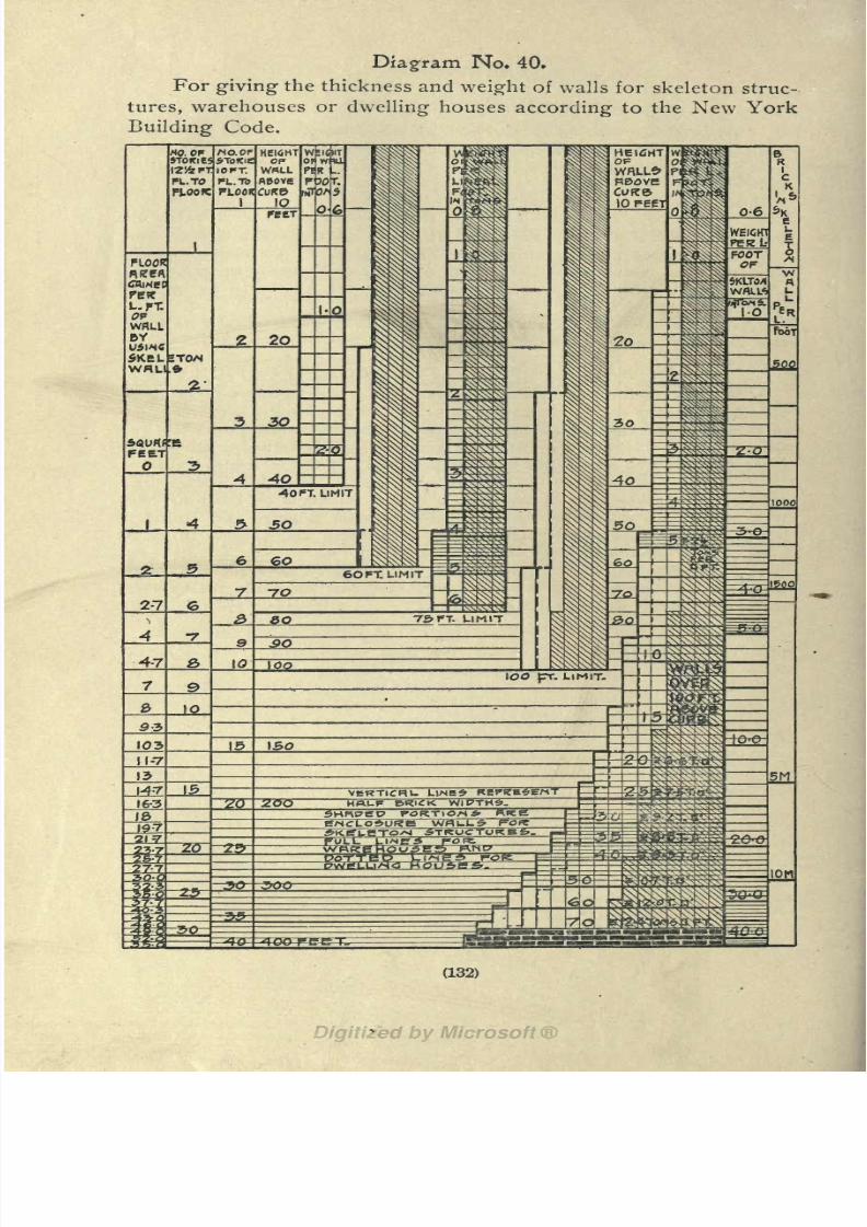
8/8/2019 Structural Design 00 Scot u of t
http://slidepdf.com/reader/full/structural-design-00-scot-u-of-t 145/177
Diagram No. 40.
For giving the thickness and weight of walls for skeleton struc-
tures, warehouses or dwelling houses according to the New York
Building Code.
(132)

8/8/2019 Structural Design 00 Scot u of t
http://slidepdf.com/reader/full/structural-design-00-scot-u-of-t 146/177
GERMAN, BELGIAX AXD ENGLISH I-BEAMS. 133
CHAPTER XIII.
GERMAN,BELGIAN AND ENGLISH
I-BEAMS.
It may be of interest to the designer to compare foreign prac-
tice in rolled beams with American practice. For this reason Tables
Nos. 32, 33 and 34, have been prepared, giving the principal dimen-
sions of I-beams made in Germany, Belgium and England respec-
tively.
GERMAN I-BEAMS : This list of
shapes
is a mostinteresting
series from a theoretical point of view. The increments of increase
of weight, thickness of web and strength follow almost a perfect law
of symmetry. From a practical aspect there is little of value in them
that would appeal to the American mind;there are 27 different
heights between 5^ ins. and 2if ins., inclusive, while the ten dif-
ferent heights adopted by the American Association of Steel Manu-
facturers in 1896 for beams 6 ins. and over already seem too many.
In this table the section-moments are given on a basis of 8
tons per sq. in. allowable fiber stress. These are given more for
comparative than for practical value. In fact, if this table is used
for designing beams, it would be advisable to use only 70% of the
section-moment given, unless the material passes the American
standard inspection.
BELGIAN I-BEAMS: Representative Belgian I-beams are
listed in Table No. 33. These shapes are somewhat nearer the sec-
tions adopted in this country;
there being from two to four dif-
ferent beams rolled for each height. Otherwise, what has been said
as to strength and adaptability of German shapes to American
needs, applies to the beams of this group.
ENGLISH I-BEAMS : Table No. 34 shows a series of English
sections of I-beam. As might be expected, these shapes conform
much more to the American system of rolling I-beams than any
other. The values for the section moments are given on a basis
of 8 tons per sq. in. allowable fiber stress.

8/8/2019 Structural Design 00 Scot u of t
http://slidepdf.com/reader/full/structural-design-00-scot-u-of-t 147/177
S
uoi^oeg
J9d
jo
M ON O\ toOO co N ON O OO O COO ^ ^ ^ *?
M. ? ^ ^1 . ""1 . ^
t^-vo ri 00 N ON ro
5
M COM COM M
\r) if) OOt~-t^ iovrM M fOfOTJ-ri-ir)M' N N
o vo d ooo c\ rj-vd o M
M M M N M CO rf-VO
PROPERTIES
OF
FOREIGN
B
jo
M CO M CO M
d
t^ covo N -4- O -^-
t^M OCSTJ-COtON tocOtOM
rfvoO-00 M to
c^ >ovo O co"O a\ to M co coooM 10 t^VO OOt^<^OM^MMCO
3 I
to ThM^co co
Oco\6 vd
co co rh tovo ^>00 ON M N rj-vo t ON N rtvo M r T^- M ONMI-.MMMMNCSNCOCOTl-tOtO
08! Tj-NOOOVOTj-NMONlvo^-M ONVO
I
Tj-vooOONMcotot^OOON^fOMt^f) \
N CO * to t^OO ON O M CO * to 1^00 O\
d
*- COOO * OM O M Q\t^toco M co*O
00 OOVOCOMOOVOCOMOOVOCOMCO05 I ON IO M t^ C^ OO ^" O *-O "* ^" CO ^T"
^J I totv-ONONCOtOt^OOOMCO^2 1
C^O' N cOri-vo'r^O-.d N 'j-vdoO ONN rj-vo O u-,O'O MMMMMMMMNNCTNNNCOCOCO-^TJ-XO tOVO
O to O co > O ^-00 NtoONVOON*^ "^
MOO OfaOOQ t>-vo VO toto^cocoN-M OO t^O totOOsCOVO 0^-00 NVO Tj-00 N VO rl-OOVO COM CM-
(134)

8/8/2019 Structural Design 00 Scot u of t
http://slidepdf.com/reader/full/structural-design-00-scot-u-of-t 148/177
U9raoj\[
uono9gfOnO\MOO NVOOOOO
ON r^-vo' 06 o\ pi voxi M ri M M oo' od M* 06 oo* -4- -4- M o O ONVO ti-vo d vo oX_,MMMrO'-iN'-iMNNNP<rO'*tcO 1<*-'*'rOvo -^-VO OO O
qeM.
-Con
*O OVO "O vovo VO vovO OVO
LON COCON
jo
10 MN oo
ONO\O\O --^^.uovooOO
T"-v '^*vJflL r,
-U0i;09g I *}
Tt->O rl-CX) COON VONO\LoOt^O N O ** OO ON M M N C\vo
ro LO O vo M LO N"
T*- -^- ir> <* LOLOVO
COVO ONN O\N M rl-toONco LO rovo rovo ro LO rovO fOVO ro^O rj-\o <tvo LOOO LOOO LO t^. LO t^
rOOO rJ-OO rj- r^ r^-00 Tj- r>. Q ro rl-OO COVO P4VONVOOOPJOONOONCNM vot^ONM O N vot->.vot~ONM Osi-< M ^-ONP4 O\P)
vovo
vo vo LO LO LO O
MMM.MCVCiMfiMMMPOMN-C'IC'JPO^* LOVO LOVO LOVO LO **
taB9y; jo
VO* tA. O\ M
I
!%
OO N VO Of> POOO 00fO t^ O 1
^-VO VO ** t^
IAV
S3 00 rOOO * <*
5 w ON Q 00 1^
XI rJ-VO O N ON
aedM fO ro M OCN t^. 10 ^- NVO t^OO ON M
jo
LO LTj Nro M O OO 10r^ t^ t^vo vo
(135)

8/8/2019 Structural Design 00 Scot u of t
http://slidepdf.com/reader/full/structural-design-00-scot-u-of-t 149/177
136 STRUCTURAL DESIGNERS' HANDBOOK.
CHAPTER XIV. FLEXURAL EFFICIENCY OF I-BEAMS
AND CHANNELS.
An interesting matter in connection with the design of beams
and girders is the relative "efficiency" of the different standard sec-
tions. An 8-in. 18 Ibs. I-beam has a certain section moment. If
this beam be taken as a standard of comparison, then the value ofits section-moment divided by 18 may be taken as a unit of effi-
ciency, i. e., 100%. Thus a 2O-in. 65 Ib. I-beam, for instance, shows
a much greater bending strength per pound of metal contained in
a lineal foot of the beam ,
DIAGRAM NO. 41 herewith gives curves representing the rel-
ative efficiency of all the standard and special section of I-beams
and channels. In this diagram abscissas represent efficiencies,
based on the above standard. Ordinates represent weights perlineal foot. Different lines drawn on the diagram represent the
various sections of beams. The full heavy lines represent the
I-beams of the American Association of Steel Manufacturers. The
light full lines represent Pencoyd I-beams (only shown where they
differ considerably from the Association standards). The dotted
lines represent standard and special channels.
As a matter of comparison some foreign sections of I-beams
are also represented on this diagram. The solid dots representsome of the oddest of the Belgian I-beams. The depth of the
beam is in each case noted next the dot in figures representing
inches. In like manner, a number of representative German sec-
tions of I-beams are shown by circles with black centers. The sizes
they represent are given as for the Belgian shapes.

8/8/2019 Structural Design 00 Scot u of t
http://slidepdf.com/reader/full/structural-design-00-scot-u-of-t 150/177
FLEXURAL EFFICIENCY OF I-BEAMS AND CHANNELS. 137
Diagram No* 41
For giving the relative flexure efficiency of I-beams and chan-
nelsper pound
of steel.
50
PERCENTAGE OF EFFICIENCY
50 60 70 80 90 100 2CO 250
100 150
PERCENTAGE OF EFFICIENCY
200 250

8/8/2019 Structural Design 00 Scot u of t
http://slidepdf.com/reader/full/structural-design-00-scot-u-of-t 151/177
138 STRUCTURAL DESIGNERS' HANDBOOK,
CHAPTER XV. BASES AND LINTELS OF CAST IRON.
CAST IRON BASES OR SHOES FOR COLUMNS: These usu-
ally bear upon concrete, dimension stone, brickwork or upon grill-
age footings. They are usually set in place upon small blocks and
grouted with Portland cement paste from one-half to three-fourths
of an inch in thickness. A better practice is to ram the Portland
cement mortar in from the side of the shoe, to do which requires
not less than an inch and a half to two inches of clear space under
the shoe when temporarily supported by the blocks.
The area of the bottom side of this shoe is determined by the
allowable unit pressure on the supporting material. The height
and thickness of metal depend upon a variety of certain and uncer-
tain conditions. Only a few of the more important of these con-
ditions will be considered because they arise in specific cases rather
than in general practice.
Aslight
unevenness in the grouting of a cast iron shoe is not
an unusual occurrence, and this is sure to set up irregular and
indeterminate stresses in the metal. When grillage beams are
used in footings the slightest deflection of the beams will cause the
load on the shoe to be carried on its two edges at right angles to
the beams. The distance of the webs or ribs apart should never
exceed the limits fixed by the strength of the bottom plate between
these webs.
A "rule ot thumb" method of designing cast-iron shoes is to let
h = iH a (25)
where h = height of shoe,
a = projection of shoe beyond the edge of the column.
The thickness of metal is made the same as that of the column sup-
ported.
The purely theoretical methods for computing the flexure
strength of shoes are laborious and tedious. The following sim-
ple empirical formulas give results within a very small percentage
of absolute accuracy. Two cases are considered:
(1) When a uniform unit pressure is assured on the bottom of
the shoe for instance, a bearing on a granite block.
(2) When the load is likely to be carried on two edges of the
shoe a condition existing when grillage footings are used.

8/8/2019 Structural Design 00 Scot u of t
http://slidepdf.com/reader/full/structural-design-00-scot-u-of-t 152/177
BASES AND LINTELS OF CAST IKON. 139
FIRST CASE:-a
2 WA = -
(26)
(2 a + b) h
where a = projection in inches.b =3 diameter of column in inches,
h = height of shoe in inches.
W = total load in tons.
A = area* of cross section (in square inches).
SECOND CASE:-
A = W (27)
h
where the values are same as above.
When the thickness of metal in the various parts of a cast iron
shoe is not uniform, or nearly so, flaws are apt to develop in the
process of the cooling off of the casting. For this reason the de-
sign of an economical shoe requires skill in choosing the height and
distance apart of the webs so that the metal in the several parts
shall be one thickness. The thickness of metal directly under the
column section must always be sufficient for the load on the
column.
The safe limits for the distance between the webs or ribs of
cast iron shoes are given on DIAGRAM NO. 42 herewith. It gives
the safe distance in inches for various unit loads on the bottom of
the shoe and for various thicknesses of metal in the bottom plate.
EXAMPLE: For a unit pressure on the bottom of a shoe of n l/2
tons per sq. ft., the brackets should not be more than 10 ins. apart for i^-in.
metal in the bottom plate, while for 18 tons the metal should be 2 ins. for
the same spacing of brackets.
CAST IRON LINTELS: When the height of the stem of a cast
iron lintel is not less than about 4/10ths of the width of the lintel
per stem, the formulas following can safely be used. Two stems
should be used for widths greater than 16 ins.
B L8 WabA = +
, (28)
115 h 83 L h
where A = area of cross section of lintel at the centre in square inches.
B = thickness of brick wall in inches.
L = span of lintel in feet.
h = height of cross section at centre of lintel in inches.
W= concentrated load (at distance a and b from each end) in Ibs.
(Note: If more than one concentrated load occurs Wab= W a' b' + W" a" b" + etc.
This area includes only the area of the ribs at a distance "a" from the
edge of the shoe plus the area of the base plate.

8/8/2019 Structural Design 00 Scot u of t
http://slidepdf.com/reader/full/structural-design-00-scot-u-of-t 153/177
I4o STRUCTURAL DESIGNERS' HANDBOOK.
Diagram No. 42
For giving the minimum thickness for bottom plate of cast-
iron shoes.
CLEAR DISTANCE BETWEEN BRACKETS
10" 15 20"
Yi
10* 15 20
CLEAR DISTANCE BETWEEN BRACKETS

8/8/2019 Structural Design 00 Scot u of t
http://slidepdf.com/reader/full/structural-design-00-scot-u-of-t 154/177
BASES AND LLVTELS OF CAST IRON. 141
The width required for a lintel is always knowh and in the
case of brick walls is usually 8, 12, 16, 20, 24 or 28 ins., according
to the thickness of the wall above it; with the above formula, by
assuming a height for the lintel, say 6, 8, 10 or 12 ins., and deciding
upon the use of one or two stems, the area of the cross section is
found from the first factor of the above formula if no concentrated
load occurs; and from the summation of the factors when one or
more concentrated loads occur along with the brick wall load.
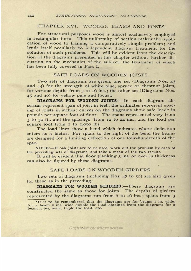
8/8/2019 Structural Design 00 Scot u of t
http://slidepdf.com/reader/full/structural-design-00-scot-u-of-t 155/177
142 STRUCTURAL DESIGNERS' HANDBOOK,
CHAPTER XVT. WOODEN BEAMS AND POSTS.
For structural purposes wood is almostexclusively employedin rectangular form. This uniformity of section makes the appli-
cation of wood to framing a comparatively simple problem ;and
lends itself peculiarly to independent diagram treatment for the
solution of such problems. This will be evident from the descrip-
tion of the diagrams presented in this chapter without further dis-
cussion on the mechanics of the subject, the treatment of which
has been fully covered in Part I.
SAFE LOADS ON WOODEN JOISTS.
Two sets of diagrams are given, one set (Diagrams Nos. 43
and 44) for the strength of white pine, spruce or chestnut joists,
for various depths from 3 to 16 ins.;the other set (Diagrams Nos.
45 and 46) for yellow pine and locust.
DIAGRAMS FOR WOODEN JOISTS: In each diagram ab-
scissas represent span of joist in feet; the ordinates represent spac-
ing of joists in inches;
curves on the diagrams show safe load* in
pounds per square foot of floor. The spans represented vary from
3 to 30 ft., and the spacings from 12 to 24 ins., and the load per
square foot from I to 1,000 Ibs.
The load lines show a bend which indicates where deflection
enters as a factor. For spans to the right of the bend the beams
are designed for a limiting deflection of one four-hundredth of the
span.
NOTE: If oak joists are to be used, work out the problem by each of
the preceding sets of diagrams, and take a mean of the two results.
It will be evident that floor planking 3 ins. or over in thickness
can also be figured by these diagrams.
SAFE LOADS ON WOODEN GIRDERS.
Two sets of diagrams (including Nos. 47 to 50) are also given
for these as in the preceding.
DIAGRAMS FOR WOODEN GIRDERS: These diagrams are
constructed the same as those for joists. The depths of girders
represented by the diagrams run from 6 to 16 ins.; spans from 3
*It is to be remembered that the diagrams are for beams I in. wide;
for a beam 2 ins. wide double the load obtained from the diagram; for a
beam 3 ins. wide, triple the load. etc.

8/8/2019 Structural Design 00 Scot u of t
http://slidepdf.com/reader/full/structural-design-00-scot-u-of-t 156/177
WOODEN REAMS AND POSTS. 143
to 25 ft. arc shown, and loads from I to 100 Ibs. per sq. ft. The
spacing of girders represented by the ordinates is given in feet
and runs from 7 to 18 ft. The limiting deflection is same as in the
preceding diagrams. The diagrams are also for girders I in. wide.
SAFE LOADS ON V rOODEN POSTS.
The strength of wooden posts is represented on Diagram No.
51. The general arrangement of this diagram is similar to those
for steel and cast iron columns. It is constructed on the basis of
the stressesprovided by
the"Code" (N. Y. C.) and is a combina-
tion of three distinct diagrams representing, respectively, white
pine, white oak, and yellow pine. In all three diagrams abscissas
represent column ratios, ordinates represent area of section, and
the curves represent concentric loads.
It will be noted that the upper scale of abscissas differs from
the scale at the bottom of the diagram. The former represents the
ratio of slenderness of the posts as hitherto defined the quotient
of thelength
dividedby
the radius ofgyration
of the cross section
and is given so that Diagrams Nos. 30, 32 and 34 can be com-
bined with it for the purpose of designing wooden posts for
eccentric loads. The latter, the scale at the bottom, represents
another ratio much used for wooden posts : the length divided by
the least width of the section. This latter ratio is the one com-
monly used.
Two supplementary ordinate scales are given at the -right of
thediagram.
The first of these shows the usual sizes ofposts,
at
proper vertical intervals to represent the areas given on the ordi-
nate scale on the extreme left. One column is given for square
posts, another for round posts.
The other supplementary scales show the weight per lineal
foot for any cross section area of post. One column is given for
white pine and another for yellow pine and white oak which woods
are approximately twice as heavy as white pine.
EXAMPLE: Posts of white pine, white oak or yellow pine 10"x
10"
will carry concentric loads of 32 to 18 tons, 36 to 20 tons, or 40 to 23 tons,
respectively, for unsupported lengths of 25 ft. to 8 ft. 4 ins.
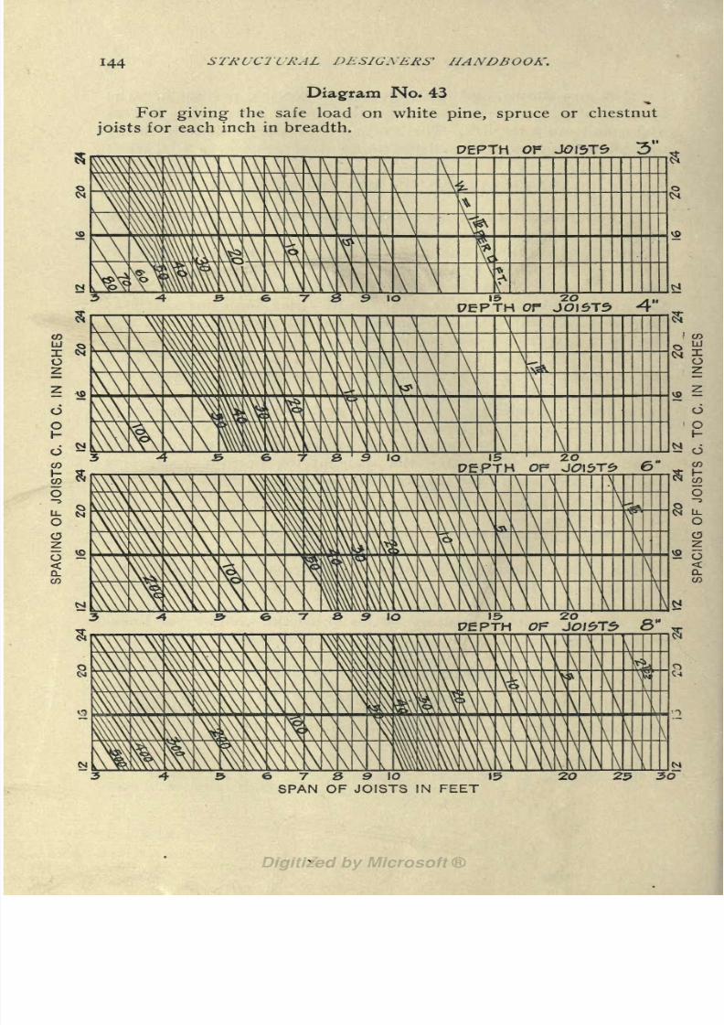
8/8/2019 Structural Design 00 Scot u of t
http://slidepdf.com/reader/full/structural-design-00-scot-u-of-t 157/177
144 STRUCTURAL DESIGXERS' JIANDBOOK.
Diagram No* 43
For giving the safe load on white pine, spruce or chestnut
joists for each inch in breadth.
PERTH OF JOISTS
15 ZO y,
PERTH Or J0I5T5 4
15 20
o
o
PERTH OF J0IS>T6> 6" .
8VA \
A\
V\\ AV
8 9 lo
PEPTH Of &"
\
\\N\\\
\\
\\
7 8 9 10
SPAN OF JOISTS IN FEET20 25 30
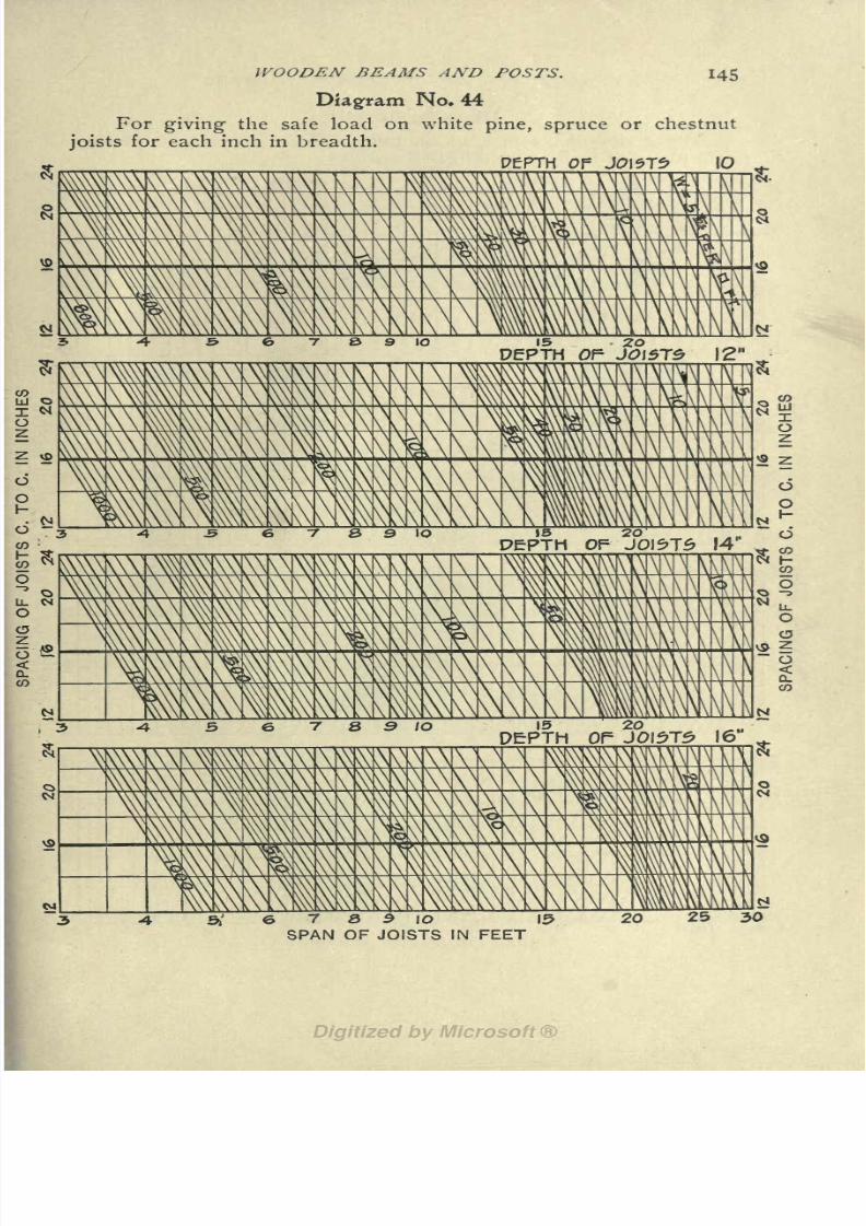
8/8/2019 Structural Design 00 Scot u of t
http://slidepdf.com/reader/full/structural-design-00-scot-u-of-t 158/177
WOODEN BEAMS AND POSTS. 145
Diagram No. 44
For giving the safe load on white pine, spruce or chestnut
joists for each inch in breadth.
PERTH Of JO\5Tf> \O
20PERTH 0P JO\$J5 12"
\\
5 6 7 8 9 IO
\A
N
N
5EPTH OF JOI5T5I6"
6 7 8 $ 10
SPAN OF JOISTS IN FEET
N
25 30

8/8/2019 Structural Design 00 Scot u of t
http://slidepdf.com/reader/full/structural-design-00-scot-u-of-t 159/177
146 STRUCTURAL DESIGNERS' HANDBOOK.
Diagram No* 45
For giving the safe load on long leaf yellow pine or locust
joists for each inch in breadth.
DEPTH OP JOI5T2 3"
mm\\\\\\\\\ v\v\\\^
\ \
DEPTH OP J0I5T5> 4"
15 20DEPTH OP
^XXX^WAVV, M^\\V^\V^-*"Vs
a
o 2=
<D.
0\\\ ^
5 7 S 9 10
s
Or
8N
& 9 10.
SPAN OF JOISTS IN FEET
\\
\\
\\
\\
\\
\\\
\\\\
a
a r-,
20 25N
SO

8/8/2019 Structural Design 00 Scot u of t
http://slidepdf.com/reader/full/structural-design-00-scot-u-of-t 160/177
WOODEN BEAMS AND POSTS.
Diagram No. 46
For giving the safe load on long leaf yellow pine or locust
joists for each inch in breadth.
DEPTH OF JOISTS IO*
\ \
I230
CO
789k) 15
SPAN OF JOISTS IN FEET20 25 3O

8/8/2019 Structural Design 00 Scot u of t
http://slidepdf.com/reader/full/structural-design-00-scot-u-of-t 161/177
148 STRUCTURAL DESIGNERS' HANDBOOK.
Diagram No. 47
For giving the safe load on white pine, spruce or chestnut
girders for each inch in breadth.
Of tflRP&R 6"
\\\\\\\VA\\ \ \ \ \
N
\
\
^
\\v\\
\\\
\ \
\\
S
SSBSSSk
\
A\
NIC
\ \
\1
N
co
B 9 10 J5
DEPTH OF GIRDER 8"
\\\\\\\
\\\\\\\\
VN\A\\\\\
VN\\W\\
\v
^M^
\
\\
^\\
\\\3 9 10 \5>
DEPTH OP GIRDER 10
V>>HNNNN\\\ \\\N\ A'.N'A. V\ \ x^
\\
^x\A.\m
\
\\\\\\\
\\\\\
N^A\\
\\\\
\\N\v\\\X
AN\A
ffi^X
S\
sss
\\
A.Ni
5\5
NN
\\
\\\
s
co
7 a 9 10 \5
SPAN OF GIRDER IN FEET
20 Z5

8/8/2019 Structural Design 00 Scot u of t
http://slidepdf.com/reader/full/structural-design-00-scot-u-of-t 162/177
WOODEN BEAMS AND POSTS. 149
Diagram No. 48
For giving- the safe load on white pine, spruce or chestnut
girders for each inch in breadth.
PEPTH Of- GIRPE-R 12"
X\\\\\\AA_XA
v\\\\ \\
\\\\\\\\\ \NV
\\\\ \\
XV\Y \v
\\K \\
\ fttt AX\\
\\
9 10 \5 20
PfPTH OF GlRPfrR 14
\\ \\ \\ v>\\ \vJQ
oo\ \\
\\\\\\ \v \\ \f
\VV\
\\\
zKMS OLL
O
N ?
^i
\V10 15
PERTH2O
OF GIRPER 16'
\\ \\ A A \ Vv\v \\ \ \ \ \ \ l-\--A\ \\SS \\ \A
\ V \v\ Ift
\\.\\
\\\\'\\ \ vv \AvV N^Cv
1\\\\
ss Vv ^A
^^ 5S\\
& 7 8 9 10 \5
SPAN OF GIRDER IN FEET
20 2530

8/8/2019 Structural Design 00 Scot u of t
http://slidepdf.com/reader/full/structural-design-00-scot-u-of-t 163/177
ISO STRUCTURAL DESIGNERS' HANDBOOK.
Diagram No* 49
For giving the safe load on long leaf yellow pine or locust
girders for each inch in breadth.
PERTH OF ORDER 6"
o
e 10
Q
20 30 LLI
PEPTH Of GIRDER 3"
6 7 5 9 1O 15
SPAN OF GIRDER IN FEET
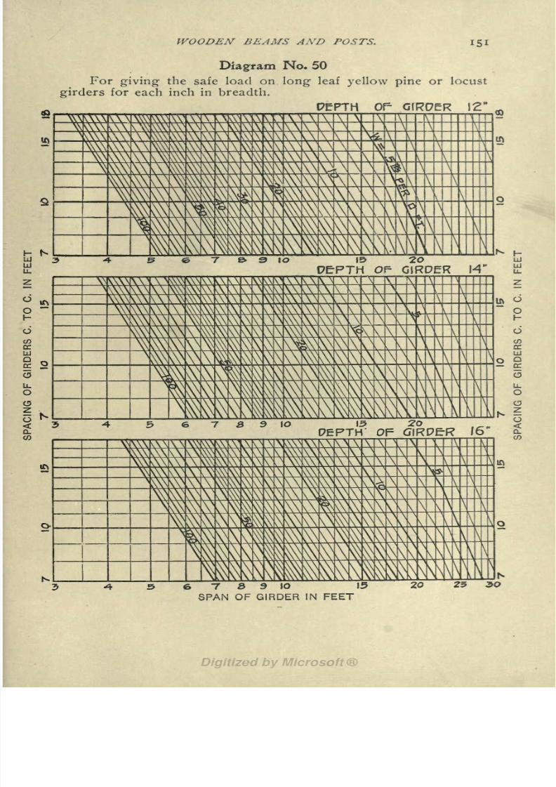
8/8/2019 Structural Design 00 Scot u of t
http://slidepdf.com/reader/full/structural-design-00-scot-u-of-t 164/177
WOODEN BEAMS AND POSTS.
Diagram No* 50
For giving the safe load on long leaf yellow pine or locust
girders for each inch in breadth.
PERTH Of' G1EC7ER 12"
\\
\\
v\\ s\v \\\\\ \\
\\ \\ Y\ \\
\v \\
\\\\v
V9 10 2O
PERTH OP GIRDER
7 B 3 10 15
SPAN OF GIRDER IN FEET
20

8/8/2019 Structural Design 00 Scot u of t
http://slidepdf.com/reader/full/structural-design-00-scot-u-of-t 165/177
152 STRUCTURAL DESIGNERS' HANDBOOK.
Diagram No* 5J
For giving the safe load on wooden posts.
fl is,isii a i a
'an nli nil mlL11 l- l
i*\
\
\\
\ \ \\ \ V \ \\\\
n
\=
^\\ \^\ \ \ \
\
\\
\
\
\\\\ \ \\\ \ \
\\ \\ \ \\\ \
ftTW
ffi \ L\ I
\v\\
\
p\
AREA OF SECTION IN SQUARE INCHES

8/8/2019 Structural Design 00 Scot u of t
http://slidepdf.com/reader/full/structural-design-00-scot-u-of-t 166/177
INDEX.
American Assoc. of Steel Mfrs.:
Standard shapes ................................... 14
Angles :
Radius of gyration ............................... 102106Section area ....................................102106Section moment .................................. 102, 106
Steel:
Table for beams, girders, columns, or truss members
having even and uneven legs ...................102 106
Thickness of metal ............................... 102106(See also Connection Angles.)
Angles and Tees:
Explanation of diagrams for .......................... 14
Base ................................................... 60
Bases, cast iron:
For columns ...................... ............... 138, 140
Beams:
Angles, diagrams described ........................... 14
Belgian I .........................................133135Buckling of compression flange ....................... 4
Cross section ......................................... 1
Definition of ......................................... 11
Deflection ....... . .................................. 2
Diagram, concentrated load converted to uniform load.. 52
Diagram, concentrated load at any point reduced to con-
centrated load at middle ..................... : . . . . 56
Diagram for I-beams, 3-in. to 24-in.............. .... .19 47
Diagrams for angles and tees, spacing and span for given
loa'ding ......................................4851Diagram for grillage beams .................. ......... 63
Diagram, deflection various loadings on 3-in. to 15-in.
I-beams ........................................ 57
Diagram, deflection various loadings1 on 10-in. to 24-in.
I-beams ........................................ 58
Diagram for converting concentrated load to equivalent
uniform load .................................... 15
Diagram, safe loads on 3-in. to 15-in. channels ........ 59
Diagram, spandrel beams ............................. 56
Diagrams, utility of .................................. 11
EnglishI
........................................ 133135End reactions ............................. ........... 3
Explanation of diagrams ............................. 12
Explanation of diagrams for I-beams and channels .... 54
Explanation of tables .............................. 13, 14
Flexural efficiency, I-Beams .......................136, 137
German I ....................................... 133 135

8/8/2019 Structural Design 00 Scot u of t
http://slidepdf.com/reader/full/structural-design-00-scot-u-of-t 167/177
154 INDEX.
Page
Grillage. (See Grillage Beams.)
Loads' 4
Manner of support 2
Maximum end reaction 13
Maximum per cent, of bending load 13
'Mechanics of 1
Method of using diagram for I-beams 12
Properties of 85
Properties of Foreign 134, 135
Resistance 1
Section moment 1
Span 1
Spandrel 53, 54
Steel, I Tables for beams, girders, columns or truss mem-bers
9093Tables for 3-in. I-beams, channels and zees 18
4-in. I-beams, channels and zees 20
5-in. I-beams, channels, zees and bulb angles 22
6-in. I-beaims, channels1
, zees and deck beams 24
7-in. I-beams, channels, zees and bulb angles 26
8-in. I-beams, channels, deck beams and angles.... 28
9-in. I-beams, channels, deck beams and angles. ... 30
10-in. I-beams, channels, deck beams and angles. ... 32
12-in. I-beams, channels and deck beams 34
12-in. I-beams and channels 36
15-in. I-beams and channels 38, 3918-in. I-beams .42
20-in. I-beaons 44
24-in. I-beams 46
Tees, explanation of diagrams 14
Unit stress 2
Beamwork 11
Bearing Capacity of soil 128
Bearing plates:
Design of 67
Tables of . 7071Brick walls. (See Walls, Brick.)
Brickwork, safe load on 68
Buckling of compression flange 4
Buckling of web 62, 64
Cast iron bases and lintels 138
Channels Beams. (See Beams.)
Channels :
Flexural efficiency 136, 137
Height of 94, 96
Section area 9496Tables for beams, girders, columns, truss' members. ...94 97
Web thickness 9496Weight per foot 94101
Channel columns. (See Columns, Plate and Channel.)
Columns:
Base, cast iron or steel 60
Built steel shapes , 88

8/8/2019 Structural Design 00 Scot u of t
http://slidepdf.com/reader/full/structural-design-00-scot-u-of-t 168/177
INDEX.155
PageColumns. Continued.
Cast Iron,
Design of'
112
Diagrams giving safe loads' as recommended by the
author 115Diagrams giving safe loads as specified by New York
Building Code 114
Diagram giving weight in pounds per foot, thickness of
metal and outside diameter 116118Channel 88
Concentric loads 8
Cross section of 9
Diagram for eccentric loading 83
Diagram giving radius of gyration of the most commonforms of built-up sections 80
Diagram giving radius of gyration of the most commonforms of wood, cast iron or steel sections 79
Diagram giving ratio of slenderness 81
Diagram giving safe loads, New York Building Code, for
ratios of slenderness up to 120 and as recommended
by the author for ratios 120 and 200 82
Eccentric loads 8
Footings 60
Mechanics of 1
Plate and angle 89
Radius of gyration 72
Ratios' of slenderness 73
Designing built columns 72
Table for plate and angle 107
Tables for plate and. channel 98101Weights of . 98101Zee-bar 89
Columns and truss members 72
Connection angles:
Bearing values 69
Design of 66
End reaction 67, 69Holes in shop or field end 69
Rivets 70
Shearing values 69
Diagram, explanation of equivalent load on spandrel beams.. 53
Diagrams. (See Beams, Diagrams; Columns, Diagrams, etc.)
Dimensions and weights 85
Dimensions for practical detailing 91 110
End reaction, allowable. (See Beam Tables.)
End reactions 3, 13, 14, 65, 67, 69, 70, 91, 93
Beams:Connection angles 67, 69
Explanation of diagram 65
Floor:
Explanation of diagram for converting concentrated load
to equivalent uniform load 15
Diagram for converting concentrated load to uniform load. 52

8/8/2019 Structural Design 00 Scot u of t
http://slidepdf.com/reader/full/structural-design-00-scot-u-of-t 169/177
156 INDEX.
PageFloor arches:
Weight of 123
Floor beams, wooden:
Weight of 123
Floor framing 11
Diagram giving weight of steel where loads are a mini-
mum 120
Diagram giving weight of steel where loads are a maxi-
mum 121
Floor framing, steel:
Weight of 119
Floor Girders:
Conventional method of treating load on 5
Flooring material:
Weight of 123
Footings 60
Diagram for grillage beams 63
Live load on 125
Foundation walls 131
Girders. (See Beams, Definition of; Plate Girders.)
Grillage beams 60
Conventional methods of considering loads on 7
Explanation of diagram 62
Diagram,safe
pressurein tons
persq. ft 63
Illustration of footing 61
Load on 5
I-Beams. (See Beams.)
Joists, weight per sq. ft. of floor 122
(See also Beams.)
Lattice bars 84, 95, 97
Lintels, cast-iron 139
Load, allowable per sq. ft. (See Beam Tables.)
Loads, dead:
Carried by columns 119Carried by floor girder 119
Loads:
Diagram for eccentric column loading 83
Explanation of diagram for reducing concentrated load
to equivalent uniform load 16
Explanation of equivalent load diagram 53
Loads, live, New York Building Code 124, 125
On beams 4, 57, 58
On columns 8
On floor girders 5
On footing 125
On grillage beams 5, 7
On wooden girders 143, 148 151
On wooden joists 142, 144147On wooden posts 143, 152
Web in compression 9193
8/8/2019 Structural Design 00 Scot u of t
http://slidepdf.com/reader/full/structural-design-00-scot-u-of-t 170/177
INDEX. 157
Page
Partitions:
Weight of 124
Plate and angle columns. (See Columns, Plate and Angle.)
Plate girders':
Design of 87
Properties of 86
Plates, 'bearing. (See Bearing Plates.)
Plates, thickness of 98101
Pressure, wind 1 -">
Properties of Foreign I-beams 134, 133
Radius of gyration 72, 79, 80, 83, 91, 98, 102106, 108110
Diagram common forms', wood, cast-iron or steel sections. 79
Diagram built up sections 80
Rafters. (See Beams.)Reactions. (See End Reactions.)
Retaining walls, thickness of 131
Rivets:
Diameter of 9197Gage of lines 9197Relative values various sizes 69
Size of 102103
Size and gage for zee-bars 110
Rubble, safe load on 68
Section areas:
For concentric loading 75
For concentrically loaded columns with pin ends 76
For eccentric loading 77
For tension members 76
Section moment 1, 9197, 101106, 108, 109
Shapes. (See Structural Shapes.)
Soil, bearing capacity 128
Spacing c. to c. (See Beam Taibles.)
Span, allowable. (See Beam Tables.)
Spandrel beams, explanation of diagrams 53Standard shapes 14
Steel, fl'at rolled, weight of Ill
Steel angles. (See Angles Steel.)
Steel columns. (See Columns.)
Strength of web 9193
Stresses, unit:
Safe load on masonry work 126
Strength of columns 126
Working stresses:
Compression (direct) 127Safe extreme fiber stress (bending) 128
Shear 128
Tension (direct) 128
Structural shapes, properties of 16. 84
Tables. (See Beams, Columns, Connection Angles, etc.)

8/8/2019 Structural Design 00 Scot u of t
http://slidepdf.com/reader/full/structural-design-00-scot-u-of-t 171/177
IS8 INDEX.
PageTees:
Beam diagrams described 14
Dimension and weights' 108, 109
Radius of gyration 108, 109
Section moment 108, 109
Tables for beams, girders, columns or truss members. 108, 109
Template, size of 70
Timber. (See Wood.)
Trusses:
Design of 86
Properties of 86
Unit stresses. (See Stresses, Unit.)
Walls:
Footing 60
Foundation 131
Retaining, thickness of 131
Thickness and weight 129, 132
Walls, brick:
Weight of 124
For dwelling houses 129
For inclosing skeleton structures 129, 131
For warehouses 129
Web:
Buckling of 62, 64
Compression allowable load 91 93
Strength of \ 9193Thickness 94, 96
(See also Beam Table.)
Weight, floor framing. (See Floor Framing.)
Weight, per foot. (See Beam Tables.)
Weight, flat rolled steel Ill
Weights and dimensions per lineal foot 85
Wind pressure 125
Wooden girders, safe loads 143, 148150Wooden joists, safe loads
'
142,144147
Wooden posts, safe loads 143, 152
Zee-bars 89, 110
Flange width 110
For beams, girders, columns or truss members 110
Radius of gyration 110
Size and gage of rivets 110
Thickness of metal 110
Web height . 110
Weight per foot 110
Width of web plate .110

8/8/2019 Structural Design 00 Scot u of t
http://slidepdf.com/reader/full/structural-design-00-scot-u-of-t 172/177

8/8/2019 Structural Design 00 Scot u of t
http://slidepdf.com/reader/full/structural-design-00-scot-u-of-t 173/177

8/8/2019 Structural Design 00 Scot u of t
http://slidepdf.com/reader/full/structural-design-00-scot-u-of-t 174/177

8/8/2019 Structural Design 00 Scot u of t
http://slidepdf.com/reader/full/structural-design-00-scot-u-of-t 175/177

8/8/2019 Structural Design 00 Scot u of t
http://slidepdf.com/reader/full/structural-design-00-scot-u-of-t 176/177
University of Toronto
Library
Acme Library Card Pocket
Under Pat. "Ref. Index Ffl"
Made by LIBRARY BUREAU
8/8/2019 Structural Design 00 Scot u of t
http://slidepdf.com/reader/full/structural-design-00-scot-u-of-t 177/177