Structural Booklet
25
Project Booklet Structural Drafting with AutoCAD
-
Upload
keri-mason -
Category
Documents
-
view
34 -
download
1
description
CAD
Transcript of Structural Booklet

Project Booklet
StructuralDrafting withAutoCAD

iii
Introduction 1
General Setup 2
Border and Title Block 3
Drafting the Foundation Plan (Plate 1) 8
Drafting the South Elevation (Plate 2) 11
Drafting Section A (Plate 3) 14
Drafting Section B (Plate 4) 16
Drafting Details C, C1, and C2 (Plate 5) 16
Drafting Connection Details D, D1, F, F1(Plate 6) 18
Drafting Foundation Details E and E1(Plate 7) 20
Inspecting Your Work 22
Co
nt
en
ts
Co
nt
en
ts

INTRODUCTION
For this project, you’ll prepare a partial set of structuraldrawing using AutoCAD. Essentially, structural drafting is amix of mechanical and architectural drawing methods. Ingeneral, however, the specific drafting techniques used instructural drafting are the same as those used in mechanicaldrafting.
With this project, you’ll put into practice this special combination of mechanical and architectural methods. You’llcreate drawings that would typically be involved in planningand constructing a small storage building. A foundationplan, an elevation, two sections, and several details will bedrafted as parts of seven different drawings for the structuralsteel building.
The information you need to create each of these drawingswill be given in this booklet. However, realize that some ofthe information you may need to draft a particular drawingor detail may be given in descriptions of other parts of thebuilding. Therefore, you should read all the instructionsbefore you actually begin drawing. Your job in this project isto use your drafting skills to clearly and completely reveal—in the seven drawings—all the verbal information presentedhere about the building’s construction.
You won’t need to print or plot your drawing. When you’refinished with the project, you’ll submit the cover sheet at theback of this booklet and a disk containing the electronic datafile for grading.
1
Structural Drafting with AutoCAD

Structural Drafting with AutoCAD2
Your drawings will be for a two-story storage building with aflat roof. The roof is sloped so rainwater drains toward thebuilding’s center. The sides of the roof are about 25″ to 30″higher than the roof’s surface. The only opening into thebuilding you’ll be dealing with is a large sliding glass door onthe first floor. The drawings will be drafted according to theinstructions listed here.
GENERAL SETUP
• Use the AutoCAD settings listed here when specifyingyour units and style.
1. Units. Set the architectural units to 64ths. Usesurveyor’s units for the system of angle measure-ment.
2. Style. Use ROMANS style with ROMANS font. Use0.00 as text height and 1.00 as text width. Defaultthrough the remaining style settings.
• Use the information listed here when setting up your layers.
1. One of the best habits you can develop when usingAutoCAD is that of carefully defining your layers.The layer names should be descriptive, and thecolor and linetype of all your entities should beassigned by layer. Thus, if one of your layers isnamed Concrete, and that layer is assigned thecolor yellow, than any entity drawn on that layerwill be yellow. If you want to make all Concreteentities red, you can simply change the color in the Layer Control dialogue box to red. On the otherhand, if you’ve drawn a circle on the red Concretelayer but have assigned that circle the color green,to change the circle to a different color, you mustactually change the color property of the circle toBylayer.
Developing the habit of assigning color and line-type by layer and using only descriptive layernames will help you keep the elements of yourdrawings standard. In addition, if you decide toexchange drawing files with drafters in other firms,the drafters will be able to easily change layer

colors for plotting with their own plotters.Exchanging drawing files in this way is a commonpractice. Some government bureaus, for instance,may require copies of your electronic files whenissuing building, sewer, or electrical permits.
2. We’ll tell you what layers to use with the founda-tion plan (Plate 1) of this project. For the remainderof the drawings, you must create your own layersusing the recommendations just described. Assigncolors to the layers using the guidelines listed inTable 1.
BORDER AND TITLE BLOCK
One of the many benefits of using AutoCAD is that you aren’trestricted to the size of a drawing surface. Thus, you don’treally need to plan your drawing for space available beforeyou begin drafting.
• Initially, you can create all your drawings using actualmeasurements. For most of these drawings, you’ll leavethem in their actual measurements. A border (with a titleblock) will then be placed around each drawing at theproper scaling factor for plotting. As an alternative, youcould scale a drawing down so that it fits within a certainborder, and then plan to plot the drawing at a scale of 1 = 1. However, doing so alters the actual dimensions. Ifyou later make any changes to the drawing, you’ll find it more difficult to maintain accuracy.
Structural Drafting with AutoCAD 3
1elbaT
SREYAL
roloCreyaLsihtesU epyteniL
deR nihT
wolleY nihTmuideM
neerG kcihTmuideM
nayC kcihT
:setoNtxetllamsyrevdna,senilneddih,sliatedllamsynarofsenilnihtesU.1
.txetlamronrofdnastcejbofoseniltuolamronehtrofsenilnihtmuidemesU.2.txetegralrofdnadezisahpmeebotseniltuoynarofsenilkcihtmuidemesU.3
.redrobretuos'etalpehtgniwardrofdnakcolbeltitehtgniniltuorofsenilkcihtesU.4

• Not all of the drawings in this project will have the samescale (for plotting), even though they’ll all be drawn usingactual measurements. The same border will be used forall your drawings; it can simply be scaled up to the proper size for each of them. Draw the border at a scaleof 1 = 1 using the instructions listed here.
1. Draw the outside trim line using a polyline. Draw it on Layer Hidden, assigning this layer a red colorand a hidden linetype. Make the dimensions forthe trim line 11″ high and 17″ wide.
2. Draw a solid polyline border 1/2″ inside the trimline. Draw it on Layer Border, assigning the layer acyan color and a continuous linetype. As an alter-native, you can OFFSET the trim line 1/2″ and useCHPROP to change the new polyline to Layer Border.
3. Box out the title block by drawing a line 1″ fromthe border’s right side. Draw it on Layer Border2,assigning this layer a green color and a continuouslinetype. As an alternative, you could OFFSET theborder line 1″, use CHPROP to change the new poly-line to Layer Border2, EXPLODE the polyline, ERASE
the top, and EXTEND the line to the cyan border.
4. Figure 1 shows how the title block will be dividedinto different sections. The line you’ve just drawnis the top horizontal line in the figure, the lineabove the XXX where each plate’s title will later bekeyed in. Draw a line 1/4″ away from the last lineyou drew. Draw it on Layer Border2. (In Figure 1,this is the line running under the XXX that holdsthe place for the title.) As an alternative to actuallydrawing this new line, you could simply OFFSET thelast line drawn.
Structural Drafting with AutoCAD4
FIGURE 1—When oriented so the text in the block is running from left to right, your title block willlook similar to this. Fill in the information that will stay the same on each plate, and use XXX to holdthe place for any information that will change from plate to plate.

5. Create a Layer Text-Med, assigning it a yellow colorand a continuous linetype. Find the exact center ofthe area formed between the last two lines drawn.(The dimensions of this area are 10″ × 1/4″.) Maketext in this area using the DTEXT command, theJustify option, and the Middle option. Make thetext 5/32″ high with a north rotation angle. Type theletters XXX for your text. You’ll be using this sameborder for the different drawings; therefore, you’lllater need to change this text to each plate’s actualtitle.
6. In the right corner of your title block, inside thecyan lines, make a square that’s 3/4″ on each side.The new line you need to draw to complete thissquare should be on Layer Border2. Type the textPLATE in the left corner of this square. Use thestandard setting, and make the text left justified.The text should be 5/64″ high with a north rotationangle. Put this text on Layer Text-Med.
7. Create a layer named Text-Large with a green colorand a continuous linetype. In the middle of thesquare, prepare to type in some middle-justifiedtext 3/16″ high with a north rotation angle. TypeXXX in the middle of the square. (You’ll changethis text later to each plate number.)
8. In your title block, section off the boxes containingthe student number and scale. You could OFFSET aside of the plate-number box 2 1/16″ farther into thetitle block. You’ll then have created an area that’s3/4″ × 2 1/16″. Draw a line to divide this area in halfand so create two areas, each 3/8″ × 2 1/16″.
9. With ORTHO on, copy the text PLATE into the areafor your student number. Using DDEDIT, change thetext to STUDENT NO. You can also quickly copyPLATE to the new location by using the ENDPOINT
snap.
10. With ORTHO on, copy the text STUDENT NO. to the area in the box that you’ll use to show thedrawing’s scale. Using DDEDIT, change the text toSCALE:.
Structural Drafting with AutoCAD 5

11. Type XXX into the scale box you’ve just created.Use the standard setting and make the text leftjustified. The text should be 3/32″ high with a northrotation angle. Put this text on Layer Text-Med.You can later change this text to the scale for eachplate.
12. With ORTHO on, copy the text XXX to the box foryour student number. Use DDEDIT to change thenew text to your actual student number.
13. OFFSET one side of the 3/4″ square 4 11/32″ toward the middle of the title block. Doing so creates thebox for the program, title, and date. Create a layer named Text-Small with a red color and a continuous linetype. Using this layer, draw a linethat’s 9/64″ away from the cyan border. Make thelength of this line fit appropriately within the area.OFFSET this line 3/16″ away, and OFFSET the new lineanother 3/16″ away. These three lines are for thedate, project title, and program name. You shouldhave 15/64″ between the line for the program nameand the green Border2 line running under thedrawing title.
14. Copy the text STUDENT NO. to the last red lineyou created. Edit the text to PROGRAM. Using theMultiple option, copy PROGRAM to the other twored lines. Edit the text on the middle line to TITLEand the text on the other line to DATE as shown inFigure 1.
15. Copy your student number to the program line.(This text, on layer Text-Med, should be 3/32″ highwith a north rotation angle. Use the LIST commandto ensure the text has these features.) Change thetext to read AutoCAD DRAFTING.
16. Using the Multiple option, copy AutoCAD DRAFT-ING to the other two red lines. Change the text onthe middle red line to PROJECT 5, and change thetext on the other line to XXX. You can change thistext to the actual date when you complete yourdrawings.
Structural Drafting with AutoCAD6
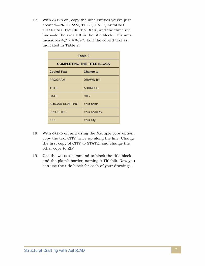
17. With ORTHO on, copy the nine entities you’ve justcreated—PROGRAM, TITLE, DATE, AutoCADDRAFTING, PROJECT 5, XXX, and the three redlines—to the area left in the title block. This areameasures 3/4″ × 4 29/32″. Edit the copied text asindicated in Table 2.
18. With ORTHO on and using the Multiple copy option,copy the text CITY twice up along the line. Changethe first copy of CITY to STATE, and change theother copy to ZIP.
19. Use the WBLOCK command to block the title blockand the plate’s border, naming it Titleblk. Now youcan use the title block for each of your drawings.
Structural Drafting with AutoCAD 7
2elbaT
KCOLBELTITEHTGNITELPMOC
txeTdeipoC otegnahC
MARGORP YBNWARD
ELTIT SSERDDA
ETAD YTIC
GNITFARDDACotuA emanruoY
5TCEJORP sserddaruoY
XXX yticruoY

DRAFTING THE FOUNDATIONPLAN (PLATE 1)
• Draft the foundation plan at actual size.
• The dimensions of the building are given to the center of the structural steel columns. All of the columns in thebuilding are I-beams with the designation of W12 × 152.For the dimensions associated with this designation, consult Appendix H in your supplement containing theappendices and glossary. Create a layer named W12 ×152 with the color yellow and a continuous linetype.
• The building has 20 steel columns—14 spaced aroundthe building’s perimeter and six within the interior.Arrange these I-beam columns on the foundation plan infour evenly spaced rows of five beams each. The distancebetween the center of the beams in adjacent rows is 18′-0″. The distance between the center of adjacent beams in each row is also 18′-0″. The overall dimensions of thebuilding are therefore 54′-0″ × 72′-0″. (Put your dimen-sions on layer Text-Med, with a yellow color and a continuous linetype.)
• When laid out on the foundation plan, the steel columnsare shown with their flanges running horizontally. (Inother words, when you view the plan with the draftingplate turned so that its long edge is on the bottom, thesymbol you make for each steel column will look like an “I.”)
• The dimensions of the concrete footings placed under allthe steel columns are 16 × 32 × 32. The steel columnsare centered over these footings. (Create a layer calledFooting, with a yellow color and a continuous linetype.)
• In between adjacent steel columns is a W12 × 45 steelgirder. There are thus 31 of these girders. The girderssupport the building’s second floor. Again, consultAppendix H in your appendices supplement for thedimensions for this structural steel shape. Draw the girders on a layer called Girders, with a green color and a continuous linetype.
• Running horizontally between adjacent girders are 24steel channel beams. There are two channel beams ineach 18′-0″ bay, and they’re spaced 6′-0″ apart. Thebeam designation is C9 × 20, and its dimensions can befound in Appendix H. The channel beams rest on the
Structural Drafting with AutoCAD8

bottom flanges of the girders. There’s a 1″ gap from theweb of the girder to the end of the channel. Put thesechannel beams on layer C9 × 20, with a yellow color anda continuous linetype.
• Each channel beam is bolted to the girder with a 1/2″thick angle. Each leg of the angle is 4″, and the angle is6″ wide. There are two angles used for each channelbeam, one at either end of the channel. The angle is bolted to the backside of the channel using two 5/8″ Øbolts that are 2 1/2″ long. Each bolt is positioned 1 1/2″away from the end of the angle as well as 1 1/2″ awayfrom the nearest side of the angle. Two more bolts withthe same dimensions fasten the other leg of the angle tothe web of the girder. These other two bolts are also positioned 1 1/2″ away from the end of the angle as wellas 1 1/2″ away from the nearest side of the angle.
• The drawing would be plotted at a scale that will resultin a finished 11″ × 17″ plot. You can figure out an appro-priate plotting scale by first inserting you Titleblk borderinto the drawing.
1. Insert the block at a scale of 1 = 1.
2. Instead of extension lines, draw centerlines upfrom the five I-beams at the top of your drawing.From the four I-beams on the left of the drawing,again draw centerlines instead of extension lines.
3. Mark off with a bubble each of the nine centerlinesyou’ve extended out from the structure. At the topof the drawing, number the bubbles, from left toright, 1 through 5. At the left of the drawing, letterthe bubbles, from top to bottom, A through D.Make the circle for each bubble and the text insidean appropriate size.
4. In a way similar to what’s shown in Figure 21-20b(page 10 in Structural Drafting with BasicArchitectural Applications), give the dimensions for the width and depth of the bays. For thesedimensions, place your dimension lines betweenthe perimeter of the structure and the numberedand lettered bubbles. Past the bubbles, placeanother set of dimension lines to show the widthand depth of the entire structure.
Structural Drafting with AutoCAD 9

5. Show two cutting plane symbols similar to the one shown as Option 3 in Figure 21-5 (page 4 inStructural Drafting with Basic ArchitecturalApplications). The first section’s letter is A, thesheet that locates the section is 1, and the sheetwhere the drawing of the section is shown is 3.Make the circle for the symbol and the text anappropriate height. Place the symbol so that itpoints to the top of your drawing, and place itbetween rows B and C. Show the section line cutting through the entire building.
6. The letter for the second section is B, the sheetthat locates the section is 1, and the sheet wherethe drawing of the section is shown is 4. Copy thesymbols you created for Section A, editing appro-priately. Place the new symbol so that it points tothe left, and place it between columns 2 and 3.Show the section line cutting through the entirebuilding.
7. Place a north arrow at the bottom of your drawingso that it indicates the long side of the building(which will be at the top of the sheet) as the northelevation. Angle the north arrow slightly at a direction of N12°14′0″E.
8. Next to the north arrow, create the underlined textFOUNDATION PLAN. Put the text on layer Text-Large, with a green color and a continuous line-type.
• After you’ve scaled the title block and placed it aroundthe drawing, EXPLODE the block and edit the appropriatetext.
1. Title this drawing FOUNDATION PLAN.
2. Fill in the scale.
3. Change the plate number to 1.
Structural Drafting with AutoCAD10

DRAFTING THE SOUTH ELEVATION (PLATE 2)
Some parts of the elevation can’t be accurately describedwithout examining the building’s section. Use the informa-tion listed here, then either calculate the additional information you need or draw the building section first toreveal the information you’re missing.
• The finish grade elevation is 292.90, the first-floor elevation is 293.90, and the second-floor elevation is305.19. The distance from the top of the footings to thefinish grade is 4′-0″.
• A 2 × 4 keyway is centered at the top of each footing.Centered over each footing is a concrete pillar that’s 16″wide on each side and 4′-0″ tall. At the 4′-0″ height, theconcrete angles away from the pillars at the 45° angle for a vertical and horizontal distance of 6″. This heightmarks the bottom of the 6″ poured-in-place concrete slabmaking up the first floor. This concrete slab rests on an8″ thick layer of compacted sand, which rests on earth.
• The pillars at the four corners of the building are differ-ent from the other pillars. These corner pillars have aheight of only 2′-6″ before the concrete begins to angleaway. The concrete angles away from the pillar at a 45°angle for a vertical and horizontal distance of 2′-0″.
• A 4″ drain is set around the outside of the building, with3″ clear above the footings to the drain and 3″ clear fromthe pillars to the drain.
• The rebar in the bottom of the footings is #6 rebar at 8OC both ways. The callout for the rebar is as follows:
#6 Ø @ 8″ O.C. BOTH WAYS
• There’s 3″ clear at the bottom of the footing and 3″ clearall around. Vertical and horizontal rebar is placed in the pillar similar to that shown in Problem 21-4, (page45 in Structural Drafting with Basic ArchitecturalApplications). This rebar is also #6 rebar at 8″ OC. Theoverlap of the rebar near the bottom of the pillar isapproximately 2″.
Structural Drafting with AutoCAD 11

• A steel plate is centered over each footing at the top ofthe first-floor concrete slab. The plate is 14 × 14 × 1/2.The W12 × 152 steel column is welded to the plate. Theweld is a 1/2″ fillet weld. An example of how such a weldwould look in a simple joint is shown here in Figure 2.The weld symbol—as it should also appear in a detail of the joint on your drawing—consists of an arrow, twotriangular “fillets,” and the size designation. Note that thetriangular shape appears on both sides of the horizontalline. The use of two triangles on the symbol indicatesthat the weld is made on the arrow side of the joint aswell as on the opposite side. If the required weld wereonly on the arrow side of the joint, the triangle wouldappear on only the bottom part of the horizontal line.
The plates are bolted to the concrete slab with twoanchor bolts that are each 1 1/2″ in diameter and 18″long. The bolts project out of the concrete slab 3 1/2″. Thebottom 4″ segment of the bolt is bent horizontal, pointingtoward the center of the building. The center of the boltis 8” from the outside wall. The callout for these bolts islisted here.
(2) 1-1/2″ Ø × 18″ STD. AB. W/3-1/2″ PROJ. @ EA. COL.
• Metal siding (26 gage) is installed on both the outsideand the inside of the building. The shape of the siding is similar to the steel deck shown in Figure 21-12 (page 6 in Structural Drafting with Basic ArchitecturalApplications). The vertical dimension from the bottom, ortrough, of the siding to the siding’s top, or crest, is 1 1/2″.The slope of the angled portions is 60° from horizontal.
Structural Drafting with AutoCAD12
1/2 LEG”
1/2 LEG”
1/2
FIGURE 2—Use a weld symbol likethe one shown here on your detail ofthe connection between the steel col-umn and the foundation.

The length of each horizontal section is 2″, and the metalis 1/4″ thick.
• The clear distance from the first floor to the bottom ofthe first-floor ceiling is 10′. The clear distance from thesecond floor to the bottom of the second-floor ceiling is8′. The distance from the first floor to the top of thebuilding is 22′-7″.
• A supply entrance to the lower floor is on the building’ssouth side. It’s a sliding glass door centered betweencolumns 3 and 4. The rough opening for the door is 12′wide and 8′ high. Above the rough openings is a steel I-beam header, W10 × 45. The header is placed so that the flanges are horizontal and the web is vertical. Theheight of the header is 10 1/8″.
• Several components of the building were described inthis section of your project booklet. You’ll use some ofthe information when drafting details later on. For yourdrawing of the building’s south elevation, however, labelonly the items listed here, complete with their varioussize descriptions (such as “26 gage” or the item’s dimen-sions and so forth).
1. Door header
2. 6′ × 8′ sliding door, (The word sliding can be abbreviated SLD.)
3. Siding
4. Elevations of finish grade, first floor, and secondfloor. (The word elevation can be abbreviatedELEV.)
• In your drawing, remember to show the concrete footings, the steel columns, and the southern roofline as hidden lines.
• Use texture lines to show the siding in small patchesonly. Filling in the entire surface with texture lines on adrawing is unnecessary and can be visually distracting.Doing so may also conceal features that are shown onlyin that particular view.
• Show a line for the finish grade. Show a patch of earth below the finish grade. (Refer to Figure 21-59 onpage 31 of Structural Drafting with Basic ArchitecturalApplications.)
Structural Drafting with AutoCAD 13

• After you’ve scaled the title block and placed it aroundthe drawing, EXPLODE the block and edit the appropriatetext.
1. Title this drawing SOUTH ELEVATION.
2. Fill in the scale.
3. Change the plate number to 2.
DRAFTING SECTION A (PLATE 3)
You’ll use the information given here extensively when draw-ing the building’s details. For drawing the section, however,you’ll need to be concerned primarily with the accuracy ofoverall dimensions. A section shows an overall view of howthe building is constructed. Sometimes it’s impossible toconvey all the information about a building’s construction ina full section. Some of the smaller features, therefore, mayneed to be omitted for clarity. In your drawing of Section A,you may choose which features to omit. The dimensions ofthese features, however, need to be taken into account todraw an accurate overall view. You may find it helpful todraft some or all of the details first, before drawing the section.
• The second floor is made up of a steel deck system simi-lar to that shown in Figure 2112 (page 6 in StructuralDrafting with Basic Architectural Applications). The rebar within the poured-in-place concrete slab is #4rebar at 12″ OC both ways. The steel decking has thesame dimensions as the building’s steel siding.
• Installed below the C9 × 20 beams are 1/2″ ceiling tiles.
• The roof is also made up of a steel deck system. The top of the concrete slab, however, slopes toward the roof drain at a rate of 1/8″ every 1′-0″. A roof drain ispositioned between columns 2 and 3 and between rows A and B. The drain is similar to the one shown inthe second part of Figure 21-56 (page 6 in StructuralDrafting with Basic Architectural Applications). Estimatethe dimensions of the roof drain, and include the noteROOF DRAIN, SEE MECHANICAL DETAILS on yourdrawing.
Structural Drafting with AutoCAD14

• Welded wire fabric is part of the steel deck system for theroof. The wires are #12 gage, and the spacing is 6″ oncenter. To see how welded wire fabric can be indicated ona drawing, look at Figure 21-8 (page 5 in StructuralDrafting with Basic Architectural Applications). There’s a3″ clearance from the edge of the wire fabric to the walland a 3″ clearance from the wire fabric to the bottom ofthe steel deck system.
• The outside walls of the building continue up beyond theroof, creating a short wall around the roof area. The topof the wall is capped with a 14″ wide steel plate welded tothe top end of the steel column. The weld is a 1/2″ filletweld. The 14″ wide steel plate is 1 1/2″ thick at its exterioredge and slopes toward the building interior at a rate of1/4″ every 1’-0″.
• Flashing is installed over the plate and is sloped towardthe building interior. The flashing is 1/4″ thick andextends down the side of the walls approximately 8″.
• Several details are circled on this view. The details areshown at a larger scale on other drafting plates. Whenindicating the details, circle the area to be shown andattach a “detail bubble”—similar to the “cutting planebubble” but without the arrow. (Refer again to Option 3in Figure 21-5 on page 4 of your Structural Draftingstudy unit.) The first detail is the Roof Detail at thebuilding’s easternmost side. Letter this Detail C, andshow it on Plate 5. The next detail is the second-floorconnection at B4. Letter this Detail D, and show it onPlate 6. The next detail is the footing and first-floor connection at the building’s easternmost side. Letter thisDetail E, and show it on Plate 7.
• Label the elevations as well as the vertical dimensions.
• After you’ve scaled the title block and placed it aroundthe drawing, EXPLODE the block and edit the appropriate text.
1. Title this drawing SECTION A.
2. Fill in the scale.
3. Change the plate number to 3.
Structural Drafting with AutoCAD 15

DRAFTING SECTION B (PLATE 4)
• Much of the work you did to produce Section A can beused again for Section B. Keep in mind, however, thatseveral things will be different. For example, you’ll beseeing the cross section of the channel beam instead ofthe flat side of the beam as shown in Section A.
• A detail is circled on this view. Again, use a “detail bubble.” The detail shows how one of the C9 × 20 beamsconnects to a girder. Letter this Detail F, and show it onPlate 6.
• Label the elevations as well as the vertical dimensions.
• After you’ve scaled the title block and placed it aroundthe drawing, EXPLODE the block and edit the appropriatetext.
1. Title this drawing SECTION B.
2. Fill in the scale.
3. Change the plate number to 4.
DRAFTING DETAILS C, C1, ANDC2 (PLATE 5)
• Plate 5 contains three details. The first detail shows thetop of the wall and details the connection of the roof tothe outside wall. This detail is called the Roof Detail and,as usual, will be drawn at actual size. On this detail,however, you’ll indicate two areas that will have furtherdetails. The first detail will be shown at twice its actualsize, and the second detail will be shown at four times itsactual size. (Be careful to remember that these twodetails are shown at different scales.) The first of thesetwo details is the Cap Detail, which you should label C1.The second detail is the Connection Detail, which youshould label C2.
• Plate 5 would be plotted at a scale of 1/2″ = 1′-0″. Todetermine what scale the title block should be, calculatehow many one-half inches are in one foot. This calcula-tion will give you the appropriate ratio number. After you determine the proper ratio, set the LTSCALE to this number, and figure out the text height you want to use.
Structural Drafting with AutoCAD16

• For the Roof Detail, which is labeled C, indicate the itemslisted here, along with their size descriptions.
1. Poured-in-place concrete slab, sloped 1/8″ every 1′-0″ toward the roof interior
2. Welded wire fabric
3. Ceiling tiles
4. C9 × 20 beam
5. Steel decking
6. Metal siding
7. Steel column
• For the Cap Detail, which is labeled C1, indicate theitems listed here, along with their size descriptions.
1. Flashing
2. 14″ wide steel plate
• For the Connection Detail, which is labeled C2, indicatethe items listed here, along with their size descriptions.
1. Interior metal siding
2. Exterior metal siding
3. The angle
4. Width of the angle
5. Bolts
6. Measurements for the placement of the bolts
7. Clearance of the beam from the girder
8. Clearance of the welded wire fabric from the edge of the concrete
9. Clearance of the welded wire fabric from the topof the beam
• Arrange the three details into the space available withinthe frame that contains your title block. Ensure thedetails are spaced appropriately and that the entiredrawing is easy to read.
Structural Drafting with AutoCAD 17
• When you’re satisfied with the placement of the detailsand callouts, EXPLODE the block and edit the appropriatetext.
1. Title this drawing ROOF DETAILS.
2. Designate the scale as VARIES.
3. Change the plate number to 5.
DRAFTING CONNECTION DETAILSD, D1, F, F1 (PLATE 6)
• Plate 6 displays four connection details. Two of thesedetails (lettered D and F) contain the connectionsenlarged in Details D1 and F1. Connection Detail Dshows the connection at B4 from Plate 3. This connec-tion detail is drawn actual size. Indicate on it the area forDetail D1, which will show the connection of the beamsto the girder at four times the actual size. ConnectionDetail F shows the connection of the C9 × 20 beam fromPlate 4. Like Detail D, Connection Detail F is drawn atactual size. On this detail, indicate the area for Detail F1,which will show the connection of the beam to the girderat four times the actual size. Thus, two of the four detailson Plate 6 won’t be done at actual size.
• Plate 6 would be plotted at a scale of 1/2″ = 1′-0″. Todetermine what scale the title block should be, calculatehow many one-half inches are in one foot. This calcula-tion will give you the appropriate ratio number. After you determine the proper ratio, set the LTSCALE to thisnumber, and figure out the text height you want to use.
• For Connection Detail D, indicate the items listed here,along with their size descriptions.
1. Poured-in-place concrete slab
2. Rebar
3. Ceiling tiles
4. Beam
5. Steel decking
6. Siding
7. Steel column
Structural Drafting with AutoCAD18
• For Connection Detail D1, indicate the items listed here,along with their size descriptions.
1. Clearance of rebar to top of beam
2. Beam
3. Girder
4. The angle
5. Width of the angle
6. Bolts
7. Placement of the bolts
8. Clearance of the beam from the girder
• For Connection Detail F, indicate the items listed here,along with their size descriptions.
1. Concrete slab
2. Rebar
3. Ceiling tiles
• For Connection Detail F1, indicate the items listed here,along with their size descriptions.
1. Beam
2. Decking
3. Girder
4. Clearance of the rebar from the girder
5. The angle
6. Width of the angle
7. Bolts
8. Placement of the bolts
• Arrange the four details into the space available withinthe frame that contains your title block. Ensure thedetails are spaced appropriately and that the entiredrawing is easy to read.
Structural Drafting with AutoCAD 19
• When you’re satisfied with the placement of the detailsand callouts, EXPLODE the block and edit the appropriatetext.
1. Title this drawing CONNECTION DETAILS.
2. Designate the scale as VARIES.
3. Change the plate number to 6.
DRAFTING FOUNDATION DETAILSE AND E1 (PLATE 7)
• Plate 7 displays two details: a foundation detail and aconnection detail. The foundation detail, lettered E,shows the outside footing, pillar, and column connectionat the first floor. Draw this detail at actual size. Indicateon it the area for Detail E1, which will show the connec-tion of the steel column to the first floor at four times itsactual size. Remember that this connection detail isn’tdrawn at actual size.
• Plate 7 would be plotted at a scale of 1/2″ = 1′-0″. Todetermine what scale the title block should be, calculatehow many one-half inches are in one foot. This calcula-tion will give you the appropriate ratio number. After you determine the proper ratio, set the LTSCALE to thisnumber, and figure out the text height you want to use.
• For Foundation Detail E, indicate the items listed here,along with their size descriptions.
1. Steel column
2. Metal siding
3. Concrete slab
4. Dimensions of concrete slab
5. Rebar
6. Sand
7. Dimensions for compacted sand
8. Finish grade
9. Footing
10. Dimensions of footing
Structural Drafting with AutoCAD20

11. Keyway
12. Rebar in footing
13. Dimensions of rebar in footing
14. Clearances of rebar in footing
15. The 4″ drain
16. Clearances for the 4″ drain
17. Rebar in pillar
18. Clearances of rebar in pillar
19. Dimensions of the pillar
20. Distance from the top of the footing to the firstfloor
21. Distance from the top of the footing to 45° angle
22. Distance from 45° angle to bottom of concrete slab
• For Connection Detail E1, indicate the items listed here,along with their size descriptions.
1. Steel column
2. Metal siding
3. Anchor bolt
4. Plate
5. Weld symbol
6. First floor
7. Finish grade
8. Distance finish grade to first floor
9. Distance from center of anchor bolt to exterior edgeif concrete
10. Distance from center of anchor bolt to end ofanchor bolt. Note that this anchor bolt is bent horizontal near its end.
• Arrange the two details into the space available withinthe frame that contains your title block. Ensure thedetails are spaced appropriately and that the entiredrawing is easy to read.
Structural Drafting with AutoCAD 21
• When you’re satisfied with the placement of the detailsand the callouts, EXPLODE the block and edit the appropriate text.
1. Title the drawing FOUNDATION DETAILS.
2. Designate the scale as VARIES.
3. Change the plate number to 7.
INSPECTING YOUR WORK
Before sending your cover sheet and disk for grading, exam-ine your drawings for any errors. Make sure your name andstudent number appear on the disk label and on the coversheet. As part of your inspection, consider the followingpoints:
❐ Check for correct shape, size, and placement of entities. Exact placement can be confirmed by checking the coordinates of all lines, points, and arcs.
❐ Check that the entities are on the right layers.
❐ Check to ensure your blocks are the correct size.
❐ Use the ERASE command to delete any unwantedmarks.
❐ Make sure your name and student number appear onthe disk label and on the cover sheet.
When you feel confident that your work is complete, save thedrawing file to a floppy disk. Submit this disk and your coversheet for grading your work. Send in this material as soon asyou complete the project. Don’t wait until your work on thenext project is finished.
Structural Drafting with AutoCAD22

Project Booklet
Structural Drafting with AutoCAD
Grading Criteria
Your drawing will be graded on the following criteria:
Completeness of drawings 20 points _______
Completeness of the title blocks 20 points _______
Accuracy of the Labels 20 points _______
Correct layering of objects 20 points _______
Overall appearance 20 points _______
TOTAL _______
Comments _________________________________________________________________
____________________________________________________________________________
____________________________________________________________________________
PLEASE FOLD THIS COVER SHEET INTO THE DISK MAILER WITH YOUR DISK CONTAININGYOUR COMPLETED DRAWING FILE. ALSO, BE SURE TO WRITE YOUR NAME AND STUDENTNUMBER ON THE DISK LABEL AND IN THE SPACES PROVIDED ON THIS COVER SHEET.
MAIL YOUR COMPLETED PROJECT TOPenn FosterStudent Service Center925 Oak StreetScranton, PA 18515
ESUS'ROTCURTSNIRUOYROFEDARG YBDEDARG
:REBMUNTNEDUTS 00040450
TNIRPESAELPDACotuAhtiwgnitfarD
________________________________________________EMAN
____________________________________________SSERDDA
_________________________________________________YTIC
ECNIVORP/ETATS EDOCLATSOP/PIZ
❐ .sserddawenasihtfikcehC
ENOHP —
Cut
Alo
ng T
his
Line
.