Structural Behaviour of Cold-Formed Steel of Double C ... · Structural Behaviour of Cold-Formed...
15
ORIGINAL ARTICLE Received: February 20, 2019. In Revised Form: February 21, 2019. Accepted: May 10, 2019. Available online: May 15, 2019 http://dx.doi.org/10.1590/1679-78255515 Latin American Journal of Solids and Structures, 2019, 16(5), e195 1/15 Structural Behaviour of Cold-Formed Steel of Double C-Lipped Channel Sections Integrated with Concrete Slabs as Composite Beams S. O. Bamaga a M. M. Tahir b, * S. P. Ngian c S. Mohamad d A. Sulaiman d R. Aghlara b a Department of Civil Engineering, College of Engineering, University of Bisha, Bisha 61922, Saudi Arabia. E-mail: [email protected] b Institute for Smart Infrastructure & Innovative Construction (ISIIC), School of Civil Engineering, Universiti Teknologi Malaysia, 81310 Johor Bahru, Johor, Malaysia. E-mail: [email protected], [email protected] c Construction Research Centre (CRC), School of Civil Engineering, Universiti Teknologi Malaysia, 81310 Johor Bahru, Johor, Malaysia. E-mail: [email protected] d School of Civil Engineering, Universiti Teknologi Malaysia, 81310 Johor Bahru, Johor, Malaysia. E-mail: [email protected], [email protected] *Corresponding Author https://doi.org/10.1590/1679-78255515 Abstract Cold-formed steel (CFS) construction is widely recognised as an important contributor to sustainability and green construction. Thus, the use of CFS construction is encouraged and had been advanced by innovations in its structural applications. One such innovation that has recently gained popularity is the use of CFS sections in composite construction. The researchers assembled two CFS C-lipped channels back to back to construct I- beam sections for testing. Innovative bracket shear connectors were also developed and inserted between concrete slabs and steel beams in order to provide composite action. The composite beams were drastically stronger and stiffer than non-composite beams. The experimental results were validated theoretically with a high level of correspondence. The proposed composite beams with CFS sections were found to be strong and stiff enough to be used in the construction industry. Keywords cold-formed steel, shear connector, composite beam, concrete slab, strength capacity, partial shear connection 1 INTRODUCTION Cold-formed steel (CFS) sections have become increasingly popular in the past decade [1-9], and the effectiveness of applying CFS sections to beams has been postulated by professionals in the construction industry [4]. In developed countries, CFS is used prominently in the structural members of sustainable buildings [10]. However, CFS sections are primarily designed to be non-composite members used for framing, roof trusses on metal buildings, and racks [11]. The application of CFS is currently limited because its thinness can lead to buckling. Composite steel-concrete beams, conversely, are more extensively used in the construction industry. They are more economical and possess higher
Transcript of Structural Behaviour of Cold-Formed Steel of Double C ... · Structural Behaviour of Cold-Formed...
ORIGINAL ARTICLE
Received: February 20, 2019. In Revised Form: February 21, 2019. Accepted: May 10, 2019. Available online: May 15, 2019 http://dx.doi.org/10.1590/1679-78255515
Latin American Journal of Solids and Structures, 2019, 16(5), e195 1/15
Structural Behaviour of Cold-Formed Steel of Double C-Lipped Channel Sections Integrated with Concrete Slabs as Composite Beams
S. O. Bamagaa
M. M. Tahirb,*
S. P. Ngianc
S. Mohamadd
A. Sulaimand
R. Aghlarab
a Department of Civil Engineering, College of Engineering, University of Bisha, Bisha 61922, Saudi Arabia. E-mail: [email protected] b Institute for Smart Infrastructure & Innovative Construction (ISIIC), School of Civil Engineering, Universiti Teknologi Malaysia, 81310 Johor Bahru, Johor, Malaysia. E-mail: [email protected], [email protected] c Construction Research Centre (CRC), School of Civil Engineering, Universiti Teknologi Malaysia, 81310 Johor Bahru, Johor, Malaysia. E-mail: [email protected] d School of Civil Engineering, Universiti Teknologi Malaysia, 81310 Johor Bahru, Johor, Malaysia. E-mail: [email protected], [email protected]
*Corresponding Author
https://doi.org/10.1590/1679-78255515
Abstract Cold-formed steel (CFS) construction is widely recognised as an important contributor to sustainability and green construction. Thus, the use of CFS construction is encouraged and had been advanced by innovations in its structural applications. One such innovation that has recently gained popularity is the use of CFS sections in composite construction. The researchers assembled two CFS C-lipped channels back to back to construct I-beam sections for testing. Innovative bracket shear connectors were also developed and inserted between concrete slabs and steel beams in order to provide composite action. The composite beams were drastically stronger and stiffer than non-composite beams. The experimental results were validated theoretically with a high level of correspondence. The proposed composite beams with CFS sections were found to be strong and stiff enough to be used in the construction industry.
Keywords cold-formed steel, shear connector, composite beam, concrete slab, strength capacity, partial shear connection
1 INTRODUCTION
Cold-formed steel (CFS) sections have become increasingly popular in the past decade [1-9], and the effectiveness of applying CFS sections to beams has been postulated by professionals in the construction industry [4]. In developed countries, CFS is used prominently in the structural members of sustainable buildings [10]. However, CFS sections are primarily designed to be non-composite members used for framing, roof trusses on metal buildings, and racks [11]. The application of CFS is currently limited because its thinness can lead to buckling. Composite steel-concrete beams, conversely, are more extensively used in the construction industry. They are more economical and possess higher
Structural Behaviour of Cold-Formed Steel of Double C-Lipped Channel Sections Integrated with Concrete Slabs as Composite Beams
S. O. Bamaga et al.
Latin American Journal of Solids and Structures, 2019, 16(5), e195 2/15
strength capacities than bare steel beams [12]. The use of composite principles is appropriate for promoting the widespread use of CFS sections in the construction industry [13].
Composite construction is an excellent option for minimizing, or even preventing, buckling in the compressed top flange of CFS beams. This can be done by attaching a concrete slab to a CFS beam via shear connectors. Doing this shifts the neutral axis of a steel beam up so that the top flange of the CFS beam experiences less compression stress. Thus, a composite beam system could increase the strength capacity and stiffness of non-composite CFS beams. Also, concrete prevents the CFS beam’s top flange from buckling, improving the performance of the composite beam. Shear connectors must be used in the development of such composite beams, as these connectors promote a robust interaction between the beam and concrete slab. Due to the thinness of CFS sections, the use of a welded headed stud is not suitable [14]. Therefore, new shear connectors need to be designed to be used in composite beams with CFS sections.
Such beams are suitable for a small- to medium-sized buildings [15], in which the use of composite beams with a hot-rolled steel section would be ineffective due to a low level of interaction between the steel beam and the concrete slab [16]. A few researchers have investigated the feasibility of using CFS sections with concrete as a composite beam and have proposed new shear connectors [14, 17-20]. The composite action between the concrete slabs and CFS sections has been approved. These studies have shown that the degree of shear connection is a crucial factor. The degree of shear connection depends on the shear connector’s configuration, spacing, shape, and type. Likewise, the concrete strength and CFS section’s thickness influence the degree of shear connection. Nevertheless, the performance and behaviour of CFS sections in beams is not clear, as little data is available. A comprehensive review on this topic has been reported elsewhere [21].
In the present study, new composite beams with CFS sections are proposed and experimentally tested. Each concrete slab was attached to a CFS beam with one of three shear connector types (i.e., a hot-rolled plate shear connector (HPSC), a single-bracket shear connector (SBSC), or a double-bracket shear connector (DBSC)) using steel brackets. The results of push-out tests for these shear connectors have been reported previously by Bamaga [22], who found that each of the three connectors is extremely ductile and has an adequate strength capacity. For the proposed composite beams, bending moment capacity was found via a theoretical analysis in which the strength of each shear connector was based on the results of the push-out tests.
2 MATERIAL AND METHODS
2.1 Full-scale test specimen
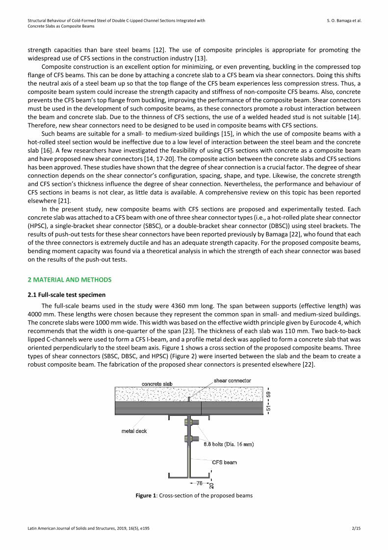
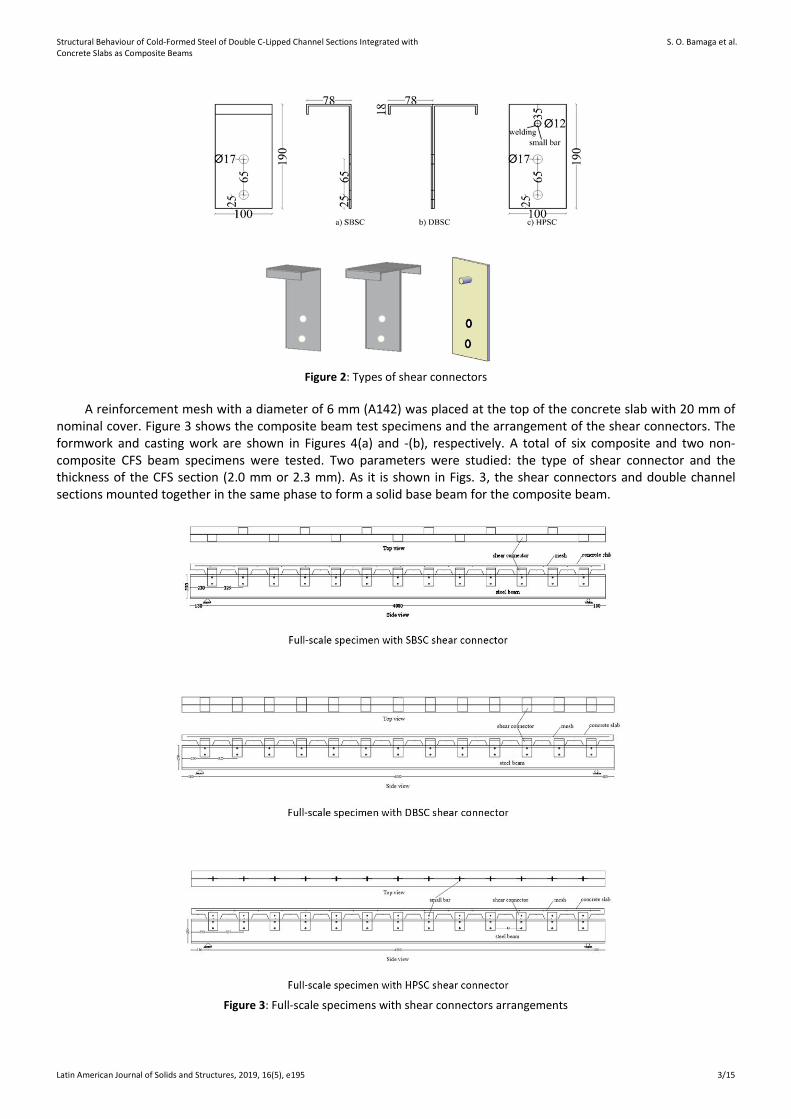
The full-scale beams used in the study were 4360 mm long. The span between supports (effective length) was 4000 mm. These lengths were chosen because they represent the common span in small- and medium-sized buildings. The concrete slabs were 1000 mm wide. This width was based on the effective width principle given by Eurocode 4, which recommends that the width is one-quarter of the span [23]. The thickness of each slab was 110 mm. Two back-to-back lipped C-channels were used to form a CFS I-beam, and a profile metal deck was applied to form a concrete slab that was oriented perpendicularly to the steel beam axis. Figure 1 shows a cross section of the proposed composite beams. Three types of shear connectors (SBSC, DBSC, and HPSC) (Figure 2) were inserted between the slab and the beam to create a robust composite beam. The fabrication of the proposed shear connectors is presented elsewhere [22].
Figure 1: Cross-section of the proposed beams
Structural Behaviour of Cold-Formed Steel of Double C-Lipped Channel Sections Integrated with Concrete Slabs as Composite Beams
S. O. Bamaga et al.
Latin American Journal of Solids and Structures, 2019, 16(5), e195 3/15
Figure 2: Types of shear connectors
A reinforcement mesh with a diameter of 6 mm (A142) was placed at the top of the concrete slab with 20 mm of nominal cover. Figure 3 shows the composite beam test specimens and the arrangement of the shear connectors. The formwork and casting work are shown in Figures 4(a) and -(b), respectively. A total of six composite and two non-composite CFS beam specimens were tested. Two parameters were studied: the type of shear connector and the thickness of the CFS section (2.0 mm or 2.3 mm). As it is shown in Figs. 3, the shear connectors and double channel sections mounted together in the same phase to form a solid base beam for the composite beam.
Figure 3: Full-scale specimens with shear connectors arrangements
Structural Behaviour of Cold-Formed Steel of Double C-Lipped Channel Sections Integrated with Concrete Slabs as Composite Beams
S. O. Bamaga et al.
Latin American Journal of Solids and Structures, 2019, 16(5), e195 4/15
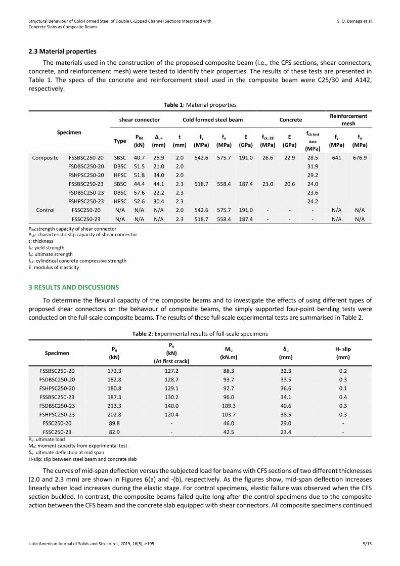
Figure 4: Preparation of full-scale specimens
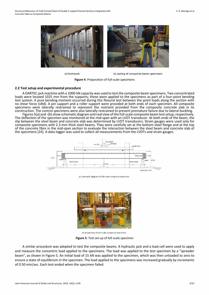
2.2 Test setup and experimental procedure A DARTEC jack machine with a 1000-kN capacity was used to test the composite beam specimens. Two concentrated
loads were located 1025 mm from the supports; these were applied to the specimens as part of a four-point bending test system. A pure bending moment occurred during this flexural test between the point loads along the section with no shear force (νRd). A pin support and a roller support were provided at both ends of each specimen. All composite specimens were laterally restrained to represent the restraint provided from the composite concrete slab in its construction. The control specimens were also laterally restrained to prevent premature failure due to lateral buckling.
Figures 5(a) and -(b) show schematic diagram and real view of the full-scale composite beam test setup, respectively. The deflection of the specimen was monitored at the mid-span with an LVDT transducer. At both ends of the beam, the slip between the steel beam and concrete slab was determined by LVDT transducers. Strain gauges were used only for composite specimens with 2.3-mm thick steel beams. They were carefully set at the bottom steel flange and at the top of the concrete fibre in the mid-span section to evaluate the interaction between the steel beam and concrete slab of the specimens [24]. A data logger was used to collect all measurements from the LVDTs and strain gauges.
Figure 5: Test set-up of full-scale specimen
A similar procedure was adopted to test the composite beams. A hydraulic jack and a load cell were used to apply and measure the concentric load applied to the specimens. The load was applied to the test specimen by a “spreader beam”, as shown in Figure 5. An initial load of 15 kN was applied to the specimen, which was then unloaded to zero to ensure a state of equilibrium in the specimen. The load applied to the specimens was increased gradually by increments of 0.50 min/sec. Each test ended when the specimen failed.
Structural Behaviour of Cold-Formed Steel of Double C-Lipped Channel Sections Integrated with Concrete Slabs as Composite Beams
S. O. Bamaga et al.
Latin American Journal of Solids and Structures, 2019, 16(5), e195 5/15
2.3 Material properties
The materials used in the construction of the proposed composite beam (i.e., the CFS sections, shear connectors, concrete, and reinforcement mesh) were tested to identify their properties. The results of these tests are presented in Table 1. The specs of the concrete and reinforcement steel used in the composite beam were C25/30 and A142, respectively.
Table 1: Material properties
Specimen
shear connector Cold formed steel beam Concrete Reinforcement mesh
Type PRd (kN)
Δuk (mm)
t (mm)
fy (MPa)
fu (MPa)
E (GPa)
fck, 28 (MPa)
E (GPa)
fck test
date (MPa)
fy (MPa)
fu (MPa)
Composite FSSBSC250-20 SBSC 40.7 25.9 2.0 542.6 575.7 191.0 26.6 22.9 28.5 641 676.9 FSDBSC250-20 DBSC 51.5 21.0 2.0 31.9 FSHPSC250-20 HPSC 51.8 34.0 2.0 29.2 FSSBSC250-23 SBSC 44.4 44.1 2.3 518.7 558.4 187.4 23.0 20.6 24.0 FSDBSC250-23 DBSC 57.6 22.2 2.3 23.6 FSHPSC250-23 HPSC 52.6 30.4 2.3 24.2
Control FSSC250-20 N/A N/A N/A 2.0 542.6 575.7 191.0 - - - N/A N/A FSSC250-23 N/A N/A N/A 2.3 518.7 558.4 187.4 - - - N/A N/A
PRd:strength capacity of shear connector Δuk: characteristic slip capacity of shear connector t: thickness fy: yield strength fu: ultimate strength fck: cylindrical concrete compressive strength E: modulus of elasticity
3 RESULTS AND DISCUSSIONS
To determine the flexural capacity of the composite beams and to investigate the effects of using different types of proposed shear connectors on the behaviour of composite beams, the simply supported four-point bending tests were conducted on the full-scale composite beams. The results of these full-scale experimental tests are summarised in Table 2.
Table 2: Experimental results of full-scale specimens
Specimen Pu
(kN)
Pu (kN)
(At first crack)
Mu (kN.m)
δu (mm)
H- slip (mm)
FSSBSC250-20 172.3 127.2 88.3 32.3 0.2 FSDBSC250-20 182.8 128.7 93.7 33.5 0.3 FSHPSC250-20 180.8 129.1 92.7 36.6 0.1 FSSBSC250-23 187.3 130.2 96.0 34.1 0.4 FSDBSC250-23 213.3 140.0 109.3 40.6 0.3 FSHPSC250-23 202.8 120.4 103.7 38.5 0.3
FSSC250-20 89.8 - 46.0 29.0 - FSSC250-23 82.9 - 42.5 23.4 -
Pu: ultimate load Mu: moment capacity from experimental test δu: ultimate deflection at mid span H-slip: slip between steel beam and concrete slab
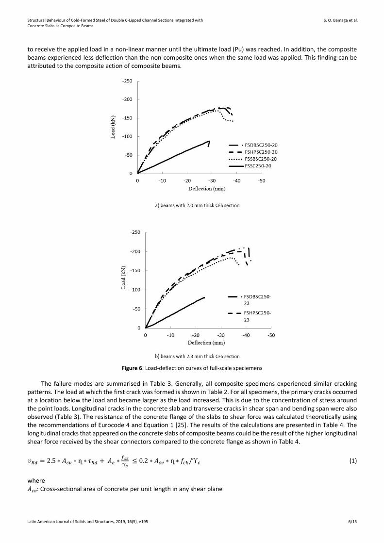
The curves of mid-span deflection versus the subjected load for beams with CFS sections of two different thicknesses (2.0 and 2.3 mm) are shown in Figures 6(a) and -(b), respectively. As the figures show, mid-span deflection increases linearly when load increases during the elastic stage. For control specimens, elastic failure was observed when the CFS section buckled. In contrast, the composite beams failed quite long after the control specimens due to the composite action between the CFS beam and the concrete slab equipped with shear connectors. All composite specimens continued
Structural Behaviour of Cold-Formed Steel of Double C-Lipped Channel Sections Integrated with Concrete Slabs as Composite Beams
S. O. Bamaga et al.
Latin American Journal of Solids and Structures, 2019, 16(5), e195 6/15
to receive the applied load in a non-linear manner until the ultimate load (Pu) was reached. In addition, the composite beams experienced less deflection than the non-composite ones when the same load was applied. This finding can be attributed to the composite action of composite beams.
Figure 6: Load-deflection curves of full-scale speciemens
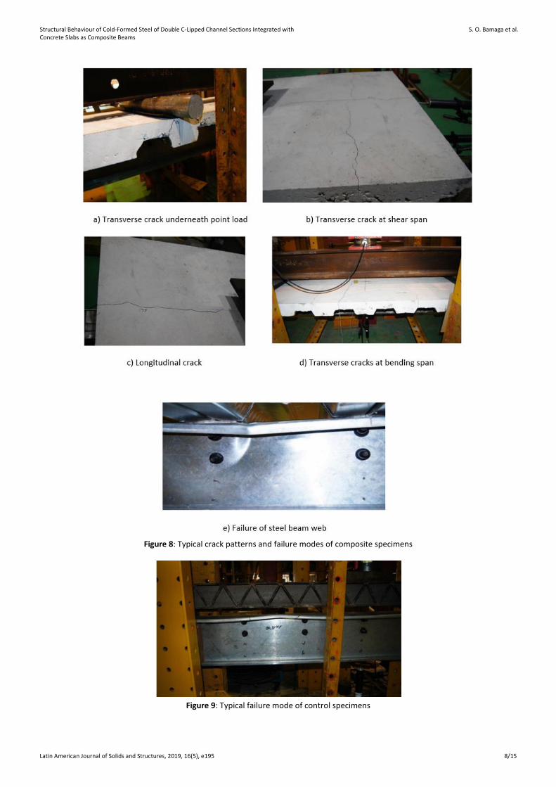
The failure modes are summarised in Table 3. Generally, all composite specimens experienced similar cracking patterns. The load at which the first crack was formed is shown in Table 2. For all specimens, the primary cracks occurred at a location below the load and became larger as the load increased. This is due to the concentration of stress around the point loads. Longitudinal cracks in the concrete slab and transverse cracks in shear span and bending span were also observed (Table 3). The resistance of the concrete flange of the slabs to shear force was calculated theoretically using the recommendations of Eurocode 4 and Equation 1 [25]. The results of the calculations are presented in Table 4. The longitudinal cracks that appeared on the concrete slabs of composite beams could be the result of the higher longitudinal shear force received by the shear connectors compared to the concrete flange as shown in Table 4.
𝑣𝑣𝑅𝑅𝑅𝑅 = 2.5 ∗ 𝐴𝐴𝑐𝑐𝑐𝑐 ∗ ɳ ∗ 𝜏𝜏𝑅𝑅𝑅𝑅 + 𝐴𝐴𝑒𝑒 ∗𝑓𝑓𝑠𝑠𝑠𝑠ϓ𝑠𝑠
≤ 0.2 ∗ 𝐴𝐴𝑐𝑐𝑐𝑐 ∗ ɳ ∗ 𝑓𝑓𝑐𝑐𝑐𝑐/ϓ𝑐𝑐 (1)
where 𝐴𝐴𝑐𝑐𝑣𝑣: Cross-sectional area of concrete per unit length in any shear plane
Structural Behaviour of Cold-Formed Steel of Double C-Lipped Channel Sections Integrated with Concrete Slabs as Composite Beams
S. O. Bamaga et al.
Latin American Journal of Solids and Structures, 2019, 16(5), e195 7/15
𝜏𝜏𝑅𝑅𝑅𝑅: Basic shear strength of concrete 𝐴𝐴𝑒𝑒: Reinforcement crossing shear plane 𝑓𝑓𝑠𝑠𝑠𝑠: Yield strength of the reinforcement ɳ: A factor taken as 1 for normal concrete ϓ𝑠𝑠, ϓ𝑐𝑐: Partial safety factor
Table 3: Failure modes of full-scale beam specimens
Specimen Concrete slab steel beam Shear connector
FSSBSC250-20 Longitudinal and transverse cracks at bending and shear
span
Web failure underneath the points load
None
FSDBSC250-20 Longitudinal and transverse cracks at bending and shear
span
Web failure underneath the points load
None
FSHPSC250-20 Longitudinal and transverse cracks at bending span only
Web failure underneath the points load
None
FSSBSC250-23 Longitudinal and transverse cracks
Web failure underneath the points load
None
FSDBSC250-23 Longitudinal and transverse cracks at bending and shear
span
Web failure underneath the points load
None
FSHPSC250-23 Longitudinal and transverse cracks at bending and shear
span
Web failure underneath the points load
None
FSSC250-20 None localized buckling at top flange underneath the points load
None
FSSC250-23 None buckling at top flange None
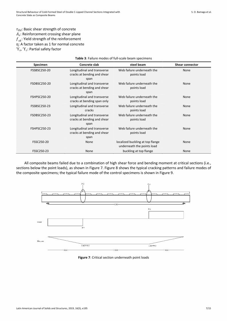
All composite beams failed due to a combination of high shear force and bending moment at critical sections (i.e., sections below the point loads), as shown in Figure 7. Figure 8 shows the typical cracking patterns and failure modes of the composite specimens; the typical failure mode of the control specimens is shown in Figure 9.
Figure 7: Critical section underneath point loads
Structural Behaviour of Cold-Formed Steel of Double C-Lipped Channel Sections Integrated with Concrete Slabs as Composite Beams
S. O. Bamaga et al.
Latin American Journal of Solids and Structures, 2019, 16(5), e195 8/15
Figure 8: Typical crack patterns and failure modes of composite specimens
Figure 9: Typical failure mode of control specimens
Structural Behaviour of Cold-Formed Steel of Double C-Lipped Channel Sections Integrated with Concrete Slabs as Composite Beams
S. O. Bamaga et al.
Latin American Journal of Solids and Structures, 2019, 16(5), e195 9/15
The deflection of the composite beam was calculated theoretically using the transformed section method. It has been stated that, for beams under service conditions, 50% of the ultimate load could be applied [26]. The effects of the partial shear connection were considered by using Equation 2. Table 4 shows the theoretical deflection values and their corresponding experimental values. The experimental deflection data were significantly better than the corresponding deflections predicted using the transformed section method. Moreover, the experiments showed improvements in deflection when compared to the limit of span/200 given by most codes of practice.
𝛿𝛿𝛿𝛿𝑐𝑐
= 1.0 + 𝐶𝐶 �1− 𝑁𝑁𝑁𝑁𝑓𝑓� ∗ �𝛿𝛿𝑎𝑎𝛿𝛿𝑐𝑐 − 1� (2)
where 𝛿𝛿𝑐𝑐: defection of the composite beam with full shear connection 𝛿𝛿𝑎𝑎: defection of the steel beam under the same loads 𝑁𝑁𝑁𝑁𝑓𝑓
: degree of shear connection
𝐶𝐶: A coefficient taken as 0.3 for un-propped construction and 0.5 for propped construction
Table 4: Comparison between theoretical and experimental deflection and longitudinal shear
Specimen 0.5*Pu
(kN) δe
(mm) δcal
(mm) νRd
(kN/m) ν
(kN/m) FSSBSC250-20 86.1 8.7 20.3 119.8 125.2 FSDBSC250-20 91.4 8.9 20.9 119.8 158.6 FSHPSC250-20 90.4 8.2 20.7 119.8 159.4 FSSBSC250-23 93.6 9.1 18.0 119.8 136.6 FSDBSC250-23 106.6 10.7 19.4 119.8 177.3 FSHPSC250-23 101.4 8.9 18.9 119.8 161.7
δe: deflection at load of 0.5*Pu δcal: calculated deflection based on transformed section method νRd: shear resistance of concrete flnage of slab ν: longituidinal shear force
Composite beam specimens exhibited much greater ultimate moment capacity than non-composite CFS beam specimens (see Figures 5(a)(b) and Table 2). The ultimate moment capacity of composite beams with a 2.0-mm thick CFS section was 100% greater than that of 2.0-mm thick non-composite beam specimens. Composite beams with CFS sections that were 2.3 mm thick exhibited an average ultimate moment capacity that was 142% greater than the ultimate moment capacity of non-composite specimens of the same thickness. During the linear loading stage, composite construction improved the stiffness of CFS beams by at least 270% for beams with 2.0-mm thick CFS sections and 259% for beams with 2.3-mm thick CFS sections (see Figures 5(a) and -(b)).
The researchers investigated the effects of the proposed shear connectors (i.e., SBSC, DBSC, and HPSC) on the strength and behaviour of composite beam specimens. Specimens with DBSC shear connectors sustained a greater ultimate moment capacity with increases of up to 13.9% when compared to specimens with SBSC shear connectors and 5.4% when compared to specimens with HPSC shear connectors (see Figures 5(a) and –(b) and Table 2). This is because a DBSC shear connector possesses a higher design strength capacity than HPSC or SBSC shear connectors (see Table 1). All composite specimens displayed similar stiffness traits during linear stage loading, as presented in Figures 5(a) and -(b). However, as load increased, the stiffness of specimens with SBSC shear connectors dropped below that of the other specimens, perhaps owing to their lower strength capacity.
Table 2 shows the ultimate moment capacities that were experimentally obtained for composite beam specimens with CFS sections of two different thicknesses (i.e., 2.0 and 2.3 mm). As expected, an increase in the thickness of the CFS section enhanced the composite beams’ ultimate moment capacity. For example, specimens with DBSC shear connectors and 2.3-mm thick CFS sections had an ultimate moment capacity that was 16.7% greater than specimens with DBSC shear connectors and 2.0-mm thick CFS sections. Similar findings were observed for specimens with HPSC and SBSC shear connectors. These findings coincide with results obtained by other researchers [10, 18].
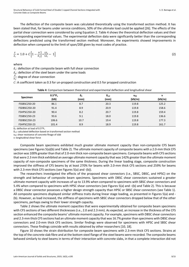
Figure 10 shows the strain distribution for composite beam specimens with 2.3-mm thick CFS sections. Strains at the top of the concrete slab fibre and at the bottom steel flange of the steel beams were recorded. The composite beams behaved similarly to steel beams in terms of their interaction with concrete slabs, in that a complete interaction did not
Structural Behaviour of Cold-Formed Steel of Double C-Lipped Channel Sections Integrated with Concrete Slabs as Composite Beams
S. O. Bamaga et al.
Latin American Journal of Solids and Structures, 2019, 16(5), e195 10/15
take place. Such incomplete interactions could be the result of significant differences between the fibre strains at any given load level. Also, the relatively great bottom steel and concrete slab fibre strains in FSSBSC250-23 specimens indicate a greater reduction in the interaction between the concrete slab and steel beam. The development of cracks could be the cause of strain reversal during the advance loading stage near the ultimate load.
Figure 10: Strain distribution
4 COMPARISON OF EXPERIMENTAL AND THEORETICAL RESULTS
The degrees of shear connection of all the specimens observed in the present study are given in Table 5. The value of this parameter is below the Eurocode 4 limit (K<0.40) for all the specimens. However, it has been reported that if the shear connectors have a larger deformation capacity, a lower degree of shear connection can be used in composite beams [27, 28]. In this study, the proposed shear connectors possess very large deformation capacities (see Table 1). Hence, the predicted ultimate moment capacities of full-scale composite beam specimens were calculated using the plastic theory principle. Due to the thinness of the CFS sections used in this study, the composite beam specimens were
Structural Behaviour of Cold-Formed Steel of Double C-Lipped Channel Sections Integrated with Concrete Slabs as Composite Beams
S. O. Bamaga et al.
Latin American Journal of Solids and Structures, 2019, 16(5), e195 11/15
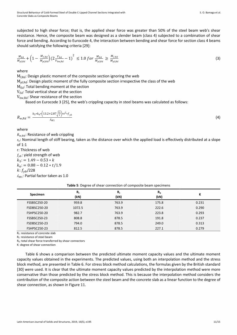
subjected to high shear force; that is, the applied shear force was greater than 50% of the steel beam web’s shear resistance. Hence, the composite beam was designed as a slender beam (class 4) subjected to a combination of shear force and bending. According to Eurocode 4, the interaction between bending and shear force for section class 4 beams should satisfying the following criteria [29]:
𝑀𝑀𝐸𝐸𝑅𝑅𝑀𝑀𝑝𝑝𝑝𝑝,𝑅𝑅𝑅𝑅
+ �1− 𝑀𝑀𝑓𝑓,𝑅𝑅𝑅𝑅𝑀𝑀𝑝𝑝𝑝𝑝,𝑅𝑅𝑅𝑅
� (2 𝑉𝑉𝐸𝐸𝑅𝑅𝑉𝑉𝑏𝑏𝑏𝑏,𝑅𝑅𝑅𝑅
− 1)2
≤ 1.0 𝑓𝑓𝑓𝑓𝑓𝑓 𝑀𝑀𝐸𝐸𝑅𝑅𝑀𝑀𝑝𝑝𝑝𝑝,𝑅𝑅𝑅𝑅
≥ 𝑀𝑀𝑓𝑓,𝑅𝑅𝑅𝑅𝑀𝑀𝑝𝑝𝑝𝑝,𝑅𝑅𝑅𝑅
(3)
where Mf,Rd: Design plastic moment of the composite section ignoring the web Mpl,Rd: Design plastic moment of the fully composite section irrespective the class of the web MEd: Total bending moment at the section VEd: Total vertical shear at the section Vbw,Rd: Shear resistance of the section
Based on Eurocode 3 [25], the web’s crippling capacity in steel beams was calculated as follows:
𝑅𝑅𝑏𝑏,𝑅𝑅𝑅𝑅 = 𝑠𝑠5∗𝑠𝑠6∗�13.2+2.87�𝑠𝑠𝑠𝑠𝑡𝑡 �∗𝑡𝑡
2∗𝑓𝑓𝑦𝑦𝑏𝑏ʎ𝑀𝑀1
(4)
where 𝑅𝑅𝑤𝑤,𝑅𝑅𝑅𝑅: Resistance of web crippling 𝑠𝑠𝑠𝑠: Nominal length of stiff bearing, taken as the distance over which the applied load is effectively distributed at a slope of 1:1 𝑡𝑡: Thickness of web 𝑓𝑓𝑦𝑦𝑦𝑦: yield strength of web 𝑠𝑠5: = 1.49− 0.53 ∗ 𝑠𝑠 𝑠𝑠6: = 0.88− 0.12 ∗ 𝑡𝑡/1.9 𝑠𝑠: 𝑓𝑓𝑦𝑦𝑦𝑦/228 ʎ𝑀𝑀1: Partial factor taken as 1.0
Table 5: Degree of shear connection of composite beam specimens
Specimen Rc
(kN) Rs
(kN) Rq
(kN) K
FSSBSC250-20 959.8 763.9 175.8 0.231 FSDBSC250-20 1072.5 763.9 222.6 0.290 FSHPSC250-20 982.7 763.9 223.8 0.293 FSSBSC250-23 808.8 878.5 191.8 0.237 FSDBSC250-23 794.0 878.5 249.0 0.313 FSHPSC250-23 812.5 878.5 227.1 0.279
Rc: resistance of concrete slab Rs: resistance of steel beam Rq: total shear force transferred by shear connectors K: degree of shear connection
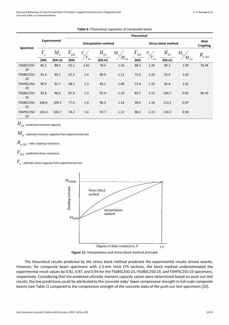
Table 6 shows a comparison between the predicted ultimate moment capacity values and the ultimate moment capacity values obtained in the experiments. The predicted values, using both an interpolation method and the stress block method, are presented in Table 6. For stress block method calculations, the formulas given by the British standard [30] were used. It is clear that the ultimate moment capacity values predicted by the interpolation method were more conservative than those predicted by the stress block method. This is because the interpolation method considers the contribution of the composite action between the steel beam and the concrete slab as a linear function to the degree of shear connection, as shown in Figure 11.
Structural Behaviour of Cold-Formed Steel of Double C-Lipped Channel Sections Integrated with Concrete Slabs as Composite Beams
S. O. Bamaga et al.
Latin American Journal of Solids and Structures, 2019, 16(5), e195 12/15
Table 6: Theoretical capacities of composite beam
Specimen
Experimental Theoretical
Interpolation method Stress block method Web Crippling
uV uM
EdV u
Ed
VV
EdM u
Ed
MM
EdV u
Ed
VV
EdM u
Ed
MM
,w RdR (kN) (kN.m) (kN) (kN.m) (kN) (kN.m)
FSSBSC250-20
86.1 88.3 61.1 1.41 76.4 1.16 68.3 1.26 85.3 1.03 76.34
FSDBSC250-20
91.4 93.7 67.2 1.4 84.0 1.11 73.6 1.24 91.9 1.02
FSHPSC250-20
90.4 92.7 68.1 1.3 85.1 1.09 73.4 1.23 91.8 1.01
FSSBSC250-23
93.6 96.0 67.0 1.3 87.4 1.10 83.7 1.12 104.7 0.92 96.10
FSDBSC250-23
106.6 109.3 77.0 1.4 96.3 1.14 90.6 1.18 113.2 0.97
FSHPSC250-23
101.4 103.7 74.2 1.4 92.7 1.12 88.2 1.15 110.2 0.94
EdM : predicted moment capacity
uM : ultimate moment capacity from experimental test
,w RdR : web crippling resistance
EdV : predicted shear resistance
uV : ultimate shear capacity from experimental test
Figure 11: Interpolation and stress block method principle
The theoretical results predicted by the stress block method predicted the experimental results almost exactly. However, for composite beam specimens with 2.3-mm thick CFS sections, the block method underestimated the experimental result values by 0.92, 0.97, and 0.94 for the FSSBSC250-23, FSDBSC250-23, and FSHPSC250-23 specimens, respectively. Considering that the predicted ultimate moment capacity values were determined based on push-out test results, the low predictions could be attributed to the concrete slabs’ lower compressive strength in full-scale composite beams (see Table 1) compared to the compressive strength of the concrete slabs of the push-out test specimens [22].
Structural Behaviour of Cold-Formed Steel of Double C-Lipped Channel Sections Integrated with Concrete Slabs as Composite Beams
S. O. Bamaga et al.
Latin American Journal of Solids and Structures, 2019, 16(5), e195 13/15
The theoretical shear (VEd) and web crippling (Rw,Rd) capacities yielded results that were conservative compared to the experimental results. This result could be attributed to the fact that the concrete slabs in composite beams contribute to vertical shear resistance [31, 32]. However, in practice, it is assumed that shear force in composite sections is resisted only by the steel beam web. Also, the theoretical results for shear and web crippling shown in Table 6 reveal that the combination of bending and shear resistance has a stronger influence on the design than web crippling does. For example, a shear force load of 68.28 kN caused the FSSBSC250-20 specimen to fail, while a load of 76.36 kN is needed for the same section to fail from web crippling.
5 CONCLUSIONS
An experimental investigation of the structural behaviour of composite beams with CFS sections was performed. A theoretical analysis was also carried out to validate the experimental results. The major contribution of this study is that it has developed efficient composite beams that can be used in the construction of medium- and small-sized buildings. This research also helps to expand the CFS industry, which, in turn, will lead to a greener and more sustainable environment. The main findings of this study can be summarized as follows:
1. The efficiency of using a composite construction concept to improve the strength and behaviour of CFS beams is clear. The new composite beams exhibited higher ultimate moment capacities and stiffness than non-composite beams.
2. The failure modes are similar for all composite beams. At shear and bending spans, transverse cracks under point loads developed first, and transverse cracks followed. Longitudinal cracks formed along the span. At the ultimate load, the beam section located underneath the point load failed from the combination of maximum bending and shear force. This result was validated by the theoretical analysis.
3. Under service conditions, deflections of the specimens were significantly improved when the test results were compared to the defection results predicted by the transformed section method.
4. The bending moment capacities of composite beam specimens are similar to the theoretical values predicted using the plastic theory principle. This result suggests that the new composite beams could be designed using the plastic theory principle.
5. Composite beam specimens with DBSC shear connectors showed a higher ultimate moment capacity than the other specimens. Also, thicker CFS sections correlated with higher strength capacities.
Acknowledgment
The work reported in this study was graciously supported by joint research under Minister of Education Malaysia and Universiti Teknologi Malaysia with Translation Research Grant Scheme Vot Nos. R.J130000.7809.4L858 and R.J130000.7309.4B235, respectively. The authors remain indebted for the support given by them.
Author’s Contributions: Conceptualization, M M Tahir and S O Bamaga; Funding acquisition, M M Tahir; Investigation, S O Bamaga; Methodology, S Mohamad, S P Ngian; Validation, A Sulaiman; Writing - review & editing, R Aghlara; Supervision, M M Tahir.
Editor: Marcílio Alves
References
[1] Bryan, E.R., (1980). European recommendations for cold-formed sheet steel in building. Fifth international specialty conference on cold-formed steel structure. 7-32 (St. Louis, Missouri, USA).
[2] Pekoz, T., (1999). Possible future developments in the design and application of cold-formed steel. Fourth international conference. Light-Weight Steel and Aluminium Structures, (Espoo, Finland).
[3] Hancock, G.J., Murray, T.M., (1996). Residential applications of cold formed structural members in australia. Thirteenth International Specialty Conference on Cold-Formed Steel Structures, 505-511 (St. Louis, Missouri, USA).
Structural Behaviour of Cold-Formed Steel of Double C-Lipped Channel Sections Integrated with Concrete Slabs as Composite Beams
S. O. Bamaga et al.
Latin American Journal of Solids and Structures, 2019, 16(5), e195 14/15
[4] Allen, D., Mid-Rise, (2006). Construction detailing issues with cold-formed steel and compatible construction materials ASCE, Structures.
[5] Ziemian, R. D., (2010). Guide to stability design criteria for metal structures. sixth ed. New Jersey: John Wiley & Sons, Inc.
[6] Köroğlu, M. A., Köken, A., Arslan, M. H., & Çevik, A. (2011). Genetic programming-based modeling of shear capacity of composite beams with profiled steel sheeting. Adv. Steel Constr., 7(2), 157-172.
[7] Köroglu, M. A., Köken, A., Arslan, M. H., & Cevik, A. (2013). Neural network prediction of the ultimate capacity of shear stud connectors on composite beams with profiled steel sheeting. Scientia Iranica. Transaction A, Civil Engineering, 20(4), 1101.
[8] Köken, A., & Köroglu, M. A. (2014). The usability of earthquake resistant steel bars as shear connectors in composite structures. Scientia Iranica. Transaction A, Civil Engineering, 21(2), 276.
[9] Barichello, C., Landesmann, A., & Camotim, D. (2017). Distortional Failure and DSM Design of Cold-Formed Steel S-Shaped Beams Under Uniform Bending. Latin American Journal of Solids and Structures, 14(12), 2123-2140.
[10] Irwan, M., Hanizah, A., Azmi, I., Koh., H., (2011). Large-scale test of symmetric cold-formed steel (CFS)–concrete composite beams with BTTST enhancement. Journal of Constructional Steel Research 67:720–726.
[11] Schafer, B.W., (2011). Cold-formed steel structures around the world. Ernst and Sohn Steel Construction 4(3):141-149.
[12] Santos, H.A.F.A., Silberschmidt, V.V., (2014). Hybrid equilibrium finite element formulation for composite beams with partial interaction. Journal of Composite Structures 108: 646-656.
[13] Irwan, M, Hanizah, A., Azmi I, Bambang, P., Koh, H, Aruan, M., (2008). Shear transfer enhancement in precast cold-formed steel-concrete composite beams: effect of bent-up tabs types and angles. Technology and Innovation for Sustainable Development Conference, (28-29 January, Thailand).
[14] Hanaor, A., (2000). Tests of composite beams with cold-formed sections. Journal of Constructional Steel Research; 54:245–264.
[15] Hossain, A., (2005). Designing thin-walled composite-filled beams. Proceedings of the Institution of Civil Engineers, Structures & Buildings 158(SB4):267-278.
[16] Johnson, R.P., (1981). Loss of interaction in short-span composite beams and plates. Journal of Constructional Steel research 1(2): 11-16.
[17] Lawson, R.M., Popo-Ola, S.O., Varley, D.N., (2001). Innovative development of light steel composite in buildings. International symposium on connections between steel and concrete 1382-1391.
[18] Lakkavalli, B., Liu, Y., (2006). Experimental study of composite cold-formed steel C-section floor joists. Journal of [1] Constructional Steel Research 62:995–1006.
[19] Fox, D.M., Schuster, R.M., (2008). Strickland m. innovative composite cold formed steel floor system. Nineteenth International Specialty Conference on Cold-Formed Steel Structures. (St. Louis, USA).
[20] Irwan, M., Hanizah, A., Azmi, I., (2009) Test of shear transfer enhancement in symmetric cold-formed steel concrete composite beams. Journal of Constructional Steel Research 65:2087-2098.
[21] Bamaga, S.O., Tahir, M. Md., Siang, T.C., Mohammad, S., Yahya, N., Saleh, A.L., Mustaffar, M., Osman, M.H., Rahman, A.B.A., (2013). Feasibility of developing composite action between concrete and cold formed steel beam. Journal of Central South University 20(12):3689-3696.
[22] Bamaga, S.O., (2013). Structural behaviour of composite beams with cold formed steel section. PhD Thesis, Universiti Teknologi Malaysia, Malaysia.
[23] EN 1994-1-1:2004 Eurocode 4. Design of composite steel and concrete structures: Part 1.1: General rules and rules for buildings. BS. British Standards Institution (London).
[24] Robinson, H., (1988). Multiple stud shear connections in deep ribbed metal deck. Canadian Journal of Civil Engineering 15(4): 553-569.
[25] Lawson, R.M., Chung, K.F., (1994). Composite beam design to Eurocode 4. Berkshire: Steel Construction Institute.
Structural Behaviour of Cold-Formed Steel of Double C-Lipped Channel Sections Integrated with Concrete Slabs as Composite Beams
S. O. Bamaga et al.
Latin American Journal of Solids and Structures, 2019, 16(5), e195 15/15
[26] Nie, J, Fan, J., Cai, C.S., (2008). Experimental study of partially shear-connected composite beams with profiled sheeting. Engineering Structures Journal 30(1):1-12
[27] Crisinel, M., (1990). Partial-interaction analysis of composite beams with profiled sheeting and non-welded shear connectors. Journal of Constructional Steel Research 15: 65-98.
[28] Bartschi, R., (2005). Load-bearing behaviour of composite beams in low degrees of partial shear connection. Ph.D Thesis, Institute of Structural Engineering, Swiss Federal Institute of Technology Zurich, Swiss.
[29] EN 1993-1-3:2006 Eurocode 3. Design of steel structures: Part 1-3: General rules: Supplementary rules for cold-formed members and sheeting. BS. British Standards Institution (London).
[30] BS5950-3-1: 1990 +A1:2010 Structural use of steelwork in building: Part 3: Design in composite Construction-Section 3.1 Code of practice for design of simple and continuous composite beams. London: British Standard Institute.
[31] Baskar, K., Shanmugam, N.E., (2003). Steel-concrete composite plate girders subject to combined shear and bending. Journal of Constructional Steel Research 59(4): 531-557.
[32] Roberts, T.M., Al-Amery, R. I.M., (1991). Shear strength of composite plate girders with web cutouts. journal of structural engineer, ASCE 117(7): 1897-1910.