STRUCTURAL AND MODAL ANALYSIS OF FLYWHEEL USED … · 233 | P a g e STRUCTURAL AND MODAL ANALYSIS...
11
233 | Page STRUCTURAL AND MODAL ANALYSIS OF FLYWHEEL USED IN PETROL ENGINE Ghanta Phaniteja 1 , Ramana Naik Banavatahu 2 1 Pursuing M.Tech, 2 Assistant Professor, Nalanda Institute of Engineering and Technology (NIET), Siddharth Nagar, Kantepudi Village, Satenepalli Mandal, Guntur Dist, AP, (India) ABSTRACT The flywheel is serves as a reservoir which stores energy in the machines through the period when the supply of energy is more than the necessity and discharges it during the period when the requirement of energy is more than supply. For instance, in I.C. engines, the energy is created just in the power stroke which is great deal more than an engine load, and no energy is being produced within the suction, compression and exhaust strokes if there should be an occurrence of four stroke engines. The additional energy is produced during power stroke is consumed by the flywheel and discharges it’s to the crank shaft amid the further strokes in which no energy is created, in this way pivoting the crankshaft at a uniform speed. The flywheel is fixed at one side of the crankshaft and fills two needs. The second, it is the mounting surface used to fasten the engine up to its heap. The point of the undertaken is to design a flywheel for a multi cylinder petrol engine flywheel using the exact equations. A parametric model of the flywheel is designed utilizing 3D modeling software CATIA V5 R18. The strengths following up on the flywheel are likewise computed. The strength of the flywheel is approved by applying the forces on the flywheel in analysis software ANSYS14.5. I. INTRODUCTION A flywheel is a heavy disk or wheel that is connected to a pivoting shaft. These are used for storage of K.E. The force of the flywheel makes it to not change its rotational speed effectively. Due to this, flywheels keep the shaft turning at the same rate of speed. This aids when the torque connected to the shaft changes frequently. Uneven torque can change the speed of turning speed. Since the flywheel opposes changes in speed, it shrinkages the impact of uneven torque. Engines which use pistons to give control more often than not have uneven torque and use flywheels to fix this issue. It takes vitality to get a wheel (any wheel) to turn. On the off chance that there is little friction then it will continue rotating quite a while. At the point when energy is required, it can be taken from the wheel once more. So it is a straightforward mechanical method for putting storing energy. The total energy stored is an element of the weight and the speed of rotation - making a heavier wheel pivot quicker takes more energy. Another variable is the span (dimension) on the grounds that the more remote from the pivot a part of the wheel is, the more energy it takes to make is rotate. These three elements can be signified by M (mass), ω (angular velocity) and R (radius). Joining the two mathematical statements below gives ω 2 MR 2 /4. A fly-wheel is any wheel, as well as particularly intended to store energy. So it ought to be overwhelming and/or pivot quickly. For example, a few transports have a fly-wheel that is utilized for halting and beginning. At the point when the transport stops (ex. Traffic signal), the fly-wheel is associated with the wheels, so the rotational energy is exchanged to it, so the
Transcript of STRUCTURAL AND MODAL ANALYSIS OF FLYWHEEL USED … · 233 | P a g e STRUCTURAL AND MODAL ANALYSIS...

233 | P a g e
STRUCTURAL AND MODAL ANALYSIS OF
FLYWHEEL USED IN PETROL ENGINE
Ghanta Phaniteja1, Ramana Naik Banavatahu
2
1Pursuing M.Tech,
2Assistant Professor, Nalanda Institute of Engineering and Technology (NIET),
Siddharth Nagar, Kantepudi Village, Satenepalli Mandal, Guntur Dist, AP, (India)
ABSTRACT
The flywheel is serves as a reservoir which stores energy in the machines through the period when the supply of
energy is more than the necessity and discharges it during the period when the requirement of energy is more
than supply. For instance, in I.C. engines, the energy is created just in the power stroke which is great deal
more than an engine load, and no energy is being produced within the suction, compression and exhaust strokes
if there should be an occurrence of four stroke engines. The additional energy is produced during power stroke
is consumed by the flywheel and discharges it’s to the crank shaft amid the further strokes in which no energy is
created, in this way pivoting the crankshaft at a uniform speed.
The flywheel is fixed at one side of the crankshaft and fills two needs. The second, it is the mounting surface
used to fasten the engine up to its heap. The point of the undertaken is to design a flywheel for a multi cylinder
petrol engine flywheel using the exact equations. A parametric model of the flywheel is designed utilizing 3D
modeling software CATIA V5 R18. The strengths following up on the flywheel are likewise computed. The
strength of the flywheel is approved by applying the forces on the flywheel in analysis software ANSYS14.5.
I. INTRODUCTION
A flywheel is a heavy disk or wheel that is connected to a pivoting shaft. These are used for storage of K.E.
The force of the flywheel makes it to not change its rotational speed effectively. Due to this, flywheels keep the
shaft turning at the same rate of speed. This aids when the torque connected to the shaft changes frequently.
Uneven torque can change the speed of turning speed. Since the flywheel opposes changes in speed, it
shrinkages the impact of uneven torque. Engines which use pistons to give control more often than not have
uneven torque and use flywheels to fix this issue.
It takes vitality to get a wheel (any wheel) to turn. On the off chance that there is little friction then it will
continue rotating quite a while. At the point when energy is required, it can be taken from the wheel once more.
So it is a straightforward mechanical method for putting storing energy. The total energy stored is an element of
the weight and the speed of rotation - making a heavier wheel pivot quicker takes more energy. Another variable
is the span (dimension) on the grounds that the more remote from the pivot a part of the wheel is, the more
energy it takes to make is rotate. These three elements can be signified by M (mass), ω (angular velocity) and R
(radius). Joining the two mathematical statements below gives ω2MR
2/4. A fly-wheel is any wheel, as well as
particularly intended to store energy. So it ought to be overwhelming and/or pivot quickly. For example, a few
transports have a fly-wheel that is utilized for halting and beginning. At the point when the transport stops (ex.
Traffic signal), the fly-wheel is associated with the wheels, so the rotational energy is exchanged to it, so the

234 | P a g e
vehicle will back off while the fly-wheel speeds up. At that point, when the vehicle needs to begin driving once
more, it is associated again and the energy is exchanged back. Obviously, you wouldn't have any desire to drag a
substantial wheel around on a vehicle, so it is made of a lighter material that can withstand extremely quick
rotation.
II. FLYWHEEL
The kinetic energy of a rotating flywheel is
E=1/2 Iω2
Where the moment of inertia of center mass is equal to
I=1/2 MR2
where I is the moment of inertia of the mass about the center of rotation and ω (omega) is the angular
velocity in radian units.
As talk over above, the flywheel does not keep up consistent speed. It essentially decreases the change of speed.
At the end of the day a flywheel controls the speed variations created by the fluctuation of the engine turning
moment amid every cycle of operation. It does not control the speed variations brought on by the changing load.
Coefficient of fluctuation of speed:
The difference between the maximum and minimum speeds during a cycle is called the maximum fluctuation of
speed. The ratio of the maximum fluctuation of speed to the mean speed is called coefficient of fluctuation of
speed.
Coefficient of steadiness:
The equal of coefficient of fluctuation of pace is called coefficient of steadiness and it is represented by letter
„m‟.

235 | P a g e
III. FINITE ELEMENT ANALYSIS (FEA)
The fundamental idea in FEA is that the body or structure may be separated into littler components of finite
measurements called “Finite Elements”. The original body or the structure is then considered as an array of
these components associated at a limited number of joints called “hubs”. Straightforward capacities are
approximated the removals over each limited component. Such accepted capacities are called “shape
capacities”. This will signify the movement within the components as far as the relocation at the hubs of the
components.
The Finite Element method is a scientific tool for resolving ordinary and partial differential comparison in light
of the fact it is a numerical tool, it can take care of the complex issue that can be signified in differential
mathematical statement from. The use of FEM is limitless as respects the arrangement of down to earth design
issues. Because of high cost of processing power of years passed by, FEM has a history of being utilized to take
care of complex and expense critical difficulties.
MATERIAL PROPERTIES OF FLYWHEEL
Material Name &
Properties
Cast Iron CFRP Beta Ti Alloy
Young‟s Modulus (E) 103000 N/mm2
80000N/mm2 72000N/mm
2
Poisson‟s Ratio 0.211 0.33 0.21
Density 0.0000071 Kg/mm3
0.00000268Kg/mm3 0.00000255Kg/mm
3
IV. STATIC AND MODAL ANALYSIS OF FLYWHEEL
Flywheel Imported Model from Catia V5 R18
Structural Analysis Of Flywheel
Meshed Model

236 | P a g e
Total Deformation
Equivalent Stress
Equivalent Elastic Strain
Modal Analysis For Cast Iron
Modal Analysis 1

237 | P a g e
Modal Analysis 2
Modal Analysis 3
Modal Analysis 4
Modal Analysis 5

238 | P a g e
Carbon Fiber Reinforced Plastic
Total Deformation
Equivalent Stress
Equivalent Elastic Strain
Modal analysis for Carbon Fiber
Modal analysis 1
239 | P a g e
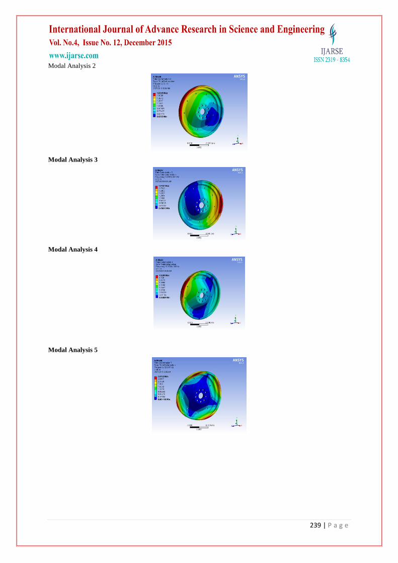
Modal Analysis 2
Modal Analysis 3
Modal Analysis 4
Modal Analysis 5
240 | P a g e
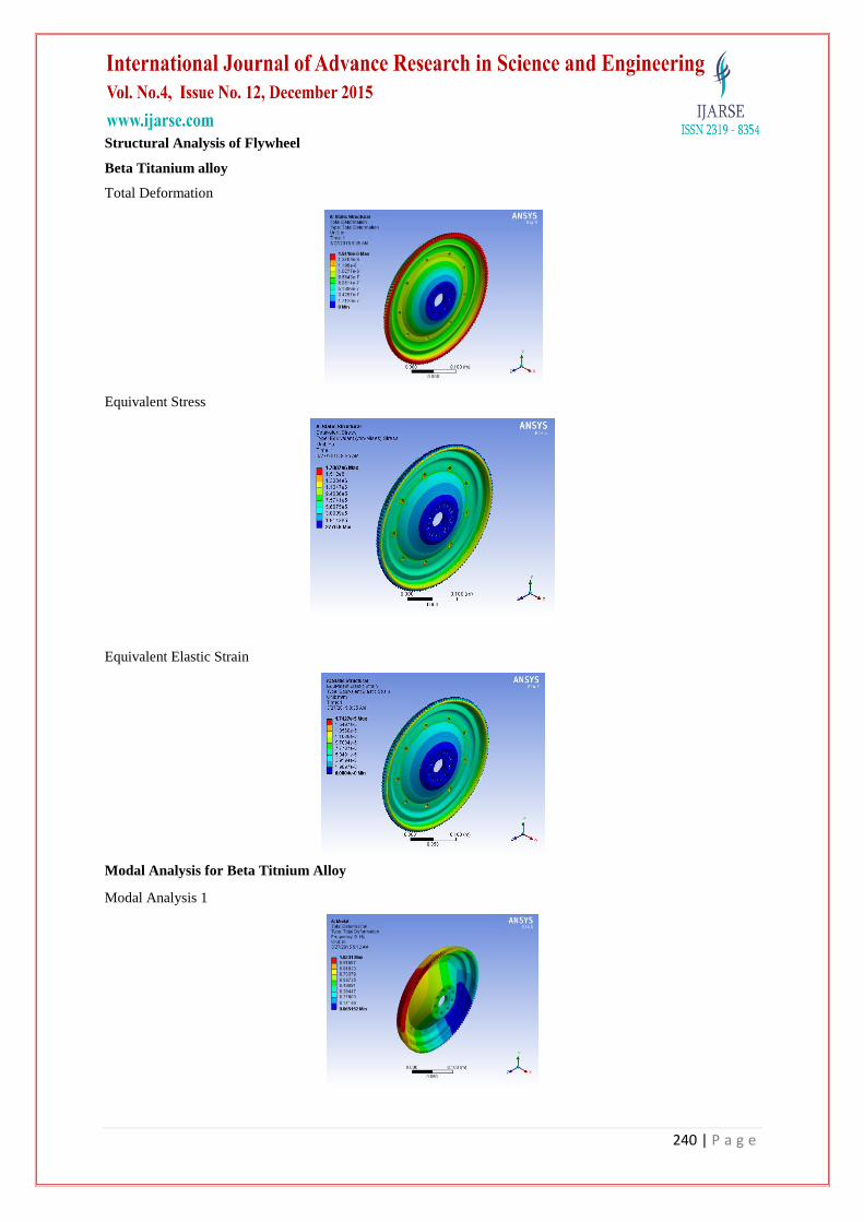
Structural Analysis of Flywheel
Beta Titanium alloy
Total Deformation
Equivalent Stress
Equivalent Elastic Strain
Modal Analysis for Beta Titnium Alloy
Modal Analysis 1

241 | P a g e
Modal Analysis 2
Modal Analysis 3
Modal Analysis 4
Modal Analysis 5

242 | P a g e
V. RESULTS AND DISCUSSION
Numerical values obtained during analysis:
si.no material Displacement von-mises stress Strain
min Max Min Max min max
1 CAST IRON 0 1.678E-6 4483.8 2.5119E6 5.8894E-8 1.919E-5
2
CARBON
FIBER 0 5.1123E-6 889.02 5.127E5 1.8677E-7 5.817E-5
3
BETA
TITANIUM 0 1.5416E-6 2776.8 1.7007E6 6.0004E-8 1.74E-5
Table 1
si.no material
mode
1 mode 2 mode 3 mode 4 mode 5
1 CAST IRON 0.81 0.83 0.59 0.76 0.97
2
CARBON
FIBER 1.5 1.63 1.91 1.9201 1.63
3
BETA
TITANIUM 1.0231 1.0073 1.059 1.1209 1.0361
Table 2
VI. CONCLUSION
In this project we have designed a flywheel used in a multi cylinder petrol engine using theoretical calculations.
2d drawing is created and modeling of flywheel is done using CATIA V5 R18. We have done structural and
modal analysis on flywheel using three materials Gray Cast Iron, Carbon fiber and Titanium alloy to validate
our design.
By seeing the results, for every one of the materials the strength values are less than their individual yield
strength values. So our design is safe. We have additionally done modal analysis for number of modes to see the
displacement of flywheel for number of frequencies. By comparing the results for three materials, the strength
value for Carbon fiber and Titanium alloy is less than that of Cast Iron.
So we conclude that for our design, Gray Cast Iron is better material for flywheel. The nodes are selected at
constrained area, pressure area and open area. In this project mainly we did material optimization.
REFERENCES
[1]. "Flywheels move from steam age technology to Formula 1"; Jon Stewart | 1 July 2012, retrieved 2012-
07-03
[2]. Jump up^ [2], "Breakthrough in Ricardo Kinergy „second generation‟ high-speed flywheel technology";
Press release date: 22 August 2011. retrieved 2012-07-03
[3]. Janse van Rensburg, P.J. "Energy storage in composite flywheel rotors". University of Stellenbosch.
[4]. Jump up^ rosseta Technik GmbH, Flywheel Energy Storage, German, retrieved February 4, 2010.
[5]. Zhang Da-lun, Mechanics of Materials, Tongji University Press, Shjanghai, 1993

243 | P a g e
[6]. Huang Xi-kai, Machine Design, Higher Education Press, Beijing, 1995
[7]. Robert L. Norton, Design of Machinery, McGraw-Hill Inc, New York, 1992
[8]. K. Lingaiah, Machine Design Data Handbook, McGraw-Hill Inc, New York, 1994
[9]. R. S. Khurmi, J. K. Gupta, Machine Design, Eurasia Publishing House, NewDelhi, 1993
[10]. ANSYS User's Manual, Swanson Analysis Systems, Inc., Houston
AUTHOR DETAILS
G.Phaniteja, pursuing M.Tech (CAD/CAM) from Nalanda Institute of Engineering and
Technology(NIET), Siddharth Nagar, Kantepudi village, Satenepalli Mandal, Guntur
dist, AP, INDIA.
Ramana Naik Banavatahu, working as Assistant Professor (CAD/CAM) from Nalanda
Institute of Engineering and Technology(NIET), Siddharth Nagar, Kantepudi village,
Satenepalli mandal, Guntur dist, AP, INDIA.