Structural and Material Analysis of an Automobile Wheel ...
6
International Research Journal of Engineering and Technology (IRJET) e-ISSN: 2395-0056 Volume: 06 Issue: 12 | Dec 2019 www.irjet.net p-ISSN: 2395-0072 © 2019, IRJET | Impact Factor value: 7.34 | ISO 9001:2008 Certified Journal | Page 999 Structural and Material Analysis of an Automobile Wheel Rim using ANSYS Sudhakar Mishra 1 , Dr. L.P. Singh 2 1 M. Tech Student, Thermal Engg. (Mechanical Engineering Dept.), SHUATS, Prayagraj, India 2 Associate Professor (Mechanical Engineering Dept.), SHUATS, Prayagraj, India ---------------------------------------------------------------------***---------------------------------------------------------------------- Abstract - A rim model was made with Solidworks 2018 software. Load analysis was performed based on the input data in ANSYS software. The results obtained after performing the analysis shows the difference in the structural behaviour of the rim model. A standard rim size according to SAE of 17 inch is taken and analysed. For analysis, ANSYS WORKBENCH 19.2 software is used. Fixed support is applied on the 5 lug holes. Pressure of 0.34474 MPa (50 psi) is applied on the outer surface (wheel barrel). Meshing is performed, then materials are applied. For the ease of work, four different ANSYS workbench files were created with different materials. Parameters of fixed support and pressure were applied on the model with different materials (Steel, Aluminum alloy, Titanium alloy, Magnesium alloy). Key Words: Alloy wheel, wheel rim, SOLIDWORKS, ANSYS Workbench, stress analysis, deformation analysis. 1. DEFINITION OF WHEEL A wheel is a circular block of a hard and durable material at whose center has been bored a circular hole through which is placed an axle bearing about which the wheel rotates when a moment is applied by gravity or torque to the wheel about its axis, thereby making together one of the six simple machines. When placed vertically under a load-bearing platform or case, the wheel turning on the horizontal axle makes it possible to transport heavy loads. Alloy wheel rims are automobile wheels which are made from an alloy of aluminum or magnesium metals or sometimes a mixture of both. Difference between Alloy wheels rim and normal steel wheel rim is due to their low weight, which improves the routing and the velocity of the car. 1.1 Requirements and Functions of a wheel: The various requirements of an automobile wheel are: 1. It must be strong enough to perform the above functions. 2. It should be balanced both statically as well as dynamically. 3. It should be as light as possible so that the unsprung weight is least. 4. It should be possible to remove or mount the wheel easily. 5. Its material should not deteriorate with weathering and age. In case the material is susceptible to corrosion, it must be given suitable protective treatment. The following are the main functions of a wheel rim: 1. Transferring torque (braking and acceleration) 2. Support mass (support the mass of the motor vehicle) 3. Adds mass (damped mass for diving comfort) 4. Dissipating heat (due to braking) 5. Absorb Impact (road hazard) 6. Conserve Energy (potential energy in momentum) 2. METHODOLOGY: The following parameters were considered during modeling of the Wheel listed in table 1. A standard rim size according to SAE of 17 inch is taken and analysed as shown in figure 1. The wheel has 5 major spokes which are split in two parts. Table -1: Parameters of model of the wheel rim. Parameter Value Diameter of rim 431.80 mm Width of rim 185.42 mm Bolt hole diameter 16 mm Hub diameter 63.50 mm Fig.1. Dimension sketch of the rim model used for analysis.
Transcript of Structural and Material Analysis of an Automobile Wheel ...

International Research Journal of Engineering and Technology (IRJET) e-ISSN: 2395-0056
Volume: 06 Issue: 12 | Dec 2019 www.irjet.net p-ISSN: 2395-0072
© 2019, IRJET | Impact Factor value: 7.34 | ISO 9001:2008 Certified Journal | Page 999
Structural and Material Analysis of an Automobile Wheel Rim using
ANSYS
Sudhakar Mishra1, Dr. L.P. Singh2
1M. Tech Student, Thermal Engg. (Mechanical Engineering Dept.), SHUATS, Prayagraj, India 2Associate Professor (Mechanical Engineering Dept.), SHUATS, Prayagraj, India
---------------------------------------------------------------------***----------------------------------------------------------------------Abstract - A rim model was made with Solidworks 2018 software. Load analysis was performed based on the input data in ANSYS software. The results obtained after performing the analysis shows the difference in the structural behaviour of the rim model. A standard rim size according to SAE of 17 inch is taken and analysed. For analysis, ANSYS WORKBENCH 19.2 software is used. Fixed support is applied on the 5 lug holes. Pressure of 0.34474 MPa (50 psi) is applied on the outer surface (wheel barrel). Meshing is performed, then materials are applied. For the ease of work, four different ANSYS workbench files were created with different materials. Parameters of fixed support and pressure were applied on the model with different materials (Steel, Aluminum alloy, Titanium alloy, Magnesium alloy).
Key Words: Alloy wheel, wheel rim, SOLIDWORKS, ANSYS Workbench, stress analysis, deformation analysis.
1. DEFINITION OF WHEEL
A wheel is a circular block of a hard and durable material at whose center has been bored a circular hole through which is placed an axle bearing about which the wheel rotates when a moment is applied by gravity or torque to the wheel about its axis, thereby making together one of the six simple machines. When placed vertically under a load-bearing platform or case, the wheel turning on the horizontal axle makes it possible to transport heavy loads. Alloy wheel rims are automobile wheels which are made from an alloy of aluminum or magnesium metals or sometimes a mixture of both. Difference between Alloy wheels rim and normal steel wheel rim is due to their low weight, which improves the routing and the velocity of the car.
1.1 Requirements and Functions of a wheel:
The various requirements of an automobile wheel are:
1. It must be strong enough to perform the above functions.
2. It should be balanced both statically as well as dynamically.
3. It should be as light as possible so that the unsprung weight is least.
4. It should be possible to remove or mount the wheel easily.
5. Its material should not deteriorate with weathering and age. In case the material is susceptible to corrosion, it must be given suitable protective treatment.
The following are the main functions of a wheel rim:
1. Transferring torque (braking and acceleration)
2. Support mass (support the mass of the motor vehicle)
3. Adds mass (damped mass for diving comfort)
4. Dissipating heat (due to braking)
5. Absorb Impact (road hazard)
6. Conserve Energy (potential energy in momentum)
2. METHODOLOGY: The following parameters were considered during modeling of the Wheel listed in table 1. A standard rim size according to SAE of 17 inch is taken and analysed as shown in figure 1. The wheel has 5 major spokes which are split in two parts.
Table -1: Parameters of model of the wheel rim.
Parameter Value
Diameter of rim 431.80 mm
Width of rim 185.42 mm
Bolt hole diameter 16 mm
Hub diameter 63.50 mm
Fig.1. Dimension sketch of the rim model used for analysis.

International Research Journal of Engineering and Technology (IRJET) e-ISSN: 2395-0056
Volume: 06 Issue: 12 | Dec 2019 www.irjet.net p-ISSN: 2395-0072
© 2019, IRJET | Impact Factor value: 7.34 | ISO 9001:2008 Certified Journal | Page 1000
A 3D model of the wheel rim is made in SolidWorks software. The isometric view of the model is shown in figure 2:
Fig.2. Final extruded Isometric view of the wheel rim.
Fig.3. Meshing of the model in ANSYS.
Fig.4. Applying fixed support to the model.
Fig.5. Pressure on the surface of the model.
Fig.6. Total Deformation with steel material.
Fig.7. Equivalent Elastic Strain with steel material.
Fig.8. Equivalent sress with steel material.
International Research Journal of Engineering and Technology (IRJET) e-ISSN: 2395-0056
Volume: 06 Issue: 12 | Dec 2019 www.irjet.net p-ISSN: 2395-0072
© 2019, IRJET | Impact Factor value: 7.34 | ISO 9001:2008 Certified Journal | Page 1001
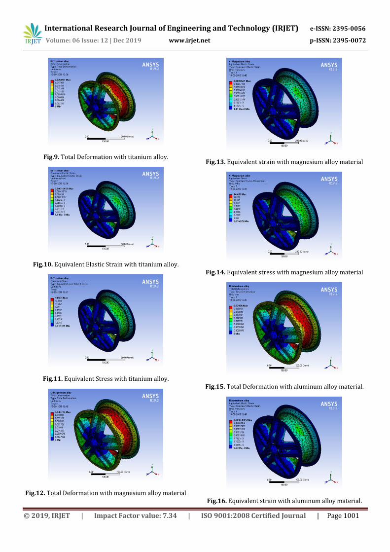
Fig.9. Total Deformation with titanium alloy.
Fig.10. Equivalent Elastic Strain with titanium alloy.
Fig.11. Equivalent Stress with titanium alloy.
Fig.12. Total Deformation with magnesium alloy material
Fig.13. Equivalent strain with magnesium alloy material
Fig.14. Equivalent stress with magnesium alloy material
Fig.15. Total Deformation with aluminum alloy material.
Fig.16. Equivalent strain with aluminum alloy material.
International Research Journal of Engineering and Technology (IRJET) e-ISSN: 2395-0056
Volume: 06 Issue: 12 | Dec 2019 www.irjet.net p-ISSN: 2395-0072
© 2019, IRJET | Impact Factor value: 7.34 | ISO 9001:2008 Certified Journal | Page 1002
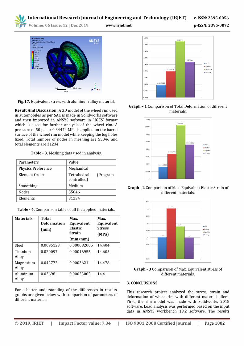
Fig.17. Equivalent stress with aluminum alloy material.
Result And Discussion: A 3D model of the wheel rim used in automobiles as per SAE is made in Solidworks software and then imported in ANSYS software in ‘.IGES’ format which is used for further analysis of the wheel rim. A pressure of 50 psi or 0.34474 MPa is applied on the barrel surface of the wheel rim model while keeping the lug holes fixed. Total number of nodes in meshing are 55046 and total elements are 31234.
Table - 3. Meshing data used in analysis.
Parameters Value
Physics Preference Mechanical
Element Order Tetrahedral (Program controlled)
Smoothing Medium
Nodes 55046
Elements 31234
Table - 4. Comparison table of all the applied materials.
Materials Total Deformation
(mm)
Max. Equivalent Elastic Strain
(mm/mm)
Max. Equivalent Stress
(MPa)
Steel 0.0095123 0.000082005 14.404
Titanium Alloy
0.020097 0.00016955 14.605
Magnesium Alloy
0.042772 0.0003621 14.478
Aluminum Alloy
0.02698 0.00023005 14.4
For a better understanding of the differences in results, graphs are given below with comparison of parameters of different materials:
Graph – 1 Comparison of Total Deformation of different materials.
Graph - 2 Comparison of Max. Equivalent Elastic Strain of different materials.
Graph - 3 Comparison of Max. Equivalent stress of different materials.
3. CONCLUSIONS
This research project analyzed the stress, strain and deformation of wheel rim with different material offers. First, the rim model was made with Solidworks 2018 software. Load analysis was performed based on the input data in ANSYS workbench 19.2 software. The results
International Research Journal of Engineering and Technology (IRJET) e-ISSN: 2395-0056
Volume: 06 Issue: 12 | Dec 2019 www.irjet.net p-ISSN: 2395-0072
© 2019, IRJET | Impact Factor value: 7.34 | ISO 9001:2008 Certified Journal | Page 1003
obtained after performing the analysis shows the difference in the structural behavior of the rim model.
It is concluded that structural steel shows least strain and deformation on same static load condition. But due to its heavy weight it causes load on the performance of engine, and should be least considered. The lower deformation and strain level of steel shows that is can be considered for heavy loads such as in heavy vehicles such as truck, bus, railways, etc. or can be used in off-roading vehicles. Yet it is the cheapest of all materials which makes it highly commercial.
Although, the second best results come for Titanium alloy considering the lightest in weight among all other materials but it has more stress generation compared to all other materials used in this analysis. Titanium is known for its high demand and use in aerospace industry as it is light weight, and will be very efficient for vehicles in fuel consumption. But its high cost makes it non-commercial.
Magnesium alloy is also a very good and light weight material, it is highly resistant to corrosion and made its way to certain gadgets such as camera, mobile phones, laptops, etc. but as it can be seen from this analysis it has higher deformation and strain level so it is not found considerable. Also it is not cost efficient as it costs near to titanium alloy.
The generally used aluminum alloys are light weight and cost efficient due to their large market and higher production. Aluminum is available in abundance in earth, it is comparably easier to extract from its more than titanium and shows great properties in terms of its formability and machinability. So it is a favorable material for both the manufacturers and consumers.
Hence, titanium alloy is better suitable material if cost is no issue; otherwise Aluminum Alloy among these four materials is good for wheel rim obtained from this research analysis.
Scope for Future Work: Due to limitations of computer processing hardware, a very high setting of mesh could not be obtained. Also, because of the same reason explicit dynamic analysis could not be performed which could have shown a more close real to life analysis of the wheel rim. So, for future work, a higher mesh setting can be applied for analysis and explicit dynamic analysis can be performed.
REFERENCES
[1] Bastin Bimal, S Adars , Madhu Akshay, Krishnan Arun, Jose Betson, Raj Praveen (2017), Finite Element Analysis of Wheel Rim Using Abaqus Software, International Journal of Engineering Research and Application, Volume 7 Issue 2 pp 31 - 34.
[2] Batli Manjunath, Manazir Mohammad, Chitresh N, Malatesh (2016), Finite Element Analysis on two Wheeler Alloy Wheel, International Journal of Research in Engineering and Science (IJRES), Volume 4 Issue 10 pp 72 - 79.
[3] Bhattacharjya Angel, Jadhav P.V, Jadhav D.B (2018), Finite Element Analysis Of Wheel Rim For Cornering And Radial Load Condition, Journal of Emerging Technologies and Innovative Research (JETIR), Volume 5 Issue 6 pp 461 - 466.
[4] Chandrashekhar E, Rishi J. P (2015), Modeling and Analysis of Automotive Wheel Rim using FEM, International Journal of Innovative Research in Technology (IJIRT), Volume 3 Issue 4 pp 24 - 32.
[5] Choudhary V Sathrudhan, et.al. (2016), Design and Analysis of wheel rim with Magnesium alloys (ZK60A) by using Solidworks and finite element method, International Journal of Innovations in Engineering Research and Technology (IJIERT), Volume 3 Issue 5 pp 16 - 19.
[6] Dascal Amalia Ana, Carauleanu Daniel (2011), Wheels Auto Modeling Using Finite Element Method, Annals of Faculty Engineering Hunedoara – International Journal of Engineering, pp 199 - 202.
[7] Gondhali Suraj L, Banubakode Milind M, Biradar Ankush K (2017), Structural Simulation of Car Rim Using Finite Element Method, International Research Journal of Engineering and Technology (IRJET), Volume: 04 Issue: 07 pp 323- 326.
[8] Hebbal M. S, Dabair Mukunda (2019), Static Structural, Modal and Harmonic Analysis of Alloy Car Wheel Rim using ANSYS Workbench, International Journal of Engineering Research & Technology (IJERT), Volume 8 Issue 7 pp 599 - 611.
[9] Hussain Katika Khaja, Ramudu M Venkata, Hussain P and Babu S Sudhakar (2017), Design Validation and Buckling Analysis of Aluminum alloy wheel for straight and slant spokes, International Journal of Mechanical Engineering Research and Technology (IJMERT), Volume 3 Issue 3 pp 80 - 92.
[10] Jape Rahul K, Jadhav S. G (2016), CAD Modeling and FEA Analysis of Wheel Rim for Weight Reduction, International Journal of Engineering Science and Computing (IJESC), Volume 6 Issue 6 pp 7404 - 7411.
[11] Kancheti Naveen, Vemula Atchi Reddy, Gudibandla Gopi Reddy, Krishna Hetesh, Subramanyam P N V Bala (2019), Modeling and Analysis of Wheel Rim Using Ansys, International Journal of Innovative Technology and Exploring Engineering (IJITEE), Volume 8 Issue 8 pp 415 - 418.

International Research Journal of Engineering and Technology (IRJET) e-ISSN: 2395-0056
Volume: 06 Issue: 12 | Dec 2019 www.irjet.net p-ISSN: 2395-0072
© 2019, IRJET | Impact Factor value: 7.34 | ISO 9001:2008 Certified Journal | Page 1004
[12] Kumar Manoj C, Sireesha S C (2018), Design and Performance Analysis of Multiple Spokes of Car Alloy Wheels, International Journal of Research in Advent Technology (IJRAT), Special Issue pp 219 - 226.
[13] Kumar V. Dharani, et al. (2014), Review on Fatigue Analysis of Aluminum Alloy Wheel under Radial Load for Passenger Car, International Journal of Engineering Development and Research (IJEDR), Volume 3 Issue 1 pp 121 - 125.
[14] Mandage A. P, Sharma M. H, Rayate A. K, Kange P. N, Hirulkar N. S (2016), Fatigue Life Estimation of An Aluminium Wheel Rim Using Finite Element Analysis, International Journal for Science & Advance Research in Technology (IJSART), Volume 2 Issue 3 pp 30 - 33.
[15] Meghashyam P, Naidu S. Girivardhan and Baba N. Sayed (2013), Design and Analysis of Wheel Rim using CATIA & ANSYS, International Journal of Application or Innovation in Engineering & Management (IJAIEM), Volume 2 Issue 8 pp 14 - 20
[16] Radha K. Kalyani, Kumar G Srinivas and Babu J Paul Rufus (2015), European Journal of Advances in Engineering and Technology, European Journal of Advances in Engineering and Technology (EJAET), Volume 2 Issue 3 pp 1 - 6.
[17] Rao K. Srinivasa, Rajesh M, Babu G. Sreedhara (2017), Design And Analysis Of Alloy Wheels, International Research Journal of Engineering and Technology (IRJET), Volume 4 Issue 6 pp 2036 - 2042.
[18] Rao K. Venkateswara and Dharmaraju T (2014), Analysis of Wheel Rim Using Finite Element Method, International Journal of Engineering Research & Technology (IJERT), Volume 3 Issue 1 pp 1259 - 1263.
[19] Ravichandra M, Babu S. Ramesh Kumar, Salmon A, Nagaraju P (2015), Design and Structural Analysis of Alloy Wheels for Light Weight Vehicles, IOSR Journal of Mechanical and Civil Engineering (IOSR-JMCE), Volume 12 Issue 6 pp 73 - 82.
[20] Sureddi Chaitanya (2018), Design, Material Optimization and Dynamic Analysis on Automobile Wheel Rim, International Journal of Scientific and Research Publications (IJSRP), Volume 8 Issue 11 pp 486 - 509.
[21]Tadesse Gamachisa Mitiku (2017), Modeling and Analysis of Car Wheel, International Research Journal of Engineering and Technology (IRJET), Volume: 04 Issue: 02 pp 395 - 402.
[22] Thakare Rakesh B, Badgujar Tushar Y (2016), Review Of Finite Element Analysis Of Vehicle Rim, International Journal of Advance Research in Science and Engineering (IJARSE), Volume 5 Issue 2 pp 466 - 471.
[23] Ullagaddi Praveen S, Sangangouda P, Chandankumar J, Dayanand H, Karthik A.S (2016), Static Analysis of Alloy Wheel Using FEA, International Journal for Research in Applied Science & Engineering Technology (IJRASET), Volume 4 Issue 8 pp 18 - 23.
[24] Undru Sriraj, Reddy P. Prabhakar (2017), Design and Analysis of Aluminum Alloy Wheel, International Journal of Engineering Research and Application (IJERA), Volume 7 Issue 3 pp 57 - 65.
[25] Valetava Karan, jethava Param (2016), Fatigue and Static Structural Analysis of Car Wheel using Finite Element Method, International Journal of Technical Innovation In Modern Engineering & Sciences, Volume 2 Issue 2 pp 19 - 28.
[26] Venkatesh K, Manjunatha Babu. N. S, Mohan Kumar K (2017), Linear Static Analysis Of A Car Alloy Wheel Design Using Finite Element Analysis, International Journal Of Engineering Sciences & Research Technology (IJESRT), Volume 6 Issue 1 pp 197 - 203.