Structural and Geotechnical Issues Impacting The Dalles ...
26
Structural and Geotechnical Issues Impacting The Dalles Spillwall Construction and Bay 1 Erosion Repair Jeffrey M. Ament, PE U.S. Army Corps of Engineers, Portland District (503) 808-4950 [email protected]
Transcript of Structural and Geotechnical Issues Impacting The Dalles ...

Structural and GeotechnicalIssues Impacting The Dalles
Spillwall Construction and Bay 1Erosion Repair
Jeffrey M. Ament, PEU.S. Army Corps of Engineers,Portland District(503) [email protected]

Reason for the Spillwall
• Juvenile Fish Passagethrough spillway
• Predator habitat to theSouth
• Spill only in northern bays• Lateral flow and retention
time not acceptable• Need to separate spilling
bays from non-spillingbays with a training wall

Spillwall Requirements• Wall width: must match existing 10’ Pier width• Wall height: 43’• Wall length: 193’

Structural Design
• Load– Design load occurred
at a River flow of 1050kcfs and assumed spillon only one side
• Overturn Moment –1083.6 ft-kips/ft of wall
• Shear – 62.1 kips/ft ofwall

Typical Existing Wall
• Foundation belowstilling basin slab
• Design would be verydifficult to add to theexisting structure

Construction Method• Construct Wall first
– Tremie placed concrete
• Construct Foundation last– Post-tension wall to rock
using rock bolts
• Requires 3 rock boltsevenly spaced across thewidth (2.5’ o.c.) every 3’o.c. the entire length
• Each rock bolt post-tensioned to 545 kips

Construction
• In-Water Work Period– Minimal Fish in the
River System– November 1, 2003 –
February 28, 2004

Underwater (Tremie) PlacedConcrete

Rock Bolt Ducts• Spiral wound steel
ducts, used inprestressed concreteindustry, specified asoption for contractor
• Difficult to holdalignment duringconcrete placements
• Lesson learned: not agood choice fordrilling through

Concrete Formwork

Cap Placement

Completed Spillwall

Spillwall in Action

New Spill Pattern

Bay 1 Erosion Hole Repair

Bay 1 Stilling Basin Erosion HoleRepair
• 4’ Deep Hole in 5’ Stilling Basin Slab
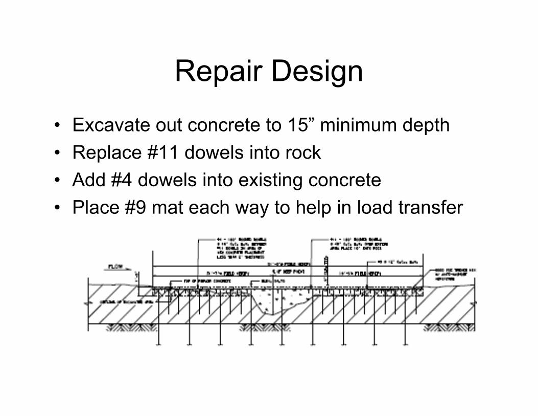
Repair Design
• Excavate out concrete to 15” minimum depth• Replace #11 dowels into rock• Add #4 dowels into existing concrete• Place #9 mat each way to help in load transfer

Contractor Chose to Dewater
• Very difficult todewater
• Water coming in from:– Wall joints– Floor joints, Floor slab
drains pressurizedwith tailwater
– Contractor TemporaryBulkhead
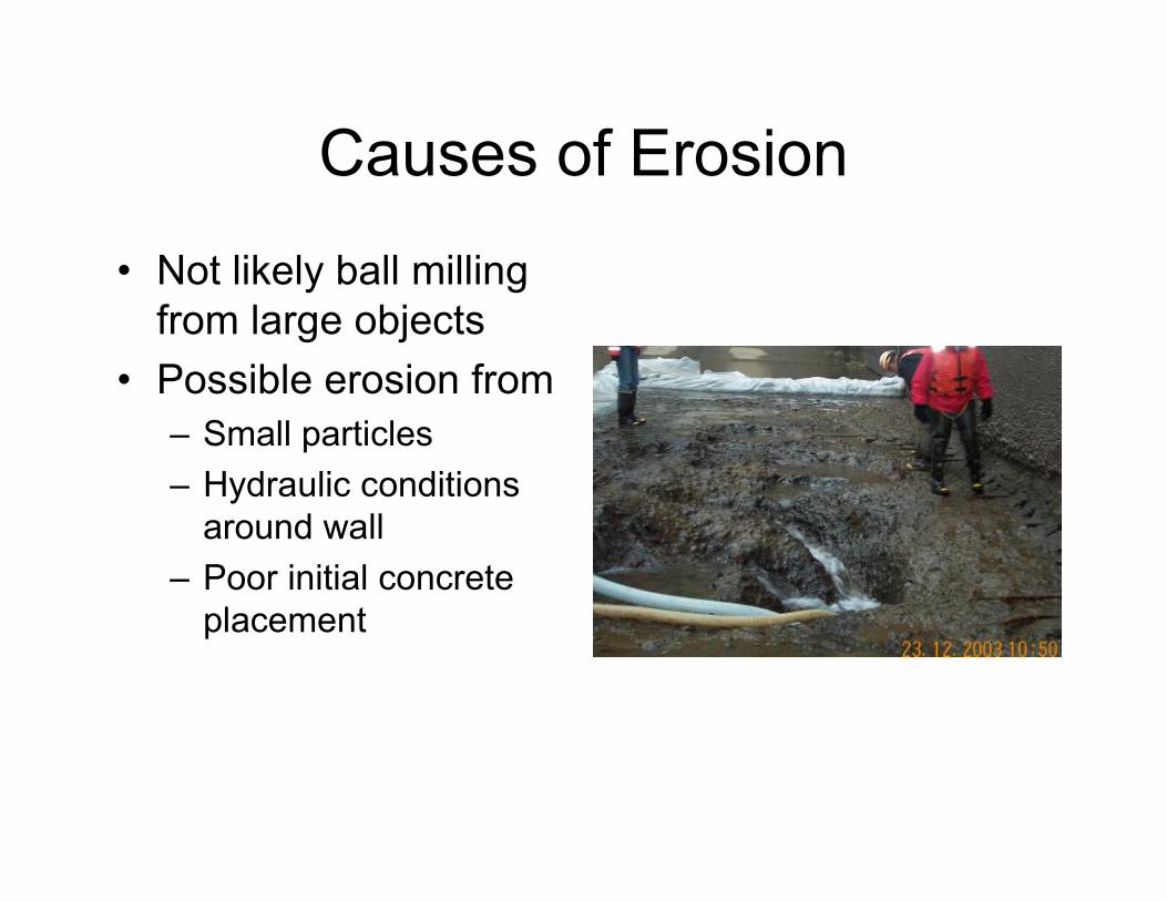
Causes of Erosion
• Not likely ball millingfrom large objects
• Possible erosion from– Small particles– Hydraulic conditions
around wall– Poor initial concrete
placement

Dowels into Rock• Holes drilled into rock
giving water• Grout socks used to
enable placement ofdowels – providingmechanical anchorage
• Dowels still gave water• Average dowel tested –
withstood ~10 kips beforehook bent and testsuspended, dowelsdeclared acceptable

Dowels into Concrete• Some holes penetrated
slab and geysered• Switched from
cementious grout toepoxy grout to shortenembedment length
• Geysering holes cappedwith PVC pipe to divertwater out of concreteplacement area

Concrete Placement Plan
• Due to dewatering problems– Flood bay to within 1’-3’ of tailwater (to keep
bulkhead from blowing off)– Build a 4”-high form around placement area to
account for poor surface concrete– Tremie place concrete using antiwash-out
admix using direct pump method directed bydiver
– Cure for 1 week underwater, then dewaterand remove excess 4” over-placement

Bay 1 Dewatered after ConcretePlacement
• Diver had difficultiesseeing
• Possible Incompatibilitybetween High RangeWater Reducer Admixand Antiwash-out Admixreduced the slump
• 4’ high mound formedthat now had to beremoved
• Some leaks existed• Some low spots existed

Excess Concrete Removal
• Contractor attemptedusing:– Jackhammers– Concrete Saws– Backhoe
• USACE authorizeduse of a BobcatPlaner

Additional Repairs Made• Pressure inject grout
into leaks – assumedto be from wateraround dowelswashing out concreteduring placement
• Patch low spots• Taper all edges to
minimize anynegative hydrauliceffects

Final Repair Completed• Final Repair was to
stilling basin elevation +/-3”
• Spill occurred from April14, 2004 to August 31,2004– Diver inspected in
November 2004 – no signsof erosion
• Spill occurred from April10, 2005 to present– Diver inspected June 21,
2005 – no signs of erosion