Structural Acoustics Branch at NASA Langley Research Center · Structural Acoustics Branch at NASA...
23
National Aeronautics and Space Administration www.nasa.gov Structural Acoustics Branch at NASA Langley Research Center Overview by Noah H. Schiller [email protected] 2010 CAV Workshop, Penn State Kevin P. Shepherd Head Richard J. Silcox Asst. Head
Transcript of Structural Acoustics Branch at NASA Langley Research Center · Structural Acoustics Branch at NASA...
National Aeronautics and Space Administration
www.nasa.gov
Structural Acoustics Branch at NASA
Langley Research Center
Overview by Noah H. Schiller
2010 CAV Workshop, Penn State
Kevin P. Shepherd
Head
Richard J. Silcox
Asst. Head
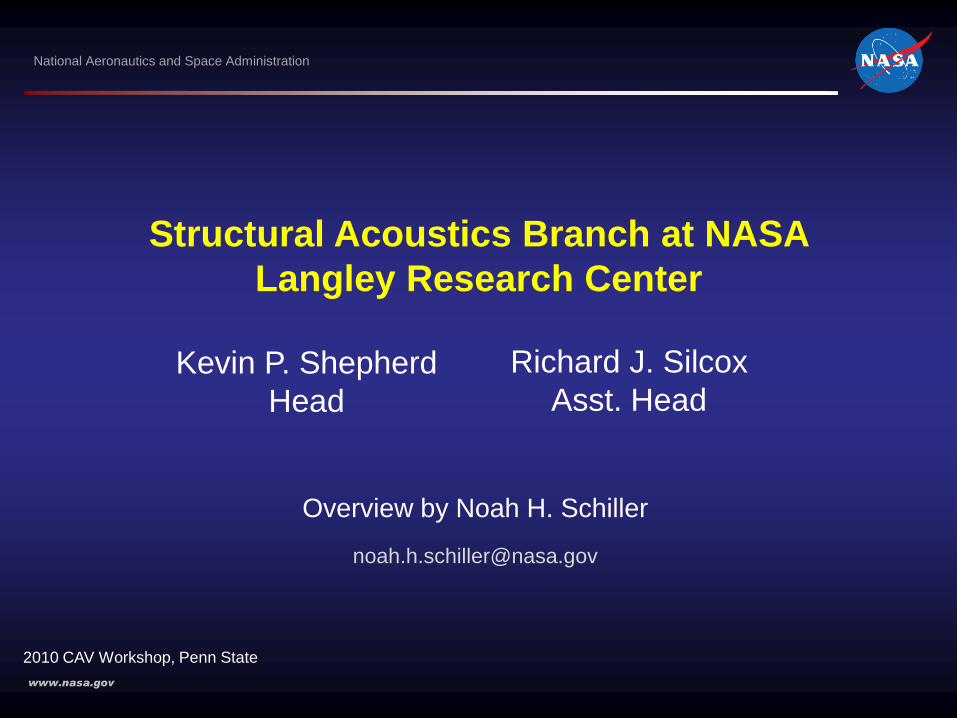
Where we fit
Aeronautics
Science
Exploration
Space Operations
Overview– 2 of 22
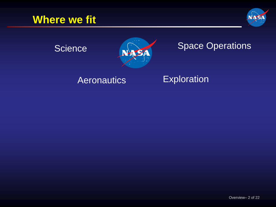
Where we fit
Aeronautics
Fundamental
Aeronautics
Subsonic Fixed
Wing
Subsonic Rotary
Wing
Supersonics
Hypersonics
Airspace
Systems
Environmentally
Responsible Aviation
Integrated Systems
Research
Aviation Safety
Aeronautics
Test
Science
Exploration
Space Operations
Overview– 3 of 22
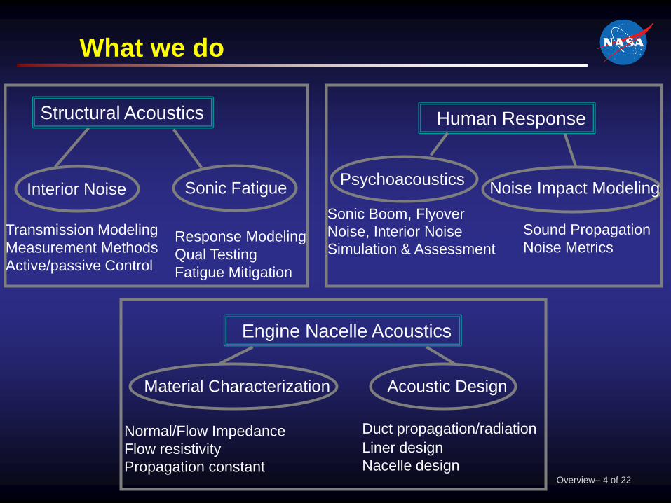
What we do
Structural Acoustics
Interior Noise Sonic Fatigue
Human Response
Psychoacoustics
Engine Nacelle Acoustics
Noise Impact Modeling
Acoustic DesignMaterial Characterization
Sonic Boom, Flyover
Noise, Interior Noise
Simulation & Assessment
Sound Propagation
Noise MetricsResponse Modeling
Qual Testing
Fatigue Mitigation
Transmission Modeling
Measurement Methods
Active/passive Control
Normal/Flow Impedance
Flow resistivity
Propagation constant
Duct propagation/radiation
Liner design
Nacelle designOverview– 4 of 22

Facilities
Overview– 5 of 22
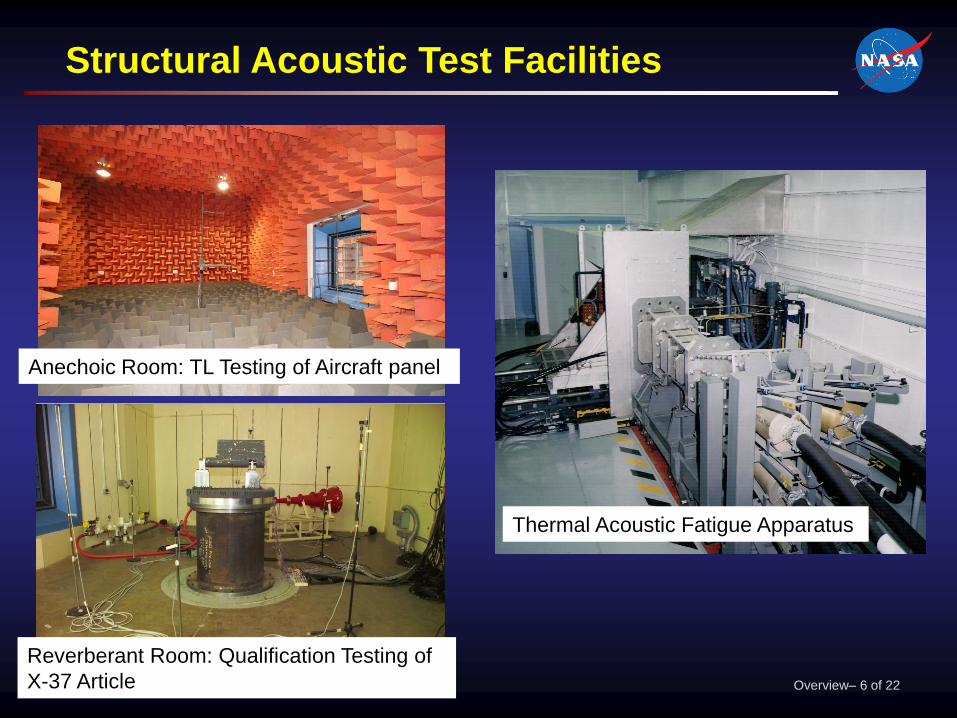
Anechoic Room: TL Testing of Aircraft panel
Reverberant Room: Qualification Testing of
X-37 Article
Structural Acoustic Test Facilities
Thermal Acoustic Fatigue Apparatus
Overview– 6 of 22

Human Response Test Facilities
Interior Effects
Room
Exterior Effects
Room
Sonic Boom
Simulator
Overview– 7 of 22

Normal Incidence Tube (NIT)
Acoustic Liner Technology Facility
Raylometer
Grazing Flow Impedance Tube
Curved Duct Test Rig
Overview– 8 of 22

Recent Activities
Overview– 9 of 22

Quiet Honeycomb Panels
Recessed Core Panel
Voided Core Panel
Solid Core Panel Overview– 10 of 22
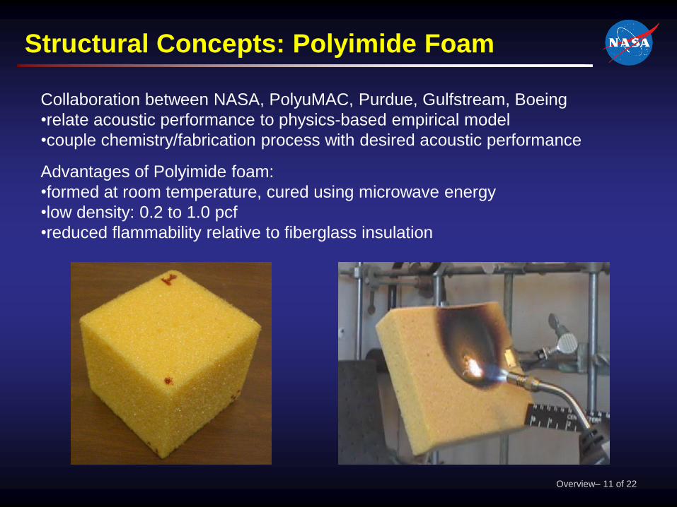
Structural Concepts: Polyimide Foam
Collaboration between NASA, PolyuMAC, Purdue, Gulfstream, Boeing
•relate acoustic performance to physics-based empirical model
•couple chemistry/fabrication process with desired acoustic performance
Advantages of Polyimide foam:
•formed at room temperature, cured using microwave energy
•low density: 0.2 to 1.0 pcf
•reduced flammability relative to fiberglass insulation
Overview– 11 of 22
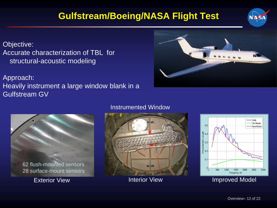
Gulfstream/Boeing/NASA Flight Test
Objective:
Accurate characterization of TBL for
structural-acoustic modeling
Approach:
Heavily instrument a large window blank in a
Gulfstream GV
Instrumented Window
Exterior View Interior View Improved Model
62 flush-mounted sensors
28 surface-mount sensors
Overview– 12 of 22

NASA Langley Gulfstream
Lockheed-Martin
Sonic Boom Testing - Simulation & Flight
NASA Dryden
Overview– 13 of 22

Quiet rotorcraft cabins
Overview– 14 of 22

Technical Challenge: Quiet Cabin
Goal: Cabin noise 77 dBA SPL with no additional weight penalty
Powertrain noise is important
• high frequency tones
Approach:
• reduce source noise
• improve modeling tools
• develop novel structural concepts
Overview– 15 of 22

High Frequency Vibroacoustic Modeling
support beams, trans.
housing: long wavelength
acoustic space,
sidewall panels: short
wavelength
Goal: Get noise into vehicle design
• Statistical Energy Analysis (SEA) is preferred
• expertise required
• separate model must be generated
• Energy finite elements (EFE) are alternative
• analyzes coarse finite element model
• automates structure partitioning
Overview– 16 of 22

Test Structure: Composite Cylinder
Overview– 17 of 22

Automated Impulse Response Decay Method
0 0.05 0.1 0.15-30
-25
-20
-15
-10
-5
0
5
Measured FRFs* Impulse responses
Schroeder decays Fit initial [-2,-17] dB
of decay
FFT-1
*Important details: Jacobsen and Bao, JSV, 115(3): 521-537, 1987.
• loss factor:
• goodness of fit
metric: R2
(0<R2<1)
regression: fit with
single exponential
Results
filter*
1/3-octave response
Overview– 18 of 22

Vibroacoustic modeling
drive point
Horizontal variation of v2 at 2 kHz
v2 prediction in 2 kHz 1/3-octave
band using default power
transmission coefficients
due to errors
in pwr. trans.
coeffs
due to
model
errors
Overview– 19 of 22
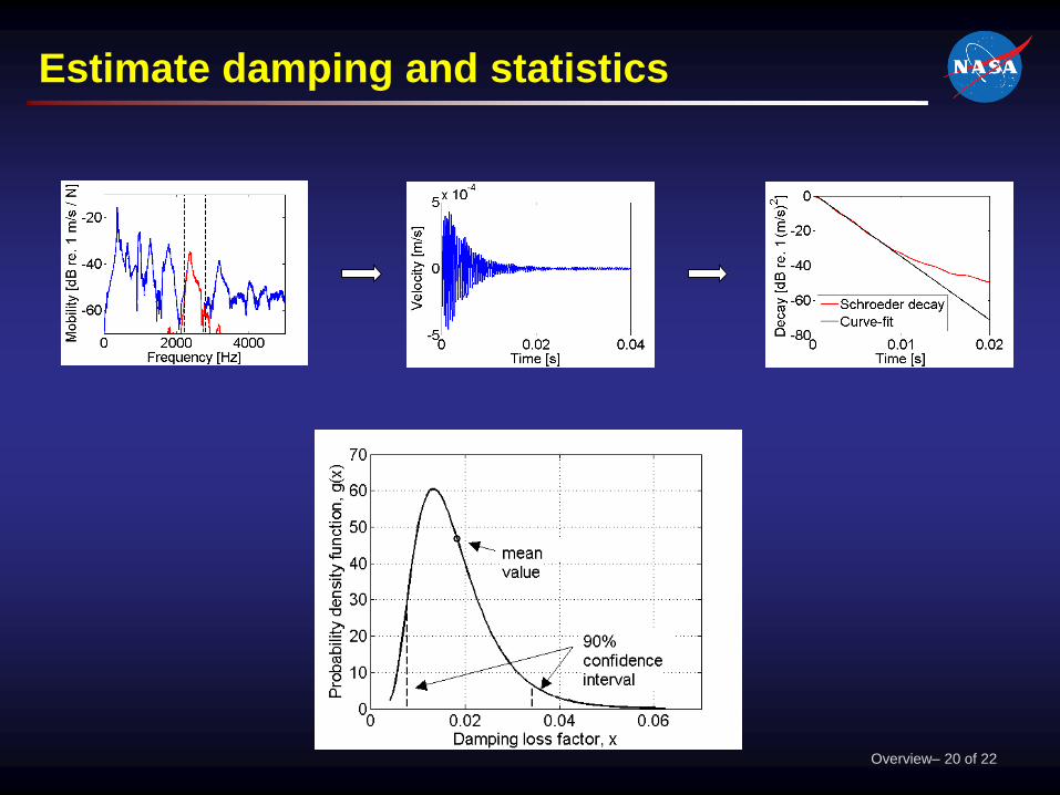
Estimate damping and statistics
Overview– 20 of 22

Propagate damping uncertainty through model
Overview– 21 of 22

Concluding remark
Structural Acoustics Branch conducts research to
understand and control noise and its effects on
aircraft, passengers, crew, and the community
Overview– 22 of 22