Strontium ferrite permanent magnet-An overview -...
6
Indian Journal of Engineering & Materials Sciences Vol. 7, October-December 2000, pp. 364-369 Strontium ferrite permanent magnet-An overview Amitabh Verma a , 0 P Pandeyb & Puneet Sharma b bThapar Institute of Engineering and Techno l ogy , Patiala 147 001, India a Materials Science Di vision, Thapar Centre for Industrial Research and Development, Patiala 147001 , India Recei ved 25 February 2000; accepted 23 Novell/ber 2000 Among the permanent magnets hard ferrites, particularly M-type hexagonal ferrites (Sr-Ferrite and Sa -Ferrite) have special place by virtue of their low co st and reasonable magnetic properties. This paper gives a brief introduction of hard ferrites with special reference to strontium ferrite permanent magne t. Processing of, sintered and plastic - bonded magnet has been discussed. The effect of composition of strontium ferrite powders and that of various additives, such as CaO, Si0 2 , AI 2 0 ), etc. on the magnetic properties have also been outlined. Magnetic materials can be classified into two groups, i.e. magnetically soft (easy to magnetize and demagnetize) and magnetically hard materials (difficu lt to magnetize and demagnetize). Some important hard magnetic materials are ferrites , Alnicos, rare earth - transition metal compounds. In the class of magnets, ferrites enjoy a unique position due to their commercial importance. Ferrites can be described as a class of magnetic oxide which contain iron oxi de as the principal component. Hard fen"ites have a hexagonal structure and can be classified in M-, X-, Y- , W-, Z- type fen"ites and given by the formulae: M-type -R Fel 2 01 9 R = Ba, Sr, Pb . W-type - R Me2 Fe1 60 27 Me =Fe 2 +, Ni 2 +, Mn 2 + etc. X - type - R Me Fe28 0 46 Y - type - R2 Me2 Fel 2 0 22 Z - type - R3 Me2 Fe24 0 41 W- , X- , Y- , Z- ty pe ferrites are not interesting economically because of their relatively difficult processing, but the M-type ferrites, isostructural with magnetoplumbite, are by far th e most important hexagonal fen"ites. M-type Ferrites are mainly used as permanent magnet materials, that have stron g re sistance to demagnetizing field once they get magnetized and have a do min a nt pos ItI on in permanent magnet marke t. They are pre ferred over Alnic os due to lo we r material and process in g cost and sup eri or coercivity. Sr-Ferrite and Ba-Ferr it e are th e two main mate rial s in th e M-type ferrite fam il y. These ferrit es have moderate magnetic properties and pri ce per unit of available magnetic energy is low . Comparative properties of M-type ferrite with that of other magnets are given below in Table 11. Comparison shows that rare earth-based magnets have very high magnetic properties than ferrites, but at present they cost more than ferrites. Presently, their use is limited to these applications which call for miniaturization . Crystal Chemistry and Physical Properties Barium and strontium ferrite have the same cr ys tal structure as magnetoplumbite. The hexagonal unit cell of Sr-Ferrite is shown in Fig. 11 and sch ematic representation of Sr.Ferrite structure in Fig. 22 Sr Ferrite has the Chemical Formula Sr" Fe"" 0 ',,, The hexagonal unit cell of Strontium Ferrite contains 2 molecules or total 2x32 = 64 atoms. It is very lon g in c-direction (c=2.32nm and a=0.588 nm). Sr" and 0 ' are both large and closely packed. The smaller Fe" ions are located in the interstices. The structural unit is bui lt up of smaller units: a cubic block having spinel structure and a hexa go nal block containing Sr" -ion. The unit ce ll is built up by stacking of layers of these atoms one on top of another. Fig. 2 shows 10 layers of large ion s (Sr",O') Table I- Magne ti c prope rti es of Co mmon permanent magnets S. Mate ri als B f ;H c (B H)ma, No. (mT) kAhn ( I-; J/m') I. Alnico 650 40-45 42-45 2. Ferrites 350-400 240-320 27 .5-31.5 3. Sm Co 1 05 0- 11 50 880- 1360 145- 160 4. Nd-Fe-B 1200-1300 800- 1200
-
Upload
truongphuc -
Category
Documents
-
view
214 -
download
0
Transcript of Strontium ferrite permanent magnet-An overview -...
Indian Journal of Engineering & Material s Sciences Vol. 7, October-December 2000, pp. 364-369
Strontium ferrite permanent magnet-An overview
Amitabh Vermaa, 0 P Pandeyb & Puneet Sharmab
b Thapar Institute of Engineering and Technology, Patiala 147 001, India a Material s Science Di vision, Thapar Centre for Industrial Research and Deve lopment, Patiala 147001 , India
Received 25 February 2000; accepted 23 Novell/ber 2000
Among the permanent magnets hard ferrites, particularly M-type hexagonal ferrites (Sr-Ferrite and Sa-Ferrite) have special place by virtue of their low cost and reasonable magnetic properties. This paper gives a brief introduction of hard ferrites with special reference to strontium ferrite permanent magnet. Processing of, sintered and plastic - bonded magnet has been di scussed. The effect of composition of strontium ferrite powders and that of various additives, such as CaO, Si02,
AI 20 ), etc. on the magnetic properties have also bee n outlined.
Magnetic materials can be classified into two groups, i.e. magnetically soft (easy to magnetize and demagnetize) and magnetically hard materials (difficult to magnetize and demagnetize). Some important hard magnetic materials are ferrites , Alnicos, rare earth - transition metal compounds. In the class of magnets, ferrites enjoy a unique position due to their commercial importance. Ferrites can be described as a class of magnetic oxide which contain iron oxide as the principal component. Hard fen"ites have a hexagonal structure and can be classified in M-, X-, Y-, W-, Z- type fen"ites and given by the formulae:
M-type - R Fel2019 R = Ba, Sr, Pb.
W-type - R Me2 Fe160 27 Me =Fe2+, Ni2+, Mn2
+ etc.
X - type - R Me Fe28 0 46
Y - type - R2 Me2 Fel2 0 22
Z - type - R3 Me2 Fe24 0 41
W-, X-, Y-, Z- type ferrites are not interesting economically because of their relatively difficult processing, but the M-type ferrites, isostructural with magnetoplumbite, are by far the most important hexagonal fen"ites. M-type Ferrites are mainly used as permanent magnet materials, that have strong resistance to demagnetizing field once they get magnetized and have a dominant posItIon in permanent magnet market. They are preferred over Alnicos due to lower material and process ing cost and superior coercivity . Sr-Ferrite and Ba-Ferrite are the two main material s in the M-type ferrite fam ily. These ferrites have moderate magnetic properties and pri ce
per unit of available magnetic energy is low. Comparative properties of M-type ferrite with that of other magnets are given below in Table 11. Comparison shows that rare earth-based magnets have very high magnetic properties than ferrites , but at present they cost more than ferrites. Presently, their use is limited to these applications which call for miniaturization.
Crystal Chemistry and Physical Properties Barium and strontium ferrite have the same crystal
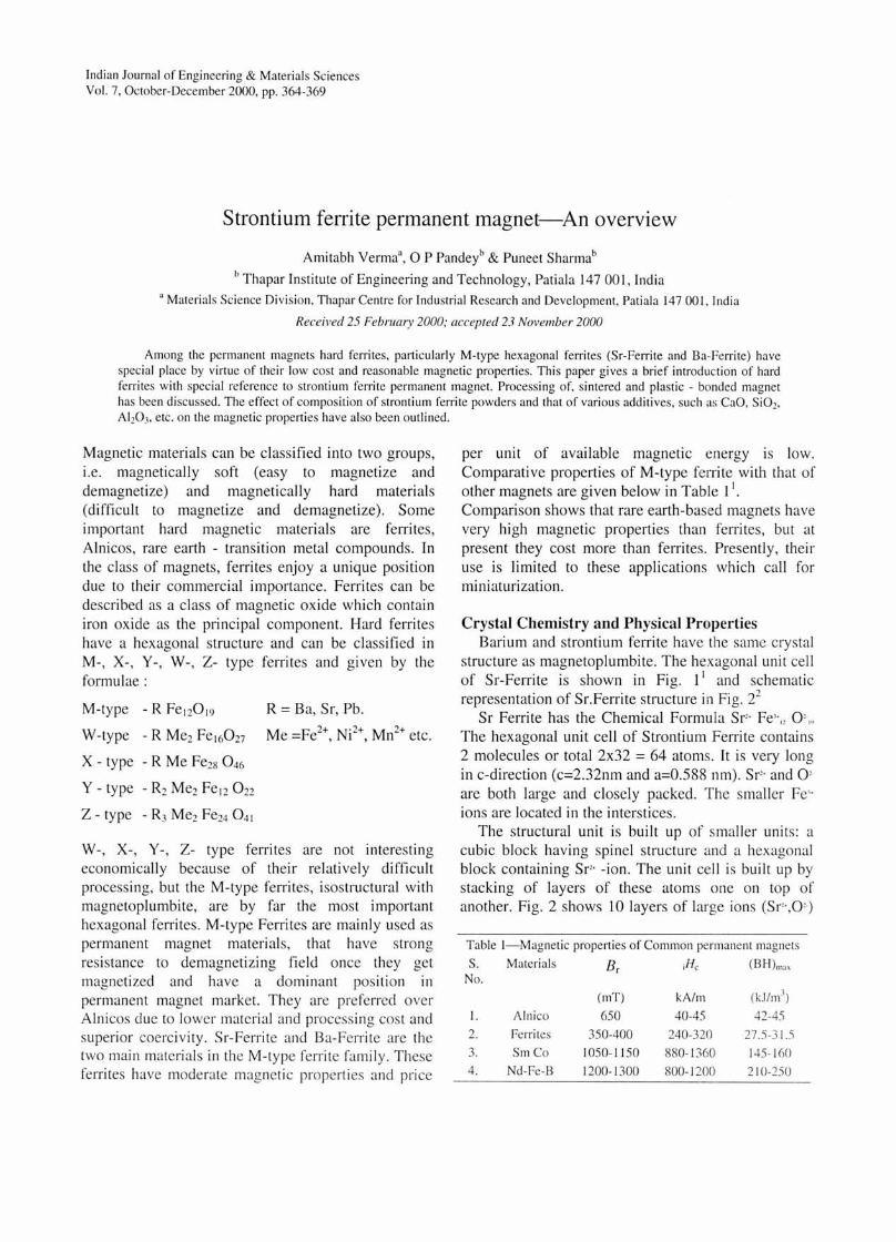
structure as magnetoplumbite. The hexagonal unit cell of Sr-Ferrite is shown in Fig. 11 and schematic representation of Sr.Ferrite structure in Fig. 22
Sr Ferrite has the Chemical Formula Sr" Fe"" 0 ',,, The hexagonal unit cell of Strontium Ferrite contains 2 molecules or total 2x32 = 64 atoms. It is very long in c-direction (c=2.32nm and a=0.588 nm) . Sr" and 0 ' are both large and closely packed. The smaller Fe" ions are located in the interstices.
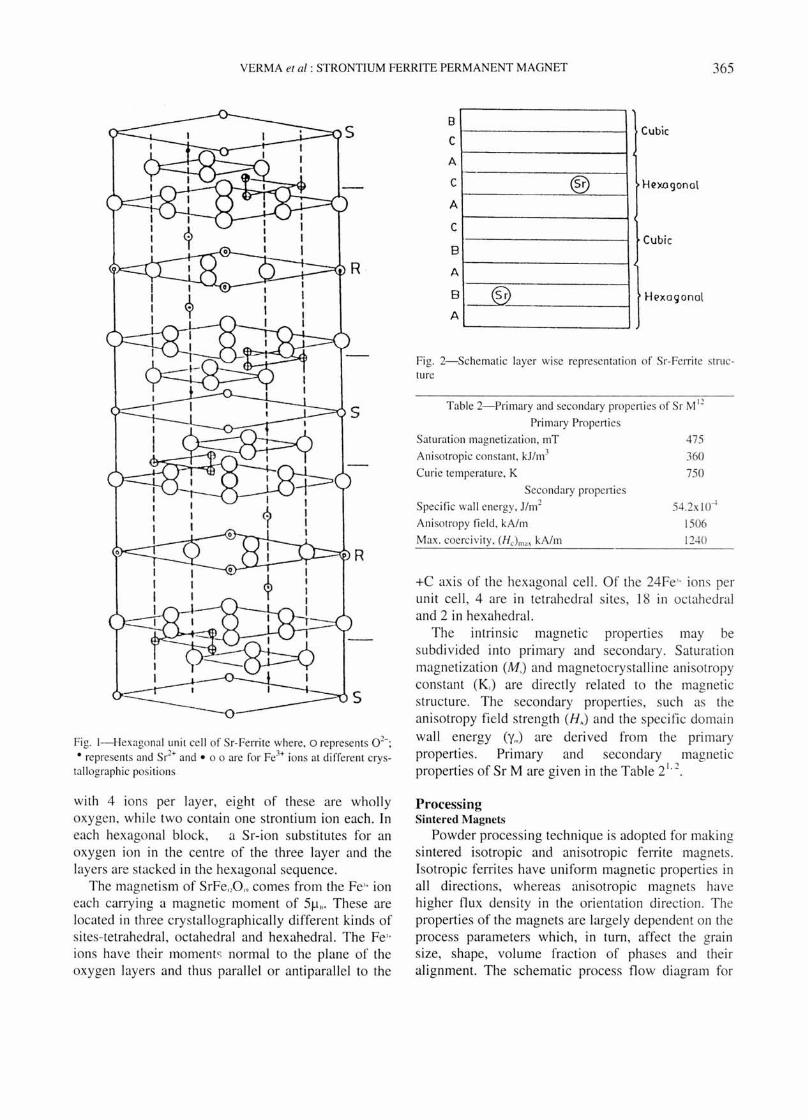
The structural unit is bui lt up of smaller units: a cubic block having spinel structure and a hexagonal block containing Sr" -ion. The unit cell is built up by stacking of layers of these atoms one on top of another. Fig. 2 shows 10 layers of large ions (Sr",O')
Table I- Magnetic properti es of Co mmon permanent magnets
S. Materi als Bf ;Hc (B H)ma,
No.
(mT) kAhn ( I-;J/m')
I. Alnico 650 40-45 42-45
2. Ferrites 350-400 240-320 27 .5-31.5 3. Sm Co 1050- 11 50 880- 1360 145- 160 4. Nd-Fe-B 1200- 1300 800- 1200 2 1 0-~50
VERMA el at: STRONTIUM FERRITE PERMANENT MAGNET 365
Fig. I- Hexagonal unit cell of Sr-Ferrite where, 0 represents 0 2- ;
• represents and Sr2+ and . 00 are for Fe3+ ions at different crystallographic positions
with 4 ions per layer, eight of these are wholly oxygen, while two contain one strontium ion each. In each hexagonal block, a Sr-ion substitutes for an oxygen ion in the centre of the three layer and the layers are stacked in the hexagonal sequence.
The magnetism of SrFe"O" comes from the Fe" ion each carrying a magnetic moment of 5f.1l1' These are located in three crystallographically different kinds of sites-tetrahedral , octahedral and hexahedral. The Fe" ions have their moments normal to the plane of the oxygen layers and thus parallel or anti parallel to the
8
C
A
C
A
C
B
A
B
A ~
®
Cubic
H(!xogonol
Cubic
Fig. 2-Schematic layer wise representati on o f Sr-Ferrite structure
Table 2-Primary and secondary properties of Sr M I2
Primary Properti es
Saturati on magnetizati on, mT
Ani sotropic constant, kJ/m3
Curie temperature, K
Secondary properti es
Specific wall energy, J/m2
Ani sotropy fi eld , kNm
Max. coercivity, (Hc)max kA/m
475
360 750
54.2xlO·-l
1506 1240
+C axis of the hexagonal cell. Of the 24Fe" ions per unit cell , 4 are in tetrahedral s ites, 18 in octahedral and 2 in hexahedral.
The intrinsic magnetic properties may be subdivided into primary and secondary. Saturation magnetization (M,) and magnetocrystalline anisotropy constant (K.) are directly related to the magnetic structure. The secondary properties , sLlch as the anisotropy field strength (H.) and the specific domain
wall energy (Ym) are derived from the primary properties. Primary and secondary magnetic properties of Sr M are given in the Table 21.2.
Processing Sintered Magnets
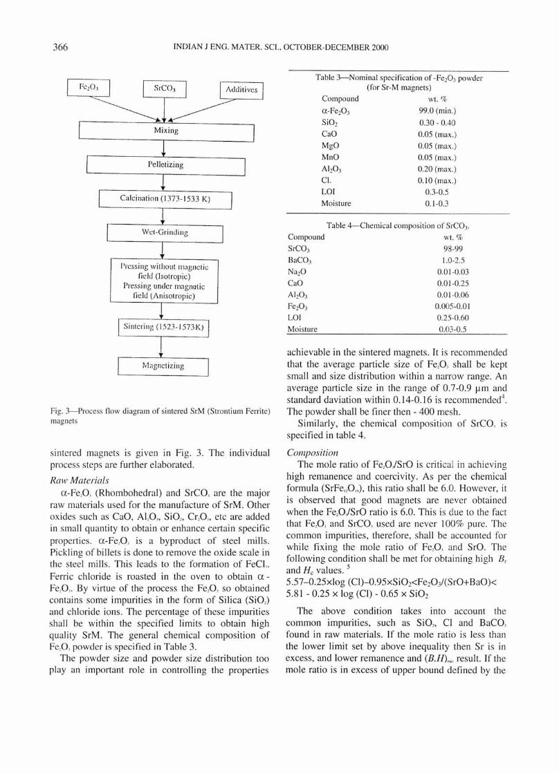
Powder processing technique is adopted for making sintered isotropic and anisotropic ferrite magnets. Isotropic ferrites have uniform magnetic properties in all directions, whereas anisotropic magnets have higher flux density in the orientation directi on. The properties of the magnets are largely dependent on the process parameters which, in turn, affect the grain size, shape, volume fraction of phases and their alignment. The schematic process flow diagram for
366 INDIAN J ENG. MATER. SCI. , OCTOBER-DECEMBER 2000
Mixing
Pelletizing
Calcination (1373- 1533 K)
Wl:I-Grilldillg
I'rl:ssing without magncti c field (isotropic)
Press ing under magnoti c lIe ld (Anisotropic)
Fi g. 3--Process fl ow diagram o f sintered SrM (Strontium Ferrite) magnets
sintered magnets is given in Fig. 3. The individual process steps are further elaborated.
Raw Materials u -Fe,Q, (Rhombohedral) and SrCQ, are the major
raw material s used for the manufacture of SrM . Other oxides such as CaO, ALO ... SiO" Cr,O" etc are added in small quantity to obtain or enhance certain specific properties . u -Fe,O, is a byproduct of steel mills. Pi ck ling of billets is done to remove the oxide scale in the steel mills . This leads to the formation of FeCI,. Fen-ic chloride is roasted in the oven to obtain uFe,Q,. By virtue of the process the Fe,Q, so obtained contains some impurities in the form of Silica (SiO,) and chloride ions. The percentage of these impurities shall be within the specified limits to obtain high quality SrM. The general chemical composition of Fe,O, powder is specified in Table 3.
The powder size and powder size distribution too play an important role in controlling the properties
Table 3--Nominal specification o f -Fe203 powder (for Sr-M magnets)
Compound wt. %
u-Fe20 3 99.0 (min .)
SiOz 0.30 - DAD CaO 0.05 (max.)
MgO 0.05 (max. )
MnO 0.05 (max. )
Alz0 3 0.20 (max. )
Cl. 0.10 (max. )
LO! 0.3-0.5
Moisture 0.1-0.3
Table 4--(:hemical composition of SrCOJ .
Com~u~ wt. %
SrCO) 98-99
BaCO) 1.0-2.5
NazO 0.01-0.03
CaO 0.01 -0.25 AI 20 3 0.01 -0.06
Fez0 3 0.005-0.0 1
LO! 0.25-0.60
Moisture 0.03-0.5
achievable in the sintered magnets. It is recommended that the average particle size of Fe,O, shall be kept small and size distribution within a narrow range. An average particle size in the range of 0.7-0.9 ~m and standard daviation within 0.1 4-0.16 is recommended4
.
The powder shall be finer then - 400 mesh . Similarly, the chemical composition of SrCO, is
specified in table 4.
Composition The mole ratio of Fe,QJSrO is critical in achieving
high remanence and coercivity . As per the chemical formula (SrFe"O,.,), this ratio shall be 6.0. However, it is observed that good magnets are never obtained when the Fe,O/SrO ratio is 6.0. This is due to the fac t that Fe,Q, and SrCO, used are never 100% pure. The common impurities, therefore, shall be accounted for while fixing the mol e ratio of Fe,O, and SrO. The following condition shall be met for obtaining hi gh Br and He values. 5
5.57-0.25xlog (CI)-0.95xSi02<Fe20 3/(SrO+BaO)< 5.81 - 0.25 x log (CI) - 0.65 x Si02
The above condition takes into account the common impurities, such as SiO" CI and BaCO, found in raw materials . If the mole ratio is less than the lower limit set by above inequality then Sr is in excess, and lower remanence and (B.H)~. result. If the mole ratio is in excess of upper bound defined by the
VERMA et of: STRONTIUM FERRlTE PERMANENT MAGNET 367
inequality then excessive liquid phase is formed during sintering, and coercive force is reduced due to abnormal grain growth. In order to check the grain growth during calcination, a small percentage of SiO, (0.1-1.0 wt.%) is added to the starting mixture. Normally, the SiO, percentage is kept below 0.5 wt%. Presence of SiO, allows calcination at higher temperature without grain growth.
Calcination Calcination facilitates solid state diffusion of SrO
and Fe,O,. If the calcination temperature is low then grains of uniform SrM are not formed. Similarly, if the calcination temperature is too high, excessive grai n growth occurs and coarse grain SrM is formed. An optimum temperature for calcination is decided based on sil ica content in Fe,O, powder.
Wet Grinding Wet grinding is carried out in ball mills to obtain
powder of narrow particle size distribution. Average particle size in the range of 0.7 - 0.9 f..Im is recommended for achieving good magneti c properties. Moreover, the standard deviation shall not be very large. The standard deviation in the range of 0.14-0.16 has been found to be optimum. Particle size below 0.7 f..Im poses problem in compaction and gives poor green density. Particles above 0.9 f..Im adversely affect the coercivity. Needless to say , the critical domain size of SrM has been calculated to be 0.5 f..Im . A broad particle size distribution may lead to abnormal grain growth. Abnormal grain growth affects the magnet properties as the properties change from grain to grain.
COli/pact ion The powder is compacted wet or dry in the
presence or absence of magnetic field. Pressing under the magnetic field is done to obtain an isotropic magnet by aligni ng powder in the direction of magnetic field. Invariably, powder in the form of a sluny is compacted to obtain high performance anisotropic magnets . Wet sltlITY assists in better orientation as well as density. Dry compaction of the powders is also possible. Polyvinyl alcohol and camphor are used as binder6
. These binders are removed during sintering. It is possible to manufacture both isotropic and anisotropic magnets by dry pressing. The direction of the applied magnetic field during pressing may be parallel or perpendicular to the pressing direction. The magnetic properties obtained in perpendicular pressing has been found to
be better then parallel field. 0.5-1.0 T field in the die cavity has been found to be adequate for magnetic alignment. The remanence is strongly affected by the magnetic pressing as it is given by the following formula' :
Br = j(d/dx).S.1.
where j is the degree of alignment; d/dx the relative density and S the fraction of pure ferrite in the solid. The value of j is 0.5 and 0.9 for isotropic and anisotropic magnets, respectively. The relative density is generally 0.9 and fraction of pure ferrite 0.98. Compaction pressure in the range of 5-15 MPa has been found to be sufficient in wet pressing. However, higher compaction pressure is required for dry powder and it is in the range of 40-80 MPa.
Silltering Sintering is carried out to bring about bonding
between the powder particles and effect densification. Sintering is carried out in the temperature range of 1373 - 1573 K. However, care is taken to avoid excessive grain coarsening during sintering. Typical sintered magnets have - grain size of I f..Im, which is somewhat bigger than the critical domain size, but sufficiently small to avoid domains down to considerable reverse fields . Magneti zation reversal proceeds by nucleation and growth of domains. On a macroscale the reversal process is nonuniform, being governed by the initiation and growth of multicrystal reversed regions. On this basis the coercivity expression is proposed as follows:
Hh = aH, - bis/p"
where the first term represents the average internal field needed to nucleate a reverse domain. The coefficient ' a' ranges from 0 to 1 and depends mainly on grain size. The second term represents the effect of internal demagnetization field . The coefficient 'b' ranges from 0 to 2 and depends on the remanence and the crystal demagnetizing factor N, determined by the crystal shape. The value of N is 0 if the particles are needle shaped and I for thin plates. For platelet shape particles, which is generally obtained in the case of SrM, the value of N lies in the range of 0.6 - 0.9.
The crystal shape and size can be controlled with the help of additives and sintering temperature. SiO" CaO, Cr,O" AI,O" Sb,O, and SrO are added to calcined powder to control grain growth. However, the concentration of SiO" CaO, Sb,O" etc have to be controlled in a narrow range if magnets of high Br
368 INDIAN J ENG. MATER. SCI.. OCTOBER-DECEMBER 2000
and H values are to be obtained. The range in which the additions are used is given in Table 57
,8 .
Ah03 and Cr203 can be used alternatively as both have grain pinning effect. Si02 and CaO are generally used in combination as together they form a liquid phase which helps in densification. The mole ratio of CaO/Si02 is kept between 0.6-0.8. It has been observed that coercivity is low when Si02 is less than 0.3 wt%. If Si02 percentage is more than 0.6 wt.% the Br value is reduced. Similarly, the coercivity was found to be higher when CaO percentage was less than 0.3 wt. %. However, the Br value was found to be less as the sintering was not proper below this value. Above 0.6 wt. % of CaO, the sintering was satisfactory, but coercivity reduced. Both Ah03 and Cr20 3 improve coercivity but reduce remanence as the percentage of ferrite is reduced. Sb20 3 in small percentage alongwith CaO and Si02 has been found to give high Br as well as He.
Invariably, the sintering temperature is 80-120k lower than the calcination temperature in order to check the grain growth. A general expression for calculating optimum sintering temperature when CaO/SiO, ratio is in the range of 0.6-0.8 and powder contains small percentage of ALO, is given below.7
TSint(OC) = (-30A-13) ...JTeal + 1100 (A) + 1670
where T", is the calcination temperature in °C and A is the wt. % of ALO,
Final Magnetization Final magnetization is carried out at a field which
is 2.5-3 times higher then the intrinsic coercivity. Thus, the final magnetization is done at 1.2-1.5T.
Bonded Magnets Useful magnets can be made by bonding strontium
ferrite powder in various resins, plastics or natural rubber. If no special steps are taken, the material is isotropic and energy product is unlikely to exceed 5.5 kJ/m'. If good flexibility is required the proportion of ferrite powder must not be too large and (B.H.)~.
becomes considerably lower.
Table 5-Percentage range of additives in SrM7•8
Additives wt. %
CaO 0.3-0.6
SiOl 0.3-0.6
AI 20 3 0.1-0.4
Cr20 3 0.1-0.4
Sb20 3 0.05-0.15
srO 0.01-1.0
A number of processing techniques, such as compression moulding, injection moulding, rolling etc. may be employed for making polymer bonded magnets. It is possible to make anisotropic magnets by carrying out the said processes under a magnetic field which is suitably oriented. By alignment of powders it is possible to achieve energy product as high as 12 kJ/m' in bonded ferrite magnets. The Br value of these magnets is largely dependent on the volume fraction of the strontium ferrite powder.
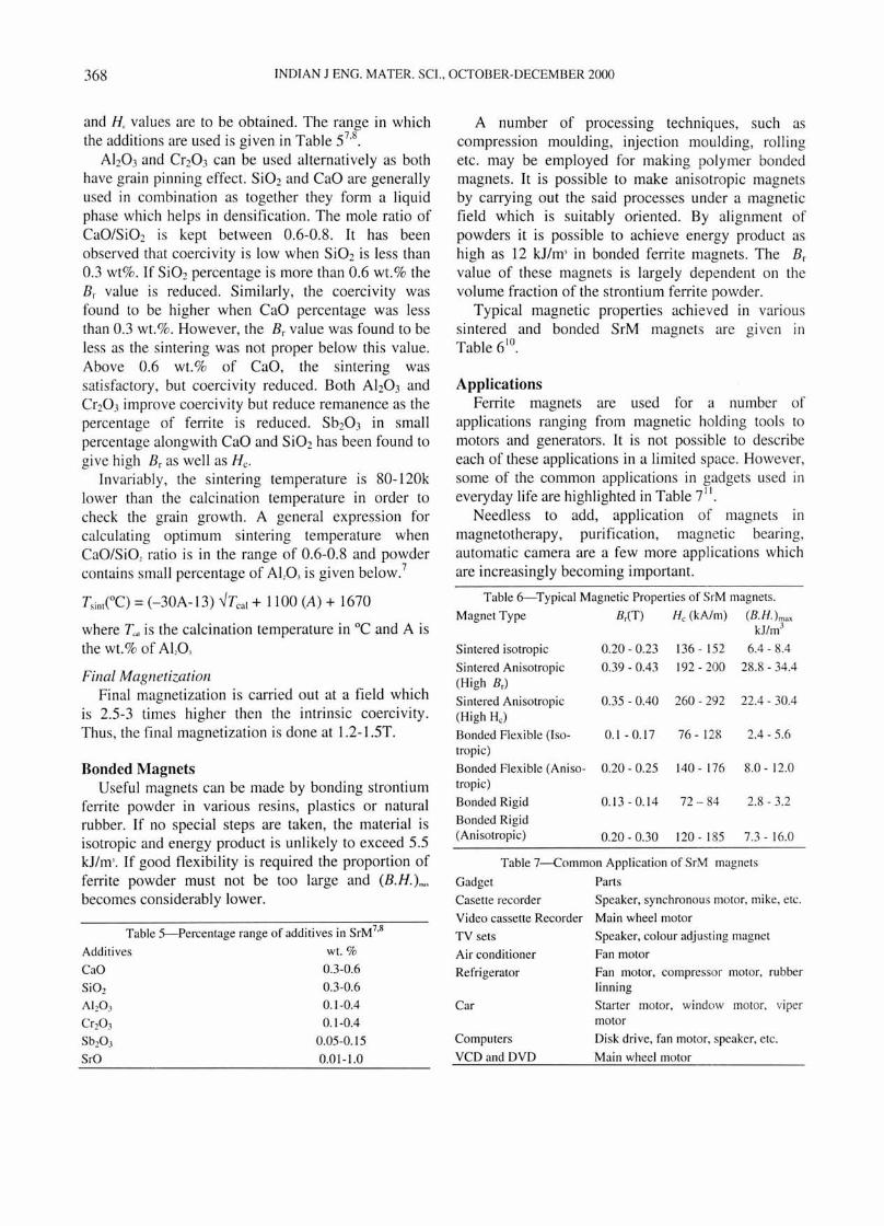
Typical magnetic properties achieved in various sintered and bonded SrM magnets are given in Table 610.
Applications Ferrite magnets are used for a number of
applications ranging from magnetic holding tools to motors and generators. It is not possible to describe each of these applications in a limited space. However, some of the common applications in gadgets used in everyday life are highlighted in Table i I.
Needless to add, application of magnets in magnetotherapy, purification, magnetic bearing, automatic camera are a few more applications which are increasingly becoming important.
Table 6-Typical Magnetic Properties of SrM magnets.
Magnet Type B~(T) He (kAlm) (B·H.) max kJ/m3
Sintered isotropic 0.20 - 0.23 136 - 152 6.4 - 8.4
Sintered Anisotropic 0.39 - 0.43 192 - 200 28.8 - 34.4 (High B,)
Sintered Anisotropic 0.35 - 0.40 260 - 292 22.4 - 30.4 (High He)
Bonded Flexible (Iso- 0.1 - 0.17 76 - 128 2.4 - 5.6 tropic)
Bonded Flexible (Aniso- 0.20 - 0.25 140 - 176 8.0 - 12.0 tropic)
Bonded Rigid 0.13 - 0.14 72 - 84 2.8 - 3.2
Bonded Rigid (Ani sotropic) 0.20 - 0.30 120 - 185 7.3 - 16.0
Table 7-Common Application of SrM magnets
Gadget Parts
Casette recorder Speaker, synchronous motor, mike. etc.
Video cassette Recorder Main wheel motor
TV sets
Air conditioner
Refrigerator
Car
Computers
VCD and DVD
Speaker. colour adjusting magnet
Fan motor
Fan motor. compressor motor. rubber linning
Starter motor. window motor. viper motor
Disk drive. fan motor. speaker. etc.
Main wheel motor
VERMA et al : STRONTIUM FERRITE PERMANENT MAGNET 369
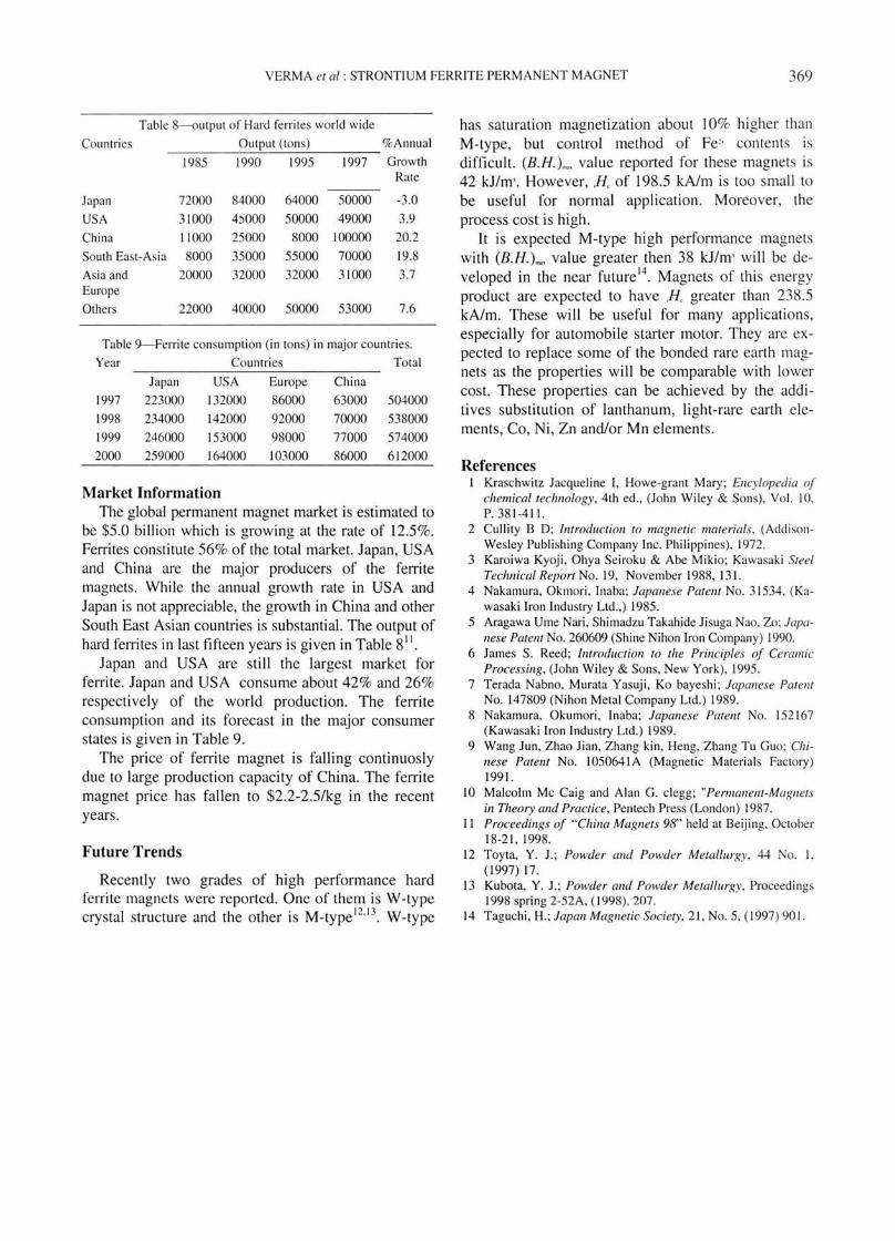
Table ~utput of Hard ferrites world wide
COllntries Output (tons) %Annual
1985 1990 1995 1997 Growth Rate
Japan 72000 84000 64000 50000 -3 .0
USA 31000 4)000 50000 49000 3.9
China 11000 25000 8000 100000 20.2
South East-Asia 8000 35000 55000 70000 19.8
Asia and 20000 32000 32000 31000 3.7 Europe
Others 22000 40000 50000 53000 7.6
Table 9--Ferrite consumption (i n tons) in major countries.
Year Countries Total
Japan USA Europe China
1997 223000 132000 86000 63000 504000
1998 234000 142000 92000 70000 538000
1999 246000 153000 98000 77000 574000
2000 259000 164000 103000 86000 612000
Market Information The global permanent magnet market is estimated to
be $5.0 billion which is growing at the rate of 12.5%. Ferrites constitute 56% of the total market. Japan, USA and China are the major producers of the ferrite magnets. While the annual growth rate in USA and Japan is not appreciable, the growth in China and other South East Asian countries is substantial . The output of hard ferrites in last fifteen years is given in Table 8 tt
.
Japan and USA are still the largest market for ferrite. Japan and USA consume about 42% and 26% respectively of the world production. The ferrite consumption and its forecast in the major consumer states is given in Table 9.
The price of ferrite magnet is falling continuosly due to large production capacity of China. The ferrite magnet price has fallen to $2.2-2.5/kg in the recent years.
Future Trends
Recently two grades of high performance hard ferrite magnets were reported. One of them is W-type crystal structure and the other is M_type I2
.13
• W-type
has saturation magnetization about 10% higher than M-type, but control method of Fe" contents is difficult. (B.H.)~, value reported for these magnets is 42 kJ/m' . However, H of 198.5 kA/m is too small to be useful for normal application. Moreover, the process cost is high.
It is expected M-type high performance magnets with (B.H.)~, value greater then 38 kJ/m' will be developed in the near future l4
. Magnets of this energy product are expected to have H greater than 238.5 kA/m. These will be useful for many applications, especially for automobile starter motor. They are expected to replace some of the bonded rare earth magnets as the properties will be comparable with lower cost. These properties can be achieved by the additives substitution of lanthanum, light-rare earth elements, Co, Ni, Zn and/or Mn elements.
References I Krasehwitz Jacqueline I, Howe-grant Mary; Encylopedia of
chemical technology, 4th ed., (John Wiley & Sons), Vol. 10, P.381-4 11.
2 Cullity B 0 ; Introduction to magnetic lIlaterials, (AddisonWesley Publishing Company Inc. Philippines), 1972.
3 Karoiwa Kyoji , Ohya Seiroku & Abe Mikio; Kawasaki Steel Technical Report No. 19, November 1988, 131.
4 Nakamura, Okmori , Inaba; Japanese Patent No. 31534. (Kawasaki Iron Industry Ltd .,) 1985.
5 Aragawa Ume Nari, Shimadzu Takahide Jisuga Nao, Zo; Japanese Patent No. 260609 (Shine Nihonlron Company) 1990.
6 James S. Reed; Introduction to the Principles of Ceramic Processing, (John Wiley & Sons, New York), 1995.
7 Terada Nabno, Murata Yasuji, Ko bayeshi; Japanese Patent No. 147809 (Nihon Metal Company Ltd .) 1989.
8 Nakamura, Okumori , Inaba; Japan ese Patent No. 152167 (Kawasaki Iron Industry Ltd.) 1989.
9 Wang Jun, Zhao Jian, Zhang kin, Heng, Zhang Tu Guo; Chinese Patent No. 1050641 A (Magnetic Materi als Factory) 1991.
10 Malcolm Me Caig and Alan G. clegg; "Permanent-Magnets in Theory and Practice, Pen tech Press (London) 1987.
II Proceedings of "China Magnets 98" held at Beijing, October 18-21 , 1998.
12 Toyta, Y. J.; Powder and Powder Metallurgy, 44 No. I, (1997) 17.
13 Kubota, Y. J.; Powder and Powder Metallurgy, Proceedings 1998 spri ng 2-52A. (1998), 207.
14 Taguehi, H.; Japan Magnetic Society, 21 , No.5, (1997) 901.