STRIPLINE KICKER STATUS
18
STRIPLINE KICKER STATUS
-
Upload
satinka-herrera -
Category
Documents
-
view
53 -
download
0
description
STRIPLINE KICKER STATUS. PRESENTATION OUTLINE Design of a stripline kicker for beam injection in DAFNE storage rings. HV tests and RF measurements of the kicker. DAFNE operation with the new kickers. Realization of a stripline kicker for ILC damping ring. - PowerPoint PPT Presentation
Transcript of STRIPLINE KICKER STATUS
STRIPLINE KICKER STATUS
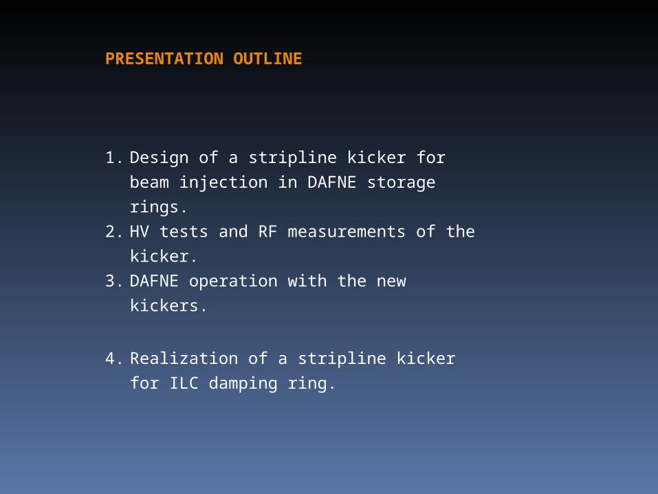
PRESENTATION OUTLINE
1. Design of a stripline kicker for beam injection in
DAFNE storage rings.
2. HV tests and RF measurements of the kicker.
3. DAFNE operation with the new kickers.
4. Realization of a stripline kicker for ILC damping
ring.
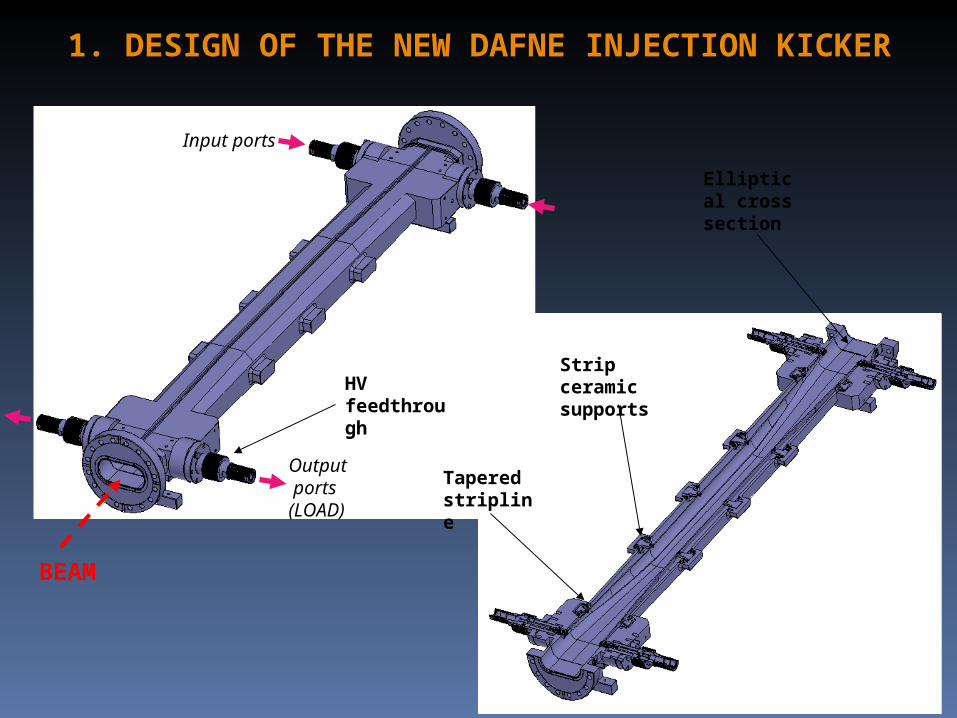
Input ports
Output ports(LOAD)
Strip ceramic supports
BEAM
1. DESIGN OF THE NEW DAFNE INJECTION KICKER
Tapered stripline
Elliptical cross section
HV feedthrough
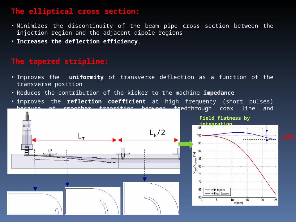
The elliptical cross section:
• Minimizes the discontinuity of the beam pipe cross section between the injection region and the adjacent dipole regions
• Increases the deflection efficiency.
The tapered stripline:
• Improves the uniformity of transverse deflection as a function of the transverse position
• Reduces the contribution of the kicker to the machine impedance
• improves the reflection coefficient at high frequency (short pulses) because of smoother transition between feedthrough coax line and stripline.
Lk/2LT 3%
Field flatness by integration
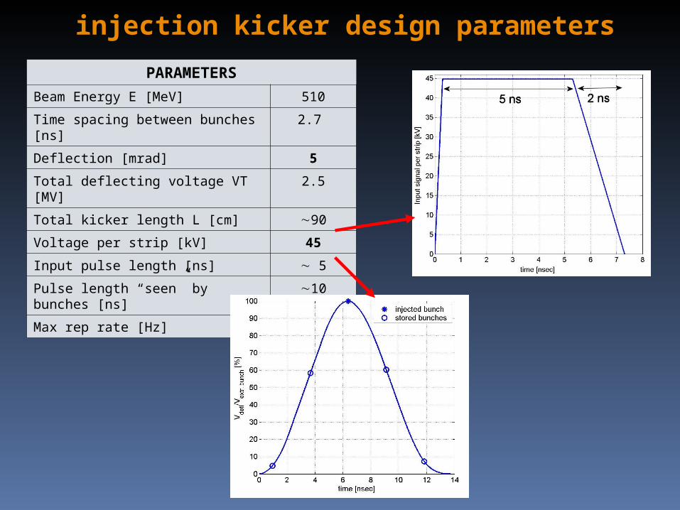
PARAMETERS
Beam Energy E [MeV] 510
Time spacing between bunches [ns] 2.7
Deflection [mrad] 5
Total deflecting voltage VT [MV] 2.5
Total kicker length L [cm] 90
Voltage per strip [kV] 45
Input pulse length [ns] 5
Pulse length “seen” by bunches [ns] 10
Max rep rate [Hz] 10
injection kicker design parameters
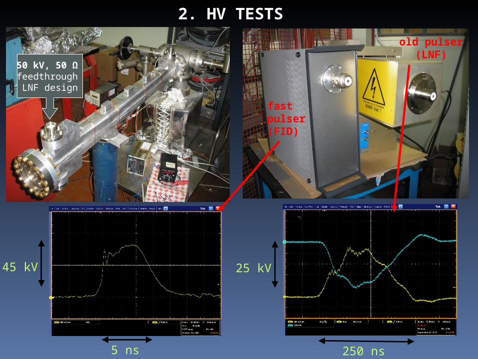
2. HV TESTS
fastpulser (FID)
old pulser(LNF)
25 kV
250 ns
45 kV
5 ns
50 kV, 50 Ω feedthrough LNF design
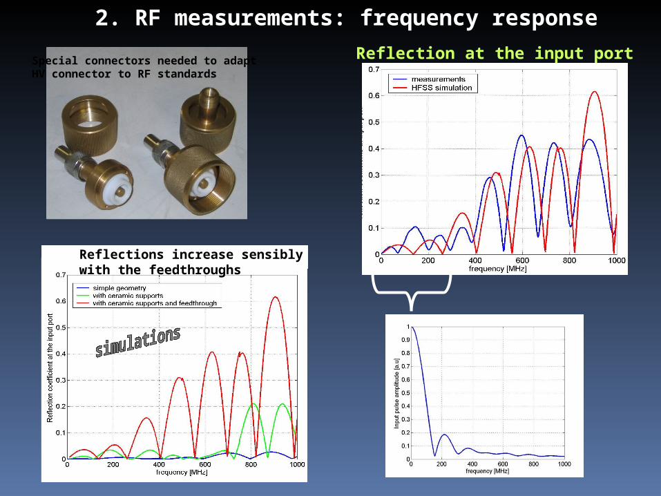
2. RF measurements: frequency response
Special connectors needed to adapt HV connector to RF standards
Reflection at the input port
Reflections increase sensiblywith the feedthroughs
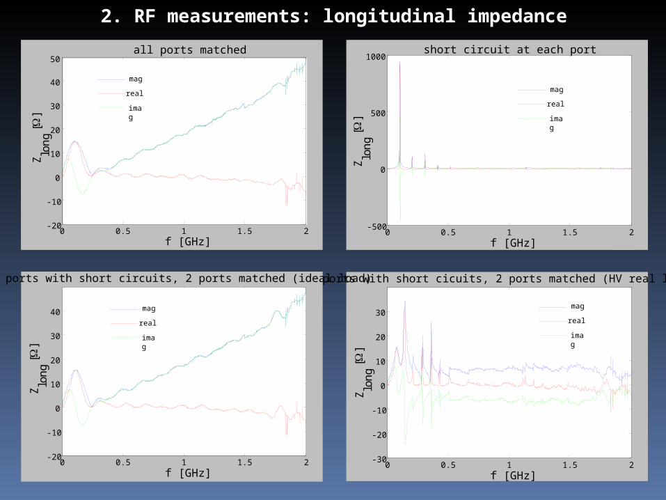
2. RF measurements: longitudinal impedance
0 0.5 1 1.5 2-20
-10
0
10
20
30
40
50
f [GHz]
all ports matched
mag
real
imag
Zlo
ng [
]
0 0.5 1 1.5 2-500
0
500
1000
f [GHz]
short circuit at each port
mag
real
imag
Zlo
ng [
]
0 0.5 1 1.5 2-30
-20
-10
0
10
20
30
f [GHz]
2 ports with short cicuits, 2 ports matched (HV real load)
Zlo
n g [
]
mag
real
imag
0 0.5 1 1.5 2-20
-10
0
10
20
30
40
f [GHz]
Zlo
ng [
]
2 ports with short circuits, 2 ports matched (ideal load)
mag
real
imag
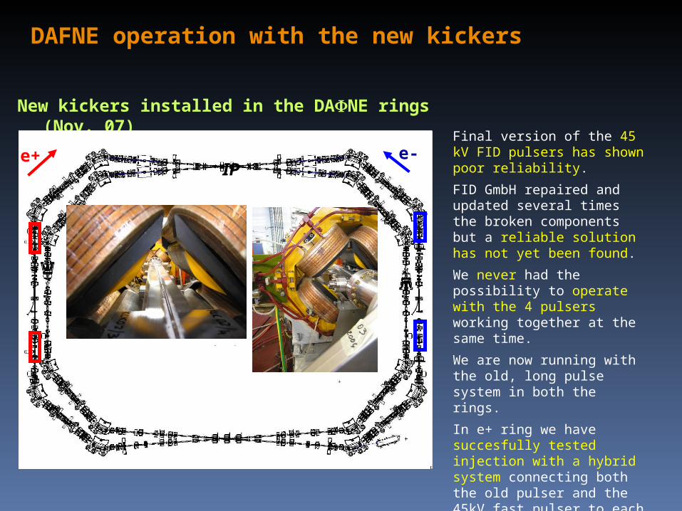
New kickers installed in the DANE rings (Nov. 07)
e+ e-IP
Final version of the 45 kV FID pulsers has shown poor reliability.
FID GmbH repaired and updated several times the broken components but a reliable solution has not yet been found.
We never had the possibility to operate with the 4 pulsers working together at the same time.
We are now running with the old, long pulse system in both the rings.
In e+ ring we have succesfully tested injection with a hybrid system connecting both the old pulser and the 45kV fast pulser to each kicker.
3. DAFNE operation with the new kickers
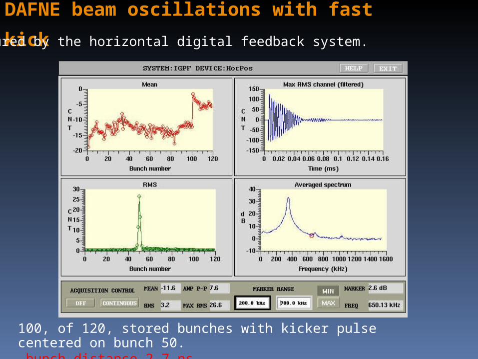
DAFNE beam oscillations with fast kick
100, of 120, stored bunches with kicker pulse centered on bunch 50. bunch distance 2.7 ns.
Measured by the horizontal digital feedback system.
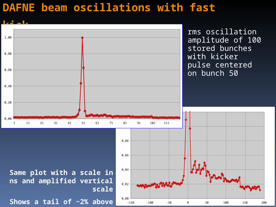
rms oscillation amplitude of 100 stored bunches with kicker pulse centered on bunch 50
DAFNE beam oscillations with fast kick
0,00
0,02
0,04
0,06
0,08
0,10
0,12
-150 -100 -50 0 50 100 150 200
Same plot with a scale in ns and amplified vertical scale
Shows a tail of ~2% above noise level
0,00
0,20
0,40
0,60
0,80
1,00
1 11 21 31 41 51 61 71 81 91 101 111
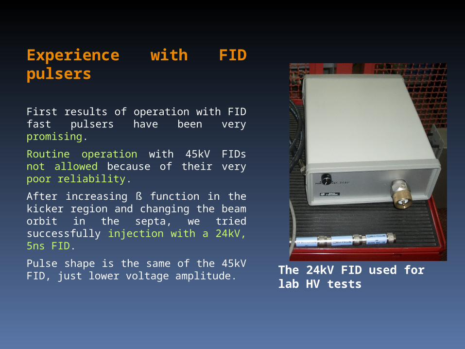
Experience with FID pulsers
First results of operation with FID fast pulsers have been very promising.
Routine operation with 45kV FIDs not allowed because of their very poor reliability.
After increasing ß function in the kicker region and changing the beam orbit in the septa, we tried successfully injection with a 24kV, 5ns FID.
Pulse shape is the same of the 45kV FID, just lower voltage amplitude.
The 24kV FID used for lab HV tests
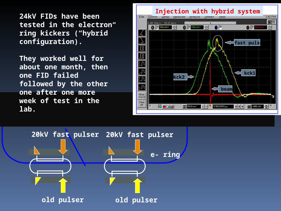
e- ring
old pulser
20kV fast pulser 20kV fast pulser
old pulser
24kV FIDs have been tested in the electron ring kickers (“hybrid” configuration).
They worked well for about one month, then one FID failed followed by the other one after one more week of test in the lab.
kck1 kck2
beam
fast pulse
Injection with hybrid system
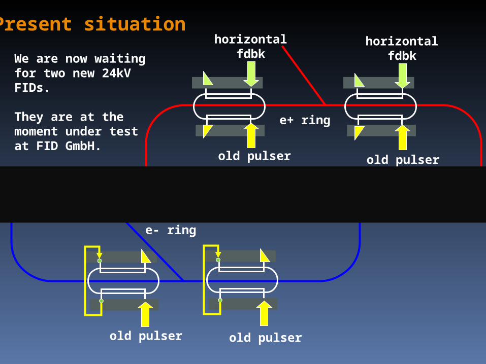
Present situation
e- ring
old pulserold pulser
old pulser old pulser
horizontalfdbk
horizontalfdbk
e+ ring
We are now waiting for two new 24kV FIDs.
They are at the moment under test at FID GmbH.
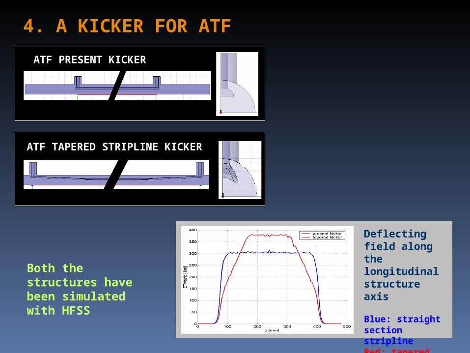
4. A KICKER FOR ATF
ATF PRESENT KICKER
ATF TAPERED STRIPLINE KICKER
Both the structures have been simulated with HFSS
Deflecting field along the longitudinal structure axis
Blue: straight section striplineRed: tapered stripline
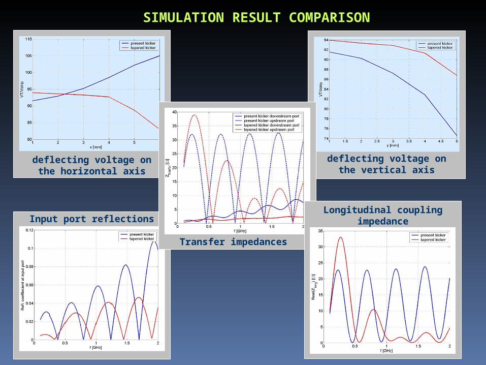
deflecting voltage on the vertical axis
deflecting voltage on the horizontal axis
SIMULATION RESULT COMPARISON
Input port reflections
Transfer impedances
Longitudinal coupling impedance
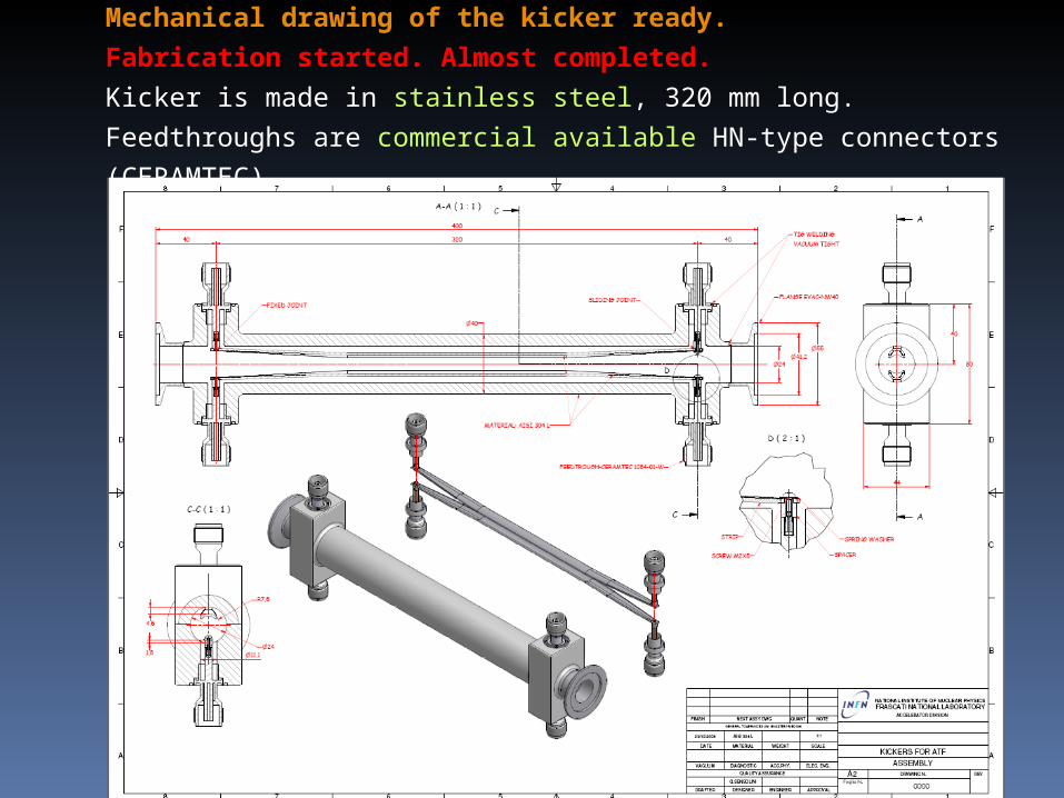
Mechanical drawing of the kicker ready.
Fabrication started. Almost completed.
Kicker is made in stainless steel, 320 mm long.
Feedthroughs are commercial available HN-type connectors (CERAMTEC).
CONCLUSIONS
• The new DAFNE injection kickers, installed one year ago, work well and are very versatile devices. Used with both FID and old DAFNE pulsers and even as a feedback kicker!
• Reliability problems of the fast pulse generators by FID remain to be solved, we hope with the 24kV units.
• A tapered stripline kicker has been designed for ATF, mechanical drawings already done. Ready to be realized.
• A new shielded bellows designed for the DAFNE upgrade as well. It could be easily readapted to different chamber cross sections and a version with cooling is also available.
• Together with the new injection kicker, it contributed to lower the machine impedance, as bunch length measurements have shown.