STRIPING OPERATIONS
32
15 MINUTES or LESS LAYOUT 6 7 STRIPING OPERATIONS TWO LANE TWO WAY ROAD NOTES: 1. All vehicles shall display two 360-degree yellow flashing vehicle lights or strobes. 2. The separation distance between the striper and the last shadow vehicle should be determined by the track free time of the pavement marking material. 3. Any vehicle(s) operated totally or partially in a high speed traffic lane should be equipped with a truck mounted attenuator. 4. If tracking of the wet paint is anticipated, the use of cones or stationary “Wet Paint” signs should be considered. Shadow Vehicle Striper Optional Vehicle W ET PAINT W ET PAINT LINES KEEP OFF All optional vehicles shall have the same signing as the striper. WET PAINT WET YELLOW WET WHITE or or Select appropriate message Select appropriate message W ET PAINT LINES KEEP OFF WET PAINT WET YELLOW WET WHITE or or FRONT FACING SIGNS REAR FACING SIGNS W ET PAINT OPTIONAL or WET PAINT WET PAINT KEEP OFF KEEP OFF and 6K-67
Transcript of STRIPING OPERATIONS

15 MINUTES or LESS LAYOUT 67
STRIPING OPERATIONSTWO LANE TWO WAY ROAD
NOTES:1. All vehicles shall display two 360-degree yellow flashing
vehicle lights or strobes.2. The separation distance between the striper and the last
shadow vehicle should be determined by the track free timeof the pavement marking material.
3. Any vehicle(s) operated totally or partially in a high speedtraffic lane should be equipped with a truck mountedattenuator.
4. If tracking of the wet paint is anticipated, the use of conesor stationary “Wet Paint” signs should be considered.
ShadowVehicle
Striper
OptionalVehicle
WETPAINT W ET PA I N T
L I N E SKE EP O FF
All optional vehiclesshall have the samesigning as the striper.
WET PA I N T
W ET Y E L L OW
WET WH I T E
or
or
Selectappropriate
message
Selectappropriate
message
W ET PA I N T
L I N E SKE EP O FF
WET PA I N T
W ET Y E L L OW
WET WH I T E
or
or
FRONT FACINGSIGNS
REAR FACINGSIGNS
WETPAINT
OPTIONAL
orWET
PAINT
WET
PAINT
KEEP
OFF
KEEP
OFF
and
6K-67

15 MINUTES or LESS LAYOUT 68
STRIPING OPERATIONSTWO LANE TWO WAY ROAD - PASSING ON SHOULDER
NOTES:1. All vehicles shall display two 360-degree yellow flashing
vehicle lights or strobes.2. The separation distance between the striper and the last
shadow vehicle should be determined by the track free timeof the pavement marking material.
3. Any vehicle(s) operated totally or partially in a high speedtraffic lane should be equipped with a truck mountedattenuator.
4. If tracking of the wet paint is anticipated, the use of conesor stationary “Wet Paint” signs should be considered.
ShadowVehicle
Striper
OptionalVehicle
or
WETPAINT W ET PA I N T
L I N E SKE EP O FF
All optional vehiclesshall have the samesigning as the striper.
WET PA I N T
W ET Y E L L OW
WET WH I T E
or
or
Selectappropriate
message
W ET PA I N T
L I N E SKE EP O FF
WET PA I N T
W ET Y E L L OW
WET WH I T E
or
or
FRONT FACINGSIGNS
REAR FACINGSIGNS
WETPAINT
OPTIONAL
10 footMinimum width
WET
PAINT
WET
PAINT
PASS ON
SHOULDER
PASS ON
SHOULDER
and
6K-68

15 MINUTES or LESS LAYOUT 69
STRIPING OPERATIONSCENTERLINE - LANE LINE - EDGELINE STRIPING
FOUR LANE UNDIVIDED ROAD
NOTES:1. All vehicles shall display two 360-degree yellow flashing
vehicle lights or strobes.2. The separation distance between the striper and the last
shadow vehicle should be determined by the track free timeof the pavement marking material.
3. Any vehicle(s) operated totally or partially in a high speedtraffic lane should be equipped with a truck mountedattenuator.
4. If tracking of the wet paint is anticipated, the use of conesor stationary “Wet Paint” signs should be considered.
5. Remove sign when operating this vehicle in the right lane.
WETPAINT
W ET PA I N T
L I N E SKE EP O FF
All optional vehiclesshall have the samesigning as the striper.
WET PA I N T
W ET Y E L L OW
or
FRONT FACINGSIGNS
REAR FACINGSIGNS
Selectappropriate
message
ShadowVehicle
Striper
OptionalVehicle
or
Selectappropriate
message
W ET PA I N T
L I N E SKE EP O FF
WET PA I N T
W ET Y E L L OW
WET WH I T E
or
or
5
LANE
CLOSED
LANE
CLOSED
NEXT
1/2 MILE
NEXT
1/2 MILE
and
6K-69

15 MINUTES or LESS LAYOUT 70
STRIPING OPERATIONSLANE LINE STRIPING - CENTER LANE OPERATIONS
MULTI-LANE DIVIDED ROAD
NOTES:1. All vehicles shall display two 360-degree yellow flashing
vehicle lights or strobes.2. The separation distance between the striper and the last
shadow vehicle should be determined by the track free timeof the pavement marking material.
3. Any vehicle(s) operated totally or partially in a high speedtraffic lane should be equipped with a truck mountedattenuator.
4. If tracking of the wet paint is anticipated, the use of conesor stationary “Wet Paint” signs should be considered.
W ET PA I N T
L I N E SKE EP O FF
All optional vehiclesshall have the samesigning as the striper.
WET PA I N T
W ET PA I N T
REAR FACINGSIGNS
W ET PA I N T
L I N E SKE EP O FF
ShadowVehicle
Striper
OptionalVehicle
or or
orLANE
CLOSED
LANE
CLOSED
NEXT
1/2 MILE
NEXT
1/2 MILE
and
6K-70

15 MINUTES or LESS LAYOUT 71
WORK OFF ROADWAYMOBILE OPERATIONS HAVING LITTLEOR NO INTERFERENCE WITH TRAFFIC
NOTES:1. The operations should be scheduled and completed during daylight work shifts
and have little or no interference with traffic. The work should be suspendedduring periods of poor weather or visibility.
2. All vehicles shall be equipped with a flashing vehicle light visible360-degrees around the vehicle when viewed from a distance of 60 feet.
when there is an adequateapproach decision sight distance to the equipment along the majority of theroute
3. The ROAD WORK AHEAD sign may be omitted
.4. When advance warning signs are used, the signs should be no more than
3 miles from the work vehicle. The location of the signs should be determinedby the sources of traffic, such as major cross roads.
5. On roadways where decision sight distance is restricted and the equipmentmust encroach into the traffic lane routinely, a shadow vehicle may beused as shown.
3
4
1 2
5
required for all slowmoving vehiclesoperating onpublic roadways
SEENOTE 5
SEENOTE 5
OptionalShadowVehicle
OPTIONAL
F
6K-71

15 MINUTES or LESS LAYOUT 72
GRAVEL ROAD MAINTENANCEGRADING OPERATIONSTWO LANE TWO WAY ROAD
5
NOTES:1. Grading operations should be scheduled and completed during daylight work
shifts. Work should be suspended during poor weather or visibility conditions.2. Motor Graders shall be equipped with a flashing vehicle light visible
360 degrees around the vehicle when viewed from a distance of 60 feet.3. Motor grader blade end(s) may be marked with red or orange flags to provide
additional warning and make the equipment more visible to passing vehicles.when there is an adequate
approach decision sight distance to the motor grader along the majority of theroute
4. The ROAD WORK AHEAD signs may be omitted
.5. When advance warning signs are used, the signs should be no more than
3 miles from the work vehicle. The location of the signs should be determinedby the sources of traffic, such as major cross roads.
4
4
required for all slowmoving vehiclesoperating onpublic roadways
A
6K-72

3 DAYS or LESS LAYOUT 73
TYPICAL BUMP SIGNING
For multi-lane dividedor one-way road only
For multi-lane dividedor one-way road only(optional on two-lane,
two way road)
For two-lanetwo-way road
For two-lanetwo-way road
XX
XXXXXX
XXXX
5feet
5feet
NOTES:1. When used, Advisory Speed plaques shall be installed below the
appropriate warnings.2. These devices may be omitted when the posted speed limit is
40 mph or less.
1
1
1
1
1
1
2
22
B U M P
B U M PBUMP
6K-73

RE-SURFACING OPERATIONWORK SPACE BEFORE AND THRU INTERSECTION
MULTI-LANE DIVIDED ROAD
3 DAYS or LESS LAYOUT 74
NOTES:1. When used, Advisory Speed plaques shall be installed below
the appropriate warnings.2. Use the same advance warning signs and spacings for the other
approach to the milled roadway surface area.3. The BUMP AHEAD and Advisory Speed plaque may be omitted
when the posted speed is 40 mph or less.4. Use the appropriate advance warning sign for the roadway
condition, i.e. GROOVED PAVEMENT, LOOSE GRAVEL,ROUGH ROAD, STEEL PLATE AHEAD. A Motorcycle plaque maybe installed below the appropriate advance warning sign if the warningis directed primarily to motorcyclists.
XX
XX
RO U G HROAD
XX
RO U G HROAD
XX
RO U G HROAD
XX
ROUGHROAD
1
1
1
1
1
1
4
4
4
4
1
2
1
3
3
3
XX
B U M P
XX
B U M P
XX
BUMP
BUMP
BUMP
BUMP
BUMP
6K-74

BLASTING ZONE
3 DAYS or LESS LAYOUT 75
300 - 500feet
1000feet
BLASTINGZONE
1000feet
300 - 500feet
NOTES:1. Whenever electric blasting caps are used for blasting within 1000 feet of a
roadway, the signing shown shall be used. On a divided highway, the signsshould be installed on both sides of the directional roadways.
2. The signs shall be covered or removed when there are no explosives in the areaor the area is otherwise secure.
3. Any intersecting road within the 1000-foot radius of the blasting area shall besigned in a similar manner.
4. Prior to blasting, the blaster in charge shall determine whether highway trafficin the blasting zone will be endangered by the blasting operation. If there isdanger, highway traffic will not be permitted to pass through the blasting zoneduring blasting operations. See Layouts 81, 82, or 83.
1000foot
Radius
1000foot
Radius
T U R N O F F2-WAY RAD I O
A N D
C E L L P H O N E
TURNOFF2-WAYRADIO
AND
CELLPHONE
6K-75

3 DAYS or LESS LAYOUT 76
CROSSROAD & CONFIRMATION SIGNINGTRAFFIC CONTROL ZONE
NOTES:1. This layout should be used for those stationary temporary traffic
control zones that extend over a relatively long segment of roadway.2. The appropriate layout shall be used for the active work space
(such as area of paving, etc).3. Confirmation signing for a continuous condition should be placed
at approximately 1 mile spacing.4. Use the appropriate advance warning sign for the roadway condition,
i.e. GROOVED PAVEMENT, LOOSE GRAVEL, ROUGH ROADSTEEL PLATE AHEAD.A Motorcycle plaque may be installed below the appropriate advancewarning sign if the warning is directed primarily to motorcyclists.
ROAD
WORK
AHEAD
ROAD
WO R K
AH EAD
ROAD
WORK
AHEAD
ROAD
WORK
AHEAD
ROAD
WORK
AHEAD
ROAD
WORK
AHEAD
LOW LOW
SHOULDER
LOWLOW
S H O U LD ER
LOWLOW
S H O U LD ER
LOWLOW
S H O U LD ER
LOW LOW
SHOULDER
LOWLOW
S H O U LD ER
LOW LOW
SHOULDER
LOW LOW
SHOULDER
A
A
A
A
A
A
A
A
A
A
1 mileMaximum 1 mile
Maximum
4
4
4
4
4
4
4
4
6K-76

ADVISORY SPEED LIMITMULTI-LANE ROAD
A
A
Notes:1. Use the appropriate layout for channelizing, advance signing, and spacing.2. In long work zones, this sign assembly may be repeated before each worker
area. When used, it shall be installed less than one mile in advance of the workers.3. If used, an Advisory Speed Limit plaque shall be installed beneath the Worker
Ahead symbol sign or the appropriate advance warning sign(s).4. The advisory speed value shall not be higher than any inplace regulatory speed
limit.5. An advance warning sign with an Advisory Speed Limit plaque should not be
placed near a regulatory speed sign.6. See “ ” for more information on work zone
speed limits.Work Zone Speed Limit Guidelines
12 HOURS or LESS LAYOUT 77
XX
XX
1
3
3
2
6K-77
A/2
A/2
12 HOURS or LESS LAYOUT 78
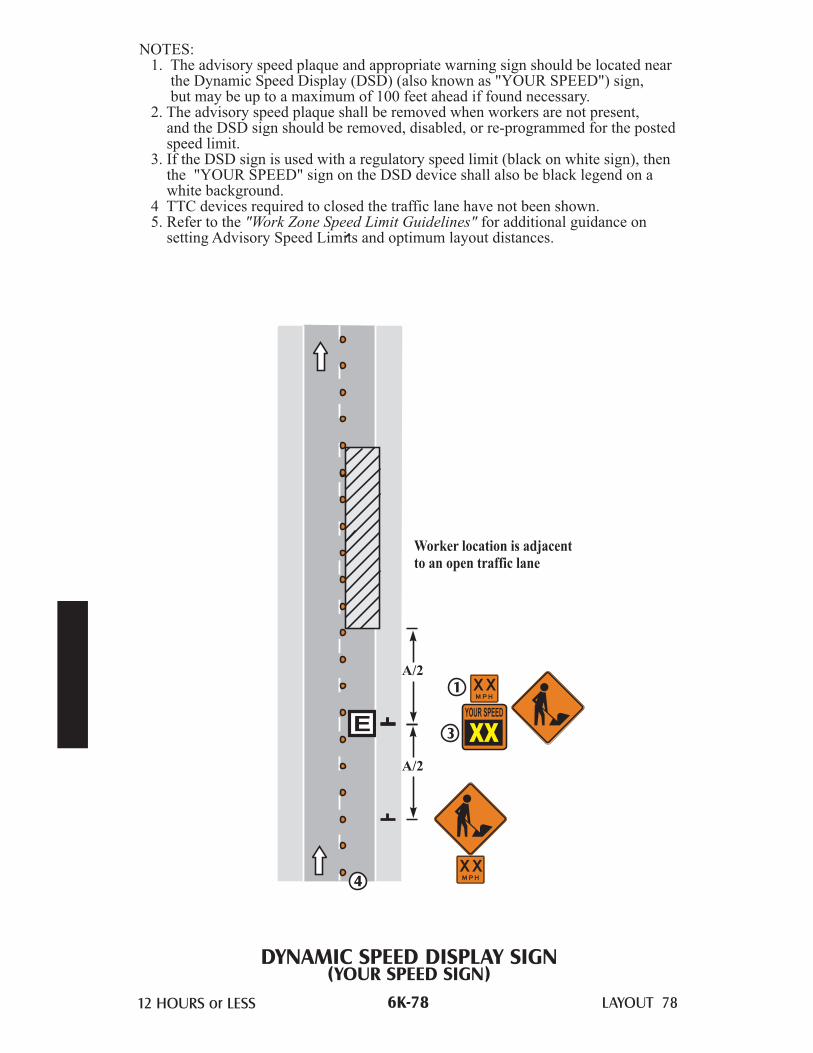
DYNAMIC SPEED DISPLAY SIGN(YOUR SPEED SIGN)
Worker location is adjacentto an open traffic lane
NOTES:1. The advisory speed plaque and appropriate warning sign should be located near
the Dynamic Speed Display (DSD) (also known as "YOUR SPEED") sign,but may be up to a maximum of 100 feet ahead if found necessary.
2. The advisory speed plaque shall be removed when workers are not present,and the DSD sign should be removed, disabled, or re-programmed for the postedspeed limit.
3. If the DSD sign is used with a regulatory speed limit (black on white sign), thenthe "YOUR SPEED" sign on the DSD device shall also be black legend on awhite background.
4 TTC devices required to closed the traffic lane have not been shown.5. Refer to the for additional guidance on
setting Advisory Speed Limits and optimum layout distances."Work Zone Speed Limit Guidelines"
3
1
4XXM P H
XXM P H
6K-78

This page has been intentionally left blank.
.

3 DAYS or LESS LAYOUT 79a & b
STOPPED TRAFFIC AHEAD WARNING SYSTEMLayout 79a
NOTES:1. The layout only shows the additional signs and devices required to setup a
Stopped Traffic System. See other Temporary Traffic Control layouts for theproper temporary traffic control devices beyond the ROAD WORK AHEADsigns.
2 . The STOPPED TRAFFIC WHEN FLASHING signs or the PCMS shouldactivate and deactivate when the downstream detector senses average trafficspeeds meeting threshold values as set by the engineer. A maximum one minuteaverage speed drop of 20 mph or more below the posted speed limit (postedprior to road work in the queue area) may typically be used for a threshold valueon high speed roadways. To deactivate the signage, the maximum one minuteaverage speed typically should recover to within 10 mph of the posted speedlimit or higher.
3. The estimated maximum queue length may be determined by engineeringanalysis or previous experience, and should be reviewed and field adjusted to fitactual traffic conditions such that the first warning device is upstream of thequeue.
4. When PCMS devices are used, the two part message should read: STOPPEDTRAFFIC - - PREPARE TO STOP and the PCMS may be used for otherappropriate messages whenever the stopped traffic message is not required.
6K-79a

3 DAYS or LESS LAYOUT 79a & b
STOPPED TRAFFIC AHEAD WARNING SYSTEMLayout 79b
3
4
4
4
4
WORK AREA andADVANCE SIGNINGas required
One milespacing
One milespacing
One milespacing
A
Detector Location for warningsign one mile upstream
Detector Location for warningsign one mile upstream
Detector Location for warningsign one mile upstream
Detector Location for warningsign one mile upstream
or
Continue spacing toextend beyond anticipated
maximum queue length
STO P P EDTRAFF I CWH E N F LA S H I N G
orSTO P P EDTRAFF I CWH E N F LA S H I N G
orSTO P P EDTRAFF I CWH E N F LA S H I N G
orSTO P P EDTRAFF I CWH E N F LA S H I N G
R OAD
WO R K
AH EAD
ROAD
WO R K
AH EAD
6K-79b

3 DAYS or LESS LAYOUT 80
ROAD CLOSURE
NOTES:1. The Road Authority will determine if a detour is required and specify the
detour route.2. Road Closure Notice sign should be installed seven days in advance of the
closure.3. Install at the last driveway or intersection beyond which there is no public access.
ROADCLOS ED
3
2
A
A
A
B
ROAD CLOS ED1 0 M I L E S AH EADLOCAL TRAFF I C O N LY
ROAD CLOS ED
TH R U TRAFF I CTO
or
Use when it is 2 miles orgreater to the road closure
Minor Roador Driveway
ROAD
CLOS ED
B EG I N N I N G
XXXX XX
XXX
FE ET
6K-80

TEMPORARY ROAD CLOSURETWO LANE TWO WAY ROAD
15 MINUTES or LESS LAYOUT 81
50 feet
50 feet
A
A
A
A
A
A
NOTES:1. The traffic from both lanes should not be stopped for more than
15 minutes.2. Conditions represented are for work during daytime hours only.3. For night closures, the following should be used:
a. Law enforcement officers with squad car for flaggers.b. A changeable message sign in each direction.
4. The BE PREPARED TO STOP sign may be omitted when the postedspeed limit is 40 mph or less.
4
4
6K-81

TEMPORARY ROAD CLOSUREMULTI-LANE UNDIVIDED ROAD
15 MINUTES or LESS LAYOUT 82
NOTES:1. The traffic from both lanes should not be stopped for more than 15 minutes.2.
3.
4. A law enforcement officer with squad car shall be used instead of a flaggerduring night operations.
5. Advance traffic control devices for a left lane closure shall be as shown inLayouts 34 or 35.
6. The advance warning sign sequence is shown for one way direction only.The other direction shall be identical.
The BE PREPARED TO STOP sign and the flashing arrow board shall beused when the posted speed limit is 45 mph or greater.For roads with 3 or more lanes of traffic in one direction, use theappropriate stationary layout.
4
22
5 6
50 feet
AMinimum
5
2
or
6K-82

TEMPORARY ROAD CLOSUREMULTI-LANE DIVIDED ROAD
15 MINUTES or LESS LAYOUT 83
NOTES:1. The traffic from both lanes should not be stopped for more than 15 minutes.2.
3.
4. A law enforcement officer with squad car shall be used instead of a flaggerduring night operations.
5. Advance traffic control devices for a left lane closure shall be as shown inLayout 52.
The BE PREPARED TO STOP sign and the flashing arrow board shall beused when the posted speed limit is 45 mph or greater.For roads with 3 or more lanes of traffic in one direction, use theappropriate stationary layout.
50 feet
AMinimum
5
4
22
2
or
6K-83

3 DAYS or LESS LAYOUT 84a & b
CROSSWALK CLOSURES AND PEDESTRIAN DETOURSLAYOUT 84a
NOTES:1. When crosswalks, sidewalks or other pedestrian facilities are blocked, closed or
relocated, temporary facilities shall include accessibility features consistent withthe features present in the existing pedestrian facility.
2. The examples show only key typical dimensions. Refer to the MnDOT Pedestrian Accommodations Through Work Zones website(http://www.dot.state.mn.us/trafficeng/workzone/apr.html) for standards, guidance and options when blocking, closing, or relocating pedestrian facilities.
3. Only traffic control devices controlling pedestrian flows are shown. Otherdevices may be needed to control traffic on the streets.
4. An approved audible message device or tactile message should be providedfor sight-impaired pedestrians. When used, a message device should provide acomplete physical description of the temporary pedestrian detour includingduration, length of (and/or distance to) the by-pass, any restrictions or hazardsand project information as listed in note 5 below. The number and location ofdevices should be determined for each project prior to starting work. Devicesmay be placed prior to sidewalk work to warn regular users of the planned work.
5. Typical sign message for a temporary pedestrian detour should includeinformation such as the duration of the walkway restrictions (beginning and/orend dates) and a project contact number for 24/7 questions or reporting hazards.
6. The International Symbol of Accessibility should be displayed when anywalkway through a work zone has been determined to be TPAR compliant.The Symbol of Accessibility shall not be displayed if persons with disabilitiesshould not use the primary temporary pedestrian detour. The reason for thenon-compliance should be posted and an alternate route should be posted whenthe primary temporary pedestrian detour is non-complaint to TPAR standards.
7. Conditions that are beyond recommended standards should be documented.A walkway is non-compliant if it is missing key ADA elements such as curbramp(s), truncated domes, and detectable edging. Other restrictions or hazardsmay include insufficient width or pinch-point widths, traffic conflicts, steepgrades, non-continuous railings, tripping hazards, or uneven/rough/soft surfaceconditions, etc.
8. Pedestrian traffic signal displays controlling closed crosswalks shall be covered.
9. Pedestrian detour trailblazing signs should be used if the pedestrian detour islocated someplace other than across the street from the sidewalk closure.
6K-84a

3 DAYS or LESS LAYOUT 84a & b
CROSSWALK CLOSURES AND PEDESTRIAN DETOURSLAYOUT 84b
SIDEWALKCLOSED
USEOTHERSIDE
SIDEWALKCLOSED
USEOTHERSIDE
SIDEWALK
CLOSED
SIDEWALK
CLOSED
S I D EWAL K
C L O S E D
SIDEWALK
CLOSED
ES
T.CO
MP
LE
TIO
NO
CT
20XX
PR
OJE
CT
CO
NTA
CT
612-XX
X-X
XX
EST.COMPLETIONOCT20XX
PROJECTCONTACT612-XXX-XXX
E N D S O CT 2 0 X X
C O N TA CT 6 1 2 -X X X-X X X46 5
ENDSOCT20XX
CONTACT61 2-XXX-XXX
4
6
5
4
4
6
6
5
5
S I D EWA L K C L O S E D
AH EAD
C RO S S H E R E
SIDEWALKCLOSED
AHEAD
CROSSHERE
6K-84b

3 DAYS or LESS LAYOUT 85a & b
SIDEWALK BY-PASSLAYOUT 85a
NOTES:1. When crosswalks, sidewalks or other pedestrian facilities are blocked, closed or
relocated, temporary facilities shall include accessibility features consistent withthe features present in the existing pedestrian facility.
2. The examples show only key typical dimensions. Refer to the MnDOT Pedestrian Accommodations Through Work Zones website(http://www.dot.state.mn.us/trafficeng/workzone/apr.html) for standards, guidance and options when blocking, closing, or relocating pedestrian facilities.
3. Where high speeds and/or high traffic volumes are anticipated, barrier shouldbe used to separate the temporary pedestrian walkway from vehicular traffic.When used, barriers shall be installed as detailed in the MN MUTCD Part 6F.
4. Only traffic control devices controlling pedestrian flows are shown.Other devices may be needed to control traffic on the streets.
5. When both sides of a temporary pedestrian bypass require channelizingdevices, then the devices should be a similar type (railing system, barricade,or fencing system), excluding when a barrier (such as concrete barrier) isused to protect pedestrians from an open traffic lane.
6. An approved audible message device or tactile message should be provided forsight-impaired pedestrians. When used, a message device should provide acomplete physical description of the temporary pedestrian by-pass includingduration, length of (and/or distance to) the bypass, any restrictions or hazardsand project information as listed in note 7 below. The message device(s) mayalso describe an alternate route. The number and location of devices should bedetermined for each project prior to starting work. Devices may be placed priorto sidewalk work to warn regular users of the planned work.
7. Typical sign message for a temporary pedestrian bypass should includeinformation such as the duration of the walkway restrictions (beginning and/orend dates) and a project contact number for 24/7 questions or reporting hazards.
8. The International Symbol of Accessibility should be displayed when anywalkway through a work zone has been determined to be TPAR compliant.The Symbol of Accessibility shall not be displayed if persons with disabilitiesshould not enter the temporary pedestrian by-pass. An alternate route should beposted when the temporary pedestrian bypass is non-complaint to TPARstandards.
9. Conditions that are beyond recommended standards should be documented.A walkway is non-compliant if it is missing key ADA elements such as curbramp(s), truncated domes, and detectable edging. Other restrictions or hazardsmay include insufficient width or pinch-point widths, traffic conflicts, steepgrades, non-continuous railings, tripping hazards, or uneven/rough/soft surfaceconditions, etc.
10. When a sidewalk is closed but workers are present who will provide assistanceor directions to pedestrians, then the devices as shown are not required.
6K-85a

3 DAYS or LESS LAYOUT 85a & b
SIDEWALK BY-PASSLAYOUT 85b
MINOR ROAD
Curb & gutter or other transitionbetween roadway and sidewalk
TPAR width of 60 inches is preferred.If width is 48 inches, then at least one60 x 60 inch passing space is requiredfor every 200 feet of length.
TPAR width of 60 inches is preferred.If width is 48 inches, then at least one60 x 60 inch passing space is requiredfor every 200 feet of length.
Temporary walkway surface coveringrough, soft or uneven ground or hazards
Additional audible message devicesmay be needed for route information
Temporary curb ramp providing 12:1 (8%)slope or flatter and non-slip treatment added
Temporary curb ramp providing12:1 (8%) slope or flatter andnon-slip treatment added
Ramp landing area providing48 x 48 inch minimum area and 2% orflatter cross-slope
Ramp landing area providing a 48 x 48 inchminimum area and 2% or flatter cross-slope
A barrier with taper andattenuation (length as required)
Temporary truncated domes, optionalbased upon usage of cross-street
5 device taper 25 feet long (1 stall),recommended when the closed area wasused as an intermittent traffic lane orbypass lane.
LOW-SPEED ROADWAY
HIGH-SPEED ROADWAYor
LOW-SPEED MULTI-LANE
5
5
S I D EWALK
WO R K AH EAD
E N D S O CT 2 0 X X
C O N TA CT 6 1 2 -X X X-X X X6
78
S I D EWALK
WO R K AH EAD
E N D S O CT 2 0 X X
C O N TA CT 6 1 2 -X X X-X X X6
78
6K-85b

3 DAYS or LESS LAYOUT 86a & b
FLAGGING CROSSROADS AND BLIND CURVESPILOT CAR OPERATIONS
LAYOUT 86a
NOTE:1. Approach signs are the same in both directions.2. Full flagging station signing and pilot car turn-around areas shall be located
at both ends of the work area.3. When a flagger is positioned at a low volume intersection, they:
• shall have 2-way radio communications with the pilot car; and• may need additional flaggers to direct traffic when the crossroad
consistently has multiple vehicles per direction waiting each pilot car cycle.4. A flagger may be placed at a blind curve, crest of a hill or other site
obstruction where traffic might enter from other driveways or entrances towarn the pilot car that there may be oncoming traffic.When used, the flagger:• shall be located to clearly see traffic from both directions;• shall not be positioned in the open traffic lane;• shall have 2-way radio communications with the pilot car;• shall have a flagger paddle; and• should have a means to warn an errant driver such as a air horn.
5. This sign may be used in work areas where pilot car brochures have beendistributed to the local residents and businesses.
6. This sign shall be mounted on the pilot car.7. Channelizers shall be placed near intersections and flagging stations.8. Channelizers are optional with pilot car operations.9. The two-way taper should be 50 feet using 5 equally spaced channelizing
devices.
6K-86a

3 DAYS or LESS LAYOUT 86a & b
FLAGGING CROSSROAD AND BLIND CURVESPILOT CAR OPERATIONS
LAYOUT 86b
STOP
STOP
STOP
STOP
P I LO T CAR
FO L LOW M E
Low Volume
Road
Local AccessRoad
Blind Curveor
Crest of Hill
8
6
5
54
9
7
73
1 2
1 2
6K-86b

This page has been intentionally left blank.
.

3 DAYS or LESS LAYOUT 87
2G
Portablerumble strips
B
NOTE:1. Approach signs are the same in both directions.2. The flagger may be equipped with an airhorn.3. The STOP/SLOW paddle may have flashing conspicuity lights on the signs.4. The Flagger Ahead sign may have flashing conspicuity lights on it.5.
The centerline channelizers are optional with pilot car operations.8. The portable rumble strips shall be spaced according to the manufacturer’s
recommendations or typical 4 foot on center.
Type A channelizing devices such as weighted channelizers, cones, tubularmarkers, or centerline delineators.
6. The two-way taper should be 50 feet using 5 equally spaced channelizingdevices.
7.
6
7
FLAGGING STATION OPTIONSTWO-LANE TWO-WAY ROAD
50 feet
or
G12 x 18inches
OPTIONAL
5
OPTIONAL
2 3
OPTIONAL
OPTIONAL
4
1
6K-87

3 DAYS or LESS LAYOUT 88a & b
LANE CLOSURE IN ROUNDABOUTSINGLE LANE ROUNDABOUT
LAYOUT 88a
NOTES:
1.
The two-way taper should be 50 feet using 5 equally spaced channelizing
devices.
Each roundabout is unique and the traffic control shall be developed to
meet the specific conditions of the location and the work operation.
A detour could better serve traffic movement and shall be considered as an
alternative to the flagger operation.
2. Flagging operations may not be necessary when working on the shoulders
or in the island of the roundabout. If a driving lane(s) width of at least
10 feet (or more) can be maintained while shoulder work on an approach
is being conducted, the driving lane(s) may remain open to traffic.
3. Approach signs are the same in all directions.
4. Flaggers shall control traffic flow on all approaches of the one-lane
roundabout.
5. A lead flagger shall be designated and radio communication shall be used
by the flaggers.
6. Only one approach of traffic shall be released at a time.
7. At night, flagger stations shall be illuminated. Street lights and vehicle
headlights shall not be used to illuminate the flagger station.
8. Type B channelizers may be used.
9. A PCMS sign should be considered as part of this operation to provide
clear guidance to motorists on all approaches of the roundabout, especially
approaches that must reverse traffic flow.
10.
6K-88a

3 DAYS or LESS LAYOUT 88a & b
LANE CLOSURE IN ROUNDABOUTSINGLE LANE ROUNDABOUT
LAYOUT 88b
G
��������������������������������������������������������������������������������������������������������������������������������������������������������������������������������������������������������������������������������������������������������������������������������������������������������������������������������������������������������������������������������������������������������������������������������������������������������������������������������������������������������������������������������������������������������������������������������������������������������������������������������������������������������������������
variable
3
3
10
10
10
10
10
10 10
3
OPTIONAL
ON E LANE
R OAD
AH EAD
6K-88b

This page has been intentionally left blank.
.

3 DAYS or LESS LAYOUT 89
LEFT LANE CLOSURE IN ROUNDABOUTTWO LANE ROUNDABOUT
or
or
variable
G
25 feet
2
3 3
3
3
5
OPTIONAL
��������������������������������������������������������������������������������������������������������������������������������������������������������������������������������������������������������������������������������������������������������������������������������������������������������������������������������������������������������������������������������������������������������������������������������������������������������������������������������������������������������������������������������������������������������������������������������������������������������������������������������������������������������������������������������������������������������������������������������������������������������������������������������������������������������������������������������������������������������������������������������������������������������������������������������������������������������������������������������������������������������������������������� � � � � � � � � � � � � � � � �
2
2
NOTES:1. Each roundabout is unique and the traffic control shall be developed to
meet the specific conditions of the location and the work operation.A detour could better serve traffic movement and shall be considered as analternative to the flagger operation.
2. Approach signs are the same in all directions.3. On divided highways having a median wider than 8 feet, right and left
sign assemblies shall be required.4. Type B channelizers may be used.5. The flashing arrow board shall be used when the posted speed limit is
45 mph or greater.
4
6K-89

3 DAYS or LESS LAYOUT 90
RIGHT LANE CLOSURE IN ROUNDABOUTTWO LANE ROUNDABOUT
��������������������������������������������������������������������������������������������������������������������������������������������������������������������������������������������������������������������������������������������������������������������������������������������������������������������������������������������������������������������������������������������������������������������������������������������������������������������������������������������������������������������������������������������������������������������������������������������������������������������������������������������������������������������������������������������������������������������������������������������������������������������������������������������������������������������������������������������������������������������������������������������������������������������������������������������������������������������������������������������������������������������������� � � � � � � � � � � � � � � � �
�������
�������
�������
or
or
variable
100feet
G
2
66
6
6
2
3 3
4
3
3
5
OPTIONAL
OPTIONAL
2
NOTES:1. Each roundabout is unique and the traffic control shall be developed to
meet the specific conditions of the location and the work operation.A detour could better serve traffic movement and shall be considered as analternative to the flagger operation.
2. Approach signs and devices are the same in all directions.3. On divided highways having a median wider than 8 feet, right and left
sign assemblies shall be required.4. Type B channelizers may be used.5. The flashing arrow board shall be used when the posted speed limit is
45 mph or greater.6. The distance between channelizing devices should be 10 feet or adjusted
for local conditions.
6K-90