STRESSES - NASA · PDF filepublication entitled "Stress Analysis of Circular Semimonocoque...
28
NASA TM X-1354 ~ STRESSES IN A COMPRESSIVELY LOADED CIRCULAR SEMIMONOCOQUE CYLINDER WITH A CUTOUT By R. E. Martin Manned Spacecraft Center Houston, Texas NATIONAL AERONAUT ICs AN D SPACE ADMINISTRATION For sale by the Clearinghouse for Federol Scientific and Technical lnformotion Springfield, Virginia 22151 - CFSTI price $3.00 https://ntrs.nasa.gov/search.jsp?R=19670009363 2018-05-13T00:47:22+00:00Z
Transcript of STRESSES - NASA · PDF filepublication entitled "Stress Analysis of Circular Semimonocoque...

NASA TM X-1354 ~
STRESSES IN A COMPRESSIVELY LOADED CIRCULAR
SEMIMONOCOQUE CYLINDER WITH A CUTOUT
By R. E. Martin
Manned Spacecraft Cen te r Houston, Texas
NATIONAL AERONAUT ICs AN D SPACE ADMINISTRATION
For sale by the Clearinghouse for Federol Scientific and Technical lnformotion Springfield, Virginia 22151 - CFSTI price $3.00
https://ntrs.nasa.gov/search.jsp?R=19670009363 2018-05-13T00:47:22+00:00Z

ABSTRACT
The results of an experimental program to determine the stresses in a stiffened cylinder with a cutout and the cylinder loaded in axial compression are presented in this document. Three cutout sizes were considered in the program, and stringer loads and skin panel shear flows are presented in graphic form for the three sizes. One test cylinder was used for all cutout cases, and the cutout size was succes- sively enlarged. Strain measurements were made with resistor-type strain gages on the skin panels and stringers. A stress perturbation technique was used to determine the stringer loads and skin panel shear flows. These stringer loads and panel shear flows predicted by this analytical method are com- pared with the experimental results obtained in this program.
ii

STRESSES IN A COMPRESSIVELY LOADED CIRCULAR
SEMIMONOCOQUE CYLINDER WITH A CUTOUT
By R. E. Martin Manned Spacecraft Center
SUMMARY
This paper presents the results of an experimental program to determine the stresses in a stiffened cylinder with a cutout and the cylinder loaded in axial compres- sion. Stringer loads and skin panel shear flows are presented in graphic form for three cases of cutout size. The three cutout sizes considered were: (1) two skin panels and the corresponding stringer removed, (2) three skin panels and the two cor- responding stringers removed, and (3) four skin panels and three stringers removed. One test cylinder was used for all cutout cases, and the cutout size was successively enlarged; the cutouts were made at the longitudinal midpoint of the cylinder and be- tween two adjacent rings. Strain measurements were made with resistance-type strain gages on the skin panels and stringers.
The stringer loads and skin panel shear flows were determined analytically for each of the three cutout cases by the stress perturbation technique described in the publication entitled "Stress Analysis of Circular Semimonocoque Cylinders with Cutouts, " by H. G. McComb, Jr., NACA Report 1251. The stringer loads and panel shear flows, predicted by this analytical method, are compared with the experimen- tal results obtained in this program, and comments are made regarding the use of the method of analysis presented by McComb in his publication.
INTRODUCTION
The designs of many spacecraft and aircraft structures incorporate access openings which are necessary for inspection of internal equipment, fo r connection of ground support equipment to devices inside the vehicle, and for other purposes. Such cutouts cause a redistribution of stress in the structure.
The circular semimonocoque cylinder, a thin-walled circular cylinder stiffened with rings and stringers, is used extensively as the primary structure in both space- craft and aircraft. Several analytical and experimental investigations have been con- ducted to determine the internal stress distribution in this type of stiffened cylindrical shell with a cutout. The analytical investigations (ref. 1) have considered most of the practical loading conditions; however, experimental investigations have been some- what limited. References 2 to 4 give the results of the related experimental work; loading conditions considered a re shear load, pure torsion, and pure bending.

Reference 5 gives a comparison between the analytical results as predicted by the s t ress perturbation technique and the experimental results given in references 2 , to 4.
The test results reported in this paper were obtained from a cylinder subjected to axial compression. A cutout was made in the cylinder, and the size of the cutout was successively increased so that three different cutout sizes could be tested. A comparison of the experimental results with analytical data is presented graphically herein. The information has been presented in accordance with the method which is considered to be the most applicable for the cylinder study as predicted by the stress perturbation technique described in reference 1.
SYMBOLS
effective cross-sectional area of a stringer
actual cross-sectional area of a stringer
arc distance between stringers
Young's modulus of elasticity
shear modulus of elasticity
effective moment of inertia of a ring c ross section
distance between rings
total number of stringers in cylinder
external concentrated force in the longitudinal direction applied to a stringer at its intersection with a ring
basic stringer load in stringer j at ring i
load in stringer j at ring i due to a unit concentrated perturbation load on stringer q at ring 6
load in stringer j at ring i due to a load about shear panel ( 5 , q)

external shear force per unit length applied about a shear panel
shear flow in shear panel (i, j)
basic shear flow in shear panel (i, j)
shear flow in shear panel (i, j) due to a unit shear perturbation load about shear panel (6 , q)
radius to middle surface of sheet
thickness of sheet
thickness of all material carrying bending stresses in cylinder if uni- formly distributed around perimeter, A/b
central angle between stringers, 2n/m
panel shear stress
EXPERIMENTAL PROCEDURE
The test cylinder shown in the diagram in figure 1 was 30 inches in diameter and 113.9 inches long, and was fabricated using 0.040-inch-thick skin, 36 external 1- by 1- by 1/16-inch angle stringers, and 10 equally spaced 3/4- by 2- by 1/16~inch equal-length Z-section rings. The material used for all parts was 2024-T4 aluminum alloy. section, and then machining the Z-section from the rectangle, 12.5 inches was governed by the skin panel which would be typical for this type of structure. The cylinder was assembled using 5/32 -inch-diameter aircraft-type rivets. The assembled cylinder and the test setup are shown in figure 2.
The rings were produced by casting a circular ring with a rectangular cross The ring spacing of
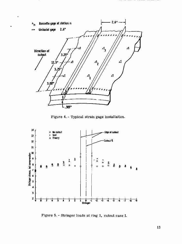
The completed cylinder w a s instrumented with foil-type strain gages on the skin panels and stringers. Rectangular rosettes were used on the skin panels, and uniaxial gages were used on the stringers. All strain gages were applied with contact cement and waterproofed with a protective covering. Starting at stringer number 0 (see fig. 3), 10 skin panels to either side were instrumented with three rosette gages per skin panel. Bays 0, 1, and 2 were instrumented in this manner. Stringers -9 to 0 and 1 to 9 were instrumented with uniaxial gages at the intersections of the stringers with rings .I, 2, and 3. The stringer strain gages were located at the neutral axis of the skin-stringer combination so that only direct s t ress in the stringer was measured; a width of skin equal to the bay width was used in computing the neutral axis. Typi- cal gage installation for both rosettes and uniaxial gages is shown in figure 4.
3

The outputs of the strain gages were recorded on magnetic tape using a 50-channel data acquisition system. on a CDC 3600 computer. Since only 50 channels of data acquisition were available and 597 strain channels were used, it was necessary to load the cylinder and record 50 channels of data, then release the load and connect another 50 channels; the load was reapplied and the data were recorded. This process was repeated until all strain- gage outputs had been recorded for each test condition. The output of two gages was recorded each time the cylinder was loaded. A check on the ability of the loading f ix- ture to produce the same load for each run was provided by having the same two gage outputs recorded for every test run.
The data from the magnetic tapes were reduced -
The test setup for applying the compressive loads is shown in figure 2. The load was applied equally to the three hydraulic cylinders so that a uniformly distri- buted compressive load was, in turn, applied to the cylinder. The loads in all cylinders were controlled by one control console. This central control made it pos- sible to increase the load in each hydraulic cylinder at the same rate. Individual load cells were used to measure the load applied by each of the three hydraulic cylinders. The loading head was designed so that the maximum plate deflection in the direction of the three applied loads was less than 5 X inch, causing the head to remain essen- tially flat when the load was applied through the three points. It w a s necessary for the head to remain flat to insure that the three point loads were uniformly distributed to the cylinder.
The initial test conducted on the cylinder was for the no-cutout condition. The cylinder was loaded from 0 to 60 000 pounds in 10-load increments with strain data recorded at each load point. The three purposes of this test were (1) to determine the portion of the load carried by the stringers, (2) to determine the portion carried by the skin, and (3) to determine how uniformly the loading fixture distributed the load into the cylinder. The stresses determined for this no-cutout case will be referred to as the basic stress distribution. From the results of this initial test, a load of 60 000 pounds was selected as the load at which all subsequent tests on the cylinder would be conducted. This load was selected so that the most highly stressed stringers of cutout case 111 (see fig. 3) would carry as much load as possible without buckling. The high loads were desirable because of the improved accuracy associated with measuring higher strains. The linearity of load versus strain was checked for each run to insure that no local buckling had occurred in the cylinder.
A cutout of the size shown in case I in figure 3 was made in the cylinder, and the cylinder was tested at 60 000 pounds. The cutout size was then increased and the cylinder tested; this process was continued until the three cutout cases shown in fig- ure 3 had been tested. An applied load of 60 000 pounds was used throughout so that the change in stress distribution could be observed with each change in cutout size.
RESULTS AND DISCUSSION
For the initial test on the cylinder with a cutout, the average stringer stress was 7792 psi in compression for an applied load of 60 000 pounds. This was the aver- age of the stresses measured at the 57 uniaxial strain-gage locations on the stringers
4

at rings 1, 2, and 3. The maximum deviation from the average stringer stress was 273 psi o r 3.5 percent. This variation was attributed primarily to variation in stringer length and cross-sectional area and skin thickness. The variation in stringer load was sufficiently small so that the cylinder could be assumed to be uniformly loaded in compression.
The distribution of the applied load between the skin and stringers was also de- termined from the test for the no-cutout case. The experimental data from this test showed that the total load carried by the skin is accurately given by the equation
where
P = total applied load on the cylinder = total load carried by the skin 'sk
At = total cross-sectional area of cylinder Ask = cross-sectional area of the skin p = Poisson's ratio
The load Psk is carried in the skin as direct stress. This is in disagreement with the assumption given in the analytical method presented in reference 1 wherein it is assumed that the skin carries only shear; the condition will be discussed later in the appendix.
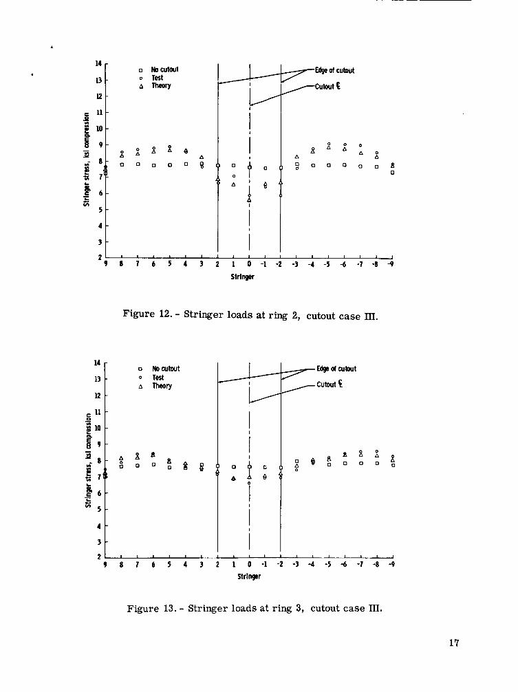
Both the analytical and experimental results of this program for the three cutout sizes are presented in graphical form in figures 5 to 31. Acceptable correlation be- tween analytical and experimental values of stringer loads (or stresses) resulted for all three cutout cases. The maximum e r ro r in stringer load prediction by the analyti- cal method was 6 percent. The analytical values were generally slightly less than the experimentally determined values. Poor correlation between analytical and experi- mental values for panel shears resulted for each of the three cutout cases. The pre- dicted values were lower than the experimental values and were as much as 50 percent lower. The shear was not.constant within a panel; but was at a maximum at station 1, and at a minimum at station 3. Station 1 is the row of rosette strain gages in a partic- ular bay which is closest to the cutout; station 3 is the row farthest from the cutout. The strain-gage stations are shown in figure 4. As the stringers approached the cutout boundary, the stringer load diminished to zero and the panel shear correspondingly in- creased to carry the stringer loads around the cutout.
The experimental values for panel shears being higher than predicted can be explained by the fact that the theory assumes that the skin carr ies only shear and no direct stress. The skin, in reality, does carry direct stress; when a panel is removed by the cutout, i ts direct s t ress load a s well as the stringer load must be carried in shear around the cutout.
5

The load carried as direct stress in the removed skin had less effect on the stringer loads than on the panel shears because part of this skin load was taken out in the bending of the stringers. This was due to the condition in which the middle surface of the skin did not coincide with the centroidal axes of the stringers.
The experimental data showed no panel shear in any of the panels in bay 0 (the bay in which the cutout was made). This was in accordance with the prediction in the theory and resulted because the stringer loads were constant between rings 0 and 1. In other words, the stringer loads a re doubly symmetrical around the cutout center- line.
CONCLUDING REMARKS
The results of this study show the load distribution around a cutout for a com- pressively loaded semimonocoque cylinder. Those skin panels which are subjected to high shear and critical areas of stringer loading may be found through an examination of the data.
The prediction of stringer loads through the stress perturbation technique de- scribed by McComb in his publication "Stress Analysis of Circular Semimonocoque Cylinders with Cutouts, " NACA Report 1251, was sufficiently accurate to justify its use as a method of determining location and the amount of stringer reinforcement which would be required around cutouts in structures of this type.
The difference between the measured and calculated panel shear s t resses is at- tributed to the contribution of the direct s t ress load introduced by the removal of panels in making the cutout. include such stresses in the skin because only cases for the direct loading of the stringers are considered. When direct load is introduced illto the skin, as in the tests of the cylinder reported herein, and when cutouts are introduced, such loading, as well as that in any removed stringers, must be transferred into adjacent panels. For the cylinder reported, the skin carried 41 percent of the total applied load as direct compressive stress ; therefore, good agreement between calculated and experimental shear stresses around the cutouts was not expected. If the stringer loads are known, conservative values for panel shears can be obtained by equating the product of shear flow and bay length to the difference in stringer load in that bay.
The theory presented by McComb makes no attempt to
Manned Spacecraft Center National Aeronautics and Space Administration
Houston, Texas, November 14, 1966 101-08-01-02-72
6

APPENDIX
METHOD OF ANALYSIS
Procedure
The analytical procedure involved the use of the perturbation load technique as presented in reference 1. The assumptions of this theory are:
(1) The cylinder is long, relative to the length of the cutout.
(2) The stringers are uniform and equally spaced around the shell, and the sheet is of constant thickness.
(3) The stringers carry only direct stress, and the sheet takes only shear stress which is constant within each shear panel; thus, stringer stresses vary linearly between adjacent rings.
(4) The rings are uniform and have a finite bending stiffness in their planes; but they do not restrain longitudinal displacements of the stringers. The bending of the rings is inextensional.
(5) The difference between the radius to the middle surface of the sheet and the radius to the neutral axis of a ring is negligible.
(6) The structure is elastic and no buckling occurs.
This technique consists of applying perturbation loads to the cylinder without a cutout. The stresses resulting from these perturbation loads are superimposed on the stresses in the cylinder without a cutout to give the stress distribution for the cylinder with a cutout. A concentrated perturbation load is applied at each point where a stringer is to be interrupted, and a shear perturbation load is applied about the boundary of the removed panel. Simultaneous algebraic equations of equilibrium follow in this section. These equations satisfy the following conditions:
(1) The resultant stringer load must equal zero at the point where the stringer is interrupted. The resultant stringer load would be equal to the sum of the basic stringer load and contributions of all perturbation loads.
(2) The shear perturbation load applied to a given shear panel must equal the basic shear flow of the panel plus the shear-flow contribution of all perturbation loads.
7

The mathematical expressions, as presented in reference 1, for conditions (1) and (2) are, respectively :
The unknowns P and Q are the magnitudes of the concentrated perturbation load
on stringer 7 at ring 5 , and the shear perturbation load about shear panel (5, q), respectively. The values of the coefficients p.. (t,~), (5, q), c.. (5, q) , and qij ( 5 , ~ ) are tabulated in reference 1 for a range of the structural parameters B and C.
477 577
u 3 1.l
, found from equations (1) 577 and Q577 The values of the perturbation loads P
b and (2) are applied to the cylinder and the resultant stresses superimposed on the stresses in the cylinder without a cutout, giving the stress distribution in the cylinder with a cutout.
Sample Calculation
The following sample calculation illustrates the analysis procedure for case III in figure 3 in which four skin panels are removed and three stringers are interrupted by the cutout. The cylinder was designed with the following properties:
m = 36 R = 15 in. L = 12.5 in. a = 0.121 sq in. t = 0.040 in.
2l-l b = Rs = 2.62 in. 6 E = 10.6 X 10 psi
G = 4 X 10 psi I = 0.243 in.
6
4
In Lonformance with the method of reference 1, wherein a prescribed amount of skin plus the stringer combines to form the effective cross-sectional area of the
8

stringer, the effective stringer area is considered to be composed of the actual stringer area plus the skin cross-sectional area for a single panel, o r
A = 0.121 + 2.62 X 0.040
A = 0.226 sq in.
Using these design properties, the structural parameters B and C are
10.6 X lo6 X 0.226(15)2
4 x lo6 x 2.62 x 0.040(12.5)2 = 8.23 B =
C = 0.226(15)6 = 2070 0.243 x 2.62(12.5)3
(3)
(4)
(5)
Concentrated perturbation loads were applied as shown in the sketch below. The concentrated perturbation loads are doubly symmetric about the cutout, and since there is no panel shear for the compressive loading case, no shear perturbation loads were used.
Positive sense of panel shear
-1 0 1 2
Ring
Perturbation loads
9
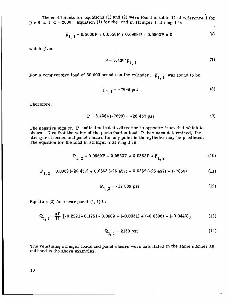
The coefficients for equations (1) and (2) were found in table 11 of reference i for B = 8 and C = 2000. Equation (1) fo r the load in stringer 1 at ring 1 is
(6 1 - - 0.5000P + 0.0558P + 0.0969P + 0.0563P = 0 p1, 1
which gives
1, 1 P = 3.4364p
For a compressive load of 60 000 pounds on the cylinder, - was found to be P1,l
- pl, = -7699 psi
The ref ore,
P = 3.4364 (-7699) = -26 457 psi
The negative sign on P indicates that its direction is opposite from that which is shown. Now that the value of the perturbation load P has been determined, the stringer stresses and panel shears for any point in the cylinder may be predicted.
(9)
The equation for the load in stringer 2 at ring
P = 0.0969P + 0.0563P 192
P1, = 0.0969 (-26 457) + 0.0563 (-26 457)
1 is
1, 2 + 0.0352P +
+ 0.0352(-26 457) + (-7855)
P = -12 839 psi 1,2
Equation (2) for shear panel (1, 1) is
Q1, = [-0.2221- 0.1251 - 0.0689 + (-0.0031) + (-0.0396) + (-0.0443)] (13)
Q1, = 2130 psi
The remaining stringer loads and panel shears were calculated in the same manner as outlined in the above examples.
10

REFERENCES
1. McComb, Harvey G. , Jr. : Stress Analysis of Circular Semimonocoque Cylinders with Cutouts. NACA Report 1251, 1955.
2. Schlechte, Floyd R. ; and Rosecrans, Richard: Experimental Stress Analysis of Stiffened Cylinders with Cutouts - Shear Load. NACA TN 3192, 1954.
3. Schlechte, Floyd R. ; and Rosecrans, Richard: Experimental Stress Analysis of Stiffened Cylinders with Cutouts - Pure Torsion. NACA TN 3039, 1953.
4. Schlechte, Floyd R. ; and Rosecrans, Richard: Experimental Stress Analysis of Stiffened Cylinders with Cutouts - Pure Bending. NACA TN 3073, 1954.
5. McComb, Harvey G., Jr. ; and Low, Emmet F., Jr. : Comparison Between Theo- retical and Experimental Stress in Circular Semimonocoque Cylinders with Rectangular Cutouts. NACA TN 3544, 1955.
11

Ring 3/4 X 2 X 1/16 equal-legged Z - sec tion
36 stringers, 1 x 1 x 1/16 angles
(All dimensions are in inches) r I I I I I I I I 1
I I I I I I I 1 1 c i I 1 I I ! I I
t I I 1 I I I 1 .I 113.9
Figure 1. - Test specimen.
Figure 2. - Test setup.
Case I, two bay cutout
Bay -2 -1 0 1 2
cn - 2 - 1 0 1 2 3 Ring
Case II, three bay cutout
- 2 - 1 0 1 2 3 Ring Case III, four bay cutout
Bay -2 -1 0 1 2
1 I I I I 1-1-4 5 i-2-- 3 0 TI
- 2 - 1 0 1 2 3 cn Ring
Figure 3. - Test specimen cutout cases.
12
. . A,, Rossette gage at station n I-- 2.6" 4
14
u 12
Figure 4. - Typical strain gage installation.
e a s 0
0 A
0
s 0
Figure 5. - Stringer loads at ring 1, cutout case I.
13

14 - 13 -
l2-
E 1 1 - 0 - f 1 0 -
t 9 -
a - 5 7‘ )
- :: m m l
6 - - L
5i 5 -
4 -
3 -
0 No cutout o Test AThWry
B B
2- 9 1 1 7 6 5 4 3 2
i- i i !I i i i
d,
I 0 -
Stringer
7 Of cutout /cutout c.
4
Figure 6. - Stringer loads at ring 2, cutout case I.
6
A
14
E 1 1 -
=: 1 0 - 0 - e
9 -
! 8 - -
8 % m m
5 7 ( t
6 -
5 -
4 -
3 -
-
c i i i i i i
TEdge Of
/cutout Q
Figure 7. - Stringer loads at ring 3, cutout case I.
14

. . 14
l3-
12
11 c 0
5 10 L g 9 - - 2 - 8 - II) II)
71t L Q - P 6 -
5 -
4 -
3 -
2
L -
B Nocutout Edge of cutout 0 Test
-
cutout (i A Theow -
0 1I r l
0 0
0 A .
0 A
-
- A
8 8
' O " " d d 8 * i j
i
I A A
8 s o o o o [ ,
i o
I 1 I I I 1 1 I I 1 I 1 I I I
14
13
8 0
0 0
A
d 0
No cutout Test Theory
cutout
%
0
A
0
0
A 0
B 0
a O
4
3
2 9 8 7 6 5 4 3 2 1 0 - 1 - 2 - 3 - 4 - 5 - 6 - 7 - 8 - 9
Stringer
Figure 9. - Stringer loads at ring 2, cutout case II.
15

Fofcubut utwt Q
14 0 Nowtwt o TIst A ThWly
4 t
I
I
B 8 a s, B B
3 - 2 , , , I ,
9 8 7 6 5 4 3 2 1 0 -1 -2 -3 -4 -5 -6 -1 - 8 - 9 Stringer
Figure 10. - Stringer loads at ring 3, cutout case II.
Cutout Q 0 Nocutwt o Test A Theow
I I i
I
9 a 7 6 5 4 3 2 1 0 - 1 - 2 - 3 - 4 - 5 - 6 - 7 - 8 - 9 Strlnger
.
Figure 11. - Stringer loads at ring 1, cutout case 111.
16
0 Nocutout 0 Test A Theory
B 0 a
0
Figure 12. - Stringer loads at ring 2, cutout case III.
14
13
12
0 Nocutout Edge of cubut 0 Test A Theory
Figure 13. - Stringer loads at ring 3, cutout case 111.
17

cutout usd I
Figure 14. - Panel shear stress T bay 1 and station 1. XY'
4 - - lest --- Theory
3 - Cutout case I
2 - - 3
e* l -
t L o--- , a e 5 5 -1 s n
la m
I ---- _____-_--_- -__ - --- - -
I
i i
-2 -
-3 -
-4 J
9 8 7 6 5 4 3 2 1 0 -1 -2 -3 -4 -5 -6 -7 -8 -9 Stringer
Figure 15. - Panel shear stress T bay 1 and station 2. XY'
18

4
3
2
B l 3
5 5 -1
c t o Y)
- e B
-2
-3
-4
cutout ow I
Stringer
Figure 16. - Panel shear stress T bay 1 and station 3. XY’
4 [ - T a t --- Theory 3
I i I i Cutout Qsb I
-3
-2 1 9 0 1 6 5 4 3 2 1 0 -1 -2 -3 -4 -5 -6 -1 -8 -b
Stringer
Figure 17. - Panel shear stress T bay 2 and station 1. Xy’
19

Cutout case I
4
3
2
22 L l
VX
e - 0
-
v) v)
-c
L m a S v)
5 -1 5 p.
-2
-3
-4
Stringer
Figure 18. - Panel shear stress T bay 2 and station 2. Xy’
20
Cutout case I
8 7 6 5 4 3 2 1 0 -1 -2 -3 -4 -5 -6 -7 -8 -9 Stringer
Figure 19. - Panel shear stress T bay 2 and station 3. XY’

.
-3
-2 I 1
i i i
Edge of cutout
Cutout $
-4 1 I I I 1 I 1 I I I 1 1 I 1 I I I I
9 8 7 6 5 4 3 2 1 0 -1 -2 -3 -4 -5 -6 -7 -8 -9 Stringer
Figure 20. - Panel shear stress T bay 1 and station 1. Xy' II 3
- Test --- Theory
-3 -* i
--I i i i
cutout case II
Figure 21. - Panel shear stress T bay 1 and station 2. Xy'
21

4
3
2 - 3
3 ? 1
e = o
5 = -1 6
I- m U
i c
-2
-3
4
- Test --- Theory
I I
rF 1
r E d g e of cutout 4 u t o u t E
cutout case II
9 8 7 6 5 4 3 2 1 0 -1 -2 -3 -4 -5 -6 -7 -8 -9 Stringer
Figure 22. - Panel shear stress T bay 1 and station 3. Xy’
Cutout u s e l l
4 -
- . ------- - _ _ _ _ _ _ _
- Test --- Theory 3 -
2 -
3 I- PI-
5i
m U e
5 = -1
0
- I
c 6 I
i i
-2 -
-3 -
-4 I
9 8 7 6 5 4 3 2 1 0 -1 -2 -3 -4 -5 -6 -7 -8 -9 Strlnger
Figure 23. - Panel shear stress T bay 2 and station 1. Xy’
22

. 4
3
I 2
-2
-3
- Test --- meow
Edp of cutwt P-k- -cutout c Cutout case TI
9 8 7 6 5 4 3 2 1 0 ,-1 -2 -3 -4 -5 -6 -1 -8 -9 Stringer
Figure 24. - Panel shear stress 7 bay 2 and station 2. Xy’
-2
-3
- Test --- Theory
Cutout case II
I !
Figure 25. - Panel shear stress 7 bay 2 and station 3. XY’
23

- Test --- Theory
Cutout case m
-6 1 I I 1 1 I I I 1 I I I 1 1 1 I 1
9 8 7 6 5 4 3 2 1 0 -1 -2 -3 -4 -5 -6 -7 -8 -9 Stringer
Figure 26. - Panel shear stress T bay 1 and station 1. Xy’
,
Cutout case m
Figure 27. - Panel shear stress T bay 1 and station 2. Xy’
24

.
5
fi -2
f -1 - .)
-3
-4
-5
Figure 28. - Panel shear stress 7 bay 1 and station 3. Xy'
- Test --- Theoly :I 4
3 1 2 c
I I ~ E d g e d c u t a r t
I I
f -1
5 -2 -
- - 0
n
-3 - - 4 -
- 5 -
I -
Figure 29. - Panel shear stress 7 bay 2 and station 1. Xy'
25

. ,
Cutout case III
9 a 7 6 5 4 3 2 1 o -1 -2 -3 -4 -5 -6 -7 -a -9 Stringer
Figure 30. - Panel shear stress T bay 2 and station 2. Xy’
Cutout case
Figure 31. - Panel shear stress T bay 2 and station 3. Xy’
26 NASA-Langley, 1961 S-98


![Super Lift Coefficient of Co-Flow Jet Circular Cylinder · 1960s, Lockwood [12] from NASA Langley conducted experiment of a circular cylinder using tangential blowing and achieved](https://static.fdocuments.us/doc/165x107/5e81b73b95b2315bdc71bc63/super-lift-coefficient-of-co-flow-jet-circular-cylinder-1960s-lockwood-12-from.jpg)


![Control of flow around a circular cylinder using a ... · the circular cylinder [1, 2]. Figure 1: Drag coefficient of rough and smooth circular cylinders. It is also known that the](https://static.fdocuments.us/doc/165x107/5e9700258a215e1f8f73e60f/control-of-flow-around-a-circular-cylinder-using-a-the-circular-cylinder-1.jpg)