
stress, stability and vibration of complex, branched shells of revolution
41
Computers A Structures. Vol. 4, pp. 399-435. Pergamon Pruss 1974. Printed In Great Britain STRESS, STABILITY AND VIBRATION OF COMPLEX, BRANCHED SHELLS OF REVOLUTION DAVID BUSHNELL Lockheed Palo Alto Research Laboratory, Palo Alto, California, U.S.A. Abstract-A comprehensive computer program, designated BOSOR4, for analysis of the stress, stability and vibration of segmented, ring-stiffened, branched shells of revolution and prismatic shels and panels is described. The program performs largedeflection axisymmetric stress analysis, small-deflecton nonsyn- metric stress analysis, modal vibration analysis with aisymmetric nonlinear prestress included, and buckling analysis with axisymmetric or nonsymmetric prestress. One of the main advantages of the code is the provision for realistic engeering details such as eccentric load paths, internal supports, arbitrary branching conditions, and a library' of wall constructions. The program is based on thefiniteffe-renoenetrmethod which is very rapidly convergent with increasing numbers of mesh points. The organization of the program is briefly described with flow of calculations charted for each of the types of analysis. Overlay charts and core storage requirements are given for the CDC 6600, EBM 3701165, and UNIVAC 1108 versions of BOSOR4. A largenumber ofcass isinchded to demonstrate thescopeand practicalityoftheprogramperiod. INTRODUMI¶ON THE PURPosE of this paper is to describe a computerized method of analysis for composite, branched shells of revolution. The main advantage of the analysis method and computer program is its direct and efficient applicability to practical engineering design problems involving very complex shells of revolution or prismatic shell structures such as corrugated panels or noncircular cylinders. Emphasis is placed on analytical results for a variety of 'real-world' engineering problems. Details of the analysis method are reported in Ref. [1]. Extensive literature exists on analysis and computer programs for shells and solids of revolution. Figure 1 contains the names of many computer programs and names of originators of other computer programs that cover this field. The names are given in a 'coordinate system' arranged such that increasingly 'general purpose' computer codes lie increasing distances from both axes. Other codes, existingjust outside ofthe region depicted, apply to structures that are 'almost' shells of revolution, such as shells with cutouts, shells with material properties that vary around the circumference, or panels of shells of revolution. The region shown in Fig. 1 is divided by a heavy line into two fields: Programs lying within the heavy line are based on numerical methods that are essentially one-dimensional, that is, the dependent variables are separable and only one spatial variable need be dis- cretized; programs lying outside the heavy line are based on numerical methods in which two spatial variables are discretized. It is generally true that analysis methods and programs lying outside the heavy line require perhaps an order of magnitude more computer time for a given case with given nodal point density than do those lying inside the line. This distinction arises because the bandwidths and ranks of equation systems in two-dimensional numerical analyses are greater than those in one-dimensional numerical analyses. Certain of the areas in Fig. I are blank. Those near the origin correspond in general to cases for 399
Transcript of stress, stability and vibration of complex, branched shells of revolution
Computers A Structures. Vol. 4, pp. 399-435. Pergamon Pruss 1974. Printed In Great Britain
STRESS, STABILITY AND VIBRATION OF COMPLEX,BRANCHED SHELLS OF REVOLUTION
DAVID BUSHNELL
Lockheed Palo Alto Research Laboratory, Palo Alto, California, U.S.A.
Abstract-A comprehensive computer program, designated BOSOR4, for analysis of the stress, stabilityand vibration of segmented, ring-stiffened, branched shells of revolution and prismatic shels and panelsis described. The program performs largedeflection axisymmetric stress analysis, small-deflecton nonsyn-metric stress analysis, modal vibration analysis with aisymmetric nonlinear prestress included, and bucklinganalysis with axisymmetric or nonsymmetric prestress. One of the main advantages of the code is theprovision for realistic engeering details such as eccentric load paths, internal supports, arbitrary branchingconditions, and a library' of wall constructions. The program is based on thefiniteffe-renoenetrmethodwhich is very rapidly convergent with increasing numbers of mesh points. The organization of the programis briefly described with flow of calculations charted for each of the types of analysis. Overlay charts andcore storage requirements are given for the CDC 6600, EBM 3701165, and UNIVAC 1108 versions ofBOSOR4. A largenumber ofcass isinchded to demonstrate thescopeand practicalityoftheprogramperiod.
INTRODUMI¶ON
THE PURPosE of this paper is to describe a computerized method of analysis for composite,branched shells of revolution. The main advantage of the analysis method and computerprogram is its direct and efficient applicability to practical engineering design problemsinvolving very complex shells of revolution or prismatic shell structures such as corrugatedpanels or noncircular cylinders. Emphasis is placed on analytical results for a variety of'real-world' engineering problems. Details of the analysis method are reported in Ref. [1].
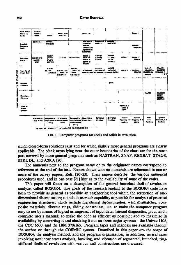
Extensive literature exists on analysis and computer programs for shells and solids ofrevolution. Figure 1 contains the names of many computer programs and names oforiginators of other computer programs that cover this field. The names are given in a'coordinate system' arranged such that increasingly 'general purpose' computer codes lieincreasing distances from both axes. Other codes, existingjust outside ofthe region depicted,apply to structures that are 'almost' shells of revolution, such as shells with cutouts, shellswith material properties that vary around the circumference, or panels of shells of revolution.
The region shown in Fig. 1 is divided by a heavy line into two fields: Programs lyingwithin the heavy line are based on numerical methods that are essentially one-dimensional,that is, the dependent variables are separable and only one spatial variable need be dis-cretized; programs lying outside the heavy line are based on numerical methods in whichtwo spatial variables are discretized. It is generally true that analysis methods and programslying outside the heavy line require perhaps an order of magnitude more computer timefor a given case with given nodal point density than do those lying inside the line. Thisdistinction arises because the bandwidths and ranks of equation systems in two-dimensionalnumerical analyses are greater than those in one-dimensional numerical analyses. Certainof the areas in Fig. I are blank. Those near the origin correspond in general to cases for
399
400 DAVID BUSHNELL
1 - - -V P r- [ - - ,- {F-TRAR.Wel~l MARCALSeldl - W N RAAS- (4) FAISS (I) 014555(31Rslid. WASP ('IC() rpmCS
moesasc4i) BD555(l) I 085544) mRR04(I =20411lgft10d15am1i) I ftm)) 03014311) R (Z
o1l. CIMRLLI(S) 11ASTICI- LASTII!( if) I
,!AD IIOII
SOSORS ROSOR 3 8R5511S 3050558.5.-A SADISTIC I! SMACS SAKAOS lADER(IS) KALNIRS X&.511 (AUIUINI SAOAW SABORS-IR-I UNNDI I SA~On3 !ACR VLR IALRDAWASP DrAM!!1 STARS IC STA a
SALORS
l 090OII MAUCL 11090P.1 Boom 111.7) UU wt(7
Tba-W.llrd IILSOri- eO tJ#DAYT(E1; LAt ICI SCHAxEFE ADLWHI(1t 11CAIII(III) ,OWNLS it SAIXHi - U OW " o
S HAmRF( Is) YAUA (1021 MARTIN oo
Swkw SCAR
WIACI - . CRE
R (10LSUrR iI;R
A -W,- , AW-* fb-.1*4 -- "W . e- i" - -10-- --
SI- Ti LARN
Stw S~te'141 1041,
INCREASING GENERALITY OF ANALYSIS OR PHEN4OMENON
Flo. 1. Computer programs for shells and solids in revolution.
which closed-form solutions exist and for which slightly more general programs are clearlyapplicable. The blank areas lying near the outer boundaries of the chart are for the mostpart covered by more general programs such as NASTRAN, SNAP, REXBAT, STAGS,STRUDL, and ASKA [20].
The numerals next to the program name or to the originator names correspond toreferences at the end of the text. Names shown with no numerals are referenced in one ormore of the survey papers, Refs. [20-23]. These papers describe the various numericalprocedures used, and in one case (21] hint as to the availability of some of the codes.
This paper will focus on a description of the general branched shell-of-revolutionanalyzer called BOSOR4. The goals of the research leading to the BOSOR4 code havebeen to provide as general as possible an engineering tool within the restriction of one-dimensional discretization; to include as much capability as possible for analysis of practicalengineering structures, which include meridional discontinuities, weld mismatches, com-posite materials, discrete rings, sliding constraints, etc. to make the computer programeasy to use by means of logical arrangement of input data, internal diagnostics, plots, and acomplete user's manual; to make the code as efficient as possible; and to maximize itsavailability by converting it and checking it out on three major systems-the Univac 1108,the CDC 6600, and the IBM 370/165. Program tapes and manuals are available throughthe author or through the COSMIC system. Described in this paper are the scope ofBOSOR4, the analysis method, and the program organization; in addition, several casesinvolving nonlinear stress analysis, buckling, and vibration of segmented, branched, ring-stiffened shells of revolution with various wall constructions are discussed.

Stress, Stability and Vibration of Coiflex, Branched Shells of Revolution
SCOPE OF THE BOSOR4 COMPUTER PROGRAM
The BOSOR4 code performs stress, stability, and vibration analyses of segmented,branched, ring-stiffened, elastic shells of revolution with various wall constructions.Figure 2 shows some examples of branched structures which can be handled by BOSOR4.Figure 2a represents part of a multiple-stage rocket treated as a shell of seven segments;Fig. 2b represents part of a ring-stiffened cylinder in which the ring is treated as two shellsegments branching from the cylinder; Fig. 2c shows the same ring-stiffened cylinder, butwith the ring treated as 'discrete', that is the ring cross section can rotate and translate butnot deform, as it can in the model shown in Fig. 2b. Figures 2d-f represent branchedprismatic shell structures, which can be treated as shells of revolution with very large meancircumferential radii of curvature, as described in Ref. [25] and later in this paper.
r n
Numbers W (d)
77
(C)
Cf)
FIG. 2. Examples of branched structures which can be analyzed with BOSOR4.
The program is very general with respect to geometry of meridian, shell-wall design,edge conditions, and loading. It has been thoroughly checked out by comparisons withother known solutions and tests. The BOSOR4 capability is summarized in Table 1. Thecode represents three distinct analyses:
(1) A nonlinear stress analysis for axisymmetric behavior of axisymmetric shellsystems (large deflections, elastic)
(2) A linear stress analysis for axisymmetric and nonsymmetric behavior of axi-symmetric shell systems submitted to axisymmetric and nonsymmetric loads
(3) An eigenvalue analysis in which the eigenvalues represent buckling loads orvibration frequencies of axisymmetric shell systems submitted to axisymmetricloads. (Eigenvectors may correspond to axisymmetric or nonsymmetric modes.)
401
DAVID BUSHNELL
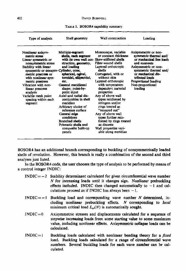
TABLE 1. BOSOR4 capability summary
Type of analysis Shell geometry Wall construction Loading
Nonlinear axisym- Multiple-segment Monocoque, variable Axisymmetric or non-metric stress shells, each segment or constant thickness symmetric thermal and/
Linear symmetric or with its own wall con- Skew-stiffened shells or mechanical line loadsnonsymmetric stress struction, geometry, Fiber-wound shells and moments
Stability with linear and loading Layered orthotropic Axisymmetric or non-symmetric or nonsym- Cylinder, cone, shells symmetric thermal and/metric prestress or spherical ogival, Corrugated, with or or mechanical dis-with nonlinear sym- toroidal, ellipsoidal, without skin tributed loadsmetric prestress etc. Layered orthotropic Proportional loading
Vibration with non- General meridional with temperature- Non-proportionallinear prestress shape; point-by- dependent material loadinganalysis point input properties
Variable mesh point Axial and radial dis- Any of above wallspacing within each continuities in shell types reinforced bysegment meridian stringers and/or
Arbitrary choice of rings treated asreference surface "smeared out"
General edge Any of above wallconditions types further rein-
Branched shells forced by rings treatedPrismatic shells and as discrete
composite built-up Wall properties vari-panels able along meridian
BOSOR4 has an additional branch corresponding to buckling of nonsymmetrically loadedshells of revolution. However, this branch is really a combination of the second and thirdanalyses just listed.
In the BOSOR4 code, the user chooses the type of analysis to be performed by means ofa control integer INDIC:
INDIC=-2
INDIC=-I
Stability determinant calculated for given circumferential wave numberN for increasing loads until it changes sign. Nonlinear prebucklingeffects included. INDIC then changed automatically to -I and cal-culations proceed as if INDIC has always been - 1.
Buckling load and corresponding wave number N determined, in-cluding nonlinear prebuckling effects. M corresponding to localminimum critical load Lc,(N) is automatically sought.
INDIC=O Axisymmetric stresses and displacements calculated for a sequence ofstepwise increasing loads from some starting value to some maximumvalue, including nonlinear effects. Axisymmetric collapse loads can becalculated.
INDIC= I Buckling loads calculated with nonlinear bending theory for a fixedload. Buckling loads calculated for a range of circumferential wavenumbers. Several buckling loads for each wave number can be cal-culated.
402
Stress, Stability and Vibration of Cft~ileic, Branched Shells of Revolution
INDIC=2 Vibration frequencies and mode shapes calculated, including the effectsof prestress obtained from axisymmetric nonlinear analysis. Severalfrequencies and modes can be calculated for each circumferential wavenumber.
INDIC=3 Nonsymmetric or symmetric stresses and displacements calculated fora range of circumferential wave numbers. Linear theory used. Resultsfor each harmonic are automatically superposed. Fourier series fornonsymmetric loads are automatically computed or may be providedby user.
INDIC=4 Buckling loads calculated for nonsymmetrically loaded shells. Pre-buckled state obtained from linear theory (INDIC=3) or read in fromcards. 'Worst' meridional prestress distribution (such as distributioninvolving maximum negative meridional or hoop prestress resultant)chosen by user, and this particular distribution is assumed to be axi-symmetric in the stability analysis, which is the same as that for thebranch INDIC= 1.
The variety of buckling analyses (INDIC= -2, -1, 1, and 4) is provided to permit theuser to approach a given problem in a number of different ways. There are cases for whichan INDIC= -I analysis, for example, will not work. The user can then resort to anINDIC= -2 analysis, which requires more computer time, but which is generally morereliable. Buckling of a shallow spherical cap under external pressure is an example. In anINDIC= -I analysis of the cap, the program generates a sequence of loads that ordinarilyshould converge to the lowest buckling load, with nonlinear prebuckling effects included.Depending on the cap geometry and the user-provided initial pressure, however, one ofthe loads in the sequence may exceed the axisymmetric collapse pressure of the cap. Thisphenomenon can occur if the bifurcation buckling loads are just slightly smaller than theaxisymmetric collapse loads. The user can obtain a solution with use of INDIC= - 2, inwhich the bifurcation load is approached from below in a 'gradual' manner. The BOSOR4manual [1] contains an example of this case. A somewhat different illustration is providedin the section on analytical results.
The branch INDIC= I is provided because it is sometimes desirable to know severalbuckling eigenvalues for each circumferential wave number, N, and because there may existmore than one minimum in the critical load vs N-space. This is especially true for compositeshell structures with many segments and load types. Such a structure can buckle in manydifferent ways. The designer may have to eliminate several possible failure modes, not justthe one corresponding to the lowest pressure, for example. The INDIC=4 branch isprovided for two reasons: The user can calculate buckling under nonsymmetric loads with-out having to make two separate runs, an INDIC=3 run and an INDIC= 1 run. Inaddition, this branch permits the user to bypass the prebuckling analysis and read pre-buckling stress distributions and rotations directly from cards. This second feature is veryuseful for the treatment of composite branched panels under uniaxial or biaxial compression.
The BOSOR4 program, although applicable to shells of revolution, can be used forthe buckling analysis of composite, branched panels by means of a 'trick' described indetail in Ref. [25]. This 'trick' permits the analysis of any prismatic shell structure that issimply-supported at particular stations along the length. Any boundary conditions can be
403

DAVID BUSHNELL
used along generators. In Ref. [25] many examples are given, including nonuniformlyloaded cylinders,. noncircular cylinders, corrugated panels, and cylinders with stringerstreated as discrete. This paper gives other examples.
ANALYSIS METHOD
The assumptions upon which the BOSOR4 code is based are:
(I) The wall material is elastic.(2) Thin-shell theory holds; i.e. normals to the undeformed surface remain normal
and undeformed.(3) The structure is axisymmetric, and in vibration analysis and nonlinear stress
analysis the loads and prebuckling or prestress deformations are axisymmetric.(4) The axisymmetric prebuckling deflections in the nonlinear theory (INDIC=O,
-1, 2), while considered finite, are moderate; i.e. the square of the meridionalrotation can be neglected compared with unity.
(5) In the calculation of displacement and stresses in nonsymmetrically loaded shells(INDIC-3), linear theory is used. This branch of the program is based onstandard small-deflection analysis.
(6) A typical cross-section dimension of a discrete ring stiffener is small compared withthe radius of the ring.
(7) The cross-sections of the discrete rings remain undeformed as the structure deforms,and the rotation about the ring centroid is equal to the rotation of the shellmeridian at the attachment point of the ring (except, of course, if the ring istreated as a flexible shell branch).
(8) The discrete ring centroids coincide with their shear centers.(9) If meridional stiffeners are present, they are numerous enough to include in the
analysis by an averaging or 'smearing' of their properties over any parallel circleof the shell structure, meridional stiffeners can be treated as discrete though the'trick' described in Ref. [25].
The analysis is based on energy minimization with constraint conditions. The totalenergy of the system includes strain energy of the shell segments and discrete rings, potentialenergy of the applied line loads and pressures, and kinetic energy of the shell segments anddiscrete rings. The constraint conditions arise from displacement conditions at theboundaries of the structure, displacement conditions that may be prescribed anywherewithin the structure, and at junctures between segments. The constraint conditions areintroduced into the energy functional by means of Lagrange multipliers.
These components of energy and constraint conditions are initially integro--differentialforms. The circumferential dependence is eliminated by separation of variables. Dis-placements and meridional derivatives of displacements are then written in terms ofthe shellreference surface displacement components ul, v, and wi at the finite-difference mesh pointsand Lagrange multipliers Al. Integration is performed simply by multiplication of theenergy per unit length of meridian by the length of the 'finite difference element', to bedescribed below.
In the nonlinear axisymmetric stress analysis the energy expression has terms linear,quadratic, cubic, and quartic in the dependent variables ui and wi. The cubic and quartic
404
Stress, Stability and Vibration of Coinjlek, Bminched Shells of Revolution
energy terms arise from the 'rotation-squared' terms that appear in the expression forreference surface meridional strain and in the constraint conditions. Energy minimizationleads to a set of nonlinear algebraic equations that are solved by the Newton-Raphsonmethod. Stress and moment resultants are calculated in a straightforward manner fromthe mesh-point displacement components through the constitutive equations and thekinematic relations.
The results from the nonlinear axisymmetric or linear nonsymmetric stress analysisare used in the eigenvalue analyses for buckling and vibration. The 'prebuckling' or'pre-stress' meridional and circumferential stress resultants N10 and N20 and the meridionalrotation Xo appear as known variable coefficients in the energy expressions that governbuckling and vibration. These expressions are homogeneous quadratic forms. The valuesof a parameter (load or frequency) that render the quadratic forms stationary with respectto infinitesimal variations of the dependent variables represent buckling loads or naturalfrequencies. These eigenvalues are calculated from a set of linear homogeneous equations.More will be written about the bifurcation buckling eigenvalue problems in the followingparagraphs.
Details of the analysis are given in Refs. [1, 26 and 27]. Only three aspects will bedescribed here: the 'finite-difference element', the form of the stability eigenvalue problem,and the effect of branched systems on the configuration of the stiffness matrix.
THE 'FINITE-DIFFERENCE' ELEMENT
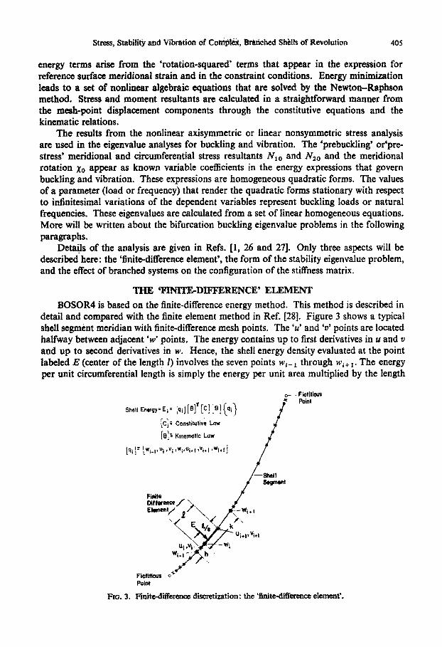
BOSOR4 is based on the finite-difference energy method. This method is described indetail and compared with the finite element method in Ref. [28]. Figure 3 shows a typicalshell segment meridian with finite-difference mesh points. The 'V' and 'v' points are locatedhalfway between adjacent 'w' points. The energy contains up to first derivatives in u and vand up to second derivatives in w. Hence, the shell energy density evaluated at the pointlabeled E (center of the length 1) involves the seven points we- through wi+1. The energyper unit circumferential length is simply the energy per unit area multiplied by the length
-Fictilious
Shell Energy=E 1 i I I
ic! Constitutve Low[By Kinemrtic Law
tq'] [wi l~u;,vi ,wt,ui+ avid ,wi.l j
-Shells egmet
FiniteDifference 7Ehmeny Se x\wi.I.
FictitioasPoint
FIG. 3. Finite-difference discretization: the 'finite-difference element'.
405
4DAVID BUSHNELL
of the finite-difference element I, which is the arc length of the reference surface betweentwo adjacent u or v points. In Ref. [28] it is shown that this formulation yields a (7 x 7)stiffness matrix corresponding to a constant-strain, constant-curvature-change finiteelement that is incompatible in normal displacement and rotation at its boundaries but thatin general gives very rapidly convergent results with increasing density of nodal points.Note that two of the w-points lie outside of the element. If the mesh spacing is constant,the algebraic equations obtained by minimization of the energy with respect to nodaldegrees-of-freedom can be shown to be equivalent to the Euler equations of the variationalproblem in finite form. Further description and proofs are given in Ref. 128].
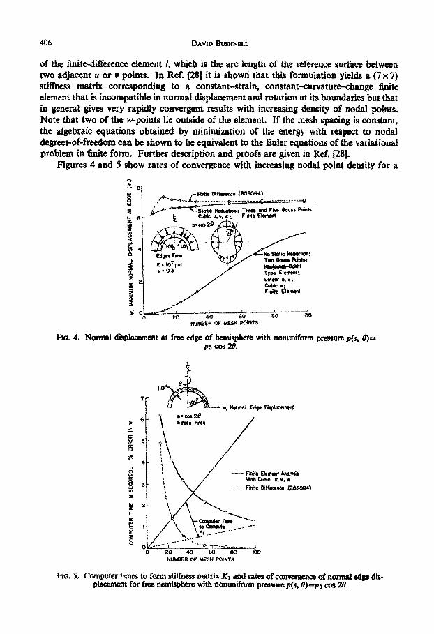
Figures 4 and 5 show rates of convergence with increasing nodal point density for a
Ls Finite Difaiffse (81R4)
stc Rodoni TrW and Five Gouss Points6 - Cub uV.w; Finite Element
e 4
Ede Free , No Stat;R~do-
:s / Finite ittmentnI
0 40 60 eV i 0
NUMBER OF WESN POINTS
Fro. 4. Normal displaaement at free edge of hemisphere with nonuniform pressure p(s, 0)-po cos 28.
.07
P Cw, t 2DEdges Free/
4t [L i / - Firaite £Ett AUIyIIsks 31 > Wdh Cubic u,tw
W 2
NUMBER OF MESH POINTS
xo. S. Computer times to form stiffness matrix K1 and rates of convagence of normal edge dis-placement for free hemisphere with nonuniform pressure p(s, 9)=po cot 20.
406

Stress, Stability and Vibration of Coniple, Branched Shells of Revolution
poorly conditioned problem-a stress analysis of a thin, nonsymmetrically loaded hemi-sphere with a free edge. The finite-element results were obtained by programming variouskinds of finite elements into BOSOR4. The computer time for computation of the stiffnessmatrix K1 is shown in Fig. 5. A much smaller time for computation of the finite-differenceK, is required because there are fewer calculations for each 'Gaussian' integration pointand because there is only one 'Gaussian' point per finite-difference element. Other com-parisons of rate of convergence with the two methods used in BOSOR4 are shown forbuckling and vibration problems in Ref. [281.
FORMULATION OF THE STABILITY PROBLEM
The bifurcation buckling problem represents perhaps the most difficult of the threetypes of analyses performed by BOSOR4. It is practical to consider bifurcation bucklingof complex, ring-stiffened shell structures under various systems of loads, some of whichare considered to be known and constant, or 'fixed' and some of which are considered tobe unknown eigenvalue parameters, or 'variable'.
The notion of 'fixed' and 'variable' systems of loads not only permits the analysis ofstructures submitted to nonproportionally varying loads, but also helps in the formulationof a sequence of simple of 'classical' eigenvalue problems for the solution of problemsgoverned by 'nonclassical' eigenvalue problems. An example is a shallow spherical capunder external pressure. Very shallow caps fail by nonlinear collapse, or snap-throughbuckling, not by bifurcation buckling. Deep spherical caps fail by bifurcation buckling inwhich nonlinearities in prebuckling effects are not particularly important. There is a rangeof cap geometries for which bifurcation buckling is the mode of failure and for which thecritical pressures are very much affected by nonlinearities in prebuckling behavior. Theanalysis of this intermediate class of spherical caps is simplified by the concept of 'fixed' and'variable' pressure
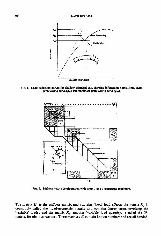
Figure 6 shows the load-deflection curve of a shallow cap in this intermediate range.Nonlinear axisymmetric collapse (p,,l), linear bifurcation (pub), and nonlinear bifurcation(Pub) loads are shown. The purpose of the analysis referred to in this section is to determinethe pressure pnb. It is useful to consider the pressure pn, as composed of two parts
Pnb=P +Po
in which p1 denotes a known or 'fixed' quantity, andp'denotes an undetermined or 'variable'quantity. The fixed portion pr is an initial guess or represents the results of a previousiteration. The variable portion p" is the remainder, which can be determined from areasonably simple eigenvalue problem, as will be described. It is clear from Fig. 7 that ifpa is fairly close to pt the behavior in the range p=pf ip" is reasonably linear. Thus, thecigenvalue pb can be calculated by means of a sequence of eigenvalue problems throughwhich ever and ever smaller values p" are determined and added to the known results p1
from the previous iterations. As the BOSOR4 computer program is written the initial guessp1 need not be close to the solution Pnb-
In the bifurcation stability analysis it is necessary to develop three matrices corres-ponding to the eigenvalue problem
Klx+AK 2 x+A2'K3x=O.
407
(1)
DAVID BUSHNELL
vOLUME DtSPLACED
Fio. 6. Load-deflection curves for shallow spherical cap, showing bifurcation points from linearprebuckling curve (pan) and nonlinear prebuckling curve (P,.6).
(b)
Fio. 7. Stiffness matrix configuration with types I and 3 constraint conditions.
The matrix K1 is the stiffness matrix and contains 'fixed' load effects; the matrix K2 iscommonly called the 'load-geometric' matrix and contains linear terms involving the4variable' loads; and the matrix K3 , another 'variable'-load quantity, is called the A2-matrix, for obvious reasons. These matrices all contain known numbers and are all banded.
408
Stress, Stability and Vibration of Complex, Branched Shells of Revolution
The bifurcation buckling problem is stated mathematically in terms of the secondvariation of the total energy. For a shell the second variation is given by
2+2[ 2 ][C]{60= +2[0 ][C]{62 }+2[NT ]{ 2 }
+[bu, 6v, bw][P] 6v rdOds (2)6w
in which so, El, 62 signify, respectively, strain vectors (containing reference surface strainsand changes in curvature) that are zeroth, first, and second order in the displacementvariations bu, bv, 6w and that contain prebuckling quantities; [C] represents the 6 x 6matrix of stress-resultant-strain coefficients; NT represents thermal effects; [P] represents'pressure-rotation' effects; s and 0 are the meridional and circumferential coordinates,respectively; and r is the local parallel circle radius of the shell of revolution.
The linear Iat of the 'strain. incremntduring buckling', s', contains .the prebucklingmeridional rotation Xo. The prebuckling strain vector so contains terms both linear andquadratic in prebuckling rotations. If, in a reasonably small neighborhood ( )" of aknown prebuckling state ( )f, the behavior of the shel can be considered linear withrespect to load, then in this neighborhood the second variation of the shell strain energycan be written he -form
62Uf= | | (AI +AA2 +)2A3)rdsd0. (3)
Formulas for A,, A2 and A3 are given in Ref. [1]. The development is expanded in Ref. 11]to include discrete ring strain energy and constraint conditions. If the integration is per-formed and the gecond variation is 'minimized' with repect to the deendent wariables6u1, buv, bw1, and the Lagrange multipliers, the eigenvalue problem of equation (1) results.The method of solution of this problem is described in Ref. [1]. An eigenvalue problem ofthe same form was derived and solved by Anderson et al. [29]. Eigenvalues are extractedby means of the method of inverse power iterations with spectral shifts.
STIFFNESS MATRICES FOR BRANCHED SYSTEMS
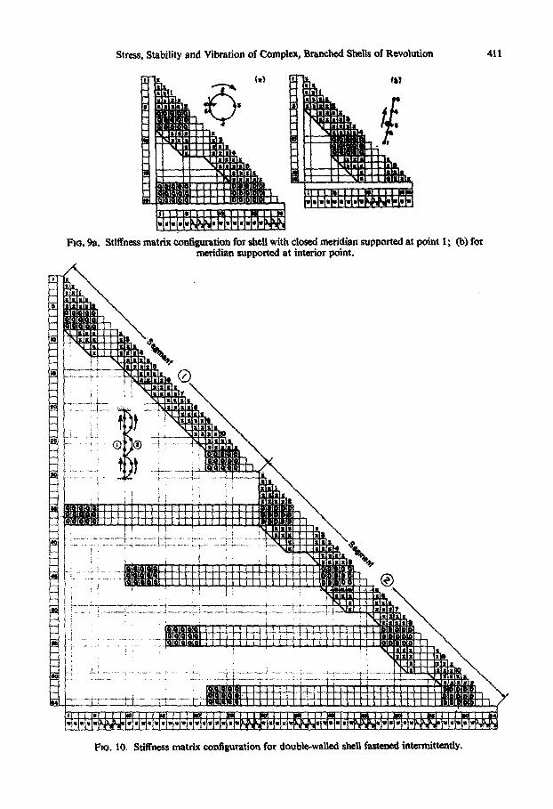
Figures 7-10 show the configurations of stiffness matrices for various types of branchingconditions. These matrices are specifically for prebuckling axisymmetric problems in whichonly u and w displacement components exist, and for which there are only three equationsfor each constraint point (u, w, and rotation compatibility). However, the forms of stabilityor-vibration or nonsymmetric stress stiffness matrices are similar, the only differences beingthat the 'point' stiffness matrices are 7 x 7 rather than 5 x 5, and there are four lambda'sfor each boundary or juncture condition rather than three. In Figs. 7 and 8 the 5 x 5element squares 'BCB' represent 'local' stiffness matrices contributed by each finite-difference element (see Fig. 3). The rectangular 3 x 5 and 5 x 3 matrices 'QD' and 'D'represent the constraint conditions obtained by minimization of the energy with respect tothe Lagrange multipliers. The shaded blocks receive contributions from the constraintconditions. Reference [1] shows what the various contributions are.
409

DAVID BUSHNELL
Fio. 8. Stiffness matrix configuration with type 4 and 5 constraint conditions.
There are five types of constraint conditions recognized by BOSOR4: Type 1 is asimple 'one-sided' constraint condition (e.g., boundary condition) not at the termination ofa segment (it can be at the beginning as"in Fig. 7); Type 2 is a simple 'one-sided' constraintcondition (boundary condition) at the termination of a segment (shown in Fig. 10, Seg. 1);Type 3 is a juncture condition in which the termination of a segment is connected in someway to a nonadjacent previous point (Fig. 7); Type 4 is a juncture condition in which apoint embedded within a segment is connected to a nonadjacent previous point (Fig. 8);and Type 5 is a juncture condition in which the termination of Segment (i) is connected tothe beginning of Segment (i+1). Figure 9a shows a stiffness matrix configuration "twould result for a complete toroidal shell held at one point; 9b gives an example of ameridian free at the boundaries and constrained at an interior point. Figure 10 shows astiffness matrix configuration corresponding, for example, to a corrugated semisandwichpanel in which the corrugations are rivefed to the flat sheet at intervals along the surface.Other examples are given in Ref. [1].
BOSOR4 PROGRAM ORCMUZATION
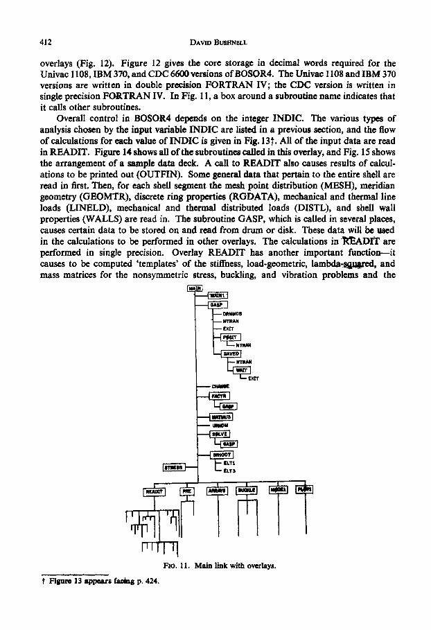
The BQSOR4 program consists of a main program MAIN and six overlays calledREADIT, PRE, ARRAYS, BUCKLE, MODEl, AND PLOTL. Figure 11 shows theUnivac I 108XEC8 and IBM 370/165 program organization. The program structute forthe CDC 6600 is similar, except that READIT contains one (rather than two) tiers of
410
Stress, Stability and Vibration of Complex, Branched Shells of Revolution
- -Mxx .... -. ;.- MII.P .llwlrrrI I II I fig I u1 4r
PF. 9a. Stiffness matrix configuration for sheUl with closed meridian supported at point I; (b) formeridian supported at interior point.
Flo. 10. Stiffness matrix configuration for double-walled shel fastened intermittently.
411
DAVID BUSHNELL
overlays (Fig. 12). Figure 12 gives the core storage in decimal words required for theUnivac 1108, IBM 370, and CDC 6600 versions of BOSOR4. The Univac 1108 and IBM 370versions are written in double precision FORTRAN IV; the CDC version is written insingle precision FORTRAN IV. In Fig. 11, a box around a subroutine name indicates thatit calls other subroutines.
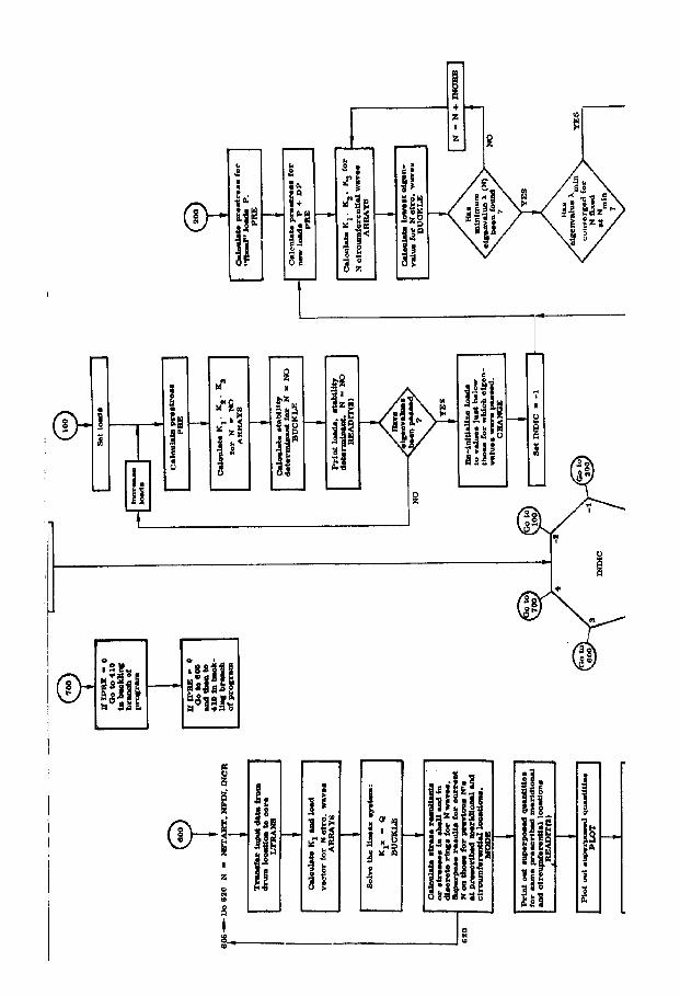
Overall control in BOSOR4 depends on the integer INDIC. The various types ofanalysis chosen by the input variable INDIC are listed in a previous section, and the flowof calculations for each value of INDIC is given in Fig. 13t. All of the input data are readin READIT. Figure 14 shows all of the subroutines called in this overlay, and Fig. 15 showsthe arrangement of a sample data deck. A call to READIT also causes results of calcul-ations to be printed out (OUTFIN). Some general data that pertain to the entire shell areread in first. Then, for each shell segment the mesh point distribution (MESH), meridiangeometry (GEOMTR), discrete ring properties (RGDATA), mechanical and thermal lineloads (LINELD), mechanical and thermal distributed loads (DISTL), and shell wallproperties (WALLS) are read in. The subroutine GASP, which is called in several places,causes certain data to be stored on and read from drum or disk. These data will be usedin the calculations to be performed in other overlays. The calculations in TIADI' areperformed in single precision. Overlay READIT has another important function-itcauses to be computed 'templates' of the stiffness, load-geometric, lambda-sjgred, andmass matrices for the nonsymmetric stress, buckling, and vibration problems and the
-EMIT
Fla. 11. Main link with overlays.
t Figur 13 appears fadng p. 424.
412

Stress. Stability and Vibration of Complex, B9ranched Shells of Revolution
MAN0~
A10000 -
-
If 20000
30000 * iiLmfl n40 READIT 'PE AAY5 BUCKLE PI4----
10000-
30000 -
READIT A READIT E r F L
a-------------------------------------- - ----- -BUKE--------- -
~.,,
0 4- MAIsWE N 1 -L
a3 P! O UCL
10000-
20000 R
0 0M
I-.
5000 201 READIT
FMo. 12. BOSOR4 core storage-qureients.
413
i

DAVID BusHNELL
stiffness matrix for the prebuckling problem. These 'templates' give the 'shapes' of the gov-erning equation systems. Examples are shown in Figs. 7-10.
The nonlinear stress analysis for axisymmetric behavior of axisymmetric systems isperformed in the overlay PRE. Data for shell and discrete ring properties, temperature andpressure distributions, and thermal and mechanical line loads are read into core from drumor disk (GASP); 'variable' loads are increased or decreased by appropriate increments ordecrements; the coefficient matrix and the 'right-hand-side' vector are derived for thecurrent Newton-Raphson iteration; the coefficient matrix is factored (FACTR); theequation system is solved (SOLVE); a test for convergence is made; and the prebucklingor prestress stress resultants and stresses are calculated from the converged displacementvector. These prestress quantities are stored on the drum or disk for later use in thebuckling and vibration analysis and for later plotting.
d3E
now
n- - Ix overL S tat i LiUT ft1 § - w KeAP - h
1* Fmt Am "TI
-W'C F~1 - xn MIDTmI
Nl is cute i E SE a E te lInarTEL~~~~- Loaw ||l9
Aiedr e Ag n l wer N D ini.M, , -W.E mm?33*E
pmzz
FIG. 14. READIT overlay.
In the next overlay (ARRAYS), the coefficient matrices corresponding to the buckling
analysis, vibration analysis, and linear symmetric and nonsymnietric stress analysis arederived. Subroutine ARRAYS is called for each value of the circumferential wave numberN. If INDIC=3, the load vector Q. is calculated in ARRAYS, and the linear system Klx
=Q is solved for the given circumferential wave number N. Depending on INDIC, variouscoefficient matrices are derived. With buckling analyses, for example, three matrices areobtained in ARRAYS for each circumferential wave number N: the stiffness matrix K,
for the composite shell, which corresponds to the structure loaded by the 'fixed' parts of
the loads, the 'load-geometric' matrix K 2 which contains linear powers of the eigenvalue
A, and the 'A"' matrix K 3 , which contains quadratic powers of A. In modal vibration
analysis, two matrices are derived in ARRAYS: the stiffness matrix K, for the prestressed
shell, and the mass matrix M. The arrays K 1 , K2 , K3, and M, are stored on drum or disk
in blocks of a given length for later use in overlay BUCKLE.
414

Stress, Stability and Vibration of Comp4;' Aranched Shells of Revolution
FiG. 15. Sample data deck.
The equation systems for the stability and vibration analyses are solved in the overlayBUCKLE. Subroutine BUCKLE is called for each value of the circumferential wavenumber N. The arrays derived in ARRAYS are read in from drum or disk.
If INDIC= I (linear buckling analysis) the eigenvalue problem
(K1 + AK 2+ PK 3){x}=0
is solved for the first NVEC eigenvalues with the correct sign (EBAND). In many structuralsystems, buckling is physically possible with loads of opposite sign than those actuallypresent. Therefore, in EBAND eigenvalues that are negative are not counted as 'accepted'roots. It is possible, for example, for the user to specify NVEC=3 and for more than threeeigenvalues to be obtained. The negative eigenvalues are given (printed out), and ortho-gonalizations are of course performed with respect to their associated eigenvectors; however,calculations will continue until the prescribed number (NVEC) of positive eigenvalues hasbeen determined. With INDIC=2 the eigenvalue problem to be solved for NVEC eigen-values is
(K1 -_l2 M){x}=O
in which M is the mass matrix. (M, incidentally, is not diagonal because u; and vf are at'half' stations, and discrete ring rotatory inertia is included.) This solution occurs in sub-routine EBAND2. The calculation of the lowest buckling load with nonlinear prebuckling
415

DAVID BUSHNELL
effects included (INDIC= -1) is performed in EIGEN. Figure 16 summarizes the typesof equations being solved for the various values of INDIC. All of these calculations (exceptfor INDIC=3) are performed in Overlay BUCKLE.
The functions of the other two overlays MODEI (MODE) and PLOTI (PLOT) aregiven in Fig. 13.
Some as for INOIC. | Cobb Stbity DermiESAND PACiR
Lineor Solution Ce-eus lewst Ebbedwa-of # ythe
KFx. Q S eNDIC I yl
Coluasted fin 2 IARmYS ttic-
Coloukite WadfNICChiteLuo NYICEkOWslM of ft Systm: EEieweas of *t Syde-mKtx - gesL x*O XjX*XX .1 >tt- *
EBAND2 EBAND
Flo. 16. Types of equations being solved for various INDIC.
ANALYTICAL RESULTS FROM BOSOR4
The remaining sections of the paper provide examples of the types of problems thatBOSOR4 is designed to handle. The first seven examples are for shells of revolution, andthe last two are for branched panels and columns. The first three and last two examples arefrom the BOSOR4 user's manual. The fourth, fifth, and sixth examples correspond to'real-world' engineering problems. The seventh example represents an illustration of someof the problems involved in a buckling analysis in which nonlinear effects are importantand in which eigenvalues are closely spaced. The examples are chosen to illustrate the seventypes of analysis governed by the control integer INDIC. Computer times given in the textare for Univac 1108 double precision calculations on the EXEC8 system.
Example 1. T-ring modeled as branched shell (INDIC= 1)
Figure 17 shows the discretized model and buckling loads predicted for a given rangeof circumferential waves N. BOSOR4 gives two minima in the range 2•N• 16. The mini-mum N=2 is a mode in which the cross-section does not deform-i.e. the ring ovalizationmode. Buckling pressures calculated for this mode are very close to those computed fromthe well-known formula q-,=EI(N2 - 1)/r', in which q,, is the critical line load in lb/in.(pressure integrated in the direction of segment 1), El is the bending rigidity of the ring, andr, is the radius to the ring centroidal axis. The minimum at about N= I I corresponds tobuckling of the web. Approximately 20 sec of CPU time were required for this case.
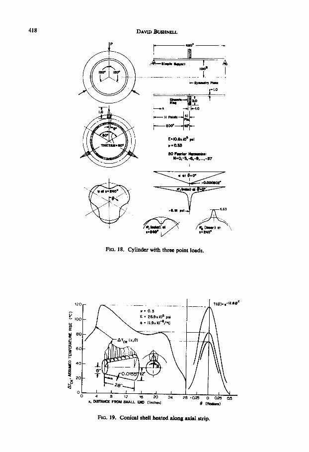
Example 2. Stress analysis of ring-stiffened cylinder with three-point loads (INDIC=3)Figure -18 presents the example with deflections and stresses shown schematically. The
threepoint loads are modelel as a line load with three triangular 'pulses' applied to thering. The results for stresses and displacements have apparently converged to a reasonablyaccurate value, since a 10-term Fourier expansion yields at 8=0: w= -0.000301 in.,
416

Stress, Stability and Vibration of Codtta, Branched Shells of Revolution
A A
O.We-.4 I.. S.. PoI,SECTION AA
E * 10.8 .S psi ® 10V- 0333 7
2400
2000 \
1200-(
9 00 /< 4llzltion: Ita * CaINS- 11T(
400 ':
0 4 C, a, W DaRaAENTIL HWE, N
FIG. 17. Buckling of ring treated as branched shell.
a, (outer)= -6.19 psi, and a2 (inner)=6.02 psi. Reduction of the number of points inthe 40-in. length near the ring from 41 to 11 with use of 20 Fourier harmonics gives at0=0: w=-0.000302 in., a, (outer)=6.30 psi, and a2 (inner)=6.56 psi. Similar smallchanges occur in the other variables. The reason that convergence with increasing numberof Fourier harmonics is better than expected is that the ring essentially 'integrates' theapplied load. It is for this reason that numerically one-dimensional shell-of-revolutioncodes based on Fourier superposition are frequently reliable and efficient for analysis ofshell systems submitted to concentrated loads. The very rapid convergence with increasingnumber of mesh points in the short segment near the ring is a property of the finite-differenceenergy method, see Ref. [28]. Approximately 33 CPU sec on the 1108 were required forexecution of the case described in Fig. 18. This includes time to plot six frames with aboutfifteen traces on each frame.
Example 3. Buckling of conical shell heated on axial strip (INDIC=4)Figures 19 and 20 show the model and results. Figure 19 gives the temperature rise
distribution at buckling as reported in Ref. [30]. Figure 20 shows the prebuckling stressand displacement distributions and the lowest three eigenvalues and eigenvectors corres-ponding to 20 circumferential waves. The eigenvalues denote a factor to be multiplied by theprebuckling temperature rise distribution. Twenty Fourier harmonics were used for theprebuckling analysis. The model consists of 309 degrees of freedom. A total of 74 sec ofCPU time on the 1108 were required for execution of the case.
417
DAVID BUSHNELL
-1--l.0
loon
-. SYMmelv Pk"
rA- 0-33
ZO Fourier HmIm
I. .
WI-6.51 Del 6.63
. wi/a of<S.-4iw1> A (1 mm) et l5.340"
FIG. 18. Cylinder with three point loads.
X. ISTANCE FROM SMALL END (Inches) 9 (ROOM )
FIG. 19. Conical shell heated along axial strip.
418
YCo
aW
II-:

Stress, Stability and Vibration of Complex, Branched Shells of Revolution
)l 1.141 X.LIS9Pin N-20 NeZO
LIS78"-D2
cILS MOMs I
FIG. 20. Prebuckling state of heated cone and buckling modes.
Example 4. Buckling of a corrugatedshroudunder max. q nonsymmetrlc airloads (INDIC=4)Figures 21-23 and Table 2 pertain to this case. Figure 21 gives SC4020 plots of the
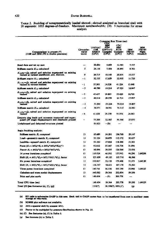
reference surface of the structure and some expanded views. Many of the ring stiffenersare treated as flexible shell structures. A discrete ring is shown as a centroid and an attach-ment point. Figure 22 shows details of how the modeling is done at a typical station. Figure23 shows a schematic of the assumed pressure distribution, taken essentially from wind-tunnel data. Also shown in Fig. 23 are computer-generated plots ofthe prebucklingdeformedstructure and a buckling mode corresponding to the prestress distribution on the leeward(axially compressed) side of the shroud. Table 2 gives comparative computer times forvarious intermediate computations on the Univac 1108, IBM 370/165, and CDC 6600. Themodel consists of 1033 degrees-of-freedom with a stiffness matrix maximum semibandwidthof 133. Five Fourier harmonics were used for the prebuckling analysis.
419
DAVID BUSHNELL
TABLe 2. Buckling of nonsymmetrically loaded shroud-shroud analyzed as branched shell with18 segments: 1033 degrees-of-freedom. Maximum semibandwidth: 133. 5 harmonics for stress
analysis
ComOr Run Times (sac)
6600 CDCUNIVAC FTN 6600 IBM
Circumfer- 1108 (OPT-I) RUN IBM 370/165Computatitns inprocos (4) ential EXEBC8 CO Wer Compiler 3701165 Bisn
(I 108 and MM 370 in doubke precasion) waves (CPU) (CPU) (CPU) (CPU) valuee(d)
Read data and set up case
Stiffness matrix Kio calculated
ijeox-Qe solved and solution superposed on existingvectors at various merldional, circ. stations.
Stiffness matrix Ki calculated
Ku xi-Qa solved and solution superposed on existingvectors at various stations
Stifsid Matrix Ks2 calculated
K12x2-.Qz solved and solution superposed on existingvectors
Stiffness matrix K, calculated
Kiax3-Qs solved and solution superposed on existingvecton
Stiffness matrix K,4 calculated
K14x4-Q4 solved and solution superposed on existingvectors
Discrete ring loads and moments computed and super-posed (29 ring) displacements and resultants printed
Undeformed and deformed structure plotted
Begin buckling analysis:
StUfbhess matrix Li computed
Load-eometrIc matrix Ki computed
Lambda-squared matrix K3 computed
Form (Ki + MUo4K + MUo*MAUo*)(e)
Factor K, + MUoOK + MUoMe*Uo*K14 power iteratlons completed
Shift (Kg + MU K *4 + MUt *MUs *A), factor
Six power iterations completed
Shift (Ki + MU*4K + MU2aMU2*aK), factor
Three power iterations completed
Calculate and store modal displacements
Print snd plot mode
Total CPU time (sec)
Total I/O le footnotes (e), (f), ()]
- 20.692 5.809 12.580
0 24.118 7.504 18.690
0 28.719
- 1 32.335
- 1 37.303
-2 40.780
-2 45.437
-3 48.914
- 3 53.505
-4 56.971
-4 61.628
10.160 26.836
11.859 32.930
14.528 41.224
16.216 47.320
18.885 55.620
20.578 61.714
23.234 70.014
24.941 76.110
29.370 91.976
- 75.205 32.305 99.366
81.025 -(b) -
13
13
13
13
13
13
13
13
13
13
13
13
85.689
91.354
93.382
93.832
98.096
118.824
123.600
132.017
136.367
140.741
145.882
149.654
34.291 106.760
36.079 115.172
37.024 118.200
37.167 118.734
39.555 126.064
46.592 157.942
49.102 165.710
52.128 179.408
54.631 187.178
56.156 195.190
59.364 202.854
-(b) 203.778
149.654 59.364 203.778
15.0(e) 38.100(e) 1051(f)
7.537
8.703
10.537
1 1.720
13.640
14.847
16.760
17.907
19.897
21.083
24.663
27.870
29.147
30.637
31.303
31.996
33.556
44.296 3.64256
46.566
51.373 3.64120
53.563
55.986 3.64123
59.330
59.330 3.64123
(d)
(a) 857 cM to Subroutine GASP in this cas Each call to GASP cause data to be traserred from core to auxiliary mestVAMP or vite-versa.
(b) SC4020 plot software not available
(c) MU -spectral shift by amount MUm.(d) Factor to be multiplied by pressure distribution shown in Fig. 23.
(e), (f) See footnotes (e), (f) in Table 3
(g) See footnote (h) in Table 3.
420
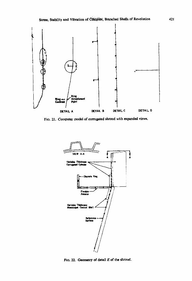
Stress, Stability and Vibration of ijle, Branched Shells of Revolution 421
RingRlq.- Attochment
)Cenfrldl pant
DETAIL A DETAIL E DETAIL C DETAIL D
FIG. 21. Computer model of corrugated shroud with expanded views.
VIWAAA j~ AVarle ThIckne-Corrptd CyupW I
No* ig\ 0
Variale TicknesMonocoque Conical Shll e
1e1erece,&Wh=Gn
FiG. 22. Geometry of detail E of the shroud.

DAVID BUSHNELL
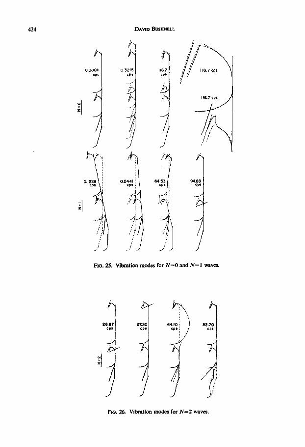
Example 5. Free vibration modes of a two-stage rocket (INDIC=2)The model is shown in Fig. 24, and the vibration modes are depicted in Figs. 25 and
26. The rocket is considered to be empty, so that the modes do not contain the effects offuel or payload. The first two modes for N=O and N= I circumferential waves are rigid-body modes. The first mode for N=O is simply a rotation about the axis of revolution.
FIG. 23. Pressure distribution on the shroud, prebuckling deflection, buckling mode.
B
I -
A
TWO-STAlEROCKET
DETAL A DETAIL D
FIG. 24. Two-stage rocket: discretized model.
422

Stress, Stability and Vibration of C6iIio1, Branched Shells of Revolution 423
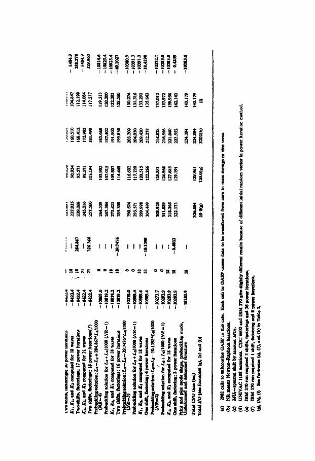
TAB3LE 3. Vibration of two-stage rocket treated as branched shell of 19 segments. Prestressanalysis: 536 degrees-of-freedom. Vibration analysis: 784 degrees-of-freedom. Maximum semi-
bandwidth in vibration analysis: 119, N=2 circumferential waves
Comput ations in procea(a)(I lOS nd IBM 370 in double precision)
Read data and set upPrestress soluton (NR-1)(b)Compute stiffne matrix K,Compute mas matrix K2Forn K, -MU, *K (shift)(9)Factor K, -MUKi2Fihst power iteration completedSecondThirdFourthFifthThirteen more power iterationsShift (Form K, -MU2*K2 )Factor KI -MU2*aK14 power itelns comented(U)Shn tform KI -MU3*J 3)Factor K, -MU3aK2Five power Iterations completedStore mode shape on drumFour power iteratIons, 2nd eigenvalueStore mode dshpe on drumTen power Iterations. 3rd eigenvalueShift (form KI -MU4
5 52) and factorFour power Iterations completedSevn power iterationsr 4th eigenvalueShift (form Xi -MU5*K2) and factorThee power Iterations completedSeven power iteration, 5th eigenvalueShift (form K, -MUe42) and factorThree power iterations completed14 power Iterations for 6th eigenvalueShift (form K, -MU7K2) and factorFont power iterations comptedCheck If all roote found (shiRft in and factor and count)Calculate and print out modesPlot undeformed and deformed structure, modes (28
frames)
Total CPU Time (seconds)Total 1|0 asee footnotes (e), (f). (h))
Computer Run Times (sec)CDC6600 CDC
UNIVAC FTN 6600 IBM1108 (OPT-I) RUN IBM 370)165
Frequency EXEC-$ Compiler Compier 370/165 Frequency(cps) (CPU) (CPU) (CPU) (CPU) (cps)
= 11.S10 3.049 3.310- 18.828 5.845 7.264
- 21.557 7.216 9.298- 22.227 7.573 9.712
- 22.660 7.688 9.944- 24.904 8.964 11.746
30.7808 25.594 9.219 12.17627.1542 26.297 9.472 12.60227.0698 26.991 9.722 13.02827.0683 27.6U8 9.977 13.45627.0653 28.380 10.227 13.88227.0159 37.600 13.492 19.434- 37.756 13.532 19.486- 40.058 14.808 21.286
26.8932 49.989 18.331 27.246- 50124 18.368 27.300- 52.424 19.649 29.100
26.8674 55.997 20.906 31.230- 56.012 20.910 31.234
27.2032 59.277 22.033 33.188- 59.297 22.039 33.192
64.0898 67.111 24.832 37.918- 69.337 26.148 39.772
64.0982 71.392 26.933 41.08682.6948 76.S08 28.981 44.548- 79.082 30.302 46.398
82.6958 81.189 31.092 47.724117.659 87.144 33.274 51.292- 89.514 34.593 53.144
117.657 91.693 35.392 54.4S6160.249 103.199 39.709 61.612- 105.309 41.028 63.462
160.086 108.167 42.089 65.242- 110.567 43.421 67.116- 119.363 45.945 69.776
- 126.530 -(d) -(d)
12630 45.45 609.77613.000(e) 44.071(e) 1209(f)
4.7107.1308.0508.3778.7409.5439.883
10.26310.60310.96311.34014.59714.86015.64317.83318.087
19.94719.95021.49721.50025.67326.73627.93630.56331.53332.6S335.93636.93638.09644.62345.63947.16648.91952.089
-(d)
52.089(h)
27.484427.018927.011027.008227.004426.9738
26.8685
26.8676
27.2031
64.0905
64.096382.6942
82.6962117.659
117.657160.046
160.085
(a) 1029 calls to subroutine GASP in this case. Each call to GASP causes data to be transferred from core to auxiliaryMaSa storage or vice-veraa.
b) NR me-n Newton-Raphson iterations.c) M Ug-spectral ahift by amount MU.d) SC4020 plot soflware not available.e) This is 'equivalent' n/o sec as chared at the particular installation where cam run. For the CDC 6600 FTN case
the actual 1/0 sec were about 100, but since the program required only 40 per cent of total core available, the charge(actual //O sec) was 0.44 times the charge/(CPU-4ec).
(f) Thi is the quantity of opetig tem (1/O) calls required at the NASA Lauloy CDC wham this case was run.Note: Quantity of call depends on the buffer size set by the user. 1500-t (decimal) is suggested.
( 6 orer iterations required on IBM 370/165.h) 1 charge depends upon size of buff., and upon record lengths established in the JCL and in Subroutine GASP.
o 1 2 0this as of the conversion of BOSOR4 to the iBMI370 had not been completed.
The two rigid-body modes for N= I are orthogonal to each other, but are each linear com-
binations of a uniform lateral translation and rotation about the center of mass. The third
mode for N=O is localized in the neighborhoods of the nozzles, and expanded plots are
given for clarification. Three of the modes involve local motion of the nozzles; the fourth
mode for N=1 and the first and second modes for N=2. This vibration model contains
784 degrees of freedom and the maximum semibandwidth of the stiffness matrix is 119.
Table 3 presents comparative data on computer CPU times for calculation of the six lowest
eigenvalues for N=2 circumferential waves.
DAvID BUSHNELL
0.00011cps
I
0.1229 1:
-I
0.3215cps
. .
'I
0.2441 l
C..
16.7cps
I
64.53cpI
IS;
6 -'1
116.7 eps
94.88cps
Fxo. 25. Vibration modes for N=O and N= I waves.
t)
2&67cps
CA
1•
27.20cps
64.10cps
82.10cps
Mwa. 26. Vibration modes for N=2 waves.
424
zl

~m P
if . .Ri0E > " -li
-iV . . . . . .A
f Ii I 4 I 1 II;
21$ ~ ~~~~~~~~~ ~ ~~~~ q V s< rt tC tqq< .'° tC
i~ v}1S
oovuteneuw~euwut W el4oa
.Ji - -'0x, -X2iX]! ,1,i !
iIS lE til! bil!
X - - - - - - - - - - - - - -
tltsa WIR -Au laff E
il I q-5 g aRR S fi" E a, I {I@ ii1
i-li USER #r no o
gw i'iI 14I , C-4 I I_1;o 0 et In A-
I11
I. - - - 0 00 t 00 00 a 0 0 a 0 an a.
t-.� 0) 0.�
� III �liii liii illi
�
� I�i�
1!1P141
2 v y �I � 'tt 9 lo ;;I ! g St I I at � g 4 � ;,' :., 1 2- -_ _- ;- R A ;; ;; t" A R A A 'In
16I
I
I* I
zI I
I I2 3
I Az I0
Ai I
i Iil
3 ~IIsM
I
I ~fI
I I I I I I I 14 11
z
Lzi
i
Ze
Li

N
Z,
+P.
z
Alan]
IRAM
Stress, Stability and Vibration of Complex, branched Shells of Revolution
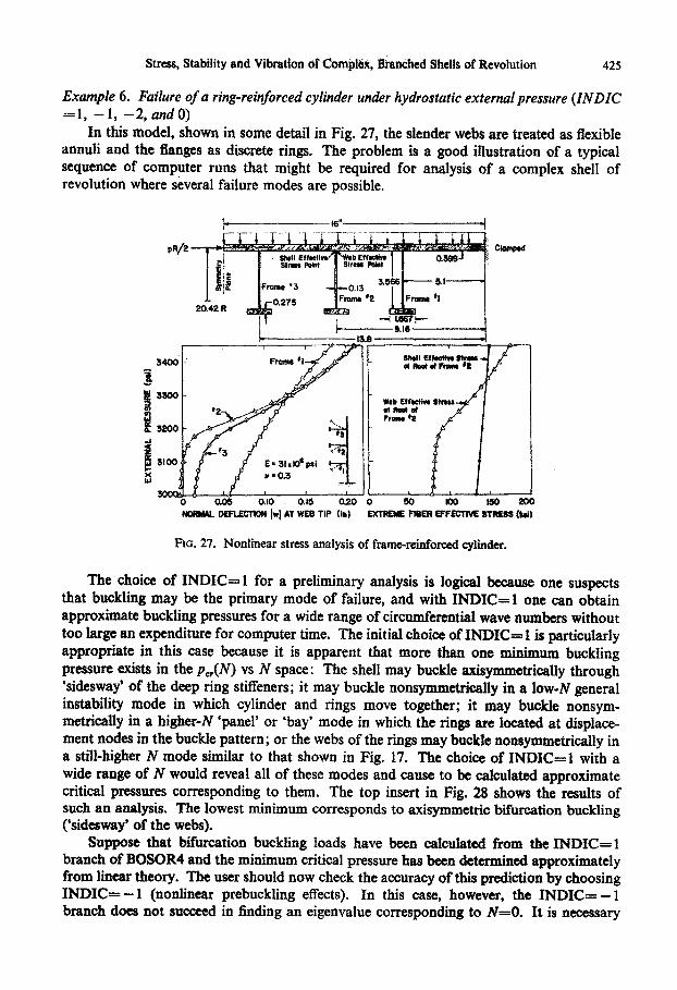
Example 6. Failure of a ring-reinforced cylinder under hydrostatic external pressure (INDIC-1,-1, -2, andO)
In this model, shown in some detail in Fig. 27, the slender webs are treated as flexibleannuli and the flanges as discrete rings. The problem is a good illustration of a typicalsequence of computer runs that might be required for analysis of a complex shell ofrevolution where several failure modes are possible.
* i! Effedtive b tv l gg
|Foramre 13 -0Lo13 356 5.1 -
0.275 F2 Prame2 1Fram I
a Neat at ee.
at9ct.163400 ' Frame 'I Shame 'tt S y
E3300 W b Effete staff I
#2 , ofi f2 ofI
t3200 L
1'UX3100 E3t.a0psi 4
0 0.0a Ol0. 0.15 0.20 0 50 100 150 200NORMAL DEFLECTION 1wl AT WEB TIP (in) EXTRE FiBER EFFECTIVE STRESS We)
FIG. 27. Nonlinear stress analysis of frame-reinforced cylinder.
The choice of INDIC= I for a preliminary analysis is logical because one suspectsthat buckling may be the primary mode of failure, and with INDIC= 1 one can obtainapproximate buckling pressures for a wide range of circumferential wave numbers withouttoo large an expenditure for computer time. The initial choice of INDIC= I is particularlyappropriate in this case because it is apparent that more than one minimum bucklingpressure exists in the pe,(N) vs N space: The shell may buckle axisymmetrically through'sidesway' of the deep ring stiffeners; it may buckle nonsymmetrically in a low-N generalinstability mode in which cylinder and rings move together; it may buckle nonsym-metrically in a higher-N 'panel' or 'bay' mode in which the rings are located at displace-ment nodes in the buckle pattern; or the webs of the rings may buckle nonsymmetrically ina still-higher N mode similar to that shown in Fig. 17. The choice of INDIC= I with awide range of N would reveal all of these modes and cause to be calculated approximatecritical pressures corresponding to them. The top insert in Fig. 28 shows the results ofsuch an analysis. The lowest minimum corresponds to axisymmetric bifurcation buckling('sidesway' of the webs).
Suppose that bifurcation buckling loads have been calculated from the INDIC= 1branch of BOSOR4 and the minimum critical pressure has been determined approximatelyfrom linear theory. The user should now check the accuracy of this prediction by choosingINDIC= -1 (nonlinear prebuckling effects). In this case, however, the INDIC= -1branch does not succeed in finding an eigenvalue corresponding to N=O. It is necessary
425

DAVID BUSHNELL
2.5j
2.0 -C1 d.
'.5
1.0
jO.
.002200 2400- OOw 280-0 300 20 3400
EXTERMIL PRiESSURE (psi)
Fio. 28. Linear (INDIC=l) and nonlinamr(INDIC= -2) bifurcation buckling analyses of frame.-reinforced cylinder,
to choose INDIC= - 2 ('plot' stability determinant) to find out why. Figure 28 showsresults of the INDIC= - 2 analysis. At a pressure close to the bifurcation pressure withINDIC= 1, the stability determinant changes direction rather abruptly, indicating fairlylarge changes in prebuckling deformations for small changes in pressure. Since the stabilitydeterminant does not change sign, it is not surprising that the INDIC= - I branch failsto find an eigenvalue. A final computer run with INDIC==0 gives axisymmetric nonlineardisplacements and stresses for increasing pressure. The results of the IND)IC=0 analysisare shown in Fig. 27. The rather abrupt increase in rate of 'sidesway' in fr-ames No. 2 andNo. 3 bectween 3,100 and 3,200 psi is the cause of the change in direction of the stabilitydeterminant shown in Fig. 28. Failure of the structure would probably occur at the rootof frames No. 2 or No. 3 because of high (and rapidly increasing) Stresses there.Example 7. Buckling of very thin cylinder under axial compresirion (INDIC= - 1)
This example is included because nonilmear prebuckling effects are fairly important; itis a difficult case from a numerical point of view, since eigenvalues are close together andclose to the axisymmetric collapse load; and the case demonstrates some of the internalchecks and automatic internal control in BOSOR4. Because of these properties it is one ofthe cases that a previous program, the BOS0R3, could not handle very well.
Figure 29 shows the model of a cylinder with radius R=500 in., thickness t-lin.,length L=2,OOD in., Young's modulus E- 101 psi and Poisson's ratio v=0.3. The cylinderis treated as being symmetric about the midlength, and the 1,000-in, half-cylinder thusanalyzed is divided into two segments: a 200-in.-long edge zone segment with 83 mesh
426

Stress, Stability and Vibration of CombWh; Branched Shells of Revolution
Nai
Prbuckflng--DeOrmations
1174 lbs/In
FIG. 29. Buckling of axially compressed cylinder.
points, and an 800-in.-long interior segment with 99 mesh points. The axisymmetric pre-
stress model thus contains 379 degrees-of-freedom, and the stability model 566 degrees-of-
freedom. Simple support conditions are applied at the edge, and symmetry conditions at
the midlength. Also shown in Fig. 29 are the prebuckling displacement distribution at the
predicted critical load of 10,274 lb/in. and the buckling mode corresponding to N= 18
circumferential waves.
With the INDIC= -1 option the user supplies a starting load, a starting range of N,
and an initial value of N. Through a sequence of operations the program first searches
for an approximate local minimum buckling axial load VY,(N) within the given range of N.
Once the N corresponding to the approximate minimum V4, has bee found, N becomes
fixed and a sequence of eigenvalue problems is established through which a final accurate
buckling load is computed at that value of N with nonlinear prebuckling effects accounted
for.
Figure 30 shows the sequence of wave numbers and loads automatically explored by
BOSOR4 to obtain the final result L6= V,,= 10,274 lb/in. With an initial base or 'fixed'
load of 0 and a 'variable' load (quantity to be multiplied by eigenvalue) of 1.0 lb/in.,
eigenvalues labeled (1), (2), (3), and (4) are calculated. The base or 'fixed' load is then set
equal to the local minimum or 12,008 lb/in. The 'variable' or 'eigenvalue' load is set equal
to 12,008/1,000 lb/in. The small increment over a relatively large fixed value gives an
accurate approximation of the 'local' rate of change of prebuckling stresses and rotations
with load-local change about a given base or 'fixed' point. This technique permits for-
mulation of another eigenvalue problem analogous to that represented by equation (1),
in which K1 is the stiffness matrix for N= 12 waves, including the effects of the 'fixed'
preload L 2 = 12,008 lb/in., and K2 and K3 are the load-geometric and lambda-squared
matrices. These matrices depend on various parameters as well as on the differences
between the prebuckling stress resultants and rotations at the 'fixed' load and those at the
load L 2 +L 2 /1,000. For this problem, the eigenvalue A is the factor that, when multiplied
427

DAVW BUSHNELL
2000 B o u
"id - / Li "~
m 11500 - osto Load *84 ltbs/k
co
o 10500 -
Final Predicted L *o -Le.,'
100009 12 15 la 21
NUMBER OF CIRCUMFERENTIAL WAVES
Fo. 30. Sequence of axial load and circumferential wave number estimates during calculation ofbuckding of cylinder with nonlinear prebuckling effects included.
by the load difference L2 /1,000, gives the quantity that must be added to the base or 'fixed'load L 2= 12,008 to give a new base load. A third eigenvalue problem at N= 12 can thenbe set up corresponding to the new base load. Ordinarily, calculations would continue inthis manner until A is smaller than a certain prescribed amount.
In this case, however, it is determined by BOSOR4 that for N=12 circumferentialwaves, three eigenvalues exist below the 'fixed' load 12,008 lb/in. Hence, the load is auto-matically reduced by a factor of 0.7 to 8,414 lb/in. With the eigenvalues corresponding topoints 5, 6, 7 and 8 and 9 in Fig. 30 determined, the new base load L 3 = 10,819 lb/in.is established corresponding to N= 18 waves. It is also determined by BOSOR4 that atN= 18 one eigenvalue exists below this new base load. However, the new load need notbe reduced by some factor because initial inverse power iterations for the eigenvaluenearest to L3 = 10,819 indicate that subsequent critical load estimates will further reducethe base loads L4 , Ls, etc., to the lowest eigenvalue rather than increase them towardthe second eigenvalue. Figure 30 shows the final three load estimates, L4 , LS, and L6 .
Table 4 identifies various computations and gives current 'fixed' loads, circumferentialwave numbers, eigenvalues, and CPU computer times. Underlined eigenvalues representvalues to which the inverse power iterations with spectral shifts converge. This particularcase requires much more than the average computer time for a nonlinear buckding analysiswith the same number of degrees of freedom for the following reasons:
(I) The eigenvalues for each N are closely spaced, so that many inverse power iter-ations and spectral shifts are required for convergence.
(2) The eigenvalues are close to the axisymmetric collapse load of the cylinder.Rapidly changing nonlinear behavior in the neighborhood of the eigenvaluescauses the requirement for more than the average number of base loads (LI-L 6 )with associated reformulations of the eigenvalue problem.
(41 ,-}
11-y)
428

Stress, Stability and VibratiOn of Codlnj J, franhed Shells of Revolution
Figure 31 shows the prebuckling load deflection curve for this cylinder. The abscissarepresents the difference between the actual end shortening and the end shortening thatwould exist if there were no prebuckling rotations. Eigenvalues computed with the INDIC= +1 branch for N= 18 waves are shown as crosses. Several runs were made, each runcorresponding to a different base or 'fixed' load. The open circles correspond to the variousbase loads, Li. The large dots represent the 'fixed' loads used in the sequence shown inFig. 30. Two to four eigenvalues are calculated corresponding to each open-circle base
-, 1lO t500 i.' 1900 Ibs/in *-M.~----- ----- ------------------ [---- F,/r
2 0 '' 42008 lbs/in
11000
x9
1'.lk,.0379
102 IO74
9000
8 , -L 8414 lb*/in
<8000.
Fia. 31. Eigenvalue 'separation' for axially compressed cylinder.
429
DAvmD BueL
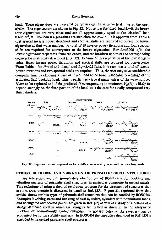
load. These eigenvalues are indicated by crosses on the same vertical lines as the opencircles. The eigenvectors are shown in Fig. 32. Notice that for 'fixed' load L=O, the lowestfour eigenvalues are very close and are all approximately equal to the 'classical' load0.605 EtV/R. The lowest eigenvalues are also close for N= 15. It is apparent from Table 4that several inverse power iterations and spectral shifts are required to obtain the lowesteigenvalue at that wave number. A total of 39 inverse power iterations and four spectralshifts are required for convergence to the lowest eigenvalue. For L=5,000 lb/in. thelowest eigenvalue 'separates' from the others, and the localized nature of the correspondingeigenvector is strongly developed (Fig. 32). Because of this separation of the lowest eigen-value, fewer inverse power iterations and spectral shifts are required for convergence.From Table 4 for N= 15 and 'fixed' load L3=8,422 lb/in. it is seen that a total of twentypower iterations and two spectral shifts are required. Thus, the user may save considerablecomputer time by choosing a base or 'fixed' load to be some reasonable percentage of theestimated final buckling load. This is particularly true if many values of the wave numberN are to be explored and if the predicted N corresponding to minimum Vr(N) is likely todepend strongly on the fixed portion of the load, as is the case for axially compressed verythin cylinders.
EIGENVECTOR~S____ ___
Prelood FIRST SECOND THIRD FOURTH(fbs.in.) A - \ 7 X , d
NC,,I2178 N, -12232 ' N,,' 122968- N,,'12357-
5000 /jf t17lO '-'2311780 123
8414 / ''< *f '-+ - z X84 080- 12190 228-5
10000 -10289- 11844- 2257 12360-
-110 11340 2253 a .
1150011329
11900A
11800 12202
Fio. 32. Eigenvectors and eigenvalues for axially compressed cylinder with various base loads.
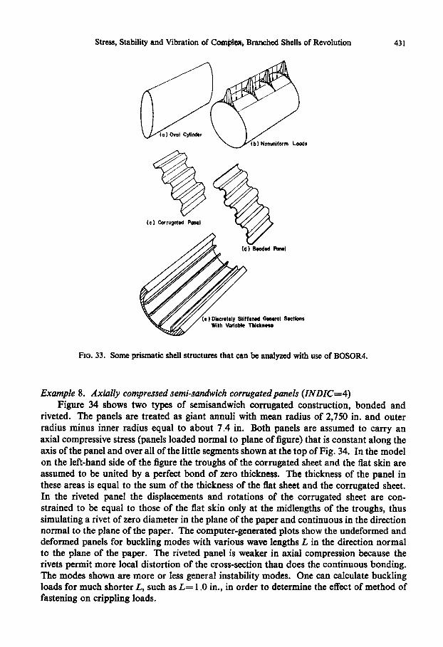
STRESS, BUCKLING AND VIBRATION OF PRISMATIC SHELL STRUCTURESAn interesting and not immediately obvious use of BOSOR4 is for buckling and
vibration analysis of prismatic shell structures, in particular composite branched panels.This technique of using a shell-of-revolution program for the treatment of structures thatare not axisymmetric is discussed in detail in Ref. [25]. Figure 33, reprinted from thatarticle, shows various types of prismatic shell structures that can be handled by BOSOR4.Examples involving stress and buckling of oval cylinders, cylinders with nonuniform loads,and corrugated and beaded panels are given in Ref. (25] as well as a study of vibration of astringer-stiffened shell in which the stringers are treated as discrete. In the analysis ofbuckling of nonuniformly loaded cylinders, the nonsymmetry of the prestress can beaccounted for in the stability analysis. In BOSOR4 the capability described in Ref. [251 isextended to branched prismatic shell structures.
430
Stress, Stability and Vibration of Complx, Branched Shells of Revolution
Loads
t) Discretely Stiffened General SectionsWith Variable Thickness
FiG. 33. Some prismatic shell structures that can be analyzed with use of BOSOR4.
Example 8. Axially compressed semi-sandwich corrugatedpanels (INDIC=4)Figure 34 shows two types of semisandwich corrugated construction, bonded and
riveted. The panels are treated as giant annuli with mean radius of 2,750 in. and outerradius minus inner radius equal to about 7.4 in. Both panels are assumed to carry anaxial compressive stress (panels loaded normal to plane of figure) that is constant along theaxis of the panel and over all of the little segments shown at the top of Fig. 34. In the modelon the left-hand side of the figure the troughs of the corrugated sheet and the flat skin areassumed to be united by a perfect bond of zero thickness. The thickness of the panel inthese areas is equal to the sum of the thickness of the flat sheet and the corrugated sheet.In the riveted panel the displacements and rotations of the corrugated sheet are con-strained to be equal to those of the flat skin only at the midlengths of the troughs, thussimulating a rivet of zero diameter in the plane of the paper and continuous in the directionnormal to the plane of the paper. The computer-generated plots show the undeformed anddeformed panels for buckling modes with various wave lengths L in the direction normalto the plane of the paper. The riveted panel is weaker in axial compression because therivets permit more local distortion of the cross-section than does the continuous bonding.The modes shown are more or less general instability modes. One can calculate bucklingloads for much shorter L, such as L= 1.0 in., in order to determine the effect of method offastening on crippling loads.
431
DAVID BUSHNELL
SONCED PANEL
( -) Fite Diffwre MO"
tb1 L- *32 chs N-0.943
(c) L 1 incchne N'O.T5
.. .......... ..
to)- L *les -*OA*
DETAIL A
RIVETED PANEL
(el MOh Cltthum Modal
(b) L.32 inchs N-Q.66
(ci L.16 -ilcs N- Q533
I s *.'.I :
(d1 L l 1067 InctM N * 0.4s6
.to) L'S Iliew, N .. 4t1
RIVET %
DETAIL 3
L * Ail Helu-Wviio of Sudilg Mode N * (Critial Aoal Lodt/CII Axia Loog With Local/Di W( ofWll u.olm NO AUlwod)
FIo. 34. Buckling modes of axially compressed semisandwich bonded and riveted corrugated panels.
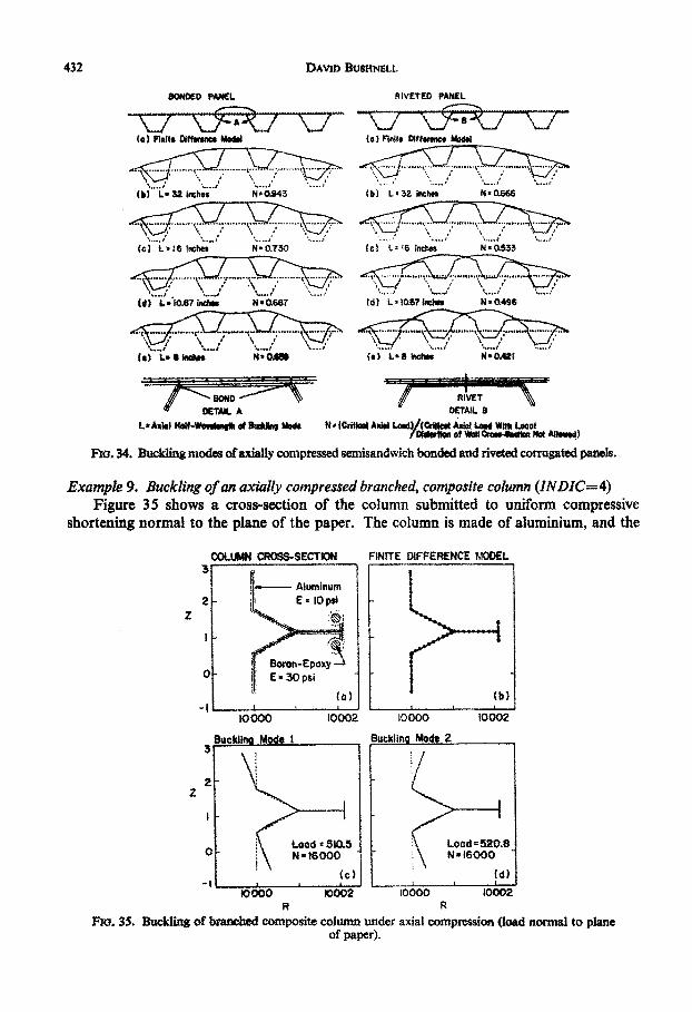
Example 9. Buckling of an axially compressed branched, composite column (INDIC=4)
Figure 35 shows a cross-section of the column submitted to uniform compressive
shortening normal to the plane of the paper. The column is made of aluminium, and the
COLUMN CROSS-SECTION FINITE DIFFERENCE NWEL
Aluminum
2 - E ' IOpsiz
|' BoronE-poxyo E 30psl
-It0000 10002 10000 10002
Buckin e 1 Su kII Mode 2
2
R RFro. 35. Buckling of branched composite column under axial compression (load normal to plane
of paper).
432

Stress, Stability and Vibration of Compi, Branched Shells of Revolution
circular appendages attached to the short flange are filled with boron epoxy composite.The column is treated as a shell of revolution, with radius from the axis of revolution to thetwo 'foot' flanges equal to 10,000 in. The mesh-point distribution is shown in Fig. 35b,and two buckling modes corresponding to an axial half-wavelength of 10,000 x r/N=1.96 in. are shown in Fig. 35c and d. These modes represent antisymmetric and sym-metric crippling of the foot flanges. The critical 'loads' 510.5 and 520.8 are actuallyeigenvalues, quantities to be multiplied by the loads per length along the cross-section ofthe column, which for this INDIC=4 run are read from cards as input data.
SUMMARYThe paper gives a complete description of the BOSOR4 computer program, which
runs on the CDC 6600, UNIVAC 1108, and IBM 370/165 computers. The literature oncomputer programs for shells and solids of revolution is briefly reviewed. BOSOR4 andother computer programs are shown in a 'capability' chart. The basic assumption uponwhich BOSOR4 rests are enumerated, and the finite-difference energy method is described.The formulation of the stability problem is shown, and the strategy is demonstrated forobtaining the lowest buckling load in cases for which the eigenvalues are closely spacedand the problem is highly nonlinear at loads in the neighborhood of the bifurcation buckling.Examples of stiffness matrices for branched systems of shells are shown. Overlay chartswith required core storage are given for operation of BOSOR4 on the CDC6600, UNIVAC1108, and IBM 370/165. A schematic of a typical data deck is shown. Flow charts aregiven for the seven types of analysis that BOSOR4 will perform: buckling with nonlinearprebuckling, nonlinear axisymmetric stress, buckling with linear prebuckling, vibrationwith nonlinear axisymmetric prestress, linear nonsymmetric stress with automatic cal-culation of Fourier series of nonsymmetric loads and automatic superposition of harmonics,buckling with linear nonsymmetric prestress, and calculation of stability determinant foran increasing sequence of applied loads. Examples are given for each of these types ofanalysis with central processor times given on the CDC, UNIVAC, and IBM computersfor the various operations during the execution of three typical rather large cases. Theuse of BOSOR4 for the calculation of buckling loads of branched, prismatic shell structuressuch as a semi-sandwich corrugated panel is demonstrated.
Acknowledgements-The author is indebted to Frank Brogan, Tom Peterson, Chet Dyche, Bo Almroth,Bill Loden, and Rod Kure, who wrote some of the subroutines used in the BOSOR4 program. Particularappreciation is expressed for the many fruitful discussions with Frank Brogan and Bo Almroth concerningthe numerical aspects of the analysis, and with Jbrgen Skogh about ways in which to make the BOSOR4program easy to use. The author is thankful also for Frank Brogan's assistance in the conversion ofBOSOR4 for operation on the CDC 6600 and Tom Peterson's, Pete Smolenski's, and Bob Mitchell'sassistance in the conversion for operation on the IBM 370/165.
The development of BOSOR4 was sponsored by the Department of Structural Mechanics of theNaval Ship Research and Development Center under Naval Ship Systems Command, Operation andMaintenance Navy Fund, Contract N00014-71-C-0002. Rembert Jones and Joan Roderick were technicalmonitors. The work involved in converting BOSOR4 for operation on the CDC 6600 was sponsored by theNASA Langley Research Center, Contract NASI-10929, with Paul Cooper as technical monitor.
Some of the numerical studies were performed under the Lockheed Missiles & Space Company'sIndependent Research Program.
REFERENCESt11 D. BUSHNELL, Stress, stability, and vibration of complex branched shells of revolution. Analysis and
User's Manual for BOSOR4. Lockheed Missiles & Space Company, Inc., LMSC-D243605, Sunnyvale,California (March 1972). Also NASA CR-2116 October (1972).
[21 G. A. COHEN, Computer analysis of ring-stiffened shells of revolution. Langley Research Center,NASA CR2085, Hampton, Virginia, September (1972).
433

DAVID BUSHNELL
[3] A. P. CAPPILLI, T. S. Nxumaro and P. P. RADicowSitI, The analysis of shels of revolution havingarbitrary stiffness distribution. Proc. AIAA/ASME 8th Structures, Structural Dynamics and MaterialsConference, pp. 732-749, Palm Springs, California, (1967).
[4] R. M. JoNEs and J. G. CaOs, SAAS II, finite element stress analysis of axisymmetric solids withorthotropic, temperature-dependent material properties. TR-0200 (S4980)-1, SAMSO TR-68-455,Aerospace Corporation, San Bernardino, California, September (1968).
[51 N. A. CYR and R. D. TErra, Finite element elastic-plastic-creep analysis of two-dimensional con-tinuum with temperature-dependent material properties. National Sympouium on ComputerizedStructural Analysir and Design, George Washington University, Washington, D.C., 27-29 March (1972).
[61 M. B. MARLOWE, FARSS User's Manual. Fourier analysis of rotationally symmetric solids. LockheedMissiles & Space Company, Inc., Sunnyvale, California, Report (1972).
[7] S. GHosH and E. L. WAON, Dynamic stress analysis of axisymmetric structures under arbitrary loading.Earthquake Engineering Research Center, Report EERC 69-10, University of California, Berkeley,California, September (1969).
[81 E. L. WisoN, L. R. Jonms and T. HsusH, Large displacement analysis of axisymmetric shells, structuresand materials research. Report 69-13, University of California, Berkeley, March (1969).
[9) M. KOSAf -BAKwI , Analysis of elastic-plastic shells of revolution under axisymmetric loading byfinite element method. Ph.D. Dissertation. Structures and Materials Research Report 67-8, Dept. ofCivil Engineering, University of California, Berkeley (1967).
[10] P. SHARI and E. D. Popov, Refined finite clement analysis of elastic-plastic thin shells of revolutionStructural and Materials Research Report 69-28, University of California, Berkeley, December (1969)
[ill H. S. LevINE, H. AXu}N, JR., R. WINIER and A. Pwico, Nonlinear behavior of shells of revolutionunder cyclic loading. National Symposium on Computerized Structural Analysis and Deugn, GeorgeWashington University, Washington, D.C., 27-29 March (1972); Grumman Research DepartmentReport RE-426J, Bethpage, Now York, April (1972).
1121 S. YAGHum, Incremental analysis of large deformation in mechanics of solids with applications toaxisymmetric shells of revolution. Structures and Materials Research Report 68-17, University ofCalifornia, Berkeley, December (1968).
[131 D. S. MARGoLoS, The effect of external loading on the natural frequencies of paraboloidal shells.Ph.D. thesis, University of Southern California, Los Angeles (1970).
[14] H. M. ADELMAN, D. S. CATHEuINE and W. C. WALTON, A method for computation of vibration modesand frequencies of orthotropic thin shells of revolution having general meridional curvature. NASATN D4972, Langley, Virginia, January (1969).
[151 T. HsuEN and E. L WhaoN, Stabity analysis of axisymmetric shells. Structures and Materials ResearchReport 69-22, University of California, Berkeley, September (1969).
[161 P. UNDERwooD, Transient response of inelastic shells of revolution. National Symposiwn on Com-pterised Structural Analyxis iad Design, George Washington University, Washington, D.C., 27-29Murch (1972); Lockheed Missiles & Space Company, Inc., Report, LMSC-D244589, Sunnyvale,California, November (1971).
[171 R. E. BALL, A computer program for the geometrically nonlinear static and dynamic analysis ofarbitrarily loaded shells of revolution, theory and user's manual. NASA CR 1987, National Aero-nautics and Space Administration, Washington, D.C., April (1972).
[181 1. LEsnmoi and J. PADOVAN, Numerical analysis of anisotropic rotational shells subjected to non-symmetric loads. Natinal Sympoafum on Computerized Structural Analysis and Des4n, GeorgeWashington University, Washington, D.C., 27-29 March (1972).
[191 J. C. GERDEeN, F. A. SImONEN and D. T. HuNTER, Large deflection analysis of elastic-plastic shellsusing numerical integnation. AIAA J. 9, (6), 1012-1018 (1971).
[201 R. F. HARTUNG, An assessment of current capability for computer analysis of shell structures. J.Computers & Structures 1, 3-32 (1971).
[21] R. F. HARTuNO, An assessment of current capability for computer analysis of shell structures. AirForce Flight Dynamics Laboratory, AFFDL TR 71-54, April (1971).
[221 D. BusmN u, Computer analysis of shell structures, ASME Paper No. 69-WA/PVP-13, November(1969).
[23] R. E. FULTON, Numerical analysis of shells of revolution. Proc. Synmposium of Internatdonal Union ofTheoretical and Applied MechanIcs, pp. 292-319, Liege, France, August (1970).
[24] J. A. SnucICuN, Geometrically nonlinear static and dynamic analysis of shells of revolution. Proc.Symposium of International Union of Theoretical and Applied Mechanics, pp. 383-411, Liege, France,August (1970).
1251 D. Busau., Stress, budding, and vibration of prismatic shells. AMAA 1. 9, (10), 2004-2013 (1971).[261 D. Busau.N , B. 0. Aamon and F. BRooAN, Finite-diffVeence energy method for nonlinear shell
analysis, J. Computers & Structures 1, 361-387 (1971).[27] D. Bumqimi, Analysis of ring-stiffened shells of revolution under combined thermal and mechanical
loading. AIAA J. 9, (3), 401-410 (1971).
434

Stress, Stability and Vibration of Comple. Branched Shells of Revolution 435
[281 D. BUSHNELL, Finite-difference energy models versus finite-element models: two variational approachesin one computer program. Presented at ONR International Symposium for Numerical and ComputerMethods In Structural Mechanics, Urbana, Illinois, September (1971).
(291 M. S. ANDERSON, R. E. FULTON, W. L. HEARD, JR. and J. E. WALz, Stress, buckling, and vibrationanalysis of shells of revolution, computer-oriented analysis of shell structures. Air Force FlightDynamics Laboratory, AFFDL-TR-71-79, pp. 1173-1246, June (1971).
(301 D. BUSHNELL and S. SMITH, Stress and buckling of nonuniformly heated cylindrical and conical shells.AIAA J. 9, (12), 2314-2321 (1971).
(Received 11 August 1972)


![Free vibration analysis of piezoelectric cylindrical nanoshell ......vibration analysis of shallow shells [25]. Loy et al. presented the free vibration analysis of cylindrical shells](https://static.fdocuments.us/doc/165x107/5f736ba706f884064751d11e/free-vibration-analysis-of-piezoelectric-cylindrical-nanoshell-vibration.jpg)


![Discrepancies Between Free Vibration of FML and Composite ... › article_3773_60f53b5298b... · cally cylindrical shells [3- 12]. Zhang [13] obtained the natural frequencies of laminated](https://static.fdocuments.us/doc/165x107/5f0441ba7e708231d40d14d2/discrepancies-between-free-vibration-of-fml-and-composite-a-article377360f53b5298b.jpg)