
Stress Analysis of Shrink-fitted Cylinder Head and Valve...
12
Vol-1 Issue-4 2015 IJARIIE-ISSN(O)-2395-4396 1372 www.ijariie.com 586 Stress Analysis of Shrink-fitted Cylinder Head and Valve Guide Connections via Finite Element Analysis N. A. Katait 1 , D.P. Hujare 2 1 Research scholar ME student, Department of Mechanical Engineering, Maharashtra Institute of Technology, Pune, Maharashtra, India 2 Professor, Department of Mechanical Engineering, Maharashtra Institute of Technology, Pune, Maharashtra, India ABSTRACT In an internal combustion engine, the cylinder head rests on the top of the cylinder block. One of the parts of head assembly is the valve guide, which is used to orient the valves correctly. Typically valve guide is made up of cast iron and fitted in cylinder head with the use of interference fit. The study aims to find the stress developed due to interference fit in valve guide and cylinder head of air cooled diesel engine. This is done using 3D simulation model and FEA. The investigation aims to provide the design intent to resolve valve guide loosing issue in operating temperature ranges. . Keyword: - Valve Guide, Cylinder Head, Interference Fit, Contact Pressure, FEA 1. INTRODUCTION In an internal combustion engine, the cylinder head sits above the cylinder block and it closes in the top of the cylinder, forming the combustion chamber. It is made up of aluminium and its alloy. One of the parts of head assembly is the valve guide, which is used to orient the valves correctly. Typically valve guide is made up of cast iron. This paper investigates the assembly of parts having a negative clearance, called interference, press or force fits. These types of fits are also commonly used for assembling bearing, attaching gear or sprockets to shaft, inserting dowel pin into hole. The Finite Element Method (FEM)-based stress analysis of interference-fitted connections is more complete and accurate than those obtained from the traditional methods. The finite element model determines for the stresses in the axial direction, which usually are not considered in the traditional design method.[1] There are various parameters which affect on contact pressure(stress) and hoops stress like thickness of valve guide, stiffness of cylinder head (G/D ratio), material of valve guide, and material of cylinder head. This is done for different interference fit and operating temperature range. From previous study it is shown that, thickness of valve guide and stiffness of cylinder head are the main parameter which affects a lot. These parameters are changing for minimum and maximum interference fit for operating temperature range. 2. LITERATURE REVIEW Y. Zhang et al. [1] has studied interference fit via FEM. In their studies of interference fits in ring gear-wheel connections show that the traditional design method based on thick-wall cylinder theory had some limitations. Lame's equations did not give good results for the interference stresses and deformations. This is because of the complex geometry of the problem, which involves a thin ring on a hollow, stepped shaft that protrudes unspecified,
Transcript of Stress Analysis of Shrink-fitted Cylinder Head and Valve...

Vol-1 Issue-4 2015 IJARIIE-ISSN(O)-2395-4396
1372 www.ijariie.com 586
Stress Analysis of Shrink-fitted Cylinder Head
and Valve Guide Connections via Finite
Element Analysis N. A. Katait
1, D.P. Hujare
2
1Research scholar ME student, Department of Mechanical Engineering, Maharashtra Institute of
Technology, Pune, Maharashtra, India 2Professor, Department of Mechanical Engineering, Maharashtra Institute of Technology, Pune,
Maharashtra, India
ABSTRACT
In an internal combustion engine, the cylinder head rests on the top of the cylinder block. One of the parts of head
assembly is the valve guide, which is used to orient the valves correctly. Typically valve guide is made up of cast
iron and fitted in cylinder head with the use of interference fit. The study aims to find the stress developed due to
interference fit in valve guide and cylinder head of air cooled diesel engine. This is done using 3D simulation model
and FEA. The investigation aims to provide the design intent to resolve valve guide loosing issue in operating
temperature ranges.
.
Keyword: - Valve Guide, Cylinder Head, Interference Fit, Contact Pressure, FEA
1. INTRODUCTION
In an internal combustion engine, the cylinder head sits above the cylinder block and it closes in the top of the
cylinder, forming the combustion chamber. It is made up of aluminium and its alloy. One of the parts of head
assembly is the valve guide, which is used to orient the valves correctly. Typically valve guide is made up of cast
iron. This paper investigates the assembly of parts having a negative clearance, called interference, press or force
fits. These types of fits are also commonly used for assembling bearing, attaching gear or sprockets to shaft,
inserting dowel pin into hole. The Finite Element Method (FEM)-based stress analysis of interference-fitted
connections is more complete and accurate than those obtained from the traditional methods. The finite element
model determines for the stresses in the axial direction, which usually are not considered in the traditional design
method.[1]
There are various parameters which affect on contact pressure(stress) and hoops stress like thickness of valve
guide, stiffness of cylinder head (G/D ratio), material of valve guide, and material of cylinder head. This is done for
different interference fit and operating temperature range. From previous study it is shown that, thickness of valve
guide and stiffness of cylinder head are the main parameter which affects a lot. These parameters are changing for
minimum and maximum interference fit for operating temperature range.
2. LITERATURE REVIEW
Y. Zhang et al. [1] has studied interference fit via FEM. In their studies of interference fits in ring gear-wheel
connections show that the traditional design method based on thick-wall cylinder theory had some limitations.
Lame's equations did not give good results for the interference stresses and deformations. This is because of the
complex geometry of the problem, which involves a thin ring on a hollow, stepped shaft that protrudes unspecified,

Vol-1 Issue-4 2015 IJARIIE-ISSN(O)-2395-4396
1372 www.ijariie.com 587
NOMENCLATURE
ro : Outer radius of cylinder head (mm) do : Original diameter (mm)
R : Inner radius of cylinder head or Outer radius of valve guide (mm) df : Final diameter (mm)
ri : Inner radius of valve guide, mm Tr : Room temperature (
Pc : Contact Pressure (MPa) Tf : Final temperature )
Eo : Modulus of Elasticity of cylinder head (MPa) σH : Hoop stress in the cylinder (MPa)
Ei : Modulus of Elasticity valve guide (MPa) σr : Radial stress in the cylinder (MPa)
L : Length of valve guide (mm) σz : Axial stress in the cylinder (MPa)
C : Coefficient σeq : Equivalent stress, i.e., von- Mises stress (MPa)
F : Push-out force, (Kg) δ : Interference fit, (mm)
F : Coefficient of friction i : Poisson’s ratio of valve guide
G : Outer diameter of cylinder head (mm) o : Poisson’s ratio of cylinder head
D : Inner diameter of valve guide (mm) : Coefficient of thermal expansion, (m/mK)
d : Change in diameter (mm)
large distances beyond the He has introduced two safety factors s and p which provides a new method for
evaluating the quality of interference fits.
Adnan O’zel [2] analysed the stresses of shrink-fitted joints for various fit forms via FEM. He has worked on
stress and deformation analysis of shrink fitted shaft (without hollow) with six different fit forms having same size
fit features was performed by FEM and the effects of geometry on stress and deformation were researched. He has
compared their value with maximum normal stress, maximum shear stress and von-Mises stress.
Ayub A. Miraje [6] has introduced the optimum design for minimization of thickness of three-layer shrink-fitted
compound cylinder to get equal maximum hoop stresses in all the cylinders. He has applied Lame’s theory for
compound cylinder. His effort was made to find optimum minimum thicknesses of three cylinders so that material
volume was reduced and hoop stress was equal in all the cylinders. It was clearly proved that the difference in
analytical and ANSYS Software results is within acceptable limits. This difference is due to numerical techniques of
FEM in ANSYS.
Sunil A. Patil [7] carried a FEM of optimized compound cylinder. Optimally designed compound cylinder had
equal maximum hoops stress in both the inner and outer cylinders. He proposed many design parameters in his study
on design of compound cylinder, that value of hoops stress is closer to value of yield stress. He had found out three
important parameters for optimization interface diameter, interference and outside diameter kept other parameter
such as material, internal diameter constant
Investigation of stress distribution on interference fits by focusing on the following objectives:
i. Calculate the contact pressure and hoops stress between valve guide and cylinder head assembly at
operating temperature range.
ii. Compare the analytical results with FEA and experimentally results of contact pressure.
3. METHODOLOGY
The connection in cylinder head and valve guide occurs between inner surface of cylinder head and outer surfaces of
valve guide. Stresses in contact surface of selected machine elements were investigated. These results are comparing
with FEA results. Also experimentally we calculate push-out for aluminium cylinder head and cast iron valve guide.

Vol-1 Issue-4 2015 IJARIIE-ISSN(O)-2395-4396
1372 www.ijariie.com 588
I. ENGINE DETAILS
For HA4 (H- series Air cool 4 Cylinder) diesel engine there specification are as below:
Table 1 SPECIFICATION OF HA4 DIESEL ENGINE
Fig. 1 a. Actual cylinder head and valve guide assembly
b. stresses acting on an element of the mating surface
Fig. 1(a) shows the interference-fitted assembly of a cylinder head and valve guide, and Fig. 1(b) shows the stresses
acting on an element of the mating surface.
II. MATERIAL PROPERTIES
Material property for teased cylinder head and valve guide assembly as shown in table 2 and table 3 :
Table 2. MATERIAL PROPERTIES OF CAST-IRON, TABLE 3. PROPERTIES OF ALUMINIUM ALLOY,
Sr.No. Parameter Specification
1 Engine name HA4
2 Compression Ratio 18:1
3 Displacement Volume 3.77cc
4 Engine type Diesel engine
5 Max. Power of engine 31.6kW at 1500 rpm
6 Valve guide material Cast iron
7 Cylinder head material Aluminum alloy
Sr.No Parameters Values
1 Tensile Strength (Sut) 300 MPa
2 Yield Strength (Syt) 286 MPa
3 Compressive Yield Strength (Syc) 290 MPa
4 Young’s modulus (Ei) 71000 MPa
5 Poisson’s Ratio (i) 0.33
6 Coefficient of Thermal Expansion
()
22x10-6
mm/mm.K
7 Thermal Conductivity (k) 160 W/m.K
Sr.No. Parameters Values
1 Tensile Strength (Sut) 430MPa
2 Yield Strength (Syt) 276 MPa
3 Compressive Yield Strength
(Syc) 1210MPa
4 Young’s modulus (E0) 110000 MPa
5 Poisson’s Ratio (o) 0.27
6 Coefficient of Thermal
Expansion ()
10.8x10⁻⁶
mm/mm.K
7 Thermal Conductivity (k) 50.2 W/mK

Vol-1 Issue-4 2015 IJARIIE-ISSN(O)-2395-4396
1372 www.ijariie.com 589
III. COMPUTATION OF STRESSES BASED ON LAME’S EQUATION
Interference fit Calculation
In cylinder head and valve guide assembly, the interference fit and its tolerance calculation as shown below:
For loose fit = lower limit of inner cylinder – upper limit of outer cylinder
= 0.0026
For tight fit = upper limit of inner cylinder – lower limit of outer cylinder
= 0.0037
Lames equation
The interference fit of two cylinders is usually dealt with based on Lame's equation, which is applied in the elastic
range. Equations used for computing the stresses and interference with this method are listed in Table 5.
TABLE 5 COMPUTATIONAL EQUATIONS BASED ON LAME'S THICK-WALL CYLINDER THEORY
Analytical Calculation
For 250oC, we use radial interference fit= 0.0152mm
1) Contact pressure
Pc = 41.83MPa
2) Hoops stress at outer cylinder
max = -75.10 MPa ( -ve sign indicate compressive)
Parameters and
definition Outer part Inner part
Coefficient ( C)
Contact
Pressure (Pc)
Radial stress at
the mating
interface (r)
Hoop stress at
the mating
interface (H)
Push-out Force F=2RL f F=2RL f

Vol-1 Issue-4 2015 IJARIIE-ISSN(O)-2395-4396
1372 www.ijariie.com 590
3) Hoops stress at inner cylinder
max = 85.90 MPa ( Tensile)
4) Push-out force
F= f
F = 7537.92 N
F= 768 kg
5. COMPUTATION OF STRESSES BASED ON FEM
FEA model is built up in which contact is defined between valve guide and cylinder head. The interference is
relatively very small compared with the sizes of guides, it is essential to specify the interference (or overclosure) in
the model numerically rather than building it in the model geometrically. This can precisely define the overclosure
or interference. We take a cut section from whole cylinder head assembly for better calculation and easy to simulate
in ANSYS.
Under each “Contact Region”, the Contact and Target surfaces are shown. The normal of the Contact surfaces
are displayed in red while those of the Target surfaces are shown in blue. The Contact and Target surfaces designate
which two pairs of surfaces can come into contact with one another. We used CONTAC174 and TARGE169
element for contact and target surface.
For solving contact problem we used Augmented Lagrange method. It is an iterative series of penalty methods
to enforce contact compatibility. Contact tractions (pressure and friction stresses) are augmented during equilibrium
iterations so that final penetration is smaller than the allowable tolerance. This offers better conditioning than the
pure penalty method and is less sensitive to magnitude of contact stiffness used, but may require more iterations than
the penalty method.
The Normal Contact Stiffness knormal is the most important parameter affecting both accuracy and convergence
behavior. A large value of stiffness gives better accuracy, but the problem may become more difficult to
convergence. If the contact stiffness is too large, the model may oscillate, with contacting surfaces bouncing off of
each other. Therefore here we used Normal contact Stiffness value is 0.01 for analysis. And Coefficient of friction
used for frictional contact is 0.15.

Vol-1 Issue-4 2015 IJARIIE-ISSN(O)-2395-4396
1372 www.ijariie.com 591
Because it’s a complicated geometry we are selecting 10 node tetrahedral elements for meshing. Map meshing
used for contact and target surface. We calculate the mesh convergence for this model.
(a) (b)
Fig. 2 Cylinder head and valve guide assembly a) Contact
Finite element mesh b) Fixed support
The boundary conditions used in the Finite element analysis are as follows.
The cylinder head sits on the cylinder block. So we fixed the bottom of cylinder head as shown in figure 2 (b). Also
we take body temperature 250oC to the assembly.
In FEA we calculate contact pressure and hoops stress is calculate using normal stress in Y-direction, in
cylindrical co-ordinate system. These results are match with

Vol-1 Issue-4 2015 IJARIIE-ISSN(O)-2395-4396
1372 www.ijariie.com 592
Fig. 3 Contact pressure in cylinder head and valve guide assembly Fig. 4 hoops stress at valve guide and cylinder head
Pc=47.05MPa (Average) For =85.52 MPa and = -75.95 MPa
I. EXPERIMENTAL SETUP
In One side of mandrel is inserted in the valve guide and on the other side a load cell is fitted with threads. A
Load cell is mounted on the valve guide such that, it transfers the loadand calculate the force exerted on it. Load cell
is connected to the digital controller.
When load is gradually applied on the load cell digital controller shows reading. The resolution of the digital
controller is 1Kg. Range of digital controller is 1350 Kg.
Fig.5Experimental setup for calculating Push out force
The intention of the current experiment is to calculate push-out force. In this experiment, tested head is made up of
aluminium alloy and valve guide is made up of cast iron. Place the whole assembly on inclined fixture to get valve
guide straight position check where it is straight or not. If yes then apply the load. Press load is pushing valve guide
to downward. When load apply on load cell, there is strain gauge in which deflection occur. At the same time digital
controller showing result in screen.
From experiment we get push-out force, from push-out force we calculate contact pressure and hoops stress.
Vol-1 Issue-4 2015 IJARIIE-ISSN(O)-2395-4396
1372 www.ijariie.com 593
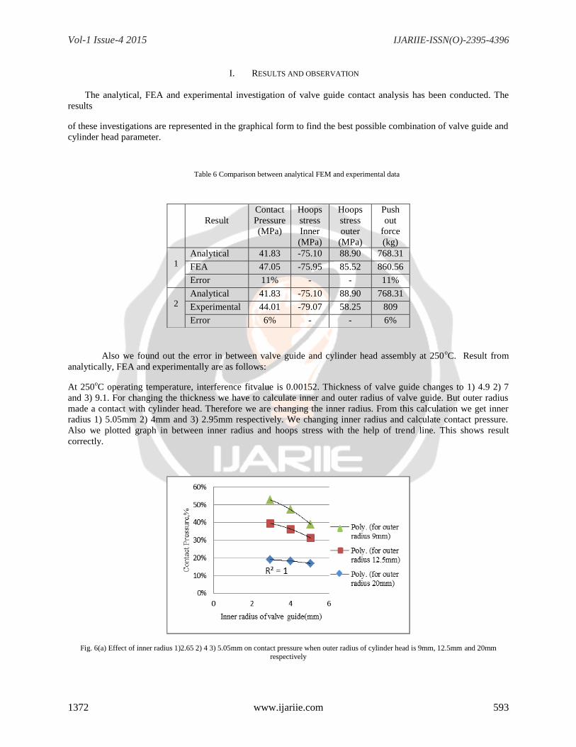
I. RESULTS AND OBSERVATION
The analytical, FEA and experimental investigation of valve guide contact analysis has been conducted. The
results
of these investigations are represented in the graphical form to find the best possible combination of valve guide and
cylinder head parameter.
Table 6 Comparison between analytical FEM and experimental data
Also we found out the error in between valve guide and cylinder head assembly at 250oC. Result from
analytically, FEA and experimentally are as follows:
At 250oC operating temperature, interference fitvalue is 0.00152. Thickness of valve guide changes to 1) 4.9 2) 7
and 3) 9.1. For changing the thickness we have to calculate inner and outer radius of valve guide. But outer radius
made a contact with cylinder head. Therefore we are changing the inner radius. From this calculation we get inner
radius 1) 5.05mm 2) 4mm and 3) 2.95mm respectively. We changing inner radius and calculate contact pressure.
Also we plotted graph in between inner radius and hoops stress with the help of trend line. This shows result
correctly.
Fig. 6(a) Effect of inner radius 1)2.65 2) 4 3) 5.05mm on contact pressure when outer radius of cylinder head is 9mm, 12.5mm and 20mm respectively
Result
Contact
Pressure
(MPa)
Hoops
stress
Inner
(MPa)
Hoops
stress
outer
(MPa)
Push
out
force
(kg)
1
Analytical 41.83 -75.10 88.90 768.31
FEA 47.05 -75.95 85.52 860.56
Error 11% - - 11%
2 Analytical 41.83 -75.10 88.90 768.31
Experimental 44.01 -79.07 58.25 809
Error 6% - - 6%

Vol-1 Issue-4 2015 IJARIIE-ISSN(O)-2395-4396
1372 www.ijariie.com 594
Fig. 6(b) Effect of inner radius 1)2.65 2) 4 3) 5.05mm on hoops stress when outer radius of cylinder head is 9mm, 12.5mm and 20mm respectively
At 250oC operating temperature, interference fitvalue is 0.00152. Stiffness of cylinder head (G/D ratio) changes to
1) 2.25 2) 3.125 and 3) 5. For changing the stiffness we have to calculate inner and outer radius of valve guide. But
inner radius made a contact with cylinder head. Therefore we are changing the outer radius. From this calculation
we get innerradius 1) 9mm 2) 12.5mm and 3) 20mm respectively.
Fig. 8(a) Effect of outer radius 1)9 2) 12.5 3) 20mm on contact pressure when inner radius of cylinder head is 5.05mm, 4mm and 2.95mm
respectively
Fig. 8(b) Effect of outer radius 1)9 2) 12.5 3) 20mm on hoops stress when inner radius of cylinder head is 5.05mm, 4mm and 2.95mm
respectively

Vol-1 Issue-4 2015 IJARIIE-ISSN(O)-2395-4396
1372 www.ijariie.com 595
At 250oC operating temperature, interference fitvalue is 0.003735 Thickness of valve guide changes to 1) 4.9 2) 7
and 3) 9.1. For changing the thickness we have to calculate inner and outer radius of valve guide. But outer radius
made an contact with cylinder head. Therefore we are changing the inner radius. From this calculation we get inner
radius 1) 5.05mm 2) 4mm and 3) 2.95mm respectively. We changing inner radius and calculate
Fig. 9(a) Effect of inner radius 1)2.65 2) 4 3) 5.05mm on contact pressure when outer radius of cylinder head is 9mm, 12.5mm and 20mm
respectively
Fig. 9(b) Effect of inner radius 1)2.65 2) 4 3) 5.05mm on hoops stress when outer radius of cylinder head is 9mm, 20mm and 12.5mm
respectively
At 250oC operating temperature, interference fitvalue is 0.00373. Stiffness of cylinder head (G/D ratio) changes to
1) 2.25 2) 3.125 and 3) 5. For changing the stiffness we have to calculate inner and outer radius of valve guide. But
inner radius made an contact with cylinder head. Therefore we are changing the outer radius. From this calculation
we get inner radius 1) 9mm 2) 12.5mm and 3) 20mm respectively. We changing inner radius and calculate contact
pressure. Also we plotting graph in between outer radius and hoops stress.

Vol-1 Issue-4 2015 IJARIIE-ISSN(O)-2395-4396
1372 www.ijariie.com 596
Fig. 10(a) Effect of outer radius 1)9 2) 12.5 3) 20mm on contact pressure when inner radius of cylinder head is 2.95mm, 5.05mm and 4mm
respectively
Fig. 10(b) Effect of outer radius 1)9 2) 12.5 3) 20mm on hoops stress when inner radius of cylinder head is 2.95mm, 5.05mm and 4mm
respectively
II. OBSERVATION
From the fig. 7, fig. 8, fig 9 and fig 10 we can say that, by changing the thickness of valve Guide and
cylinder head stiffness contact pressure is directly changing. For maximum contact pressure, maximum
push-out force required.
In Fig. 7 (a) for actual model, Inner radius is 4mm and outer radius is 12.5mm, we get contact pressure
36%. For better combination of inner radius of valve guide and cylinder head is more than 36%. And also it
is below allowable stress limit.
From the fig. 7, fig. 8, fig. 9 and fig. 10 we conclude that, minimum inner radiusof valve guide is 2.95mm
and maximum outer radius of cylinder head is 20mm is best combination.
III. CONCLUSION
Because of the complex geometry of the problem the analytical results are not perfectly match with FEA
and Experimental results. Contact pressure results are match within 11% and 6% error.

Vol-1 Issue-4 2015 IJARIIE-ISSN(O)-2395-4396
1372 www.ijariie.com 597
The effect of stress distribution at the interface between valve guide and cylinder head of diesel engine is
studied. By changing the thickness of valve guide and stiffness of material from this investigation, we got
combinations which overcome the valve guide loosening issue and that combination is below allowable
stress at operating temperature range.
The effect of various parameters on contact pressure is studied. It is observed that when stiffness of
cylinder head increases and thickness of valve guide decreases, the contact pressure on valve guide and
cylinder head increases by 17% for loose interference fit and 31% for tight interference fit. This is best case
for valve guide as it stays fit in cylinder head at operating temperature range.
IV. ACKNOWLEDGMENT
Thanks to Mr. Kedar Kanase, General Manager in Kirloskar Oil Engine Ltd. for giving the opportunity to work
on this challenging topic. And thanks to Prof. P.B. Joshi, HOD of MIT,Pune for support.
V. REFERENCES
[1] Y. Zhang, B. McClain, X.D. Fang,1998, “Design of interference fits via finite element method” International Journal of Mechanical Sciences vol. 42 pp. 1835-50
[2] Pauli Pedersen, 2006, “On Shrink Fit Analysis and Design” Springer vol. 37, pp 121–30
[3] Adnan O¨zel ,Emsettin Temiz, Murat Demir Aydin, Sadrien,2004, “Stress analysis of shrink-fitted joints for various fit forms via finite element method”International Journal of Materials and Design vol. 26, pp 281–89
[4] W. Kim, C. M. Lee and Y. K. Hwang, 2009,” A Study on the Shrink Fits and Internal Clearance Variation for Ball Bearing of Machine Tool using FEM” MultiConference of Engineers and Computer Scientists, Vol II ISBN: 978-988-17012-7-5
[5] Parson, Wilson EA., 1993,“A method for determining the surface contact stresses resulting from interference fits”. Journal of Engineering for Industry, Transactions of the ASME ; 208-18.
[6] T.Ozben, A.yardimeden, O.Cakir, 2007, “Stress analysis of shrink-fitted pin-pin hole connections via Finite element method” Journal
of achivments in material and manufacturing Engineering, Diyarbakir, Turkey Vol. 25, 1
[7] Bahattin Kanber, 2006 “Boundary Element Analysis of Interference Fits” Mechanical Engineering Science, 121, 230-240
[8] G. Karami, S.Ghazanfari Oskooei, 2010, “A thermoelastic analysis of shrink-fit type constructions by boundary element method”
International Journal of Mechanical Sciences vol 40 1801-1812
[9] N. Antoni, 2013, “Contact separation and failure analysis of a rotating thermo-elastoplasticshrink-fit assembly” Elsevier journal
Applied Mathematical Modelling vol 37, pp.2352–2363
[10] Susanta Choudhury ,2010, “Stress analysis of thick walled cylinder”, Batchler thesis,National Institute of Technology Rourkela,Odisha
[11] Craig C. Selvage, 1978, “Assembly of interference fits by impact and constant force methods” Master Thesis, Massachisetts institute of Technology, Cambridge, Massachusetts, United States
[12] Miraje, S. A. Patil, 2012 “Optimum thickness of three-layer shrink fittedCompound cylinder foruniform stressDistribution” International Journal