Stress Analysis of Coated Particle Fuel in the Deep-Burn ... · PDF fileStress analysis of...
15
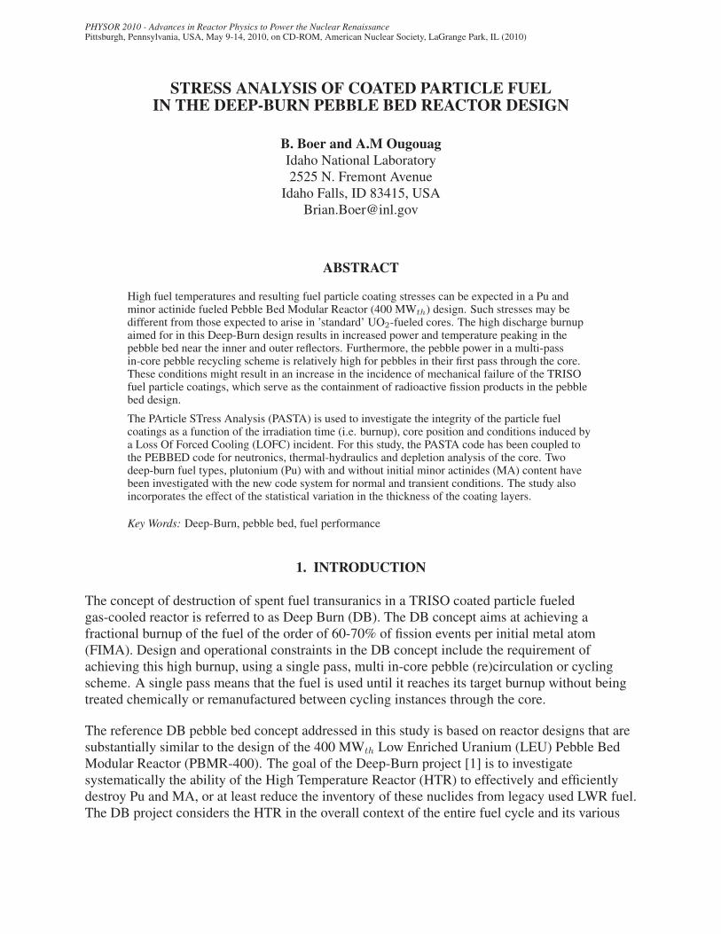
This is a preprint of a paper intended for publication in a journal or proceedings. Since changes may be made before publication, this preprint should not be cited or reproduced without permission of the author. This document was prepared as an account of work sponsored by an agency of the United States Government. Neither the United States Government nor any agency thereof, or any of their employees, makes any warranty, expressed or implied, or assumes any legal liability or responsibility for any third party’s use, or the results of such use, of any information, apparatus, product or process disclosed in this report, or represents that its use by such third party would not infringe privately owned rights. The views expressed in this paper are not necessarily those of the United States Government or the sponsoring agency. INL/CON-09-17162 PREPRINT Stress Analysis of Coated Particle Fuel in the Deep-Burn Pebble Bed Reactor Design PHYSOR 2010 B. Boer A. M. Ougouag May 2010
Transcript of Stress Analysis of Coated Particle Fuel in the Deep-Burn ... · PDF fileStress analysis of...
This is a preprint of a paper intended for publication in a journal or proceedings. Since changes may be made before publication, this preprint should not be cited or reproduced without permission of the author. This document was prepared as an account of work sponsored by an agency of the United States Government. Neither the United States Government nor any agency thereof, or any of their employees, makes any warranty, expressed or implied, or assumes any legal liability or responsibility for any third party’s use, or the results of such use, of any information, apparatus, product or process disclosed in this report, or represents that its use by such third party would not infringe privately owned rights. The views expressed in this paper are not necessarily those of the United States Government or the sponsoring agency.
INL/CON-09-17162PREPRINT
Stress Analysis of Coated Particle Fuel in the Deep-Burn Pebble Bed Reactor Design
PHYSOR 2010
B. Boer A. M. Ougouag
May 2010
PHYSOR 2010 - Advances in Reactor Physics to Power the Nuclear RenaissancePittsburgh, Pennsylvania, USA, May 9-14, 2010, on CD-ROM, American Nuclear Society, LaGrange Park, IL (2010)
STRESS ANALYSIS OF COATED PARTICLE FUELIN THE DEEP-BURN PEBBLE BED REACTOR DESIGN
B. Boer and A.M OugouagIdaho National Laboratory2525 N. Fremont Avenue
Idaho Falls, ID 83415, [email protected]
ABSTRACT
High fuel temperatures and resulting fuel particle coating stresses can be expected in a Pu andminor actinide fueled Pebble Bed Modular Reactor (400 MWth) design. Such stresses may bedifferent from those expected to arise in ’standard’ UO2-fueled cores. The high discharge burnupaimed for in this Deep-Burn design results in increased power and temperature peaking in thepebble bed near the inner and outer reflectors. Furthermore, the pebble power in a multi-passin-core pebble recycling scheme is relatively high for pebbles in their first pass through the core.These conditions might result in an increase in the incidence of mechanical failure of the TRISOfuel particle coatings, which serve as the containment of radioactive fission products in the pebblebed design.
The PArticle STress Analysis (PASTA) is used to investigate the integrity of the particle fuelcoatings as a function of the irradiation time (i.e. burnup), core position and conditions induced bya Loss Of Forced Cooling (LOFC) incident. For this study, the PASTA code has been coupled tothe PEBBED code for neutronics, thermal-hydraulics and depletion analysis of the core. Twodeep-burn fuel types, plutonium (Pu) with and without initial minor actinides (MA) content havebeen investigated with the new code system for normal and transient conditions. The study alsoincorporates the effect of the statistical variation in the thickness of the coating layers.
Key Words: Deep-Burn, pebble bed, fuel performance
1. INTRODUCTION
The concept of destruction of spent fuel transuranics in a TRISO coated particle fueledgas-cooled reactor is referred to as Deep Burn (DB). The DB concept aims at achieving afractional burnup of the fuel of the order of 60-70% of fission events per initial metal atom(FIMA). Design and operational constraints in the DB concept include the requirement ofachieving this high burnup, using a single pass, multi in-core pebble (re)circulation or cyclingscheme. A single pass means that the fuel is used until it reaches its target burnup without beingtreated chemically or remanufactured between cycling instances through the core.
The reference DB pebble bed concept addressed in this study is based on reactor designs that aresubstantially similar to the design of the 400 MWth Low Enriched Uranium (LEU) Pebble BedModular Reactor (PBMR-400). The goal of the Deep-Burn project [1] is to investigatesystematically the ability of the High Temperature Reactor (HTR) to effectively and efficientlydestroy Pu and MA, or at least reduce the inventory of these nuclides from legacy used LWR fuel.The DB project considers the HTR in the overall context of the entire fuel cycle and its various
Boer and Ougouag
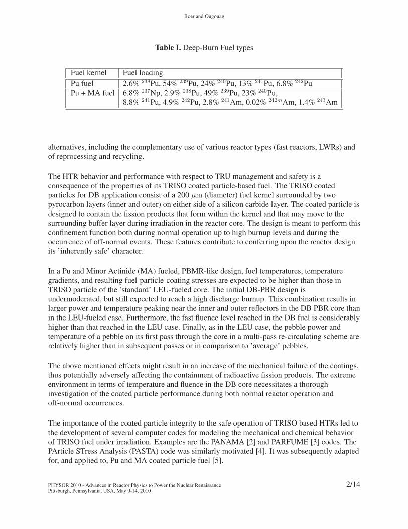
Table I. Deep-Burn Fuel types
Fuel kernel Fuel loading
Pu fuel 2.6% 238Pu, 54% 239Pu, 24% 240Pu, 13% 241Pu, 6.8% 242Pu
Pu + MA fuel 6.8% 237Np, 2.9% 238Pu, 49% 239Pu, 23% 240Pu,8.8% 241Pu, 4.9% 242Pu, 2.8% 241Am, 0.02% 242mAm, 1.4% 243Am
alternatives, including the complementary use of various reactor types (fast reactors, LWRs) andof reprocessing and recycling.
The HTR behavior and performance with respect to TRU management and safety is aconsequence of the properties of its TRISO coated particle-based fuel. The TRISO coatedparticles for DB application consist of a 200 μm (diameter) fuel kernel surrounded by twopyrocarbon layers (inner and outer) on either side of a silicon carbide layer. The coated particle isdesigned to contain the fission products that form within the kernel and that may move to thesurrounding buffer layer during irradiation in the reactor core. The design is meant to perform thisconfinement function both during normal operation up to high burnup levels and during theoccurrence of off-normal events. These features contribute to conferring upon the reactor designits ’inherently safe’ character.
In a Pu and Minor Actinide (MA) fueled, PBMR-like design, fuel temperatures, temperaturegradients, and resulting fuel-particle-coating stresses are expected to be higher than those inTRISO particle of the ’standard’ LEU-fueled core. The initial DB-PBR design isundermoderated, but still expected to reach a high discharge burnup. This combination results inlarger power and temperature peaking near the inner and outer reflectors in the DB PBR core thanin the LEU-fueled case. Furthermore, the fast fluence level reached in the DB fuel is considerablyhigher than that reached in the LEU case. Finally, as in the LEU case, the pebble power andtemperature of a pebble on its first pass through the core in a multi-pass re-circulating scheme arerelatively higher than in subsequent passes or in comparison to ’average’ pebbles.
The above mentioned effects might result in an increase of the mechanical failure of the coatings,thus potentially adversely affecting the containment of radioactive fission products. The extremeenvironment in terms of temperature and fluence in the DB core necessitates a thoroughinvestigation of the coated particle performance during both normal reactor operation andoff-normal occurrences.
The importance of the coated particle integrity to the safe operation of TRISO based HTRs led tothe development of several computer codes for modeling the mechanical and chemical behaviorof TRISO fuel under irradiation. Examples are the PANAMA [2] and PARFUME [3] codes. ThePArticle STress Analysis (PASTA) code was similarly motivated [4]. It was subsequently adaptedfor, and applied to, Pu and MA coated particle fuel [5].
PHYSOR 2010 - Advances in Reactor Physics to Power the Nuclear RenaissancePittsburgh, Pennsylvania, USA, May 9-14, 2010
2/14
Stress analysis of coated particle fuel in the deep-burn pebble bed reactor design
More recently the PASTA code was further improved and coupled to the PEBBED code [6] forneutronic, thermal-hydraulic and depletion analysis of the core. This new coupled code systemallows for the determination of the coated particle performance as a function of the local and timedependent core parameters (temperature, fluence, burnup, irradiation time and fission productconcentration). This allows for determination of the stress effects caused by the power andtemperature peaking that are typically found in a DB core design. Furthermore, stresses can beevaluated for slow transients such as a Loss Of Forced Cooling (LOFC) incident.
Two deep-burn fuel types (Pu alone and Pu+MA) (see Table I) have been investigated with thenew code system for normal and transient conditions, including the effect of the statisticalvariation of the thickness of the coating layers. The outline of the rest of this paper is as follows.Section 2 presents the newly developed PEBBED-PASTA code system. Section 3.1 gives a shortdescription of the DB core design and its nominal operating conditions. Results on the referencefuel particle performance at nominal conditions are given in Sec. 3.2. The following sections (3.3and 3.4) show the stress levels dependence on the radial position within the core and the effect ofthe variation in the size of the coatings. Also discussed is the influence of the amount of freeoxygen released per fission event. In Sec. 3.5 the performance during the LOFC transientconditions is presented. Section 4 concludes on the overall performance of the two types of fuelinvestigated for the different cases.
2. CODE SYSTEM FOR ANALYSIS OF COATED PARTICLE STRESSES
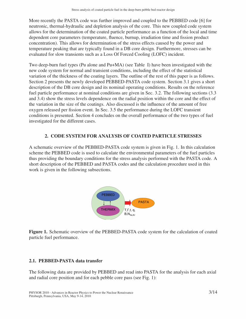
A schematic overview of the PEBBED-PASTA code system is given in Fig. 1. In this calculationscheme the PEBBED code is used to calculate the environmental parameters of the fuel particlesthus providing the boundary conditions for the stress analysis performed with the PASTA code. Ashort description of the PEBBED and PASTA codes and the calculation procedure used in thiswork is given in the following subsections.
PASTA
PEBBED
THERMIX T,Γ,t, q, B,NXe,Kr
Figure 1. Schematic overview of the PEBBED-PASTA code system for the calculation of coatedparticle fuel performance.
2.1. PEBBED-PASTA data transfer
The following data are provided by PEBBED and read into PASTA for the analysis for each axialand radial core position and for each pebble core pass (see Fig. 1):
PHYSOR 2010 - Advances in Reactor Physics to Power the Nuclear RenaissancePittsburgh, Pennsylvania, USA, May 9-14, 2010
3/14
Boer and Ougouag
1. T : The temperature of the fuel. PEBBED provides the average fuel, average pebble centerand pass-dependent pebble-center fuel temperature histories, which can be used in separatestress analysis evaluations.
2. Γ : The fast neutron fluence (E > 0.1 MeV), which is calculated with PEBBED from a 28group energy group structure used for the full core calculation.
3. q′′′: The power density history can be read for use in reconstructing the fuel kerneltemperature; the PASTA code can use this information to perform sampling over thetemperature profile in the fuel zone of the pebble.
4. B: The burnup level of the fuel.
5. t: The residence time, which is used in conjunction with Eq. (5) for the calculation of freeoxygen production.
6. NXe,Kr: The production rate of the stable gaseous fission products of Xe and Kr (83Kr, 84Kr,85Kr, 86Kr, 131Xe,132Xe, 134Xe, 136Xe) within the kernel.
2.2. PEBBED
The PEBBED code [6] is a tool for analyzing the asymptotic fuel cycle in re-circulating pebblebed reactors. Equations for neutron flux and nuclide distribution in a pebble bed core are solvedself-consistently via an iterative scheme. The neutronic solver can use a standard finite differencetechnique or a nodal diffusion method. The burnup solver uses a semi-analytical method thatguarantees convergence and accuracy. Homogenized nuclear data are provided using theSCALE-6 [7] code system, while temperature feedback and thermal-hydraulic analysis isperformed with THERMIX(KONVEK) [8].
2.3. PASTA
The PASTA code [4, 5] describes the mechanical behavior of TRISO particles during irradiationand aims at calculating the coating stresses and the corresponding failure probabilities. TheTRISO particles have a Pu/MA Ox fuel kernel of 200 μm in diameter at their very center.Adjacent to the kernel is a 90 μm thick porous carbon buffer, which is coated with an innerpyrolytic carbon (IPyC) layer (35 μm), a silicon carbide (SiC) layer (45 μm), and an outerpyrolytic carbon (OPyC) layer (35 μm). These coatings provide the primary containment of thefission products that are generated within the fuel kernel.
PASTA embodies a one-dimensional analytical and multi-layer model that takes into account thevisco-elastic behavior of the coating layers and the surrounding graphite during irradiation. Themain source of stress in all layers is due to the pressure build-up from the gaseous fission productsin the buffer layer resulting in a radial stress on the IPyC. Moreover, the Pyrocarbon (IPyC andOPyC) layers exhibit radiation-induced dimensional changes and creep (in the radial andtangential directions). Finally, the model allows thermal expansion of all layers. PASTA solvesthe general stress strain equations, which include the aforementioned effects, and are as follows
PHYSOR 2010 - Advances in Reactor Physics to Power the Nuclear RenaissancePittsburgh, Pennsylvania, USA, May 9-14, 2010
4/14
Stress analysis of coated particle fuel in the deep-burn pebble bed reactor design
for the radial and tangential direction of a spherical layer [4]:
∂εr
∂t=
1
E
[∂σr
∂t− 2μ
∂σt
∂t
]+ c [σr − 2νσt] + αrT + Sr (1)
∂εt
∂t=
1
E
[(1 − μ)
∂σt
∂t− μ
∂σr
∂t
]+ c [(1 − ν)σt − νσr] + αtT + St (2)
The mechanical failure probability (Ψ) of the coated particle is determined from the magnitude ofthe (tensile) stress in the SiC layer, which is the main load-bearer, according to the followingWeibull distribution:
Ψ = 1 − exp
(− ln (2)
(σt
σmed
)m)(3)
in which σt is the tangential (tensile) stress in the SiC layer, σmed the median strength of the of theSiC and m is the Weibull modulus of the SiC strength. These latter two parameters are taken to beσmed = 340 MPa and m = 5, [9]. The internal pressure in the coated particle results from gaseousfission products (Xe and Kr) that accumulate in the kernel and diffuse to the buffer layer duringirradiation. The buildup of gaseous fission products can be calculated both analytically andnumerically by solving the time-dependent fission product diffusion equation:
∂C
∂t=
D(T )
r2
[∂
∂t
(r2∂C
∂r
)]+ β (4)
in which β is the production rate of fission products and D(T ) [s−1m2] is the temperaturedependent diffusion coefficient, which can be calculated according to (assuming Xe and Kr as thefission products):
D′(T ) = 5.10−3e(− QRT
) (5)
with D′ = Dr2 , Q = 155.4 103 J/mol and R = 8.314 J/mol/K. In the PASTA code both a numerical
method using a finite difference scheme and a fast analytical method [5] for the calculation of thefractional release of fission products from the kernel to the buffer can be used. The source term βis largely determined by production of the gaseous fission products Xe and Kr. Besides directformation of gaseous fission products, formation of CO gas is possible by a reaction of the freeoxygen present in the fuel kernel with the carbon in the buffer layer. The formation of this gas istaken into account by the following empirical formula for oxygen release per fission event (forUO2 fuel):
O/f = 8.32 · 10−11t2irr · e(−Z/RT ) (6)
It is noted that the expected CO/CO2 production from DB fuels is higher than for UO2 fuel [10].The above equation is used since experimental data for CO production from DB particle fuels islacking. A sensitivity study is performed assuming more conservative O
ffractions of 0.4 and 0.6
in the following analysis besides Eq. (6).
The resulting pressure (from both fission products and CO accumulation) on the IPyC layer iscalculated as a function of the kernel temperature and the buffer volume with the Redlich Kwongequation of state:
RT =
(p +
a
T12 Vm (Vm + b)
)(Vm − b) (7)
The ideal gas law is not used here, because it under predicts the pressure significantly.
PHYSOR 2010 - Advances in Reactor Physics to Power the Nuclear RenaissancePittsburgh, Pennsylvania, USA, May 9-14, 2010
5/14
Boer and Ougouag
The PyC coating layers exhibit a dimensional change under irradiation in a fast neutron flux. InReference [12] the dimensional change as a function of the fast neutron fluence (E >0.18 MeV) isfitted for several temperatures and Bacon Anisotropy Factors (BAFs). Pyrocarbon and graphitematerials creep under irradiation, partly reducing the stress. For the pyrocarbon layers a value of2.0·10−29 (MPa·m−2)−1 for the creep coefficient was adopted from the literature [11]. Thermalexpansion of the PyC layers is incorporated in the model and the thermal expansion coefficients,which depend on the BAF, are taken from Reference [12]. Note that for the isotropic case BAF =1, and αr= αt= 50/9= 5.6·10−6 [K−1]. The thermal expansion coefficient of SiC depends on thetemperature [9] and has an average value of αSiC = 4.4·10−6 [K−1] in the range298 K < T < 1273 K. Since the thermal expansion coefficient of the PyC layers is larger thanthe SiC layer for the entire temperature range, a resulting tensile stress in the SiC layer can beexpected for a uniform temperature increase of the coatings.
3. RESULTS
This section presents the results of the fuel performance analysis for the reference particle undernominal conditions first (Sec. 3.1 and 3.2). The following sections illustrate the impact on theperformance of the variation in radial core position, CO production, and coating thickness(Sec. 3.3 and 3.4). Finally, LOFC transient conditions are taken into account (Sec. 3.5).
3.1. Deep-Burn pebble bed reactor core and fuel design
The PBMR-400 core design is shown in Fig. 2(a). The 400 MWth pebble bed core has an innerand outer radius of 1 m and 1.85 m, respectively, and is 11 m in height. Table II gives an overviewof the fuel and mechanical properties of the coatings used in the PEBBED and PASTA models.
Table II. Material properties of the TRISO coated particles
I/OPyC Material property Value
Young’s modulus of elasticity [MPa] 3.96·104
Poisson’s ratio [-] 0.33
Poisson’s ratio of creep [-] 0.4
Creep coefficient [10−25(MPa.m−2)−1] 2.0·10−4
Dimensional change rate [10−25(MPa.m−2)−1] Ref. [12]
Thermal expansion coefficient [K−1] Ref. [12]
BAF 1.0
SiC Material property Value
Young’s modulus of elasticity [MPa] 4.0·105
Poisson’s ratio [-] 0.13
Thermal expansion coefficient [K−1] Ref. [9]
PHYSOR 2010 - Advances in Reactor Physics to Power the Nuclear RenaissancePittsburgh, Pennsylvania, USA, May 9-14, 2010
6/14
Stress analysis of coated particle fuel in the deep-burn pebble bed reactor design
(a) PBMR core design
Power density profile [MW/m3]
R [cm]
Z [c
m]
16
14
12 10
10
14
9
8 87
5 54
3 3
2
11
36
8
100 150 185
0
100
200
300
400
500
600
700
800
900
1000
1100
(b) Power profile
Fuel temperature [K]
R [cm]
Z [c
m]
1250
1225
1200
1175
1175
1175
1150
10751000
975850
100 150 185
0
100
200
300
400
500
600
700
800
900
1000
1100
(c) Tfuel profile
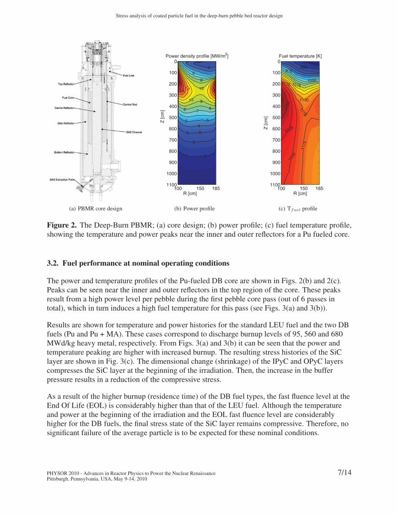
Figure 2. The Deep-Burn PBMR; (a) core design; (b) power profile; (c) fuel temperature profile,showing the temperature and power peaks near the inner and outer reflectors for a Pu fueled core.
3.2. Fuel performance at nominal operating conditions
The power and temperature profiles of the Pu-fueled DB core are shown in Figs. 2(b) and 2(c).Peaks can be seen near the inner and outer reflectors in the top region of the core. These peaksresult from a high power level per pebble during the first pebble core pass (out of 6 passes intotal), which in turn induces a high fuel temperature for this pass (see Figs. 3(a) and 3(b)).
Results are shown for temperature and power histories for the standard LEU fuel and the two DBfuels (Pu and Pu + MA). These cases correspond to discharge burnup levels of 95, 560 and 680MWd/kg heavy metal, respectively. From Figs. 3(a) and 3(b) it can be seen that the power andtemperature peaking are higher with increased burnup. The resulting stress histories of the SiClayer are shown in Fig. 3(c). The dimensional change (shrinkage) of the IPyC and OPyC layerscompresses the SiC layer at the beginning of the irradiation. Then, the increase in the bufferpressure results in a reduction of the compressive stress.
As a result of the higher burnup (residence time) of the DB fuel types, the fast fluence level at theEnd Of Life (EOL) is considerably higher than that of the LEU fuel. Although the temperatureand power at the beginning of the irradiation and the EOL fast fluence level are considerablyhigher for the DB fuels, the final stress state of the SiC layer remains compressive. Therefore, nosignificant failure of the average particle is to be expected for these nominal conditions.
PHYSOR 2010 - Advances in Reactor Physics to Power the Nuclear RenaissancePittsburgh, Pennsylvania, USA, May 9-14, 2010
7/14

Boer and Ougouag
0 1 2 3 4 5 60
2
4
6
8
10
Pebble pass
Peb
ble
pow
er [k
W]
Pu fuel
Pu + MA fuel
U fuel
(a) Pebble power
0 1 2 3 4 5 6800
900
1000
1100
1200
1300
1400
1500
1600
Tem
pera
ture
[K]
Pebble pass
Pu fuel
Pu + MA fuel
U fuel
(b) Fuel temperature (c) SiC tangential stress
Figure 3. Pebble power (a); fuel temperature (b); and SiC coating stress (c) in Deep-Burn (Puand Pu+MA fuel) and UO2 fueled PBMR cores. For all cases the pebbles make 6 (re)circulationsthrough the core.
3.3. SiC coating stress as a function of the pebble location
A fuel performance analysis is performed that takes into account the fuel temperature variation inthe radial direction of the core. Figs. 4(a) and 4(b) show 2-D core distribution maps of themaximum SiC stress in the particles for the two fuel types. The results show that the pebbles nearthe radial edges of the pebble bed, which experience high temperatures, contain particles thathave a significantly higher SiC stress when compared to the stress in the average particle (seeSec. 3.2).
(a) Pu fuel (b) Pu + MA fuel
Figure 4. SiC coating stress, for a pebble that has been (re)introduced in the core for 6 times,as function of the position the DB core at nominal conditions for Pu (a); and Pu+MA (b) fueleddesigns.
PHYSOR 2010 - Advances in Reactor Physics to Power the Nuclear RenaissancePittsburgh, Pennsylvania, USA, May 9-14, 2010
8/14
Stress analysis of coated particle fuel in the deep-burn pebble bed reactor design
(a) Of
: Eq. (6) (b) Of
: 0.4
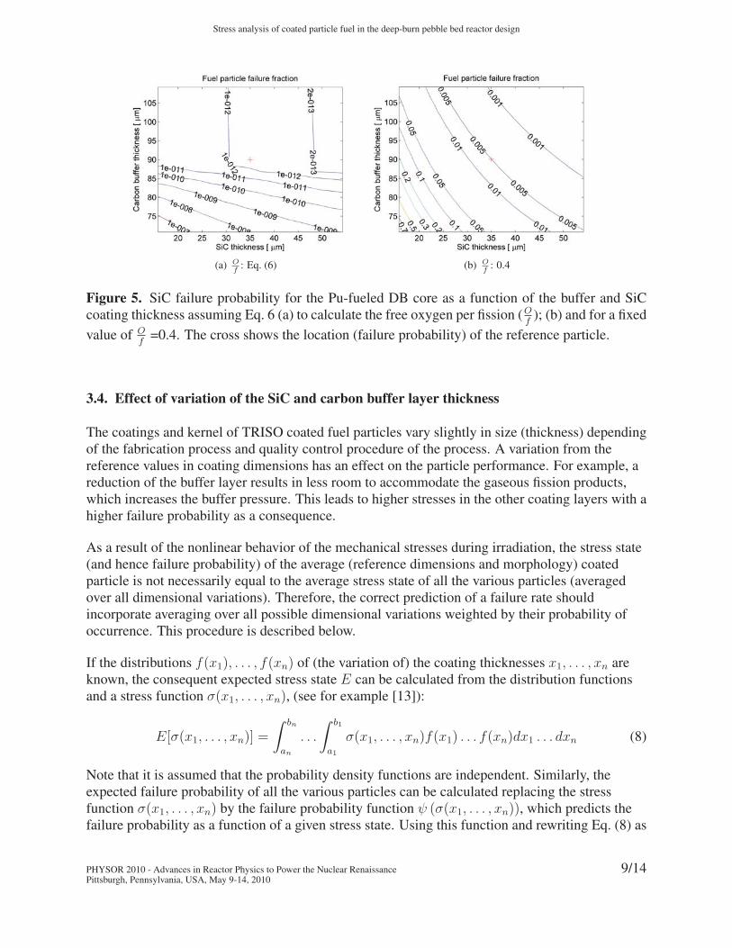
Figure 5. SiC failure probability for the Pu-fueled DB core as a function of the buffer and SiCcoating thickness assuming Eq. 6 (a) to calculate the free oxygen per fission (O
f); (b) and for a fixed
value of Of
=0.4. The cross shows the location (failure probability) of the reference particle.
3.4. Effect of variation of the SiC and carbon buffer layer thickness
The coatings and kernel of TRISO coated fuel particles vary slightly in size (thickness) dependingof the fabrication process and quality control procedure of the process. A variation from thereference values in coating dimensions has an effect on the particle performance. For example, areduction of the buffer layer results in less room to accommodate the gaseous fission products,which increases the buffer pressure. This leads to higher stresses in the other coating layers with ahigher failure probability as a consequence.
As a result of the nonlinear behavior of the mechanical stresses during irradiation, the stress state(and hence failure probability) of the average (reference dimensions and morphology) coatedparticle is not necessarily equal to the average stress state of all the various particles (averagedover all dimensional variations). Therefore, the correct prediction of a failure rate shouldincorporate averaging over all possible dimensional variations weighted by their probability ofoccurrence. This procedure is described below.
If the distributions f(x1), . . . , f(xn) of (the variation of) the coating thicknesses x1, . . . , xn areknown, the consequent expected stress state E can be calculated from the distribution functionsand a stress function σ(x1, . . . , xn), (see for example [13]):
E[σ(x1, . . . , xn)] =
∫ bn
an
. . .
∫ b1
a1
σ(x1, . . . , xn)f(x1) . . . f(xn)dx1 . . . dxn (8)
Note that it is assumed that the probability density functions are independent. Similarly, theexpected failure probability of all the various particles can be calculated replacing the stressfunction σ(x1, . . . , xn) by the failure probability function ψ (σ(x1, . . . , xn)), which predicts thefailure probability as a function of a given stress state. Using this function and rewriting Eq. (8) as
PHYSOR 2010 - Advances in Reactor Physics to Power the Nuclear RenaissancePittsburgh, Pennsylvania, USA, May 9-14, 2010
9/14
Boer and Ougouag
a function of discrete points results in:
E[ψ (σ(x1, . . . , xn))] =∑xn
. . .∑x1
ψ (σ(x1, . . . , xn)) p(x1) . . . p(xn) (9)
The above integral is implemented in the PASTA code. The failure probability(ψ (σ(x1, . . . , xn))) for given particle dimensions is calculated from the coating stresses. Thisprobability is weighted with the probability of the particle having these dimensions(p(x1) . . . p(xn)). The expected failure fraction of all the particles combined(E[ψ (σ(x1, . . . , xn))]), is obtained by evaluation and summation of the failure probabilities ofseveral different cases in which the coating layer thicknesses are varied.
A PASTA calculation has been performed assuming Weibull distributions [13] for the SiC andcarbon buffer layer thickness (μSiC=45μm, σSiC= 5μm and μCbuf
=90μm, σCbuf= 5μm). The
failure probability of the SiC layer as a function of the SiC and carbon buffer thickness has beencalculated assuming either Eq. (6) or a more conservative (fixed) value of O
f= 0.4 for the free
oxygen production (see Figs. 5(a) and 5(b)).
It can be seen that for (Of
: Eq 6) the particle failure probability remains low for all coating
dimensions (Fig. 5(a)) with an overall failure probability (see Eq. 8) of 3.8·10−11. However, if amore conservative value of O
f= 0.4 is assumed high failure probabilities can be expected
(Fig. 5(b)) with an overall value of 8.0·10−3.
(a) DLOFC maximum fuel temperature history
100 150 185
0
100
200
300
400
500
600
700
800
900
1000
1100
Fuel temperature [K]
R [cm]
Z [c
m]
+←2043 K
1900
1900
1600
1500
1300
1300
1100
11001000
900
1600 1400
1200
1700
(b) DLOFC fuel temperatureprofile
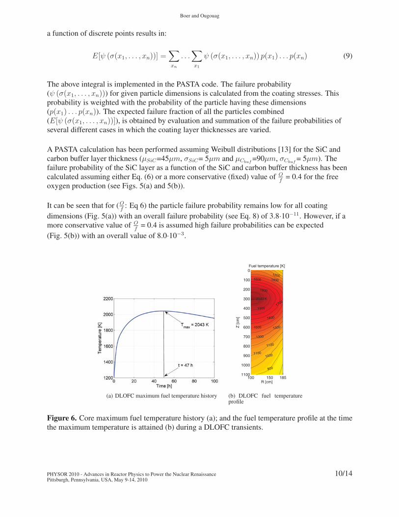
Figure 6. Core maximum fuel temperature history (a); and the fuel temperature profile at the timethe maximum temperature is attained (b) during a DLOFC transients.
PHYSOR 2010 - Advances in Reactor Physics to Power the Nuclear RenaissancePittsburgh, Pennsylvania, USA, May 9-14, 2010
10/14
Stress analysis of coated particle fuel in the deep-burn pebble bed reactor design
3.5. Fuel performance at Loss Of Forced Cooling conditions
During a LOFC incident the center part of the core can be expected to reach considerably highertemperatures than the nominal operation values. As can be seen from Eq. 7 the pressure in thebuffer layer is directly dependent on the temperature. It is also indirectly dependent on thetemperature through the diffusion of fission products (Eq. 5) and the CO production rate (Eq. 6).Furthermore, the stress in the SiC layer is a function of the thermal expansion of the SiC layeritself and the PyC layers.
A LOFC transient calculation has been performed using a standalone thermal-hydraulicscalculation within PEBBED. Fig. 6(a) shows the core maximum fuel temperature history of aLOFC transient and Fig. 6(b) shows the core temperature profile at the time when the maximumtemperature (t = 47 h) is reached.
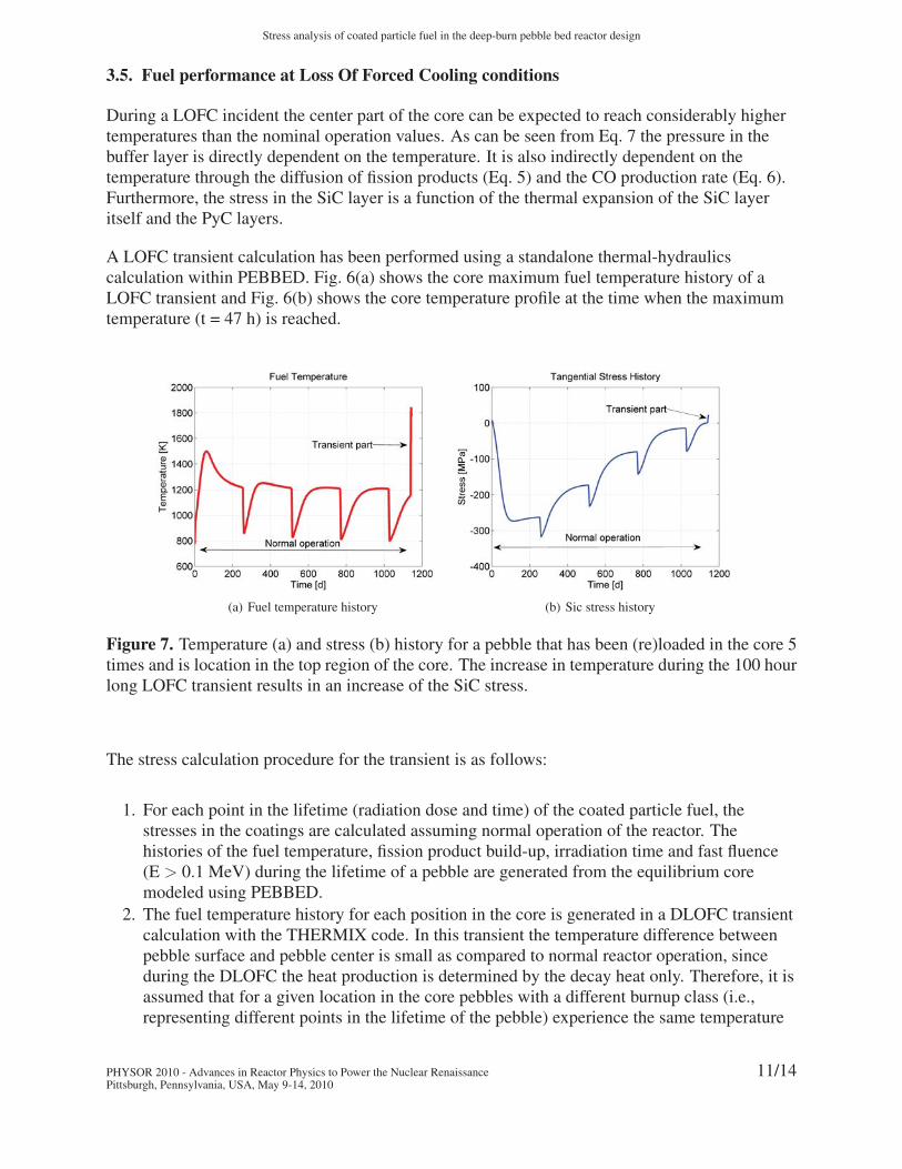
(a) Fuel temperature history (b) Sic stress history
Figure 7. Temperature (a) and stress (b) history for a pebble that has been (re)loaded in the core 5times and is location in the top region of the core. The increase in temperature during the 100 hourlong LOFC transient results in an increase of the SiC stress.
The stress calculation procedure for the transient is as follows:
1. For each point in the lifetime (radiation dose and time) of the coated particle fuel, thestresses in the coatings are calculated assuming normal operation of the reactor. Thehistories of the fuel temperature, fission product build-up, irradiation time and fast fluence(E > 0.1 MeV) during the lifetime of a pebble are generated from the equilibrium coremodeled using PEBBED.
2. The fuel temperature history for each position in the core is generated in a DLOFC transientcalculation with the THERMIX code. In this transient the temperature difference betweenpebble surface and pebble center is small as compared to normal reactor operation, sinceduring the DLOFC the heat production is determined by the decay heat only. Therefore, it isassumed that for a given location in the core pebbles with a different burnup class (i.e.,representing different points in the lifetime of the pebble) experience the same temperature
PHYSOR 2010 - Advances in Reactor Physics to Power the Nuclear RenaissancePittsburgh, Pennsylvania, USA, May 9-14, 2010
11/14
Boer and Ougouag
history during the transient. This is a plausible assumption since the small differencebetween pebble center and pebble surface temperature implies that the temperature in allpebbles will be similar.
3. The temperature history of a pebble now consists of two parts. The first part representsnormal reactor operation, in which the pebble reaches a given point in life at which thetransient occurs. At this point the pebble has passed several times through the core and hasreached a certain core position. The second part of the pebble temperature history isdetermined by the temperature that this core location implies per the discussion above. Thetemperature history during normal operation and the subsequent transient is shown inFig. 7(a).
4. For each position in the core the 6 (1 to 6 pebble (re-)circulations completed) possibletemperature histories are used to calculate the corresponding histories for the pressurebuildup in the buffer layer.
5. The stress state of the coatings is calculated during the entire lifetime of the pebbles (normaloperation and subsequent transient). This is shown in Fig. 7(b).
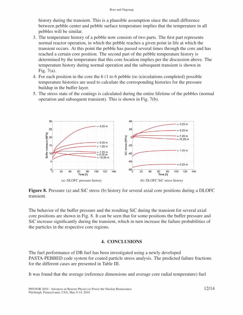
(a) DLOFC pressure history (b) DLOFC SiC stress history
Figure 8. Pressure (a) and SiC stress (b) history for several axial core positions during a DLOFCtransient.
The behavior of the buffer pressure and the resulting SiC during the transient for several axialcore positions are shown in Fig. 8. It can be seen that for some positions the buffer pressure andSiC increase significantly during the transient, which in turn increase the failure probabilities ofthe particles in the respective core regions.
4. CONCLUSIONS
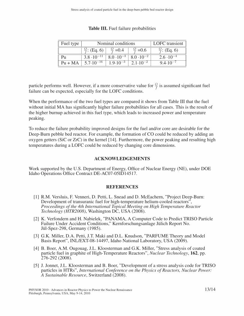
The fuel performance of DB fuel has been investigated using a newly developedPASTA-PEBBED code system for coated particle stress analysis. The predicted failure fractionsfor the different cases are presented in Table III.
It was found that the average (reference dimensions and average core radial temperature) fuel
PHYSOR 2010 - Advances in Reactor Physics to Power the Nuclear RenaissancePittsburgh, Pennsylvania, USA, May 9-14, 2010
12/14
Stress analysis of coated particle fuel in the deep-burn pebble bed reactor design
Table III. Fuel failure probabilities
Fuel type Nominal conditions LOFC transientOf
: (Eq. 6) Of
=0.4 Of
=0.6 Of
: (Eq. 6)
Pu 3.8 ·10−11 8.0 ·10−3 8.0 ·10−2 2.6 ·10−4
Pu + MA 5.7·10−16 1.9·10−3 2.1·10−2 9.4·10−7
particle performs well. However, if a more conservative value for Of
is assumed significant fuelfailure can be expected, especially for the LOFC conditions.
When the performance of the two fuel types are compared it shows from Table III that the fuelwithout initial MA has significantly higher failure probabilities for all cases. This is the result ofthe higher burnup achieved in this fuel type, which leads to increased power and temperaturepeaking.
To reduce the failure probability improved designs for the fuel and/or core are desirable for theDeep-Burn pebble bed reactor. For example, the formation of CO could be reduced by adding anoxygen getters (SiC or ZrC) in the kernel [14]. Furthermore, the power peaking and resulting hightemperatures during a LOFC could be reduced by changing core dimensions.
ACKNOWLEDGEMENTS
Work supported by the U.S. Department of Energy, Office of Nuclear Energy (NE), under DOEIdaho Operations Office Contract DE-AC07-05ID14517.
REFERENCES
[1] R.M. Versluis, F. Venneri, D. Petti, L. Snead and D. McEachern, ”Project Deep-Burn:Development of transuranic fuel for high-temperature helium-cooled reactors”,Proceedings of the 4th International Topical Meeting on High Temperature ReactorTechnology (HTR2008), Washington DC, USA (2008).
[2] K. Verfondern and H. Nabielek, ”PANAMA, A Computer Code to Predict TRISO ParticleFailure Under Accident Conditions,” Kernforschungsanlage Julich Report No.Jul-Spez-298, Germany (1985).
[3] G.K. Miller, D.A. Petti, J.T. Maki and D.L. Knudson, ”PARFUME Theory and ModelBasis Report”, INL/EXT-08-14497, Idaho National Laboratory, USA (2009).
[4] B. Boer, A.M. Ougouag, J.L. Kloosterman and G.K. Miller, ”Stress analysis of coatedparticle fuel in graphite of High-Temperature Reactors”, Nuclear Technology, 162, pp.276-292 (2008).
[5] J. Jonnet, J.L. Kloosterman and B. Boer, ”Development of a stress analysis code for TRISOparticles in HTRs”, International Conference on the Physics of Reactors, Nuclear Power:A Sustainable Resource, Switzerland (2008).
PHYSOR 2010 - Advances in Reactor Physics to Power the Nuclear RenaissancePittsburgh, Pennsylvania, USA, May 9-14, 2010
13/14
Boer and Ougouag
[6] W.K. Terry, H.D. Gougar and A.M. Ougouag, ”Direct Deterministic Method for NeutronicsAnalysis and Computation of Asymptotic Burnup Distribution in a RecirculatingPebble-Bed Reactor”, Annals of Nuclear Energy, 29, pp. 13451364 (2002).
[7] SCALE-6, A Modular Code System for Performing Standardized Computer Analysis forLicensing Evaluations, RNL/TM2005/39, Version 6.0, Vols I-III, ORNL, (2009).
[8] E. Teuchert et al, ”V.S.O.P. Computer Code System for Reactor Physics and Fuel CycleSimulation”, Forschungszentrum Julich GmbH Jul-2897, (1994).
[9] L.L. Snead, T. Nozawa, Y. Katoh, T-S. Byun, S. Kondo and D. Petti, ”Handbook of SiCproperties for fuel performance modeling”, Journal of Nuclear Materials, 371, pp.329-377(2007).
[10] G.W. Horsley, G.J. Weldrick, J.A. Turnbull and R. Shipp, ”Influence of IrradiationTemperature, Burnup, and Fuel Composition on Gas Pressure (Xe, Kr, CO, CO2) in CoatedParticle Fuels”, Journal of the American Ceramic Society, 59, (1976).
[11] Development for improved models and designs for coated particle gas reactor fuels,INEEL/EXT-05-02615, INEEL (2004).
[12] F. Ho, ”Material Models of Pyrocarbon and Pyrolytic Silicon Carbide”, CEGA-002820,San Diego, USA (1993).
[13] J.L. Devore, Probability & Statistics for Engineering and the Sciences, Brooks/Cole,(1982).
[14] T.M. Besmann, ”Thermochemical assessment of oxygen gettering by SiC or ZrC inPuO2−x TRISO fuel”, Journal of Nuclear Materials, 397, pp.69-73 (2010).
PHYSOR 2010 - Advances in Reactor Physics to Power the Nuclear RenaissancePittsburgh, Pennsylvania, USA, May 9-14, 2010
14/14