Strengthening of web opening in non-compact steel girders
14
IOSR Journal of Mechanical and Civil Engineering (IOSR-JMCE) e-ISSN: 2278-1684,p-ISSN: 2320-334X, Volume 12, Issue 5 Ver. II (Sep. - Oct. 2015), PP 34-47 www.iosrjournals.org DOI: 10.9790/1684-12523447 www.iosrjournals.org 34 | Page Strengthening of web opening in non-compact steel girders Fattouh M. F. Shaker 1 and Mahmoud Shahat 2 1 Assistant Professor, Civil Eng. Department, Faculty of Eng. Mataria, Helwan University, Cairo. 2 Graduate student, Civil Eng. Department, Faculty of Eng. Mataria, Helwan University, Cairo. Abstract: The use of web openings to pass the utilities of structures through steel beams can help in minimizing buildings height and hence decreasing operational and maintenance costs. However, web openings can significantly reduce the shear and bending strength capacity of the steel beams. The last researches focused on the study of perforated beams with compact steel webs to exclude the effect of local buckling. Therefore, the objective of this paper is to study the effect of web openings on the capacity of beams having non-compact sections in order to determine the critical positions of web openings. Thus, supposing the suitable technique for web strengthening according to shape, size and location of the opening with respect to beam length. The study is focused on the non-compact and slender web beams due to its economical and common uses. The study also investigated the efficiency of different types of stiffeners welded at the opening regions in order to increase the beams ultimate load carrying capacity. The obtained results showed that the longitudinal stiffeners is the best strengthening system. The analytical investigation utilizes nonlinear finite element modeling techniques using ANSYS program, considering both geometric and material nonlinearities. The results of the finite element models were verified with the results of experimental tests found in literature. Keywords: Non-Linear Analysis, Steel Structures, Web Openings, Perforated Steel Girder, Vierendeel Mechanism, Web Reinforcement, Non-compact Web and Finite Element Method. I. Introduction Passing of utilities and services such as ventilation ducts, air condition ducts, electrical and data communication systems, fire protection systems, heating and cooling systems and instrumentation cables may be needed to increasing the floor height. This leads to additional cost, beside it is unacceptable choice from the architectural view, where there is a strict requirement on the story height of many buildings especially in modern multistory buildings. Therefore, openings should be provided in the web of steel girders to permit passing the utilities within the constructional depth of the floor which result minimizing the floor height to give a good architectural emphasis. However, the existence of web openings may have a significant passive effect, where the beam may be weakened in the vicinity of the opening due to the reduction in the beam strength which will occur. The method of using the shear-moment interaction curves was widely used in the past, but the methodology is now enhanced by a comprehensive finite element study. Many researchers have surveyed the behavior, strength, and establish a design methodology for designing beams without or with reinforced web openings. Recently, researchers tend to study the behavior and determine the load capacity for different types of perforated compact steel beams under distributed and concentrated loads. Congdon and Redwood [1] carried out tests on a beam with a compact web having a single reinforced rectangular opening to estimate the strength of beams with reinforced rectangular holes assuming perfectly plastic behavior. Moreover, they estimated the required area of reinforcement in order to achieve the maximum shear carrying capacity of the section. Cooper and Snell [2] conducted an experimental investigation on sixteen simply supported beams of A36 steel W12x45 shapes. They carried out the tests by subjecting the beams to a single concentrated load at mid span under various moment-to-shear ratio to obtain the elastic stresses in the vicinity of web openings. They found that the basis of vierendeel method of analysis to calculate the normal stresses at the perforated section was in good agreement with the measured experimental normal stresses. The horizontal shear stresses calculated by the vierendeel method did not match well with the measured shear stresses. Lupien and Redwood [3] conducted an experimental investigation on six simply supported beams with mid depth rectangular web openings. The openings were reinforced horizontally from one side of the beam web which was considered as slender. They tested the beams under various moment-to-shear ratios to study the efficiency and effect of one sided reinforcement for the opening to gain from its economy in welding and handling. They found that there are some situations where the reinforcement placed on one side of the web opening could be used. Also, they found that the necessary anchorage length of the reinforcement will normally be greater than for the same area symmetrically placed. Darwin [4] is prepared a guide for the design of steel and composite beams with web openings due to the recommendations of the committee of research of the American Institute of Steel Construction. This is part of a series of publications on special topics related to fabricated-structural steel beams. Its purpose is to serve as a supplemental reference to the AISC manual of Steel Construction to assist practicing engineers engaged in building design [5] . This design guide presents a unified approach to the design of
-
Upload
iosrjournal -
Category
Documents
-
view
216 -
download
0
description
IOSR Journal of Mechanical and Civil Engineering (IOSR-JMCE) vol.12 issue.5 version.2
Transcript of Strengthening of web opening in non-compact steel girders
IOSR Journal of Mechanical and Civil Engineering (IOSR-JMCE)
e-ISSN: 2278-1684,p-ISSN: 2320-334X, Volume 12, Issue 5 Ver. II (Sep. - Oct. 2015), PP 34-47 www.iosrjournals.org
DOI: 10.9790/1684-12523447 www.iosrjournals.org 34 | Page
Strengthening of web opening in non-compact steel girders
Fattouh M. F. Shaker1 and Mahmoud Shahat
2
1Assistant Professor, Civil Eng. Department, Faculty of Eng. Mataria, Helwan University, Cairo. 2Graduate student, Civil Eng. Department, Faculty of Eng. Mataria, Helwan University, Cairo.
Abstract: The use of web openings to pass the utilities of structures through steel beams can help in minimizing
buildings height and hence decreasing operational and maintenance costs. However, web openings can
significantly reduce the shear and bending strength capacity of the steel beams. The last researches focused on
the study of perforated beams with compact steel webs to exclude the effect of local buckling. Therefore, the objective of this paper is to study the effect of web openings on the capacity of beams having non-compact
sections in order to determine the critical positions of web openings. Thus, supposing the suitable technique for
web strengthening according to shape, size and location of the opening with respect to beam length. The study is
focused on the non-compact and slender web beams due to its economical and common uses. The study also
investigated the efficiency of different types of stiffeners welded at the opening regions in order to increase the
beams ultimate load carrying capacity. The obtained results showed that the longitudinal stiffeners is the best
strengthening system. The analytical investigation utilizes nonlinear finite element modeling techniques using
ANSYS program, considering both geometric and material nonlinearities. The results of the finite element
models were verified with the results of experimental tests found in literature.
Keywords: Non-Linear Analysis, Steel Structures, Web Openings, Perforated Steel Girder, Vierendeel
Mechanism, Web Reinforcement, Non-compact Web and Finite Element Method.
I. Introduction Passing of utilities and services such as ventilation ducts, air condition ducts, electrical and data
communication systems, fire protection systems, heating and cooling systems and instrumentation cables may
be needed to increasing the floor height. This leads to additional cost, beside it is unacceptable choice from the
architectural view, where there is a strict requirement on the story height of many buildings especially in
modern multistory buildings. Therefore, openings should be provided in the web of steel girders to permit
passing the utilities within the constructional depth of the floor which result minimizing the floor height to give
a good architectural emphasis. However, the existence of web openings may have a significant passive effect,
where the beam may be weakened in the vicinity of the opening due to the reduction in the beam strength which will occur. The method of using the shear-moment interaction curves was widely used in the past, but the
methodology is now enhanced by a comprehensive finite element study. Many researchers have surveyed the
behavior, strength, and establish a design methodology for designing beams without or with reinforced web
openings. Recently, researchers tend to study the behavior and determine the load capacity for different types of
perforated compact steel beams under distributed and concentrated loads. Congdon and Redwood [1] carried out
tests on a beam with a compact web having a single reinforced rectangular opening to estimate the strength of
beams with reinforced rectangular holes assuming perfectly plastic behavior. Moreover, they estimated the
required area of reinforcement in order to achieve the maximum shear carrying capacity of the section. Cooper
and Snell [2] conducted an experimental investigation on sixteen simply supported beams of A36 steel W12x45
shapes. They carried out the tests by subjecting the beams to a single concentrated load at mid span under
various moment-to-shear ratio to obtain the elastic stresses in the vicinity of web openings. They found that the basis of vierendeel method of analysis to calculate the normal stresses at the perforated section was in good
agreement with the measured experimental normal stresses. The horizontal shear stresses calculated by the
vierendeel method did not match well with the measured shear stresses. Lupien and Redwood [3] conducted an
experimental investigation on six simply supported beams with mid depth rectangular web openings. The
openings were reinforced horizontally from one side of the beam web which was considered as slender. They
tested the beams under various moment-to-shear ratios to study the efficiency and effect of one sided
reinforcement for the opening to gain from its economy in welding and handling. They found that there are
some situations where the reinforcement placed on one side of the web opening could be used. Also, they found
that the necessary anchorage length of the reinforcement will normally be greater than for the same area
symmetrically placed. Darwin [4] is prepared a guide for the design of steel and composite beams with web
openings due to the recommendations of the committee of research of the American Institute of Steel
Construction. This is part of a series of publications on special topics related to fabricated-structural steel beams. Its purpose is to serve as a supplemental reference to the AISC manual of Steel Construction to assist practicing
engineers engaged in building design [5]. This design guide presents a unified approach to the design of
Strengthening of web opening in non-compact steel girders
DOI: 10.9790/1684-12523447 www.iosrjournals.org 35 | Page
structural steel members with reinforced or unreinforced web openings. Redwood and Cho SH. [6] developed a
general method of analysis for the design of steel and composite beams with web openings. They investigated
the behavior of steel and composite beams with web openings and summarized a method to predict the ultimate strength and related it to the available design aids. Prakash, et al. [7] carried out a finite element analysis using
ANSYS software for steel and composite beams with unreinforced and reinforced centrally single rectangular
web openings. The scope of their study deals with the aspect ratio for the openings, deformation characteristics,
load carrying capacities and vierendeel mechanisms. They observed that the web opening in low shear and high
moment region tends to perform better than the web opening in high shear and low moment region. Also, they
observed a considerable reduction in the stresses and deflections by increasing the amount of strengthening of
the web opening. Akwasi [8] studied the behavior of steel beams with web openings and the variation of stresses
in different cross sections of steel beams. The web opening was considered rectangular with and without
reinforcement. Four FEA models were analyzed. The models were wide flange beams with solid webs, two
models with web opening without reinforcement and other two models with reinforced web openings.
The aim of this research is to study the effect of web openings on the capacity of different beams having non-compact sections to determine the critical positions of web openings which need strengthening.
Then, the best strengthening technique for each case of web opening for beams having non-compact sections is
presented. Different parameters are considered such as opening height-to-beam depth ratio, opening shape,
aspect ratio of opening, location of opening along the beam length and various reinforcement techniques around
the web opening.
II. Finite Element Analysis The most comprehensive version of ANSYS [9] provides many new functions that can simulate and
analyze the mechanical behaviour of beams having web openings. After defining loadings and carrying out analyses, results can be viewed as numerical and graphical. Actually, the capacity of beam having web opening
is affected by many parameters such as opening shape, dimensions, location, etc. Some of these parameters
were not considered in this study such as; welds, imperfections (i.e. residual stresses), and representation of the
environment (i.e., temperature). The finite element model details are described in the following subsections.
2.1 Modelling of steel parts
Four-node shell element SHELL181 is used to model all the steel elements. This includes the top and
bottom flanges, webs, and steel reinforcements. It has both bending and membrane capabilities. The element has
six degrees of freedom at each node; three translations in the nodal x, y, and z directions and three rotations
about the nodal x, y, and z-axes. The generation of element is done taking into consideration the opening
position, as the mesh is fine near the opening and denser away from it. So, the mesh size is varied to ensure the
consistent behavior of the model. The considered size of mesh is equal to d/20 (d: is the web depth) around the opening beam, and d/15 for connection between web and flange of the steel beam, and at the zone near the
supports. Also, the size of mesh is taken equal to d/10 for the rest of the beam. The meshing can be achieved by
using the step of auto meshing which offers a large scale for meshing between fines to coarse mesh. The
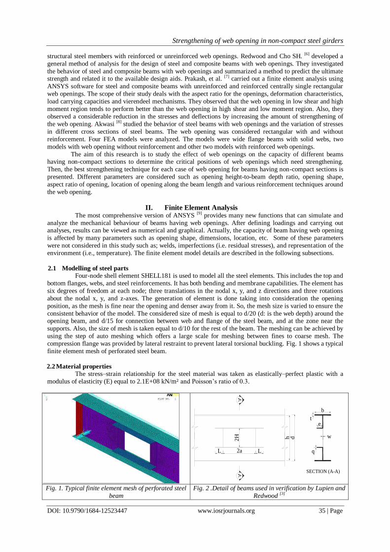
compression flange was provided by lateral restraint to prevent lateral torsional buckling. Fig. 1 shows a typical
finite element mesh of perforated steel beam.
2.2 Material properties
The stress–strain relationship for the steel material was taken as elastically–perfect plastic with a
modulus of elasticity (E) equal to 2.1E+08 kN/m² and Poisson’s ratio of 0.3.
2H
L2aL
h d
e
q
t
b
w
SECTION (A-A)
Fig. 1. Typical finite element mesh of perforated steel
beam
Fig. 2 .Detail of beams used in verification by Lupien and
Redwood [3]
Strengthening of web opening in non-compact steel girders
DOI: 10.9790/1684-12523447 www.iosrjournals.org 36 | Page
Table 1: Cross section dimensions of beams tested by Lupien and Redwood [3]
Beam d
(in) b (in) t (in)
w
(in)
h
(in)
q
(in)
e
(in)
2a
(in)
2H
(in) L (in)
RL2 20.56 6.88 0.392 0.253 19.78 0.368 2.281 33.75 13.50 4.44
RL3 20.63 7.06 0.377 0.252 19.88 0.368 2.281 22.50 9.00 4.00
Table 2: Material properties of beams which were tested by Lupien and Redwood [3]
Beam Yield stress fy (kip/in²)
Flanges Web Reinforcement
RL2 54.17 58.67 43.31
RL3 53.23 58.26 43.78
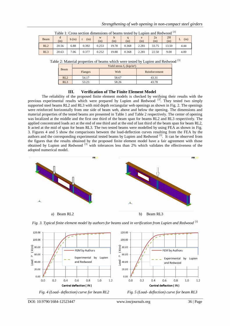
III. Verification of The Finite Element Model The reliability of the proposed finite element models is checked by verifying their results with the
previous experimental results which were prepared by Lupien and Redwood [3]. They tested two simply
supported steel beams RL2 and RL3 with mid depth rectangular web openings as shown in Fig. 2. The openings
were reinforced horizontally from one side of beam web, above and below the opening. The dimensions and
material properties of the tested beams are presented in Table 1 and Table 2 respectively. The center of opening
was localized at the middle and the first one third of the beam span for beams RL2 and RL3 respectively. The
applied concentrated loads act at the end of one third and at the end of last third of the beam span for beam RL2, It acted at the mid of span for beam RL3. The two tested beams were modelled by using FEA as shown in Fig.
3. Figures 4 and 5 show the comparisons between the load-deflection curves resulting from the FEA by the
authors and the corresponding experimental tested beams by Lupien and Redwood [3]. It can be observed from
the figures that the results obtained by the proposed finite element model have a fair agreement with those
obtained by Lupien and Redwood [3] with tolerances less than 2% which validates the effectiveness of the
adopted numerical model.
a) Beam RL2 b) Beam RL3
Fig. 3. Typical finite element model by authors for beams used in verification from Lupien and Redwood [3]
Fig. 4 (Load- deflection) curve for beam RL2
Fig. 5 (Load- deflection) curve for beam RL3
Experimental by Lupien
and Redwood
Experimental by Lupien
and Redwood
Strengthening of web opening in non-compact steel girders
DOI: 10.9790/1684-12523447 www.iosrjournals.org 37 | Page
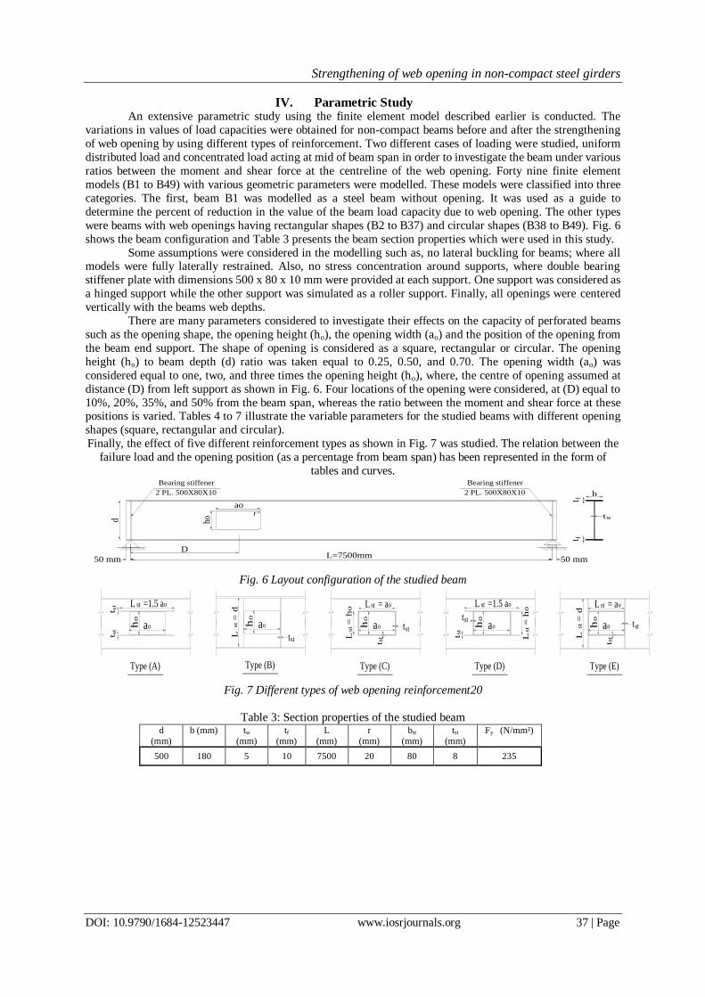
IV. Parametric Study An extensive parametric study using the finite element model described earlier is conducted. The
variations in values of load capacities were obtained for non-compact beams before and after the strengthening
of web opening by using different types of reinforcement. Two different cases of loading were studied, uniform
distributed load and concentrated load acting at mid of beam span in order to investigate the beam under various
ratios between the moment and shear force at the centreline of the web opening. Forty nine finite element
models (B1 to B49) with various geometric parameters were modelled. These models were classified into three
categories. The first, beam B1 was modelled as a steel beam without opening. It was used as a guide to
determine the percent of reduction in the value of the beam load capacity due to web opening. The other types
were beams with web openings having rectangular shapes (B2 to B37) and circular shapes (B38 to B49). Fig. 6
shows the beam configuration and Table 3 presents the beam section properties which were used in this study.
Some assumptions were considered in the modelling such as, no lateral buckling for beams; where all models were fully laterally restrained. Also, no stress concentration around supports, where double bearing
stiffener plate with dimensions 500 x 80 x 10 mm were provided at each support. One support was considered as
a hinged support while the other support was simulated as a roller support. Finally, all openings were centered
vertically with the beams web depths.
There are many parameters considered to investigate their effects on the capacity of perforated beams
such as the opening shape, the opening height (ho), the opening width (ao) and the position of the opening from
the beam end support. The shape of opening is considered as a square, rectangular or circular. The opening
height (ho) to beam depth (d) ratio was taken equal to 0.25, 0.50, and 0.70. The opening width (ao) was
considered equal to one, two, and three times the opening height (ho), where, the centre of opening assumed at
distance (D) from left support as shown in Fig. 6. Four locations of the opening were considered, at (D) equal to
10%, 20%, 35%, and 50% from the beam span, whereas the ratio between the moment and shear force at these positions is varied. Tables 4 to 7 illustrate the variable parameters for the studied beams with different opening
shapes (square, rectangular and circular).
Finally, the effect of five different reinforcement types as shown in Fig. 7 was studied. The relation between the
failure load and the opening position (as a percentage from beam span) has been represented in the form of
tables and curves.
50 mmL=7500mm
50 mm
d ho
aor
D
Bearing stiffener
2 PL. 500X80X10 b
t
t
w
ft f
Bearing stiffener
2 PL. 500X80X10
Fig. 6 Layout configuration of the studied beam
t L
=
d
t
t
t
t L
= ht
Type (A) Type (B) Type (C) Type (D) Type (E)
st
st
st st
st
st stst
L
=
dst
L = astt s
t
tst
L =1.5 ast o
h ao
o
t st
h ao
o
o
h ao
o
h ao
o
h ao
o
L =1.5 ast o
o
L = ast o
L
= h
st
o
Fig. 7 Different types of web opening reinforcement20
Table 3: Section properties of the studied beam d
(mm)
b (mm) tw
(mm)
tf
(mm)
L
(mm)
r
(mm)
bst
(mm)
tst
(mm)
Fy (N/mm²)
500 180 5 10 7500 20 80 8 235

Strengthening of web opening in non-compact steel girders
DOI: 10.9790/1684-12523447 www.iosrjournals.org 38 | Page
Tables 4 to 7: Summary of different parameters considered in the study of beams with square, rectangular or
circular openings
The value of failure load for each model from the aforementioned models was determined with
considering the web opening without reinforcement. After that it is compared with the failure load for
unperforated beam (B1). All affected models due to the web opening were strengthened by using one type from
five different stiffeners methods, as shown in Figure (7). The stiffeners are classified to five types A, B, C, D
and E. Where types A, B and C refer to extended horizontal stiffener above and below the opening, extended vertical stiffener left and right the opening and horizontal and vertical stiffener around the opening without
extension (sleeve reinforcement) respectively. while, types D and E refer to horizontal stiffener above and
below the opening in addition to un-extended vertical stiffener left and right the opening and extended vertical
stiffener left and right the opening in addition to un-extended horizontal stiffener above and below the opening
respectively. All stiffeners have the same dimensions (outstand dimensions, bst=80mm and thickness, tst =8mm).
The effect of each type from the maintained stiffeners types is studied to determine the best technique to
strengthen the non-compact perforated beams.
V. Results And Discussions First, the maximum load capacity of non-compact unperforated beam (B1) under the effect
of different two cases of loading, uniform distributed load and concentrated load at mid of the beam
span is found equal to 40.73kN/m and 157.0kN respectively. The maximum load capacities for non-
compact perforated beams (B2) to (B49) are obtained from the FEA and are plotted as percent from
the corresponding load capacity for the unperforated beam (B1) as shown in Figs (11) to (17).
Second, these results are studied to demonstrate the effect of the web opening in reducing and
minimizing the load capacity for each perforated beam according to the opening shape and location.
Third, the beams affected due to the web opening are determined. They are tacked into consideration
to study the effect of the different types of reinforcements for each case to determine the best
reinforcement system that can be used to restore the loss from the beam capacity.
5.1 Perforated beams without reinforcement under uniform distributed load
As illustrated in Figures (11) and (14), it is shown that the load capacity of the perforated
beam is not affected by the opening shape (square, rectangular or circular) if the opening height-to-
beam depth ratio (ho/d) equals 0.25 when the opening is located at any position from the beam span
unless at mid of the beam span. The same phenomenon can be noticed for ho/d =0. 50 but only for
square or circular opening, as shown in Figure (12). While, a significant reduction in the beam load
capacity is occurred for rectangular opening located at critical shear zone (near end support) with
ho/d =0.50.
This can be explained by the moment-shear interaction equation (EQ.1) which consists of
the summation of ratios between the actual straining actions (moment and shear) and the
Table 7 : Beams having
circular opening
(with diameter =h0)
Beam
No.
B 38
0.25
10
B 39 20
B 40 35
B 41 50
B 42
0.50
10
B 43 20
B 44 35
B 45 50
B 46
0.70
10
B 47 20
B 48 35
B 49 50
Table 4 : Beams with square or
rectangular opening and ho/d
=0.25
Beam
No.
B2
1
10
B3 20
B4 35
B5 50
B6
2
10
B7 20
B8 35
B9 50
B10
3
10
B11 20
B12 35
B13 50
Table5 : Beams with
square or rectangular
opening and ho/d =0.50
Beam
No.
B14
1
10
B15 20
B16 35
B17 50
B18
2
10
B19 20
B20 35
B21 50
B22
3
10
B23 20
B24 35
B25 50
Table 6 : Beams with
square or rectangular
opening ho/d =0.70
Beam
No.
B26
1
10
B27 20
B28 35
B29 50
B30
2
10
B31 20
B32 35
B33 50
B34
3
10
B35 20
B36 35
B37 50

Strengthening of web opening in non-compact steel girders
DOI: 10.9790/1684-12523447 www.iosrjournals.org 39 | Page
corresponding cross section strength (bending and shear capacities). Therefore, the decrease of cross
section strength against bending or shear minimizes the ability to resist a corresponding straining
action (moment or shear) and the total capacity of beam is decreased as such:
= R3 where [R≤1.0] (EQ.1)
Where:
Mu: the factored bending moment at opening centreline
Vu: the factored shear at opening centreline
Mm: the maximum nominal bending capacity at the location of opening centreline under pure bending;
it occurs when Vu= 0.
Vm: the maximum nominal shear capacity at the location of an opening centreline under pure shear; it
occurs when Mu= 0.
Ø: the resistance factor, equal to 0.90 for steel beams.
Fig. 8 Perforated section force distribution [10]
Consequently, the load capacity of beam is not affected by the opening with square or circular shape when the ratio between opening height-to-beam depth (ho/d) up to 0.50 when it is located at any position from
the beam span unless about mid of span. This is because the remaining part from the web area after opening as
shown in Figure (8) is enough to resist the applied shear without any reduction in the section capacity. However,
the stiffness of the beam section decreased by the association of the cross sections along the beam length
especially when the opening is located at mid span.
Over and above, the increase of the opening width decreases the overall capacity of the perforated
beam especially, when the opening is located near the critical shear zone because, the increase in opening width
produces an additional moment (vierendeel moment) which is induced due to shear transfer along opening
width, as shown in Figure 8. Therefore, failure of steel beams with web openings are frequently governed by
Vierendeel collapse mechanism that occurs due to a change rate in the bending moment distribution (and
consequently, the shear force) along the opening [10]. This increase in the bending moment is usually resisted by upper and lower “Tees” through their respective local bending strengths, Figure 8 [10]. The web of the beam is
“thick” and is not prone to buckling in shear under the action of the loads, the collapse is likely to be initiated by
the formation of four plastic hinges, near the four corners of the hole in the web above and below the openings
due to additional virendeel moment as shown in Figure (9).
However, when the edges of the openings are un-stiffened, the non-compact or slender
sections are susceptible to local buckling of the web-flange section (T section) at the horizontal edge
that is in compression due to the global bending action as shown in Figure 10. The opening in such
cases may be stiffened or only the elastic capacity of the web-flange section may be used. It is
necessary to check for the compression zone stability of the large rectangular openings in high
moment regions. This is carried out by treating it as an axially loaded column with effective length
equal to that of the length of the opening (ao) [10].
Fig.9.Details of 4-Plastic hinges formed in web Fig. 10 local buckling of unstiffened web at the opening

Strengthening of web opening in non-compact steel girders
DOI: 10.9790/1684-12523447 www.iosrjournals.org 40 | Page
For the same reason, the reduction in load capacity was even more pronounced for all
perforated beams with different web opening shapes and with ho/d =0.70, as shown in Figure (13). It
is observed that at a big ratio of width-to-height of opening, the loss in uniform load capacity of the beam is sharply decreased when the opening is located near support, i.e. at high shear zone (at
D/L=10% and 20%) due to the increase in the additional moment (vierendeel moment) as discussed
before. When providing the same opening around mid-span, i.e. at high bending moment zone (at
D/L=35% and 50%) leads to slight loss in the uniform load capacity. This observation supports the
recommendations of several researchers to provide the web opening around the middle of beam span
for beams subjected to uniform load, where the loss in the uniform load capacity will be less than the
other locations. From Figures (12) to (14), it is illustrated that when the opening at high shear zone
(D/L = 10%) and has circular shape with (ho/d) equal to 0.50 and 0.70 the reduction in the uniform
load capacity of beam is less about only 1%. For square opening with the same dimensions and
geometric conditions, the reduction is about 20-40%. The same thing can be illustrated when the
opening at high moment zone (D/L=50%) but with little differences. This confirms that the beams with circular openings are presenting higher ultimate loads than the other investigated opening
geometries especially, at high shear zone. Figures 25 to 27 illustrate an evolution of the Von Mises
stress distribution for specimens B30, B42 and B46. It is observed that the four plastic hinges were
formed in the web about opening, for any opening shape.
5.2 Perforated beams without reinforcement under concentrated load at mid span of beam
According to the nature of this case of loading, the distribution of shear force is constant
along the beam span but the bending moment increases gradually to a maximum at mid span of
beam. Therefore, the additional moment (vierendeel moment) which resulted due to shear transfer
along opening width, will not be different due to the variation of the opening positions. Therefore, as
expected, the beams with rectangular openings produce the smaller ultimate loads, i.e. about 30%
less than the equivalent beams with square or circular openings as shown in Figures (15) to (18). In these beams, the Vierendeel collapse mechanism was observed in all the beams with rectangular
openings independent of the beam opening position along the span. It should also be pointed out that
the beams with rectangular openings located at a distance 0.50 L from the supports reached ultimate
loads less than their equivalent beams with rectangular openings located at a distance 0.1 L from the
supports. This issue is easily explained by the fact that the Vierendeel mechanism formation is
intimately associated to the shear force magnitude at the opening, i.e. increasing the shear force
magnitude at the opening reduces the beam collapse load.
Figures (15) and (18) observed that the value of beam ultimate load is not affected due to
web opening with square or circular shape when the ratio between height of opening and beam depth
(ho/d) up to 0.50 at any position along the beam span except at mid span. The ultimate load at this
point reduces between 7% and 17 % for square opening as well as by 4 % and 16 % for circular opening with (ho/d) ratio equals 0.25 and 0.50 respectively. So, it is recommended that the opening
must not carry out at the positions of load concentrations along the beam span.
It can be observed from Figure (17) that the beam with square opening and (ho/d) equal to
0.70 presents a collapse mode combining the Vierendeel collapse mechanism with a load application
point bending collapse. For these beams, openings located at a point distancing 0.50 L (where L
represents the beam span) from the supports produced ultimate loads less than beams with openings
at 0.10 L from the supports. This fact indicates that the bending stresses begin to play a significant in
theses beam ultimate loads. Beams with circular openings presented two distinct collapse modes.
The beams with openings located at a distance 0.10 L from the supports had their collapse associated
to a Vierendeel mechanism collapse. The Vierendeel moment is minimum in case of circular opening
where the translation of shear on both sides of the opening is very smooth. Therefore the circular
geometry enables the beams to sustain higher ultimate loads, similar to the ultimate loads of beams without openings. And the opening did not influence the beam collapse load. Beams with circular
openings located at 0.50 L from the supports had their collapse as an interaction of Vierendeel
mechanism and load application point bending collapse. Figure 18 presents the variation of the
ultimate load at the web opening center.
Moreover, it is illustrated that if the perforated beam has a rectangular opening with various
rectangularity ratios (1:2 or 1:3) and the opening height-to-beam depth ratio (ho/d) up to 0.70; then
the load capacity decreased by about 60% to 80% from the beam capacity. Also it is observed that
the position of opening along the beam span does not affect the beam capacity as shown in Figure
(17) because the additional vierendeel moment in this case is high and steady along the beam span
due to the constancy of the shear distribution along the beam span.

Strengthening of web opening in non-compact steel girders
DOI: 10.9790/1684-12523447 www.iosrjournals.org 41 | Page
5.3 Perforated beams with reinforcement under uniform distributed or concentrated load
Figures (11) to (18) demonstrate that the failure load has a high reduction in its value due to
the existence of square or rectangular opening with height equal to 0.5-0.7d. Despite this fact, there are situation where the use of these openings cannot be avoided. For these cases the use of stiffeners
welded at the edges of the web openings is strongly recommended by practice and design standards.
Aiming to verify the structural efficiency of these stiffeners, sixteen beams were simulated with
different stiffener types (A, B, C, D and E). They have the same characteristics of some of the
numerical simulations performed in the parametric analysis (i.e. Specimens B22 to B37). The
stiffeners were modelled with the geometrical characteristics presented in Table 3, and are illustrated
in Figure 7. Figures (26) to (30) show the variation in the von Mises stresses for perforated beam
(B30) without stiffeners and with stiffeners types A, B, C and D. It indicates that the use of stiffeners
enables a better stress redistribution along the web openings which leads to an increase of the beams
load carrying capacity. The relation between the uniform failure loads for the strengthened beams
and the position of the opening as a percentage from the beam span is shown in Figures (19) to (23). Table (8) presents a comparison of the ultimate loads for beams with and without stiffeners for the
configuration related to specimens B22 to B37 subjected to concentrated load at mid of beam span.
The ultimate loads of the stiffened perforated beams increased with high rate especially for
beams that have openings near the critical shear region. For beams with opening near the region of
high moment, the ultimate load increases but with a little rate because the augmentation in load
capacity of the strengthened beam mainly depends on the improvement of the shear capacity of the
perforated section. When, the development of the shear capacity of the perforated section is
concerned on shear transfer along the opening width to the solid cross section of the beam at left and
right of the opening. This leads to decrease the additional moment (vierendeel moment) which
results due to shear transfer along the opening width. Therefore, the function of the horizontal
stiffener is to transfer and distribute the shear stresses to the solid beam section on both sides of the
opening. So, the usage of strengthening types (A) and (D) improves the capacity of the beam with higher ratio more than the other types. Regarding the failure loads shown in Figures (19) to (23) and
Table (8), it is obvious that the augmentations of ultimate load due to the use of each type of
reinforcements (A) or (D) are equal approximately. The percent of ultimate concentrated load of
specimen B31 without reinforced equals 41.56% but it increases to 88% and 92.8% for the same
beam with reinforcement type (A) or (D) respectively. So, it could be recommended the usage of
type (A) which refers to the extended horizontal reinforcement because it is an effective type to
compensate the strength loss of the beam at the perforated section and is more economic than type
(D).
Meanwhile, it is clear that type (B), which refers to extended vertical stiffener left and right
of the opening is inadmissible reinforcement system for any web opening at different positions. The
load capacity of the perforated beam having reinforcement type (B) decreases than without reinforcement as shown in Table (8).This could be explained that the vertical stiffener causes stress
concentration at the region around the web opening which leads to early failure as shown in Figures
(28) and (31). In general, it could be observed from Figures (19) to (23) that the stiffeners have high
efficient contribution and a substantial improvement of the ultimate loads of beams with square and
rectangular openings with (ho/d) equals 0.50 only. As shown in Figure (32) the failure of beam is
governed by bending mechanism at mid span point under concentrated load. For all beams having
rectangular openings with (ho/d) equal to 0.70 at the critical shear zone, the use of stiffeners
increases the ultimate load about 25% from their maximum values as shown in Figures (22) and (23)
and Table (8) and as shown in Figures (33) and (34) where the failure of beam (B31) without or with
reinforcement type (D) is governed by Vierendeel mechanism at the opening position. So, it is
recommended not to use any rectangular opening with (ho/d) higher than 0.50 at the critical shear
zone.
VI. Conclusions Last searches used experimental, numerical and analytical techniques to study the effect of web
openings on the capacity of different beams with compact sections. A little of these searches considered the non-
compact sections. A comprehensive finite element investigation on non-compact perforated beams with
rectangular, square and circular web opening shapes was carried out. The FE model was validated against
experimental work found in the literature and presented herein. Two different cases of loading were considered:
uniform load and one concentrated load at mid span. Analyses of perforated sections with different web opening
configurations show how the Vierendeel mechanism is affected not only by the size, but also by the shape of the web opening and its location along the beam span. The effects of the critical web opening length and depth as

Strengthening of web opening in non-compact steel girders
DOI: 10.9790/1684-12523447 www.iosrjournals.org 42 | Page
well as the web opening shape are presented through a parametric FE investigation. The investigation of the web
openings presents some positive results that updates the current knowledge. Based on the FE model,
improvements to the assessment of load carrying capacities of steel beams with large web openings are obtained by careful observation of plastic hinge formation at both sides of the opening. The effect of different opening
stiffener systems is investigated and the best strengthening technique for each case of web opening was
performed. The main conclusions obtained from this research can be summarized into the following:
There is no variation observed in experimental values and finite element analysis results obtained by
ANSYS.
The load capacity of the perforated beam is not affected by the opening shape (square, rectangular or
circular) if the opening height does not exceed 25% of beam depth and the opening is located at any
position along the beam span unless at the mid of beam span.
The same phenomenon can be concluded for web openings having a height equal to half of the beam depth
(ho/d =0. 50) only for cases of square and circular opening shapes.
The load capacity of the perforated beam has a significant reduction, when a rectangular opening with height not exceeding 50% of beam depth and located at the critical shear zone.
Increasing the opening width decreases the overall capacity of the perforated beam especially, when the
opening is located near the critical shear zone due to the effect of additional moment (Vierendeel moment)
which is induced due to shear transfer along the opening width. It is higher in case of rectangular openings
than in square ones, while it is least for circular openings.
It is observed that the failure of perforated steel beams is frequently governed by Vierendeel collapse
mechanism due to the additional Vierendeel moment which is usually resisted by upper and lower “Tees”
through their respective local bending strengths.
It is necessary to check the compression zone stability of large rectangular openings in high moment
regions. This is carried out by treating it as an axially loaded column with effective length equal to that of
the opening length with T-section. The strength of this column is governed by its buckling behavior and the local buckling of its T-section.
Increasing the opening width-to-height ratio (ao/ho) at the first third of the span sharply decreases the
capacity of the perforated section while increasing this ratio at the middle third of the span slightly
decreases the capacity of perforated section.
It is recommended that the opening must not be done at the positions of load concentrations along the
beam span. Because the load capacity is sharply decreased at this section.
The load capacity of the perforated beam having a rectangular opening with various rectangularity ratios
(1:2 or 1:3) and opening height-to-beam depth ratio (ho/d) up to 0.70 is decreased about 60-80% from its
full capacity.
The beam with circular opening presents an increase of the ultimate load that cannot be discarded. Despite
this beneficial effect, the Vierendeel mechanism is still the controlling collapse mode for these beams.
Providing a single circular opening with diameter-to-beam depth ratio (ho/d) up to 70% has a negligible
effect on the capacity of the beam except at mid span when it is reduced by 8% -12 %. Therefore it is
recommended to use circular openings where they present a higher ultimate load for the perforated beam
than other investigated opening geometries.
The usage of two extended horizontal stiffeners upper and lower the opening is the most effective type of
reinforcement to compensate the strength loss of the beam at the perforated section. Because it transfers
the shear force along the opening to the regions besides it, therefore, Vierendeel moment is decreased.
Also it restrains the out-of-plane deformations of the horizontal edges of the opening. Hence the buckling
strength of the reminder T-section in the compression side is increased.
The usage of any type of horizontal stiffeners especially, the extended types A or D increases the load
capacity of the perforated beam with a high rate at critical shear zone (at D/L=10, 20%) than at high moment zones (at D/L=35, 50%)
Providing an unreinforced rectangular web opening with height to beam depth ratio (ho/d) more than 0.25
and width-to-height ratio (ao/ho) up to 0.3 sharply decreases the shear capacity at the perforated section.
Reinforcement of the web opening with vertical stiffeners has negligible effect on the capacity of the
perforated section; it may cause stress concentration around the web opening which leads to early failure.
Thus, it is not recommended to use vertical stiffeners to compensate the loss strength of the beam at the
perforated section.

Strengthening of web opening in non-compact steel girders
DOI: 10.9790/1684-12523447 www.iosrjournals.org 43 | Page
Fig. 11 max. distributed load capacity for unreinforced
beams having square or rectangular openings with
(ho/d = 0.25)
Fig. 12 max. distributed load capacity for unreinforced
beams having square or rectangular openings with (ho/d
= 0.50)
Fig. 13 max. distributed load capacity for unreinforced
beams having square or rectangular openings with
(ho/d = 0.70)
Fig. 14 max. distributed load capacity for unreinforced
beams having circular openings.
Fig. 15 max. concentrated load capacity for
unreinforced beams having square or rectangular
openings with (ho/d = 0.25)
Fig. 16 max. concentrated load capacity for
unreinforced beams having square or rectangular
openings with (ho/d = 0.50)

Strengthening of web opening in non-compact steel girders
DOI: 10.9790/1684-12523447 www.iosrjournals.org 44 | Page
Fig. 17 max. concentrated load capacity for unreinforced beams having square or rectangular
openings with (ho/d = 0.70)
Fig. 18 max. Concentrated load capacity for unreinforced beams having circular openings.
Fig. 19 max. distributed load capacity for perforated
beams with (ho/d = 0.50 & ao/ho =2) due to different
stiffeners
Fig. 20 max. distributed load capacity for perforated
beams with (ho/d = 0.50 & ao/ho =3) due to different
stiffeners
Fig. 21 max. distributed load capacity for perforated
beams with (ho/d = 0.70 & ao/ho =1) due to different
stiffeners
Fig. 22 max. distributed load capacity for perforated
beams with (ho/d = 0.70 & ao/ho =2) due to different
stiffeners

Strengthening of web opening in non-compact steel girders
DOI: 10.9790/1684-12523447 www.iosrjournals.org 45 | Page
Fig. 23 max. distributed load capacity for perforated
beams with (ho/d = 0.70 & ao/ho =3) due to different
stiffeners
Fig. 24 Von Mises stresses (kN/m2) for beam has a
circular opening with (ho/d = 0.50) without
reinforcement
Fig. 25 Von Mises stresses (kN/m2) for beam has a
circular opening with (ho/d = 0.70) without
reinforcement
Fig.26 Von Mises stresses (kN/m2) for beam has a
rectangular opening with (ho/d = 0.70 & ao/ho =2) at
(D/L=10%) and without reinforcement
Fig. 27 Von Mises stresses (kN/m2) for beam has a
rectangular opening with (ho/d = 0.70 & ao/ho =2) at
(D/L=10%) and with reinforcement type (A)
Fig. 28 Von Mises stresses (kN/m2) for beam has a
rectangular opening with (ho/d = 0.70 & ao/ho =2) at
(D/L=10%) and reinforcement type (B)
Strengthening of web opening in non-compact steel girders
DOI: 10.9790/1684-12523447 www.iosrjournals.org 46 | Page
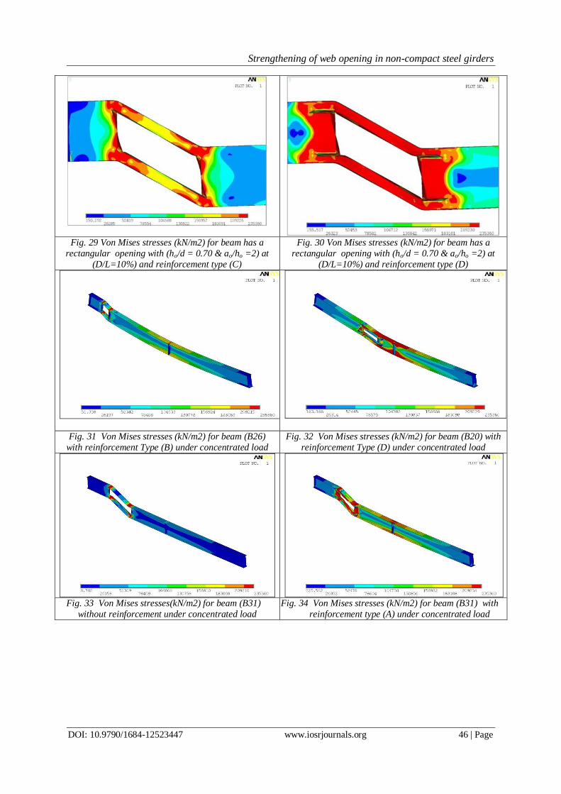
Fig. 29 Von Mises stresses (kN/m2) for beam has a
rectangular opening with (ho/d = 0.70 & ao/ho =2) at
(D/L=10%) and reinforcement type (C)
Fig. 30 Von Mises stresses (kN/m2) for beam has a
rectangular opening with (ho/d = 0.70 & ao/ho =2) at
(D/L=10%) and reinforcement type (D)
Fig. 31 Von Mises stresses (kN/m2) for beam (B26)
with reinforcement Type (B) under concentrated load
Fig. 32 Von Mises stresses (kN/m2) for beam (B20) with
reinforcement Type (D) under concentrated load
Fig. 33 Von Mises stresses(kN/m2) for beam (B31)
without reinforcement under concentrated load
Fig. 34 Von Mises stresses (kN/m2) for beam (B31) with
reinforcement type (A) under concentrated load

Strengthening of web opening in non-compact steel girders
DOI: 10.9790/1684-12523447 www.iosrjournals.org 47 | Page
Table 8: Percentage of failure loads for beams B22 to B37 subjected to concentrated load with
reinforcement
Beam
number
% Failure load ( % from failure load of unperforated beam)
Un-reinforced
opening
opening with different reinforced systems
Type (A) Type (B) Type (C) Type (D) Type (E)
B 22 88.54 100.00 78.98 100.00 100.00 100.00
B 23 85.67 100.00 77.71 100.00 100.00 100.00
B 24 77.07 96.82 74.52 98.73 98.73 93.63
B 25 69.17 78.84 65.34 75.32 78.77 75.82
B 26 97.32 100.00 75.61 100.00 100.00 100.00
B 27 92.19 100.00 74.52 100.00 100.00 100.00
B 28 83.79 98.09 70.06 90.45 100.00 99.36
B 29 63.94 71.07 56.05 68.79 71.66 70.43
B 30 41.72 87.90 36.31 63.57 94.59 72.61
B 31 41.56 88.09 36.31 63.06 92.87 74.20
B 32 39.78 75.80 35.03 63.06 76.43 72.29
B 33 37.58 64.01 34.39 60.03 64.01 60.86
B 34 24.84 69.87 23.57 43.63 74.52 44.59
B 35 24.36 66.69 23.57 42.68 72.61 43.95
B 36 24.20 63.06 23.38 41.08 63.06 44.52
B 37 24.20 53.34 22.77 50.48 53.34 49.36
Acknowledgements The authors acknowledge the effort presented by Prof. Dr. Abd El Moniem Amin the Professor of steel
structures and bridges, Civil Eng. Department, Faculty of Eng. Mataria, Helwan University for his supervision
of Mahmoud’s master Thesis [11] which represent the main reference of this research work during the period
from 1/2012 to 8/2013.
References [1]. Congdon, J. G. and Redwood, R.G. “Plastic behavior of beams with reinforced holes”, Journal of the Structural
Division, ASCE, Vol. 96, No. ST9, Proc. Paper 7561, September 1970, pp.1933-1956.
[2]. Cooper P. B. and Snell R. R. “Tests on beams with reinforced web openings”, Journal of the Structural Division 1972; 98- ST3:
612-632.
[3]. Lupien R. and Redwood R. G. “Steel beams with web openings reinforced on one side”, The National Research Council of Canada,
Can. J. Civ. Eng. 1978; 5: 451-461.
[4]. Darwin D. “Steel and composite beams with web openings - American Institute of Steel Construction’’ Steel Design guide series
1990; No. 2, Chicago, IL.
[5]. American Institute of steel construction. Manual of steel construction: Load and resistance factor design specification for structural
steel buildings. AISC-LRFD, 2005.
[6]. Redwood R. G. and Cho SH. “Design of steel and composite beams with web openings”, J. construction steel 1993; 25:23-41.
[7]. Prakash B. D., Gupta L. M., Pachpor P. D., and Deshpande N. V. “Strengthening of steel beam around rectangular web openings”,
International Journal of Engineering Science and Technology (IJEST) 2011, ISSN: 0975-5462, Vol.3 No.2:1130-1136.
[8]. Akwasi M. A. “Behavior of wide flange beams with reinforced web openings” M.Sc. Thesis, Southern Illinois University
Carbondale, 2012.
[9]. ANSYS, finite element program, Swanson Analysis System, Inc., Release 12.1, 2009.
[10]. Chung K. F., Liu T. C.H. and Ko, A.C.H., 2003 “Steel beams with large Web openings of various shapes and sizes: an
empirical design method using a generalized moment-shear interaction curve”. Journal of Constructional Steel
Research, 59, 1177-1200
[11]. Mahmoud S. M. “Strengthening of web openings in steel girders” M.Sc. Thesis, Helwan University Cairo, 2015.


![Static and Dynamic Analysis Web Opening of Steel Beams is the efficient design of beams girders with web opening. ... Redwood and Cho [5], ... investigation on steel beams with web](https://static.fdocuments.us/doc/165x107/5ac2ffa07f8b9a333d8b9788/static-and-dynamic-analysis-web-opening-of-steel-beams-is-the-efficient-design-of.jpg)