STRENGTHENING OF STRUCTURAL STEEL CHANNELS BY …
13
Journal of Engineering Science and Technology Vol. 15, No. 2 (2020) 1079 - 1091 © School of Engineering, Taylor’s University 1079 STRENGTHENING OF STRUCTURAL STEEL CHANNELS BY DIFFERENT CFRP WRAPPING CONFIGURATIONS-FINITE ELEMENT ANALYSIS MOHAMMED J. HAMOOD*, MAHA GHALIB GHADDAR, ZINAH ASAAD ABDUL HUSAIN Civil Engineering Department, University of Technology, Baghdad, Iraq *Corresponding Author: [email protected] Abstract The structural steel open channel sections, which are widely used in many constructions have been designed with the main purpose of giving large resistance to bending while the torsional strengths are known to be relatively small. Accordingly, to increase the flexural strength and stiffness of this structural section, Carbon Fibre Reinforced Polymer (CFRP) has been used. The present study is to evaluate the performance of strengthening of the structural steel channel using different schematics of CFRP wrapping configurations. Furthermore, it aims to check out the optimum scheme to resist buckling using a finite element approach. The results of the analysis indicate that the adopted technic of a total number of five models including the control model is successful. The mode of failure is different and relies on the scheme of CFRP configurations. Models with skin CFRP have a combined action of bending and torsion failure mode. Besides, their ultimate load capacity is less than the closed scheme of CFRP but greater than that of the control model. When the number of CFRP layers becomes two and due to the orthogonal direction of the fibres, the flexural stiffness increases, the confinement effect provided by CFRP layers enhances the torsional stiffness of the model and decreases the vertical and lateral deflections. Consequently, the more number of CFRP layers, the more enhancement of buckling load capacity. The increase in the torsional stiffness offers sufficient resistance against the twisting; a matter that modifies the failure manner. This indicates that understanding the CFRP failure modes is useful in finding solutions for retarding the failures. Keywords: ANSYS, Buckling resistance, CFRP, Finite element analysis, Steel Section Channel, Strengthening.
Transcript of STRENGTHENING OF STRUCTURAL STEEL CHANNELS BY …

Journal of Engineering Science and Technology Vol. 15, No. 2 (2020) 1079 - 1091 © School of Engineering, Taylor’s University
1079
STRENGTHENING OF STRUCTURAL STEEL CHANNELS BY DIFFERENT CFRP WRAPPING
CONFIGURATIONS-FINITE ELEMENT ANALYSIS
MOHAMMED J. HAMOOD*, MAHA GHALIB GHADDAR, ZINAH ASAAD ABDUL HUSAIN
Civil Engineering Department, University of Technology, Baghdad, Iraq
*Corresponding Author: [email protected]
Abstract
The structural steel open channel sections, which are widely used in many
constructions have been designed with the main purpose of giving large
resistance to bending while the torsional strengths are known to be relatively
small. Accordingly, to increase the flexural strength and stiffness of this
structural section, Carbon Fibre Reinforced Polymer (CFRP) has been used. The
present study is to evaluate the performance of strengthening of the structural
steel channel using different schematics of CFRP wrapping configurations.
Furthermore, it aims to check out the optimum scheme to resist buckling using a
finite element approach. The results of the analysis indicate that the adopted
technic of a total number of five models including the control model is successful.
The mode of failure is different and relies on the scheme of CFRP configurations.
Models with skin CFRP have a combined action of bending and torsion failure
mode. Besides, their ultimate load capacity is less than the closed scheme of
CFRP but greater than that of the control model. When the number of CFRP
layers becomes two and due to the orthogonal direction of the fibres, the flexural
stiffness increases, the confinement effect provided by CFRP layers enhances the
torsional stiffness of the model and decreases the vertical and lateral deflections.
Consequently, the more number of CFRP layers, the more enhancement of
buckling load capacity. The increase in the torsional stiffness offers sufficient
resistance against the twisting; a matter that modifies the failure manner. This
indicates that understanding the CFRP failure modes is useful in finding solutions
for retarding the failures.
Keywords: ANSYS, Buckling resistance, CFRP, Finite element analysis, Steel
Section Channel, Strengthening.
1080 M. J. Hamood et al.
Journal of Engineering Science and Technology April 2020, Vol. 15(2)
1. Introduction
Strengthening and retrofitting using Carbon fibre reinforced polymer (CFRP)
composites have been of increasing interest and acceptance in civil engineering
applications. This is due to their high strength-to-weight ratio, good durability, and
to the combination of adhesive bonding of a flexible shape. The effectiveness of
using externally bonded CFRP composites to improve the strength of structural
steel members has been dealt with by many researchers [1-4]. Teng et al. [5]
presented a critical review and interpretation of the available research studies on
CFRP-strengthened steel structures. Ekiz and El-Tawil [6] studied the buckling
behaviour of the steel members strengthened with CFRP wraps and they proposed
a strengthening method that can provide enough lateral support to these members
to allow them to yield in compression and to continue deforming in further than
elastically. Peiris [7] found that when using ultra-high-modulus of CFRP to
strengthen steel members, gave strength capacity more than that involved with
normal CFRP. Kabir et al. [8] studied the effect of CFRP strip layers’ orientation
on improving the bearing capacity of the structural circular hollow steel member.
They found that using double CFRP strips along with one transverse layer gave
strength capacity and stiffness more than that with one CFRP layer along with two
layers in the transverse direction. Siwowski and Siwowska [9] found that the failure
modes of the strengthened beams including CFRP plate debonding or plate rupture,
depend on the strengthening system and some parameters, such as that of CFRP
modulus of elasticity, endplate anchoring, and of plate prestressing level.
Selvaraj et al. [10] conducted an experimental investigation to study the strength
enhancement in the structural steel channel section strengthened by different CFRP
wrapping configurations. The researchers found that the effectiveness of the closed
section can be further improved by increasing the unidirectional CFRP layers prior
to the final wrapping by the bidirectional fibres. This study was extended by
Selvaraj and Madhavan [11, 12] to improve the failure modes. They further found
that CFRP strengthening techniques can significantly improve the flexural moment
capacity compared to the bare open specimen. Such an improvement can be done
by converting the lateral-torsional buckling (LTB) mode of failure to failure due to
yielding. In addition, they found that the closed wrapped configuration with an
additional layer of bi-directional CFRP fabric provides the higher strength and
stiffness compared to the control and skin wrapped specimen due to the
confinement of hoop directional fibres.
Most of the available studies focused on strengthening or retrofitting using CFRP
for I or hollow steel sections and a few for channel steel sections. Consequently, it is
important to study experimentally and numerically the performance of the channel
steel sections strengthened or retrofitted by CFRP. Furthermore, it has been noticed
that the closed-form section of the channels wrapping by CFRP instead of the open
channel section is necessary to increase the torsional resistance of these sections.
The aim of the present study is to examine the performance of the structural steel
channel that is strengthened by different CFRP wrapping configurations using a finite
element analysis. The main parameter that should be taken into account is the number
of CFRP layers and configuration to reach the optimum scheme of CFRP; a matter
that increases the strength capacity of the channel and improves the behaviour and
buckling mode of failure by transforming the open cross-sections to close ones.

Strengthening of Structural Steel Channels by Different CFRP . . . . 1081
Journal of Engineering Science and Technology April 2020, Vol. 15(2)
2. General Description of Test Specimens and Loading Condition
The studied numerical evaluation of specimen was for a standard channel steel
section with dimensions of 100×50 mm and 1400 mm long, web thickness of 5 mm,
and with an average top and bottom flange thickness of 7.5 mm. Four different
schemes of CFRP wrapped around the open channel and an additional one as a
control model for comparisons were adopted. The first scheme of CFRP was a skin
wrapped by keeping the steel section open with unidirectional and bidirectional.
The third model was closed and wrapped by single CFRP layer, and the fourth
model was also closed, but wrapped with double CFRP layers; Table 1 of list
descriptions about the model and CFRP properties: Thickness (0.25 mm), tensile
strength (4000 MPa), tensile modulus (240000 MPa) and elongation (1.8%).
Table 1. Model details
Model mark CFRP layer Description
C1 *NA Control
C2 One direction layer Skin open-wrap
C3 Two direction layer Skin open-wrap
C4 One layer Close-wrap
C5 Two layers Close-wrap
*Not applicable
The load was applied at the one-third of the span by two application points at
each 400 mm from simple supports with 100 mm overhang at both sides so that the
centre to centre span become 1200 mm as shown in Fig. 1(a). The vertical and
lateral deflection of the tested specimens was measured by LVDT (Linear Variable
Displacement Transducer) at the mid-span of the specimen, as shown in Fig. 1(b).
For more information about the test, refer to Selvaraj and Madhavan [11].
Fig. 1. Experimental setup: (a) Test specimen,
(b) Location of deflection measurements [11].
1082 M. J. Hamood et al.
Journal of Engineering Science and Technology April 2020, Vol. 15(2)
3. Numerical Evaluation by Finite Element Analysis Approach
Finite element method was selected for analysing the composite beam models by
ANSYS version 18.20 [13]. SOLID185 and SOLSH190 were adopted to simulate
the steel channel section and CFRP, respectively. The steel nodes at the interaction
with CFRP have the same nodes. Accordingly, there is no slip developed between
the contact surfaces where the glue is assumed to be enough to make them fully
interacted, and work as a unit. The accuracy of the solution as an applied load
follows the Newton-Raphson iterative method with 5% tolerance with
displacement control. The applied load was divided into sub-steps and the model
mesh was selected to reduce the solution time and give an accurate solution.
According to Selvaraj and Madhavan [11], the finite element simulation and
models are developed to match the actual experimental test data and conditions.
As reported previously, during the experimental loading process, there was not
any debonding or slip between the steel and CFRP; so, the method that adopted
common nodes between the steel and CFRP in the finite element numerical
simulation has a limited impact on the analytical results. The scheme and layout of
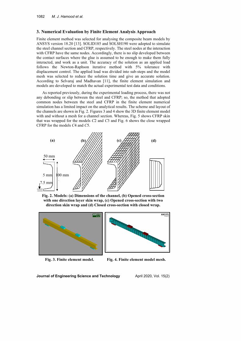
the channels are shown in Fig. 2. Figures 3 and 4 show the 3D finite element model
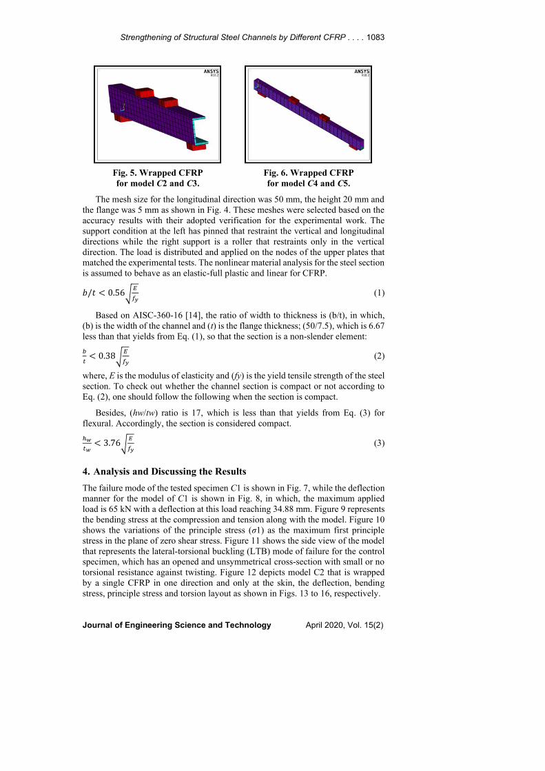
with and without a mesh for a channel section. Whereas, Fig. 5 shows CFRP skin
that was wrapped for the models C2 and C3 and Fig. 6 shows the close wrapped
CFRP for the models C4 and C5.
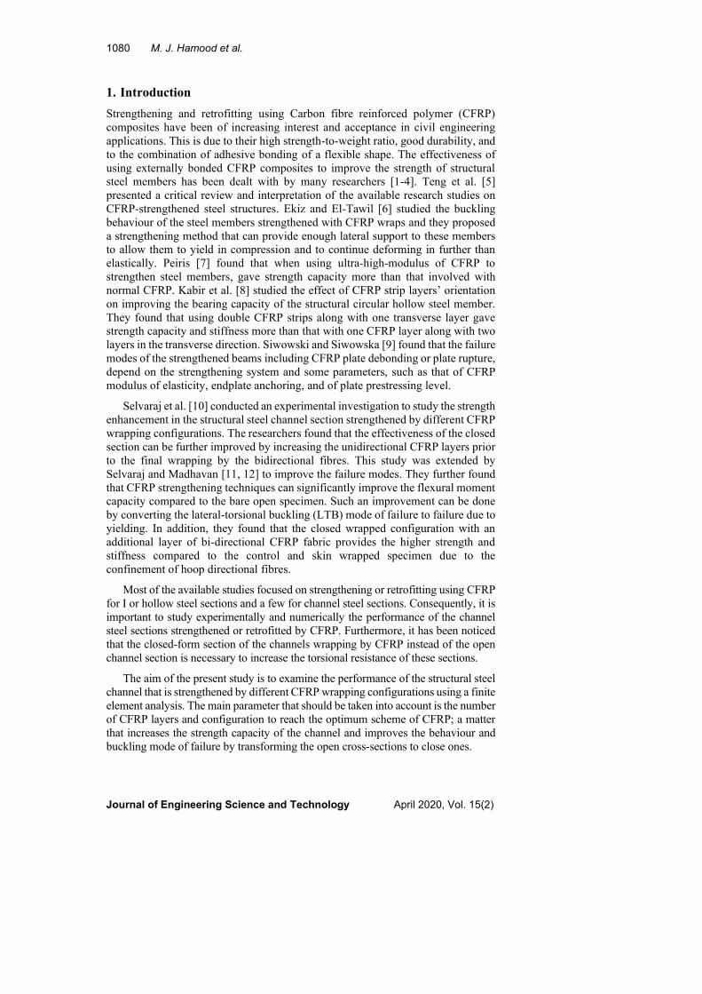
Fig. 2. Models: (a) Dimensions of the channel, (b) Opened cross-section
with one direction layer skin wrap, (c) Opened cross-section with two
direction skin wrap and (d) Closed cross-section with closed wrap.
Fig. 3. Finite element model. Fig. 4. Finite element model mesh.
(a) (b) (c) (d)
100 mm
50 mm
5 mm
7.5 mm
Strengthening of Structural Steel Channels by Different CFRP . . . . 1083
Journal of Engineering Science and Technology April 2020, Vol. 15(2)
Fig. 5. Wrapped CFRP
for model C2 and C3.
Fig. 6. Wrapped CFRP
for model C4 and C5.
The mesh size for the longitudinal direction was 50 mm, the height 20 mm and
the flange was 5 mm as shown in Fig. 4. These meshes were selected based on the
accuracy results with their adopted verification for the experimental work. The
support condition at the left has pinned that restraint the vertical and longitudinal
directions while the right support is a roller that restraints only in the vertical
direction. The load is distributed and applied on the nodes of the upper plates that
matched the experimental tests. The nonlinear material analysis for the steel section
is assumed to behave as an elastic-full plastic and linear for CFRP.
𝑏/𝑡 < 0.56√𝐸
𝑓𝑦 (1)
Based on AISC-360-16 [14], the ratio of width to thickness is (b/t), in which,
(b) is the width of the channel and (t) is the flange thickness; (50/7.5), which is 6.67
less than that yields from Eq. (1), so that the section is a non-slender element:
𝑏
𝑡< 0.38√
𝐸
𝑓𝑦 (2)
where, E is the modulus of elasticity and (fy) is the yield tensile strength of the steel
section. To check out whether the channel section is compact or not according to
Eq. (2), one should follow the following when the section is compact.
Besides, (hw/tw) ratio is 17, which is less than that yields from Eq. (3) for
flexural. Accordingly, the section is considered compact.
ℎ𝑤
𝑡𝑤< 3.76√
𝐸
𝑓𝑦 (3)
4. Analysis and Discussing the Results
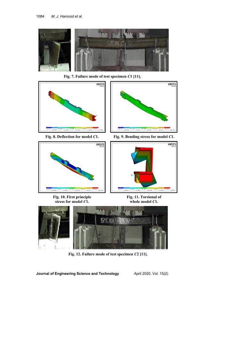
The failure mode of the tested specimen C1 is shown in Fig. 7, while the deflection
manner for the model of C1 is shown in Fig. 8, in which, the maximum applied
load is 65 kN with a deflection at this load reaching 34.88 mm. Figure 9 represents
the bending stress at the compression and tension along with the model. Figure 10
shows the variations of the principle stress (σ1) as the maximum first principle
stress in the plane of zero shear stress. Figure 11 shows the side view of the model
that represents the lateral-torsional buckling (LTB) mode of failure for the control
specimen, which has an opened and unsymmetrical cross-section with small or no
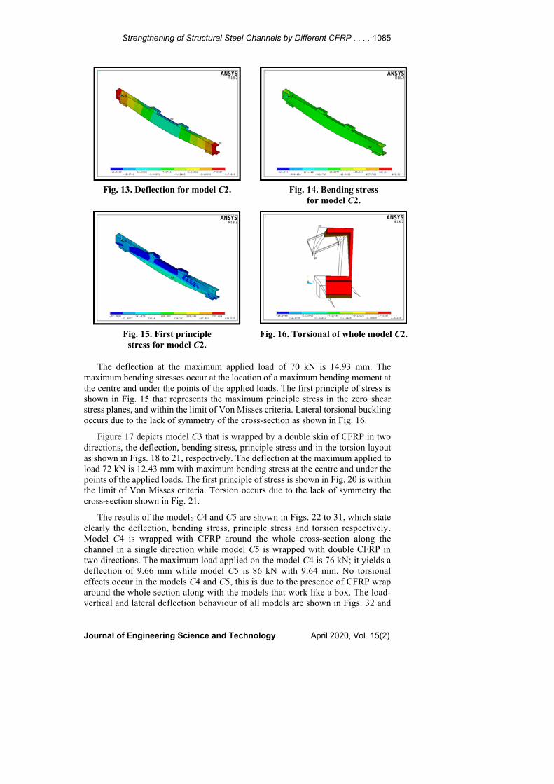
torsional resistance against twisting. Figure 12 depicts model C2 that is wrapped
by a single CFRP in one direction and only at the skin, the deflection, bending
stress, principle stress and torsion layout as shown in Figs. 13 to 16, respectively.
1084 M. J. Hamood et al.
Journal of Engineering Science and Technology April 2020, Vol. 15(2)
Fig. 7. Failure mode of test specimen C1 [11].
Fig. 8. Deflection for model C1. Fig. 9. Bending stress for model C1.
Fig. 10. First principle
stress for model C1.
Fig. 11. Torsional of
whole model C1.
Fig. 12. Failure mode of test specimen C2 [11].
Strengthening of Structural Steel Channels by Different CFRP . . . . 1085
Journal of Engineering Science and Technology April 2020, Vol. 15(2)
Fig. 13. Deflection for model C2. Fig. 14. Bending stress
for model C2.
Fig. 15. First principle
stress for model C2.
Fig. 16. Torsional of whole model C2.
The deflection at the maximum applied load of 70 kN is 14.93 mm. The
maximum bending stresses occur at the location of a maximum bending moment at
the centre and under the points of the applied loads. The first principle of stress is
shown in Fig. 15 that represents the maximum principle stress in the zero shear
stress planes, and within the limit of Von Misses criteria. Lateral torsional buckling
occurs due to the lack of symmetry of the cross-section as shown in Fig. 16.
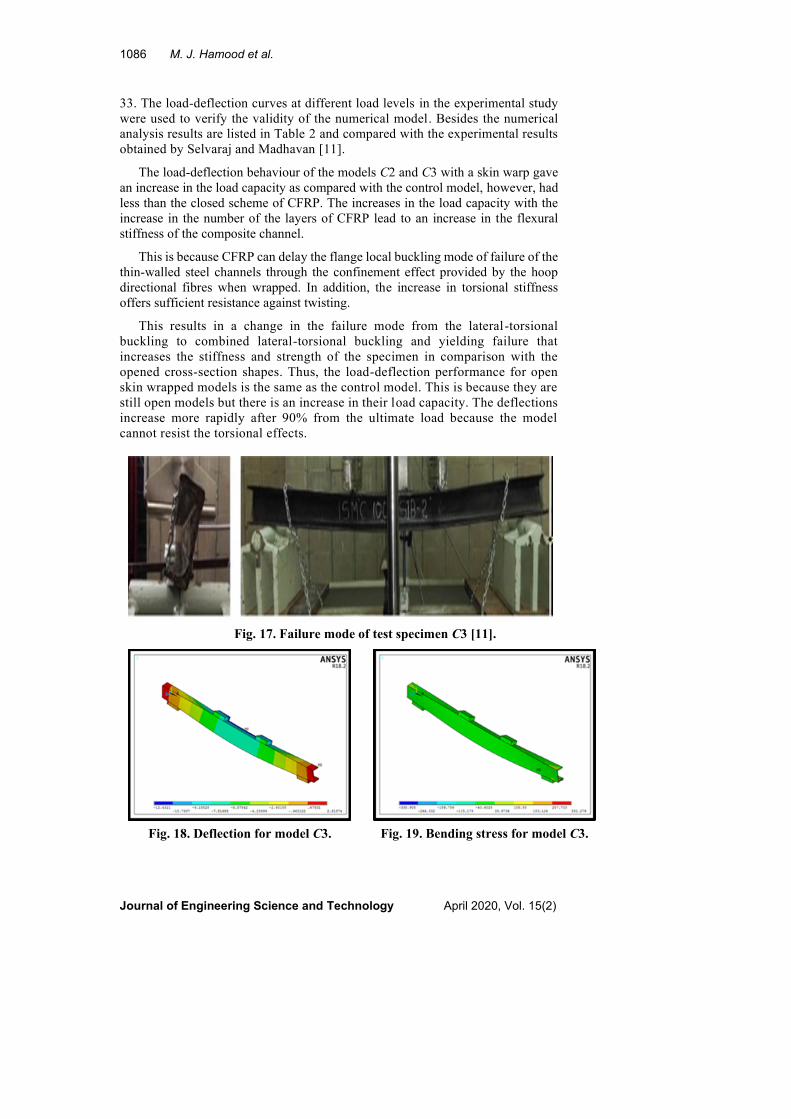
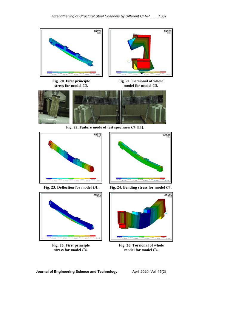
Figure 17 depicts model C3 that is wrapped by a double skin of CFRP in two
directions, the deflection, bending stress, principle stress and in the torsion layout
as shown in Figs. 18 to 21, respectively. The deflection at the maximum applied to
load 72 kN is 12.43 mm with maximum bending stress at the centre and under the
points of the applied loads. The first principle of stress is shown in Fig. 20 is within
the limit of Von Misses criteria. Torsion occurs due to the lack of symmetry the
cross-section shown in Fig. 21.
The results of the models C4 and C5 are shown in Figs. 22 to 31, which state
clearly the deflection, bending stress, principle stress and torsion respectively.
Model C4 is wrapped with CFRP around the whole cross-section along the
channel in a single direction while model C5 is wrapped with double CFRP in
two directions. The maximum load applied on the model C4 is 76 kN; it yields a
deflection of 9.66 mm while model C5 is 86 kN with 9.64 mm. No torsional
effects occur in the models C4 and C5, this is due to the presence of CFRP wrap
around the whole section along with the models that work like a box. The load-
vertical and lateral deflection behaviour of all models are shown in Figs. 32 and
1086 M. J. Hamood et al.
Journal of Engineering Science and Technology April 2020, Vol. 15(2)
33. The load-deflection curves at different load levels in the experimental study
were used to verify the validity of the numerical model. Besides the numerical
analysis results are listed in Table 2 and compared with the experimental results
obtained by Selvaraj and Madhavan [11].
The load-deflection behaviour of the models C2 and C3 with a skin warp gave
an increase in the load capacity as compared with the control model, however, had
less than the closed scheme of CFRP. The increases in the load capacity with the
increase in the number of the layers of CFRP lead to an increase in the flexural
stiffness of the composite channel.
This is because CFRP can delay the flange local buckling mode of failure of the
thin-walled steel channels through the confinement effect provided by the hoop
directional fibres when wrapped. In addition, the increase in torsional stiffness
offers sufficient resistance against twisting.
This results in a change in the failure mode from the lateral-torsional
buckling to combined lateral-torsional buckling and yielding failure that
increases the stiffness and strength of the specimen in comparison with the
opened cross-section shapes. Thus, the load-deflection performance for open
skin wrapped models is the same as the control model. This is because they are
still open models but there is an increase in their load capacity. The deflections
increase more rapidly after 90% from the ultimate load because the model
cannot resist the torsional effects.
Fig. 17. Failure mode of test specimen C3 [11].
Fig. 18. Deflection for model C3. Fig. 19. Bending stress for model C3.
Strengthening of Structural Steel Channels by Different CFRP . . . . 1087
Journal of Engineering Science and Technology April 2020, Vol. 15(2)
Fig. 20. First principle
stress for model C3.
Fig. 21. Torsional of whole
model for model C3.
Fig. 22. Failure mode of test specimen C4 [11].
Fig. 23. Deflection for model C4. Fig. 24. Bending stress for model C4.
Fig. 25. First principle
stress for model C4.
Fig. 26. Torsional of whole
model for model C4.

1088 M. J. Hamood et al.
Journal of Engineering Science and Technology April 2020, Vol. 15(2)
Fig. 27. Failure mode of test specimen C5 [11].
Fig. 28. Deflection for model C5. Fig. 29. Bending stress for model C5.
Fig. 30. First principle
stress for model C5.
Fig. 31. Torsional of whole
model for model C5.
Fig. 32. Load-vertical
deflection for models.
Fig. 33. Load-lateral
deflection for models.
0
10
20
30
40
50
60
70
80
90
100
0 2 4 6 8 10 12
Load
(kN
)
Lateral deflection (mm)
C1
C2
C3
C4
C5

Strengthening of Structural Steel Channels by Different CFRP . . . . 1089
Journal of Engineering Science and Technology April 2020, Vol. 15(2)
5. Parametric Study
In this paper, the behaviour of CFRP wrapped steel channel sections under loading
was investigated using numerical simulation validated using existing experimental
data. After validating the developed models, a parametric study was conducted to
investigate the influence of the number of CFRP layers on ultimate load, deflection
and buckling behaviours and associated failure modes.
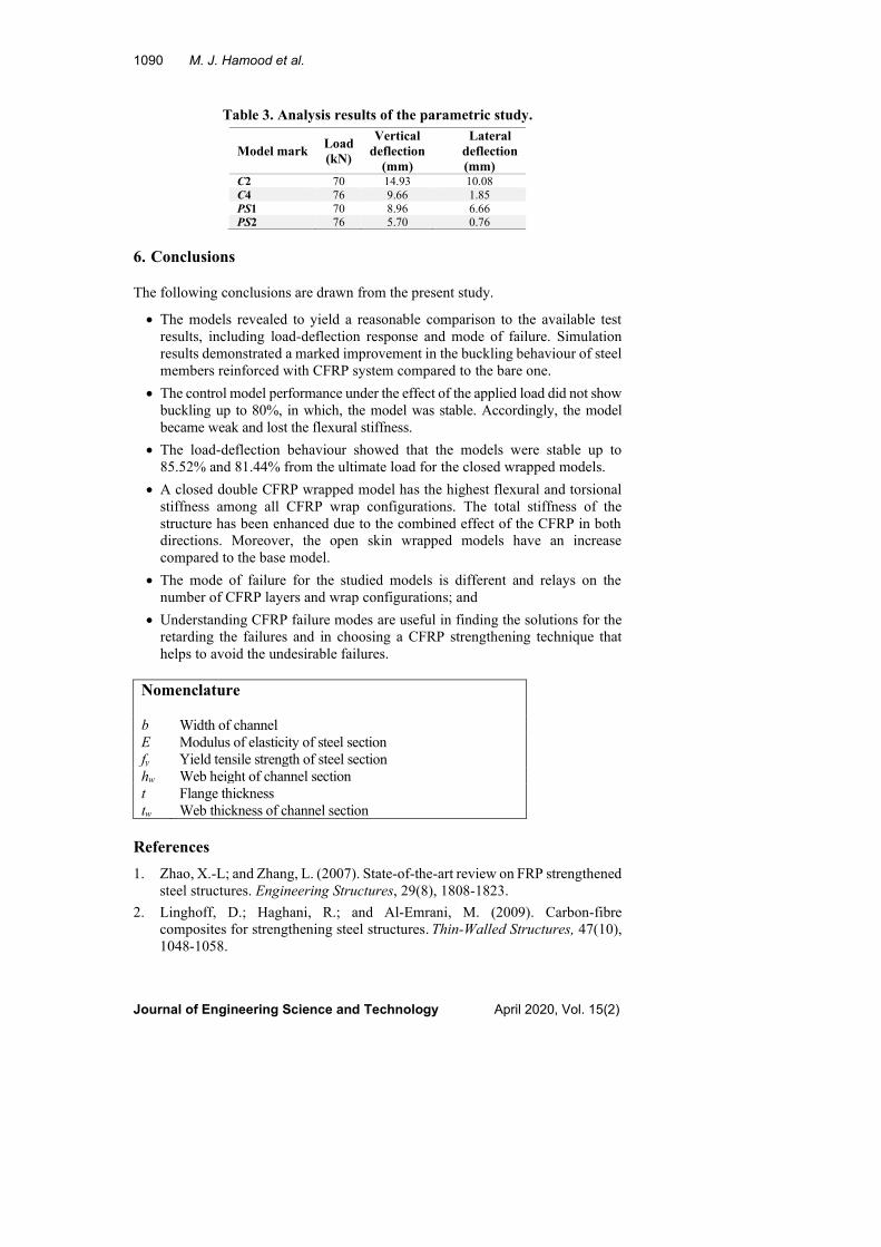
The analysis was performed considering three CFRP layers as full interaction
performance of composite beams under the same load for C2 and C4 models. The
behaviour of vertical and lateral deflections obtained from the analysis are shown
in Figs. 34 and 35. Model results are listed in Table 3. The increase in layers up to
three reduces the vertical and lateral deflections for skin open-wrapped (PS1) as
39.99 and 33.93% and for close-wrapped (PS2) as 40.99 and 58.92% respectively.
Figures 29 and 30 show that the models PS1 and PS2 have the same behaviour of
the models C2 and C4 but differ in vertical deflections and lateral displacements
values at the same applied load due to the increase in the number of CFRP layers
that gave more confinements to the models and increases in load capacity.
Therefore, the performance up to inflexion point is linear and after that, the curve
slop decreases due to the loss in strength because of a decrease in stiffness of the
composite channel. Then, the deflections increase more rapidly after 90% from the
ultimate load because of the model does not resist the torsional effect.
Fig. 34. Load-vertical
deflectionfor parametric study.
Fig. 35. Load-lateral
deflectionfor parametric study.
Table 2. Analysis results of the studied models.
Model
mark Load
(kN)
%
Increase
in load
control
Numerical
vertical
deflection
(mm)
Experimental
vertical
deflection
(mm) [11]
Vertical
deflection
numerical
/experimental
Numerical
lateral
deflection
(mm)
Experimental
lateral
deflection
(mm) [11]
Lateral
deflection
numerical
/experimental
C1 65 --- 34.88 33.00 1.05 10.22 9.75 1.04
C2 70 7.69 14.93 14.50 1.02 10.08 10.60 0.95
C3 72 10.77 12.43 13.00 0.96 8.48 8.75 0.97
C4 76 16.92 9.66 10.50 0.92 1.85 1.90 0.97
C5 86 32.31 9.64 10.25 0.94 0.99 1.10 0.90
Mean 0.98 0.97
Standard division 0.059 0.053
Variance 0.004 0.003
0
10
20
30
40
50
60
70
80
0 2 4 6 8 10 12 14 16
Load
(kN
)
Vertical deflection (mm)
C2
C4
PS1
PS2
0
10
20
30
40
50
60
70
80
0 2 4 6 8 10 12
Load
(kN
)
Lateral deflection (mm)
C2
C4
PS1
PS2
0
10
20
30
40
50
60
70
80
0 2 4 6 8 10 12 14 16
Load
(kN
)
Vertical deflection (mm)
C2
C4
PS1
PS2
0
10
20
30
40
50
60
70
80
0 2 4 6 8 10 12
Load
(kN
)
Lateral deflection (mm)
C2
C4
PS1
PS2
1090 M. J. Hamood et al.
Journal of Engineering Science and Technology April 2020, Vol. 15(2)
Table 3. Analysis results of the parametric study.
Model mark Load
(kN)
Vertical
deflection
(mm)
Lateral
deflection
(mm) C2 70 14.93 10.08
C4 76 9.66 1.85
PS1 70 8.96 6.66 PS2 76 5.70 0.76
6. Conclusions
The following conclusions are drawn from the present study.
• The models revealed to yield a reasonable comparison to the available test
results, including load-deflection response and mode of failure. Simulation
results demonstrated a marked improvement in the buckling behaviour of steel
members reinforced with CFRP system compared to the bare one.
• The control model performance under the effect of the applied load did not show
buckling up to 80%, in which, the model was stable. Accordingly, the model
became weak and lost the flexural stiffness.
• The load-deflection behaviour showed that the models were stable up to
85.52% and 81.44% from the ultimate load for the closed wrapped models.
• A closed double CFRP wrapped model has the highest flexural and torsional
stiffness among all CFRP wrap configurations. The total stiffness of the
structure has been enhanced due to the combined effect of the CFRP in both
directions. Moreover, the open skin wrapped models have an increase
compared to the base model.
• The mode of failure for the studied models is different and relays on the
number of CFRP layers and wrap configurations; and
• Understanding CFRP failure modes are useful in finding the solutions for the
retarding the failures and in choosing a CFRP strengthening technique that
helps to avoid the undesirable failures.
Nomenclature
b Width of channel
E Modulus of elasticity of steel section
fy Yield tensile strength of steel section
hw Web height of channel section
t Flange thickness
tw Web thickness of channel section
References
1. Zhao, X.-L; and Zhang, L. (2007). State-of-the-art review on FRP strengthened
steel structures. Engineering Structures, 29(8), 1808-1823.
2. Linghoff, D.; Haghani, R.; and Al-Emrani, M. (2009). Carbon-fibre
composites for strengthening steel structures. Thin-Walled Structures, 47(10),
1048-1058.

Strengthening of Structural Steel Channels by Different CFRP . . . . 1091
Journal of Engineering Science and Technology April 2020, Vol. 15(2)
3. Haedir, J.; Zhao, X.-L.; Bambach, M.R.; and Grzebieta, R.H. (2010). Analysis
of CFRP externally-reinforced steel CHS tubular beams. Composite
Structures, 92(12), 2992-3001.
4. Elchalakani, M.; and Fernando, D. (2012). Plastic mechanism analysis of
unstiffened steel I-section beams strengthened with CFRP under 3-point
bending. Thin-Walled Structure, 53, 58-71.
5. Teng, J.G.; Yu, T.; and Fernando, D. (2012). Strengthening of steel structures
with fiber reinforced polymer composites. Journal of Constructional Steel
Research, 78, 131-143.
6. Ekiz, E.; and El-Tawil, S. (2008). Restraining steel brace buckling using a
carbon fiber reinforced polymer composite system: experiments and
computational simulation. Journal of Composites for Construction, 12(5),
562-569.
7. Peiris, N.A. (2011). Steel beams strengthened with ultra-high modulus CFRP
laminates. Ph.D. Thesis. College of Engineering, University of Kentucky,
Lexington, Kentucky, United States of America.
8. Kabir, M.H.; Fawzia, S.; and Chan, T.H.T. (2015). Effects of layer orientation
of CFRP strengthened hollow steel members. Gradevinar, 67(5), 441-451.
9. Siwowski, T.W.; and Siwowska, P. (2018). Experimental study on CFRP-
strengthened steel beams. Composites Part B Engineering, 149(15), 12-21.
10. Selvaraj, S.; Madhavan, M.; and Dongre, S.U. (2016). Experimental studies on
strength and stiffness enhancement in CFRP-strengthened structural steel
channel sections under flexure. Journal of Composites for Construction, 20(6),
1-12.
11. Selvaraj, S.; and Madhavan M. (2016). Enhancing the structural performance
of steel channel sections by CFRP strengthening. Thin-Walled Structures, 108,
109-121.
12. Selvaraj, S.; and Madhavan, M. (2017). CFRP strengthened steel beams:
Improvement in failure modes and performance analysis. Structures, 12,
120-131.
13. Chen, X; and Liu Y. (2019). Finite element modeling and simulation with
ANSYS workbench (2nd ed.). Boca Raton, Florida, United States of America:
CRC Press.
14. American Institute of Steel Construction (AISC). (2016). Specification for
structural steel buildings. American National Standard, ANSI/AISC 360-16.
Chicago, Illinois, United States of America.