Strengthening of Steel Stringer Bridges by...
9
54 TRA NSPORTATION RESEARCH R ECORD 1223 Strengthening of Steel Stringer Bridges by Transverse and Longitudinal Stiffening TERRY J. WIPF, F. WAYNE KLAIBER, AND MARCUS J. HALL Adding material to existing steel stringer bridges has been com- monly used as a strengthening method. For simple-span bridges, addition of material can include coverplating, creating composite action with the deck, or increasing transverse stiffness of the exist- ing diaphragm system. For simple-span bridges, these methods may increase live-load ratings by as much as 30 percent, depending on span length. Continuous stringer bridges behave differently when stiffened because of the way stiffening affects the distribution of stress. Because continuous bridges are indeterminate in the transverse direction as well, selective longitudinal stiffening of the stringers and its effect on the whole structural system should be carefully evaluated. In some cases, addition of material to con- tinuous stringers may be detrimental at unstiffened locations. If properly designed, selective longitudinal stiffening can be bene- ficial in strengthening other locations in the bridge by changing th€ stress distribution throughout the bridge. Fatigue-critical details associated with stiffening an existing stringer should be checked, because of possible detrimental effects. According to the Federal Highway Administration, nearly 40 percent of the approximately 600,000 bridges in the United States are currently classified as either geometrically or struc- turally deficient. When the general condition of a bridge is adequate yet structurally deficient, strengthening can often be used as an alternative to replacement or posting. The fea- sibility of bridge strengthening has been discussed in detail by Klaiber et al. (I); they grouped strengthening methods into four categories: (a) addition or modification of a member or support, (b) reduction of dead load, (c) application of external posttensioning, and (d) increased bridge stiffness in either the transverse or the longitudinal direction. Although the last method has been applied in the field, there has been no conclusive evaluation of its effectiveness as a strengthening method. Increased stiffness in the longitudinal direction is achieved by the addition of coverplates, or, if composite action does not already exist, increased stiffness can be achieved by mak- ing the beam composite with the deck in desired locations. Increasing the transverse stiffness of a structure involves increasing the stiffness of existing diaphragms or crossframes or adding diaphragms or crossframes. A previous paper by Dunker et al. (2) briefly addressed transverse and longitudinal stiffening as a means of strength- T. J. Wipf and F. W. Kl aiber, Brid ge Engineering Center, Depa rt- ment of Civil and Constructi on En gi neering, Iowa State Unive rs it y, Ames, Iowa 50011. M. J. Hall , Office of Bridges, Io wa Department of Transportation, Ames, Iowa 50010. ening both determinate and indeterminate steel bridges. Dunker noted that for determinate structures, one strengthening method is the addition of material at locations of overstress. Applying this idea to indeterminate structures has the effect of stiffening the regions where material is added; however, some of the beneficial stiffening effects may be reduced because the stiff- ened region may also attract additional stress. This paper investigated the effects of transverse and longitudinal stiff- ening on distribution of strain at both the stiffened and unstiff- ened locations in determinate and indeterminate bridges. ANALYTICAL MODEL The finite element model shown in Figure 1 used in this inves- tigation was developed on Iowa State University's version of ANSYS (3), a general-purpose program. Two types of ele- ments were employed. Quadrilateral shell elements were used to model the deck, and three-dimensional beam elements were used to model the beams, diaphragms, and curbs. To place the beam's clement at the centroid of the beam , a connector element between the centroid of the deck and the centroid of the beam was needed. A rigid link is typically used to attach the two elements ( 4, 5); however, the rigid link does not account for the transverse flexibility that exists in the steel beam. Because the flexibility in the beam is impor- tant in studying the effects of diaphragms on load distribution, an alternate connector element was needed. A three-dimen- sional beam element, similar to one employed by Dunker (6), was used. The element was given the torsional and flexural moments of inertia of one-half the beam web, thus obtaining the desired flexibility. To ensure that this element did not contribute in carrying any longitudinal bending moment , a moment release connection was employed at the deck. A view of the finite element model for the bridge is shown in Figure 2. Verification of the finite element model developed in this investigation was accomplished by comparing the model results with field test data and results from a previously developed finite element model (using the SAP IV program) of an exist- ing simple-span bridge (7). The bridge was a four-stringer, steel I-beam structure on a SO-ft span with a width of 30 ft. Agreement with strain and deflection data was considered good as shown in Figures 3 and 4. It should be noted that field test data indicated that partial end restraint existed on the bridge, thus the difference between the test dat a and the theoretical curves that assume ideal support conditions. The
-
Upload
truongdiep -
Category
Documents
-
view
216 -
download
1
Transcript of Strengthening of Steel Stringer Bridges by...

54 TRA NSPORTATION RESEARCH R ECORD 1223
Strengthening of Steel Stringer Bridges by Transverse and Longitudinal Stiffening
TERRY J. WIPF, F. WAYNE KLAIBER, AND MARCUS J. HALL
Adding material to existing steel stringer bridges has been commonly used as a strengthening method. For simple-span bridges, addition of material can include coverplating, creating composite action with the deck, or increasing transverse stiffness of the existing diaphragm system. For simple-span bridges, these methods may increase live-load ratings by as much as 30 percent, depending on span length. Continuous stringer bridges behave differently when stiffened because of the way stiffening affects the distribution of stress. Because continuous bridges are indeterminate in the transverse direction as well, selective longitudinal stiffening of the stringers and its effect on the whole structural system should be carefully evaluated. In some cases, addition of material to continuous stringers may be detrimental at unstiffened locations. If properly designed, selective longitudinal stiffening can be beneficial in strengthening other locations in the bridge by changing th€ stress distribution throughout the bridge. Fatigue-critical details associated with stiffening an existing stringer should be checked, because of possible detrimental effects.
According to the Federal Highway Administration, nearly 40 percent of the approximately 600,000 bridges in the United States are currently classified as either geometrically or structurally deficient. When the general condition of a bridge is adequate yet structurally deficient, strengthening can often be used as an alternative to replacement or posting. The feasibility of bridge strengthening has been discussed in detail by Klaiber et al. (I); they grouped strengthening methods into four categories: (a) addition or modification of a member or support, (b) reduction of dead load, (c) application of external posttensioning, and (d) increased bridge stiffness in either the transverse or the longitudinal direction. Although the last method has been applied in the field, there has been no conclusive evaluation of its effectiveness as a strengthening method.
Increased stiffness in the longitudinal direction is achieved by the addition of coverplates, or, if composite action does not already exist, increased stiffness can be achieved by making the beam composite with the deck in desired locations. Increasing the transverse stiffness of a structure involves increasing the stiffness of existing diaphragms or crossframes or adding diaphragms or crossframes.
A previous paper by Dunker et al. (2) briefly addressed transverse and longitudinal stiffening as a means of strength-
T. J . Wipf and F . W. Klaiber, Bridge Engineering Center, Department of Civil and Construction Engineering, Iowa State University, Ames, Iowa 50011. M. J. Hall , Office of Bridges, Iowa Department of Transportation, Ames, Iowa 50010.
ening both determinate and indeterminate steel bridges. Dunker noted that for determinate structures, one strengthening method is the addition of material at locations of overstress . Applying this idea to indeterminate structures has the effect of stiffening the regions where material is added; however, some of the beneficial stiffening effects may be reduced because the stiffened region may also attract additional stress. This paper investigated the effects of transverse and longitudinal stiffening on distribution of strain at both the stiffened and unstiffened locations in determinate and indeterminate bridges .
ANALYTICAL MODEL
The finite element model shown in Figure 1 used in this investigation was developed on Iowa State University's version of ANSYS (3), a general-purpose program. Two types of elements were employed . Quadrilateral shell elements were used to model the deck, and three-dimensional beam elements were used to model the beams, diaphragms, and curbs .
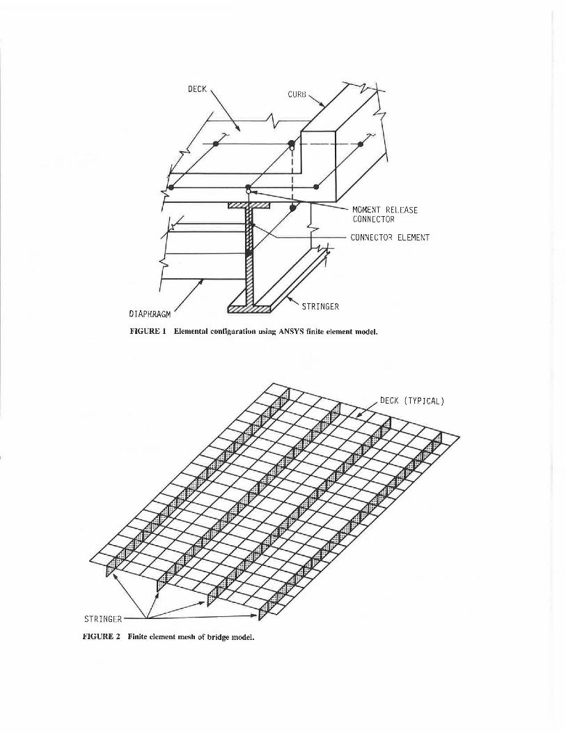
To place the beam's clement at the centroid of the beam , a connector element between the centroid of the deck and the centroid of the beam was needed. A rigid link is typically used to attach the two elements ( 4, 5); however, the rigid link does not account for the transverse flexibility that exists in the steel beam. Because the flexibility in the beam is important in studying the effects of diaphragms on load distribution, an alternate connector element was needed. A three-dimensional beam element, similar to one employed by Dunker (6), was used. The element was given the torsional and flexural moments of inertia of one-half the beam web, thus obtaining the desired flexibility. To ensure that this element did not contribute in carrying any longitudinal bending moment , a moment release connection was employed at the deck. A view of the finite element model for the bridge is shown in Figure 2.
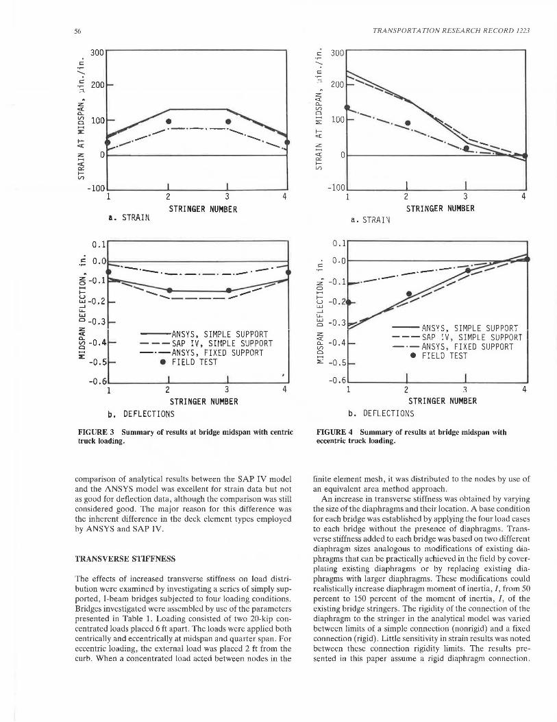
Verification of the finite element model developed in this investigation was accomplished by comparing the model results with field test data and results from a previously developed finite element model (using the SAP IV program) of an existing simple-span bridge (7). The bridge was a four-stringer, steel I-beam structure on a SO-ft span with a width of 30 ft. Agreement with strain and deflection data was considered good as shown in Figures 3 and 4. It should be noted that field test data indicated that partial end restraint existed on the bridge, thus the difference between the test data and the theoretical curves that assume ideal support conditions. The
DIAPHRAGM
MOMENT RELEASE CONNECTOR
'----l---- CONNECTOR ELEMENT
STRINGER
FIGURE 1 Elemental configuration using ANSYS finite element model.
(TYPICAL)
FIGURE 2 Finite element mesh of bridge model.
56
300
.~ 200 ;::l. . z: c:( a.. ::g 100 ...... ::E
.... c:(
.
0.1
~ -0.1 ..... .... ~ -0.2 _. LL LI.I Cl -0 .3 ~ e; -0 .4 Cl ...... ::E
-0.5
• • .----·-·-·-· ............. . ..-·_,- ...._, ............ .
STRINGER NUMBER a. STRAIN
......:::-.. ........ ---........ ____ _
---ANSYS, SIMPLE SUPPORT - - - SAP IV, SHIPLE SUPPORT -·-ANSYS, FIXED SUPPORT
e FIELD TEST
-o.6 ....... ~~~~-'-~~~~__....._~~~~~ 1 2 3
STRINGER NUMBER b. DEFLECTIONS
4
FIGURE 3 Summary of results at bridge midspan with centric truck loading.
comparison of analytical results between the SAP IV model and the ANSYS model was excellent for strain data but not as good for deflection data, although the comparison was still considered good . The major reason for this difference was the inherent difference in the deck element types employed by ANSYS and SAP IV.
TRANSVERSE STIFFNESS
The effects of increased transverse stiffness on load distribution were examined by investigating a series of simply supported , I-beam bridges subjected to four loading conditions. Bridges investigated were assembled by use of the parameters presented in Table 1. Loading consisted of two 20-kip concentrated loads placed 6 ft apart. The loads were applied both centrically and eccentrically at midspan and quarter span. For eccentric loading, the external load was placed 2 ft from the curb. When a concentrated load acted between nodes in the
TRANSPORTATION RESEARCH RECORD 1223
c 300 .,.... -..... c .,.... ;::l. 200 . z: c:( a.. (/)
Cl 1-1 100 ::;:::
1--c:(
z: 1-1 c:( 0 a: 1--(/)
0. 1
c o. o
. -0. l :z: 0 ....... 1-- -0.2 u w _. LL w -0. 3 Cl
z c:(
-0. 4 a.. (/) Cl ....... ::;::: -0. 5
-0.6
·-.... ·--. . ~ -..::: . ...................
STRINGER NUMBER a. STRArn
1
b.
- .l\NSYS, SIMPLE SUPPORT ---SAP IV, SIMPLE SUPPORT -·-ANSYS, FIXED SUPPORT
e FIELD TEST
2 1 STRINGER NUMBER
DEFL EC TI ONS
FIGURE 4 Summary of results at bridge midspan with eccentric truck loading.
4
finite element mesh, it was distributed to the nodes by use of an equivalent area method approach .
An increase in transverse stiffness was obtained by varying the size of the diaphragms and their location . A base condition for each bridge was established by applying the four load cases to each bridge without the presence of diaphragms. Transverse stiffness added to each bridge was based on two different diaphragm sizes analogous to modifications of existing diaphragms that can be practically achieved in the field by coverplating existing diaphragms or by replacing existing diaphragms with larger diaphragms. These modifications could realistically increase diaphragm moment of inertia,/, from 50 percent to 150 percent of the moment of inertia, /, of the existing bridge stringers . The rigidity of the connection of the diaphragm to the stringer in the analytical model was varied between limits of a simple connection (nonrigid) and a fixed connection (rigid) . Little sensitivity in strain results was noted between these connection rigidity limits. The results presented in this paper assume a rigid diaphragm connection.

Wipf et al. 57
TABLE 1 BRIDGE PARAMETERS INVESTIGATED IN TRANSVERSE STIFFNESS MODEL
Parameters Model Values
Bridge length (ft) 30, 60, 90
Bridge width (ft) 30, 38
Stringer spac i ng (ft) 6 . 5, 9.5
Diaphragm moment of inertia 0, 50, 150 (Percent of stringer moment of inertia)
Diaphragm locat i on (Number of diaphragms equally spaced throughout the bridge)
160
140
120
c:: .,... ....... ~ 100
~
z ~ 80 er: IV')
1 , 2 . 3
--- NO DIAPHRAGMS - - CASE 1
- - CASE 2 - ·-CASE 3 - · • • - CASE 4 · · · · · · ·CASE 5 -- -- CASE 6
40 BRIDGE LENGTH = 30 ft BRIDGE WIDTH ~ 38 ft STRINGER SPACING = 9.5 ft
Sf:.E TABLE 2 DESCRIPTION OF CASES
STRINGER NUMBER
FIGURE 5 Maximum strains at bridge centerline with centric loading.
Position of diaphragms considered were (a) midspan only, (b) third points only, and (c) quarter points.
The distribution of strain at the midspan of each bridge was compared to that of other bridges of the same length, width, and stringer spacing. As an example, the strain distributions for a bridge 30 ft long, 38 ft wide , and with stringer spacing of 9.5 ft are shown in Figure 5 (centric loading) and Figure 6 (eccentric loading). Shown in these figures are the strains at the midspan of each stringer for seven different diaphragm configurations. The bridge with no diaphragms was used as the base condition. The diaphragm sizes and locations for the other six cases are listed in Table 2.
Noteworthy in these figures is the general flattening (a more linear change in strain across the bridge cross section) of the curves in Cases 1 through 6. This flattening, illustrated in both Figures 5 and 6, is expected with increases in transverse stiffness. In all bridges investigated, the maximum strain occurred in the exterior beam because of an eccentrically applied load at midspan. The reduction in strain for this critical loading condition for each bridge is shown in Table 3.
In all but two cases, reductions in maximum strains were achieved, with the largest reduction in strain at 29.7 percent, which occurred in the 90-ft-long, 38-ft-wide bridge with a stringer spacing of 9 .5 ft. The average reduction for all bridges

58
300
250
200
150
TRANSPORTATION RESEARCH RECORD 1223
---NO DIAPHRAGMS ----CASE 1 --CASE 2 ---CASE 3 -···-CASE 4 ······· .. CASE 5 -··-CASE 6
SEE TABLE 2 FOR DESCRIPTION OF CASES
z:: Cl: 100 n:: f-V)
50 ~. BRIDGE LENGTH = 30 ft '-~ BRIDGE WIDTH = 38 ft STRINGER SPACING = 9.5 ft
o~~~==-~=--:..::_~~~~~~~ ··~ ..
STRINGER NUMBER
FIGURE 6 Maximum strains at bridge centerline with eccentric schemes.
TABLE 2 DIAPHRAGM SIZE AND LOCATION FOR BRIDGES ANALYZED IN FIGURES 5 AND 6
Diaphragm Size (Percent of Stringer Moment of
Case 1 50%
Case 2 50%
Case 3 50%
Case 4 150%
Case 5 150%
Case 6 150%
was approximately 10 percent. The following general observations were made:
• Greater reduction in strain occurred in the longer span bridges.
• The most effective transverse strain distribution occurred when diaphragms were located at the one-quarter points. The greatest reduction in stress occurred when a larger number of smaller diaphragms were spaced throughout the bridge. Locating diaphragms at the one-third points produced stress reductions approximately one-third as large as reductions produced by diaphragms at the one-quarter points.
• With all other parameters being equal, greater stress
Diaphragm Location Inertia)
Third points
Midspan only
Quarter points
Third points
Midspan only
Quarter points
reductions occurred in bridges with larger stringer spacing for all configurations of added diaphragms.
• For longer span bridges, the greatest stress reduction occurred in the wider bridges. For the shorter span bridges, the stress reduction was similar for all bridge widths considered.
• The greater the diaphragm stiffness, the greater the stress reduction.
LONGITUDINAL STIFFNESS
The addition of coverplates in continuous stringer bridges affects the transverse stiffness of the whole bridge superstruc-

Wipf et al. 59
TABLE 3 STRAIN REDUCTION IN SIMPLE SPAN EXTERIOR STRINGERS AS A RESULT OF INCREASED TRANSVERSE STIFFENING
Diaphragm Stringer Bridge Size Spacing Width
(Percent of stringer (ft) (ft) moment of inertia)
so 6.S 30
so 9.S 30
so 9.5 38
lSO 6.5 30
lSO 9.5 30
lSO 9.5 30
ture system, although in analysis this effect is usually neglected. The same is true when the stringers are made composite with the deck. If longitudinal stiffening of the superstructure is considered for strengthening an existing bridge, these modifications and their effect on the transverse stiffness should be considered.
The variations in load distribution that resulted from stiffening selected longitudinal regions of a bridge were evaluated by analytically investigating a matrix of three-span, continuous, I-beam bridges. Each bridge consisted of four stringers spaced 8 ft on center with a total bridge width of 28 ft and two different configurations of span length (see Table 4). The six different stiffening schemes investigated are shown in Figure 7. The bold lines in this figure represent the stiffened locations on the beams. Combinations of longitudinal stiffening schemes and bridge lengths were examined with the diaphragm's moment of inertia at 10 percent and stiffened longitudinal moment of inertia at 200 percent that of the unstiffened stringer. This increase in the stringer moment of inertia can be obtained in the field by (a) adding coverplates or (b) creating composite action between the stringer and deck.
Loading of the model bridges consisted of 10-ft-wide lane loads of 640 lb per linear foot. The four loading conditions
Reduction in Strain Bridge (%) Length Diaphragm Location (ft) 1/4 pts. 1/3 pts. mid-span
30 3.2 1.6 0.0 60 13.0 4.2 1. 0 90 24.8 7.1 3.S
30 8.4 4.0 3.2 60 16.8 S.2 4.6 90 25.1 S.8 S.8
30 7.4 3.S 2.7 60 17.2 6.S 7.0 90 24.6 7.2 8.7
30 4.S 4.S 0.0 60 17.2 8.9 2. 1 90 27. 7 12.8 4.3
30 14.3 8.8 6.0 60 25.4 12.1 7.S 90 29.5 12.1 7.2
30 14.3 9.3 5.8 60 23.3 12.6 11. 2 90 29.7 13. 2 11. 3
that produced both maximum negative and maximum positive moments for centric and eccentric positions were investigated. Obviously the maximum negative moment occurred at the first interior support when the first two spans were loaded, and the maximum positive moment occurred when the two exterior spans were loaded.
Base conditions were established by applying the four loading conditions to a bridge containing no longitudinal stiffened sections and having standard diaphragms at the supports and midspans. Modifications to this base condition were then made by increasing the longitudinal stiffness as noted earlier .
Noting that strain reduction will obviously occur at the location where material is added, we concentrated the investigation on evaluating the reduction in the maximum strain at secondary locations in continuous-span bridges when the tiffne s wa increased at a primary location. The econdary
location f the bridge was defined as an y location in the bridge where tiffening was not applied. The e regions will be affected by increased stiffness at other locations because of the indeterminacy of the whole bridge system. For example, when all positive moment regions in a bridge were stiffened, the focus of the investigation was on the reduction in strain in the negative moment regions. For such an example, the critical loading condition occurred when the bridge was loaded to cause

60 TRANSPORTATION RESEARCH RECORD 1223
TABLE 4 STRAIN REDUCTION FOR THREE-SPAN CONTINUOUS STRINGERS AS A RESULT OF INCREASED LONGITUDINAL STIFFENING
Strain Reduction at Pier Loaded for Max. Neg. Mom.
(lo)
Strain Reduction in Span 1 Loaded for Max. Pos. Mom.
(lo)
Scheme Span Centric Eccentric Centric Eccentric No. Lengths Loading Loading Loading Loading
(ft)
1 40-50-40 20.6 21. 3 1. 5 2.81 70-100-70 36.1 34.9 1. 3 3.81
2 40-50-40 4.5 6.5 - 2.9 i.ol
70-100-70 5.7 6.9 2 .11 6.11
3 40-50-40 1.4 16.0 0.7 0.61 70-100-70 4.8 26.3 1. 2 0.7
4 40-50-40 1. 6 3.7 4 . 3 -5.51 70-100-70 4.6 2.2 10.2 -3.61
5 40-50-40 2.5 3.3 -4.2 -0.6 70-100-70 2.2 2.6 0.41 4.51
6 40-50-40 1.8 3.0 1.0 1.4 70-100-70 3.4 4.1 1. 1 1. 3
1 Maximum strain changed location from base condition.
Note: Stiffened section I 200 percent of stringer I. , diaphragm I 10 percent
of stringer I for all cases shown.
maximum negative moment. Schemes 1 and 3 were developed with the primary intention of strengthening the negative moment region. Schemes 2, 4, 5, and 6 were developed to strengthen positive moment regions. All six schemes were analyzed so that the effects of stiffening could be observed in both the primary and secondary regions.
The reductions in maximum strain from the base condition for the six stiffening schemes are illustrated in Table 4. As expected, large reductions in strain appeared in the stiffened regions, and smaller reductions appeared in the unstiffened regions. The most favorable reduction in strain noted at a secondary location was 4.5 percent. For the primary or stiffened regions, reductions of approximately 20 percent were noted. Several unexpected effects were observed from these data. As shown for Scheme 5, when the longer bridges were loaded centrically and eccentrically to cause maximum positive moment, the location of maximum strain in the bridge occurred at a different position than in the base condition. In addition, when the shorter bridge was loaded both centrically and eccentrically to cause maximum positive moment, the point of maximum strain changed and increased in magnitude from that found in the base condition. Because of this unde-
sirable behavior, refinement in the method's application was considered.
A number of additional load cases were therefore considered by modifying the length of the stiffened region in the stringer as well as changing both the longitudinal stiffness of the stringer and transverse stiffness of the bridge.
Positive Moment Region
Scheme 2 was reanalyzed with the stiffened section of the positive moment region extended to cover o/10 of the span length. Two cases were considered: (a) moment of inertia of longitudinal section at 200 percent of the stringer and (b) moment of inertia of the longitudinal section at 300 percent of the stringer. The results of strain reduction in the negative moment region are shown in Table 5. As shown, the strain reductions are not significantly different; however, they did show improvement when compared with the earlier condition illustrated in Table 4. The most favorable condition is shown in Table 5 where the strain reduction from base condition was approximately 10 percent. It should be noted that

Wipf et al.
a. SCHEME 1
[ c. SCHEME 3
e. SCHEME 5
FIGURE 7 Longitudinal stiffening schemes.
the strain reduction in the positive region improved only slightly when the region of coverplating was extended to cover 8/10 of the span.
Negative Moment Region
Scheme 1 was further evaluated by considering increases in moment of inertia of 150 percent and 300 percent of the existing stringer moment of inertia. The results of these cases are also shown in Table 5. The maximum reduction in strain was 2.3 percent for the case of a 300 percent increase in longitudinal inertia; results did not differ significantly from those in Table 4.
Combined Transverse and Longitudinal Stiffening
A brief study employing simultaneous transverse and longitudinal stiffening was performed on the three-span, continuous bridge used in this study. In each case, the diaphragm's moment of inertia was increased to 100 percent that of the stringer.
Table 5 also illustrates results with only the transverse stiffness increased. As shown, when the long bridge was centrically loaded to produce maximum positive moment, an increase in the maximum strain was observed. This can be attributed to the additional moment drawn by the large stiffness at midspan. To compensate for this increase in moment, we added additional longitudinal stiffness by application of two of the earlier stiffening schemes.
The first combination utilized Scheme 3 (with the existing stringer moment of inertia increased 200 percent) and was
61
I I ~ .3lil·4Lt I • L • [ _ Ll,_
b. SCHEME 2
d. SCHEME 4
f. SCHEME 6
loaded to cause maximum positive moment. The results, shown in Table 5, closely resemble the results shown inTable 4 for an increase in transverse stiffness only.
The second combination utilized Scheme 4 (with the existing stringer moment of inertia increased 200 percent) and was loaded to cause maximum negative moment. Results shown in Table 5 reveal that strain reduction greater than 10 percent can be obtained with centric loading. However, eccentric loading produced less favorable results.
Fatigue and Strength
Selectively stiffening existing stringers transversely or longitudinally may have an effect on existing live load stress ranges at critical locations. The corresponding effects on fatigue stresses therefore need to be checked when considering strengthening by these methods.
Transverse stiffening will not increase the flexural strength of a bridge, although it does improve its rating capacity, and may not be desirable if flexural strength is critical. Longitudinal stiffening will increase the flexural strength of an existing stringer if regions of strengthening are at plastic hinge locations.
SUMMARY AND CONCLUSIONS
The usual strategy of adding material at overstressed locations in determinate bridges is an obvious solution for increasing the rating of a bridge. Applying this procedure to indeterminate structures may have a detrimental effect, however. For the bridges investigated, a practical amount of transverse

62 TRANSPORTATION RESEARCH RECORD 1223
TABLE 5 STRAIN REDUCTION FOR THREE-SPAN CONTINUOUS STRINGERS MODIFIED FROM CONDITIONS IN TABLE 4
Longitudinal Stiffening
Scheme No.
2
2
1
Modification of Modification of Stiffened Section Diaphragm (% of Stringer I) (% of Stringer I)
200 10
300 10
150 10
300 10
100 10
200 100
200 100
Strain Reduction at Pier Loaded for ~aximum Negative Moment (%)
Span Lengths (ft)
40-50-40 70-100-70
40-50-40 70-100-70
40-50-40 70-100-70
40-50-40 70-100-70
40-50-40 70-100-70
40-50-40 70-100-70
40-50-40 70-100-70
Centric Loading
4.3 5.7
7.4 9.8
7.3 5.4
11.1 12.7
Eccentric Loading
6.7 7. 7
11. 1 12 . 7
0.2 2.4
2.3 3.5
Strain Reduction in Span 1 Loaded for Maximum Positive
Moment (%)
Centric Loading
0.9 0.7
2.6 2.3
9.3 -2.5
10.4 -4. 2 1
Eccentric Loading
1. 6 2.1
4.11 5.71
1. 51 6.41
1. 21 7 . 5
lMaximum strain changed location from base condition.
2combined transverse and longitudinal stiffening case.
stiffening added to existing bridges can decrease the maximum strains by as much as 30 percent on longer span bridges. Adding longitudinal stiffness to indeterminate structures can decrease maximum strain by 8 to 10 percent. Combining transverse and longitudinal stiffening on continuous stringer bridges did not have a significant beneficial effect on strain reduction when compared to longitudinal stiffening only.
ACKNOWLEDGMENT
This paper is based on research sponsored by the American Association of State Highway and Transportation Officials in cooperation with the Federal Highway Administration.
REFERENCES
l. F. W. Klaiber, K. F. Dunker, T. J. Wipf, and W. W. Sanders, Jr. NCHRP Report 293: Methods of Strengthening Existing High-
way Bridges. TRB, National Research Council, Washington, D.C., 1987, 114 pp.
2. K. F. Dunker, F. W. Klaiber, and W. W. Sanders, Jr. Strengthening of Steel Stringer Bridges by Selective Stiffening. In Transportation Research Record 1118, TRB, National Research Council, Washington, D.C., 1987, pp. 43-48.
3. G. J. DeSalvo and J. A. Swanson. ANSYS-Engineering Analysis System. Swanson Analysis Systems, Inc., Houston, Pa. , June 1985.
4. E. S. DeCastro and C. N. Kostem. Load Distribution in Skewed Beam Slab Highway Bridges. Report 378A.7. Fritz Engineering Laboratory, Lehigh University, Bethlehem, Pa., 1975.
5. W. C. Gustafson and R. N. Wright. Analysis of Skewed Composite Girder Bridges. Journal of the Structural Division, ASCE, Vol. 94, No. ST4, April 1968, pp. 919-941.
6. K. F. Dunker. Strengthening of Simple Span Composite Bridges by Post-Tensioning. Ph.D. dissertation. Iowa State University, Ames, 1985.
7. F. W. Klaiber, D. J. Dedic, K. F. Dunker, and W. W. Sanders, Jr. Strengthening of Existing Single Span Steel Beam and Concrete Deck Bridges. Part I, Final Report. Engineering Research Institute, Iowa State University, Ames, 1983.
Publication of this paper sponsored by Committee on Steel Bridges.