STRENGTHENING OF PETRA SLAB HANGER
31
STRENGTHENING OF PETRA SLAB HANGER Analysis of angle section Bachelor’s thesis Hämeenlinna University Centre, Degree Programme in Construction Engineering Spring semester 2020 Mikhail Stoiko
Transcript of STRENGTHENING OF PETRA SLAB HANGER

STRENGTHENING OF PETRA SLAB HANGER
Analysis of angle section
Bachelor’s thesis
Hämeenlinna University Centre, Degree Programme in Construction Engineering
Spring semester 2020
Mikhail Stoiko

ABSTRACT
Degree Programme in Construction EngineeringHämeenlinna University Centre
Author Mikhail Stoiko Year 2020
Subject Strengthening of PETRA Slab Hanger
Supervisor(s) Cristina Tirteu, Jaakko Yrjölä
ABSTRACT
The purpose of this Bachelor’s thesis was to analyse the behaviour ofPETRA Slab Hanger and to develop a strengthening solution for theproduct. The research was commissioned by Peikko Group as a productdevelopment project.
The major part of the thesis consists of the analysis of PETRA Slab Hanger’sdesign procedure. Based on the described limit states for the design ofPETRA, a strengthening solution, its design procedure and justification ofits relevance were introduced.
As a result, Peikko Group will have a versatile design tool for strengtheningPETRA Slab Hanger.
Keywords L-profile, angle section, slab hanger
Pages 27 pages including appendices 67 pages

CONTENTS
1 INTRODUCTION ........................................................................................................ 1
2 PETRA SLAB HANGER ............................................................................................... 2
2.1 Introduction to PETRA Slab Hanger .................................................................. 22.2 Description of principal structural parts ........................................................... 3
3 METHODOLOGY ....................................................................................................... 3
3.1 Basis of design .................................................................................................. 3
4 GEOMETRY ............................................................................................................... 4
4.1 Effect of side plate geometry on PETRA’s structural behavior .......................... 5
5 STRUCTURAL ACTIONS ............................................................................................. 6
5.1 General ............................................................................................................ 65.2 Load distribution .............................................................................................. 65.3 Load cases ........................................................................................................ 85.4 Response of PETRA on design actions............................................................... 8
6 CROSS-SECTIONAL PROPERTIES ................................................................................ 9
6.1 Section centroid, neutral axis ........................................................................... 96.2 Second moment of area ................................................................................. 106.3 Product moment of area ................................................................................ 106.4 Torsional constant .......................................................................................... 10
7 ANALYSIS................................................................................................................ 11
7.1 Side plate ....................................................................................................... 117.2 Front plate ..................................................................................................... 11
7.2.1 General ............................................................................................... 117.2.2 Torsion................................................................................................ 117.2.3 Global bending .................................................................................... 127.2.4 Local bending ...................................................................................... 12
7.3 Welds ............................................................................................................. 13
8 STRENGTHENING ................................................................................................... 13
8.1 Preface ........................................................................................................... 138.2 Front plate’s failure analysis ........................................................................... 138.3 Solution .......................................................................................................... 148.4 Alternative solutions ...................................................................................... 158.5 Strategy.......................................................................................................... 168.6 Design of strengthening component .............................................................. 178.7 Analysis of strengthened section .................................................................... 20
8.7.1 General ............................................................................................... 208.7.2 Welds ................................................................................................. 218.7.3 Additional points................................................................................. 25

9 CONCLUSION ......................................................................................................... 25
REFERENCES................................................................................................................ 26

1
1 INTRODUCTION
The market is becoming more demanding towards standardized products.Many of those require deep and careful analysis, if the product is desiredto exceed its standard properties. When such a demand is increasing,companies strive to broaden the range of standardized solutions.
When it comes to product development, the key thing is to understand thefeatures of the product, its structural behavior and what the weak pointsare. Next comes ideation, then justification by research and finallyapplication.
The aim of that thesis is to provide a strengthening solution for the PETRASlab Hanger to comply with the demands of the market.

2
2 PETRA SLAB HANGER
Information mentioned within chapters 2-7 is an interpretation of the datapublished at Peikko Group Oy website, Technical manual 09.2016 andinternal design handbook developed by Jan Bujnak (Peikko Group),29.01.2010 and updated by Slavomir Matiasko (Peikko Group),15.06.2015.
2.1 Introduction to PETRA Slab Hanger
PETRA Slab Hanger typically consists of L-shaped front plate weldedtogether with similarly shaped side plates (Figure 1). It is used to supportslabs and make openings in slab floors as shown in Figure 2.
Figure 1. PETRA Slab Hanger (Peikko Group Oy n.d.).
Figure 2. Typical layout of hollow-core floor with PETRA (PeikkoGroup Oy 2016).

3
2.2 Description of principal structural parts
The names of structural parts applied in this document are described inFigure 3 below.
Figure 3. Principal structural parts of the PETRA Slab Hanger
3 METHODOLOGY
3.1 Basis of design
That thesis topic does not cover structural fire design; however, the designof PETRA Slab Hanger complies with the following standards:
1. SFS-EN 1990: Basis of structural design2. SFS-EN 1991-1-1: Actions on structures – Part 1-1: General actions –
Densities, self-weight, imposed loads for buildings3. SFS-EN 1991-1-2: Actions on structures – Part 1-2: General actions –
Actions on structures exposed to fire4. SFS-EN 1992-1-1: Design of concrete structures – Part 1-1: General
rules and rules for buildings5. SFS-EN 1992-1-2: Design of concrete structures – Part 1-2: General
rules – Structural fire design6. SFS-EN 1993-1-1: Design of steel structures – Part 1-1: General rules
and rules for buildings7. SFS-EN 1993-1-2: Design of steel structures – Part 1-2: General rules –
Structural fire design8. SFS-EN 1993-1-8: Design of steel structures – Part 1-8: Design of joints9. EN 1168: Precast concrete products – Hollow core slabs

4
4 GEOMETRY
The geometry of PETRA Slab Hanger depends on the floor layout.The length L1 of the front plate is determined by the width of the flooropening. The height h1 of the front plate corresponds to the depth of thesupported slab, while height h2 of side plates corresponds to the depth ofsupporting slabs (Figure 4).
Figure 4. Principal dimensions of PETRA Slab Hanger
The standardized range of principal dimensions for structural parts, as wellas geometry limitations are available at Peikko Group website.
Peikko Group Oy provides a certain PETRA model range, which defines theproduct’s geometry and resistance based on the place of application. In
5
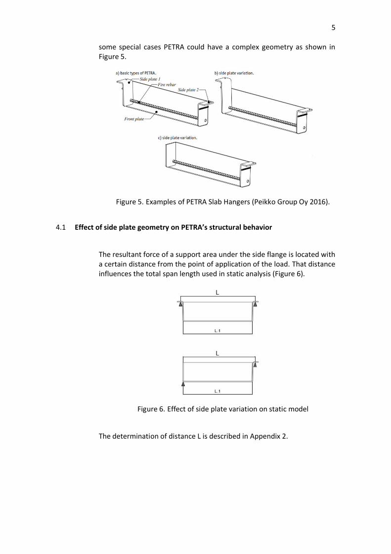
some special cases PETRA could have a complex geometry as shown inFigure 5.
Figure 5. Examples of PETRA Slab Hangers (Peikko Group Oy 2016).
4.1 Effect of side plate geometry on PETRA’s structural behavior
The resultant force of a support area under the side flange is located witha certain distance from the point of application of the load. That distanceinfluences the total span length used in static analysis (Figure 6).
Figure 6. Effect of side plate variation on static model
The determination of distance L is described in Appendix 2.

6
5 STRUCTURAL ACTIONS
5.1 General
The structural actions on PETRA are classified according to EN 1990:
· Permanent actions (G)o the self-weight of structural elements (PETRA slab hanger,
hollow core slab, grouting)o the self-weight of non-structural elements (concrete topping,
floor covering, fixed partition elements etc.)o ring reinforcement
· Variable actions (Q)o imposed loads from buildingso snow loado loads from movable equipment
The different load cases should be combined into the most unfavourableload combination.
gGG× gQQ×+ (1)Where:gG – is the partial safety factor for permanent loads (corresponding tofactor gG j,sup of Table A1.2 of EN 1990/NA – National Annex)gQ – is the partial safety factor for imposed loads (corresponding to factorgQ1 of Table A1.2 of EN 1990/NA – National Annex)
5.2 Load distribution
PETRA slab hanger is assumed to act as a simply supported beam element.Therefore, actions resulting from the self-weight of the supported slab(gHC) and imposed loads (q1, Dg) are modelled as equivalent linear ortriangular reactions on the PETRA slab hanger.
During assembly, PETRA slab hanger is considered to be loaded only by theself-weight of the supported slab. The supported slab acts as a simplysupported beam with PETRA as one of the supports. The load carried byPETRA is determined as follows:
gHC.rgHC L0×
2:= (2)
Where:gHC – is the self-weight of supported slab [kN/m2]L0 – is the length of supported slab

7
After the lateral joints are grouted and hardened, it is possible to considertransverse distribution of loads between hollow-core slabs. This type ofanalysis is allowed by Annex C of the European Standard for hollow-coreslabs (EN 1168) under the condition that the horizontal displacements ofthe hollow-core floor are restricted by the following:- Adjacent structural parts- Friction in supports- Friction in lateral joints- Ring reinforcement- Concrete topping with mesh reinforcement
If at least one of the aforementioned requirements is satisfied, it may beconsidered that PETRA carries only part of the surface load situated withina triangular area.
The effect of imposed surface load on PETRA slab hanger is represented astriangular load with maximum value at mid-span and calculated by thefollowing formula:
q1k3 L1× q1×
2:= D g.k
3 L1× D g×
2:= (3)
Where:q1 – is a variable surface load [kN/m2]Δg – is a permanent surface load [kN/m2]
If concrete topping is cast at the same time as the longitudinal jointsbetween panels, the reaction from topping on the PETRA slab hanger willbe determined in the same way as it is for the self-weight of the hollowcore slab:
gtop.R1gtop L0×
2:= (4)
If concrete topping is cast after the joints between the hollow core slabsare hardened, the reaction on the PETRA slab hanger will be determinedin the same way as it is for the imposed load:
gtop.R23 L1× gtop×
2:= (5)
Where:gtop – is the surface load from concrete topping [kN/m2]

8
5.3 Load cases
The following load cases are considered:
· Surface loads:o Permanent loads: self-weight of supported slab (gHC), self-
weight of concrete topping (gtop), other permanent loads (Dg)o Imposed load (q1)
· Linear loads:o Permanent loads: self-weight of PETRA slab hanger (gPETRA),
self-weight of the grouting (ggrout), self-weight of fixed partitionwall (g.1)
o Imposed loads: reaction from live load acting on partition wall(q2)
· Point loads:o Permanent loads: self-weight of supported column (Gcol)o Imposed load: reaction from live load acting on supported
column (Q3)
The following load combination must be considered for design of PETRAslab hanger acting simultaneously at normal use stage:
· Linear:
gd qd+ gHC.r gpetra+ ggrout+ g1+ gtop.R1+( ) gG× q2gQ×+:= (6)
· Triangular:q1.d Dg.k gtop.R2+( ) gG× q1kgQ×+:= (7)
· Point:Pd GcolgG× Q3gQ×+:= (8)
5.4 Response of PETRA on design actions
Previously described load combinations produce shear force and bendingmoment respective to the load type. The sum of reactions to each loadtype represents the value of total shear force and total bending momentrespectively.
VEdå VEd.lin VEd.tri+ VEd.p+ (9)
Mx.Ed.iå Mx.Ed.lin.i Mx.Ed.tri.i+ Mx.Ed.p.i+ (10)

9
Static formulas used for the determination of the PETRA response on eachload type are presented in Appendix 1.
6 CROSS-SECTIONAL PROPERTIES
To proceed with further analysis, the following cross-sectional propertiesof PETRA’s front plate should be determined:
· Section centroid, neutral axis· Second moment of area· Product moment of area· Torsional constant
The design calculation presented in Appendix 4 implies defining of cross-sectional properties according to Figure 7 below.
6.1 Section centroid, neutral axis
Defining a section centroid is a base of analysis. In order to obtaincoordinates of the centroid of a complex body, the body is split into regularcomponents, which represent common geometric shapes. After commonshapes are defined, the arbitrary coordinate system should be set as areference.
Figure 7. Components and reference coordinate system
When previous steps are fulfilled, the following general formulas shouldbe applied in order to locate centroid of a section:
YSA i yi×
SA i:= X
SAi xi×
SAi:= (11)
Where:

10
Ai – is an area of a componentyi and xi – represent the distance from established reference coordinatesystem to the centroid of a component in y and x direction respectivelyY and X – locate the centroid of a section with respect to establishedcoordinate system
6.2 Second moment of area
Second moment of area represents a measure of efficiency againstbending, thus it should be obtained for further analysis.Data from the previous subchapter allows to determine second momentof area of a section by applying parallel axis theorem:
IY S Iyi Ai dxi2
×+æè
öø:= IX S Ixi Ai dyi
2×+æ
èöø:= (12)
Where:Iyi and Ixi – represent second moment of area relative to the centroid of thecomponentAi – is an area of a componentdxi and dyi – is a distance from the respective centroidal axis of acomponent to the parallel centroidal axis of a sectionIY and IX – represent second moment of area relative to the centroid of thewhole section
6.3 Product moment of area
Product moment of area represents a measure of symmetry of a section.Since PETRA slab hanger consists of unsymmetrical parts, such a valueshould be obtained, in order to proceed with further design.Following the same principles described in subchapter 6.1, productmoment of area should be obtained by:
IXY S Ixyi Ai dxi× dyi×+( ):= (13)Where:Ixyi – is a product moment of area relative to the centroid of the componentAi – is an area of a componentdxi and dyi – is a distance from the respective centroidal axis of acomponent to the parallel centroidal axis of a sectionIXY – represent product moment of area relative to the centroid of thewhole section
6.4 Torsional constant
Torsional constant is used for the evaluation of torsional effect on asection.

11
Calculated and adapted based on the following general formula for thinwalled open sections with uniform thickness:
J13U× t3×:= (14)
Where:U – is a perimeter of median cross-sectiont – is a thickness of a section
7 ANALYSIS
7.1 Side plate
The step-by-step analysis is provided in Appendix 2, section 1.
7.2 Front plate
7.2.1 General
The structural model used to represent the front plate – is a simplysupported beam loaded by the reaction from supported slab.
The front plate has to withstand the following actions:
· Torsion· Global bending· Local bending
The combined effect of those actions is checked in critical points presentedin the section 2.1 of Appendix 2. The state of stress in each point mustcomply with the following condition:
sz.i2 sx.i
2+ sz.isx.i×- 3 txyt.i2×+
fygM0
£ (15)
Where:sz.i – is the normal stress component due to global bendingsx.i – is the normal stress component due to local bendingtxyt – is the shear stress component due to the torsional moment
7.2.2 Torsion
The detailed explanation of section behaviour in torsion is described inAnnex 2, 2.2.
12
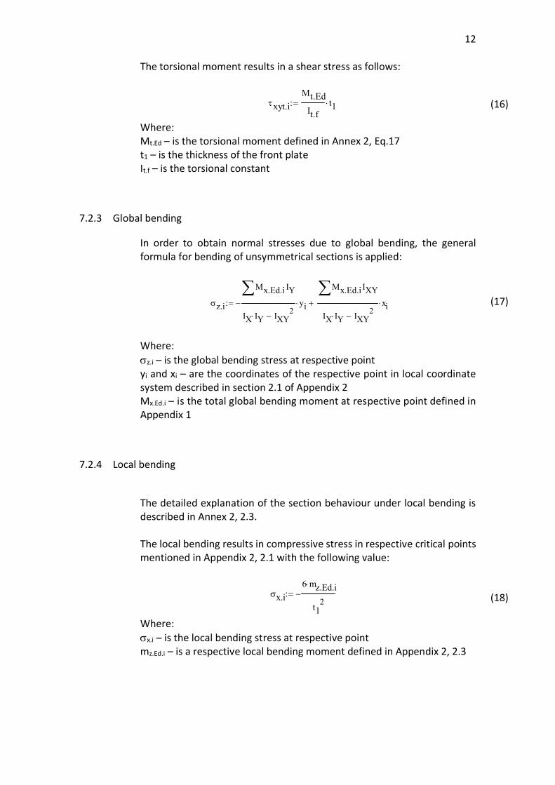
The torsional moment results in a shear stress as follows:
txyt.iMt.EdIt.f
t1×:= (16)
Where:Mt.Ed – is the torsional moment defined in Annex 2, Eq.17t1 – is the thickness of the front plateIt.f – is the torsional constant
7.2.3 Global bending
In order to obtain normal stresses due to global bending, the generalformula for bending of unsymmetrical sections is applied:
sz.i
Mx.Ed.iå IY×
IX IY× IXY2-
- yi×
Mx.Ed.iå IXY×
IX IY× IXY2-
xi×+:= (17)
Where:sz.i – is the global bending stress at respective pointyi and xi – are the coordinates of the respective point in local coordinatesystem described in section 2.1 of Appendix 2Mx.Ed.i – is the total global bending moment at respective point defined inAppendix 1
7.2.4 Local bending
The detailed explanation of the section behaviour under local bending isdescribed in Annex 2, 2.3.
The local bending results in compressive stress in respective critical pointsmentioned in Appendix 2, 2.1 with the following value:
sx.i6 mz.Ed.i×
t12
-:= (18)
Where:sx.i – is the local bending stress at respective pointmz.Ed.i – is a respective local bending moment defined in Appendix 2, 2.3

13
7.3 Welds
The step-by-step design procedure is described in Appendix 2, 2.4.
8 STRENGTHENING
8.1 Preface
In order to develop a strengthening solution for a product, an engineershould understand how the product behaves and what the weak pointsare. The governing limit states described in the previous chapter are:
· Failure of side plate flanges and compression failure of supportingslabs
· Welds failure
· Front plate failure
The side flange failure is a rare case, as well as compression resistancefailure of the supporting slab. However, Peikko Group has a solution forthat case: increased width of side flange L2 benefits both side flangeresistance and compression resistance of the slab by increasing loadingspread.
The welds also have a solution in case of insufficient capacity. Theresistance could be positively affected by increasing welds’ effective lengthand throat thickness.
The front plate appears to be the only component of PETRA which had nostandardized strengthening solution before. Thus, the whole chapter isconcentrated on strengthening of the front plate.
8.2 Front plate’s failure analysis
Based on the information mentioned in chapter 7.2 it is wise to highlightthat, theoretically, there are three possible governing components thatcould result into failure:
· Stress due to global bending
· Stress due to local bending
· Stress due to torsion

14
The behavior of the front plate under global bending depends on itssectional properties, length and intensity of the load. That means thatglobal bending stress is the governing component for long profiles andprofiles with the minimum height.
However, local bending stress could rarely be the governing component, itis likely to occur with short profiles having high global bending resistance.Other than that, the profile must be heavily loaded in order to fail.
The torsional stress cannot be the governing component. Its impact isdescribed in Appendix 2, 2.2.
In practice, most of the studied cases show that failure occurs in the middleof the section due to the global bending stress component.
8.3 Solution
The ideation based on the failure mode analysis resulted into a certainconcept, which later became a solution. Global bending stiffness appearedto be the most reasonable field to improve. It was decided to develop sucha strengthening solution which could contribute to product’s resistanceand at the same time not to interfere with its functioning.
The solution is presented in Figure 8 below:
Figure 8. Strengthened front plate, side view
It is a standard L-profile welded to the back of the front plate. This type ofsolution allows to contribute to global bending stiffness considerably byincreasing the relevant second moment of area.

15
The principal dimensions for the additional L profile are denoted as shownin Figure 9:
Figure 9. Principal dimensions of additional L profile
In order to make it possible to join front plate with a strengtheningcomponent, the limiting value of h and b were developed as follows:
r1 t1+ h t-£ h1 t1+£ (19)r1 t1+ b t-£ b1 t1+£ (20)
Which mean that web and flange of additional L profile must coversufficient space to be welded to the front plate; however, it should nottake more space than the product itself.
8.4 Alternative solutions
Although the main goal is to introduce a global bending stiffening solution,it is possible to use the same strengthening component also for localbending strengthening by means of welding.
The first alternative option is to consider the flange of additional L-profileto be partially active against local bending. Thus, assuming its contributionto the stiffness against local bending, another weld, effective againstdeveloped stress, must be added.
The first alternative solution is presented in Figure 10 below:
16
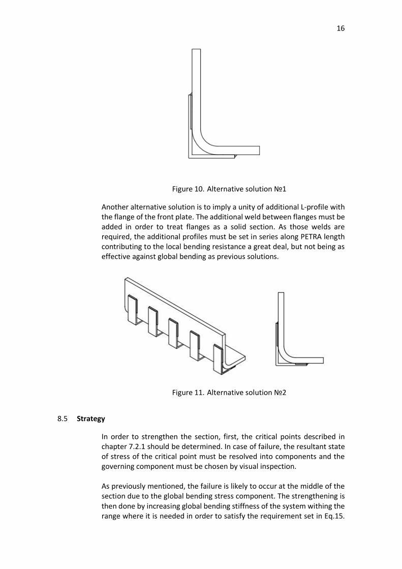
Figure 10. Alternative solution №1
Another alternative solution is to imply a unity of additional L-profile withthe flange of the front plate. The additional weld between flanges must beadded in order to treat flanges as a solid section. As those welds arerequired, the additional profiles must be set in series along PETRA lengthcontributing to the local bending resistance a great deal, but not being aseffective against global bending as previous solutions.
Figure 11. Alternative solution №2
8.5 Strategy
In order to strengthen the section, first, the critical points described inchapter 7.2.1 should be determined. In case of failure, the resultant stateof stress of the critical point must be resolved into components and thegoverning component must be chosen by visual inspection.
As previously mentioned, the failure is likely to occur at the middle of thesection due to the global bending stress component. The strengthening isthen done by increasing global bending stiffness of the system withing therange where it is needed in order to satisfy the requirement set in Eq.15.

17
However, in some rare cases, where local bending stress component mightseem to be dominant, this strategy is still applicable. The additional L-profile’s ledge is also meant to contribute to the stiffness of the systemagainst local bending stress.
If the absolute value of the compressive stress due to local bendingmoment is clearly dominant, then more precise analysis is needed. Since itis the rarest case to happen, it is not covered within this thesis.
8.6 Design of strengthening component
The design procedure starts with the determination of minimum length ofadditional L profile required to cover the global bending failure.The computing power of Mathcad 15 allows to find a certain state of globalbending stress which will satisfy the condition presented in Eq. 15:
sz.p1fy
gM0sz.p1
2 sx.12+ sz.p1sx.1×- 3 txyt.1
2×+ solve sz.p1, ®:=
sz.p1.t max sz.p1( ):=
(21)
Using the general formula for bending of unsymmetrical sectionspresented in Eq. 17, it is possible to obtain a moment which producesaforementioned stress in the section:
Given M 1kNm×:=
sz.p1.tM- IY.f×
IX.f IY.f× IXY.f2-y1×
M IXY.f×
IX.f IY.f× IXY.f2-x1×+
Myield Find M( ):=
(22)
Then, by using static equations presented in Appendix 3, section 1 it ispossible to determine such points xp1 and xp2 along the front plate lengthwhere the sum of moments produced by each load type result intopreviously defined Myield.
Thus, a minimum length of additional L profile is calculated as follows:
Lp.z.min xp2 xp1-:= (23)
In order to determine the minimum required height h of additional Lprofile, which will contribute the most to the global bending stiffness, thestate of stress in front web should be analysed. The following equationallows to determine the minimum global bending stress component

18
required to satisfy the condition presented in Eq. 15 in the middle of thesection:
Given
sz.h1 1N
mm2:=
sz.h12 sx.i
2+ sz.h1sx.i×- 3 txyt.i2×+
fygM0
sz.h.max Find sz.h1( ):=
(24)
The obtained value represents a state of normal stress at a certainlocation. Thus, using the general formula for bending of unsymmetricalsections Eq. 41, it is possible to locate a point where the state of globalbending stress is equal to sz.h.max.
The following equation is used to determine vertical coordinate of a pointlocated at the back face of the front web which will consist of previouslydescribed stress:
Giveny11 1mm:=
Mx.Ed.i- IY×
IX IY× IXY2-y11×
Mx.Ed.i IXY×
IX IY× IXY2-
Xf-×+ sz.h.max
y Find y11( ):=
(25)
Where:Xf – is a horizontal distance from centroid of section to the back face offront web, which coincides with a location of reference coordinate systemillustrated in Figure 2 of Appendix 2y – is a sought vertical coordinate
The obtained vertical coordinate allows to determine the minimumrecommended height of the additional L profile which is defined as follows:
hmin Yf y+:= (26)
The determination of minimum width b of additional L-profile is based onthe idea that state of stress in front flange must satisfy the samerequirement presented in Eq.15, where global bending stress componentsz.b.max and local bending stress component sx.b.max are slightly modified:
sz.b.maxMx.Ed.i- IY×
IX IY× IXY2-
Yf-×Mx.Ed.iIXY×
IX IY× IXY2-
Xf- x11+( )×+:= (27)

19
sx.b.max6 mz.Ed.1× em.ref x11-( )×
t12 em×
-:= (28)
Where:Yf – is a vertical distance from centroid of section to the lower face of frontflange, which coincides with a location of reference coordinate systemillustrated in Figure 2 of Appendix 2x11 – is a certain unknown horizontal coordinate along lower face of frontflangeem.ref – is a reference eccentricity which is defined in Appendix 3, section 1em – is the initial eccentricity described in Appendix 2, 2.3, Eq. 20
The following equation allows to determine such a point x, where frontplate’s ledge is able to resist the combination of stresses:
Given
x11 0mm:=
sz.b.max2 sx.b.max
2+ sz.b.maxsx.b.max×- 3 txyt.i2×+
fygM0
x Find x11( ):=
(29)
Thus, the minimum recommended width b of additional L-profile iscalculated as follows:
bmin x t+:= (30)
Though the minimum recommended values for the strengthening of thesection are obtained, these do not necessarily have to coincide with thedimensions of the additional L-profile. The obtained values are used as ageneral reference for the choice of the strengthening component, which islikely to have different web height and flange width, because of certainstandardized geometry range. Therefore, limiting values for the choice ofL-profile accounting geometry-based limit described in 8.3 are modified asfollows:
max r1 t1+ Yf y+, ( ) h t-£ h1 t1+£ (31)
max r1 t1+ x t+, ( ) b t-£ b1 t1+£ (32)

20
8.7 Analysis of strengthened section
8.7.1 General
Further analysis procedure is based on the same principles describedwithin chapters 5-7 accounting additional L-profile in section properties.
The design calculation presented in Appendix 4 implies defining of cross-sectional properties of a strengthened section according to Figure 12.
Figure 12. Strengthened section components and referencecoordinate system
The state of stress, complying with Eq. 15, is then checked in critical pointsdescribed in Appendix 3, section 2 and additional points illustrated inFigure 13 below:
Figure 13. Additional examination points after strengthening

21
Where global and local bending stresses are defined according toprinciples described in 7.2.3 – 7.2.4 respectively.
8.7.2 Welds
The welds used to connect additional L profile to the front plate aredesigned to withstand maximum global bending stress developed in astrengthened section.
Figure 14. Weld numbering
In order to define the force, which the weld should resist, the state ofglobal bending stress should be defined for the points below (Figure 15).
Figure 15. Points for the state of stress check in strengthened section
Where stresses are obtained by applying a general formula for bending ofasymmetrical sections presented in Eq. 17 accounting for the maximumglobal bending moment defined in Eq. 10 and the following coordinates:

22
xp.h Xf.str- t+:=
yp.h Yf.str- h+:=
xz.max Xf.str- t+:=
yz.max Yf.str-:=
(33)
Where:Xf.str and Yf.str – are the horizontal and vertical coordinates of strengthenedsection obtained by applying principles described in 6.1
Since the additional L-profile might end up covering both compressive andtensile zone, the resultant forces from the global bending stresses areobtained differently for each case.
When L profile is subjected to tensile stresses, the resultant force isobtained as follows:
Fr.T sz.p.hsz.max sz.p.h-
2+
æçè
ö÷ø
ALå×:= (34)
Where:AL – is an area of the additional L profile
When L profile is in compressive and tensile area, two resultant forces aretaken into account:
Fcsz.p.h yp.h×
2t×:= (35)
Ftsz.max2
ALå yp.h t×-æçè
ö÷ø
×:= (36)
Where:Fc – is a resultant force obtained from compressive stressesFt – is a resultant force obtained from tensile stresses
In order to proceed with further analysis, the resultant forces must belocated within the height of the web of additional L-profile. The followingformulas represent distances from the upper surface of additional L-profile’s web to the respective resultant force:
d3 Fp.h× h× Fp.maxh× 4×+
6 Fr.T×:= (37)
dcyp.h3
:=(38)
dt2 Yf.str×
3yp.h+:=
(39)

23
Where:d – is distance to force Fr.T
dc – is distance to force Fc
dt – is distance to force Ft
Aforementioned distances are used to define eccentricities of the forcesto the vertical and horizontal projections of centroid of welds:
e1 d 0.5 h t-( )×-:= (40)
e1.c 0.5 h t-( )× dc-:= (41)
e1.t dt 0.5 h t-( )×-:= (42)
e2 0.5b:= (43)
Thus, forces acting in welds are defined as follows:
Fw.1.T FTFT e1×
h t--
FT e2×
b t-+:= (44)
Fw.1.c.t Fc Ft+Fc e1.c×
h t-+
Fc e2×
b t-+
Ft e1.t×
h t--
Ft e2×
b t-+:= (45)
Fw.2.T FTFT e1×
h t-+
FT e2×
b t--:= (46)
Fw.2.c.t Fc Ft+Fc e1.c×
h t--
Fc e2×
b t--
Ft e1.t×
h t-+
Ft e2×
b t--:= (47)
The proper resultant normal stresses for each weld is chosen upon thecondition presented in the following formulas:
sw.1 3Fw.1.TAw.L
æçè
ö÷ø
2
× sz.p.h 0³if
3Fw.1.c.tAw.L
æçè
ö÷ø
2
× otherwise
:=
(48)
sw.2 3Fw.2.TAw.L
æçè
ö÷ø
2
× sz.p.h 0³if
3Fw.2.c.tAw.L
æçè
ö÷ø
2
× otherwise
:=
(49)

24
Where:sw.1 and sw.2 – are the resultant normal stresses at Weld 1 and Weld 2illustrated in Fig. 14
The area of the weld is defined as follows:
Aw.L aw.L Lp.z.min×:= (50)
The resultant normal stresses should satisfy the following requirement:
sw.1 sw.2fu.Lbw
gM2×£, (51)
When the optimal value for the throat thickness is defined, it is possible toobtain the additional length for the strengthening component which isrequired to activate the weld. The design procedure implies definingresultant forces for each weld (Eq. 44-Eq. 47) complying with the principlesdefined within that chapter, accounting different state of global bendingstress due to Myield (defined in Eq. 22) at points illustrated in Fig. 15.
Ladd.w1.T3 Fw.1.T.y× bw× g M2×
aw.L fu.L×:= (52)
Ladd.w1.t.c3 Fw.1.t.c.y× bw× g M2×
aw.L fu.L×:=
(53)
Ladd.w2.T3 Fw.2.T.y× bw× g M2×
aw.L fu.L×:=
(54)
Ladd.w2.t.c3 Fw.2.t.c.y× bw× g M2×
aw.L fu.L×:=
(55)
The additional length for each weld is defined accounting for condition setin the following formulas:
Ladd.w1 if sz.p.h.y 0³ Ladd.w1.T, Ladd.w1.t.c, ( ):= (56)
Ladd.w2 if sz.p.h.y 0³ Ladd.w2.T, Ladd.w2.t.c, ( ):= (57)
Thus, the total length of the strengthening component is defined asfollows:
Lz.tot Lp.z.min 2max Ladd.w1 Ladd.w2, ( )+:= (58)

25
8.7.3 Additional points
The stress state in additional points is checked to comply with thecondition set in Eq. 15. More detailed design procedure is described inAppendix 3, section 2.
Point p.h is located at the place of contact between additional L profile andback face of front web. It consists of normal stress sz.p.h due to the globalbending moment.
Point p.b is located at the place of contact between additional L profile andback face of front flange. It consists of normal stress sz.p.b due to globalbending and compressive stress sx.p.b due to local bending.
Local bending stress is obtained as follows:
sx.b6 mz.Ed.1× em.b×
t12 em×
-:= (59)
Where:em.b – is a an eccentricity defined in Appendix 3, section 2, Eq. 8
Point L is located at the intersection of the median lines of additional L-profile’s web and flange. It consists of normal stresses from global andlocal bending.
9 CONCLUSION
As a result of the thesis a solution for strengthening PETRA Slab Hangerwas produced for Peikko Group. The developed design calculation allowsto define recommended values of strengthening component as well as todefine section resistance with additional strengthening profile of arbitrarydimensions.

26
REFERENCES
Bujnak, J. & Matiasko, S. (2015) PETRA Slab Hanger Structural design.Internal design handbook, Peikko Group
Lemonis, M.Ε. (2019). Moments of Inertia – Reference TableRetrieved 5 November 2020 fromhttps://calcresource.com/moments-of-inertia-table.html#anchor-16
Peikko Group Oy. (2016). Examples of PETRA Slab Hangers.Retrieved 15 January 2020 fromhttps://d76yt12idvq5b.cloudfront.net/file/dl/i/TTEgOw/sQ2Vx5Go0yIM5XDym7aYlQ/PETRAPeikkoGroup003TMAWeb.pdf
Peikko Group Oy. (2016). PETRA Slab Hanger, Technical manual.Retrieved 5 November 2019 fromhttps://d76yt12idvq5b.cloudfront.net/file/dl/i/TTEgOw/sQ2Vx5Go0yIM5XDym7aYlQ/PETRAPeikkoGroup003TMAWeb.pdf
Peikko Group Oy. (2016). Typical layout of hollow-core floor with PETRA.Retrieved 15 January 2020 fromhttps://d76yt12idvq5b.cloudfront.net/file/dl/i/TTEgOw/sQ2Vx5Go0yIM5XDym7aYlQ/PETRAPeikkoGroup003TMAWeb.pdf
Peikko Group Oy. (n.d). PETRA Slab Hanger.Retrieved 15 January 2020 fromhttps://www.peikko.com/products/product/petra-slab-hanger/
SFS-EN 1168 Precast concrete products. Hollow core slabs. SFS Online.Retrieved 5 November 2019 fromhttps://online.sfs.fi
SFS-EN 1990 Eurocode (2002, 2006). Basis of structural design. SFS Online.Retrieved 5 November 2019 fromhttps://online.sfs.fi
SFS-EN 1991-1-1 Eurocode (2002). Actions on structures. Part 1-1: Generalactions. Densities, self-weight, imposed loads for buildings. SFS Online.Retrieved 5 November 2019 fromhttps://online.sfs.fi
SFS-EN 1992-1-1 Eurocode (2005). Design of concrete structures. Part 1-1:General rules and rules for buildings. SFS Online.Retrieved 5 November 2019 fromhttps://online.sfs.fi

27
SFS-EN 1993-1-1 Eurocode (2005). Design of steel structures. Part 1-1:General rules and rules for buildings. SFS Online.Retrieved 5 November 2019 fromhttps://online.sfs.fi
SFS-EN 1993-1-8 Eurocode (2005). Design of steel structures. Part 1-8:Design of joints. SFS Online.Retrieved 5 November 2019 fromhttps://online.sfs.fi
Tirteu, C. (2018) Statics and strength of materials. Lecture notes 2018,Häme University of Applied Sciences.