Strength of Materials and Failure Theories
38
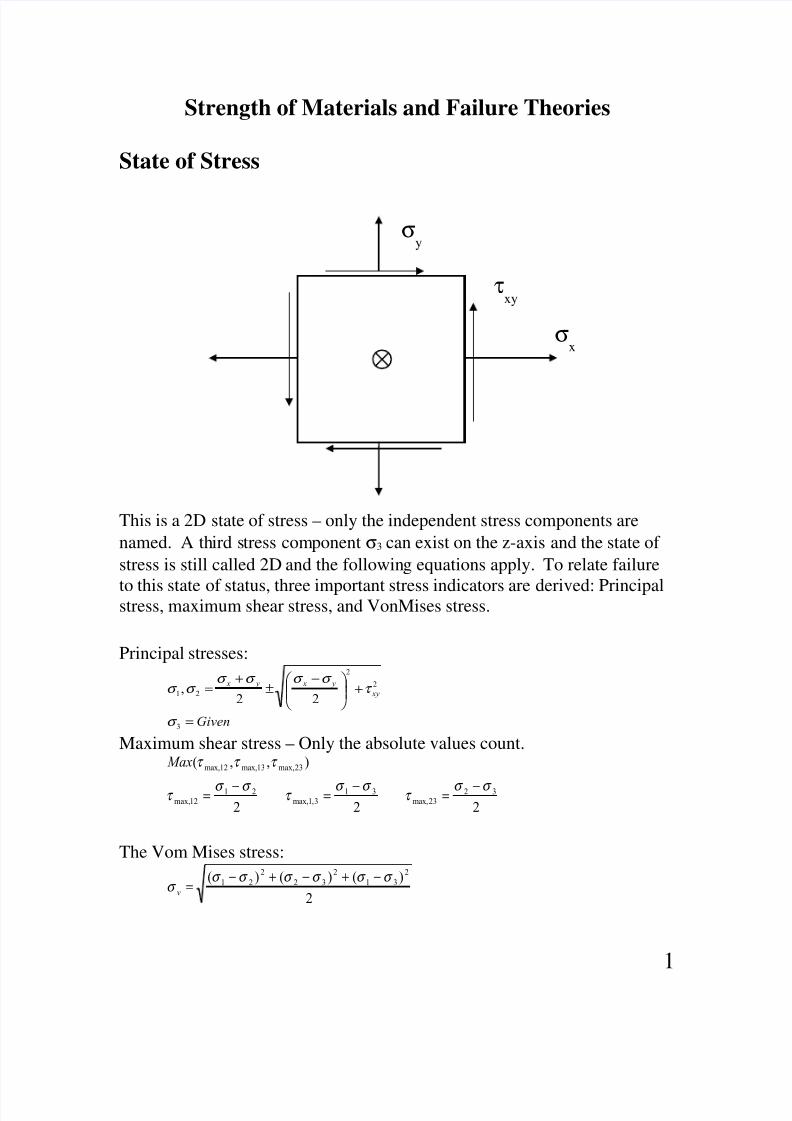
Strength of Materials and Failure Theories State of Stress This is a 2D state of stress – only the independent stress components are named. A th ird s tress component σ 3 can exist on the z-axis and the state of stress is still called 2D and the followin g equations apply. To relate failure to this state of status, three important stress indicators are derived: Principal stress, maximum shear stress, and VonMises stress. Principal stresses: Given xy y x y x = + − ± + = 3 2 2 2 1 2 2 , σ τ σ σ σ σ σ σ Maximum shear stress – Only the absolute values count. 2 2 2 ) , , ( 3 2 23 max, 3 1 3 , 1 max, 2 1 12 max, 23 max, 13 max, 12 max, σ σ τ σ σ τ σ σ τ τ τ τ − = − = − = Max The Vom Mises stress: 2 ) ( ) ( ) ( 2 3 1 2 3 2 2 2 1 σ σ σ σ σ σ σ − + − + − = v σ x τ xy σ y 1
-
Upload
harikumar-andem -
Category
Documents
-
view
238 -
download
0
Transcript of Strength of Materials and Failure Theories
8/12/2019 Strength of Materials and Failure Theories
http://slidepdf.com/reader/full/strength-of-materials-and-failure-theories 1/38
Strength of Materials and Failure Theories
State of Stress
This is a 2D state of stress – only the independent stress components are
named. A third stress component σ3 can exist on the z-axis and the state of
stress is still called 2D and the following equations apply. To relate failure
to this state of status, three important stress indicators are derived: Principalstress, maximum shear stress, and VonMises stress.
Principal stresses:
Given
xy
y x y x
=
+
−±
+=
3
2
2
2122
,
σ
τ
σ σ σ σ
σ σ
Maximum shear stress – Only the absolute values count.
222
),,(
3223max,
313,1max,
2112max,
23max,13max,12max,
σ σ τ σ σ τ σ σ τ
τ τ τ
−=−=−=
Max
The Vom Mises stress:
2
)()()( 2
31
2
32
2
21 σ σ σ σ σ σ σ
−+−+−=
v
σx
τxy
σy
1
8/12/2019 Strength of Materials and Failure Theories
http://slidepdf.com/reader/full/strength-of-materials-and-failure-theories 2/38
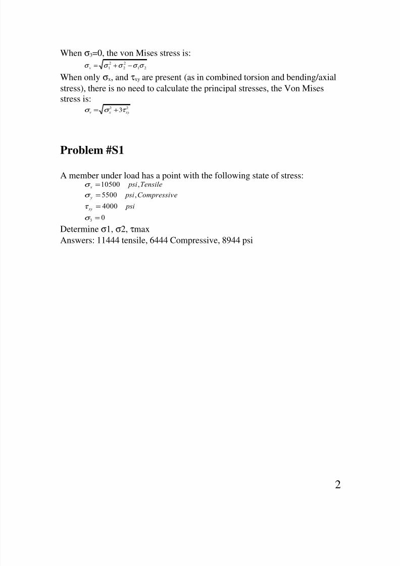
When σ3=0, the von Mises stress is:
21
2
2
2
1 σ σ σ σ σ −+=v
When only σx, and τxy are present (as in combined torsion and bending/axial
stress), there is no need to calculate the principal stresses, the Von Mises
stress is:22 3 xy xv τ σ σ +=
Problem #S1
A member under load has a point with the following state of stress:
0
4000,5500
,10500
3 =
==
=
σ
τ
σ
σ
psieCompressiv psi
Tensile psi
xy
y
x
Determine σ1, σ2, τmax
Answers: 11444 tensile, 6444 Compressive, 8944 psi
2
8/12/2019 Strength of Materials and Failure Theories
http://slidepdf.com/reader/full/strength-of-materials-and-failure-theories 3/38

8/12/2019 Strength of Materials and Failure Theories
http://slidepdf.com/reader/full/strength-of-materials-and-failure-theories 4/38
Bending of straight beams
Bending stress for bending about the Z-axis:
z
z x
I
y M =σ
Bending stress for bending about the Y-axis:
y
y
x I
z M =σ
where Iz and Iy are area moments of inertias about the z and y axes. Use
tables to look up moments of inertia for various cross-sections. The parallel
axis theorem can be used to find moment of inertia w/r a parallel axis:
Problem #S3
x
y
F
z
y
4

8/12/2019 Strength of Materials and Failure Theories
http://slidepdf.com/reader/full/strength-of-materials-and-failure-theories 5/38
The solid circular steel bar with R=2” (diameter 4”) is under two loads as
shown. Determine the normal stress σx at point Q. Point Q is closest to the
observer and the 2000 lb goes into the paper.
Answer: 15600 psi
Problem #S4
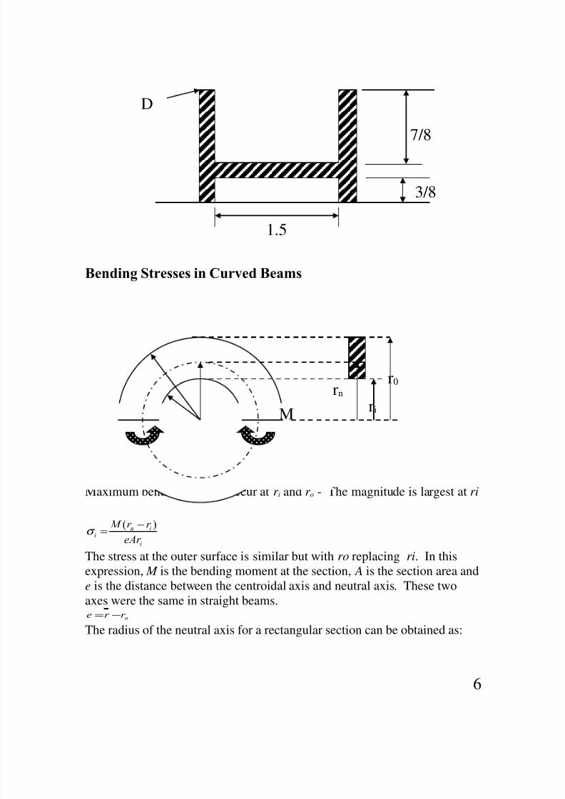
A beam with the cross-section shown is under a bending moment of
FL=Mz=10000 lb-in acting on this cross-section. The thickness of all webs is
0.25 inches.
Determine:
a) The location of the neutral axis (0.667 from bottom)
b) The moment of inertia about the z-axis (0.158 in4)
c) Bending stress at D (52700 psi)
6 ft
4.5 ft4.5 ft
20000 lb
2000 lb
Q
5
8/12/2019 Strength of Materials and Failure Theories
http://slidepdf.com/reader/full/strength-of-materials-and-failure-theories 6/38
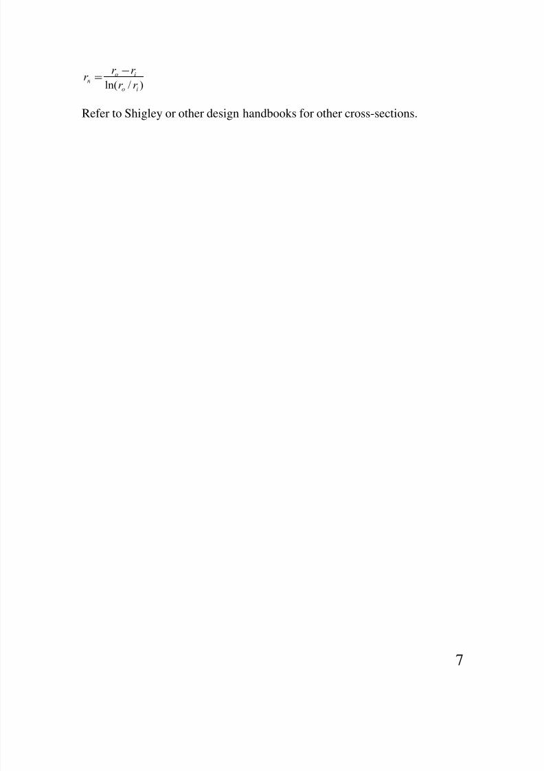
Bending Stresses in Curved Beams
Maximum bending stresses occur at r i and r o - The magnitude is largest at ri
i
ini
eAr
r r M )( −=σ
The stress at the outer surface is similar but with ro replacing ri. In thisexpression, M is the bending moment at the section, A is the section area and
e is the distance between the centroidal axis and neutral axis. These two
axes were the same in straight beams.
nr r e −=
The radius of the neutral axis for a rectangular section can be obtained as:
7/8
3/8
1.5
D
6
rn
ri
r0
M
8/12/2019 Strength of Materials and Failure Theories
http://slidepdf.com/reader/full/strength-of-materials-and-failure-theories 7/38
)/ln( io
ion
r r
r r r
−=
Refer to Shigley or other design handbooks for other cross-sections.
7
8/12/2019 Strength of Materials and Failure Theories
http://slidepdf.com/reader/full/strength-of-materials-and-failure-theories 8/38
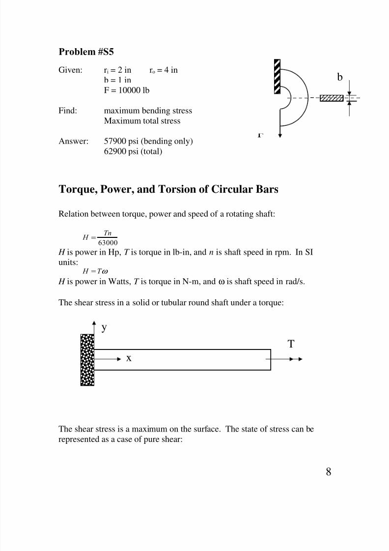
Problem #S5
Given: ri = 2 in ro = 4 in
b = 1 in
F = 10000 lb
Find: maximum bending stress
Maximum total stress
Answer: 57900 psi (bending only)
62900 psi (total)
Torque, Power, and Torsion of Circular Bars
Relation between torque, power and speed of a rotating shaft:
63000
Tn H =
H is power in Hp, T is torque in lb-in, and n is shaft speed in rpm. In SI
units:ω T H =
H is power in Watts, T is torque in N-m, and ω is shaft speed in rad/s.
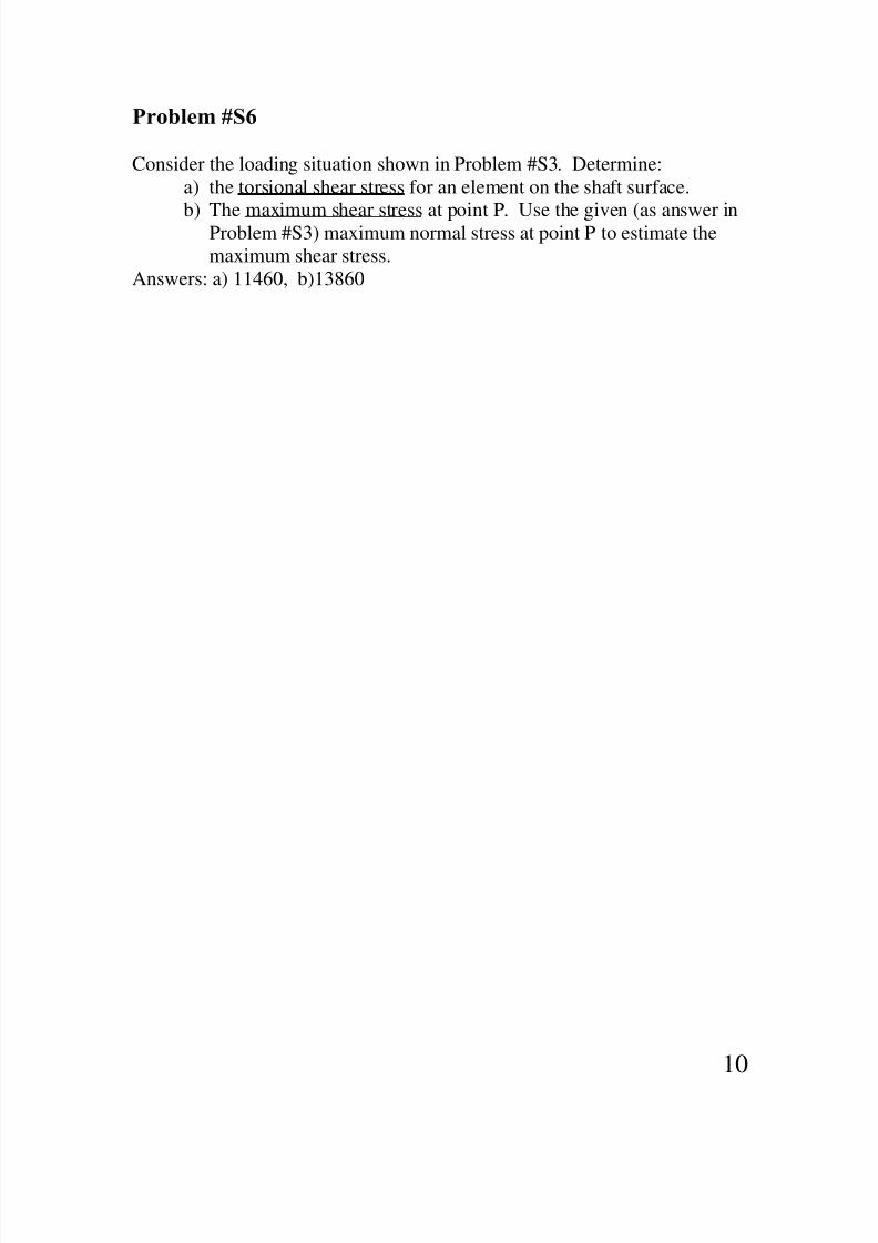
The shear stress in a solid or tubular round shaft under a torque:
The shear stress is a maximum on the surface. The state of stress can be
represented as a case of pure shear:
T
x
y
8
F
b

8/12/2019 Strength of Materials and Failure Theories
http://slidepdf.com/reader/full/strength-of-materials-and-failure-theories 9/38
The shear stress is:
J
Tr =τ
J is the area polar moment of inertia and for a solid (di=0) or hollow section,
)(32
44
io d d J −= π
The Von Mises stress in pure shear is:
xy xyV τ τ σ 33 2==
When the behavior is ductile, yielding occurs when σv reaches the yield
strength of the material. This is based on the distortion energy theory which
is the best predictor of yielding. According to this, yielding occurs when:
ys y xy y xy
xy y yV
S S Or S
S S
===⇒
=⇒=
58.3
1
3
τ τ
τ σ
This predicts that yielding in pure shear occurs when the shear stress reaches
58% of the yield strength of the material. The more conservative maximumshear stress theory predicts yielding to occur at a lower value of shear stress
which is 50% of Sy. The value of shear stress resulting in yielding in a pure
shear situation is known as Sys. In the absence of direct measurements, it is
considered to be 58% of Sy.
The angle of rotation of a shaft under torque
GJ
TL=θ
The angle of rotation is in radians, L is the length of the bar, and G is calledthe shear modulus. The shear modulus can be obtained from the modulus of
elasticity E, and the poisson’s ration ν:
)1(2 ν += E
G
For steels, this value is 11.5*106 psi.
τxy
9
8/12/2019 Strength of Materials and Failure Theories
http://slidepdf.com/reader/full/strength-of-materials-and-failure-theories 10/38
Problem #S6
Consider the loading situation shown in Problem #S3. Determine:
a) the torsional shear stress for an element on the shaft surface.
b) The maximum shear stress at point P. Use the given (as answer inProblem #S3) maximum normal stress at point P to estimate the
maximum shear stress.
Answers: a) 11460, b)13860
10

8/12/2019 Strength of Materials and Failure Theories
http://slidepdf.com/reader/full/strength-of-materials-and-failure-theories 11/38
Deflections, Spring Constants, Load Sharing
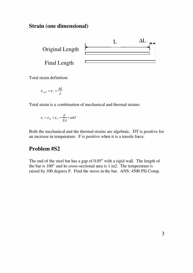
Axial deflection of a bar due to axial loading
The spring constant is:
L
EA K =
Lateral deflection of a beam under bending load
A common cases is shown. The rest can be looked up in deflection tables.
3
48
L
EI K =
For cantilevered beams of length L:
3
3
L
EI K =
Torsional stiffness of a solid or tubular bar is:
L
GJ K t =
The units are pounds per radians.
11
8/12/2019 Strength of Materials and Failure Theories
http://slidepdf.com/reader/full/strength-of-materials-and-failure-theories 12/38
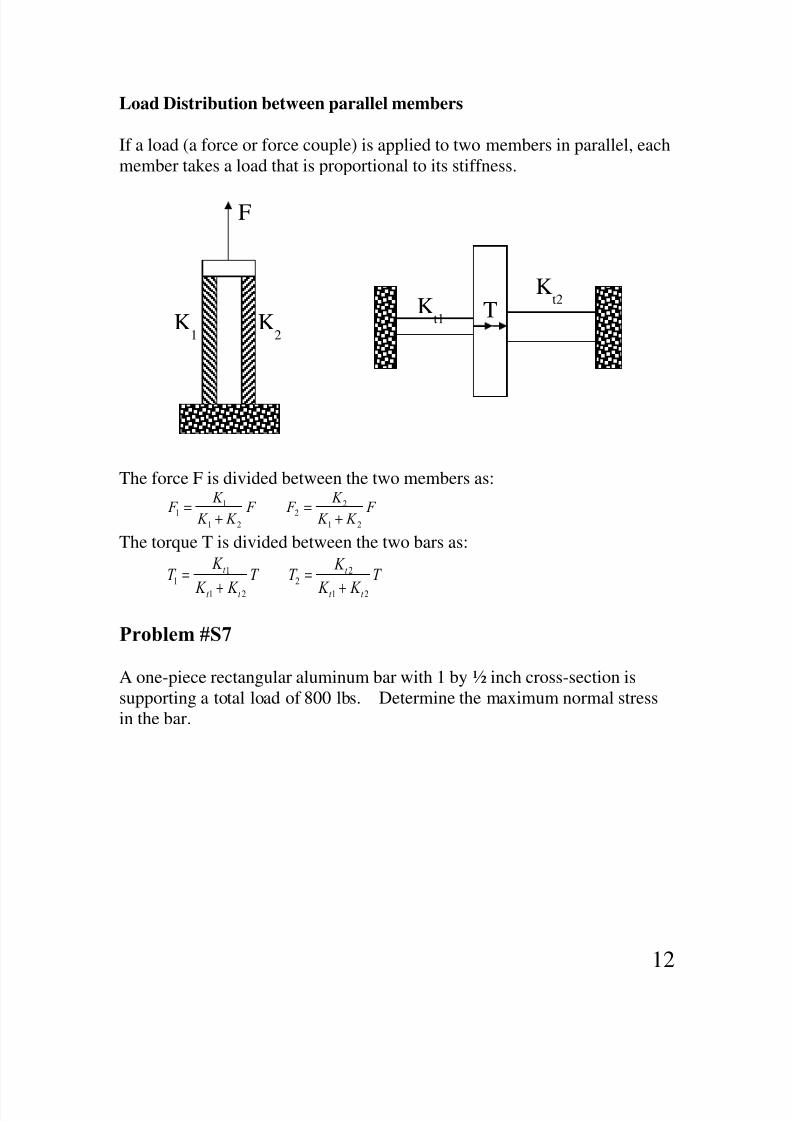
Load Distribution between parallel members
If a load (a force or force couple) is applied to two members in parallel, each
member takes a load that is proportional to its stiffness.
The force F is divided between the two members as:
F K K
K F F
K K
K F
21
22
21
11 +
=+
=
The torque T is divided between the two bars as:
T
K K
K T T
K K
K T
t t
t
t t
t
21
2
2
21
1
1
+
=
+
=
Problem #S7
A one-piece rectangular aluminum bar with 1 by ½ inch cross-section is
supporting a total load of 800 lbs. Determine the maximum normal stress
in the bar.
K2
K1
F
TKt1
Kt2
12

8/12/2019 Strength of Materials and Failure Theories
http://slidepdf.com/reader/full/strength-of-materials-and-failure-theories 13/38
Answer: 960 psi
Problem #S8A solid steel bar with 1” diameter is subjected to 1000 in-lb load as shown.
Determine the reaction torques at the two end supports.
Answer: 600 on the left, 400 on the right.
Direct shear stress in pins
30”
20”
6 ft4 ft
13

8/12/2019 Strength of Materials and Failure Theories
http://slidepdf.com/reader/full/strength-of-materials-and-failure-theories 14/38
Pins in double shear (as in tongue and clevis) is one of the most common
method of axial connection of parts.
The shear stress in the pin is approximately uniformly distributed and is
obtained from:
A
F
2=τ
The clevis is also under tear-out shear stress as shown in the following
figure (top view):
Tear-out shear stress is:
A
F
4=τ
In this formula A=t(Ro-Ri) is approximately and conservatively the area of
the dotted cross-section. Ro and Ri are the outer and inner radii of the clevishole. Note that there are 4 such areas.
t
FF
14

8/12/2019 Strength of Materials and Failure Theories
http://slidepdf.com/reader/full/strength-of-materials-and-failure-theories 15/38
Shear stresses in beams under bending forces
When a beam is under a bending force, its “layers” like to slide on one-
another as a deck of cards would do if bent. Since the beam “layers” can not
slide relative to each other, a shear stress develops within the beam just asshear stresses develop between card faces if they were glued together. This
is shown below. The shear stress in beams is relatively small and can be
ignored for one-piece beams. But for composite beams that are glued,
welded, riveted, bolted, or somehow attached together, this shear stress can
be significant enough to tear off the welding or bolts.
The value of the shear stress depends on the following:
• The shear force V acting on the cross-section of interest. In the above
figure, the shear force is F in all cross-sections. The larger the force,
the larger the stress.
• The width of the beam b at the cross-section. The wider the beam, the
lower the stress.
• The area moment of inertia of the entire cross-section w/r to neutral
axis. The more moment of inertia, the less the stress.• The last parameter is Q which is the Cut Area multiplied by the
distance of the CG of the cut area and the neutral axis.
Important Note: The classical beam theory must be applicable for these
formulas to be valid.
F
τ
15
8/12/2019 Strength of Materials and Failure Theories
http://slidepdf.com/reader/full/strength-of-materials-and-failure-theories 16/38
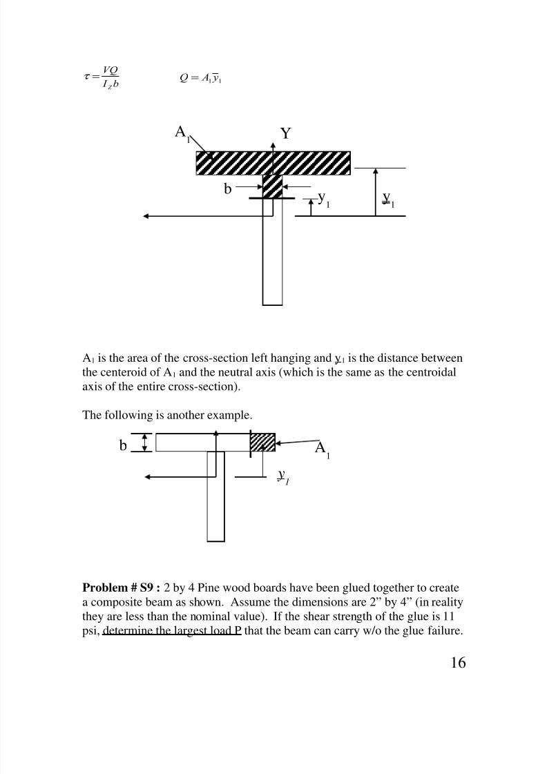
I
V!
"
=τ 11 y A! =
A1 is the area of the cross-section left hanging and y1 is the distance between
the centeroid of A1 and the neutral axis (which is the same as the centroidal
axis of the entire cross-section).
The following is another example.
Problem # S9 : 2 by 4 Pine wood boards have been glued together to create
a composite beam as shown. Assume the dimensions are 2” by 4” (in reality
they are less than the nominal value). If the shear strength of the glue is 11
psi, determine the largest load P that the beam can carry w/o the glue failure.
Y
y1
b
A1
y1
A1
y1
b
16

8/12/2019 Strength of Materials and Failure Theories
http://slidepdf.com/reader/full/strength-of-materials-and-failure-theories 17/38
Assume beam is long enough for the classical beam theory to apply. Do not
consider failure due to bending stresses. Answer: 90.4 lbs
Problem S10: A composite beam is glued as shown. Horizontal members
are 1 by 6 inch and the vertical members are ¼ by 10 inch. Transverse load
at this cross-section is F=250 lbs. Determine the required minimum glue
strength is shear. Answer: 11.8 psi
Shear Center of a C-Channel
P
Cross-section
Z
Y
17
S tw
8/12/2019 Strength of Materials and Failure Theories
http://slidepdf.com/reader/full/strength-of-materials-and-failure-theories 18/38
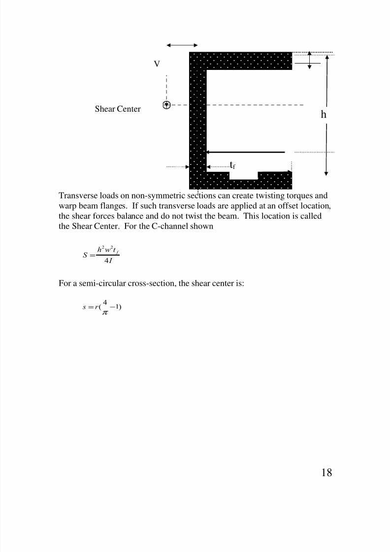
Transverse loads on non-symmetric sections can create twisting torques andwarp beam flanges. If such transverse loads are applied at an offset location,
the shear forces balance and do not twist the beam. This location is called
the Shear Center. For the C-channel shown
I
t #$S
%
4
22
=
For a semi-circular cross-section, the shear center is:
)14
( −=π
r s
18
Shear Center
V
h
tf
8/12/2019 Strength of Materials and Failure Theories
http://slidepdf.com/reader/full/strength-of-materials-and-failure-theories 19/38
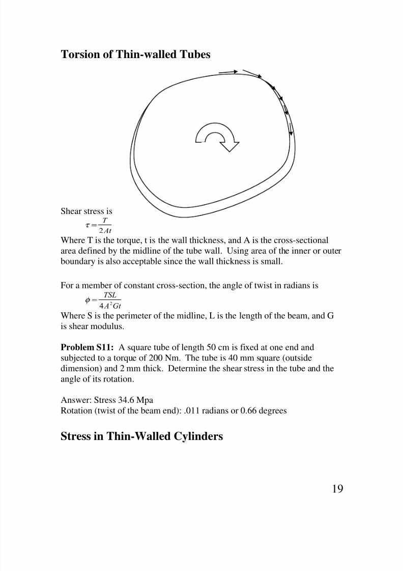
Torsion of Thin-walled Tubes
Shear stress is
At
T
2=τ
Where T is the torque, t is the wall thickness, and A is the cross-sectional
area defined by the midline of the tube wall. Using area of the inner or outer
boundary is also acceptable since the wall thickness is small.
For a member of constant cross-section, the angle of twist in radians is
Gt A
TSL24=φ
Where S is the perimeter of the midline, L is the length of the beam, and G
is shear modulus.
Problem S11: A square tube of length 50 cm is fixed at one end and
subjected to a torque of 200 Nm. The tube is 40 mm square (outside
dimension) and 2 mm thick. Determine the shear stress in the tube and the
angle of its rotation.
Answer: Stress 34.6 MpaRotation (twist of the beam end): .011 radians or 0.66 degrees
Stress in Thin-Walled Cylinders
19

8/12/2019 Strength of Materials and Failure Theories
http://slidepdf.com/reader/full/strength-of-materials-and-failure-theories 20/38
If the thickness t is less than 1/20th of the average radius of the pressure
vessel, the stresses can be closely approximated using the following simple
formulas. The critical stress point in pressure vessels is always on the inner
surface (why?)
The tangential or hoop stress is:
t
&d it
2=σ
The axial stress is:
t
&d ia
4=σ
The radial stress on the inner surface (shown as a circle on the element) is P
which is ignored as it is much smaller than the hoop stress.
Stresses in Thick-walled Cylinders
In thick-walled cylinders the tangential and radial stresses vary
exponentially with respect to the radial location within the cylinder and if
the cylinder is closed the axial stress would be a constant. All the three
stresses are principal stresses – they occur on surfaces on which shearstresses are zero. The critical stress point is on the inner surface.
P
σt
σa
20

8/12/2019 Strength of Materials and Failure Theories
http://slidepdf.com/reader/full/strength-of-materials-and-failure-theories 21/38
The tangential stress:
22
2
2222
io
io
oiooii
t
r r
r
& & r r r & r &
−
−
−−=σ
The radial stress is:
22
2
2222
io
io
oiooii
r r r
r
& & r r r & r &
−
−+−
=σ
When the external pressure is zero, the stresses on the inner surface are:
22
22 )(
io
oii
t
r r
r r &
−+=σ
i
io
oiir &
r r
r r & −=
−−
=22
22 )(σ
When the ends are closed, the external pressure is often zero and the axial
stress is
22
2
io
ii
a
r r
r &
−=σ
Problem #S12: A steel cylinder with a yield strength of 57 ksi is under
external pressure only. The dimensions are:ID=1.25” and OD=1.75”. If the
Po
Pi
σr
σt
21

8/12/2019 Strength of Materials and Failure Theories
http://slidepdf.com/reader/full/strength-of-materials-and-failure-theories 22/38
external pressure is 11200 psi, what is the factor of safety guarding against
yielding. Use the distortion energy theory. Answer: 1.25.
Stresses in rotating rings
A rotating disk develops substantial inertially-caused stresses at high speeds.
The tangential and radial stresses in a disk rotating at ω rad/sec is as follows:
)
3
31)(
8
3(
2
2
22
222r
r
r r r r
oi
oit
ν
ν ν ρω σ
+
+−++
+=
and
))(8
3(
2
2
22222
r r
r r r r
oi
oir −−++= ν
ρω σ
where ρ is the mass density and ν is the Poisson’s ratio.
Problem S13: A disk is rotating at 2069 rpm. The disk’s OD=300 mm and
its ID is 25 mm. The Poisson’s ratio is 0.24 and the disk’s mass density is
3320 kg/m3. Determine the maximum tensile stress in the disk as a result of
rotation. Answer: 0.715 Mpa.
Interface pressure as a result of shrink or press fits
22

8/12/2019 Strength of Materials and Failure Theories
http://slidepdf.com/reader/full/strength-of-materials-and-failure-theories 23/38
When the pressures are very high, shrink-fit cylinders reduce the induced
stresses. When two cylinders with a radial interference of δr are press or
shrink fitted, an interface pressure develops as follows:
The interface pressure for same material cylinders with interface nominal
radius of R and inner and outer radii of ri and ro:
− −−= )(2
))((222
2222
io
ior
r r '
r ' 'r
'
E
&
δ
Problem #S14: A collar is press-fitted on a solid shaft. Bolt parts are made
of steel. The shaft diameter is 40.026 mm and the collar diameter is 40 mm.
The outer diameter of the collar is 80 mm. Find the interface pressure.
Answer: 50 Mpa.
Impact Forces
The equivalent static load created by an object falling and impacting another
object can be very large. Equations of energy in dynamics can be used to
determine such loads. Two common cases involve an object falling from a
distance and a speeding object impacting a structure. In both cases the
damping is assumed to be small.
ri
23

8/12/2019 Strength of Materials and Failure Theories
http://slidepdf.com/reader/full/strength-of-materials-and-failure-theories 24/38
For the falling weight:
( $
F
( (
$) F
st
e
e
++=
++=
δ
211
211
IF h=0, the equivalent load is 2W. For a moving body with a velocity of V
before impact, the equivalent force is:
m) V F e =
Problem #S15: A 1000 lb weight drops a distance of 1-in on a platform
supported by a 1 in2 steel bar of length 12 inches. What is the theoretical
tensile stress that would develops in the bar. Answer: 70.7 ksi.
h
w
k w
v
24

8/12/2019 Strength of Materials and Failure Theories
http://slidepdf.com/reader/full/strength-of-materials-and-failure-theories 25/38
Problem #S16: This is the same problem as #S15 but the bar is made up of
two segments. The upper segment has an area of 2 in2. Determine the
maximum theoretical stress developing in the bar as the result of the weight
dropping on the platform. Answer: 81.6 ksi.
1000
12”
# S15
1000
6”
# S16
6”
25

8/12/2019 Strength of Materials and Failure Theories
http://slidepdf.com/reader/full/strength-of-materials-and-failure-theories 26/38
Failure of columns under compressive load (Buckling)
A beam under axial compressive load can become unstable and collapse.
This occurs when the beam is long and its internal resistance to bending
moment is insufficient to keep it stable. The internal resistance is a functionarea moment of inertia, I, and the stiffness of the material.
Note that the longer the beam, the more
bending moment is created at the center and
for the beam to remain stable, it needs to be
stiffer or have more resistance area.
For every long beam there is a critical load
beyond which even a tiny nudge would result
is a collapse. This critical load can be foundusing Euler formula.
In shorter columns the critical load may cause
stresses well above the yield strength of the
material before the Euler load is reached. For
such cases, Johnson formula is used which
relates the failure to yielding rather than
instability.
The critical Euler load for a beam that is long enough is:
2
2
L
EI C & *r π
=
C is the end-condition number . The following end-condition numbers
should be used for given cases:
• When both end are free to pivot use C=1. Free to pivot means the end
can rotate but not move in lateral direction. Note that even if the ends
are free to rotate a little, such as in any bearing, this condition is
applicable.
• When one end is fixed (prevented from rotation and lateral
movement) and the other is free, use C= 1/4 .
26
P

8/12/2019 Strength of Materials and Failure Theories
http://slidepdf.com/reader/full/strength-of-materials-and-failure-theories 27/38
• When one end is fixed and the other end can pivot, use C=2 when the
fixed end is truly fixed in concrete. If the fixed end is attached to
structures that might flex under load, use C=1.2 (recommended).
• When both ends are fixed (prevented from rotation and lateral
movement), use C=4. Again, a value of C=1.2 is recommended whenthere is any chance for pivoting.
These conditions are depicted below:
An alternate but common form of the Euler formula uses the “slendernessratio” which is defined as follows:
A
I ) #$ere
)
L 'atio sSlendernes =
=
k is the area radius of gyration of the cross-sections.
Range of validity of the Euler formula
Pivot - Pivot
Fixed - Free
Fixed - Pivot
Fixed - Fixed
27

8/12/2019 Strength of Materials and Failure Theories
http://slidepdf.com/reader/full/strength-of-materials-and-failure-theories 28/38
Experimentation has shown that the Euler formula is a good predictor of
column failure when:
yS
EC
)
L 22π
>=
If the slenderness ratio is less than the value in the RHS of the formula, then
the better predictor of failure is the Johnson formula:
−=
CE )
LS S A & y
y*r
1
2
2
π
Problem #S17: The axial load on a round solid steel bar in compression is
5655 lbs. The material is AISI 1030 HR. Assume the end conditions arepin-pin or pivot-pivot. Determine the factor of safety against failure for the
following two conditions:
a) L=60” and D=diameter=1.5”
b) L=18” and D= 7/8 ”
Answers: a) 3.6 and b) 4.4
28
8/12/2019 Strength of Materials and Failure Theories
http://slidepdf.com/reader/full/strength-of-materials-and-failure-theories 29/38
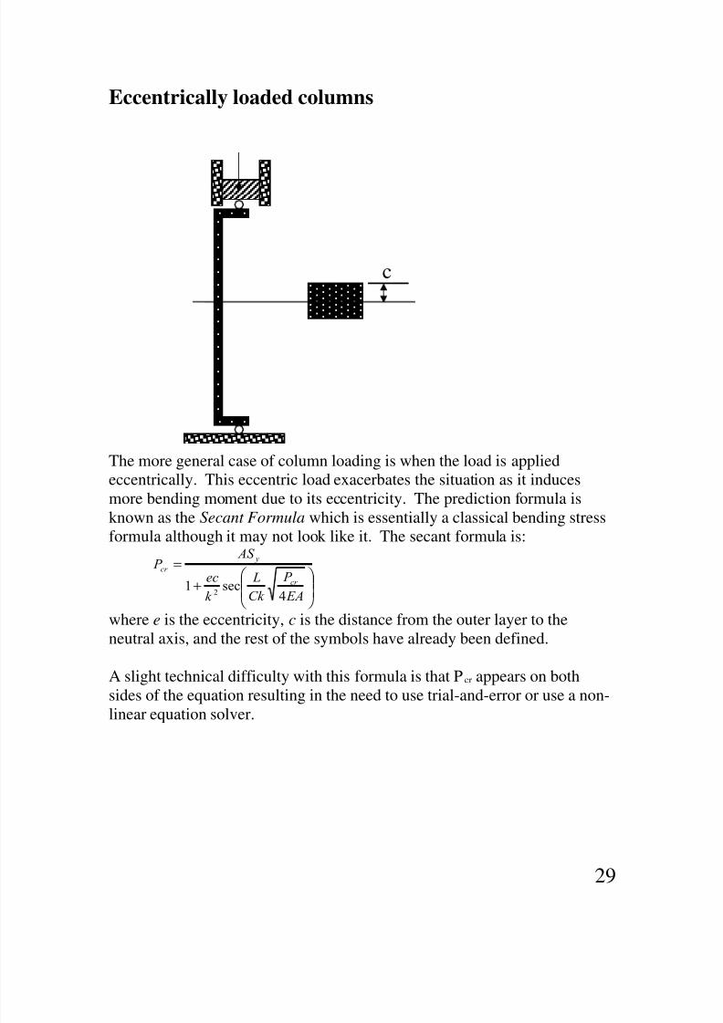
Eccentrically loaded columns
The more general case of column loading is when the load is applied
eccentrically. This eccentric load exacerbates the situation as it induces
more bending moment due to its eccentricity. The prediction formula is
known as the Secant Formula which is essentially a classical bending stress
formula although it may not look like it. The secant formula is:
+
=
EA
&
C)
L
)
e*
AS &
*r
y
*r
4sec1
2
where e is the eccentricity, c is the distance from the outer layer to the
neutral axis, and the rest of the symbols have already been defined.
A slight technical difficulty with this formula is that Pcr appears on both
sides of the equation resulting in the need to use trial-and-error or use a non-
linear equation solver.
c
29

8/12/2019 Strength of Materials and Failure Theories
http://slidepdf.com/reader/full/strength-of-materials-and-failure-theories 30/38
Failure Theories
This section starts with a warning: “Failure” is a tricky term to define.
Failure under load can occur due to excessive elastic deflection or due to
excessive stresses – the same stress for the same material may be consideredexcessive in one type of loading and acceptable in another. Failure
prediction theories due to excessive stresses fall into two classes: Failure
when the loading is static or the number of load cycles is one or quite small,
and failure due to cyclic loading when the number of cycles is large often in
thousands of cycles.
Failure under static load
Parts under static loading may fail due to:
a) Ductile behavior: Failure is due to bulk yielding causing permanent
deformations that is objectionable. These failures may cause noise,
loss of accuracy, excessive vibrations, etc. In machinery, bulk
yielding is the criteria for failure. Note that massive yielding of a
paper clip is not a “failure” as long as it can be bent back to its
original shape. This is not, however, acceptable in machine parts.
b) Brittle behavior: Failure is due to fracture. This occurs when the
material (or conditions) do not allow much yielding such as in grey
cast iron or heavily cold-worked parts. Note that a “ductile” paperclip would fail in a brittle fashion if it is twisted or bent back and forth
sufficiently to make it brittle.
Theories of ductile failure (yielding)
Yielding is a shear stress phenomenon. That means materials yield because
the shear stress on some plane causes the lattice crystals to slide like a deck
of cards. In pure tension or compression, maximum shear stresses occur on
45-degree planes – these stresses cause yielding and not the larger normal
stresses. In fact, in a hydrostatic loading of a cube-shape part where σ1,σ2,σ3
are all the same, maximum shear stress is zero (refer to Page 1) and indeed
the cube-shape part never yields regardless of the pressure it is exposed to!
The best predictor of yielding is the maximum distortion theory (DET).
This theory states that yielding occurs when the Von Mises stress reached
30
8/12/2019 Strength of Materials and Failure Theories
http://slidepdf.com/reader/full/strength-of-materials-and-failure-theories 31/38
the yield strength. The more conservative predictor is the maximum shear
stress theory (MST), which predict yielding to occur when the shear stress
reaches Sy /2. For example in a pure torsion situation, the DET predicts the
yielding to start when τ reaches 58% of Sy. But the MST predicts yielding to
start when τ reaches 50% of Sy.
Note that in static loading and ductile behavior, stress concentrations are
harmless as they only create small localized yielding which do not lead to
any objectionable dimensional changes. Remember that material “yielding”
per se is not harmful to the material.
Problem # S18: A 2” diameter steel bar with Sy=50 ksi is under pure
torsion of a 20,000 in-lb. Find the factor of safety guarding against yielding
based on: a) Distortion energy theory, and b) Max shear stress theory.
Rounded answers: 2.3 and 2.
Theories of brittle failure
There are two types of theories for brittle failure. The classical theories
assume that the material structure is uniform. If the material structure is
non-uniform, such as in many thick-section castings, and that the probability
of large flaws exist, then the theory of fracture mechanics predicts the failure
much more accurately. Many old ship hulls have split in two while the
existing classical theories predicted that they should not. We will only lookat the classical brittle failure theories.
An important point to remember is that brittle material often show much
higher ultimate strength in compression than in tension. The reason is that,
unlike yielding, fracture of brittle materials when loaded in tension is a
normal stress phenomenon. The material fails because eventually normal
tensile stresses fracture or separate the part in the direction normal to the
plane of maximum normal stress (or principal stress – see Page 1). In
compression the story is quite different. When a brittle material is loaded in
compression, the normal stress can not separate the part along the directionnormal to the plane of maximum normal stress. In the absence of separating
normal stresses (tensile stresses), shear stresses would have to do the job and
separate or fracture the material along the direction where the shear stresses
are maximum. In a pure compression, this direction is at 45 degrees to the
plane of loading. Brittle materials, however, are very strong in shear –
31
8/12/2019 Strength of Materials and Failure Theories
http://slidepdf.com/reader/full/strength-of-materials-and-failure-theories 32/38
almost as strong in shear as in tension. The bottom line is that it takes a lot
more compressive normal stress to create a shear stress that is capable of
fracturing a brittle part loaded in compression.
We only discuss these theories for a 2D state of stress – 3D is similar but is
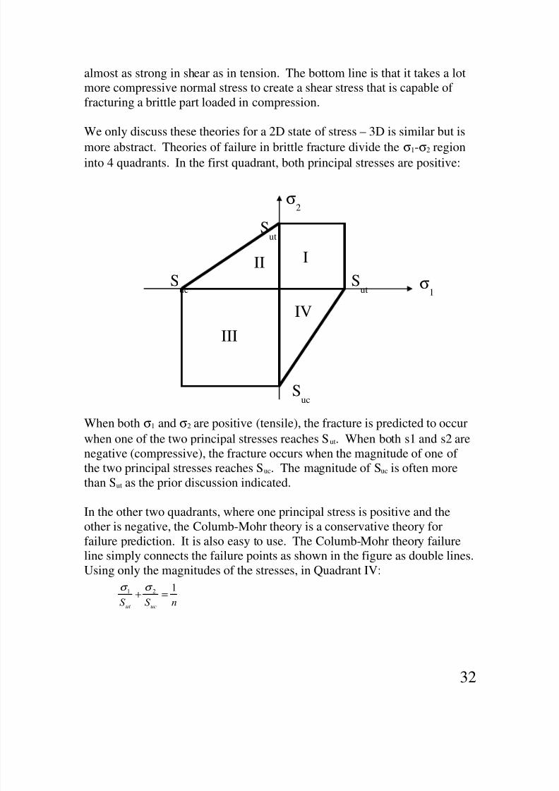
more abstract. Theories of failure in brittle fracture divide the σ1-σ2 region
into 4 quadrants. In the first quadrant, both principal stresses are positive:
When both σ1 and σ2 are positive (tensile), the fracture is predicted to occur
when one of the two principal stresses reaches Sut. When both s1 and s2 are
negative (compressive), the fracture occurs when the magnitude of one of
the two principal stresses reaches Suc. The magnitude of Suc is often more
than Sut as the prior discussion indicated.
In the other two quadrants, where one principal stress is positive and the
other is negative, the Columb-Mohr theory is a conservative theory for
failure prediction. It is also easy to use. The Columb-Mohr theory failure
line simply connects the failure points as shown in the figure as double lines.Using only the magnitudes of the stresses, in Quadrant IV:
σ1
σ2
Sut
SutSuc
Suc
III
III
IV
32
nS S +*+t
121 =+ σ σ
8/12/2019 Strength of Materials and Failure Theories
http://slidepdf.com/reader/full/strength-of-materials-and-failure-theories 33/38
In this formula (σ1,σ2) is the load point (two principal stresses), and n is the
factor of safety associated with that load point. For Quadrant II, switch Sut
and Suc.
Problem #S19: A flywheel made of Grade 30 cast iron has the followingdimensions: ID=6”, OD=10” and thickness=1.5”. What is the speed that
would lead to the flywheel’s fracture? Answer: 13600 rpm
Problem # S20 [Design Challenge Problem]: Design a wheel or blade (like
a rotating ring) that can be spun at very high speeds. The OD of the wheel
or blade is to be 3 inches. Select the material and geometry. Use DET if the
material is ductile. What is the maximum rpm for the blade?
33
8/12/2019 Strength of Materials and Failure Theories
http://slidepdf.com/reader/full/strength-of-materials-and-failure-theories 34/38
Fatigue Failure
Repeated loading can lead to fatigue failure at loads much less than those
leading to static failure. Fatigue failure is sensitive to the magnitude of thestress regardless of how localized and small the stress area is. Therefore,
stress concentrations play an important role in fatigue failure. Note: If the
material bulk itself is full of unseen stress raisers (such as in grey cast iron),
the geometric stress raisers must be ignored. Unless otherwise specified,
this review addresses only the infinite life of steel parts.
Design for infinite life starts with test results of the material in rotating
bending test (known as Moore test). This Moore test stress limit is called
the rotating bending endurance limit, S’n. This is the stress for which no
failure occurs regardless of the number of cycles. In the absence of directexperimental data, this Moore test endurance limit is 50% of the ultimate
stress for steels.
The rotating bending or Moore test endurance limit has to be corrected for
the actual part loading and conditions. This includes corrections for surface
roughness, gradient effect, and size of the part (in Moore test the specimen
are polished, under rotating bending, and are 0.3” in diameter). The result of
these corrections is the endurance limit Sn.
Combined Loading
Fatigue is a yield-related phenomenon – the failure is related to localized
repeated yielding of the material. For that reason, it is no surprise that
fatigue failure prediction correlates with the distortion energy theory (DET).
When the loading is not like bending (or axial), the loading can be combined
into Von Mises stresses and this stress can be analyzed.
34

8/12/2019 Strength of Materials and Failure Theories
http://slidepdf.com/reader/full/strength-of-materials-and-failure-theories 35/38
The index a in the above formula emphasizes that the loading is purelyalternating.
Problem #S21
The steel shaft shown below is under purely alternating torque of 56 N-m.
The torque fluctuates between 56 Nm CW and 56 Nm CCW. Assume
Sut=518 MPa, and the correction factors of 0.9 and 0.78 apply for gradient
and surface finish. [Do not apply what is called a load factor CL]. Also
assume a fatigue stress concentration factor of 1.48 for the shoulder fillets.
Answer: About 2
σa
Sn
Endurance Limit
Von Mises
Stress
20 mm
35

8/12/2019 Strength of Materials and Failure Theories
http://slidepdf.com/reader/full/strength-of-materials-and-failure-theories 36/38
Fluctuating and Steady Loads
When both steady and fluctuating loads are present, the Goodman criterion
is used to determine how much the steady loading affects (reduces) the
endurance limit. To begin the analysis, determine the steady and alternating
Von Mises stresses. These are actual maximum stresses and they do include
the fatigue stress concentration factors. As a result we should be able tocalculate the following:
This designates the load point which plots in the Goodman diagram as
shown below:
Mean Stress
Alternating Stress
36
aV
mV
,
,
σ
σ

8/12/2019 Strength of Materials and Failure Theories
http://slidepdf.com/reader/full/strength-of-materials-and-failure-theories 37/38
To determine the factor of safety guarding against fatigue failure, we must
consider the overload mechanism. If only the steady stress is subject to
increase, the margin of safety is determined by the horizontal load line
shown as it hits the yield strength line. The margin of safety is actually a
little more but conservative application uses the yield line.
If only the alternating stress is subject to increase, the margin of safety is
determined by the vertical load line shown as it hits the Goodman line. If
both the steady and alternating components of stress are subject to increase
as shown, the margin of safety is determined by either the Goodman line or
the yield line.
Sn
Sy
Sy
Su
σv,m
σv,a
Load Point
37

8/12/2019 Strength of Materials and Failure Theories
http://slidepdf.com/reader/full/strength-of-materials-and-failure-theories 38/38