Strength and deformation properties of granite, basalt ...
170
C-l MISCELLANEOUS PAPER C-69-1 STRENGTH AND DEFORMATION PROPERTIES OF GRANITE, BASALT, LIMESTONE AND TUFF AT VARIOUS LOADING RATES by R. L. Stowe grew ¡01 I0S ÉBflns l January 1969 Sponsored by Defense Atomic Support Agency Conducted by U. S. Army Engineer Waterways Experiment Station CORPS OF ENGINEERS Vicksburg, Mississippi THIS DOCUMENT HAS BEEN APPROVED FOR PUBLIC RELEASE AND SALE; ITS DISTRIBUTION IS UNLIMITED
Transcript of Strength and deformation properties of granite, basalt ...

C- lM ISCELLANEOUS PAPER C-69-1
STRENGTH AND DEFORMATION PROPERTIES OF GRANITE, BASALT, LIMESTONE
AND TUFF AT VARIOUS LOADING RATESby
R. L. Stowe
grew¡01 I0SÉBflnsl
January 1969
Sponsored by
Defense Atomic Support Agency
Conducted by
U. S. Army Engineer Waterways Experiment Station
C O R P S O F E N G IN E E R S
Vicksburg, Mississippi
THIS DOCUMENT HAS BEEN APPROVED FOR PUBLIC RELEASE AND SALE; ITS DISTRIBUTION IS UNLIMITED
.'/<* • .'.¡fLIBRARY4
APR 15 1969
Bureau of ReclamationDenver, Colorado
c-1
Destroy this report v¡1
The findings in this report are not to be construed as an o ff ic ia l Department of the Army posit ion, unless so
designated by other authorized documents.
vC*-/$ (K c\
' < y '
MISCELLANEOUS PAPER C-69-1
STRENGTH AND DEFORMATION PROPERTIES OF GRANITE, BASALT, LIMESTONE
AND TUFF AT VARIOUS LOADING RATESby
R. L Stowe
January 1969
Sponsored by
Defense Atomic Support Agency
Conducted by
U. S. Army Engineer Waterways Experiment Station
CORPS O F EN G IN EER SVicksburg, Mississippi
A R M Y -M R C V IC K S B U R G . M IS S .
THIS DOCUMENT HAS BEEN APPROVED FOR PUBLIC RELEASE AND SALE; ITS DISTRIBUTION IS UNLIMITED


THE CONTENTS OF THIS REPORT ARE NOT TO BE USED FOR ADVERTISING, PUBLICATION, OR PROMOTIONAL PURPOSES. CITATION OF TRADE NAMES DOES NOT CONSTITUTE AN OFFICIAL ENDORSEMENT OR APPROVAL OF THE USE OF SUCH
COMMERCIAL PRODUCTS.
3

ABSTRACT
The objective of the work reported herein was to determine the
strength and stress-strain characteristics of rocks of four types
under various rates of loading. This was accomplished by conduct
ing slow (specimens loaded at rates of less than 2,251 psi/sec) and
rapid (specimens loaded at rates greater than 2,251 psi/sec) uncon
fined compression tests, tensile splitting tests, and triaxial com
pression tests utilizing confining pressures ranging from 250 to
5,000 psi. Granite, basalt, limestone, and tuff from the Atomic
Energy Commission's Nevada Test Site, Mercury, Nevada, were used in
this program. Nondestructive tests such as specific gravity, poros
ity, and compressional wave velocity were conducted on all specimens
to determine homogeneity of each rock. Results of nondestructive
tests indicated that the rock within each rock type was quite uni
form. Results of the unconfined compressive strength tests on basaltyindicated, that as the loading rate was increased from 1 to 1.60 x 10
psi/sec, ultimate strength, total axial strain, and Young's modulus
of elasticity increased. Total diametral strain decreased as load
ing rate was increased. Results of triaxial tests indicated that the
maximum deviator stress and total axial strain increased as the con
fining pressure and loading rates were increased. Apparently, loading
rates from 1 to 2,250 psi/sec do not have a significant effect on the
angle of internal friction and cohesion of basalt at confining pres
sures up to 5,000 psi. Compressional wave velocities recorded in the
direction of applied stress increased sharply within about one-half
of the maximum deviator stress and then generally remained constant
to failure. The difference in the unconfined compressive strength
between the slow and the rapid rates of loading for the rocks tested
varied considerably. The dynamic compressive strength factor for the
granite was less than 1; for the basalt, 1.35; for the limestone,
1.52; and for the tuff, 1.7 -« The compressional wave velocity of
rock is affected by increases in both the applied axial stress and
confining pressure. Velocities recorded in the direction of applied
stress increase sharply within about one-half of the maximum deviator
stress and then generally level off until failure.
\
5

PREFACE
The study reported herein was sponsored by the Defense Atomic
Support Agency and funded under the Nuclear Weapons Effects Research
Program Subtask 13.191A, "Rock Mechanics Research Relating to Deep
Underground Protective Construction."
The work was conducted during the period October 1965 through
October 1967 under the direction of Mr. Bryant Mather, Chief, Concrete
Division, U. S. Army Engineer Waterways Experiment Station (WES).
The investigation was conducted under the direct supervision of
Messrs. J. M. Polatty, Project Officer, W. 0. Tynes, and R. L. Stowe.
Messrs. J. L. Drake and J. R. Hossley of the Nuclear Weapons Effects
Division, WES, conducted the rapid loading tests. Mr. Stowe, who
was project leader, prepared this report.
Directors of WES during the conduct of this study and the prepa
ration of this report were COL John R. Oswalt, Jr., CE, and
COL Levi A. Brown, CE. Technical Director was Mr. J. B. Tiffany.
6

CONTENTS
ABSTRACT---------------------------------------------- 9
PREFACE----------------------------------------------- 6NOTATION---- - ------------------ --------------------------------- 12
CONVERSION FACTORS, BRITISH TO METRIC UNITS OF MEASUREMENT...... l9
CHAPTER 1 INTRODUCTION---- ------------------------------------- 15
1.1 Background------------------------------------------------- 151.2 Objective and Scope--------------------------------------- 161.3 Literature Survey------------ l8
CHAPTER 2 MATERIALS AND TEST METHODS---------------------------- 26
2.1 Rock Types------------------------------------------------- (26-'2.2 Sample Preparation---------------------------------------- 282.3 Strain Gages----------------------------------------- ;----- 282.9- Nondestructive Test Methods-------■------------------------ 292.5 Destructive Test Methods--------------------------------- 30
CHAPTER 3 PRESENTATION AND DISCUSSION OF RESULTS-------------- - 38
3.1 Nondestructive Tests--------------------------------------- 393-2 Destructive Tests----------------------------------------- 9-2
CHAPTER 9 CONCLUSIONS AND RECOMMENDATIONS------------ - ................... 19-2k.l Conclusions---9.2 Recommendations
REFERENCES...... ...TABLES
3 . 1 Test Results for Granite--3.2 Test Results for Basalt---3. 3 Test Results for Limestone--3.9- Test Results for Tuff-----
lU219-3
l99
596i6365
7

FIGURES
1.1 Effect of loading rate on ultimate compressivestrength----------------------------------------------- 23
1.2 Effect of time of loading on stress-straindiagram, compression----------------------------------- 28
1.3 Effect of compressional stresses on the wave velocityin the axial and transverse directions under confining pressures---------------------------------------------- 25
2.1 Triaxial chamber with transducers---------------------- 362.2 200-kip dynamic loader--------------------------------- 373.1 Photographs showing traces of compressional wave
velocity for granite and basalt------------------------ 673.2 Photographs showing traces of compressional wave
velocity for limestone and tuff------------------------ 683.3 Direct tensile stress versus axial strain,
granite------------------------------------------------ 693.8 Compressional wave velocity versus axial stress, tuff
in unconfined compression------------------------------ 703.5 Compressional wave velocity versus deviator stress,
tuff--------------------------------------------------- 713.6 Typical basalt shear breaks--- ------------------------- 723.7 Stress versus strain curves for granite Specimen G-2---- 733.8 Stress versus strain curves for granite Specimen G-10--- 783.9 Stress versus strain curves for granite Specimen G-15--- 753.10 Dynamic stress versus strain curves for granite (200-kip
loader) Specimens G-ll and G-13------------------------ 763.11 Stress versus strain curves for basalt Specimen B-l----- 773.12 Stress versus strain curves for basalt Specimen B-21---- 783.13 Stress versus strain curves for basalt Specimen B-22---- 793.l8 Stress versus strain curves for basalt Specimen B-29- — - 803.15 Stress versus strain curves for basalt Specimen B-20---- 8l3.16 Stress versus strain curves for basalt Specimen B-9----- 823.17 Stress versus strain curves for basalt Specimen B-7----- 833.18 Stress versus strain curves for basalt Specimen B-3----- 883.19 Stress versus strain curves for basalt Specimen B-6----- 853.20 Stress versus strain curves for basalt Specimen B-15---- 863.21 Stress versus strain curves for basalt Specimen B-8----- 873.22 Stress versus strain curves for basalt Specimen B-ll---- 883-23 Dynamic stress versus strain curves for basalt (200-kip
loader) Specimens B-10, B-l6, B-175 and B-l8------------ 893.28 Stress versus strain curves for limestone Specimen L-2-- 903.25 Stress versus strain curves for limestone Specimen L-7-- 913.26 Stress versus strain curves for limestone Specimen L-8-- 92
8

93949596
97
98
99100101102
103
104
105
io6
107
108
109
110111112113
ll4
115
ll6
Dynamic stress versus strain curves for limestone(200-kip loader) Specimens L-17> L-l8? and L-20-------Stress versus strain curves for tuff Specimen T-7-----Stress versus strain curves for tuff Specimen T-25-----Stress versus strain curves for tuff Specimen T-26----Dynamic stress versus strain curves for tuff (droptower) Specimens T-ll, T-2U? and T-27-----------------Ultimate strength versus loading rate for basalt inunconfined compression------------------- --------------Ultimate strength versus total vertical strain at failure for basalt tested in unconfined compression atloading rates from 1 to 1.6 x 10⁷ psi/sec-------------Loading rate versus total axial strain at failure forbasalt--------------------------------------------------Loading rate versus total horizontal strain at failure for basalt----------------------------------------------Loading rate versus modulus of elasticity for basalt- Deviator stress versus strain curves for graniteSpecimen G-20-----------------------------------------Deviator stress versus strain curves for graniteSpecimen G-7------------------------------------------Deviator stress versus strain curves for graniteSpecimen G-k------------------------------------------Deviator stress versus strain curves for basaltSpecimen B-lU--------------------- --------------------Deviator stress versus strain curves for basaltSpecimen B-23-----------------------------------------Deviator stress versus strain curves for basaltSpecimen 2b-------------------------------------------Deviator stress versus strain curves for basaltSpecimen B-U------------------------------------------Deviator stress versus strain curves for basaltSpecimen B-5------------------------------------------Deviator stress versus strain curves for basaltSpecimen B-19------------------------------------ -----Deviator stress versus strain curves for basaltSpecimen B-13--------*---------------------------------Deviator stress versus strain curves for basaltSpecimen B-26--------------------------------------- -Deviator stress versus strain curves for basaltSpecimen B-27-----------------------------------------Deviator stress versus strain curves for basalt Specimen 28-------------------------------------------Deviator stress versus strain curves for basalt Specimen 30-------------------------------------------

117
118
119
120
121122123
12k
125
126
127128
129
130
131
13213313U
135136
137
138139
Deviator stress versus strain curves for basaltSpecimen 31--------------------------------------------Increase in deviator stress and axial strain with increase in loading rate at confining pressures av of250, 1,000, and 5 >000 psi for basalt-------------------Deviator stress versus strain curves for limestoneSpecimen L-U-------------------------------------------Deviator stress versus strain curves for limestoneSpecimen L-7--------------- ----------------------------Deviator stress versus strain curves for limestoneSpecimen L-12----------------------------------------Deviator stress versus strain curves for tuff SpecimenT-21-------------------------------------------------Deviator stress versus strain curves for tuff SpecimenT-20----------------------------- -------------------Deviator stress versus strain curves for tuff SpecimenT-]J+........... ................................... - .................. ........................................Compressional wave velocity versus deviator stress forgranite------------------------------------------------Compressional wave velocity versus deviator stress forbasalt-------------------------------------------------Compressional wave velocity versus deviator stress forlimestone------ -----------------------------------------Mohr circles for granite-------------------------------Mohr circles for basalt tested at loading rate of1 psi/sec----------------------------------------------Mohr circles for basalt tested at loading rate of50 psi/sec----- ----------------------------------------Mohr circles for basalt tested at loading rate of500 psi/sec-------------------------------------- ------Mohr circles for basalt tested at loading rate of2,7^0 psi/sec------------------------------------------Mohr circles for limestone-----------------------------Mohr circles for tuff----------------------------------Average stress-strain curves for basalt at various rates of loading showing increase in ultimate strength andstrain at failure--------------------------------------Mohr envelope at various loading rates for basalt------Engineering classification for intact rock at a loadingrate of 50 psi/sec--------------------- ----------------Engineering classification for intact rock at a rapidloading rate of >50 psi/sec----------------------------Engineering classification for intact rock for basalt at loading rates from 1 to l6 X 10^ psi/sec------------
10

3.7*+ Relation of axial stress to lateral stress at failure intriaxial compression tests of rock cores--------------- l*+0
3.75 Relation of axial stress to lateral stress at failure in triaxial compression at different loading rates for basalt------------------------------------------------- 1*+1
11

NOTATION
A Area
c Cohesion or shearing stress
d Length of specimen, feet
E Young fs modulus of elasticity
E_j_ Tangent YoungTs modulus at one-half the ultimate compressive
strength
f ^ Dynamic compressive strength factor
G Specific gravity of solids sGq Bulk specific gravity
P Force
t Pulse traveltime5 milliseconds
T Shearing stress
u Pore pressure
V Velocity
Compressional wave velocity
Ae^ Change in axial strain
Aa Change in axial stress
e Axial strain aDiametral strain d
e Unit volumetric change ve Loading rate, psi/sec
12
(ji PoissonTs ratio
a Applied axial stress5 maximum deviator stress, or total
normal stress
aT Effective stresses
Major principal stress
Intermediate principal stress
Confining pressure3 lateral pressure, or minor principal
stress
ft Angle of internal friction
13

CONVERSION FACTORS, BRITISH TO METRIC UNITS OF MEASUREMENT
British units of measurement used in this report can be converted to metric units as follows.
Multiply By To Obtain
inches
feet
pounds
kips
pounds per square
2.54
0.30^8
0.45359237
453.59237
inch 0.070307
pounds per cubic foot
foot-pounds
feet per second
16.0185
0.138255
0.3048
centimeters
meters
kilograms
kilograms
kilograms per square centimeter
kilograms per cubic meter
meter-kilograms
meters per second
ib

CHAPTER 1
INTRODUCTION
1.1 BACKGROUND
There has been, and still is, a great need for information con
cerning the strength and stress-strain characteristics of rock -under
various rates of loading e . This is particularly true for
protective-construction purposes. For design purposes, it is neces
sary to know the mechanical properties of rock since they are used to
predict and control the behavior of the in situ rock mass. Past
studies of metals, concrete, and, to a small extent, rock have shown
considerable strength and deflection changes when the rate of loading
was increased.
There are two general approaches to the study of rock proper
ties. The approach used for the work reported herein was one in
which intact specimens were extracted from the joint blocks and
tested in the laboratory. The results obtained are realized to be an
upper (or lower) limit of the in situ strength value that would apply
only if the in situ rock had no discontinuities. However, all rocks
possess various discontinuities, and a strength reduction factor must
be applied to modify appropriately the results obtained in the labora
tory. It is understandable that the reduction factor is a function
of the kind, spacing, orientation, and physical character of the
15

natural discontinuities present. There is no reduction factor pre
sented in this report.
The second approach to the study of rock properties is that of
field testing the rock in situ. In this testing environment, the
test area should be sufficiently large so that the effect of discon
tinuities enters into the results. This type of testing is neces
sarily large-scale and expensive. Because of the expense, quite
often only a few tests may be conducted, and the results may not be
statistically significant. This is a good reason for conducting
extensive laboratory testing in which the expense is low and the
number of tests large. However, efforts should be made to correlate
results of laboratory and in situ tests. If this is not done, the
laboratory test results could be meaningless.
1.2 OBJECTIVE AND SCOPE
The objective of the research reported herein was to determine,
under a wide range of loading rates, the strengths and stress-strain
properties of rock specimens belonging to four rock types. The
strength and stress-strain properties were determined in both an un-
confined state and a confined state under confining pressures up to
5,000 psi.^ A laboratory test was devised using a triaxial chamber
^ A table of factors for converting British units of measurement to
metric units is presented on page 12.
16
and sonic equipment in an effort to simulate the field in situ stress
conditions. This test will he discussed in detail later. The objec
tive was accomplished by: (l) a literature survey that consisted of a
review of a collection of available experimental rock property data
from tests on rock and information regarding details of the particular
testing techniques used; and (2) a laboratory study that consisted of
nondestructive and destructive testing of four rocks from the Atomic
Energy Commission's Nevada Test Site (NTS) at Mercury., Nevada; the
rocks were granite from the Operation Flint Lock, Shot Pile Driver
Experiment, dense basalt from Buckboard Mesa, limestone from the Flat
Top Experiment, and tuff from the Red Hot-Deep Well Experiment. The
nondestructive tests run on all rocks consisted of bulk dry specific
gravity, specific gravity of solids, porosity, and compressional wave
velocity tests. The destructive tests consisted of tensile splitting 2strength, slow unconfined compressive strength, Young's modulus of
elasticity, Poisson's ratio, triaxial compressive strength, and3rapid unconfined compressive strength tests. A few direct tension
tests were rim on the granite only.
2 MSlow loading” in this report denotes that specimens were loaded
at rates less than 2,251 psi/sec.
,rRapid loading” denotes that specimens were loaded at rates
greater than 2,251 psi/sec.
17

During the literature survey, particular attention was given to
those articles and papers that pertained to the following: (l) the
effect of loading rate on stress-strain properties, strength, and
strain at failure; (2) the effect of confining pressure on stress-
strain properties, strength, and strain at failure; and (3) the
effect of confining pressures on the compressional wave velocity
of rock.
1 • 3 LITERATURE SURVEY
From the available literature, it is evident that not many pre
vious investigators have been concerned with the effect of loading
rate on the stress-strain properties, strength, and strain at failure
of rock. The articles found concerning this effect (References 1
through 3) generally indicated that an increase in the loading rate
increased the ultimate unconfined compressive strength and increased
the Young*s modulus of elasticity (a stress-strain property). Data
from other tests with increased loading, such as impact and sonic
tests, show that the strength and YoungTs modulus of elasticity can in
crease by as much as a factor of two (Reference k ) . Figure 1.1 is a
plot of stress rate versus ultimate strength that shows a considerable
increase in ultimate strength when the stress rate is increased from
10 to about 1011 psi/sec. The maximum stress rate used for the rapidn
testing reported herein was about 10 psi/sec. Figure 1.2 shows the
l8

dependence of the stress-strain curve on time of loading and shows a
decrease in strain at failure when the stress rate is increased
(Reference k ). Results of the research reported herein show that
this is not always true.
There were many articles found during the literature survey that
dealt with the effect of confining pressure on stress-strain proper
ties , strength, and strain at failure for a wide range of rock
(References 5 through 15)«
References 5 and 6 present the works of some of the first inves
tigators who attempted to determine the effect of confining pressure
on the strength of rock. These early investigators applied axial
loads to rock samples that were encased by a very tight-fitting steel
jacket. A drawback to this method of confining samples was that the
steel jacket restricted the lateral expansion of the rock, and a pres
sure normal to the axis of loading was created at the rock-steel
boundary. The results of these investigations can be summarized by
stating that the ultimate strength and ductility of rock increase
with increased confinement (Reference 7)* However, due to the type
of constrainment of the samples, no exact relation between confining
pressure and increased strength could be established.
In 1911? the inherent inadequacies of steel-jacketed testing of
rock samples were recognized and worthwhile improvements were made,
both to the testing apparatus and the method of constraining the rock
19

(Reference 8) . From tests on marble and sandstone, a relation be
tween confining pressure and rock strength was established. The re
sults of these tests were presented in terms.of MohrTs circles, from
which it was concluded in Reference 8 that: (l) rock strength is
greatly increased by a lateral confining pressure, and (2) MohrTs
theory can be used to represent triaxial test data on rock. Since
the early 1900’s, investigators have made extensive refinements
both in testing apparatus and method of jacketing samples; however,
the conclusions drawn in Reference 8 remain basically unchanged. In
almost all the work referred to in References 5 through 15 ? it was
found that both axial and lateral strain increased with increasing
confining pressure on rock samples. The increase of compressive
strength caused by confining pressure is many times higher than that
caused by increased stress rates (Reference b ) .
Many investigators have been concerned with the effect of con
fining pressures on the compressional wave and shear wave velocities
of various rocks (References l6 through 31)- Most of the early work
was conducted in the interest of geophysical problems in which the
interpretation of seismic velocities in petroleum exploration was most
important. However, in the late 1930’s, laboratory measurements were
made of elastic waves in rock (Reference l6). In the 1950’s, new
developments in pulse circuitry, fast-writing oscilloscopes, and other
electronic equipment were used to investigate wave velocities in rock
20

as well as in many other materials (References l8 through 2k).
One way to investigate wave velocities in rock as affected by
pressure is to record velocities in three different orientations at
right angles to one another. This adequately indicates the degree
and variations of anisotropy of the material. In some of the more
homogeneous rocks, the three velocities are within a few percentage
points of one another; this is true for equigranular rocks. In
schistose and bedded rocks, velocities can vary up to 25 percent,
depending on orientation. The greatest controlling variable of ve
locity appears to be the density of the material (Reference 25). It
is stated in Reference 25 that, except for the most compact rocks,
little significance should be attached to the velocities for pres
sures below 500 bars (7,250 psi); they are not reliably reproducible
to better than 10 percent.
The velocities recorded in the direction of applied stress for
almost all rocks increase toward failure and usually remain constant
at failure. Velocities recorded normal to the applied stress in most
rocks increase sharply, level off, and then decrease toward failure.
A logical reason for this is given in Reference 2 7. When a specimen
begins to fail, internal vertical cracking normally develops. Al
though the velocities parallel to the load are not affected by the
cracks, the velocities normal to the cracks must travel around the
cracks and are, therefore, slower. Figure 1.3 shows the variation of
21

wave v e l o c i t i e s w ith s t r e s s in th e a x i a l and th e t r a n s v e r s e d i r e c
t io n s under v a r io u s c o n fin in g p r e s s u r e s .
In th e l i t e r a t u r e s e a r c h , a c o n s id e r a b le amount o f ro c k p ro p
e r t y d a ta was found co n ce rn in g a w ide ran g e o f p h y s ic a l p r o p e r t ie s o f
d i f f e r e n t ro c k t y p e s . A t a b u la t io n o f t h e s e p r o p e r t ie s has been com
p i l e d and w i l l be p u b lis h e d s e p a r a t e ly from t h i s r e p o r t . The t a b u la
t io n c o n ta in s 58 d i f f e r e n t p h y s ic a l p r o p e r t ie s a lo n g w ith some r a t i o s
o f p h y s ic a l p r o p e r t ie s . T h is t a b le was co m p iled as a r e fe r e n c e
s o u rc e f o r th o s e w o rkin g in th e f i e l d o f ro c k m ech a n ics.
22

Str
ess
Rat
e, p
si/s
ec
20 30 40 50 60 70 80U ltim ate S trength , k ip s/sq in
F ig u re 1 .1 E f f e c t o f lo a d in g r a t e on u lt im a te co m p ressiv e s t r e n g th ( a f t e r R e fe re n c e l ) .
23

Stress, psi
ro4=-
Figure 1.2 Effect of time of loading on stress-strain diagram, compression (after Reference h ).

Dilatâtional Wave Velocity, f
t/sec
22,960
19,680
16,400 T7'Axial velo :ity (300-at a confining pressure)
Transverse velocity (300-atm confLning pressure)13,120
28.44 56.88 85.32 113.76 142.20Differential Stress, 10 psi
Figure 1.3 Effect of compressional stresses on the wave velocity in the axial and transverse directions under confining pressures.

CHAPTER 2
MATERIALS AND TEST METHODS
2.1 ROCK TYPES
The four rock types used in this program were to meet the fol
lowing criteria: (l) they were to be taken from sites where weapons
tests had been performed or were to be performed, and (2) they were
to fit roughly into the strength classification system (Engineering
Classification of Intact Rock) developed at the University of Illi
nois (Reference 32). The rocks are classified according to their un
confined compressive strength into five groups. Group A is for very
high strength rocks, above 32,000 psi; Group B is for high strength
rocks, which range from, 16,000 to 32,000 psi; Group C is for medium
strength rocks, which range from 8,000 to 16,000 psi; Group D is for
low strength rocks, which range from U,000 to 8,000 psi; and Group E
is for very low strength rocks, which range from zero to U,000 psi.
Granodiorite (granite) from the Operation Flint Rock, Shot Pile
Driver Experiment at the NTS, taken from depths of 11.1 to 1,759-9
feet, was used for both Groups A and B. The unconfined compressive
strength of the rock varied from about 19^000 to 3^5000 psi; this
made it necessary to classify the rock under both Groups A and B.
The rock was a light gray, dense, coarse-grained, unweathered grano
diorite. According to the classification system presented in
26

Reference 33> this rock is called a granodiorite or granite. The
rock will he referred to as a granite in this report. Plagioclase ■ feldspar having an average composition in the high oligoclase-low andesine range, orthoclase, and quartz were the most abundant con
stituents. Biotite, some of which was in the process of altering to chlorite, was present in moderate amounts. Accessory minerals present in very minor amounts were sphene, an amphibole, an epidote-
group mineral, pyrite, and magnetite. Small patches of pyrite were disseminated throughout the rock and were present, along with quartz, in sealed fractures.
Dense basalt from Buckboard Mesa, NTS, taken from depths of 13.2 to 157.1 feet was used for Group B rocks. The rock was a light gray, dense, fine-grained, unweathered basalt or subandesite, and was composed of plagioclase feldspar, with lesser amounts of pyroxene, olivine, and magnetite.
Limestone from the Flat Top Experiment, NTS, taken from depths of 5-5 to 82.0 feet, was used for Group C rocks. The rock was a light olive-gray, dense, very fine-grained limestone containing some
stylolite seams. The seams were not planes of weakness within the rock but were areas of concentration of the relatively insoluble part of the limestone; X-ray diffraction analysis indicated that the
material was composed of clay mica (illite) and quartz. In thin
27

sections, the rock consisted of fine-grained calcite and coarser
dolomite. The rock contained 30 to kO percent dolomite, and was
tightly cemented.
Tuff from the Red Hot-Deep Well Experiment, NTS, taken from
depths of 0.0 to 76.0 feet, was used for Group E rocks. The rock
varied in color from a light greenish-yellow, to a brownish-red, to
a dark red. It was composed of volcanic ash and was fairly well
welded.
2.2 SAMPLE PREPARATION
The rock cores used for this program were NX (2-l/8-inch diam
eter) in size. The cores were, cut to have a length-to-diameter
(l/d ) ratio equal to two using a diamond-blade, masonry-rock saw.
After the cores had been cut to proper size, the ends were surface
ground with a machine shop surface grinder. The core ends were then
hand lapped with No. 320 Carborundum abrasive to obtain plane' end
surfaces; the end surfaces were within 0.001 inch planeness, were
parallel to each other within 0.006 inch, and were perpendicular to
the sides within 0.5 degree.
2.3 STRAIN GAGES
The rock cores tested in unconfined and confined compression had
six 13/16-inch-long electrical-resistance strain gages bonded to the
core; three gages were placed vertically 120 degrees apart, and three
28

were placed horizontally 120 degrees apart. All gages were located
at the midpoint of the core, and had a resistance of 120.b +0.2 ohm,
and a gage factor of 2.01 0.01 percent.
2.b NONDESTRUCTIVE TEST METHODS
In order to obtain nearly homogeneous specimens for destructive
testing, a series of nondestructive tests was performed on all rock
cores. The tests included bulk specific gravities, specific gravi
ties of solids, porosities, and compressional wave velocities. The
bulk specific gravity of a rock core is the ratio of the weight in air
of its volume of permeable material at a stated temperature to the
weight in air of an equal volume of distilled water at a stated tem
perature. The specific gravities determined for the granite, basalt,
and limestone were ovendry determinations; the tuff specific gravity
was an as-received determination. The specific gravity of solids in
rock is the ratio of the weight in air of a given volume of solids
at a stated temperature to the weight in air of an equal volume of
distilled water at a stated temperature. The rock porosity value
was obtained by using the specific gravity values as follows:
— 2 X 100iUrS
where,
G is the specific gravity of solids, and sG is the bulk specific gravity.
29

A through-sample method is used to measure compressional wave velocity. A transducer is coupled to each end of the sample by a film of silicone grease. The transducers used in this investigation were barium titanite with a lower resonant frequency of 1 Mc/sec. A pressure impulse is imparted to the sample from the expansion of a transducer caused by a step in voltage being applied to the trans
ducer. The incidence of the transmitted pressure impulse on the receiving transducer generates a voltage signal indicating this arrival. These signals are displayed on an oscilloscope and compared with a signal from a crystal-controlled, time-mark generator for determining the transit time through the sample. From this measurement of time and the known transmissive-path length, the compressional wave velocity can be computed.
2.5 DESTRUCTIVE TEST METHODS
The slow tests consisted of tensile splitting, direct tensile, unconfined compressive strength, and triaxial compressive strength
tests using compressional wave velocity equipment. The tensile splitting tests were conducted in accordance with Test Method CRD-C 77-6l of Reference 3^- The unconfined compressive strength tests were con
ducted in accordance with Test Method CRD-C 19-65, except that the specimen ends had closer tolerances. Three specimens each of granite, basalt, limestone, and tuff were loaded at a rate of 50 psi/sec.
30

Based on nondestructive and destructive test results, the basalt rock
was selected for extensive confined and unconfined compressive test
ing; that is, loading rates of 1, 500, and 2,250 psi/sec for confined
tests and 1, 500, 2.00 X 10^, 3-00 X 10^, and 1 X 10^ psi/sec for un
confined tests. The triaxial compressive strength tests were con
ducted in accordance with Test Method CRD-C 93-6U, except that com-
pressional wave velocity equipment was used to determine the effect
of axial and lateral pressures on compressional wave velocities
through the long axes of the samples.
The principle of triaxial testing is summarized briefly as
follows. A cylindrical specimen encased in a flexible membrane is
placed in a triaxial chamber, subjected to a constant lateral fluid
pressure, then loaded axially to failure. The flexible membrane ex
cludes the fluid from the specimen, thereby maintaining a constant
degree of saturation of the specimen during the test. At least three
specimens, each under a different lateral pressure, are tested to
failure to establish the relation between shear strength and normal
stress. During the application of axial load, the major principal
stress is equal to the applied axial stress cr( a = p/a ) where
P equals force and A equals area plus the lateral pressure .
The applied stress is termed the deviator stress. The intermediate
principal stress and the minor principal stress <j are assumed
to be identical and are equal to the lateral pressure used in the test.
31

Confining pressures of 250, 1,000, and 5^000 psi were selected as
reasonable pressures for the triaxial testing.
The method of using wave velocity apparatus in conjunction with
triaxial equipment is relatively new. Figure 2.1 is a sketch show
ing the triaxial chamber and the accessories used inside the chamber
for velocity determinations. The measurement of velocity through the
rock sample is accomplished in a manner similar to the measurement
described for the unconfined samples. However, in the chamber it is
necessary to use end plates (housing the transducers) and bearing
plates, which allow for a size reduction to the NX size samples. In
this study, aluminum end plates and bearing plates were used because
the impedance of aluminum is closer to that of most dense rock than
any other material available. The traveltime through the end plates
and the bearing plates is accurately measured prior to testing; this
traveltime is the delay time that is subtracted from the traveltime
through the plates and rock sample. The equation V = •— was used tou
obtain the compressive velocity where V is the velocity, d is the
length of the specimen in feet, and t is the pulse traveltime
through the sample in milliseconds.
Commercially available barium titanite transducers were used
with no change except for light hand lapping of the flat surfaces
to ensure even contact. A light film of oil was applied to the
core end surfaces to fill any small irregularities that may have
32

been present on the specimen ends. The aluminum plates were the
wrought-type No. lU S-T having a yield strength in compression of
60,000 psi and a modulus of elasticity of 10.6 X 10^ psi. Connec
tions between the transducers and the recording equipment were made
with coaxial cables; 50-ohm cables about 0.08 inch in diameter were
used.
A Hewlett-Packard 212-A square-wave voltage generator was
altered to produce a peak voltage of 200 volts. This was needed for
the longer transmission path. The oscilloscope used was a Tektronix,
Type 55I * dual beam, with a Tektronix 1121 amplifier. This system
was sufficient for detection of the low-level signals produced at the
receiving transducer over the increased transmission length. A Tek
tronix 181 time-mark generator was used to measure pulse length.
The rapid tests were accomplished using two separate testing
apparatuses, a drop-tower facility and a hydraulic-operated 200-kip
loader. The drop-tower facility had a capability of 2,012 ft-lb of
energy, and consisted of a falling mass weighing 38U pounds guided by
two cylindrical steel columns. The mass was remotely triggered and
allowed to fall free from a predetermined height. Friction brakes
built into the falling mass prevented any rebound of the mass after
impact. A 200,000-pound-capacity SR k type load cell, two single
sweep dual-beam oscilloscopes, and two Polariod cameras were used to
record the stress-strain traces. A 0.5-inch-thick piece of Celotex
33

was placed on top of the rock sample to mitigate the pulse. The tuff
rock was tested using the drop-tower apparatus.
The 200-kip loader consisted of a large hydraulic actuator and
a rigid support system as shown in Figure 2.2. The actuator is pres
surized with a low-volume, high-pressure multiplier. The actuator
has three pressure chambers producing pressure above the piston,
below the piston, and between the rupture disks. The rupture disks
perform the task of a rapid-opening valve. The machine is pres
surized by slow buildup of pressure above and below the piston while
a slight preload on the specimen is maintained. Concurrently, pressure
is built up in the volume between the two rupture disks; the pressure
between the rupture disks is maintained at exactly one-half the pres
sure below the ram, thereby enabling half the total pressure below the
piston to be supported by the first rupture disk and the remaining
half of this total pressure to be supported by the second rupture disk.
When the machine is triggered, the rupture disks burst and move the
loading ram onto the specimen, which is positioned below the ram.
This loader is capable of applying a 200,000-pound force to a
rigid specimen with rise times of approximately 1.5 msec; longer
rise times can be created by placing a suitable orifice upstream
of the rupture disk assembly. The slowest loading rates obtained
to date have been about 2.0 X 10^ psi/sec. Total stroke of the
ram is k inches.

The load is measured above and below the test specimen by means
of strain-gage type load cells. Accelerations are measured above and
below the specimen by means of commercial-type accelerometers. The
outputs of all the sensing devices are recorded simultaneously on a
multichannel, magnetic tape recorder and later played back using a
light-beam galvanometer oscillograph.
35

Loading Head
Loading RamTransducer End PlateBearing Plate Sample
Bearing PlateEnd Plate TransducerBase PlateChamber Bearing Plate
Figure 2.1 Triaxial chamber with transducers.
36

_ PistonRupture Disk No. 1 Rupture Disk No. 2
Ram
Ram Load Cell
Specimen
Pedestal Load Cell
Pedestal
Lv-v~ i I— ConcreteFoundation
Figure 2.2 200-kip dynamic loader.
37

CHAPTER 3PRESEHTATION AMD DISCUSSION OF RESULTS
Visual appearance and physical test results, particularly the nondestructive results, indicated that within each rock type the rocks were reasonably uniform. The variations in test data within a rock type are best explained by (l) the slight change in mineral content and inherent structure from one sample to the next; (2) the dif
ference in specific gravities; (3 ) the difference in porosity; and
( h ) the chance for human error in sample preparation and in conducting the tests.
Due to the limited supply of granite rock cores, it was necessary to use cores from six different boreholes. The basalt cores were obtained from eight different boreholes; however, the depth interval from which they were taken was small. Based on a visual examination and an analysis of the nondestructive properties, the basalt cores were deemed very nearly the same. The limestone cores were taken from three separate boreholes, and the tuff cores were taken from one borehole.
Forty pieces of granite core were visually examined, and based on texture, presence or absence of fractures, gross grain size, and whether the cores were weathered or altered, 25 pieces were selected for nondestructive testing. Based on an analysis of the nondestructive
38

properties of the cores, 13 samples were used for destructive testing.
Thirty-nine basalt samples were selected for nondestructive testing,
from which 31 samples were selected for destructive testing. Twenty
samples of limestone were tested for nondestructive properties, from
which 12 were used for destructive testing. Thirty-one tuff samples
were tested for nondestructive properties, from which 12 samples were
used for destructive testing. Tables 3*1 through 3 -- list the nonde
structive and destructive properties of the granite, basalt, lime
stone, and tuff, respectively. A summary of the nondestructive physi
cal properties is given in the following paragraphs.
3.1 NONDESTRUCTIVE TESTS
The range in bulk specific gravity, the difference between the
low and high specific gravity values, the average specific gravities,
and the density difference are given in the following tabulation for
the four :rock types tested. Similar data with regard to specific
Rock Type Range of Bulk Specific Gravity
Difference Average BulkSpecific Gravity
DensityDifference
Granite 2.66 to 2.71 0.05 2.69pcf3.11
Basalt 2.65 to 2.77 0.12 2.70 7.35
Limestone 2.68 to 2.72 0.0b 2.70 2.55
Tuff 1.89 to 1.98 0.09 1.92 5.73
39
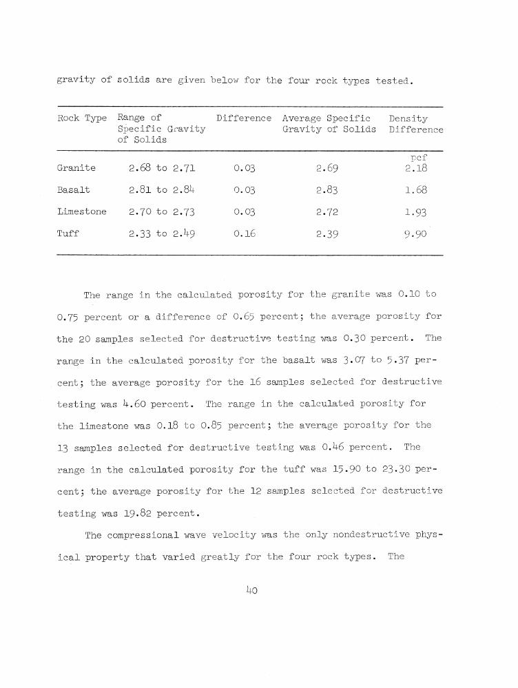
gravity of solids are given below for the four rock types tested.
Rock Type Range ofSpecific Gravity of Solids
Difference Average Specific Gravity of Solids
DensityDifference
Granite 2.68 to 2 .71 0.03 2.69pcf
2.18
Basalt 2.81 to 2.81+ 0.03 2.83 1.68
Limestone 2.70 to 2.73 0.03 2.72 1-93
Tuff 2.33 to 2.1+9 0.16 2-39
Oo^03
The range in the calculated porosity for the granite was 0.10 to
0.75 percent or a difference of O .65 percent; the average porosity for
the 20 samples selected for destructive testing was 0.30 percent. The
range in the calculated porosity for the basalt was 3*07 to 5*37 per
cent; the average porosity for the 16 samples selected for destructive
testing was 1+.60 percent. The range in the calculated porosity for
the limestone was 0.18 to O .85 percent; the average porosity for the
13 samples selected for destructive testing was 0.1+6 percent. The
range in the calculated porosity for the tuff was 15-90 to 23-30 per
cent; the average porosity for the 12 samples selected for destructive
testing was 19-82 percent.
The compressional wave velocity was the only nondestructive phys
ical property that varied greatly for the four rock types. The
1+0

following tabulation gives the range in velocity, the difference, and
the average velocity for those rock samples that were destructively
tested.
Rock Type Range in Compressional Wave Velocity
Difference Average Compressional Wave Velocity
ft /sec ft/sec ft /sec
Granite 17,^00 to 19,¥+0 2 , 0U0 18,¿+50
Basalt 15,270 to 17,760 2,^90 16,6 30
Limestone 19,885 to 22,320 2,^35 2 0 ,710
Tuff 6,597 to 8,810 2,213 7,890
The reproducibility of the compressional wave velocity through
the aluminum transducer holders and of the electronic components used
in conjunction with the transducers was checked and found to be very
good. The difference in the velocity, later referred to as the delay
velocity, of the aluminum holders for a series of nine readings was
less than one percent.
Prior to testing the cores for compressional wave velocities, a
granite and a basalt sample were tested for reproducibility of wave
velocities, A series of six velocities was recorded for each sample;
this was accomplished by placing the core between the transducers, re
cording the velocity, and then removing the core. The difference in
the velocities for the granite was 2.6 percent and for the basalt was
3.0 percent. This difference is attributed to the fact that the first
signal arrival is not sharply defined on the oscilloscope trace. In
most cases? however, the signal was fairly sharp; Figures 3-1 and 3-2
are typical photographs of the wave velocity trace recorded for the
four rock types used in this work. The signal arrival for the tuff
samples was less distinct than that for the other three rock types.
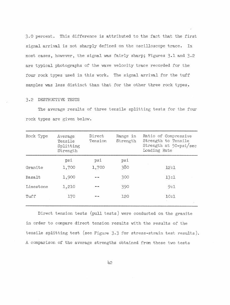
3.2 DESTRUCTIVE TESTS
The average results of three tensile splitting tests for the four
rock types are given below.
Rock Type AverageTensileSplittingStrength
DirectTension
Range in Strength
Ratio of Compressive Strength to Tensile Strength at 50-psi/sec Loading Rate
psi psi psiGranite 1,700 1,700 380 12:1
Basalt 1,900 -- 300 13:1
Limestone 1,210 -- 390 9:1
Tuff 170 -- 120 10:1
Direct tension tests (pull tests) were conducted on the granite
in order to compare direct tension results with the results of the
tensile splitting test (see Figure 3-3 for stress-strain test results).
A comparison of the average strengths obtained from these two tests
shows that the average strengths are identical; however, the range of
individual data is greater for the tensile splitting test than for the
direct tension test. There is very little data from which to conclude
any distinct advantage of one method of tensile testing over the other
however? the test results indicate that the direct pull method is more
consistent. Logically, the direct method should give a truer tensile
strength because when the sample is pulled, it will fail along its
weakest plane, wherever that plane may be. In the tensile splitting
test, the plane selected for testing need not necessarily be the
weakest. The modulus of elasticity in tension is quite close to the
modulus calculated for specimens tested in unconfined compression.
There were three static unconfined compressive strength tests
conducted for each of the four rock types at a loading rate of
50 psi/sec. The basalt was then tested at 1, 500, 2.00 X 10^,
3.13 X id, 1.29 X 10⁷, 1 .3^ x 107, and 1.60 X 10⁷ psi/sec. A modulus
of elasticity E ’and a Poisson1 s ratio q were calculated for each
unconfined compression specimen tested. The modulus of elasticity is
A cta value calculated at one-half the ultimate strength, i.e., E = ,a,
where Act is the change in a,xial stress, and Ae is the change ^a,
axial strain. Poisson1 s ratio is also calculated at one-half the ulti
edmate strength, i.e., a = — , where e is the axial strain and en
r e a dais the diametral strain. The modulus of elasticity and PoissonTs

ratio calculated for the twelve unconfined compression tests are given in Tables 3«1 through 3«*+«
The modulus of elasticity values calculated for the static unconfined compression tests run on the granite rock compare quite closely with the in situ values reported in Reference 35. The work in Refer
ence 35 was conducted on rock similar to that tested in this investigation. The average modulus values for Sites 1 and 2 of Reference 35
6 6were 8.91 X 10 and 9-73 X 10 psi, respectively. The average modulus for the granite cores tested during this project was 10.70 x 10^ psi.
The unit volumetric strain was also calculated for the unconfined compression and the triaxial compression tests reported herein. This value was plotted with the stress versus axial and diametral strain
curves to determine at what stress level the instantaneous rate of change of volumetric change is zero; the volumetric change is zero when the slope of the volumetric strain curve changes sign. Unit volumetric strain was also plotted to determine if it could be correlated with a significant change in compressional wave velocity on the deviator stress versus compressional wave velocity curve. It was felt that when the volumetric strain was constant, possibly indicating that internal microcracks were closed, the compressional wave velocity might
be at its highest level. The results of this comparison will be given with the discussion of triaxial testing. According to the theory of elasticity, the unit volumetric change is given by:
44

(3.1), = 1 V E (<Ti + + a3)
where |i is the PoissonTs ratio and E is the modulus of elasticity-
taken at one-half the ultimate compressive strength.
The tuff samples tested in unconfined compression at natural
water content had compressional wave velocities V recorded parallel
to the applied stress at various increments of applied stress. These
tests were conducted in order to compare the change in velocity in the
unconfined state with the change in velocity in the confined state,
i.e., in the triaxial compression test. Figure 3* - shows the change
in compressional wave velocity with a change in the axial stress for
the tuff samples, and Figure 3*5 shows the 'V data obtained from
triaxial testing. A comparison of Figures 3*^ and 3*5 shows that the
compressional wave velocity of tuff is affected more by combined
stresses and than by axial stress alone. The average initial
velocity for samples tested in unconfined compression (Figure 3*^) was
6 ,9 8 0 ft/sec, while the average velocity for these samples at failure
was 8,300 ft/sec. This was an increase due to axial loading of
1,320 ft/sec. The average initial velocity for samples tested under
combined stresses was 7>3^-0 ft/sec, while the average velocity at fail
ure up to 1,500 psi, cj 5 was 9 A30 ft/sec. This was a 1,790-ft/sec
increase. The compressional wave velocity increased faster under com
bined stresses than under axial stress only. This was due to the fact
^5

that a confining pressure tends to consolidate the specimen uniformly,
thereby closing internal cracks and causing V to increase morePsharply.
Generally the granite specimens tested in unconfined compression
at both slow and rapid rates of loading failed in shear; however, a
few failed by vertical splitting. Two basalt specimens tested at a
loading rate of 50 psi/sec failed on high-angle planes of approxir
mately 70 degrees, and one failed by vertical splitting.
The three limestone specimens failed by vertical splitting, while
the tuff specimens failed on planes approximately 65 degrees from the
horizontal. The high shear angle, approximately 65 degrees for the
granite and the basalt, was probably caused by localized stress con
centrations within the constrained regions of the specimens. If the
specimen length-to-diameter ratio were increased from 2 to about 2.5,
then possibly the failure angle would develop in the specimen midsec
tion outside the constrained regions. Typical basalt shear breaks are
shown in Figure 3-6.
Most of the available rock mechanics literature that was received
showed that brittle rock, such as granite and basalt, fails by verti
cal splitting when tested in unconfined compression. This has been
the case at the WES laboratory in the past. However, it was found
that when the specimen ends of brittle rocks were surface ground, hand
lapped, and tested without a capping material, higher unconfined
k6

compressive strengths and pronounced shear failures were obtained.This was found to be true at various rates of loading when the samples were held within close tolerances; the ends were ground plane to 0.001 inch5 were perpendicular to the side of the specimen within
0.5 degrees? and were parallel to within 0.006 inch.
Figures 3*7 through 3*31 show the relation of stress to axial, diametral, and volumetric strains of rock specimens tested in unconfined compression. The slow stress-strain curves for the granite,
basalt, and limestone rocks behave elastically to failure, and the mode of failure is brittle. The rapid stress-strain curve for the
granite behaves elastically to about $ 0 percent of ultimate strength. The rapid stress-strain curves for the basalt behave elastically to about k-5 percent of ultimate strength, then behave plastically to failure. The rock is characterized by a slight ductile failure.The dynamic stress-strain curves for the limestone are highly irregular; however, there is no clear explanation for this. Both the slow and rapid stress-strain curves for the tuff rock behave plastically, then elastically, and then plastically again towards failure; the mode of failure is ductile.
Results of the slow and the rapid unconfined compression tests show a significant difference in ultimate strength and total axial strain with the exception of the granite. The granite (Operation
Flint Lock, Shot Pile Driver, NTS) used for the unconfined compressive

strength tests was weaker than the same granite tested in the past at
the Concrete Division, WES, and at the Missouri River Division Labora
tory, Omaha, Nebraska. Previous tests have shown that the slow compressive strength of the Pile Driver granite ranges from about 19,000 to about 31,000 psi, with an average of 25,000 psi (Reference 36). Evidently, the granite cores used for testing in this program were at the lower end of the strength range. The dynamic compressive strength factor f^ for granite was less than one.
Both strength and total axial strain at failure for the limestone and the tuff increased under rapid loading. The f ^ for the limestone was 1 .52, and the axial strain at failure under rapid loading was approximately 2.6 times greater than the strain under slow loading. The f^ for the tuff was I.7U, and the increase in axial strain at failure was about 2,267 M*in, or about 1.6 times greater under rapid loading. The tuff f^ appears to be quite high
compared with that of the other two rock types; however, additional rapid testing would have to be done to determine the validity of this factor.
As stated earlier, the basalt rock was selected for further con
fined and unconfined compressive testing. Additional triaxial tests were run at loading rates of 1, 500, and 2,250 psi/sec, and additional unconfined tests were run at loading rates of 1, 500, and 2.06 X lCr psi/sec. In summary, the loading rates for the basalt

rock ranged from 1 to 1.60 x 10 psi/sec. The average slow compres
sive strength of the basalt was 21,460 psi, and the rapid compressive strength was 29,020 psi. This is an increase of 7*560 psi for a compressive strength factor f^ of 1.35* The difference between
the average rapid and the average slow axial strain at failure was
2?9 -0 |j,in/in, with the rapid strain being greater. Slow diametral strain at failure was slightly greater than the rapid strain at
failure, i.e., l40 (jin/in greater. Figures 3*32 and 3«33 show the effects of increased rates of load on the unconfined compressive strength and total axial strain at failure of the basalt specimens.It can be seen from these graphs that loading rates up to 500 psi/sec do not have a pronounced effect on total axial strain and only a slight effect on the compressive strength. However, at higher rates of loading both strength and axial strain increase considerably. Figure 3*32 is a plot of the relation between loading rates and ultimate compressive strength. This plot definitely shows a considerable increase in strength with an increase in rate of loading. The curve of best fit for the data is very good for both ends of the curve;
however, the center portion of the curve could be improved consider-3 6ably if additional data were obtained between decades lCr and 10 .
The data were fitted with a least-squares polynomial curve fit program taken to the third order, GE program No. CD 225H6.004, with the
2 3form y .= a + bx + cx + dx .
7
Intuitively one might expect that total axial strain at failure
would decrease with an increase in rate of loading. This is graphi
cally shown in Figure 1.1 for relatively low rates of loading. How
ever 5 the test data presented herein show this not to be true at
faster loading rates. Reference 37 reports that similar results were
observed during testing of concrete cylinders utilizing stressing
rates ranging from 7*1 to 1.7 X 10^ psi/sec. Results of tests re
ported in Reference 38 also indicated an increase in axial strain at
failure with an increase in stressing rates.
One explanation for the increase in rapid axial strain at failure
over slow axial strain at failure may be the fact that as the rock
begins to fail under dynamic loading, the rock midsection on which
the strain gages are bonded breaks away intact and continues to
strain. High-speed movies taken at WES of rock cores failing under
rapid loads show that the core fails in a cone break. This type
of break normally leaves the midsection intact after failure.
A curve of best fit for the strength-strain data shown in Fig
ure 3-33 was judged to be in the form of a curvilinear equation of
form y = ax^ . The solution for the equation coefficients, a and b ,
and other pertinent statistical parameters was handled by a computer
program, OCE No. 0U-G1-Z5-002 (Reference 39)• This program uses the
method of least squares for a curvilinear regression to determine the
50

eq u ation c o e f f i c ie n t s o f th e l in e o f b e s t f i t fo r th e input d a ta .
F igu re 3.3k shows the r e la t io n o f lo ad in g r a te and t o t a l a x i a l
s t r a in a t f a i lu r e fo r b a s a l t . F igu re 3 .35 shows th a t with an in c re a se
in lo ad in g r a t e , the t o t a l d iam e tra l s t r a in a t f a i lu r e d e c re a se s
s l i g h t l y . F igu re 3*36 shows the r e la t io n o f lo ad in g r a te and modulus
o f e l a s t i c i t y taken a t o n e -h a lf the u ltim a te com pressive s tre n g th .
The v a r ia t io n in modulus a t a g iven lo ad in g r a t e i s q u ite w ide, and
a d d it io n a l d a ta should be developed to v e r i f y the in c re a se in modu
lu s with in c re a se d r a t e s o f lo a d in g . Curves o f b e s t f i t were ob tain ed
by u sin g the p re v io u s ly mentioned OCE computer program . ^
F ig u re s 3 .37 through 3-58 show th e r e la t io n o f d e v ia to r s t r e s s
(o^ - cr^) to a x i a l , d ia m e tra l, and v o lu m etric s t r a i n s . F ig u re s 3 .5 9
through 3 .6 l and F igu re 3-5 g iv e r e s u l t s o f th e com pression al wave
v e lo c i t y t e s t s and show th e r e la t io n between wave v e lo c i t y and d e v i
a to r s t r e s s . F ig u re s 3 .62 through 3 .68 are p lo t s o f Mohr c i r c l e s th a t
show the r e la t io n o f normal s t r e s s to sh e arin g s t r e s s ; th e an gle o f
in te r n a l f r i c t i o n and th e sh e arin g s t r e s s c are g iven fo r each
rock ty p e . These f ig u r e s a l s o show th e observed f a i lu r e p lan e in the
c o re . D ata from b a s a l t rock t e s t e d in t r i a x i a l com pression a t lo a d
in g r a t e s o f 1 , 50 , 500, and 2,250 p s i / s e c are in te r e s t in g in re g a rd
to th e lo a d in g r a t e s a t a s p e c i f i c co n fin in g p re ssu re o^ . F igu re
3.52 shows th a t a t o ^ 's o f 250 and 1 ,000 p s i th e maximum d e v ia to r
s t r e s s ct in c re a se d with in c re a se d lo ad in g r a t e except fo r the
51

specimens loaded at 50 psi/sec. At a of 5,000 psi, a in
creased throughout the full range of loading rates used. Total axial
strain increased in all cases with an increase in loading rate at
each of the used except at a a 250 psi and a loading
rate of 50 psi/sec.
From the data presented for the unconfined compression tests
(Figure 3.69) and the above-described triaxial compression tests, it
is evident that at least the basalt rock behaves consistently under
various rates of loading, i.e., both strength and axial strain
increase.
The tuff rock was the only one tested that showed a decrease in
deviator stress with increased confining pressures. The rock was
tested at a natural moisture content of approximately 21 percent and
in the undrained state. The pore pressure buildup due to confining
pressure and axial loading probably caused the pore pressure to break
down some of the rock structure, thereby causing lower strengths at
increased confining pressure. This fact is cited a. number of times
in the literature that was reviewed. Should additional triaxial
testing be done, the effect of pore pressure should definitely be
accounted for in terms of effective stresses . a' = a - u , where ar=
effective stresses, a = applied axial stress, and u = pore pressure .
The results of the compressional wave velocity tests, which were
conducted along with the triaxial compression tests, agree quite well
52

w ith th e t e s t r e s u l t s found in th e l i t e r a t u r e s e a r c h . T here were
tw e lv e t e s t s ru n , and in a l l c a se s e x c e p t one th e co m p re ss io n a l wave
v e l o c i t y in c r e a s e d s h a r p ly when th e a x i a l s t r e s s was in c r e a s e d t o
about o n e - h a lf o f th e u lt im a te s t r e s s . The v e l o c i t i e s th en le v e le d
o f f u n t i l j u s t b e fo r e f a i l u r e ; a t f a i l u r e , th e y e i t h e r rem ained con
s t a n t o r d e c re a s e d s l i g h t l y . V e l o c i t i e s a ls o in c r e a s e d w ith in
c r e a s e d c o n f in in g p r e s s u r e . The in c r e a s e s in v e l o c i t y from ze r o t o
maximum d e v ia t o r s t r e s s f o r th e ro c k s t e s t e d a r e g iv e n b e lo w :
Rock F a c to r by Which V e l o c i t i e s In c re a s e d a t C o n fin in g P r e s s u r e s
I n d ic a te d
250 500 1,000 1,500 ¿*,000 5,000
p s i p s i p s i p s i p s i p s i
G r a n ite 1.0 9 — 1 .1 0 — 1.0k —
B a s a lt 1 .0 3 — 1.0 6 — — 1.12
L im eston e 1.10 — 1.0U — — 1.10
T u f f — 1 .2 3 1.21 1 .2 7 — —
No d i s t i n c t c o r r e l a t i o n c o u ld be made betw een th e co m p re ss io n a l
wave v e l o c i t y v e r s u s d e v ia t o r s t r e s s and th e v o lu m e tr ic s t r a i n v e r s u s
d e v ia t o r s t r e s s c u r v e s . G e n e r a lly th o u g h , th e co m p re ss io n a l wave
v e l o c i t y cu rv e was a t a c o n s ta n t l e v e l , o r a t i t s h ig h e s t v a lu e when
th e v o lu m e tr ic cu rv e was e x p a n d in g , i . e . , j u s t a f t e r th e v o lu m e tr ic
change was c o n s t a n t .
53

For all practical purposes, the straight-line relation described
by Mohr’s criterion T = c + a tan ft where T is the shearing
stress, c is referred to as cohesion, o is normal stress on the
failure plane, and ft is the angle of internal friction, fits most
of the stress circles presented for the granite and basalt. A curvi
linear analysis would best fit the stress circles presented for the
limestone rock. No envelope was drawn for the results of the tuff
rock due to the decrease in deviator stress with increased .
Nearly all the observed shear failure planes did approach those pre
dicted from MohrTs criterion (ft = $0 - 2 a ). This can be seen in the
following tabulation.
Rock LoadingRate °3 Observed
FailureAngle
Predicted Failure Angle ft = 90 - 2a
Envelope
psi/sec psi degrees degrees degrees
Granite 50 250 52 72 5b
Granite 50 U ,000 50 72 5b
Basalt 1 1,000 6l 77 —
Basalt 1 5,000 — — —
Basalt 50 250 60 72 5^
Basalt 50 1,000 63 72 5b
Basalt 50 5,000 63 72 5b
Basalt 500 25O 71 70 50(Continued)

Rock Loading ff3 Observed Predicted EnvelopeRate Failure Failure Angle
Angle f = 90 - 2-Oi
psi/sec psi degrees degrees degrees
Basalt 500 1,000 75 70 50
Basalt 500 5,000 70 70 50
Basalt 2,250 1,000 lh 73 55
Basalt 2,250 5,000 72 73 55
Figure 3.70 shows Mohr (snvelopes for the basalt rock at loading
rates of 1, 50? 500? and 2,250 psi/sec. 1There is very little dif-
ference in / at the lower T s and at the higher T s with the
exception of the envelope developed from specimens loaded at a rate
of 50 psi/sec. The / T s of envelopes at the tangent point of the
1,000- and the 5?000-psi cr stress circles are presented below.
1,000-psi Circle 5,000-psi o’2 Circle
Loading Rate ? Loading Rate 0psi/sec degrees psi/sec degrees
1 -- 1 --
50 5^ 50 16
500 50 500 ^ 7
2,250 55 2,250 k6
55

The data on the previous page indicate that basalt under triaxial
stresses is not greatly affected by loading rates ranging from 1 to
2?250 psi/sec with regard to 0 , and that MohrTs criterion of
failure fits the basalt rock quite well. Generally, the observed
angles of failure do increase with increased rates of load at a given
confining pressure; however, the method of measuring these angles is
rather crude and not taken as very accurate. The cohesion values for
the loading rates used are presented below:
Loading Rate Cohesion (c)
psi/sec psi
1 —
50 3,800
500 3,900
2,250 3,700
Here again there is no clear indication that loading rates signifi
cantly affect cohesion of basalt at rates up to 2,250 psi/sec.
Figures 3*71 through 3«73 are charts showing the engineering
classification for the intact rock specimens tested during the proj
ect. This classification system is the one referred to earlier in
Reference 32. Generally, the data reported herein fell very close
to similar rock data plotted in Reference 32.
Figures 3*7- and 3*75 show the relation of axial stress to
56

lateral stress at failure in triaxial compression at various loading
rates for the rock tested during this program. The data shown in
Figure 3*3^ are consistent with data found in the literature search.
However5 there were no data found during the literature search on any
one rock that had been subjected to triaxial loading at different
loading rates. The results of this investigation show that as the
rate of loading is increased, for a set of confining pressures, a
straight-line equation exists; the samples tested at a loading rate
of 50 psi/sec are an exception to this statement.
57-58


TABLE 3 .1 TEST RESULTS FOR GRANITE
SpecimenNo.
Hole No. Depth SpecificGravityBulk Solids Dry
Porosity
Compres-sionalWaveVelocity
DirectTension
TensileSplittingStrength
Slow Compression Rapid CompressionUnconfined Compressive Strength Test
Triaxial Compressive Strength with Compressional Wave Velocity (V )
Unconfined Compressive Strength Test
LoadingRate
Strength Y o u n g * s Modulus
Poisson* s Ratio
Strength at Confining Pressures of 25 0, 1,000, and t,000 psi250 1,000 it,000
Young’sModulus
Poisson * s Ratio
InitialVP
HighV
P
Loading Strength Rate
Young * s Modulus
feet pet ft/sec psi psi psi/sec psi_ 106 psi psi psi psi 106 psi ft/sec ft/sec psi/sec psi 106 psiG-l U-1501-U2 11.1 to 11.7 2.69 2.70 0 .3 3 18,8I+0 — 1,5 0 — — — — — — — — — — — --G-2 U-1501-U2 73.2 to 2.69 2.70 0 .3 3 18,590 — — 50 19,790 10.20 0.22 — — — — -- — — —G -h U-I5-I7 52.6 2 .7 1 2.71 0.10 18,820 — — -- — — — — 52,5^0 10.00 O.29 20,660 21,8t0 — —G-5 U-I5OI-UI 728.0 to 730.2 2.68 2.70 0.63 18,270 — 1,630 — — — — — — — — — -- — —g - 6 U-I5-27 121.0 2.69 2.70 O.29 18,550 1 ,770 — — — — — — — — — . -- — — —G-7 U-15E-01 9 9 . b 2.68 2.70 0 .6 3 18,000 — — — — — — — 29,320 11.30 0.22 18,000 19,9^0 —G-8 U-I5OI-UI 728.0 to 730.2 2.68 2.69 0 .3 3 17,500 1 ,770 — — — — — — — — — -- — — —G-IO U-I5OI-UI 728.0 to 730.2 2.68 2.69 0.29 19,230 — ~ 50 2 0,ltO II.60 0.22 — — — — — — — —G-ll U-I5OI-UI I7O9.O to I7IO.7 2.70 2.70 0.11 19,220 — — — — — — — — — — — — 66.03 x 10 18,070 IO.5IG-13 U-I5OI-UI 1709;o to 1710.7 2.66 2.68 0 .75 17,1+00 — — — -- — — — — — — — — 6.95 x 10⁶ 20,960 10 .03
G-15 U-I5OI-UI 1759.9 to 1760.9 2.70 2.71 0.11 19,M+o ~ — 50 22,290 IO.3O 0.22 — — — — — -- — --G-16 U-I5-27 178.0 2.68 2.69 0 .3 7 18,720 — 1,920 — — -- — — — — — — -- -- --G-17 U-15E-01 106.5 2.70 2.70 0.11 17,860 — — — — — — — — — — — -- — --G-18 U-I5OI-UI 1759.9 to 1760.9 2.70 2.71 0.11 18,380 — — — — — — — — — — -- — -- --G-19 U-1501-U1 — 2.69 2.69 0.22 18,660 — — — — — — -- — — — -- — -- --
G-20 U-I5OI-UI — 2.68 2.69 0 .7 7 18,250 — — — — — — 2t,120 — 10.70 O.25 18,250 20,050 — —
G-21 U-1501-U1 — 2.70 2.70 0 .0 3 18,270 — — — — — — — — — — -- — — --
G-22 U-I5-27 121.0 2.69 2.70 O.29 18,500 — — — — — — — __ -- — -- -- -- --
G-23 U-I5OI-UI — 2.68 2.69 o . t 6 18,260 — — — — — — — — — -- — -- -- --
G-2t U-1501-U1 — 2.68 2.69 0.37 18, 70 — — — — — — — — — — — — — —
Average 2.69 2.69 0.30 18, it 50 1 ,770 1,770 20,7t0 IO.7O 0.22 19,510 1 0 .27
59-60


TABLE 3.2 TEST RESULTS FOR BASALT
S p e c -menNo.
H oleN o.
D epth S p e c i f i cG r a v i t y
P o r o s i t y
C om pres-s i o n a lWaveV e l o c i t y
T e n s i leS p l i t t i n gS t r e n g t h
S lo w C o m p re ssio n R a p id C o m p re ssio n Mode o f :F a i lu r e
Unc o n f in e d C o m p re ss iv e S t r e n g t h T e s t
T r i a x i a l C o m p re ss iv e S t r e n g t h w it h C o m p re ss io n a l Wave V e l o c i t y (V p )
U n c o n fin e d C o m p re ssiv e S t r e n g t h T e s tB u lk
D ryS o l i d s
L o a d in gR a te
S t r e n g t h Y o u n g ' s M odulus
P o i s s o n 'sR a t io
L o a d in gR a te
S t r e n g t h a t C o n f in in g P r e s s u r e s o f 250, 1 ,0 0 0 , and 5 ,0 0 0 p s i
250 1 ,0 0 0 5 ,0 0 0
Y o u n g ' s M odulus
P o i s s o n 'sR a t io
I n i t i a lV
P
H ig h e s tV
P
L o a d in gR a te
S t r e n g t h Y ou ng' s M odulus
P o is son ' s R a t io
f e e t p e t f t / s e c p s i p s i / s e c p s i 10^ p s i p s i / s e c p s i p s i p s i 10^ p s i f t / s e c f t / s e c p s i / s e c p s i 10^ p s i
B - l DA-1 75.3 t o 76.5 2 .7O 2.83 15,61+0 - 1 21,370 1+ .66 0 .2 6 - - - - - - - - - - - - - - -
B-2 NCG-38 - 2 .6 8 2.83 5 .2 6 15,650 1 ,8 2 0 - - - - - - - - - - - - - - - - - - -
B-3 DA-1 1 3 8 .2 t o 1^ 0 .0 2.67 2 .8 2 5.35 16,350 - 500 2 1 ,8 1 0 1+.80 0 .2 9 - - - - - - - - - - - - S h e a r a t 60 d e g r e e s fro m h o r i z o n t a l
B-U DA-1 1 3 8 .2 t o 1U 0 .0 2.67 2 .8 2 5.35 16,370 - - - - - 50 30,000 - - b . 6 o 0 .2 2 16 ,0 6 0 1 6 ,5 1 0 - - - - - S h e a r a t 63 d e g r e e s fro m h o r i z o n t a l
B-5 NCG-^+2A 68.5 2 .6 6 2 .8 2 5.37 1 6 ,0 9 0 - - - - - 50 - 3 6 ,9 8 0 - 1+.90 0.17 16 ,0 2 0 17,130 - - - - - -
b -6 NCG- +5 73.9 2.73 2 . 81+ 3.^7 1 5 ,2 7 0 - 5OO 21,1+10 5-37 0 .3 2 - - - - - - - - - - - - -
B-7 C a le x - 2 .6 9 - - 16 , 1+30 - 5OO 2 2 ,3 1 0 1+.00 0 .2 5 - - - - - - - - - - - - - - -
B -8 C a le x - 2 .7 1 - 1 6 ,8 9 0 - - - - - - - - - - - - - - 2 .0 6 x 1 0 5 2l+,970 3.61 0.27 -
B-9 - 1 5 6 .8 2.73 2 . 81+ 3.59 1 5 ,6 7 0 - 50 2 2 , 7l+0 1+.17 0 .2 9 - - - - - - - - - - - - - -
B-10 - I 5 7 . I 2.73 2 . 81+ 3.59 16,1+90 - - - - - - - - - - - - - 3 .1 3 X i o 6 2 8 ,1 7 0 5.OO O.U5 -
B - l l C a le x 2 .7 0 - - 16,730 - - - - - - - - - - - - - 2 .0 6 x 10 5 2 7 ,5 2 0 3-^2 O .39 -
B-12 NOG-23 I+9.O 2 .7 ^ 2 .8 3 3.07 1 7 ,7 0 0 1,790 - - - - - - - - - - - - - - - - - - -
B-13 DA- 2 95.0 t o 9 6 .5 2 . 7 k 2.83 3.11 1 7 ,7 6 0 - - - - - 5OO 2 5 ,6 2 0 - - - 1+.1+6 0.37 - - - - - - - - S h e a r a t 71 d e g r e e s fro m h o r i z o n t a l
B - l k I 3 . 2 2 .6 8 2 .8 3 5 .2 6 17,650 - - - - - 1 21,21+0 - - - 5 .1 8 0.1+1 - - - - - - - - V e r t i c a l s p l i t t i n g
B-15 NCG-^+O 61.3 2 .6 8 2 .8 3 5 .2 6 1 5 ,U 6 o - - - - - - - - - - - - - - 2 .0 6 X 10 5 23,360 2 .7 1 O.35 -
B - l6 NCG-i+O 6 1 .3 2 .6 8 2 .8 3 5 .2 6 15,910 - - - - - - - - - - - - - 1 .6 0 x i o 7 3 2 ,1 2 0 ^.73 O .23 -
B-17 NCG-38 6 k . k 2 .6 9 2 .8 2 1+.61 17,550 - - - - - - - - - - - - - 1 .2 9 x i o 7 32,390 1+.68 0.. 20 -
B-18 NCG-38 6 k . h 2 .6 9 2 .8 2 1+.61 1 7 ,6 5 0 - - - - - - - - - - - - - 1.31+ x 10 7 3!+,580 6 .6 6 O.25 -
B-19 DA-2 6 7 .8 2 .6 8 2 .8 2 5 .2 0 1 7 ,3 6 0 - - - - - • 50 - - 1+6,280 6 .0 8 0 . l 6 1 6 ,6 7 0 18,750 - - - - - - S h e a r a t 63 d e g r e e s fro m h o r i z o n t a l
B-20 DA- 2 6 7 .8 2 .6 8 2 .8 2 5 . 21+ 17 ,200 - 50 20,730 1+.25 - - - - - - - - - - - - - - - -
B-21 C a le x - 2 .7 0 - - 16 ,8 0 0 - 1 2 2 ,5 8 0 1+.71 O.UU - - - - - - - - - - - - - - -
B-22 C a le x - 2 .7 0 - - - 1 6 ,8 5 0 - 1 1 8 ,9 2 0 3.^8 0 . 1+7 - - - - - - - - - - - - - - -
B-23 C a le x - 2 .7 0 - 1 6 ,5 0 0 - - - - - 1 - 2 7 ,8 8 0 - 4 .1 9 0 . k 3 - - - - - - - - S h e a r a t 6 l d e g r e e s fro m h o r i z o n t a l
B - 2U C a le x - 2 .6 9 - ~ 1 6 ,1 0 0 - - - - - 1 - - 3 3 ,^ 3 0 1| .6-; 0 .2 2 - - - - - - - V e r t i c a l s p l i t t i n g
B-25 C a le x - 2 .6 8 - - 1 6 ,2 5 0 2 ,0 9 0 - - - - - - - - - - - - - - - - - -
B-26 C a le x - 2 .6 9 — 16,950 - - - - - 5OO - 31,290 - 3 -9 . 0.27 - - - - - - S h e a r a t 75 d e g r e e s fro m h o r i z o n t a l
B-27 C a le x - 2 .7 1 - - 1 7 ,1 0 0 — - - - - - 5OO - - 1+9 ,13 0 k . k 2 0.31 - - - - - - - S h e a r a t 70 d e g r e e s fro m h o r i z o n t a l
B-28 C a le x - 2 .7 0 - - 16 ,2 ^ 0 - - - - - - . 2, 7l+0 2 5 ,7 0 0 - - 1+.00' 0 .2 5 - - - - - - - V e r t i c a l s p l i t t i n g
B-29 C a le x - - 2 .6 9 - 15,990 - 50 2 1 ,2 5 0 5 .0 0 0 .2 6 - - - - - - - - - - - - —
B-30 C a le x - 2 .7 2 - - 1 6 ,9 8 0 - - - - - 2 ,2 5 0 - - 3 5 ,0 1 0 - 1+.71 0 .2 5 . - - - - - - - S h e a r a t 7 + d e g r e e s fro m h o r i z o n t a l
B-31 C a le x - 2 .7 0 - - - 1 6 ,8 9 0 - - - - 2 ,2 5 0 - - 5l+,000 5.O 3 0.15 - - - - - - S h e a r a t 72 d e g r e e s fro m h o r i z o n t a l
A v e ra g e 2 .6 9 2 .8 3 1+.60 1 7 ,l l+ 0 1 ,9 0 0 21,1+60 0 .3 2 2 9 ,0 1 0 4.^0 O .3 I
L \ . i iQ
61-62


TABLE 3.3 TEST RESULTS FOR LIMESTONE
SpecimenNo.
HoleNo.
Depth SpecificGravity
Porosity
Compressi onal WaveVelocity
TensileSplittingStrength
Slow Compression Rapid Compression
Unconfined Compressive Strength Test
Triaxial Compressive Strength with Compressional Wave Velocity Up)
Unconfined Compressive Strength TestBulk
DrySolids
LoadingRate
Strength Young's Modulus
Poisson Ts Ratio
Strength at Confining Pressures of 2 5 0 , 1,000, and U,000 psi250 1,000 U,000
Young'sModulus
Poisson^Ratio
InitialVP
HighestVP
LoadingRate
Strength YoungT s Modulus
Poisson'sRatio
feet pet ft/sec psi psi/sec psi 10^ psi psi psi psi 106 psi ft/sec ft/sec psi/sec psi i rß10 psi
L- 2 FT-1 . 3 5.5 to 6.5 2.68 2.70 0.81 19,890 -- 5 0 9,500 10. k2 0.19 -- -- -- -- -- -- -- -- -- --
L-k FT-1 . 1 12.1 to 12.8 2 . 7 1 2 . 7 3 O.69 20,580 -- -- -- -- -- 1 5 ,1 ^ 0 10.80 0 . 3 5 20,220 22,250 -- -- -- --
l-6 FT- 1 68.0 2.72 2 - 7 3 0I3 20,990 -- -- -- -- -- — -- -- — -- -- -- -- --
L- 7 FT- 1 69.O 2.72 2 . 7 3 o lo 20,690 -- 5 0 1 2 , 7 5 0 12.00 0.29 -- 25,200 11.80 0.32 21,060 21,960 — -- -- --
l-8 FT- 1 82.0 2.70 2 . 7 1 0.22 20,760 -- 5 0 11,300 11.28 0.30 -- -- -- -- -- -- -- -- -- --
L- 1 0 — — 2.70 2 . 7 1 0 . 3 3 21,580 -- -- — -- -- -- -- -- -- -- -- — -- -- --
L- 1 2 FT-1 . 0 8 1 to 9.1 2 . 7 1 2 . 7 3 0 . 5 5 20,250 -- -- -- — -- -- 31,630 9.82 0 . 3 2 19,880 2 1 , 9 3 0 — -- -- --
L- 1 3 FT-1 . 0 13.6 to 1.8 2.68 2.70 O.85 1 9 , 7 0 0 l,k 6o -- -- -- -- -- -- -- -- -- — -- -- --
L-lU FT-1 . 1 8.0 to 8.8 2 . 7 1 2 . 7 3 0 -5-5 20,^90 1,100 -- -- -- -- -- — -- -- -- -- -- -- -- --
L- 1 5 FT-1 . 3 5-5 to 6.5 2.70 2 . 7 1 0.29 19,890 1,070 -- -- -- -- -- -- -- -- — -- -- -- -- --
L- 1 7 FT- 1 18.6 2.70 2 . 7 1 OlO 22,320 -- -- -- -- -- -- -- -- -- — -- 1.87 x 10⁷ 3 7 , 2 9 0 1 2 . 0 3 o.ko
L-l8 FT- 1 62.8 2 . 7 1 2.72 0.29 20,930 -- -- -- — -- -- — — -- -- 5.80 X 10⁶ 29,000 II.76 0.35L- 2 0 FT- 1 27.8 2 . 7 1 2.72 0.18 2 1 , 1 5 0 -- -- — -- -- -- -- — — --
£1I9 x 10 1 ^ , 9 3 0 7.61 0.U6
Average 2.70 2.72 0 1 6 20,710 1,210 11,180 11.23 0.26 27,070 1 0 1 6 olo
63-6b


TABLE 3.li- TEST RESULTS FOR TUFF
SpecimenNo.
Hole No. Depth SpecificGravity
Porosity
Natural Water Content
Compres-sionalWaveVelocity
TensileSplittingStrength
Slow Compression Rapid Compression
Unconfined Compressive Strength Test
Triaxial Compressive Strength with Compressional Wave Velocity (7p)
Unconfined Compressive Strength TestBulk
DrySolids Before
TestAfterTest
LoadingRate
Strength YoungT s Modulus
Poisson^Patio
Strength at Confining Pressures of 250, 1,000, and 1,500 psi
250 1,000 1,500
YoungT s Modulus
Poisson'sRatio
In itia l
VP
HighestV
P
Loading Strength Rate
Young' s Modulus
Poisson Ts Patio
feet pet ft/sec psi psi/sec psi 10 psi psi psi psi 1 rß10 psi ft/sec ft/sec psi/sec psi 106 psi
T-7 U12 GO 6ul+ 1 0 .0 to 1 2 .0 1-93 2-39 19.38 23.2 17-!+ 6,600 -- 50 1,560 0.k3 0.13 -- -- -- -- -- -- -- -- -- --
T -ll U12 GO 6ui+ 31.5 to 37.0 1.85 2.3!+ 21.77 22.1+ l 6 . 6 8,61+0 -- -- -- - - -- -- -- -- -- -- -- 8.1+6 x 10⁵ l+,230 0 .9 1 0.36
T-13 U12 GO 6ui+ 31.5 to 37.0 1.92 2.1+1+ 2 1 .1 0 2 1 .0 17.1 7,190 210 -- -- -- -- -- -- -- -- --
T-ll+ U12 GO 6\Jb 1+1. b to 1+2.9 I.9I+ 2.35 17.60 19.7 15.7 8,810 -- — -- -- -- -- - 3,560 0.878 0.19 7,5 7 5 9,61+1+ -- -- -- --
T-15 U12 GO 6ul+ 1+1.1+ to 1+2.9 I.9I+ 2 .1+3 20.30 19-7 15.6 7 , 1+70 130 -- -- -- -- -- -- -- -- -- -- -- -- --
T-20 U12 GO 6uk 67.7 to 72.0 1.92 2.35 18.39 20.1+ 17.1 7,610 -- -- -- -- -- -- 3,610 0.333 0 .1 7 6 , 9 ^ 8 M 3 -- -- -- --
T-21 U12 GO 6ui+ 67.7 to 72.0 1.92 2.1+0 20.29 17.1 ll+.l 7,670 — -- - - - - -- U,910 - - 0.91+7 0.25 7 ,5 3 2 9 ,8 59 - - -- -- - -
T-23 U12 GO 6vb 67.7 to 72.0 I.98 2.35 15.90 21+.7 20.6 8,060 250 - - - - - - -- -- -- -- -- -- -- - - -- - -
T-21+ U12 GO 6ul+ 67.7 to 72.0 1.89 2.33 18.95 23.5 17.6 8,190 -- -- -- -- -- -- -- - - -- -- - - 1 . 6 8 x io5 1,850 0 .33 0.^2
T-25 U12 GO 6ul+ 67.7 to 72.0 1.91 2.1+9 23.30 20 .2 16.3 8,190 - - 50 .1,670 0 .7 7 0.2k -- -- -- -- -- -- - - -- - - - -
T-26 U12 GO 6ul+ 67.7 to 72.0 1.91 2.1+1+ 21.80 20 .2 16.5 8,000 — 50 1,680 0.1+0 0.19 -- -- -- -- -- -- -- - -- --
T-27 U12 GO 6uk 67.7 to 72.0 1.91 2.36 19.06 21.9 19.1 8,280 -- -- - - - - - - - - -- -- -- -- -- 3.11 x 10⁵ 2,1+90 0.1+1 0.^9
Average 1.92 2.39 19.82 21.1 16.9 7,891 197 1 , 61+0 0.53 0.19 2,860 0.55 0.1+2
65-66

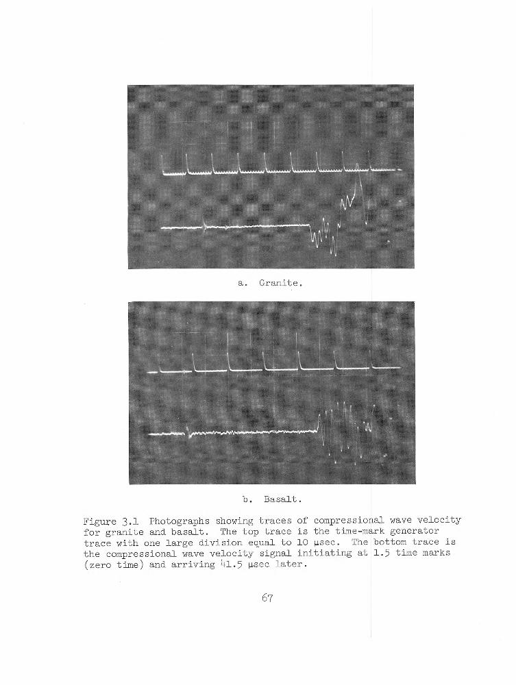
b. Basalt.
Figure 3.1 Photographs showing traces of compressional wave velocity for granite and basalt. The top trace is the time-mark generator trace with one large division equal to 10 |isec. The bottom trace is the compressional wave velocity signal initiating at 1.5 time marks (zero time) and arriving ^1.5 |isec later.
67

a. Limestone.
b. Tuff.Figure 3.2 Photographs showing traces of compressional wave velocity for limestone and tuff.
68

Tensll* 8trut| p*i
Strain, pin/in
Figure 3*3 Direct tensile stress versus axial strain, granite.

Compressional
Wave
Velocity, f
t/sec
Figure 3.h Compressional wave velocity versus axial stress, tuff in unconfined compression*

Comp
ress
iona
l Wa
ve V
eloc
ity,
ft/
sec
0 2 4 6Deviator Stress, 10 psi
Figure 3*5 Compressional wave velocity versus deviator stress, tuff.

Figure 3-6 Typical basalt shear breaks.
72

/
Y Diametral y^Axial 1 Volumetric
y Specim m No. G-20 Loadin1 Ultima r Modulu
0 Poisso
l Rate te strength s of elastic n* s ratio
50 psi/ 19,790
Ity 10.20 x 0.22
3ecpsi106 psi
1JOOO 2,000Strain, |iin/in
0 .1Strain, percent
Figure 3.7 Stress versus strain curves for granite Specimen G-2.

Stress, 1
0° psi
0 ipoo 2,000Strain, pin/in
Strain, percent
Figure 3.8 Stress versus strain curves for granite Specimen G-10.

Stress,
lCr
psi
0 .1 Strain, percent
Figure 3*9 Stress versus strain curves for granite Specimen G-15.

Dyna
mic
Stre
ss, 10
psi
205 G-13
/> G-ll
/
Specimen Ultimate M o d u l u s of No. Strength E l a sticity Rise Time Loadinig RateG-ll 18,070 psi 10.51x10^ psi 3.0 millisec 6.03x10⁶ psi/sec G-13 20,960 psi 10.03x10⁶ psi 3.0 millisec 6.95xl06 psi/sec
ip00 2p00 3,000Strain, p.in/in
Figure 3.10 Dynamic stress versus strain curves for granite (200-kip loader) Specimens G-ll and 0-13.

Str
ess
, lC
r p
si
Strain, Mdn/inExpansion*«— Strain, percent — ^Contraction
Figure 3.11 Stress versus strain curves for basalt Specimen B-l.

Stress,
10
psi
0 2,000 4,000Strain, l-iin/in
- 0.4 - 0.2 0 0.2Expansion <-- Strain, percent -- p Contraction
Figure 3.12 Stress versus strain curve for basalt Specimen B-21.

Stress, l
Cr psi
0.3 - 0.2 - 0.1 0 0.1Expansion Strain, percent — | Contraction
Figure 3.13 Stress versus strain curves for basalt Specimen B-22.

Stre
ss,
lCr
psi
2,000S tr a in , f i in / in
4,000 6,000
- . 1 0 .1 Expansion — Strain, percent— * Contraction
Figure 3.1 - Stress versus strain curves for basalt Specimen B-29.

20
15
10
5
2,000 4p00 6,000Strain, |~iin/in
Figure 3.15 Stress versus strain curves for basalt Specimen B-20.

Stress,
10
psi
Figure 3«l6 Stress versus strain curves for basalt Specimen B-9*

Stress,
10
psi
0 2,000Strain, pùn/in
4>000
- 0.2 - 0.1 0 0.1Expansion 1— Strain, percent Contraction
Figure 3.17 Stress versus strain curves for basalt Specimen B-7.

Stress,
10 psi
Expansion 4-- Strain, percent Contraction
Figure 3 . 1 8 Stress versus strain curves for basalt Specimen B - 3 .

Stre
ss,
10 -psi
Figure 3.19 Stress versus strain curves for basalt Specimen B-6.

Stress, 10^ psi
Figure 3.20 Stress versus strain curves for basalt Specimen B-15.

Stress,
lCr
psi
Figure 3*21 Stress versus strain curves for basalt Specimen B-8.

Stress,
lCr
psi
Figure 3.22 Stress versus strain curves for basalt Specimen B-ll.

Stress,
lCr
psi
Figure 3.23 Dynamic stress versus strain curves for basalt (200-kip loader) Specimens B-10, B-l6, 3-1..', and B-l8.

Stress 5
10 psi
Specimen No. L-2Loading Rj Ultimate Modulus o Poisson's
itestrength E elasticity ratio
50 psi/sec 9,500 psi 10.42 x 10 0.19
os CD H*
Diame-trai _ Axial3© Voltimetri
L0 400 800
Strain, pin/in0 0.4Strain, percent --► Contraction
Figure 3.21+ Stress versus strain curves for limestone Specimen L-2.

Stre
ss,
10
psi
SpecimenjLoadingUltimateModulus
No. L-7Ratestrength >f elasticit
50 psi/se 12,750 ps
r 12.0 x 10ci6 psi
Poisson* i ratio 0.29
Diametra1?>Axial )Volumetric
r r( >
o ip o oStrain, pin/in 0 0.4
Expansion#— Strain, percent— #• Contraction
Figure 3.25 Stress versus strain curves for limestone Specimen L-7.

Stress,
10 psi
0 400 800 1,200Strain, nin/in
0 0.04Strain, percent Contraction
Figure 3.26 Stress versus strain curves for limestone Specimen L-8.

Stress,
10 psi
0 ipoo 2,000 3,000Strain, nin/in
Figure 3-27 Dynamic stress versus strain curves for limestone (200-kip loader) Specimens L-17, L-l8, and L-20.

VO■P-
0 2p00 4,000Strain, lJtin/in
o a .2Strain, percent
Figure 3.28 Stress versus strain curves for tuff Specimen T-7.

20
15
10
5
0
Strain, percent -- 1 Contraction
Figure 3.29 Stress versus strain curves for tuff Specimen T-25.

Stress,
10 psi
0 2p00Strain, pin/in
4,000
0 0.1 0.2Strain, percent-- T Contraction
Figure 3.30 Stress versus strain curves for tuff Specimen T-26.

Dynamic
Stress,
10° psi
Figure 3.31 Dynamic stress versus strain curves for tuff (drop tower) Specimens T-ll, 1-2k, and 1-27.

UL
TIM
AT
E
ST
RE
NG
TH
, IO3
PS
I
Figure 3*32 Ultimate strength versus loading rate for basalt in unconfined compression.

Ultimate S
trength, 1
0 psi
Figure 3-33 Ultimate strength versus total vertical strain at failure for basalt tested in unconfined compression at loading rates from 1 to 1.6 x 10⁷ psi/sec.

Figure 3*3 - Loading rate versus total axial strain at failure for basalt.

HOH
Figure 3.35 Loading rate versus total horizontal strain at failure for "basalt.

Youn
g1 s Mo
dulu
s of Elasticity, 1
0 psi
(unconfined
compression)
______ Q
Q Y = 4.15 + (0.0693) (*) —y
$
0--------—
O
______ O
— — — -....
C3S
0 —
0 0 0
^ NOTE : Modulus 0
is a tang< one-half 1
strength.j
: elasticity >nt value Ultimate
1 io i o 2 i o 3 io 4 i o 5 i o 6 107Loading Rate, psi/sec
Figure 3-36 Loading rate versus modulus of elasticity for basalt

Devi
ator
Stress, 1
0 psi
Strain, percent
Figure 3*37 Deviator stress versus strain curves for granite Specimen G-20.

Devi
ator
Stress, l
Cr p
si
30
20
Speciraen No, G - 7 : Loading I Confining Maximum d Maximum p
atepressure eviator stre rincipal str
50 psi/sec 1,000
ss 29,320 ass 30,320
psi psi psi '
Modulus 0 Poisson*s
f elasticity ratio
11.3 x 0.22
L0& psi
//C j Dian etral (? y / Axial VolumetricVV /
10
1P00 2p00Strain, pin/in
Figure 3.38 Deviator stress versus strain curves for granite Specimen G--7.
0 .1Strain, percent

Devi
ator
Stress, 1
0° p
siVi
//*/
i
Diametral ////////
/
A xial
/Volumetric
p'/ //
/// //
/Ì /
V/ ^ / ' J
’j :///"/
Spec in Load ir Confin Maxima Maxima Modulu
en No. G-4 g Rate Lng pressure n deviator s a principal 3 of elastic
50 psi/sec 4,0
:ress 52,5 stress 56,5 Lty 10.0 x
30 psi 0 psi ■0 psi L0 psi
1 / //_______
Poisso i's ratio 0 3
2,000 4,000Strain, pin/in
0 0.05 0.10 0.15Strain, percent
Figure 3.39 Deviator stress versus strain curves for granite Specimen G-U

20
15
10
5
0
Volumetric
Maximum Maximum Pri
Specimen Nd. B-14 Loading Ratfe Confining pressure
Delator Stress ncipal Stress
1 psi/sec 250 psi
21,240 psi 21,490 psi
Modulus of Poisson* s
ElasticityRatio
5.18 x 10⁶ 0.41
psi +
2,000Strain, pin/in
4,000
- 0.2 - 0.1 0Expansion Strain, percent ---1 Contraction
3. -0 Deviator stress versus strain curves for basalt Specimen B-lU.

Devi
ator
Str
ess,
lCr
psi
0 2,000 4,000 6,000Strain, j~iin/in
- 0.1 0 0.1Expansion* — Strain, percent ■ ■ 1 Contraction
Figure 3.kl Deviator stress versus strain curves for basalt Specimen B-23.

Devi
ator
Stress, 1
0° p
si
0 0.1 0.2 Expansion 4— Strain, percent — ► Contraction
Figure 3.^2 Deviator stress versus strain curves for basalt Specimen 2k.

Deviator Stress, 1
0° psi
0 2P00 4,000Strain, M-in/in
6,000
0 0.1 0.2Strain, percent
Figure 3. -3 Deviator stress versus strain curves for basalt Specimen B-^.

Devi
ator
Stress, 1
0J p
si
Strain, percent
Figure 3 . b k Deviator stress versus strain curves for basalt Specimen B-5.

Devi
ator
Stress, I
O0 p
si
0 2p00 4p00 6,000Strain, \ x l n / ± n
o o a 0.2Strain, percent
Figure 3.^5 Deviator stress versus strain curves for basalt Specimen B-19.

Devi
ator
Stress, 1
0° p
si
Expansion f Strain, percent ---^Contraction
Figure 3.^6 Deviator stress versus strain curves for basalt Specimen B-13.

Devi
ator S
tress, 1
0° psi
24
18
12
7_________
y
______ ^---
------
------
\ \ o
/ Diametral^ Axial
©
d
J >
& Specimen No Loading Rat! Confining f: Maximum Dev* Maximum Prij
. B-26aressure lator Stress icipal Stres
500 psi/se 1P00 psi
31,290 psi s 32,290 psi
: Volumetric
{/ Modulus of 1 Poisson's B
Elasticityatio
3.94 x 1 0 6
0.27?si f
0 2P00Strain 5 jiin/in
4,000
Expansion <
6000
Strain, percent ►Contraction
Figure 3. -7 Deviator stress versus strain curves for basalt Specimen B-26.

Devi
ator
Stress, 1
0J p
si
Figure 3.^8 Deviator stress versus strain curves for basalt Specimen B-27.

Devi
ator
Str
ess,
10° p
si
40
30
20
Specimen - Basalt 28 Loading Rate Confining Pressure Maximum Deviator Stress Maximum Principal Stresi
2,740 psi/se< 250 psi 25,700 psi
i 25,950 psiModulus of ] Poisson's R
Ilasticityitio
4,00 x 10⁶ 0.25
psi
.0
AA.. /
--------gCygS..
s * 'Diametral
O
O
® Axial
0 %/
A J ,/
t _________
..... G)
(
>^'1 < Volumetric
ii
10
2P00Strain, Mln/in
4,000 6,000
-o.i oExpansion f-- Strain, percent
0.1► Contraction
0.2
Figure 3.^9 Deviator stress versus strain curves for basalt Specimen 28.

Devi
ator S
tress, l
Cr p
si40
30
20
Specimen, Basalt 30 J Loading R$te %250 psi/sec Confining Pressure 1,000 psi Maximum Deviator Stress 35,01 Maximum Principal Stress 36,01
i-----------
.0 psi L0 psi
X )
Modulus o i Poisson’s_ - 0
o-
\ Elasticity/ Ratio
; 4.71 X 10⁶ , 0.25
psi
.A Diametral : 0
Xs 'r-Y . .
0Axial
(VVolumetric \
x>
/)-- — -----
f ó
r -°i 0 7/ c10
4,000Strain, p-in/in
8,000 12,000
- 0.2 0Expansion 4-- Strain, percent
0.2» Contraction
Figure 3*50 Deviator stress versus strain curves for basalt Specimen 30.

Deviat
or S
tress, l
Cr p
si
60
45
30
15
-----------1-----------Specimen Basalt 31 Load Rate " 2,250 p Confining Pressure 5,000 Maximum Deviator Stress Maximum Principal Stres
ïi/secpsi54,000 psi
3 59.000 osiModulus of 1 Poisson's li
Elasticityatio
5.03 X IO6 0.15
)SÌ
%
á
DiametralAxial
Volli Vlet ne 0
— f
A _
CÏê
j
O à G>
\ (j
Gj
Strain, M-in/in4,000 8,000 120,000
Expansion < Strain,0.2
percent0.4
► Contraiti. on
Figure 3 .5I Deviator stress versus strain curves for basalt Specimen 31«

60
50
4 0
30
20
10
0 <
<73 = 2 50 PS 1
5 0 0 P S l / S E / P S U S E C - y
A - 5C/ I1 P S U S EC15 0 P S / /S E C
4 ,000 8 ,000 12,000 0 4 ,0 00 8 ,0 0 0 12,000 0A X IA L S TR A IN , JLLIN /IN
4 ,0 0 0 8 ,0 0 0 12,000
gure 3.52 Increase in deviator stress and axial strain with increase in loading rate confining pressures a ■ of 250, 1,000, and 5,000 psi for basalt.

Devi
ator
Stress, l
Cr p
siSpec iti Loadii Confin Maximui Maximui
len No. L-4 ig Rate Lng pressure i deviator st i principal
50 psi/secress 15, stress 15.
250 psi L40 psi 390 psi
Modulu Poisso
\ of elastici i's ratio
rr\
ty 10.8 x 0.35
106 psi
j Diametral
/Axial //Volumetric
/, 7V 1
0 500 ip00 1^00Strain, |iin/in
0 .04Strain, percent
Figure 3.53 Deviator stress versus strain curves for limestone Specimen L-U.

De viator Stress, lCr psi
0 ipOO 2p00Strain, nin/in
0 .04 .08Strain, percent
Figure 3.5 - Deviator stress versus strain curves for limestone Specimen L-7

Deviator Stress, 1
0° psi
0 lj600Strain, |iin/in 3,200 4,800
0 aStrain, percent
Figure 3.55 Deviator stress versus strain curves for limestone Specimen L-12.

Devi
ator
Str
ess,
10J p
si
0 lpoo 2,000 3,000 4,000Strain, M-in/in
5,000
0 0.1 0.2 Strain, percent
Figure 3.56 Deviator stress versus strain curves for tuff Specimen T-21

Devi
ator
Stress, 1
0 ps
i
Strain, percent
Figure 3«57 Deviator stress versus strain curves for tuff Specimen T-20.

Devi
ator
Stress, 1
0 psi
Figure 3.58 Deviator stress versus strain curves for tuff Specimen T-]J+.

Comp
ressional Wa
ve V
elocity, f
t/sec
Figure 3*59 Compressional wave velocity versus deviator stress for granite.

Compressional Wa
ve V
elocity, ft/sec
— ---------
— __________l- G ® —
© B-19
J---Gì
■>— -i— o-
-0 \B-5
(i) B-4Specimen No » Confinine Pressure
B-4B-5B-19
2501,0005 000
psipsipsi
10.000 30,000 50,000
Deviator Stress, psi
Figure 3.60 Compressional wave velocity versus deviator stress for basalt.

Compressional
Wave
Velocity, f
t/sec
0 10,000 20,000 30,000
Deviator Stress, psi
Figure 3«6l Compressional wave velocity versus deviator stress for limestone.

Shearing S
tress, p
si
Normal Stress, psi
Figure 3.62 Mohr circles for granite.

Shearing S
tress,
Figure 3.63 Mohr circles for basalt tested at loading rate of 1 psi/sec.

Shea
ring
Stress,
Figure 3.6 4 Mohr circles for basalt tested at loading rate of 50 psi/sec.

Shearing S
tress
Figure 3.65 Mohr circles for basalt tested at loading rate of 500 psi/sec.

Shearing S
tress, o
si
Figure 3.66 Mohr circles for basalt tested at loading rate of 2,7^0 psi/sec.

Shearing S
tress, p
si
Figure 3.67 Mohr circles for limestone.

Shea
ring S
tress, p
si
Figure 3.68 Mohr circles for tuff.

CjO\J1
Figure 3.69 Average stress-strain curves for basalt at various rates of loading showin increase in ultimate strength and strain at failure.

SH
EA
RIN
G S
TR
ES
S,
PS
I
0 10 ,000 20,000 30,000
N O R M A L S T R E S S , PSI
Figure 3*70 Mohr envelope at various loading rates for basalt.
136

YOU
NG
'S
MO
DU
LUS
«ooX
2U\
o
16 i-
N O T E : I E t = TANGENT M O D U L U S AT 5 0 % U L T IM A T E STREN G TH2 C L A S S I F Y ROCK A S B , B H , B L , E T C .
W
.5 -
.2 —
CDo
20
109876
8 16 32 P S I X 10°
EVERY LOW STRENGTH
DLOW
STRENGTH
cMEDIUM
STRENGTH
BHIGH
STRENGTH
AVERY HIGH
1 STRENGTH1 1 1 1 T~ 1 1 I 1 111 7~
I O GRAN ITE I A BA SA LT I □ L IM ESTO N E “ □ T U F F
A*/
/ \
□ □ D ;Y/
’
/ .// // “7
// /
A/ /. o -- 1 7 --
/ / A/ / Li--A
\? /c / D y
Z/
/<5A /
// /
'0*'
?j
>
____4// 1
/ /u / . J
'A /____ / □ / V P
/--/--- // /*
(VD/
□- T T__ /f zZ l . I N I . J_LL
5 6 7 8 9 1 0
_L _L20 30 40 50 60 P S I X 10-
75 125 250 500 1,000 2,000U N IA X IA L C O M P R E S S I V E S T R E N G T H y CTa ( ULT )
4,000 K G / C M 2
Figure 3.71 Engineering classification for intact rock at a loading rate of 50 psi/sec.
137

YO
UN
G'S
M
OD
UL
US
«ooN O T E : I E t = TANG ENT M O D U LU S AT 5 0 % U L T IM A T E STRENGTH
2 C L A S S IF Y ROCK AS B , B H , B L , E T C .
U N I A X I A L C O M P R E S S IV E S T R E N G T H f CTa ( U LT )
Fig-ore 3.72 Engineering classification for intact rock at a rapid loading rate of >50 psi/sec.
138

YOU
NG
'S
MO
DU
LUS
10oX
2U\o¥
16 |-
N O T E : I E t = TANGENT M O D U LU S AT 5 0 % U L T IM A T E STREN G TH
Ui
20
109876
5
4
.3
2 C L A S S I F Y ROCK A S B , B H , B L , ET C .
4 8 16 32 P S I X I0J
EVERY LOW STRENGTH ST
L■R
_D_.OVEN(
V3TH
IVST
IE■R
cDIUMENGTH
l-STR
BIIG »:e n <
Hj TH
VIS'
ERFR
YEh7—
\
H4G
IGH;t h
_________ 1______1____ 1___ 1___1__E 0 GRAN ITE- A BA SA LTI □ L IM ESTO N E- □ T U F F
* '7 “ j
0,./
/
Cl 0 7/
/ /7 /
j ? //
K 1. o . /
rA A/ /
u ^uA
* A7 A
A7
p / A
,>£
■ J/7
_ ^7 /
/ /'
o*?
4
>/
✓
/
j,/
& /
/ /
7 °/ OJ
1—1 7T—l/ 7/
r---- / A0°/
V*
/t
1V07 /
1 V/ t
/ □ l i l t . 1.1 13 4 5 6 7 8 9 10
_L
20 30 40 50 60 P S I X 10°
______ I_________ L_75 125 250 500 1,000 2,000
U N IA X IA L C O M P R E S S I V E S T R E N G T H ^ 0"a ( U L T )4 ,000 KG / C M '
Figure 3.73 Engineering classification for intact rock for basalt at loading rates from 1 to l6 x 10^ psi/sec.
139

Figure 3.7^ Relation of axial stress to lateral stress at failure in triaxial compression tests of rock cores.

AX
IAL
ST
RE
SS
, 10
° P
SI
Figure 3.75 Relation of axial stress to lateral stress at failure in triaxial compression at different loading rates for basalt.
l4l

CHAPTER 1+
CONCLUSIONS AND RECOMMENDATIONS
4.1 CONCLUSIONS
On the basis of results obtained from the various slow and rapid
tests of rocks of four types, the following conclusions are drawn:
1. Nondestructive tests, such as specific gravity, porosity,
and compressional wave velocity tests, indicate that all rock speci
mens within each type were uniform.
2. Results of unconfined compressive testing show that as the
rate of loading increases, the ultimate strength of the rock increases.
For the basalt rock, the total axial strain and the Young's modulus of
elasticity, as well as the ultimate compressive strength, increasen
at rates of loading from 1 to 1.60 x 10 psi/sec. However, the total
diametral strain decreased with increased rates of loading.
3. The difference in the unconfined compressive strength between
the slow and the rapid rates of loading for the rocks tested varied
considerably. The dynamic compressive strength factor f^ for the
granite was less than 1; for the basalt, 1.35; for the limestone,
1.52; and for the tuff, 1.74.
4. Results of triaxial compression tests on basalt show that
the maximum deviator stress - a ^ and total axial strain increase
as both confining pressure and loading rates increase. Loading rates
142

have a pronounced effect on maximum deviator stress with lateral pres
sures up to 55OOO psi. Apparently, however, loading rates up to
2,250 psi/sec do not have a significant effect on the angle of inter
nal friction ft and the cohesion c of basalt at confining pressures
up to 5^000 psi. Mohr!s theory of failure fits the basalt rock quite
well for 0 and cr used in this investigation.
5. The compressional wave velocity of rock is affected by in
creases in both the applied axial stress and confining pressure. Ve
locities recorded in the direction of applied stress increase sharply
within about one-half of the maximum deviator stress and then generally
level off until failure.
b.2 RECOMMENDATIONS
It is recommended that additional limestone and tuff rock be
tested under various loading rates to determine the validity of the
f^d presented in this report.
Based on information obtained from the literature search and on
the results of the triaxial tests reported herein, it is recommended
that the effects of pore pressure be taken into account if porous
rock with a high water content (such as tuff) is tested in the future
under triaxial conditions.
lbs

REFERENCES
1. A. Kuman, F. E. Hausser, and J. E. Dorr; f,The Effect of
Stress Rate and Temperature on the Strength of Rocks"; Publisher
Unknown; Unclassified.
2. R. L. Stowe; "Dynamic Properties of Granodiorite, Project
Pile Driver"; Engineering Mechanics Division Specialty Conference
Proceedings, American Society of Civil Engineers, 12-lk October
1966 (abstract only); Unclassified.
3. H. C. Heard; "Effect of Large Changes in Strain Rate in the
Experimental Deformation of Yule Marble"; Journal of Geology, 1963>
Vol. 71? Pages 162-195; Unclassified.
R. G. Wuerker; "Influence of Stress Rate and Other Factors
on the Strength and Elastic Properties of Rocks"; Quarterly of the
Colorado School of Mines, July 1959; Vol. 5 -? No. 3? Pages 3-31;
Unclassified.
5. F. D. Adams and J. T. Nicholson; "An Experimental Investi
gation into the Flow of Marble"; Philosophical Transactions of the
Royal Society of London, 1901, Ser. A, Vol 1955 Pages 363-^d;
Unclassified.
6. J. Handin; "Strength and Plasticity"; Publication No. 99?
Ibk

1956; Pages 1-15; Shell Development Company Exploration and Produc
tion Research; Unclassified.
7 . J. Handin and R. V. Hager, Jr.; "Experimental Deformation of
Sedimentary Rocks Under Confining Pressure; Tests at Room Temperature
on Dry Samples"; Bulletin of the American Association of Petroleum
Geologists, 1957j Vol. 1+1, No. 1, Pages 1-50; Unclassified.
8 . T. von Karman; "Strength Tests Under Triaxial Pressure”;
Zeilschrift des Vereines Deutscher Ingenieune, 19U , Vol. 55, No. 1+2,
Pages 17^+9-1757 (in German); Unclassified.
9* N. J. Price; "A Study of Rock Properties in Conditions of
Triaxial Stress"; Proceedings, Conference on Mechanical Properties of
Non-Metallic Brittle Materials, 1958, Page 106; Butterworth, London;
Unclassified.
10. D. W. Hobbs; "A Study of the Behavior of a Broken Rock Under
Triaxial Compression, and Its Application to Mine Roadways"; Inter
national Journal Rock Mechanics Mining Sciences, 1966, Vol. 3;
Pergamon Press, Ltd.; Unclassified.
11. K. Mogi; "Deformation and Fracture of Rocks Under Confining
Pressure (l) Compression Tests on Dry Rock Sample"; Bulletin of the
Earthquake Research Institute, September 196I+, Vol. 1+2, Part 3,
Pages 1+91-51 -; Unclassified.
1 5

12. K. S. Lane and W. J. Heck; "Triaxial Testing for Strength
of Rock Joints"; Proceedings, Sixth Symposium on Rock Mechanics,196b, Pages 98-IO8; Missouri University, Rolla, Missouri; Unclassified.
13. F. Birch and R. B. Dow; "Compressibility of Rocks and Glasses at High Temperatures and Pressures: Seismological Application"; Bulletin of the Geological Society of America, August 1936,Vol. b7, Pages 1235-1255; Unclassified.
lb . M. S. Paterson; "Triaxial Testing of Materials at Pressures up to 10,000 kg./sq.cm. (150,000 lb./sq.in.)"; The Journal, Institution of Engineers, Australia, January-February 196b, Vol. 36, No. 1-2,
Pages 23-29; Unclassified.
15. M. C. Redmond; "Laboratory Tests of Foundation Rock Cores,
Morrow Park Damsite, Colorado River Storage Project"; Report No.C-1157, 9 September 1965; Bureau of Reclamation, Denver, Colorado;
Unclassified.
16. F. Birch and D. Bancroft; "The Effect of Pressure on the
Rigidity of Rock"; Journal of Geology, 1938, Vol. b6, Pages 59-87 and
113-1^1; Unclassified.
17. D. Bancroft; "An Electronic Interval-Timer for Laboratory Seismometry"; Transactions, American Geophysics Union, 19 -0, Part II,
Pages 695-696; Unclassified.
1 b6

18. D. S. Hughes and H. J. Jones; n Variât ions of Elastic Moduli
of Igneous Rocks with Pressure and Temperature”; Bulletin of the
Geological Society of America, 1950, Vol. 6l, Pages 8U3-8 5 6;
Unclassified.
19. D. S. Hughes and H. J. Cross; ”Elastic Wave Velocities in Rocks at High Pressures and Temperatures”; Geophysics, 1951? Vol. l6, Wo. b, Pages 577-593; Unclassified.
20. D. S. Hughes and J. L. Kelly; "Variation of Elastic Wave
Velocity with Saturation in Sandstone”; Geophysics, 1952, Vol. 17,
Wo. b, Pages 739-752; Unclassified.
21. D. S. Hughes and C. Maurette; "Variation of Elastic Wave
Velocities in Granites with Pressure and Temperature”; Geophysics,
1956, Vol. 21, Wo. 2, Pages 277-28U; Unclassified.
22. M. R. J. Wyllie, A. R. Gregory, and L. W. Gardner; "Elastic
Wave Velocities in Heterogeneous and Porous Media"; Geophysics, 1956,
Vol. 21, Wo. 1, Pages Ul-70; Unclassified.
23. M. R. J. Wyllie, A. R. Gregory, and G. H. F. Gardner; "An
Experimental Investigation of Factors Affecting Elastic Wave Veloci
ties in Porous Media"; Geophysics, 1958, Vol 23, Pages ^59-^93;
Unclassified.
lb7

2b. M. P. Volarovich and D. B. Balashov; "Study of Velocities
of Elastic Waves in Samples of Rock Under Pressures up to 5000 2nkg/cm ; Bulletin, Academy of Science, USSR (izvestiya, Akademiya
Nauk, SSSR), Geophysics Ser. (English ed.), 1957> Vol. 3> Pages 56-69
Unclassified,
25* F. Birch; "The Velocity of Compressional Waves in Rock to
10 Kilobars", Part 1; Journal of Geophysical Research, April i960,
Vol. 65, No. k, Pages 1083-1102; Unclassified.
26. F. Birch; "The Velocity of Compressional Waves in Rock to
10 Kilobars", Part 2; Journal of Geophysical Research, July 19 6 1,
Vol. 66, No. 75 Pages 2199-222^; Unclassified.
2 7. S. Matsushima; "Variation of the Elastic Wave Velocities of
Rocks in the Process of Deformation and Fracture Under High Pressure"
Bulletin No. 32, March i960; Kyoto University, Disaster Prevention
Research Institute, Japan; Unclassified.
28. R. H. Bergman and R. A. Shahbender; "Effect of Statically
Applied Stresses on the Velocity of Propagation of Ultrasonic Waves”;
Journal of Applied Physics, 1958, Vol. 29, No. 12, Pages 1736-1738;
Unclassified.
29. G. Simmons; "Velocity of Compressional Waves in Various
Minerals at Pressures to 10 Kilobars"; Journal of Geophysical

Research, March I96U, Vol. 69? No. 6, Pages 1117-1121; Unclassified.
30. G. Baron, P. Habib, and P. Morlier; "Effect of Stresses
and Deformations on Velocity of Sound in Rock"; Fourth International
Conference on Strata Control and Rock Mechanics, U-8 May 196t;
Columbia University, New York; Unclassified.
31. J. S. Rinehart, J. Fortin, and L. Bürgin; "Propagation
Velocity of Longitudinal Waves in Rocks; Effect of State of
Stress, Stress Level of the Wave, Water Content, Porosity, Tem
perature, Stratification and Texture"; Mining Engineering Series,
Rock Mechanics, Third Technical Session; Publishing Date Un
known; Unclassified.
32. D. U. Deere and R. P. Miller; "Engineering Classification
and Index Properties for Intact Rock"; Technical Report No. AFWL-TR-
65- U 6, December 1966; University of Illinois, Urbana, Illinois;
Unclassified.
33- S. J. Shand;"Eruptive Rocks; Their Genesis, Composition,
Classification, and Their Relation to Ore-Deposits"; Third Edition,
19^7; John Wiley and Sons, Inc., New York; Unclassified.
3 -. U. S. Army Engineer Waterways Experiment Station, CE;
"Handbook for Concrete and Cement"; August 19 +9 ('with quarterly
supplements); Vicksburg, Mississippi; Unclassified.

35* L. Obert; "Static Stress Determinations"; Project 3-6, Operation Nougat, Shot Hard Hat, POR 1804, 12 April 1963; U. S.Bureau of Mines, College Park, Maryland; Unclassified.
36. R. L. Stowe; "Operation Flint Lock, Shot Pile Driver;Report 2, Physical Properties of Granodiorite from Operation Pile
Driver" (in preparation); U. S. Army Engineer Waterways Experiment Station, CE, Vicksburg, Mississippi; Unclassified.
37* B. L. Atchley and H. C. Furr; "Strength and Energy Absorption Capabilities of Plain Concrete Under Dynamic and Static Loadings"; American Concrete Institute, Proceedings, November 1967, Vol. 6k, No. 11, Pages 7^5-756; Unclassified.
38. D. Watstein; "Effect of Straining Rate on the Compressive Strength and Elastic Properties of Concrete"; American Concrete Institute, Proceedings, April 1953? Vol. k9, No. 8, Pages 729-7^; Unclassified.
39* D. L. Neumann and H. W. Heslin, Jr.; "A GE-225 Computer Program for Simple Linear and Curvilinear Regression Analyses (Method of Least Squares)"; Miscellaneous Paper No. 5-667, July 196 k; U. S. Army Engineer Waterways Experiment Station, CE, Vicksburg, Mississippi Unclassified.
150

DISTRIBUTION LIST
No. ofAddress___________________________ Copies
Army
Chief of Research and Development, Headquarters, 3 cop-Department of the Army ies of
ATTN: Director of Army Technical Information FormWashington, D. C. 20310 1 -73
Chief of Research and Development, Department of the Army ATTN: Atomic Office 1
CRDES 1Washington, D. C. 20310
Chief of Engineers, Department of the ArmyATTN: ENGTE-E 1
ENGCW-E 1ENGMC-E 1ENGMC-M 1
Washington, D. C. 20315
Commanding General, U. S. Army Materiel Command 1ATTN: AMCRD-DE-NWashington, D. C. 20310
Director of Civil Defense, Office of the Secretary of 2the Army, ATTN: Mr. George Sisson (RE-ED)
Washington, D. C. 20310
Commanding General, U. S. Continental Army Command 1Fort Monroe, Va. 23351
President, U. S. Army Air Defense Board 1Fort Bliss, Tex. 79906
Commandant, U. S. Army Air Defense School 1Fort Bliss, Tex. 79906
Commandant, U. S. Army Command & General Staff College 1ATTN: ArchivesFt. Leavenworth, Kans. 66027
151
AddressNo. of Copies
Army (Continued)
Commanding Officer, U. S. Army Combat Developments 1Command, Institute of Nuclear Studies
Fort Bliss, Tex. 79916
Commanding General, Aberdeen Proving Ground 1ATTN: Director, Ballistic Research LaboratoriesAberdeen, Md. 21005
Commanding General, The Engineer Center 1ATTN: Assistant Commandant, Engineer SchoolFort Belvoir, Va. 22060
Director, U. S. Army Mobility Equipment 1Research and Development Center
ATTN: Chief, Technical Support BranchFt. Belvoir, Va. 22060
Commanding Officer, Picatinny Arsenal 1ATTN: ORDBB-TKDover, N. J. 07801
Commanding General, USA Missile Command 1Huntsville, Ala. 35809
Director, U. S. Army Corps of Engineers, Ohio 1River Division Laboratories, 58 51 Mariemont Avenue
Cincinnati, Ohio ^5227
District Engineer, U. S. Army Engineer District, Omaha 16012 U. S. Post Office and Court House, 215 N. 17th Street ATTN: MROGS-BOmaha, Nebr. 68101
U. S. Army Engineer Division, Missouri River 1P. 0. Box 103, Downtown Station ATTN: Mr. Ken LaneOmaha, Nebr. 68101
152

AddressNo. of Copies
Army (Continued)Commandant, Army War College 1ATTN: LibraryCarlisle Barracks, Pa. 17013
Director, Nuclear Cratering Group, U. S. Army Corps of 1Engineers, Lawrence Radiation Laboratory
P. 0. Box 808, Livermore, Calif. 9 -550Navy
Commander, Naval Ship Engineering Center 1ATTN: Code 6115Washington, D. C. 20360
Commander, Naval Facilities Engineering Command, Navy Dept ATTN: Code 0^ 1
Code 03 1Washington, D. C. 20370
Commandant of the Marine Corps, Navy Department 1ATTN: Code A03HWashington, D. C. 20380
Commanding Officer, U. S. Naval Weapons Laboratory 1ATTN: TEDahlgren, Va. 22^48
Commanding Officer, U. S. Naval Weapons Evaluation Facility 1ATTN: Code WEVS, Kirtland Air Force BaseAlbuquerque, N. Mex. 87117
Officer-in-Charge, U. S. Naval Civil Engineer Corps 1Officer School, U. S. Naval Construction Battalion Center
Port Hueneme, Calif. 930 -1
Superintendent, U. S. Naval Postgraduate School 1Monterey, Calif. 939^0Commander, U. S. Naval Ordnance Laboratory 1ATTN: EASilver Spring, Md. 20910
153

AddressNo. of Copies
Navy (Continued)Commander, U. S. Naval Ordance Test Station 1China Lake, Calif. 93555Commanding Officer 8c Director, U. S. Naval Civil Engineering 1
Laboratory, ATTN: Code L31Port Hueneme, Calif. 930^1Director, U. S. Naval Research Laboratory 1Washington, D. C. 20390Commanding Officer 8c Director 1Naval Ship Research and Development Center Carderock, Md. 20007Underwater Explosions Research Division 1Naval Ship Research and Development Center Norfolk Naval Shipyard Portsmouth, Va. 23511
Air ForceDirector, Air Research and Development Command, 1
Headquarters, USAF, ATTN: Guidance 8c Weapons DivisionWashington, D. C. 20330Air Force Intelligence Center, 1
Headquarters, USAF, ACS/l (AFCIN-3K2)Washington, D. C. 22212
Headquarters, USAF 1ATTN: AFRSTG, Washington, D. C. 20330Commander, Tactical Air Command 1ATTN: Document Security BranchLangley AFB, Va. 23365
Director, Air University Library 2Maxwell AFB, Ala. 36112
15^

AddressNo. of Copies
Air Force (Continued)
AFWLATTN : Library 2
WLDC 1Kirtland AFB, N. Mex. 87117
Air Force Institute of Technology 1AFIT-L, Bldg 6^0Wright-Patterson AFB, Ohio b^k33
Space and Missile Systems Organization 1ATTN: SAMSO (SMQNM)Norton AFB, Calif. 92^09
Director, U. S. Air Force Project RAND, Via: U. S. AirForce Liaison Office, The RAND Corporation, 1700 Main Street
ATTN : Library 1Dr. Harold L. Brode 1Dr. Olen A. Nance 1
Santa Monica, Calif. 90k06
Director of Civil Engineering, Headquarters, USAF 1ATTN: AFOCEWashington, D. C. 20330
Air Force Technical Applications Center 1Department of the Air Force Washington, D. C. 20333
Other POD Agencies
Director, Defense Atomic Support Agency 5ATTN: SPSS, Washington, D. C. 20301
155

AddressNo. of Copies
Other POD Agencies (Continued)
Director of Defense Research and Engineering ATTN: Technical Library
Mr. Frank J. Thomas Washington, D. C. 20301Assistant to the Secretary of Defense (Atomic Energy) 1Washington, D. C. 20301Director, Weapons Systems Evaluation Group 1Washington, D. C. 20305Commandant, Armed Forces Staff College 1ATTN : LibraryNorfolk, Va. 23511Commander, Field Command, DASA 2Sandia Base, Albuquerque, N. Mex. 87115Commander, Test Command, DASA, ATTN: TCC0M, TCDT 2Sandia Base, Albuquerque, N. Mex. 87115Commandant, The Industrial College of the Armed Forces 1Ft. McNair, Washington, D. C. 20310Commandant, National War College 1ATTN: Class Rec. LibraryWashington, D. C. 20310Director, Advanced Research Projects Agency 1ATTN: NTD0, Washington, D. C. 20301Director, Defense Intelligence Agency 1ATTN: DIAAP-IK2, Washington, D. C. 20301U. S. Atomic Energy Commission 1ATTN: Chief, Classified Tech Lib, Tech Information ServiceWashington, D. C. 205^5
156
H H

AddressNo. of Copies
Other POD Agencies (Continued)
Manager, Albuquerque Operations Office, USAEC 1P. 0. Box 5 -00 Albuquerque, N. Mex. 87115
Manager, Nevada Operations Office, USAEC, P. 0. Box 1676 1Las Vegas, Nev. 89IOI
Administrator, National Aeronautics & Space Administration 1UOO Maryland Avenue, S. W.Washington, D. C. 205^-6
Other Agencies
University of California, Lawrence Radiation Laboratory 2P. 0. Box 808, ATTN: Technical Information DivisionLivermore, Calif. 9^-550
Los Alamos Scientific Laboratory, P. 0. Box 1663 1ATTN: Report LibrarianLos Alamos, N. Mex. 875^-
U. S. Coast and Geodetic 1Office of Research and Development
Washington, D. C. 20235
Massachusetts Institute of Technology, Division of Sponsored Research, 77 Massachusetts Avenue
ATTN: Dr. Robert J. Hansen 1Dr. Robert V. Whitman 1
Cambridge, Mass. 02139
Sandia Corporation, P. 0. Box 58OO 1ATTN: Classified Document Division for Dr. M. L. MerrittAlbuquerque, N. Mex. 87115
University of Illinois, Urbana CampusATTN: Professor N. M. Newmark 1
Professor J. L. Merritt 1Department of Civil Engineering Urbana, 111. 618OI
157

AddressNo. of Copies
Other Agencies (Continued)General Electric Company, Missile and Space Vehicle 1Department, Valley Forge Space Technology Center
Goddard Boulevard King of Prussia, Pa. 19 -06HRS Corporation, l8ll Trousdale Drive 2ATTN: Mr. Harold MasonBurlingame, Calif. 9 -010
Stanford Research Institute 1ATTN: Mr. Fred M. SauerMenlo Park, Calif. 9 -025General American Transportation Corporation 1General American Research Division7^ 9 North Natchez Avenue, ATTN: Dr. G. L. NeidhardtNiles, 111. 606^8IIT Research Institute, 10 West 35th Street 1ATTN: Dr. T. SchiffmanChicago, 111. 60616
Paul Weidlinger, Consulting Engineer, 777 Third Avenue 1ATTN: Dr. M. L. BaronNe-w York, N. Y. 10017
TRW Space Technology Laboratories, One Space Park 1ATTN: Dr. Millard BartonRedondo Beach, Calif. 90278Edgerton, Germeshausen & Grier, Inc. 195 Brookline Avenue, ATTN: D. F. HansenBoston, Mass. 02129General Electric Company, TEMPO, 8l6 State Street 1ATTN: Mr. Warren Chan (DASIAC)Santa Barbara, Calif. 93101Battelle Memorial Institute, 505 King Avenue 1ATTN: Mr. R. W. KlingesmithColumbus, Ohio ^3201
158

AddressWo. of Copies
Other Agencies (Continued)AVCO Corporation, Research and Advanced Development 1
Division, 201 Lowell Street ATTN: Mr. R. E. CooperWilmington, Mass. OI887
The Mitre Corporation, Route 62 and Middlesex Turnpike 1Bedford, Mass. 01730
Agbabian-Jacobsen Associates, Engineer Consultants 18939 South Sepulveda Boulevard, Suite 3 -0 Los Angeles, Calif. 900^5
General Atomic, Division of General Dynamic Corporation 1P. 0. Box 111, 10955 John Jay Hopkins Drive ATTN: Dr. K. D. Pyatt, Jr.San Diego, Calif. 92112
Applied Theory, Inc., 1950 Cotner Avenue 1ATTN: Dr. John C. TrulioWest Los Angeles, Calif. 90025Physics International Company, 2700 Merced Street 1ATTN: Dr. Charles GodfreySan Leandro, Calif. 9^577
Aerospace Corporation, 1111 E. Mill Street 1ATTN: Dr. M. B. WatsonSan Bernardino, Calif. 92U08
Dynamic Science Corporation, 1900 Walker Avenue 1ATTN: Dr. J. C. PeckMonrovia, Calif. 91016Denver Mining Research Center 1Building 20, Denver Federal Center ATTN: Dr. Leonard A. ObertDenver, Colo. 80225The Boeing Company, P. 0. Box 3707ATTN: Technical Library 1
Mr. M. V. Anthony 1Seattle, Wash. 9812U
159

DISTRIBUTION LIST FOR CONCRETE RESEARCH REPORTSNo. of
Office Copies RemarksOCE (ENGCW-E) 2OCE (ENGAS-I) 2OCE (ENGSA) 1Bd of Engrs for
Rivers & Harbors 1Engr School LibraryFort Belvoir 1
CERC 1HUNTSVILLE 1 ATTN: Mr. A. H. Bauman
1 ATTN: Mr. John J. Kennedy, Jr.1 ATTN: Mr. Michael M. Dembo
LMVD 1 ATTN: LibraryMemphis 1 ATTN: Tech LibraryNew Orleans 1 ATTN: Foundations & Mtls Branch
1 ATTN: Construction DivisionSt. Louis Abstract to DE
1 ATTN: Foundations & Mtls BranchVicksburg 1 ATTN: Chief, Construction Division
1 ATTN: Chief, Design Branch1 ATTN: Chief, Foundations & Mtls Branch1 Area Engineer, Greenville1 Res Engr, Ouachita Resident Office, Jonesville1 Res Engr, DeGray Resident Office, Arkadelphia1 ATTN: Mr. H . L . Mullin1 ATTN: Mr. Jack R. Black
MRD 2 ATTN: Geology, Soils & Mtls Branch2 Laboratory
Kansas City 5 ATTN: LibraryOmaha k ATTN: Office of Admin Serv (Library)
NED 1 ATTN: Foundations & Materials Branch
l60

Office RemarksNo. of Copies
NAD
Baltimore New York
Norfolk
Philadelphia
NCD
BuffaloChicago
Detroit Rock Island St. Paul
NPD
Alaska
PortlandSeattle
Walla Walla
1 ATTN: Engineering Division1 ATTN: Civil Works Br, Constr-Oper Division1 ATTN: Mr. Iarrobinoh DE11111
DEATTN: Chief, Foundations & Mtls BranchATTN: Mr. Frank L. PanuzioATEN: Mr. Patrick A. RomanoATTN: Mr. 0. Compton
1 DE1 ATTN: Asst Chief, Design Branch1 ATTN: Engineering Division, NAPEN-D1 ATTN: Engineering Division, NÄPEN-F111112111
DEATTN: Chief, Soils & Mtls BranchATTN: Chief, Engineering DivisionATTN: Chief, Engineering DivisionATTN: Chief, Operations DivisionATTN: LibraryDEDEATTN: Chief, Design Branch
112
ATTNATTNATEN
Geology, Soils & Mtls Branch Construction Division Division Materials Laboratory
112111
ATTN: LibraryATTN: Foundations & Mtls BranchATTNATTNATTN
LibraryChief, Construction Division Chief, Foundations & Mtls Branch
Seattle Resident Office3 DE2 Resident Engineer, Dworshak Resident Office
l6l

______Office
ORD
Huntington
LouisvilleNashville
Pittsburgh
PODHonolulu
SAD
Canaveral Charleston J ac ks onville
Mobile
Savannah
Wilmington
No. ofCopies ____________________Remarks
1 DE2 Director, ORDL1 ATTN: Library1 ATTN: Mr. David Deeds1 ATTN: Chief, Construction Division1 ATTN: Chief, Design Branch, Engrg Div1 ATTN: Chief, Construction Division1 Res Engr, J. Percy Priest, Res Office1 Res Engr, Cordell Hull Project1 Res Engr, Laurel River Reservoir Project1 ATTN: Engineering Div Tech Library1 ATTN: Chief, Design Branch1 ATTN: Chief, Construction Division1 ATEN: Chief, District Laboratory
1 ATTN: PODVG6 ATTN: Library1 ATTN: Engineering Division1 ATTN: SAD Laboratory1 DE1 ATTN: Chief, Engineering Division1 ATTN: Chief, Engineering Division1 ATTN: Chief, Design Branch, Engrg Div1 ATTN: SAMEN-Fl ATTN: Mr. Walter C. Knoxl ATTN: Mr. W. K. Smith1 ATTN: Mr. J. F Stewart, Jr.l ATTN: Mr. Ray E. Anderson1 ATTN: Mr. Jack Abbott, Jr.1 ATTN: Mr. Richard E. Mueller1 ATTN: Paving and Grading Section1 ATTN: Construction Divisionl ATTN: Structural Section1 ATTN: Foundation and Materials Section1 ATTN: Chief, Engineering Division
162

Office RemarksNo. of Copies
SPD 11
ATTN: Chief, Geology, Soils & Mtls Branch SPD Laboratory, Sausalito
Los Angeles 1 ATTN: LibrarySacramento 1 ATTN: LibrarySan Francisco 2 ATTN: Library
SWD k ATTN: Library 3 abstracts
Albuquerque 5 DEFort Worth 1 ATTN: LibrarianGalveston 1 ATTN: LibrarianLittle Rock 1 DETulsa 26 DE
Corps of Engineers Personnel
Abstract of report100
80
USA Ter Sei Res Ctr 1 DirectorDDC 20 ATTN: Mr. Myer KahnChief, R&D, Hqs, DA ATTN: Dir of Army Tech Info
3 copies of Form 1^73Consultants:Mr. Byram W. Steele Mr. R. L. Blaine Professor Raymond E. Dr. Roy W. Carlson Dr. Bruce E. Foster
Davis
Automatic:Engineering Societies LibraryLibrary, Div of Public Doc, U. S. Govt Printing Office, Washington, D. C.
Library of Congress, Doc Expd Proj, Washington, D. C. Bureau of Reclamation, ATTN: Code 2$k, Denver, Colo.COL C. T. NewtonMr. Ralph Lane, TVA, Materials Engrg Lab, Knoxville, Tenn.
163

1Exchange Basis:Magill University, Canada (ERG-271)Dir of Road Res, Road Res Lab, Ministry of Transport,
Crowthorne, Berks., England (ERG-299) 1Swedish Cement & Cone Res Inst, Stockholm, Sweden (ERG-121) 1Rational Research Council, Ottawa, Canada (ERG-17) 1The Librarian, Ministry of Technology at Kingsgate House,
London, England (ENG-46) 1Inst of Civil Engineers, London, England (ERG-47) 2Institution of Engineers, Australia (ERG-162) 1Cement and Concrete Assoc, London, England (thru ERGTE-AS) 1M. P. Dutron, Bruxelles 5> Belgium (ENG-304) 1Director, Public Works Research Inst, Ministry of Constr,
Bunkyo-ku, Tokyo, Japan (ENG-324) 1Instituto Mexicana del Cemento y del Concreto, A.C.,Mexico 20, D.F. (ENG-329) 1
APPLIED MECHANICS REVIEWS, San Antonio, Tex. 2Dept of Civil Engineering, The University of Arizona 1Dr. Rex K. Rainer, Auburn Univ, Auburn, Ala. 1Library, Bureau of Reclamation, Denver, Colo. 1Engineering Library, Univ of Calif., Berkeley, Calif. 1Central Records Lib, Dept of Water Resources, Sacramento, Calif. 1Prof. H. R. Nara, Engrg Div, Case Inst of Tech, Cleveland, Ohio 1Central Serial Record Dept, Cornell Univ Lib, Ithaca, N. Y. 1Engrg & Ind Experi Sta, Univ of Florida, Gainesville, Fla. 1Price Gilbert Memorial Lib, Georgia Inst of Tech, Atlanta, Ga. 1Gordon McKay Library, Harvard Univ, Cambridge, Mass. 1Gifts & Exchange Div, Univ of 111. Library, Urbana, 111. 1Library, Iowa State Univ of Science & Tech, Ames, Iowa 1Engrg Experi Sta, Kansas State Univ of Agric & Applied Science,Manhattan, Kans. p
University Library, Univ of Kansas, Lawrence, Kans. 1Librarian, Fritz Engineering Lab, Lehigh Univ, Bethlehem, Pa. 1Hydrodynamics Lab, 48-209, MIT, Cambridge, Mass. 1Mr. Robert T. Freese, Univ of Michigan, Ann Arbor, Mich. 1Engrg & Industrial Research Station, State College, Miss. 1College of Engrg, Univ of Missouri, Columbia, Mo. 1Librarian, Univ of Mo., School of Mines & Metallurgy, Rolla, Mo. 1National Sand & Gravel Assoc, Silver Spring, Mi. 1Dept of Engrg Research, N. C. State College, Raleigh, N. C. 1New York University, ATTN: Engrg Lib, University Heights,Bronx, N. Y. p
Dept of Civil Engrg, Technological Inst, Northwestern Univ,Evanston, 111. p
Gifts & Exchange, Main Library, Ohio State Univ, Columbus, Ohio 1College of Engrg, Univ of Arkansas, Fayetteville, Ark. 1Engrg Experi Station, Oregon State Univ, Corvallis, Oreg. 1Engrg Lib, Pennsylvania State Univ, University Park, Pa. 1Periodicals Checking Files, Purdue Univ Lib, Lafayette, Ind. 1Engrg Library, Stanford Univ, Stanford, Calif. pTennessee Valley Authority p
164

Exchange Basis: (Continued)Research Editor, Texas Transportation Inst, Texas A&M Univ,College Station, Tex. 1
Office of Engrg Res, Pubs., Univ of Washington, Seattle, Wash. 1Allbrook Hydraulic Lab, Washington State Univ, Pullman, Wash. 1Engineering Library, Univ of Wisconsin, Madison, Wis. 1Portland Cement Assoc, Skokie, 111. 1Serials Acquisitions, Univ of Iowa Libraries, Iowa City, Iowa 1Prof. S. P. Shah, Dept of Mtls Engrg, Univ of Illinois, Chicago, 111. 1
Abstract of Report:Commandant, USAREUR Engineer-Ordnance School, APO New York 09172U. S. Naval Civil Engineering Laboratory, ATTN: Mr. LormanMr. William A. Maples, American Concrete InstituteBureau of Public Roads, ATTN: Harold AllenHighway Research Board, National Research CouncilNational Crushed Stone Assoc, Washington, D. C.CG, Fourth U. S. Army, Fort Sam Houston, Tex., ATTN: AKAEN-OIPrinceton University River & Harbor Library, Princeton, N. J.Duke University Library, Durham, N. C.Princeton University Library, Princeton, N. J.Serials Record, Pennsylvania State University, University Park, Pa. Louisiana State University Library, Baton Rouge, La.The Johns Hopkins University Library, Baltimore, Mi.University of Kansas Libraries, Lawrence, Kans.Laboratorio Nacional de Engenharia Civil, Lisboa, Portugal University of Tokyo, Bunkyo-ku, Tokyo, Japan University of California Library, Berkeley, Calif.Mr. C. H. Willetts, Alabama Power Co., Box 2641, Birmingham, Ala.Mr. David A. King, Manager, Quality Control Dept., Maule Industries,
Inc., 2801 N. W. 38th Ave, Miami, Fla.Amman and Whitney, Consulting Engineers, j6 Ninth Ave, New York, N. Y. Engineering Library, University of Virginia, Charlottesville, Va. Northeastern Forest Experiment Station, Forestry Sciences Lab, Morgantown, W. Va.
Announcement of Availability by Technical Liaison Branch:CIVIL ENGINEERING THE MILITARY ENGINEER ENGINEERING NEWS-RECORD PIT AND QUARRY Magazine ROCK PRODUCTS Magazine
165-166


U n c l a s s i f i e dSecurity Classification
DOCUMENT CONTROL DATA - R & D^ Secu rU y^ cIa s^ sjJJca t^ on ^ £ jJtIe^ ^ ody^ o f^ ab£ tTacJ^ and^ in dex in g a n n o ta tio n m u st be e n te re d w hen the o v e ra tt re p o rt i s c/assi/ied)^
1. O R I G I N A T I N G A C T I V I T Y (C o rp o ra te a u th o r)
U. S . Army E n g in e e r W aterw ays E xp erim en t S t a t io n V ic k s b u r g , M is s i s s i p p i
2a . R E P O R T S E C U R I T Y C L A S S I F I C A T I O N
U n c l a s s i f i e d2b . G R O U P
3. R E P O R T T I T L E
STRENGTH AND DEFORMATION PROPERTIES OF GRANITE, BASALT, LIMESTONE, AND TUFF AT VARIOUS LOADING RATES
D E S C R I P T I V E N O T E S (T y p e o t re p o rt a n d in c lu s iv e d a te s )
F i n a l r e p o r t8- A U T H O R ( S ) ( F i r s t n am e, m id d le in i t i a i , la s t n am e)
R ic h a rd L . Stow e
6. R E P O R T D A T E
J a n u a ry 19697a . T O T A L N O . O F P A G E S
I 6 I7b. N O . O F R E F S
398«. C O N T R A C T O R G R A N T N O .
6. p r o j e c t n o . UWER S u b ta s k 1 3 .1 9 1 A
9a. O R I G I N A T O R ' S R E P O R T N U M % E R ( S )
M is c e lla n e o u s P a p e r C - 6 9 - l
Ob. O T H E R R E P O R T N O (S ) (A n y o th e r n u m b ers th a t m ay b e a e a id n e d th is re p o rt)
10. D I S T R I B U T I O N S T A T E M E N T
T h is document has been a p p ro v ed f o r p u b l ic u n lim ite d .
r e l e a s e and s a l e ; i t s d i s t r i b u t i o n i s
11. S U P P L E M E N T A R Y N O T E S
13. A B S T R A C T " '
12. S P O N S O R I N G M I L I T A R Y A C T I V I T Y
D e fe n se A to m ic S u p p o rt A gen cy W ash in gto n , D. C.
The o b j e c t i v e o f th e work r e p o r te d h e r e in was t o d e te rm in e th e s t r e n g t h and s t r e s s - s t r a i n c h a r a c t e r i s t i c s o f ro c k s o f fo u r ty p e s u nder v a r io u s r a t e s o f lo a d in g . T h is was a cc o m p lish e d b y c o n d u c tin g s lo w (sp ecim en s lo a d e d a t r a t e s o f l e s s th a n 2 ,2 5 1 p s i/ s e c ) and r a p id (sp ecim en s lo a d e d a t r a t e s g r e a t e r th a n 2 ,2 5 1 p s i/ s e c ) u n c o n fin e d co m p ressio n t e s t s , t e n s i l e s p l i t t i n g t e s t s , and t r i a x i a l co m p ressio n t e s t s u t i l i z i n g c o n f in in g p r e s s u r e s ra n g in g from 250 t o 5,000 p s i . G r a n ite , b a s a l t , l im e s to n e , and t u f f from th e A to m ic E n erg y C om m ission ’ s Nevada T e s t S i t e , M ercu ry , N evad a, w ere u se d in t h i s p r o gram . N o n d e s tr u c t iv e t e s t s su ch as s p e c i f i c g r a v i t y , p o r o s i t y , and c o m p r e s s io n a l wave v e l o c i t y w ere co n d u cted on a l l sp ecim ens t o d e te rm in e h o m o gen eity o f each r o c k . Res u l t s o f n o n d e s t r u c t iv e t e s t s in d ic a t e d t h a t th e ro c k w it h in each r o c k ty p e was q u it e u n ifo rm . R e s u lts o f th e u n c o n fin e d co m p ressiv e s t r e n g t h t e s t s on b a s a l t in d ic a t e d t h a t as th e lo a d in g r a t e was in c r e a s e d from 1 t o 1 .6 0 x 107 p s i / s e c , u lt im a te s t r e n g t h , t o t a l a x i a l s t r a i n , and Y o u n g ’ s modulus o f e l a s t i c i t y in c r e a s e d . T o t a l d ia m e tr a l s t r a i n d e c r e a s e d as lo a d in g r a t e was in c r e a s e d . R e s u lts o f t r i a x i a l t e s t s in d ic a t e d t h a t th e maximum d e v ia t o r s t r e s s and t o t a l a x i a l s t r a i n in c r e a s e d as th e c o n f in in g p r e s s u r e and lo a d in g r a t e s w ere in c r e a s e d . A p p a r e n t ly , lo a d in g r a t e s from 1 t o 2 ,2 5 0 p s i / s e c do n o t h ave a s i g n i f i c a n t e f f e c t on th e a n g le o f i n t e r n a l f r i c t i o n and c o h e s io n o f b a s a l t a t c o n f in in g p r e s s u r e s up t o 5,000 p s i . C o m p re ss io n a l wave v e l o c i t i e s r e co rd ed in th e d i r e c t i o n o f a p p lie d s t r e s s in c r e a s e d s h a r p ly w it h in a b ou t o n e - h a lf o f th e maximum d e v ia t o r s t r e s s and th en g e n e r a l l y rem ain ed c o n s ta n t t o f a i l u r e . The d i f fe r e n c e in th e u n c o n fin e d c o m p re ssiv e s t r e n g t h b etw een th e s lo w and th e r a p id r a t e s o f lo a d in g f o r th e ro c k s t e s t e d v a r i e d c o n s id e r a b ly . The dynam ic c o m p re ssiv e s t r e n g t h
DD .1473 U n c l a s s i f i e dSecurity C la ss ific a tio n

UnclassifiedSecurity Classification
13. A B S T R A C T
factor for the granite was less than 1; for the basalt, 1.35; for the limestone, 1 .52; and for the tuff, 1.7^* The compressional wave velocity of rock is affected by increases in both the applied axial stress and confining pressure. Velocities recorded in the direction of applied stress increase sharply within about one-half of the maximum deviator stress and then generally level off until failure.
1 4 .K E Y W O R D S
L I N K A L I N K B L I N K C
R O L E W T R O L E W T R O L E W T
GraniteBasaltLimestoneTuffRock properties
Unclassified Security Classification
168


![Flexural Behaviour of Basalt Fiber Reinforced Concrete ... · Basalt rock can also make basalt rock, chopped basalt fiber, basalt fabrics and continuous filament wire [9]. Basalt](https://static.fdocuments.us/doc/165x107/5e8d373fa059ea2b69053027/flexural-behaviour-of-basalt-fiber-reinforced-concrete-basalt-rock-can-also.jpg)