Streetscapes Final 7-31-09
76
Green Streetscapes Study Oakman Boulevard, Detroit Michigan (A Focus: HOPE Community Development Area)
-
Upload
mihir-vakharia -
Category
Documents
-
view
17 -
download
0
description
Green Streetscapes StudyOakman Boulevard, Detroit Michigan(A Focus: HOPE Community Development Area)
Transcript of Streetscapes Final 7-31-09
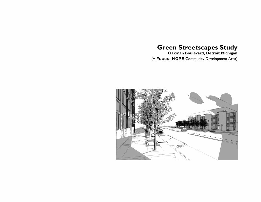
Green Streetscapes StudyOakman Boulevard, Detroit Michigan
(A Focus: HOPE Community Development Area)

Prepared for:
U.S. Environmental Protection Agency
Office of Solid Waste and Emergency Response
Office of Brownfields and Land Revitalization
Washington, DC 20460
Prepared by:
Tetra Tech Architects & Engineers
215 The Commons
Ithaca, NY 14850
SRA International, Inc. (Contract No. EP-W-07-023)
3434 Washington Boulevard
Arlington, VA 22201

Table of Contents
1. INTRODUCTION.................................................... 1
1.1. What is the Purpose of the Study?.........................................1
1.2. How to Use This Document ...................................................1
2. “GREEN” STREETSCAPES DESIGN
OBJECTIVES.................................................................... 3
2.1. Improve Air Quality ...................................................................3
2.2. Reduce Heat Island Effects .......................................................4
2.3. Improve Water Quality.............................................................5
2.4. Enhance the Urban Forest and Wildlife Habitat .................6
2.5. Mitigate/Rehabilitate Brownfield
Conditions ...................................................................................................7
3. “GREEN” STREETSCAPE DESIGN
STANDARDS.................................................................10
3.1. Streetscape Geometry ........................................................... 11
3.2. Paving Materials ........................................................................ 12
3.3. Stormwater Management Facilities (SMFs)........................ 15
3.4. Landscaping ............................................................................... 20 3.5. Furniture and Fixtures ............................................................ 22 3.6. Bicycle Facilities........................................................................ 24
4. APPLYING THE GUIDELINES............................25
5. OAKMAN BOULEVARD “GREEN”
STREETSCAPE CONCEPT .........................................26
5.1. Site Analyis ................................................................................ 26
5.2. Existing Conditions.................................................................. 27
5.3. Conceptual Design .................................................................. 28
5.4. Future Bike Lanes and Intersection Improvements .........34
5.5. Crosswalk Design.....................................................................37
6. APPENDIX..............................................................39
6.1. Construction Details ...............................................................39
6.2. Bioretention Basin Soil Specification ...................................40
6.3. Recommended Plant Lists ......................................................43
6.4. SMF Maintenance Guidelines.................................................47
6.5. Streetscape SMF Sizing Guide ...............................................48
6.6. Potential LEED credits in Streetscape Development ......51
1. INTRODUCTION
1.1. What is the Purpose of the Study?
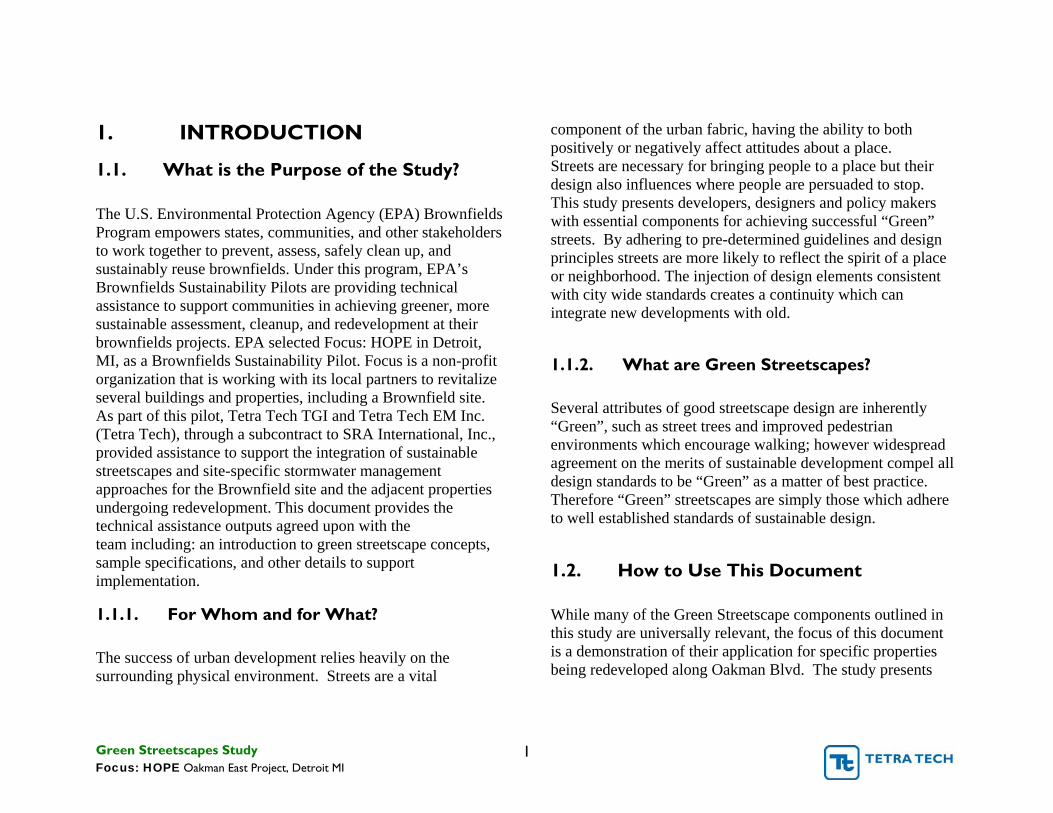
The U.S. Environmental Protection Agency (EPA) Brownfields Program empowers states, communities, and other stakeholders to work together to prevent, assess, safely clean up, and sustainably reuse brownfields. Under this program, EPA’s Brownfields Sustainability Pilots are providing technical assistance to support communities in achieving greener, more sustainable assessment, cleanup, and redevelopment at their brownfields projects. EPA selected Focus: HOPE in Detroit, MI, as a Brownfields Sustainability Pilot. Focus is a non-profit organization that is working with its local partners to revitalize several buildings and properties, including a Brownfield site. As part of this pilot, Tetra Tech TGI and Tetra Tech EM Inc. (Tetra Tech), through a subcontract to SRA International, Inc., provided assistance to support the integration of sustainable streetscapes and site-specific stormwater management approaches for the Brownfield site and the adjacent properties undergoing redevelopment. This document provides the technical assistance outputs agreed upon with the team including: an introduction to green streetscape concepts, sample specifications, and other details to support implementation.
1.1.1. For Whom and for What?
The success of urban development relies heavily on the surrounding physical environment. Streets are a vital
component of the urban fabric, having the ability to both positively or negatively affect attitudes about a place. Streets are necessary for bringing people to a place but their design also influences where people are persuaded to stop. This study presents developers, designers and policy makers with essential components for achieving successful “Green” streets. By adhering to pre-determined guidelines and design principles streets are more likely to reflect the spirit of a place or neighborhood. The injection of design elements consistent with city wide standards creates a continuity which can integrate new developments with old.
1.1.2. What are Green Streetscapes?
Several attributes of good streetscape design are inherently “Green”, such as street trees and improved pedestrian environments which encourage walking; however widespread agreement on the merits of sustainable development compel all design standards to be “Green” as a matter of best practice. Therefore “Green” streetscapes are simply those which adhere to well established standards of sustainable design.
1.2. How to Use This Document
While many of the Green Streetscape components outlined in this study are universally relevant, the focus of this document is a demonstration of their application for specific properties being redeveloped along Oakman Blvd. The study presents
Green Streetscapes Study 1 Focus: HOPE Oakman East Project, Detroit MI

seven essential “Green Streetscape Design Objectives” which are described in Chapter 2. All “Green” streetscape designs should include elements which meet each of the design objectives. Chapter 3 describes a series of design components or “Streetscape Standards”. These standards are detailed descriptions or examples of streetscape elements which a designer may use to achieve the objectives set out in Chapter 2. Chapter 4 provides a matrix which illustrates design standards that meet the various design objectives. Filling in a similar matrix is a good exercise for establishing a project’s scope early on in the design process. Chapter 5 puts the “Streetscape Standards” into practice by demonstrating their application to redevelopment efforts along Oakman East in Detroit’s Central Woodward/ North End. A conceptual design for Oakman Blvd includes specific construction details for the site area where the planned redevelopment meets the street, taking environmental conditions of the property into consideration. The resulting stormwater management and streetscape designs become a prototype for other streetscapes in the area or streets elsewhere that reside within similar contexts. Chapter 6 contains option specific details, technical specifications, and other information which can help designers begin to develop construction documents for implementation within the Focus: HOPE, Oakman East redevelopment area.
Green Streetscapes Study 2 Focus: HOPE Oakman East Project, Detroit MI
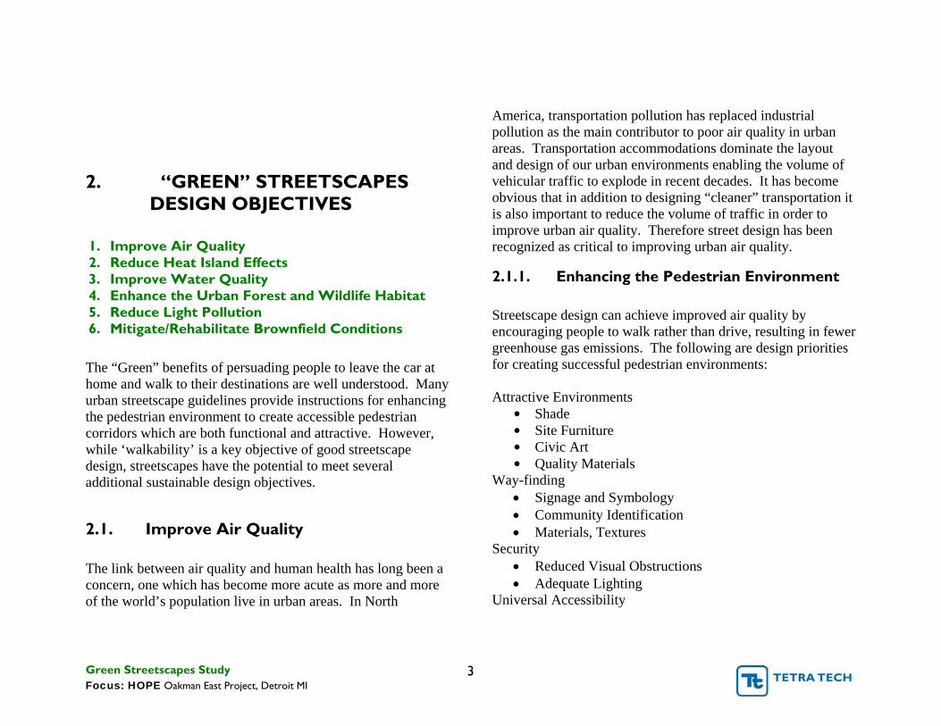
2. “GREEN” STREETSCAPES DESIGN OBJECTIVES
1. Improve Air Quality 2. Reduce Heat Island Effects 3. Improve Water Quality 4. Enhance the Urban Forest and Wildlife Habitat 5. Reduce Light Pollution 6. Mitigate/Rehabilitate Brownfield Conditions
The “Green” benefits of persuading people to leave the car at home and walk to their destinations are well understood. Many urban streetscape guidelines provide instructions for enhancing the pedestrian environment to create accessible pedestrian corridors which are both functional and attractive. However, while ‘walkability’ is a key objective of good streetscape design, streetscapes have the potential to meet several additional sustainable design objectives.
2.1. Improve Air Quality
The link between air quality and human health has long been a concern, one which has become more acute as more and more of the world’s population live in urban areas. In North
America, transportation pollution has replaced industrial pollution as the main contributor to poor air quality in urban areas. Transportation accommodations dominate the layout and design of our urban environments enabling the volume of vehicular traffic to explode in recent decades. It has become obvious that in addition to designing “cleaner” transportation it is also important to reduce the volume of traffic in order to improve urban air quality. Therefore street design has been recognized as critical to improving urban air quality.
2.1.1. Enhancing the Pedestrian Environment
Streetscape design can achieve improved air quality by encouraging people to walk rather than drive, resulting in fewer greenhouse gas emissions. The following are design priorities for creating successful pedestrian environments:
Attractive Environments • Shade • Site Furniture • Civic Art • Quality Materials
Way-finding • Signage and Symbology • Community Identification • Materials, Textures
Security • Reduced Visual Obstructions • Adequate Lighting
Universal Accessibility
Green Streetscapes Study 3 Focus: HOPE Oakman East Project, Detroit MI

• Barrier Free • Urban Braille (textural cues for the blind)
2.1.2. Street Trees Street trees are important streetscape elements which serve to meet several “Green” Streetscape design objectives including improving air quality. In the article “Urban Street Trees, 22 Benefits”, Dan Burden lists several of these qualities:
• Automobile emissions. Street trees can significantly reduce the impact of automobile emissions including carbon monoxide (CO), volatile organic compounds (VOC), nitrogen oxides (NOx), and particulate matter (PM).
• Gas transformation efficiency. Street trees within the city absorb 9 times more pollutants than trees outside the city, converting harmful gases back into oxygen and other useful and natural gases.
• Lower Ozone. The combination of the higher urban street temperatures and tailpipe emissions dramatically increase the conversion of harmful ozone and other gases into more noxious substances that have an adverse effect on human health. Street trees lower temperatures and thereby help lower ozone generation.
2.2. Reduce Heat Island Effects
Temperatures in urban areas are often several degrees warmer than the rural surrounding area especially during the hot
summer months. Acres of urban asphalt and concrete pavement which comprise city streets contribute to this condition. The higher air temperatures cause:
• Increased energy consumption as air conditioners are employed to cool indoor spaces.
• Elevated emissions of air pollutants and greenhouse gases.
• Compromised human health and comfort. • Impaired water quality: warm stormwater runoff raises
downstream temperatures with detrimental effects on aquatic flora and fauna.
2.2.1. Street Trees
Street trees are capable of significantly lowering urban air temperatures. Where street trees create a continuous overhead canopy, temperature differentials of 5-15 degrees are felt. However, human comfort is not the only benefit of shady streets. Well shaded streets also shade homes and create a cooler microclimate around them which can reduce household energy bills from 15-35%.
2.2.2. Designing “Cool” Streets
Conventional asphalt pavements can reach peak summertime surface temperatures of 120–150°F. The properties of conventional pavements, particularly black asphalt also make them very effective at storing heat. During the summer these
Green Streetscapes Study 4 Focus: HOPE Oakman East Project, Detroit MI

pavements release heat throughout the night time. Using light colored pavements which reflect more solar energy results in cooler paved environments. According to the EPA’s document, Reducing Urban Heat Islands, light gray and tan colors can reduce pavement surface temperatures by 20 to 40°F (11°C to 22°C). Porous pavement can also be cooler as water is retained as it passes through the pavement.
Asphalt options for reducing heat island effect include:
• Open graded asphalt surfaces on top of dense
pavements
• Porous pavement systems • Light colored pavements, which incorporate:
o Light colored aggregates (which increase solar reflectance)
o Synthetic binders (which can be any color) o Durable surface coatings applied to the asphalt
surface o Light-colored resin modifiers
Other paving materials which can reduce the Heat Island Effect through increased solar reflectance or water retention are:
• Standard Portland concrete (some pigments can further improve solar reflectance)
• Porous block pavement systems (water retention and increased solar reflectance)
• Plastic grid pavement systems (water retention)
• Certain light colored brick pavers (increased solar reflectance)
2.3. Improve Water Quality Streets are one the largest sources of Nonpoint Source Pollution. This section describes issues concerning urban stormwater management and how various streetscapes features can help mitigate a city’s negative impact on water quality.
2.3.1. Stormwater Management
The National Pollutant Discharge Elimination System (NPDES) permit program controls water pollution by regulating sources which discharge pollutants directly to waters of the United Sates. The goal of the program is to limit pollutants associated with industrial waste water and non-point stormwater from discharging to natural water bodies. As regulations become more and more stringent, civil engineers and landscape architects have developed innovative methods for meeting the regulations in ways that are more cost effective and aesthetically pleasing. Stormwater management facilities act to filter out pollutants from runoff, detain water to reduce flooding and limit erosive conditions downstream, and infiltrate stormwater to recharge groundwater and aquifers. Where streets are concerned, stormwater experts have recognized that managing stormwater locally can reduce the runoff reaching downstream facilities and have dramatic effect on the size and cost of those measures. A “Green” street design endeavors to provide as many opportunities to detain, filter and
Green Streetscapes Study 5 Focus: HOPE Oakman East Project, Detroit MI

infiltrate stormwater as possible and do it in a manner which creates an esthetic interest for the streetscape.
2.3.2. Combined Sewer Overflows (CSOs) which combine stormwater and sanitary sewers are a serious contributor to water pollution. When heavy rainfall events occur, the water volume in a combined sewer can overwhelm the pipe network and sewage treatment plants, spilling sewage into local streams and rivers. The Clean Water Act requires that communities dramatically reduce or eliminate their combined sewer overflows. Some cities have constructed costly underground stormwater storage facilities to reduce the flow of water to their treatment facilities so that they are not overwhelmed and sewage doesn’t overflow the system before being treated. Installing rain gardens, permeable pavements, roof gardens, blue roofs, or even grassy swales or ditches along roadways can help to reduce the volume of stormwater taxing sewer systems. Diverting stormwater to these types of mostly low tech and cost effective facilities diminishes flows to the sewers and allows soil and vegetation to filter runoff while groundwater supplies are replenished.
2.3.3. Street Trees Street trees can allow site designers to use less drainage infrastructure. Trees use and transpire back to the air a significant percentage of the rain which falls on and near them; this reduces stormwater volumes. The first 30% of most precipitation is absorbed through its leaf system, allowing evaporation back into the atmosphere. An additional percentage (up to 30%) of precipitation is absorbed back into
the ground, retained and absorbed by the root structure, and then transpired back to the air. Any water that is not ultimately taken up by the tree will naturally percolate into the ground to recharge the groundwater and aquifers.
2.4. Enhance the Urban Forest and Wildlife Habitat Paved surfaces account for 30-45% of land cover in urban areas with buildings accounting for much of the remaining surface area. With this in mind it becomes clear that landscaping street right-of-ways and medians is critical to creating a sustainable urban forest. Street vegetation can provide habitat and food for wildlife as well as places to rest, hide and move through. Streets trees can create “green” links or corridors between urban open spaces. Connectivity between larger parks and preserves increases the habitat value of the urban forest.
2.4.1. Reduce Light Pollution Pedestrian safety and nighttime aesthetics often seem to be at odds with anti-light pollution standards. Sustainable Streetscape design must balance public safety and comfort with efficient, minimalist and non-polluting lighting.
2.4.2. Dark Sky Standards To the maximum extent possible, lighting should be low intensity and conform to "Dark Sky" standards of downward projected, "full cut-off" illumination that shields light from being emitted upwards toward the night sky or surrounding
Green Streetscapes Study 6 Focus: HOPE Oakman East Project, Detroit MI

natural areas. To be full cut-off, the light bulb should not extend below the lamp shade.
2.5. Mitigate/Rehabilitate Brownfield Conditions Sites where previous land use has complicated expansion, redevelopment or reuse because of the presence or potential presence of toxic residue are referred to as Brownfields. Special design consideration must be given to some streetscape elements where they are installed over Brownfield sites. Brownfields soils may include contaminants that must be removed or managed to prevent risks to human health and the environment. Stormwater management facilities must be carefully designed to prevent exacerbation of the existing contaminated condition. Stormwater management facilities are beneficial however, where they can prevent runoff from flowing onto nearby contaminated areas as this diminishes the leaching of contaminants into the groundwater which may be occurring under existing conditions.
2.5.1. General Guidelines to Brownfield Design Designs for developing Brownfield sites should only be done by qualified and experienced site designers. The following bullets provide information that organizations planning on developing Brownfield sites should be aware of:
• Ideally site remediation is completed before, or done in conjunction with, site redevelopment.
• Understand the contamination on site, the extent of the location(s) of contamination, the maximum
concentrations of the contaminants, and the risks associated with the contamination remaining in place. Testing should be performed by a qualified testing agency.
• When the contaminants on a site pose a threat to human health and the environment, the development proposal must first go through a due care review process mandated by the Michigan Department of Environmental Quality.
• Careful attention must be paid to redevelopment work occurring where soil remediation has occurred, particularly where utility trenches are being cut. Utility trenches become preferred pathways for contaminants as the free draining bedding material can flow contaminated water from a contained area to new unspoiled locations.
• Actions that cause contamination to migrate beyond the source property boundaries at levels above cleanup criteria are considered “exacerbation.” Consequences associated with exacerbation of existing conditions are identified and enforced under Michigan’s cleanup programs.
The following page identifies some more specific guidelines for Brownfield development specifically in the state of Michigan.
Green Streetscapes Study 7 Focus: HOPE Oakman East Project, Detroit MI

The University of Michigan’s School of Natural Resources and Environment developed the following design guidelines as part of a planning project that used low impact development (LID) techniques on contaminated sites. The following guidelines were reviewed and adapted by the Michigan Department of Environmental Quality for their “LID Manual for Michigan.”
• Avoid infiltration practices in contaminated areas. If infiltration is proposed and contaminated areas cannot be avoided, additional testing could demonstrate that residual contamination will not leach from the percolation of rainfall through the contaminated soils to groundwater in concentrations that present an unacceptable risk. If leach testing demonstrates infiltration would result in additional unacceptable concentrations reaching the groundwater, design considerations to separate contaminated soils from contact with stormwater must be included.
• LID practices on brownfield sites may include treatment and storage with reuse of stormwater rather than complete infiltration. Most brownfields that have residual contamination need caps, so vegetated areas need to be located above caps and fitted with underdrain systems to remove stormwater or reservoirs to capture it for later use.
• Detention, retention, and biofiltration are suitable for contaminated sites when designed to prevent exfiltration to underlying soils and allow adequate time
for water to be in contact with plants and trees for bioremediation. Infiltration trenches and basins collect stormwater and infiltrate or attenuate runoff. If fitted with filter devices for pre-treatment of contaminated water, these become wastewater treatment systems subject to requirements of NPDES permits.
• Permeable pavement and rain gardens are not usually suitable for sites with residual contamination that could be mobilized to groundwater, or to the storm sewer system in cases where these structures are underdrained. Additional features including impermeable liners can be coupled with modified LID practices to safely filter and manage stormwater without exposing the water to contaminated soils.
• Retain/revegetate trees and vegetation. Retaining and revegetating helps evapotranspirate stormwater runoff while intercepting large amounts of rainfall that would otherwise enter waterways as runoff.
• Use impervious surfaces as additional caps. When siting the development, consider locating buildings and other impervious surfaces over contaminated areas as long as escaping vapors or other contaminants are not present or are controlled to prevent health risks. For example, one could strategically locate a parking area over a small, contaminated area.
• Implement practices that encourage evapotranspiration and capture/reuse water. Green roofs are an ideal way
Green Streetscapes Study 8 Focus: HOPE Oakman East Project, Detroit MI

to reduce runoff from building roofs by encouraging evapotranspiration of rainwater. Another option for brownfield sites is to capture and reuse stormwater for non-potable uses. This can include runoff storage in rain barrels for irrigation of green roofs or landscaped areas, or in cisterns that store rainwater for toilet flushing and other uses.
• Include LID techniques in sites around brownfield areas. New and redeveloped sites near brownfields should use green infrastructure practices to prevent additional runoff from flowing onto potentially contaminated areas.
Green Streetscapes Study 9 Focus: HOPE Oakman East Project, Detroit MI

X X X X X X X X
Travel Lanes Travel Lanes
X
3. “GREEN” STREETSCAPE LandscapeDESIGN STANDARDS
Paving MaterialsDesign standards are specific guidelines and details for landscape features which can make up a streetscape design. This section will illustrate general standards for streetscape Stormwater Management layout and detail those landscape features which are best suited to achieving the “Green” design objectives.
Furniture and Fixtures
Planter Walkway Street tree Median Landscape Street tree Walkway strip Bike Lane Bike Lane Area strip
Car Parking Car Parking
Anatomy of a Green Streetscape
Green Streetscapes Study 10 Focus: HOPE Oakman East Project, Detroit MI

3.1. Streetscape Geometry
Whether you are designing a new pedestrian environment for an existing street, redeveloping an entire right of way or designing a brand new street, the first step is to establish the geometry. City and municipal traffic engineering departments have standards for major street alignments and planning documents may describe land use and street hierarchies. Project engineers, architects and landscape architects will synthesize all of the controlling factors to create a design that is safe, functional and appealing. Green streetscapes require an even higher level of coordination between project designers and municipal representatives. Variances are often required to meet some “Green” street design objectives as they require geometries and utility solutions which don’t meet the established planning ordinances or engineering standards. For example, conflicts commonly arise when pavement reductions to reduce impervious surfaces are proposed because standards for travel lane widths and zoning ordinance parking formulas establish default street widths. These types of conflicts can better be identified and addressed through early planning and communication between all interest groups to establish a common vision of the project goals and objectives.
Green Objectives
• Use minimum travel lane widths where possible to reduce impervious surface area.
• Provide linear opportunities for street tree plantings.
• Utilize traffic calming for slow speed streets – narrow lanes, curb bump-outs and center median pedestrian refuge.
• Provide opportunities for alternative transportation, including public transit and bicycling.
• Create walkable streets – accessible, unobstructed pedestrian corridors.
Green Streetscapes Study 11 Focus: HOPE Oakman East Project, Detroit MI

3.2. Paving Materials
Pavement is an essential component of any streetscape but it is often overlooked as a feature. If a street appears “generic” or un-memorable you
probably don’t even think about the paving materials unless they are in very poor condition. Uniquely paved streetscapes which break the monotony of the ubiquitous grey surfaces we see daily can elevate our impression of a place. Consequently, the vast palette of available paving materials becomes an important tool in the streetscape designer’s toolbox. Many paving materials are available in different colors, patterns and textures which add visual interest to a street. However, of particular importance to the objective of these guidelines are their sustainable attributes. Paving materials may be selected for reflectivity, green manufacturing, local sourcing and permeability.
Green Objectives
• Use permeable paving where appropriate to reduce stormwater runoff and allow for groundwater recharge.
• Use “Cool Pavements” wherever possible to reduce the Urban Heat Island Effect.
• Use locally sourced paving materials manufactured with sustainable practices to reduce life-cycle environmental impacts.
Pervious Pavements • Are increasingly being recognized by regulators as
structural stormwater Best Management Practices (BMPs).
• Stormwater runoff is significantly reduced, infiltration for ground water recharge is increased
• Roof leaders may be connected to storage beds below pervious pavements, reducing on-site stormwater volume requirements
• The initial cost of permeable pavement may be higher than conventional, impermeable technologies, but these costs are often offset by savings from reduced requirements for grading, treatment ponds, or other drainage features, such as inlets and stormwater pipes (EPA: Reducing Stormwater Costs)
• Where communities have combined sewers, there could be environmental, social, and cost benefits from reducing combined sewer overflows, as well as potentially avoiding part of the increased infrastructure costs associated with combined sewer operation. (EPA: Reducing Stormwater Costs)
Green Streetscapes Study 12 Focus: HOPE Oakman East Project, Detroit MI

Porous Asphalt Porous Asphalt is a flexible pavement which allows water to flow through it rather than over it as water does with traditional asphalt. Like traditional asphalt pavement, porous asphalt is a bituminous substance derived from crude oil which binds together select stone aggregates and sand to form a durable wear layout over a stone base. Porous asphalt achieves its porosity by eliminating the fine particles from its mix specification.
Pervious Concrete Pervious Concrete achieves porosity by reducing the amount of fines in the mix just like Porous Asphalt. The voids in the concrete pavement give the surface a much coarser appearance compared to standard impervious concrete. The low mortar content and increased void space reduces strength compared to standard concrete however sufficient strength is achieved for all but heavy duty applications. Pervious concrete is not suitable for high traffic roadways.
Green Streetscapes Study 13 Focus: HOPE Oakman East Project, Detroit MI

Permeable Paver Blocks Permeable Paver Blocks are manufactured units which interlock to create a durable pavement. Designs vary but all permeable systems leave surface void spaces which are filled with permeable materials such as pea gravel, sand or soil, allowing surface water to infiltrate.
Permeable Paving Do’s and Don’ts
• Shouldn’t be used on slopes of more than 5% • In areas with poorly draining soils, infiltration beds
below pervious pavements may be designed to slowly discharge to adjacent bioretention areas.
• Provide a backup method for water to enter the storage bed in the event of pavement failure.
• Infiltration beds should have level bottoms. • Should not be placed on recent fill or compacted fill
less than 5 yrs old as the infiltrated water could destabilize the fill.
• Soil infiltration tests are required to ensure adequate infiltration rates and for sizing storage beds.
Green Streetscapes Study 14 Focus: HOPE Oakman East Project, Detroit MI

3.3. Stormwater Management Facilities (SMFs)
Traditionally, streets have not been considered part of the stormwater management solution in civil design. In fact, the impervious surfaces which make up our
streets create stormwater runoff and civil designers typically utilize underground infrastructure to whisk the water away so that it doesn’t pond and flood our cities. Only recently have designers and engineers considered using streetscape elements to help deal with rainwater where it lands. Today streetscape designers can utilize many innovative stormwater management techniques designed not only to store and/or infiltrate stormwater but also to filter out pollutants to improve water quality before water makes its way to aquifers, streams and lakes.
Green Objectives
• Improve water quality by filtering out
Nonpoint Source Pollution.
• Reduce the load on Combined Sewer
Overflows by reducing stormwater
runoff volumes entering the sewer
system.
• Infiltrate stormwater for groundwater and aquifer recharge, wherever
possible.
Green Streetscapes Study 15 Focus: HOPE Oakman East Project, Detroit MI
3.3.1. Constructed Filter
When space does not permit the use of above ground stormwater management facilities such as Stormwater Planters or Rain Gardens, Constructed Filters are useful water quality treatment facilities. These structures are excavated areas backfilled with a filter media composed of a layer of sand, compost, organic material, peat, or other media. This filter media is designed to filter out pollutants such as sediments, metals, and hydrocarbons, from stormwater runoff.
Filter Example There are many filter designs. The digram below illustrates a small filter ideal for hot spot pretreatment particularly useful where you may have a known pollutant source that needs to be reduced before stormwater enters subsequent stormwater facilities.
Source: Pennsylvania Stormwater BMP Manual

3.3.2. Bio-Retention Facilities Bio-Retention facilities utilize biological processes for the removal of stormwater run-off pollutants. These facilities can range in appearance from created wetlands to hardscape features which are designed to mimic natural bioremediation processes. Although physical appearances may vary dramatically from facility to facility, they all contain growing media and vegetation. As water pools in the facility it infiltrates through the growing media and is filtered. Site soil conditions dictate the final stage in the bio-retention facility. Where soils are free draining and not contaminated, water can be allowed to completely infiltrate for groundwater re-charge. Where soils are poorly drained the facility will include gravel beds and underdrains to move water from the facility in the event of heavier rain events.
Bio-Retention System Components • Pretreatment • Flow Inlet • Ponding Area • Plant Material • Organic Layer or Mulch • Planting Soil/volume Storage Bed • Positive Overflow
Stormwater Planters Stormwater Planters receive runoff from multiple impervious surfaces. This runoff is used to irrigate the vegetation in the planter and prevents stormwater from directly draining into
nearby sewers. Stormwater Planters also play an important role in urban areas by minimizing stormwater runoff, reducing water pollution, and creating a greener and healthier appearance of the built environment by providing space for plants and trees near buildings and along streets. There are three main types of stormwater planters which can be used on sidewalks, plazas, rooftops, and other impervious areas: contained, infiltration, and flow-through. Where Stormwater Planters are constructed over contaminated soils they will be “contained” type facilities which include impervious bottoms or liners to ensure pollutants do not leach into the groundwater. The primary function of contained facilities is filtration, although there is some volume reduction through evaporation and transpiration. The following page provides examples of Stormwater Planter applications.
Flow-Through Stormwater Planter
Stormwater Runoff
Stormwater VegetationRunoff
From Roadway
Organic Layer or Mulch
Planting soilFlow Inlet Volume
Storage Bed
See Appendix 7.1 for Positive Overflow Construction Details
Green Streetscapes Study 16 Focus: HOPE Oakman East Project, Detroit MI

Michigan Avenue rain gardens in planter boxes in Lansing, MI. Cultural Trail Indianapolis: Median Stormwater Planter Source: Tetra Tech Photo Credit: indyculturaltrail.org/blog/tag/green-street/
Sidewalk Stormwater Planter Photo Credit: www.tavelladesigngroup.com
Street view of rain gardens in planter boxes in Lansing, MI. Source: Tetra Tech
Green Streetscapes Study 17 Focus: HOPE Oakman East Project, Detroit MI

Rain Gardens Rain Gardens are stormwater management facilities for storage and infiltration of relatively small volumes of stormwater. Rain Gardens are not well suited to highly urban conditions, but they are useful in residential settings and even more dense residential complex developments. A Rain Garden is established by creating a depression or shallow pond which receives rainwater from adjacent streets, sidewalks, parking lots and roofs. The depression is planted with flood tolerant vegetation which contributes to filtering pollutants from stormwater runoff. Water which infiltrates the planting soil is also filtered and in some cases stored to reduce peak flows. Positive overflow systems are installed to prevent flooding around the garden during larger storm events. Rain Gardens, like other bioretention facilities are best suited for areas with infiltration rates of more than 0.25 inches per hour.
• When considering infiltration type stormwater management facilities always perform the appropriate soil infiltration tests.
• Refer to the LID Manual for Michigan, Appendix E “Soil Infiltration Testing Protocol”.
• For Brownfields properties, refer to pages 7 and 8 of this document, however, Rain Gardens are not generally recommended for sites with contaminated soils.
Source: Prince George’s County Bioretention Manual with modifications by Cahill Associates, 2004
Green Streetscapes Study 18 Focus: HOPE Oakman East Project, Detroit MI

3.3.3. Bio-Filtration Facilities
Bio-Filtration is a system which uses living material to capture and/ degrade pollutants carried by stormwater runoff. These facilities are often used to improve stormwater quality before it enters retention or infiltration facilities. Bio-filtration facilities are particularly useful for streetscaping as pre-treatment for pollution and are typically most useful adjacent to streets. The physical design is narrow and linear allowing them to fit in medians or street right-of-way spaces. Bio-filtration facilities include grass filter strips which are gently sloped grassy areas typically used to treat sheet flow and vegetated swales or “Bioswales” which are described below.
Bioswales
Bioswales are the Bio-filtration Facilities best suited to streetscape design. They are designed as long, shallow earthen channels planted with native wildflowers, grasses, shrubs and trees designed to slow, filter and infiltrate stormwater runoff. As stormwater flows slowly along the swale, plants take up various pollutants while still more water is filtered as it infiltrates through the soil. Swales should be between 200 and 250’ long in order to retain water long enough to allow filtration to occur. Underdrains placed below the planting soil prevent standing water from occurring. Bioswales can be stand alone stormwater facilities or pretreatment devices for stormwater being conveyed to larger downstream facilities.
Photo Credit: www.glencoe.pps.k12.or.us
See Appendix 7.1 for Construction Details
Existing Subgrade
Perforated Underdrain
Planting Media
Sidewalk
Street
Bioswale
Green Streetscapes Study 19 Focus: HOPE Oakman East Project, Detroit MI

3.4. Landscaping
Trees and plantings are critical elements of streetscape design. Trees define a street and separate traffic from pedestrians. Their canopies can
give streets a “ceiling”, scaling down what might otherwise be overpowering environments. Trees soften harsh urban environments and can improve spaces where the architecture has little to offer. Street landscaping ensures that people remain connected to nature despite the urban setting. The many environmental benefits to street trees and plantings were discussed earlier in this study and are summarized below.
Photo credit: www.cnr.vt.edu/urbanforestry
Green Objectives
• Positively influence localized climate (shade from summer sun and shelter from winter winds).
• Remove air pollutants. • Increase animal habitat. • Reduce stormwater runoff. • Reduce heat and associated energy
use for cooling. • Encourage use by improving the
pedestrian environment.
Photo credit: www.fs.fed.us
Green Streetscapes Study 20 Focus: HOPE Oakman East Project, Detroit MI

3.4.1. Street Trees and Structural Soils Streets are extremely harsh environments for trees. According to the American Forestry Association the average life of a downtown street tree is only 13 years. Air pollution, compacted soils, drought conditions, contaminated water, lack of root space and many other factors all contribute to this statistic. In light of the poor environmental conditions in which street trees exist it is vital to tree health that they are planted where proper root structure can develop in soil with adequate water, nutrients and oxygen. Street trees are typically planted in sidewalks or narrow medians where roots quickly encounter adverse soil conditions as they attempt to spread under the paved surfaces. “Structural Soils” are an engineered growing medium designed to address soil compaction and a lack of useable soil volume where trees are planted in pavement. In street tree plantings, structural soils ideally extend from the curb to the building face under the entire pedestrian zone to allow for tree roots to extend as far as possible. The composition of the structural soil ensures that even under heavily used pavements it never becomes so compacted that roots cannot grow into the pore spaces. Structural soil can be expensive; however, it is a relatively small price to pay for tree longevity and the added insurance that trees will reach maturity and the ultimate vision of the streetscape design is realized.
See Appendix 7.1 for Construction Details
Green Streetscapes Study 21 Focus: HOPE Oakman East Project, Detroit MI

3.5. Furniture and Fixtures 4. Furniture siting should consider the local demographic. For example, if the local population is elderly try to place benches every 200 feet as resting stops. Site Furniture and Fixtures such as street lights or
5. Place site furniture in its own zone along walkways to bollards can enhance the pedestrian environment by maintain an unobstructed walking corridor. providing rest, convenience, utility and safety. They
6. Do not place furniture at street corners where it may are specified for most streetscapes however it is important that interfere with sight lines.designers choose site furniture and fixtures which meet their
7. Select furniture within a product range, having shared overall “Green” streetscape objectives. design elements which express a holistic design approach.Green Objectives
8. To avoid the appearance of a cluttered streetscape, attempt to create a pattern or rhythm with the furniture • Create comfortable outdoor spaces which elements. encourage people to walk rather than drive. 9. Choose sturdy, vandal resistant and sustainable• Reduce light pollution while maintaining a materials. safe pedestrian environment.
• Use locally produced, recycled and/or
renewable materials and energy efficient
products wherever possible.
Furniture Siting Guidelines
1. Place appropriate furniture according to the
requirements of a particular space. For example, provide seating and a trash bin near a coffee shop.
2. Locate sitting areas to take advantage of winter sun and
Summer shade.
3. Group street furniture to create a sense of place at
potential gathering points.
Photo credit: www.class.uidaho.edu/.../sidewalks.htm
Green Streetscapes Study 22 Focus: HOPE Oakman East Project, Detroit MI

3.5.1. Outdoor Lighting
Well designed outdoor lighting will contribute to creating green streets and neighborhoods and enhance safety and security. Careful design can reduce negative environmental impacts of outdoor lighting by:
• reducing energy use by focusing lighting to where it is needed;
• reducing energy use by utilizing energy efficient luminaires such as LED or solar powered street lights;
• reducing energy use by utilizing light network control systems which eliminate unnecessary light operation;
• minimizing obtrusive light, also known as glare, which can cause annoyance, discomfort or loss of visual ability for pedestrians and drivers and intrude into interior living spaces;
• minimizing light spillage onto adjacent properties or into residences;
• minimizing the upward casting of light into the night sky that in many cities has blotted out all but the brightest stars.
Design elements that meet the objective of providing safety and security, while minimizing impacts, include:
• shielded luminaires that protect pedestrians and
motorists from obtrusive light;
• high cut-off fixture designs that minimize light spillage by directing light only to where it is needed;
• fully shielded fixtures that eliminate the upward cast of light into the sky above the fixture.
Integrating these elements into the design of outdoor lighting will provide the sense of security that urban resident’s desire. At the same time they will create a more attractive nighttime living environment for pedestrians, drivers and residents by reducing the negative impacts of light pollution.
Photo credit: www.inhabitat.com
Cutoff lighting limits light pollution of the sky and directs light only where it’s needed.
Green Streetscapes Study 23 Focus: HOPE Oakman East Project, Detroit MI

3.6. Bicycle Facilities
Designing green streets includes identifying needs and accommodating bicycles just as for other vehicles in the traffic mix. Streets should be designed and constructed to safely accommodate known and anticipated bicycle traffic and encourage bicycle use. The fundamental needs of bicyclists are twofold: safety while moving in traffic and convenient, safe and secure parking.
All streets on which bicycles are permitted to operate should be designed and maintained to accommodate shared use by bicycles and motor vehicles. On most urban streets safety while moving in traffic can be accomplished with wide lanes (4.5M/14.67ft) or with dedicated bike lanes on higher volume, higher speed arterials.
Integrating signs and pavement markings for bicycle facilities into the design of the street can encourage increased bicycle use. Signs and pavement markings can improve traffic operations as well as increase safety by alerting drivers to the presence of bicycles. This helps legitimize the presence of bicycles in the eyes of motorists, and encourage bicycle use.
Conveniently located, safe and secure parking should be provided as part of an overall traffic plan and street design. Integrating an adequate number of appropriately designed bike racks within or adjacent to other transportation facilities, such as parking garages and bus stops, is a cost effective approach.
Green Streetscapes Study 24 Focus: HOPE Oakman East Project, Detroit MI
Bicycle racks under cover, for instance within a parking structure, will encourage bicycling in inclement weather as well as good weather.
Critical to promoting safe bicycling is ensuring that bike lanes and street gutters are clear of debris. Loose stone, deicing sand and grit, litter and debris from passing traffic can be a major hazard to bicyclists moving in traffic. Failed pavement and sunken storm grates can also create hazards to bicyclists.

4. Applying the Guidelines The table below provides a crosswalk of the design objectives discussed in Chapter 2 and the Streetscape elements presented in Chapter 3. The chart is a simple tool for identifying combinations of streetscape elements which will ensure that all 7 Green Streetscape Design Objectives are met.
Stre
etsc
ape
Ele
men
ts
7 Green Streetscape Design Objectives Improve Air
Quality Reduce
Heat Island Effects
Improve Water
Quality/ Efficiency
Improve Energy
Efficiency
Enhance the Urban Forest
& Wildlife Habitat
Reduce Light
Pollution
Mitigate/ Rehabilitate Brownfield Conditions
Porous Paving D DLight colored Paving D DLandscaping D D DPlanters D D DBicycle Rack DStormwater Planters D D D DBio-Swale D D D DConstructed Filters DRain Gardens D D DRecycling Bins DStreet Trees D D D D DContinuous Planting Strips D D DCut-off lighting D DNarrow Lanes D DBicycle Lanes D D
Green Streetscapes Study 25 Focus: HOPE Oakman East Project, Detroit MI

5. Oakman Boulevard “Green” Streetscape Concept
This Chapter presents a conceptual streetscape design for adjacent redevelopment sites along Oakman Blvd in Detroit, MI. The design is intended to illustrate the feasibility of meeting the 7 “Green” Streetscape objectives previously outlined in this study and provide a roadmap for implementation at this location.
infrastructure is also present. The following page provides a5.1. Site Analyis plan of the existing underground and overhead utilities. The study site includes a half block of Oakman Blvd. at Woodrow Wilson Ave. located in Detroit’s Central Woodward/ North end area. A new pocket park has recently been constructed at the corner of Oakman Blvd. and Woodrow Wilson Ave. providing a much needed open space amenity for the neighborhood. A historic commercial high rise building on the north side of Oakman Blvd. is to be converted to a mixed use building while a three story residential complex is planned for a site on the south side of the street. All new construction proposed for these sites is designed with sustainability in mind and there is an excellent opportunity to extend these “green” design principles to area where the properties meet the street and into the design of the street itself. Oakman Blvd. is an arterial street with a 120’ right of way. The street is configured with two travel lanes in each direction as well as parking lanes on either side of the street and a 5 ½’ wide concrete center median. The high-rise building is set back 21 feet from the existing curb line giving it a dominant street presence and an urban feel at the sidewalk. The residential complex across the street is set back 12 feet with ample room for green-space between the building and street. As mentioned, Oakman Blvd. is an arterial road, therefore a significant amount of utility
Aerial View of Oakman Blvd. @ Woodrow Wilson Ave highlighting the areas of new development.
Green Streetscapes Study 26 Focus: HOPE Oakman East Project, Detroit MI

5.2. Existing Conditions
Utility Survey: Observations and Conflicts
• Cable vision and gas lines on the North side of Oakman Blvd. may be shallow buried and could conflict with new stormwater facilities.
• Existing utility poles and hydrants need to be considered in streetscape design.
• Combined sewer lines appear to be deep enough to outlet proposed filtration facilities
Area of contaminated soil remediation
• Oakman Blvd. is graded with a center crown, stormwater drains away from the median to the sidewalk curbs.
• The existing conditions plan above shows Oakman Blvd. to have minimal stormwater inlets. The proposed stormwater planters shown in the concept design on the next page would increase the number of stormwater inlets substantially and could alleviate ponding and standing water issues.
Green Streetscapes Study 27 Focus: HOPE Oakman East Project, Detroit MI

Bell Building
Oakman Place
O a k m a n B l v d.
Community Park parking
parking
5.3. Conceptual Design
Note: All images shown are examples only, shown here to illustrate schematic concepts which are designed for implementation at this section of Oakman Blvd. All schematic design treatments, facilities, and details are subject to technical review by the City of Detroit and other governing agencies.
A
A
B
B
C
C
Woodrow
Wilson A
ve.
Green Streetscapes Study 28 Focus: HOPE Oakman East Project, Detroit MI

Concept Images
Culvert connects Rain Gardens
Stormwater Inlet Bioswale/ Rain Garden
North Side of street looking east
Featuring proposed Curb Extension Planter
Stormwater Management Goals
• Flow control and water quality treatment • Treat all runoff from a 1 year 24 hr. storm for the entire
ROW including front yard setbacks. May also treat half the roof runoff from the new condo complex if space permits.
• Infiltrate stormwater whereever possible through the use of permeable paving.
• Maximize evapotranspiration by creating planting areas. • Create streetscape stormwater management facilities which
are landscape features that the community can enjoy or Stormwater Planter even tend to so that a sense of ownership and
Stormwater Inlet neighborhood pride is developed.
• Demonstrate green streetscape techniques to encourage more widespread use.
Green Streetscapes Study 29 Focus: HOPE Oakman East Project, Detroit MI
Curb Extension Stormwater Planter
Stormwater Inlet
Grated Inlet connects planters
South of street looking west Featuring proposed Rain Garden/ Swales
North Side of street looking west Featuring proposed parking lane and Bio-Retention Planters

Section A-A
Optional Curb Extension At Crosswalk
23’
6-9’
23’ 6’Oakman Blvd. +/-83’ (Existing)
Curb and Gutter
Proposed Curb Extension
Tree in Structural Soil
Unit Paver Banding
Concrete Pavement
Proposed Crosswalk
Concrete Paving
Tree in Landscape typ.
Tactile Warning Strips
Existing Center Median
The following streetscape concept does not propose center median improvements or lane re-alignments as it is likely that current development proposals will only control streetscape changes up to the existing curb line. See section 5.4 for lane re-alignment and vegetated median concepts.
Green Streetscapes Study 30 Focus: HOPE Oakman East Project, Detroit MI
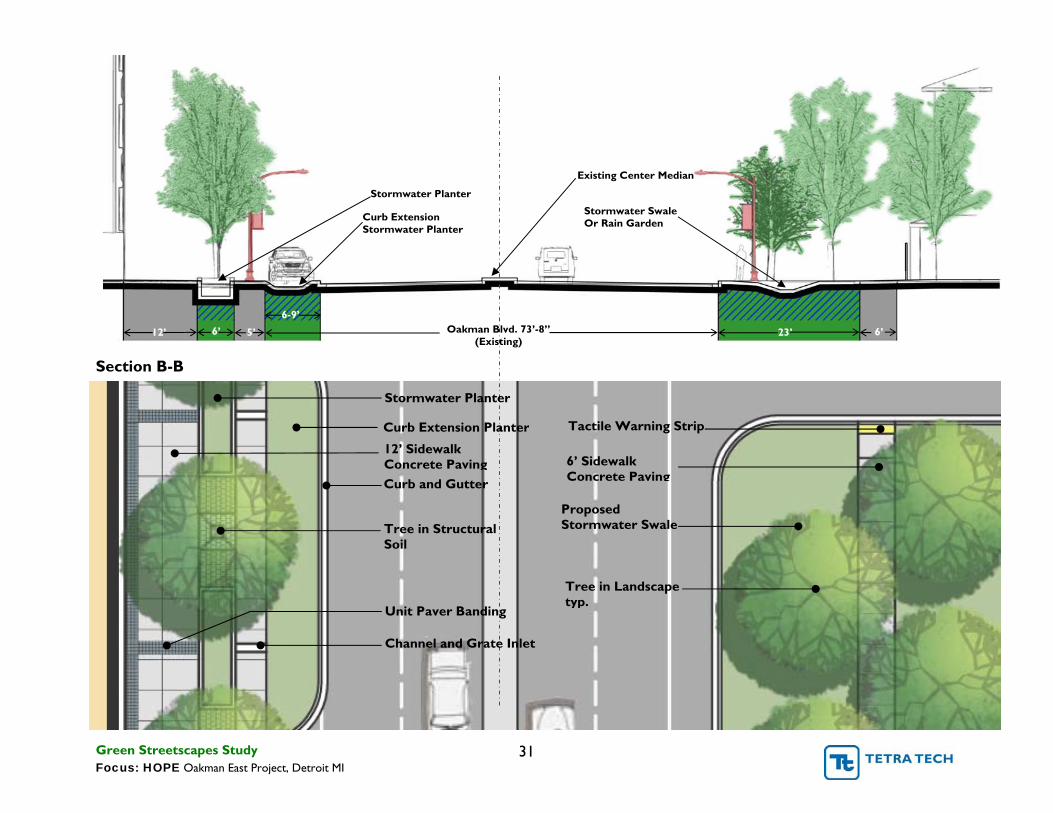
Section B-B
Stormwater Planter
Curb Extension Planter
Channel and Grate Inlet
12’ Sidewalk Concrete Paving
Unit Paver Banding
Curb and Gutter
Tree in Structural Soil
12’ Oakman Blvd. 73’-8” (Existing)
Curb Extension Stormwater Planter
6-9’ 6’ 5’ 23’ 6’
Proposed Stormwater Swale
6’ Sidewalk Concrete Paving
Tree in Landscape typ.
Stormwater Planter
Stormwater Swale Or Rain Garden
Tactile Warning Strip
Existing Center Median
Green Streetscapes Study 31 Focus: HOPE Oakman East Project, Detroit MI

Section C-C
Stormwater Planter
Channel and Grate Inlet
12’ Sidewalk Concrete Paving
Unit Paver Banding
Curb and Gutter
Tree in Structural Soil
Tree in Landscape
6’ Sidewalk Proposed Unit Paving
Swale/ Rain Garden
6’ Sidewalk Concrete Paving
Concrete or Unit Paving
Varies 6’5’
12’
6-9’ 6’ 5’
Swale/ Rain Garden
Oakman Blvd. 73’-8” (Existing)
Stormwater Planter Swale/ Rain Garden
Tactile Warning Strip
Parking Aisle Optional Porous Paving
Existing Center Median
Green Streetscapes Study 32 Focus: HOPE Oakman East Project, Detroit MI

Greening the Center Median
Sustaining vegetation in the middle of a roadway is difficult. Often plants are subjected to higher temperatures in the summer and more road salt in the winter. Where center median planting strips are narrow, plants often experience drought conditions as water typically drains away from the center of the road and is not allowed to infiltrate the planting strip soils. In order to establish successful center median plantings the median must be wide enough to provide an acceptable root zone and offer sufficient surface area so that enough rain water is allowed to infiltrate the root zone.
• It is not recommended that trees be planted in medians less than 8ft wide. Always consult an arborist or landscape architect for proper tree selection.
• Where plantings are proposed for narrow medians irrigation may be required or provisions made for periodic watering during drought conditions.
• Center median planting strips maybe designed as rain gardens where designers control grades for the complete street. Lanes may be sloped toward the median so that it receives stormwater runoff. Overflow drains located within the median will convey storm event overflow volume to the municipal storm line.
• Median planters not receiving rainwater runoff from the street and are not irrigated should be planted with hardy, drought and salt tolerant species.
Photo credit: www.co.clark.wa.us/.../klineline/photos.html
Green Streetscapes Study 33 Focus: HOPE Oakman East Project, Detroit MI

’ ’
’
’
”
5.4. Future Bike Lanes, Intersection and Median Improvements
Future reconstruction or renovation of Oakman Blvd. may offer an opportunity to improve the Oakman Blvd./ Woodrow Wilson intersection, and modify the street geometry to accommodate bike lanes, narrow travel lanes, and/or a wide vegetated center median. These modifications would contribute to meeting the 7 “Green” Streetscape Design Objectives and are important to achieving a more complete streetscape design. All three of the following concepts offer ideas for accommodating bike lanes and intersection crosswalk improvements but vary in the degree to which travel lane widths are decreased to accommodate a wider center median. Where traffic volumes permit, the design goal should be to reduce impervious surfaces and increase opportunities for alternative transportation.
Concept 1
<8 Parking <6 Bike Lane
<6 Bike Lane
<12’ Drive Lane
<8 Parking
<12’ Drive Lane
<20 Curb Median <12’ Drive Lane
<12’ Drive Lane
�
�
�
Existing curb locations remain the same. Number of traffic lanes remain the same. Space for 6’ wide dedicated bike lanes is created by
Crosswalk: � 10’ wide “Continental” style painted bars.
narrowing the existing center median to 20”.
Green Streetscapes Study 34 Focus: HOPE Oakman East Project, Detroit MI

’ ’
’
’
Concept 2 – Vegetated Median
<8 Parking Aisle <6 Bike Lane <12’ Drive Lane <9’ Center Median <12’ Left Turn Lane <12’ Drive Lane <6 Bike Lane <8 Parking Aisle
Crosswalk: �
�
Number of travel lanes are reduced from 2 in each direction to 1 in each direction with left turn only lanes where required. Eliminating the 2 travel lanes creates space for
� � �
Highly visible Streetprint®: Stamped colored asphalt Optional center median pedestrian refuge Crosswalks shown 14’ wide, 10’ wide colored walk with 2’ wide white bands on either side
dedicated bike lanes in both directions as well as a 9’ wide landscaped center median which widens to 20’
�
where left turn lanes are not required. The landscaped center median creates space for street trees which will dramatically increase the canopy cover over Oakman Blvd.
� Concept achieves 12% less impervious surface than the existing condition.
Green Streetscapes Study 35 Focus: HOPE Oakman East Project, Detroit MI

’
’
’
Concept 3 – Vegetated Median with Dedicated Bike Path
<8 Parking Aisle
<10 Bikeway
<8 Parking Aisle
<12’ Drive Lane
<12’ Drive Lane
� The number of travel lanes is reduced from 2 in each direction to 1 in each direction and left turns are only provided at block end intersections.
� Eliminating the 2 travel lanes creates space for a separated 2-way bikeway in the center median flanked by 10’ wide landscape strips on either side.
� The linear landscape strips may also be designed as bioswales for filtering and infiltrating stormwater runoff from Oakman Blvd.
� This concept requires 30% less impervious surface than the existing condition.
Crosswalk: � Durable, scored Colored Concrete � Center Median pedestrian refuge � Crosswalks shown 14’ wide, 10’ Wide Concrete walk
with 2’ Wide White bands on either side
Baltimore MD: center median bikeway
Green Streetscapes Study 36 Focus: HOPE Oakman East Project, Detroit MI

5.5. Crosswalk Design
Typical standards require that crosswalks be composed of solid white lines, 6 to 24” wide. The width of the crosswalk should be a minimum of 6”. The city of Detroit or Michigan Department of Transportation will dictate local crosswalk standards. The following layouts are most commonly used for crosswalks:
• Standard (top) • Ladder (left) • Diagonal Ladder (right) • Continental (bottom)
Standard/ Infill Crosswalk
The most common crosswalk layout, the standard, or transverse, layout consists of markings which are perpendicular to the roadway, spaced at least 6 feet apart (including the width of the lines), and are commonly 12 inches wide. The standard layout is widely used because it requires the least number of pavement markings; however, it is also the least visible to drivers. Therefore, it is best used at signalized intersections. To make the standard crosswalk more visible the space between the painted lines can be enhanced by adding a color coating and/or a stamped texture to the asphalt surface. The following page presents examples of additional paving materials which can also be used to infill the crosswalk for high visibility and enhanced aesthetics. Where cost or construction time make the infill type crosswalk impractical, a continental style painted crosswalk may be preferable. It offers high visibility, easy installation and low cost.
Paint/Coating Types • Epoxy Resin • Thermoplastics • Inlay Tape
The following page provides examples of innovative crosswalk options.
Green Streetscapes Study 37 Focus: HOPE Oakman East Project, Detroit MI

Crosswalk Materials
Scored concrete crosswalk Brick Paver crosswalk Streetprint: Color Coated and Stamped Asphalt
Colored Concrete crosswalk with brick paver edge
Infill Paving Materials Brick Imprinted Asphalt Concrete – Pattern, Colored
Streetprint: Thermoplastic patterned crosswalk in asphalt
Green Streetscapes Study 38 Focus: HOPE Oakman East Project, Detroit MI

6. Appendix
6.1. Construction Details
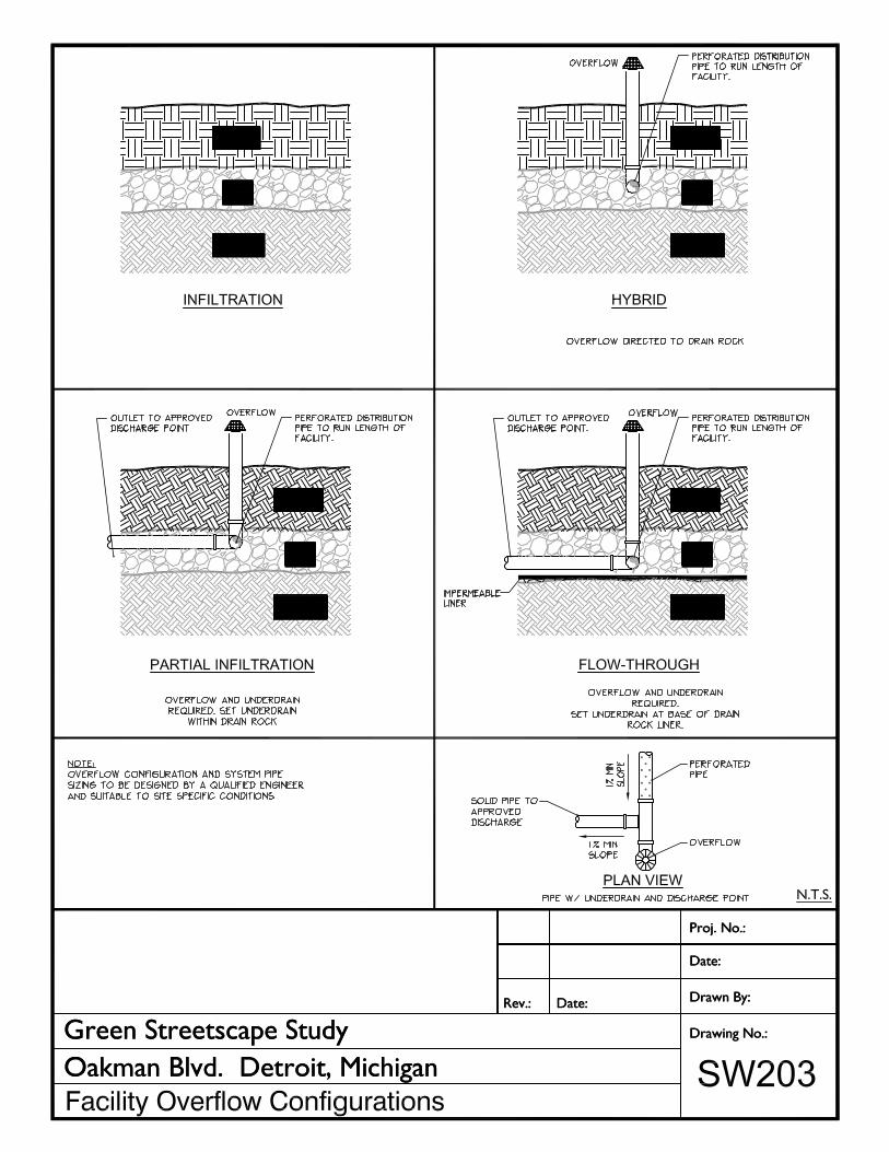
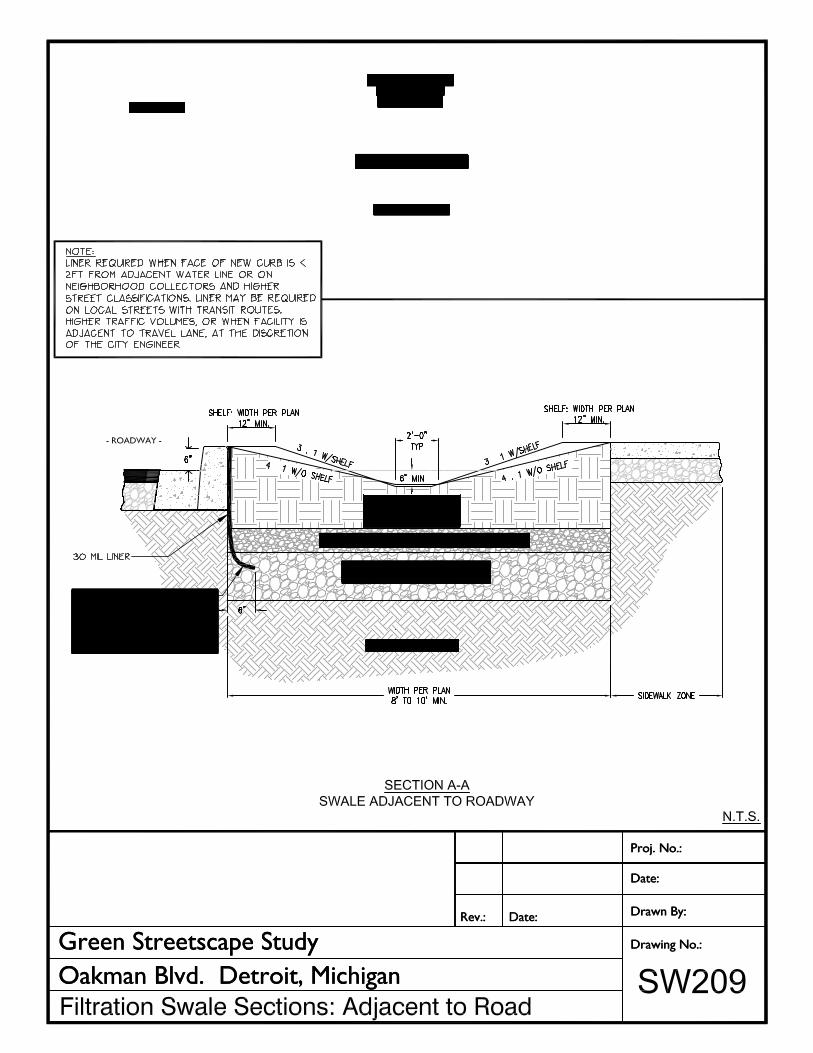
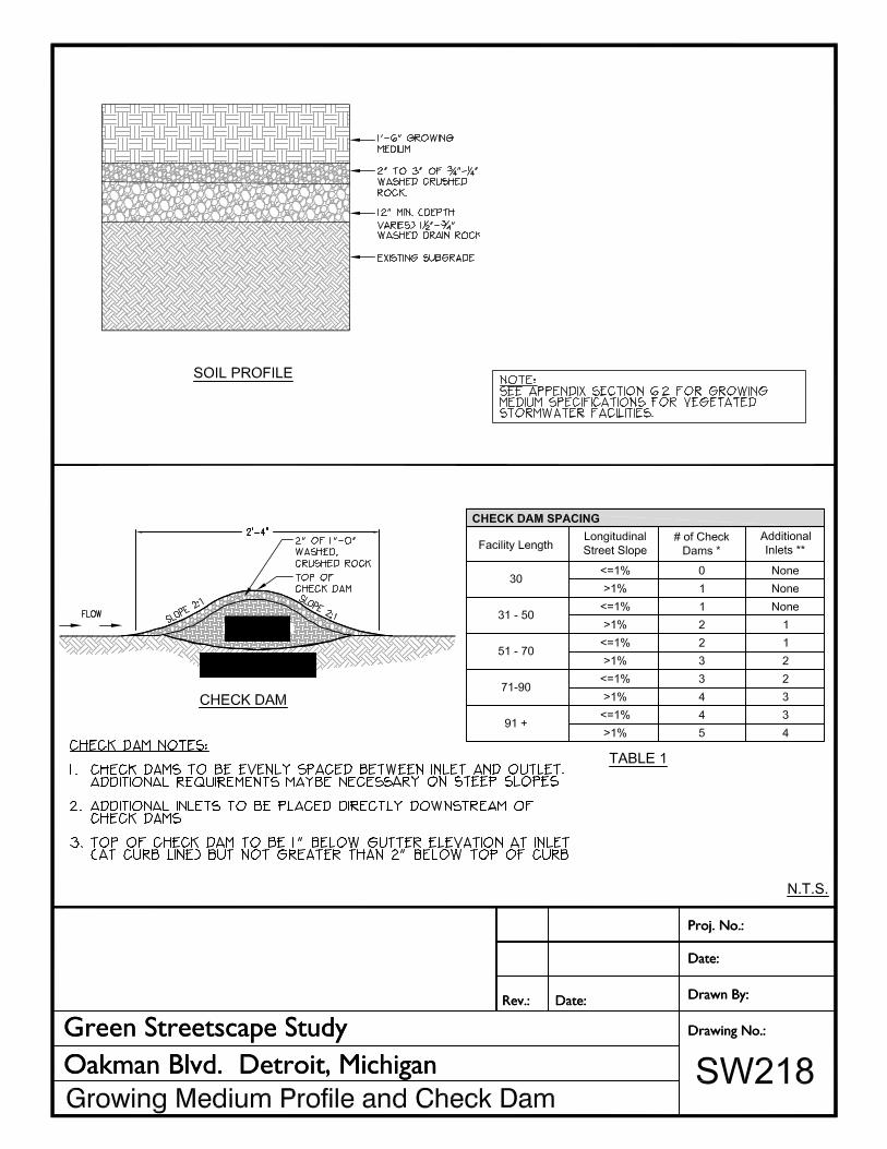
Table of Contents Pervious Paver and Asphalt Sections………………………………. PV100 Mowable Swale/ Basin…………………………………………….. SW200 Bioswale ………………………………………………………SW201 Stormwater Planter: Overflow Design……………………………. SW202 (Contaminated Soils) Facility Overflow Configurations………………………………….. SW203 Curb Extension SW Planter: Overflow Design…………………… SW204 Curb Extension SW Planter Section: Overflow Design…………... SW205 Curb Extension SW Planter: Flow Through Design……………… SW206 Curb Extension SW Planter Section: Flow Through Design……… SW207 Curb Extension SW Planter Inlet/Outlet Details………………….. SW208 Filtration Swale Section: Adjacent to Road………………………. SW209 SW Planter: Flow Through Design with Parking…………………. SW210 SW Planter Section: Flow Through Design……………………….. SW211 SW Planter Plan: Overflow Design with Parking…………………. SW212 SW Planter Section: Overflow Design with Parking………………. SW213 Concrete Inlet: For Local Service Streets…………………………. SW214 Concrete Inlet: For Collectors ……………………………………... SW215 Concrete Inlet: For Collectors ……………………………………... SW216 Concrete Inlet: Channel & Grate type………………………………SW217 Growing Medium Profile and Check Dam………………………… SW218 Street Tree Planting in Structural Soil………………………………L300
All details have been adapted for site specific use in Detroit MI. Several conceptual detail designs are by Portland Bureau of Environmental Services Stormwater Facility Handbook, City of Portland, Oregon.
Green Streetscapes Study 39 Focus: HOPE Oakman East Project, Detroit MI


6.2. Bioretention Basin Soil Specification
The following has been developed by Low Impact Development.org through a Cooperative Assistance Agreement under the US EPA Office of Water 104b(3) Program in order to provide guidance to local governments, planners, and engineers for developing, administering, and incorporating Low Impact Development (LID) into their aquatic resource protection programs.
DESCRIPTION. Bioretention facilities are small landscaped basins intended to provide water quality management by filtering stormwater runoff before release into storm drain systems. This work shall consist of installing bioretention facilities as specified in the Contract Documents, including all materials, equipment, labor and services required to perform the work.
Plant Materials See below.
Water See below.
Limestone ASTM C25
Iron Sulfate See below.
Magnesium Sulfate See below.
Potash See below. (See Comment 3)
Bioretention Soil Mixture. The Bioretention Soil Mixture (BSM) is a mixture of planting soil, mulch, and sand consisting of the following:
MATERIAL SPECIFICATION
No. 57 Aggregate ASTM 633 (See Comment 1)
No. 7 Aggregate ASTM 633 (See Comment 1)
Underdrain and Outlet Pipe, 6-inch AASHTO M278 (See Comment 1)
Mulch, 2x Shredded Hardwood Bark See below. (See Comment 2)
ITEM COMPOSITION BY VOLUME REFERENCE
Planting Soil 30% See below. (See Comment 3)
Shredded 2x Hardwood Mulch 20% See below.
(See Comment 3)
Sand (clean) 50% Michigan Department of Transportation 2NS fine aggregate
Green Streetscapes Study 40 Focus: HOPE Oakman East Project, Detroit MI
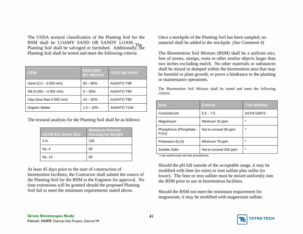
The USDA textural classification of the Planting Soil for the BSM shall be LOAMY SAND OR SANDY LOAM. The Planting Soil shall be salvaged or furnished. Additionally, the Planting Soil shall be tested and meet the following criteria:
ITEM PERCENT BY WEIGHT TEST METHOD
Sand (2.0 – 0.050 mm) 50 – 85% AASHTO T88
Silt (0.050 – 0.002 mm) 0 – 50% AASHTO T88
Clay (less than 0.002 mm) 10 – 20% AASHTO T88
Organic Matter 1.5 – 10% AASHTO T194
The textural analysis for the Planting Soil shall be as follows:
Minimum Percent ASTM E11 Sieve Size Passing by Weight 2 in. 100
No. 4 90
No. 10 80
At least 45 days prior to the start of construction of bioretention facilities, the Contractor shall submit the source of the Planting Soil for the BSM to the Engineer for approval. No time extensions will be granted should the proposed Planting Soil fail to meet the minimum requirements stated above.
Once a stockpile of the Planting Soil has been sampled, no material shall be added to the stockpile. (See Comment 4)
The Bioretention Soil Mixture (BSM) shall be a uniform mix, free of stones, stumps, roots or other similar objects larger than two inches excluding mulch. No other materials or substances shall be mixed or dumped within the bioretention area that may be harmful to plant growth, or prove a hindrance to the planting or maintenance operations.
The Bioretention Soil Mixture shall be tested and meet the following criteria:
Item Criteria Test Method
Corrected pH 5.5 – 7.5 ASTM D4972
Magnesium Minimum 32 ppm *
Phosphorus (Phosphate - P2O5)
Not to exceed 69 ppm *
Potassium (K2O) Minimum 78 ppm *
Soluble Salts Not to exceed 500 ppm *
* Use authorized soil test procedures.
Should the pH fall outside of the acceptable range, it may be modified with lime (to raise) or iron sulfate plus sulfur (to lower). The lime or iron sulfate must be mixed uniformly into the BSM prior to use in bioretention facilities.
Should the BSM not meet the minimum requirement for magnesium, it may be modified with magnesium sulfate.
Green Streetscapes Study 41 Focus: HOPE Oakman East Project, Detroit MI

Likewise, should the BSM not meet the minimum requirement for potassium, it may be modified with potash. Magnesium sulfate and potash must be mixed uniformly into the BSM prior to use in bioretention facilities.
Planting soil and/or BSM that fails to meet the minimum requirements shall be replaced at no additional cost to the Administration. Mixing of the corrective additives to the BSM is incidental and shall be at no additional cost to the Administration.
Mixing of the BSM to a homogeneous consistency shall be done to the satisfaction of the Engineer.
Placement and Compaction of the Bioretention Soil Mixture. The Bioretention Soil Mixture (BSM) shall be placed and graded using low ground-contact pressure equipment or by excavators and/or backhoes operating on the ground adjacent to the bioretention facility. (See Comment 6) No heavy equipment shall be used within the perimeter of the bioretention facility before, during, or after the placement of the BSM. The BSM shall be placed in horizontal layers not to exceed 12 inches for the entire area of the bioretention facility. The BSM shall be compacted by saturating the entire area of the bioretention facility after each lift of BSM is placed until water flows from the underdrain. Water for saturation shall be applied by spraying or sprinkling. Saturation of each lift shall be performed in the presence of the Engineer. An appropriate sediment control device shall be used to treat any sediment-laden water discharged from the underdrain. If the BSM becomes contaminated during the construction of the facility,
the contaminated material shall be removed and replaced with uncontaminated material at no additional cost to the Administration. Final grading of the BSM shall be performed after a 24-hour settling period. Final elevations shall be within 2 inches of elevations shown on the Contract Plans.
Notes:
Comment 1.
Double-washed stone preferred to reduce suspended solids and
potential for clogging. Comment 2.
This is to supply organic material, other sources can be used.
Mulch is preferred because it can be obtained on site and it is
relatively stable. Alternatively use compost
Comment 3. Avoid high clay content soils. They tend to create hard pans
and clumps that reduce filtration and storage.
Comment 4.
Allow sufficient time for testing. Suggest certified source or
laboratory to reduce mobilization time and construction delays.
Comment 5.
Use of flexible slotted HDPE is preferred. Large openings on
PVC pipe may allow sediments and larger materials to migrate
into system.
Comment 6.
Equipment will compact bottom, reducing any infiltration
capacity. The structure of the soil and pore space can be
restored by aeration/rototill.
Green Streetscapes Study 42 Focus: HOPE Oakman East Project, Detroit MI

6.3. Recommended Plant Lists
The following plant lists are a sampling of recommended vegetation suitable for the use in the City of Detroit. A Landscape Architect should be consulted for designing final planting plans as correctly locating the plants is critical to their long term survival.
Wild flowers Sages and Grasses: Vegetated Stormwater Facilities All plant material is available through Michigan Native Plant Producers Association member retailers. www.mnppa.org
Full Sun
Top (dry) *Butterfly Weed (Asclepias tuberose) – 2’ – Orange – Jun-Aug – Dry-Med *Columbine (Aquilegia canadensis) – 2’ – Red/yellow – Apr-Jun – Dry-Med Harebell (Campanula rotundifolia) – 1’ – Purple – Jun-Sep – Dry Golden Alexanders (Zizia aurea) – 3’ – Yellow – May-June – Dry-Med Rough Blazing Star (Liatris aspera) – 2’ – Purple – Jul-Sep – Dry Skyblue Aster (Aster oolentangiensis) – 2-3’ – Purple – Sep-Oct – Dry-Med Wild Geranium (Geranium maculatum) – 1’ – Apr-July – Lavender – Dry-Med
Grasses/ Sedges Pennsylvania Sedge (Carex pensylvanica) – 8” – Dry-Med Hosta (Hosta sp.) - varies Eragrostis spectabilis (Purple Love Grass) – 1’-1.5’ – Dry Plains Oval Sedge (Carex brevior) – 1’ – Dry-Moist Little Bluestem (Schizachyrum scoparium) – 2-4’ – Dry
Middle (medium ) Big-leaved Aster (Aster macrophyllus) – 1’ – White – Aug-Oct – Dry-Moist Bishop’s Cap (Mitella diphylla) – 1-2’ – White – May-Jun – Dry-Med *Black-Eyed Susan (Rudbeckia hirta) – 2’ – Yellow – Jun-Oct – Dry-Moist (use anywhere) Bottle Gentian (Gentiana andrewsii) – 3’ – Blue – Aug-Sep – Dry-Moist Calico Aster (Aster lateriflorus) – 1-3’ – White – Aug-Oct – Dry-Med Canada Anemone (Anemone canadensis) – 1’ – White – May-Jun – Med-Wet
*Golden Alexanders (Zizia aurea) – 3’ – Yellow – Apr-Jun – Dry-Med *Heath Aster (Aster ericoides) – 2’ – White – Aug-Oct – Dry-Med *Nodding Onion (Allium cernuum) – 18” – Lavender – Jul-Aug – Dry-Moist *Western Sunflower (Helianthus occidentalis) – 3’ – Yellow – July-Sep – Dry-Med
Grasses/ Sedges Hosta (Hosta sp.) - varies Little Bluestem (Schizachyrium scoparium) – 3’ – Dry-Med Prairie/Northern Dropseed (Sporobolus heterolepis) – 3’ – Dry-Moist soil
Bottom (wet) Aster laevis (Smooth Aster) – 3’ – Lavender – Aug-Oct – Med-Moist Aster novae-angliae (New England Aster) – 3-6’ – Purple – Sep-Oct – Dry-Med Early Meadow Rue (Thalictrum dioicum) – 2’ – Green – Apr-May – Dry-Moist Great Blue Lobelia (Lobelia siphilitica) – 3’ – Blue – Jul-Oct – Med-Wet Monkey Flower (Mimulus ringens) – 2’ – Violet – Jun-Sep – Moist-Wet Northern Blue Flag Iris (Iris versicolor) – 3’ – Blue – May-July – Med-Wet Black Eyed Susan (Rudbeckia hirta) – 1-3’ – Yellow – Jul-Sep – Med-Moist *Rosin Weed (Silphium integrifolium) – 3’ – Yellow – Jul-Sep – Dry-Moist Iris virginica (Blue Flag Iris) – 2-3’ – Light Blue – May-July –Wet *Spiderwort (Tradescantia ohiensis) – 3’ – Blue – May-July – Dry-Wet *Virginia Mountain Mint (Pycnanthemum virginianum) – 3’ – White – Jun-Sep – Med-Wet White Snakeroot (Eupatorium rugosum) – 2’ – White – Jul-Oct – Dry-Moist *Zig Zag Goldenrod (Solidago flexicaulis) – 3’ – Yellow – Aug-Oct – Dry-Wet
Grasses/ Sedges Juncus effusus (Soft-stemmed Rush) – 3-5’ –Moist Common Bur/Gray’s Sedge (Carex grayi) – 3’ – Moist-Wet Tussock Sedge (Carex stricta) – 2-3’ –Moist Palm Sedge (Carex muskingumensis) – 2-3’ – Med-Moist Silky Wild Rye (Elymus villosus) – 3’ – Dry-Moist Wool Grass (Scirpus cyperinus) – 2-3’ –Wet
Partial Shade
Top (dry) *Butterfly Weed (Asclepias tuberose) – 2’ – Orange – Jun-Aug – Dry-Med *Columbine (Aquilegia canadensis) – 2’ – Red/yellow – Apr-Jun – Dry-Med Smooth Pussytoes (Antennaria parlinii) – 6-12” – White – May-June – Dry Harebell (Campanula rotundifolia) – 1’ – Purple – Jun-Sep – Dry Early Goldenrod (Solidago juncea) – 2-4’ – Yellow – Sept-Oct – Dry-Med Sand Coreopsis (Coreopsis lanceolata) – 2-3’ –Yellow – June-Sep – Dry-Med Big-leaved Aster (Aster macrophyllus) – 2-3’ – Purple – Sep-Oct - Dry
Green Streetscapes Study 43 Focus: HOPE Oakman East Project, Detroit MI

Wild Geranium (Geranium maculatum) – 1’ – Apr-July – Lavender – Dry-Med
Grasses/ Sedges Common Oak Sedge/Pennsylvania Sedge (Carex pensylvanica) – 8” – Dry-Med Hosta (Hosta sp.) - varies Normal Sedge (Carex normalis) – 1-2’ – Dry-Med
Middle (medium ) Big-leaved Aster (Aster macrophyllus) – 1’ – White – Aug-Oct – Dry-Moist *Black-Eyed Susan (Rudbeckia hirta) – 2’ – Yellow – Jun-Oct – Dry-Moist (use anywhere) Calico Aster (Aster lateriflorus) – 1-3’ – White – Aug-Oct – Dry-Med Long-fruited thimbleweed (Anemone cylindrica) – 2-4’ – White – May-Jun – Dry -Med *Golden Alexanders (Zizia aurea) – 3’ – Yellow – Apr-Jun – Dry-Med *Heath Aster (Aster ericoides) – 2’ – White – Aug-Oct – Dry-Med *Nodding Onion (Allium cernuum) – 18” – Lavender – Jul-Aug – Dry-Moist *Sky Blue Aster (Aster azureus) – 3’ – Blue – Aug-Oct – Dry-Med * Foxglove Beardtongue (Penstemon digitalis) – White – 3’ – May-Jul – Dry-Med * Woodland Sunflower (Helianthus divaricatus) – 3’ – Yellow – July-Sep – Dry- Nodding Wild Onion (Allium cernuum) – 18” – Pink – May-July – Dry-Moist
Grasses/ Sedges Hosta (Hosta sp.) - varies Little Bluestem (Schizachyrium scoparium) – 3’ – Dry-Med Prairie Sedge (Carex bicknelii) – 2-3’ – Moist-Dry soil
Bottom (wet) Calico Aster (Aster lateriflorus) – 2-4’ – White – Aug-Oct – Med-Moist Early Meadow Rue (Thalictrum dioicum) – 2’ – Green – Apr-May – Dry-Moist Great Blue Lobelia (Lobelia siphilitica) – 3’ – Blue – Jul-Oct – Med-Wet Monkey Flower (Mimulus ringens) – 2’ – Violet – Jun-Sep – Moist-Wet Northern Blue Flag Iris (Iris versicolor) – 3’ – Blue – May-July – Med-Wet *Spiderwort (Tradescantia ohiensis) – 3’ – Blue – May-July – Dry-Wet *Virginia Mountain Mint (Pycnanthemum virginianum) – 3’ – White – Jun-Sep – Med-Wet White Snakeroot (Eupatorium rugosum) – 2’ – White – Jul-Oct – Dry-Moist *Zig Zag Goldenrod (Solidago flexicaulis) – 3’ – Yellow – Aug-Oct – Dry-Wet
Grasses/ Sedges Common Bur/Gray’s Sedge (Carex grayi) – 3’ – Moist-Wet Slender Sedge (Carex gracillima) – 2-3’ –Med-Wet Palm Sedge (Carex muskingumensis) – 2-3’ – Med-Moist Silky Wild Rye (Elymus villosus) – 3’ – Dry-Moist
Full Shade
Top (dry) Big-leaved Aster (Aster macrophyllus) – 1’ – White – Aug-Oct – Dry-Moist Columbine (Aquilegia canadensis) – 2’ – Red/yellow – Apr-Jun – Dry-Med Rue Anemone (Amemonella thalictroides) – 6” – Pink – Apr-Jun – Dry-Med Grasses/SedgesCommon Oak Sedge/Pennsylvania Sedge (Carex pensylvanica) – 8” – Dry-Med Hosta (Hosta sp.) - varies Hairy Wood Sedge (Carex hirtifolia) – 12” – Dry-Med
Middle (medium ) Calico Aster (Aster lateriflorus) – 1-3’ – White – Aug-Oct – Dry-Med Golden Alexanders (Zizia aurea) – 3’ – Yellow – Apr-Jun – Dry-Med Thimbleweed (Anemone virginiana) – 2-4’ – White– Jun-Aug– Moist-Dry Heuchera americana (Alumroot) – 1’-4’ – Green – June-Aug – Dry-Med Early Meadowrue (Thalictrum dioicum) – 18-30” – Green – May-July – Dry-Moist Grasses/SedgesHairy Wood Sedge (Carex hirtifolia) – 12” – Dry-Med Hosta (Hosta sp.) - varies Long-Beaked Sedge (Carex sprengelii) – 2’ – Dry-Moist
Bottom (wet) Calico Aster (Aster lateriflorus) – 2-4’ –White – Sep-Oct – Wet-Moist Early Meadow Rue (Thalictrum dioicum) – 2’ – Green – Apr-May – Dry-Moist Cow Parsnip (Heracleum maximum) – 3-7’ – White – June-Aug – Wet-Moist White Snakeroot (Eupatorium rugosum) – 2’ – White – Jul-Oct – Dry-Moist Zig Zag Goldenrod (Solidago flexicaulis) – 3’ – Yellow – Aug-Oct – Dry-Wet Grasses/SedgesLong-awned Wood Grass (Brachyeletrum erectum) – 6-24” – Wet-Moist Common Bur/Gray’s Sedge (Carex grayi) – 3’ – Moist-Wet Slender Sedge (Carex gracillima) – 2-3’ – Moist-Wet Lady Fern (Athyrium filix-femina) – 18” – Med-Moist Maidenhair Fern (Adiantum pedatum) – 2’ – Med-Moist Silky Wild Rye (Elymus villosus) – 3’ – Dry-Moist
Green Streetscapes Study 44 Focus: HOPE Oakman East Project, Detroit MI

Medium-Large Street Trees
Common Name Latin Name Height Spread Notes
“Autmn Blaze’ Freeman maple Acer x freemanii 50-55ft 30-40ft Sugar Maple Acer Saccharum 60-80ft 40-50ft Red maple Acer rubrum 40-60ft Salt sensitive, ‘Red Sunset’ has
good flood tolerance Upright European hornbeam Carpinus betulus ‘Fastigiata’ 35ft 25ft Salt Sensitive Katsura tree Cercidiphyllum japonicum 40ft
40ft
Not for compacted soils Turkish filbert Corylus colurna 40-50ft 20-30ft Gingko Gingko biloba
40-50ft
Some salt tolerance Kentucky coffee tree Gymnocladus dioicus 60-75ft 40-50ft Thornless honeylocust inermis Gleditsia triacanthos 40-100ft 40ft Sweetgum Liquidambar styraciflua 70-100ft 40-65ft Tolerates intermittent flooding Tulip tree Liriodendron tulipifera 80-120ft 35-50ft Salt sensitive Dawn redwood Metasequoia glyptostroboides 70-100ft 25ft Salt sensitive, Requires moist
site London planetree Platanus x acerifolia 50ft
40ft
Salt tolerant, tolerate intermittent flooding
Amur corktree Phellodendron amurense 30-45ft 40-50ft Callery pear Pyrus calleryana
50ft 30ft
Tolerant of Moist& Dry Sites Swamp white oak Quercus bicolor
45ft
45ft
Tolerates temporary flooding, wet soils and somewhat dry soils. Salt sensitive.
Sawtooth oak Quercus acutissima
40ft 40ft
Tolerates moderately dry soils. Moderate salt tolerance.
Northern pin oak Quercus ellipsoidalis
50-60ft
50ft
Moisture adaptable Bur oak Quercus macrocarpa
55ft 45ft
Tolerates drought & intermittent flooding
Japanese pagodatree Sophora japonica 50-70ft 40-70ft Salt tolerant Linden or Basswood Tilia americana
35-50ft
25-30ft
Salt sensitive Silver linden Tilia tomentosa 50-70ft 30-50ft Little-leaf linden Tilia cordata
60-70ft
40-50ft
Pollution tolerant Elm hybrids Ulmus spp. 40-50ft 30-50ft Tolerates intermittent flooding
and drought Japanese zelkova Zelkova serrata 50-80ft 40-50ft
Green Streetscapes Study 45 Focus: HOPE Oakman East Project, Detroit MI
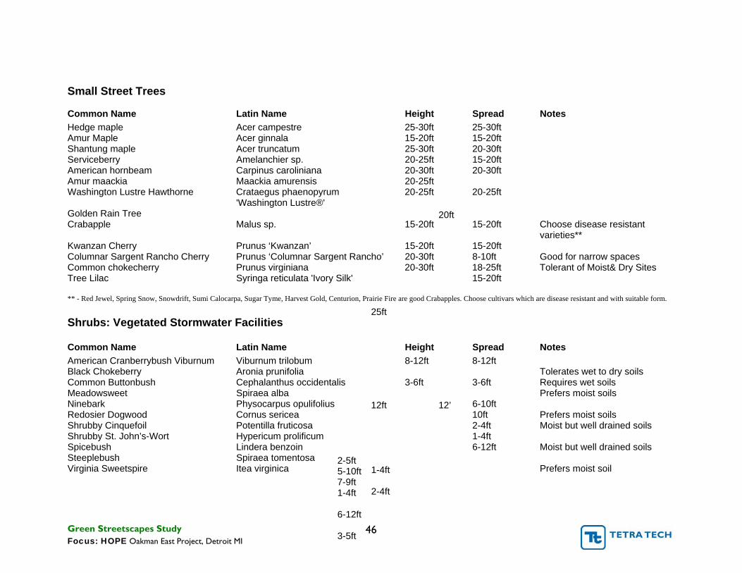
Small Street Trees
Common Name Latin Name Height Spread Notes Hedge maple Acer campestre 25-30ft 25-30ft Amur Maple Acer ginnala 15-20ft 15-20ft Shantung maple Acer truncatum 25-30ft 20-30ft Serviceberry Amelanchier sp. 20-25ft 15-20ft American hornbeam Carpinus caroliniana 20-30ft 20-30ft Amur maackia Maackia amurensis 20-25ft
20ft
Washington Lustre Hawthorne Crataegus phaenopyrum 20-25ft 20-25ft 'Washington Lustre®'
Golden Rain Tree Crabapple Malus sp. 15-20ft 15-20ft Choose disease resistant
varieties** Kwanzan Cherry Prunus ‘Kwanzan’ 15-20ft 15-20ft Columnar Sargent Rancho Cherry Prunus ‘Columnar Sargent Rancho’ 20-30ft 8-10ft Good for narrow spaces Common chokecherry Prunus virginiana 20-30ft 18-25ft Tolerant of Moist& Dry Sites Tree Lilac Syringa reticulata 'Ivory Silk'
25ft
15-20ft
** - Red Jewel, Spring Snow, Snowdrift, Sumi Calocarpa, Sugar Tyme, Harvest Gold, Centurion, Prairie Fire are good Crabapples. Choose cultivars which are disease resistant and with suitable form.
Shrubs: Vegetated Stormwater Facilities
Common Name Latin Name Height Spread Notes American Cranberrybush Viburnum Viburnum trilobum 8-12ft 8-12ft Black Chokeberry Aronia prunifolia
12ft 12’
Tolerates wet to dry soils Common Buttonbush Cephalanthus occidentalis 3-6ft 3-6ft Requires wet soils Meadowsweet Spiraea alba
2-5ft
Prefers moist soils Ninebark Physocarpus opulifolius
5-10ft
6-10ft Redosier Dogwood Cornus sericea
7-9ft
10ft Prefers moist soils Shrubby Cinquefoil Potentilla fruticosa
1-4ft
2-4ft Moist but well drained soils Shrubby St. John’s-Wort Hypericum prolificum
1-4ft
1-4ft Spicebush Lindera benzoin
6-12ft
6-12ft Moist but well drained soils Steeplebush Spiraea tomentosa
2-4ft
Virginia Sweetspire Itea virginica
3-5ft
Prefers moist soil
Green Streetscapes Study 46 Focus: HOPE Oakman East Project, Detroit MI

6.4. SMF Maintenance Guidelines
(SMF)Stormwater Management Facilities require more maintenance than traditional below ground stormwater infrastructure. Although none of the maintenance activates are technically difficult they are critical to the effectiveness and longevity of the SMFs. The following chart suggests several maintenance activities as well as the frequency for performing them.
Bioinfiltration/Bioretention Maintenance Guidelines
Activity Schedule
Water vegetation at the end of each day for two weeks after planting is completed. Water vegetation regularly to ensure successful establishment.
First year after installation or as needed during drought conditions
Inspect soil and repair eroded areas. Remove litter and debris. Clear leaves and debris from overflow. Monthly
Inspect facility several times the first few months to ensure vegetated cover is establishing well. If not, reassess or plant an alternative species. Once established, continue to inspect semi-annually for erosion problems.
Twice Per Year
Inspect underdrain cleanout. Verify drained out time of system. Twice Per Year
Inspect trees and shrubs to evaluate health, replace if necessary. Twice Per Year
If rock is used as a drainage component, inspect for clogging from excess sediment. Annually
Mow turf grass to a height of four to six inches. If native grasses are used, mow only once a year in early spring to remove dead vegetation. Mowing the native grasses the first year is critical in order to eliminate competition from annual weeds.
Turf grass -As needed Native Grasses -Annually
Remove weeds/ invasive species to ensure they don’t crowd out the planted material
As needed. Minimum twice during growing season
Remulch void areas. Treat diseased trees and shrubs. As needed
Remove sediment buildup on the bottom of facility once it has accumulated to 25 percent of original design volume. As needed
Maintain records of all inspections and maintenance activity. Ongoing
Green Streetscapes Study 47 Focus: HOPE Oakman East Project, Detroit MI

6.5. Streetscape SMF Sizing Guide
The following content is adapted from The New York State Stormwater Management Design Manual, April 2008. They guides offer simplified formulas for calculating the size of SMFs, Stormwater Planters and Rain Gardens, required to treat runoff from a given area.
Stormwater Planters and Rain Gardens are particularly cost effective when treating relatively small areas. The sizing of such measures is dependant on the pollutant removal goals. A generally accepted practice is to capture and treat 90% of the average annual stormwater volume. This is denoted as the Water Quality Volume. Sizing and Design guidance and example calculations on how to do this is provided in the following pages. These examples assume a basic knowledge of runoff hydrology, statistical rainfall data, and soil mechanics. While useful in determining the extent of mitigation measures required, it is strongly suggested that you consult with an engineer or landscape architect prior to implementing such practices.
Stormwater Planters
Sizing and Design Guidance
Stormwater planters should initially be sized to satisfy the WQv requirements for the impervious surface area draining to the practice. This does not apply to contained planters because
they are designed to decrease impervious area, not receive additional runoff from adjacent surfaces. The basis for the sizing guidance is the same as that for bioretention and relies on the principles of Darcy’s Law, where water is passed through porous media with a given head, a given hydraulic conductivity, over a given timeframe (Flinker, 2005). The equation for sizing an infiltration or flow-through stormwater planter based upon the contributing area is as follows:
Af = WQv x (df)/ [k x (hf + df)(tf)]
where:
Af = the required surface area [square feet]
Vol = the treatment volume [cubic feet]
df = depth of the soil medium [feet]
k = the hydraulic conductivity [in ft/day, usually set
4 ft/day, but can be varied depending on the
properties of the soil media] hf = average height of water above the planter bed [maximum 12 inches] tf = the design time to filter the treatment volume through
the filter media [usually set at 3 or 4 hours] WQv = water quality volume [cubic feet]
Green Streetscapes Study 48 Focus: HOPE Oakman East Project, Detroit MI

A simple example for sizing a stormwater planter using WQv There are numerous sizing, siting, and material specification
is presented the Table below. The ultimate size of a stormwater guidelines that should be additionally consulted during planter is a function of either the impervious area or the stormwater planter design.
infiltration capacity of the media.
Determine the required surface area of a stormwater planter that will be installed to treat stormwater runoff from an impervious area of 3,000 square feet, given the depth of the soil medium is 1.5 feet. Step 1: Calculate the WQv
WQv = (P) (Rv) (A) 12
where: P = 90% rainfall number = 0.9 in Rv = 0.05+0.009 (I) = 0.05+0.009(100) = 0.95 I = percentage impervious area draining to site = 100% A = Area draining to practice = 3,000 ft2
WQv = (0.9)(0.95)(3,000) 12 WQv = 213.75 ft3
Step 2: Calculate required surface area: Af = WQv*(df) / [k*(hf +df)(tf)]
where: WQv = 213.75 ft3
df = depth of soil medium = 1.5 ft k = hydraulic conductivity = 4 ft/day hf = height of water above planter bed = 0.5 ft tf = filter time = 0.17 days
(213.75)(1.5) Af = [(4)(0.5+1.5)(0.17)] Af = 235.75
Green Streetscapes Study 49 Focus: HOPE Oakman East Project, Detroit MI

Rain Gardens
Sizing and Design Guidance
Stormwater quantity reduction in rain gardens occurs via evaporation, transpiration, and infiltration, though only the infiltration capacity of the soil and drainage system is considered for water quality sizing. The storage volume of a rain garden is achieved within the gravel bed, soil medium and ponding area above the bed. The size should be determined using the water quality volume (WQv), where the site area is the impervious area draining to the rain garden. The following sizing criteria should be followed to arrive at the surface area of the rain garden, based on the required WQv: WQv ≤ VSM + VDL + (DP x ARG) VSM = ARG x DSM x Nsm
VDL (optional) = ARG x DDL x nDL
where:
VSM = volume of the soil media [cubic feet]
VDL = volume of the drainage layer [cubic feet]
ARG = rain garden surface area [square feet]
DSM = depth of the soil media, typically 1.0 to 1.5 feet [feet]
DDL = depth of the drainage layer, typically .05 to 1.0 feet
[feet]
DP = depth of ponding above surface, maximum 0.5 feet [feet]
nSM = porosity of the soil media (≥20%)
nDL = porosity of the drainage layer (≥40%) WQv = Water Quality Volume [cubic feet] A simple example for sizing rain gardens based upon WQv is
presented in the Table below.
Given a 1,000 square foot impervious drainage area (e.g., rooftop), a rain garden design has been proposed with a 200 square foot surface area, a soil layer depth of 12 inches, a drainage layer depth of 6 inches, and an allowable ponding depth of 3 inches. To evaluate if the proposed rain garden design satisfies site WQv requirements
Step 1: Calculate water quality volume using the following equation:
WQv = (P) (Rv) (A) 12
where:
P = 90% rainfall number = 0.9 in Rv = 0.05+0.009 (I) = 0.05+0.009(100) = 0.95 I = Percentage impervious area draining to site = 100% A = Area draining to practice (treatment area) = 1,000 ft2
WQv = (0.9)(0.95)(1,000) 12 WQv = 71.25 ft3
Step 2: Solve for drainage layer and soil media storage volume:
VSM= ARGx DSMx PSM
VDL= ARGx DDL x PDL
where: ARG= proposed rain garden surface area = 200 ft2
DSM= depth soil media = 12 inches = 1.0 ft DDL= depth drainage layer = 6 inches = 0.5 ft PSM= porosity of soil media = 0.20 PDL= porosity of drainage layer = 0.40 VSM= 200 ft2 x 1.0 ft x 0.20 = 40 ft3
VDL= 200 ft2 x 0.5 ft x 0.40 = 40 ft3
DP = ponding depth = 3 inches = 0.25 ft WQv ≤VSM+VDL+(DPx ARG) = 40 ft3 + 40 ft3 + (0.25 ft x 200 ft2)
WQv = 71.25 ft3 ≤130.0 ft3 , OK
Therefore, the proposed design for treating an area of 1,000 ft2satisfies the WQv requirements .
Green Streetscapes Study 50 Focus: HOPE Oakman East Project, Detroit MI
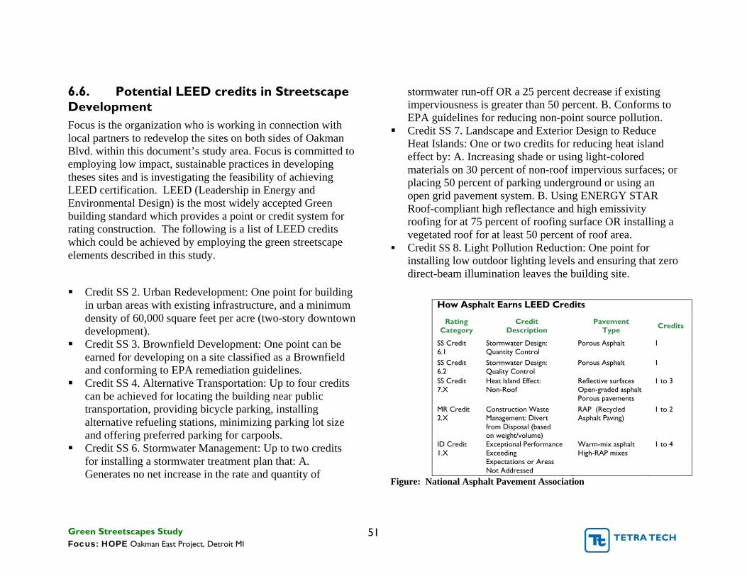
6.6. Potential LEED credits in Streetscape Development Focus is the organization who is working in connection with local partners to redevelop the sites on both sides of Oakman Blvd. within this document’s study area. Focus is committed to employing low impact, sustainable practices in developing theses sites and is investigating the feasibility of achieving LEED certification. LEED (Leadership in Energy and Environmental Design) is the most widely accepted Green building standard which provides a point or credit system for rating construction. The following is a list of LEED credits which could be achieved by employing the green streetscape elements described in this study.
� Credit SS 2. Urban Redevelopment: One point for building in urban areas with existing infrastructure, and a minimum density of 60,000 square feet per acre (two-story downtown development).
� Credit SS 3. Brownfield Development: One point can be earned for developing on a site classified as a Brownfield and conforming to EPA remediation guidelines.
� Credit SS 4. Alternative Transportation: Up to four credits can be achieved for locating the building near public transportation, providing bicycle parking, installing alternative refueling stations, minimizing parking lot size and offering preferred parking for carpools.
� Credit SS 6. Stormwater Management: Up to two credits for installing a stormwater treatment plan that: A. Generates no net increase in the rate and quantity of
stormwater run-off OR a 25 percent decrease if existing imperviousness is greater than 50 percent. B. Conforms to EPA guidelines for reducing non-point source pollution.
� Credit SS 7. Landscape and Exterior Design to Reduce Heat Islands: One or two credits for reducing heat island effect by: A. Increasing shade or using light-colored materials on 30 percent of non-roof impervious surfaces; or placing 50 percent of parking underground or using an open grid pavement system. B. Using ENERGY STAR Roof-compliant high reflectance and high emissivity roofing for at 75 percent of roofing surface OR installing a vegetated roof for at least 50 percent of roof area.
� Credit SS 8. Light Pollution Reduction: One point for installing low outdoor lighting levels and ensuring that zero direct-beam illumination leaves the building site.
How Asphalt Earns LEED Credits
Rating Credit Pavement Credits Category Description Type
SS Credit Stormwater Design: Porous Asphalt 1 6.1 Quantity Control SS Credit Stormwater Design: Porous Asphalt 1 6.2 Quality Control SS Credit Heat Island Effect: Reflective surfaces 1 to 3 7.X Non-Roof Open-graded asphalt
Porous pavements MR Credit Construction Waste RAP (Recycled 1 to 2 2.X Management: Divert Asphalt Paving)
from Disposal (based on weight/volume)
ID Credit Exceptional Performance Warm-mix asphalt 1 to 4 1.X Exceeding High-RAP mixes
Expectations or Areas Not Addressed
Figure: National Asphalt Pavement Association
Green Streetscapes Study 51 Focus: HOPE Oakman East Project, Detroit MI

References
Bassuk, Nina. CU-Structural Soil: An Update after More than a Decade of Use in the Urban Environment. City Trees: The Journal of the Society of Municipal Arborists. Jan./Feb. 2008.
Burden, Dan. Glatting Jackson and Walkable Communities Inc. Urban Street Trees, 22 Benefits, August 2006
Emeryville, California. Stormwater Guidelines for Green, Dense Redevelopment. Retrieved February 5, 2009, from www.ci.emeryville.ca.us/planning/stormwater.html
LEED. U.S. Green Building Council Web Site. www.usgbc.org
Low Impact Development Center, Inc. (LID). Retrieved April 24, 2009. http://www.lidstormwater.net/lid_techniques.htm
Michigan DEQ. LID Manual for Michigan. SEMCOG, Detroit MI., 2008. Retrieved April 20, 2009, from http://www.michigan.gov/deq/0,1607,7-1353308_3323-207334--,00.html
New York DEC. New York State Stormwater Management Design Manual. Retrieved February 10, 2009, from http://www.dec.ny.gov/chemical/29072.html
Pennsylvania DEP. Pennsylvania Stormwater Best Management Practices Manual. Retrieved February 10, 2009, from http://www.depweb.state.pa.us
Portland, City of. 2008 Stormwater Management Manual Retrieved February 10, 2009, from http://www.portlandonline.com/bes/index.cfm?c=47952 &
U.S. EPA. 2005. Reducing Urban Heat Islands: Compendium of Strategies, Cool Pavements. Retrieved February 10, 2009, from www.epa.gov/heatisland/resources/pdf/CoolPavesCom pendium.pdf
U.S. EPA. 2007. Reducing Stormwater Costs through Low Impact Development (LID) Strategies and Practices. EPA 841-F-07-006. Retrieved April 2, 2008, from www.epa.gov/owow/nps/lid/costs07/documents/reducin gstormwatercosts.pdf
U.S. EPA. Case Studies for Stormwater Management on Compacted, Contaminated Soils in Dense Urban Areas Solid Waste and Emergency Response (5105T) EPA-560-F-07-232 Retrieved February 10, 2009, from www.epa.gov/brownfields
U.S. EPA’s Green Infrastructure Web site www.epa.gov/npdes/greeninfrastructure
Green Streetscapes Study 52 Focus: HOPE Oakman East Project, Detroit MI