Street Layout, Design and Traffic Management …...Liveable Neighbourhoods Street Layout, Design and...
59
Liveable Neighbourhoods Street Layout, Design and Traffic Management Guidelines for testing and review JUNE 2000 T H E G O V E R N M E N T O F W E S T E R N A U S T R A L I A
Transcript of Street Layout, Design and Traffic Management …...Liveable Neighbourhoods Street Layout, Design and...
Liveable Neighbourhoods Street Layout, Design and Traffic Management Guidelines
f o r t e s t i n g a n d r e v i e w
J U N E 2 0 0 0
TH
E
GOVERNMENTO
F
WE
STERN AUSTRAL
IA
Liveable NeighbourhoodsStreet Layout, Design and Traffic Management Guidelines
These traffic management guidelines have been prepared to accompany the Liveable Neighbourhoods Community Design Code
Based on a report by
ERM Mitchell McCotter Pty Ltdwith TTM Consulting Pty Ltd, Roberts Day Group Pty Ltd and Curtin Consulting Services Ltd
Published by
Western Australian Planning CommissionAlbert Facey House
469 Wellington StreetPerth 6000 Western Australian
J U N E 2 0 0 0

© State of Western Australia
Published by theWestern Australian Planning Commission
Albert Facey House469 Wellington Street
Perth, Western Australia 6000
Published June 2000
ISBN 0 7309 9155 5
Internet: http://www.planning.wa.gov.auE-mail: [email protected]
Fax: (08) 9264 7566Phone: (08) 9264 7777TTY: (08) 9264 7535Infoline: 1800 626 477
Copies of this document are available in alternative formats on application to theDisability Services Coordinator
Page iii
TABLE OF CONTENTS
Page No. ____________________________________________________________________________________________________________________ 1.0 INTRODUCTION 1.1 Purpose of These Traffic Management Guidelines 1 1.2 Liveable Neighbourhoods Overview 1 1.3 Town and Neighbourhood Structuring 5 1.4 Link between Urban Design and These Traffic Management Guidelines 5 1.5 Diagrams in These Guidelines 6 1.6 Street Type Terminology 6 2.0 STREET LAYOUT GUIDELINES 2.1 Introduction 8 2.2 Access onto Arterials 8 2.3 Neighbourhood Connectors and Access Streets 11 2.4 Managing Intersection Configurations along Neighbourhood Connectors 11 2.5 Layout of Access Streets 16 2.5.1 Two Types of Access Streets 16 2.5.2 Street Length and Safe Priority Controlled Intersections of Access Streets 16 2.5.3 Guidelines for Achieving a Legible Access Street Layout 20 3.0 STREET CROSS SECTION DESIGN 3.1 Factors Influencing Street Function and Cross Section 21 3.2 Network Connectivity and Street Length of Access Streets 24 3.3 Bus Route 24 3.4 Shared Paths 24 3.5 Land Use Density/Frontage Type 25 3.6 Rear Laneways and Associated Street Cross Section Design 29 3.7 Traffic Volumes and Operating Speed 29

Page iv
TABLE OF CONTENTS (cont) Page No. ____________________________________________________________________________________________________________________ 4.0 INTERSECTION CONTROL GUIDELINES 4.1 Introduction 31 4.2 Traffic Control and Intersection Type 31 4.3 Signals on Arterials 31 4.4 ‘Primary’ and ‘Intermediate’ Roundabouts on Neighbourhood Connectors 34 4.5 Stop/Give Way at Access Street Intersections 34 4.6 Guidelines for Priority Controlled 4-way Intersections 35 4.7 Corner Truncations and Kerb Return Radii at Intersections 36 4.7.1 Corner Truncations 36 4.7.2 Kerb Return Radii 37 5.0 INTEGRATED SYSTEM PERFORMANCE REVIEW 5.1 Street Layout Performance 38 5.2 Street Cross Section Suitability 38 5.3 Intersection Configuration and Control 38 5.4 Examples of Traffic Management Plans 39 APPENDICES A MOVEMENT NETWORK DESIGN PROCESS 42 B TECHNICAL INVESTIGATIONS 47 C GLOSSARY OF TERMS 52
Page v
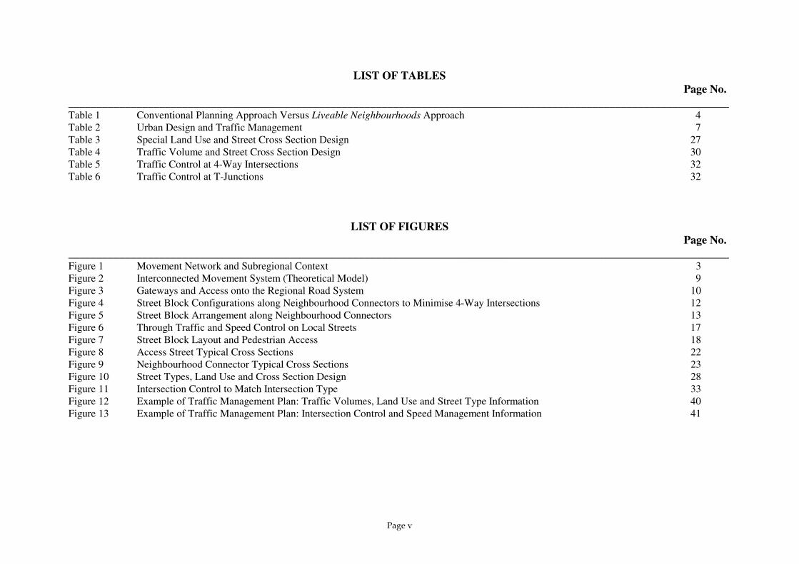
LIST OF TABLES Page No. ____________________________________________________________________________________________________________________ Table 1 Conventional Planning Approach Versus Liveable Neighbourhoods Approach 4 Table 2 Urban Design and Traffic Management 7 Table 3 Special Land Use and Street Cross Section Design 27 Table 4 Traffic Volume and Street Cross Section Design 30 Table 5 Traffic Control at 4-Way Intersections 32 Table 6 Traffic Control at T-Junctions 32
LIST OF FIGURES Page No. ____________________________________________________________________________________________________________________ Figure 1 Movement Network and Subregional Context 3 Figure 2 Interconnected Movement System (Theoretical Model) 9 Figure 3 Gateways and Access onto the Regional Road System 10 Figure 4 Street Block Configurations along Neighbourhood Connectors to Minimise 4-Way Intersections 12 Figure 5 Street Block Arrangement along Neighbourhood Connectors 13 Figure 6 Through Traffic and Speed Control on Local Streets 17 Figure 7 Street Block Layout and Pedestrian Access 18 Figure 8 Access Street Typical Cross Sections 22 Figure 9 Neighbourhood Connector Typical Cross Sections 23 Figure 10 Street Types, Land Use and Cross Section Design 28 Figure 11 Intersection Control to Match Intersection Type 33 Figure 12 Example of Traffic Management Plan: Traffic Volumes, Land Use and Street Type Information 40 Figure 13 Example of Traffic Management Plan: Intersection Control and Speed Management Information 41
Introduction
Page 1
1.0 INTRODUCTION This chapter reviews the objectives of the Liveable Neighbourhoods Community Design Code (Liveable Neighbourhoods) and examines the relationship between urban design and the guidelines for street layout, design and traffic management which are the principal subject of this publication. For simplicity these guidelines will be referred to as ‘Traffic Management Guidelines’ throughout the remainder of the document. 1.1 Purpose of these Traffic Management Guidelines Liveable Neighbourhoods was introduced by the Western Australian Planning Commission (WAPC) for a trial period for testing and review. The trial has been extended until February 2001. Liveable Neighbourhoods is an assessment tool for structure plans and subdivisions for green field urban development. During the initial one year trial period a need was identified to provide further guidance on Design Element 2: Movement Network to assist planners and engineers during the subdivision and road design and assessment phases. These Traffic Management Guidelines build on the current body of knowledge of planning and traffic engineering to provide solutions that meet the aims of Liveable Neighbourhoods. They can be used by planners and traffic engineers in assessing proposed designs submitted under Liveable Neighbourhoods. They are also intended to help give design guidance for consultants preparing proposals. Readers will find it useful to have a copy of Liveable Neighbourhoods at hand as this document makes frequent reference to it. Should any issues arise with other authorities the Ministry for Planning should be contacted to discuss the reasons behind the approach in the guidelines.
Liveable Neighbourhoods is an evolving policy that is subject to testing and review during a trial period. These Traffic Management Guidelines will similarly evolve with practice and through discussion. They are available for trial and open for comment for this purpose. Any comments should be sent to:
Mr Robin White Senior Transport Engineer Transport Planning Branch Ministry for Planning 469 Wellington Street Perth WA 6000 Phone: (08) 9264-7724 Fax: (08) 9264-7566 email: [email protected]
These guidelines will be reviewed concurrently with Liveable Neighbourhoods following its trial period.
1.2 Liveable Neighbourhoods Overview Liveable Neighbourhoods promotes a more traditional spatial structure for new developments and provides an alternative approach to the design of neighbourhoods and towns to achieve compact, well-defined and more sustainable communities. It provides an approach to movement networks, street design and intersection control to support communities of neighbourhoods. Communities are based on a system of ‘walkable neighbourhoods’. The neighbourhoods comprise land within a five-minute walk, or 400-metre radius. They are shown as circles with an area of around 50 hectares.

Introduction
Page 2
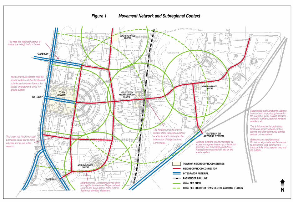
Where a site is of sufficient size, neighbourhoods are clustered together around a central town. Neighbourhood centres are no longer located in the centre of ‘cells’. Arterial streets and important local streets called Neighbourhood Connectors form the spine of the neighbourhoods and town, rather than the edges. Neighbourhood and town centres are located at the junction of these streets, reflecting their economic value in the modern movement economy. In this way the passing vehicle traffic supplements the local neighbourhood pedestrian and cyclist traffic in supporting the local shops (refer to Figure 1). Liveable Neighbourhoods provides for a highly interconnected network of streets. The interconnected network allows compatible land uses that are required for daily needs to be located with walkable access and proximity. This provides a viable alternative to the need to drive from one land use to another, thus reducing traffic congestion on Arterial streets. Culs-de-sac become less frequent, and are normally located near the far edge of a neighbourhood or town. They should be placed in a through reservation for pedestrian and cycle access and located so that they do not impede overall connectivity. All streets, including Arterial streets and Neighbourhood Connectors, have an important role in the urban structure. They contribute to community liveability by integrating all modes of travel including motoring, walking, cycling and using public transport; and by supporting active land uses on both sides. The emphasis is upon connectivity, amenity and integration to achieve safe, efficient and attractive street networks. The interconnected street system provides for ‘perimeter block’ development. Development fronts streets and open spaces, which is important for passive surveillance of these public spaces to provide for personal safety. On busier streets, service roads, laneways or lot layout
techniques are used to enable development to front arterial routes, rather than back fencing. Personal safety of pedestrians is also achieved through avoiding segregated trails and narrow pedestrian underpasses in favour of on-street footpaths and safe pedestrian crossings at intersections through appropriate controls, including traffic lights. Streets are designed to comfortably accommodate non-vehicular users and to support adjacent land uses. Footpaths and generous street trees are re-introduced to make walking attractive in Western Australia’s predominantly hot climate. Streets are provided with on-street parking capacity to increase the amount of shared public parking and allow better utilisation of parking spaces. On-street parking also supports changes to development (intensification) over time. Liveable Neighbourhoods provides for enhanced local identity, a wider choice of housing type, increased residential density over time, a more significant component of other land uses to support daily needs, including local employment, and higher levels of public transport provision.
N
Figure 1 Movement Network and Subregional Context
Constraints Mappingis undertaken to provide guidance for
parks, service corridors,regional transport
This is followed by the preliminarylocation of neighbourhood centres,
community facilities,and rail or bus stations.
Gateways and Neighbourhoodalignments are then set
to provide the local community'sregional road
Opportunities and
location of wetlands, bushland, corridors, etc.
schools and other
Connector out
transport links to the andrail system.
the
ARTERIAL SYSTEM'GATEWAY' TO
Gateway locations will be influenced byaccess arrangements spacings, intersectiongeometry, turn movement prohibitions,intersection control method, etc) on thearterial system.
TOWN OR NEIGHBOURHOOD CENTRES
NEIGHBOURHOOD CONNECTOR
INTEGRATOR ARTERIAL
PASSENGER RAIL LINE
800 m PED SHED FOR TOWN CENTRE AND RAIL STATION
400 m PED SHEDNeighbourhood Connectors provide directand legible links between NeighbourhoodCentres and direct access to the ArterialSystem at identified 'Gateways'.
This Neighbourhood Centre islocated at the rails station insteadof at its 'typical' location (i.e. the intersection of NeighbourhoodConnectors).
NEIGHBOURHOODCENTRE
RAIL STATIONNEIGHBOURHOOD
CENTRE
This street has NeighbourhoodConnector status due to trafficvolumes and its role in thenetwork.
status due to high traffic volumes.
Town Centres are located near thearterial system and their location willboth depend on and influence theaccess arrangements along thearterial system.
This road has Integrator Arterial 'B'
'GATEWAY'
TOWNCENTRE
NEIGHBOURHOODCENTRE
NEIGHBOURHOODCENTRE
'GATEWAY'
'GATEWAY'
Introduction
Page 4
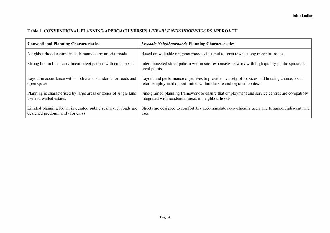
Table 1: CONVENTIONAL PLANNING APPROACH VERSUS LIVEABLE NEIGHBOURHOODS APPROACH
Conventional Planning Characteristics Liveable Neighbourhoods Planning Characteristics
Neighbourhood centres in cells bounded by arterial roads Based on walkable neighbourhoods clustered to form towns along transport routes
Strong hierarchical curvilinear street pattern with culs-de-sac Interconnected street pattern within site-responsive network with high quality public spaces as focal points
Layout in accordance with subdivision standards for roads and open space
Layout and performance objectives to provide a variety of lot sizes and housing choice, local retail, employment opportunities within the site and regional context
Planning is characterised by large areas or zones of single land use and walled estates
Fine-grained planning framework to ensure that employment and service centres are compatibly integrated with residential areas in neighbourhoods
Limited planning for an integrated public realm (i.e. roads are designed predominantly for cars)
Streets are designed to comfortably accommodate non-vehicular users and to support adjacent land uses

Introduction
Page 5
1.3 Town and Neighbourhood Structuring Typically, at the subregional level, around seven neighbourhoods will cluster around a town centre. Each neighbourhood is shown as a circle with an area of around 50 hectares (400-metre radius). Towns are focussed around rail stations, if available, in line with the WAPC’s Policy Number DC 1.6, Development near Metropolitan Railway Stations. The neighbourhood centres are located on crossroads of relatively important streets in order to accommodate through traffic and neighbourhood bus stops and help support local corner stores and community facilities. Neighbourhood centres are connected to each other, the town centre and adjacent centres via ‘Neighbourhood Connector’ streets on which bus routes are located (refer to Figure 1). Primary schools, large areas of parkland and bushland are generally located at the periphery of neighbourhoods so as to contain the neighbourhoods, and also not disrupt them. High schools are generally located along arterial routes to provide a high degree of accessibility and public transport access. A variety of lot sizes is promoted through increasing densities at town and some neighbourhood centres, and adjacent to high amenity areas such as parks. Business and home-based business development opportunities are allocated thus: industrial uses adjacent to freeways, commercial uses along arterial routes and railways, offices and retail uses in town and neighbourhood centres, and home-based business along arterial and neighbourhood connector routes and rail lines.
1.4 Link between Urban Design and These Traffic Management Guidelines
The design of an area at a town scale (also called subregional or district structure) fixes many important elements of a development including the principal streets and town and neighbourhood centres. This high-order structure also sets the framework for the layout of the local street network and pattern of street blocks. The objectives of urban design overlap the priorities of traffic management at this point. They require integration to achieve a design that meets both needs. Table 2 provides a guide to issues of concern to urban designers and traffic engineers. They are described under the three design categories on which these guidelines are based: street layout, street cross section design and intersection control. All three design categories overlap and interrelate. For example, a street layout that encourages high travel speed through long leg-lengths will require more management of the street design for traffic calming and possibly a different approach to intersection control such as a roundabout instead of stop/give way control on the minor approaches. For this reason close liaison between urban designers and traffic engineers is encouraged at the design stage of the land development process. The guidelines that follow in Chapters 2 to 6 provide specific information on appropriate design and illustrate how the three design elements interrelate. The reader is also urged to review Appendix A which provides concise notes on the process of investigating transport and land use issues and designing the Movement Network in concert with all other community elements.

Introduction
Page 6
1.5 Diagrams in these Guidelines Diagrams within this document are mainly derived from case studies and have been altered to emphasise principles and practice promoted in these guidelines. The subregional structuring inherited from these case studies may have benefited from some adjustments to arterial roads or rail alignments to meet Liveable Neighbourhoods Design Element 1: Community Design more completely. The diagrams are thus not intended to demonstrate ideal subregional structuring but rather the principles of street layout, street cross section design and intersection control to achieve the traffic management objectives of Liveable Neighbourhoods Design Element 2: Movement System.
1.6 Street Type Terminology Liveable Neighbourhoods and this document use street type terminology that differs from the Metropolitan Functional Road Hierarchy (Main Roads, 1997) and that adopted in the Western Australian Planning Commission Policy Manual: Development Control (WAPC, 1998). The Glossary at Appendix C provides further information on particular street types in both systems. The terms chosen in Liveable Neighbourhoods are used to emphasise the function of streets for non-car users and to describe support for adjacent land uses. They also emphasise the differences in function and design compared to conventional practice. The use of this terminology will be reviewed along with the review of Liveable Neighbourhoods.

Introduction
Page 7
Table 2: URBAN DESIGN AND TRAFFIC MANAGEMENT
Urban Design Traffic Management Street layout: Activity centres with high level of accessibility. Locate Neighbourhood and Town centres on important streets. Walkable communities. Street blocks generally in the range of 70 metres wide by 120–240 metres long. Shorter blocks at town and neighbourhood centres. Energy efficiency and site responsiveness. Orientation of blocks for solar access or to relate to a topographical or natural feature.
T H E
D E S I G N
Street layout: Provide accessibility without through traffic problems. Network design using a hierarchy of streets based on movement and access functions. Limit attractiveness of access streets to through traffic by controlling length, directness and connectivity. Network design yielding suitable intersection spacing and intersection configuration (i.e. T-junction versus 4-way). These should match the desired street environment and the intersection control methods .
Street cross section design: Equity for all members of the community. Give priority to the needs of the disabled, pedestrians, cyclists and public transportation as well as cars. Contemplate the adjacent land-uses and access needs. Consider human scale and use appropriate features to enhance streetscape.
I N T E R F A C E
Street cross section design: Control traffic speed through appropriate street design and manage conflicts at driveways using access management techniques. Specify appropriate paved width, verge, walkways, street trees, medians, parking embayments, etc.
Intersection control: Consider vehicle, cyclist and pedestrian safety and access needs as they relate to the adjacent land uses. Recognise the impact of intersection control type on space requirements and built form.
Intersection control: Manage conflicting movements safely and with acceptable level of service (delay). Match intersection control method (i.e. priority, roundabout, or signal control) to the type of intersection and user mix (arterial/arterial, arterial/local street, etc).

Street Layout Guidelines
Page 8
2.0 STREET LAYOUT GUIDELINES
2.1 Introduction Street layout is the key to controlling the form of the Movement Network and influences several key features, each of which are covered in this chapter: ❏ Connections between the local street system and the arterial
system; ❏ Layout of Neighbourhood Connectors; ❏ Intersection configurations (T-junctions versus 4-way
intersections) along Neighbourhood Connectors; and ❏ Layout of Access Streets. Please refer to Figure 1 and Figure 2 which illustrate the relationship between the various components of the Movement Network and the associated land uses. Figure 1 shows realistic design features and Figure 2 provides a theoretical model to emphasise some key principles.
2.2 Access onto Arterials Spacing between Arterial/Arterial intersections (shown as 1.6 km in Figure 2) will vary with location and will depend in part on acceptable spacing of traffic signals (where they are required). Refer to Chapter 4 ‘Intersection Control Guidelines’ for additional information on traffic signals. Although Liveable Neighbourhoods promotes an interconnected system of streets to disperse traffic loads, access management on the arterial system is important to safety and efficiency of movement. For this reason, intersection frequency should not be any greater than is necessary to serve local access needs.
Table 3 of Liveable Neighbourhoods identifies 150 metres as the typical average junction spacing on a District Distributor Integrator ‘A’. A ‘left/right’ stagger arrangement of full access T-junctions (as indicated in Figure 3 on page 10 of this document) allows the easiest and safest two-staged crossing of the arterial. This arrangement will benefit local bus routes which use Neighbourhood Connectors. 150 metres is the minimum spacing given in Table 3 of Liveable Neighbourhoods for the ‘left/right’ stagger intersection configuration. This spacing provides for the development of minimum length right turn lanes without overlap. Typical spacing to allow more generous right turn lane length would be 200–250 metres as shown in Figure 3. A ‘right/left’ arrangement is not as favourable for a 2-stage crossing of the arterial, but it does not pose the distance constraint of the overlapping right turn lanes. In most cases, a spacing of 100 metres or greater will allow the junctions to be separated far enough to include a left turn deceleration lane between them. Table 3 of Liveable Neighbourhoods shows the minimum spacing for a ‘right/left’ stagger arrangement as 50 metres on District Distributor Integrator ‘A’ but would not accommodate a left turn deceleration lane.
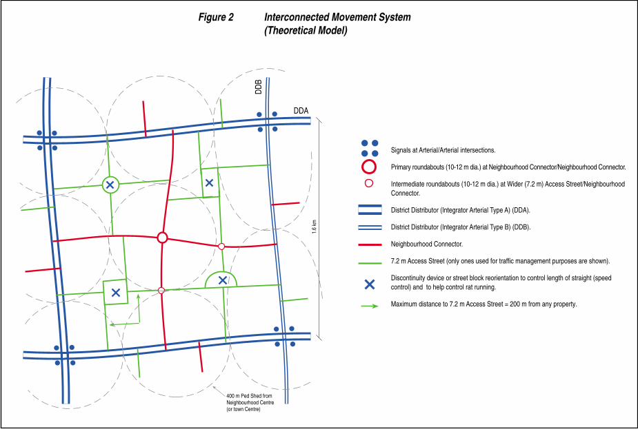
Signals at Arterial/Arterial intersections.
Primary roundabouts (10-12 m dia.) at Neighbourhood Connector/Neighbourhood Connector.
Intermediate roundabouts (10-12 m dia.) at Wider (7.2 m) Access Street/NeighbourhoodConnector.
District Distributor (Integrator Arterial Type A) (DDA).
District Distributor (Integrator Arterial Type B) (DDB).
Neighbourhood Connector.
7.2 m Access Street (only ones used for traffic management purposes are shown).
Discontinuity device or street block reorientation to control length of straight (speedcontrol) and to help control rat running.
Maximum distance to 7.2 m Access Street = 200 m from any property.1.
6 km
DD
B
DDA
400 m Ped Shed fromNeighbourhood Centre(or town Centre)
Figure 2 Interconnected Movement System(Theoretical Model)

The location of the 'town centre' mainstreet intersection with the higherorder Integrator A arterial will bedetermined to some extent by thespacing required between nearbysignals along the Integrator 'A'.
'Ideal' or optimum signal spacing is a functionof road hierarchy type, operating speed andsignal cycle length. If spacing is optimumthen the co-ordination of the 'green' phaseon the arterial minimises delays (for bothdirections of travel) for traffic moving at thedesired operating speed.
It is sometimes necessary to reduce signalspacing along the Integrator 'A' arterial attown centres to cater for the high level ofvehicle and pedestrian activity on the adjacentlocal network.
Buses travelling on NeighbourhoodConnectors and crossing Integrator Arterials atstaggered T-junctions will benefit from 'left/right'stagger arrangement.
This arrangement allows a left turn onto thearterial and a right turn from the arterial to the continuation of the route.
T-junctions will be the norm alongIntegrator Arterials except at intersections controlled by signals or roundabouts.
Buses travelling on Integrator 'B'Arterials will have direct crossingroutes assuming the intersections arecontrolled by signals or roundabouts.
Minimum spacing of full access'Gateways' on arterials is related tolane taper and storage for right turningvehicles. For 60 km/h operatingspeed and 60 metres storage, 200-250 metres is required between'Gateways"
Figure 3 Gateways and Access onto the Regional Road System
TOWNCENTRE
NEIGHBOURHOODCENTRE
NEIGHBOURHOODCENTRE
NEIGHBOURHOODCENTRE
TOWN OR NEIGHBOURHOOD CENTRES
INTEGRATOR ARTERIAL
N
Signals will be required at most 'arterial/arterial' intersections. Town Centres arelocated on Integrator 'B' Arterials near theintersection with Integrator 'A' Arterials.Those intersections will be signalised toaccommodate high vehicle conflicts as wellas pedestrian and cycle movements.

Street Layout Guidelines
Page 11
2.3 Neighbourhood Connectors and Access Streets ‘Neighbourhood Connector’ and ‘Access Street’ identify fundamental functions of the two basic types of local streets. Neighbourhood Connectors must provide relatively direct, convenient connections between Neighbourhood Centres. They also link Neighbourhood Centres to Town Centres. Refer to Figure 1 and Figure 2. Because of their role in transporting people and goods between neighbourhoods, Neighbourhood Connectors operate at higher speeds (60 km/h) and carry more traffic (up to 7,000 vpd) than Access Streets. In terms of the classical dichotomy of ‘Movement versus Access’, these are dual functioning streets because they also provide direct access to fronting properties in most cases.
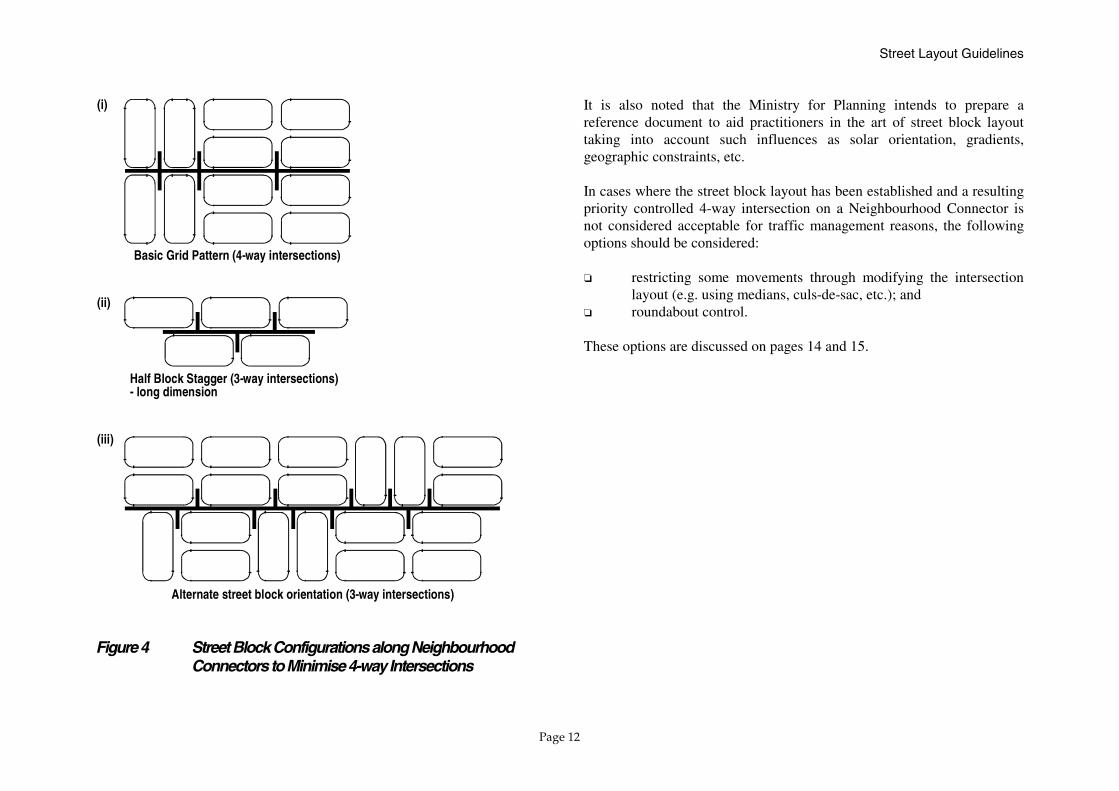
2.4 Managing Intersection Configurations along Neighbourhood Connectors The configuration of street blocks along the Neighbourhood Connector should be done in such a way as to minimise the number of priority controlled 4-way intersections (stop/give way signs on side streets) where possible. This principle follows from the Intersection Control Guidelines (Chapter 4) which urge caution when traffic volumes increase and when speeds increase on the major road. Both of these conditions are possible along Neighbourhood Connectors. Techniques to minimise 4-way intersections along Neighbourhood Connectors include the following (refer to Figure 4 and Figure 5): ❏ Align the long dimension parallel to the street, with blocks on one
side of the Neighbourhood Connector offset by a half block length [refer to Figure 4 (ii)]. This creates a series of staggered T-junctions. If the ‘shift’ is half of a typical 160-metre long block then the resulting T-junction spacing is 80 metres;
❏ Alternate the long and short dimensions parallel to the street.
Block orientations (on both sides of the Neighbourhood Connector) are arranged to give the desired combination of 4-ways and T-junctions [refer to Figure 4 (iii)]. Figure 5 shows how this can be achieved in practice.
Longer blocks can be used midway between Neighbourhood Centres if required to avoid short intersection spacings. The designer should, however, take into account the impact of longer block length on pedestrian access to bus stops. Street block layout behind the Neighbourhood Connector (into the local system of Access Streets) will obviously be strongly influenced by these treatments. A review of the resulting access street layout is then needed to ensure acceptable permeability and legibility for automobiles, pedestrians and cyclists. Please refer to Section 2.5.3 for information on how to achieve a legible network of Access Streets.
Street Layout Guidelines
Page 12
(iii)
Alternate street block orientation (3-way intersections)
Half Block Stagger (3-way intersections)- long dimension
(ii)
(i)
Basic Grid Pattern (4-way intersections)
Figure 4 Street Block Configurations along Neighbourhood Connectors to Minimise 4-way Intersections
It is also noted that the Ministry for Planning intends to prepare a reference document to aid practitioners in the art of street block layout taking into account such influences as solar orientation, gradients, geographic constraints, etc. In cases where the street block layout has been established and a resulting priority controlled 4-way intersection on a Neighbourhood Connector is not considered acceptable for traffic management reasons, the following options should be considered: ❏ restricting some movements through modifying the intersection
layout (e.g. using medians, culs-de-sac, etc.); and ❏ roundabout control. These options are discussed on pages 14 and 15.

LEGEND
Integrator Arterial
Neighbourhood Connector
Access Street
Primary Roundabouts atNeighbourhood ConnectorIntersections
Intermediate 4-ways withRoundabouts if necessary. Additional roundabout not desirable at thislocation if on bus route.
Street blocks arranged to minimise4-ways and position remaining 4-wayat 'intermediate' locations. Mostblocks have 'long' dimension parallel to Neighbourhood Connector.
Note: Natural and man-made features(e.g. drainage channels) break anddeform the interconnected streetsystem.
Figure 5 Street Block Arrangement along Neighbourhood Connectors

Street Layout Guidelines
Page 14
❏ Culs-de-Sac Terminating the road via a cul-de-sac, but continuing the road reserve eliminates the 4-way vehicle operation but retains full pedestrian and cycle access. Obviously this treatment results in redistribution of traffic to adjacent ‘side streets’ and their intersections with more major streets such as Neighbourhood Connectors. It does, however, have the compensating benefit of reducing the number of accesses on the Neighbourhood Connector.
❏ Medians Constructing a median across the intersection effectively converts the intersection into two T-junctions. Full connectivity can be retained for pedestrians and cyclists by providing a narrow gap in the median. A nearby roundabout or median opening will be required to cater for U-turns unless nearby side streets can handle the right turn requirement for automobiles.
Street Layout Guidelines
Page 15
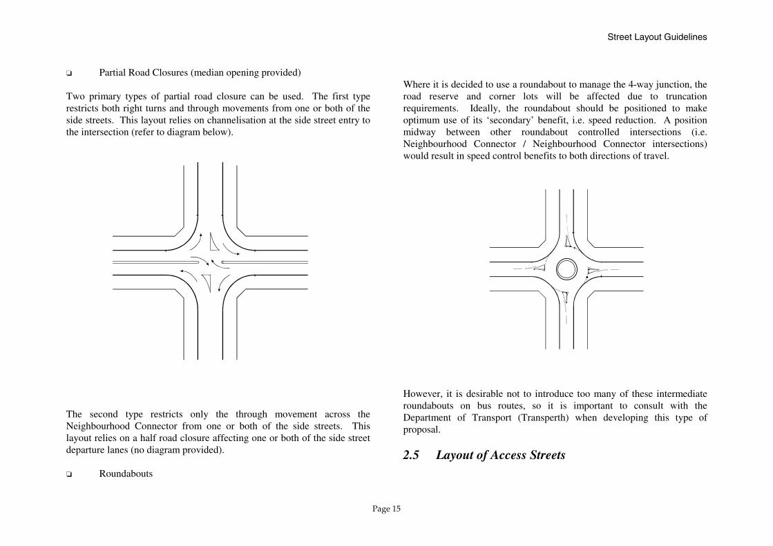
❏ Partial Road Closures (median opening provided) Two primary types of partial road closure can be used. The first type restricts both right turns and through movements from one or both of the side streets. This layout relies on channelisation at the side street entry to the intersection (refer to diagram below).
The second type restricts only the through movement across the Neighbourhood Connector from one or both of the side streets. This layout relies on a half road closure affecting one or both of the side street departure lanes (no diagram provided). ❏ Roundabouts
Where it is decided to use a roundabout to manage the 4-way junction, the road reserve and corner lots will be affected due to truncation requirements. Ideally, the roundabout should be positioned to make optimum use of its ‘secondary’ benefit, i.e. speed reduction. A position midway between other roundabout controlled intersections (i.e. Neighbourhood Connector / Neighbourhood Connector intersections) would result in speed control benefits to both directions of travel. However, it is desirable not to introduce too many of these intermediate roundabouts on bus routes, so it is important to consult with the Department of Transport (Transperth) when developing this type of proposal.
2.5 Layout of Access Streets

Street Layout Guidelines
Page 16
Section 2.5.1 discusses the types of Access Street. Section 2.5.2 covers the layout of Access Streets to control street length and provide for safe priority controlled 4-way intersections. Section 2.5.3 provides some guidance on ways to achieve a legible system of access streets that are by design not in the form of a pure grid (refer also to Figure 6 and Figure 7). 2.5.1 Two Types of Access Streets Access Streets are located within the grid formed by the Neighbourhood Connectors. In these areas, local activity is more dominant and movement by automobile must be geared to low volume, slow speed, access to/from properties in the immediate area with provision for pedestrian and cycle movements of equal priority. Liveable Neighbourhoods envisages the layout of the street network to have: ❏ Wider Access Streets (typical pavement width of 7.2 metres) to
cater for higher traffic volumes and to be located closer to the Neighbourhood Centre, schools and where land use is more intensive and higher densities exist, or where flexibility is required for future conversion to more intensive use or higher density.
Wider Access Streets (7.2 metre pavement width) should also be used for simple and direct linkage to Neighbourhood Connectors from narrower Access Streets. This will reduce driver frustration that may result from very low speed weaving between on-street parked cars. A 7.2 metre Access Street (leading out to a Neighbourhood Connector) should be accessible within approximately 200 metres of any individual property driveway along a 5.5–6.0 metre wide Access Street.
❏ Narrower Access Streets (typical pavement width of 5.5–6.0 metres) are appropriate further away from activity areas,
where volumes are under 1,000 vehicles per day, and where there is a low demand for on-street parking.
2.5.2 Street Length and Safe Priority Controlled Intersections of Access Streets Wider Access Streets (7.2 metres) are important to the layout of the local street system but they can potentially become quite long and continuous. To help control vehicle speed, street length should be limited to less than 350 metres on Access Streets. If the travel routes provided via Access Streets are extremely direct, the potential also exists for ‘rat running’ between Neighbourhood Connectors and Arterials. Please refer to Figure 6 which illustrates through traffic control and speed control concepts for local streets. Network design and street block layout are of crucial importance to provide a discontinuity between neighbourhoods and reduce the potential for ‘rat running’. A number of approaches can be used: ❏ Liveable Neighbourhoods proposes the use of open space, schools
and natural features at the edge of neighbourhoods; and ❏ Street blocks can be re-oriented at the point between
neighbourhoods where the discontinuity is needed to break the through street.

N
Limit the length of 'straight' betweenspeed control devices. Even thoughstreet cross-section design should create an 'environment of care'and result in lower speeds, distances greater than 600 metres may causespeed problems on Neighbourhood Connectors (350 metres on Access Streets).
Limit the continuous length of accessstreets to reduce their attractivenessto 'through traffic'. Shorter 'run up'and a limited visual corridor increase the drivers' expectation for stop/give-way control on the approach to anintersection. This results in fewerinfringements of the signed priority.
'Rat Runs' often 'cut thecorner. Streets should notbe aligned to match these'desire lines'.
Vehicle travel speed will depend on a number of factorsincluding carriageway alignment and width, visual enclosure(street trees and buildings), frequency of side streets andassociated traffic, direct property frontage and drivewayactivity and on-street parking activity.
Speed control treatments suitable for use alongNeighbourhood Connectors include:
Mid-block pedestrian crossings incorporating medianislands (to complement the road narrowing where theembayed parking is removed at the crossing). These'narrowings' should be 'bicycle safe'.
Roundabouts. Neighbourhood Connector/
Blister islands or other horizontal deflection deviceswhich do not detract unduly from the aesthetics of thestreet.
Brick paved intersections help identify the area ofpotential conflict and may be supplemented by splitterislands on the Neighbourhood Connector
In rare cases where arterial through traffic is expectedto be a problem, consideration may also be given toreconfiguring the street layout to introduce a discontinuity into the Neighbourhood Connector. This will reduce thelength of 'straight alignment' between those speed controldevices which can feasibly be incorporated into the traffic management plan.
TOWN OR NEIGHBOURHOOD CENTRES
NEIGHBOURHOOD CONNECTOR
RAIL LINE
Neighbourhood Connector Intersections are the primary candidates. Between these locations, secondarycandidates are 4-way intersections with access streets.When introducing 'intermediate' roundabouts, considerother solutions if the resulting spacing drops below 400metres. Also consult with DOT (Transperth) if the Neighbourhood Connector is to be a bus route.
These features should generally be used to control speedsto acceptable levels. It may be necessary in circumstancesof steep gradient and long straights to supplement thesefeatures with intersection treatment and mid-block speedcontrol devices.
Figure 6 Through Traffic and Speed Control on Local Streets
TOWNCENTRE
NEIGHBOURHOODCENTRE
❑
❑
❑
❑
NEIGHBOURHOODCENTRE
❑

N
LANEWAY
5.5 - 6.0 m ACCESS STREET
7.2 m ACCESS STREET
NEIGHBOURHOOD CONNECTOR
INTEGRATOR ARTERIAL
CUL-DE-SAC
STOP SIGN ON MINOR APPROACH
LOTS WITHIN 400 m WALK OF NEIGHBOURHOOD CENTRE
400 m PED SHED
Wider access streets (7.2 metretypical) provide the innerframework connecting thenarrower access streets. (5.5-6.0 mtypical) to the Neighbourhood Connectors and in some cases toIntegrator Arterials.
70 metre blockwidth and 120-240metre block lengthensures 'finegrained' networkfor high level ofpedestrian andcycle access.
Residential frontage onto this high volumeIntegrator using a rear laneway in this circumstance.
North-South/ East-West orientation forstreet blocks ensures good solarorientation.
Pedestrian/ cycleconnectivity maintainedat these cul-de-sac eventhough automobile access is prohibited.
Figure 7 Street Block Layout and Pedestrian Access
INTEGRATOR ARTERIAL
NEIG
HBO
URHO
OD
CONN
ECTO
R
P. O. S.
70 m
Neighbourhood Centre
Arterial is achieved
Priority control of4-way intersectionis acceptable ataccess streetsprovided that clearindication ofpriority is given todrivers viaintersectiondetailing (e.g.paving, signage,splitter islands,
70 m
etc).
120-
240
m
Street Layout Guidelines
Page 19
Any 4-way intersections of access streets with long ‘run up’ (long uninterrupted approach distance) would have potentially high approach speeds and a high percentage of crossing traffic. These features are likely to increase the frequency and the severity of crashes and should be minimised where priority controlled 4-ways are used. When the street block layout cannot be designed to yield an acceptable priority controlled 4-way intersection, the following may be considered: � Small park or Public Open Space (refer to details below); � Access Street roundabout (6–8 m inner island diameter, refer to
Appendix B, Issue 3); and � Restricting crossing movements by modifying the intersection
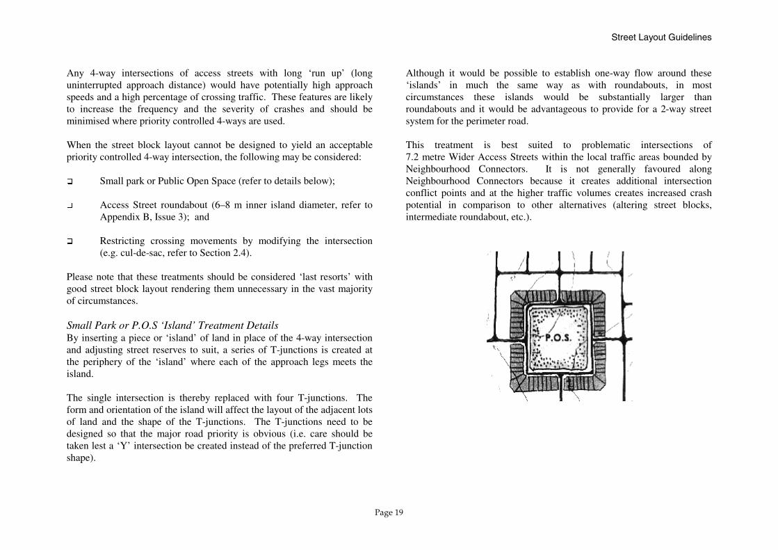
(e.g. cul-de-sac, refer to Section 2.4). Please note that these treatments should be considered ‘last resorts’ with good street block layout rendering them unnecessary in the vast majority of circumstances. Small Park or P.O.S ‘Island’ Treatment Details By inserting a piece or ‘island’ of land in place of the 4-way intersection and adjusting street reserves to suit, a series of T-junctions is created at the periphery of the ‘island’ where each of the approach legs meets the island. The single intersection is thereby replaced with four T-junctions. The form and orientation of the island will affect the layout of the adjacent lots of land and the shape of the T-junctions. The T-junctions need to be designed so that the major road priority is obvious (i.e. care should be taken lest a ‘Y’ intersection be created instead of the preferred T-junction shape).
Although it would be possible to establish one-way flow around these ‘islands’ in much the same way as with roundabouts, in most circumstances these islands would be substantially larger than roundabouts and it would be advantageous to provide for a 2-way street system for the perimeter road. This treatment is best suited to problematic intersections of 7.2 metre Wider Access Streets within the local traffic areas bounded by Neighbourhood Connectors. It is not generally favoured along Neighbourhood Connectors because it creates additional intersection conflict points and at the higher traffic volumes creates increased crash potential in comparison to other alternatives (altering street blocks, intermediate roundabout, etc.).

Street Layout Guidelines
Page 20
2.5.3 Guidelines for Achieving a Legible Access Street Layout The street layout requirements to control through traffic, to limit speeds on local streets and to minimise priority controlled 4-way intersections on Neighbourhood Connectors mean that modified grid street networks of Liveable Neighbourhoods will be less legible than pure grid networks. For this reason, the following guidelines are provided to help achieve a legible modified grid network of streets. 1. Connect internal streets as directly as possible to Neighbourhood
Connectors. The Neighbourhood Connectors form an inherently legible and continuous network of streets that lead to the important community facilities at Neighbourhood Centres and Town Centres.
A useful rule of thumb is to check that no more than three turns
(after turning out of a property driveway) are necessary to get to a Neighbourhood Connector. The idea is that most drivers can track up to three direction changes without getting disoriented.
2. Employ 7.2 metre wide streets to create a direct and legible
internal skeleton from which the remaining access streets (mainly 5.5–6.0 metres wide) can be linked.
Be sure that the search for legibility is balanced with a design that
will help control of vehicle speed and will result in safe intersection configurations.
3. Use community facilities and topographical features (parks,
schools, man-made lakes, etc.) to aid as landmarks within the local traffic areas bounded by Neighbourhood Connectors. Street layouts that create ‘lines of sight’ to these features or have a
consistent orientation in relation to these features will assist drivers in understanding their location.
4. Use reasonably sized street blocks in the layout. Street layouts
which employ small block dimensions (below the typical 70 x 120–240 metre block) may be expensive to develop, result in a lot more intersections, and if not carefully planned, create a confused layout.
Street Cross Section Design
Page 21
3.0 STREET CROSS SECTION DESIGN The typical Access Streets and indicative Neighbourhood Connectors of Liveable Neighbourhoods are shown in Figures 8 and 9. Sections 3.1 to 3.7 provide information necessary to select the appropriate street cross section design. It should be noted that the widths suggested in these Guidelines and in Liveable Neighbourhoods are suggested as appropriate compromises between competing objectives of different disciplines such as urban design and traffic engineering in the local street environment. Where issues may arise with guidelines published by other authorities (e.g. Austroads) or published standards (e.g. Standards Australia) they are noted or discussed in the text. The indicative Neighbourhood Connector cross sections shown in Figure 9 adopt widths narrower than those recommended in the Austroads Guide to Traffic Engineering Practice for a shared bicycle / car parking lane and for a general through traffic lane. The need for this arose from concerns that simply adding together all the Austroads desirable minimum widths resulted in such a wide road that traffic speed would be a problem. In the case of Neighbourhood Connectors the traffic volumes would be limited to a maximum of 7,000 vpd and would generally be less than that, whereas Austroads guidelines have to consider significantly higher traffic volumes as well. The chance of a worst case scenario actually occurring is related to the volumes of vehicles and other road users (e.g. the door of a parked vehicle opens just as a cyclist is passing, with a truck or bus passing at the same time). Thus, the chance of such an event occurring on a Neighbourhood Connector would be significantly less than on the class of roads that Austroads must consider and it is, therefore, considered reasonable to reduce, slightly, some of the clearance distances built into Austroads guidelines.
The Guidelines recommend that Neighbourhood Connectors should be designed with cooperation between traffic engineers and urban designers to suit each circumstance.
3.1 Factors Influencing Street Function and Cross Section
The following factors influence the function of individual streets and are based on the role of the street within the network, the type of land use immediately adjacent to the street, and the prevailing traffic conditions: ❏ Network Connectivity and Street Length; ❏ Bus Route; ❏ Shared Path; ❏ Land Use/Frontage Type; and ❏ Traffic Volumes and Operating Speed. These factors are discussed in turn in Sections 3.2 to 3.7 of this chapter.
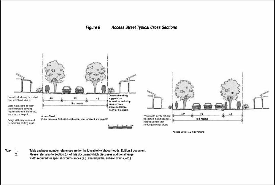
Figure 8 Access Street Typical Cross Sections
Note: 1. Table and page number references are for the Liveable Neighbourhoods, Edition 2 document.2. Please refer also to Section 3.4 of this document which discusses additional verge
width required for special circumstances (e.g. shared paths, subsoil drains, etc.).
Second footpath may be omitted,refer to R26 and Table 2.
Verge may need to be widerto accommodate servicingrequirements (refer Element 6), and a second footpath.
*Verge width may be reduced,for example if abutting a park.
4.0* 5.5 4.5
14 m reserve
Access Street(5.5 m pavement for limited application, refer to Table 2 and page 32)
Access Street (7.2 m pavement)
*Verge width may be reduced,for example if abutting a park.Refer to Element 6 for servicing and verge widths.
4.4* 7.2 4.4
16 m reserve
Common trenchingsuggests 3 m for services excludingtrunk services; allow an additional1.5 m for a footpath.
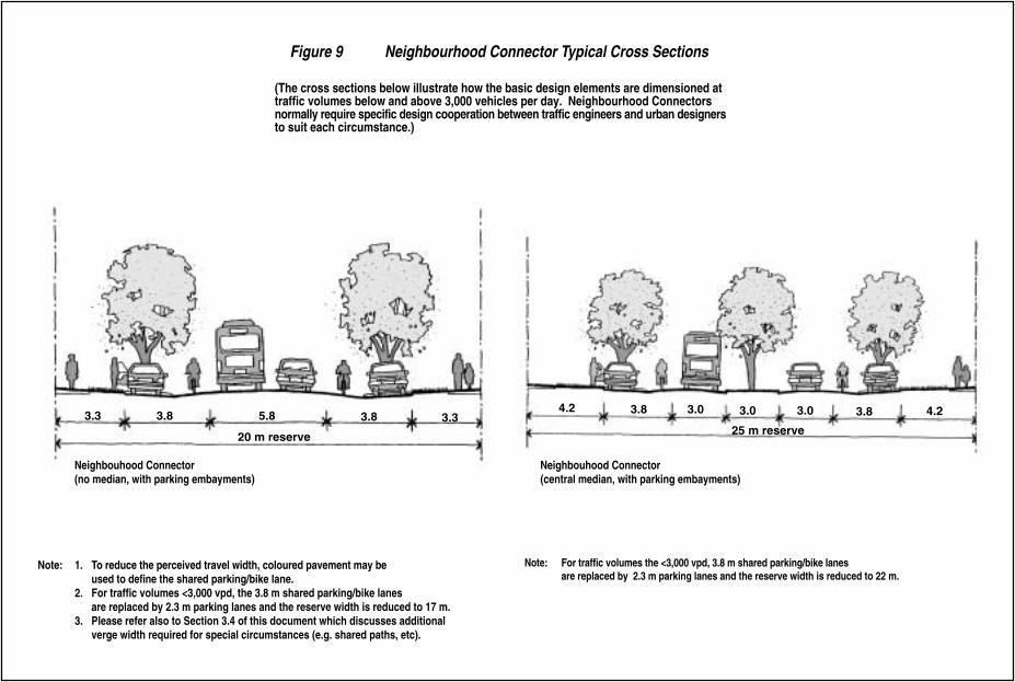
Figure 9
(The cross sections below illustrate how the basic design elements are dimensioned attraffic volumes below and above 3,000 vehicles per day. Neighbourhood Connectorsnormally require specific design cooperation between traffic engineers and urban designers to suit each circumstance.)
Neighbourhood Connector Typical Cross Sections
Note: 1. To reduce the perceived travel width, coloured pavement may be used to define the shared parking/bike lane.
2. For traffic volumes <3,000 vpd, the 3.8 m shared parking/bike lanes are replaced by 2.3 m parking lanes and the reserve width is reduced to 17 m.
3. Please refer also to Section 3.4 of this document which discusses additional verge width required for special circumstances (e.g. shared paths, etc).
Note: For traffic volumes the <3,000 vpd, 3.8 m shared parking/bike lanes are replaced by 2.3 m parking lanes and the reserve width is reduced to 22 m.
3.3 3.8 5.8 3.8 3.34.2 3.8 3.0 3.03.0 3.8 4.2
20 m reserve 25 m reserve
Neighbouhood Connector(no median, with parking embayments)
Neighbouhood Connector(central median, with parking embayments)

Street Cross Section Design
Page 24
3.2 Network Connectivity and Street Length of Access Streets
❏ Narrower Access Streets Short street length and low parking demand would typically be suited to a narrower Access Street. These connect to other Access Streets and to Neighbourhood Connectors. There is room for two moving vehicles to pass or a single moving vehicle to pass a single parked car. The street layout should be such that the distance to a wider Access Street (7.2 metre paved width) should be kept low to reduce driver frustration along these more constrained streets (refer to Section 2.5.1).
Narrower Access Street 5.5–6.0 metre carriageway / 14 metre reserve
❏ Wider Access Streets Wider Access Streets have longer length and usually have connections to Neighbourhood Connectors. Their width provides space for one car to park and two moving cars to pass. Typical street length varies from a single block length at a Neighbourhood Connector to greater than 300 metres where they are used to connect narrower Access Streets.
Wider Access Street 7.2 metre carriageway / 16 metre reserve
3.3 Bus Route Buses will normally travel on Neighbourhood Connectors and Integrator Arterials. It is, however, conceivable that they could be routed on some Wider Access Streets which have reasonable length and/or connectivity, or provide a critical link to a particular destination (hospital, school, sport ground, beachfront). Where buses are expected to run on a street which would otherwise be an Access Street (without embayed parking) the design of the street should be changed to provide a higher standard of mobility. This can be done by employing the following typical cross section:
Access Street with Embayed Parking 10.4 metres / 17 metre reserve
3.4 Shared Paths Footpaths are a standard requirement for all streets in Liveable Neighbourhoods subdivisions (refer to Element 2, Movement Network: R26-R31). Shared paths are designed for use by both pedestrians and cyclists. They are part of the off-road cycling and pedestrian network and often provide important links between local activity points. In some circumstances, the street reserve width must be wider to accommodate them. If a shared path is required, the street verge accommodating the path should be 5.0 (minimum) to 5.5 (typical) metres to cater for the following: ❏ Nearest the kerb: 2.0–2.5 metres (sewer, stormwater, trees/poles);
and ❏ Additional width: 3.0 metres (2.5 metre minimum shared path
plus clearance to obstacles such as walls, trees, etc.). This 3.0 metre space also provides ample space for water, gas, electricity and phone services.
Street Cross Section Design
Page 25
It should be noted that this would affect the standard alignments of street trees and light poles (Utility Providers Code of Practice for Western Australia, 1997) within the verge. The Code of Practice states “Alteration to standard positions may be made only by negotiation between engineers or qualified officers of the authorities concerned”. The need for this negotiation should be recognised. The standard effect of this wider verge requirement in Access Streets is to increase the road reserve width by one metre, assuming the shared path is on one side (and the carriageway is off-centre within the road reserve), as follows:
Access Streets with Shared Paths 5.5–6.0 metre carriageway / 15 metre reserve (up from 14 metres)
7.2 metre carriageway / 17 metre reserve (up from 16 metres) If the sewer/stormwater services are positioned on the opposite side of the street from the shared path or under a parking embayment at the side of the street, and if street lights or street trees are positioned in ‘nibs’ between car bays, this widening is not required. This is because the standard verge can accommodate the shared path without interfering with the other elements. Although non-standard alignments for services will require negotiation for approval, it is reasonable to assume that approval will be forthcoming for Neighbourhood Connectors which have embayed parking. Therefore, a widened road reserve should normally not be required for shared paths on Neighbourhood Connectors unless the non-standard service alignments cannot be successfully negotiated. At the other extreme, if the wider 300 millimetre mountable kerbs are used, and subsoil drains are required on both sides of the street, it is possible that the verge accommodating the shared path would need to be 6.0 metres wide.
The new Australian Road Rules (expected to be introduced in Western Australia later in 2000) will allow cyclists under 12 years old, roller-skaters, skate-boarders, etc. on footpaths unless specifically banned. It seems likely that this will not greatly affect the usage of paths by cyclists in residential streets where current restrictions on cyclists on footpaths are seldom enforced. Therefore it is recommended that Liveable Neighbourhoods requirements regarding path widths should not be altered unless further advice is issued following introduction of the Australian Road Rules.
3.5 Land Use Density/Frontage Type The following cases have been identified for mention: ❏ Residential Frontage – low density (below R25); ❏ Residential Frontage – medium/high density R25 and above; ❏ Mixed Business and Commercial Frontage; ❏ School Frontage; ❏ Beach Frontage; and ❏ Public Open Space Frontage. Low density residential frontage has a ‘low’ on-street parking demand associated with it. Medium/high density residential development has a higher on-street parking demand that is greatest outside of business hours and is typically characterised by low turnover. Please refer to Appendix B, Issue 4 which discusses residential density, parking demand and Access Street width. Mixed business and commercial frontage has a high on-street parking demand during business hours (and outside normal business hours for night time activities such as restaurants, clubs, pubs) and typically has high turnover unless a significant portion is required to serve offices.
Street Cross Section Design
Page 26
School Frontage has a high drop-off/pick-up parking requirement which can sometimes be accommodated in the road reserve with on-street parking only or with a controlled access place/frontage road. In other cases it may not be possible to provide sufficient parking within the road reserve (e.g. due to insufficient road frontage) and additional parking facilities will be required within the school site. Parking turnover is high but demand is very limited to school start and end times. School crossings located on these streets would benefit from 2.0–2.5 metre median islands with grab rails. Shared paths are also often located on one side of these streets and should be considered in the street design mix. Beach frontage has a high parking demand (typically served in part by on-street parking) which peaks on weekends and holidays. Turnover is fairly high (2–3 hours typical). Beach frontage also often accommodates a significant pedestrian crossing demand which benefits from 1.5–2.0 metre median islands connected via painted median lines. Shared paths are also often located on one side of these streets and should be considered in the street design mix. Active recreation P.O.S. (e.g. playing fields) can generate high parking demands, especially on weekends. Passive recreation P.O.S. is less likely to generate significant parking demands. The verge adjacent to P.O.S. frontage can often be reduced where there is no need to accommodate services on that side of the street and where trees and paths can be accommodated within the P.O.S. The impacts of these density/frontage types on typical street cross sections are summarised in Table 3 and illustrated in Figure 10.

Street Cross Section Design
Page 27
Table 3: SPECIAL LAND USE AND STREET CROSS SECTION DESIGN
Special Land Use Frontage Cases and Use of Typical Streets Typical Streets (Carriageway Width / Road Reserve Width)
Residential Medium/High Density (R25+)
Mixed Business / Commercial
School or Beach Frontage
Active P.O.S. Frontage
Access Street 5.5–6.0 m / 14 m
NO (not appropriate)
NO
NO NO
Access Street 7.2 m / 16 m
YES (appropriate)
NO* (parking provision not adequate)
NO* (parking provision not adequate)
YES** (unless embayed parking required)
Neighbourhood Connector 10.4 m / 17 m
YES YES Occasionally, but no median to assist pedestrian crossing movements
YES**
Neighbourhood Connector 13.6 m / 22 m (has 3.0 m median and 2.3 m parking embayment)
YES YES YES YES**
Neighbourhood Connector 13.4 m / 20 m (no median but has 3.8 m wide parking/cycling lane)
YES YES NO (not advisable due to wide paved area and no median facility)
YES**
Neighbourhood Connector 16.6 m / 25 m
YES YES YES YES**
*Note: Access Streets require widening for embayed parking in high demand situations. A 10.4 m street in a 17 m reserve (similar to a Neighbourhood Connector)
may generally be suitable. **Note: The verge adjacent to P.O.S. frontage (and the total road reserve width) can often be reduced.

Figure 10 Street Types, Land Use and Cross Section Design
Roundabout forU-turn at school.
Roundabout forU-turn at school.
street types in an interconnected streetsystem, street design should reflect the
and movement traffic functions, includingdifferent pedestrian, cyclist and on-streetparking circumstances.
Access Streets (7.2 m) typically serveintensity land uses (with higher parking
also can carry more automobilelonger distances. They have a wider
paved surface (kerb to kerb) to betteraccommodate on-street parking withoutsubstantially disrupting traffic movement.Priority given to pedestrians and cyclists isequal to that for automobiles.
On narrower Access Streetspedestrian and cyclist
activity should predominate andautomobile travel should beconstrained.
5.5 - 6.0 m street is conspicuouslynarrower than a 7.2 m street and
correspondingly lower..
volumes are typicallyvery low (well below the 1,000 vpdmaximum) on a narrower AccessStreet(s), the width may be widenedto 7.2 metres to cater for higher on-street parking demand.
Maximum travel distance onnarrower Access Streets (5.5 -6.0 m) before connecting towider Access Streets (7.2 m)should be approximately 200metres.
NEIGHBOURHOOD CONNECTOR
SPECIAL LAND USE CASES
Medium/high density residential zone with on-street parkingdemand. Small setbacks ( below 6 metres) between garages and the property boundary also create higher on-streetparking demand.
Public Open Space frontage has reduced road vergedimension on one-side.
Shops/ community service uses usually require embayedparking along street frontage.
Primary School served by frontage street with embayedparking and/or Controlled Access Place and median. Median prevents mid-block U-turns at drop-off point. Roundaboutscater for U-turn manoeuvres. It is preferable to have at leastthree streets fronting the school to provide adequate access and circulation.
according thespecific user needs at different locations in the network:
On-street parking demand (e.g. embayed parking in
Target traffic volumes and speed (e.g. shared parking/cycle lane is wider above 3,000 vpd for
Pedestrian and cyclist activity along and across thestreet (e.g. shared paths and medians).
Driveway access control (e.g. median to control rightturns on high volume Neighbourhood Connector).
Bus routes (e.g. embayed parking will ensure busembayment is easily incorporated into NeighbourhoodConnector design).
Wider Access Streets (7.2 metres) provide the internal accessstreet framework and link to the Neighbourhood Connectors.
Street cross section design is determined to
commercial precincts).
T
Neighbourhood Connectors).
Although it is harder to differentiate between
intensity of land use and the different access
Wider higher demand). They traffic over
NEIGHBOURHOODCENTRE
(5.5 - 6.0 m),
Although traffic
A
speeds be will
NEIGHBOURHOODCENTRE
❑
❑
❑
❑
❑
N

Street Cross Section Design
Page 29
3.6 Rear Laneways and Associated Street Cross Section Design
This section discusses the appropriate detailing of streets where a rear laneway is also provided. Rear laneways are used as a design treatment in particular circumstances: ❏ When streets have a significant volume of traffic, safer access can
be provided via a laneway or through alternate methods such as shared driveways and increased setbacks;
❏ Laneways provide for rear garaging of cars, avoiding an ugly
‘garage-scape’; ❏ Where narrow lots are employed (e.g. 12 metres with no room for
garages at the front); and ❏ To allow direct frontage to parks to provide surveillance (without
a fronting street). The following cases are presented to illustrate how parking demand is accommodated where rear laneways are used. Case 1: Traffic volumes above 3,000 vpd would typically be required before a rear laneway would be considered as one of several possible frontage management techniques. The resulting Neighbourhood Connector street cross section design includes embayed parking which will cater adequately for visitor and owner parking at the street front. Case 2: The street fronts onto passive P.O.S. and on-street parking demand is only 50% of the typical case (development on both sides of the street). In these circumstances, the narrower Access Street (5.5–6.0 metre paved width) should be adequate unless other factors are at play. For example, the street may be part of a framework of wider Access Streets
and carry a high level of access street traffic, or the P.O.S. may be intended to be used for active recreation such as playing fields which could generate significant parking demand, especially on weekends. Case 3: Home-based business generates visitor parking demand and should have 7.2 metre wide streets as recommended for commercial use cases. Case 4: Remaining cases (i.e. narrow lot frontages without Cases 1 or 2), the density is likely to be R25 or higher thus requiring a 7.2 metre wide Access Street. No parking should be permitted in the rear laneway except in a very few selectively located parking bays. Refer to WAPC Planning Bulletin No. 33.
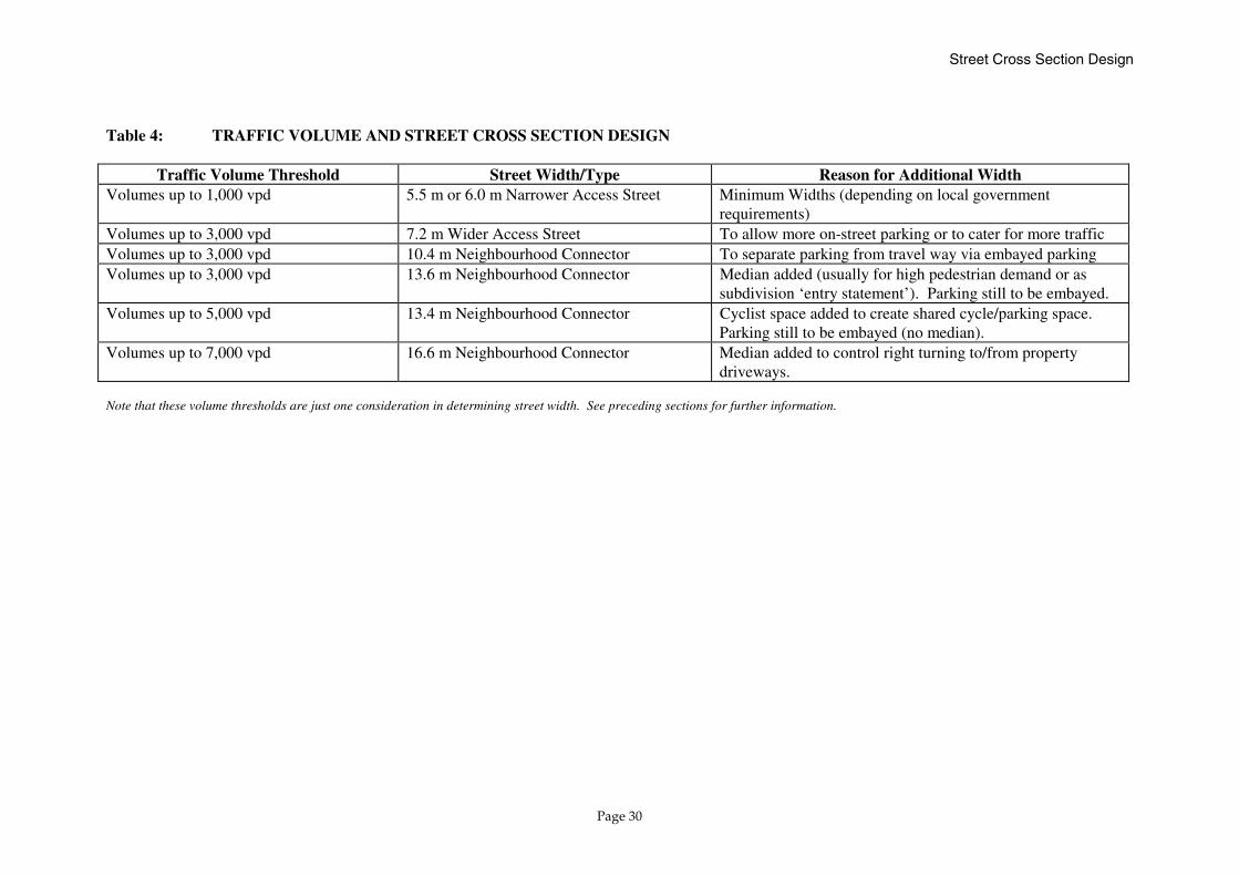
3.7 Traffic Volumes and Operating Speed Traffic volumes influence the movement function of the road and thereby the space provided for moving vehicles versus parked cars and other road users (e.g. cyclists). Table 4 shows that street width increases as traffic increases.
Street Cross Section Design
Page 30
Table 4: TRAFFIC VOLUME AND STREET CROSS SECTION DESIGN
Traffic Volume Threshold Street Width/Type Reason for Additional Width Volumes up to 1,000 vpd 5.5 m or 6.0 m Narrower Access Street Minimum Widths (depending on local government
requirements) Volumes up to 3,000 vpd 7.2 m Wider Access Street To allow more on-street parking or to cater for more traffic Volumes up to 3,000 vpd 10.4 m Neighbourhood Connector To separate parking from travel way via embayed parking Volumes up to 3,000 vpd 13.6 m Neighbourhood Connector Median added (usually for high pedestrian demand or as
subdivision ‘entry statement’). Parking still to be embayed. Volumes up to 5,000 vpd 13.4 m Neighbourhood Connector Cyclist space added to create shared cycle/parking space.
Parking still to be embayed (no median). Volumes up to 7,000 vpd 16.6 m Neighbourhood Connector
Median added to control right turning to/from property driveways.
Note that these volume thresholds are just one consideration in determining street width. See preceding sections for further information.
Intersection Control Guidelines
Page 31
4.0 INTERSECTION CONTROL GUIDELINES
4.1 Introduction This chapter provides guidance on intersection control to suit the various intersections in the Movement Network. The following issues are covered: ❏ Signals on arterials; ❏ Primary and intermediate roundabouts on Neighbourhood
Connectors; ❏ Appropriate traffic control for the different types of intersection
(for both T-junction and 4-way intersections); ❏ Stop/give way control at Access Street intersections; ❏ Guidelines for safe priority control at 4-way intersections; and ❏ Corner truncations and kerb return radii.
4.2 Traffic Control and Intersection Type Table 5 and Table 6 help match the appropriate control method (i.e. signals, roundabout, and stop/give way) to the particular intersection type (refer to Figure 11). Reference should also be made to Draft Code of Practice, Traffic Control Devices published by Main Roads Western Australia (Main Roads) and to AS 1742 Manual of uniform traffic control devices, Part 2: Traffic control devices for general use published by Standards Australia.
4.3 Signals on Arterials Main Roads has control over signal installation and operation in Western Australia. Traffic signal warrants include vehicle volumes, crash history
and pedestrian volumes. Please refer also to Austroads Guide to Traffic Engineering Practice: Part 5, Intersections At-Grade. Proposals that contemplate intersection control using traffic signals should be discussed with Main Roads at an early stage. At the development planning stage it is important to identify existing signal locations and establish appropriate spacing to any new signalised intersections. There are no established spacing guidelines published for use in Western Australia. Austroads Guide to Traffic Engineering Practice: Part 5 (page 10) indicates 350–550m between signalised intersections to facilitate co-ordination, but current practice by Main Roads is to seek greater spacing if possible. When planning the interconnected street system of Liveable Neighbourhoods it is expected that arterial/arterial type intersections will be encountered approximately every 1.5–2.0 kilometres. Between these intersections, circumstances may require an ‘intermediate’ signalised intersection due to traffic volumes and safety issues at Neighbourhood Connector/Arterial intersections. At these ‘intermediate’ signals, T-junction or 4-way configurations will operate safely. At the remaining intersections (un-signalised), 4-ways may operate safely but are not encouraged. Priority controlled T-junctions are expected to be more generally appropriate. Please refer also to Chapter 2, Street Layout Guidelines that discuss access onto arterials.

Intersection Control Guidelines
Page 32
Table 5: TRAFFIC CONTROL AT 4-WAY INTERSECTIONS
Intersection Type Signals Roundabout Stop/Give Way Arterial/Arterial Yes Yes (high capacity roundabout in low pedestrian/
cyclist activity environment) No
Arterial/Neighbourhood Connector (Few 4-ways at these junctions)
Yes (if warrants are satisfied)
Yes, if signal co-ordination is not important, but inappropriate if there are significant pedestrian flows
No
Neighbourhood Connector / Neighbourhood Connector
No Yes (10–12 m inner island diameter designed for slow speeds is more suitable for pedestrians/cyclists)
Rarely (refer to special guidelines in Section 4.6)
Neighbourhood Connector / Access Street (Special intersection control review required)
No Occasionally, for speed control and intersection safety on Neighbourhood Connectors (refer to Section 4.4)
Yes (refer to special guidelines in Section 4.6)
Access Street / Access Street No Rarely (refer to Appendix B, Issue 3) Yes Table 6: TRAFFIC CONTROL AT T-JUNCTIONS
Intersection Type Signals Roundabout Stop/Give Way Arterial/Arterial Yes Yes (high capacity roundabout and low pedestrian/
cyclist activity) No
Arterial/Neighbourhood Connector (Few 4-ways at these junctions)
Occasionally (if warrants are satisfied)
Yes, if signal co-ordination is not important, but may not be appropriate if there are significant pedestrian flows
Yes, depending on volumes and nearby signals as alternative access
Neighbourhood Connector / Neighbourhood Connector
No Yes (10–12 m inner island diameter). Used for speed control benefits even if volumes are acceptable
Yes, but can use roundabout control where speed control is needed on major street
Neighbourhood Connector / Access Street
No Occasionally, for speed control and intersection safety on Neighbourhood Connectors (refer to Section 4.4)
Yes
Access Street / Access Street No Rarely (refer to Appendix B, Issue 3) Yes

N
Signals will be used at mostintersections of Arterials. In some cases, high capacity roundabouts (e.g. inner islanddiameter 20 m +) will be usedbut these are not suitable inareas of high pedestrian and cyclist activity (e.g Town Centre).
Figure 11 Intersection Control to Match Intersection Type
Inte
grat
or '
A'Integrator 'B'
Priority control (give-way/stopon the minor leg) isappropriate for most if not all4-way intersections of Access Streets if leg lengths (run up)are kept short.
4-way intersections between AccessStreets and Neighbourhood Connectorswill require special evaluation to ensuresafe priority control operation. Trafficvolumes including the percentage oftraffic crossing the NeighbourhoodConnector will influence the appropriatecontrol method. If unsafe, considerationshould first be given to changing the street block layout. Refer to Section 2.4and 4.6.
LOCAL TRAFFIC AREA SERVED BY ACCESS STREETS
NEIGHBOURHOOD CONNECTOR
INTEGRATOR ARTERIAL
SIGNALS
(10-12 m INNER ISLAND DIAMETER) ROUNDABOUTS
Smaller roundabouts (inner islanddiameter 10-12 m) will be used at most4-way intersections of Neighbourhood Connectors. Priority control will besuitable for most of the 3-way intersections of the NeighbourhoodConnectors.

Intersection Control Guidelines
Page 34
4.4 ‘Primary’ and ‘Intermediate’ Roundabouts on Neighbourhood Connectors As mentioned in Chapter 2 and as shown in Table 5 and Table 6, the junctions of Neighbourhood Connectors should be controlled with roundabouts in most cases. These are termed ‘primary’ roundabouts under the theoretical model illustrated in Figure 2. ‘Intermediate’ roundabouts may be used to safely manage a 4-way junction in between the ‘primary’ roundabouts and, at the same time, provide a speed control benefit on the Neighbourhood Connector. The ‘intermediate’ roundabouts are also identified in the theoretical model illustrated in Figure 2. However, this frequency of roundabouts may not be desirable if the Neighbourhood Connector is to be used for a bus route. It is therefore important to liaise with the Department of Transport (Transperth) during subdivision design to avoid objections during the subdivision approval process. Whenever possible, roundabouts should be used primarily to manage traffic conflicts and only in a secondary capacity to solve speed control problems. The inappropriate use of roundabouts as a ‘cure all’ is not favoured due to the additional land requirements, the additional cost, and in the instance of bus routes, the negative effect on bus passenger comfort.
4.5 Stop/Give Way at Access Street Intersections As illustrated in Figure 11 and in Table 5 and Table 6, priority control (stop/give way on the minor leg) is appropriate for nearly all intersections of access streets. Only when street block layout cannot be configured to limit ‘run up’ on the side street, should roundabout control or movement restrictions be considered at access street / access street intersections. Long uninterrupted ‘run-up’ (i.e. >300–400 m) on the side street may lead to higher speeds
and, depending on connectivity, may be associated with a higher percentage of ‘crossing’ movements at 4-ways. Street block layout changes should be used in the first instance to eliminate the long ‘run-up’. Alternatively, a small roundabout (inner island diameter of 6 to 8 metres) may be considered. Some options for the restriction of movements at a 4-way intersection (e.g. closure of one leg to form a cul-de-sac, construction of a median across the intersection to restrict crossing and right turning traffic, and partial road closures) are discussed on pages 14 and 15. Such options have the disadvantage of reducing legibility and permeability of the road network for motorists and result in less dispersal of local traffic flows across the street network. However, these treatments may be appropriate to treat particularly difficult 4-way intersections where safety is of concern. When such treatments are being considered particular care should be taken to avoid treatments that unduly restrict movement to and from town and neighbourhood centres, schools, railway stations, etc. Again, restraint is urged in the use of roundabouts and movement restrictions at intersections of access streets, as they should rarely be required if the street layout is done properly. Each of these treatments is also likely to increase land requirements for the intersection (e.g. larger truncations, localised widening of road reserves, land for cul-de-sac head) and will require more detailed design of individual cases.

Intersection Control Guidelines
Page 35
4.6 Guidelines for Priority Controlled 4-way Intersections
These are performance based guidelines for all intersection types where 4-way priority control is to be considered (e.g. Neighbourhood Connector/ Access Street and Access Street / Access Street intersections). Fundamental principle: 4-way intersections must operate safely with acceptable delay. ❏ Issue 1 Many safety problems relate to mistaken understanding of priority at the junction. ❏ Strategy
Make clear the priority operating at the junction (i.e. identify visually which is the major versus minor approach).
− Control the ‘run up’ length on the minor leg approach to reduce
driver expectation for priority at the junction; − Establish highly visible stop / give way signs and pavement
markings; − Consider brick paving at the intersection threshold on the minor
leg where needed to supplement the above treatments; − Ensure that sight distance is adequate for the applicable design
speed on the through road; and − In select cases consider aligning the minor street approach so that
the view corridor is interrupted at the junction. Note: Sometimes the whole intersection is brick paved to increase general awareness of the intersection and the need for caution. ❏ Issue 2
Gap selection becomes more difficult as conflicting volumes increase. Crash rates therefore increase as the conflicting minor/major approach volumes increase. ❏ Strategy Establish volume related limits for 4-ways to use in conjunction with other
decision criteria. Although no references could be found setting out safety related volume thresholds, after discussion with a number of Western Australian and eastern states traffic engineers during the preparation of the Guidelines, the consultants have suggested that the ‘threshold’ is in the range from 2,000 vpd to 5,000 vpd total intersection traffic. This should be treated as a ‘rule-of-thumb’ only. Note that crash rates also increase with an increase in the percentage of crossing movements. Lower thresholds may be needed for higher crossing movement potential. Please refer also to Section 2.4, ‘Managing Intersection Configurations along Neighbourhood Connectors’. ❏ Issue 3 Crash severity increases with increasing speeds and with increasing number of crossing movements from the minor approaches. ❏ Strategy
Consider the speed environment on the major road and the number of crossing movements when assessing priority controlled 4-ways.
Speed management is important along Neighbourhood Connectors in particular due to their length and the potential for higher speeds. Regardless of whether priority controlled T-junctions or 4-ways are used,
Intersection Control Guidelines
Page 36
splitter islands and grab rails can be used on the Neighbourhood Connector to highlight the intersection to the driver and enforce an environment of care. The number (or percentage) of crossing movements may be difficult or impossible to ascertain at the planning stage. Rather, an analysis of ‘desire lines’ is more likely to yield the qualitative appreciation for the potential crossing activity from the minor street ‘across’ the Neighbourhood Connector. Typical desire lines that are relevant relate to trips for the following purposes: ❏ Home to work: (Is there a short cut available through the access
street system?); and ❏ Home to schools and neighbourhood shops: (Does the access
street lead directly to a school or neighbourhood shop across the Neighbourhood Connector?).
Conclusion: The Access Street / Access Street locations are deemed generally safe for priority controlled 4-ways. This assumes that the Access Street network has been configured to control the traffic volumes, the traffic speeds, and the ‘run up’ at these intersections. A traffic management assessment should confirm that the street layout is appropriate before approving priority controlled 4-ways in these locations. Although 4-ways are generally to be minimised on Neighbourhood Connectors, they will operate safely in some circumstances. For those cases where priority 4-ways are proposed on Neighbourhood Connectors, they should be reviewed against these performance criteria.
4.7 Corner Truncations and Kerb Return Radii at Intersections Corner truncations can influence sight lines of automobiles, pedestrians and cyclists at intersections. They can also affect the ability for stormwater and other services to be appropriately aligned or positioned at intersections. In conjunction with kerb return radii they also affect the width of the footpath at street corners. Kerb return radii influence the swept path of vehicles executing turns at intersections and the speed at which those turns are made. Liveable Neighbourhoods promotes lower automobile travel speeds in the local street system and ease of pedestrian movement at crossings. A balance is thus required which provides adequately for all road users as well as allowing for the necessary services within the road reserve. Appendix B documents the results of the technical investigation into these issues. The conclusions are summarised here. 4.7.1 Corner Truncations Corner property truncations of 3 x 3 metres are required as the default truncation in the local street network. At the intersection of rear laneways and streets, a 2 x 2 metre truncation is required as the default (where a footpath is located close to the property boundary in the road verge). Please refer to WAPC Planning Bulletin No. 33. An alternative which may be considered is to narrow the laneway width (to a single travel way) at the junction with the Access Street. This requires traffic to slow and reduces or eliminates the need for the truncation at the laneway.
Intersection Control Guidelines
Page 37
Please note that truncation requirements for intersections along arterials are not covered here. Consult with the relevant transport and land use planning authorities to determine these requirements. Specific situations (e.g. road geometrics, narrow frontage lots, etc.) may give rise to the need to make exceptions to the default truncation rules. For example, an acute angle of intersection between two streets may require an increase in the default truncation. On the other hand, a reduction to the default truncation may be justified to improve the viability of narrow frontage lots where services will not be affected and footpath use is low to moderate. These cases are to be handled through a request for variation of the standard at the detailed design stage. Please refer to Appendix B for more information. 4.7.2 Kerb Return Radii A 6-metre kerb return radius is the default at Access Street / Access Street intersections. This caters for the B99 design car (turning radius 6 metres) using the correct side of the pavement only (Figure B1 in AS 2890.1, 1993). It also caters for the design heavy rigid vehicle (turning path radius 11 metres), using any part of the pavement (Figure B4 AS 2890.2, 1989). A 9-metre kerb return radius is the default at Access Street / Neighbourhood Connector intersections. This caters for the design heavy rigid vehicle (turning path radius 11 metres), using any part of the pavement (Figure B4 in AS 2890.2, 1989). Note that the use of central median splitter islands at intersections restricts the width of road pavement available for heavy vehicles to turn and will often require larger kerb return radii. Kerb radii at Neighbourhood Connector / Neighbourhood Connector intersections will depend on
roundabout design requirements but should be kept to the minimum necessary to control the speed of left turns, which often pose problems for pedestrians. Intersections along arterial routes should be designed to cater for articulated vehicles. Please refer to Appendix B for more information.
Integrated System Performance Review
Page 38
5.0 INTEGRATED SYSTEM PERFORMANCE REVIEW
The following checklist is provided to assist those undertaking design and review of Liveable Neighbourhoods developments. It focuses on the three fundamental features, namely street layout, cross section design and intersection control.
5.1 Street Layout Performance ❏ Arterial System is adequate to serve the site, and access points
(gateways) are determined with signal spacing and un-signalised T-junction spacing in mind.
❏ Neighbourhood Connectors directly link Neighbourhood Centres
to each other and to Arterial ‘gateways’. ❏ Neighbourhood Connectors and Access Streets provide excellent
pedestrian and cyclist accessibility to all local destinations. ❏ Bus routes are highly accessible from residential areas and
connect to Neighbourhood Centres, Town Centres, District Recreation Facilities, Education Facilities, Rail Stations, etc.
❏ Potential through traffic routes are checked and necessary
discontinuity treatments are designed into the layout. ❏ Speed management needs are identified on the longer streets and
street layout changes are considered in lieu of traffic management devices.
5.2 Street Cross Section Suitability ❏ Intended street function is understood in terms of predicted type,
volume and speed of traffic, and the needs of other road users (pedestrians, cyclists, access parking).
❏ Street road reserve widths suited to street trees, walkways, bus
routes, on-street parking, traffic volumes and access management features (e.g. median).
❏ Street paved width suited to traffic and parking and public
transport and cyclist needs.
5.3 Intersection Configuration and Control ❏ Signals limited to the arterial system in nearly all cases. ❏ Neighbourhood Connector / Neighbourhood Connector
intersections served by ‘primary roundabouts’ in most cases. ❏ Priority controlled 4-way intersections minimised on
Neighbourhood Connectors. ‘Intermediate’ roundabouts considered for safe treatment of 4-way intersection midway between ‘primary’ roundabouts (but should not be overused on bus routes).
❏ 4-way priority controlled junctions checked for:
− Run up length (i.e. avoid long, uninterrupted approach distance on the side street);
− Desire line across the major street; − Major road / minor road volume thresholds; and − Speed environment on the major road.
Integrated System Performance Review
Page 39
❏ Street junction spacing checked for suitability against requirements in Liveable Neighbourhoods.
5.4 Examples of Traffic Management Plans Figure 12 illustrates the information necessary to document the intended street hierarchy as well as the street cross sections which are suited to the network and the land uses. Figure 13 illustrates the intersection control and speed management devices that are required to supplement the street layout and design features. Note that these plans are not templates that resolve every issue. The design team of planners, engineers, urban designers, etc. needs to work together, enquiring by design, refining the concept plan and, where necessary, agreeing to compromise their differing viewpoints so as to achieve an holistic solution that is greater than the sum of their individual specialisations.
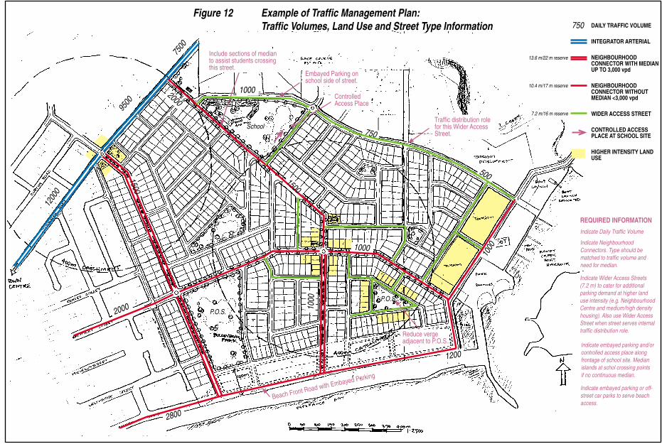
13.6 m/22 m reserve
10.4 m/17 m reserve
7.2 m/16 m reserve
REQUIRED INFORMATION
Indicate Daily Traffic Volume
Indicate NeighbourhoodConnectors. Type should bematched to traffic volume andneed for median.
Indicate Wider Access Streets(7.2 m) to cater for additionalparking demand at higher landuse intensity (e.g. NeighbourhoodCentre and medium/high densityhousing). Also use Wider AccessStreet when street serves internaltraffic distribution role.
Indicate embayed parking or off-street car parks to serve beachaccess.
DAILY TRAFFIC VOLUME
INTEGRATOR ARTERIAL
NEIGHBOURHOODCONNECTOR WITH MEDIANUP TO 3,000 vpd
NEIGHBOURHOODCONNECTOR WITHOUTMEDIAN <3,000 vpd
WIDER ACCESS STREET
CONTROLLED ACCESSPLACE AT SCHOOL SITE
HIGHER INTENSITY LAND
Indicate embayed parking and/orcontrolled access place alongfrontage of school site. Medianislands at schol crossing pointsif no continuous median.
1200
Reduce vergeadjacent to P.O.S..
Beach Front Road with Embayed Parking
1000
9500
2000
7500
750
500
1000
1000
2800
1000
1200
0
2000
Figure 12 Example of Traffic Management Plan:Traffic Volumes, Land Use and Street Type Information
Embayed Parking onschool side of street.
Controlled
Include sections of medianto assist students crossing
P.O.S.
P.O.S.
1500
750
Traffic distribution rolefor this Wider AccessStreet.
Access Place
this street.
USE
School
1500

Figure 13 Example of Traffic Management Plan:Intersection Control and Speed Management Information
ROUNDABOUT
STOP/GIVE WAY ONMINOR APPROACHAT 4-WAY
LEFT IN/LEFT OUT
DEFLECTED 'T'
100 m
CUL-DE-SAC
Appendix A – Movement Network Design Process
Page 42
Appendices APPENDIX A - MOVEMENT NETWORK DESIGN PROCESS This section provides some brief notes on the process of investigating transport and land use issues and designing the Movement Network in concert with all other community elements. Although it is difficult to show here, it is important to recognise that the design process involves iteration between the following design levels: ❏ Regional and Subregional Context; and ❏ Site Layout. Regional and Subregional issues are covered here but the major focus is on the site related issues of street layout, street design, and intersection control. Section headings are as follows: ❏ Regional Context Analysis; ❏ The Site in Subregional Context; ❏ Analysis of the Arterial Grid System; ❏ Local Street System and Local Land Use Structure; and ❏ Intersection Control and Speed Management. Regional Context Analysis Reference should be made to all relevant Regional Strategies and Structure Plans, and District Structure Plans as well as specific transport and land use studies undertaken in the region. On the transport side, the Perth Bicycle Network Plan, the Strategic Freight Network Maps, the Perth Metropolitan Road Hierarchy Plan, and the 10 Year Better Public Transport Plan should be reviewed. Outside of the Perth Metropolitan Area, any plans equivalent to the above should be reviewed.

Appendix A – Movement Network Design Process
Page 43
On the land use side, the Metropolitan Region Scheme (or other statutory region schemes for other areas), Metro Centres Policy, and Local Planning Strategies (Town Planning Schemes) should be reviewed for relevant information. ❏ Transport System, Existing and Planned The focus should be on the Primary and District Distributors (Integrator Arterials) and the rail alignment and station locations relative to important urban nodes such as town centres. Regional bicycle routes, freight routes, and bus routes should be reviewed. ❏ Land Use, Existing and Planned The focus should be on the major land use features including key employment and commercial centres. These may provide the opportunity to favourably locate higher density close to key transport services to support public transport and reduce travel by car. Identify significant travel desire lines to destinations in surrounding areas (e.g. regional/district level employment, shopping, education, and recreation facilities) so that transport links can be matched to these routes. Site in Subregional Context The investigation should now shift to the site, its preliminary structuring and the relationship to nearby transport and land use features. Reference should be made to more detailed site specific policies, strategies or studies that may influence the site (e.g. nearby Outline Development Plans, a Local Housing Strategy, etc.). A finer level of detail is provided and the relationship of schools, parks, local community facilities, local town centre, local industrial uses, and residential areas is highlighted.
❏ Transport System, Existing and Planned Neighbourhood Connectors are added to the Movement Network and access points are identified along Integrator Arterials. In some cases the ‘arterial grid’ may not be suitable and changes may be needed to serve the site adequately. Refer to the specific details identified in ‘Analysis of the Arterial System’. ❏ Land Use, Existing and Planned Important features include the Neighbourhood Centre and Town Centre Locations, areas for mixed business and home business development, and areas near public transport stations or routes for higher density development. Industrial uses need to be located with reference to the Movement Network and may provide buffering between residential areas and rail lines and roads with very high traffic volumes (e.g. freeways). Analysis of the Arterial System Background information should be documented to assist in understanding the arterial system serving the area (i.e. Primary Distributors and District Distributor Integrator Arterials Type A and Type B). ❏ The existing and proposed road hierarchy should be documented.
This will identify the intended function of the roads and will assist in identifying likely operating conditions, possible frontage development opportunities or constraints and responsible access management.
❏ Existing and proposed traffic volumes, traffic speeds (or speed
limits), road cross sections, and intersection location points should be identified.

Appendix A – Movement Network Design Process
Page 44
❏ Confirm that the existing and/or planned arterial system adequately serves the site and identify any improvements needed. Provide feedback to the various regional transport and land use authorities to discuss any changes. Be sure to look beyond the boundaries of the site to integrate the road network planning with adjacent sites.
Local Street System and Local Land Use Structure i. Neighbourhood Connectors Neighbourhood Connectors are a primary structuring element of the Movement Network. Some key features are identified below: ❏ Neighbourhood Connectors: Gateways to the arterial system In almost every case, the main link between the local and the
regional movement system is made via a Neighbourhood Connector. Access Street intersections with District Distributors are likely to have limited movements (e.g. left in / left out only) or may be priority controlled T-junctions. This is because of the need for access control along the arterial system and the desire to manage traffic within the local street system. Review the layout of Neighbourhood Connectors to ensure that they provide legible and direct linkages from the arterial ‘gateways’ to nearby Neighbourhood Centres.
❏ Neighbourhood Connectors: Providing direct links to and between
Neighbourhood Centres
This is the second key layout requirement for Neighbourhood Connectors. Figure 1 (Movement Network and Subregional Context) and Figure 2 (Theoretical model of the Movement Network) show that a grid-like pattern of Neighbourhood Connectors should be achieved.
❏ Neighbourhood Connectors: Providing good bus routes This is a performance requirement which should be automatically
satisfied if Neighbourhood Centres are linked to each other and to the arterial ‘gateways’.
The location of ‘gateways’ will influence bus routes using
Neighbourhood Connectors. This influence is greatest at the interface with arterials where routes will sometimes be required to follow a ‘staggered’ alignment across the arterial if the Neighbourhood Connector intersection is not a signalised 4-way intersection.
Where the ‘staggered’ alignment is required, T-junctions in a
‘left/right’ stagger configuration is preferred. This arrangement reduces delay and increases safety for buses and other traffic crossing the arterial.
❏ Neighbourhood Connectors: Limiting ‘arterial’ through traffic
If intersections on the arterial system become seriously congested, there is potential for regional traffic to seek alternative routes or ‘rat runs’ to avoid the delay.
Neighbourhood Connectors and Access Streets should not offer attractive alternatives to cut across the arterial grid. The standard street design, parking activity around the Neighbourhood Centres and the presence of primary and some intermediate roundabouts

Appendix A – Movement Network Design Process
Page 45
on the Neighbourhood Connectors should reduce the attractiveness to ‘through traffic’. In some circumstances, it may be necessary however to introduce some discontinuity into the Neighbourhood Connector alignment to further discourage through traffic.
❏ Neighbourhood Connectors: Opportunities for increased
residential density and home-based or mixed business
Along bus routes and particularly at locations closer to Neighbourhood or Town Centres, there may be scope to increase residential density and/or to provide mixed zoning to facilitate small businesses along some Neighbourhood Connectors.
❏ Neighbourhood Connectors: Cross Section Design
Cross section design is very important to the appropriate functioning of the Neighbourhood Connector. Ensure that walkways, shared paths, shared parking/bike lanes, medians, etc. are all taken into account. Refer to Chapter 3.
ii. Access Streets ❏ Access Streets: Street layout, through traffic and access for
pedestrians and cyclists
Access Streets should carry traffic within the local traffic areas bounded by Neighbourhood Connectors. They should not offer an attractive alternative to the Neighbourhood Connector grid.
It is important that Access Streets form an interconnected system to provide route choice and provide short travel distances to bus stops, Neighbourhood Centres, and local community facilities.
Refer to the Ped Shed Analysis in the Liveable Neighbourhoods document.
❏ Access Streets: Street function and cross section (7.2 metres
versus 5.5–6.0 metres)
Access Street cross section design will depend on the street connectivity (Wider Access Streets, with their 7.2 metre carriageways, are more continuous and serve a greater number of dwellings). Such 7.2 metre wide streets are also used in situations with higher on-street parking demand. Refer to Chapter 3 and Figure 10 (Street types, land use and cross section design) for a discussion on the determination of Access Street width.
Intersection Control and Speed Management ❏ Intersection Control: Hierarchy of control methods
Refer to the hierarchy of control methods (Table 5 and Table 6 and Figure 11 in Chapter 4) to review the range of control methods and their typical application.
❏ Intersection Control: Primary and Intermediate Roundabouts
Refer to the theoretical model (Figure 2) and to the discussion on managing intersection configuration along Neighbourhood Connectors (Section 2.4). Refer also to Figure 6 that illustrates and discusses through traffic and speed control issues. These guidelines illustrate the application of roundabout control within the inter-connected local street system.
❏ Intersection Control: T-junctions versus 4-ways on
Neighbourhood Connectors and within the local traffic areas bounded by Neighbourhood Connectors
Appendix A – Movement Network Design Process
Page 46
Street block layout should be done to minimise priority controlled 4-way intersections on Neighbourhood Connectors (refer to Section 2.4).
Within the area bounded by Neighbourhood Connectors, priority controlled 4-ways are normal and accepted but care should be taken to minimise long access streets which meet at a 4-way intersection. The long run up may lead to increased speed and to the expectation that the driver is on the ‘major approach’ that has priority. Refer to Section 2.5 for a discussion of discontinuity techniques for the area bounded by Neighbourhood Connectors to manage these more important 4-way intersections safely and reduce through traffic.
❏ Speed Management: Street Cross Section
Street cross section design should be safe and appropriate to the street function. The width of the paved travel way will have a significant influence on vehicle speeds and should be as narrow as possible while catering adequately for the mix of parked vehicles, moving vehicles, and on-road cyclists. Refer to Chapter 3 for a detailed review of factors to consider and typical street cross sections available for use.
❏ Speed Management: Street Length
Street block layout should be designed to limit uninterrupted street length to 350 metres for Access Streets. Although it is more difficult to determine a similar ‘rule of thumb’ for Neighbourhood Connectors, at uninterrupted lengths above 600 metres speed may become an issue.
The ‘theoretical model’ in Figure 2 provides roundabout control (primary roundabouts) at 800 metre spacing on Neighbourhood Connectors. This spacing reduces to 400 metres when intermediate roundabouts are added in between. Roundabouts, combined with cross section design elements, should generally be adequate to control traffic speed along Neighbourhood Connectors.
❏ Speed Management: Speed Control Devices
Where street block layout cannot be adjusted to limit Access Street length or when additional speed control is needed along Neighbourhood Connectors, consideration should be given to the use of speed control devices to break up the ‘uninterrupted’ length. Examples of devices include: � Horizontal deflection devices (e.g. elliptical slow point,
chicane, one-way slow point); � Vertical deflection devices (e.g. raised pavement, generally
less favoured than horizontal deflection devices); and � Roundabouts. Please note that speed control is a secondary function of roundabouts; traffic control is the primary function and should be the primary motivating factor when specifying the use of roundabouts. Please refer to Draft Code of Practice, Traffic Control Devices published by Main Roads for information on the selection and use of speed control devices.
Appendix B – Technical Investigations
Page 47
APPENDIX B - TECHNICAL INVESTIGATIONS This appendix documents the results of technical investigations by the consultants into four issues addressed in these Traffic Management Guidelines and provides more detailed discussion than is included in the body of the document.
Issue 1: Truncation Requirements Position Provide a 3 x 3 metre truncation as the default truncation in the local street network. Provide a 2 x 2 metre truncation as the default truncation for rear laneways (where a footpath is located close to the property boundary in the road verge) as provided for in WAPC Planning Bulletin No. 33. An alternative is to narrow the laneway width at the junction with the Access Street to a single travel way width thus slowing traffic and reducing the need for the truncation. Truncation requirements for intersections along arterials are not covered here. Please consult the relevant transport and land use planning authorities in those cases. The following situations may give rise to exceptions to the default truncation rule: ❏ Intersection treatments (e.g. roundabouts, additional approach
lanes) that require more space than that provided by default truncations will have their specific requirements identified;
❏ Situations where roads intersect on an acute angle, or where there is an intersection on the inside of a small radius curve, will also need to be assessed on an individual basis; and
❏ Narrow frontage lots. The default truncation can be reduced or
removed in cases where its removal is needed for narrow frontage lots and where adequate accommodation is provided for the following:
− Footpath width at corner (3 metres or wider); − Stormwater or other services across the corner; and − Sight distance from the stop/give way line. Note that this
should not be a problem if the verge width is 3.5 metres or wider.
Consideration should be give to pedestrian and cyclist volumes on the footpath. Although there are no guidelines, where the corner is used by high numbers of young cyclists or pedestrians (e.g. close to a school and part of a ‘safe route to school’, it may be wise to retain the 3 x 3 metre truncation. Variations to the standard 3 x 3 metre truncation may be introduced at the detailed design stage following preliminary approval of subdivisions. The Ministry for Planning accepts that in the above cases, local government as well as developers may request changes to the approved sub-division plan in order to accommodate the necessary variations on detailed design plans. Comment A 3 x 3 metre truncation provides Safe Intersection Sight Distance (Austroads Guide to Traffic Engineering Practice: Part 5) at 4-way intersections and T-junctions, other than where the intersecting road is on the inside of a small radius curve. In the latter case, the provision of a

Appendix B – Technical Investigations
Page 48
larger truncation doesn’t improve sight distance, as the sight line is ‘through’ the block, not ‘across’ the corner. A 3 x 3 metre truncation provides flexibility for services, particularly stormwater drainage. It is often preferable, or even necessary, for stormwater pipes to be laid diagonally across the corner. Other services also benefit from the presence of a 3 x 3 metre corner truncation. The 3 x 3 truncation is also provided to give some improved corner sight distance for footpath users, particularly as young cyclists will be permitted to ride on footpaths when the new Australian Road Rules are implemented in Western Australia. ‘Visual’ truncations alone (i.e. reduced wall height at corners) will not be adequate on their own and will probably attract community resistance, especially small lot subdivisions with small front ‘courtyards’. Reduced wall height may still be pursued as an additional requirement to the 3 x 3 metre truncation for those Councils seeking a more conservative approach to corner sight distance. Excluding those ‘special geometric’ cases noted above, the 3 x 3 metre truncation will be adequate at all local street intersections (e.g. AS/AS, AS/NC) which do not employ roundabout control. Most NC/NC intersections should be designed to cater for roundabout control due to the high probability that they will be warranted on traffic volume and speed control grounds at the planning stage. For roundabout control, corner truncations should be determined on a case by case basis as part of the intersection design.
Appendix B – Technical Investigations
Page 49
Issue 2: Kerb Return Radius Position Provide a 6 metre kerb return radius as the default at AS/AS intersections (i.e. the intersection of two access streets). This caters for the B99 design car (turning radius 6 metres) using the correct side of the pavement only (Figure B1 in AS 2890.1, 1993). It also caters for the design heavy rigid vehicle (turning path radius 11 metres), using any part of the pavement (Figure B4 AS 2890.2, 1989). Provide a 9 metre kerb return radius at Access Street / Neighbourhood Connector intersections. This caters for the design heavy rigid vehicle (turning path radius 11 metres), using any part of the pavement (Figure B4 in AS 2890.2, 1989). Kerb radii at NC/NC intersections (i.e. the intersection of two neighbourhood connectors) will depend on roundabout design requirements but should be kept to the minimum necessary to control speed of left turns which often pose problems for pedestrians. Intersections along arterial routes should be designed to cater for articulated vehicles. Comment A kerb return radius larger than 9 metres is required at some intersections along Neighbourhood Connectors (i.e. some Access Street / Neighbourhood Connector intersections) due to the influence of the median on some Neighbourhood Connectors (volume >3,000 vpd) which restricts the width of pavement available for the turn. Although rare on Access Streets, intersections where splitter islands or barrier lines are installed will also present problems for trucks using ‘any part of the pavement’, and will need a kerb return radius larger than 6 metres. These will need to be designed to suit.
There are implications for on-street parking on 5.5–6.0 metre and 7.2 metre carriageways, when heavy rigid design vehicles need to ‘use any part of the pavement’ when turning. Some turning manoeuvres cannot be achieved in a ‘single forward movement’ in cases where a vehicle is legally parked 10 metres from the intersection (ARR Regulation 170). Parking along the continuing leg of a T-junction ‘within’ the intersection also restricts truck turning movements. Increasing the 10 metre minimum to 15 metres provides room for trucks to turn. We recommend accepting this situation because problems should be rare and the consequences of the rare situation being encountered are limited; the heavy vehicle will merely reverse and make the turn on the second attempt. The potential for broken or damaged kerbs at corners should be monitored and concrete backing should be used where required.
Appendix B – Technical Investigations
Page 50
Issue 3: Treatment of 4-Way Intersections Position Arterial/arterial 4-way intersections to be signal or roundabout controlled. Arterial / Neighbourhood Connector 4-way intersections to be signal or roundabout controlled. NC/NC 4-way intersections intersections (i.e. the intersection of two neighbourhood connectors) to be roundabout controlled (10–12 metre inner island diameter) with adequate vehicle path deflection (refer to Austroads Guide to Traffic Engineering Practice: Part 6) to keep speeds low. Neighbourhood Connector / Access Street 4-way intersections should be minimised by altering street block layout, particularly those with a strong desire line across the major leg. AS/AS 4-way intersections (i.e. the intersection of two access streets) to be priority controlled via stop/give way signs. The occasional roundabout needed at AS/AS 4-way intersections need not cater for buses and should be small (i.e. 6–8 metre diameter) to reduce land take. Comment Small diameter roundabouts (approximately 10–12 metre diameter inner island) are common in Perth on bus routes. These appear an appropriate design for NC/NC intersections. Larger radii require substantial land take, involve additional construction cost, and pose added pedestrian and cycle safety problems due to higher vehicle speeds and longer crossing distances.
The Main Roads standard drawing requires a 12 metre diameter inner island for roundabouts on bus routes. Where appropriate a smaller diameter is favoured due to less land requirement and ease of pedestrian and cyclist use. Some Neighbourhood Connectors will, however, be designed with medians and these will require a 12 metre diameter inner island or larger to create the necessary vehicle path deflection through the intersection.

Appendix B – Technical Investigations
Page 51
Issue 4: Access Street Width Position Choice of Access Street width is related to the traffic function and the on-street parking demand. The choice of street width should be indicated on a street block layout plan (1 : 5,000 or greater detail) which also indicates the intended residential density, home-based business zoning, commercial or industrial zoning. Streets with lower traffic volumes and with lower on-street parking demand will be 5.5–6.0 metre wide access streets. The majority of streets in low density (below R25 zoning) will be 5.5–6.0 metres wide. Access Streets with residential densities of R25 or greater are termed ‘high on-street parking demand’ streets and will be 7.2 metres wide. Where garages are setback less than 5 metres from the property boundary, cars parked in front of garages cause problems by protruding over the footpath. Because of this, Liveable Neighbourhoods requires a 5 metre garage setback. Access Streets in commercial centres with home-based business, mixed business, and commercial zoning are termed ‘high on-street parking demand streets’ and will be 7.2 metres or even greater in width depending on the need for embayed parking. As part of the street layout planning, the Access Streets with a higher traffic movement role should be identified and given a width of 7.2 metres. A ‘guideline’ is to provide (from any location in the subdivision) a 7.2 metre wide Access Street within approximately 200–250 metres vehicle travel along a 5.5–6.0 metre street. Specific requirements (e.g. culs-de-sac, splitter islands, and ‘feature’ medians) will need the road reserve widened to suit their requirements.
These requirements can be identified and applied at the subdivision application stage with minor variation introduced at the detailed design stage. The Ministry for Planning accepts that, in these cases, local government as well as developers may request changes to the approved subdivision plan in order to accommodate the necessary variations on detailed design plans. Comment (5.5 metre versus 6.0 metre for Narrow Access Streets) Many local authorities in Perth have chosen 6 metres as the minimum street width in residential areas. Subject to local authority approval, a width of 5.5 metres is recommended for the lower order Access Street. For those local authorities that will not approve the 5.5 metre width, a 6.0 metre width is the alternative for the narrower Access Street. The 5.5 metre wide street is more distinct from the 7.2 metre street (which will most often lead to a Neighbourhood Connector) and thus benefits the street layout legibility. If people are reluctant to park on-street (lack of shade, reluctance to constrain travel lane width, etc.) and instead park on the verge, then the unconstrained 5.5 metre width will provide a more controlled speed environment than the unconstrained 6.0 metre width. Kerb type then becomes an issue as fully mountable kerbing is more conducive to verge parking than semi-mountable or barrier kerbing. Occasionally, cars parked too close together (perhaps at 6–8 metre spacing) on opposite sides of the road may cause problems for 5.5 metre Access Streets when trucks have to ‘weave’ through. These problems will be less for 6.0 metre wide Access Streets. There will also be some benefits on 6.0 metre streets to larger vehicles turning at intersections.

Appendix C – Glossary of Terms
Page 52
APPENDIX C - GLOSSARY OF TERMS
Liveable Neighbourhoods Street Types Conventional Road Hierarchy (from the Metropolitan Functional Road Hierarchy, Main Roads 1997)
Primary Distributors. Those arterial routes that are highly connective, with service roads wherever possible, and limited intersections. They are often signal-controlled. Indicative maximum traffic capacity is 35,000 vpd for four lanes and 50,000 vpd for six lanes.
Primary Distributors. These provide for major regional and inter-regional traffic movement and carry large volumes of generally fast moving traffic. Some are strategic freight routes and all are National or State roads.
District Distributor Integrator ‘A’. An arterial route that has frequent connections to local streets and development frontage along its length, it typically has service roads with on-street parking for mixed use, with direct vehicle access limited where there are no service roads. Indicative maximum traffic capacity is 35,000 vpd.
District Distributor A. These carry traffic between industrial, commercial and residential areas and generally connect to Primary Distributors. These are likely to be truck routes and provide only limited access to adjoining property.
District Distributor Integrator ‘B’. An arterial route that has frequent connections to local streets and development frontage along its length, it typically has one clear lane for each direction with on-street parking. Indicative maximum traffic capacity is 20,000 vpd.
District Distributor B. These perform a similar function to type A district distributors but with reduced capacity due to flow restrictions from access to and roadside parking alongside adjoining property. These are often older roads with a traffic demand in excess of that originally intended. District Distributor A and B roads run between land use cells and generally not through them, forming a grid which would ideally space them around 1.5 kilometres apart.
Neighbourhood Connectors. These are local streets that provide the lower order sub-arterial network that services and links neighbourhoods and towns. They spread local traffic loads, act as a bus route, have a predominantly residential frontage, have frequent connection points to local streets, and are typically traffic calmed to limit noise and facilitate pedestrian use.
Local Distributors. Carry traffic within a cell and link District Distributors at the boundary to access roads. The route of the Local Distributor discourages through traffic so that the cell formed by the grid of District Distributors only carries traffic belonging to or serving the area. These roads should accommodate buses but discourage trucks.
Access Streets. Streets providing predominantly residential access where the local environment is dominant, traffic speeds and volumes are low, and pedestrian and cycle movements are facilitated.
Access Roads. Provide access to abutting properties with amenity, safety and aesthetic aspects having priority over the vehicle movement function. These roads are bicycle and pedestrian friendly.
Other Terms
Appendix C – Glossary of Terms
Page 53
Arterial Routes. The urban grid of transport routes that ranges from freeways (up to 80,000 vpd) to district distributor integrators (down to 6,000 vpd). Home-based Business. Where the resident of a dwelling operates a business on the premises. Interconnected Streets. Where the street system possesses numerous intersections and junctions providing many alternative vehicle and pedestrian routes which disperse traffic. Kerb. The road verge interface of a street which may also serve to channel stormwater run-off. Laneway. A narrow local street type without a verge located along the rear and/or side property boundary, typically used in more dense residential areas when smaller lot layouts justify rear garaging, and where alternative vehicle access is needed for lots fronting busy streets or parks. Legibility. Where the design of the street system provides a sense of direction and connection, giving clear signals regarding the spatial layout and geography of an area. Mixed Use. The compatible mixing of a range of appropriate uses, integrated in close proximity to each other to improve the efficiency and amenity of neighbourhoods, reduce travel demand, increase walkability, and make more efficient use of available space and buildings. Ped-Shed. Refer to walkable catchment. Priority Controlled Intersection. An intersection controlled with stop or give way signs.
Road. The area of a street reserve which is provided for the movement or parking of vehicles and bicycles. Setback. The minimum distance which a wall face or window is required to be from a property boundary or another window to a habitable room. It is measured as the horizontal distance between the proposed wall or window and the boundary or other window. Streetscape. The visible components within a street between the facing buildings, including the form of the buildings, garages, setbacks, fencing, landscaping, driveway and street surfaces, utility services and street furniture such as lighting, signs, barriers and bus shelters. Street Reserve. The land set aside for a street and verge and usually vested in a public authority. Structure Plan. A plan showing in outline the overall development intentions for an area, including land use, major transport and utility networks, drainage and urban water management, open space systems and indicative built form. Also known as Outline Development Plans. Subdivision. The division of a cadastral parcel of land into two or more lots which can be disposed of separately. Verge. That part of the street reserve between the road and the boundary of adjacent lots (or other limit to street reserve). It may accommodate public utilities, footpaths, stormwater flows, street lighting poles, street trees and other landscaping. Walkable Catchment. The actual area served within a 400 metre (5 minute) or 800 metre (10 minute) walking distance along the street system from a public transport stop, town or neighbourhood centre.