STRATEGIES TO PREVENT SUDDEN CATASTROPHIC …
24
Copyright© 2017 by Turbomachinery Laboratory, Texas A&M Engineering Experiment Station STRATEGIES TO PREVENT SUDDEN CATASTROPHIC COMPRESSOR FAILURES DURING TRANSIENT OPERATING CONDITIONS Patrick J. Smith Principle Engineering Associate - Machinery Air Products & Chemicals, Inc. 7201 Hamilton Blvd Allentown, PA 18195 USA 610-481-3206 Patrick Smith is a Principle Engineering Associate of Machinery in the Operational Excellence Technical Team at Air Products & Chemicals. He is based in Allentown, PA, and his position includes the following roles: Machinery Technology Manager and Machinery Functional Lead for Global Operations. As Machinery Technology Manager, he provides a balanced approach to the assessment and mitigation of technical risk for rotating machinery. He is also responsible for writing and maintaining global machinery standards. As Machinery Functional Lead for Global Operations, he provides solutions for difficult rotating machinery problems that have broad applications or have a significant impact on safety, reliability or performance. Patrick started his career with Ingersoll-Rand in the Pump Division in 1982 after graduating from Villanova University with a Bachelor of Mechanical Engineering degree. He joined Air Products & Chemical in 1986 working as a rotating machinery specialist. He went on to get a Master of Mechanical Engineering degree from Villanova University in 1990. He has published dozens of articles on rotating machinery. He is also a registered professional engineer in the state of Pennsylvania. ABSTRACT Many compressor failures occur during transient operating conditions. These failures can be prevented or minimized by having a good machinery condition monitoring program, a good machinery protection system and good maintenance practices. The purpose of a machinery condition monitoring system is to identify machine degradation early so that action can be taken before it progresses to a point of machine failure. The purpose of a machinery protection system is to ensure that a machine is operated within its normal parameters, provide detection of an imminent problem, and to trip a machine if there is a serious problem. A machinery protection system consists of the instruments that measure the key parameters, and a control system that displays, alarms and/or trips the machine if a parameter exceeds predefined limits. Machinery protection systems can increase machinery reliability by mitigating damage to the machine when a problem develops. However, the scope and complexity of machinery protection systems, even for similar pieces of equipment, can vary quite a bit. While more sophisticated machinery protection systems can further improve reliability, the additional instruments and controls increase cost, can result in additional operating complexity if there are more constraints to control, and can lower machine availability by causing unnecessary trips. Thus, standard, less critical compressors in a simple service may have a very simple protection system, while highly engineered, very critical compressors in a complex service may have a more sophisticated protection system. Condition monitoring can also be a very powerful tool in preventing sudden, catastrophic compressor failures. Sometimes the signs of progressive damage are very subtle and difficult to detect. In these cases, a machine may appear to suddenly fail without warning. However, a robust condition monitoring system that detects thermodynamic and/or mechanical degradation at an early stage can allow for action to be taken before the condition worsens to a point that causes a machine failure. In this tutorial four case studies will be presented. Each case study will describe a different compressor failure that occurred during a transient operating condition. And in each case, it will be described how simple changes in machinery condition monitoring, machinery protection and/or maintenance strategies could have prevented the failure. The purpose of this tutorial is to describe how
Transcript of STRATEGIES TO PREVENT SUDDEN CATASTROPHIC …
Copyright© 2017 by Turbomachinery Laboratory, Texas A&M Engineering Experiment Station
STRATEGIES TO PREVENT SUDDEN CATASTROPHIC COMPRESSOR FAILURES DURING TRANSIENT
OPERATING CONDITIONS
Patrick J. Smith
Principle Engineering Associate - Machinery
Air Products & Chemicals, Inc.
7201 Hamilton Blvd
Allentown, PA 18195 USA
610-481-3206
Patrick Smith is a Principle Engineering Associate of Machinery in the Operational Excellence Technical Team
at Air Products & Chemicals. He is based in Allentown, PA, and his position includes the following roles:
Machinery Technology Manager and Machinery Functional Lead for Global Operations. As Machinery
Technology Manager, he provides a balanced approach to the assessment and mitigation of technical risk for
rotating machinery. He is also responsible for writing and maintaining global machinery standards. As
Machinery Functional Lead for Global Operations, he provides solutions for difficult rotating machinery
problems that have broad applications or have a significant impact on safety, reliability or performance. Patrick
started his career with Ingersoll-Rand in the Pump Division in 1982 after graduating from Villanova University with a Bachelor of
Mechanical Engineering degree. He joined Air Products & Chemical in 1986 working as a rotating machinery specialist. He went
on to get a Master of Mechanical Engineering degree from Villanova University in 1990. He has published dozens of articles on
rotating machinery. He is also a registered professional engineer in the state of Pennsylvania.
ABSTRACT
Many compressor failures occur during transient operating conditions. These failures can be prevented or minimized by having a
good machinery condition monitoring program, a good machinery protection system and good maintenance practices. The purpose of
a machinery condition monitoring system is to identify machine degradation early so that action can be taken before it progresses to a
point of machine failure. The purpose of a machinery protection system is to ensure that a machine is operated within its normal
parameters, provide detection of an imminent problem, and to trip a machine if there is a serious problem. A machinery protection
system consists of the instruments that measure the key parameters, and a control system that displays, alarms and/or trips the machine
if a parameter exceeds predefined limits.
Machinery protection systems can increase machinery reliability by mitigating damage to the machine when a problem develops.
However, the scope and complexity of machinery protection systems, even for similar pieces of equipment, can vary quite a bit.
While more sophisticated machinery protection systems can further improve reliability, the additional instruments and controls
increase cost, can result in additional operating complexity if there are more constraints to control, and can lower machine availability
by causing unnecessary trips. Thus, standard, less critical compressors in a simple service may have a very simple protection system,
while highly engineered, very critical compressors in a complex service may have a more sophisticated protection system.
Condition monitoring can also be a very powerful tool in preventing sudden, catastrophic compressor failures. Sometimes the signs of
progressive damage are very subtle and difficult to detect. In these cases, a machine may appear to suddenly fail without warning.
However, a robust condition monitoring system that detects thermodynamic and/or mechanical degradation at an early stage can allow
for action to be taken before the condition worsens to a point that causes a machine failure.
In this tutorial four case studies will be presented. Each case study will describe a different compressor failure that occurred during a
transient operating condition. And in each case, it will be described how simple changes in machinery condition monitoring,
machinery protection and/or maintenance strategies could have prevented the failure. The purpose of this tutorial is to describe how
Copyright© 2017 by Turbomachinery Laboratory, Texas A&M Engineering Experiment Station
these strategies can be applied to other compressors to prevent failures or minimize damage if a problem occurs, without adding
significant cost or complexity, or causing nuisance trips.
CASE STUDY 1: COMPRESSOR FAILURE DURNG START-UP
Case study 1 involves a catastrophic centrifugal compressor failure that occurred during a normal start-up. The history and potential
causes will be discussed along with the mitigation actions that were taken to prevent reoccurrence. This will include the additional
safe guards that can protect against a catastrophic failure.
INTRODUCTION
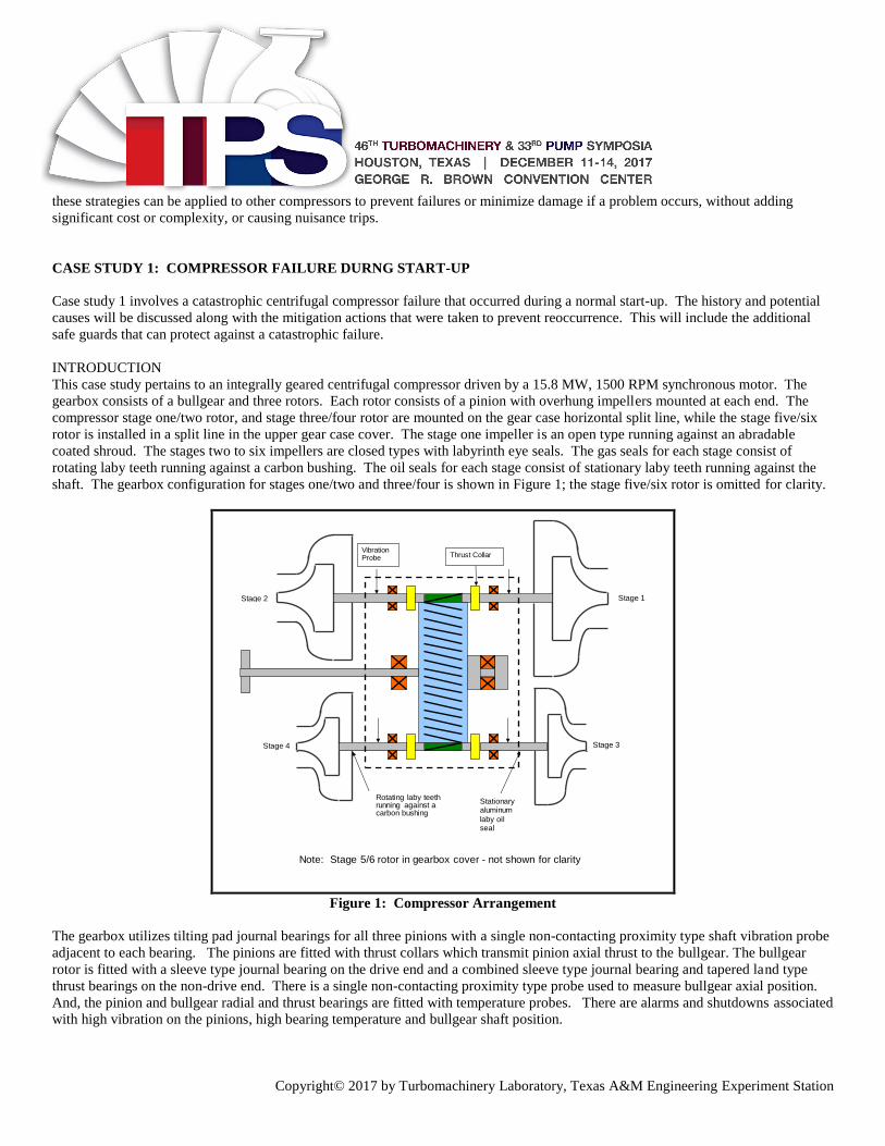
This case study pertains to an integrally geared centrifugal compressor driven by a 15.8 MW, 1500 RPM synchronous motor. The
gearbox consists of a bullgear and three rotors. Each rotor consists of a pinion with overhung impellers mounted at each end. The
compressor stage one/two rotor, and stage three/four rotor are mounted on the gear case horizontal split line, while the stage five/six
rotor is installed in a split line in the upper gear case cover. The stage one impeller is an open type running against an abradable
coated shroud. The stages two to six impellers are closed types with labyrinth eye seals. The gas seals for each stage consist of
rotating laby teeth running against a carbon bushing. The oil seals for each stage consist of stationary laby teeth running against the
shaft. The gearbox configuration for stages one/two and three/four is shown in Figure 1; the stage five/six rotor is omitted for clarity.
Note: Stage 5/6 rotor in gearbox cover - not shown for clarity
Vibration Probe
Stage 2 Stage 1
Stage 4 Stage 3
Thrust Collar
Rotating laby teeth running against a carbon bushing
Stationary aluminum
laby oil seal
Figure 1: Compressor Arrangement
The gearbox utilizes tilting pad journal bearings for all three pinions with a single non-contacting proximity type shaft vibration probe
adjacent to each bearing. The pinions are fitted with thrust collars which transmit pinion axial thrust to the bullgear. The bullgear
rotor is fitted with a sleeve type journal bearing on the drive end and a combined sleeve type journal bearing and tapered land type
thrust bearings on the non-drive end. There is a single non-contacting proximity type probe used to measure bullgear axial position.
And, the pinion and bullgear radial and thrust bearings are fitted with temperature probes. There are alarms and shutdowns associated
with high vibration on the pinions, high bearing temperature and bullgear shaft position.

Copyright© 2017 by Turbomachinery Laboratory, Texas A&M Engineering Experiment Station
FAILURE
The compressor is in clean, dry booster air service and was installed in an unheated enclosure in a northern climate. During
commissioning, the compressor was started 12 times and had run for a total of approximately 68 hours without any problems. After
the commissioning activities were completed, the compressor and all its auxiliary systems were shut down for three days waiting for
plant production to begin. The weather during this time was fairly cool. As soon as the compressor was started unusual noises were
heard from inside the enclosure. The compressor ran for approximately 17 seconds before it tripped. A motor protection relay tripped
the motor due to prolonged high current. Analysis of the voltage and current sine waves suggested that the motor reached about 90
percent of full speed at the point of trip.
The damage to the compressor was extensive. The pinion shafts were all snapped off behind the impellers due to hard rubs, apart
from the stage two impeller which had not rubbed. One of the damaged impellers is shown in Figure 2.
The stage one/two tilting pad pinion bearings are a higher rated design than the other pinion bearings and showed little to no damage.
The stage three/four and stage five/six pinion bearings were heavily damaged. An example of the damage is shown in Figure 3.
These bearings consist of five pads. The pads are made from steel with a thin Babbitt layer on the inside diameter. It can be seen that
the Babbitt was displaced due to very high loads and not wiped due to high temperatures.
Figure 2: Damage Impeller Figure 3: Damaged Pinion Bearing
Apart from stage two, the gas seal bushings and corresponding laby teeth were heavily damaged due to hard rubs. And, the laby oil
seals were also badly damaged due to hard rubs.
The thrust collars of the pinions showed significant wear, as did the mating thrust faces on the bullgear. There was significant
metallic debris in the bottom of the gearbox. However, there was no significant damage to motor, coupling, coolers, piping or oil
system. The damage was confined to the gearbox.
INVESTIGATION
Figure 4 shows the vibration trends during the start-up prior to the failure. Figure 5 shows the vibration trends during the start-up
when the failure occurred. Comparing the trends, the vibration levels for the start-up when the failure occurred were higher from the
moment the compressor was started. And, about five seconds into the start, the vibration levels for stages one and two increased
exponentially to 250 microns p-p, which is the full range of the transmitters. The vibration levels for stages three and four also
increased exponentially to 250 microns p-p, but lagged behind the stage one and two vibration increase by approximately two seconds.
The vibration levels for stages five and six showed the same trend, but lagged two seconds behind the stage three and four increase.
Note that some of the vibration readings drop sharply before the machine trip. This is because these vibration signals went to bad
quality. The compressor did not trip on high vibration because the vibration shutdowns were bypassed for 30 seconds during start-up.

Copyright© 2017 by Turbomachinery Laboratory, Texas A&M Engineering Experiment Station
Figure 4: Normal Start-Up Vibration Trends
Figure 5: Start-Up Vibration Trends During Failure
Based on prior starts, the compressor reaches full speed in about 17 to 18 seconds. As shown in Figure 4, on the start-up prior to the
failure, the vibration of all the stages spikes just before reaching full speed. It was determined that this was due to excitation from the
train torsional natural frequency (TNF). The calculated TNF is 1250 CPM, which is 83% of the operating speed of 1500 RPM. A

Copyright© 2017 by Turbomachinery Laboratory, Texas A&M Engineering Experiment Station
field test performed later confirmed the TNF. It was determined that the radial vibration response when the compressor accelerates
through the torsional critical speed was normal and not a problem
.
A review of the process trends during the start-up when the failure occurred did not show anything unusual at first. The machine
discharge pressure rose continuously for about 15 seconds, but then suddenly dropped off. The stage inlet temperature trends also
appeared consistent with past start-up trends for about 14 seconds, but then the inlet temperatures of stages three, four, five and six
rose faster, particularly stage three.
The auxiliary oil pump was started about six minutes prior to starting the compressor. Within this time the minimum oil temperature
permissive was satisfied, but the bearing temperatures had not stabilized. The bullgear bearings in particular were still very cold.
DISCUSSION
Many high speed turbomachines operate above their first critical speed and thus, pass through one or more resonant frequencies during
start-up. This can result in momentary vibration spikes, which is a normal condition. The magnitude of the vibration spike can
depend on many factors such as the amount of rotor unbalance, how much damping is present, and other factors. The vibration level
will decay as the rotor speed accelerates past the resonant frequency.
As shown in Figure 4, the vibration levels for some stages on this machine spike momentarily during the start-up as the particular
rotor accelerates through a resonant frequency. And, as noted above, the vibration on all stages spikes when the compressor
accelerates through the train torsional natural frequency. The high vibration trip set points are set at values that are lower than some of
these vibration spikes because the high vibration trip set points are based on operation at the normal operating speed. To prevent the
machine from tripping during start-up, the control system was configured to automatically bypass the high vibration trips for 30
seconds. Although this is a common method to manage vibration spikes during start-up, it also eliminates the vibration protection for
this period of time.
To prevent unnecessary high vibration alarms and trips on start-up and still provide high vibration protection, another option is to
temporarily elevate the high vibration alarm and trip set points. This method is recommended by API and is described in API-670,
“Machinery Protection Systems.” The elevated vibration alarm and trip set points need to be set higher than the rotor’s characteristic
response at any resonances during the start-up, but the levels should be set as low as possible in order to maximize the machinery
protection. In some machines, the alarm and trip points do not need to elevated at all. In other machines, the alarm and trip set points
may need to be elevated by as much as two or even three times the normal set points. However, if the set points need to be elevated
more than this, there may be a problem and this requires further review.
There are other details that need to considered as well. These include time delays, how to handle bad quality and dual instruments. In
many cases vibration alarm/trip logic is configured with a time delay to prevent spurious trips. While this may be advantageous to
prevent unnecessary spurious trips during steady state operation, it is less of an advantage during a start-up. As discussed above,
about five seconds into the start, the vibration levels for stages one and two increased exponentially to 250 microns p-p. Looking
closely at Figure 5, the exponential increase in vibration on stages one and two from low vibration to the full range of the transmitters
took three seconds. Tripping the machine sooner would limit the damage and possibly prevent a catastrophic failure. But, if there is a
time delay on a vibration trip, the machine will run longer. That is not to say that a time delay couldn’t be configured for steady state
operation. But, having no time delay on a start-up could lessen the impact of a mechanical fault.
In many cases, loss of signal or bad quality from an instrument may be configured as an alarm because it is assumed that it is an
instrument issue. However, in the case of vibration, the event can happen so quickly that the vibration probe can be wiped out before
a high vibration condition is detected by the control system. Configuring the control system with bad quality as a vote to trip protects
against this. However, it can result in unnecessary machine trips during steady state operation due to instrument issues. Configuring
bad quality as a vote to trip only during start-up is one possible solution.
Relying on a single instrument for protection also impacts the reliability. Having two instruments can improve reliability, such as the
use of “x” and “y” vibration probes adjacent to each bearing rather than just a single probe. A high vibration vote to trip from both
probes can prevent nuisance trips during steady state operation and while this can prevent unnecessary trips due to faulty instruments,

Copyright© 2017 by Turbomachinery Laboratory, Texas A&M Engineering Experiment Station
it is not as advantageous during start-up. In gearbox rotor bearing systems, vibration levels can be higher in one plane than in another
plane. Thus, if there is a fault, the vibration in one plane can react faster in one plane verses the other. Having dual probes with
nonvoting trip logic during start-up could result in tripping the machine sooner if there is a mechanical fault and again, limiting the
damage.
There are many different types of control systems and in some cases, the functionality of temporarily manipulating alarm and trip set
points at start-up may be difficult to set-up. This may result in a higher cost system, more complex controls programming and may
increase the potential for unnecessary trips during start-up. However, as discussed above, having this functionality can lower the
damage that is done if there is a problem during start-up. Each case needs to be evaluated on its own merits.
For this compressor, several potential causes for the failure were reviewed. Although there is no direct evidence, it was surmised that
the short time the auxiliary oil pump was run prior to start-up was a major contributing factor to the failure. Compared to the previous
start-up, the bearing temperature readings had not stabilized, leading to the conclusion that the rotating and stationary parts had not
reached thermal equilibrium. The differential temperatures in the rotors, bearings and casing could have been significant enough to
cause distortion and lead to hard rubs in the seal areas or impeller running fits which could have caused the failure. This was
addressed by incorporating a mandatory longer run time for the auxiliary oil pump before starting the compressor.
CONCLUSIONS – CASE STUDY 1
What can be learned from this case study is that things can go wrong during the start-up of a centrifugal compressor. Although there
are many possible root causes of catastrophic compressor failures during start-up, tripping the machine at the onset of a high vibration
excursion can minimize the damage and prevent a catastrophic failure. What is key is detecting the issue quickly and immediately
tripping the machine. As discussed above, the vibration trip set points may need to be elevated for start-up. However, the set points
should be reviewed during commissioning. This includes both the magnitude of the elevated vibration trip set point and the duration.
The trip set point should not be set so far above what is necessary that the protection is compromised and the elevated trip set points
should only be active for the time it takes the machine to get up to full speed. It should be noted that sometimes the elevated vibration
levels during start-up are high enough that vibration systems with higher ranges are required. And as discussed above, additional
items that are helpful include x” and “y” radial vibration probes adjacent to each bearing, and control logic that includes bad quality as
a vote to trip and nonvoting vibration trip logic.
This machinery protection strategy can easily be implemented on new installations provided all the requirements are understood at the
time the compressor is ordered. The strategy can also be retrofitted on existing installations, but to get the full benefit, some
additional instruments may be needed. In either case, it is key that the instrumentation is suitable for the start-up case, the control
logic is properly designed and tested before the compressor is started, and the data is reviewed after the first start-up so that the control
logic and set points are adjusted as necessary.
CASE STUDY 2: COMPRESSOR FAILURE DURNG SHUT DOWN
Case study 2 involves a centrifugal compressor that failed during a shutdown. The history and potential causes will be discussed
along with the mitigation actions that were used to prevent reoccurrence. This will include the additional safe guards that can protect
against a catastrophic failure.
INTRODUCTION
This case study pertains to an integrally geared centrifugal compressor driven by a 5000 HP, 3565 RPM induction motor. The
gearbox consists of a bullgear and three rotors. Each rotor consists of a pinion with overhung open impellers mounted at each end.
The compressor stage one/two rotor and stage three/four rotor are mounted on the gear case horizontal split line, while the stage
five/six rotor is installed in a split line in the upper gear case cover. The gas seals at each stage consist of rotating laby teeth running
against a Babbitt lined bushing. The oil seals at each stage consist of stationary laby teeth running against the shaft. The gearbox
configuration for stages one/two and stages three/four is shown in Figure 6; the stage five/six rotor is omitted for clarity.

Copyright© 2017 by Turbomachinery Laboratory, Texas A&M Engineering Experiment Station
Figure 6: Compressor Arrangement
The gearbox utilizes tilting pad journal bearings for all three pinions with a single non-contacting proximity type shaft vibration probe
adjacent to each bearing. The pinions are fitted with thrust collars which transmit pinion axial thrust to the bullgear. The thrust
bearings are on the bullgear rotor as shown in Figure 6. The bullgear journal bearings are a cylindrical sleeve type and the thrust
bearings are a tapered land type. The compressor protection system includes high pinion vibration alarms and high high pinion
vibration shutdowns.
Although this compressor is packaged with the intercoolers on a common base, several coolers were removed after it was assembled at
the compressor manufacturer for shipping purposes. The compressor was re-assembled in the field. The first, second, and third stage
intercoolers are fixed in position and Victaulic pipe couplings are used for the interstage piping connections. The fourth and fifth
stage intercoolers are mounted on spring supports and the interstage piping is hard piped with flanged connections.
HISTORY
After the compressor was commissioned, it was put into continuous service and ran for two years. During this period the compressor
was shut down approximately 12 times for short plant outages. There were no mechanical problems with the compressor during this
period. On the last shutdown, the operator was following the normal procedure to unload the compressor prior to stopping the
machine. However, as the compressor was being unloaded, the discharge pressure began to rise and the distance to surge decreased to
the point that the surge control system opened the recycle valve. Seconds later the machine tripped on high vibration and the
compressor was heavily damaged.
A careful review of the operating data revealed that the moment the recycle valve opened, the vibration on all six stages went into
alarm. It appeared that the fifth and sixth stage vibration increased faster than the other stages, followed quickly by stages two, three
and four. The data did not show any evidence of a performance instability leading up to the failure.
The compressor was disassembled and there was significant damage to rotating and stationary parts. A summary of the damage
included:
• Pinion 1 (Compressor stages one and two)

Copyright© 2017 by Turbomachinery Laboratory, Texas A&M Engineering Experiment Station
Extensive gearing damage
Moderate impeller, bearing and seal damage
• Pinion 2 (Compressor stages three and four)
Extensive gearing damage
Extensive impeller, bearing and seal damage
• Pinion 3 (Compressor stages five and six)
Extensive gearing damage
Extensive impeller, bearing and seal damage
• Bullgear
Extensive gearing damage
Bullgear bearings – Excessive thrust face Babbitt wear on the non-drive end bearing
Figure 7 shows a damaged pinion where it can be seen that the shaft end that drives the impeller was snapped off. Figure 8 shows
damage to the normally unloaded bullgear thrust bearing. This will be discussed in more detail below.
Figure 7: Damaged Pinion Figure 8: Normally Unloaded Bullgear Thrust Bearing
ROOT CAUSE ANALYSIS (RCA)
The following causes were investigated as part of the failure analysis:
• Mechanical design
• Progressive wear/damage
• Surge
• Operator error
• Control system
• Gearbox distortion
• Reverse rotation
Mechanical Design
The gear and bearing loads at the design conditions and over the full operating range were reviewed and were well within industry
experience. Thus, it was concluded that excessive gear, bearing, thrust collar or shaft loads did not contribute to the failure. During
the repair no changes were made to the compressor mechanical design.
Progressive Wear/Damage
Long term operating trends showed no signs of progressive mechanical damage or wear. There were no detectable changes in long

Copyright© 2017 by Turbomachinery Laboratory, Texas A&M Engineering Experiment Station
term vibration trends or thermodynamic performance. However, the bullgear thrust bearing damage was predominately on the non-
drive end, which is opposite the calculated direction of thrust at the design operating conditions. Thus, it is likely this damage
occurred during a transient event, such as a compressor shutdown, and not during normal steady state operation. Since there were
limited shutdowns, this damage could have gone undetected. In this scenario, progressive damage could have occurred during each
shutdown until there was sufficient wear/damage to allow for contact between rotating and stationary parts. The bullgear shaft is not
fitted with an axial position probe and so it is not possible to determine exactly when the damage occurred.
Surge
The operating data immediately prior to the failure showed no evidence of operation in surge. The machine vibration levels were
stable and the performance was not erratic up to moment of failure. Thus, it was concluded that that surge did not contribute to the
failure.
Operator Error
There was no evidence of mis-operation. The compressor was not operated in surge or at an overload condition. And although the
recycle valve opened just prior to the trip, the control system performed as designed to prevent a surge. This machine had been
through several full load trips previously in which the recycle valve opened automatically. There were no known mechanical issues
following these incidents.
Control System
There was no evidence that the compressor controls did not perform as designed. The mechanical protection system was consistent
with many other similar machines in industry in this type of service. In addition, the compressor was shut down numerous times
without any issues.
Gearbox Distortion
The millwrights that removed the compressor after the failure reported a difficult time removing some of the piping due to excessive
misalignment. During reassembly at site after the repair, numerous interstage pipes had to be modified in order to correct this piping
misalignment. A picture showing some of the gross piping misalignment is shown in Figure 9. It was concluded that gearbox
distortion resulting from excessive piping misalignment could have contributed to the failure by resulting in reduced impeller to
shroud running clearances and/or bearing and seal misalignment.
Figure 9: Piping Misalignment

Copyright© 2017 by Turbomachinery Laboratory, Texas A&M Engineering Experiment Station
Reverse Rotation
A review of the data at the time of the failure did not show any evidence of reverse rotation on the compressor shutdown. After the
repair, the compressor went through extensive testing at site. Following the first full load shutdown test it was observed that the
compressor stopped rotating about 10 seconds after being tripped and then spun backwards for about one and a half minutes, reaching
a reverse speed of about 1000 RPM. This was seen by a GE-BN vibration analyzer that was being used for detailed vibration testing
following the repair. See Figure 10. Operating in reverse is something that should be prevented because of potential for damage/wear
due to lubrication problems, possible over pressure of oil pump suction piping, damage to oil pump foot valves and possible damage
to bearings. The bullgear tapered land thrust bearings in this machine are a unidirectional design and have significantly reduced load
carrying capability when operating in the reverse direction. If the normally unloaded bullgear thrust bearing was damaged due to
repeated reverse rotation incidents, this could have contributed to the compressor failure.
Figure 10: Speed and Verses Time Shutdown Trend
On a compressor shutdown, the recycle valve opens to reduce the discharge pressure to prevent surge and reverse rotation. If the
discharge pressure is not reduced quickly enough, the trapped gas can act like a brake, stopping the compressor and then reverse
flowing until the suction and discharge pressures equalize. High reverse flow through the compressor can cause the compressor to
rotate in reverse and act like an expander. To prevent this from occurring, the recycle valve needs to be sized to handle the required
flow, the recycle valve needs to open quickly, a check valve needs to be installed downstream of the compressor discharge and the
discharge piping volume needs to be minimized. To address this for this compressor, the recycle valve opening time was reduced as
much as possible and a discharge dump valve was added. The dump valve opens on a compressor shutdown to vent high pressure
discharge gas to atmosphere. There are no permit implications from venting in this particular application.
RCA CONCLUSION
It was concluded that the compressor failure was most likely a result of a sudden hard seal and/or impeller rub in the fifth stage
followed by catastrophic secondary damage to stages one, two, three, four and six. All or some of the following issues most likely
caused and/or contributed to the failure:
• Reduced operating clearances due to excessive gearbox distortion caused by excessive pipe strain
• Non-drive end bullgear thrust bearing wear/damage during repeated shutdown reverse rotation incidents
• Non-drive end bullgear thrust bearing wear due to gearbox distortion
CORRECTIVE ACTION
The following correction actions were implemented:
• Ensured there was minimal gearbox distortion due to excessive piping misalignment. During re-assembly several pipes had

Copyright© 2017 by Turbomachinery Laboratory, Texas A&M Engineering Experiment Station
to be modified to accomplish this.
• Added a discharge dump valve that opens on a compressor shutdown to vent high pressure discharge gas to atmosphere. In
addition, the recycle valve opening time on a machine trip was reduced as much as possible
• Added a bullgear axial position probe for indication, alarm and shutdown protection.
The compressor has operated well since it was repaired and the corrective actions were implemented. There have been no indications
of any mechanical damage. The vibrations have remained low, the bullgear axial position has been stable, the seal leakage has been
acceptable and there has been no change in the thermodynamic performance of the compressor.
CONCLUSIONS – CASE STUDY 2
What can be learned from this case study is that things can go wrong during the shutdown of a centrifugal compressor. In many cases,
there are undetected problems that don’t show up until the compressor is shut down. As this case study shows, it is likely that either
the normally inactive bullgear bearing was worn and/or the internal compressors clearances were tighter than design due to excessive
gearbox distortion.
In this compressor design, the bullgear position affects the axial position of all the rotors. In this type of compressor, the bullgear
thrust bearing mean sliding velocity and unit loading tend to be low and as such the thrust bearings rarely fail. However, a couple of
issues were uncovered in the investigation which may have led to undetected wear or damage. And, if there was thrust bearing wear,
the axial impeller, bearing and seal clearances on all the rotors could have been adversely impacted. This could have been detected if
the bullgear axial position was monitored and if the control system included the appropriate protections. Since the suspected wear is
on the normally inactive thrust bearing (not loaded during steady stage operation at design conditions) and is only loaded during
transient operating conditions like start-up and shut down, it is also important that the protections include the normally inactive thrust
bearing too. It would also be very useful if the condition monitoring system included the capability to compare axial position from
shutdown to shutdown to identify changes that might indicate wear or damage.
As discussed above, it is also very plausible that the progressive bullgear thrust bearing wear was a result of repeated reverse rotation
incidents that occurred when the machine was shut down. This could have been caught during commissioning and is a good learning
experience. It really shows how important it is to have experienced, qualified people lead critical compressor commissioning
activities and that they look at all aspects of the machine operation.
The degree of piping misalignment in this compressor system was excessive and was probably an issue even during the initial
installation. Just like commissioning, it is critical to have experienced, qualified people lead the installation. When problems arise,
like piping misalignment, it is important that these get escalated and resolved properly. In this case, the fixes to the misalignment
made during construction did not alleviate long term distortion.
In summary, what can be concluded for this example is that sufficient instrumentation, controls, machinery protections and condition
monitoring is needed to help avoid catastrophic compressor failures. In addition, it is key to have the right people plan and lead
compressor installation and commissioning activities to ensure successful long term operation.
CASE STUDY 3: COMPRESSOR FAILURE DURNG MANUAL OPERATION
Case study 3 involves a centrifugal compressor that failed catastrophically when it was run in manual and then shutdown. The history
and potential causes will be discussed along with the mitigation actions that were used to prevent reoccurrence. This will include the
additional safe guards that can protect against a catastrophic failure.
INTRODUCTION
This case study pertains to an integrally geared centrifugal compressor driven by a 2500 HP, 3585 RPM induction motor. The
gearbox consists of a bullgear and three rotors. Each rotor consists of a pinion with a single overhung open impeller mounted at one
end. The compressor stage one and two rotors are mounted on the gear case horizontal split line, while the stage three rotor is
installed in a split line in the upper gear case cover. The gas seals at each stage consist of a single dry gas seal (DGS). The gearbox
configuration is shown in Figure 11.

Copyright© 2017 by Turbomachinery Laboratory, Texas A&M Engineering Experiment Station
Figure 11: Compressor Configuration
The gearbox utilizes tilting pad journal bearings for all three pinions with a single non-contacting proximity type shaft vibration probe
adjacent to each impeller side bearing. The pinion rotors are fitted with thrust bearings. The normally active thrust bearings are a
tapered land type and the normally inactive thrust bearings are a tilting pad type. The gearbox also utilizes axial position probes at the
end of each pinion to monitor the thrust bearing condition. The bullgear journal bearings are a cylindrical sleeve type and the bullgear
thrust bearings are a flat land type. The compressor protection system includes high pinion vibration alarms and trips, and high and
low pinion axial position alarms and trips.
This compressor is used in a closed loop, mixed refrigerant (MR) system, which provides refrigeration for an industrial gas plant. A
simplified P&ID is shown in Figure 12. In this cycle, MR is compressed in the compressor, condensed in the main heat exchanger,
expanded across an expansion valve, and evaporated in another section of the main heat exchanger. As shown in the P&ID there are
also some small vent valves. These are used to control the composition of the MR and vent gas if the system pressures become
excessive.

Copyright© 2017 by Turbomachinery Laboratory, Texas A&M Engineering Experiment Station
Figure 12: P&ID
HISTORY
The compressor was in continuous service in an industrial gas plant. After about three years of operation there was a second stage
thrust bearing failure that occurred during a re-start after a power outage. After re-starting, the compressor control valves were
operated in manual and the operator was having difficulty controlling the process. The damage was attributed to operation in a heavy
stonewall condition. Some additional protections were added to warn the operators if the compressor was operated in this condition in
the future.
The compressor ran well for the next five years until there was an upset condition in the industrial gas plant which resulted in a loss of
the heat load. The MR system was kept in operation to avoid a shutdown and restart. However, the loss of the heat load caused
changes in the MR system operating conditions. Initially there was a significant drop in the system pressures and temperatures as
more MR was condensed in the heat exchanger due to the loss of the heat load. With the control valves being operated in manual, the
expansion valve was further opened. This brought back the compressor suction pressure and system temperatures, but the discharge
pressure was still lower than design. This resulted in the compressor operating near the stonewall condition, which was a concern
based on the previous failure. The expansion valve was then pinched back while the compressor recycle valve was slowly opened in
an attempt to increase the pressure ratio while maintaining reasonable system pressures and temperatures. But, these changes caused
the compressor suction pressure to slowly rise and stabilize at a higher pressure than design, while the discharge pressure and system
temperatures slowly dropped. Once the recycle valve was completely open, the compressor suction pressure and machine power
increased very rapidly. In a little over a minute the suction pressure went from 115 percent of design to 160 percent of design. The
suction valve was then closed, but this didn’t lower the suction pressure or machine power and the operator tripped the machine. After
the shutdown, the suction pressure momentarily spiked to over 300 percent of design before the system settled out at about 150
percent of design suction pressure. Trends of suction and discharge pressure for the last ten minutes of operation are shown in Figure
13. After the machine was shut down, there were significant changes in the stage one and two rotor axial positions, which indicated
possible thrust bearing damage. See Figure 14.

Copyright© 2017 by Turbomachinery Laboratory, Texas A&M Engineering Experiment Station
Figure 13: Pressure Trends
Figure 14: Axial Position Trends
The compressor was disassembled and there was significant damage to several thrust bearings. A brief assessment of the as found
machine condition is described below.
• Rotor 1 (Compressor stage one)
No gear tooth, active thrust bearing or dry gas seal damage
Light axial impeller rubs at OD
Some varnish on radial bearing pads
Heavy inactive thrust bearing damage
• Rotor 2 (Compressor stage two)
No impeller, gear tooth, radial bearing, or active thrust bearing damage
Rub on DGS hard faces, but seal faces intact
Heavy inactive thrust bearing damage
• Rotor 3 (Compressor stage three)

Copyright© 2017 by Turbomachinery Laboratory, Texas A&M Engineering Experiment Station
No gear tooth, radial bearing, active thrust bearing, inactive thrust bearing or dry gas seal damage
Light axial impeller rubs at OD
• Bullgear
No gear tooth, radial bearing or inactive thrust bearing damage
Heavy active thrust bearing damage
Figure 15 shows a picture of the damaged first stage inactive thrust bearing.
Figure 15: Pinion 2 Inactive Thrust Bearing Damage
ROOT CAUSE ANALYSIS (RCA)
The following causes were investigated as part of the failure analysis:
• Mechanical design
• Progressive wear/damage
• Surge
• Lack of lubrication
• Thrust overload before shutdown
• Thrust overload after shutdown
Mechanical Design
The gear and bearing loads at the design conditions were reviewed and were well within industry experience. Thus, it was concluded
that excessive mechanical loads at design conditions was not an issue. During the repair no changes were made to the compressor
mechanical design.
Progressive Wear/Damage
Long term operating trends showed no signs of progressive mechanical damage or wear. There were no detectable changes in long
term vibration trends, rotor axial position trends or thermodynamic performance. This also included a review of the shutdown trends.
When this machine is shutdown, the rotors shift to the normally inactive thrust bearing position. Previous shutdown trends did not
show any differences in the axial position movement, indicating that there was no progressive inactive thrust bearing damage.
Surge
The operating data prior to the failure showed no evidence of operation in surge. The machine vibration levels and rotor axial position
trends were stable. And although the operating conditions were changing, there were no rapid oscillations in pressures or power that
would have been an indication of surge. Thus, it was concluded that surge prior to the shutdown did not contribute to the failure.

Copyright© 2017 by Turbomachinery Laboratory, Texas A&M Engineering Experiment Station
Lack of Lubrication
Immediately after the compressor was shutdown, the oil pressure momentarily dipped from 27 psig to 14 psig, before increasing back
to 27 psig. The lubrication system includes a main oil pump (MOP) driven off the bullgear shaft, and an electric motor driven
auxiliary oil pump (AOP). On a compressor shutdown, the AOP is started because the capacity of the MOP will fall off as the
compressor decelerates. The low oil pressure shutdown set point is 15 psig. A dip in oil pressure may be due to a delay in the start of
the AOP and/or an indication of rapid deceleration of the compressor. This momentary drop of oil supply could have contributed to
the bearing damage.
Thrust Overload Before Shutdown
After the initial drop in suction pressure, the suction pressure rose during the entire event. Using shop test data, a thermodynamic
performance model was created to evaluate the overall operating conditions and interstage conditions leading up to the failure. As
shown in Figure 16, the compressor was driven into a stonewall condition as the suction pressure rose. The interstage performance at
different conditions had to be extrapolated from the shop test stage curves.
Figure 16: Compressor Performance During Event
At the operating points shown on the performance curves, the calculated interstage conditions were used to estimate the thrust forces.
Thrust forces are a combination of the differential pressure forces acting on both sides of the impeller and the gear reaction forces.
Figure 17 shows a simplified model of the pressure forces acting on the impeller. The pressure forces drive the rotors towards the
impeller end at normal operating conditions. For rotors one and two, the gear reaction forces are opposite in direction to the impeller
pressure forces. However, at the design point, the gear reaction forces are less than 50 percent of the pressure forces acting on the
impeller, and so the net force is still towards the impeller. Note that for rotor three, the pressure force and gear reaction force are in
the same direction at normal operating conditions. At the higher suction pressure conditions, there is a modest increase in the
calculated net rotor one axial thrust force while the corresponding calculated axial thrust forces for rotors two and three drops. The
rotor one thrust force is still well within design limits. And, as shown in Figure 14, the shift in axial position on all the rotors
coincided with machine shutdown. So, it is unlikely that the first and second stage inactive thrust bearing damage occurred before the
shutdown.
During normal operation the bullgear is thrusted towards the non-drive end (NDE). The bullgear thrust forces are purely a function of
the net gear reaction forces from all three rotors. At the higher load conditions prior to the shutdown, the calculated bull gear active
thrust bearing load was very close to the design limit. Marginal lube oil flow, some minor misalignment, and other factors combined
with the high loading at the time of the shutdown may have led to the active thrust bearing damage.

Copyright© 2017 by Turbomachinery Laboratory, Texas A&M Engineering Experiment Station
Figure 17: Pressure Forces Acting On Impeller
Thrust Overload After Shutdown
As the pressures in the compressor settle out, the pressure forces acting on the impellers will drive the rotors in the normally inactive
direction, away from the impeller. As shown in figure 17, the face area on the front side of the impeller is larger than the back side
due to the area taken up by the shaft. So, at settle out, the thrust force created by the pressure forces acting on the impeller is equal to
the pressure times the cross sectional area of the shaft behind the impeller. At higher pressures, the impeller pressure forces in the
inactive direction are higher and could be much higher than the forces at design operating conditions in the active direction. The gear
reaction forces will also drop very quickly with speed.
When the compressor was shutdown, the suction pressure was already much higher than design and the resulting settle out pressure
would be much higher than if the machine was shut down at the normal pressure conditions. There is not a lot piping volume between
the suction valve and the compressor inlet. Shutting the suction valve prior to shutting down the compressor could have caused a
higher settle out pressure than had the valve been kept open and could also have contributed to a higher spike in suction pressure. The
large spike in suction pressure immediately after the shutdown could be a sign of a large reverse flow through the compressor as the
machine coasted down in speed, creating even higher pressure forces.
Although there is no data available to calculate the actual forces as the machine is coasting down, it seems plausible that the high
suction pressure condition at the time of the shutdown and/or a large reverse flow through the compressor could have caused high
thrust load conditions. The other thing to consider is that bearing load capacity is a function of speed. At slower speeds, the bearing
load capacity is lower. And the speed will drop off quickly as the machine is coasting down after a shutdown.
The other possibility is that a high reverse flow through the compressor could cause the machine to stop quickly and then rotate in the
reverse direction. There is no data to substantiate this, but the rotor one inactive thrust bearing damage seemed to be consistent with
reverse rotation based on the pattern of the Babbitt smearing. Although the damage evidence isn’t conclusive, it suggests the
possibility. This is significant because the pinion thrust bearings are a unidirectional design. Allowable bearing load in the reverse
direction of rotation is substantially less and is even lower at lower speeds.
Reverse rotation could also cause or contribute to active (NDE) bullgear thrust bearing damage. If the compressor stops and reverses
rotation, the thrust forces would change direction and the bullgear would thrust towards the NDE. It is possible that there could be
enough load at low speeds to cause thrust bearing damage while rotating in the reverse direction, especially if there was any possibility
of marginal oil supply, discussed previously. Flat land thrust bearings are not very forgiving.
RCA CONCLUSION
There are many assumptions that were evaluated as part of the RCA and there is a fair amount of uncertainty as to the exact cause.
However, it seems likely that the high suction pressure condition and spike in suction pressure after the shutdown caused or

Copyright© 2017 by Turbomachinery Laboratory, Texas A&M Engineering Experiment Station
contributed to the failure. This compressor is in a closed loop refrigeration system which involves condensing and evaporation. This
is very different from a machine in an open loop, once through system and how the compressor operating conditions are affected by
process and control valve changes are not as intuitive. The events leading up the high suction pressure condition prior to the shutdown
occurred because the system didn’t respond as expected to the valve position changes. As discussed above, the high suction pressure
condition led to a high power condition and high thrust forces in the normally inactive direction on a compressor shutdown. The
corrective actions need to protect against high suction pressure, protect against high power, and incorporate hardware and controls to
prevent a spike in suction pressure on a compressor trip.
CORRECTIVE ACTION
The compressor control system consists of a number of interlocks, alarms and trips to ensure safe, reliable operation of the machine.
The following changes were made to the control system to address the issues discussed in the RCA:
1. Addition of a high suction pressure trip.
2. Addition of an interlock to prevent opening of the suction valve if the pressure difference across the valve is too high. This will
prevent accidental supercharging of the compressor suction.
3. Addition of a small bypass valve around the suction valve to allow for a controlled equalization of pressure across the suction
valve before opening the suction valve.
4. Addition of a discharge dump valve that quickly opens on a machine shutdown and prevents high backflow through the
compressor and prevents a significant spike in suction pressure.
5. Lowering of the high motor amp trip set point to prevent overloading of the compressor.
6. Ensuring there is no delay in starting the AOP on a compressor shutdown.
CONCLUSIONS – CASE STUDY 3
What can be learned from this case study is that in many instances the compressor controls and machinery protections are designed
and tuned for steady state and normal start-up/shutdown transient conditions. However, it is important to understand all possible
transient operating conditions when designing compressor control and protection systems. In this case study the machine was run in a
condition that it wasn’t designed for and automatic controls were not utilized leading to unstable operation and the overload conditions
that caused the failure. As a result, additional safeguards are needed to prevent accidental overloading of the compressor, especially
during transient operating conditions. This includes safeguards against high suction pressure and high power conditions and
safeguards to prevent overloading when the compressor is tripped.
Although it was concluded that surge did not contribute to this failure, it is important to recognize that the surge control system needs
to prevent operation in surge over all operating conditions, especially off design conditions. In addition, a surge detection system
provides further protection in case a compressor is operating in surge either due to a fault of the surge control system, or deterioration,
such as fouling or erosion, that causes a shift in the compressor surge line. Smith (March 2012) describes an impeller failure caused by
operating in low flow stall (near surge). Fouling in the compressor caused a shift in the surge line which resulted in operation near
surge.
Also, Smith (May 2013) describes unusual thrust collar wear in an integrally geared compressor that was at least partly attributed to a
lubrication issue when the machine was shut down and not unloaded. Smith (May 2015) also describes unusual thrust collar wear in
an integrally geared compressor that was also at least partly attributed to a lubrication issue. However, in this case, it had to with part
of the machine being under pressure at the time of start-up. Although neither case led to a sudden catastrophic compressor failure, it
could have if changes were not made to address the damage. And, it reinforces the need to understand all the operating conditions,
including transient conditions, when designing compressor control and protection systems. In some cases, the operating conditions
and/or operating procedures may need to be altered to prevent machine damage. In this particular application, the system was run in a
condition it was not designed for (operation without a heat load). In hindsight, shutting down the system, rather than operating it
outside its design boundaries would have been less disruptive.
CASE STUDY 4: COMPRESSOR FAILURE DUE TO LONG TERM UNDETECTED WEAR
Case study 4 involves a centrifugal compressor that failed catastrophically on a startup due to long term progressive wear. The history
and potential causes will be discussed along with the mitigation actions that were used to prevent reoccurrence. This will include the

Copyright© 2017 by Turbomachinery Laboratory, Texas A&M Engineering Experiment Station
additional safe guards that can protect against a catastrophic failure.
INTRODUCTION
This case study pertains to a centrifugal compressor train consisting of a 1490 RPM, 4500 HP induction motor, a gearbox, a high
pressure compressor and a low pressure compressor. The motor drives the gearbox which in turn drives the high pressure and low
pressure compressors, which operate at 15186 RPM. This basic train arrangement is shown in Figure 18.
High Pressure Compressor 15,186 RPM
Gear4,5000 HP1,590 RPM
Motor
CouplingLow Pressure Compressor 15,186 RPM
Figure 18: Compressor Configuration
The high pressure compressor rotor consists of three closed impellers in-between two radial bearings on a single shaft with rotating
labyrinth gas seals and stationary labyrinth oil seals at each end. The low speed compressor rotor consists of five closed impellers in-
between two radial bearings, also with rotating labyrinth gas seals and stationary oil seals at each end. The impellers in both
compressors are fitted with rotating labyrinth eye seals and rotating back of impeller seals. The gas seals and impeller seals run
against stationary bushings that are coated with a soft metal to allow for some minor contact. The gearbox includes a helical type
bullgear and pinion. The pinion has thrust collars which transmit the combined compressor and gear axial forces to the bullgear. The
only thrust bearings in the machinery train are on the low speed bullgear rotor.
The compressor shaft end gas seals are a multi-port design consisting of a nitrogen injection chamber (atmospheric side), vent
chamber and process gas injection chamber (process side). A minimum differential pressure between the nitrogen injection pressure
and the intermediate vent port pressure is maintained to prevent process gas leakage from the end of the seal. And a minimum
differential pressure between the vent port pressure and the process injection port is maintained to prevent process contamination.
The compressor and gearbox pinion utilize tilting pad type journal bearings. The instrumentation includes a single non-contacting
proximity type shaft vibration probe adjacent to each compressor and pinion radial bearing. Each compressor and pinion radial
bearing is also fitted with a temperature probe. The gearbox thrust bearing is fitted with temperature probes and there is an axial
position probe that is used to monitor shaft position. There are alarms and shutdowns associated with high vibration, high bearing
temperature and shaft position.
HISTORY
The compressor is in clean, dry process gas service and was commissioned in the late 1990s. It was initially in continuous service, but
due to a change in the customer demand, the compressor was changed to time of day operation after a couple of years. Over the next
12 years the compressor was started and stopped almost 3000 times.
After about seven years of service there was a modest increase in the gearbox pinion bearing temperatures. Some minor damage was
discovered and these radial bearings were eventually replaced with a higher capacity, upgraded design. The compressor was never
disassembled for inspection. The compressor mechanical and thermodynamic performance was reviewed monthly and the efficiency,
rotor vibrations and bearing temperatures appeared stable.

Copyright© 2017 by Turbomachinery Laboratory, Texas A&M Engineering Experiment Station
The failure occurred on a normal machine start-up. The machine ran for 10 seconds and the control system automatically shut down
the compressor due to low seal gas differential pressure. Prior to this there were no issues maintaining the required seal gas
differential pressures.
DISCUSSION
The damage to the compressor and gearbox was extensive. The labyrinth seals and seal bushings in both compressors were badly
rubbed and had to be replaced. The bullgear and pinion teeth had also failed. See Figure 19. And the couplings between the gearbox
and high pressure compressor and between the high pressure compressor and low pressure compressor were twisted and bent. It was
clear that this was a very violent failure.
Figure 19: Gear Damage Figure 20: Bearing Damage
One of the most interesting finds was with the four compressor bearings. These are tilting pad type bearings. The pads are made from
steel with a thin Babbitt layer on the inside diameter. The bearing Babbitt surfaces were found to be in good condition, especially
considering the years in service. There were no indications of Babbitt fatigue, scoring or wiping and no signs of oil varnishing or
problems associated with oil contamination, oil oxidation or excessive heat. However, wear and contact damage was noted on the oil
retaining ring (oil dam). This was rather surprising given that the oil retaining ring clearance by design is greater than journal
clearance. From these inspections it was clear that the shaft had come into hard contact with the oil dam despite no significant wear
of the Babbitted surfaces. When the bearings were disassembled, severe wear and fretting damage was found on the back of the pads
at the pivot points and on the corresponding bearing housing bore surfaces. See Figure 20. This extreme wear and fretting damage
caused flat spots at the pivot locations which inhibited the rocking action of the pads. The wear also resulted in significant increases
in bearing clearances. For example, the as found low pressure compressor non-drive end (NDE) bearing clearance was .025 inches
verses a design maximum of .007 inches. It is unlikely that the wear occurred at the time of the failure. The damage was more
consistent with long term, progressive wear. What is real surprising is, that despite this notable bearing damage, there was no
significant increase in compressor vibrations during steady state operation.
The compressor bearings are lightly loaded and one possibility is that the pads may be more susceptible to fluttering, especially during
start-up and shut down. This could cause excessive movement which could cause wear on the pad and bearing housing pivot points.
The high number of stops and starts may have contributed to the wear. Whether the wear was due to this or other factors, it is still
surprising that, the machine vibration levels remained stable and within normal operating limits. In addition, no deviations occurred
with other related compressor monitoring parameters including bearing temperatures, shaft position or seal gas differential pressures.
It is believed that this bearing wear eventually led to very hard seal rubs which opened up the seal clearances sufficiently to cause a
low seal gas differential pressure condition. It could have also caused a high torque condition which overloaded and failed the gear

Copyright© 2017 by Turbomachinery Laboratory, Texas A&M Engineering Experiment Station
teeth. So, how could this have been detected in order to avoid all the consequential damage?
CONDITION MONITORING
Condition monitoring involves regularly assessing the machine condition, and taking action only if a potential problem is identified.
Specific data is collected and analyzed in order to achieve this goal.
The scope of a machinery condition monitoring program typically includes the following checks.
1. Scheduled visual inspection
2. Vibration monitoring and analysis
3. Lube oil analysis
4. Thermodynamic performance monitoring and analysis
For this compressor, the periodic visual inspections during normal operation did not reveal any unusual noise or vibrations, leaks,
loose or broken bolts, foundation cracks or other problems that would have indicated there was potential mechanical issue with the
compressor prior to the failure. Periodic lube oil analyses were also performed and were normal, which indicated the oil had not
degraded or was contaminated.
As mentioned previously, the compressor mechanical and thermodynamic performance was reviewed monthly and the efficiency,
rotor vibrations and bearing temperatures were stable. A plot of 18 months of vibration data leading up to the failure is shown in
Figure 21. The low pressure compressor DE vibration was somewhat high, but it appeared stable and was below the alarm point. A
more detailed review showed that this vibration had slowly gone up almost one mil in vibration since commissioning (13 years later).
And although the vibration appeared stable, it had been approaching the alarm limit. Other than this vibration point, all other
compressor and gearbox vibrations were significantly lower than the alarm set points.
Figure 21: Vibration Trends
On this machine the vibration protection is bypassed for 30 seconds during start-up. The vibration bypass allows for the rotors to
accelerate through the shaft critical speeds on start-up without shutting down on high vibration. After the failure the start-up vibration
trends from some of the recent successful start-ups were reviewed. Other than moderately higher pinion non-drive end (NDE) bearing
vibration, none of the other compressor or gearbox vibration trends were different from previous start-ups. However, start-up trends
were not saved or reviewed and only recent start-up data could be obtained. It’s not certain if the start-up vibration levels changed
significantly through the years of operation.
After the repair the steady state vibration levels and start-up vibration peaks were much lower than the values before the failure. A
couple of changes could be made to improve the probability of identifying the degraded bearing condition in the future and should be
Copyright© 2017 by Turbomachinery Laboratory, Texas A&M Engineering Experiment Station
considered for other compressors.
1. Setting the vibration alarm points closer to the operating values. In this case, the low pressure compressor DE vibration may
have gone into alarm and triggered action before the failure. Some compressor suppliers recommend vibration alarm and trip
set points based on allowable vibration levels. If the operating values are much lower, there can be a lot of margin between
the actual operating value and the alarm point. An increase in vibration is a sign of progressive wear, damage, fouling, etc.
Setting the alarm points closer to the steady state vibration values could provide earlier indication of an impending problem.
2. Rather than bypassing vibration on start-up, higher vibration trip values can be applied during start-up. These higher trip
values would only be in effect during the start-up. More information on start-up trip multipliers is described in API-670.
However, start-up vibration peak vibrations can vary a little if parameters such as oil temperature, oil pressure, or small
changes in load occur. This can create a false indication of a problem. So, this needs to be taken into consideration if
reviewing start-up trends as part of machinery condition monitoring.
PREVENTATIVE MAINTENANCE
Preventive maintenance is tasks that should be performed to ensure the safe, reliable, and cost-effective operation of equipment and
plant. Some maintenance tasks can be performed while the larger equipment system remains in its normal process operating mode.
For centrifugal compressors these tasks are normally included in the condition monitoring program. Downtime maintenance tasks can
only be performed when the larger equipment system is either taken out of its normal process operating mode, or shut down. In this
case, a major inspection may be considered at some interval. However, disassembling and reassembling a compressor costs time and
money and is not risk free. The value of an internal inspection needs to evaluated against the risk and cost of doing the work. It also
depends on the confidence that the machinery condition monitoring data is sufficient to determine the mechanical and performance
health of the machine. This could be done on a machine by machine basis rather than implementing this broadly. In the case of the
compressor that is the subject of this tutorial, an internal inspection will be considered in the future.
CONCLUSIONS – CAST STUDY 4
Similar to Case Study 1, what can be learned from this case study is that things can go wrong during the start-up of a centrifugal
compressor, and, having a machinery protection strategy that includes start-up vibration protection is key to preventing catastrophic
compressor failures. It is equally important that the control logic and alarm and trip points are set up appropriately. Setting trip points
during start-up that are too high needlessly delays a trip and allows the machine to run longer in a damaged state. Eliminating time
delays and treating vibration instrument bad quality as a vote to trip during a start-up also results in less run time with the machine in a
damaged state and minimizes the potential consequential damage. A further improvement is including “x” and “y” vibration probes so
that the vibration in both planes is monitored.
Another thing that can be learned from this case study is the importance of equipment condition monitoring. In many cases, a change
in mechanical or thermodynamic performance is not noted until something goes into alarm. A robust equipment monitoring system
should pick up small changes well in advance of an alarm point being reached, allowing time for action to be taken. Ideally, the
equipment condition monitoring is automated and does not rely on a person to review trend data. And, ideally, this should include
both steady state and start-up/shutdown trending.
Lastly, what can be learned from this is recognizing that a change in operation may necessitate a change in the machinery condition
monitoring and/or maintenance strategy. In this case, the change from continuous service to intermittent duty is a significant change
and a more proactive preventative maintenance strategy such as disassembling and inspecting the machine at some frequency should
be evaluated. The key is having a machinery condition monitoring program, machinery protection strategy and maintenance strategy
that fit the machine design and operational demands.
CONCLUSIONS
Compressor machine and system designs focus mainly on steady state operation. This makes sense since this where the machine will
run most of the time. However, transient cases often don’t get the same level of attention during either the design or operational
phase. As discussed in this tutorial, many, if not most catastrophic compressor failures occur when operating in transient operation.
These can be prevented or minimized by having a good machinery condition monitoring program, a good machinery protection

Copyright© 2017 by Turbomachinery Laboratory, Texas A&M Engineering Experiment Station
system and good maintenance practices. Some recommendations include.
1. Start-up vibration protection per API-670. This should also include no time delay on a trip signal, bad quality as a vote to
trip and the set point and duration for the trip multipliers should be minimized based on previous starts.
2. “X” and “y” vibration probes should be considered. If “”x” and “y” probes are supplied, the trip logic for start-up should be
nonvoting for start-up, meaning that if the vibration reaches the trip set point on either probe, the machine will trip.
3. Axial position monitoring and protection should include the bullgear shaft.
4. Interstage pressures and temperatures monitoring to allow for evaluation of stage performance
5. All possible transient operating conditions (start-up, shutdown and off design) need to be identified when designing
compressor control and protection systems. Additional safeguards to prevent accidental overloading of the compressor
during these transient operating conditions need to be identified and addressed.
6. A robust surge protection (avoidance) system designed to function over all process conditions. In addition, a surge detection
system should be considered.
7. Understanding that installation and commissioning of compressor systems is critical to the reliability of the machine. The
means that people with the right skills and experience need to lead these activities to ensure the machine is installed correctly,
all the instruments and controls are properly configured and tested, any adjustments in controls or set points identified during
commissioning are made, and that any deficiencies uncovered during commissioning are addressed.
8. Having a robust equipment condition monitoring system that is able to identify early stages of machine wear and damage
during steady state operation. Additional equipment condition monitoring techniques which include comparison of start-up
trends and comparison of shutdown trends should be considered.
9. Recognition that a change in operation may necessitate a change in the machinery condition monitoring and/or maintenance
strategies.
With these mitigations in place it is possible to greatly reduce the probability of catastrophic compressor failures during transient
operating conditions.
REFERENCES
API-670, “Machinery Protection Systems”, Fifth Edition, November 2014, API, Washington, DC.
API-617, “Axial and Centrifugal Compressors and Expander-Compressors for Petroleum, Chemical and Gas Industry Services”,
Seventh Edition, API, Washington, DC.
Smith, Patrick J., “Catastrophic Centrifugal Failure During Start-up”, Energy-Tech Magazine, September 2015.
Smith, Patrick J., “Catastrophic Centrifugal Compressor Failure During Shutdown”, Energy-Tech Magazine, December 2015.
Smith, Patrick J., “The Dangers of Running a Compressor in Manual”, Energy-Tech Magazine, August 2016.
Smith, Patrick J., “Destructive Forces in Centrifugal Compressors”, Energy-Tech Magazine, March 2012
Smith, Patrick J., “Undetected Bearing Wear Leads to Catastrophic Compressor Failure”, Energy-Tech Magazine, December 2013.
Smith, Patrick J., “Steam Turbine Driven Integrally Geared Compressor Gearing Failures”, Energy-Tech Magazine, May 2013
Smith, Patrick J., “Thrust collar wear in an integrally geared Turbocompressor”, Energy-Tech Magazine, May 2015
ACKNOWLEDGEMENTS
The author would like to thank Elizabeth Schaub for her encouragement and support in putting together this tutorial.

Copyright© 2017 by Turbomachinery Laboratory, Texas A&M Engineering Experiment Station