
STRAND LIGHTING - Theatrecrafts · It is smoothed by a choke input circuit, giving a good I...
20
STRAND LIGHTING STRANDELECTRONip _ _ CONTROL B.B.C. RIVERSIDE STUDIO NO.2 Technical Description. Publi,;heJ by THe STftAND ELECTRIC & ENGINEERING CO.,. LTD, Hr11d 0/lk• and Showrooms 29 KING STREET COVENT GARDEN LONDON W.C.2 L.W .L./MAY,58.
Transcript of STRAND LIGHTING - Theatrecrafts · It is smoothed by a choke input circuit, giving a good I...

STRAND LIGHTING
STRAND ELECTRONip __ CONTROL
B.B.C. RIVERSIDE STUDIO NO.2
Technical Description.
Publi,;heJ by
THe STftAND ELECTRIC & ENGINEERING CO.,. LTD, Hr11d 0/lk• and Showrooms 29 KING STREET COVENT GARDEN LONDON W.C.2
L.W.L./MAY,58.

D
STRAND ELECTRONIC CONTROL.
B.B.C. RIVERSIDE STU])I9 NOo_11.
Technical Dat.
1) General.
2) Switching on.
3) Theory of a single valve.
4)
5)
Operation of three valves per circuit.
Basic control.
6) Three scene preset.
7) Dead Patch and Blackout.
8)
9)
10)
Motor speed.
Faders and 5kw.dimmers.
trouble-shooting.
--------oOo-----~--

1) General.
I , The output of this electronic control is I
115v UDO, with a variable load having a maximum of 2kw.
per circuit and is obtained from a three phase 120v
supplyo The current in the supply neutral is the sum
of [3 times a phase current in any one circuito Because
of the preponderance of harmonics in this system, it
must be remembered that the positioning and size of the
neutral does not conform to the usual three phase standardso
Throughout this description and on all
drawings, the letter "p" will denote a circuit number,
and the letter "q" will represent the respective preset
or phase colour (if applicable).
The 120v three phase supply is coloured
Red, White and Blue, this being the vector rotation.
It is split into three by B.B.C. switchgear, and hence
feeding banks one, two and the auxiliary independently.
Bank one and the auxiliary will work as
a pair, but bank two and the auxiliary will only work
if the 120-160v D.C.supply is working in bank one as wello
2) The following is the sequence of events
when the supply is switched on.
a) The bias voltage (in bank one only) of
120-160v D.C. is made live and formed from the full-wave
rectification of a 3 ph.delta-delta transformer. It is
n.

!----,,.-----~--------------~----------------1:'J l. __ .....
I
'
-2-
i It is smoothed by a choke input circuit, giving a good
I
regulation and a max.permitted ripple of 1v peak to peak.
b) The phase shift voltage is produced b
3 separate transformers, T14/R.W. & B, connected in 1 ~ -
staro The output voltage being 2.5v. per phase, and 4.33
line voltage. The phase shift is such that the output
voltage of the grid transformers T11/P/Q is 90° lagging
on the Pespective anode voltage. The grid transformers
are connected between phases, with the ratio of 1:10,
thus giving a secondary output of 43.3vo
c) All the filaments are heated up via
transformers T12/P.
d) The heater transformers T.13, supplies
6.3v to a variable resistance and thence a delay valve
which controls a relay that operates the anode isolating
contactor. The variable resistance Rol05 is set to give
a contact closing delay of 75 sees.~ 15 secso
e) The static side of the anode isolating
contactor is made liveo
Before the control can be used, the auxiliary
bank must be switched on, as it supplies the 15v. D.C.and
the 50v. A.C. necessary to operate the relays and faders.
Having now livened the whole of the control,
it will be found that after the delay has warmed up, the
0
I
I~
n.
I·

-3-
contactors c~n be brought in by operating either the
D.B.Oo key switch and/or the Dead Patch switch. Once
the D.B.O. contactors are closed, the board is ready for
use.
3) Theory of a single valve.
The-"valves used in this installation are
"soft", ioeo the envelope is filled with an inert gas.
The grid can only prevent the valve from conducting, so
that once donduction has commenced, the valve will
continue to conduct, until such time as the anode voltage
falls below a certain value, or the anode circuit is
intaruptedo
If the grid is held sufficiently -ve.
with respect to the cathode, the valve will not conduct.
If this voltage is reduced (i.e. made more+ ve), a point
will be reached when the valve will conduct. If A.Co is
.. the applied anode voltage, it will conduct until the
anode voltage falls to the deionising value (approxol5v)
on the positive half cycle.
The term "control ratio" is obtained from
the relation of the applied anode voltage , at the time of
firing , (ionising) to the grid voltage. An example of
this is as follows:-
Va = 200vo Control ratio= 40:1
I I I
n.

· ... .v .. -
~\.--------------------------------------1-----
I
-4-
1 ID can now be seen, that by using vecy small
grid voltagek of low current value, large voltages and
currents can be controlled.
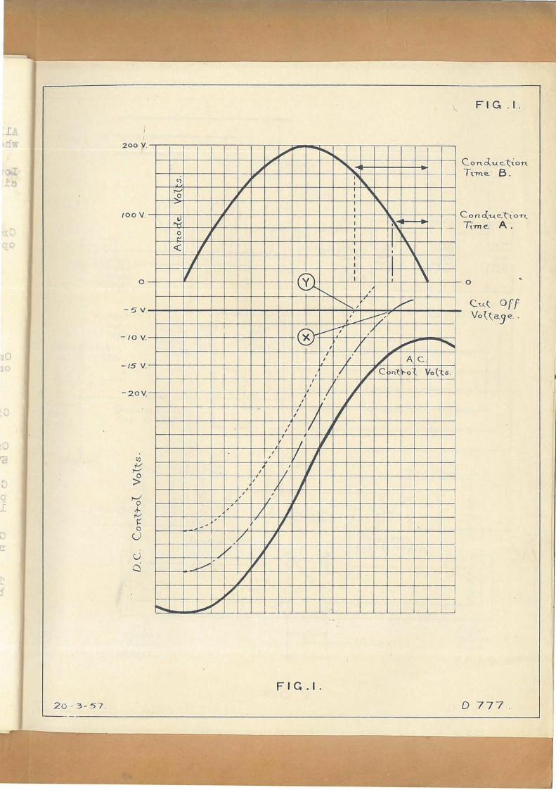
From fig.1 it can be seen that , with A.G. 100v
• ve. occurs twice, once as the voltage rises, the other
as the voltage falls. If, therefore, a steady D.C. is
applied to the grid, the valve will always fire on the
rising side of the curve. To obtain control of the falling
side, the D.C. will have to be modulated with A.O. This
is done by means of t be phase shift (T14/q) and grid
transformers (T11/p/q). The output of the latter is 43vo
and can be seen in fig.1o When no D.C. is applied, the
grid voltage oscillates about zero, thus the valve
conducts for 600/4 of the cycleo The positive peak of the
modulated grid voltage has bee r/fn ifted in phase, so that
it coincides with the zero voltage of the falling +ve
half cycle. By moving the A. ~ . control voltage zero
potential -ve, with respect to the cathode, control over
the whole of the anode+ ve half cycle can be obtainedo
Referring to fig.1 the continuous line
(A.C.control voltage) is shown below the 5v-ve cut-off
line, and therefore the valve will not conduct, since at
no time is the control voltage above lOv-ve. A chain
line shows the resultant position of the modulated control
volta in reducing the D.C. by 15v. Part of the A.O. control
I
l
i
I
I I I
I
n.
I
,,,___ II
, u
I
!

1
-5-
volts is no~ less than 5vo-ve., and reaches this value
at point x. ' The valve will now donduct and continue until
the anode volts reach approx.zero and will do so for each
+ ve half cycle, giving a conduction time""• A further
decrease of 15v D.C. will raise the control voltage to the
~otted position. The valve will now commence to conduct
at point Y, giving a conduction time "B", and so on until
full output voltage is reached.
4) Operation of three valvesier circuit.
A three phase supply is used, and withone
thyratron per phase, this gives half wave rectification
to a U.DaC. (uni-directional current) of approx. equal
R.M.S. voltage to that of the supply phase voltageo
(A moving iron, or dynamometer _instrument is required to
read U.D.C.) The greatest advantage with this system is
that it offers no phasing problems with socket outlets
in the studio.
Only one valve is conducting at any one
time, otherwise there would be a dead short between
two phases. If two anode fuses blow, and there is no
apparent reason for their failure, a "back fire" in one
of the valves can be assumedo
The load is taken from the centre tap of
the common heater transformer winding. This is done
because the valves are directly heated, and the load
-,
-
n.
I '
I
I
, '

-6-
current pasijes through the filaments. If the load was
taken off one side, there would be unequal cur r ent
distribution in the filament causing serious harm. To
reduce voltage drop in the heater transformer , caused by
the load passing through it, the filament voltage is only
2.5v, thus offering a low impedance path to the load
current. (The load current also reduc es the reflected
impedance in the primary).
Having used half wave rectification, there
is no balancing out of current in the neutral, therefore,
the neutral must be able to carry the total lamp load ,
ioe. /"3 times phase current.
Each valve is protected by a fuse and a
choke. The fuse will blow with continuous heavy current,
whilst the choke will reduce large transients. These
heavy transients are always present when switching on
cold lamps, as their cold resistance is approx. ~rd.
of their hot resistance.
The smooth D.C.control voltage is applied
to one side of the grid transformer secondaries (T11/p/q),
the other individual side having the correct phase modulation
for the valve it is to control. This voltage is then fed
via the grid resistor to the grid capacitor, and a voltage
appears across it as a charge.

-7-
At a critical voltage ·, the grid will
allow a f ewl electrons to reach the anode, from the cathode,
and when sufficient velocity is reached, the gas will ionise.
At this poin t , the cathode potential will rise, driving
the grid more pos i tive by the positive feedback obtained
via the short CR, supplied by the g·rid capacitor (0103/p/q)
and resistor (RlOl/p/q)o
The positive feedback is passed through the
grid transformer (under fault cond iti ons it may cause the
latter to burn out) into the control line. If this
feedback :is permitted, "talk" between circuits and valves
will occur. To prevent this, each control line is
decoupled by capacitor 0102/po
it In practice/is f found that a delay is
required when switching from one dimmer preset to another,
so the decoupling capacitor has been increased in value,
thus offering a delay in the rise and fall time of the
control line voltage 9 (i.e.time is required to charge
and discharge the ca p acitor when the control line voltage
varies).
All lamps made in this country are designed
for 50 c/s . operation, and thus, when used on 150 c/s U.DoC. ~i--~ --uJ~ ·~ ,~
they. "sing" o This is caused byj the inductive forming of a
coiled filament. To reduce this noise, a filter system
(0101/p and H11/p) is introduced into each lamp circuit,
thus tending to smooth the output somewhat.

-8-
5) Basic Contr o lo
The cross fader (R112) consists of two
potentiometers connected back to back across 120-160v D.C.
This voltage is adjustable by taps on the main rectifier,
and affects the full-on voltage of the lamps.
Across this floating supply (see figo2)
is connected the blackout pot., the wiper of which is
connec -ted to the neutral, so that the correct bias can be
applied to the valves when the lev ers are in the "off"
position, (ioe. when all levers are down, the wiper is
adjusted so that all valves are j u st cut off)o
Two master faders are fed from the cross
fader, each having one end connected to+ veo The othe r
end of the master faders being connected to their respective
cross f ader wiper, and the common connections of the
control unitso The master fader wiper feeds its master
blackout switch, which in turn feed s the respective control
unit switches, via the preset relays.
Each circuit bas two control units, providing
betwe en them the required grid voltageo When the right preset
is being used ·, the left preset must be at full + ve potential,
and vice versao This achieved by the function of the cross
fader always ensuE! E-~-~hat, as the voltage across the left ~-~~~~~~)
strips rises, i or vice versa. This ensures a smooth proportional
on.
f

-9-
change from one preset to another.
The grid control voltage is taken from the
mid-point of two equal resistors (R 102/p/q) connecting the
wipers of the left and right control units together. They,
in conjunction with the control line decoupling capacitor
(C 102/p) offer the required switching delayo
6) Three Scene Preset.
The Cross, LeJ t and Right faders, are
remotely operated from the control desk, and will be found
on the Auxiliary Bank.
As two control units must always be connected
for any one circuit, a 3 scene preset board is provided
with two dummy units. This enables an operator to accidently
select a preset already in use, without causing any trouble.
(He must not, however, cross fade to preset which is already
in use). A warning light informs that a preset already in
use has been selected.
If "snap" changes are required between
presets, the preset selector on the opposite side of the cross
fader to that being used , is set to a dummy unit, leaving
all the presets available on one switch o
Each preset is brought in by a coupler strip,
(housed in a wooden box below the control desk) and actuated
by six 3,000 type relays. ON NO ACCOUNT SHOULD THESE RELAYS
OR COUPLERS BE OPERATED BY HAND, . EXCEPT WITH THE MAIN SUPPLIES
OFF.
on
I I

t
)
-10-
The master blackout switches operate relays
which f e ed the control unit bars from the preset relay
contacts. Under normal conditions, two of the coupler
strips per bar will be in the operated position.
7). Dead Patch _~nd Blackout.
The dead patch switch operates the contactor
controlling the anodes of valves in the respective patching
area, of which there are four. The D.B.O. (in the form of
a key switch) operates all the contactors together with the
5 kw. and switched only circuits.
Each preset has two blackout switches, (one
for channel switches in the "up" position, the other for
"down")o The "mid" position is "off", "down" is "normal",
and "up 11 connects the respective electronic and switched
only blackout relays to the practical ring main (15v DoC.)
around the studio floor.
The blackout switches are always live, their
outputs being selected by the preset selector switcheso
The electronic channels are kept separate so that there is
no time delay in waiting for the blackout relays to come
in, when changing to a new preset.
Switched only channels have their connections
broken down to individual wires, thus preventing feedback
between presets. The blackout coupler relays facilitate
on.
f

-11-
dead patching '.
Secondary control of switched only channels
is provided on the patch panelo If, however, the master
switch is left in the on position, the desk operator cannot
over-ride the patch panelo
The "Lap Change" switch operates the switched only
circuits in the selected preseto The actual changeover
taking place at two different predetermined positions in
relation to the cross fader. One is that the new selected
preset comes on as the cross fader starts to travel, and
the old lighting extinguishes as the cross fader ends its
travel. The second conditions of operation, i s for the new
light to appear when the cross fader is at 25% of its travel,
and the old light to go out when 75% of its travel is
reached.
8) Motor Speed.
When the "Motorn switch is on, a relay closes
and energises the motor field. At the same time a
potent i ometer is made live and thus by an y one of the speed
relays being operated, the armature will be fed, via a series
field winding, with a constant voltage. The motor is a
50v doc o compound wound machine, having constant speed
characteristics for varying loads, at spe eds in proportion
to the applied armature podo
The motor turns a uni-directional shaft
on.

l
0
-12-
supplying motive power to the clutch plates for 4,5kw.
resistance dimmers, two master and one cross fader.
9) Faders and 5kw. Dimmers.
The cross f ader i s operated by a switch
on the control desk. This feeds two relays via wip er
travel limit switches on the cross fader frameworko The
relays are to reduce the current t hat would be passed by
the switch, as double clutches are used to obtain the
required torqueo Also mounted on the cross fader frame
are four limit switches which operate the switched only
circuits. (See section 7, para 4o) ·A meter indicates
the position of the cross ~ader.
Two separate polarised relays operate
the left and right master faders. These are controlled
with dimmer levers on the centre section of the control
desk , by feeding a selected voltage from a potentiometer
winding. A similar potentiometer on the fader frame
feeds back a voltage, and the two meet at the polarised
relay. If these two voltages are not equal, a current
flows in one or the other direction, and the relay
operates. The clutches drive the dimmer until a state
of balance is reached.
The 2,000 ohm. resistance is to prevent
the wiper becoming temporarily disconnected from the
strip, due to dust or a broken winding. If dust is
on.

-13-
present, the dimmer will agitate until the obstacle is
removed. If th e stri p is broken, the dimmer will move
to the full-on position.
The rectifier acros s the clutch coils
is to suppress the field discharge.

-14-
TROUBLE-SHOOTING.
No light.
Reduced light,i.e. 1 or 2 valves out.
Reduced light, but repeated blowing of ano de fuses.
One or two valves out in adjacent circuits.
Wing c ompletely dead (includin g heat ers).
Wi ng dea d , but heaters on.
Dimming erratic.
Check circuits by using load check. Check anode fuses but do not
replace more than once.
Check anode fuses, and valves.
Check for overload.
Check contactor f i ngers, i.e. fingers not making good contact.
Check valve heater fuses.
Verify Patchin g Sect.Dea d switch is on. If "on" then put "off" and "on" deliberately to check by ear that the bank contactor works. If contactor is not working, check valv e tim e delay fuses (pair). If fuses are withdrawn or replaced, some delay up to 2 min. will result, before contactor can be closed. If fus e s O.K. then the back centre covers must be removed. If time delay valve is not glowing, then replace. Valve not at fault, t h en check relay is closed and making conta c t. Relay O.K. then examine 300 amp. contactor.
Check p hase shift fuses on bank ce n tre panel, but put the appropriate Patching "Sect Dead" down first.
n.

-15-
All circuits up at low light whether switched on or not.
Low light output on all circuits with dimmer levers up.
Crossover fader will not operate a preset.
One circuit fails to go right on one or more presets.
Circuit has very fast response.
One or more valves refuse to go out.
Check D.O.output fuseso
Check 3 ph.input fuseso to D.C. rectifier on centre panel Bank 1.
Check that at least two coupler strips have operated when the selector is switched to the offending preset. NEVER operate the selector relays by hand, unless the supply is switched off. With supply off, check selector relay contacts and coupler coils.
Check R102/p/q for value and toleranceo (There are 4 per circuit, one ~er preset plus a dummy)o
Check decoupling capacitor Cl02/p.
Check position of "Blackout Adjust. pot.
Circuit comes up full at certain Check dimmer strip for positions of the dimmer dirt or gaps in winding. lever.
Circuit "jum~' when dimmer not being operated.
Two anode fuse per circuit blow for no apparent reason.
Check valves in respective circuit.
Check valves for backfi11ingo
I.
on.
o-n__
f
200 '
Cl) ~ r---' ~' _o
100 V. - I cv / ~
0 J r'
< I j
I 0
-5 V.
' I
-10 V.
-15 V.
[..1
II)
V r--'
0 >
C ~ I ,
I , .,j.. ,
~ , r
0 ,
cJ '/
c.) ~/
r
a /
1/ /
""'-- --V'
20 - 3-57 .
~~ -~""-
~ ,
"II~ , :~\. I
""' I I
' I
i'-I ,, I I
I I I
I I I
© I I I
i"---... ,
I'---;-.._ I ./ I i..----
.....--;:, /
0 ........... ~ / V
I J ~ I
1/ /r' I
I I / C ,n'(
' i~ I I I
I ' If ,, I
I / , I I J I
I ,
I I J I . I
' I I I I
' I I /
J j ,
I
I ./ ,
FIG.I.
;..
-\.
\ \
' .,.,,.....
--A. C .
t-o 11/o{
\
-
-
~
s.
FIG. I.
C.ond.-uc.\,:on. T-1.-m.e.· B.
Con d..-uc.t,·o-n.. Ti.m.e.. A.
0
0 777.

R. ----------T Phase . W.----------,-
Fi (i e.tCap .
C 101/p
8
He.a.t._e..."r Tt-a.n.-s . Ti2/p
Loa.cl...
PotR.103/p/<j.
Tra..n..s . Tn/p/'j,
---1~-------;1 _- _ - - _I
Con.tt-o { U..n.-i.t.
Ct-oss F a cl..e.t--. R 112 L.~--------~e-.:...:..;=---: ,,--r I
L -- -- - --- - -'
Ph_a..se....
W .
BaXa..nc~n'J R.e.s . R... 102 tP/ci
Le.fr:: f'1 d.S \ E!.. T"' r a..d_e.'t-. '---t--- ' - N e.u..tt-a..1 .
RIII/L. +
FIG. 2. /0 - 3 - 57 .
FIG .2.
B.
R,,jht Ma_.s t~.} Fad_e.:r-. R Ill I R.
D 770


![Smoothed Analysis of the Condition Numbers and Growth Factors … · 2009-11-14 · the algorithm performs poorly. (See also the Smoothed Analysis Homepage [Smo]) Smoothed analysis](https://static.fdocuments.us/doc/165x107/5e9273249dce0d4d044b7179/smoothed-analysis-of-the-condition-numbers-and-growth-factors-2009-11-14-the-algorithm.jpg)


