
Stormwater Quality Management Plan - Yaroomba Beach · development proposal over the site is for...
23
Yaroomba Village and International Resort, SQMP; Revision B; 23.03.2017 | The SMEC Group | 1 Yaroomba Village and International Resort Stormwater Quality Management Plan 23 March 2017 www.smec.com
Transcript of Stormwater Quality Management Plan - Yaroomba Beach · development proposal over the site is for...

Yaroomba Village and International Resort, SQMP; Revision B; 23.03.2017 | The SMEC Group | 1
Yaroomba Village and International Resort
Stormwater Quality Management Plan
23 March 2017
www.smec.com

Yaroomba Village and International Resort, SQMP; Revision B; 23.03.2017 | The SMEC Group | 1
DOCUMENT/REPORT CONTROL FORM
File Location Name: I:\Projects\30031110\005_Ops\Water
Resources\Report\SQMP\30031110_Yaroomba_SQMP_RevB_20170314.docx
Project Name: Yaroomba Village and International Resort, SQMP
Project Number: 30031110
Revision Number: Rev B
Revision History
Revision # Date Prepared by Reviewed by Approved for Issue by
Rev A 12.09.2013 Leon Evans Ashley Zanetti Chris Green
Rev B 23.03.2017 Kellie Thomsen Brendon Bolt Carl Wilkinson
Issue Register
Distribution List Date Issued Number of Copies
Sekisui House x1 electronic
Office Library [Sunshine Coast] x1 electronic
SMEC Project File x1 electronic
SMEC Company Details
[SMEC]
Level 1, Building C, 6 Innovation Parkway, Birtinya, QLD, 4575
Tel: +07-3029 6700
Email: [email protected] Website: www.smec.com
The information within this document is and shall remain the property of:
Sekisui House and SMEC.

Yaroomba Village and International Resort, SQMP; Revision B; 23.03.2017 | The SMEC Group | 2
IMPORTANT NOTICE
This report is confidential and is provided solely for the purposes of outlining stormwater management measures for the property owned by Sekisui House at David Low Way, Yaroomba. This report is provided pursuant to a Consultancy Agreement between SMEC Australia Pty Limited (“SMEC”) and Sekisui House under which SMEC undertook to perform a specific and limited task for Sekisui House . This report is strictly limited to the matters stated in it and subject to the various assumptions, qualifications and limitations in it and does not apply by implication to other matters. SMEC makes no representation that the scope, assumptions, qualifications and exclusions set out in this report will be suitable or sufficient for other purposes nor that the content of the report covers all matters which you may regard as material for your purposes.
This report must be read as a whole. The executive summary is not a substitute for this. Any subsequent report must be read in conjunction with this report.
The report supersedes all previous draft or interim reports, whether written or presented orally, before the date of this report. This report has not and will not be updated for events or transactions occurring after the date of the report or any other matters which might have a material effect on its contents or which come to light after the date of the report. SMEC is not obliged to inform you of any such event, transaction or matter nor to update the report for anything that occurs, or of which SMEC becomes aware, after the date of this report.
Unless expressly agreed otherwise in writing, SMEC does not accept a duty of care or any other legal responsibility whatsoever in relation to this report, or any related enquiries, advice or other work, nor does SMEC make any representation in connection with this report, to any person other than Sekisui House .Any other person who receives a draft or a copy of this report (or any part of it) or discusses it (or any part of it) or any related matter with SMEC, does so on the basis that he or she acknowledges and accepts that he or she may not rely on this report nor on any related information or advice given by SMEC for any purpose whatsoever.

Yaroomba Village and International Resort, SQMP; Revision B; 23.03.2017 | The SMEC Group | 3
TABLE OF CONTENTS
INTRODUCTION .............................................................................................................................6
1.1. Site Characteristics ............................................................................................................ 6
2. STORMWATER QUALITY MANAGEMENT .................................................................................8
2.1. Design Objectives .............................................................................................................. 8 2.2. Stormwater Quality Strategy ............................................................................................. 8 2.3. Modelling Approach .......................................................................................................... 9
MUSIC Parameters .................................................................................................... 9 Catchment Areas .....................................................................................................10 MUSIC Model Layout ...............................................................................................10
2.4. Treatment Measures .......................................................................................................12
Rainwater Harvesting Tanks ....................................................................................12 Bioretention Swales .................................................................................................12 Bioretention Basins .................................................................................................12 WSUD Measures ......................................................................................................13
2.5. Music Results ...................................................................................................................15
3. CONSTRUCTION MANAGEMENT ........................................................................................... 16
4. OPERATIONAL PHASE STORMWATER MANAGEMENT ............................................................ 17
5. CONCLUSION AND RECOMMENDATIONS .............................................................................. 18
6. REFERENCES ......................................................................................................................... 19
APPENDIX A SITE LAYOUT ...................................................................................................... 20

Yaroomba Village and International Resort, SQMP; Revision B; 23.03.2017 | The SMEC Group | 4
LIST OF FIGURES
Figure 0-1: Locality Plan (Source: GoogleMaps 2017) .............................................................................. 7 Figure 2-1: Schematic of Proposed Treatment Strategy .......................................................................... 8 Figure 2-2: MUISC Model Layout ...........................................................................................................11 Figure 2-3: Typical Bio-retention basin Cross-section (FAWB 2009) ......................................................13 Figure 2-4: Water Quality Catchment and Indicative Locality Plan........................................................14

Yaroomba Village and International Resort, SQMP; Revision B; 23.03.2017 | The SMEC Group | 5
LIST OF TABLES
Table 2-1 MUSIC Rainfall-runoff parameters ........................................................................................... 9 Table 2-2 MUSIC Base and Storm Flow Concentration Parameters ........................................................ 9 Table 2-3 MUSIC Catchments .................................................................................................................10 Table 2-4 Proposed WSUD measures to achieve WQO’s .......................................................................13 Table 2-5 MUSIC Results ........................................................................................................................15
Yaroomba Village and International Resort, SQMP; Revision B; 23.03.2017 | The SMEC Group | 6
1. INTRODUCTION
SMEC has been commissioned by Sekisui House to develop a Stormwater Quality Management Plan (SQMP) to support a Material Change of Use application for the development of a development site at David Low Way, Yaroomba known as the Yaroomba Village and International Resort (formerly the Beachside Precinct).
The Beachside Precinct was part of the Historical Hyatt Master Plan, located on the eastern side of the David Low Way in Yaroomba. The original plans for the site developed in 2005 included a resort and gated residential subdivision.
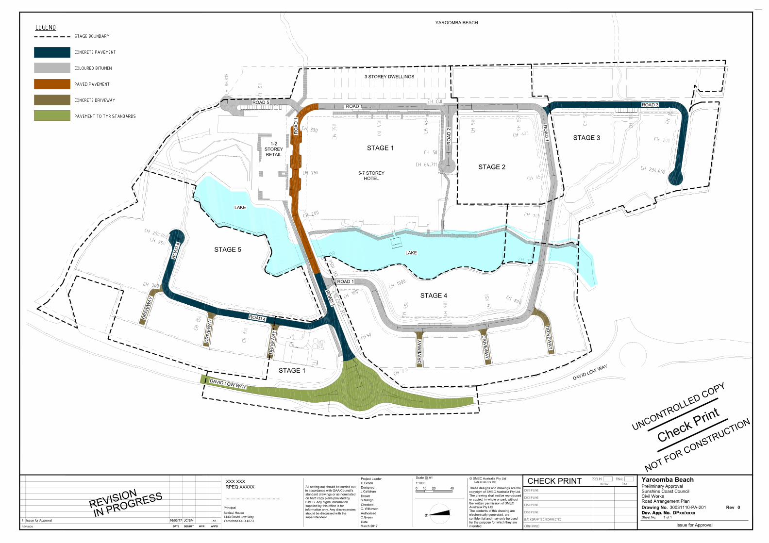
The plan for the site includes a revised density residential development, centred around a major 5-star (6-star green rating) international resort hotel equipped with public amenities. The development proposal over the site is for Stage 1 (refer Appendix A). This SQMP has been prepared to address the entire development site Stages 1 to 5. Whilst the development intent of Stage 1 is known, the anticipated development intensities for the remaining stages 2 to 5 were represented.
The Pollution Load Reduction Targets have been derived from the “Stormwater Management Code” of the Sunshine Coast Planning Scheme 2014. From this, the load based Water Quality Objectives (WQO’s) stipulated in the State Planning Policy – July 2014 (DSDSIP) for the South East Queensland region will be adopted for the site. The purpose of this SMP is to identify the stormwater quality and detention options required to be implemented within the site to achieve elements of these codes. The objectives of this SMP are to:
• Ensure the proposed development maintains or improves the environmental values ofthe receiving waters within the receiving catchment throughout the operational phase;
• Consider suitable Stormwater Quality Improvement Devices (SQID’s) based on WaterSensitive Urban Design (WSUD) principles;
• Recommend an appropriate stormwater treatment strategy for the proposeddevelopment that complies with Sunshine Coast Council (SCC) water quality objectives;
A previous Stormwater Quality Management Plan (12 September 2013) was prepared by SMEC for the previous development layout over the site. This report and its recommendations supersedes the SMEC (2013) report.
1.1. Site Characteristics
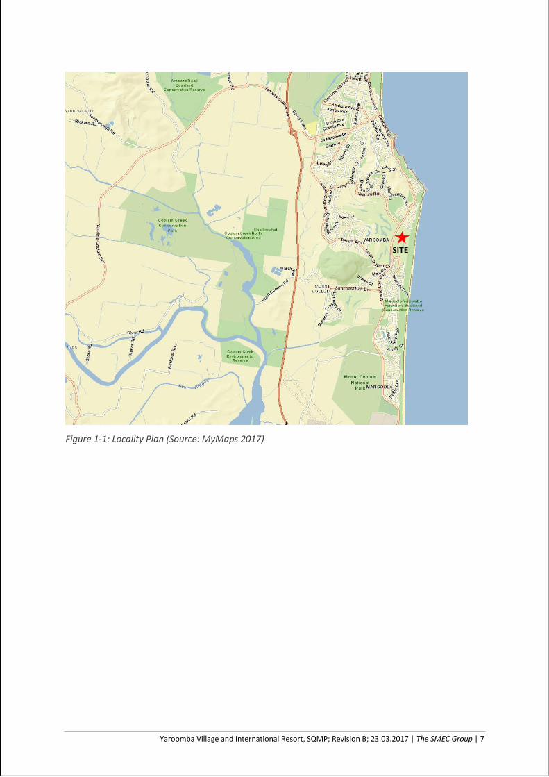
The location of the proposed development site is shown in Figure 1-1.
The proposed developed site is located on the eastern side of the David Low Way at Yaroomba, and is bound by an existing residential estate (Beachside South) in the south, Warragah Parade to the north and the ocean to the east.
The catchment affecting the site itself, on the eastern side of David Low Way is approximately 49 ha and elevations range from 23.0 to 2.5m AHD. Steep slopes are seen in the dunal area, however, the area of development site is predominately flat. Runoff from the site flows across David Low Way to the west, before flowing south across Tanah Street to an open drain which travels south through to Suncoast Drive and the Mt Coolum golf course. A larger catchment (318 ha) exists on the western side of David Low Way and contributes to Tanah Street culverts.
The land-use of the site previously formed part of the Hyatt Regency golf course, but construction works stemming from previous applications over the site has seen the southern portion of the site be developed with residential allotments, entry road and main lake already having been constructed.
The proposed development layout is provided in Appendix A.
Yaroomba Village and International Resort, SQMP; Revision B; 23.03.2017 | The SMEC Group | 7
Figure 1-1: Locality Plan (Source: MyMaps 2017)
SITE

Yaroomba Village and International Resort, SQMP; Revision B; 23.03.2017 | The SMEC Group | 8
2. STORMWATER QUALITY MANAGEMENT
2.1. Design Objectives
Water quality objectives or performance criteria for the proposed development are those stipulated in the State Planning Policy – July 2014 (DSDSIP) for the South East Queensland region. The applicable water quality design objectives for the site are shown in below, which specify that the following load-reduction targets must be achieved when comparing the post-developed unmitigated site to the post-developed mitigated site:
80% reduction in Total Suspended Solids (Sediment) (TSS);
60% reduction in Total Phosphorus (TP);
45% reduction in Total Nitrogen (TN); and
90% reduction in Gross Pollutants (GP).
As pollutant export modelling typically focuses on nutrient and sediment transport during the post-construction phase, these pollutants will be the main focus of modelling assessments.
2.2. Stormwater Quality Strategy
The treatment strategy flow chart for the site is outlined below in Figure 2-1. It is proposed that rainwater from roofed areas will be collected in rainwater tanks and re-used for irrigation, with overflows and all other runoff from all developable areas of the site be directed to a bioretention swale or bioretention basin prior to discharging into the central lake. It is proposed that the water quality objectives will be achieved prior to entering the central lake. There will be some minor catchments which cannot be directed to a treatment device.
Figure 2-1: Schematic of Proposed Treatment Strategy

Yaroomba Village and International Resort, SQMP; Revision B; 23.03.2017 | The SMEC Group | 9
2.3. Modelling Approach
MUSIC Parameters
An assessment of stormwater runoff quality from the proposed development site has been assessed using the Cooperative Research Centre for Catchment Hydrology’s (CRCCH) Model for Urban Stormwater Improvement Conceptualisation (MUSIC). MUSIC is a decision support tool, used to plan and design appropriate urban stormwater management systems at the conceptual level. MUSIC Version 6.2, released in 2016, was used in this assessment.
Climate data for the catchment was sourced from the MUSIC model database. The rainfall and evaporation data template for this site has been based on data from Nambour DPI from 1/1/1989- 31/12/1998 with six (6) minute rainfall duration.
The “MUSIC Modelling Guidelines” (Water By Design, 2010) were used as the basis for constructing the MUSIC model. The default parameters of the MUSIC model were used in representing the treatment nodes (where applicable). Table 2-1 and Table 2-2 outline the adopted source node parameters that were used in the MUSIC model.
Table 2-1 MUSIC Rainfall-runoff parameters
Parameter Urban
Rainfall Threshold (mm) 1
Soil Capacity (mm) 500
Initial Storage (%) 10
Field Capacity 200
Infiltration Capacity Coefficient a 211
Infiltration Capacity Coefficient b 5
Initial Depth (mm) 50
Daily Recharge Rate (%) 28
Daily Base Flow Rate (%) 27
Daily Deep Seepage Rate (%) 0
Table 2-2 MUSIC Base and Storm Flow Concentration Parameters
Land Use category Log10 TSS (mg/L) Log10 TP (mg/L) Log10 TN (mg/L)
Mean Std Dev Mean Std Dev Mean Std Dev
Roof Baseflow 0.00 0.00 0.00 0.00 0.00 0.00
Stormflow 1.3 0.39 -0.89 0.31 0.26 0.23
Road Baseflow 1.00 0.34 -0.97 0.31 0.20 0.20
Stormflow 2.43 0.39 -0.30 0.31 0.26 0.23
Ground Baseflow 1.00 0.34 -0.97 0.31 0.20 0.20
Stormflow 2.18 0.39 -0.47 0.31 0.26 0.23
Yaroomba Village and International Resort, SQMP; Revision B; 23.03.2017 | The SMEC Group | 10
Catchment Areas
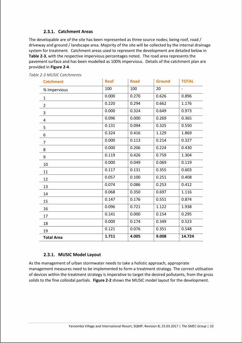
The developable are of the site has been represented as three source nodes; being roof, road / driveway and ground / landscape area. Majority of the site will be collected by the internal drainage system for treatment. Catchment areas used to represent the development are detailed below in Table 2-3, with the respective impervious percentages noted. The road area represents the pavement surface and has been modelled as 100% impervious. Details of the catchment plan are provided in Figure 2-4.
Table 2-3 MUSIC Catchments
Catchment Roof Road Ground TOTAL
% Impervious 100 100 20 -
1 0.000 0.270 0.626 0.896
2 0.220 0.294 0.662 1.176
3 0.000 0.324 0.649 0.973
4 0.096 0.000 0.269 0.365
5 0.131 0.094 0.325 0.550
6 0.324 0.416 1.129 1.869
7 0.000 0.113 0.214 0.327
8 0.000 0.206 0.224 0.430
9 0.119 0.426 0.759 1.304
10 0.000 0.049 0.069 0.119
11 0.117 0.131 0.355 0.603
12 0.057 0.100 0.251 0.408
13 0.074 0.086 0.253 0.412
14 0.068 0.350 0.697 1.116
15 0.147 0.176 0.551 0.874
16 0.096 0.721 1.122 1.938
17 0.141 0.000 0.154 0.295
18 0.000 0.174 0.349 0.523
19 0.121 0.076 0.351 0.548
Total Area 1.711 4.005 9.008 14.724
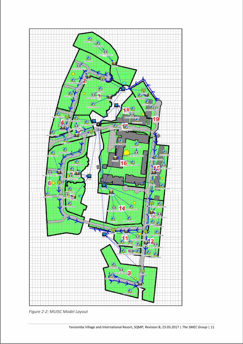
MUSIC Model Layout
As the management of urban stormwater needs to take a holistic approach, appropriate
management measures need to be implemented to form a treatment strategy. The correct utilisation
of devices within the treatment strategy is imperative to target the desired pollutants, from the gross
solids to the fine colloidal partials. Figure 2-2 shows the MUSIC model layout for the development.
Yaroomba Village and International Resort, SQMP; Revision B; 23.03.2017 | The SMEC Group | 11
Figure 2-2: MUISC Model Layout
Yaroomba Village and International Resort, SQMP; Revision B; 23.03.2017 | The SMEC Group | 12
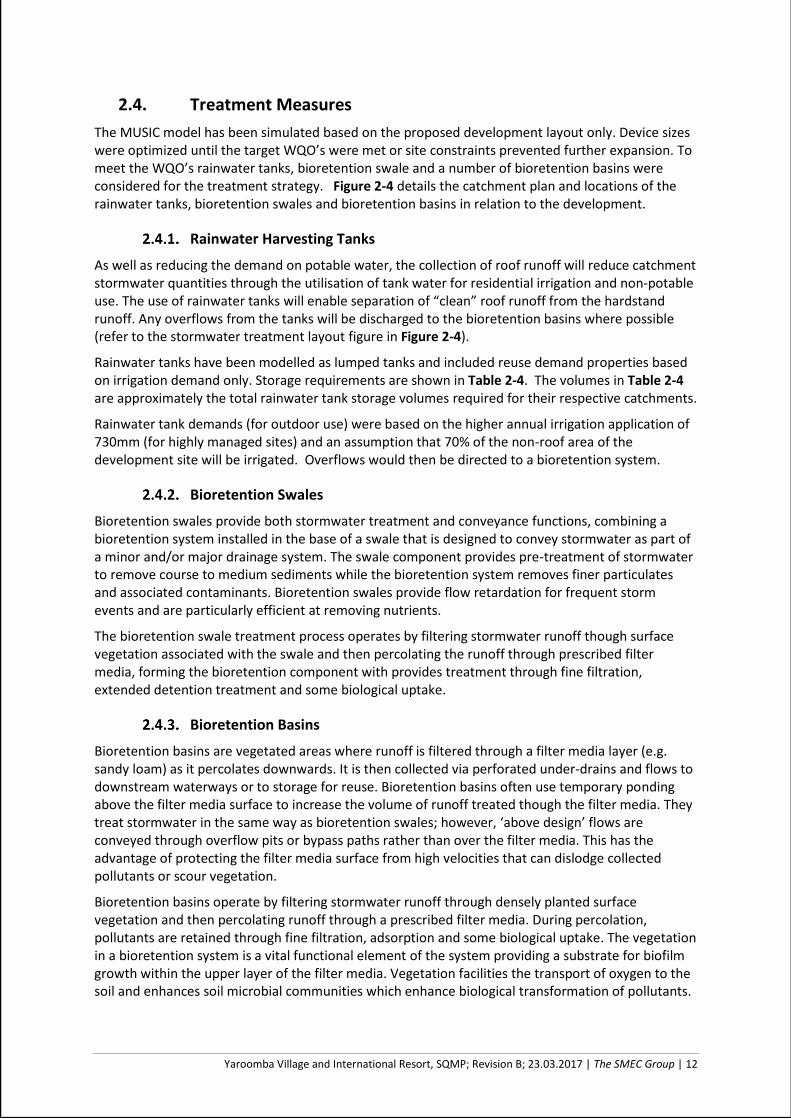
2.4. Treatment Measures
The MUSIC model has been simulated based on the proposed development layout only. Device sizes were optimized until the target WQO’s were met or site constraints prevented further expansion. To meet the WQO’s rainwater tanks, bioretention swale and a number of bioretention basins were considered for the treatment strategy. Figure 2-4 details the catchment plan and locations of the rainwater tanks, bioretention swales and bioretention basins in relation to the development.
Rainwater Harvesting Tanks
As well as reducing the demand on potable water, the collection of roof runoff will reduce catchment stormwater quantities through the utilisation of tank water for residential irrigation and non-potable use. The use of rainwater tanks will enable separation of “clean” roof runoff from the hardstand runoff. Any overflows from the tanks will be discharged to the bioretention basins where possible (refer to the stormwater treatment layout figure in Figure 2-4).
Rainwater tanks have been modelled as lumped tanks and included reuse demand properties based on irrigation demand only. Storage requirements are shown in Table 2-4. The volumes in Table 2-4 are approximately the total rainwater tank storage volumes required for their respective catchments.
Rainwater tank demands (for outdoor use) were based on the higher annual irrigation application of 730mm (for highly managed sites) and an assumption that 70% of the non-roof area of the development site will be irrigated. Overflows would then be directed to a bioretention system.
Bioretention Swales
Bioretention swales provide both stormwater treatment and conveyance functions, combining a bioretention system installed in the base of a swale that is designed to convey stormwater as part of a minor and/or major drainage system. The swale component provides pre-treatment of stormwater to remove course to medium sediments while the bioretention system removes finer particulates and associated contaminants. Bioretention swales provide flow retardation for frequent storm events and are particularly efficient at removing nutrients.
The bioretention swale treatment process operates by filtering stormwater runoff though surface vegetation associated with the swale and then percolating the runoff through prescribed filter media, forming the bioretention component with provides treatment through fine filtration, extended detention treatment and some biological uptake.
Bioretention Basins
Bioretention basins are vegetated areas where runoff is filtered through a filter media layer (e.g. sandy loam) as it percolates downwards. It is then collected via perforated under-drains and flows to downstream waterways or to storage for reuse. Bioretention basins often use temporary ponding above the filter media surface to increase the volume of runoff treated though the filter media. They treat stormwater in the same way as bioretention swales; however, ‘above design’ flows are conveyed through overflow pits or bypass paths rather than over the filter media. This has the advantage of protecting the filter media surface from high velocities that can dislodge collected pollutants or scour vegetation.
Bioretention basins operate by filtering stormwater runoff through densely planted surface vegetation and then percolating runoff through a prescribed filter media. During percolation, pollutants are retained through fine filtration, adsorption and some biological uptake. The vegetation in a bioretention system is a vital functional element of the system providing a substrate for biofilm growth within the upper layer of the filter media. Vegetation facilities the transport of oxygen to the soil and enhances soil microbial communities which enhance biological transformation of pollutants.
Yaroomba Village and International Resort, SQMP; Revision B; 23.03.2017 | The SMEC Group | 13
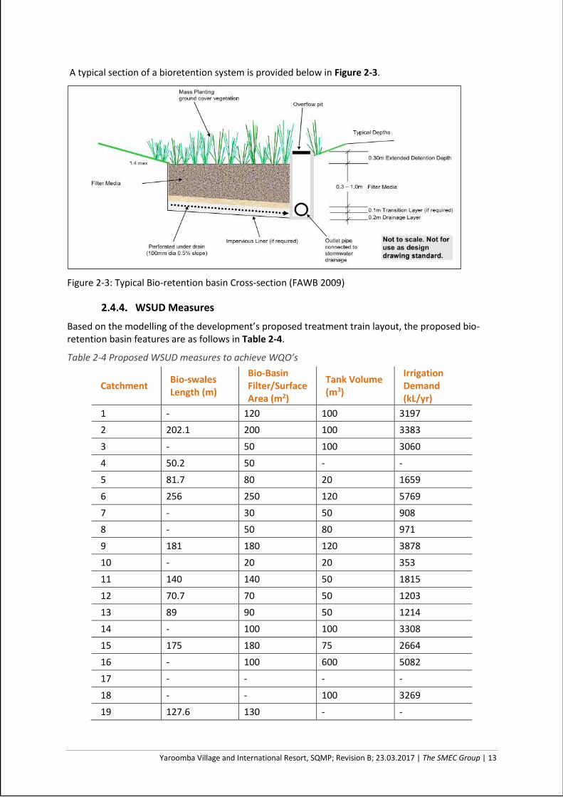
A typical section of a bioretention system is provided below in Figure 2-3.
Figure 2-3: Typical Bio-retention basin Cross-section (FAWB 2009)
WSUD Measures
Based on the modelling of the development’s proposed treatment train layout, the proposed bio-retention basin features are as follows in Table 2-4.
Table 2-4 Proposed WSUD measures to achieve WQO’s
Catchment Bio-swales Length (m)
Bio-Basin Filter/Surface Area (m2)
Tank Volume (m3)
Irrigation Demand (kL/yr)
1 - 120 100 3197
2 202.1 200 100 3383
3 - 50 100 3060
4 50.2 50 - -
5 81.7 80 20 1659
6 256 250 120 5769
7 - 30 50 908
8 - 50 80 971
9 181 180 120 3878
10 - 20 20 353
11 140 140 50 1815
12 70.7 70 50 1203
13 89 90 50 1214
14 - 100 100 3308
15 175 180 75 2664
16 - 100 600 5082
17 - - - -
18 - - 100 3269
19 127.6 130 - -

Yaroomba Village and International Resort, SQMP; Revision B; 23.03.2017 | The SMEC Group | 14
Figure 2-4: Water Quality Catchment and Indicative Locality Plan

Yaroomba Village and International Resort, SQMP; Revision B; 23.03.2017 | The SMEC Group | 15
2.5. Music Results
Table 2-5 presents the residual pollutants draining from the site after treatment as modelled in MUSIC. These results demonstrate that the target for reduction of Total suspended solids, Total Nitrogen and Total Phosphorous was achieved for the treatment train proposed for the development. The proposed stormwater quality treatment strategy is therefore considered to represent best management practice for this development. No additional measures are therefore required to satisfy the water quality objectives at this stage.
Table 2-5 MUSIC Results
Pollutants Sources Residual Reduction (%)
Target Reduction
Compliance
Total Suspended Solids (kg/yr) 21200 3920 81.5 80
Total Phosphorus (kg/yr) 45.5 12.7 72.2 60
Total Nitrogen (kg/yr) 283 130 54.1 45
Gross Pollutants (kg/yr) 2650 97.7 96.3 90
Yaroomba Village and International Resort, SQMP; Revision B; 23.03.2017 | The SMEC Group | 16
3. CONSTRUCTION MANAGEMENT
The management of the site during the construction phase is an important step in ensuring water quality standards are achieved. Implementation of best practice Erosion and Sediment Control techniques is imperative to managing the quality of runoff affected by construction works.
The following points provide general guidance on the management of stormwater during the construction phase. Erosion and Sediment Control Management Plans should be provided during the Operational Works application stage in accordance with Council’s Erosion and Sediment Control Guideline.
1. Establish a single stabilised entry/exit point for the site works;
2. Construct a shake-down grid at the entrance to facilitate the removal of sediment fromtrucks leaving the site. The access road extending from the end of existing road or kerbto the grid should comprise a 150-200mm deep pad of 40mm crushed rock;
3. Install sediment fences along the lower boundaries of the site;
4. Install a suitably sized sediment basin (as required) and construct contour drains / bundsto direct disturbed runoff to the sediment basin;
5. Install bins and/or wind-proof litter areas on-site to minimise the dispersion of grosspollutants;
6. Maintain on site spare materials necessary for the emergency repair of all erosioncontrol devices. This includes silt fences, clean crushed rock for reapplication to theentrance road and for replacement of rock within temporary drainage channels;
7. Following each days construction works, ensure that any material on road surfaces isswept from the road, and not permitted to be washed down the gutters and pipeddrainage systems.
8. Quality of pooled water within sediment basins are to be monitored prior to dewatering,sufficient time should be given to allow sediment to settle (possible with the assistanceof a suitable flocculent if necessary) &/or filtering during pumping operations.
9. Final establishment of bioretention systems should not occur until full stabilisation ofupstream catchment has occurred; preferably these should be temporarily turfed duringthe maintenance period while dwelling construction is occurring.
It shall be the responsibility of the developer, through their principal contractor, to ensure that temporary sediment and erosion controls are installed and maintained correctly.
Experience shows that the critical periods in the life of WSUD vegetated stormwater systems are the
construction and establishment phases. The timing and approach to these systems must be carefully
considered to ensure successful establishment and long-term performance. Bioretention systems
are now common stormwater treatment devices for new urban developments in South East
Queensland. Successful construction and allowing adequate time for the systems to establish is
critical to their long-term performance and function. Construction of the system is also linked to
having suitable bioretention designs in place to ensure, civil contractors have appropriate plans to
construct to. Applying due care in the design and construction phase will ensure the function of the
system whilst also keeping on-going maintenance to a minimum. It is highly recommended that the
constructed activities be completed in accordance with the Construction and Establishment
Guidelines: Swales, Bioretention Systems and Wetlands (Apr 2010).
Yaroomba Village and International Resort, SQMP; Revision B; 23.03.2017 | The SMEC Group | 17
4. OPERATIONAL PHASE STORMWATER MANAGEMENT
The bioretention systems will be donated to Council, who as the asset custodian, will be responsible
for the on-going maintenance of the water quality devices. Maintenance for the bioretention basin
may involve the following:
1. Scheduled inspections;
2. Removal of noxious plants or weeds;
3. Maintaining the desired vegetation;
4. Repairing erosion;
5. Unblocking inlets and outlets;
6. Removing litter and debris;
7. Managing algal or moss growth;
8. Maintaining the permeability of the filtration.
Operations and maintenance should be conducted in accordance with the Maintaining Vegetated
Stormwater Assets (Feb 2012) guideline.

Yaroomba Village and International Resort, SQMP; Revision B; 23.03.2017 | The SMEC Group | 18
5. CONCLUSION AND RECOMMENDATIONS
This report has aimed to satisfactorily address the requirements of SCC’s Stormwater Management Code, with respect to addressing stormwater quality in order to support the required Material Change of Use over the site at David Low Way, Yaroomba.
The water quality treatment strategy for the site includes the collection of all surface flows directed to a bioretention swale or bioretention basin, with roof water being collected via a rainwater tank and re-used for irrigation. Detailed modelling using the MUSIC software has demonstrated that through the use of the proposed treatment strategy, the runoff from the site meets water quality objectives for pollutant load reduction. Therefore, the proposed treatment strategy is recommended as best management practice for the proposed development.
This plan demonstrates that effective treatment of stormwater at the proposed development can be achieved through the integration of Water Sensitive Urban Design (WSUD) and non-worsening principles. Through the incorporation of rainwater tanks and bioretention system, the plan successfully demonstrates:
• Compliance with the requirements of State Planning Policy and SCC Load BasedObjectives.
• Ecological sustainability in terms of the development’s impact upon receiving waters andthe viability of the proposed site development;
This SQMP has been prepared to address the entire development site Stages 1 to 5. Whilst the development intent of Stage 1 is known, the anticipated development intensities for the remaining Stages 2 to 5 were represented. It is recommended that this report be updated to align with the actual development layouts of Stages 2 to 5 as they area developed (and Stage 1 should it be altered).

Yaroomba Village and International Resort, SQMP; Revision B; 23.03.2017 | The SMEC Group | 19
6. REFERENCES
[SCC, 2014], Stormwater Management Codes;
[Queensland Government, 2014], State Planning Policy.
[Queensland Government, 2010], Urban Stormwater Quality Planning Guidelines.
[QUDM, 2013] Natural Resources and Water, Queensland Urban Drainage Manual – ThirdEdition, 2013.
[WD, 2006], Water by Design, Water Sensitive Urban Design (WSUD) Technical DesignGuidelines for Southeast Queensland, 2006.
[WD, 2010a], Water by Design, MUSIC Modelling Guidelines for South East Queensland, 2010.
[WD, 2010b], Water by Design, Deemed to comply solutions - Stormwater Quality Management,2010.
[WD, 2014], Water by Design – Bioretention Technical Design Guidelines, Version 1.1.

Yaroomba Village and International Resort, SQMP; Revision B; 23.03.2017 | The SMEC Group | 20
APPENDIX A SITE LAYOUT
ROAD 1
ROAD 3
ROAD 1
RO
AD
2
R
O
A
D
1
R
O
A
D
4
R
O
A
D
4
ROAD 5
D
R
IV
E
W
A
Y
D
R
IV
E
W
A
Y
D
R
I
V
E
W
A
Y
DR
IV
EW
AY
D
R
IV
E
W
A
Y
D
R
IV
E
W
A
Y
STAGE 1
STAGE 2
STAGE 3
STAGE 5
STAGE 4
LAKE
LAKE
D
A
V
ID
L
O
W
W
A
Y
YAROOMBA BEACH
D
A
V
I
D
L
O
W
W
A
Y
R
O
A
D
1
STAGE 1
RO
AD
1
5-7 STOREY
HOTEL
3 STOREY DWELLINGS
1-2
STOREY
RETAIL
Dev. App. No.
Yaroomba Beach
Preliminary Approval
Sunshine Coast Council
Civil Works
30031110-PA-201
1 1
DPxx/xxxx
0
C.Green
Sekisui House
1443 David Low Way
Yaroomba QLD 4573
1:1000
J.Callahan
S.Mango
C. Wilkinson
C.Green
March 2017
1 Issue for Approval 16/03/17 JC/SM xx
Issue for Approval
Road Arrangement Plan
20100 40
N
© SMEC Australia Pty Ltd
ABN 47 065 475 149
These designs and drawings are the
copyright of SMEC Australia Pty Ltd.
The drawing shall not be reproduced
or copied, in whole or part, without
the written permission of SMEC
Australia Pty Ltd.
The contents of this drawing are
electronically generated, are
confidential and may only be used
for the purpose for which they are
intended.
Scale @ A1
Project Leader
Rev
REVISION
DES/DFTDATE
Designed
Drawn
Authorised
Checked
APP'D
Date
Principal
Sheet No.
Drawing No.
of
C
h
e
c
k
P
r
i
n
t
U
N
C
O
N
T
R
O
L
L
E
D
C
O
P
Y
N
O
T
F
O
R
C
O
N
S
T
R
U
C
T
I
O
N
IN
P
R
O
G
R
E
S
S
R
E
V
IS
IO
N
All setting out should be carried out
in accordance with GAA/Council's
standard drawings or as nominated
on hard copy plans provided by
SMEC. Any digital information
supplied by this office is for
information only. Any discrepancies
should be discussed with the
superintendent.
WVR
Dev. App. No.
DES/DFTDATE APP'DWVR
SMEC AUSTRALIA
LEVEL 1, BLDG C, 6 INNOVATION PARKWAY, BIRTINYA, QLD. 4575
p +61 7 3029 6700 | f +61 7 5437 6625 | www.smec.com
Adelaide +61 8 8225 9800
Brisbane +61 7 3831 8988
Campbelltown +61 2 4640 8222
Canberra +61 2 6126 1900
Geelong +61 3 5228 3100
Gold Coast +61 7 5578 0200
Melbourne +61 3 9869 0800
Perth +61 8 9323 5900
ABN 47 065 475 149
Member of the Surbana Jurong Group
C
CHECK PRINT
XXX XXX
RPEQ XXXXX
............................................

5-7 STOREY RESORT COMPLEX2, 7 STOREY SERVICED APARTMENTS
4 STOREY APARTMENTS
4 STOREYAPARTMENTS
EXISTING RESIDENTIAL
4 STOREY APARTMENTS
3 STOREY DWELLINGS
4 STOREYAPARTMENTS
VILLAGE CENTRE
FRONTAL DUNE
PARABOLIC DUNE
LAKE
LAKE
PARK
BEACH
DAVID LOW WAY
4 STOREY APARTMENTS
1 STOREYTRANSFERSTATION
ENTRY
PRECINCT 5LAKESIDE NORTH
3 STOREY DWELLINGS
PRECINCT 4LAKESIDE SOUTH
PRECINCT 2YAROOMBA BEACHCENTRAL
PRECINCT 3YAROOMBA BEACH SOUTH
4 STOREYAPARTMENTS
2STO
REY
DWEL
LING
S
3 STOREY DWELLINGS3 STOREY DWELLINGS
PRECINCT 1YAROOMBA BEACH NORTH
3 STOREY DWELLINGS
LOT 14 SP238214
LOT 902 SP269561
1 STOREY RETAIL & SURFLIFE SAVING AMENITIES
LOT 19 SP238214
EXISTING BEACHACCESS PATH
EXISTING BEACHACCESS PATH
COOLUMBEACHSIDECTS 38537
BELLE MARECTS 431571-2 STOREY
RETAIL,EDUCATIONCENTRE,COMMERCIAL
KEYEXISTING TREESTO BE RETAINED
PRECINCT BOUNDARY
DEVELOPMENT ZONE
0 20 40 80m
1:1000
Scale Project Name Drawing
HASSELLOriginal Sheet Size A1- 841 x 594mm
Revision Date
1 : 1000 @ A1 A_0002YAROOMBA BEACHMASTERPLAN MASTERPLAN - PROPOSED
A DEVELOPMENT APPROVALAPPLICATION
10-03-17