STORMWATER MANAGEMENT AND DESIGN … with stone cladding. ... provide a level rest area, ... In...
16
8 BOARDWALK & FOOTBRIDGE DESIGN 8.2 TOWN OF WAKE FOREST TOWN’S ENGINEER MANUAL OF SPECIFICATIONS, STANDARDS & DESIGN | Adopted July 16, 2013 8-1 8 BOARDWALK & FOOTBRIDGE DESIGN CRITERIA (Rev 2/19/15) 8.1 INTRODUCTION The following division has been established to assist engineers with the design of Greenway Boardwalks and Footbridges where applications involve public structures within the jurisdiction of the Town of Wake Forest. The methods, procedures, design factors, formulas, graphs, and tables presented in this division are intended to establish minimal guidelines for design. The Town of Wake Forest believes that the following design criteria are sufficient to ensure the welfare and safety of the general public and to protect the economic investment of the citizens of our Town. Alternative design methods may be considered by the Engineer/Designer on a case-by-case basis; however, there should not be extensive variations from the criteria and procedures within this division without the expressed approval of the Town’s Engineer. 8.2 TOWN OF WAKE FOREST TOWN’S ENGINEER The Town’s Engineer shall be responsible for interpretation and implementation of the Greenway Boardwalk and Footbridge design criteria for the Town of Wake Forest. Approval from other applicable agencies may be required. Provided that boardwalks and footbridges are located on publicly maintained Right-of-Way and/or established public easements where such structures are an integral part of a public transportation system, the Town may accept boardwalk or footbridge systems for maintenance if they have been designed and constructed in accordance with the provisions of this specification or as otherwise instructed in writing by the Town’s Engineer. 8.3 RELATED DOCUMENTS/AGENCIES A. Drawings and general provisions of the Contract, including General and Supplementary Conditions apply to this specification. B. NC State Building Code, latest edition. C. Currently adopted edition of the NC State Building Code, Chapter 11, Accessibility. D. International Code Council ICC/ANSI A117.1, latest revision (pertaining to accessibility requirements for general site and building elements) E. AASHTO’s Standard Specifications for Highway Bridges, latest revision. F. AASHTO LRFD Guide Specifications for Design of Pedestrian Bridges. G. FHWA The Manual of Uniform Traffic Control Devices, latest revision. H. National Design Specification for Wood Construction (NDS), latest revision. I. American Institute of Steel Construction (AISC), latest edition. J. American Institute of Timber Construction (AITC), latest edition.
Transcript of STORMWATER MANAGEMENT AND DESIGN … with stone cladding. ... provide a level rest area, ... In...
8 BOARDWALK & FOOTBRIDGE DESIGN 8.2 TOWN OF WAKE FOREST TOWN’S ENGINEER
MANUAL OF SPECIFICATIONS, STANDARDS & DESIGN | Adopted July 16, 2013 8-1
8 BOARDWALK & FOOTBRIDGE DESIGN CRITERIA (Rev 2/19/15)
8.1 INTRODUCTION
The following division has been established to assist engineers with the design of Greenway Boardwalks and Footbridges where applications involve public structures within the jurisdiction of the Town of Wake Forest. The methods, procedures, design factors, formulas, graphs, and tables presented in this division are intended to establish minimal guidelines for design. The Town of Wake Forest believes that the following design criteria are sufficient to ensure the welfare and safety of the general public and to protect the economic investment of the citizens of our Town. Alternative design methods may be considered by the Engineer/Designer on a case-by-case basis; however, there should not be extensive variations from the criteria and procedures within this division without the expressed approval of the Town’s Engineer.
8.2 TOWN OF WAKE FOREST TOWN’S ENGINEER
The Town’s Engineer shall be responsible for interpretation and implementation of the Greenway Boardwalk and Footbridge design criteria for the Town of Wake Forest. Approval from other applicable agencies may be required. Provided that boardwalks and footbridges are located on publicly maintained Right-of-Way and/or established public easements where such structures are an integral part of a public transportation system, the Town may accept boardwalk or footbridge systems for maintenance if they have been designed and constructed in accordance with the provisions of this specification or as otherwise instructed in writing by the Town’s Engineer.
8.3 RELATED DOCUMENTS/AGENCIES
A. Drawings and general provisions of the Contract, including General and Supplementary Conditions apply to this specification.
B. NC State Building Code, latest edition.
C. Currently adopted edition of the NC State Building Code, Chapter 11, Accessibility.
D. International Code Council ICC/ANSI A117.1, latest revision (pertaining to accessibility requirements for general site and building elements)
E. AASHTO’s Standard Specifications for Highway Bridges, latest revision.
F. AASHTO LRFD Guide Specifications for Design of Pedestrian Bridges.
G. FHWA The Manual of Uniform Traffic Control Devices, latest revision.
H. National Design Specification for Wood Construction (NDS), latest revision.
I. American Institute of Steel Construction (AISC), latest edition.
J. American Institute of Timber Construction (AITC), latest edition.

8 BOARDWALK & FOOTBRIDGE DESIGN 8.4 DEFINITIONS
MANUAL OF SPECIFICATIONS, STANDARDS & DESIGN | Adopted July 16, 2013 8-2
K. Building Code Requirements of Reinforced Concrete, American Concrete Institute (ACI 318) latest revision.
L. NCDOT Greenway Construction Standards Minimum Pavement Design Recommendations for Greenways.
M. NCDOT Complete Street Guidelines, latest revision
N. Occupational Safety and Health Administration (OSHA), CFR 29, Part 1910, Subpart D, latest revision.
O. Town of Wake Forest UDO, Appendix B, MSSD, Specification Section 02210 – Trenching, Backfilling, & Compaction of Utilities.
P. Town of Wake Forest UDO, Appendix B, MSSD, Specification Section 02200 – Earthwork.
Q. Town of Wake Forest UDO, Appendix B, MSSD, Specification Section 02400 – Base Course.
R. Town of Wake Forest UDO, Appendix B, MSSD, Specification Section 02600 – Paving.
S. Town of Wake Forest UDO, Appendix B, MSSD, Specification Section 02700 – Drainage.
8.4 DEFINITIONS
A. AASHTO American Association of State Highway and Transportation Officials B. MUTCD Manual of Uniform Traffic Control Devices
C. NCDOT North Carolina Department of Transportation
D. OSHA Occupational Safety and Health Administration
E. USC Unified Soil Classification
8.5 PURPOSE
8.5.1 BOARDWALKS:
Boardwalks provide the opportunity to place a trail through an unavoidable environmentally sensitive area with the least amount of impact by either the trail or the trail users. Also, boardwalks are typically required when crossing wetlands or other poorly drained areas. They are often constructed of wooden planks or recycled material planks that form the top layer of the boardwalk. Recycled material has gained popularity in recent years since it lasts much longer than wood, especially in wet conditions. A number of low-impact support/foundation systems are also available that reduce the disturbance within wetland or poor soil conditions.
8.5.1 FOOTBRIDGES:
Footbridges are used where the span of water is too large for a culvert, where there is a wetland area or other environmentally sensitive area, or to cross a stream or river. Some bridges often used for multi-use trails include simple or multi-span stringers (steel, timber, or reinforced concrete), prefabricated timber or steel truss bridges, and suspension bridges.
8.6 DESIGN - GENERAL
8 BOARDWALK & FOOTBRIDGE DESIGN 8.6 DESIGN - GENERAL
MANUAL OF SPECIFICATIONS, STANDARDS & DESIGN | Adopted July 16, 2013 8-3
8.6.1 BOARDWALK OR FOOTBRIDGE DESIGN ENGINEER.
Boardwalk and Footbridge design shall be performed by a Professional Engineer licensed in the State of North Carolina.
8.6.2 BOARDWALK DESIGN
A. Foundation: The foundation normally consists of precast concrete pedestals, timber posts or pilings, or augured piers (screw anchors). Screw anchors are typically constructed of hot dipped galvanized steel and last much longer than timber.
B. Abutment: Footbridge or boardwalk abutments shall consist of decay resistant material such
as precast or cast-in-place concrete, pressure treated timber, or reinforced concrete masonry units with stone cladding.
C. Boardwalks offer opportunities for building seating and signage into boardwalks. Coordinate the incorporation of such features with the Town’s Engineer.
D. Where hazardous drop-offs or uses exist (such as active rail lines), provide railings and/or
fences. E. In multi-use trails or greenways serving cyclists, avoid pickets in handrails or guardrails as
pickets pose a hazard for bicyclists. See Table 8.1 below. Also, consult with other local, state and federal codes to determine when it is appropriate to install railing should there be a more restrictive requirement.
F. See Tables 8.1 and 8.2 for other design criteria.
8.6.3 FOOTBRIDGE DESIGN
A. Providing a standardized footbridge design is impractical due to the varied field conditions often encountered in boardwalk and footbridge design. A crossing can encounter a fixed man-made object such as a road or trail, a stream (which can vary in width, flow and turbulence), a swale, a buffer, or the crossing may even need to be curved or skewed. For these and other reasons, each footbridge must be designed individually taking into consideration the site constraints and the minimum design standards provided herein.
B. Certain styles or material may be required to be employed in the footbridge design in order
to match the theme of a surrounding development or one prescribed by the Town of Wake Forest. 1. Bridge Styles & Types: See paragraph 8.7.5, Footbridge Styles & Types for an example
of the typical styles of prefab bridges preferred by the Town. C. The footbridge design shall follow the minimum design requirements below in addition to
the requirements of AASHTO LRFD Guide Specifications for Design of Pedestrian Bridges, latest edition, as applicable.
D. If a corridor already contains a bridge, such as an abandoned rail bridge, an engineer shall be
consulted to assess the structural integrity before deciding to remove or reuse the bridge.
E. Foundation/Abutment:
1. Foundation and abutment design should be performed by a licensed NC Professional Engineer.

8 BOARDWALK & FOOTBRIDGE DESIGN 8.7 MINIMUM DESIGN CRITERIA FOR BOARDWALKS AND FOOTBRIDGES
MANUAL OF SPECIFICATIONS, STANDARDS & DESIGN | Adopted July 16, 2013 8-4
2. For bridge spans greater than 25 feet, the Designer should consult with a Geotechnical Engineer for possible subgrade investigation and foundation design; particularly where micro piles, helical piering or pneumatically driven piles may be required.
3. The bridge abutment shall be placed a minimum of 10 feet back from the top of the
bank of any stream. The Town’s Engineer may require armor along the bank to protect the abutment.
4. The minimum free board from the bottom of the low chord to the BFE shall be 3 feet.
However, overtopping of bridge structure will be acceptable with the approval of the Town’s Engineer provided the design takes into consideration the dynamic and buoyancy forces imposed by the moving water with allowances for debris impact.
5. Bridge piers are not permitted to be placed in the stream channel. 6. Flood Study: Where boardwalks or footbridges are crossing a mapped floodplain with a
floodway, a CLOMR, LOMR or a No-Net Rise certification shall be obtained prior to construction.
7. Coordinate setting of bridge deck elevation with the permit requirements of the
applicable permits (i.e. wetlands, buffers, etc.)
F. See Tables 8.1 and 8.2 for other design criteria.
8.7 MINIMUM DESIGN CRITERIA FOR BOARDWALKS AND FOOTBRIDGES
To ensure that boardwalks and footbridges placed on public rights-of-way or easements are constructed to achieve the desired life and performance, the designer shall incorporate the minimum design guidelines specified herein. The designer shall consider all internal and external forces imposed by the loading conditions that the boardwalk or footbridge system may encounter which includes, but is not necessarily limited to gravity loads (pedestrian, equestrian, and maintenance equipment), rolling loads, impact, hydrostatic pressures, seismic, pedestrian/guardrail forces, etc.
8.7.1 GEOMETRIC DESIGN CRITERIA:
Table 8.1
Boardwalk & Footbridges Geometric Design Criteria
Element Requirement
Lanes Two-way, multi-purpose (coordinated with trail requirements)
Clear Travel Width 10 feet minimum. For shared-use facilities, a minimum width of 14 feet is recommended (to be confirmed with Town’s Engineer).
Maximum Longitudinal Grade
2%
Cross-slope If not free draining, 2% max.
Design Speed 20 mph (no superelevation)
Minimum Horizontal Radius
95 feet

8 BOARDWALK & FOOTBRIDGE DESIGN 8.7 MINIMUM DESIGN CRITERIA FOR BOARDWALKS AND FOOTBRIDGES
MANUAL OF SPECIFICATIONS, STANDARDS & DESIGN | Adopted July 16, 2013 8-5
Boardwalk Intersections Minimum 20-foot isosceles triangle return at corners (see photo below)
When is a railing needed?
Non ADA: Whenever the height of boardwalk exceeds 30 inches (measured vertically from the deck floor to the grade below any point within 36 inches horizontally of the edge of the Boardwalk or Footbridge. ADA: Meet the requirements of ICC/ANSI A117.1 and Chapter 11 Accessibility of the NC State Building Code, latest edition as applicable. See paragraph 8.7.4.C Rail System Selection for rail selection.
When are curbs required on Footbridges?
Whenever the drop off height from the top of an elevated boardwalk or footbridge to the adjacent grade exceeds 4 inches. When a curb is required, the curb height is to be minimum 6 inches (nominal in terms of timber curbs).
Railing Height Pedestrian hand railing height = 42 inches
Multi-use, Bicyclist or Equestrian Rail Height = 54 inches above the deck
Rub rail for cyclists = 33 to 36 inches above the deck
See paragraph 8.7.4 for railing requirements.
Picket Style Horizontal top, middle and bottom rail (Type 3 railing system). Avoid picket style due to safety hazard to bicyclist. See paragraph 8.7.4.C Rail System Selection.
aA walking surface with a rise of more than 1 inch per 20 inches of run is considered a ramp. bMeet ADA requirements where applicable. For accessible areas, where the grade is 5% or less,
provide a level rest area, 5 feet in length, at intervals at not more than 200 feet (ref ANSI A117.1,
section 405.1).
8.7.2 STRUCTURAL DESIGN CRITERIA
A. Unless otherwise advised by the Town’s Engineer, the minimum structural design criteria for boardwalks and footbridges shall comply with Table 8.2, below. However, there are applications where the live load may need to be increased or decreased based on the occupancy/usage type (e.g. emergency vehicle, H10 truck loading (20,000 lb vehicle) [or even HL-93], ramp, overlook, etc.). In those cases, the Town’s Engineer will make the determination. Table 8.2 summarizes the minimum structural design criteria required by the Town of Wake Forest.
Table 8.2
Boardwalk & Footbridges Minimum Design Criteria
Design Loads
Element Live Load
Boardwalks (decks/floors, stringers and their immediate supports):
90 psf (patterned to produce the maximum load effects)
Footbridges (decks/floors, stringers and their immediate supports):
90 psf (patterned to produce the maximum load effects)
Equestrian Load (decks intended to carry equestrian loading):
1 kip over a square area measuring 4 inches on a side
8 BOARDWALK & FOOTBRIDGE DESIGN 8.7 MINIMUM DESIGN CRITERIA FOR BOARDWALKS AND FOOTBRIDGES
MANUAL OF SPECIFICATIONS, STANDARDS & DESIGN | Adopted July 16, 2013 8-6
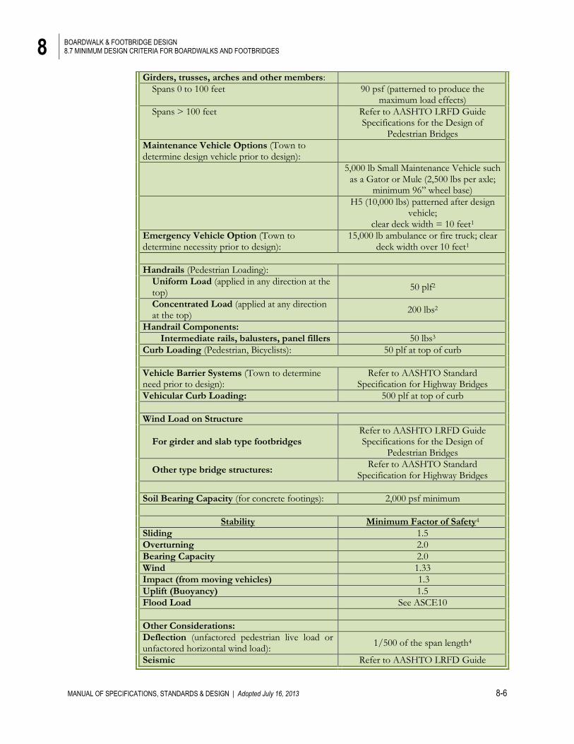
Girders, trusses, arches and other members:
Spans 0 to 100 feet 90 psf (patterned to produce the maximum load effects)
Spans > 100 feet Refer to AASHTO LRFD Guide Specifications for the Design of
Pedestrian Bridges
Maintenance Vehicle Options (Town to determine design vehicle prior to design):
5,000 lb Small Maintenance Vehicle such
as a Gator or Mule (2,500 lbs per axle; minimum 96” wheel base)
H5 (10,000 lbs) patterned after design
vehicle; clear deck width = 10 feet1
Emergency Vehicle Option (Town to determine necessity prior to design):
15,000 lb ambulance or fire truck; clear deck width over 10 feet1
Handrails (Pedestrian Loading):
Uniform Load (applied in any direction at the top)
50 plf2
Concentrated Load (applied at any direction at the top)
200 lbs2
Handrail Components:
Intermediate rails, balusters, panel fillers 50 lbs3
Curb Loading (Pedestrian, Bicyclists): 50 plf at top of curb
Vehicle Barrier Systems (Town to determine need prior to design):
Refer to AASHTO Standard Specification for Highway Bridges
Vehicular Curb Loading: 500 plf at top of curb
Wind Load on Structure
For girder and slab type footbridges Refer to AASHTO LRFD Guide Specifications for the Design of
Pedestrian Bridges
Other type bridge structures: Refer to AASHTO Standard
Specification for Highway Bridges
Soil Bearing Capacity (for concrete footings): 2,000 psf minimum
Stability Minimum Factor of Safety4
Sliding 1.5
Overturning 2.0
Bearing Capacity 2.0
Wind 1.33
Impact (from moving vehicles) 1.3
Uplift (Buoyancy) 1.5
Flood Load See ASCE10
Other Considerations:
Deflection (unfactored pedestrian live load or unfactored horizontal wind load):
1/500 of the span length4
Seismic Refer to AASHTO LRFD Guide
8 BOARDWALK & FOOTBRIDGE DESIGN 8.7 MINIMUM DESIGN CRITERIA FOR BOARDWALKS AND FOOTBRIDGES
MANUAL OF SPECIFICATIONS, STANDARDS & DESIGN | Adopted July 16, 2013 8-7
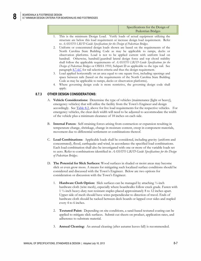
Specifications for the Design of Pedestrian Bridges
1. This is the minimum Design Load. Verify loads of actual equipment utilizing the structure are below this load requirement or increase design load requirement. Refer to AASHTO LRFD Guide Specifications for the Design of Pedestrian Bridges.
2. Uniform or concentrated design loads shown are based on the requirements of the North Carolina State Building Code as may be applicable to ramps, decks or observation platforms. Load is not to be applied current with uniform load on handrail. Otherwise, handrail/guardrail lateral design force and top chord stability shall follow the applicable requirements of AASHTO LRFD Guide Specifications for the Design of Pedestrian Bridges or OSHA 1910, Subpart D as applicable to the type rail. See paragraph 8.7.4.C for rail selection criteria and thus the design requirement.
3. Load applied horizontally on an area equal to one square foot, including openings and space between rails (based on the requirements of the North Carolina State Building Code as may be applicable to ramps, decks or observation platforms).
4. Where governing design code is more restrictive, the governing design code shall apply.
8.7.3 OTHER DESIGN CONSIDERATIONS:
A. Vehicle Considerations: Determine the type of vehicles (maintenance [light or heavy], emergency vehicles) that will utilize the facility from the Town’s Engineer and design accordingly. See Table 8.2, above for live load requirements for the respective vehicles. For emergency vehicles, the clear deck width will need to be adjusted to accommodate the width of the vehicle plus a minimum clearance of 18 inches on each side.
B. Internal Forces: Self-straining forces arising from contraction or expansion resulting in
temperature change, shrinkage, change in moisture content, creep in component materials, movement due to differential settlement or combinations thereof.
C. Load Combinations: Applicable loads shall be considered, including gravity (uniform and concentrated), flood, earthquake and wind, in accordance the specified load combinations. Each load combination shall also be investigated with one or more of the variable loads set to zero. Refer to combinations identified in AASHTO LRFD Guide Specifications for the Design of Pedestrian Bridges.
D. The Potential for Slick Surfaces: Wood surfaces in shaded or moist areas may become
slick or even grow moss. A means for mitigating such localized surface conditions should be considered and discussed with the Town’s Engineer. Below are two options for consideration or discussion with the Town’s Engineer.
1. Hardware Cloth Option: Slick surfaces can be managed by attaching ½-inch
hardware cloth (wire mesh), especially where boardwalks follow creek grade. Fasten with 1 ½-inch heavy-duty rust resistant staples placed approximately 8 to 12 inches apart. Upper side of mesh should have wires perpendicular to direction of travel. Ends of hardware cloth should be tucked between deck boards or lapped over sides and stapled every 4 to 6 inches.
2. Textured Paint: Depending on site conditions, a sand-based textured coating can be applied to mitigate slick surfaces. Submit cut sheets on product, application rates, and adherence to substrate material.
3. Annual Cleaning: An annual cleaning (after autumn leaves fall) is recommended.
8 BOARDWALK & FOOTBRIDGE DESIGN 8.7 MINIMUM DESIGN CRITERIA FOR BOARDWALKS AND FOOTBRIDGES
MANUAL OF SPECIFICATIONS, STANDARDS & DESIGN | Adopted July 16, 2013 8-8
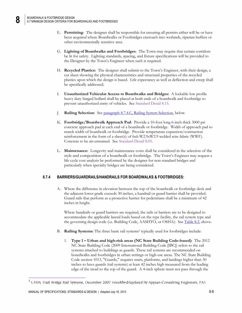
E. Permitting: The designer shall be responsible for ensuring all permits either will be or have been acquired where Boardwalks or Footbridges encroach into wetlands, riparian buffers or other environmentally sensitive area.
G. Lighting of Boardwalks and Footbridges: The Town may require that certain corridors
be lit for safety. Lighting standards, spacing, and fixture specifications will be provided to the Designer by the Town’s Engineer when such is required.
H. Recycled Plastics: The designer shall submit to the Town’s Engineer, with their design, a cut sheet showing the physical characteristics and structural properties of the recycled plastics upon which the design is based. Life expectancy as well as deflection and creep shall be specifically addressed.
I. Unauthorized Vehicular Access to Boardwalks and Bridges: A lockable low profile
heavy duty hinged bollard shall be placed at both ends of a boardwalk and footbridge to prevent unauthorized entry of vehicles. See Standard Detail 8.15.
J. Railing Selection: See paragraph 8.7.4.C, Railing System Selection, below. K. Footbridge/Boardwalk Approach Pad: Provide a 10-foot long 6-inch thick 3000 psi
concrete approach pad at each end of a boardwalk or footbridge. Width of approach pad to match width of boardwalk or footbridge. Provide temperature expansion/contraction reinforcement in the form of a sheet(s) of 6x6-W2.9xW2.9 welded wire fabric (WWF). Concrete to be air-entrained. See Standard Detail 8.05.
L. Maintenance: Longevity and maintenance costs shall be considered in the selection of the style and composition of a boardwalk or footbridge. The Town’s Engineer may request a
life cycle cost analysis be performed by the designer for non-standard bridges and particularly when specialty bridges are being considered.
8.7.4 BARRIERS/GUARDRAILS/HANDRAILS FOR BOARDWALKS & FOOTBRIDGES:
A. Where the difference in elevation between the top of the boardwalk or footbridge deck and
the adjacent lower grade exceeds 30 inches, a handrail or guard barrier shall be provided. Guard rails that perform as a protective barrier for pedestrians shall be a minimum of 42 inches in height.
Where handrails or guard barriers are required, the rails or barriers are to be designed to accommodate the applicable lateral loads based on the type facility, the rail system type and the governing design code (i.e. Building Code, AASHTO, or OSHA): See Table 8.2, above.
B. Railing Systems: The three basic rail systems1 typically used for footbridges include:
1. Type 1 – Urban and high-risk areas (NC State Building Code-based): The 2012 NC State Building Code (2009 International Building Code [IBC]) refers to the rail systems attached to buildings as guards. These rail systems are recommended on boardwalks and footbridges in urban settings or high-use areas. The NC State Building Code section 1013, "Guards," requires stairs, platforms, and landings higher than 30 inches to have guards (rail systems) at least 42 inches high measured from the leading edge of the tread to the top of the guard. A 4-inch sphere must not pass through the
1
8 BOARDWALK & FOOTBRIDGE DESIGN 8.7 MINIMUM DESIGN CRITERIA FOR BOARDWALKS AND FOOTBRIDGES
MANUAL OF SPECIFICATIONS, STANDARDS & DESIGN | Adopted July 16, 2013 8-9
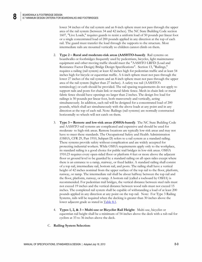
lower 34 inches of the rail system and an 8-inch sphere must not pass through the upper area of the rail system (between 34 and 42 inches). The NC State Building Code section 1607, "Live Loads," requires guards to resist a uniform load of 50 pounds per linear foot or a single concentrated load of 200 pounds applied in any direction at the top of each rail. The guard must transfer the load through the supports to the structure. Most intermediate rails are mounted vertically so children cannot climb on them.
2. Type 2 – Rural and moderate-risk areas (AASHTO-based): Rail systems on
boardwalks or footbridges frequently used by pedestrians, bicycles, light maintenance equipment and other moving traffic should meet the "AASHTO LRFD (Load and Resistance Factor Design) Bridge Design Specifications". Section 13, "Railings," requires a railing (rail system) at least 42 inches high for pedestrian traffic and at least 54 inches high for bicycle or equestrian traffic. A 6-inch sphere must not pass through the lower 27 inches of the rail system and an 8-inch sphere must not pass through the upper area of the rail system (higher than 27 inches). A safety toe rail (AASHTO's terminology) or curb should be provided. The rail spacing requirements do not apply to support rails and posts for chain link or metal fabric fence. Mesh in chain link or metal fabric fence should have openings no larger than 2 inches. The design live load for railings is 50 pounds per linear foot, both transversely and vertically, acting simultaneously. In addition, each rail will be designed for a concentrated load of 200 pounds, which shall act simultaneously with the above loads at any point and in any direction at the top of each rail. Note: Railings (rail systems) are normally constructed horizontally so wheels will not catch on them.
3. Type 3 – Remote and low-risk areas (OSHA-based): The NC State Building Code
and AASHTO rail systems are complicated and expensive and should be used for moderate- to high-risk areas. Remote locations are typically low-risk areas and may not have to meet these standards. The Occupational Safety and Health Administration (OSHA, CFR 29, Part 1910, Subpart D) refers to a rail system as a standard railing. These systems provide safety without complication and are widely accepted for protecting industrial workers. While OSHA requirements apply only to the workplace, its standard railing is a good choice for public trail bridges in low-risk areas. OSHA 1910.23 requires every open-sided floor or platform 4 feet or more above the adjacent floor or ground level to be guarded by a standard railing on all open sides except where there is an entrance to a ramp, stairway, or fixed ladder. A standard railing shall consist of a top rail, intermediate rail, bottom rail, and posts. The railing shall have a vertical height of 42 inches nominal from the upper surface of the top rail to the floor, platform, runway, or ramp. The intermediate rail shall be about halfway between the top rail and the floor, platform, runway, or ramp. A bottom rail (called a toeboard by OSHA) is recommended. For pedestrian trail bridges, the vertical distance between steel rails must not exceed 19 inches and the vertical distance between wood rails must not exceed 15 inches. The completed rail system shall be capable of withstanding a load of at least 200 pounds applied in any direction at any point on the top rail. Note: For Type 3 Railing Systems, rails will be required when the decking is greater than 30 inches above the lower adjacent grade as stated in Table 8.1.
4. Types 1, 2, & 3 – Multi-use or Bicyclist Rail Height: Multi-use, bicyclist or
equestrian rail height shall be a minimum of 54 inches above the deck with a rub rail for cyclists at 33 to 36 inches above the deck.
C. Railing System Selection:
8 BOARDWALK & FOOTBRIDGE DESIGN 8.7 MINIMUM DESIGN CRITERIA FOR BOARDWALKS AND FOOTBRIDGES
MANUAL OF SPECIFICATIONS, STANDARDS & DESIGN | Adopted July 16, 2013 8-10
Type 1: Type 1 railings systems are to be used for boardwalks and footbridges where the vertical separation is greater than 30 inches, the conditions pose a significant fall hazard (such as overpasses or stream and river crossings) and the facility traffic is limited to pedestrian, bicycle, equestrian, and small maintenance equipment. The applicability or use of this type railing system shall be determined by the design engineer and approved by Town’s Engineer. Type 2: Type 2 railings systems are to be used for boardwalks and footbridges where the vertical separation is greater than 30 inches, the conditions pose a significant fall hazard (such as overpasses or stream and river crossings) and the facility will serve pedestrians, bicycles, equestrian, small maintenance equipment, H5 loading or larger maintenance equipment, and/or emergency equipment. If a vehicle barrier is required in addition to or as part of a pedestrian railing system by the Town’s Engineer, the barrier design shall conform to the requirements of Table 8.2. The applicability or use of this type railing system shall be determined by the design engineer and approved by Town’s Engineer. Type 3: Type 3 railing systems are to be used for boardwalks and footbridges where the vertical separation is greater than 30 inches and traffic is limited primarily to rural areas serving pedestrian, bicycle, equestrian, and small maintenance equipment. Unless otherwise necessitated by design requirements, trail type or when directed by the Town’s Engineer, Type 3 railing systems shall the standard rail type typically employed for boardwalks and footbridges.
8.7.5 FOOTBRIDGE STYLES & TYPES:
A. For the purpose of consistency, the footbridge style or type shall take the appearance of one or more of the following. For consistency, try to utilize a single style along the entire trail under design consideration unless the span dictates otherwise. Other styles and configurations will be considered by the Town’s Engineer on a case-by-case basis.
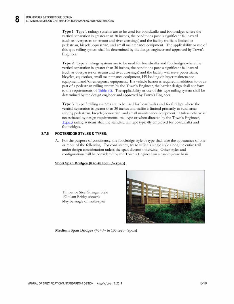
Short Span Bridges (8 to 40 feet+/- span)
Timber or Steel Stringer Style (Glulam Bridge shown)
May be single or multi-span
Medium Span Bridges (40+/- to 100 feet+ Span)
8 BOARDWALK & FOOTBRIDGE DESIGN 8.8 MATERIALS:
MANUAL OF SPECIFICATIONS, STANDARDS & DESIGN | Adopted July 16, 2013 8-11
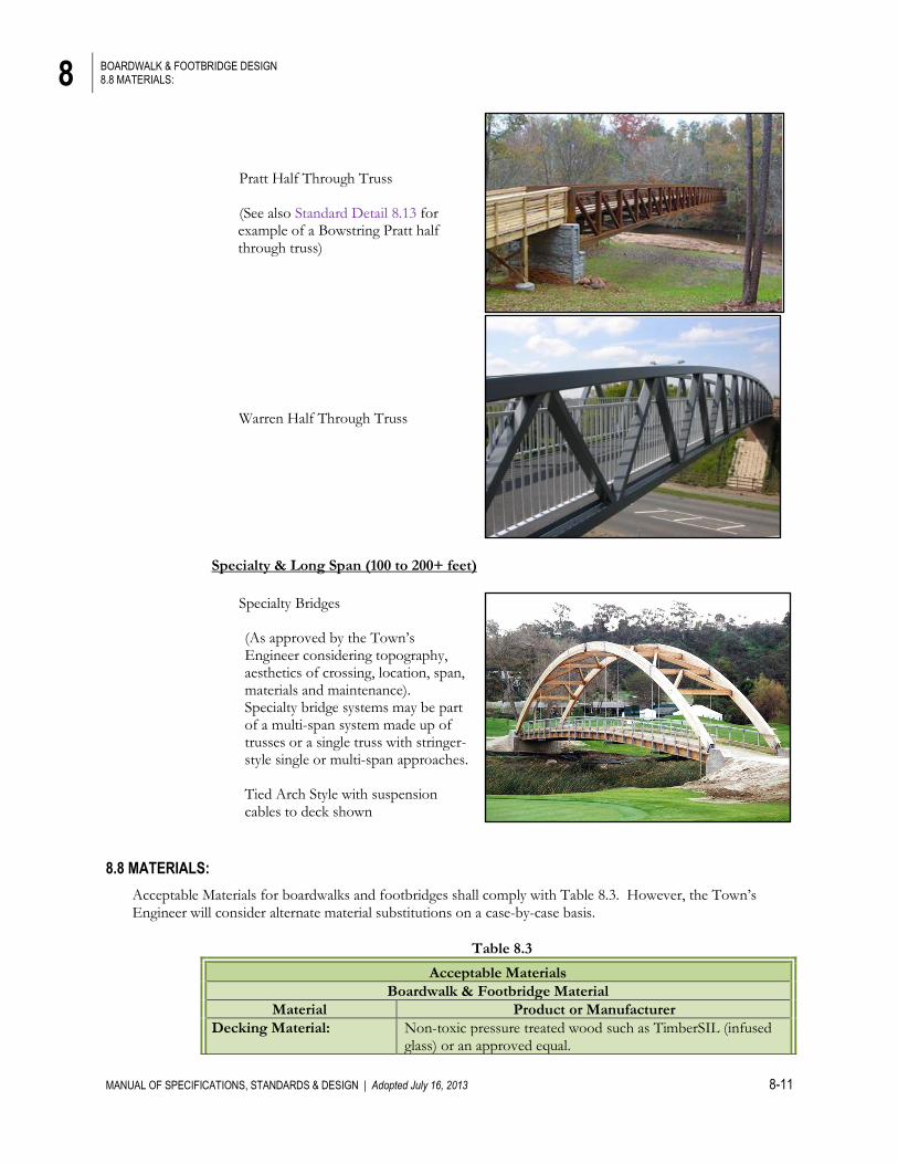
Pratt Half Through Truss (See also Standard Detail 8.13 for
example of a Bowstring Pratt half through truss)
Warren Half Through Truss
Specialty & Long Span (100 to 200+ feet)
Specialty Bridges
(As approved by the Town’s Engineer considering topography, aesthetics of crossing, location, span, materials and maintenance). Specialty bridge systems may be part of a multi-span system made up of trusses or a single truss with stringer-style single or multi-span approaches.
Tied Arch Style with suspension cables to deck shown
8.8 MATERIALS:
Acceptable Materials for boardwalks and footbridges shall comply with Table 8.3. However, the Town’s Engineer will consider alternate material substitutions on a case-by-case basis.
Table 8.3
Acceptable Materials
Boardwalk & Footbridge Material
Material Product or Manufacturer
Decking Material: Non-toxic pressure treated wood such as TimberSIL (infused glass) or an approved equal.
8 BOARDWALK & FOOTBRIDGE DESIGN 8.8 MATERIALS:
MANUAL OF SPECIFICATIONS, STANDARDS & DESIGN | Adopted July 16, 2013 8-12
Naturally rot resistant (such as Red Cedar)
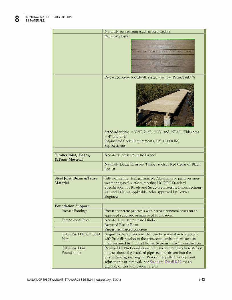
Recycled plastic
Precast concrete boardwalk system (such as PermaTrakTM) Standard widths = 3’-9”, 7’-6”, 11’-3” and 15”-4”. Thickness = 4” and 5 ½” Engineered Code Requirements: H5 (10,000 lbs). Slip Resistant
Timber Joist, Beam, &Truss Material
Non-toxic pressure treated wood
Naturally Decay Resistant Timber such as Red Cedar or Black Locust
Steel Joist, Beam &Truss Material
Self-weathering steel, galvanized, Aluminum or paint on non-weathering steel surfaces meeting NCDOT Standard Specification for Roads and Structures, latest revision, Sections 442 and 1180, as applicable; color approved by Town’s Engineer.
Foundation Support:
Precast Footings Precast concrete pedestals with precast concrete bases on an approved subgrade or improved foundation.
Dimensional Piles: Non-toxic pressure treated timber
Recycled Plastic Posts
Precast reinforced concrete
Galvanized Helical Steel Piers
Augur-like helical anchors that can be screwed in to the soils with little disruption to the ecosystem environment such as manufactured by Hubbell Power Systems – Civil Construction.
Galvanized Pin Foundations
Patented by Pin Foundations, Inc., the system uses 4- to 8-foot long sections of galvanized pipe sections driven into the ground at diagonal angles. Pins can be pulled up to permit adjustments or removal. See Standard Detail 8.12 for an example of this foundation system.
8 BOARDWALK & FOOTBRIDGE DESIGN 8.9 POSTING A LOAD RATING
MANUAL OF SPECIFICATIONS, STANDARDS & DESIGN | Adopted July 16, 2013 8-13
Concrete Foundation Precast Concrete abutments (slabs, tees, or special cast shapes)
Cast-in-place reinforced concrete (rubbed or textured finish or clad in natural stone veneer)
Reinforced concrete masonry block (clad with natural stone veneer if visible to public)
8.9 POSTING A LOAD RATING
Each approach of each section of boardwalk or footbridges shall be posted with sign indicating the structures safe load rating. Signs shall match the greenway system signage.
8.10 OVERPASSES:
A. Where footbridges are designed as overpasses (over existing roadways), safety should be the primary consideration.
B. A signature bridge should be considered in areas of high visibility, such as over major
roadways. This may include special LED lighting elements for nighttime enhancement/visibility.
C. Aesthetically pleasing galvanized steel debris netting (or other approved style and color) shall
be provided on both sides and up over the top to at least 8 feet above the decking. Mesh shall be minimum 2x2.
D. For shared-use facilities, a minimum width of 14 feet is recommended.
8.11 UNDERPASSES:
A. An underpass is typically a crossing constructed beneath a new or existing roadway. Underpasses work best with favorable topography when they are open and accessible, and exhibit a sense of safety.
B. An underpass can also be a trail crossing beneath an existing overhead roadway bridge where such structures cross streams or rivers. The underpass must be large enough to accommodate trail users and meet the prescribed clearances. In some cases, a protective housing, such as a multi-plate arch or other similar structure, can be placed beneath the overpass to protect trail users from falling objects (such as railroad ballast, etc.).
C. Proper drainage must be established to avoid pooling of stormwater; however, some
underpasses can be designed to flood periodically (after significant rainfall). D. Ideal vertical clearance of the underpass is 12 feet but, with the approval of the Town’s
Engineer, may be reduced to no less than 10 feet. E. The width of an underpass shall be at least 12 feet.
F. Headwalls and wingwalls are required on both ends. G. Longitudinal grade shall be no less than 1%. H. Illuminance: Underpasses should have a daytime illuminance of 10 foot-candles minimum
achievable through artificial and/or natural light provided through an open gap to the sky between two sets of highway lanes. Nighttime illuminance level: 4 foot-candles.

8 BOARDWALK & FOOTBRIDGE DESIGN 8.12 REFERENCES
MANUAL OF SPECIFICATIONS, STANDARDS & DESIGN | Adopted July 16, 2013 8-14
I. See Standard Detail 8.14.
8.12 REFERENCES
1. 2012 NC State Building Code (2009 IBC w/ NC Amendments) 2. American Association of State Highway and Transportation Officials (AASHTO),
Standard Specifications for Highway Bridges, Washington DC, 16th Edition, 1996 with 1997 and 1998 Interims.
3. American Association of State Highway and Transportation Officials (AASHTO),
AASHTO LRFD (Load and Resistance Factor Design) Guide Specifications for the Design of Pedestrian Bridges, 2nd Edition, w/ 2015 Interim Revisions.
4. Photo Credit: “Riverwalk” photo image showing isosceles corners on footbridge
courtesy of Cline Design Associates, PA, Raleigh, NC, 919.833.6413. 5. USDA Trail Bridge Rail Systems, December 2007, http://www.fs.fed.us/t-
d/pubs/htmlpubs/htm07232329/ 6. OSHA Part 1910 Subpart D, Waling-Working Surfaces 1910.23, Guarding Floor and
Wall Openings and Holes, https://www.osha.gov/pls/oshaweb/owadisp.show_document?p_table=STANDARDS&p_id=9715
8 BOARDWALK & FOOTBRIDGE DESIGN 8.13 APPENDIX OF TABLES
MANUAL OF SPECIFICATIONS, STANDARDS & DESIGN | Adopted July 16, 2013 8-15
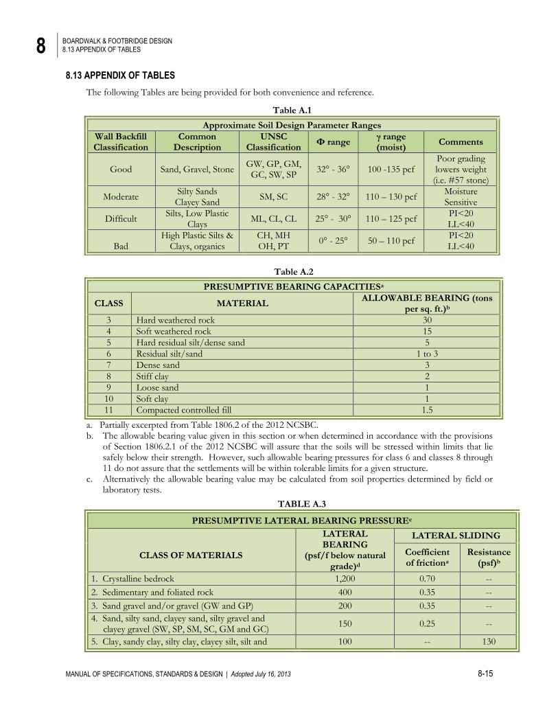
8.13 APPENDIX OF TABLES
The following Tables are being provided for both convenience and reference.
Table A.2
PRESUMPTIVE BEARING CAPACITIESa
CLASS MATERIAL ALLOWABLE BEARING (tons
per sq. ft.)b
3 Hard weathered rock 30
4 Soft weathered rock 15
5 Hard residual silt/dense sand 5
6 Residual silt/sand 1 to 3
7 Dense sand 3
8 Stiff clay 2
9 Loose sand 1
10 Soft clay 1
11 Compacted controlled fill 1.5
a. Partially excerpted from Table 1806.2 of the 2012 NCSBC. b. The allowable bearing value given in this section or when determined in accordance with the provisions
of Section 1806.2.1 of the 2012 NCSBC will assure that the soils will be stressed within limits that lie safely below their strength. However, such allowable bearing pressures for class 6 and classes 8 through 11 do not assure that the settlements will be within tolerable limits for a given structure.
c. Alternatively the allowable bearing value may be calculated from soil properties determined by field or laboratory tests.
TABLE A.3
PRESUMPTIVE LATERAL BEARING PRESSUREe
CLASS OF MATERIALS
LATERAL BEARING
(psf/f below natural grade)d
LATERAL SLIDING
Coefficient of frictiona
Resistance (psf)b
1. Crystalline bedrock 1,200 0.70 --
2. Sedimentary and foliated rock 400 0.35 --
3. Sand gravel and/or gravel (GW and GP) 200 0.35 --
4. Sand, silty sand, clayey sand, silty gravel and clayey gravel (SW, SP, SM, SC, GM and GC)
150 0.25 --
5. Clay, sandy clay, silty clay, clayey silt, silt and 100 -- 130
Table A.1
Approximate Soil Design Parameter Ranges
Wall Backfill Classification
Common Description
UNSC Classification
Φ range γ range (moist)
Comments
Good Sand, Gravel, Stone GW, GP, GM, GC, SW, SP
32° - 36° 100 -135 pcf Poor grading lowers weight
(i.e. #57 stone)
Moderate Silty Sands Clayey Sand
SM, SC 28° - 32° 110 – 130 pcf Moisture Sensitive
Difficult Silts, Low Plastic
Clays ML, CL, CL 25° - 30° 110 – 125 pcf
PI<20 LL<40
Bad
High Plastic Silts & Clays, organics
CH, MH OH, PT
0° - 25° 50 – 110 pcf PI<20 LL<40
8 BOARDWALK & FOOTBRIDGE DESIGN 8.13 APPENDIX OF TABLES
MANUAL OF SPECIFICATIONS, STANDARDS & DESIGN | Adopted July 16, 2013 8-16
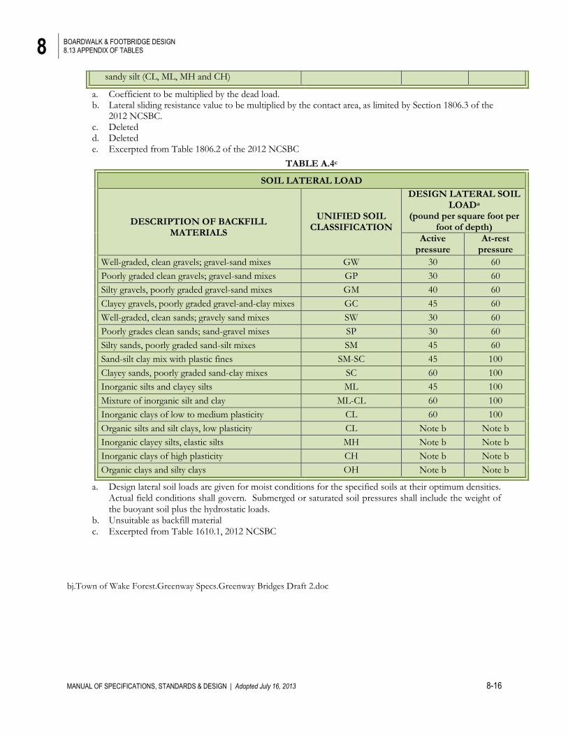
sandy silt (CL, ML, MH and CH)
a. Coefficient to be multiplied by the dead load. b. Lateral sliding resistance value to be multiplied by the contact area, as limited by Section 1806.3 of the
2012 NCSBC. c. Deleted d. Deleted e. Excerpted from Table 1806.2 of the 2012 NCSBC
TABLE A.4c
SOIL LATERAL LOAD
DESCRIPTION OF BACKFILL
MATERIALS
UNIFIED SOIL CLASSIFICATION
DESIGN LATERAL SOIL LOADa
(pound per square foot per foot of depth)
Active pressure
At-rest pressure
Well-graded, clean gravels; gravel-sand mixes GW 30 60
Poorly graded clean gravels; gravel-sand mixes GP 30 60
Silty gravels, poorly graded gravel-sand mixes GM 40 60
Clayey gravels, poorly graded gravel-and-clay mixes GC 45 60
Well-graded, clean sands; gravely sand mixes SW 30 60
Poorly grades clean sands; sand-gravel mixes SP 30 60
Silty sands, poorly graded sand-silt mixes SM 45 60
Sand-silt clay mix with plastic fines SM-SC 45 100
Clayey sands, poorly graded sand-clay mixes SC 60 100
Inorganic silts and clayey silts ML 45 100
Mixture of inorganic silt and clay ML-CL 60 100
Inorganic clays of low to medium plasticity CL 60 100
Organic silts and silt clays, low plasticity CL Note b Note b
Inorganic clayey silts, elastic silts MH Note b Note b
Inorganic clays of high plasticity CH Note b Note b
Organic clays and silty clays OH Note b Note b
a. Design lateral soil loads are given for moist conditions for the specified soils at their optimum densities. Actual field conditions shall govern. Submerged or saturated soil pressures shall include the weight of the buoyant soil plus the hydrostatic loads.
b. Unsuitable as backfill material c. Excerpted from Table 1610.1, 2012 NCSBC
bj.Town of Wake Forest.Greenway Specs.Greenway Bridges Draft 2.doc