Stormwater C.3 Guidebook - City of Milpitas · The Guidebook, other design resources, and ......
91
Determine if C.3 and HMP Requirements Must be Met Project Classifications♦ Added or Replaced Impervious Surface Threshold “Deemed Complete” C.3 Required HMP Required♣ On or after October 15, 2003 √ Group 1 1 acre (43,560 square feet) or more On or after October 6, 2005 √ √ Group 2A 10,000 square feet or more for projects of concern On or after October 6, 2005 √ Group 2B 10,000 square feet or more On or after August 15, 2006 √ HMP = Hydromodification Management Plan ♦ Group definitions are shown in Chapter 1 and in the Glossary. ♣ Refer to FIGURE 8-1 on page 67 to determine if you are required to submit a Hydromodification Management Plan (HMP). City of Milpitas 455 East Calaveras Boulevard Milpitas, CA 95035 www.ci.milpitas.ca.gov 3 rd Edition – October 6, 2005 Stormwater C.3 Guidebook Guidance for Implementing the Stormwater Treatment Requirements
Transcript of Stormwater C.3 Guidebook - City of Milpitas · The Guidebook, other design resources, and ......
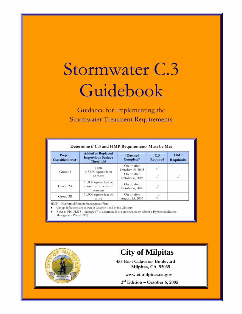
Determine if C.3 and HMP Requirements Must be Met
Project Classifications♦
Added or Replaced Impervious Surface
Threshold
“Deemed Complete”
C.3 Required
HMP Required♣
On or after October 15, 2003 √
Group 1 1 acre
(43,560 square feet) or more On or after
October 6, 2005 √ √
Group 2A 10,000 square feet or more for projects of
concern
On or after October 6, 2005 √
Group 2B 10,000 square feet or more
On or after August 15, 2006 √
HMP = Hydromodification Management Plan ♦ Group definitions are shown in Chapter 1 and in the Glossary. ♣ Refer to FIGURE 8-1 on page 67 to determine if you are required to submit a Hydromodification
Management Plan (HMP).
City of Milpitas 455 East Calaveras Boulevard
Milpitas, CA 95035
www.ci.milpitas.ca.gov
3rd Edition – October 6, 2005
Stormwater C.3 Guidebook
Guidance for Implementing the Stormwater Treatment Requirements


T A B L E O F C O N T E N T S
i
TABLE OF CONTENTS
Appendices iv
List of Tables & Figures v
“C.3” Fact Sheet, Pages 1-4
How to Use this Guidebook 1
1 Overview 3 1.1 State and Federal Regulatory Perspective 3 1.2 Local Development Review Perspective 4
► DOES C.3 APPLY TO YOUR PROJECT? 4 ► DEVELOPMENT REVIEW PROCESS 6
1.3 Planning and Design Perspective 9 1.4 Environmental Benefit Perspective 10
2 Stormwater Concepts 13 2.1 Maximum Extent Practicable 13 2.2 Best Management Practices 14 2.3 Imperviousness 15 2.4 Design Storm 16
3 Preparing Your Stormwater Control Plan 17 ► OBJECTIVES. 17 ► CONTENTS. 17 ► STEP BY STEP 17
3.1 Step 1: Assemble Needed Information 18 3.2 Step 2: Identify Constraints & Opportunities 19 3.3 Step 3: Design to Minimize Imperviousness 19
► CLUSTER DEVELOPMENT 19 ► OPTIMIZE THE SITE LAYOUT 20 ► MINIMIZE DIRECTLY CONNECTED IMPERVIOUS AREA 20 ► DETAIN AND RETAIN RUNOFF THROUGHOUT THE SITE 21 ► DOCUMENT YOUR SITE DESIGN MEASURES 21
3.4 Step 4: Locate and Select Treatment BMPs 21 ► GUIDANCE FOR SELECTING BMPS 22 ► LOCATING TREATMENT BMPS ON YOUR SITE 23
3.5 Step 5: Perform Preliminary Design of BMPs 24 3.6 Step 6. Specify Source Control BMPs 24
► IDENTIFY POLLUTANT SOURCES 24
C I T Y O F M I L P I T A S S T O R M W A T E R C . 3 G U I D E B O O K
ii
► IDENTIFY PERMANENT SOURCE CONTROL MEASURES 25 ► IDENTIFY OPERATIONAL SOURCE CONTROL BMPS 25 ► IDENTIFY PESTICIDE REDUCTION MEASURES 25
3.7 Step 7: Integrate With Other Preliminary Drawings. 26 3.8 Step 8: Permitting & Code Compliance Issues. 27 3.9 Step 9: Identify BMP Maintenance Needs 27
► BMP MAINTENANCE INFORMATION IN YOUR STORMWATER CONTROL PLAN 28 ► OUTREACH ACTIVITIES FOR PESTICIDE REDUCTION 28
3.10 Step 10: Stormwater Control Plan & Report 29 ► CONSTRUCTION PLAN C.3 CHECKLIST 29 ► C.3 DATA FORM 30 ► HYDROMODIFICATION MANAGEMENT PLAN (HMP) FORM 30 ► WAIVER FORM 30 ► ALTERNATIVE COMPLIANCE FORM 30 ► CERTIFICATION 30 ► EXAMPLE STORMWATER CONTROL PLANS 30 ► SAMPLE OUTLINE AND CONTENTS 31
4 Stormwater Control & CEQA 33 4.1 CEQA and Water Quality Regulations 33 4.2 Thresholds of Significance 34
► INCORPORATING MITIGATION MEASURES 34 ► STORMWATER IMPACTS AND THE CEQA PROCESS 34
5 Technical Requirements 37 5.1 Part 1: Stormwater Control Technical Criteria 37
► LIMITS ON THE USE OF INFILTRATION 38 ► NUMERIC CRITERIA 38 ► VOLUME-BASED NUMERIC CRITERIA 38 ► FLOW-BASED CRITERIA 40
5.2 Part 2: BMP Design and Documentation 41 ► RECOMMENDED PROCEDURE FOR DESIGN AND DOCUMENTATION 42 ► SELECTING AND DOCUMENTING SELF-RETAINING AREAS AND BMPS 42 ► ROUTE RUNOFF TO INTEGRATED/DISTRIBUTED BMPS 44 ► SIZING CONVENTIONAL BMPS IF NECESSARY 44
5.3 Part 3: Design Help 46 ► SITE DESIGN AND SELF-RETAINING AREAS 46 ► GALLERY OF INTEGRATED/DISTRIBUTED BMPS 46 ► DESIGN OF CONVENTIONAL BMPS 47 ► VECTOR CONTROL AND OTHER CONSIDERATIONS FOR BMP DESIGN 47
5.4 BMP Gallery 48 ► LANDSCAPE SWALE 49 ► VEGETATED FILTER 50 ► STORMWATER PLANTER 51 ► SAND FILTER 52 ► LANDSCAPE INFILTRATION/BIORETENTION 53 ► BIORETENTION 54
6 BMP Maintenance 55
T A B L E O F C O N T E N T S
iii
6.1 Step 1: Responsibility for BMP Maintenance 56 6.2 Step 2: General Maintenance Requirements 57
► VEGETATED FILTERS, SWALES, AND BIORETENTION AREAS 57 ► PLANTER BOXES 57 ► SAND FILTERS 58 ► WET, EXTENDED WET DETENTION, AND DRY DETENTION PONDS 58
6.3 Step 3: Identify O&M Plan Preparer 59 6.4 Step 4: Interim Operation & Maintenance 59
► CONSTRUCTION-PHASE CONCERNS FOR STORMWATER BMPS 60 6.5 Step 5: Detailed Operation & Maintenance Plan 60 6.6 Step 6: Transfer Responsibility 61 6.7 Step 7: Operation & Maintenance Verification 61
7 Waiver and Alternative Compliance Options 63
8 Hydromodification Management Plan (HMP) 65
Abbreviations 69
Bibliography 71
Glossary 73
C I T Y O F M I L P I T A S S T O R M W A T E R C . 3 G U I D E B O O K
iv
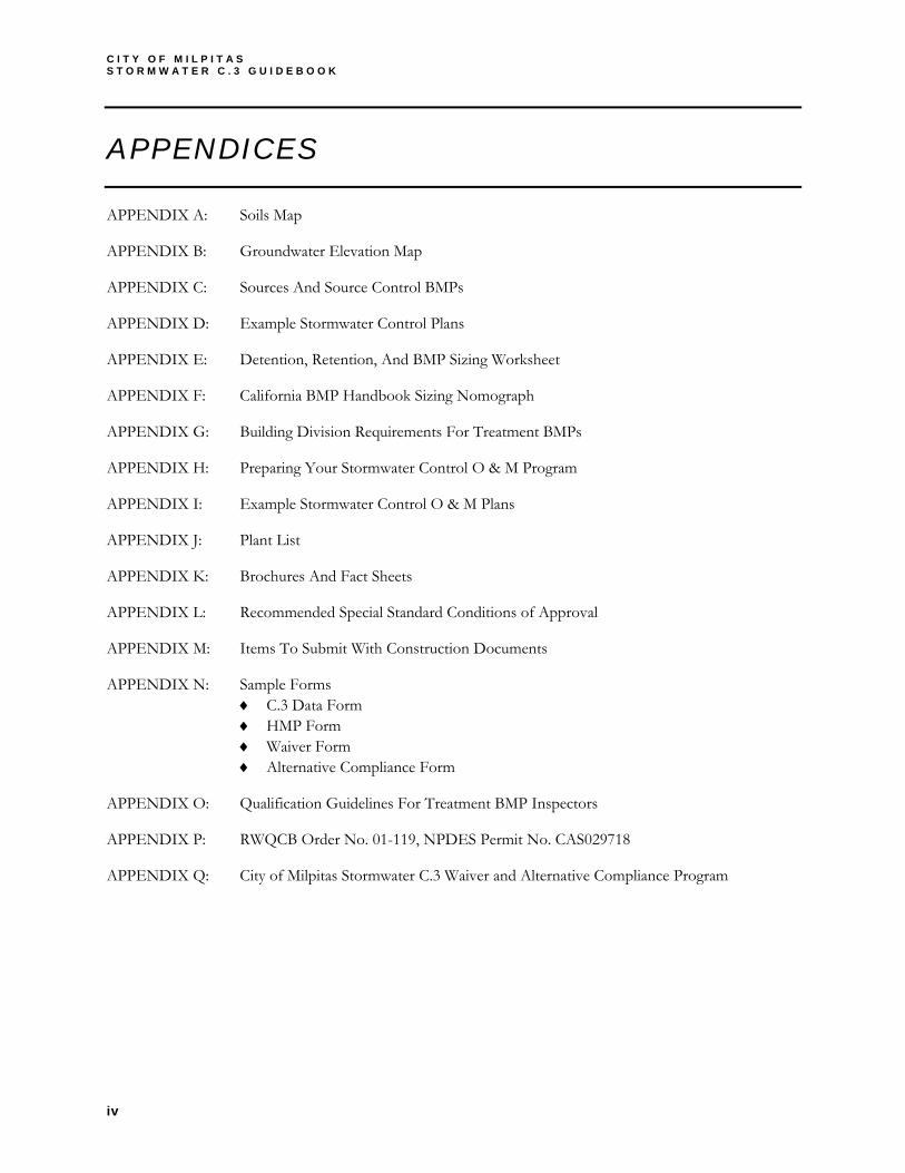
APPENDICES
APPENDIX A: Soils Map
APPENDIX B: Groundwater Elevation Map
APPENDIX C: Sources And Source Control BMPs
APPENDIX D: Example Stormwater Control Plans
APPENDIX E: Detention, Retention, And BMP Sizing Worksheet
APPENDIX F: California BMP Handbook Sizing Nomograph
APPENDIX G: Building Division Requirements For Treatment BMPs
APPENDIX H: Preparing Your Stormwater Control O & M Program
APPENDIX I: Example Stormwater Control O & M Plans
APPENDIX J: Plant List
APPENDIX K: Brochures And Fact Sheets
APPENDIX L: Recommended Special Standard Conditions of Approval
APPENDIX M: Items To Submit With Construction Documents
APPENDIX N: Sample Forms ♦ C.3 Data Form ♦ HMP Form ♦ Waiver Form ♦ Alternative Compliance Form
APPENDIX O: Qualification Guidelines For Treatment BMP Inspectors
APPENDIX P: RWQCB Order No. 01-119, NPDES Permit No. CAS029718
APPENDIX Q: City of Milpitas Stormwater C.3 Waiver and Alternative Compliance Program
T A B L E O F C O N T E N T S
v
LIST OF TABLES & FIGURES
TABLE 1-1 Project Classifications – Determining if C.3 and HMP Requirements Must be Met 5
TABLE 1-2 Required C3 Submittals to the City 5
TABLE 1-3 SWPPP vs. Stormwater Control Plan 8
TABLE 2-1 BMP Classifications 14
TABLE 3-1 Format for Permanent Source Control BMPs 25
TABLE 3-2 Format for Construction Plan C.3 Checklist 29
TABLE 3-3 Sample Outline and Contents 31
TABLE 5-1 Guidelines on the Use of Infiltration Devices 39
TABLE 5-2 Table 1, Detention, Retention, and BMP Sizing Worksheet 43
TABLE 5-3 Table 2, Detention, Retention, and BMP Sizing Worksheet 45
TABLE 6-1 Operation & Maintenance Schedule 56
FIGURE 1-1 City’s Development Review Process 7
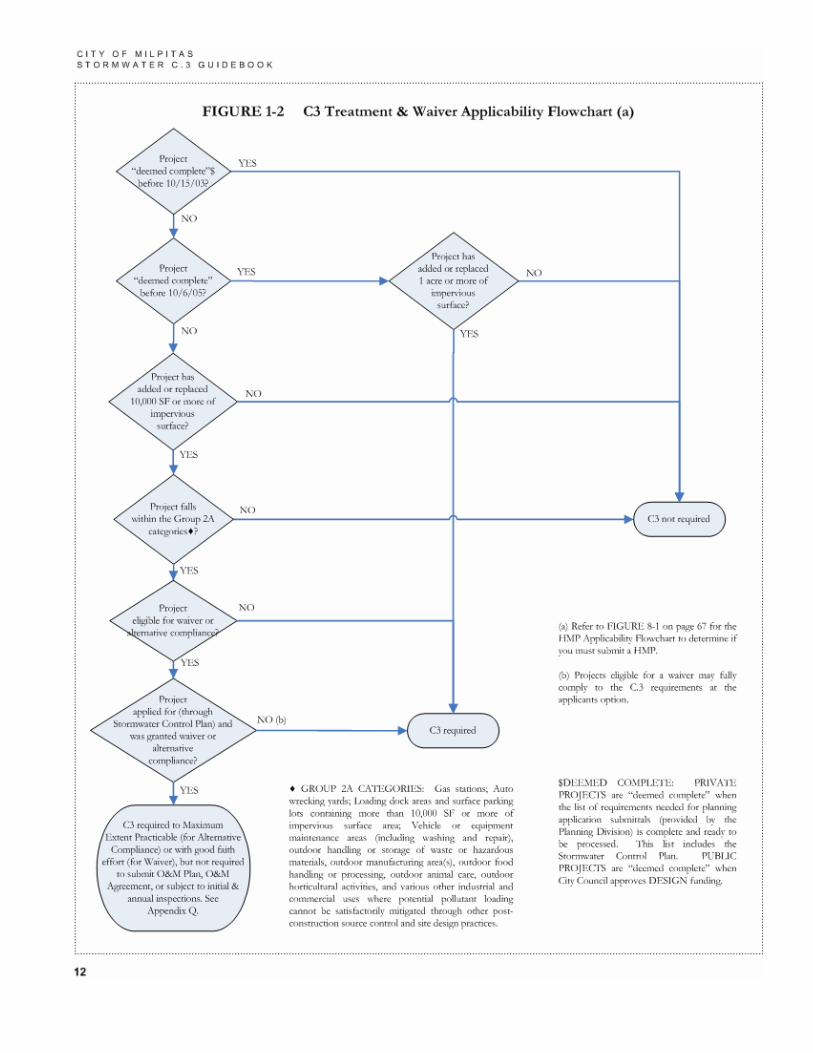
FIGURE 1-2 C3 Treatment & Waiver Applicability Flowchart 12
FIGURE 5-1 Self-Retaining Areas (Impervious vs. Pervious) 43
FIGURE 8-1 Hydromodification Management Plan (HMP) Applicability Flowchart 67


Fact Sheet 1
“C.3” Fact Sheet, Pages
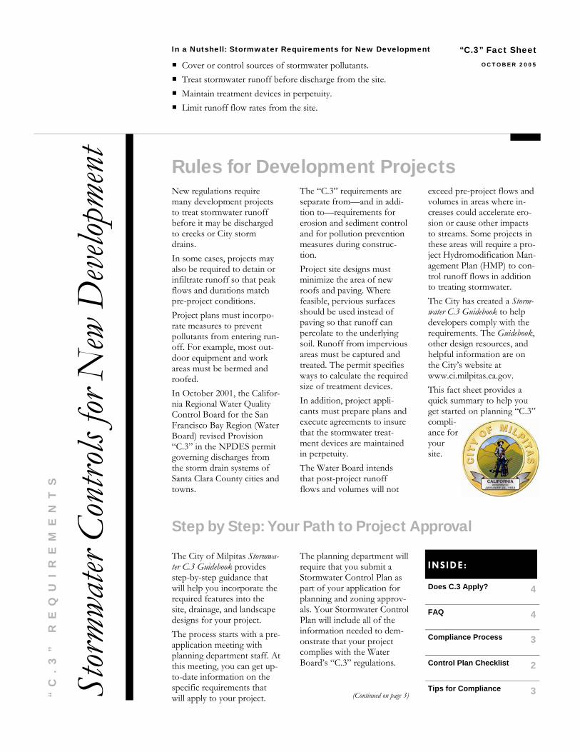
New regulations require many development projects to treat stormwater runoff before it may be discharged to creeks or City storm drains. In some cases, projects may also be required to detain or infiltrate runoff so that peak flows and durations match pre-project conditions. Project plans must incorpo-rate measures to prevent pollutants from entering run-off. For example, most out-door equipment and work areas must be bermed and roofed. In October 2001, the Califor-nia Regional Water Quality Control Board for the San Francisco Bay Region (Water Board) revised Provision “C.3” in the NPDES permit governing discharges from the storm drain systems of Santa Clara County cities and towns.
The “C.3” requirements are separate from—and in addi-tion to—requirements for erosion and sediment control and for pollution prevention measures during construc-tion. Project site designs must minimize the area of new roofs and paving. Where feasible, pervious surfaces should be used instead of paving so that runoff can percolate to the underlying soil. Runoff from impervious areas must be captured and treated. The permit specifies ways to calculate the required size of treatment devices. In addition, project appli-cants must prepare plans and execute agreements to insure that the stormwater treat-ment devices are maintained in perpetuity. The Water Board intends that post-project runoff flows and volumes will not
exceed pre-project flows and volumes in areas where in-creases could accelerate ero-sion or cause other impacts to streams. Some projects in these areas will require a pro-ject Hydromodification Man-agement Plan (HMP) to con-trol runoff flows in addition to treating stormwater. The City has created a Storm-water C.3 Guidebook to help developers comply with the requirements. The Guidebook, other design resources, and helpful information are on the City’s website at www.ci.milpitas.ca.gov. This fact sheet provides a quick summary to help you get started on planning “C.3” compli-ance for your site.
“C.3” Fact Sheet
Rules for Development Projects
OCTOBER 2005
In a Nutshell: Stormwater Requirements for New Development
Cover or control sources of stormwater pollutants. Treat stormwater runoff before discharge from the site. Maintain treatment devices in perpetuity. Limit runoff flow rates from the site.
Stor
mwat
er Co
ntro
ls for
New
Deve
lopme
nt
“C
.3
”
RE
QU
IR
EM
EN
TS
Step by Step: Your Path to Project Approval
The City of Milpitas Stormwa-ter C.3 Guidebook provides step-by-step guidance that will help you incorporate the required features into the site, drainage, and landscape designs for your project. The process starts with a pre-application meeting with planning department staff. At this meeting, you can get up-to-date information on the specific requirements that will apply to your project.
The planning department will require that you submit a Stormwater Control Plan as part of your application for planning and zoning approv-als. Your Stormwater Control Plan will include all of the information needed to dem-onstrate that your project complies with the Water Board’s “C.3” regulations.
(Continued on page 3)
Does C.3 Apply?
4
FAQ 4
Compliance Process 3
Control Plan Checklist 2
Tips for Compliance 3
INSIDE:
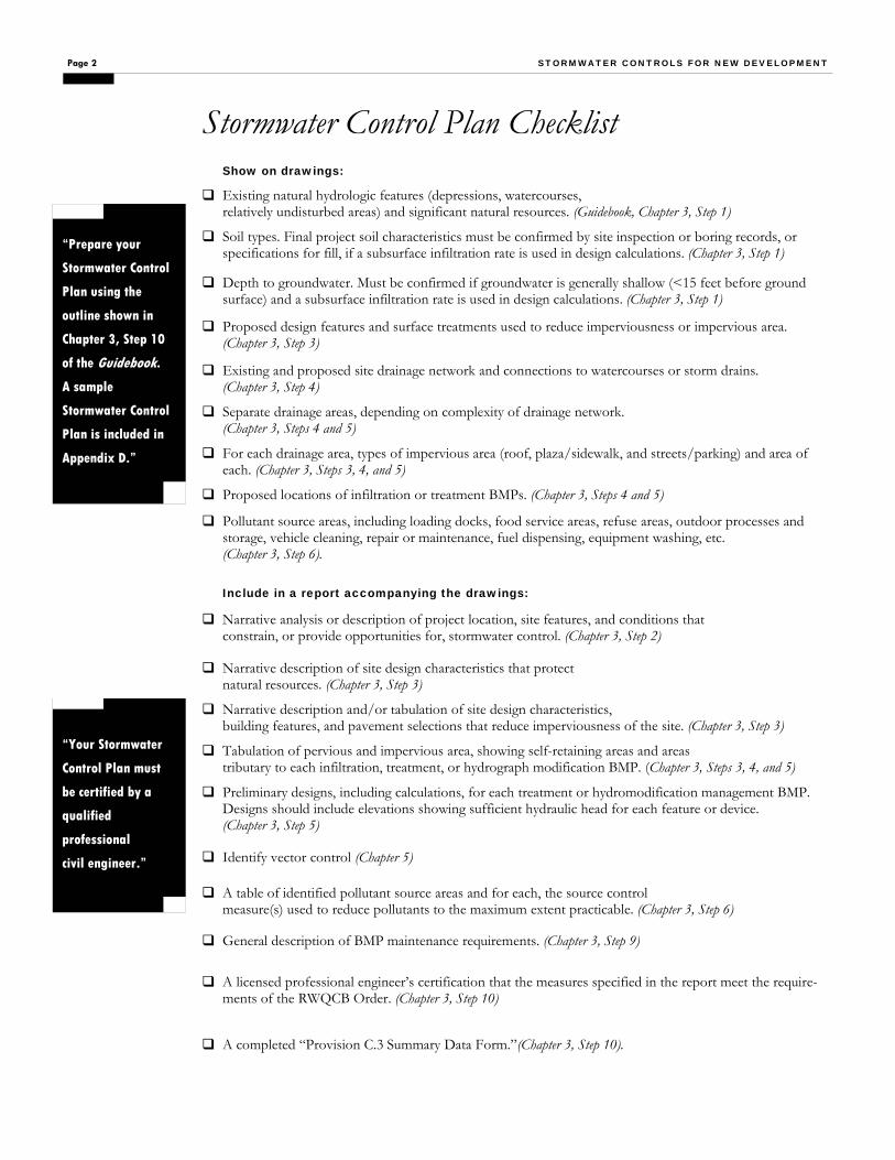
Page 2 STORMWATER CONTROLS FOR NEW DEVELOPMENT
Stormwater Control Plan Checklist Show on drawings:
Existing natural hydrologic features (depressions, watercourses, relatively undisturbed areas) and significant natural resources. (Guidebook, Chapter 3, Step 1)
Soil types. Final project soil characteristics must be confirmed by site inspection or boring records, or specifications for fill, if a subsurface infiltration rate is used in design calculations. (Chapter 3, Step 1)
Depth to groundwater. Must be confirmed if groundwater is generally shallow (<15 feet before ground surface) and a subsurface infiltration rate is used in design calculations. (Chapter 3, Step 1)
Proposed design features and surface treatments used to reduce imperviousness or impervious area. (Chapter 3, Step 3)
Existing and proposed site drainage network and connections to watercourses or storm drains. (Chapter 3, Step 4)
Separate drainage areas, depending on complexity of drainage network. (Chapter 3, Steps 4 and 5)
For each drainage area, types of impervious area (roof, plaza/sidewalk, and streets/parking) and area of each. (Chapter 3, Steps 3, 4, and 5)
Proposed locations of infiltration or treatment BMPs. (Chapter 3, Steps 4 and 5)
Pollutant source areas, including loading docks, food service areas, refuse areas, outdoor processes and storage, vehicle cleaning, repair or maintenance, fuel dispensing, equipment washing, etc. (Chapter 3, Step 6).
Include in a report accompanying the drawings:
Narrative analysis or description of project location, site features, and conditions that constrain, or provide opportunities for, stormwater control. (Chapter 3, Step 2)
Narrative description of site design characteristics that protect natural resources. (Chapter 3, Step 3)
Narrative description and/or tabulation of site design characteristics, building features, and pavement selections that reduce imperviousness of the site. (Chapter 3, Step 3)
Tabulation of pervious and impervious area, showing self-retaining areas and areas tributary to each infiltration, treatment, or hydrograph modification BMP. (Chapter 3, Steps 3, 4, and 5)
Preliminary designs, including calculations, for each treatment or hydromodification management BMP. Designs should include elevations showing sufficient hydraulic head for each feature or device. (Chapter 3, Step 5)
A table of identified pollutant source areas and for each, the source control measure(s) used to reduce pollutants to the maximum extent practicable. (Chapter 3, Step 6)
General description of BMP maintenance requirements. (Chapter 3, Step 9)
A licensed professional engineer’s certification that the measures specified in the report meet the require-ments of the RWQCB Order. (Chapter 3, Step 10)
A completed “Provision C.3 Summary Data Form.”(Chapter 3, Step 10).
Identify vector control (Chapter 5)
“Your Stormwater
Control Plan must
be certified by a
qualified
professional
civil engineer.”
“Prepare your
Stormwater Control
Plan using the
outline shown in
Chapter 3, Step 10
of the Guidebook.
A sample
Stormwater Control
Plan is included in
Appendix D.”
Your Stormwater Control Plan must be certified by a qualified professional civil engineer. City staff will use the checklist on page 2 (opposite) to deter-mine if your Stormwater Control Plan is complete. Following planning and zoning approval, you must ensure that each item in your Stormwater Control Plan is incorporated in the project construction plans. A BMP Operation and Mainte-nance Plan must be submitted to the City before the end of con-struction. The occupant or owner must verify, at least annu-ally, that the treatment and hy-dromodification management devices on-site are being main-tained according to the plan.
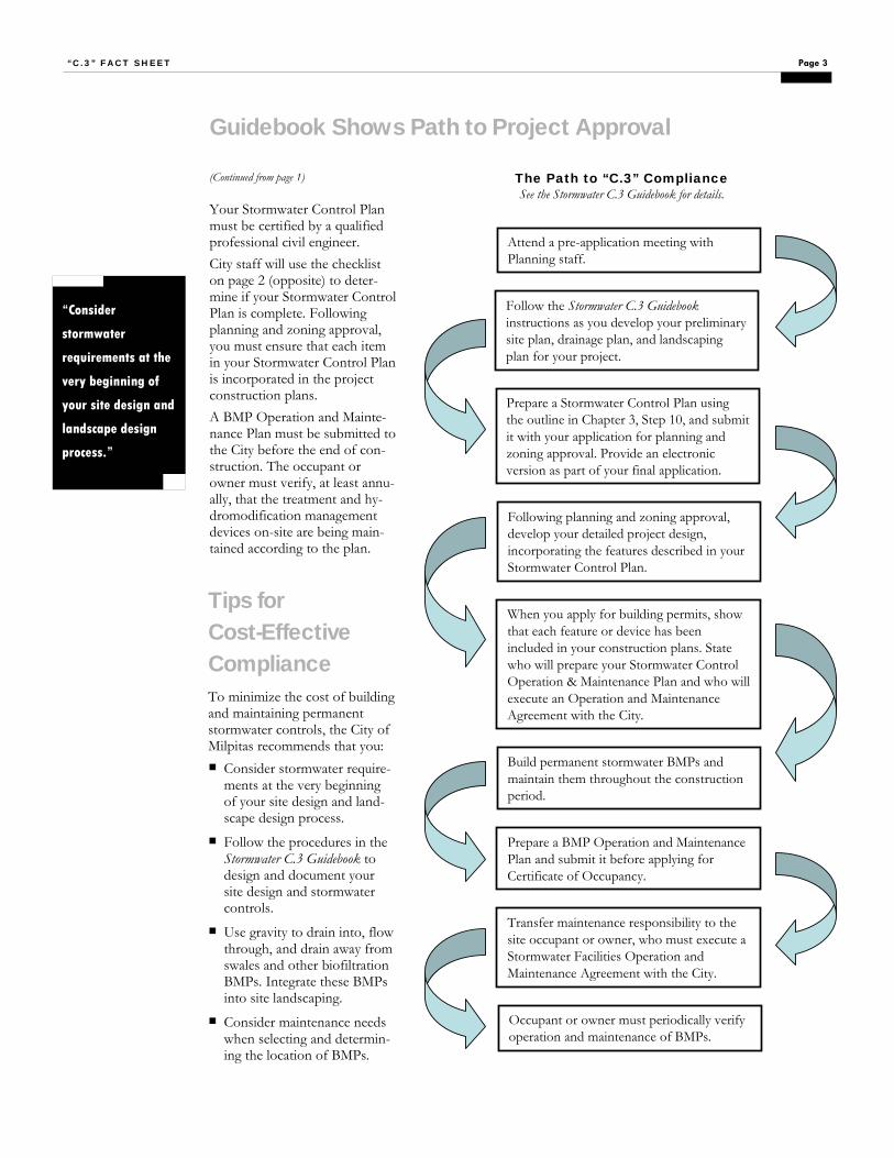
(Continued from page 1)
To minimize the cost of building and maintaining permanent stormwater controls, the City of Milpitas recommends that you: Consider stormwater require-ments at the very beginning of your site design and land-scape design process.
Follow the procedures in the Stormwater C.3 Guidebook to design and document your site design and stormwater controls.
Use gravity to drain into, flow through, and drain away from swales and other biofiltration BMPs. Integrate these BMPs into site landscaping.
Consider maintenance needs when selecting and determin-ing the location of BMPs.
Guidebook Shows Path to Project Approval
“Consider
stormwater
requirements at the
very beginning of
your site design and
landscape design
process.”
Page 3 “C.3” FACT SHEET
The Path to “C.3” Compliance See the Stormwater C.3 Guidebook for details.
Tips for Cost-Effective Compliance
Attend a pre-application meeting with Planning staff.
Follow the Stormwater C.3 Guidebookinstructions as you develop your preliminary site plan, drainage plan, and landscaping plan for your project.
Prepare a Stormwater Control Plan using the outline in Chapter 3, Step 10, and submit it with your application for planning and zoning approval. Provide an electronic version as part of your final application.
Following planning and zoning approval, develop your detailed project design, incorporating the features described in your Stormwater Control Plan.
Prepare a BMP Operation and Maintenance Plan and submit it before applying for Certificate of Occupancy.
Build permanent stormwater BMPs and maintain them throughout the construction period.
When you apply for building permits, show that each feature or device has been included in your construction plans. State who will prepare your Stormwater Control Operation & Maintenance Plan and who will execute an Operation and Maintenance Agreement with the City.
Transfer maintenance responsibility to the site occupant or owner, who must execute a Stormwater Facilities Operation and Maintenance Agreement with the City.
Occupant or owner must periodically verify operation and maintenance of BMPs.

To determine if your project must meet C.3 and/or HMP re-quirements, refer to the table below or to the C.3 flowchart in Chapter 1 of the Guidebook. For waiver and/or Alternative Compliance alternatives, refer to Chapter 7.
To determine what you need to submit to the City, whether you are granted a waiver or not, refer to the table below.
The HMP flowchart in Chapter 8 will help you determine whether your project must meet the HMP requirements.
Project Classifications
Project Classifica-
tion
Added or Replaced
Impervious Surface
“Deemed Complete”
C.3 Required
HMP Required
Group 1
On or after Oct. 15, 2003 On or after Oct. 6, 2005
Group 2A 10,000 square feet or more for projects of concern
On or after Oct. 6, 2005
Group 2B 10,000 square feet or more
On or after Aug. 15, 2006
1 acre (43,560 square feet) or more
C.3 Guidebook has specific instructions for docu-menting that stormwater treatment BMPs are sized to meet the Water Board requirements. By follow-ing these instructions closely, the applicant can help ensure efficient re-view of the Stormwater Control Plan.
Q: Can I use the proce-dures in the Santa Clara Valley Urban Runoff Pol-lution Prevention Pro-gram’s (SCVURPPP’s) C.3 Stormwater Handbook?
A: Follow the instructions in the City of Milpitas Stormwa-ter C.3 Guidebook. The SCVURPPP Handbook can be used as a technical refer-ence if needed. Q: Will Water Board staff be reviewing development projects?
A: Not for C.3 compliance. Municipal planning staff will review projects to ensure they comply with Provision C.3. If a project directly im-pacts a stream, the developer may also need to separately obtain a Section 401 Water Quality Certification from the Water Board. In addition,
Water Board staff may comment on
project CEQA documenta-
tion.
Q: Are Milpitas’ C.3 re-quirements different from those of neighboring cities and towns?
A: The Water Board has im-posed the same permit provi-sions on all municipalities in Santa Clara, Contra Costa, San Mateo, and Alameda Counties and on Fairfield, Suisun City, and Vallejo in Solano County. Implementa-tion schedules vary. Each municipality must de-termine how to integrate the C.3 requirements into their development review process. Milpitas’ procedures and guidance to applicants in-clude the following, which may be different from other municipalities: C.3 compliance must be
documented in the appli-cation for Planning and Zoning review. The applicant must pre-
pare a Stormwater Control Plan, following instruc-tions in the City’s Stormwa-ter C.3 Guidebook. Milpitas encourages the
use of planter boxes, swales, and other “bio-filtration” BMPs distrib-uted throughout the site and integrated into the land-scaping. The City’s
Stormwater
Q: What are the allowable pollutant discharge limits for stormwater?
A: There are no regulatory limits for the concentration of pollutants in stormwater discharges, nor are there cri-teria for the performance of stormwater treatment de-
Frequently Asked Questions
Does C.3 Apply to My Project?
A vegetated swale is one option for treating runoff from parking lots.
vices. Persons involved in activities which may produce stormwater pollutants must implement Best Management Practices (BMPs) to the maximum extent practicable. Provision C.3 does include criteria for sizing treatment devices.
Description No
Waiver
Waiver or Alternative Compliance
Granted
C.3 Data Form C.3 Waiver Form (and/or C.3 Alternative Compliance Form, if applicable) Stormwater Control Plan (SCP) Operation and Maintenance Plan Operation and Maintenance Agreement Hydromodification Management Form Hydromodification Management Plan
Required C.3 Submittals to the City

H O W T O U S E T H I S G U I D E B O O K
1
Start
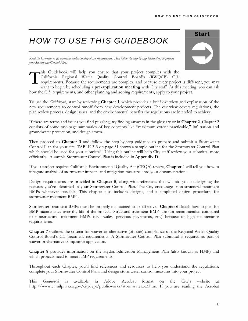
HOW TO USE THIS GUIDEBOOK
Read the Overview to get a general understanding of the requirements. Then follow the step-by-step instructions to prepare your Stormwater Control Plan.
his Guidebook will help you ensure that your project complies with the California Regional Water Quality Control Board’s (RWQCB) C.3. requirements. Because the requirements are complex, and because every project is different, you may want to begin by scheduling a pre-application meeting with City staff. At this meeting, you can ask
how the C.3. requirements, and other planning and zoning requirements, apply to your project.
To use the Guidebook, start by reviewing Chapter 1, which provides a brief overview and explanation of the new requirements to control runoff from new development projects. The overview covers regulations, the plan review process, design issues, and the environmental benefits the regulations are intended to achieve.
If there are terms and issues you find puzzling, try finding answers in the glossary or in Chapter 2. Chapter 2 consists of some one-page summaries of key concepts like “maximum extent practicable,” infiltration and groundwater protection, and design storm.
Then proceed to Chapter 3 and follow the step-by-step guidance to prepare and submit a Stormwater Control Plan for your site. TABLE 3-3 on page 31 shows a sample outline for the Stormwater Control Plan which should be used for your submittal. Using this outline will help City staff review your submittal more efficiently. A sample Stormwater Control Plan is included in Appendix D.
If your project requires California Environmental Quality Act (CEQA) review, Chapter 4 will tell you how to integrate analysis of stormwater impacts and mitigation measures into your documentation.
Design requirements are provided in Chapter 5, along with references that will aid you in designing the features you’ve identified in your Stormwater Control Plan. The City encourages non-structural treatment BMPs whenever possible. This chapter also includes designs, and a simplified design procedure, for stormwater treatment BMPs.
Stormwater treatment BMPs must be properly maintained to be effective. Chapter 6 details how to plan for BMP maintenance over the life of the project. Structural treatment BMPs are not recommended compared to nonstructural treatment BMPs (i.e. swales, pervious pavements, etc.) because of high maintenance requirements.
Chapter 7 outlines the criteria for waiver or alternative (off-site) compliance of the Regional Water Quality Control Board’s C.3 treatment requirements. A Stormwater Control Plan submittal is required as part of waiver or alternative compliance application.
Chapter 8 provides information on the Hydomodification Management Plan (also known as HMP) and which projects need to meet HMP requirements.
Throughout each Chapter, you’ll find references and resources to help you understand the regulations, complete your Stormwater Control Plan, and design stormwater control measures into your project.
This Guidebook is available in Adobe Acrobat format on the City’s website at http://www.ci.milpitas.ca.gov/citydept/publicworks/stormwater_c3.htm. If you are reading the Acrobat
T

C I T Y O F M I L P I T A S S T O R M W A T E R C . 3 G U I D E B O O K
2
version on a computer with an internet connection, you can use hyperlinks to navigate the document and to access various references. The hyperlinks are throughout the document, as well as in “References and Resources” sections and in the bibliography. Some references are on the City of Milpitas website; others are located at the websites of other organizations. Some of these latter links (URLs) may be outdated. In this case, you might try entering portions of the title or other relevant keywords into an internet search engine.

C H A P T E R 1 O V E R V I E W
3
Chapter
1 1 OVERVIEW
For a broad-based understanding, look at the Stormwater C.3. requirements from four different perspectives: as water-quality regulations, as planning requirements, as a design challenge, and as a way to obtain environmental benefits for the community.
1.1 STATE AND FEDERAL REGULATORY PERSPECTIVE
he California Regional Water Quality Control Board for the San Francisco Bay Region (RWQCB) has mandated that the City of Milpitas impose new, more stringent requirements to control runoff from development projects.
The RWQCB amended Provision C.3. of the City’s stormwater discharge permit in October 2001 and July 2005. The RWQCB has determined that the new Provision C.3. requirements are needed to implement Federal Clean Water Act provisions governing discharges from municipal storm drains.
Congress adopted amendments to the Clean Water Act in 1987, and the United States Environmental Protection Agency (USEPA) issued implementing regulations in 1990. That same year, the RWQCB first issued an initial stormwater discharge permit to Milpitas, 12 other South Bay cities and towns, the County of Santa Clara, and the Santa Clara Valley Water District.
Since the early 1990s, Milpitas has required contractors to implement temporary Best Management Practices (BMPs) to minimize the amount of sediment and other pollutants that enter site runoff during construction. For several years, Milpitas has also encouraged applicants to design their projects to minimize new impervious area and to incorporate into their plans permanent treatment BMPs — features and devices that detain, retain, or treat runoff for the life of the project.
As before, the standard for these BMPs is “maximum extent practicable,” or MEP. However, the new permit requirements define MEP more specifically and include design criteria.
The new development provisions are one part of the City’s comprehensive urban runoff pollution prevention program. That program also requires:
♦ Controls on runoff from existing commercial and industrial sites. ♦ Temporary measures to control sediment and other pollutants in runoff from construction sites. ♦ Changes in the way the City maintains streets, parks and public infrastructure. ♦ Prevention of illegal dumping in storm drains. ♦ Public outreach and education.
Under the RWQCB stormwater discharge permit, South Bay cities and other agencies implement some activities individually. Other activities are done jointly through the Santa Clara Valley Urban Runoff Pollution Prevention Program (SCVURPPP).
T
Clean Water Act Regulations on stormwater
discharges have grown progressively more stringent since the Clean Water Act was amended
in 1987.
“Maximum Extent Practicable”
For more on this and other stormwater terms, see the
Glossary and discussions in Chapter 2.
C I T Y O F M I L P I T A S S T O R M W A T E R C . 3 G U I D E B O O K
4
RWQCB staff monitors the City’s implementation of permit requirements. The City must report on its development review process, number and type of projects reviewed, and what runoff control measures were included in the projects.
As required by Permit Provision C.3.f., SCVURPPP developed, in cooperation with the Santa Clara Valley Water District, a Hydromodification Management Plan (HMP). The HMP identifies areas where runoff due to development increases the likelihood of erosion and other impacts to streams. In these areas, the RWQCB intends that post-project runoff flow and volume will not exceed pre-project rates or durations, and projects will need to meet requirements for flow control in addition to requirements for treatment of stormwater.
Chapter 8 discusses HMP requirements, applicable for Group 1 projects only at this time.
References and Resources • RWQCB Order No. 01-119 (Stormwater NPDES Permit Amendments) (Word document) • RWQCB Order 01-024 (Stormwater NPDES Permit) (Word document) • RWQCB Fact Sheet on New Development Provisions • RWQCB Water Quality Control Plan for the San Francisco Bay Basin (Basin Plan) • Clean Water Act Section 402(p) • 40 CFR 122.26(d)(2)(iv)(A)(2) – Stormwater Regulations for New Development • SCVURPPP – Urban Runoff Management Plan (1997) • City of Milpitas Urban Runoff Management Plan
1.2 LOCAL DEVELOPMENT REVIEW PERSPECTIVE
The City of Milpitas created this Guidebook to help project applicants implement the stormwater permit provision C.3 requirements. City staff aims to make these complex requirements clear and easy to follow. City staff will work with project applicants to facilitate timely and complete review of their projects.
► DOES C.3 APPLY TO YOUR PROJECT?
The RWQCB’s C.3 requirements apply to projects above specified thresholds depending on when projects are “deemed complete” as stated in the permit. The permit classified projects as either Group 1, Group 2A, or Group 2B.
Threshold Determines when C.3
requirements, including submitting a Stormwater Control Plan, are
required.
Private Projects Private projects are submitted and
approved by the Planning Division.
Public Projects Public projects are funded through
approval by the Milpitas City Council.
“Deemed Complete” PRIVATE PROJECTS are
“deemed complete” when the list of requirements needed for
planning application submittals (provided by the Planning
Division) is complete and ready to be processed. This list includes the
Stormwater Control Plan. PUBLIC PROJECTS are “deemed complete” when the City Council
approves DESIGN funding.
C H A P T E R 1 O V E R V I E W
5
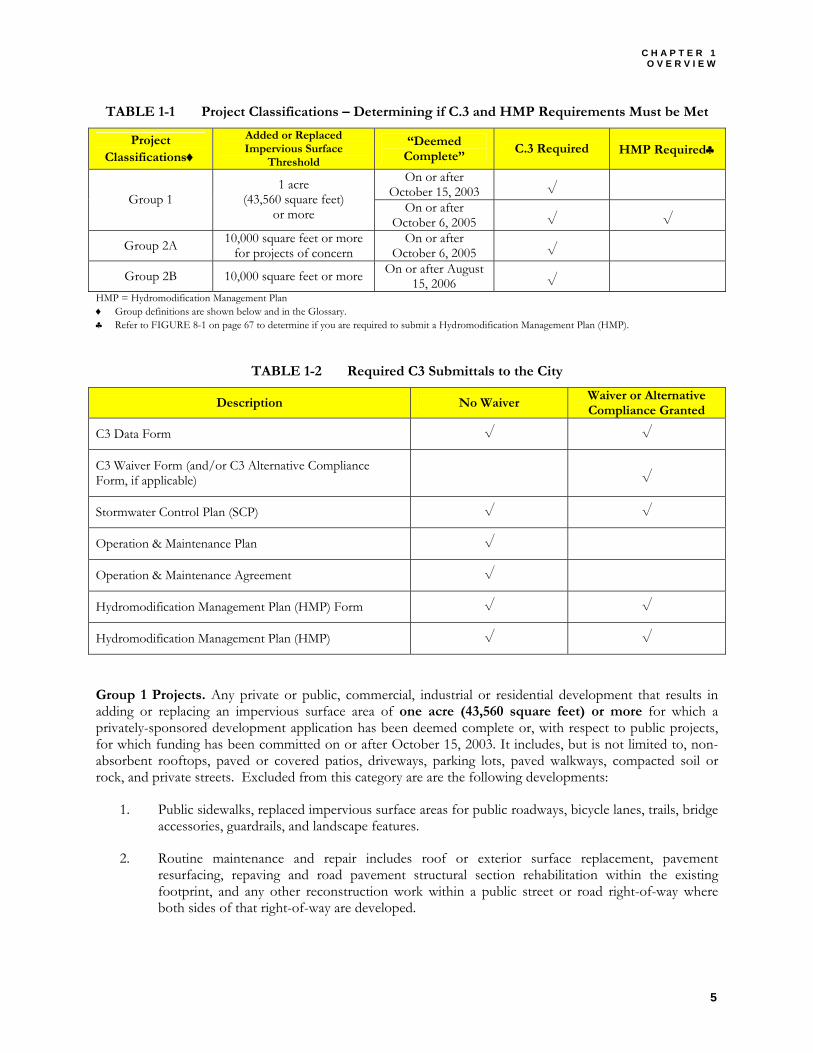
TABLE 1-1 Project Classifications – Determining if C.3 and HMP Requirements Must be Met
Project Classifications♦
Added or Replaced Impervious Surface
Threshold
“Deemed Complete”
C.3 Required HMP Required♣
On or after October 15, 2003 √
Group 1 1 acre
(43,560 square feet) or more On or after
October 6, 2005 √ √
Group 2A 10,000 square feet or more for projects of concern
On or after October 6, 2005 √
Group 2B 10,000 square feet or more On or after August 15, 2006 √
HMP = Hydromodification Management Plan ♦ Group definitions are shown below and in the Glossary. ♣ Refer to FIGURE 8-1 on page 67 to determine if you are required to submit a Hydromodification Management Plan (HMP).
TABLE 1-2 Required C3 Submittals to the City
Description No Waiver Waiver or Alternative Compliance Granted
C3 Data Form √ √
C3 Waiver Form (and/or C3 Alternative Compliance Form, if applicable) √
Stormwater Control Plan (SCP) √ √
Operation & Maintenance Plan √
Operation & Maintenance Agreement √
Hydromodification Management Plan (HMP) Form √ √
Hydromodification Management Plan (HMP) √ √
Group 1 Projects. Any private or public, commercial, industrial or residential development that results in adding or replacing an impervious surface area of one acre (43,560 square feet) or more for which a privately-sponsored development application has been deemed complete or, with respect to public projects, for which funding has been committed on or after October 15, 2003. It includes, but is not limited to, non-absorbent rooftops, paved or covered patios, driveways, parking lots, paved walkways, compacted soil or rock, and private streets. Excluded from this category are are the following developments:
1. Public sidewalks, replaced impervious surface areas for public roadways, bicycle lanes, trails, bridge accessories, guardrails, and landscape features.
2. Routine maintenance and repair includes roof or exterior surface replacement, pavement resurfacing, repaving and road pavement structural section rehabilitation within the existing footprint, and any other reconstruction work within a public street or road right-of-way where both sides of that right-of-way are developed.
C I T Y O F M I L P I T A S S T O R M W A T E R C . 3 G U I D E B O O K
6
3. Construction of one single family home that is not part of a larger common plan of development, with the incorporation of appropriate pollutant source control and design measures, and using landscaping to appropriately treat runoff from roof and house-associated impervious surfaces (e.g., runoff from roofs, patios, driveways, sidewalks, and similar surfaces).
Group 2A Projects. In all ways the Group 2A Project is the same as the Group 1 Project definition, (except with respect to implementation of Hydromodification Plan requirements), but the size threshold of impervious area is reduced from 1 acre (43,560 square feet) to 10,000 square feet, the privately-sponsored development application has been deemed complete or, with respect to a public project, the funding has been committed, on or after October 6, 2005, and the project is one of the following land use categories:
♦ Gas stations;
♦ Auto wrecking yards;
♦ Loading docks and surface parking lots containing more than 10,000 square feet or more of impervious surface area; and
♦ Vehicle or equipment maintenance areas (including washing and repair), outdoor handling or storage of waste or hazardous materials, outdoor manufacturing area(s), outdoor food handling or processing, outdoor animal care, outdoor horticultural activities, and various other industrial and commercial uses where potential pollutant loading cannot be satisfactorily mitigated through other post-construction source control and site design practices.
Group 2B Projects. In all ways the Group 2B Project is the same as the Group 2A Project definition, but applies to all projects with impervious areas of 10,000 square feet or more, and applies to all privately-sponsored development application that have been deemed complete or, with respect to public projects, for which funding has been committed, on or after August 15, 2006.
Hydromodification Management Plan (HMP). A plan for stormwater controls to manage applicable increases in peak runoff flow and increased runoff volume. HMP only applies to Group 1 Projects. Refer to Chapter 8.
FIGURE 1-2 on page 12 is a flowchart that can help you determine whether a project is required to meet the C3 provisions and submit a Stormwater Control Plan to the City. For details on the Waiver and Alternative Compliance alternatives, refer to Chapter 7.
► DEVELOPMENT REVIEW PROCESS
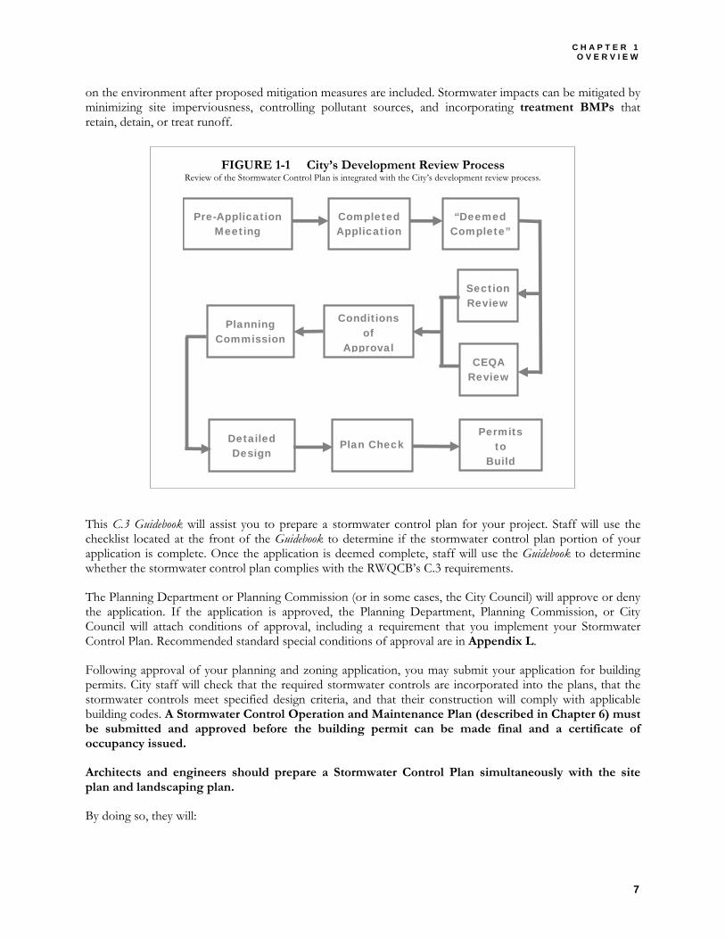
The process for reviewing stormwater controls is integrated with the City’s development review procedures. A simplified diagram of the procedures is shown in FIGURE 1-1 on page 7.
If the C.3 requirements apply, Planning Division staff will require that a Stormwater Control Plan be submitted along with the Planning and Zoning application. This should be discussed at the pre-application meeting.
If the project requires review under the California Environmental Quality Act (CEQA), Planning Staff will require submittal of an Environmental Information Form. This submittal should document potential impacts of the project’s changes to stormwater runoff. Staff will use an initial study checklist to determine whether the project may still have significant effects
CEQA See Chapter 4 for a discussion of
how to document stormwater impacts and mitigations in Initial
Studies and Environmental Impact Reports.
C H A P T E R 1 O V E R V I E W
7
on the environment after proposed mitigation measures are included. Stormwater impacts can be mitigated by minimizing site imperviousness, controlling pollutant sources, and incorporating treatment BMPs that retain, detain, or treat runoff.
FIGURE 1-1 City’s Development Review Process Review of the Stormwater Control Plan is integrated with the City’s development review process.
Pre-Application Meeting
Completed Application
“Deemed Complete”
Section Review
CEQA Review
Conditions of
Approval
Planning Commission
Detailed Design
Plan Check Permits
to Build
This C.3 Guidebook will assist you to prepare a stormwater control plan for your project. Staff will use the checklist located at the front of the Guidebook to determine if the stormwater control plan portion of your application is complete. Once the application is deemed complete, staff will use the Guidebook to determine whether the stormwater control plan complies with the RWQCB’s C.3 requirements.
The Planning Department or Planning Commission (or in some cases, the City Council) will approve or deny the application. If the application is approved, the Planning Department, Planning Commission, or City Council will attach conditions of approval, including a requirement that you implement your Stormwater Control Plan. Recommended standard special conditions of approval are in Appendix L.
Following approval of your planning and zoning application, you may submit your application for building permits. City staff will check that the required stormwater controls are incorporated into the plans, that the stormwater controls meet specified design criteria, and that their construction will comply with applicable building codes. A Stormwater Control Operation and Maintenance Plan (described in Chapter 6) must be submitted and approved before the building permit can be made final and a certificate of occupancy issued.
Architects and engineers should prepare a Stormwater Control Plan simultaneously with the site plan and landscaping plan.
By doing so, they will:
C I T Y O F M I L P I T A S S T O R M W A T E R C . 3 G U I D E B O O K
8
♦ Maximize multiple benefits of site landscaping. ♦ Reduce overall project costs. ♦ Improve site aesthetics and produce a better quality project. ♦ Be more likely to achieve “maximum extent practicable.” ♦ Speed project review. ♦ Avoid unnecessary redesign.
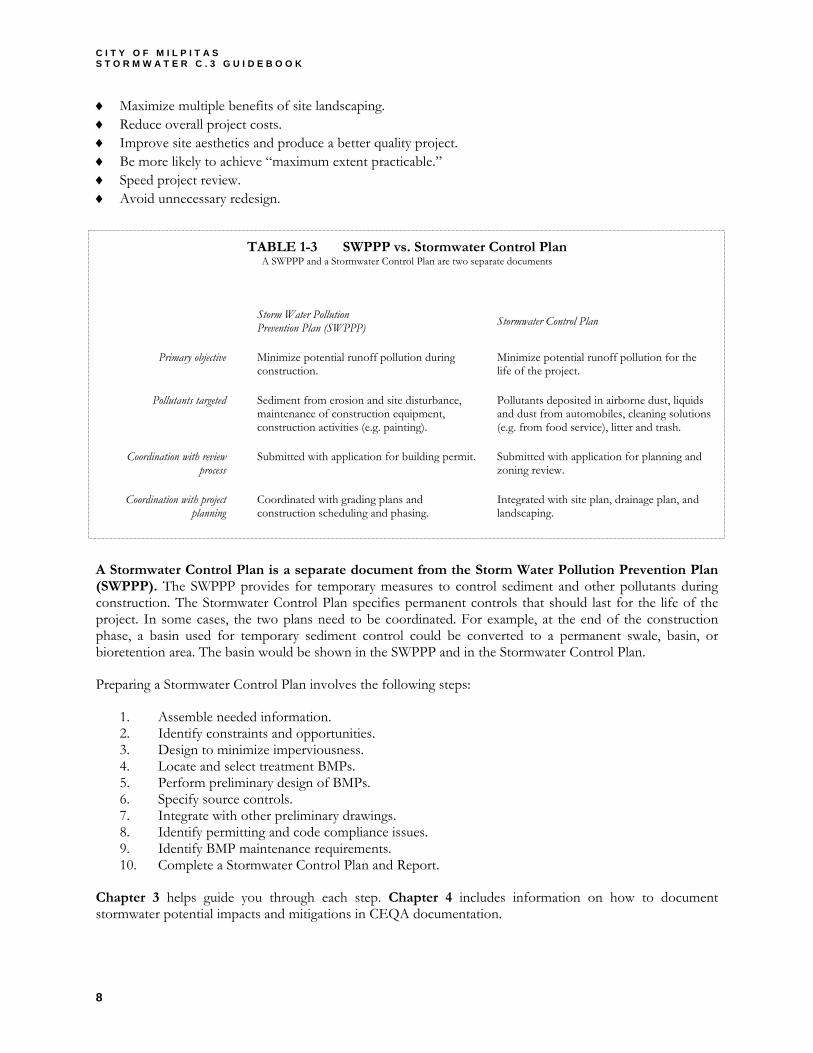
TABLE 1-3 SWPPP vs. Stormwater Control Plan A SWPPP and a Stormwater Control Plan are two separate documents
A Stormwater Control Plan is a separate document from the Storm Water Pollution Prevention Plan (SWPPP). The SWPPP provides for temporary measures to control sediment and other pollutants during construction. The Stormwater Control Plan specifies permanent controls that should last for the life of the project. In some cases, the two plans need to be coordinated. For example, at the end of the construction phase, a basin used for temporary sediment control could be converted to a permanent swale, basin, or bioretention area. The basin would be shown in the SWPPP and in the Stormwater Control Plan.
Preparing a Stormwater Control Plan involves the following steps:
1. Assemble needed information. 2. Identify constraints and opportunities. 3. Design to minimize imperviousness. 4. Locate and select treatment BMPs. 5. Perform preliminary design of BMPs. 6. Specify source controls. 7. Integrate with other preliminary drawings. 8. Identify permitting and code compliance issues. 9. Identify BMP maintenance requirements. 10. Complete a Stormwater Control Plan and Report.
Chapter 3 helps guide you through each step. Chapter 4 includes information on how to document stormwater potential impacts and mitigations in CEQA documentation.
Storm Water Pollution Prevention Plan (SWPPP) Stormwater Control Plan
Primary objective Minimize potential runoff pollution during construction.
Minimize potential runoff pollution for the life of the project.
Pollutants targeted Sediment from erosion and site disturbance, maintenance of construction equipment, construction activities (e.g. painting).
Pollutants deposited in airborne dust, liquids and dust from automobiles, cleaning solutions (e.g. from food service), litter and trash.
Coordination with review process
Submitted with application for building permit. Submitted with application for planning and zoning review.
Coordination with project planning
Coordinated with grading plans and construction scheduling and phasing.
Integrated with site plan, drainage plan, and landscaping.

C H A P T E R 1 O V E R V I E W
9
References and Resources: • RWQCB Order No. 01-119 (Stormwater NPDES Permit Amendments) Provisions C.3.(b) and C.3.(j) • California Planning, Zoning, and Development Law • California Environmental Quality Act • CEQA Deskbook 1999 [Second] Edition (Bass, Herson, and Bodan, Solano Press Books, 2001) • City of Milpitas Development Review Application Form • City of Milpitas Environmental Information Form • City of Milpitas Initial Study Checklist • California Building Code • California Stormwater Best Management Practice Handbook (Construction) • Manual of Standards for Erosion and Sediment Control Measures (ABAG, 1998)
1.3 PLANNING AND DESIGN PERSPECTIVE
In most cases, stormwater controls will add to the overall cost of a project. Stormwater controls may also constrain use of the site.
However, if executed well, and if integrated with landscaping and site amenities, stormwater controls can add to your project’s quality and value.
From a site design perspective, the aim of stormwater controls is to make site drainage mimic, as much as possible, the way a natural landscape drains.
Much of the rain falling on a natural landscape is held by vegetation, soaks into the soil, or seeps slowly downhill. Pollutants washed out from the atmosphere are absorbed through contact with soils and vegetation.
Roofs and paving prevent rain from reaching the soil. Pollutants wash off the impervious surfaces, and drain pipes transport the runoff rapidly and efficiently. Higher peak flows and runoff volumes promote channel erosion – unless streambanks are hardened.
Because most rainfall comes in small storms – and because small storms have cumulative and profound effects on stream channel stability – it makes sense to design stormwater controls to detain, retain, and treat runoff from small storms. In Milpitas, about 85% of average annual rainfall comes in storms of around one inch or less.
An obvious, and effective, way to limit site runoff is to minimize the amount of pavement and roofs. Some paved areas can be designed with unit pavers, gravel, or other pervious surfaces. Runoff from small paved areas, like sidewalk or driveway strips, can be sloped to drain to concave lawns or landscaping.
Runoff collected from larger impervious areas, like roofs or parking lots, can be channeled through features located in depressions and integrated into the landscape. These features include swales, infiltration/detention basins, and bioretention areas.
These treatment BMPs can help infiltrate runoff into the soil. If soils are impermeable or groundwater is too close to the surface—as in parts of Milpitas—the features can detain and treat runoff before it is allowed to slowly drain away.
Where space and site layout do not allow swales, basins, or bioretention areas, it is still possible to use vaults for storage and sand filters for treatment. These devices work, but are more expensive, require more maintenance, and generally do not contribute to site aesthetics.
Design Objective Make the site mimic, as much as
possible, the way a natural landscape drains.
C I T Y O F M I L P I T A S S T O R M W A T E R C . 3 G U I D E B O O K
10
Projects in the Bay Area, throughout the U.S., and in other countries have successfully implemented these techniques. Design manuals are available to guide architects and engineers through the design process, including the selection of options, sizing, and specifications.
Chapter 5 provides guidance on design requirements.
References and Resources • Start at the Source (BASMAA, 1999) • California Best Management Practice Handbooks (CASQA, 2003). • Urban Runoff Quality Management (WEF/ASCE, 1998) • Site Planning for Urban Stream Protection (Scheuler, 1995) • Urban Small Sites Best Management Practice Manual • Low Impact Development Design Strategies: An Integrated Approach (Maryland, 2001) • (Minneapolis/St. Paul) Metropolitan Council of Governments (Barr Engineering, 2001).
1.4 ENVIRONMENTAL BENEFIT PERSPECTIVE
The unusually diverse natural geography of the Santa Clara Basin—the area that drains to southerly South San Francisco Bay—includes tidal wetlands, alluvial plains, and mountain slopes. Annual rainfall varies from around 60 inches in the Santa Cruz Mountains to 15 inches or less in Milpitas and other parts of the Santa Clara Valley.
Milpitas’ climate and location on a broad alluvial plain give its streams a characteristic structure of riffles, pools, terraces, floodplains, and wetlands. In relatively undisturbed stream reaches, this geomorphic structure supports trees and other riparian vegetation. Trees provide shade (cooling stream temperatures), create root wads and undercut banks (refuge for fish) and produce falling leaves and detritus (the bottom of a food web). Fish, frogs, and other animals have evolved to thrive in riparian habitats. Because the habitats are diverse and complex, there are many species that are specialized, have limited ranges, and may be rare.
The landscape of Milpitas, like that of all the San Francisco Bay Area, has been repeatedly transformed since the Spanish arrived in the 1770s. Even before the area was developed, European grasses, weeds, and other plants replaced much of the native vegetation. Creek flows were diverted to irrigate farms; later, pumping lowered the groundwater table. Wetlands were diked to create salt evaporators or were filled for farmland.
Urban development came to Milpitas after the Second World War. To make flood-prone land suitable for development, creeks were channelized or confined within levees. Buildings, streets, and pavement now cover much of the land, and storm drains pipe runoff from urban neighborhoods directly into the creeks. Urbanization has changed the timing and intensity of stream flows and has set off a chain of unanticipated consequences. These consequences include more frequent flooding, destabilized stream banks, bank armoring, loss of streamside trees and vegetation, and the destruction of stream habitat.
The remaining habitat, even where it has been disturbed and reduced to remnants, is an important refuge for various species. The U.S. and California have listed some of these species as endangered, threatened, rare, or having other special status. The riparian habitat along Coyote Creek, including the portion within the City of Milpitas, provides some of the best remaining riparian habitat in Santa Clara County. The area may support burrowing owls and provides potential breeding habitat for various songbirds (including listed yellow warblers) and hunting grounds for raptors, including hawks and owls. Belted kingfishers have been seen flying over Coyote Creek and Berryessa Creek (Milpitas 2001).
In the foothills, riparian areas along creeks support a variety of songbirds and raptors. Insects that thrive in the vegetation provide a food source for bats and lizards, and tall trees may be nesting sites for orioles and
C H A P T E R 1 O V E R V I E W
11
hawks. Most of the creeks that wind across Milpitas’ alluvial plain remain unburied (although many are channelized). Existing and potential habitat within and along these creeks is not well documented.
Natural streams and their ecosystems cannot be fully restored. However, it is possible to stop, and partially reverse, the trend of declining habitat and preserve some ecosystem values for the benefit of future generations.
This is an enormous, long-term effort. The runoff from a single development site may seem inconsequential, but by changing the way sites are developed (and redeveloped), we may be able to preserve and enhance existing stream ecosystems in urban areas.
References and Resources • Restoring Streams in Cities (Riley, 1998) • Stream Restoration: Principles, Processes, and Practices (Federal Interagency Stream Restoration Working Group,
1998; updated 2001) • Santa Clara Basin Watershed Management Initiative Watershed Characteristics Report (SCBWMI, 2001) and
Watershed Action Plan (SCBWMI, 2003). • Coyote Creek Trail Public Draft Initial Study (City of Milpitas, 2001). • Santa Clara Valley Urban Runoff Pollution Prevention Program (SCVURPPP) Hydromodification Management Plan
Final Report (April 2005)
C H A P T E R 2 S T O R M W A T E R C O N C E P T S
13
Chapter
2 2 STORMWATER CONCEPTS
All about BMPs, MEP, imperviousness, etc.
ike practitioners in any other specialized field, planners and engineers working on stormwater control have created their own lingo. Within the array of acronyms and shorthand, there are several key concepts—some of them based on water-quality regulations, others on evolved design practice—that are indispensable to
communication between project proponents, designers, and reviewers.
The glossary near the back of this Guidebook lists words and concepts that can be explained adequately in a sentence or two. Other concepts require elaboration, including explanation of how they apply to designing and permitting development projects in the City of Milpitas.
This chapter explains the following key concepts:
♦ Maximum Extent Practicable ♦ Best Management Practices ♦ Imperviousness ♦ Design Storm
2.1 MAXIMUM EXTENT PRACTICABLE
As required by the Clean Water Act, the RWQCB limits the allowable concentration (and sometimes the allowable load) of pollutants in municipal and industrial wastewaters discharged to State waters.
When it amended the Clean Water Act in 1987, Congress recognized that it was not technically feasible to establish similar limits on pollutants discharged from municipal storm drains. Instead, Clean Water Act Section 402(p)(3)(iii) says that the states
shall require controls to reduce the discharge of pollutants to the maximum extent practicable, including management practices, control techniques and system, design and engineering methods, and such other provisions as the Administrator or the State determines appropriate for the control of such pollutants.
“Maximum extent practicable” is not defined in Federal law or regulation.
SCVURPPP’s 1997 Urban Runoff Management Plan (approved by the RWQCB) says that “maximum extent practicable” is subjective (i.e., it requires the exercise of individual judgment), evolving, and flexible. SCVURPPP’s plan emphasizes that the Co-permittees implement continuous improvement to insure that their programs consistently achieve “maximum extent practicable.”
Under the stormwater discharge permit, SCVURPPP regularly updates (and the RWQCB reviews and approves) model performance standards that establish, for various elements of the stormwater pollution prevention program, the level of effort that currently corresponds to “maximum extent practicable.”
L
C I T Y O F M I L P I T A S S T O R M W A T E R C . 3 G U I D E B O O K
14
When reviewing proposed development projects, Milpitas staff uses current performance standards and best professional judgment to determine whether proposed stormwater controls meet the “maximum extent practicable.”
As knowledge of stormwater control develops, it is becoming more common for “maximum extent practicable” to be expressed as numeric criteria. For example, the 2001 amendments to stormwater permit Provision C.3 established numeric standards for sizing stormwater treatment BMPs. City staff must apply these standards when reviewing proposed development projects.
For other aspects of site design and treatment BMP design, City staff may consult available design manuals and apply their engineering or other professional judgment.
2.2 BEST MANAGEMENT PRACTICES
Clean Water Act Section 402(p) and USEPA regulations (40 CFR 122.26) specify a municipal program of “management practices” to control stormwater pollutants. Best Management Practices (BMP) refers to any kind of procedure or device designed to minimize the quantity of pollutants that enter the storm drain system.
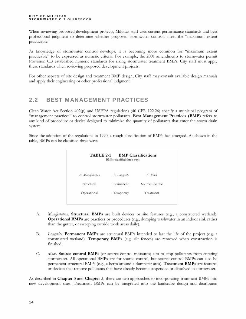
Since the adoption of the regulations in 1990, a rough classification of BMPs has emerged. As shown in the table, BMPs can be classified three ways:
TABLE 2-1 BMP Classifications BMPs classified three ways.
A. Manifestation. Structural BMPs are built devices or site features (e.g., a constructed wetland). Operational BMPs are practices or procedures (e.g., dumping washwater in an indoor sink rather than the gutter, or sweeping outside work areas daily).
B. Longevity. Permanent BMPs are structural BMPs intended to last the life of the project (e.g. a constructed wetland). Temporary BMPs (e.g. silt fences) are removed when construction is finished.
C. Mode. Source control BMPs (or source control measures) aim to stop pollutants from entering stormwater. All operational BMPs are for source control, but source control BMPs can also be permanent structural BMPs (e.g., a berm around a dumpster area). Treatment BMPs are features or devices that remove pollutants that have already become suspended or dissolved in stormwater.
As described in Chapter 3 and Chapter 5, there are two approaches to incorporating treatment BMPs into new development sites. Treatment BMPs can be integrated into the landscape design and distributed
A. Manifestation B. Longevity C. Mode
Structural Permanent Source Control
Operational Temporary Treatment
C H A P T E R 2 S T O R M W A T E R C O N C E P T S
15
throughout the site (integrated/distributed treatment BMPs), or site drainage can be piped to a single conventional treatment BMP. Many integrated/distributed treatment BMPs are flow-based BMPs—they treat runoff by filtering it continuously through soil. Detention basins, the most common type of conventional treatment BMP, are an example of a volume-based BMP. Volume-based BMPs treat stormwater primarily through settling or infiltration.
Commercial and industrial facilities must implement operational BMPs to the maximum extent practicable, and residents are expected to avoid allowing anything other than stormwater (e.g., soapy water, paint, litter) from entering storm drains. These requirements are implemented and enforced by other parts of the City of Milpitas’ comprehensive stormwater pollution prevention program.
2.3 IMPERVIOUSNESS
Schueler (1995) proposed imperviousness as a “unifying theme” for the efforts of planners, engineers, landscape architects, scientists, and local officials concerned with urban watershed protection. Schueler argued: (1) Imperviousness is a useful indicator linking urban land development to the degradation of aquatic ecosystems, and (2) Imperviousness can be quantified, managed, and controlled during land development.
Imperviousness has long been understood as the key variable in urban hydrology. Peak runoff flow and total runoff volume from small urban catchments is usually calculated as a function of the ratio of impervious area to total area (rational method). The ratio is represented as a runoff factor, usually designated “C”. Increased flows resulting from urban development tend to increase the frequency of small-scale flooding downstream.
Imperviousness links urban land development to degradation of aquatic ecosystems in two principal ways.
First, the combination of paved surfaces and piped runoff efficiently collects urban pollutants and transports them, in suspended or dissolved form, to surface waters. These pollutants may originate as airborne dust, be washed from the atmosphere during rains, or may be generated by automobiles and outdoor work activities.
Second, increased peak flows and runoff durations typically cause erosion of stream banks and beds, transport of fine sediments, and disruption of aquatic habitat. Measures taken to control stream erosion, such as hardening banks with riprap or concrete, may permanently eliminate habitat. By reducing groundwater infiltration, imperviousness may also reduce dry-weather stream flows.
Imperviousness has two major components: rooftops and transportation (including streets, highways, and parking areas). The transportation component is usually larger and is more likely to be directly connected to the storm drain system.
The effects of imperviousness can be mitigated by disconnecting impervious areas from the drainage system and by making drainage less efficient—i.e., by encouraging detention and retention of runoff near the point where it is generated. Detention and retention reduce peak flows and volumes and allow pollutants to settle out or adhere to soils before they can be transported downstream.

C I T Y O F M I L P I T A S S T O R M W A T E R C . 3 G U I D E B O O K
16
2.4 DESIGN STORM
No two rainstorms are exactly alike. Hydrologists sort and analyze rain gauge records to find long-term patterns of rainfall intensity and duration. Then they predict runoff flows and volumes based on these patterns and on the size, slopes, soils, land uses, and drainage patterns of a particular catchment.
Engineers select a design storm to calculate the required size of facilities that convey, store, or treat runoff. Because small storms occur many times a year, and larger storms come once in many years, the design storm is selected based on probability (e.g., the allowable likelihood that a channel will overflow in any given year). Often, applicable regulations specify the rainfall intensity and duration that must be used in design.
Different design storms apply to different purposes. Selection of a design storm balances costs and benefits. Roof leaders and flood control channels are typically designed to convey runoff from a storm with a one-in-one-hundred (1%) probability of occurring in any particular year (commonly called the “one-hundred-year storm”). Flood control detention basins may be designed to hold a storm predicted to occur, on average, in 4% or 10% of the coming years (a 25-year or 10-year storm, respectively).
NPDES permit Provision C.3.d includes criteria for designing treatment BMPs. These criteria target treatment of 80% of cumulative runoff. (See the discussion of maximum extent practicable on page 1.) Because most runoff is produced by small storms that occur many times a year, treatment BMPs can be designed to bypass larger storms. The 80% criterion means that BMPs will be bypassed, on average, every 1-2 years.
Because treatment BMPs are designed to treat only small storms, they can be considerably smaller than detention basins that are designed to protect property during flood-generating storms that may recur in 10%, 4%, or 1% of coming years. However, treatment BMPs must be designed as part of an overall drainage system that can accommodate larger storms.
Development sites subject to NPDES permit Provision C.3.f will be required to maintain runoff peak flows and durations that existed prior to development. The Hydromodification Management Plan (HMP) specifies locations where C.3.f applies and will also identify methods that must be used to compute peak flows and durations.
C H A P T E R 3 P R E P A R I N G Y O U R S T O R M W A T E R C O N T R O L P L A N
17
Chapter
3 3 PREPARING YOUR
STORMWATER CONTROL PLAN
Step-by-step assistance for site design and BMP selection.
repare your Stormwater Control Plan for submittal along with the other items staff has marked on the Planning Division’s “Check Sheet for Planning and Zoning Application.” Discuss specific requirements that may apply to your project at the pre-application meeting with City staff.
► OBJECTIVES.
Your Stormwater Control Plan should demonstrate that your project will incorporate site design characteristics, landscape features, and treatment BMPs that will minimize imperviousness, retain or detain stormwater, slow runoff rates, and reduce pollutants in post-development runoff to the maximum extent practicable.
A complete and thorough Stormwater Control Plan will enable Planning staff to verify that your project complies with these requirements. The City requires a Stormwater Control Plan for every applicable project so that City staff can document the City’s compliance with its RWQCB permit.
► CONTENTS.
Your Stormwater Control Plan will consist of a plan and a report. Staff will use the Stomwater Control Plan checklist (found on page 2 of the “C3” Fact Sheet) to evaluate the completeness of your Plan.
► STEP BY STEP
The City recommends that you plan and design your stormwater controls integrally with the site planning and landscaping for your project. It’s best to start with general project requirements and preliminary site design concepts; then prepare the detailed site design, landscape design, and stormwater control plan simultaneously.
Even if a site design has already been prepared, you can still incorporate adequate stormwater controls. However, because you’ll be working within the constraints of the design, you may be limited to selecting more expensive, higher-maintenance, and less aesthetically pleasing stormwater treatment options.
The following step-by-step procedure should optimize your design by identifying the best opportunities for stormwater controls early in the design process. Regardless of which design procedure you use, you should still review this chapter for explanation of expectations and requirements for your Stormwater Control Plan.
P
C I T Y O F M I L P I T A S S T O R M W A T E R C . 3 G U I D E B O O K
18
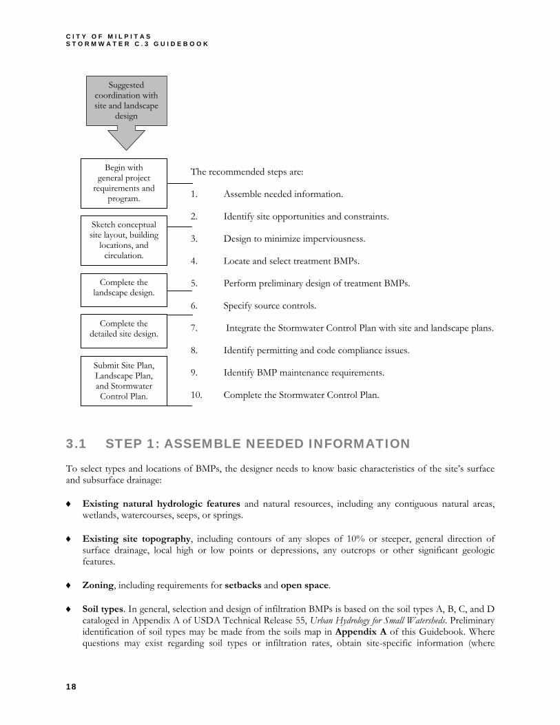
The recommended steps are:
1. Assemble needed information.
2. Identify site opportunities and constraints.
3. Design to minimize imperviousness.
4. Locate and select treatment BMPs.
5. Perform preliminary design of treatment BMPs.
6. Specify source controls.
7. Integrate the Stormwater Control Plan with site and landscape plans.
8. Identify permitting and code compliance issues.
9. Identify BMP maintenance requirements.
10. Complete the Stormwater Control Plan.
3.1 STEP 1: ASSEMBLE NEEDED INFORMATION
To select types and locations of BMPs, the designer needs to know basic characteristics of the site’s surface and subsurface drainage:
♦ Existing natural hydrologic features and natural resources, including any contiguous natural areas, wetlands, watercourses, seeps, or springs.
♦ Existing site topography, including contours of any slopes of 10% or steeper, general direction of surface drainage, local high or low points or depressions, any outcrops or other significant geologic features.
♦ Zoning, including requirements for setbacks and open space.
♦ Soil types. In general, selection and design of infiltration BMPs is based on the soil types A, B, C, and D cataloged in Appendix A of USDA Technical Release 55, Urban Hydrology for Small Watersheds. Preliminary identification of soil types may be made from the soils map in Appendix A of this Guidebook. Where questions may exist regarding soil types or infiltration rates, obtain site-specific information (where
Sketch conceptual site layout, building
locations, and circulation.
Complete the detailed site design.
Complete the landscape design.
Begin with general project
requirements and program.
Suggested coordination with site and landscape
design
Submit Site Plan, Landscape Plan, and Stormwater Control Plan.
C H A P T E R 3 P R E P A R I N G Y O U R S T O R M W A T E R C O N T R O L P L A N
19
available) from site inspection, boring logs, or geotechnical studies associated with previous design or construction.
♦ Depth to groundwater. The City has mapped areas where groundwater is shallow enough to infiltrate the sewer system. See Appendix B. This includes most (but not all) of the City west of Highway 680. Additional sources for groundwater elevations include:
Records of the Santa Clara Valley Water District Records from the City’s domestic wells. Results from geotechnical studies associated with previous design and construction for the site.
♦ Existing site drainage. For undeveloped sites, information on existing site drainage may be obtained by inspecting the site and examining topographic maps and survey data. For previously developed sites, site drainage and connection to the City storm drain system should be located from site inspection, City storm drain maps (available from the Land Development Section, Engineering Division), and plans for previous development. It may be possible to locate drainage plans submitted with previous building permit applications.
References and Resources • Appendix A, City of Milpitas Soils Map • Appendix B, City of Milpitas Groundwater Elevation Map • USDA SCS Technical Release TR55, Appendix A: Soil Types • City of Milpitas Municipal Code, Title XI, Chapter 10 (Zoning)
3.2 STEP 2: IDENTIFY CONSTRAINTS & OPPORTUNITIES
Review the information collected in Step 1. Identify the principal constraints on site design and BMP selection as well as opportunities to reduce imperviousness and incorporate BMPs into the site and landscape design. For example, constraints might include impermeable soils, high groundwater, steep slopes, geotechnical instability, high-intensity land use, heavy pedestrian or vehicular traffic, or safety concerns. Opportunities might include existing natural areas, low areas, oddly configured or otherwise unbuildable parcels, landscape amenities including open space and buffers (which can double as locations for BMPs), and differences in elevation (which can provide hydraulic head for BMPs).
Prepare a brief narrative describing site opportunities and constraints. In the review process, this narrative may help establish the maximum extent practicable degree of stormwater control for your site.
3.3 STEP 3: DESIGN TO MINIMIZE IMPERVIOUSNESS
► CLUSTER DEVELOPMENT
Chapter 4 of Start at the Source (BASMAA, 1999) lists the following design principles which can be applied to the layout of newly developed and redeveloped sites:
♦ Define development envelope and protected areas, identifying areas that are most suitable for development and areas that should be protected.
♦ Set back development from creeks, wetlands, and riparian habitats.

C I T Y O F M I L P I T A S S T O R M W A T E R C . 3 G U I D E B O O K
20
♦ Preserve significant trees. (Note: City Ordinance MMCX-2 defines “protected” trees and “heritage and specimen plantings.”)
♦ Avoid erodible soils and steep slopes.
Where possible, conform the site layout along natural landforms, avoid excessive grading and disturbance of vegetation and soils, and replicate the site’s natural drainage patterns.
For new subdivisions, the Milpitas General Plan encourages the use of Planned Unit Developments (PUDs) both on hillsides and the valley floor. Development within PUDs should be clustered to maximize open space, minimize lot sizes, minimize imperviousness and reduce other environmental impacts. A simple four-step procedure to lay out clustered subdivisions has been used throughout the U.S. (Natural Lands Trust, 2001):
1. Identify land that should be permanently protected.
2. Locate the sites of individual houses within the development area so that their views of the open space are maximized.
3. “Connect the dots” with streets and informal trails.
4. Draw the lot lines.
In residential subdivisions, imperviousness can be further reduced by designing shared driveways and by minimizing the number and size of cul-de-sacs.
► OPTIMIZE THE SITE LAYOUT
For all types of development, limit overall coverage of paving and roofs. As is detailed in Start at the Source, this can be accomplished by designing compact, taller structures, narrower streets and sidewalks, smaller parking lots (fewer stalls, smaller stalls, and more efficient lanes), and indoor or underground parking. Examine site layout and circulation patterns and identify areas where landscaping or planter boxes can be substituted for pavement.
► MINIMIZE DIRECTLY CONNECTED IMPERVIOUS AREA
With the built and landscaped areas defined on a site drawing, look for opportunities to minimize directly connected impervious area:
♦ Direct runoff from impervious areas to adjacent pervious areas or depressed landscaped areas. A 1:1 ratio of impervious to pervious area is generally acceptable; a 2:1 or higher (impervious/pervious) ratio may be appropriate where soils permit (except in hillside areas). Much higher ratios (over 20:1) can be used with an appropriately designed landscape infiltration/ bioretention BMP, which may require a subsurface liner and drainage.
♦ Select permeable pavements and surface treatments. Inventory the site’s paved areas and identify locations where permeable pavements, such as crushed aggregate, turf block, or unit pavers can be substituted for impervious concrete or asphalt paving.
C H A P T E R 3 P R E P A R I N G Y O U R S T O R M W A T E R C O N T R O L P L A N
21
► DETAIN AND RETAIN RUNOFF THROUGHOUT THE SITE
♦ Use drainage as a design element. Use above-ground drainage swales, depressed landscape areas, vegetated buffers, and bioretention areas as amenities and focal points within the site and landscape design. In some cases, swales can be placed within the street right-of-way to convey and treat stormwater runoff from roadways.
♦ Minimize peak flow and volume of runoff. Design landscaped areas and treatment BMPs (Steps 4 and 5) to detain or retain runoff. Refer to Chapter 8 which contains more information on Hydromodification Management Plan (HMP) requirements.
► DOCUMENT YOUR SITE DESIGN MEASURES
Chapter 5 describes how to document pervious and impervious areas within your project and how to quantify the benefits achieved by your design decisions to reduce paved and roofed area, to create self-retaining landscaped areas and pervious pavements, and to direct runoff from impervious to pervious areas. It includes instructions for using the provided spreadsheet to create a table of pervious areas within your site.
To accompany the table, prepare a brief narrative that documents the site layout and site design decisions (site design measures) you made that minimize imperviousness, retain or detain stormwater, slow runoff rates, and reduce pollutants in post-development runoff to the maximum extent practicable.
References and Resources • Start at the Source (BASMAA, 1999). • Growing Greener (Natural Lands Trust, 2001). • City of Milpitas General Plan (Milpitas, 1994). • City of Milpitas Municipal Code, Title XI, Chapter 10 (Zoning) • City of Milpitas “Planned Unit Development” web page • Low Impact Development Manual (Maryland, 1999). • Site Planning for Urban Stream Protection (Schueler, 1995). • SCVURPPP Summary of Site Design Dialogue Results, Appendix C in the SCVURPPP C.3 Stormwater Handbook • SCVURPPP Developments Protecting Water Quality: Guidebook of Site Design Examples
3.4 STEP 4: LOCATE AND SELECT TREATMENT BMPS
In Step 3, you minimized the total quantity of runoff by reducing impervious area and directing some runoff to pervious areas. You also sketched the site’s drainage system, divided the site into drainage areas, and tabulated pervious areas.
In this step, inventory and tabulate impervious areas and identify appropriate locations for stormwater treatment BMPs that will capture, then retain, detain, or treat the remaining runoff before it flows offsite. Then select the appropriate stormwater treatment BMPs. The opportunities and constraints identified earlier (in Step 2) will help guide this process.
There is no hard-and-fast procedure or set of rules for selecting treatment BMPs. Selection is ultimately by the designer’s professional judgment and preference, but the suite of BMPs selected must meet the criteria in the RWQCB permit.
A first consideration in identifying a drainage and treatment strategy is to decide whether infiltration is a practical option for the site. In general, the cheapest and most effective treatment BMPs are adequately sized
C I T Y O F M I L P I T A S S T O R M W A T E R C . 3 G U I D E B O O K
22
infiltration areas that are designed into site landscaping. In sites with space constraints, infiltration can be promoted by using surface infiltration basins or subsurface trenches or dry wells.
Infiltration may not be used where:
♦ The infiltration BMP would receive drainage from areas where chemicals are used or stored, where vehicles or equipment are washed, or where refuse or wastes are handled.
♦ Surface soils are polluted.
♦ The BMP could receive sediment-laden runoff from disturbed areas or unstable slopes.
♦ Soils are insufficiently permeable to allow the BMP to drain within 48 hours.
Infiltration BMPs may also be infeasible because of steep slopes, geotechnical instability, high groundwater, low-permeability soils, or a combination of these factors.
Special restrictions apply to the following infiltration devices that, as designed, may bypass filtration through surface soils before reaching groundwater:
♦ Infiltration basins.
♦ Infiltration and exfiltration trenches (includes french drains).
♦ Unlined retention basins (i.e., basins with no outlets.
♦ Unlined or open-bottomed vaults or boxes installed below grade (includes bubble ups and permeable pavement with underground storage).
These restrictions are detailed in Chapter 5.
On sites where infiltration is not feasible, BMPs will use detention and treatment, rather than infiltration, to manage runoff.
For sites that use detention and treatment, the primary limiting design factors will be available space and available hydraulic head (difference in water surface elevation between inflow and outflow). In some cases, a small adjustment of elevations within the site plan can make a treatment option feasible and cost-effective.
A second consideration in developing a drainage and treatment strategy is whether to route most or all drainage through a single detention and treatment BMP or to disperse smaller BMPs throughout the site. Piping runoff to a single treatment area may be simpler and easier to design, but designs that integrate swales, small landscaped areas, and planter boxes throughout the site can be more cost-effective and aesthetically pleasing.
► GUIDANCE FOR SELECTING BMPS
Chapter 5 includes a gallery of widely applicable BMPs that can be integrated into site landscaping and distributed throughout the site (integrated/distributed BMPs).
Low Impact Development Strategies: An Integrated Design Approach (Prince George’s County, Maryland, Department of Environmental Resources, 1999) guides the designer through the Low Impact Development (LID)
C H A P T E R 3 P R E P A R I N G Y O U R S T O R M W A T E R C O N T R O L P L A N
23
approach to stormwater control, which emphasizes small, cost-effective widely distributed landscape features rather than larger facilities located at the bottom of drainage areas.
Urban Runoff Quality Management (Water Environment Federation Manual of Practice No. 23; American Society of Civil Engineers Manual and Report on Engineering Practice No. 87) focuses on larger, conventional treatment BMPs. For areas with less permeable soils (NRCS Soil Types C & D), and where nutrients are not a major concern, this manual recommends extended detention, ponds with permanent pools, constructed wetlands, or media filtration.
Either approach may be best for a particular site, or elements of both approaches may be combined. In addition to the WEF/ASCE Manual and Low Impact Development manual, the City of Portland’s Stormwater Manual (revised 2004) includes many design details for treatment BMPs. CASQA’s California Stormwater BMP Handbook (New Development) includes fact sheets for a variety of treatment BMPs.
The City of Milpitas maintains a library of manuals and other design guides for your reference. Staff will provide information on how to obtain paper or electronic copies. These manuals should be used as a starting point for selection and design of treatment BMPs that meet the RWQCB requirements and City of Milpitas codes. Keep in mind that the criteria and recommendations in these manuals may be different, or inapplicable, to projects in the City of Milpitas.
The overall design for the site must meet RWQCB requirements, City of Milpitas planning and zoning requirements, and City of Milpitas building codes.
The designs must also be maintainable. Maintenance requirements for BMPs must be identified in the Stormwater Control Plan. A Stormwater BMP Operation and Maintenance Plan will be required at the time of building permit final and application for a Certificate of Occupancy.
► LOCATING TREATMENT BMPS ON YOUR SITE
Finding the right location for treatment BMPs on your site involves a careful and creative integration of several factors:
♦ For effective, low-maintenance operation, locate BMPs along the hydraulic grade line of the site’s drainage. Find the right location so drainage into and out of the device is by gravity flow. Pumped systems can be feasible, but are expensive, require more maintenance, are prone to untimely failure, and can cause mosquito control problems. Most stormwater BMPs require a minimum 2-3 feet of head.
♦ Consider final ownership and maintenance responsibility. If the BMP will serve only one site owner, make sure it is located for ready access by inspectors from the City and the Santa Clara County Vector Control District. If the property is being subdivided now or in the future, the BMP should be in a common, accessible area. In particular, avoid locating BMPs on private residential lots.
♦ The BMP must be accessible to equipment needed for its maintenance. Access requirements for maintenance will vary with the type of BMP selected. For example, planter boxes or biofiltration swales will typically need access for the same types of equipment used for landscape maintenance. Wet or dry detention ponds typically require maintenance roads that can be used by heavy vehicles for dredging and control of emergent vegetation. Vaults and underground filters may require special equipment for periodic clean out and media replacement. See Chapter 6 for typical maintenance requirements for various types of BMPs.
C I T Y O F M I L P I T A S S T O R M W A T E R C . 3 G U I D E B O O K
24
♦ To make the most efficient use of the site and to maximize aesthetic value, integrate BMPs with site landscaping. The City’s zoning code requires landscape setbacks for many types of development, and also may also specify that a minimum portion of the site be landscaped. It may be possible to locate some or all of your site’s treatment BMPs within this same area.
References and Resources • RWQCB Order 01-119, Provision C.3.d • Urban Runoff Quality Management (WEF/ASCE, 1998). • Low Impact Development Manual (Prince Georges County, 1999). • Start at the Source (BASMAA, 1999). • Stormwater Manual (Portland, 2002). • California Stormwater BMP Handbooks • Minnesota Urban Small Sites BMP Manual (Barr Engineering, 2001)
3.5 STEP 5: PERFORM PRELIMINARY DESIGN OF BMPS
Demonstrate the feasibility and effectiveness of the treatment BMPs you selected by showing that they meet the design criteria in Chapter 5. Detailed construction drawings are not required at this stage, but drawings or sketches should be included as needed to illustrate the proposed design and to support calculations.
Chapter 5 includes a set of widely applicable BMPs that can be integrated into the landscape and distributed throughout the site (integrated/distributed BMPs). Chapter 5 also provides a method of accounting for pervious and impervious areas and for demonstrating that the suite of BMPs you choose is sufficient to meet the RWQCB permit requirements. The City recommends that you use this procedure in preparing your Stormwater Control Plan.
3.6 STEP 6. SPECIFY SOURCE CONTROL BMPS
Some everyday activities – such as trash recycling/disposal and washing vehicles and equipment – generate pollutants that tend to find their way into storm drains. These pollutants can be minimized by applying source control BMPs (source control measures).
Source control BMPs include permanent, structural features that must be incorporated into your project plans and operational BMPs, such as regular sweeping and “housekeeping,” that must be implemented by the site’s occupant or user. The maximum extent practicable standard typically requires both types of BMPs; in general, operational BMPs cannot be substituted for a feasible and effective permanent BMP.
Use the following procedure to specify source control BMPs for your site:
► IDENTIFY POLLUTANT SOURCES
Review your preliminary site plan. Then review the first column in the table of source control measures (Appendix C). Check off the sources of potential pollutants that apply to your site and note the corresponding locations on the site plan.

C H A P T E R 3 P R E P A R I N G Y O U R S T O R M W A T E R C O N T R O L P L A N
25
► IDENTIFY PERMANENT SOURCE CONTROL MEASURES
Use the Source Control Measures table (Appendix C) to prepare a table listing each potential source on your site and the corresponding permanent, structural BMPs used to prevent pollutants from entering runoff. This will provide a guide to Source Control Measures that will be included in your building permit application.
TABLE 3-1 Format for Permanent Source Control BMPs
► IDENTIFY OPERATIONAL SOURCE CONTROL BMPS
Again referring to the Source Control Measures table (Appendix C), prepare a list of operational BMPs that should be implemented continually as long as the anticipated activities uses continue at the site. The City’s Urban Runoff ordinance requires that these BMPs be implemented; the same BMPs may also be required as a condition of a use permit or other revocable discretionary approval for use of the site.
► IDENTIFY PESTICIDE REDUCTION MEASURES
Provision C.9.d(ii) of the stormwater NPDES permit requires the City to:
Implement mechanisms to discourage pesticide use at new development sites. Such mechanisms shall encourage the consideration of pest-resistant landscaping and design features, minimization of impervious surfaces, and incorporation of stormwater detention and retention techniques in the design, landscaping, and/or environmental reviews of proposed development projects. Education programs shall target individuals responsible for these reviews and focus on factors affecting water quality impairment.
In your Stormwater Control Plan, identify any landscaping and design features that may help minimize use of pesticides during the life of the project. For example1:
♦ Reduce the potential for pesticides to run off the landscape by designing the landscape for efficient irrigation and drainage. Where possible, design the landscape to conform to natural drainage patterns.
♦ Reduce the amount of chemicals necessary to ensure healthy plants or eliminate the need for pesticide use at all by retaining existing native pest-resistant trees, shrubs, and plants.
♦ Select pest-resistant plants adapted to the Milpitas area. Consider site-specific characteristics such as soil, topography, climate, amount and timing of sunlight, prevailing winds, rainfall, air movement, patterns of land use, ecological consistency, and plant interactions. See the plant list in Appendix J. Landscape
1 Example landscaping and design features are adapted from SCVURPPP’s fact sheet, “Landscape Maintenance Techniques for Pest Reduction.”
The fact sheet is in Appendix K.
Potential source of runoff pollutants Permanent source control BMPs
C I T Y O F M I L P I T A S S T O R M W A T E R C . 3 G U I D E B O O K
26
architects, arborists, and Integrated Pest Management (IPM) specialists may be able to identify hardy species appropriate to your site.
♦ Where landscaped areas are used to retain or detain stormwater, specify plants that are tolerant of saturated soil conditions.
♦ Prevent the need for routine pruning by selecting plants based on their size and shape when mature.
♦ Situate plants to facilitate maintenance. Install mowing strips, tree wells, and pathway edging to reduce problems associated with maintaining the interface between different elements of the design.
♦ Plant at the right time of year.
References and Resources • Appendix C, Sources of Runoff Pollutants and Source Control BMPs • RWQCB Order 01-119, Provision C.3.k • SCVURPPP Model List of Source Control Measures • SCVURPPP Model Conditions of Approval for Pesticide Reduction in Landscaping Plans • SCVURPPP Landscape Maintenance Techniques for Pest Reduction • Start at the Source, Section 6.7: Details, Outdoor Work Areas • California Stormwater Industrial/Commercial Best Management Practice Handbook • Urban Runoff Quality Management (WEF/ASCE, 1998) Chapter 4: Source Controls
3.7 STEP 7: INTEGRATE WITH OTHER PRELIMINARY DRAWINGS.
Depending on the complexity of the project, the Stormwater Control Plan drawing may be combined with the site plan, landscape plan, or drainage plan. In any case, the Stormwater Control Plan should be carefully coordinated with these plans and with site grading and drainage.
Here are some typical considerations that may arise in coordinating Stormwater Control Plans with other aspects of the project preliminary design:
Building Drainage. Building codes require that drainage from roofs and impervious areas be drained away from the building. The codes also specify minimum sizes and slopes for roof leaders and drain piping. Detailed designs of BMPs located in or on the building, or within 10 feet of building foundations, must accommodate these codes while also meeting the minimum requirements for detention or flow stated in Provision C.3.
Control of elevations. Distribution of overland flow to landscaped areas may require that grading and landscape plans be executed with greater attention to slopes and elevations.
Drainage Plans. The City may require a drainage plan when the project final design is submitted for plan check. The drainage plan is designed to prevent street flooding during a 10-year storm and successfully route flows from a 100-year storm. To meet the requirements for both the Stormwater Control Plan design storm and the Drainage Plan design storm, BMP designs must incorporate bypasses or overflows to route excess flows to the storm drain system. It may be necessary to complete a preliminary drainage plan at the planning and zoning review stage.

C H A P T E R 3 P R E P A R I N G Y O U R S T O R M W A T E R C O N T R O L P L A N
27
Plant selection. Depressed landscaped areas, bioretention areas, vegetated swales, and many other BMPs require appropriate plant selection to work properly. This plant selection should be coordinated with or incorporated into the landscape plan. The City of Milpitas requires landscaping to be designed for water conservation (City Code, Title VIII, Chapter 5, Water Efficient Landscapes) and also requires that potable water not be used for irrigation where recycled water is available (Title VII, Chapter 6, Water Conservation).
Access for periodic maintenance. All BMPs will require access for periodic inspection in accordance with an approved maintenance plan. Many BMPs (e.g., bioretention basins and swales) require relatively little maintenance, but others (e.g., sand filters or proprietary devices) may require regular replacement of surface sand or replacement of cartridges or inserts. Site plans should provide for the necessary access for personnel and equipment.
Organizing traffic and parking. Your stormwater control plan may call for depressing landscaped areas below paved areas, rather than setting them above paved areas and surrounding them with curbs. Striping or bollards may be needed to guide traffic. Parking lots with crushed aggregate, unit-paver, and other permeable pavements may require bollards, signs, or other indicators to organize parking.
References and Resources • Milpitas Municipal Code • City of Milpitas. Engineering Division, Standard Drawings
3.8 STEP 8: PERMITTING & CODE COMPLIANCE ISSUES.
To meet the RWQCB’s “maximum extent practicable” standard, Stormwater Control Plans will typically need to incorporate innovative site design features, pavements, drainage design practices, and BMPs. Because these practices are new, they may be inconsistencies with existing building codes, engineering requirements, and standard conditions of approval.
The City makes no representation that the design practices or recommendations in this guidebook (or in the publications listed as references and in the bibliography) meet existing applicable codes or standards.
Where conflicts occur between recommended stormwater control practices and existing codes and standards, City staff will work with the applicant to identify one or more regulatory or design solutions that can satisfy all applicable requirements.
The City encourages you to identify these potential conflicts in the Planning and Zoning Review phase and to document the potential conflicts in the Stormwater Control Plan. By doing so, it may be possible to resolve the issue prior to final design. This will help avoid the need for redesign and resubmittal of final plans and associated project delays.
3.9 STEP 9: IDENTIFY BMP MAINTENANCE NEEDS
As required by NPDES Permit Provision C.3.e, the City will periodically verify that treatment BMPs are maintained and continue to operate as designed.
Ongoing maintenance of treatment BMPs will be the responsibility of the property owner.

C I T Y O F M I L P I T A S S T O R M W A T E R C . 3 G U I D E B O O K
28
Planning for operation and maintenance of treatment BMPs on your site is a seven-step process:
1. Confirm BMP ownership and maintenance responsibility.
2. In your Stormwater Control Plan, identify general maintenance requirements for the treatment BMPs on your site and state your intent to execute an operation and maintenance agreement with the City.
3. In your construction documents, provide contact information for the person responsible for preparing a detailed Stormwater Control Operation and Maintenance Plan. Also, provide contact information for the person who will execute a required operation and maintenance agreement with the City
4. Maintain treatment BMPs during site preparation and construction.
5. Develop and submit a detailed Stormwater Control Operation and Maintenance Plan prior to applying for a Certificate of Occupancy.
6. Formally transfer operation and maintenance responsibility by executing a Stormwater Management Facilities Operation and Maintenance Agreement.
7. Property owner or occupant must maintain stormwater treatment BMPs and complete annual inspections as required by the City.
See Chapter 6 for details of each step. Instructions for preparing a detailed Stormwater Control Operation and Maintenance Plan are in Appendix H.
► BMP MAINTENANCE INFORMATION IN YOUR STORMWATER CONTROL PLAN
Your Stormwater Control Plan should include a general description of anticipated BMP maintenance requirements. This will help insure that:
♦ Ongoing costs of maintenance have been considered in your BMP selection and design.
♦ Site and landscaping plans provide for access by maintenance equipment.
♦ Landscaping plans incorporate irrigation requirements for BMP plantings.
♦ Initial maintenance and replacement of BMP plantings is incorporated into landscaping contracts and guarantees.
Chapter 6 includes a discussion of typical maintenance requirements for some commonly used BMPs.
► OUTREACH ACTIVITIES FOR PESTICIDE REDUCTION
In your Stormwater Control Plan, acknowledge having reviewed the fact sheet, “Landscape Maintenance Techniques for Pest Reduction” in Appendix K of this Guidebook. In addition, City staff can provide you with additional information and brochures about pesticide reduction. Or you can visit www.watershedwatch.net.

C H A P T E R 3 P R E P A R I N G Y O U R S T O R M W A T E R C O N T R O L P L A N
29
References and Resources • Appendix H, Preparing Your Stormwater Control Operation and Maintenance Plan • Start at the Source (BASMAA, 1999) pp. 139-145. • Urban Runoff Quality Management (WEF/ASCE, 1998). pp 186-189. • Stormwater Management Manual (Portland, 2002). Chapter 6.0. • SCVURPPP Operation & Maintenance Fact Sheets • California Storm Water Best Management Practice Handbooks Operation & Maintenance Fact Sheets (CASQA,
2003). • Best Management Practices Guide (Public Telecommunications Center for Hampton Roads, 2002). • SCVURPPP Landscape Maintenance Techniques for Pest Reduction (Appendix K) • Landscape and Garden Maintenance Fact Sheets at www.watershedwatch.net/downloads.htm
3.10 STEP 10: STORMWATER CONTROL PLAN & REPORT
Your Stormwater Control Plan Report should document the information gathered and decisions made in Steps 1-9. A clear, complete, well-organized report will make it possible to confirm that the “maximum extent practicable” standard has been applied in each aspect of the project design and assist in the City’s review of the document.
In addition, your Stormwater Control Plan should include required summary sheets and a certification statement. TABLE 3-3 on page 31 contains a sample outline you should follow for your Stormwater Control Plan.
► CONSTRUCTION PLAN C.3 CHECKLIST
When you submit construction plans for City review and approval, the plan checker will compare that submittal with your Stormwater Control Plan. By creating a Construction Plan C.3 Checklist for your project, you will facilitate the plan checker’s comparison and speed review of your project.
TABLE 3-2 Format for Construction Plan C.3 Checklist
Here’s how:
1. Create a table similar to the table above. Number and list each measure or BMP you have specified in your Stormwater Control Plan in Columns 1 and 2 of the table. Leave Column 3 blank. Incorporate the table into your Stormwater Control Plan.
Stormwater Control Plan Page # BMP Description See Plan Sheet #s
C I T Y O F M I L P I T A S S T O R M W A T E R C . 3 G U I D E B O O K
30
2. When you submit construction plans, duplicate the table (by photocopy or electronically). Now fill in Column 3, identifying the plan sheets where the BMPs are shown. List all plan sheets on which the BMP appears. Submit the updated table with your construction plans as described in Appendix M.
Note that the updated table—or Construction Plan C.3 Checklist—is only a reference tool to facilitate comparison of the construction plans to your Stormwater Control Plan. Planning Department staff can advise you regarding the process required to propose changes to the approved Stormwater Control Plan.
► C.3 DATA FORM
Complete a “C.3 Data Form” (see sample in Appendix N) and submit it with your Stormwater Control Plan. City staff can assist you with any questions regarding this form.
► HYDROMODIFICATION MANAGEMENT PLAN (HMP) FORM
For Group 1 projects (see definition in the Glossary) follow FIGURE 8-1 (Hydromodification Management Plan (HMP) Applicability Flowchart) on page 67 to determine if HMP requirements apply to your project. Complete a “HMP Form” (see sample in Appendix N) and submit it with your Stormwater Control Plan. City staff can assist you with any questions regarding this form.
► WAIVER FORM
If you are applying for a waiver, complete a “Waiver Form” (see sample in Appendix N) and submit it with your Stormwater Control Plan. City staff can assist you with any questions regarding this form.
► ALTERNATIVE COMPLIANCE FORM
If you are applying for alternative compliance, complete a “Alternative Compliance Form” (see sample in Appendix N) and submit it with your Stormwater Control Plan. City staff can assist you with any questions regarding this form.
► CERTIFICATION
Your Stormwater Control Plan must include the certification of a licensed professional engineer stating as follows: “The selection, sizing, and preliminary design of treatment BMPs and other control measures in this plan meet the requirements of Regional Water Quality Control Board Order 01-119.”
► EXAMPLE STORMWATER CONTROL PLANS
An example Stormwater Control Plan is in Appendix D. Your Stormwater Control Plan will reflect the unique character of your own project and should meet the requirements identified in this Guidebook. City staff can assist you to determine how specific requirements apply to your project.
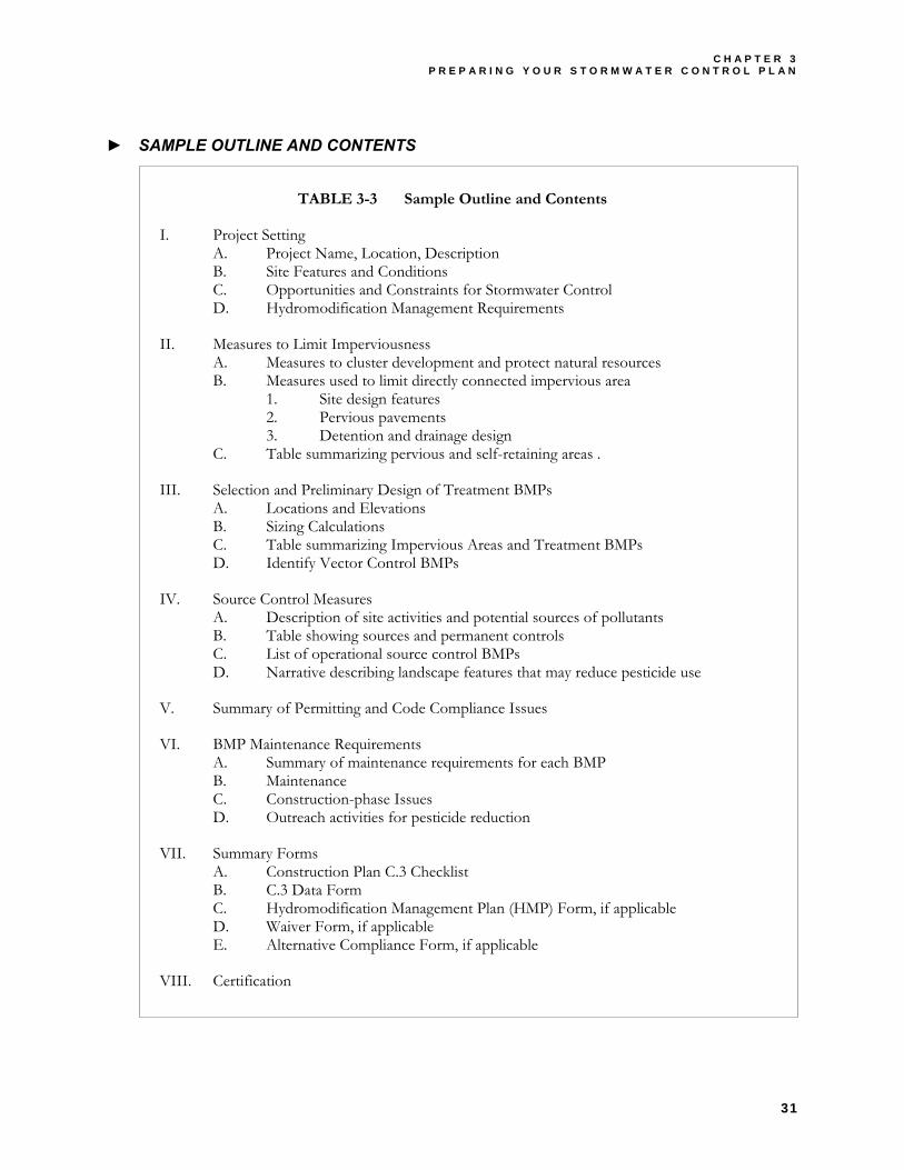
C H A P T E R 3 P R E P A R I N G Y O U R S T O R M W A T E R C O N T R O L P L A N
31
► SAMPLE OUTLINE AND CONTENTS
TABLE 3-3 Sample Outline and Contents
I. Project Setting A. Project Name, Location, Description B. Site Features and Conditions C. Opportunities and Constraints for Stormwater Control D. Hydromodification Management Requirements
II. Measures to Limit Imperviousness A. Measures to cluster development and protect natural resources B. Measures used to limit directly connected impervious area
1. Site design features 2. Pervious pavements 3. Detention and drainage design
C. Table summarizing pervious and self-retaining areas .
III. Selection and Preliminary Design of Treatment BMPs A. Locations and Elevations B. Sizing Calculations C. Table summarizing Impervious Areas and Treatment BMPs D. Identify Vector Control BMPs
IV. Source Control Measures A. Description of site activities and potential sources of pollutants B. Table showing sources and permanent controls C. List of operational source control BMPs D. Narrative describing landscape features that may reduce pesticide use
V. Summary of Permitting and Code Compliance Issues
VI. BMP Maintenance Requirements A. Summary of maintenance requirements for each BMP B. Maintenance C. Construction-phase Issues D. Outreach activities for pesticide reduction
VII. Summary Forms A. Construction Plan C.3 Checklist B. C.3 Data Form C. Hydromodification Management Plan (HMP) Form, if applicable D. Waiver Form, if applicable E. Alternative Compliance Form, if applicable
VIII. Certification

C H A P T E R 4 S T O R M W A T E R C O N T R O L & C E Q A
33
Chapter
4 4 STORMWATER CONTROL &
CEQA
Incorporating stormwater impacts and control measures into Initial Studies and Environmental Impact Reports
EQA – the California Environmental Quality Act – requires local jurisdictions to identify and evaluate the environmental impacts of their actions. Municipal actions subject to CEQA include discretionary approvals such as zoning decisions and use permits. The objectives of CEQA include disclosing to decision makers and the public significant environmental effects of
proposed activities, identifying ways to avoid or reduce adverse environmental impacts, and preventing environmental damage by requiring implementation of feasible alternatives or mitigation measures.
The City requires that you complete an Environmental Information Form as part of your application for planning and zoning review. Depending on the project scope, additional documentation may be required. Your Stormwater Control Plan contains information to be reviewed under CEQA.
The Planning Division will complete an Environmental Checklist and Initial Study for your project. Depending on the results of the Initial Study, the Planning Division may recommend a Negative Declaration or Mitigated Negative Declaration be issued for the project, or it may recommend that an Environmental Impact Report be prepared.
Further guidance on the CEQA process is available from the Planning Division and from the references and resources listed at the end of this Chapter.
The purpose of this chapter is to clarify how information in your Stormwater Control Plan will be used in the CEQA review process.
4.1 CEQA AND WATER QUALITY REGULATIONS
NPDES permit provision C.3.m states that when the City conducts environmental review of projects, it must evaluate water quality effects and identify appropriate mitigation measures.
The Governor’s Office of Planning and Research (OPR) recommends that CEQA lead agencies should integrate CEQA review with Federal, state, or local laws, regulations, or policies “to the fullest extent possible.” (CEQA Guidelines §15124). In 1998, OPR revised the example Environmental Checklist Form (CEQA Guidelines Appendix G) to more closely align with Federal and state laws and requirements, including those of the state’s Fish and Game Code, the Federal Clean Water Act, and the California Water Code. The City of Milpitas uses the OPR Environmental Checklist Form.
Specific questions on the Environmental Checklist Form connect the potential significance of project impacts with existing water-quality regulations. With the promulgation of the NPDES C.3 provisions, the RWQCB has, in effect, set more specific standards for what constitutes “substantial additional sources” of runoff pollutants.
C
C I T Y O F M I L P I T A S S T O R M W A T E R C . 3 G U I D E B O O K
34
4.2 THRESHOLDS OF SIGNIFICANCE
A threshold of significance can be defined as “a quantitative or qualitative standard, or set of criteria, pursuant to which the significance of an environmental effect may be determined.” (OPR 1994). Thresholds are not rigid or absolute—the significance of an activity depends on its specific location—but they do help Lead Agencies make consistent and well-supported determinations.
In most cases, the City of Milpitas will regard projects that exceed the thresholds in NPDES permit provision C.3.c to have potentially significant impacts due to increases in runoff pollutants. The thresholds and requirements are intended to address both cumulative and site-specific increases in runoff pollutants due to imperviousness.
A project may also have potentially significant impacts due to increases in runoff pollutants if the facility includes outdoor storage of materials or wastes or if it accommodates outdoor activities such as automotive or equipment repair. Examples include car washes, grocery stores, some restaurants, and corporation yards. The threshold of significance in this case is qualitative and requires project-specific assessment of the potential for pollutants generated on-site to reach storm drains.
► INCORPORATING MITIGATION MEASURES
The RWQCB’s C.3 provisions create a de facto threshold of significance for stormwater pollutant impacts; they also identify corresponding measures that can mitigate those impacts below the level of significance.
In general, the implementation of treatment BMPs that meet the numeric criteria in Provision C.3.d, as described in Chapter 5, will mitigate the effects of increased imperviousness on water quality to a level that is less than significant. Similarly, implementation of recommended source control BMPs for each identified source of potential pollutants will effectively mitigate the creation of these additional sources.
► STORMWATER IMPACTS AND THE CEQA PROCESS
In summary, if the amount of impervious area created by a project is less than the threshold identified in NPDES permit provision C.3.c, and there are no significant new sources of runoff pollutants created by the project, the relevant questions on the Initial Study Checklist can be answered “less than significant impact.”
If a project is required to implement treatment BMPs pursuant to NPDES permit C.3.c, the potential for significant stormwater impacts should be noted on the Environmental Information Form. This can be done by checking “yes” in response to Question 26 (Change in ocean, bay, lake, stream, or ground water quality or quantity or alteration of existing drainage patterns) and referencing the Stormwater Control Plan for the project.
If the Stormwater Control Plan for the project meets the criteria in NPDES permit C.3.d and incorporates recommended source control measures for each potential source of pollutants identified, then the relevant questions regarding stormwater quality in the Initial Study Checklist can, in most cases, be answered “less than significant with mitigation incorporation.” The City’s initial study will note the specific source control and treatment BMPs incorporated and will reference the Stormwater Control Plan.
In some cases, a project may be below the threshold defined in Provision C.3.c but still create a significant new source of potential runoff pollutants. This might occur, for example, with an application for a use permit for a new business (say, a car wash) on an already fully developed (and impervious) site. In these cases,
C H A P T E R 4 S T O R M W A T E R C O N T R O L & C E Q A
35
potential impacts can be mitigated through incorporation of appropriate permanent and operational source control BMPs.
Note that source control or treatment BMPs must be maintained for the life of the project to effectively mitigate the potential environmental effect. Similarly, operational BMPs must be implemented thoroughly and consistently to be effective mitigations. Monitoring of permanent BMPs will be accomplished through the City’s BMP Operation and Maintenance Verification Program (Chapter 6). The City also inspects industrial and commercial sites to verify consistent use of operational BMPs.
References and Resources • RWQCB Order 01-119, Provision C.3.m • California Environmental Quality Act Statutes (Public Resources Code §21000 et seq.) • Governor’s Office of Planning and Research • City of Milpitas Environmental Information Form • City of Milpitas Environmental Impact Assessment Form (Initial Study Checklist) • CEQA Deskbook (Bass, et. al., 2001) • SCVURPPP C.3 Stormwater Handbook, Attachment II-7: CEQA Guidance

C H A P T E R 5 T E C H N I C A L R E Q U I R E M E N T S
37
Chapter
5 5 TECHNICAL REQUIREMENTS
Technical guidance for designing self-detaining areas and sizing treatment BMPs
our Stormwater Control Plan (Chapter 3), to be submitted with your planning and zoning application, must show the locations, sizes, and types of treatment BMPs. Your Stormwater Control Plan must also include calculations showing your treatment BMPs meet the minimum sizing criteria in the stormwater NPDES permit.
Construction plans for the project must be consistent with the approved Stormwater Control Plan. During plan check, local agency staff will review the details of how your drainage and BMPs are to be constructed and will verify that they meet the numeric criteria in the RWQCB’s NPDES permit.
This chapter has three parts.
The first part explains the applicable technical criteria, interprets the RWQCB’s aims in establishing the criteria, and refers to the documents, studies, and rationales on which the criteria are based. The first part also provides some recommendations for selecting among the alternative sizing criteria allowed by the RWQCB.
The second part provides guidance for designing and documenting self-retaining areas and treatment BMPs. The recommended process aims to maximize the use of self-retaining areas and integrated/distributed BMPs while allowing multiple options and flexibility to the designer. The process involves step-by-step completion of a table that will facilitate plan checking. This table should be submitted as part of your Stormwater Control Plan. See Chapter 3.
The third part provides some sample preliminary designs for treatment BMPs, design recommendations and tips, and references to available design manuals.
5.1 PART 1: STORMWATER CONTROL TECHNICAL CRITERIA
The NPDES C.3. provisions require a complex, multifaceted approach to on-site stormwater control. In effect, project applicants must implement several different, independent measures to control stormwater pollutants, and each of these measures must independently meet a “maximum extent practicable” standard.
Specifically, applicants must:
♦ Control pollutant sources to the maximum extent practicable. ♦ Limit pesticide use and potential impacts to the maximum extent practicable. ♦ Implement site design and landscape features which reduce runoff pollutants to the maximum extent
practicable.
Most measures of “maximum extent practicable” are qualitative and are based on professional judgment and current practices. However, the permit includes numeric criteria for the design of treatment BMPs. These numeric criteria are intended to insure that the treatment BMPs are adequately designed to remove a significant portion of pollutants in runoff.
Y
C I T Y O F M I L P I T A S S T O R M W A T E R C . 3 G U I D E B O O K
38
Permit Provision C.3.f requires limits on peak runoff flow and peak runoff volume. The Hydromodification Management Plan (HMP), adopted by the RWQCB in July 2005, identifies geographic areas where peak runoff flow and volume must be controlled (i.e. post-project runoff must not exceed estimated pre-project rates or durations). HMP limits on runoff peak flow and volume are independent of the treatment requirements to achieve pollutant removal. Chapter 8 contains additional information on HMP requirements.
All projects must control runoff peak flow and volume to the “maximum extent practicable” and must also incorporate treatment BMPs that are sized to meet the minimum numeric criteria.
Typically, BMPs designed for flow control will attempt to detain enough runoff to avoid increases in the peak and duration of flows that result from approximately 10% of a 2-year storm up to a 10-year storm.
BMPs for pollutant removal are designed to treat runoff from storms up to a 1- to 2-year recurrence interval. However, they are also designed to provide longer detention (e.g., 40 hours) to provide plenty of time for pollutants to settle out.
Basins or ponds can achieve detention and retention for flow control and also meet the detention time required to insure effective pollutant removal, but the design may require multiple discharge points at different depths.
► LIMITS ON THE USE OF INFILTRATION
RWQCB permit Provision C.3.i requires a 10-foot vertical separation between the bottom of any “treatment BMPs that function primarily as infiltration devices” and the “seasonal high groundwater mark.” In addition, these BMPs should not serve work areas, including automotive shops, car washes, fleet storage, nurseries, or other areas that may be significant sources of pollutants.
Soils must be in Hydrologic Soil Groups “A” or “B” as identified by the NRCS. In many areas of Milpitas, high groundwater and impermeable soils preclude the use of infiltration. In some areas east of I-680, steep slopes and geological instability make infiltration inadvisable.
SCVURPPP and the Santa Clara Valley Water District have prepared guidelines for the use of infiltration devices. SCVURPPP’s guidelines are summarized in TABLE 5-1 on page 39. Proposals to use infiltration devices that do not conform to these criteria should be reviewed by the Santa Clara Valley Water District.
► NUMERIC CRITERIA
The RWQCB permit assumes that treatment BMPs can be classified as relying either on detention and infiltration (e.g. detention basins, dry wells, or constructed wetlands) or on filtration (e.g., sand filters). The permit specifies volume-based criteria for those BMPs relying on infiltration and detention and flow-based criteria for BMPs relying on filtration.
► VOLUME-BASED NUMERIC CRITERIA
The RWQCB permit specifies two alternative methods for calculating water quality volume, the volume of water that must be detained for a BMP to meet the “maximum extent practicable” criterion. The first method is stated in the book Urban Runoff Quality Management (Water Environment Federation Manual of Practice No. 23; ASCE Manual and Report on Engineering Practice No. 87, 1998) and is referred to as the WEF Method.
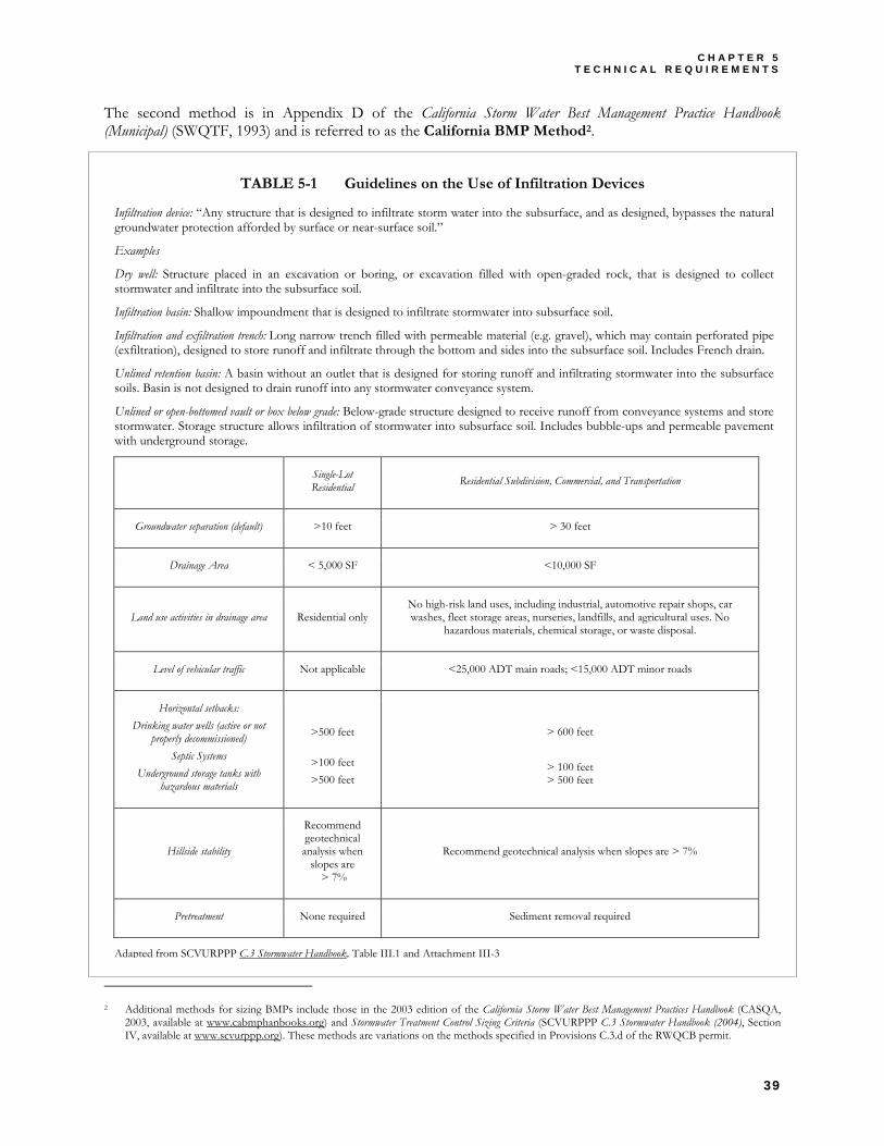
C H A P T E R 5 T E C H N I C A L R E Q U I R E M E N T S
39
The second method is in Appendix D of the California Storm Water Best Management Practice Handbook (Municipal) (SWQTF, 1993) and is referred to as the California BMP Method2.
TABLE 5-1 Guidelines on the Use of Infiltration Devices
2 Additional methods for sizing BMPs include those in the 2003 edition of the California Storm Water Best Management Practices Handbook (CASQA,
2003, available at www.cabmphanbooks.org) and Stormwater Treatment Control Sizing Criteria (SCVURPPP C.3 Stormwater Handbook (2004), Section IV, available at www.scvurppp.org). These methods are variations on the methods specified in Provisions C.3.d of the RWQCB permit.
Infiltration device: “Any structure that is designed to infiltrate storm water into the subsurface, and as designed, bypasses the natural groundwater protection afforded by surface or near-surface soil.”
Examples
Dry well: Structure placed in an excavation or boring, or excavation filled with open-graded rock, that is designed to collect stormwater and infiltrate into the subsurface soil.
Infiltration basin: Shallow impoundment that is designed to infiltrate stormwater into subsurface soil.
Infiltration and exfiltration trench: Long narrow trench filled with permeable material (e.g. gravel), which may contain perforated pipe (exfiltration), designed to store runoff and infiltrate through the bottom and sides into the subsurface soil. Includes French drain.
Unlined retention basin: A basin without an outlet that is designed for storing runoff and infiltrating stormwater into the subsurface soils. Basin is not designed to drain runoff into any stormwater conveyance system.
Unlined or open-bottomed vault or box below grade: Below-grade structure designed to receive runoff from conveyance systems and store stormwater. Storage structure allows infiltration of stormwater into subsurface soil. Includes bubble-ups and permeable pavement with underground storage.
Single-Lot Residential Residential Subdivision, Commercial, and Transportation
Groundwater separation (default) >10 feet > 30 feet
Drainage Area < 5,000 SF <10,000 SF
Land use activities in drainage area Residential only No high-risk land uses, including industrial, automotive repair shops, car washes, fleet storage areas, nurseries, landfills, and agricultural uses. No
hazardous materials, chemical storage, or waste disposal.
Level of vehicular traffic Not applicable <25,000 ADT main roads; <15,000 ADT minor roads
Horizontal setbacks: Drinking water wells (active or not
properly decommissioned) Septic Systems
Underground storage tanks with hazardous materials
>500 feet
>100 feet >500 feet
> 600 feet
> 100 feet > 500 feet
Hillside stability
Recommend geotechnical analysis when
slopes are > 7%
Recommend geotechnical analysis when slopes are > 7%
Pretreatment None required Sediment removal required
Adapted from SCVURPPP C.3 Stormwater Handbook, Table III.1 and Attachment III-3
C I T Y O F M I L P I T A S S T O R M W A T E R C . 3 G U I D E B O O K
40
The two methods are based on the same rainfall data and hydrological methodology, and they tend to yield similar results. The methods differ in some aspects of their practical application.
Both methods use an analysis of long-term rainfall data to identify a design storm. Eighty percent of total annual runoff is produced by storms this size and smaller. In the Milpitas area, the design storm totals about one-half inch of rainfall.
The WEF method requires that the designer specify a drawdown time of 12, 24, or 48 hours. Longer drawdown times require larger BMP volumes (because of the potential for back-to-back storms). Although the permit does not specify a drawdown time, the longer time (48 hours) has been recommended by SCVURPPP consultants. Sediments from the Bay Area’s fine-grained soils require a relatively long time to settle out. The California BMP method uses a fixed drawdown time of 40 hours.
The WEF method is based on 80% capture of average annual runoff. The California BMP method allows the designer to select a capture ratio; however, the RWQCB permit specifies that an 80% capture ratio be used.
The WEF method requires estimation of a mean storm precipitation volume. This can be based on local rainfall data. The analysis is conducted by taking periodic (e.g. hourly) rain gauge data, identifying distinct storms, calculating the total rainfall depth of each, and taking an average. Analysis of over 50 years of data at the San Jose Airport gauge resulted in a mean storm size of 0.512 inches. The California BMP method incorporates this analysis into a nomograph for the specific locality.
The WEF method requires calculation of a composite (weighted) runoff coefficient for the area that is tributary to the BMP being designed. The method provides a formula for calculating the runoff coefficient from the “watershed imperviousness ratio,” or the percent total imperviousness.
Similarly, the California BMP method requires estimation of “the percentage of impervious area directly connected to the storm drain system. DCIA is defined as the area covered by pavement, building, and other impervious surfaces which drain directly into a storm drain without first flowing across pervious areas (e.g. lawns).” Conceptually, the tributary drainage is divided into areas that are either wholly pervious or wholly impervious. (In fact, the input parameters to the STORM model used to generate the California BMP curves assumed 0.9 for impervious surfaces and 0.15 for pervious surfaces.)
► FLOW-BASED CRITERIA
The RWQCB permit allows three alternatives for calculating the peak flow rate that a continuous-flow BMP (e.g., a sand filter without an upstream detention area) must be able to accommodate.
All three use the rational method to calculate peak flows:
Q = C i A
where
Q = Peak flow rate C = Runoff coefficient (percent imperviousness) i = Rainfall intensity A = Tributary area
The difference between the three methods is in the calculation of the rainfall intensity, i.
C H A P T E R 5 T E C H N I C A L R E Q U I R E M E N T S
41
The three alternatives are intensity-duration-frequency (IDF), percentile rainfall intensity, and 0.2 inches/hour.
The intensity-duration-frequency alternative requires that a time of concentration (Tc) be calculated for the tributary area. Calculation of a time of concentration is based on analysis of the time required for a hypothetical drop of water to flow from the furthest point of the watershed, overland and/or through pipes, to the BMP. Once Tc is determined, a corresponding i can be found from graphs of rainfall intensity vs. time from start of storm. These graphs can be found in the Santa Clara County Drainage Manual. The RWQCB permit specifies use of the rainfall intensity corresponding to a 50-year storm.
The percentile rainfall intensity alternative is based on ranking the intensity of rainfall from storms over a relatively long record. The RWQCB permit specifies that the intensity of the 85th percentile storm be multiplied by two. The result for the local area (San Jose) is 0.17 inches per hour.
The 0.2 inches/hour alternative simply specifies the required i : 0.2 inches per hour.
In summary, if the designer uses either the percentile rainfall intensity alternative or the 0.2 inches/hour alternative to size a flow-based BMP, he or she need only specify the tributary area and its percent imperviousness.
If the intensity-duration-frequency method is used, the designer must calculate Tc. Because calculation of Tc is complex and uncertain, and because the peak flow rate can be relatively sensitive to Tc, the City discourages applicants from using this method. It is most applicable to larger sites with overland drainage and relatively little impervious cover; however, the use of flow-based BMPs (such as sand filters) is inappropriate in such sites because of the potential for blinding the filter with fine sediments.
References and Resources • RWQCB Order No. 01-119 (Stormwater NPDES Permit Amendments) • California Stormwater Best Management Practice Handbooks (SWQTF, 1993). • California Stormwater Best Management Practice Handbooks (CASQA, 2003). • SCVURPPP C.3 Stormwater Handbook (SCVURPPP, 2004). Section IV. • Urban Runoff Quality Management (WEF/ASCE, 1998) • Hydrology Handbook, Second Edition (ASCE, 1996) • Low Impact Development Design Strategies: An Integrated Approach (Maryland, 2001)
5.2 PART 2: BMP DESIGN AND DOCUMENTATION
There are two general approaches to managing site runoff.
The integrated/distributed BMP approach emphasizes “disconnection” of impervious areas from the drainage system and detention, infiltration, and treatment of runoff throughout the site. Detention and infiltration areas are sized and shaped to fit the available space. Maintenance requirements may be little more than what is required for normal landscaping. Low Impact Development, pioneered in Prince George’s County, Maryland, exemplifies the integrated/distributed approach.
The conventional BMP approach emphasizes the design of facilities that can retain, detain, and treat runoff from large portions of the site or from the whole site. These BMPs typically serve a mix of impervious, pervious, and partially pervious portions of the site and are generally more dependent on precise engineering and frequent maintenance. Facilities are sized by engineering formulas to insure that a targeted proportion of sediment particles either settle or are filtered out of the runoff flow. The WEF/ASCE Manual of Practice, Urban Runoff Quality Management, exemplifies the conventional BMP approach.
C I T Y O F M I L P I T A S S T O R M W A T E R C . 3 G U I D E B O O K
42
The two approaches are not exclusive and can be combined within one site.
In general, smaller BMPs distributed throughout the site look better and may require less area be dedicated to stormwater controls. In addition, integrated/distributed BMPs are less likely to fail and may be less likely to harbor mosquitoes or other vectors.
However, integrated/distributed BMPs typically require a more complex drainage design, and demonstrating compliance with C.3 requirements for stormwater treatment is somewhat more difficult with integrated/distributed BMPs than with conventional BMPs. It is necessary to account for the impervious area treated by each integrated/distributed BMP and show that the chosen suite of integrated/distributed BMPs will retain and treat the required proportion of total site runoff effectively.
Designs using integrated/distributed BMPs are able to distribute runoff storage throughout the site. By incorporating small detention areas and BMPs into the flow path, these designs tend to increase the time of concentration of flow, reducing peak discharges and volumes.
► RECOMMENDED PROCEDURE FOR DESIGN AND DOCUMENTATION
The City of Milpitas has developed the following recommended procedure for selecting and documenting self-detaining areas, integrated/distributed BMPs, and conventional BMPs.
The procedure maximizes the use of self-retaining areas and integrated/distributed BMPs and anticipates that, in many cases, conventional BMPs such as detention basins and media filters may not be necessary to achieve compliance with the C.3 provisions. Where conventional BMPs are required, the procedure minimizes their size3.
The procedure requires careful delineation of pervious areas and impervious areas (including roofs) throughout the site. The designer must, in effect, account for the runoff produced by each delineated area during the design storm. The procedure uses sizing factors to simplify design and arranges documentation of BMP sizing in a consistent format for presentation and review.
The recommended design procedure is intended to facilitate, not substitute for, creative interplay among the site design, landscape design, and drainage design. Several iterations may be needed to find the combination of self-retaining areas, integrated/distributed BMPs, and conventional BMPs that provides the optimal aesthetics, circulation, and use of available area for your site.
A spreadsheet template, in Microsoft Excel format, is provided for making calculations and presenting your submittal. See Appendix E.
► SELECTING AND DOCUMENTING SELF-RETAINING AREAS AND BMPS
The required size of treatment BMPs is proportionate to the total connected tributary area and the weighted imperviousness of that area. The best way to reduce the number and size of treatment BMPs is to disconnect portions of the tributary area and remove these disconnected areas from the sizing calculation.
3 The publication Using Site Design Techniques to Meet Development Standards for Stormwater Quality, A companion Document to Start at the Source (BASMAA,
May 2003, 14 pp. available at www.scvurppp.org) suggests using self-retaining areas to reduce the size of detention basins and other conventional BMPs. The Milpitas C.3 Guidebook approach maximizes self retaining areas first, then maximizes the use of integrated/distributed BMPs, and incorporates conventional BMPs only as a last resort.
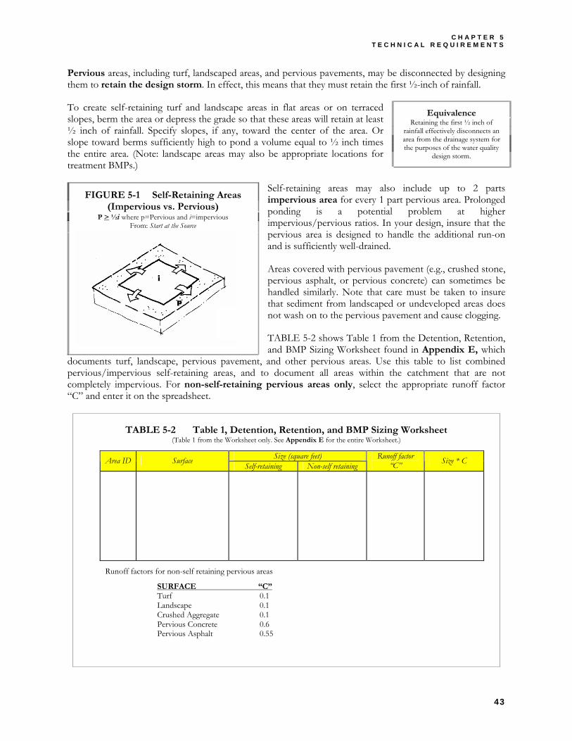
C H A P T E R 5 T E C H N I C A L R E Q U I R E M E N T S
43
Pervious areas, including turf, landscaped areas, and pervious pavements, may be disconnected by designing them to retain the design storm. In effect, this means that they must retain the first ½-inch of rainfall.
To create self-retaining turf and landscape areas in flat areas or on terraced slopes, berm the area or depress the grade so that these areas will retain at least ½ inch of rainfall. Specify slopes, if any, toward the center of the area. Or slope toward berms sufficiently high to pond a volume equal to ½ inch times the entire area. (Note: landscape areas may also be appropriate locations for treatment BMPs.)
Self-retaining areas may also include up to 2 parts impervious area for every 1 part pervious area. Prolonged ponding is a potential problem at higher impervious/pervious ratios. In your design, insure that the pervious area is designed to handle the additional run-on and is sufficiently well-drained.
Areas covered with pervious pavement (e.g., crushed stone, pervious asphalt, or pervious concrete) can sometimes be handled similarly. Note that care must be taken to insure that sediment from landscaped or undeveloped areas does not wash on to the pervious pavement and cause clogging.
TABLE 5-2 shows Table 1 from the Detention, Retention, and BMP Sizing Worksheet found in Appendix E, which
documents turf, landscape, pervious pavement, and other pervious areas. Use this table to list combined pervious/impervious self-retaining areas, and to document all areas within the catchment that are not completely impervious. For non-self-retaining pervious areas only, select the appropriate runoff factor “C” and enter it on the spreadsheet.
TABLE 5-2 Table 1, Detention, Retention, and BMP Sizing Worksheet (Table 1 from the Worksheet only. See Appendix E for the entire Worksheet.)
Equivalence Retaining the first ½ inch of
rainfall effectively disconnects an area from the drainage system for the purposes of the water quality
design storm.
FIGURE 5-1 Self-Retaining Areas (Impervious vs. Pervious)
P > ½i where p=Pervious and i=impervious From: Start at the Source
Size (square feet) Area ID Surface Self-retaining Non-self retaining Runoff factor
“C” Size * C
Runoff factors for non-self retaining pervious areas
SURFACE “C” Turf 0.1 Landscape 0.1 Crushed Aggregate 0.1 Pervious Concrete 0.6 Pervious Asphalt 0.55
C I T Y O F M I L P I T A S S T O R M W A T E R C . 3 G U I D E B O O K
44
► ROUTE RUNOFF TO INTEGRATED/DISTRIBUTED BMPS
Runoff from impervious areas (roofs and impervious pavements) can be effectively disconnected by routing runoff to planter boxes, bioretention areas, and other BMPs that are integrated into the landscaping. Simple factors may be used to size these integrated/distributed BMPs.
To select integrated/distributed BMPs, follow this procedure:
1. Determine the impervious surface area that will drain to the BMP. Where possible, distribute drainage from opposite sides of driveways, opposite sides of buildings, and from different sections of parking lots to separate small BMPs located within landscaped areas. Individual vegetated filters, planter boxes and sand filters are best designed to serve impervious areas up to 15,000 square feet.
2. Select a BMP type and apply the corresponding sizing factor to determine the required surface are of the BMP.
3. Check that the required surface area can be accommodated within your site design, and redesign if necessary.
Avoid routing runoff from landscaped and other pervious areas to integrated/distributed BMPs, particularly where runoff may carry fine sediments. Instead, design these landscaped areas to be “self-retaining,” i.e. to retain the design storm and to drain higher flows off-site.
4. List each non-self-retaining area within the catchment.
5. State which non-self-retaining areas drain to each integrated/ distributed BMP, and estimate the imperviousness of each remaining non-self-detaining area.
6. Use this information to size any required conventional BMPs.
TABLE 5-3 on page 45 shows Table 2 from the Detention, Retention, and BMP Sizing Worksheet found in Appendix E. It provides a way to document all impervious area within the catchment, document selection of integrated/distributed BMPs, and calculate of the required minimum surface area of each BMP.
Design requirements and details for some integrated/distributed BMPs are described in the BMP Gallery beginning on page 48.
► SIZING CONVENTIONAL BMPS IF NECESSARY
If drainage from all impervious areas can be routed to self-retaining areas or integrated/distributed BMPs, then no conventional BMPs are required. If some of the catchment area still produces runoff, conventional BMPs are necessary, but the required size of the BMPs will be minimized.
The runoff from the remaining area in each catchment—pervious areas that are not self-retaining, plus impervious areas that are not served by integrated/distributed BMPs—must be routed to a conventional BMP.
As described in the RWQCB permit, treatment BMPs are either volume-based or flow-based. For some volume-based conventional BMPs (e.g., detention basins and constructed wetlands) discharge is controlled by the size of the outlet orifice. Note that suitable outlet orifices cannot be designed for small flows. For this
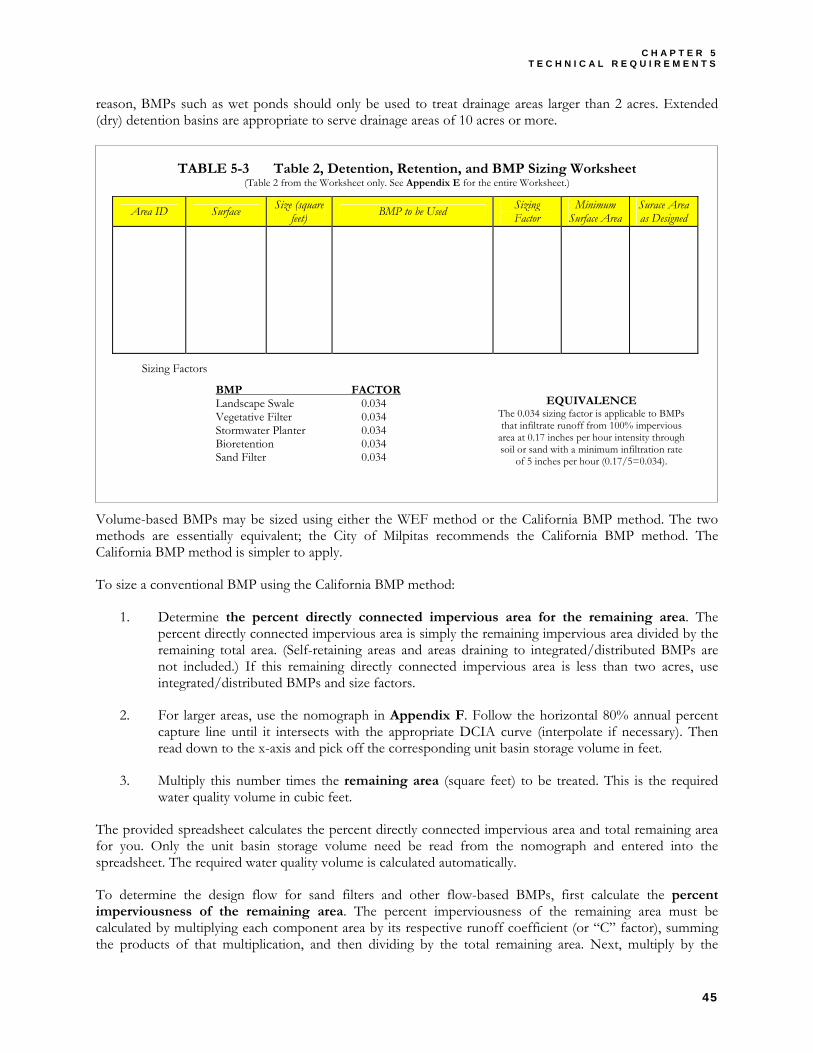
C H A P T E R 5 T E C H N I C A L R E Q U I R E M E N T S
45
reason, BMPs such as wet ponds should only be used to treat drainage areas larger than 2 acres. Extended (dry) detention basins are appropriate to serve drainage areas of 10 acres or more.
TABLE 5-3 Table 2, Detention, Retention, and BMP Sizing Worksheet (Table 2 from the Worksheet only. See Appendix E for the entire Worksheet.)
Volume-based BMPs may be sized using either the WEF method or the California BMP method. The two methods are essentially equivalent; the City of Milpitas recommends the California BMP method. The California BMP method is simpler to apply.
To size a conventional BMP using the California BMP method:
1. Determine the percent directly connected impervious area for the remaining area. The percent directly connected impervious area is simply the remaining impervious area divided by the remaining total area. (Self-retaining areas and areas draining to integrated/distributed BMPs are not included.) If this remaining directly connected impervious area is less than two acres, use integrated/distributed BMPs and size factors.
2. For larger areas, use the nomograph in Appendix F. Follow the horizontal 80% annual percent capture line until it intersects with the appropriate DCIA curve (interpolate if necessary). Then read down to the x-axis and pick off the corresponding unit basin storage volume in feet.
3. Multiply this number times the remaining area (square feet) to be treated. This is the required water quality volume in cubic feet.
The provided spreadsheet calculates the percent directly connected impervious area and total remaining area for you. Only the unit basin storage volume need be read from the nomograph and entered into the spreadsheet. The required water quality volume is calculated automatically.
To determine the design flow for sand filters and other flow-based BMPs, first calculate the percent imperviousness of the remaining area. The percent imperviousness of the remaining area must be calculated by multiplying each component area by its respective runoff coefficient (or “C” factor), summing the products of that multiplication, and then dividing by the total remaining area. Next, multiply by the
Area ID Surface Size (square feet) BMP to be Used Sizing
Factor Minimum
Surface Area Surace Area as Designed
Sizing Factors
BMP FACTOR Landscape Swale 0.034 Vegetative Filter 0.034 Stormwater Planter 0.034 Bioretention 0.034 Sand Filter 0.034
EQUIVALENCE The 0.034 sizing factor is applicable to BMPs that infiltrate runoff from 100% impervious
area at 0.17 inches per hour intensity through soil or sand with a minimum infiltration rate
of 5 inches per hour (0.17/5=0.034).
C I T Y O F M I L P I T A S S T O R M W A T E R C . 3 G U I D E B O O K
46
appropriate rainfall intensity (0.2 inches/hour). Divide by 43,200 to get the design minimum flow rate in cubic feet per second.
References and Resources • Appendix E, Detention, Retention, and BMP Sizing Worksheet • Appendix F, California BMP Method Sizing Worksheet • Appendix D, Example Stormwater Control Plans • RWQCB Order 01-119, Provisions C.3.d and C.3.i. • Hydrology Handbook, Second Edition (ASCE 1996) • Highway Design Manual (California Department of Transportation, 2001). Chapter 8. • Portland Stormwater Management Manual (City of Portland, 2002). • City of Milpitas Soils Maps. • City of Milpitas Groundwater Infiltration Evaluation. • USDA SCS Technical Release TR55, Appendix A: Soil Types
5.3 PART 3: DESIGN HELP
► SITE DESIGN AND SELF-RETAINING AREAS
Start at the Source: Design Guidance Manual for Stormwater Quality Protection, published in 1999 by the Bay Area Stormwater Management Agencies Association (BASMAA), is an updated version of a manual first published in 1997. The 1999 edition covers planning and zoning, site design, and drainage systems. The manual also includes some details for site design, pervious pavements and landscaping, and BMPs.
Start at the Source is an excellent general design guide and is best consulted at the beginning of the site design process.
► GALLERY OF INTEGRATED/DISTRIBUTED BMPS
State and local governments elsewhere in the U.S. have developed more specific design details for BMPs. Portland, Oregon, developed the “simplified” design, using sizing factors, that is described above for selecting and sizing integrated/distributed BMPs. The City of Milpitas has selected and adapted some of Portland’s design details. These details may be adapted for use with the following integrated/distributed BMPs:
♦ Landscape Swales ♦ Vegetative Filters ♦ Stormwater Planters ♦ Landscape Infiltration ♦ Sand Filters
In addition, the City of Milpitas encourages the use of bioretention areas. A typical design (excerpted from Prince Georges County, 1999) is included in the BMP Gallery. Designers should also consult USEPA’s Storm Water Technology Fact Sheet: Bioretention (EPA 832-F-99-012, 1999).
Designs for bioretention areas and swales, including AutoCad drawings, can be accessed through the Low Impact Development Center. Most of these designs can be adapted to areas with low-permeability soils, shallow groundwater, or steep slopes by incorporating an impermeable liner and an underdrain system composed of drain rock and perforated drain pipe. Because the BMP may require 1' to 4' difference in elevation between the inlet and outlet, it is advisable to consider the requirements for these BMPs when preparing site plans and designing grading and drainage for the site.
C H A P T E R 5 T E C H N I C A L R E Q U I R E M E N T S
47
► DESIGN OF CONVENTIONAL BMPS
For guidance on designing conventional BMPs, see Urban Runoff Quality Management (WEF/ASCE, 1998) and the California Stormwater BMP Handbooks (CASQA, 2003).
► VECTOR CONTROL AND OTHER CONSIDERATIONS FOR BMP DESIGN
The following notes and design advice have been compiled from observations and experience with the design of BMPs for development sites and from the California Department of Health Services’ guidance for controlling mosquitoes in stormwater treatment devices. Review these notes and incorporate applicable items into your Stormwater Control Plan. This will help ensure that these concerns are addressed in the final design and construction permit review process.
BMPs will require 1' to 4' or more head (difference in elevation between the inlet and outlet). Note that in some cases BMP outlets can be piped to underground storm drain systems. Wherever possible, locate and design the BMP along the hydraulic grade line of the site drainage. Vaults, pumps, and sumps are discouraged because they reduce reliability, increase maintenance, and create potential vector problems.
Sand filters work best when they serve 100% impervious areas and the potential for fine sediment entering runoff is minimal (e.g. roof drainage). Sand filters combined with pre-treatment pools and vaults (i.e. multi-chambered treatment trains) are discouraged.
To avoid mosquito problems, the California Department of Health Services recommends that dry basins (extended detention basins) should be designed to drain completely within 72 hours of a rainfall.
Large, shallow basins with gentle side slopes are easiest to maintain and may be designed as multi-use facilities (e.g. playing fields or landscape). Design extended detention basins with a sloped bottom channel to promote complete drainage. Consider over-excavating and replacing the detention-basin bottom with permeable soil. Consider an underdrain to promote healthy turf and drainage.
Design and construct inlets and outlets to avoid differential settlement that can cause shallow, persistent puddles. Riprap or rock may be required to dissipate energy at inlets and outlets, but can collect standing water and create mosquito problems. Use cemented rock or insure that any areas where water may temporarily pool are well-drained.
Underground vaults and other storage or settlement devices, deflection separators, oil/water separators, and drain inlet inserts are strongly discouraged. If these devices are allowed they should include provisions to seal the device against mosquito access and also include suitable access doors and hatches to allow for frequent inspections and maintenance.
References and Resources • Portland Stormwater Management Manual (City of Portland, 2002). • California Stormwater Best Management Practice Handbooks (CASQA, 2003). • Low Impact Development Design Strategies: An Integrated Approach (Maryland, 2001) • Stormwater Management Manual for Western Washington (Washington, 2001) • Urban Runoff Quality Management (WEF/ASCE, 1998) • Low Impact Development Center • California Department of Health Services, Vector-Borne Disease Section. A Three-Year Assessment of Vector
Production in Structural Best Management Practices in Southern California. June 2002. 49 pp. • California Department of Health Services, Vector-Borne Disease Section. A Preliminary Assessment of Design
Critieria for Vector Prevention in Structural Best Management Practices in Southern California. June 2001(a). 50 pp. • Metzger, Marco E. Managing Mosquitoes in Stormwater Treatment Devices. University of California, Division of
Agriculture and Natural Resources. ANR Publication 8125. January 2004. 11 pp. http://anrcatalog.ucdavis.edu

C I T Y O F M I L P I T A S S T O R M W A T E R C . 3 G U I D E B O O K
48
5.4 BMP GALLERY
The BMP designs on the following pages are intended for use with the sizing factors in Table 5-3. The designs are provided to assist you with developing a Stormwater Control Plan. More specific detailed drawings, showing construction materials and methods to be used, plumbing connections, etc., will be required with your application for a building permit. Some of these requirements appear in Appendix G. Check with the City of Milpitas Building Department for requirements that apply to your project.
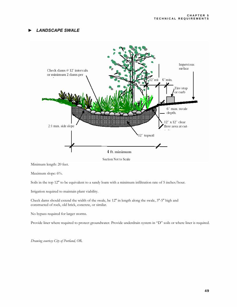
C H A P T E R 5 T E C H N I C A L R E Q U I R E M E N T S
49
► LANDSCAPE SWALE
Minimum length: 20 feet.
Maximum slope: 6%.
Soils in the top 12″ to be equivalent to a sandy loam with a minimum infiltration rate of 5 inches/hour.
Irrigation required to maintain plant viability.
Check dams should extend the width of the swale, be 12″ in length along the swale, 3″-5″ high and constructed of rock, old brick, concrete, or similar.
No bypass required for larger storms.
Provide liner where required to protect groundwater. Provide underdrain system in “D” soils or where liner is required.
Drawing courtesy City of Portland, OR.
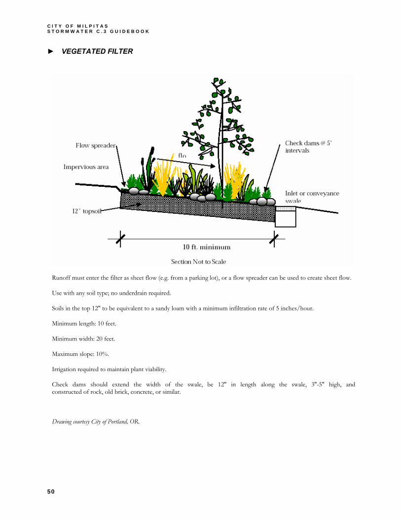
C I T Y O F M I L P I T A S S T O R M W A T E R C . 3 G U I D E B O O K
50
► VEGETATED FILTER
Runoff must enter the filter as sheet flow (e.g. from a parking lot), or a flow spreader can be used to create sheet flow.
Use with any soil type; no underdrain required.
Soils in the top 12″ to be equivalent to a sandy loam with a minimum infiltration rate of 5 inches/hour.
Minimum length: 10 feet.
Minimum width: 20 feet.
Maximum slope: 10%.
Irrigation required to maintain plant viability.
Check dams should extend the width of the swale, be 12″ in length along the swale, 3″-5″ high, and constructed of rock, old brick, concrete, or similar.
Drawing courtesy City of Portland, OR.

C H A P T E R 5 T E C H N I C A L R E Q U I R E M E N T S
51
► STORMWATER PLANTER
Can be used in any soil type (A,B,C,D). Can be used adjacent to building and within setback area.
Sandy loam topsoil to have a minimum infiltration rate of 5 inches/hour.
Minimum width: 18″.
Minimum length: none.
May be constructed of concrete, stone, or other durable material. Monolithic precast concrete recommended.
Irrigation required to maintain plant viability.
Install filter fabric between soil and gravel underdrain and around perforated pipe.
Size overflow trap for building code design storm; set trap below top of box.
Planter wall set against building should be higher to avoid overflow to that side.
Drawing courtesy City of Portland, OR.

C I T Y O F M I L P I T A S S T O R M W A T E R C . 3 G U I D E B O O K
52
► SAND FILTER
Can be used in any soil type (A,B,C,D). Sand to have a minimum infiltration rate of 5 inches/hour.
Can be used adjacent to building and within setback area.
Can be used above or below grade.
Install filter fabric between soil and gravel underdrain and around perforated pipe.
Size overflow trap for building code design storm; set trap below top of box.
Planter wall set against building should be higher to avoid overflow to that side.
Drawing courtesy City of Portland, OR.
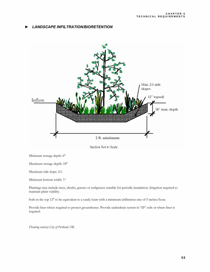
C H A P T E R 5 T E C H N I C A L R E Q U I R E M E N T S
53
► LANDSCAPE INFILTRATION/BIORETENTION
Minimum storage depth: 6″
Maximum storage depth: 18″
Maximum side slope: 2:1.
Minimum bottom width: 3 '
Plantings may include trees, shrubs, grasses or turfgrasses suitable for periodic inundation. Irrigation required to maintain plant viability.
Soils in the top 12″ to be equivalent to a sandy loam with a minimum infiltration rate of 5 inches/hour.
Provide liner where required to protect groundwater. Provide underdrain system in “D” soils or where liner is required.
Drawing courtesy City of Portland, OR.
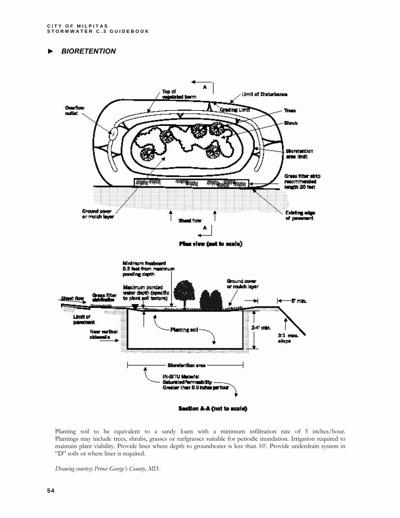
C I T Y O F M I L P I T A S S T O R M W A T E R C . 3 G U I D E B O O K
54
► BIORETENTION
Planting soil to be equivalent to a sandy loam with a minimum infiltration rate of 5 inches/hour.Plantings may include trees, shrubs, grasses or turfgrasses suitable for periodic inundation. Irrigation required to maintain plant viability. Provide liner where depth to groundwater is less than 10’. Provide underdrain system in “D” soils or where liner is required.
Drawing courtesy Prince George’s County, MD.
C H A P T E R 6 B M P M A I N T E N A N C E
55
Chapter
6 6 BMP MAINTENANCE
Identify the maintenance needs for the treatment BMPs on your site.
reatment BMPs must be regularly maintained to insure that they continue to be effective and that they do not cause flooding, harbor vectors, or otherwise cause a nuisance.
BMP maintenance is the responsibility of the property owner.
NPDES Permit Provision C.3.e requires the City of Milpitas to periodically verify operation and maintenance of the treatment BMPs installed in the City. Each year, the City will report to the RWQCB the treatment BMPs inspected that year (by the owner/operator and by the City) and the status of each.
The treatment BMPs you install as part of your project will be incorporated into your municipality’s operation and maintenance verification program. This is a seven-step process:
1. Confirm who will own the BMP and be responsible for its maintenance in perpetuity.
2. Identify typical maintenance requirements, integrate these requirements into project planning and preliminary design, and document them in the Stormwater Control Plan. The Stormwater Control Plan must also include a commitment to execute a stormwater facilities operation and maintenance agreement with the City.
3. At the time construction documents are submitted for building permit review, identify the party responsible for preparing a detailed Stormwater Control Operation and Maintenance Plan for the site.
4. Maintain the treatment BMPs from completion of construction until ownership and responsibility for maintenance is formally transferred.
5. Develop an Operation and Maintenance Plan for the site incorporating detailed requirements for each treatment BMP. This operation and maintenance plan must be submitted before building permit is final and a certificate of occupancy is issued. With submittal of the operation and maintenance plan, execute any required agreements.
6. Execute a Stormwater Management Facilities Operation and Maintenance Agreement and formally transfer operation and maintenance responsibility to the site owner or occupant.
7. Maintain the treatment BMPs in perpetuity and comply with your municipality’s self-inspection, reporting, and verification requirements.
T
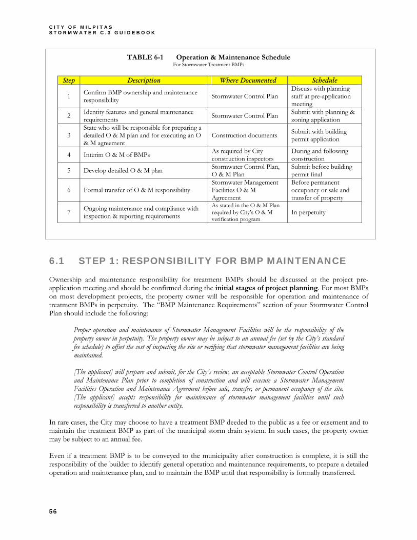
C I T Y O F M I L P I T A S S T O R M W A T E R C . 3 G U I D E B O O K
56
TABLE 6-1 Operation & Maintenance Schedule For Stormwater Treatment BMPs
6.1 STEP 1: RESPONSIBILITY FOR BMP MAINTENANCE
Ownership and maintenance responsibility for treatment BMPs should be discussed at the project pre-application meeting and should be confirmed during the initial stages of project planning. For most BMPs on most development projects, the property owner will be responsible for operation and maintenance of treatment BMPs in perpetuity. The “BMP Maintenance Requirements” section of your Stormwater Control Plan should include the following:
Proper operation and maintenance of Stormwater Management Facilities will be the responsibility of the property owner in perpetuity. The property owner may be subject to an annual fee (set by the City’s standard fee schedule) to offset the cost of inspecting the site or verifying that stormwater management facilities are being maintained.
[The applicant] will prepare and submit, for the City’s review, an acceptable Stormwater Control Operation and Maintenance Plan prior to completion of construction and will execute a Stormwater Management Facilities Operation and Maintenance Agreement before sale, transfer, or permanent occupancy of the site. [The applicant] accepts responsibility for maintenance of stormwater management facilities until such responsibility is transferred to another entity.
In rare cases, the City may choose to have a treatment BMP deeded to the public as a fee or easement and to maintain the treatment BMP as part of the municipal storm drain system. In such cases, the property owner may be subject to an annual fee.
Even if a treatment BMP is to be conveyed to the municipality after construction is complete, it is still the responsibility of the builder to identify general operation and maintenance requirements, to prepare a detailed operation and maintenance plan, and to maintain the BMP until that responsibility is formally transferred.
Step Description Where Documented Schedule
1 Confirm BMP ownership and maintenance responsibility Stormwater Control Plan
Discuss with planning staff at pre-application meeting
2 Identity features and general maintenance requirements Stormwater Control Plan Submit with planning &
zoning application
3 State who will be responsible for preparing a detailed O & M plan and for executing an O & M agreement
Construction documents Submit with building permit application
4 Interim O & M of BMPs As required by City construction inspectors
During and following construction
5 Develop detailed O & M plan Stormwater Control Plan, O & M Plan
Submit before building permit final
6 Formal transfer of O & M responsibility Stormwater Management Facilities O & M Agreement
Before permanent occupancy or sale and transfer of property
7 Ongoing maintenance and compliance with inspection & reporting requirements
As stated in the O & M Plan required by City’s O & M verification program
In perpetuity
C H A P T E R 6 B M P M A I N T E N A N C E
57
6.2 STEP 2: GENERAL MAINTENANCE REQUIREMENTS
Following are general maintenance requirements for some common treatment BMPs. You can use this information to prepare your Stormwater Control Plan. In addition, see the BMP O&M Fact Sheets in CASQA’s Stormwater Best Management Practice Handbook (Municipal) at www.cabmphandbooks.com and the additional BMP O&M Fact Sheets prepared by SCVURPPP at www.scvurppp.org.
► VEGETATED FILTERS, SWALES, AND BIORETENTION AREAS
These BMPs remove pollutants primarily by filtering runoff slowly through an active layer of soil. Routine maintenance is needed to insure that flow is unobstructed, that erosion is prevented, and that soils are held together by plant roots and are biologically active. Typical maintenance consists of the following:
♦ Inspect inlets for channels, exposure of soils, or other evidence of erosion. Clear any obstructions and remove any accumulation of sediment. Examine rock or other material used as a splash pad and replenish if necessary.
♦ Inspect outlets for erosion or plugging.
♦ Inspect side slopes for evidence of instability or erosion and correct as necessary.
♦ Observe soil at the bottom of the swale or filter for uniform percolation throughout. If portions of the swale or filter do not drain within 48 hours after the end of a storm, the soil should be tilled and replanted. Remove any debris or accumulations of sediment.
♦ Confirm that check dams and flow spreaders are in place and level and that channelization within the swale or filter is effectively prevented.
♦ Examine the vegetation to insure that it is healthy and dense enough to provide filtering and to protect soils from erosion. Replenish mulch as necessary, remove fallen leaves and debris, prune large shrubs or trees, and mow turf areas. Confirm that irrigation is adequate and not excessive. Replace dead plants and remove invasive vegetation.
♦ Abate any potential vectors by filling holes in the ground in and around the swale and by insuring that there are no areas where water stands longer than 48 hours following a storm. If mosquito larvae are present and persistent, contact the Santa Clara County Vector Control District for information and advice. Mosquito larvicides should be applied only when absolutely necessary and then only by a licensed individual or contractor.
► PLANTER BOXES
Planter boxes capture runoff from downspouts or sheet flow from plazas and paved areas. The runoff briefly floods the surface of the box and then percolates through an active soil layer to drain rock below. Typical maintenance consists of the following:
♦ Examine downspouts from rooftops or sheet flow from paving to insure that flow to the planter is unimpeded. Remove any debris and repair any damaged pipes. Check splash blocks or rocks and repair, replace, or replenish as necessary.
C I T Y O F M I L P I T A S S T O R M W A T E R C . 3 G U I D E B O O K
58
♦ Examine the overflow pipe to make sure that it can safely convey excess flows to a storm drain. Repair or replace any damaged or disconnected piping.
♦ Check the underdrain piping to make sure it is intact and unobstructed.
♦ Observe the structure of the box and fix any holes, cracks, rotting, or failure.
♦ Check that the soil is at the appropriate depth to allow a 12" reservoir above the soil surface and is sufficient to effectively filter stormwater. Remove any accumulations of sediment, litter, and debris. Confirm that soil is not clogging and that the planter will drain within 3-4 hours after a storm event.
♦ Determine whether the vegetation is dense and healthy. Replace dead plants. Prune or remove any overgrown plants or shrubs that may interfere with planter operation. Clean up fallen leaves or debris and replenish mulch. Remove any nuisance or invasive vegetation.
► SAND FILTERS
Sand filters remove pollutants by physical settling and adsorption as runoff flows through the granular media. Unlike the soil in planter boxes and vegetative filters, the sand does not support soil organisms that keep the medium mixed and adsorptive. Sand filters may be more prone to blinding (development of an impermeable surface layer) and clogging (accumulations of clayey sediments deeper in the filter).
Typical maintenance consists of the following:
♦ Check inlets. Remove any accumulated sediment or debris. Examine splash blocks or rock and replace or replenish as needed.
♦ Insure that the overflow pipe or spill point is clear and can convey excess flows to storm drains. Look for any evidence of channeling or erosion. Replace or replenish rocks or armoring.
♦ Observe the structure of the filter and fix any holes, cracks, or failure.
♦ Look at the sand to insure that the level allows a 12″ reservoir above the surface. Remove any debris or accumulated sediment. Confirm that the surface of the sand is not blinded by fine sediment. If it is, remove and replace the top layer of sand. Check that the filter as a whole is not clogged. If it is, all media may need to be removed and replaced. If no blinding or clogging is apparent, rake the surface of the sand.
♦ Check the underdrain piping to make sure it is intact and unobstructed.
► WET, EXTENDED WET DETENTION, AND DRY DETENTION PONDS
These larger-scale BMPs remove pollutants by detaining runoff in a quiescent pool long enough for some of the particulates to settle to the bottom. They require both routine (preventative) maintenance and non-routine maintenance.
Contact the Santa Clara County Vector Control District to coordinate design and maintenance requirements for any pond, basin, vault, or other device that is designed to hold, or does hold water longer than 72 hours.
Typical routine maintenance consists of the following:
C H A P T E R 6 B M P M A I N T E N A N C E
59
♦ Examine inlets to insure that piping is intact and not plugged. Remove accumulated sediment or debris near the inlet.
♦ Examine outlets and overflow structures and remove any debris or sediment that could plug the outlets. Identify and correct any sources of sediment and debris. Check rocks or other armoring and replace as necessary.
♦ Inspect embankments, dikes, berms, and side slopes for signs of erosion or structural deficiencies.
♦ Confirm that any fences around the facility are secure.
♦ Control vectors by filling any holes in or around the pond and examine the pond for evidence of mosquito larvae.
Typical non-routine maintenance includes the following:
♦ Dredge accumulated sediment. This may be required every five to 15 years, and more frequently if there are excess sources of sediment (as may occur on newly constructed sites where soils are not yet stabilized). Dredging is usually a major project requiring mechanized equipment. The work will include an initial survey of depths and elevations, sediment sampling and testing, removal, transport, and disposal of accumulated sediment, and reestablishment of original design grades and sections.
♦ Remove invasive plants. Depending on the success of the design and the rate of sedimentation, ponds may be subject to excessive growth of rooted macrophytes, which reduce the effective area of the pond and create quiescent surface water that supports mosquito larvae. Removal may require a level of effort similar to dredging.
6.3 STEP 3: IDENTIFY O&M PLAN PREPARER
Construction documents submitted for building permit approval must include a table summarizing the permanent structural BMPs incorporated in the Stormwater Control Plan. Accompany this table with a statement of:
♦ The name and contact information of the individual responsible for preparing the detailed operation and maintenance plan.
♦ The name and contact information of the individual responsible for executing a Stormwater Facilities Operation and Maintenance Agreement with the City.
6.4 STEP 4: INTERIM OPERATION & MAINTENANCE
In accordance with Provision C.3.e.ii. of the Stormwater NPDES permit, the project proponent must provide a signed statement “accepting responsibility for maintenance [of stormwater treatment BMPs] until the responsibility is transferred to another entity…”
As described in Step 1, state this in your Stormwater Control Plan.
C I T Y O F M I L P I T A S S T O R M W A T E R C . 3 G U I D E B O O K
60
During construction, ensure that BMPs are built correctly, and avoid construction-phase errors that can cause maintenance problems later. Some specific concerns are described below.
► CONSTRUCTION-PHASE CONCERNS FOR STORMWATER BMPS
Clogging with Construction-Phase Sediments. Infiltration BMPs (including dry wells and infiltration trenches) and sand filters are especially vulnerable to being clogged with fine sediment from construction-related erosion. Consider plugging inlets and/or using sandbags to prevent sediment-laden runoff from reaching the BMP. Also, consider bringing the BMP “on-line” only after the site is stabilized.
Compaction of Soils. Grading and movement of heavy equipment can compact soils that are intended to absorb runoff or provide infiltration to groundwater and can greatly increase runoff coefficients in what should be pervious areas of the site. Carefully stake and protect BMP areas and open-space areas and avoid unnecessary grading and compaction.
Differential Settlement. Provide adequate foundations for drainage structures and especially for concrete aprons at basin inlets and outlets. Differential settlement can create unintended shallow puddles or ponds, which can create mosquito problems.
Misaligned Grades or Inadequate Reveal. Many BMPs require subtle control of elevations and may be unfamiliar to grading and landscaping contractors. For example:
♦ Swales or landscape retention areas may be designed with inlet grates mounted a few or several inches above the surrounding turf so that runoff will pond to a specified depth before overflowing into the grate. The surrounding earth and topsoil must be carefully graded to achieve this effect.
♦ Swales or vegetated filter strips may be designed to accept sheet runoff from adjacent paved areas. Grading of the filter strip must provide adequate reveal for turf buildup, or runoff will pond on the edge of the paved surface.
The detailed O&M plan should incorporate solutions to any problems noted or changes that occurred during construction.
6.5 STEP 5: DETAILED OPERATION & MAINTENANCE PLAN
After the construction drawings and specifications for your stormwater treatment and hydrograph modification BMPs has been completed, prepare a detailed operation and maintenance (O&M) plan. The O&M plan may be simple or complex depending on the type of BMPs selected and implemented for your project. For example, scheduled maintenance for landscape detention areas may require little more explanation than irrigation cycles, plant care, and observation of any drainage problems. In contrast, a system with pumps and sumps should incorporate manufacturer’s maintenance recommendations, warranty information, detailed operating plans, and a seasonal schedule for inspections. Wet ponds or constructed wetlands will require detailed O&M plans to monitor and, if necessary, abate problems with mosquitoes or excessive macrophyte growth. In addition, it may be advisable to manage wet ponds or wetlands to avoid designation as critical habitat for endangered species.
Appendix H provides instructions for the preparation of O&M plans. Example Stormwater Control Operation and Maintenance Plans are in Appendix I.
C H A P T E R 6 B M P M A I N T E N A N C E
61
Submit your Stormwater Control Operation and Maintenance Plan before completion of construction and before applying for a Certificate of Occupancy.
6.6 STEP 6: TRANSFER RESPONSIBILITY
As part of the detailed O&M plan, note the expected date when responsibility for operation and maintenance will be transferred. When this transfer of responsibility takes place, notify the City and execute a Stormwater Management Facilities Operation and Maintenance Agreement. The agreement runs with the land; future owners will also be responsible for BMP operation and maintenance.
6.7 STEP 7: OPERATION & MAINTENANCE VERIFICATION
In accordance with NPDES permit Provision C.3.e, the City will implement a Stormwater Control Operation and Maintenance Verification Program, including periodic site inspections. The verification program is described in further detail in Appendix H.
References and Resources • RWQCB Order 01-119, Provision C.3.e • Start at the Source (BASMAA, 1999) pp. 139-145. • Urban Runoff Quality Management (WEF/ASCE, 1998). pp 186-189. • Stormwater Management Manual (Portland, 2002). Chapter 6.0. • California Storm Water Best Management Practice Handbooks Operation and Maintenance Fact Sheets (CASQA,
2003). TC-10 Infiltration Trench TC-11 Infiltration Basin TC-12 Retention/Irrigation TC-20 Wet Ponds TC-21 Constructed Wetlands TC-22 Extended Detention Basin TC-30 Vegetated Swale TC-31 Vegetated Buffer Strip TC-32 Bioretention TC-40 Media Filter TC-50 Water Quality Inlet TC-60 Multiple System Fact Sheet MP-20 Wetland MP-40 Media Filter MP-50 Wet Vault MP-51 Vortex Separator MP-52 Drain Inlet
• SCVURPPP Operation & Maintenance Fact Sheets: Exfiltration Trench Hydrodynamic Separators Planter Boxes Porous Pavement Roof Gardens Underground Detention Systems
• Best Management Practices Guide (Public Telecommunications Center for Hampton Roads, 2002)

C H A P T E R 7 W A I V E R A N D / O R A L T E R N A T I V E C O M P L I A N C E O P T I O N S
63
Chapter
7 7 WAIVER AND ALTERNATIVE
COMPLIANCE OPTIONS
Alternatives for meeting stormwater control requirements for your site by participating in a regional stormwater facility, by implementing compensatory mitigation, or obtaining an exemption.
he program approved by the RWQCB is shown in Appendix Q. Applications of BMPs to the extent practicable will still be required at sites where waivers are granted. Written applications for waiver or alternative compliance is required as part of the Stormwater Control Plan submittal.
Waiver – A waiver waives the requirement to install permanent onsite stormwater treatment measures. Even if the waiver is granted, the applicant will still be required to submit a Stormwater Control Plan delineating other C3 components (e.g., Source Control Measures, Site Design Measures, Pesticide Reduction Measures). To apply for a waiver, the applicant must submit the C.3 Waiver Form found in Appendix N.
Alternative Compliance - In lieu of installing permanent onsite stormwater treatment measures on a project an applicant can apply for Alternative Compliance by participating in a Regional Stormwater Treatment Facility, a Treatment Trade, or Stream Restoration. To apply for Alternative Compliance, the applicant must submit the C.3 Alternative Compliance Form found in Appendix N.
The RWQCB’s permit allows the City to establish a “waiver and compensatory mitigation” program for Smart Growth Projects. A Smart Growth Project falls within one or more of the following categories:
♦ Projects located within the City’s Mid-town Specific Plan area, which is the City’s urban core (See Appendix Q, Exhibit 1).
♦ Projects located within the City’s Transit Oriented Development Overlay Zoning District (See Appendix Q, Exhibit 1).
♦ Affordable and Senior Housing Development Projects that meet the criteria of Government Code 65589.5(h)(3)4, or 65915(b)4.
♦ Projects on real property, the expansion, redevelopment, or reuse of which may be complicated by the presence or potential presence of a hazardous substance, pollutant, or contaminants. These properties are commonly referred to as “brownfields.”
♦ Projects located within the Transit Sub-area designated by the City Council for either or both, redevelopment involving densities of 31 or more dwelling units per acre, or for commercial or industrial redevelopments that will increase the floor area ratio from less than 1 to more than 1 (See Appendix Q, Exhibits 2A and 2B).
4 Refer to Appendix N (C.3 Waiver Form on page N-8) for a definition of Government Code 65589.5(h)(3) and 65915(b).
T

C I T Y O F M I L P I T A S S T O R M W A T E R C . 3 G U I D E B O O K
64
Other C.3 requirements – including site designs to minimize imperviousness and structural source control BMPs – may still apply.
City staff can provide up-to-date information on the City’s proposed waiver and compensatory mitigation program and how it might apply to your project.
References and Resources • RWQCB Order 01-119, Provision C.3.g
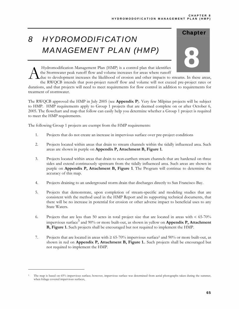
C H A P T E R 8 H Y D R O M O D O F I C A T I O N M A N A G E M E N T P L A N ( H M P )
65
Chapter
8 8 HYDROMODIFICATION
MANAGEMENT PLAN (HMP)
Hydromodification Management Plan (HMP) is a control plan that identifies the Stormwater peak runoff flow and volume increases for areas where runoff due to development increases the likelihood of erosion and other impacts to streams. In these areas, the RWQCB intends that post-project runoff flow and volume will not exceed pre-project rates or
durations, and that projects will need to meet requirements for flow control in addition to requirements for treatment of stormwater.
The RWQCB approved the HMP in July 2005 (see Appendix P). Very few Milpitas projects will be subject to HMP. HMP requirements apply to Group 1 projects that are deemed complete on or after October 6, 2005. The flowchart and map that follow can easily help you determine whether a Group 1 project is required to meet the HMP requirements.
The following Group 1 projects are exempt from the HMP requirements:
1. Projects that do not create an increase in impervious surface over pre-project conditions
2. Projects located within areas that drain to stream channels within the tidally influenced area. Such areas are shown in purple on Appendix P, Attachment B, Figure 1.
3. Projects located within areas that drain to non-earthen stream channels that are hardened on three sides and extend continuously upstream from the tidally influenced area. Such areas are shown in purple on Appendix P, Attachment B, Figure 1. The Program will continue to determine the accuracy of this map.
4. Projects draining to an underground storm drain that discharges directly to San Francisco Bay.
5. Projects that demonstrate, upon completion of stream-specific and modeling studies that are consistent with the method used in the HMP Report and its supporting technical documents, that there will be no increase in potential for erosion or other adverse impact to beneficial uses to any State Waters.
6. Projects that are less than 50 acres in total project size that are located in areas with < 65-70% impervious surface5 and 90% or more built-out, as shown in yellow on Appendix P, Attachment B, Figure 1. Such projects shall be encouraged but not required to implement the HMP.
7. Projects that are located in areas with ≥ 65-70% impervious surface5 and 90% or more built-out, as shown in red on Appendix P, Attachment B, Figure 1.. Such projects shall be encouraged but not required to implement the HMP.
5 The map is based on 65% impervious surface; however, impervious surface was determined from aerial photographs taken during the summer,
when foliage covered impervious surfaces.
A

C I T Y O F M I L P I T A S S T O R M W A T E R C . 3 G U I D E B O O K
66
For assistance in developing a HMP for your project, refer to the Santa Clara Valley Urban Runoff Pollution Prevention Program’s HMP Final Report, dated April 2005. You can locate this document via the SCVURPPP’s website at www.scvurppp.org.
At the time of printing, additional HMP guidelines were being developed. Contact City staff to obtain further information.
Even if your project does not need to meet the HMP requirements, project applicants are encouraged to use “dual-purpose” designs. These designs control pollutants and reduce runoff quantities by minimizing imperviousness and by slowing, retaining, and detaining runoff flows. The design approach recommended in Chapter 5 achieves “dual purpose” by distributing small detention areas throughout the site, increasing the time it takes for runoff to reach storm drains.
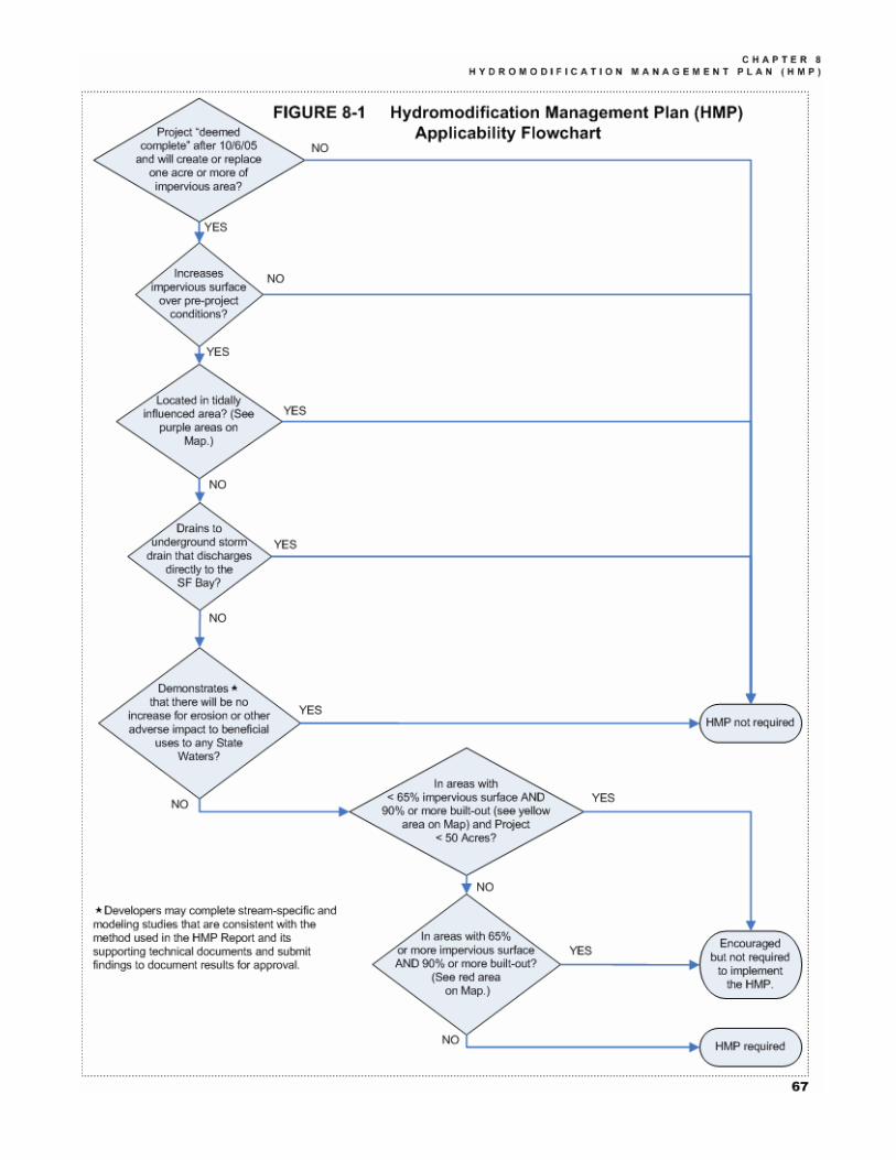

A B B R E V I A T I O N S
69
ABBREVIATIONS
BMP Best Management Practices
CEQA California Environmental Quality Act
COA Condition of Approval
HMP Hydromodification Management Plan
IPM Integrated Pest Management
LID Low Impact Development
NPDES National Pollutant Discharge Elimination System
O&M Operation and Maintenance
OPR Governor’s Office of Planning and Research
RWQCB Regional Water Quality Control Board
SCVURPPP Santa Clara Valley Urban Runoff Pollution Prevention Program
SWPPP Storm Water Pollution Prevention Plan
USEPA United States Environmental Protection Agency
WEF Water Environment Federation


B I B L I O G R A P H Y
71
BIBLIOGRAPHY
• ABAG. Association of Bay Area Governments. 1998. Manual of Standards for Erosion and Sediment Control Measures.
• ASCE. 1996. American Society of Civil Engineers. Hydrology Handbook, Second Edition. ASCE Manuals and Reports on Engineering Practice No. 28. ISBN 0-7844-0138-1. 784 pp.
• Barr Engineering. 2001. Minnesota Urban Small Sites BMP Manual. www.metrocouncil.org/environment/Watershed/bmp/manual.htm
• BASMAA. 1999. Bay Area Stormwater Management Agencies Association. Start at the Source: Design Guidance Manual for Stormwater Quality. Tom Richman and Associates. 154 pp. plus appendix. http://www.ci.milpitas.ca.gov/citydept/publicworks/urban_runoff.htm
• Bass, Ronald E., Albert I. Herson, and Kenneth M. Bogdan. CEQA Deskbook. 1999 (Second) Edition. Includes 2001 Supplement. Solano Press Books, Point Arena, CA. 414 pp. plus appendices.
• California. California Environmental Quality Act, Statutes and Guidelines. Access: http://ceres.ca.gov/ceqa/
• California Department of Transportation. 2001. Highway Design Manual. Access: http://www.dot.ca.gov/hq/oppd/hdm/hdmtoc.htm
• CASQA. 2003. California Stormwater Quality Association. California Stormwater BMP Handbooks. Four Handbooks: New Development and Redevelopment, Construction, Municipal, and Industrial/Commercial. Access: Download at www.cabmphandbooks.org
• Federal Interagency Stream Restoration Working Group. 1998. Stream Restoration: Principles, Processes, and Practices. Access: http://www.nrcs.usda.gov/technical/stream_restoration/
• Hampton Roads, VA. 2002. Best Management Practices Guide. Public Telecommunications Center. Access: www.hrstorm.org
• City of Milpitas. 2001. Coyote Creek Trail Public Draft Initial Study.
• City of Milpitas. 1994. General Plan. http://www.ci.milpitas.ca.gov/citydept/planning/generalplan.htm City of Milpitas Municipal Code. Title XI, Chapter 10: Zoning. Access: http://municipalcodes.lexisnexis.com/codes/milpitas/
• Natural Lands Trust. 2001. Growing Greener: Conservation by Design. Produced in cooperation with the Pennsylvania Department of Conservation and Natural Resources and the Governor’s Center for Local Government Services. September
2001. 20pp. http://www.natlands.org/pdffiles/growinggreener.pdf
• OPR. 1994. Governor’s Office of Planning and Research. Thresholds of Significance: Criteria for Defining Environmental Significance. CEQA Technical Advice Series. Sacramento, CA. Access via: http://ceres.ca.gov/planning/ceqa/thresholds.html
• OPR. 2000. Governor’s Office of Planning and Research. 2004 Planning, Zoning, and Development Laws. Sacramento, CA. Access at http://www.opr.ca.gov/planning/PlanningPubs.html#PZDL
• Portland. 2002. City of Portland Stormwater Management Manual. Access at: http://www.cleanrivers-pdx.org/tech_resources/2002_swmm.htm
• Maryland, 1999. Prince George’s County, Maryland. Low-Impact Development Design Strategies: An Integrated Design Approach. Department of Environmental Resources, Programs and Planning Division. June 1999. 150 pp. Access at www.lowimpactdevelopment.org
• Riley, Ann. 1998. Restoring Streams in Cities. Island Press, Washington, DC. 425 pp.
• RWQCB. 2001. California Regional Water Quality Control Board for the San Francisco Bay Region. Revised Order 01-024, NPDES Permit No. CAS029718, reissuing Waste Discharge Requirements for: Santa Clara Valley Water District, County of Santa Clara, City of Campbell, City of Cupertino, City of Los Altos, Town of Los Altos Hills, Town of Los Gatos, City of Milpitas, City of Monte Sereno, City of Mountain View, City of Palo Alto, City of San Jose, City of Santa Clara, City of Saratoga, and City of Sunnyvale, which have joined together to form the Santa Clara Valley Urban Runoff Pollution Prevention Program. 27 pp. Download Word file: http://www.swrcb.ca.gov/rwqcb2/OrderNum/01-024.doc
• RWQCB. 2001. California Regional Water Quality Control Board for the San Francisco Bay Region. Order No. 01-119, NPDES Permit No. CAS 029718. Amendment Revising Provision C.3. of Order No. 01-024. 21 pp. Download Word file: http://www.swrcb.ca.gov/rwqcb2/OrderNum/01-119final.doc
• RWQCB. 2002. California Regional Water Quality Control Board for the San Francisco Bay Region. Fact Sheet on New Development Provisions. 3 pp.
• Access: http://www.ci.milpitas.ca.gov/citydept/publicworks/stormwater_c3/permit_revisions.pdf
• Santa Clara County Department of Environmental Health. Pool Plan Check Guidelines and Spa Plan Check Guidelines. Access: http://www.sccgov.org.
• Schueler, Tom. 1995. Site Planning for Urban Stream Protection. Environmental Land Planning Series. Metropolitan Washington Council of Governments. 232 pp. Access from the Center for Watershed Protection at http://www.cwp.org/SPSP/TOC.htm
C I T Y O F M I L P I T A S S T O R M W A T E R C . 3 G U I D E B O O K
72
• SCBWMI. 2001. Santa Clara Basin Watershed Management Initiative. Watershed Characteristics Report. www.scbwmi.org.
• SCBWMI. 2003. Santa Clara Basin Watershed Management Initiative. Watershed Action Plan. www.scbwmi.org
• SCVURPPP. 1997. Santa Clara Valley Urban Runoff Pollution Prevention Program. Urban Runoff Management Plan. 74 pp. Access: http://www.ci.milpitas.ca.gov/citydept/publicworks/stormwater_c3/urmp_main.pdf
• SCVURPPP. 2002. Santa Clara Valley Urban Runoff Pollution Prevention Program. SCVURPPP Model List of Source Control Measures. Access: http://www.ci.milpitas.ca.gov/citydept/publicworks/stormwater_c3/mloscm.pdf
• SCVURPPP. 2002. Santa Clara Valley Urban Runoff Pollution Prevention Program. SCVURPPP Hydromodification Management Plan Report (Public Review Draft, June 2004). Access: www.scvurppp.org
• SCVURPPP. 2002. Santa Clara Valley Urban Runoff Pollution Prevention Program. Landscape Maintenance for Pest Reduction. Fact Sheet, 2 pp. Access: http://www.ci.milpitas.ca.gov/citydept/publicworks/stormwater_c3/guidebook_appendix/appendix_k.pdf
• SCVURPPP. 2004. Santa Clara Valley Urban Runoff Pollution Prevention Program. C.3 Stormwater Handbook. Guidance for Implementing Stormwater Requirements for New and Redevelopment Projects. Final Draft, May 2004. www.scvurppp.org
• United States Department of Agriculture. 1986. Technical Release 55 Documentation: Urban Hydrology for Small Watersheds. Natural Resources Conservation Service, Conservation Engineering Division. 164 pp. Access: ftp://ftp.wcc.nrcs.usda.gov/downloads/hydrology_hydraulics/tr55/tr55.pdf
• Washington. 2001. Washington State Department of Ecology. Stormwater Management Manual for Western Washington. Volumes I-V. Download at http://www.ecy.wa.gov/programs/wq/stormwater/manual.html
• WEF/ASCE. 1998. Water Environment Foundation/American Society of Civil Engineers. Urban Runoff Quality Management. WEF Manual of Practice No. 23, ASCE Manual and Report on Engineering Practice No. 87. ISBN 1-57278-039-8 ISBN 0-7844-0174-8. 259 pp. Access: Order from WEF or ASCE, www.wef.org or www.asce.org.
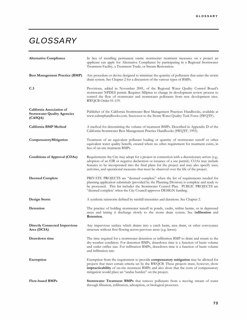
G L O S S A R Y
73
GLOSSARY
Alternative Compliance In lieu of installing permanent onsite stormwater treatment measures on a project an applicant can apply for Alternative Compliance by participating in a Regional Stormwater Treatment Facility, a Treatment Trade, or Stream Restoration.
Best Management Practice (BMP) Any procedure or device designed to minimize the quantity of pollutants that enter the storm drain system. See Chapter 2 for a discussion of the various types of BMPs.
C.3 Provisions, added in November 2001, of the Regional Water Quality Control Board’s stormwater NPDES permit. Requires Milpitas to change its development review process to control the flow of stormwater and stormwater pollutants from new development sites. RWQCB Order 01-119.
California Association of Stormwater Quality Agencies (CASQA)
Publisher of the California Stormwater Best Management Practices Handbooks, available at www.cabmphandbooks.com. Successor to the Storm Water Quality Task Force (SWQTF).
California BMP Method A method for determining the volume of treatment BMPs. Described in Appendix D of the California Stormwater Best Management Practice Handbooks (SWQTF, 1993).
CompensatoryMitigation Treatment of an equivalent pollutant loading or quantity of stormwater runoff or other equivalent water quality benefit, created where no other requirement for treatment exists, in lieu of on-site treatment BMPs.
Conditions of Approval (COAs) Requirements the City may adopt for a project in connection with a discretionary action (e.g., adoption of an EIR or negative declaration or issuance of a use permit). COAs may include features to be incorporated into the final plans for the project and may also specify uses, activities, and operational measures that must be observed over the life of the project.
Deemed Complete PRIVATE PROJECTS are “deemed complete” when the list of requirements needed for planning application submittals (provided by the Planning Division) is complete and ready to be processed. This list includes the Stormwater Control Plan. PUBLIC PROJECTS are “deemed complete’ when the City Council approves DESIGN funding.
Design Storm A synthetic rainstorm defined by rainfall intensities and durations. See Chapter 2.
Detention The practice of holding stormwater runoff in ponds, vaults, within berms, or in depressed areas and letting it discharge slowly to the storm drain system. See Infiltration and Retention.
Directly Connected Impervious Area (DCIA)
Any impervious surface which drains into a catch basin, area drain, or other conveyance structure without first flowing across pervious areas (e.g. lawns).
Drawdown time The time required for a stormwater detention or infiltration BMP to drain and return to the dry-weather condition. For detention BMPs, drawdown time is a function of basin volume and outlet orifice size. For infiltration BMPs, drawdown time is a function of basin volume and infiltration rate.
Exemption Exemption from the requirement to provide compensatory mitigation may be allowed for projects that meet certain criteria set by the RWQCB. These projects must, however, show impracticability of on-site treatment BMPs and also show that the costs of compensatory mitigation would place an “undue burden” on the project.
Flow-based BMPs Stormwater Treatment BMPs that remove pollutants from a moving stream of water through filtration, infiltration, adsorption, or biological processes.
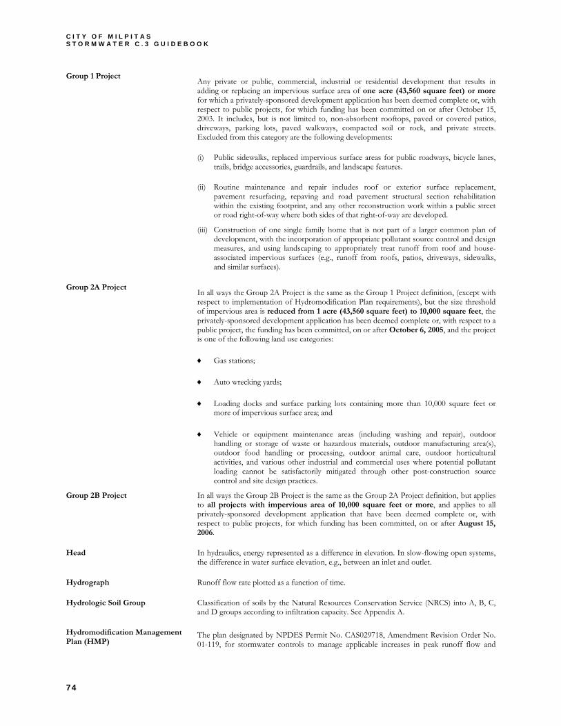
C I T Y O F M I L P I T A S S T O R M W A T E R C . 3 G U I D E B O O K
74
Group 1 Project Any private or public, commercial, industrial or residential development that results in adding or replacing an impervious surface area of one acre (43,560 square feet) or more for which a privately-sponsored development application has been deemed complete or, with respect to public projects, for which funding has been committed on or after October 15, 2003. It includes, but is not limited to, non-absorbent rooftops, paved or covered patios, driveways, parking lots, paved walkways, compacted soil or rock, and private streets. Excluded from this category are the following developments:
(i) Public sidewalks, replaced impervious surface areas for public roadways, bicycle lanes, trails, bridge accessories, guardrails, and landscape features.
(ii) Routine maintenance and repair includes roof or exterior surface replacement, pavement resurfacing, repaving and road pavement structural section rehabilitation within the existing footprint, and any other reconstruction work within a public street or road right-of-way where both sides of that right-of-way are developed.
(iii) Construction of one single family home that is not part of a larger common plan of development, with the incorporation of appropriate pollutant source control and design measures, and using landscaping to appropriately treat runoff from roof and house-associated impervious surfaces (e.g., runoff from roofs, patios, driveways, sidewalks, and similar surfaces).
Group 2A Project In all ways the Group 2A Project is the same as the Group 1 Project definition, (except with respect to implementation of Hydromodification Plan requirements), but the size threshold of impervious area is reduced from 1 acre (43,560 square feet) to 10,000 square feet, the privately-sponsored development application has been deemed complete or, with respect to a public project, the funding has been committed, on or after October 6, 2005, and the project is one of the following land use categories:
♦ Gas stations;
♦ Auto wrecking yards;
♦ Loading docks and surface parking lots containing more than 10,000 square feet or more of impervious surface area; and
♦ Vehicle or equipment maintenance areas (including washing and repair), outdoor handling or storage of waste or hazardous materials, outdoor manufacturing area(s), outdoor food handling or processing, outdoor animal care, outdoor horticultural activities, and various other industrial and commercial uses where potential pollutant loading cannot be satisfactorily mitigated through other post-construction source control and site design practices.
Group 2B Project In all ways the Group 2B Project is the same as the Group 2A Project definition, but applies to all projects with impervious area of 10,000 square feet or more, and applies to all privately-sponsored development application that have been deemed complete or, with respect to public projects, for which funding has been committed, on or after August 15, 2006.
Head In hydraulics, energy represented as a difference in elevation. In slow-flowing open systems, the difference in water surface elevation, e.g., between an inlet and outlet.
Hydrograph Runoff flow rate plotted as a function of time.
Hydrologic Soil Group Classification of soils by the Natural Resources Conservation Service (NRCS) into A, B, C, and D groups according to infiltration capacity. See Appendix A.
Hydromodification Management Plan (HMP)
The plan designated by NPDES Permit No. CAS029718, Amendment Revision Order No. 01-119, for stormwater controls to manage applicable increases in peak runoff flow and

G L O S S A R Y
75
increased runoff volume. HMP shall only apply to Group 1 Projects.
Impervious Surface Any material that prevents or substantially reduces infiltration of water into the soil. See Chapter 2.
Impracticable As applied to on-site treatment BMPs, technically infeasible or excessively costly, as demonstrated by set criteria.
Infeasible As applied to on-site treatment BMPs, impossible to implement because of technical constraints specific to the site.
Infiltration Seepage of runoff through the soil to mix with groundwater. See Retention and Detention.
Infiltration Device Any structure that is designed to infiltrate stormwater into the subsurface and, as designed, bypasses the natural groundwater protection afforded by surface or near surface soil.
Integrated Pest Management (IPM)
An approach to pest management that relies on information about the life cycles of pests and their interaction with the environment. Pest control methods are applied with the most economical means and with the least possible hazard to people, property, and the environment.
Intensity-duration-frequency (IDF)
An adjunct to the rational method (see), IDF allows calculation of the governing rainfall intensity based on the estimated time required for runoff flows from the farthest point of a drainage area to reach the point where peak flows are to be determined.
Lead Agency The public agency that has the principal responsibility for carrying out or approving a project (CEQA Guidelines §15367)
Low Impact Development Low Impact Development is an integrated site design methodology that uses small-scale detention and retention to replicate pre-existing site hydrological conditions.
Maximum Extent Practicable (MEP)
Standard, established by the 1987 amendments to the Clean Water Act, for the implementation of municipal stormwater pollution prevention programs. See Chapter 2.
National Pollutant Discharge Elimination System (NPDES)
As part of the 1972 Clean Water Act, Congress established the NPDES permitting system to regulate the discharge of pollutants from municipal sewers and industries. The NPDES was expanded in 1987 to incorporate permits for stormwater discharges as well.
Nomograph A chart that aids engineering calculations by representing the relationship among three variables. Nomographs in the California BMP Handbooks represent the relationship among percent annual capture, watershed imperviousness, and unit water quality volume.
Numeric Criteria Sizing requirements for stormwater treatment BMPs established in Provision C.3.d. of the RWQCB’s stormwater NPDES permit.
Permeable Pavements Pavements for roadways, sidewalks, or plazas that are designed to infiltrate runoff, including pervious concrete, pervious asphalt, unit-pavers-on-sand, and crushed gravel.
Percentile Rainfall Intensity A method of determining design rainfall intensity based on a ranking of storms, over a long period, by rainfall intensity and selection of a percentile.
Permanent Stormwater Pollution Prevention Measures
Any combination of source control measures, site design measures, and/or post-construction stormwater treatment measures that reduce stormwater pollution to the maximum extent practicable as required by NPDES Permit No. CAS029718 as amended by Order No. 01-119 issued by the California Regional Water Quality Control Board, San Francisco Bay Region.
Planned Unit Development (PUD)
Allows land to be developed in a manner that does not conform to existing zoning requirements. Allows greater flexibility and innovation because the PUD is regulated as one unit instead of each lot being regulated separately.
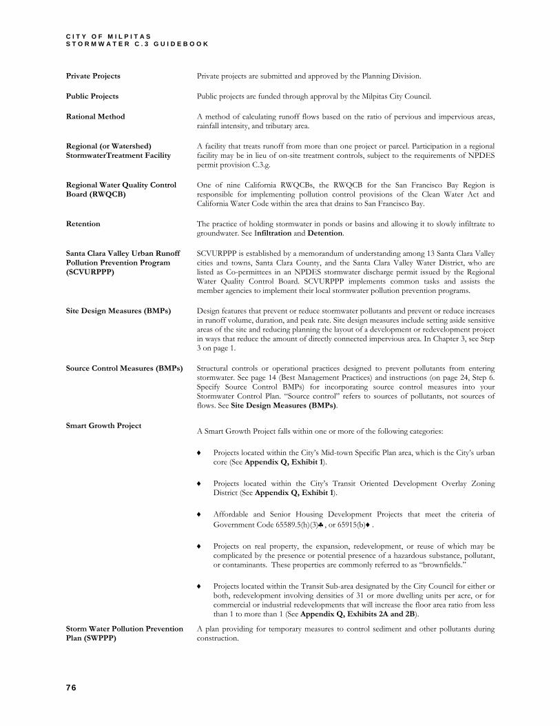
C I T Y O F M I L P I T A S S T O R M W A T E R C . 3 G U I D E B O O K
76
Private Projects Private projects are submitted and approved by the Planning Division.
Public Projects Public projects are funded through approval by the Milpitas City Council.
Rational Method A method of calculating runoff flows based on the ratio of pervious and impervious areas, rainfall intensity, and tributary area.
Regional (or Watershed) StormwaterTreatment Facility
A facility that treats runoff from more than one project or parcel. Participation in a regional facility may be in lieu of on-site treatment controls, subject to the requirements of NPDES permit provision C.3.g.
Regional Water Quality Control Board (RWQCB)
One of nine California RWQCBs, the RWQCB for the San Francisco Bay Region is responsible for implementing pollution control provisions of the Clean Water Act and California Water Code within the area that drains to San Francisco Bay.
Retention The practice of holding stormwater in ponds or basins and allowing it to slowly infiltrate to groundwater. See Infiltration and Detention.
Santa Clara Valley Urban Runoff Pollution Prevention Program (SCVURPPP)
SCVURPPP is established by a memorandum of understanding among 13 Santa Clara Valley cities and towns, Santa Clara County, and the Santa Clara Valley Water District, who are listed as Co-permittees in an NPDES stormwater discharge permit issued by the Regional Water Quality Control Board. SCVURPPP implements common tasks and assists the member agencies to implement their local stormwater pollution prevention programs.
Site Design Measures (BMPs) Design features that prevent or reduce stormwater pollutants and prevent or reduce increases in runoff volume, duration, and peak rate. Site design measures include setting aside sensitive areas of the site and reducing planning the layout of a development or redevelopment project in ways that reduce the amount of directly connected impervious area. In Chapter 3, see Step 3 on page 1.
Source Control Measures (BMPs) Structural controls or operational practices designed to prevent pollutants from entering stormwater. See page 14 (Best Management Practices) and instructions (on page 24, Step 6. Specify Source Control BMPs) for incorporating source control measures into your Stormwater Control Plan. “Source control” refers to sources of pollutants, not sources of flows. See Site Design Measures (BMPs).
Smart Growth Project A Smart Growth Project falls within one or more of the following categories:
♦ Projects located within the City’s Mid-town Specific Plan area, which is the City’s urban core (See Appendix Q, Exhibit 1).
♦ Projects located within the City’s Transit Oriented Development Overlay Zoning District (See Appendix Q, Exhibit 1).
♦ Affordable and Senior Housing Development Projects that meet the criteria of Government Code 65589.5(h)(3)♣, or 65915(b)♦.
♦ Projects on real property, the expansion, redevelopment, or reuse of which may be complicated by the presence or potential presence of a hazardous substance, pollutant, or contaminants. These properties are commonly referred to as “brownfields.”
♦ Projects located within the Transit Sub-area designated by the City Council for either or both, redevelopment involving densities of 31 or more dwelling units per acre, or for commercial or industrial redevelopments that will increase the floor area ratio from less than 1 to more than 1 (See Appendix Q, Exhibits 2A and 2B).
Storm Water Pollution Prevention Plan (SWPPP)
A plan providing for temporary measures to control sediment and other pollutants during construction.
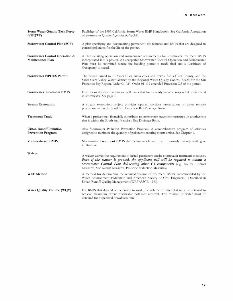
G L O S S A R Y
77
Storm Water Quality Task Force (SWQTF)
Publisher of the 1993 California Storm Water BMP Handbooks. See California Association of Stormwater Quality Agencies (CASQA).
Stormwater Control Plan (SCP) A plan specifying and documenting permanent site features and BMPs that are designed to control pollutants for the life of the project.
Stormwater Control Operation & Maintenance Plan
A plan detailing operation and maintenance requirements for stormwater treatment BMPs incorporated into a project. An acceptable Stormwater Control Operation and Maintenance Plan must be submitted before the building permit is made final and a Certificate of Occupancy is issued.
Stormwater NPDES Permit The permit issued to 13 Santa Clara Basin cities and towns, Santa Clara County, and the Santa Clara Valley Water District by the Regional Water Quality Control Board for the San Francisco Bay Region. Order 01-024. Order 01-119 amended Provision C.3 of the permit.
Stormwater Treatment BMPs Features or devices that remove pollutants that have already become suspended or dissolved in stormwater. See page 1.
Stream Restoration A stream restoration project provides riparian corridor preservation or water resoure protection within the South San Francisco Bay Drainage Basin.
Treatment Trade When a project may financially contribute to stormwater treatment measures on another site that is within the South San Francisco Bay Drainage Basin.
Urban Runoff Pollution Prevention Program
Also Stormwater Pollution Prevention Program. A comprehensive program of activities designed to minimize the quantity of pollutants entering storm drains. See Chapter 1.
Volume-based BMPs Stormwater Treatment BMPs that detain runoff and treat it primarily through settling or infiltration.
Waiver A waiver waives the requirement to install permanent onsite stormwater treatment measures. Even if the waiver is granted, the applicant will still be required to submit a Stormwater Control Plan delineating other C3 components (e.g., Source Control Measures, Site Design Measures, Pesticide Reduction Measures).
WEF Method A method for determining the required volume of treatment BMPs, recommended by the Water Environment Federation and American Society of Civil Engineers. Described in Urban Runoff Quality Management (WEF/ASCE, 1993).
Water Quality Volume (WQV) For BMPs that depend on detention to work, the volume of water that must be detained to achieve maximum extent practicable pollutant removal. This volume of water must be detained for a specified drawdown time