STORMWATER and EROSION CONTROL REGULATIONS CHRISTIAN COUNTY, MISSOURI · 2016-10-26 · Christian...
116
Christian County Stormwater and Erosion Control Regulations Article 1 – General Provisions 1 STORMWATER and EROSION CONTROL REGULATIONS CHRISTIAN COUNTY, MISSOURI ARTICLE 1. GENERAL PROVISIONS Section 1. Scope These design criteria set forth the minimum standards for design of storm drainage facilities on public right-of-way and private property in the unincorporated areas of Christian County, Missouri. Section 2. Authority These design criteria and standards set forth herein have been adopted by the Christian County Commission, in accordance with the procedures and authority set forth in the Christian County Zoning Regulations and the Christian County Subdivision Regulations. Any development or grading begun after the date of passage of these criteria and standards which does not comply with the requirements set forth herein shall be deemed to be in violation of the requirements established herein; and shall be subject to the following enforcement measures and penalties: A. Any person or entity violating any of the provisions of these Stormwater and Erosion Control Regulations, or any amendment or supplement thereto, shall be deemed guilty of a misdemeanor and, upon conviction thereof, shall be fined not more than one thousand dollars ($1000.00). B. Each and every day during which such illegal location, erection and/or construction may be deemed a separate offense. Section 3. Interpretations Where any of the provisions contained herein may be unclear or ambiguous as they pertain to a particular site or situation, interpretations of the policies, criteria, and standards set forth herein shall be made in writing by the Christian County Engineer. Such written interpretations shall be kept on file for future reference for use in similar situations, and shall be incorporated in subsequent revisions for the standards, if deemed necessary for general reference. Section 4. Appeals Where disagreements may arise over the interpretation of the requirements set forth herein, appeals may be made in accordance with procedures established by the Christian County Zoning Regulations, the Christian County Subdivision Regulations, or the Christian Building Regulations, as applicable.
Transcript of STORMWATER and EROSION CONTROL REGULATIONS CHRISTIAN COUNTY, MISSOURI · 2016-10-26 · Christian...

Christian County Stormwater and Erosion Control Regulations
Article 1 – General Provisions
1
STORMWATER and EROSION CONTROL
REGULATIONS CHRISTIAN COUNTY, MISSOURI
ARTICLE 1. GENERAL PROVISIONS
Section 1. Scope These design criteria set forth the minimum standards for design of storm drainage
facilities on public right-of-way and private property in the unincorporated areas of
Christian County, Missouri.
Section 2. Authority
These design criteria and standards set forth herein have been adopted by the Christian
County Commission, in accordance with the procedures and authority set forth in the
Christian County Zoning Regulations and the Christian County Subdivision Regulations.
Any development or grading begun after the date of passage of these criteria and
standards which does not comply with the requirements set forth herein shall be deemed
to be in violation of the requirements established herein; and shall be subject to the
following enforcement measures and penalties:
A. Any person or entity violating any of the provisions of these Stormwater
and Erosion Control Regulations, or any amendment or supplement
thereto, shall be deemed guilty of a misdemeanor and, upon conviction
thereof, shall be fined not more than one thousand dollars ($1000.00).
B. Each and every day during which such illegal location, erection and/or
construction may be deemed a separate offense.
Section 3. Interpretations
Where any of the provisions contained herein may be unclear or ambiguous as they
pertain to a particular site or situation, interpretations of the policies, criteria, and
standards set forth herein shall be made in writing by the Christian County Engineer.
Such written interpretations shall be kept on file for future reference for use in similar
situations, and shall be incorporated in subsequent revisions for the standards, if deemed
necessary for general reference.
Section 4. Appeals
Where disagreements may arise over the interpretation of the requirements set forth
herein, appeals may be made in accordance with procedures established by the Christian
County Zoning Regulations, the Christian County Subdivision Regulations, or the
Christian Building Regulations, as applicable.

Christian County Stormwater and Erosion Control Regulations
Article 1 – General Provisions
2
Section 5. Stormwater Management Plan Requirements A. General Requirements
1. The owner or operator of land development activities not exempted under Section 6 of this Article must submit a stormwater management plan. 2. The stormwater management plan shall include the specific required elements that are listed and/or described in the Christian County Stormwater and Erosion Control Regulations, as amended or provide sufficient analysis as detailed in Article 8 which demonstrates that the proposed development will not increase runoff levels beyond those deemed acceptable based on these regulations. Additional information shall be provided as necessary to allow an adequate review of the site conditions. 3. No approval for a building permit shall be issued until the required stormwater management plan is approved by the Planning Administrator in coordination with the County Engineer. 4. The developer/applicant is responsible for the review expenses of the County Engineer.
Section 6. Developments Exempt from a Stormwater Management Plan It is acknowledged that any exemptions are reviewed by the Planning Administrator and should not be construed as an opportunity to circumvent the letter and spirit of the Christian County Stormwater and Erosion Control Regulations. It is also not the intent of Christian County Government to place undue and unreasonable hardships on individual business and property owners. A development shall be required to submit a Stormwater Management Plan unless it meets the criteria put forth in this Section. A. Responsibilities of Exempt Developments
The exemptions listed in sub-section B shall not be construed as exempting these developments and redevelopments from onsite drainage improvements that may be required in accordance with building and construction codes, nor from compliance with any sections of Article 2, the County’s Illicit Discharge ordinance, nor from providing adequate erosion prevention and sediment control measures to protect adjoining property owners and the public right-of-way.

Christian County Stormwater and Erosion Control Regulations
Article 1 – General Provisions
3
B. Exemptions
The following developments and redevelopments are exempt from the requirements for a Soil and Erosion Control permit and for a Stormwater Management Plan: 1. Single to two-family individual residential dwellings in any given area that conform to all of the following criteria: (a) do not alter a drainage channel; and, (b) disturb less than one (1) acre of land; and, (c) are not part of a larger common plan of development or sale that would disturb one (1) acre or more; (d) do not alter the natural ground elevation by more than five (5) feet; (e) is not located within a mapped sinkhole, or if located outside of the allowable building areas and not located within 30 feet of spring, sinkhole, wetland, or watercourse. 2. Commercial or industrial development that conform to all of the following criteria: (a) disturbs less than one (1) acre of land; and, (b) is not part of a larger common plan of development or sale that would disturb one (1) acre or more; or, (c) adds less than five-thousand (5,000) square feet of impervious surface; and, (d) does not alter the drainage channel; and, (e) does not alter the natural ground elevation by more than five (5) feet; (f) is not located within a mapped sinkhole, or if located outside of the allowable building areas and not located within 30 feet of spring, sinkhole, wetland, or watercourse. 3. Minor land disturbing activities such as home gardens and individual home repairs, landscaping, or maintenance work; 4. Individual utility service connections, unless such activity is carried-out in conjunction with the clearing, grading, excavating, transporting, or filling of a lot or lots for which a grading permit would otherwise be required by the regulation; 5. Installation, maintenance or repair of individual septic tank lines or drainage fields, unless such activity is carried out in conjunction with the clearing, grading, excavating, transporting, or filling of a lot or lots for which a grading permit would otherwise be required by the regulation; 6. Installation of posts or poles; 7. Farming activities; 8. Emergency work to protect life or property, and emergency repairs, provided that the land area disturbed shall be shaped and stabilized in accordance with the requirements of this regulation as soon as practicable.
Christian County Stormwater and Erosion Control Regulations
Article 2 – Approvals and Permits Required
4
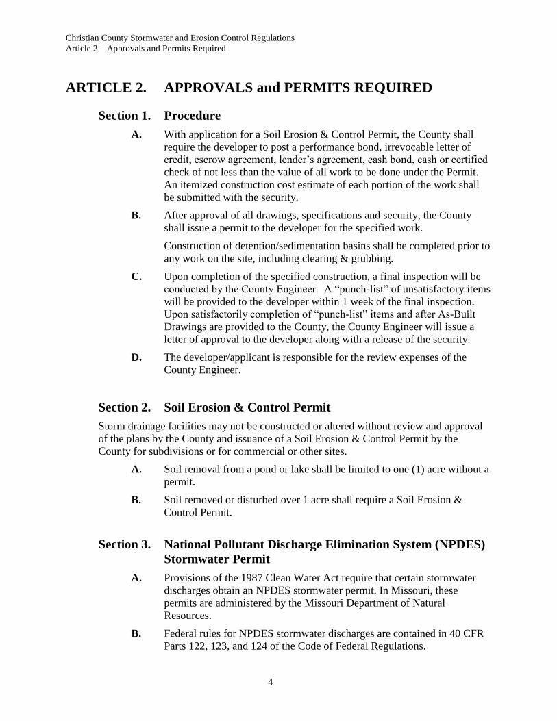
ARTICLE 2. APPROVALS and PERMITS REQUIRED
Section 1. Procedure
A. With application for a Soil Erosion & Control Permit, the County shall
require the developer to post a performance bond, irrevocable letter of
credit, escrow agreement, lender’s agreement, cash bond, cash or certified
check of not less than the value of all work to be done under the Permit.
An itemized construction cost estimate of each portion of the work shall
be submitted with the security.
B. After approval of all drawings, specifications and security, the County
shall issue a permit to the developer for the specified work.
Construction of detention/sedimentation basins shall be completed prior to
any work on the site, including clearing & grubbing.
C. Upon completion of the specified construction, a final inspection will be
conducted by the County Engineer. A “punch-list” of unsatisfactory items
will be provided to the developer within 1 week of the final inspection.
Upon satisfactorily completion of “punch-list” items and after As-Built
Drawings are provided to the County, the County Engineer will issue a
letter of approval to the developer along with a release of the security.
D. The developer/applicant is responsible for the review expenses of the
County Engineer.
Section 2. Soil Erosion & Control Permit
Storm drainage facilities may not be constructed or altered without review and approval
of the plans by the County and issuance of a Soil Erosion & Control Permit by the
County for subdivisions or for commercial or other sites.
A. Soil removal from a pond or lake shall be limited to one (1) acre without a
permit.
B. Soil removed or disturbed over 1 acre shall require a Soil Erosion &
Control Permit.
Section 3. National Pollutant Discharge Elimination System (NPDES)
Stormwater Permit
A. Provisions of the 1987 Clean Water Act require that certain stormwater
discharges obtain an NPDES stormwater permit. In Missouri, these
permits are administered by the Missouri Department of Natural
Resources.
B. Federal rules for NPDES stormwater discharges are contained in 40 CFR
Parts 122, 123, and 124 of the Code of Federal Regulations.

Christian County Stormwater and Erosion Control Regulations
Article 2 – Approvals and Permits Required
5
C. State NPDES stormwater regulations are contained in 10 CSR 20-6.200 of
the Code of State Regulations.
D. Per the State and Federal regulations cited above, a Storm Water Pollution
Prevention Plan (SWPPP) must be prepared for all developments
disturbing 1 acre or more. A copy of this plan shall be submitted to
Christian County with the application for a Soil Erosion & Control Permit.
The EPA resource “Developing Your Stormwater Pollution Prevention
Plan” should be used as a guide in preparing the SWPPP.
E. Additional provisions for NPDES stormwater permits for land disturbance
activities and information regarding a Christian County Soil Erosion &
Control Permit for land disturbance activities are contained in Article 3 of
these Criteria.
Section 4. "404" Permit
A. For certain activities which involve the discharge of dredged or fill
materials into the waters of the United States a Department of the Army
permit may be required as set forth in Section 404 of the Clean Water Act.
Rules for 404 permits are contained in 33 CFR Parts 320 through 330 of
the Code of Federal Regulations.
B. Determination of applicability for Section 404 requirements are generally
made by the Kansas City or Little Rock District office of the Corps of
Engineers.
C. A brochure regarding the Corps of Engineers regulatory program may be
obtained from the Corps offices.
Section 5. Coordination With Other Jurisdictions
A. Where proposed storm drainage facilities are located on property
adjoining to other local government jurisdictions design of storm drainage
facilities shall include provisions to receive or discharge storm water in
accordance with the requirements of the adjoining jurisdiction, in addition
to meeting County requirements
B. In these cases 2 additional sets of plans shall be submitted and will be
forwarded to the adjoining jurisdiction for review and comment.
C. No grading or construction of storm drainage facilities may commence
without prior notification of the Missouri One Call utility warning system
at 1-800-DIG-RITE, as required by law.
Christian County Stormwater and Erosion Control Regulations
Article 3 – Grading, Sediment and Erosion Control
6
ARTICLE 3. GRADING, SEDIMENT & EROSION CONTROL
Section 1. Goals & Objectives
The goal of this article is to effectively minimize erosion and discharge of sediment by
application of relatively simple and cost effective Best Management Practices.
A. This goal can be attained by meeting the following objectives:
1. Minimize the area disturbed by construction at any given time.
2. Stabilize disturbed areas as soon as possible by re-establishing sod,
other forms of landscaping, and completing proposed structures,
pavements and storm drainage systems.
3. Provide for containment of sediment until areas are stabilized.
4. Provide permanent erosion controls.
Section 2. General Design Guidelines
The following items must be considered in preparing a sediment and erosion control plan:
A. Temporary vs. Permanent Controls
The greatest potential for soil erosion occurs during construction.
Temporary controls are those that are provided for the purpose of
controlling erosion and containing sediment until construction is complete.
Temporary controls include straw or hay bale dikes, silt fences, erosion
control blankets etc., which are not needed after the area is stabilized.
Permanent controls consist of riprap, concrete trickle channels,
sedimentation/detention basins, etc., which will remain in place through
the life of the development.
It is possible for the same facility to serve both a temporary and permanent
purpose. The difference between temporary and permanent erosion control
should be clearly recognized in preparing a sediment and erosion control
plan.
B. Sheet Flow vs. Concentrated Flow
In areas where runoff occurs primarily as sheet flow, containment of
sediment is relatively simple. In these areas straw or hay bales, silt fences
and vegetative filter areas can be very effective.
Where concentrations of flow occur containment of sediment becomes
more difficult as the rate and volume of flow increase. In these areas more
sophisticated controls such as sedimentation basins must be provided.
C. Slope

Christian County Stormwater and Erosion Control Regulations
Article 3 – Grading, Sediment and Erosion Control
7
Control of erosion becomes progressively more difficult as the slope of
the ground increases. Areas with steeply sloping topography, and cut and
fill slopes must be given special consideration.
D. Soils and Geologic Setting
Area soils and the geologic setting must be considered in preparing the
plan and any special considerations deemed necessary for a particular site
provided.
E. Environmentally Sensitive Areas
Where construction occurs within the vicinity of permanent streams,
springs, sinkholes, lakes or wetlands, special attention must be given to
preventing discharge of sediment.
Section 3. Soil Erosion & Control Permits
A. Permit Exceptions
Soil Erosion & Control permits are required for all construction sites with
the following exceptions:
1. Grading for single family or duplex residences constructed in
subdivisions where approved sediment and erosion controls have
been constructed.
2. Emergency construction required repairing or replacing roads,
utilities, or other items affecting the general safety and well being
of the public.
For emergency construction sites which would otherwise be
required to obtain a permit, and for which remedial construction
will take more than 14 calendar days, application for the permit
must be made within 3 calendar days from the start of construction.
3. The following activities, provided that they are not located within
30 feet of a spring, sinkhole, wetland, or watercourse:
a. Gardening or landscaping normally associated with single-
family residences that cover less than 1/2 acres.
b. Grading and repair of existing roads or driveways.
c. Cleaning and routine maintenance of roadside ditches or
utilities.
d. Utility construction where the actual trench width is 2 feet
or less.
B. Permit Procedure
An approved grading, sediment and erosion control plan must be received
prior to issuance of a Soil Erosion & Control Permit:
The submittal and approval procedure is as follows for Subdivisions,
Commercial and Other Sites.

Christian County Stormwater and Erosion Control Regulations
Article 3 – Grading, Sediment and Erosion Control
8
The sediment and erosion control plan shall be submitted for review along
with the plans for the proposed improvements.
Permits for commercial, multi-family or major subdivisions will be issued
by the County after the project plans have been approved.
Section 4. Erosion & Sediment Control Plan
A. Professional Qualifications
Sediment and Erosion Control Plans must be prepared by and bear the seal
of an engineer, land surveyor, architect, landscape architect or geologist
registered to practice in the State of Missouri or by a Certified
Professional in Erosion and Sediment Control (CPESC) who has attained
certification by the Soil & Water Conservation Society
B. Plan Requirements
The sediment & erosion control plan must be drawn to scale and must
include the following items:
1. Location map at a scale of 1” = 2000’.
2. Legal description of the property.
3. North arrow and scale.
4. One-Call utility notification symbol.
5. Title block.
6. Signature block for licensed professional.
7. Design professional’s seal.
8. Existing topographic contours at five feet (5’) maximum intervals.
NOTE: Contours can not be interpolated from U.S.G.S. maps.
Each fifth (5th
) contour (index contour) shall be labeled and shown
in heavier line weight. Index contours must be labeled in a
sufficient number of locations to allow the pan to be followed.
Labels for existing and finish grade contour shall be distinguished
by use of different symbols or fonts.
9. Proposed grades.
10. Existing and proposed utilities.
11. Existing ground covering (open areas, tree masses, etc.)
12. Existing buildings, drives and pavements.
13. Proposed buildings or other structures, drives and pavements.
Christian County Stormwater and Erosion Control Regulations
Article 3 – Grading, Sediment and Erosion Control
9
14. Limits of area to be disturbed (shading preferred).
15. Location of erosion and sediment controls.
16. Details of non-standard erosion and sediment controls.
17. Seeding & mulching requirements.
18. Total site area, total disturbed area.
19. Location of stockpile areas, staging area, etc.
20. Location of temporary construction entrance.
C. Plan Exceptions
Plans will not be required in the following cases:
1. Grading associated solely with a single-family residence
2. Grading or filling of less than 1 acre if located outside of the
allowable building areas and not located within 30 feet of spring,
sinkhole, wetland, or watercourse.
These instances a grading permit can be issued, providing an inspection of
the site by a representative of the County does not reveal conditions that
would warrant preparation of a detailed plan.
D. Other Permits
1. NPDES Stormwater Permit
Construction sites where the area to be disturbed is 1 acre or more
must apply for a stormwater discharge permit from the Missouri
Department of Natural Resources.
Permit requirements are set forth in 10 CSR 20-6.200 of the
Missouri Clean Water Laws.
A Stormwater Pollution Prevention Plan (SWPPP) must be
prepared in accordance with Missouri Clean Water Laws. A copy
of the SWPPP must be submitted with the application for a Soil
Erosion & Control Permit.
2. "404" Permit
Grading activities in streams or wetlands may require a
Department of the Army Permit under Section 404 of the Clean
Water Act.
Christian County Stormwater and Erosion Control Regulations
Article 3 – Grading, Sediment and Erosion Control
10
Section 5. Design Standards & Criteria
A. Grading
1. Maximum Grades
Cut or fill slopes shall not exceed 4:1.
2. Maximum Height
Cut or fill slopes shall not exceed 15 feet in vertical height unless a
horizontal bench area at least 5 feet in width is provided for each
15 feet in vertical height.
3. Minimum Slope
Slope in grassed areas shall not be less than 1%.
4. Construction Specifications
Construction for streets must comply with specifications set forth
in the Christian County Road and Access Standards.
For all other areas, construction specifications stating requirements
for stripping, materials, subgrade compaction, placement of fills,
moisture and density control, preparation and maintenance of
subgrade must be included or referenced on the plans, or
accompanying specifications submitted.
5. Spoil areas
Broken concrete, asphalt and other spoil materials may not
be buried in fills within proposed building or pavement
areas.
Outside of proposed building and pavement areas, broken
concrete or stone may be buried in fills, provided it is
covered by a minimum of 2 feet of earth.
Burying of other materials in fills is prohibited.
6. Stockpile Areas
Location of proposed stockpile areas shall be outlined on
the plans, and specifications for proper drainage included.
7. Borrow Areas
The proposed limits of temporary borrow areas shall be outlined in
the plans and a proposed operating plan described on the grading
plan.
Temporary slopes in borrow areas may exceed the maximums set
forth above. At the time that borrow operations are completed, the
area shall be graded in accordance with the criteria set forth above,
and reseeded.
Christian County Stormwater and Erosion Control Regulations
Article 3 – Grading, Sediment and Erosion Control
11
B. Sediment Containment
1. Existing Vegetative Filter Area
Existing vegetative filter areas may be used where:
a. unconcentrated sheet flow occurs,
b. an area of existing vegetation a minimum of 30 feet in
width can be maintained between the area to be graded and
a property line, watercourse, sinkhole, spring, wetland or
classified lake,
c. existing ground slope is no greater than 5:1 (20%),
d. the existing vegetative growth is of sufficient density and in
sufficiently good condition to provide for filtration of
sediment.
Vegetative filter areas are a temporary and
permanent practice.
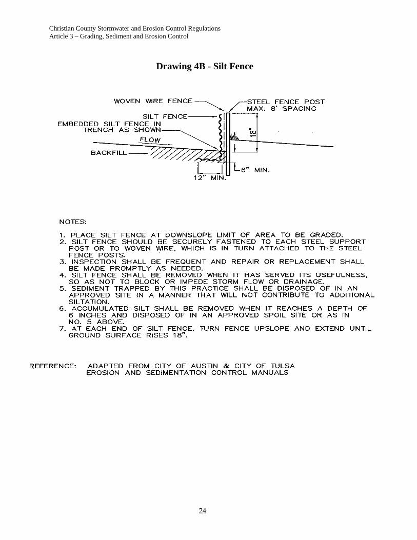
2. Hay/Straw Bale Dike, or Silt Fence
Containment areas constructed of hay or straw bales, or silt
fence may be provided in areas where:
a. unconcentrated sheet flow occurs,
b. an area of existing vegetation a minimum of 25 feet
in width cannot be maintained between the area to
be graded and a property line, watercourse,
sinkhole, spring, wetland or classified lake,
c. existing ground slope is no greater than 5:1 (20%),
d. concentrated flow from an area no greater than 1 acre
occurs and a minimum volume of 1000 cubic feet per acre
is contained behind the dike. Either cereal grain straw or
hay may be used for bale dikes. Straw/hay bale dikes shall
be constructed as shown in Drawing 4.
Straw/hale bale dikes and silt fences are temporary
practices.
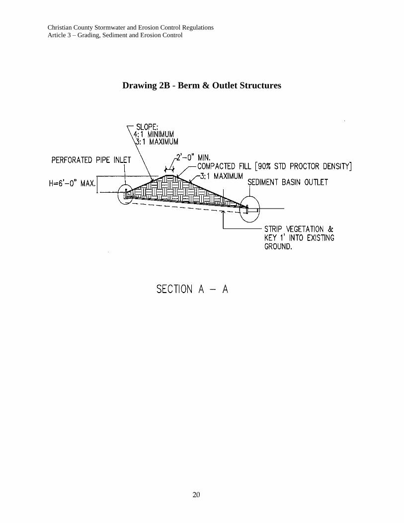
3. Temporary Containment Berms
Temporary containment berms may be provided for areas where
concentrated flow from areas greater than 1 acre and less than 5
acres occurs. Temporary containment berms must contain a
volume of 1000 cubic feet per acre of drainage area.
Temporary containment berms shall have a riprap outlet with a
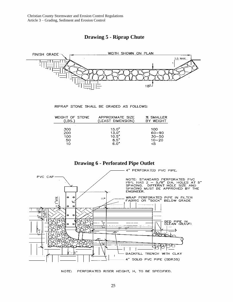
sediment filter as shown in Drawing 3, or a perforated pipe outlet
as shown in Drawing 6.
Details for temporary containment berms are shown in Drawing 2.

Christian County Stormwater and Erosion Control Regulations
Article 3 – Grading, Sediment and Erosion Control
12
Temporary containment berms and accumulated sediment
may be completely removed after the tributary area is
stabilized, and must be removed prior to final acceptance
and release of escrow.
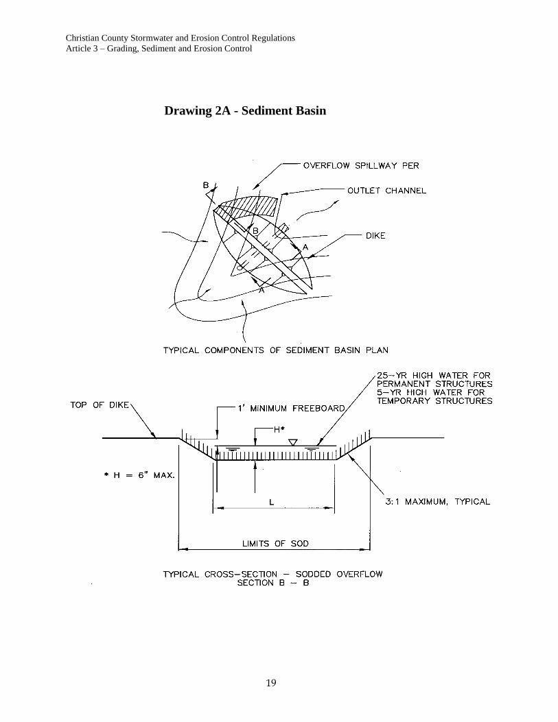
4. Permanent Sedimentation/Water Quality Basin
Permanent sediment/water quality basins shall be provided for all
areas where concentrated flow occurs from an area of 5 or more
acres or where 2 or more acres are stripped of vegetation.
Sediment basins shall be designed to detain 125% of the runoff
from 1" of rainfall from the development, for a period of between
24 and 48 hours. Runoff shall be calculated using the methods
contained in Chapter 2 of TR-55 (Reference 11), using the
recommended curve number for newly graded areas from Table 2-
2a.
a. Sediment basins shall be provided with an outflow structure
consisting of:
1. a flow restriction device which provides for the
required detention time,
2. an outfall pipe sized to carry the maximum
estimated outflow rate,
3. protective structures at the pipe outlet to prevent
crushing or damage of the end of the pipe,
4. protective structures to prevent blockage of
the pipe with debris,
5. erosion protection at the pipe outlet.
6. a typical outlet structure is shown in Drawing 2.
7. An overflow spillway capable of discharging the
peak flow rate for the 4% annual probability (25-
year) storm while maintaining a minimum freeboard
of 1 foot.
Overflow spillways may be sodded where the depth
of flow at the crest is limited to no greater than 6"
and outlet channel velocities do not exceed 5 feet
per second for the minor (25-year) storm.
Overflow spillways not meeting these restrictions
must be constructed of riprap, concrete or other
approved, non-erodible material.

Christian County Stormwater and Erosion Control Regulations
Article 3 – Grading, Sediment and Erosion Control
13
C. Erosion Protection
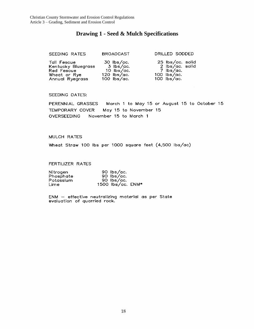
1. Seeding and Mulching
a. Permanent Seeding
Permanent seeding fertilizer and mulch shall be applied at
the rates set forth in Drawing 1 or according to other
specifications, which are approved with the Grading
Permit.
Permanent seeding seasons are from March 1 to May 15,
and August 15 to October 15.
b. Mulching
Where slopes are less than 4:1, cereal grain mulch is
required at the rate of 100 pounds per 1000 square feet
(4500 pounds per acre). Cereal grain mulch shall meet the
requirements of Section 802 of the State Specifications
(Reference 17) for Type 1 mulch.
Where slopes are 4:1 or greater Type 3 mulch
("hydromulch") meeting the requirements of Section 802 of
the State Specifications (Reference 17) shall be used.
c. Temporary Seeding
Whenever grading operations are suspended for
more than 30 calendar days between permanent
grass or seeding periods, all disturbed areas must be
reseeded with temporary cover according to
Drawing 1.
Temporary seeding season runs from May 15 to
November 15.
d. Overseeding
During the winter season (November 15 to March 1)
temporary seed and mulch shall be placed on all completed
areas or areas where grading is suspended for more than 30
calendar days. During this period seed, mulch, and soil
amendments shall be applied at the following rates:
Lime: 100% of specified quantity.*
Fertilizer: 75% of specified quantity.
Seed: 50% of specified quantity.
Mulch: 100% of specified quantity.
* Per Drawing 1.
Areas seeded during this period shall be reseeded and
mulched during the next permanent seeding season
according to seeding requirements.
Christian County Stormwater and Erosion Control Regulations
Article 3 – Grading, Sediment and Erosion Control
14
e. Maintenance
Seeded areas must be maintained for one year
following permanent seeding.
2. Cut and Fill Slopes
Cut and fill slopes shall be protected from erosion by
construction of straw bale dikes, silt fences, diversion berms, or
swales along the top of the slope.
Where drainage must be carried down the slopes, pipe
drains, concrete flumes, riprap chutes, or other impervious
areas must be provided. Suitable erosion control measures
such as riprap stilling basins, must be provided at the
bottom of the slope.
Diversions shall be maintained until permanent growth is
firmly established on the slopes.
Typical diversion details are shown in Drawing 3.
Riprap chute details are shown in Drawing 5.
3. Channels and Swales
Permanent channels and swales shall be provided with a
stabilized invert consisting of one of the following materials:
a. Sod
Where the average velocity of flow is 5 feet per second
or less and there is no base flow, the channel shall be
lined with sod.
For channels with a bottom width less than 15 feet, sod
shall extend up the side slope to a minimum height of
6" above the toe. (Drawing 7).
Channels with a bottom width of 15 feet or greater,
shall be graded as shown in Drawing 7 and contain
a low flow area, 15 feet in width lined with sod.
The remainder of the channel slopes shall be seeded
and mulched as provided above.
4. Erosion Control Blanket
Commercial erosion control blankets may be used in lieu of
sod provided that samples are submitted and approved by
the County. The guaranteed maintenance period shall be
one year.
Christian County Stormwater and Erosion Control Regulations
Article 3 – Grading, Sediment and Erosion Control
15
5. Non-Erosive Lining
In grass channels where base flow occurs, a non-erosive
low-flow channel of riprap or concrete must be provided.
Low flow channels shall have a minimum capacity of 5
cubic feet per second. Other suitable non-erosive materials
may be specified with approval of the County.
For channels which have an average velocity of 5 feet per
second or greater a non-erosive lining of riprap concrete or
other approved material must be provided.
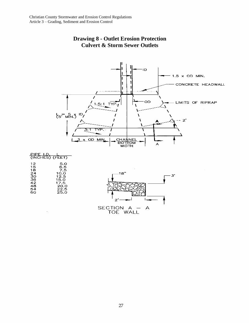
6. Storm Sewer and Culvert Outlets
Erosion protection shall be provided at storm sewer and
culvert outlets. Minimum erosion protection shall consist of
a concrete toe wall and non-erosive lining, meeting the
County’s specifications.
The required length of non-erosive lining will not be
decreased where flared end sections or headwalls are
provided unless calculations and data to support the
decrease in length are submitted and approved.
Non-erosive lining shall consist of riprap, unless otherwise
specified and approved. Field stone, gabions, or Riprap
shall extend to the point at which average channel velocity
for the peak flow rate from the minor (5-year) storm has
decreased to 5 feet per second maximum.
The length of riprap to be provided shall be as follows:
(See Drawing 8.)
Average outlet velocity less than 5 feet per second:
L = 3 times the pipe diameter or culvert width.
Average outlet velocity less than 5-10 feet per second:
L = length determined using Drawing 8.
Average outlet velocity greater than 10 feet per second:
Use MoDOT standard energy dissipater headwall.
(Reference 17.)
The height of erosion protection shall be as shown in
Drawing 8.
Minimum toe wall dimensions are shown in Drawing 8.
Where headwalls or flared end sections are specified, toe
walls must be provided at the downstream end.

Christian County Stormwater and Erosion Control Regulations
Article 3 – Grading, Sediment and Erosion Control
16
7. Curb Openings
Where drainage has been approved by the County to flow
from paved areas to grass areas through curb openings
erosion protection shall be provided as shown in Drawing
9.
8. Ditch Checks & Drop Structures
In grass channels grades and velocities may be controlled
by use of ditch checks and drop structures.
Riprap ditch checks may be required in natural channels
where average velocity for the peak flow rate from the 5-
year storm exceeds 5 feet per second for post-development
conditions.
9. Spillways
Erosion protection must be provided at spillways and outlet
structures for detention ponds. Erosion protection shall
extend to the point where flow has stabilized and average
velocity in the outlet channel is 5 feet per second or less.
10. Temporary Construction Entrance
A minimum of one temporary construction entrance is
required at each site. Additional temporary entrances may
be provided if approved. The location of each construction
entrance shall be shown on the plan.
Only construction entrances designated on the sediment
and erosion control plan may be used. Barricades shall be
maintained if necessary to prevent access at other points
until construction is complete.
Construction entrances shall be constructed of crushed
limestone meeting the following specifications:
Construction entrances shall be a minimum of 25 feet wide
and 50 feet long.
Minimum thickness of crushed limestone surface shall be
6". Additional 2" lifts of crushed limestone shall be added
at the discretion of the County if the surface of the initial
drive deteriorates or becomes too muddy to be effective.
In locations where an existing drive or street extends at
least 50 feet into the site, the existing drive may be
designated as the construction entrance, and construction of
a new gravel entrance is not required, unless job conditions
warrant as set forth in the preceding paragraph.
Christian County Stormwater and Erosion Control Regulations
Article 3 – Grading, Sediment and Erosion Control
17
11. Cleaning Streets
Streets both interior and adjacent to the site shall be
completely cleaned of sediment at the end of construction
and prior to release of security.
12. Dust Control
The contractor will be required to use water trucks to water
all roads and construction areas to minimize dust leaving
the site when conditions warrant.
13. Sequencing and Scheduling
Costs of sediment and erosion control can be minimized if
proper consideration is given to sequencing and scheduling
construction.
Any special sequencing and scheduling considerations
should be noted in the grading plan.
Christian County Stormwater and Erosion Control Regulations
Article 3 – Grading, Sediment and Erosion Control
18
Drawing 1 - Seed & Mulch Specifications
Christian County Stormwater and Erosion Control Regulations
Article 3 – Grading, Sediment and Erosion Control
19
Drawing 2A - Sediment Basin
Christian County Stormwater and Erosion Control Regulations
Article 3 – Grading, Sediment and Erosion Control
20
Drawing 2B - Berm & Outlet Structures
Christian County Stormwater and Erosion Control Regulations
Article 3 – Grading, Sediment and Erosion Control
21
Drawing 3A - Diversion Dike & Swale

Christian County Stormwater and Erosion Control Regulations
Article 3 – Grading, Sediment and Erosion Control
22
Drawing 3B - Riprap Outlet Sediment Filter

Christian County Stormwater and Erosion Control Regulations
Article 3 – Grading, Sediment and Erosion Control
23
Drawing 4A - Straw Bale Dike
Christian County Stormwater and Erosion Control Regulations
Article 3 – Grading, Sediment and Erosion Control
24
Drawing 4B - Silt Fence
Christian County Stormwater and Erosion Control Regulations
Article 3 – Grading, Sediment and Erosion Control
25
Drawing 5 - Riprap Chute
Drawing 6 - Perforated Pipe Outlet

Christian County Stormwater and Erosion Control Regulations
Article 3 – Grading, Sediment and Erosion Control
26
Drawing 7 - Sod Channel <15' & >15"
Christian County Stormwater and Erosion Control Regulations
Article 3 – Grading, Sediment and Erosion Control
27
Drawing 8 - Outlet Erosion Protection
Culvert & Storm Sewer Outlets

Christian County Stormwater and Erosion Control Regulations
Article 3 – Grading, Sediment and Erosion Control
28
Drawing 9 - Curb Opening
Christian County Stormwater and Erosion Control Regulations
Article 4 – Ownership and Maintenance
29
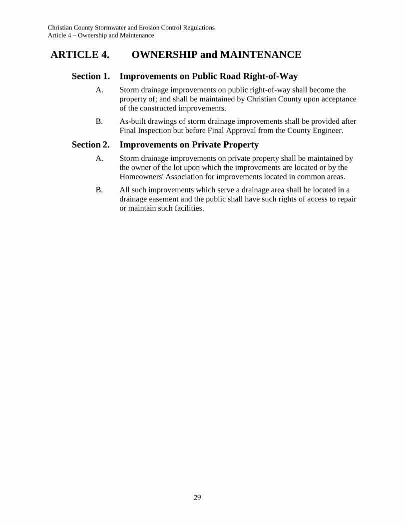
ARTICLE 4. OWNERSHIP and MAINTENANCE
Section 1. Improvements on Public Road Right-of-Way
A. Storm drainage improvements on public right-of-way shall become the
property of; and shall be maintained by Christian County upon acceptance
of the constructed improvements.
B. As-built drawings of storm drainage improvements shall be provided after
Final Inspection but before Final Approval from the County Engineer.
Section 2. Improvements on Private Property
A. Storm drainage improvements on private property shall be maintained by
the owner of the lot upon which the improvements are located or by the
Homeowners' Association for improvements located in common areas.
B. All such improvements which serve a drainage area shall be located in a
drainage easement and the public shall have such rights of access to repair
or maintain such facilities.

Christian County Stormwater and Erosion Control Regulations
Article 5 – Stormwater Planning and Design
30
ARTICLE 5. STORMWATER PLANNING & DESIGN
Section 1. Stormwater Management Goals
In order to ensure protection of the general health and welfare of the citizens of Christian
County, planning, and design of stormwater management measures shall meet the
following goals:
A. Prevent damage to residential dwellings, and other building structures
from floodwaters.
B. Maintain emergency vehicle access to all areas during periods of high
water.
C. Prevent damage to roads, bridges, utilities, and other valuable components
of the community's infrastructure from damage due to flood waters and
erosion.
D. Prevent degradation of surface and groundwater quality from storm water
runoff; preserve and protect quality of the environment; and promote
conservation of the County's natural resources.
E. Minimize flood water and erosion damage to lawns, recreational facilities,
and other outdoor improvements.
F. Minimize traffic hazards from runoff carried in streets and roads.
G. Comply with applicable State and Federal laws and regulations.
H. Meet the foregoing goals in a manner which is cost effective and which
minimizes the cost of housing and development while encouraging sound
development practices.
I. Encourage innovative and cost effective planning and design of
stormwater management facilities
J. Encourage multiple purpose design of stormwater management facilities,
to provide opportunities for recreational use, and other benefits to the
community wherever possible.
The standards and criteria set forth herein provide the minimum
standards for planning and design of stormwater facilities. Where a
particular plan or design may be found to be in conflict with a
specific standard, achievement of the goals set forth above will
have precedence.

Christian County Stormwater and Erosion Control Regulations
Article 5 – Stormwater Planning and Design
31
Section 2. General Planning and Design Principles
Christian County recognizes that stormwater management is an important component of
overall land use planning.
Christian County further recognizes that proper stormwater planning significantly
reduces the long term costs to the community both in terms of infrastructure cost and
property losses due to flood damage. It is much more cost effective to prevent flood
damage by proper design and construction, than to repair and remediate problems, which
have occurred through poor planning and design.
The following general principles must be followed in preparing the grading and storm
drainage plans for all development sites:
A. Recognize the Existing Drainage System
The storm drainage system differs from other utility systems in very
important ways:
1. There is an existing natural drainage system.
2. It is only needed when runoff occurs.
3. The capacity of the system varies greatly depending upon how
much it rains.
4. The system does not have to be constructed of man-made
components in order to function.
Because of these characteristics there has been a historic inclination for
fragmented planning and design of storm drainage facilities.
Proper planning of storm drainage facilities must begin with the
recognition of the existing system, and include necessary provisions for
preserving or altering the existing system to meet the needs of proposed
development or construction.
Methods of delineating existing watercourses are outlined in Article 6.
B. Allow for Increase in Runoff Rates Due to Future Urbanization
As areas urbanize, peak rates of runoff increase significantly. Christian
County may require temporary detention and storage of increased volumes
of urban runoff in order to minimize increases in flow rates as
urbanization occurs. However, the cumulative effects of on-site detention
are difficult to predict and control, and development of comprehensive
basin-wide runoff models to determine these effects does not appear likely
in the foreseeable future.
For this reason, design of storm drainage improvements must be based
upon the assumption of fully urbanized conditions in the area under
consideration. No reduction in peak flow rates due to detention, unless an
approved runoff model has been developed for the drainage basin under
consideration. Any detention storage facilities whose effects are
considered must be located within approved drainage easements.

Christian County Stormwater and Erosion Control Regulations
Article 5 – Stormwater Planning and Design
32
C. Provide for Acceptance of Runoff from Upstream Drainage Areas
It is critical that provisions be made to receive runoff from upstream
drainage areas. Drainage easements or public right-of-way must extend to
a point where the upstream drainage area is 2 acres or less.
Drainage easements or public right-of-way must extend to the point where
existing watercourses enter the site. Where the upstream drainage area is
2 acres or less, but does not discharge onto the site through a defined
watercourse, the drainage easement shall extend to the point of lowest
elevation.
D. Provide a Means to Convey Runoff Across the Site
Stormwater shall be conveyed across the site in a system of overland
drainage ways and storm sewers. Overland drainage ways consists of
natural waterways, streets, open channels, swales, and overland flow
within drainage easements.
E. Discharge of Runoff to Downstream Properties
Concentrated runoff shall be discharged only into existing watercourses,
drainage easements, or public road rights-of-way. Where none of these
exist, a drainage easement which extends to the nearest watercourse,
drainage easement or public road right-of-way must be obtained from the
downstream property owner, and proper provisions made for conveyance
of the peak flow from the 1% Annual Probability (100-year) storm within
the drainage easement.
One of the typical results of urbanization is that diffuse surface flow or
"sheet flow" is replaced with concentrated points of discharge. Where
concentrated flows are discharged to downstream properties proper
provisions must be made to:
1. Allow the flow to spread over the same area as would have
occurred for the same rate of flow prior to the development, and
2. Reduce the rate of velocity to rates at least equal to the pre-
development values at the same rate of flow.
F. Assess Potential Downstream Flooding Problems
It is important that a determination be made of conditions in the watershed
downstream of each development site. Specifically it is important to
determine whether there are existing structures, which are subject to an
unacceptable flooding hazard.
If areas having an unacceptable flooding hazard occur downstream of a
development site, either on-site detention for peak flow control, or
mutually agreed off-site improvements will be required, as set forth in
Article 7.
Christian County Stormwater and Erosion Control Regulations
Article 5 – Stormwater Planning and Design
33
G. Assess Potential Water Quality Impacts on Receiving Waters
Sediment, erosion and other water quality controls are required as set forth
in Article 3 and Article 9.
Section 3. Drainage Easements
All areas subject to inundation during the 100-year storm must be included in drainage
easements. Specific standards for drainage easements to be provided for storm sewers,
open channels, and detention facilities are set forth in Article 7.
Christian County Stormwater and Erosion Control Regulations
Article 6 – Stormwater Runoff Calculations
34
ARTICLE 6. STORMWATER RUNOFF CALCULATIONS
This article outlines acceptable methods of determining stormwater runoff.
Section 1. General Guidelines
For watersheds with a total tributary area less than 200 acres and a one percent annual
probability (100-year) fully developed discharge less than 300 cfs, the design storm
runoff may be analyzed using the rational formula.
For watersheds with a total tributary area greater than 200 acres or with a one percent
annual probability (100-year) fully developed discharge greater than 300 cfs, the design
storm runoff shall be analyzed using an approved hydrograph method.
Section 2. Rational Formula
A. The rational formula, when properly understood and applied, can produce
satisfactory results for urban storm sewer design. The rational formula is
as follows:
Q = CIA
Where, Q = Peak discharge in cubic feet per second.
C = Runoff coefficient which is the ratio of the maximum
rate of runoff from the area to the average rate of
rainfall intensity for the time of concentration.
I = Average rainfall intensity in inches per hour for a
duration equal to the time of concentration.
A = Contributing watershed area in acres.
B. The basic assumptions made when applying the rational formula are:
1. The rainfall intensity is uniform over the basin during the entire
storm duration.
2. The maximum runoff rate occurs when the rainfall lasts as long or
longer than the basin time of concentration.
3. Runoff response characteristics are relatively uniform over the
entire basin.
4. The time of concentration is the time required for the runoff from
the most hydraulically remote part of the basin to reach the point of
interest.
C. The drainage basin should be divided into sub-basins of a size where all of
the basic assumptions apply.
Christian County Stormwater and Erosion Control Regulations
Article 6 – Stormwater Runoff Calculations
35
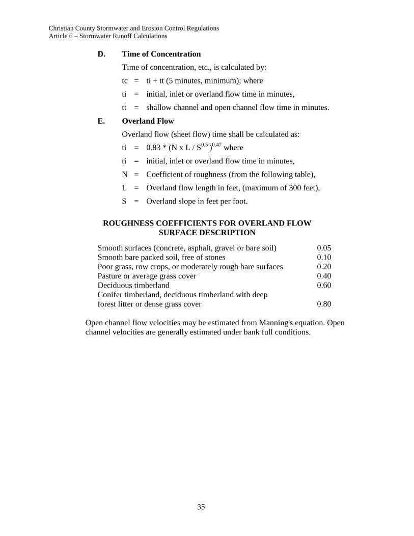
D. Time of Concentration
Time of concentration, etc., is calculated by:
tc = ti + tt (5 minutes, minimum); where
ti = initial, inlet or overland flow time in minutes,
tt = shallow channel and open channel flow time in minutes.
E. Overland Flow
Overland flow (sheet flow) time shall be calculated as:
ti = 0.83 * (N x L / S0.5
)0.47
where
ti = initial, inlet or overland flow time in minutes,
N = Coefficient of roughness (from the following table),
L = Overland flow length in feet, (maximum of 300 feet),
S = Overland slope in feet per foot.
ROUGHNESS COEFFICIENTS FOR OVERLAND FLOW
SURFACE DESCRIPTION
Smooth surfaces (concrete, asphalt, gravel or bare soil) 0.05
Smooth bare packed soil, free of stones 0.10
Poor grass, row crops, or moderately rough bare surfaces 0.20
Pasture or average grass cover 0.40
Deciduous timberland 0.60
Conifer timberland, deciduous timberland with deep
forest litter or dense grass cover 0.80
Open channel flow velocities may be estimated from Manning's equation. Open
channel velocities are generally estimated under bank full conditions.
Christian County Stormwater and Erosion Control Regulations
Article 6 – Stormwater Runoff Calculations
36
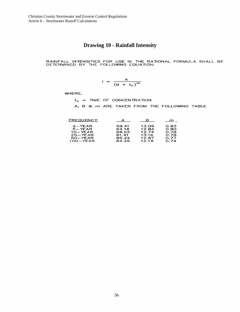
Drawing 10 - Rainfall Intensity
Christian County Stormwater and Erosion Control Regulations
Article 6 – Stormwater Runoff Calculations
37
Section 3. Hydrograph Methods
A. Methodologies
The most common hydrograph techniques are those developed by the
Corps of Engineers and the Soil Conservation Service. These methods are
preferred, however other proven techniques will be accepted.
The Corps of Engineers HEC-HMS, HEC-1 Flood Hydrograph Package,
and Soil Conservation Service TR-55 computer models are the preferred
runoff models. Other models may be used with approval from the County.
The runoff model must include the entire drainage basin upstream of the
proposed development. The model shall be prepared in sufficient detail to
ensure that peak runoff rates are reasonably accurate.
The runoff model shall be developed for the following cases:
Case 1: Existing conditions in the drainage basin prior to development
of the applicant's property.
Case 2: Existing conditions in the drainage basin with developed
conditions on the applicant's property.
Case 3: Fully developed conditions in the entire drainage basin.
B. Rainfall
Rainfall depth-duration-frequency and intensity-duration-frequency curves
for the Christian County area are included in the standard drawings. The
design rainfall intensities were developed from the U.S. Department of
Commerce, National Weather Service, Technical Paper 40 (reference 19)
and the National Oceanic and Atmospheric Administration publication
"HYDRO-35" (reference 9).
Rainfall depths for use with hydrograph techniques shall be taken from
“Rainfall Frequency atlas of the Midwest, Bulletin 71” (reference 23).
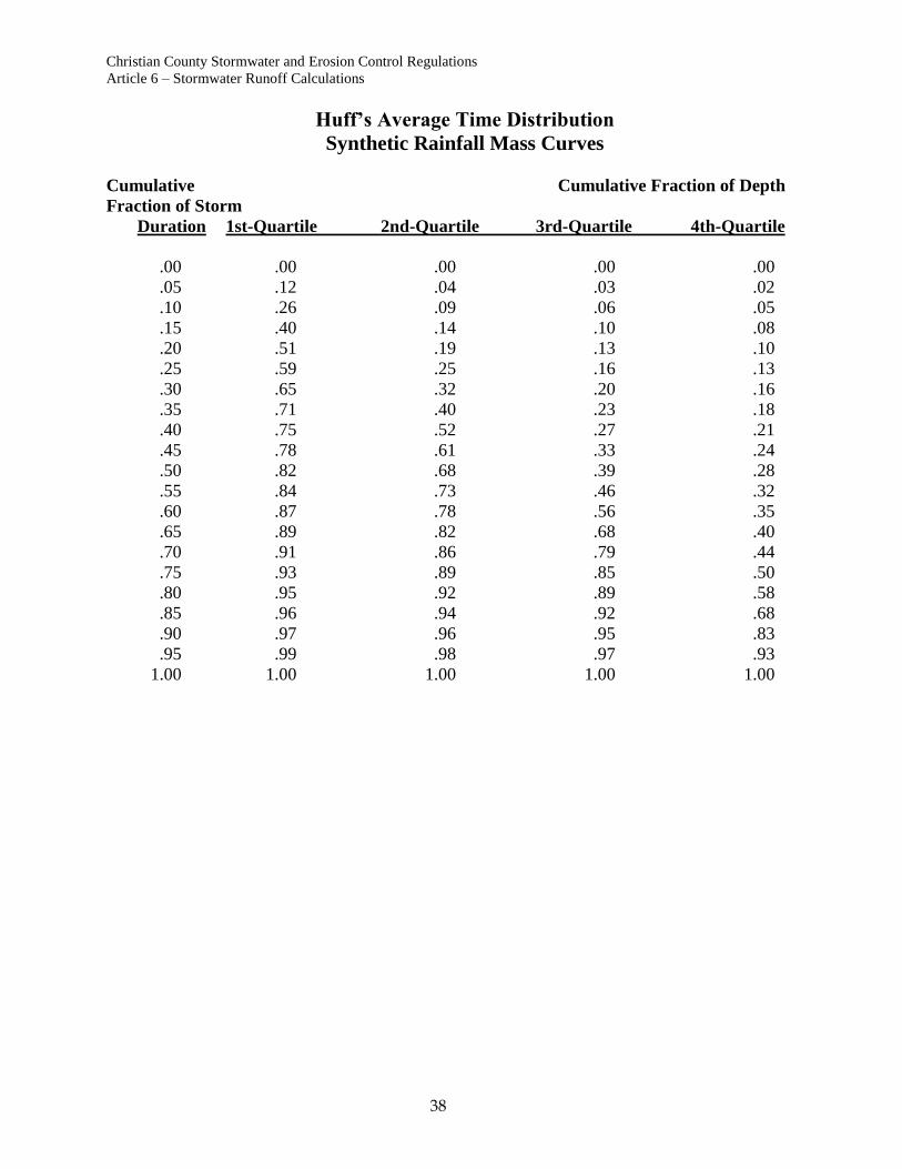
Rainfall shall be distributed in time using Huff’s Distribution adapted to
local rainfall data (references 20) as shown in the following table. Other
distributions may be used upon approval from the County.
C. Storm Duration
A critical duration analysis of storm duration and corresponding rainfall
depth shall be conducted to determine the storm duration producing the
greatest peak flow from a particular watershed. The critical duration
storm shall be used in all subsequent runoff calculations.
Christian County Stormwater and Erosion Control Regulations
Article 6 – Stormwater Runoff Calculations
38
Huff’s Average Time Distribution
Synthetic Rainfall Mass Curves
Cumulative Cumulative Fraction of Depth
Fraction of Storm
Duration 1st-Quartile 2nd-Quartile 3rd-Quartile 4th-Quartile
.00 .00 .00 .00 .00
.05 .12 .04 .03 .02
.10 .26 .09 .06 .05
.15 .40 .14 .10 .08
.20 .51 .19 .13 .10
.25 .59 .25 .16 .13
.30 .65 .32 .20 .16
.35 .71 .40 .23 .18
.40 .75 .52 .27 .21
.45 .78 .61 .33 .24
.50 .82 .68 .39 .28
.55 .84 .73 .46 .32
.60 .87 .78 .56 .35
.65 .89 .82 .68 .40
.70 .91 .86 .79 .44
.75 .93 .89 .85 .50
.80 .95 .92 .89 .58
.85 .96 .94 .92 .68
.90 .97 .96 .95 .83
.95 .99 .98 .97 .93
1.00 1.00 1.00 1.00 1.00

Christian County Stormwater and Erosion Control Regulations
Article 7 – Stormwater Drainage Structures
39
ARTICLE 7. STORMWATER DRAINAGE STRUCTURES
Section 1. Inlets
A. Inlet Locations
Inlets shall be provided at locations and intervals, and shall have a
minimum inflow capacity such that maximum flooding depths set below
are not exceeded for the specified storm; at all sump locations where
ponding of water is not desired, and where drainage cannot be released at
the ground surface.
B. Inlet Interception Capacities
Inlet capacities shall be determined in accordance with the Federal
Highway Administration HEC-12 & HEC-22 Manuals (reference 5).
Nomographs and methods presented in the Neenah Inlet Grate Capacities
report (reference 12) may also be used where applicable.
The use of commercial software utilizing the methods of HEC-12 & HEC-
22 is acceptable. It is recommended that software be pre-approved for use
by the County.
C. Clogging Factors
The inlet capacities determined as required in this section must be reduced
as follows, in order to account for partial blockage of the inlet with debris:
INLET TYPE & LOCATION CLOGGING FACTOR
Type SS Curb Opening Inlets
on grades 0.9
in sumps. 0.8
Grated Inlets:
on grades 0.6
in sumps 0.5
Inlet lengths or areas shall be increased as required to account for
clogging.
D. Interception and Bypass Flow
It is generally not practical for inlets on slopes to intercept 100% of the
flow in gutters. Inlets must intercept sufficient flow to comply with street
flooding depth requirements. Bypass flows shall be considered at each
downstream inlet, until all flow has entered approved storm sewers or
drainage ways.

Christian County Stormwater and Erosion Control Regulations
Article 7 – Stormwater Drainage Structures
40
E. Allowable Street Depth
Urban streets are a necessary part of the County drainage system. The
design for the collection and conveyance of storm water runoff is based on
a reasonable frequency and degree of traffic interference. Depending on
the street classification, (ie: local, collector, etc.) portions of the street may
be inundated during storm events. Drainage of streets are controlled by
both minor (2-year) and major (25-year) storm events. The minor system
is provided to intercept and convey nuisance flow. Flow depths are limited
for the major storm to provide for access by emergency vehicles during
most flood events. When the depths of flow exceed the criteria presented
in this section a storm sewer or open channel system is required.
F. General Design Guidelines
Allowable Flow Depths: Flow in the street is permitted with maximum
allowable depths as follows:
1. On Grades
a. Local streets: crown of the street for the runoff from a 2
year rainfall, top of curb for runoff from a 25 year rainfall.
Runoff from a 100-year rainfall should be contained within
the right-of-way.
b. Collector streets: the equivalent of one ten foot driving
lane must remain clear of water during a 2 year rainfall, top
of curb for runoff from a 25 year rainfall. Runoff from a
100-year rainfall should be contained within the right-of-
way.
c. Arterials and Parkways: two ten foot lanes must remain
clear of water, one in each direction, during a 2 year
rainfall. Top of curb for runoff from a 25-year rainfall.
Runoff from a 100-year rainfall should be contained within
the right-of-way.
2. In Sumps
a. Local streets: top of curb from a 2-year rainfall. Runoff
from a 25-year rainfall should be contained within the
right-of-way. Maximum depth from a 100-year rainfall is
18” at the face of curb.
b. Collector streets: top of curb from a 2-year rainfall. Runoff
from a 25-year rainfall should be contained within the
right-of-way. Maximum depth from a 100-year rainfall is
18” at the face of curb.
c. Arterials and Parkways: Width of gutter from a 2-year
rainfall. Runoff from a 25-year rainfall should be
contained within the right-of-way. Maximum depth from a
100-year rainfall is 18” at the face of curb.

Christian County Stormwater and Erosion Control Regulations
Article 7 – Stormwater Drainage Structures
41
Where allowable depths are exceeded a storm sewer system
must remove the excess water.
3. Cross Flow
Cross flow at intersections is permitted up to the following depth.
STREET 2-YEAR STORM 25-YEAR STORM
CLASSIFICATION ALLOWABLE DEPTH ALLOWABLE DEPTH
LOCAL 6" in cross pan flow line 12" at gutter
COLLECTOR No cross flow permitted 6" at gutter
ARTERIAL OR No cross flow No cross flow
PARKWAY permitted permitted
4. Hydraulics
The allowable storm capacity of each street section with curb and
gutter is calculated using the modified Manning's formula for both
the 2-year and 25-year storm event.
Q = 0.56(Z/n)S1/2
d8/3
Where, Q = discharge in cubic feet per second
Z = cross slope of the street in feet per foot
d = depth of flow at the gutter in feet
S = longitudinal slope of the street in feet per foot
n = Manning's roughness coefficient
Christian County Stormwater and Erosion Control Regulations
Article 7 – Stormwater Drainage Structures
42
Drawing 11 - Curb Inlet Detail

Christian County Stormwater and Erosion Control Regulations
Article 7 – Stormwater Drainage Structures
43
G. Types of Inlets Allowed
1. Public Streets
a. Curb Opening Inlets
Type "SS" standard curb opening inlets as shown in
Drawing 11 shall be used for public streets with curb and
gutter.
b. Grated Inlets
In general the use of grated inlets in streets, which require
adjustment when streets are repaved, will not be permitted.
Where conditions are such that curb inlets cannot intercept
the required rate of flow, necessary to control street
flooding depth or to provide diversion of flow to detention,
sedimentation, or infiltration basins, "trench inlets" with
veined grates may be specified with approval of the
County.
Other types of inlets will not be permitted unless approved
by the County.
2. Outside of Public Right-of-Way
The type of inlets specified outside of public right-of-way is left to
the discretion of the designer provided the following criteria are
met:
a. Maximum flooding depths for the major or minor storm as
set forth above are not exceeded.
b. General safety requirements set forth below are met.
c. All inlets shall be depressed a minimum of 2" below the
surrounding grade to allow proper drainage to the inlet and
prevent inadvertent ponding in the area around the inlet.
d. Inlets in pavements shall be provided with a concrete
apron.
H. General Safety Requirements
All inlet openings shall:
1. provide for the safety of the public from being swept into the storm
drainage system; the maximum allowable opening shall not exceed
6" in width.
2. be sufficiently small to prevent entry of debris which would clog
the storm drainage system;
3. be sized and oriented to provide for safety of pedestrians,
bicyclists, etc.

Christian County Stormwater and Erosion Control Regulations
Article 7 – Stormwater Drainage Structures
44
Section 2. Storm Sewers
A. Design Criteria
1. Design Storm Frequency
The storm sewer system, beginning at the upstream end with inlets,
is required when the 5-year peak flow in the street exceeds 5 cfs or
when allowable street depths are exceeded. Allowable street
depths are specified above.
2. Construction Materials
Storm sewers may be constructed using reinforced concrete,
corrugated metal (steel or aluminum) or plastic pipe. The
materials, pipes, or appurtenances shall meet one or more of the
following standards:
PIPE MATERIAL STANDARD
Reinforced Concrete Pipe-Round ASTM C-76 or AASHTO M-170
Reinforced Concrete Pipe-Elliptical ASTM C-507 or AASHTO M-207
Reinforced concrete Pipe-Joints ASTM C-443 or AASHTO M-198
Reinforced Concrete Pipe-Arch ASTM C-506 or AASHTO M-206
Pre-cast Concrete Manholes ASTM C-478 or AASHTO M-199
Pre-cast Concrete Box Pipe ASTM C-789/C-850 or
Corrugated Steel Pipe-Metallic AASHTO M-259/M-273
Coated for Sewers and Drains AASHTO M-36
Corrugated Aluminum Alloy Pipe
and Under drains AASHTO M-196
Bituminous Coated Corrugated Metal
Pipe and Pipe Arches AASHTO M-190
Corrugated PVC Pipe ASTM D-3034 and ASTM F-679
Corrugated Polyethylene Pipe ASTM D-1248
3. Vertical Alignment
The sewer grade shall be such that a minimum cover is maintained
to withstand AASHTO HS-20 loading on the pipe. The minimum
cover depends upon the pipe size, type and class, and soil bedding
condition, but shall not be less than 1 foot from the top of pipe to
the finished grade at any point along the pipe. If the pipe
encroaches on the street subgrade, approval is required. Manholes
will be required whenever there is a change in size, direction,
elevation grade and slope or where there is a junction of two or
more sewers. The maximum spacing between manholes for storm
sewers (cross sectional area less than 25 square feet) shall be 400
feet. For large storm sewers (cross sectional area greater than 25
square feet), manholes for maintenance access need only be placed
a minimum of every 500 feet; access to the laterals can be obtained
from within the larger storm sewer.

Christian County Stormwater and Erosion Control Regulations
Article 7 – Stormwater Drainage Structures
45
The minimum clearance between storm sewer and water main (for
new construction), either above or below shall be 12 inches.
Concrete encasement of the water line will be required for
clearances of 12 inches or less when the clearance between
existing water mains cannot be obtained.
The minimum clearance between storm sewer and sanitary sewer
(for new construction), either above or below, shall be 18 inches.
In addition, when an existing sanitary sewer main lies above a
storm sewer, or within 18 inches below, the sanitary sewer shall
have an impervious encasement or be constructed of structural
sewer pipe for a minimum of 10-feet on each side of the storm
sewer crossing.
Siphons or inverted siphons are not allowed in the storm sewer
system.
4. Horizontal Alignment
Storm sewer alignment between manholes shall be straight
except when approved by the County. Approved
curvilinear storm sewers may be constructed by using
radius pipe. The radius requirement for pipe bends is
dependent upon the manufacturer's specifications.
A minimum horizontal clearance of 10 feet is required between
sanitary and water utilities and the storm sewer.
The permitted locations for storm sewer within a street ROW are:
(a) on centerline, (b) between centerline and curb and (c) behind
the curb. Storm sewer shall not be placed on the area within the
wheel lanes of the pavement.
5. Pipe Size
The minimum allowable pipe size for storm sewers is dependent
upon a diameter practical from the maintenance standpoint. For
storm sewers less than 50 feet in length the minimum allowable
diameter is 15 inches. All other pipe shall have a minimum
diameter of 18 inches.
6. Storm Sewer Capacity and Velocity
Storm sewers should be designed to convey the design storm (25-
year) flood peaks without surcharging the storm sewer. The sewer
may be surcharged during larger floods and under special
conditions when approved by the County.
The use of storm sewers in areas without overland relief upon is
discouraged. If this situation is unavoidable, 100-year capacity
shall be provided in the storm sewer system.
Christian County Stormwater and Erosion Control Regulations
Article 7 – Stormwater Drainage Structures
46
The capacity and velocity shall be based on the Manning's n-values
presented in Table I. The maximum full flow velocity shall be less
than 15 fps. Higher velocities may be approved by the County if
the design includes adequate provisions for uplift forces, dynamic
impact forces, and abrasion. The minimum velocity in a pipe
based on full flow shall be 2.5 fps; and the minimum slope shall be
0.50% to avoid excessive accumulations of sediment. The energy
grade line (EGL) for the design flow shall be no more than six
inches below the final grade at manholes, inlets, or other junctions.
To insure that this objective is achieved, the hydraulic grade line
(HGL) and the energy grade line (EGL) shall be calculated by
accounting for pipe friction losses and pipe form losses. Total
hydraulic losses will include friction, expansion, contraction, bend,
manhole, and junction losses. The methods for estimating these
losses are presented in the following sections.
7. Storm Sewer Outlets
All storm sewer outlets into open channels shall be constructed
with a headwall and wingwalls or a flared-end-section. Riprap or
other approved material shall be provided at all outlets.
8. Hydraulic Evaluation
Presented in this section are the general procedures for hydraulic
design and evaluation of storm sewers. The user is assumed to
possess a basic working knowledge of storm sewer hydraulics and
is encouraged to review textbooks and other technical literature
available on the subject.
9. Pipe Friction Losses
Pipe friction losses are estimated using Equation 1001 and
Manning's formula (Equation 1002) which are expressed as
follows:
Hf = Sf x L (1001)
Where, Hf = head loss due to friction (feet)
Sf = friction slope from Manning's equation
(feet per foot)
L = length of pipe segment (feet)
and V = 1.49 x R2/3
x Sf1/2
/n (1002)
Where, V = velocity of flow (feet per second)
R = hydraulic radius = A/WP (feet)
Sf = friction slope (feet per foot)
A = area of flow (square feet)
WP = wetted perimeter (feet)

Christian County Stormwater and Erosion Control Regulations
Article 7 – Stormwater Drainage Structures
47
n = Manning's roughness coefficient (Table I)
10. Pipe Form Losses
Generally, between the inlet and outlet, the flow encounters, in the
flow passageway, a variety of configuration such as changes in
pipe size, branches, bends, junctions, expansions, and contractions.
These shape variations impose losses in addition to those resulting
from pipe friction. Form losses are the result of fully developed
turbulence and can be expressed as follows:
HL = K (V2/2g) (1003)
Where, HL = head loss (feet)
K = loss coefficient
V2/2g = velocity head (feet)
g = gravitational acceleration (32.2 ft/sec2).
The following is a discussion of a few of the common types of
form losses encountered in storm design.
11. Expansion Losses
Expansion losses in a storm sewer will occur when the sewer
outlets into a channel. The expansion will result in a shearing
action between the incoming high velocity jet and the surrounding
outlet boundary. As a result, much of the kinetic energy is
dissipated by eddy currents and turbulence. The loss head can be
expressed as:
HL = Kx (V12/2g)(1-(A1/A2))
2, (1004)
Where, A = cross section area in square feet
V1 = average upstream pipe flow velocity, feet per second
Kx = expansion loss coefficient.
Subscripts 1 and 2 denote the upstream and downstream sections
respectively. The value of Kx is about 1.0 for a sudden expansion
(such as an outlet to a channel) and about 0.2 for a well-designed
expansion transition. Table II presents the expansion loss
coefficient for various flow conditions.

Christian County Stormwater and Erosion Control Regulations
Article 7 – Stormwater Drainage Structures
48
12. Contraction Losses
The form loss due to contraction is:
HL = Kc(V22/2g)(1-(A2/A1)
2)2 (1005)
Where, Kc = Contraction loss coefficient
Kc is equal to 0.5 for a sudden contraction and about 0.1 for a
well-designed transition. Subscripts 1 and 2 denote the upstream
and downstream sections respectively. Table II presents the
contraction loss coefficient for various flow conditions.
13. Bend Losses
The head losses for bends in excess of that caused by an equivalent
length of straight pipe may be expressed by the relation:
HL = Kb(V2/2g) (1006)
Where, Kb = Bend coefficient
The bend coefficient has been found to be a function of: (a) the
ratio of the radius of curvature of the bend to the width of the
conduit, (b) deflection angle of the conduit, (c) geometry of the
cross section of flow, and (d) the Reynolds Number and relative
roughness. Recommended bend loss coefficients for standard
bends, radius pipe, and bends through manholes are presented in
Table II.
14. Junction and Manhole Losses
A junction occurs where one or more branch sewers enter a main
sewer, usually at manholes. The hydraulic design of a junction is
in effect the design of two or more transitions, one for each flow
path. Allowances should be made for head loss due to the
impact at junctions. The head loss at a junction for each pipe
entering the junction can be calculated from:
HL = (V22/2g) = Kj(V1
2/2g) (1007)
Where, V2 = the outfall flow velocity
V1 = the inlet velocity
Kj = junction loss coefficient
Because of the difficulty in evaluating hydraulic losses at junctions
(Reference 6) due to the many complex conditions involving pipe
size, geometry of the junction and flow combinations, a simplified
table of loss coefficients has been prepared. Table II presents the
recommended energy loss coefficients for typical manhole or
junction conditions encountered in the urban storm sewer system.
Christian County Stormwater and Erosion Control Regulations
Article 7 – Stormwater Drainage Structures
49
15. Partially Full Pipe Flow
When a storm sewer is not flowing full, the sewer acts like an open
channel and the hydraulic properties can be calculated using open
channel.
16. Storm Sewer Outlets
When the storm sewer system discharges into an open channel,
additional losses, in the form of expansions losses, occur at the
outlet. For a headwall and no wing walls, the loss coefficient Ke is
1.0. For a headwall with 45-degree wing walls, the loss
coefficient is about 1.14. For a flared-end-section (which has a
D2/D1 ratio of 2 and a theta angle of around 30 degrees) the loss
coefficient is approximately 0.5.
17. Connection Pipes
Connector pipes are used to convey runoff from an inlet to the
storm sewer. If, however, the storm sewer runs through the inlet,
then a connector pipe is not needed. Connector pipes can connect
a single inlet to the storm sewer or they can be connected in a
series.
These bends, turns, and flows through the connector pipe give rise
to three hydraulic losses: a change from static to kinetic energy to
get the water moving through the connector pipe, an entrance loss
from the inlet to the connector pipe, and a friction loss along the
length of the connector pipe. The total head loss in the connector
pipe can be calculated form the following equation:
Hcp = Hv + Ke x Hv + Sf x L (1009)
Where, Hcp = head loss in the connector pipe (feet)
Ke = Entrance loss coefficient.
Hv = velocity head in the pipe, assuming full pipe flow
(feet)
and the other variables are as previously defined. The value of the
entrance loss coefficient is determined from Table II.
If the connector pipes are connected in series, the head loss in each
pipe is calculated from Equation 1009 and the total head loss is the
summation of the individual head losses.
Christian County Stormwater and Erosion Control Regulations
Article 7 – Stormwater Drainage Structures
50
B. Easements
Easements shall be provided for all storm sewers constructed in Christian
County that are not located within public rights of way. The minimum
easement widths are as follows:
For pipes 48 inches or less in diameter or width the required easement
width is 15 feet.
For pipes and boxes greater than 48 inches in width the required easement
width is 15 feet plus half the width of the proposed storm sewer.
Storm sewers greater than 8 feet in depth to the flow line may require
additional easement width.
All easements required for construction, which are not included on the
final plat shall be recorded and filed with the County prior to approval of
the construction drawings.
Section 3. Design Standards for Culverts
A. Structural Design
All culverts shall be designed to withstand an HS-20 loading in
accordance with the design procedures of AASHTO "Standard
Specifications for Highway Bridges". The designer shall also check the
construction loads and utilize the most severe loading condition. The
minimum allowable cover is one foot.
B. Design Capacity
For drainage areas less than 1 square mile in size, culverts shall be
designed to pass the 25-year storm with one foot of freeboard prior to
overtopping the road or driveway. For drainage areas greater than 1
square mile, culverts shall be designed to pass the 100-year storm with one
foot of freeboard. In some instances, FEMA regulations may require
greater than that specified above.
C. Headwater
The maximum headwater for the major storm design flow shall be 1.5
times the culvert diameter for round culverts or 1.5 times the culvert rise
dimension for shapes other than round. In some instances, FEMA
regulations may restrict headwater to less than that specified above.
D. Inlet and Outlet Protection
For road and driveway culverts larger than 15 inches, culverts are to be
designed with protection at the inlet and outlet areas as provided in Article
3 of this criteria. Headwalls or end sections are to be located a sufficient
distance form the edge of the shoulder or the back of walk to allow for a
maximum slope of 3H:1V to the back of the structure. The type of outlet
protection required is as follows:
V < 7 FPS 7 FPS < V < 15 FPS V >15PS
Christian County Stormwater and Erosion Control Regulations
Article 7 – Stormwater Drainage Structures
51
Minimum Riprap protection Energy Riprap protection
or Dissipater Energy dissipater
E. Velocity Limitations
The maximum allowable discharge velocity is 15 feet per
second.
F. Culvert Hydraulics
It is recommended that the procedures outlined in the publication
"Hydraulic Design of Highway Culverts" reference 4 be used for the
hydraulic design of culverts. Backwater calculations demonstrating the
backwater effects of the culvert may be required.
Section 4. Design Standards for Bridges
A. Structural Design
All bridges shall be designed to withstand an HS-20 loading in accordance
with the design procedures of AASHTO "Standard Specifications for
Highway Bridges" (reference 13). The designer shall also check the
construction loads and utilize the most severe loading condition.
B. Design Capacity
Bridges shall be designed to pass the 100-year storm with one foot of
freeboard between the water surface and the bridge low chord. Bridge
capacity shall be designed such that all FEMA regulations are met.
C. Backwater
Backwater is defined as the rise in the water surface due to the constriction
created by the bridge approach road fills. The maximum backwater for
the 100-storm design flow shall be one foot. In some instances, FEMA
regulations may restrict backwater to less than that specified above.
D. Velocity Limitations
Discharge velocities through bridge openings shall be limited to 15 feet
per second. Abutment and channel scour protection shall be provided at all
bridges.
E. Bridge Hydraulics
All bridge hydraulics shall be evaluated using the procedures presented in
the publication "Hydraulics of Bridge Waterway" Reference 14.
Backwater calculations demonstrating the effects of the bridge and
approach fills compared to the existing flood stages shall be submitted for
all bridges.
Christian County Stormwater and Erosion Control Regulations
Article 7 – Stormwater Drainage Structures
52
Section 5. Design Standards for Open Channels
A. General Design Guidelines
1. Natural Channels
The hydraulic properties of natural channels vary along the
channel reach and can be either controlled to the extent desired or
altered to meet the given requirements. Natural channels used as
part of the drainage system must be evaluated for the effects of
increased peak flow, flow duration and volume of runoff due to
urbanization. A 25’ setback is required for all natural waterways.
2. Grass Lined Channels
Grass lined channels are the most desirable of the artificial
channels. The channel storage, lower velocities, and the greenbelt
multiple use benefits obtained create significant advantages over
other artificial channels. Unless existing development restricts the
availability of right of way, channels lined with grass should be
given preference over other artificial types. The minimum slope in
a grass-lined channel shall be 1.0% unless a concrete low flow
channel is installed.
3. Concrete Lined Channels
Concrete lined channels are sometimes required where right of
way restrictions within existing development prohibit grass-lined
channels. The lining must be designed to withstand the various
forces and actions, which tend to overtop the bank, deteriorate the
lining, erode the soil beneath the lining and erode unlined areas.
The minimum slope in a concrete lined channel shall be 0.50%.
4. Rock Lined Channels
Rock lined channels are constructed from ordinary riprap or wire
enclosed riprap (gabions etc.). The rock lining permits higher
design velocity than for grass lined channels. Rock linings will
normally be used only for erosion control at culvert/storm sewer
outlets, at sharp channel bends, at channel confluences and at
locally steepened channel sections.
5. Roadside Ditches
Ditches constructed alongside and in conjunction with roadways
shall be of sufficient capacity to meet the allowable street flow
depth limits as specified in this section.
6. Other Lining Types
The use of fabrics and other synthetic materials for channel linings
has increased over the past several years. Proposed improvements
of this type will be reviewed on an individual basis as for
applicability and performance.
Christian County Stormwater and Erosion Control Regulations
Article 7 – Stormwater Drainage Structures
53
B. Hydraulics
An open channel is a conduit in which water flows with a free surface.
The calculations for uniform and gradually varied flow are relatively
straightforward and are based upon similar assumptions (e.g. parallel
streamlines). The basic equations and computational procedures are
presented in this subsection.
1. Uniform Flow
Open channel flow is said to be uniform if the depth of flow is the
same at every section of the channel. For a given channel
geometry, roughness, discharge and slope, there is only one
possible depth, the normal depth. For a channel of uniform cross
section the water surface will be parallel to the channel bottom for
uniform flow.
The computation of normal depth for uniform flow shall be based
upon Manning's formula as follows:
Q = (1.49/n)AR2/3
S1/2
Where, Q = Discharge in cubic feet per second (cfs)
n = Roughness coefficient (Table I)
A = Cross sectional flow area in square feet
R = Hydraulic radius, A/P, in feet
P = Wetted perimeter in feet
S = Slope of the energy grade line (EGL) in feet/foot
For channels with a uniform cross section the EGL slope and the
bottom slope are assumed to be the same.
2. Critical Flow
The design of earth or rock channels in the critical flow regime
(Froude numbers from 0.9 to 1.2) is not permitted. The Froude
number is defined as follows:
F = V/(gD)0.5
Where, F = Froude number
V = Velocity in feet per second (fps)
g = Acceleration of gravity, 32.2 ft/sec2
D = Hydraulic depth in feet = A/T
A = Cross sectional flow area in square feet
T = Top width of flow area in feet
The Froude number shall be calculated for the design of all open
channels.
Christian County Stormwater and Erosion Control Regulations
Article 7 – Stormwater Drainage Structures
54
3. Gradually Varied Flow
The most common occurrence of gradually varied flow in storm
drainage is the backwater created by culverts, storm sewer inlets
or channel constrictions. For these conditions the flow depth will
be greater than normal depth in the channel and the water surface
profile must be computed using backwater techniques.
Backwater computations can be made using the methods presented
in Chow (reference 1). Many computer programs are available for
computation of backwater curves. The most widely used program
is HEC-RAS, Water Surface Profiles, developed by the U.S. Army
Corps of Engineers (reference 2) and is the program recommended
for backwater profile computations.
C. Design Standards
1. Flow Velocity
Maximum flow velocities shall not exceed the following:
Channel Type Max. Velocity
Grass lined* 5 fps
Concrete 15 fps
Rock Lined 10 fps
*Refer to item 6. below
2. Maximum Depth
The maximum allowable channel depth of flow is three feet for the
25-year flow.
3. Freeboard Requirements
Freeboard is defined as the vertical distance between the computed
water surface elevation for the design flow and the minimum top
of bank elevation for a given cross section. For all channels one-
foot minimum of freeboard is required. Freeboard shall be in
addition to super elevation.
4. Curvature
The minimum channel centerline radius shall be three times the top
width of the design flow.
Christian County Stormwater and Erosion Control Regulations
Article 7 – Stormwater Drainage Structures
55
5. Super Elevation
Super elevation shall be calculated for all curves. An
approximation of the super elevation h, may be calculated from
the following formula:
H = V2T/(gr)
Where, h = Super elevation in feet
V = Velocity in fps
T = Top width of flow area in feet
G = Acceleration of gravity, 32.2 ft/sec2
r = radius of curvature in feet.
Freeboard shall be measured above the super elevated water
surface.
6. Grass Channels
Side slopes shall be 3 (horizontal)to 1 (vertical) or flatter. Steeper
slopes may be used subject to additional erosion protection and
approval from the County.
For design discharges greater than 50 cfs, grade checks shall be
provided at a maximum of 200' horizontal spacing.
The variation of Manning's n with the retardance, and the product
of mean velocity and hydraulic radius as shown in Figure 7.23 in
reference 17 shall be used in the capacity calculations. Retardance
curve C shall be used to determine the channel capacity and
retardance curve D shall be used to determine the velocity.
D. Easements
Easements shall be provided for all open channels constructed in Christian
County that are not located within public rights of way. The minimum
easement width for open channels is the flow width inundated by a 100-
year event plus 15 feet.
All easements required for construction, which are not included on the
final plat shall be recorded and filed with the County prior to approval of
the construction drawings.
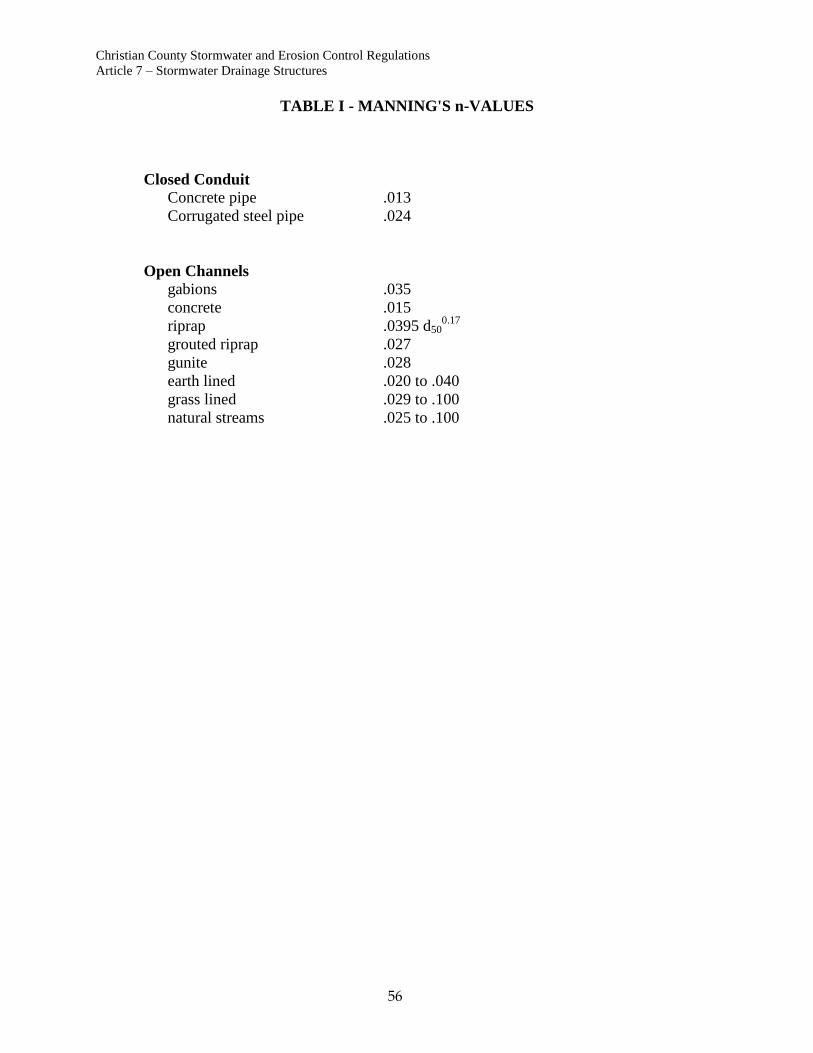
Christian County Stormwater and Erosion Control Regulations
Article 7 – Stormwater Drainage Structures
56
TABLE I - MANNING'S n-VALUES
Closed Conduit
Concrete pipe .013
Corrugated steel pipe .024
Open Channels
gabions .035
concrete .015
riprap .0395 d500.17
grouted riprap .027
gunite .028
earth lined .020 to .040
grass lined .029 to .100
natural streams .025 to .100
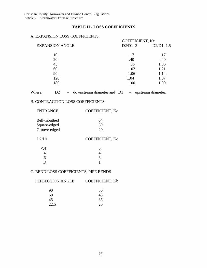
Christian County Stormwater and Erosion Control Regulations
Article 7 – Stormwater Drainage Structures
57
TABLE II - LOSS COEFFICIENTS
A. EXPANSION LOSS COEFFICIENTS
COEFFICIENT, Kx
EXPANSION ANGLE D2/D1=3 D2/D1=1.5
10 .17 .17
20 .40 .40
45 .86 1.06
60 1.02 1.21
90 1.06 1.14
120 1.04 1.07
180 1.00 1.00
Where, D2 = downstream diameter and D1 = upstream diameter.
B. CONTRACTION LOSS COEFFICIENTS
ENTRANCE COEFFICIENT, Kc
Bell-mouthed .04
Square-edged .50
Groove-edged .20
D2/D1 COEFFICIENT, Kc
<.4 .5
.4 .4
.6 .3
.8 .1
C. BEND LOSS COEFFICIENTS, PIPE BENDS
DEFLECTION ANGLE COEFFICIENT, Kb
90 .50
60 .43
45 .35
22.5 .20

Christian County Stormwater and Erosion Control Regulations
Article 7 – Stormwater Drainage Structures
58
TABLE II - LOSS COEFFICIENTS
BENDS AT MANHOLES (no special shaping)
DEFLECTION ANGLE COEFFICIENT, Kb
90 1.30
60 0.68
45 0.44
22.5 0.14
BENDS AT MANHOLES (Curved or deflector)
DEFLECTION ANGLE COEFFICIENT, Kb
90 1.04
60 0.48
45 0.32
22.5 0.10

Christian County Stormwater and Erosion Control Regulations
Article 8 – Stormwater Detention Design
59
ARTICLE 8. STORMWATER DETENTION DESIGN
Section 1. Purpose
Detention facilities are used to reduce storm water runoff rates by storing excess runoff.
The usual function of a detention facility is to provide sufficient storage such that peak
runoff rates are not increased when development occurs.
Section 2. Policy
The primary goal of the Christian County storm water management program is the
prevention of flood damage to residential, commercial and public property.
A. In adopting this policy, Christian County recognizes that:
- there are areas in the County where flooding occurs because of
inadequately sized drainage ways,
- flooding depths and frequency will increase as development occurs
upstream of these areas,
- detention basins are the only effective "on-site" means which can be
used to control peak runoff storm water rates as areas develop.
B. Christian County further recognizes that:
- the best means to assure effective performance of a detention
basin is perform reservoir routing calculations using hydrographs,
- use of the Simplified Volume Formula frequently does not
result in adequately sized detention facilities,
- the inaccuracy of the Rational Method, upon which the
Simplified Volume Formula is based, increases as the area
under consideration increases,
- even though the Simplified Volume Formula has severe
limitations, requirement of detailed analytical methods may not
be justified in all cases,
- detention basins designed using the Simplified Volume
Formula do provide a minimal amount of flooding protection
and potential water quality benefits by functioning as sediment
basins.
Therefore, in order to provide a reasonable level of flood
protection to homes and businesses, while maintaining a climate
favorable for development and economic growth, Christian County
has established the following policy for design of detention
facilities:
Christian County Stormwater and Erosion Control Regulations
Article 8 – Stormwater Detention Design
60
Section 3. Methods of Analysis
The method of analysis to be required for the design of detention facilities will be
determined as follows:
A. Detailed Analysis will be Required in the Following Cases:
1. In areas where residences or other structures located downstream
of a development can be shown to have an imminent flooding
hazard a detailed analysis using hydrographs and reservoir routing
techniques will be required.
Residences or other structures will be defined as having an
imminent flooding hazard when the lowest point, at which surface
runoff may gain entry, is located at, or below, the estimated
flooding level which would result from a storm with an annual
probability of 1% or greater under conditions existing in the basin
prior to development of the applicant's property. (i.e. affected by
the "100-year" storm)
Consideration of downstream flooding problems will be limited to
the area which may reasonably be expected to be significantly
affected by runoff from the applicant's property.
2. Detailed analysis will be required for all detention facilities where
the peak runoff rate from the area upstream of the detention facility
(off site and on site) exceeds 50 cfs (cubic feet per second) for a
storm with an annual probability of 1% (the "100-year" storm)
under fully developed conditions. (Note : This would be the rate
of flow from approximately 12 acres for residential areas or 5 acres
for fully paved commercial areas.)
B. Simplified Analysis will be Permitted in the Following Cases:
For areas where there are no imminent downstream flooding problems,
and where the peak runoff rate from the drainage area (off site and on site)
upstream of the detention facility does not exceed 50 cfs for the 1%
annual probability ("100-year") storm under fully developed conditions,
the Simplified Volume Formula may be used.
Christian County Stormwater and Erosion Control Regulations
Article 8 – Stormwater Detention Design
61
Section 4. Alternatives to Detention
A. Criteria for Approving an Alternative to Detention
The County will evaluate each request for an alternative design or
fee in lieu of detention based on the following criteria. Christian
County reserves the right to set precedent with each case
considered depending upon the unique circumstances surrounding
each request.
1. Size of site in relation to the stormwater generated.*
2. Size of the site in relation to the drainage area.*
3. Impact on properties downstream of site.*
4. Location of the site with respect to floodplains, streams or other
large watercourses.
5. Location of the site with respect to environmentally sensitive
areas.
6. Approval of previous requests.
* Downstream impacts shall generally be considered insignificant
when the added upstream impervious area is less than 10% of the
total contributing watershed area. Exceptions to this rule include
development where downstream areas are known to have an
imminent flooding hazard as defined in Article 8.
B. Residential Subdivisions
Unless otherwise approved by the County, through review of stormwater
calculations, and criteria referenced herein, detention shall be required in
all major residential subdivisions. Upon request by a developer, the
County may consider alternative in cases where it can be proven that the
absence of detention will not adversely affect downstream property
owners. Each request will be evaluated on a case-by-case basis.
C. Justified Exceptions
The County may consider, upon request, a waiver of detention for sites, in which the alteration of the site is inconsequential and will not substantially increase the runoff. A justified exception will be granted for sites based on the following criteria:
a. Existing sites in which the addition of impervious surface
will not increase more than 5,000 square feet.
b. Sites in which existing gravel, chat or stone parking lots or
driveways are paved with asphalt cement or concrete
surfaces. This shall not apply to parking areas or
circulation routes in which vegetation has consumed the
site and altered the ability to shed or absorb runoff. The
County shall exercise strict discretion with respect to
approving exceptions based on these criteria.
Christian County Stormwater and Erosion Control Regulations
Article 8 – Stormwater Detention Design
62
c. Sites in which a change in use has occurred, that does not
increase the impervious area of the site.
d. Subdivisions meeting the definition of a minor subdivision
or the development of individual single-family-residential
homes on individual lots in existing subdivisions.
D. Procedure
A request for approval of an alternative to detention must begin with the
applicant providing the County with stormwater calculations for the
increased runoff from the development. In addition to providing
calculations, the applicant must submit a request for alternative design
based on the criteria established above. The County Engineer will
coordinate review of the request with County staff. If the County
Engineer and staff determines that the request is justified the Planning &
Zoning staff will notify the applicant or his representative of the approval.
Section 5. Innovation in Design
It is the desire of the County that detention facilities be designed and
constructed in a manner to enhance aesthetic and environmental quality of
the County as much as possible.
Christian County therefore encourages designs, which utilize and enhance
natural settings, and minimize disturbance and destruction of wooded
areas, natural channels, and wetlands.
Section 6. Interpretation
Interpretations of the detention policy will be made by the County Engineer in writing.
Where disagreements may arise over the interpretation of the requirements set forth
herein, appeals may be made in accordance with procedures established by the Christian
County Zoning Regulations, the Christian County Subdivision Regulations, or the
Christian Building Regulations, as applicable.
Section 7. Design Criteria
A. General
1. Detention facilities shall discharge into a drainage easement or
public right of way.
2. One foot of freeboard shall be provided between the maximum
water surface elevation (maximum stage for a 1% annual
probability event) and the minimum top of berm or wall elevation.
3. Embankment slopes steeper than three horizontal to one vertical
(3H:1V) are not permitted.
4. In certain instances, such as when the existing development
conditions runoff from a watershed would exceed the capacity of
the existing downstream facilities, retention basins (i.e., no outlet
Christian County Stormwater and Erosion Control Regulations
Article 8 – Stormwater Detention Design
63
or with a release rate at the capacity of the downstream facilities)
for the storm runoff may be required by the County.
5. Dry detention basins shall maintain a minimum bottom slope of
two feet per hundred feet (2%).
6. Trickle channels shall have a minimum slope of one half foot per
hundred feet (0.5%).
7. The maximum allowable depth of ponding for parking lot
detention is 12 inches.
8. Parking lot detention may not inundate more than 10% of the total
parking area.
9. All parking lot detention areas shall have a minimum of two signs
posted identifying the detention pond area. The signs shall have a
minimum area of 1.5 square feet and contain the following
message:
WARNING:
This area is a storm water detention pond and is subject to
periodic flooding to a depth of 12 inches.
10. The sign shall be reflective and have a minimum height of forty-
eight (48) inches from the bottom of the sign to the parking space
finished grade. Any suitable materials and geometry of the sign
are permissible, subject to approval by the County.
B. Detailed Analysis
1. Detailed analysis shall be performed using hydrograph
methodologies and reservoir routing techniques.
2. The most common techniques are those developed by the Corps of
Engineers and the Soil Conservation Service. These methods are
preferred, however other proven techniques will be accepted.
3. Detention basins designed by detailed methods shall be designed
on the basis of multiple storm recurrence frequencies to ensure that
they function properly for both frequent storms and large
infrequent storms.
4. A minimum of three recurrence frequencies, the 50%, 10% and
1% annual probability storms (the "2-year, 10-year and 100-year"
storms) must be considered.
5. The runoff model must include the entire drainage basin upstream
of the proposed detention pond. The model shall be prepared in
sufficient detail to ensure that peak runoff rates are reasonably
accurate.
6. The runoff model shall be developed for the following cases:
Christian County Stormwater and Erosion Control Regulations
Article 8 – Stormwater Detention Design
64
Case 1: Existing conditions in the drainage basin prior to
development of the applicant's property.
Case 2: Existing conditions in the drainage basin with developed
conditions on the applicant's property.
Case 3: Fully developed conditions in the entire drainage basin.
Cases 1 & 2 are utilized to determine the required detention
volume and the type of outlet structure to be provided, and
shall be analyzed for the three storm recurrence frequencies
required above.
7. The detention facility shall be designed such that peak outflow
rates from the facility for Case 2 are no greater than the rates
determined in Case 1 for each of the three storm recurrence
frequencies required.
8. The storage volume provided shall not be less than the difference
in total runoff volume between Case 1 and Case 2.
Case 3 is used determine the size of the overflow spillway. Case 3
need only be analyzed for the 1% annual probability ("100-year").
9. The overflow spillway will, in most cases, be combined with the
outlet structure.
C. Submittals
The following information must be submitted for detention ponds
designed by detailed methods:
1. Information regarding analytical methods and software to be used,
including:
- Name of software to be used.
- Type and distribution of precipitation input.
- Method for determining precipitation losses.
- Type of synthetic hydrograph.
- Method for routing hydrographs.
- Method used for reservoir routing.
2. Map(s) showing sub-basin delineation, topography, presumed flow
routes, and pertinent points of interest; soil types; existing basin
development conditions used in the model; fully developed
conditions used in the model.
3. Routing diagram for the runoff model.
4. A summary of sub-basin characteristics used for program input.
5. Stage-area or stage-storage characteristics for the basin in tabular
or graphic form.
Christian County Stormwater and Erosion Control Regulations
Article 8 – Stormwater Detention Design
65
6. Stage-discharge characteristics for the outlet structure and
overflow spillway in tabular or graphic form; hydraulic data for
weirs, orifices, and other components of the control structure.
7. A printout of the input data file.
8. A summary printout of program output, including plots of
hydrographs. (These are intended to be the printer plots generated
by the software.)
D. Simplified Analysis
1. Method of Evaluation
Differential runoff rates shall be evaluated by equation:
R = (Cd X I100) - (Cu X I100)
Where, R = Differential Runoff Factor
Cd = Runoff Coefficient for developed conditions
Cu = Runoff Coefficient for developed conditions
I100 = Intensity for 100 year storm
"C" values shall be determined from the following table:
SUGGESTED RUNOFF COEFFICIENTS
"C" Value Surface Conditions
.10 - .15 - Tall grass, brush
.15 - .20 - Parks, golf courses, farms, and one acre single family residences
.35 - Single family residences on lots of not less than 15,000 sq. ft.
.45 - Single family residences on lots of not less than 10,000 sq. ft.
.47 - Single family residences on lots of not less than 7,500 sq. ft.
.51 - Single family residences on lots of not less than 6,000 sq. ft.
.90 - Gravel surfaces.
.95 - Asphalt and concrete surfaces.
1.00 - Buildings and other structures
Christian County Stormwater and Erosion Control Regulations
Article 8 – Stormwater Detention Design
66
E. Volume of Detention
Volume of detention shall be determined according to the "Simplified
Volume Formula", as follows:
V = R X A X tc (min.) x 60 (sec./min.)
V = Total volume of detention (cu. ft.)
R = Differential Runoff Factor
A = Area of project in acres
tc = Time of concentration (30 minutes, minimum, for volume
calculation only)
F. Time of Concentration
SCS Method
The preferred method for determining time of concentration shall be the
method set forth in Chapter 3 of the Soil Conservation Service Technical
Release No. 55, "Urban Hydrology for Small Watersheds", 2nd Edition,
1986.
Other Methods
Time of concentration may also be calculated by other accepted methods
providing reasonable results.
The time of concentration used in the formula shall be determined based
upon existing conditions.
G. Rainfall Intensity
Rainfall intensity shall be determined from Drawing 10.
H. Required Volume
The required volume of detention shall be determined from the following
Table:
Calculated Volume Required Volume
1 cu. ft. thru 500 cu. ft. 500 cu. ft.
501 cu. ft. thru 5,999 cu. ft. Round up to nearest 500 cu. ft.
5,000 cu. ft. thru 9,999 cu. ft. Round up to nearest 1,000 cu. ft.
10,000 cu. ft. thru 49,999 cu. ft. Round up to nearest 5,000 cu. ft.
Above 50,000 cu. ft. Round up to nearest 10,000 cu. ft

Christian County Stormwater and Erosion Control Regulations
Article 8 – Stormwater Detention Design
67
I. Control Structures – Simplified Analysis
1. Detention facilities designed by the simplified analysis shall be
provided with obvious and effective outlet control structures.
These outlet structures may include v-notch weirs or rectangular
weirs, as well as pipe. Plan view and sections of the structure with
adequate detail shall be included in plans.
2. The design discharge (Q) for the low-flow outlet shall not exceed
the existing runoff for the one-year storm. The maximum
discharge shall be designed to take place under total anticipated
design-head conditions. The design-head storage volume is not to
be considered a part of the volume of detention required.
3. Sizing of a low-flow pipe shall be by inlet control.
4. Low-flow pipes shall not be smaller than four (4) inches in
diameter to minimize maintenance and operating problems, except
in parking lot and roof detention where minimum size and
configuration of opening shall be designed specifically for each
condition.
5. Overflow spillways will be required on all detention facilities,
which have storage volumes of 1,000 or more cubic feet.
6. The overflow opening or spillway shall be designed so that the
combination flow of the low flow outlet and the flow over the
spillway will not exceed the total peak runoff for the improved
area. The total peak runoff is to be determined from a 100 year
storm event.

Christian County Stormwater and Erosion Control Regulations
Article 9 – Sinkholes and Karst Features
68
ARTICLE 9. SINKHOLES AND KARST FEATURES
Section 1. General
Christian County is located on or near the Springfield Plateau of the Ozark physiographic
region. This area is underlain by Mississippian Age limestone, which is highly
susceptible to solutional weathering. As a result, sinkholes, springs and caves are
common.
In many areas of the County special consideration must be given to flood hazards and
potential for groundwater contamination due to the presence of sinkholes, caves, losing
streams, springs, and other features associated with karst geology.
The requirements set forth herein, are intended to provide specific criteria for design and
construction for any site upon which sinkholes or other karst features are located.
Interpretations of these requirements shall be made and appeals may be made according
to the procedures set forth in these Design Criteria.
Section 2. Policy
In keeping with the intent of the Christian County stormwater management plan the
following policy is set forth for development in areas containing sinkholes:
A. Development in sinkhole areas will be based upon the following
axioms:
1. Avoidance
2. Minimization
3. Mitigation
B. Construction in sinkholes shall be avoided. Exceptions will be made only
in situations where it can be conclusively demonstrated that there are no
practical alternatives to such construction. These situations are mostly
likely to arise where:
1. An underground cavity has caused a collapsed sinkhole to form,
after subdivision approval or building construction.
2. A sinkhole has been altered or filled either unknowingly or prior to
passage of these regulations.
3. Maintenance and operation is required for existing roads and
utilities.
4. Location of existing streets or utilities would render access or
utility service to a property impractical or cost prohibitive.
In these types of cases, measures which will have minimal impact on the sinkhole or
receiving water may be proposed. Plans for minimal alteration can be approved provided
it is conclusively demonstrated that the proposed plan is the minimum practical
alternative.

Christian County Stormwater and Erosion Control Regulations
Article 9 – Sinkholes and Karst Features
69
In these cases potential impacts of construction on the sinkhole and receiving waters must
be studied and assessed, and recommendations made for mitigation of potential impacts
upon surface flooding and groundwater quality before the plans can be approved. The
degree and sophistication of study required will increase in proportion to the potential
impacts.
Section 3. Definitions
Sinkhole
Any depression in the surface of the ground, with or without collapse of adjacent rock
that provides a means through which surface water can come into contact with subsurface
water.
Sinkhole depressions may be gradual or abrupt; they may or may not have a well defined
eye. While most sinkholes can be defined as the area within a "closed contour", some
sinkholes such as those located on the sides of hills may not.
All sinkholes provide discreet points of recharge to groundwater.
Sinkhole Watershed
The ground surface area that provides drainage to the sinkhole. This area extends beyond
the sinkhole depression, and generally crosses property boundaries.
Unaltered Sinkhole
A sinkhole that has never been altered or disturbed.
Altered Sinkhole
A sinkhole that has been filled, excavated, or otherwise disturbed.
Collapsed Sinkhole
A subsidence or cave-in of the ground surface caused when soil overburden can no longer
be supported by underlying strata due to the presence of subsurface solution cavities.
Sinkhole Eye
Generally, a visible opening, cavity, or cave in the bottom of a sinkhole, sometimes
referred to as a swallow hole.
Sinkhole Rim
The perimeter of the sinkhole depression. The sinkhole rim will generally vary in
elevation.
Christian County Stormwater and Erosion Control Regulations
Article 9 – Sinkholes and Karst Features
70
Sinkhole Cluster Area
An area containing 2 or more sinkholes located in close proximity, generally
interconnected by groundwater conduits.
Terminal Sinkhole
The lowest sinkhole in a sinkhole cluster to which any surface water overflowing from
other sinkholes in the cluster will flow.
Sinkhole Flooding Area
The area innundated by runoff from a storm with an annual exceedance probability of 1%
and a duration of 24 hours.
Qualified Geologist
A person who has met or exceeded the minimum geological educational requirement and
who can interpret and apply geologic data principles, and concepts and who can conduct
field or laboratory geologic investigations (per RSMo); and who by reason of experience
and education, has an understanding of local karst geology.
Qualified Professional Engineer
A person registered to practice engineering according to the laws of the State of Missouri,
and who by reason of technical education and experience has a background in the
fundamentals of storm drainage and karst geology.
Heavy Equipment
Motorized equipment having a gross weight of more than 6 tons.
Light Equipment
Motorized equipment weighing 6 tons or less.
Christian County Stormwater and Erosion Control Regulations
Article 9 – Sinkholes and Karst Features
71
Section 4. Permits Required
A. Soil Erosion & Control Permit
A grading permit must be obtained prior to any alteration of sinkholes
associated with new subdivision construction in accordance with County
regulations.
Procedures and requirements for grading permits are set forth in Article 3.
B. Other permits
Other permits from State or federal agencies may be required, as outlined
in Article 1 of these Design Criteria, depending upon the size and nature
of the proposed activity.
Section 5. General Plan Requirements
General requirements for grading and drainage plans are set forth in Article 3, Article 6
and Article 7 of these Design Criteria.
Section 6. Sinkhole Evaluation
An evaluation including the following information shall be made for all sites upon which
sinkholes are fully or partially located:
A. The site plan for the proposed development must show the
following items with respect to location of proposed construction,
proposed or existing property lines, and existing structures:
1. Sinkholes
a. Location and limits of the area of the sinkhole
depression as determined by field surveys or other
reliable sources as may be approved.
Location of sinkholes based solely upon USGS 7-
1/2 Minute Series Quadrangle Maps will not be
considered sufficient unless field verified.
b. Location and elevation of the sinkhole eye where
visible or known.
c. Topographic contours at maximum intervals of 2
feet, and spot elevations sufficient to determine the
low point on the sinkhole rim and the profile of the
potential overflow area.
d. Minimum entry elevations of any existing structures
located within the sinkhole rim.
e. Elevation of any roadway located within or adjacent
to the sinkhole.

Christian County Stormwater and Erosion Control Regulations
Article 9 – Sinkholes and Karst Features
72
2. Water Supply Sources
a. The approximate location of public or private water
supply sources such as springs or wells, as
determined from information available from the
County and Missouri Department of Natural
Resources that are located within a 500’ radius of
the sinkhole.
b. Boundaries of any known recharge areas to wells or
springs as determined from information available
from the County and Missouri Department of
Natural Resources.
3. Other Geologic Features
Location of caves, springs, faults and fracture trends, geologic
mapping units based upon information from the County or other
reliable sources.
B. Flooding Limits for the Sinkholes Determined as Set Below:
1. A drainage area map showing the sinkhole watershed area.
Where the site is located in a sinkhole cluster area, this map
shall be extended to include the watershed area any
sinkholes located downstream of the site which may
receive overflow drainage from the site.
C. Assessment of potential impacts on groundwater quality and proposed
water quality management measures as set forth below.
Section 7. Flooding Considerations
A. Minimum Flooding Analysis
Maximum estimated flooding elevations shall be determined for each
sinkhole for both pre-development and post development conditions,
assuming no subsurface outflow from the sinkhole.
Where the estimated volume of runoff exceeds the volume of the sinkhole
depression, the depth, spread and path of overflow shall be estimated and
shown on the map.
The overflow volume shall be included determining the maximum
estimated flooding elevations in the next downstream sinkhole. This
analysis shall continue downstream until the lowest sinkhole of the
sinkhole cluster is reached or overflow reaches a surface watercourse.
The volume of runoff considered shall be that which results from a
rainstorm with an annual probability of 1% (100-year storm) and a
duration of 24 hours (8.2 inches).
The runoff volume shall be determined by the method set forth in Chapter
2 of the SCS TR-55 Manual (Reference).
Christian County Stormwater and Erosion Control Regulations
Article 9 – Sinkholes and Karst Features
73
No Further Flooding Analysis will be Required Provided That:
1. The post-development flooding area of any sinkhole which
receives drainage from the site is located entirely on the site.
a. A drainage easement covering the post-development
flooding area is provided for any off-site sinkhole or
portion of a sinkhole which receives increased peak rates of
runoff from the site. If the receiving sinkhole is not
contiguous to the site, an easement must also be provided
for the waterway that connects the site to the sinkhole.
2. The minimum entry elevation of any existing structure is at least 5
feet higher than the estimated flooding elevation from the 1%
annual probability 24-hour storm.
3. The flooding depth on any existing public road does not exceed the
maximum depths set forth in Article 7.
B. Detailed Flooding Analysis
In cases where the conditions set forth above cannot be met, a detailed
flooding analysis will be required if any increase in runoff volume is
proposed. For detailed flooding analysis a runoff model must be made for
the sinkhole watershed and reservoir routing analysis performed using
hydrograph techniques as set forth in Article 8
The following alternative methods may be used singly or in combination
to keep flooding levels at pre-development levels:
1. Diversion of excess runoff to surface watercourses.
Where feasible, increased post-development runoff may by
diverted to a surface watercourse, provided that
a. Any increase in peak runoff rate in the receiving
watercourse does not create or worsen existing flooding
problems downstream; and
b. The diverted storm water remains in the same surface
watershed.
Storm sewers, open channels and other appurtenances
provided for diversions shall be designed in accordance
with applicable sections of these Design Criteria.
The effect of diverted water on downstream watercourses
and developments, and requirements for additional
detention facilities prior to release of runoff to the surface
water course shall be determined as set forth in Article 8,
Detention Facilities.
Effects of the diversion shall be shown by reservoir routing
analysis. Routing of excess runoff shall be considered
satisfactory when it can be demonstrated that the post-
Christian County Stormwater and Erosion Control Regulations
Article 9 – Sinkholes and Karst Features
74
development flooding elevation in the sinkhole does not
exceed the pre-development flooding elevation within
reasonable tolerance (generally 0.1 ft.).
2. Storage of Excess Runoff Within the Sinkhole Watershed
Where feasible, detention facilities may be constructed within the
sinkhole watershed or in perimeter areas of the sinkhole. These
detention facilities must be located outside the sinkhole flooding
area determined for post-development conditions.
The flooding considerations set forth in this Section will be met if
it can be demonstrated that:
a. Inflow rates to the sinkhole can be reduced to a degree that,
in conjunction with the observed outflow rate, the post-
development flooding elevation in the sinkhole does not
exceed the pre-development flooding elevation within
reasonable tolerance (generally 0.1 ft.).
3. Sediment & erosion control and water quality considerations as set
forth elsewhere in this section can be satisfied.
Section 8. Water Quality Considerations
Sinkholes provide direct recharge routes to groundwater. As a result water quality in
wells, caves and springs may be affected by discharge of runoff from developed areas.
The Sinkhole Evaluation must consider potential impacts of the proposed construction on
receiving groundwater and propose measures to mitigate such impacts.
Four Primary Factors Must be Considered in the Sinkhole Evaluation:
1. Receiving groundwater use.
2. Relative groundwater contamination hazard associated with the
proposed development.
3. Ability to capture pollutants.
4. Management measures to be provided to reduce pollutant levels.
A. Receiving Groundwater Use
The Sinkhole Evaluation Report shall identify whether the site lies within
a critical area based upon information available from the County.
Where disagreements may arise over whether a site is located within a
particular recharge area dye tracing may be required for confirmation of
the destination of water discharges through a sinkhole.
1. Critical Areas
The following areas are classified as critically sensitive to
contamination from urban runoff:
a. Recharge areas of domestic water supply wells.
Christian County Stormwater and Erosion Control Regulations
Article 9 – Sinkholes and Karst Features
75
b. Recharge areas of springs used for public or private water
supply.
c. Recharge areas of caves providing habitat to rare or e
endangered species such as the Ozark cave fish.
2. Sensitive Areas
All other sinkhole areas will be classified as sensitive to
contamination from urban runoff.
B. Groundwater Contamination Hazard
The relative potential for groundwater contamination will be classified as
moderate, high, or very high depending upon the type of land use,
development density and amount of directly connected impervious area.
The Sinkhole Evaluation shall identify whether the proposed development
poses a moderate, high or very high hazard to groundwater uses, as
defined below:
1. Moderate Hazard
The following land uses are classified as posing a relatively low
hazard to groundwater contamination:
a. Wooded areas and lawns.
b. Parks and recreation areas.
c. Residential developments on sewer, provided directly
connected impervious areas discharging to the sinkhole is
less than 1 acre.
d. Low density commercial and office developments provided
directly connected impervious areas discharging to the
sinkhole is less than 1 acre.
e. Discharge from graded areas less than 1 acre having
required sediment controls per Article 3.
2. High Hazard
a. Concentrated discharge from streets and parking lots and
roofs and other directly connected impervious areas having
an area greater than 1 Acre and less than 5 acres.
b. Multifamily residential developments and higher intensity
office developments provided the directly connected
impervious areas discharging to the sinkhole is less than 5
acres.
c. Discharge from graded areas greater than 1 acre and less
than 5 acres having required sediment controls per Article
3.
Christian County Stormwater and Erosion Control Regulations
Article 9 – Sinkholes and Karst Features
76
3. Very High Hazard
a. Collector and arterial streets and highways used for
commercial transport of toxic materials.
b. Railroads.
c. Concentrated discharge from streets and parking lots and
roofs and other directly connected impervious areas having
an area greater than 5 acres.
d. Commercial, industrial and manufacturing areas.
e. Individual wastewater treatment systems.
f. Commercial feedlots or poultry operations.
g. Discharge from graded areas greater than 5 acres having
required sediment controls per Article 3.
C. Capturing and Filtering Pollutants
The majority of sinkholes drain a limited watershed area. For sinkholes
where the surrounding drainage area is small enough that the area
draining to the sinkhole flows predominantly as "sheet flow", potential
impacts on water quality can be addressed by erecting silt control barriers
around the sinkhole during construction and providing a vegetative buffer
area around the sinkhole to filter out potential contaminants.
When the volume of runoff into the sinkhole increases to the point where
flow becomes concentrated, the degree of effort required capturing and
filtering out contaminants increases significantly.
Concentrated inflow occurs naturally when the sinkhole watershed area
reaches a sufficient size for watercourses leading into the sinkhole to form.
Concentrated surface flows result as urbanization occurs due to
construction of roads, storm sewers, drainage channels. Subsurface flows
can become concentrated through utility trenches.
The Sinkhole Evaluation shall include maps showing any existing
watercourse which flows into the sinkhole and location of any proposed
concentrated storm water discharges into the sinkhole.
D. Water Quality Management Measures
1. Sediment and Erosion Control
a. Non-Concentrated Flow (Sheet Flow)
In critical areas, existing ground cover shall not be removed
within 30 feet of the sinkhole rim and a silt barrier shall be
provided around the outer perimeter of the buffer area.
b. Concentrated Flow
A sediment basin will be required at each point where
concentrated flows are discharged into the sinkhole.
Christian County Stormwater and Erosion Control Regulations
Article 9 – Sinkholes and Karst Features
77
Sediment basins shall be designed according to the
procedures set forth in Article 3.
2. Minimizing Directly Connected Impervious Area
The groundwater contamination hazard category for impervious
areas may be reduced by reducing the amount of Directly
Connected Impervious Area. This is the area of roofs, drives,
streets, parking lots, etc. which are connected via paved gutters,
channels, or storm sewers.
Directly Connected Impervious Areas can be reduced by providing
properly sized grass swales, vegetative filter strips, or other Best
Management Practices to separate paved areas.
3. Diversion of Runoff
Concentrated discharges to sinkholes can be reduced to
manageable levels or avoided by diverting runoff from impervious
areas away from sinkholes where possible.
Diversions shall be done in a manner that does not increase
flooding hazards on downstream properties and, generally, shall
not be directed out of the surface watershed in which the sinkhole
is located.
4. Filtration Areas
For areas having a moderate or high groundwater contamination
hazard and where flow into the sinkhole occurs as sheet flow,
water quality requirements can be satisfied by maintaining a
permanent vegetative buffer area with a minimum width of 30 feet
around the sinkhole.
Use of pesticides and fertilizers will not be permitted within the
buffer area. Animal wastes will not be permitted to accumulate in
the buffer area.
5. Grassed Swales and Channels
For areas having a moderate groundwater contamination hazard
concentrated flows from directly connected impervious areas of
less than one acre may be discharged into the sinkhole through
grassed swales and channels.
Swales and channels shall be designed for non-erosive velocities
and appropriate temporary erosion control measures such as
sodding or erosion control blankets provided.

Christian County Stormwater and Erosion Control Regulations
Article 9 – Sinkholes and Karst Features
78
6. Storage and Infiltration
Storage and infiltration will be required in the following cases:
a. All areas having a very high groundwater contamination
hazard.
b. Areas having a high groundwater contamination hazard
where concentrated inflow occurs.
Storage and infiltration basins shall be designed to capture the
runoff from storms up to 1 inch and release runoff over a
minimum period of 24 hours and maximum period of 48 hrs.
Standards outlet structures for sedimentation and infiltration basins
are shown in the standard drawings.
E. Development Requirements.
1. Stormwater Detention in Sinkholes
Where flooding considerations and water quality
considerations, as set forth in Article 3, can be met, the volume
of runoff storage in sinkholes can be counted toward storm
water detention requirements, provided that proper sediment
and erosion control measures are provided as set forth in
Article 3.
The volume of required detention storage shall be determined
as set forth in Article 8.
Excavation within the sinkhole flooding area to provide
additional detention storage will not be allowed.
2. Modification of Sinkholes to Increase Outflow Rates
Increasing outflow rates in sinkholes by excavating the
sinkhole eye or installing disposal wells for diverting surface
runoff to the groundwater system is prohibited, unless clear and
imminent danger to the public health and safety can be
demonstrated.
3. Setbacks and Use Restrictions
a. No new construction of any of the following shall be
permitted within 30 feet horizontally of the sinkhole
rim:
1. Residential, commercial or industrial structures.
2. Swimming pools.
3. Streets, highways, or parking lots.
4. Storage yards for materials, vehicles, and
equipment.
5. Sanitary sewer lines.

Christian County Stormwater and Erosion Control Regulations
Article 9 – Sinkholes and Karst Features
79
b. The finished floor elevation of all structures constructed
within a sinkhole rim shall have the finished floor set a
minimum of 5 feet above the 100-year water surface
elevation as determined in Section G above.
c. Use of pesticides and fertilizers within 30 feet of the
sinkhole rim is prohibited.
d. Use of heavy construction equipment in unaltered
sinkholes is prohibited.
e. Construction of underground utilities is prohibited within
the sinkhole rim.
f. Recreational facilities such as hiking, jogging, and
bicycling trails, playgrounds, exercise courses, and grass
playing fields are permitted within the sinkhole area
provided they are not located within the eye of the
sinkhole.
g. Golf courses are permitted subject to approval of a
Management Plan for use of pesticides and fertilizers.
h. Clearing and pruning of trees and undergrowth, and limited
grubbing of roots is permitted.
i. Landscaping and minor gardening is permitted outside of
the sinkhole eye provided erosion and sediment discharge
is limited through use of minimum tillage and mulches.
j. Construction of light incidental landscaping and
recreational structures such as gazebos, playground
equipment, etc. is permitted except in the sinkhole eye.
4. Collapsed Sinkholes
Collapsed sinkholes may be stabilized and filled using approved
techniques. A Soil Erosion & Control Permit must be issued prior
to performing any construction.
The probable cause of the collapse and potential adverse impacts
of filling the collapse shall be investigated and information
submitted with the permit application.
5. Altered Sinkholes
Filling or altering of sinkholes without a Soil Erosion & Control
Permit constitutes a violation of these regulations. In such cases
corrective measures must be proposed within the time period
specified in the Zoning Regulations for enforcement of such
violations. No corrective or remedial measures shall be undertaken
until the proposed remediation plan has been reviewed by the
County and a Permit issued.

Christian County Stormwater and Erosion Control Regulations
Article 9 – Sinkholes and Karst Features
80
No Building Permits will be issued, or zoning or subdivision
approvals granted, until the remedial measures specified in the Soil
Erosion & Control Permit have been completed and approved.

Christian County Stormwater and Erosion Control Regulations
Article 10 – Floodplain Development
81
ARTICLE 10. FLOODPLAIN DEVELOPMENT
Section 1. Purpose
As a participant in the National Flood Insurance Program, Christian County adheres to
the requirements of the 1968 Flood Insurance Act and the 1994 Flood Insurance Reform
Act. The National Flood Insurance Program (NFIP) is administered by FEMA.
The purpose of the NFIP is to:
A. Significantly limit the number of new structures built below the 100-year
flood elevation
B. Provide affordable flood insurance to existing flood prone structures
C. Provide programs to remove or elevate substantially damaged structures
and repetitive loss structures
Section 2. Policy
Christian County, through the Floodplain Manager, is responsible for reviewing and
ensuring that all development in the floodplain and floodway meets the requirements of
the NFIP.
Section 3. Definitions
Flood
Temporary condition of partial or complete inundation of normally dry areas from
overflow of inland or tidal waters, rapid accumulation or runoff of surface waters from
any source.
SFHA (Special Flood Hazard Area)
Areas subject to a 1% or greater annual chance of flooding in a given year.
BFE (Base Flood Elevation)
The flood elevation from a flood having a 1% probability of being equaled or exceed in
any given year.
FIRM (Flood Insurance Rate Map)
Official map of a community on which FEMA has delineated the flood hazard areas.
FIS (Flood Insurance Study)
An engineering study performed under contract to FEMA to identify floodprone areas
and to determine BFEs.

Christian County Stormwater and Erosion Control Regulations
Article 10 – Floodplain Development
82
Structure
A walled and roofed building, including a gas or liquid storage tank, that is principally
above ground.
Floodway
The critical area of the SFHA that must be preserved to allow passage of floods.
Surcharge
The difference in the elevation of the base flood and the floodway water surface elevation
at a given point. This value is never more than 1.0 foot.
Fringe
The area of the SFHA between the floodway and the 100-year flooding limits.
Encroachment
Any fill, structures or other obstructions that infringe upon the floodway or floodplain
and cause an increase in the BFE.
Section 4. Permits
A floodplain development permit is required for all development or fill activities within
the limits of the 100-year floodplain as shown on the FIRM.
Section 5. FEMA
Prior to approval of any development plan, all lots or structures to be located within the
floodplain or floodway must meet all NFIP requirements.
A. Approximate Zone A
1. Establishment of BFEs in an approximate Zone A floodplain must
conform to the requirements of, The Zone A Manual: Managing
Floodplain Development in Approximate Zone A Areas.
2. Based upon the computed BFE, a Letter of Map Amendment or
Letter of Map Revision Based upon Fill must be obtained from
FEMA for the property and/or structure in question.
3. Encroachment in an approximate Zone A floodplain must produce
no more than 1.0 foot of rise in the BFE.
B. Zone AE
1. Based upon the BFEs from the FIRM, a Letter of Map Amendment
or a Letter of Map Revision Based upon Fill must be obtained from
FEMA for the property and/or structure in question.
Christian County Stormwater and Erosion Control Regulations
Article 10 – Floodplain Development
83
2. If mapping errors are found or changes to BFEs are proposed, a
Letter of Map Revision must be obtained from FEMA for the
floodplain reach impacted.
C. Floodway Development
1. Development causing any obstruction to flow is not allowed within
the effective floodway.
2. A No-Rise Certification must be made for all roadway crossings of
the floodway.
3. If changes to the floodway are desired, a Letter of Map Revision
must be obtained from FEMA for the floodway reach impacted.
Christian County Stormwater and Erosion Control Regulations
Appendix A – Adopted Floodplain Management Ordinance
84
APPENDIX A ADOPTED FLOODPLAIN MANAGEMENT
ORDINANCE
Christian County Stormwater and Erosion Control Regulations
Appendix A – Adopted Floodplain Management Ordinance
85
Christian County Stormwater and Erosion Control Regulations
Appendix A – Adopted Floodplain Management Ordinance
86
Christian County Stormwater and Erosion Control Regulations
Appendix A – Adopted Floodplain Management Ordinance
87

Christian County Stormwater and Erosion Control Regulations
Appendix A – Adopted Floodplain Management Ordinance
88
Christian County Stormwater and Erosion Control Regulations
Appendix A – Adopted Floodplain Management Ordinance
89
Christian County Stormwater and Erosion Control Regulations
Appendix A – Adopted Floodplain Management Ordinance
90

Christian County Stormwater and Erosion Control Regulations
Appendix A – Adopted Floodplain Management Ordinance
91
Christian County Stormwater and Erosion Control Regulations
Appendix A – Adopted Floodplain Management Ordinance
92
Christian County Stormwater and Erosion Control Regulations
Appendix A – Adopted Floodplain Management Ordinance
93

Christian County Stormwater and Erosion Control Regulations
Appendix A – Adopted Floodplain Management Ordinance
94
Christian County Stormwater and Erosion Control Regulations
Appendix A – Adopted Floodplain Management Ordinance
95
Christian County Stormwater and Erosion Control Regulations
Appendix A – Adopted Floodplain Management Ordinance
96
Christian County Stormwater and Erosion Control Regulations
Appendix A – Adopted Floodplain Management Ordinance
97
Christian County Stormwater and Erosion Control Regulations
Appendix A – Adopted Floodplain Management Ordinance
98
Christian County Stormwater and Erosion Control Regulations
Appendix A – Adopted Floodplain Management Ordinance
99

Christian County Stormwater and Erosion Control Regulations
Appendix A – Adopted Floodplain Management Ordinance
100
Christian County Stormwater and Erosion Control Regulations
Appendix A – Adopted Floodplain Management Ordinance
101
Christian County Stormwater and Erosion Control Regulations
Appendix A – Adopted Floodplain Management Ordinance
102

Christian County Stormwater and Erosion Control Regulations
Appendix A – Adopted Floodplain Management Ordinance
103
Christian County Stormwater and Erosion Control Regulations
Appendix B – Adopted Illicit Discharge Management Ordinance
104
CHRISTIAN COUNTY COMMISSION
AN ORDER REGULATING
ILLICIT DISCHARGE AND ILLEGAL CONNECTION TO STORM DRAINAGE
SYSTEMS AND PROVIDING PENALTIES
Authority: Section 192.300. The county commissions and the county health center boards of the
several counties may make and promulgate orders, ordinances, rules or regulations, respectively
as will tend to enhance the public health and prevent the entrance of infectious, contagious,
communicable or dangerous diseases into such county, but any orders, ordinances, rules or
regulations shall not be in conflict with any rules or regulations authorized and made by the
department of health and senior services in accordance with this chapter or by the department of
social services under chapter 198. The county commissions and the county health center boards
of the several counties may establish reasonable fees to pay for any costs incurred in carrying out
such orders, ordinances, rules or regulations, however, the establishment of such fees shall not
deny personal health services to those individuals who are unable to pay such fees or impede the
prevention or control of communicable disease.
Section 1: Purpose and Intent
The purpose of this chapter is to protect the public health, safety, environment, and general
welfare through the regulation of Non-Stormwater Discharges to the County’s Separate Storm
Sewer System or into any Waters of the United States to the maximum extent practicable as
required by federal law. This chapter establishes methods for controlling the introduction of
Pollutants into the County’s Separate Storm Sewer System in order to comply with requirement
of the National Pollutant Discharge Elimination System (NPDES) permit process. The objectives
of this chapter are to:
a. Regulate the contribution of Pollutants to the County’s Separate Storm Sewer System or
into any Waters of the United States by any Person;
b. Prohibit Illicit Discharges and Illegal Connections to the County’s Separate Storm Sewer
System or into any Waters of the United States;
c. Prevent Non-Stormwater Discharges, generated as a result of spills, inappropriate
dumping, or disposal, into the County’s Separate Storm Sewer System or into any Waters
of the United States;
d. To establish legal authority to carry out all inspection, surveillance, monitoring and
enforcement procedures necessary to ensure compliance with this ordinance.
Section 2: Applicability
The provisions of this chapter shall apply throughout the unincorporated area of Christian
County.
Section 3: Compatibility with Other Regulations
Christian County Stormwater and Erosion Control Regulations
Appendix B – Adopted Illicit Discharge Management Ordinance
105
This chapter is not intended to modify or repeal any other ordinance, rule, regulation, or other
provision of law. The requirements of this chapter are in addition to the requirements of any
other ordinance, rule, regulation, or other provision of law, and where any provision of this
chapter imposes restrictions different from those imposed by any other chapter, rule, regulation,
or other provision of law, whichever provision is more restrictive or imposes higher protective
standards for human health or the environment shall control.
Section 4: Responsibility for Administration
.
The County’s Director of Planning and Development or designee shall administer, implement,
and enforce the provisions of this chapter.
Section 5: Definitions
As used in this chapter the following words and phrases having the meanings indicated:
Accidental Discharge means a discharge prohibited by this chapter which occurs by chance and
without planning or thought prior to occurrence.
Clean Water Act means the Federal Water Pollution Control Act (33 U.S.C. § 1251 et seq.), and
any subsequent amendments thereto.
Construction Activity means activities subject to the Christian County Erosion and
Sedimentation Control Ordinance or NPDES General Construction Permits.
These include construction projects resulting in land disturbance. Such activities include but are
not limited to clearing and grubbing, grading, excavating, and demolition.
County means Christian County, Missouri.
Director means the Director of Planning and Development or his/her designated agent.
Illicit Discharge means any direct or indirect Non-Stormwater Discharge to the County’s
Separate Storm Sewer System, except as exempted by this chapter.
Illegal Connection means either of the following: a) any pipe, open channel, drain, or
conveyance, whether on the surface or subsurface, which allows an Illicit Discharge to enter the
storm drain system including, but not limited to, any conveyance which allows any Non-
Stormwater Discharge, including sewage, processed wastewater, and wash water, to enter the
storm drain system, regardless of whether such pipe, open channel, drain, or conveyance has
been previously allowed, permitted, or approved by an authorized enforcement agency; or b) any
pipe, open channel, drain, or conveyance connected to the
County’s Separate Storm Sewer System which has not been documented in plans, maps, or
equivalent records and approved by an authorized enforcement agency.

Christian County Stormwater and Erosion Control Regulations
Appendix B – Adopted Illicit Discharge Management Ordinance
106
Industrial Activity means activities subject to NPDES Industrial Permits as defined in 40 CFR,
Section 122.26 (b) (14).
County’s Separate Storm Sewer System means any facility in unincorporated Christian
County, Missouri, designed or used for collecting and/or conveying Stormwater, including but
not limited to any roads with drainage systems, highways, streets, curbs, gutters, inlets, catch
basins, piped storm drains, pumping facilities, Structural Stormwater Controls, ditches, swales,
natural and man-made or altered drainage channels, reservoirs, and other drainage structures, and
which are: a) owned or maintained by Christian County; b) not a combined sewer; and c) not part
of a publicly-owned treatment works.
National Pollutant Discharge Elimination System (NPDES) Stormwater Discharge Permit
means a permit issued by the Missouri Department of Natural Resources under authority
delegated pursuant to 33 USC § 1342 (b) that authorizes the discharge of Pollutants into Waters
of the United States, whether the permit is applicable on an individual, group, or general area-
wide basis.
Non-Stormwater Discharge means any discharge to the storm drain system that is not composed
entirely of Stormwater.
Person means, except to the extent exempted from this chapter, any individual,
partnership, firm, association, joint venture, public or private corporation, trust, estate,
commission, board, public or private institution, utility, cooperative, city, county, or other
political subdivision of the State of Missouri, any interstate body, or any other legal entity.
Pollutant means anything which causes or contributes to Pollution. Pollutants may include, but
are not limited to: paints, varnishes, and solvents; petroleum hydrocarbons; automotive fluids;
cooking grease; detergents (biodegradable or otherwise); degreasers; cleaning chemicals; non-
hazardous liquid and solid wastes and yard wastes; refuse, rubbish, garbage, litter, or other
discarded or abandoned objects and accumulations, so that same may cause or contribute to
Pollution; floatables; pesticides, herbicides, and fertilizers; liquid and solid wastes; wastes and
residues that result from constructing a building or structure; concrete and cement; and noxious
or offensive matter of any kind.
Pollution means the contamination or other alteration of any water’s physical, chemical, or
biological properties by the addition of any constituent and includes, but is not limited to, a
change in temperature, taste, color, turbidity, or odor of such waters, or the discharge of any
liquid, gaseous, solid, radioactive, or other substance into any such waters as will or is likely to
create a nuisance or render such waters harmful, detrimental, or injurious to the public health,
safety, welfare, or environment, or to domestic, commercial, industrial, agricultural, recreational,
or other legitimate beneficial uses, or to livestock, wild animals, birds, or fish or other aquatic
life.
Premises means any building, lot, parcel of land, or portion of land, whether improved or
unimproved, including adjacent sidewalks and parking strips.

Christian County Stormwater and Erosion Control Regulations
Appendix B – Adopted Illicit Discharge Management Ordinance
107
Stormwater Runoff or Stormwater means any surface flow, runoff, or drainage consisting entirely
of water from any form of natural precipitation, and resulting from such precipitation.
Structural Stormwater Control means a structural Stormwater management facility or device that
controls Stormwater Runoff and changes the characteristics of that runoff including, but not
limited to, the quantity and quality, the period of release, or the velocity of flow.
Waters of the United States means any and all rivers, streams, creeks, branches, lakes, reservoirs,
ponds, drainage systems, springs, wells, and other bodies of surface and subsurface water,
natural or artificial, lying within or forming a part of the boundaries of the State of Missouri
which are not entirely confined and retained completely upon the property of a single person.
Section 6: Prohibition of Illicit Discharges
No Person shall throw, drain, or otherwise discharge, cause, or allow others under that Person’s
control to throw, drain, or otherwise discharge into the County’s Separate Storm Sewer System
or into any Waters of the United States, any Pollutants or waters containing any Pollutants, other
than Stormwater.
Section 7: Exemption
The following discharges are exempt from the prohibition contained in this section:
a. Water line flushing performed by a government agency, other potable water sources,
landscape irrigation or lawn watering non-commercial or fundraising car washing,
powerwashing on private property, discharges from swimming pools, diverted stream
flows, rising groundwater, groundwater infiltration to storm drains, uncontaminated
pumped groundwater, foundation or footing drains (not including active groundwater
dewatering systems), crawl space pumps, air conditioning condensation, springs, natural
riparian habitat or wetland flows, and any other water source not containing Pollutants;
b. Discharges for agricultural use, to include crop planting and cultivation, vegetative
renewal, and flushing of animal wastes.
c. Discharges or flows from firefighting, and other discharges specified in writing by the
Director or designee as being necessary to protect public health and safety; and,
d. Any Non-Stormwater Discharges permitted under an NPDES Permit or order issued to
dischargee and administered under the authority of the State of Missouri, or the Federal
Environmental Protection Agency, provided that the dischargee is in full compliance with
all requirements of the permit, waiver, or order, and other applicable laws and
regulations, and provided that written approval has been granted for any discharge to the
County’s Separate Storm Sewer System or into any Waters of the United States.
Section 8: Prohibition of Illegal Connections
It shall be unlawful for any Person to construct, use, or maintain any connection to the County’s
Separate Storm Sewer System or into any Waters of the United States, except in strict
compliance with this ordinance.

Christian County Stormwater and Erosion Control Regulations
Appendix B – Adopted Illicit Discharge Management Ordinance
108
Section 9: Includes Post Connection
The prohibition of this section expressly includes, without limitation, Illegal Connections made
in the past, regardless of whether the connection was permissible under law or practices
applicable or prevailing at the time of connection.
Section 10: Sewage Lines
A Person violates this chapter if that Person connects a line conveying sewage to
the County’s Separate Storm Sewer System or into any Waters of the United States, or allows
such a connection to continue.
Section 11: Disconnection Required
Illegal Connections in violation of this chapter must be disconnected and redirected, if necessary,
to an approved onsite wastewater management system or the sanitary sewer system as approved
by the Director.
Section 12: Drains
Any drain or conveyance that has not been documented in plans, maps, or the
equivalent, and which may be connected to the Storm Sewer System, shall be
located by the owner or occupant of the Premise in question upon receipt of written notice of
violation from the Director or designee requiring that such locating be completed. Such notice
will specify a reasonable time period within which the location of the drain or conveyance is to
be completed, that the drain or conveyance be identified as storm sewer, sanitary sewer, or other,
and that the outfall location or point of connection to the Storm Sewer System, sanitary sewer
system, or other discharge point be identified. Results of these investigations are to be
documented and provided to the Director.
Section 13: Industrial or Construction Activity Discharges
Each Person subject to an industrial or construction activity NPDES Stormwater Discharge
permit shall comply with all provisions of such permit. Proof of compliance with said Permit
may be required in a form acceptable to the Director or designee prior to allowing discharges to
the County’s Separate Storm Sewer System or into any Waters of the United States.
Section 14: Access and Inspection of Premises and Facilities
The Director or designee may enter and inspect Premises and facilities at reasonable times as
may be necessary to determine compliance with this ordinance.
Section 15: Allow Access
The owner or operator of a Premise shall allow the Director or designee ready access to all parts
of the Premises for the purposes of inspection, sampling, photography, videotaping, examination

Christian County Stormwater and Erosion Control Regulations
Appendix B – Adopted Illicit Discharge Management Ordinance
109
or copying of any records that are required under the conditions of an NPDES Permit to
discharge Stormwater.
Section 16: Monitoring Services, Director
The Director or designee shall have the right to set up on any Premises or facility such devices as
are necessary in the opinion of the Director or designee to conduct monitoring and/or sampling
of flow discharges.
Section 17: Maintaining Equipment, Owner’s Responsibility
The Director or designee may require the owners or operator of a Premise to install monitoring
equipment and perform monitoring as necessary, and make the monitoring data available to the
Director or designee. This sampling and monitoring equipment shall be maintained at all times in
a safe and proper operating condition by the owner or operator at his/her own expense. All
devices used to measure flow and utility shall be calibrated to ensure their accuracy.
Section 18: Search Warrant
If the Director or designee has been refused access to any part of the premises from which
stormwater is discharged, and the Director or designee is able to demonstrate probable cause to
believe that there may be a violation of this chapter, or that there is a need to inspect and/or
sample as part of a routine inspection and sampling program designed to verify compliance with
this chapter or any order issued hereunder, or to protect the overall public health, safety,
environment, and welfare of the community, then the Director or designee may seek issuance of
a search warrant from the appropriate court.
Section 19: Notification of Accidental Discharges and Spills
Notwithstanding other requirement of law, as soon as any Person responsible for a facility,
activity, or operation, or responsible for emergency response for a facility, activity or operation
has information of any known or suspected release of Pollutants or Non-Stormwater Discharges
from that facility or operation which are resulting or may result in Illicit Discharges or Pollutants
discharging into Stormwater, the County’s Separate Storm Sewer System, state waters, or Waters
of the United States, said Person shall take all necessary steps to ensure the discovery,
containment, and cleanup of such release so as to minimize the effects of the discharge. Said
Person shall notify the Public Works Department in person, by phone or by facsimile no later
than twenty-four hours after the incident of the nature, quantity, and time of occurrence of the
discharge. Notifications in person or by phone shall be confirmed by written notice addressed
and mailed to the Director or designee within three business days of the phone call or by
personal notification. If the discharge of prohibited materials emanates from a commercial or
industrial establishment, the owner or operator of such establishment shall also retain an onsite
written record of the discharge and the actions taken to prevent its recurrence. Such records shall
be retained for at least three years. Said Person shall also take immediate steps to ensure no
recurrence of the discharge or spill. In the event of a release of hazardous materials, the
responsible Person shall immediately notify emergency response agencies and/or other
Christian County Stormwater and Erosion Control Regulations
Appendix B – Adopted Illicit Discharge Management Ordinance
110
appropriate agencies. Failure to provide notification of a release as provided above is a violation
of this ordinance.
Section 20: Violations
It shall be unlawful for any Person to violate any provision or fail to comply with any of the
requirements of this chapter. Any Person who has violated or continues to violate any provision
of this chapter, may be subject to the enforcement actions outlined in this chapter or may be
restrained by injunction or otherwise abated in a manner provided by law. In the event the
violation constitutes an immediate danger to public health or safety, the Director or designee is
authorized to enter upon the subject Premises, without giving prior notice, to take any and all
measures necessary to abate the violation and/or restore the Premises. The Director or designee
is authorized to seek costs of the abatement.
Section 21: Notice of Violation
Whenever the Director or designee finds that a violation of this ordinance has occurred, the
Director or designee may order compliance by written notice of violation.
Section 22: Delivery, Contents
The notice of violation shall be sent via regular U.S. mail or via hand delivery to the owner of
the Premises as shown by Christian County official records, and shall contain:
a. The name and address of the parties listed above;
b. The address, when available, or a description of the building, structure, or land upon
which the violation is occurring, or has occurred;
c. A statement specifying the nature of the violation;
d. A description of the remedial measures necessary to restore compliance with this
ordinance and a time schedule for the completion of such remedial action;
e. A statement of the penalty or penalties that shall or may be assessed against the Person or
Persons to whom the notice of violation is directed; and,
f. A statement that the determination of violation may be appealed to the Director or
designee by filing a written notice of appeal within thirty (30) days of service of the
notice of violation.
Section 23: Notice, Additional Requirements
Such notice may require without limitation:
a. The performance of monitoring, analyses, and reporting;
b. The elimination of Illicit Discharges and Illegal Connections;
Christian County Stormwater and Erosion Control Regulations
Appendix B – Adopted Illicit Discharge Management Ordinance
111
c. That violation discharges, practices, or operations cease and desist;
d. The abatement or remediation of Stormwater Pollution or contamination hazards and the
restoration of any affected Premises;
e. Payment of costs to cover administrative and abatement expenses; and,
f. The implementation of Pollution prevention practices.
Section 24: Appeal of Notice of Violation
Any person receiving a notice of violation may appeal the determination of the Director or
designee. The notice of appeal must be received within thirty (30) days from the date of the
notice of violation. A hearing on the appeal before the Director or designee, shall take place
within fifteen days from the date of receipt of the notice of appeal. The decision of the Director
or designee shall be final.
Section 25: Enforcement Measures After Appeal
If the violation has not been corrected pursuant to the requirements set forth in the notice of
violation, or in the event of an appeal, within fifteen (15) days of the decision of the Director or
designee, then the Director or designee may enter upon the subject’s Premises and is authorized
to take any and all measures necessary to abate the violation and/or restore the Premises. The
Director may further issue to the property owner a General Ordinance Summons. It shall be
unlawful for any Person, owner, agent, or Person in possession of any Premises to refuse to
allow the County or designated County contractor to enter upon the Premises for the purposes set
forth above.
Section 26: Costs of Abatement of the Violation
Within thirty (30) days after abatement of a violation by the County the Director or designee will
bill the owner of the Premises for the cost of abatement, including administrative costs. If within
thirty (30) days after receiving the payment request, the owner has not made payment, the
charges shall become a special assessment against the Premises and shall constitute a lien on the
Premises for the amount of the assessment.
Section 27: Criminal Penalties
For violation of this chapter, the Director or designee may issue a citation to the alleged violator
requiring such Person to appear in the County Court to answer charges for such violation. Upon
conviction, such Person shall be punished by a fine not to exceed $1,000.00. Each act of
violation and each day upon which any violation shall occur shall constitute a separate offense.
Section 28: Violation Deemed a Public Nuisance
In addition to the enforcement processes and penalties provided, any condition caused or
permitted to exist in violation of any of the provisions of this chapter is a threat to the public
health, safety, welfare, and environment and is declared and deemed a nuisance, and may be
abated by injunctive or other equitable relief as provided by law.
Christian County Stormwater and Erosion Control Regulations
Appendix B – Adopted Illicit Discharge Management Ordinance
112
Section 29: Remedies Not Exclusive
The remedies listed in this chapter are not exclusive of any other remedies available under any
applicable Federal, State or local law and the Director or designee may seek cumulative
remedies. The Director or designee may recover attorney’s fees, court costs, and other expenses
associated with enforcement of this ordinance, including sampling and monitoring expenses.
Section 30: Variances from Requirements
The Director may grant a variance from requirements of this chapter if exceptional
circumstances exist, such that strict adherence to the provisions of this ordinance will not fulfill
the intent of this ordinance.
Section 31: Written Application Required
A written application for a variance shall be required and shall state the specific variance sought
and the reasons, with supporting data, why a variance should be granted. The request shall
include all information necessary to evaluate the proposed variance.
Section 32: Review
The Director will conduct a review of the request for a variance and may approve, deny, or
request additional information concerning the variance request.
Christian County Stormwater and Erosion Control Regulations
Appendix B – Adopted Illicit Discharge Management Ordinance
113
Christian County Stormwater and Erosion Control Regulations
References
114
REFERENCES
1. Urban Storm Drainage Criteria Manual, Denver Regional Council of Governments,
Denver, Colorado, 1984.
2. HEC-2 Water Surface Profiles, Computer Program, The Hydrologic Engineering Center,
U.S. Army Corps of Engineers, Davis, California.
3. Davis, C. V. and K. E. Sorenson, Handbook of Applied Hydraulics, McGraw-Hill Book
Company, New York, New York, 1969.
4. Federal Highway Administration, “Hydraulic Design of Highway Culverts”, U.S.
Department of Transportation, 1985.
5. Federal Highway Administration, “Drainage of Highway Pavements”, Hydrologic
Engineering Circular 12, (HEC-12), U.S. Department of Transportation, 1984.
6. Design and Construction of Sanitary and Storm Sewers, ASCE Manual of Engineering
Practice No. 37, New York, New York, 1958.
7. Chow, V.T., Open Channel Hydraulics, McGraw-Hill Book Co., New York, New York,
1964.
8. Chow, V.T., Ed., “Handbook of Applied Hydrology”, McGraw-Hill Book Co., New
York, New York, 1964.
9. Frederick, R.H., V.A. Myers and E.P. Auciello, “Five to 60-minute Precipitation
Frequency for the Eastern and Central United States”, NOAA Technical Memorandum
NWS HYDRO-35, National Oceanic and Atmospheric Administration, National Weather
Service, Office of Hydrology, Silver Spring, Maryland, 1977.
10. Handbook of Steel Drainage and Highway Construction Products, American Iron and
Steel Institute, Washington, D.C., 1985.
11. U.S. Department of Agriculture, “Urban Hydrology for Small Watersheds”, Technical
Release No. 55, U.S. Soil Conservation Service, Washington, D.C., 1986.
12. Meyer, J.M., S.H. Anderson, H.L. Miller and P. Van Handel, “Inlet Grate Capacities”,
Neenah Foundry Company, Neenah, Wisconsin, 1987.
13. Standard Specifications for Highway Bridges, American Association of State Highway
and Transportation Officials, Washington, D.C., 1990.
14. Federal Highway Administration, “Hydraulics of Bridge Waterways”, U.S. Department
of Transportation, 1978.
Christian County Stormwater and Erosion Control Regulations
References
115
15. Federal Highway Administration, “User’s Manual for WSPRO - A Computer Model for
Water Surface Profiles”, U.S. Department of Transportation, 1990.
16. French, R.H., Open Channel Hydraulics, McGraw-Hill Book Co., New York, New York,
1985.
17. Missouri Standard Specifications for Highway Construction, Missouri Highway and
Transportation Commission, Jefferson City, Missouri, 1990.
18. U.S. Army Corps of Engineers, “HEC-1 Flood Hydrograph Package”, Computer Program
723-X6-L2010, U.S. Army Corps of Engineers, Hydrologic Engineering Center, Davis,
CA, September 1990.
19. Hershfield, D.M., “Rainfall Frequency Atlas of the U.S. of Durations from 30 Minutes to
24 Hours and Return Periods from 1-100 Years”, U.S. Weather Bureau Technical Paper
No. 40, Washington, D.C., 1961.
20. Pilgrim, D.H. and Cordery, I., “Rainfall Temporal Patterns for Design Floods”, Journal of
the Hydraulic Division, ASCE, Vol. 101, No. HY1, Proc. Paper 1057, Jan., 1975, pp. 81-
95.
21. Wilson, J.P., “Regional Applicability of Synthetic Rainfall Distributions for Hydrologic
Modeling”, Thesis, University of Missouri-Rolla, Rolla, Missouri, 1992.
22. U.S. Department of Agriculture, “Soil Survey of Christian County, Missouri”, U.S. Soil
Conservation Service, Washington, D.C., 1972.
23. Huff, Floyd A. and Angel, James R., “Rainfall Frequency Atlas of the Midwest”,
Midwestern Climate Center & Illinois State Water Survey, Bulletin 71, Champaign, IL,
1992.
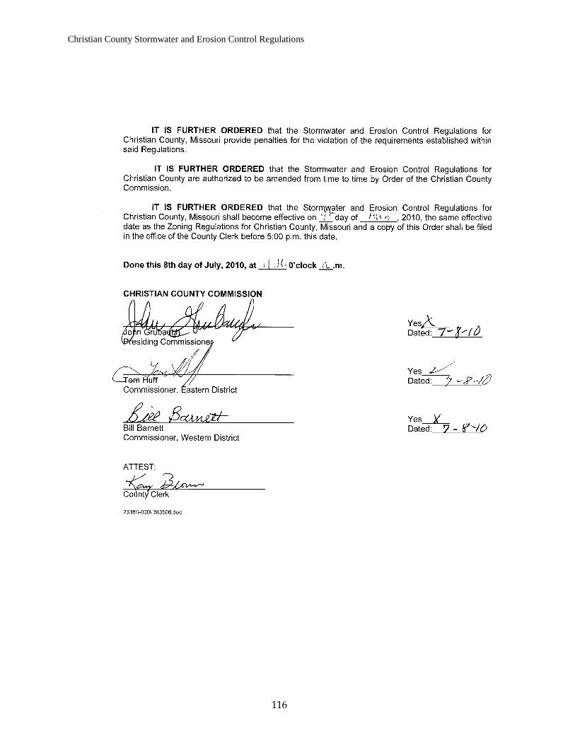
Christian County Stormwater and Erosion Control Regulations
116


![Bureau of Watershed Management Regulatory Proposal Chapter 102 [Erosion and Sediment Control] Erosion, Sediment and Stormwater Management February 21,](https://static.fdocuments.us/doc/165x107/5697bfd61a28abf838cae07f/bureau-of-watershed-management-regulatory-proposal-chapter-102-erosion-and.jpg)