Storm Readiness & Transmission System Hardening
34
Storm Readiness & Transmission System Hardening Nebraska Public Power District Scott Walz T&D Construction and Maintenance Manager
Transcript of Storm Readiness & Transmission System Hardening
Storm Readiness & Transmission System
HardeningNebraska Public Power District
Scott Walz T&D Construction and Maintenance Manager
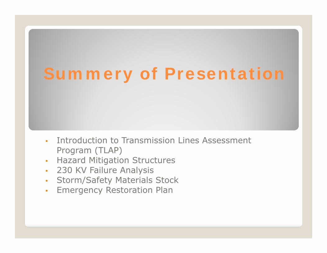
Summery of Presentation
• Introduction to Transmission Lines Assessment Program (TLAP)
• Hazard Mitigation Structures• 230 KV Failure Analysis• Storm/Safety Materials Stock• Emergency Restoration Plan
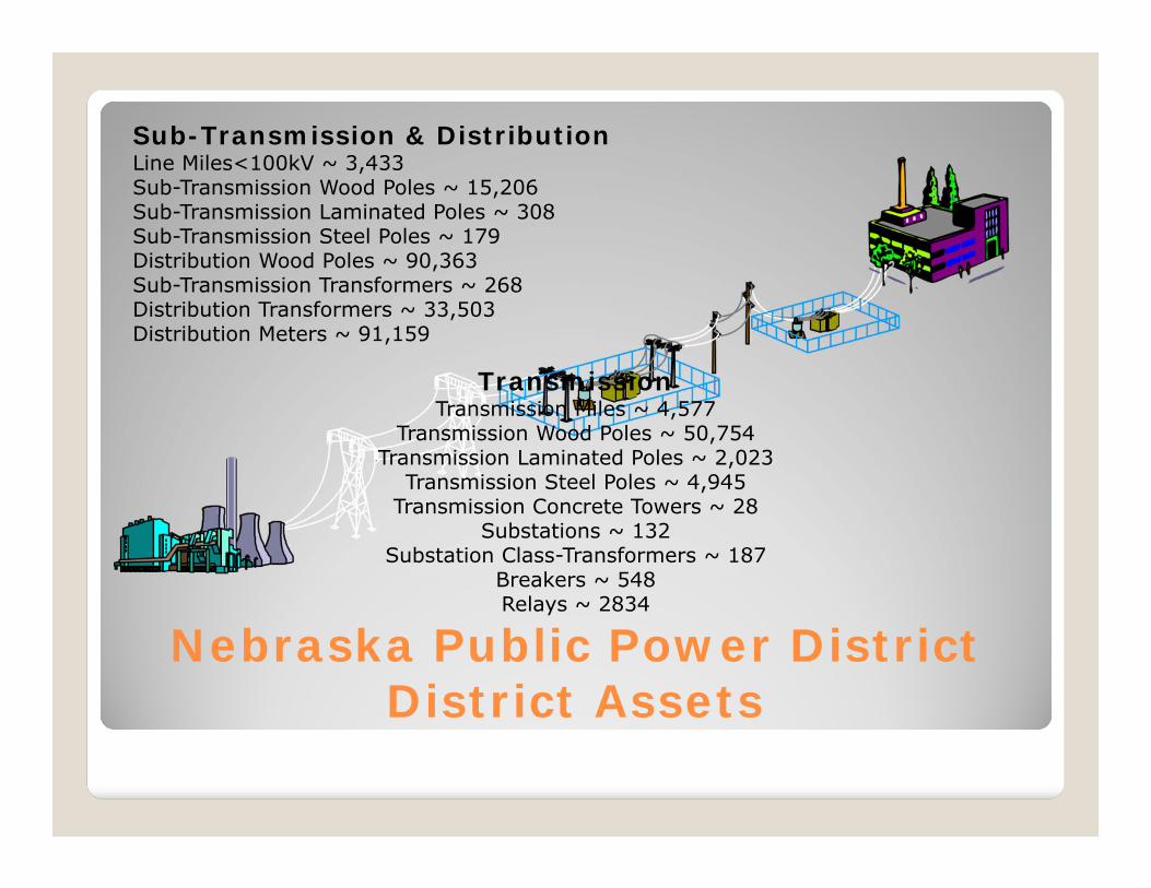
TransmissionTransmission Miles ~ 4,577
Transmission Wood Poles ~ 50,754Transmission Laminated Poles ~ 2,023
Transmission Steel Poles ~ 4,945Transmission Concrete Towers ~ 28
Substations ~ 132Substation Class-Transformers ~ 187
Breakers ~ 548Relays ~ 2834
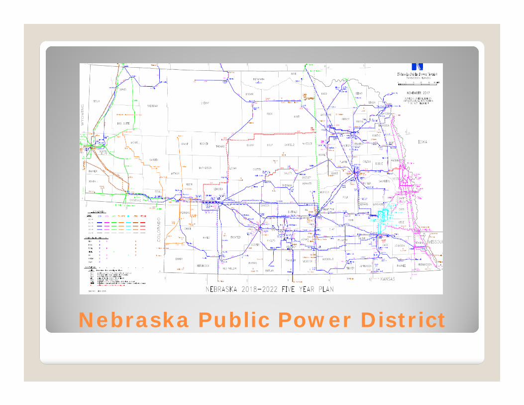
Nebraska Public Power District District Assets
Sub-Transmission & DistributionLine Miles<100kV ~ 3,433Sub-Transmission Wood Poles ~ 15,206Sub-Transmission Laminated Poles ~ 308Sub-Transmission Steel Poles ~ 179Distribution Wood Poles ~ 90,363Sub-Transmission Transformers ~ 268Distribution Transformers ~ 33,503Distribution Meters ~ 91,159
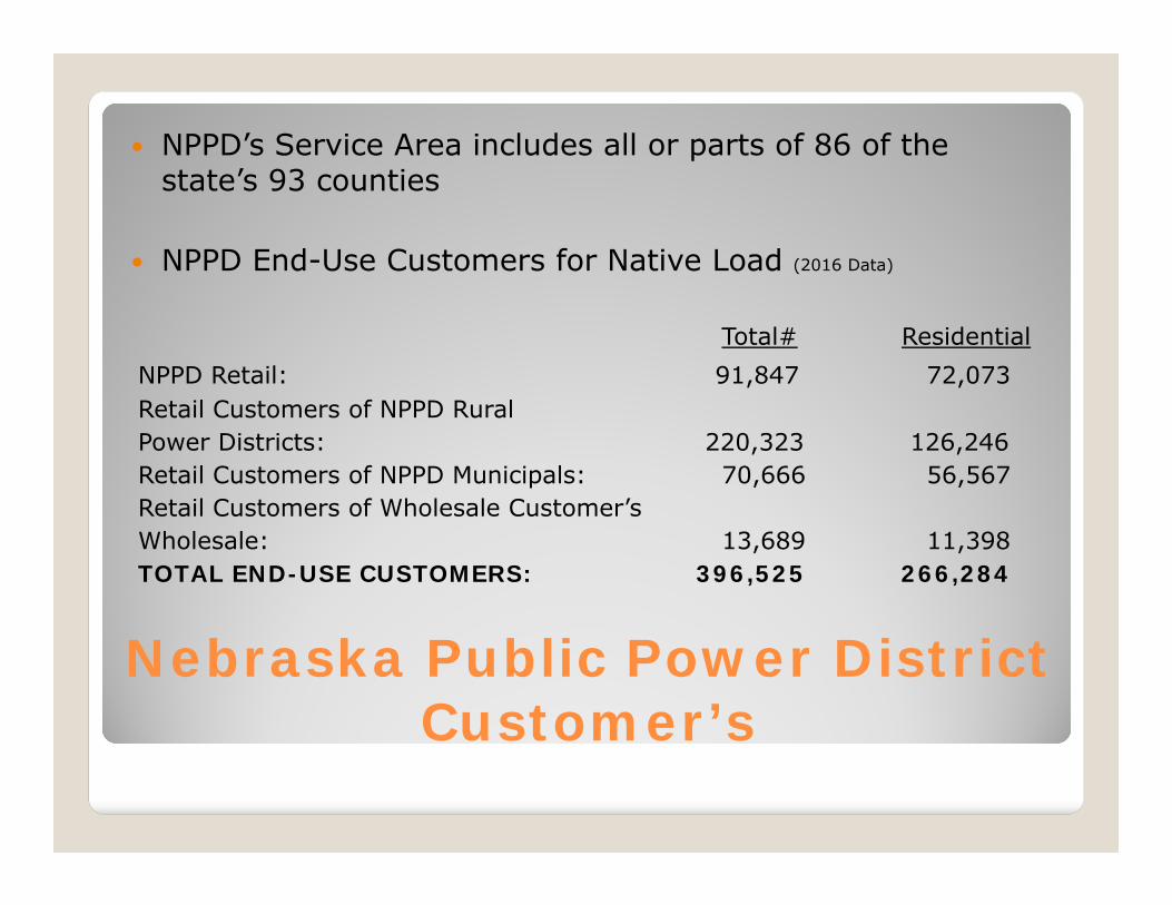
Nebraska Public Power District Customer’s
NPPD’s Service Area includes all or parts of 86 of the state’s 93 counties
NPPD End-Use Customers for Native Load (2016 Data)
Total# Residential
NPPD Retail: 91,847 72,073Retail Customers of NPPD RuralPower Districts: 220,323 126,246Retail Customers of NPPD Municipals: 70,666 56,567Retail Customers of Wholesale Customer’sWholesale: 13,689 11,398TOTAL END-USE CUSTOMERS: 396,525 266,284
Nebraska Public Power District
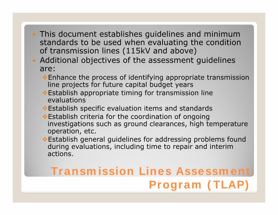
Transmission Lines Assessment Program (TLAP)
This document establishes guidelines and minimum standards to be used when evaluating the condition of transmission lines (115kV and above)
Additional objectives of the assessment guidelines are:Enhance the process of identifying appropriate transmission
line projects for future capital budget yearsEstablish appropriate timing for transmission line
evaluationsEstablish specific evaluation items and standardsEstablish criteria for the coordination of ongoing
investigations such as ground clearances, high temperature operation, etc.Establish general guidelines for addressing problems found
during evaluations, including time to repair and interim actions.
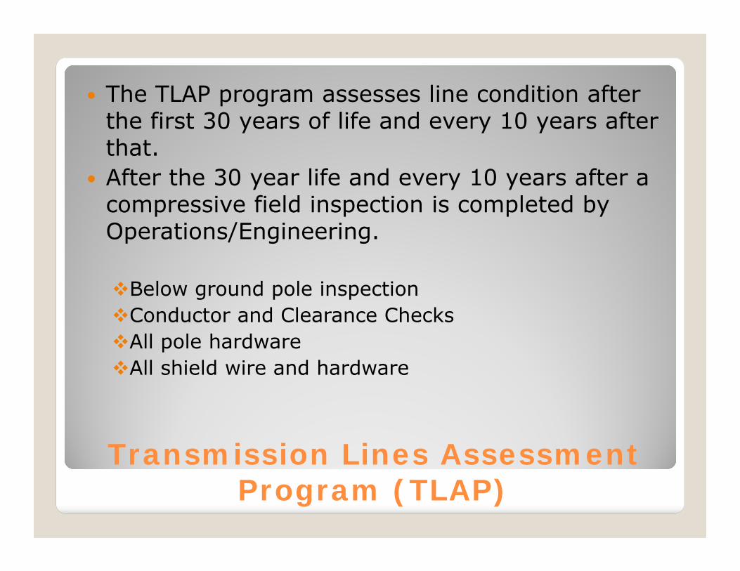
Transmission Lines Assessment Program (TLAP)
The TLAP program assesses line condition after the first 30 years of life and every 10 years after that.
After the 30 year life and every 10 years after a compressive field inspection is completed by Operations/Engineering.
Below ground pole inspectionConductor and Clearance ChecksAll pole hardwareAll shield wire and hardware
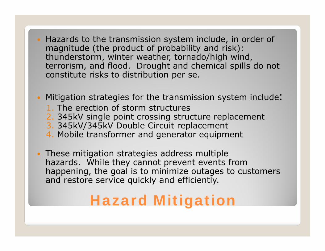
Hazard Mitigation
Hazards to the transmission system include, in order of magnitude (the product of probability and risk): thunderstorm, winter weather, tornado/high wind, terrorism, and flood. Drought and chemical spills do not constitute risks to distribution per se.
Mitigation strategies for the transmission system include:1. The erection of storm structures2. 345kV single point crossing structure replacement3. 345kV/345kV Double Circuit replacement4. Mobile transformer and generator equipment
These mitigation strategies address multiple hazards. While they cannot prevent events from happening, the goal is to minimize outages to customers and restore service quickly and efficiently.

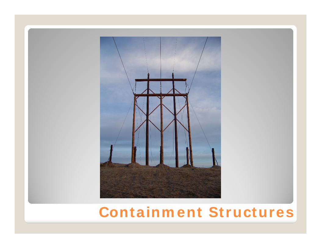
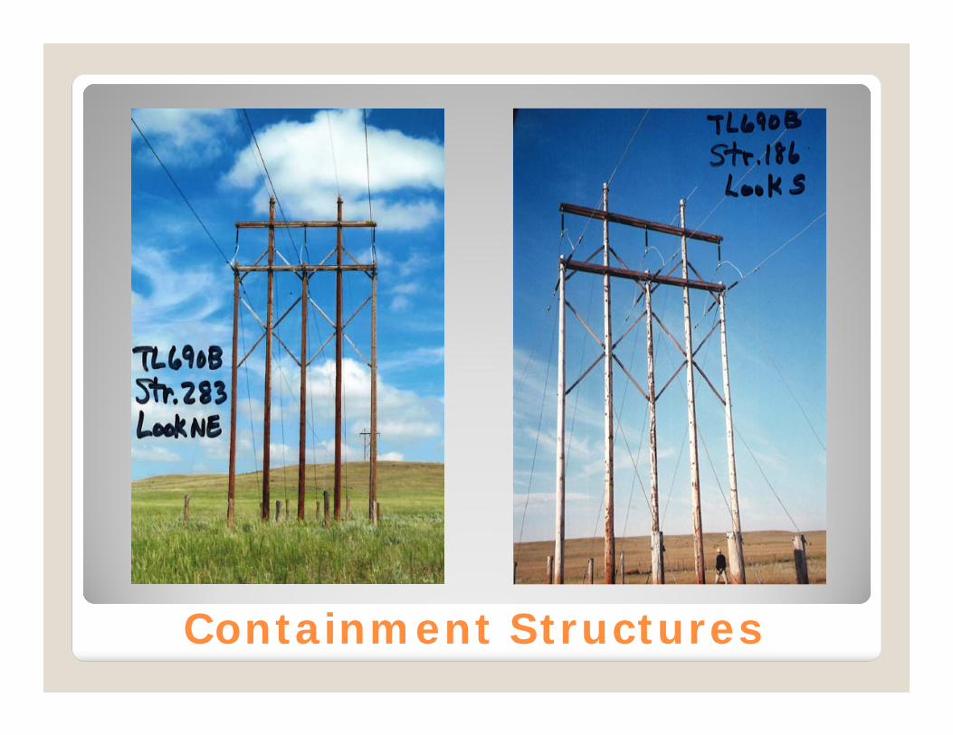
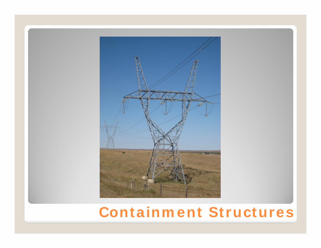
Containment Structures
Two Types of Containment Structures, 5 pole wood and heavy steel DE Towers
Total of 299 5 pole Wood Structures installed since 1998
Total of 20 Steel DE Towers Installed Cost of 5 Pole Wood 60K to 70K Cost of Steel DE Tower 150K to 200K FEMA Grant Reimbursement 60% of
eligible costs.
Containment Structures
Containment Structures
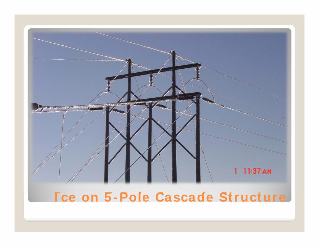
Ice on 5-Pole Cascade Structure
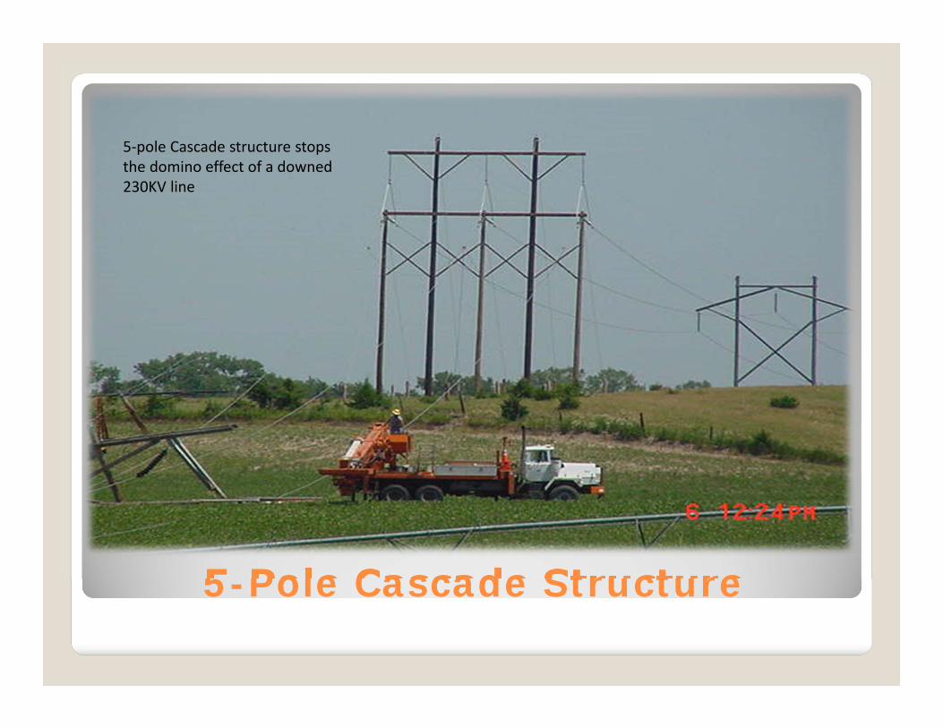
5-Pole Cascade Structure
5-pole Cascade structure stops the domino effect of a downed 230KV line
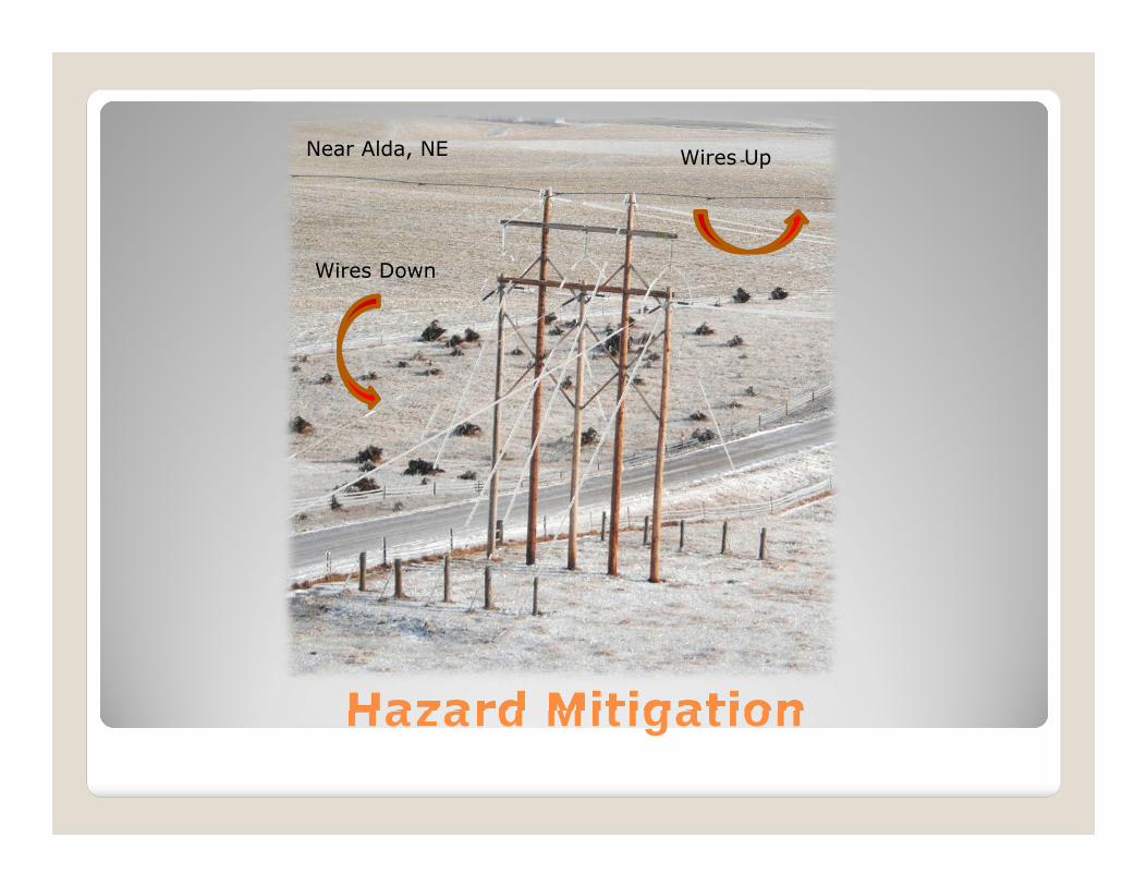
Hazard Mitigation
Near Alda, NE
Wires Down
Wires Up
Containment Structures

May 10, 2011Presented by Mark Shaw and Andy Stewart
230 kV Failure Analysis
Project Overview
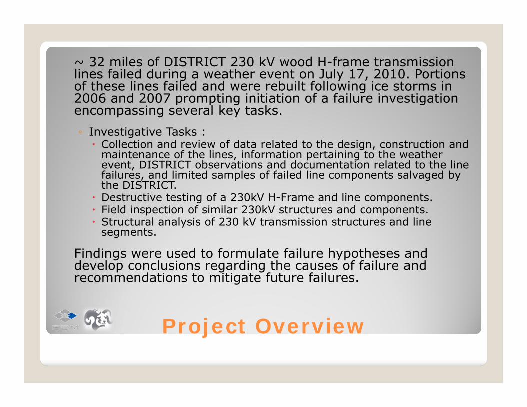
~ 32 miles of DISTRICT 230 kV wood H-frame transmission lines failed during a weather event on July 17, 2010. Portions of these lines failed and were rebuilt following ice storms in 2006 and 2007 prompting initiation of a failure investigation encompassing several key tasks.
◦ Investigative Tasks : Collection and review of data related to the design, construction and
maintenance of the lines, information pertaining to the weather event, DISTRICT observations and documentation related to the line failures, and limited samples of failed line components salvaged by the DISTRICT.
Destructive testing of a 230kV H-Frame and line components. Field inspection of similar 230kV structures and components. Structural analysis of 230 kV transmission structures and line
segments.
Findings were used to formulate failure hypotheses and develop conclusions regarding the causes of failure and recommendations to mitigate future failures.
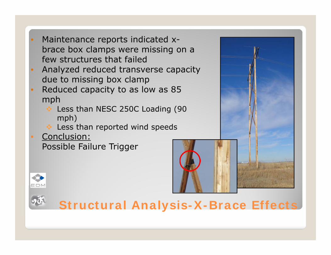
Structural Analysis-X-Brace Effects
• Maintenance reports indicated x-brace box clamps were missing on a few structures that failed
• Analyzed reduced transverse capacity due to missing box clamp
• Reduced capacity to as low as 85 mph Less than NESC 250C Loading (90
mph) Less than reported wind speeds
• Conclusion:Possible Failure Trigger

Recommendations – Existing Lines
Improve longitudinal capacity of structures◦ by the addition of structural reinforcement to the poles◦ the addition of guys/anchors◦ Inter setting new structures with higher longitudinal
strength◦ implement mechanical fuses, if practical fuse can be
developed.
Develop failure investigation procedures and guidelines.
Develop enhanced inspection and QA/QC procedures to ensure all structural and electrical hardware is properly installed.
Recommendations – Existing Lines
Enhance the procurement specifications for laminated poles to be more stringent than the manufacturer’s minimum specifications.
Increase the longitudinal loading design requirements for laminated wood H-frame structures. Evaluate the benefits of installing laminated poles in H-frame structures with strong axis in the longitudinal direction.
Design a small number of tangent structures at regular intervals with increased longitudinal capacity to contain broken wire loads.
Revisit the design of running angle and dead-end structures and investigate the feasibility of developing a load case to account for dynamic loads that can develop during extreme weather events.
Recommendations – New Lines
Shorten the interval between dead-end containment structures and, when practical, design angle and dead-end structures for containment to help minimize the extent of cascades.
Verify the adequacy of X-brace sizing and ensure box-clamps are used where necessary.
Conduct a meteorological study to refine the wind loading design criteria for NPPD’s service territory or for specific areas where new lines are to be built.
Require clipping the shield wires prior to stringing the conductors to avoid excessive in-line structure deflection, especially when stringing T2 on laminated H-frame structures.
Develop requirements for detailed QA/QC inspections immediately after construction of new lines or storm reconstruction, along with a climb and tighten inspection within 2 years following construction or reconstruction on wood pole transmission lines.
Storm/Safety Materials Stock
115kV/230kV Wood Stock material to completely
construct and replace 40 –115kv H-frame structures (approximately 5 miles)
Stock material to completely construct and replace 70 –115kV single pole structures (approximately 5 miles)
Stock material to completely construct and replace 16 230kV H-Frame structures (approximately 2 miles)
345kV Lattice/Mono Pole Stock material to completely
construct nine 345kV H-frame structures as replacements for 345kV H-frame, 230kV H-frame or 230kv K-frame structures or as replacements for three 345kV single circuit steel towers
Raise or maintain standard stock material item quantities to a minimum level sufficient to replace damaged or fallen transmission lines in an emergency as follows:
Stock conductors, shield wires, and line hardware in appropriate quantities to reflect the amount of each type of wire on the transmission system, the criticality of each line, etc.

NPPD Emergency Response Plan
Types of conditions that MAY cause the activation of the Emergency Restoration Team include:◦ Severe weather forecasts◦ A security level of orange or red◦ Other conditions requiring a full time response
Three Levels of Activation◦ Local/Minor System Disturbance (Level 1)◦ Regional/Major System Disturbance (Level 2)◦ Statewide/Catastrophic System Disturbance (Level
3)
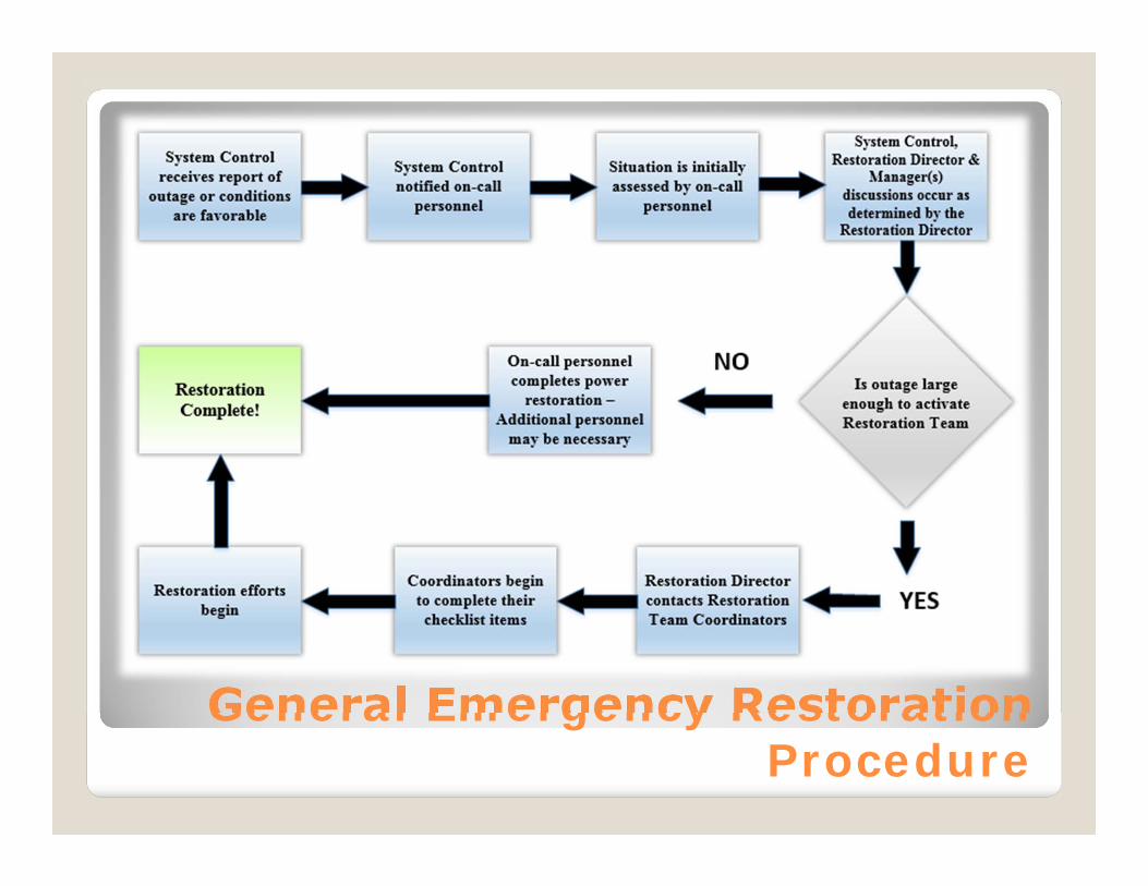
General Emergency Restoration Procedure

Emergency Response Plan
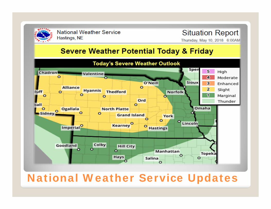
National Weather Service Updates
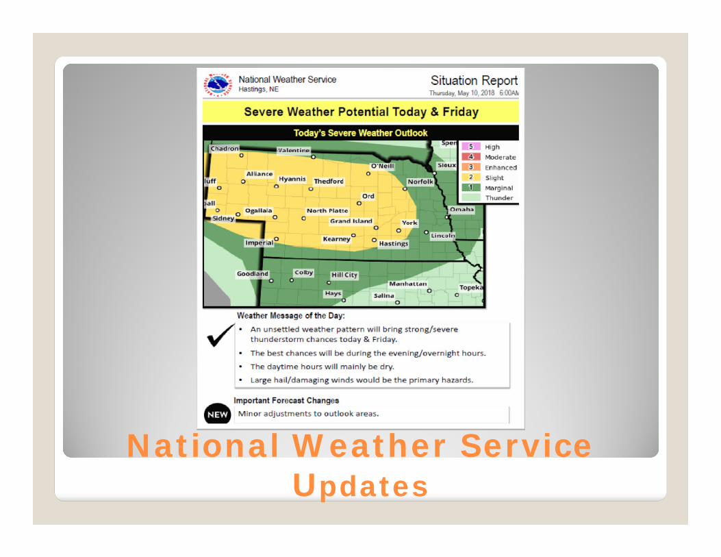
National Weather Service Updates
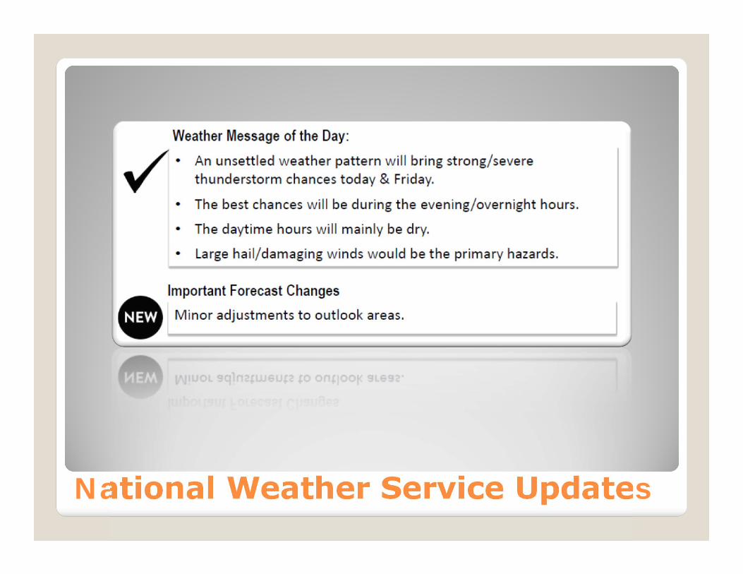
National Weather Service Updates
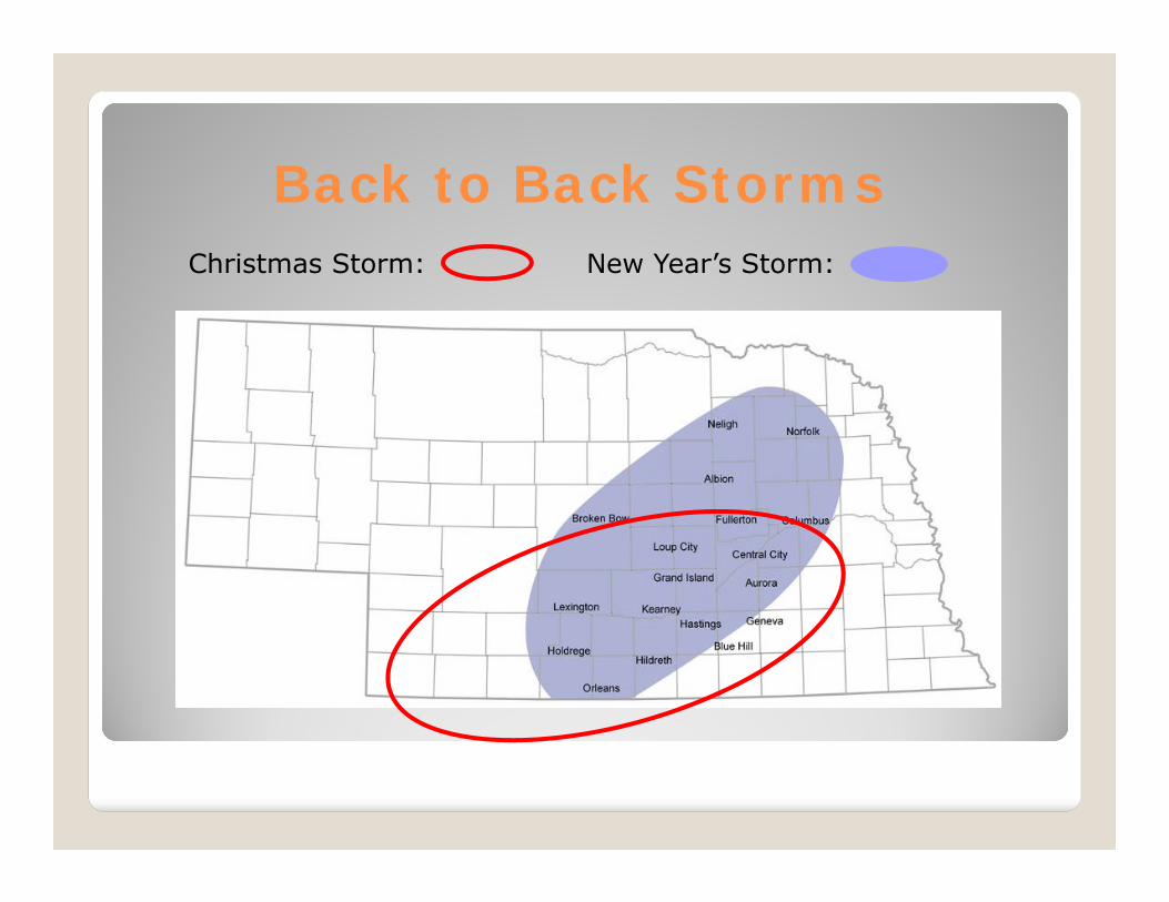
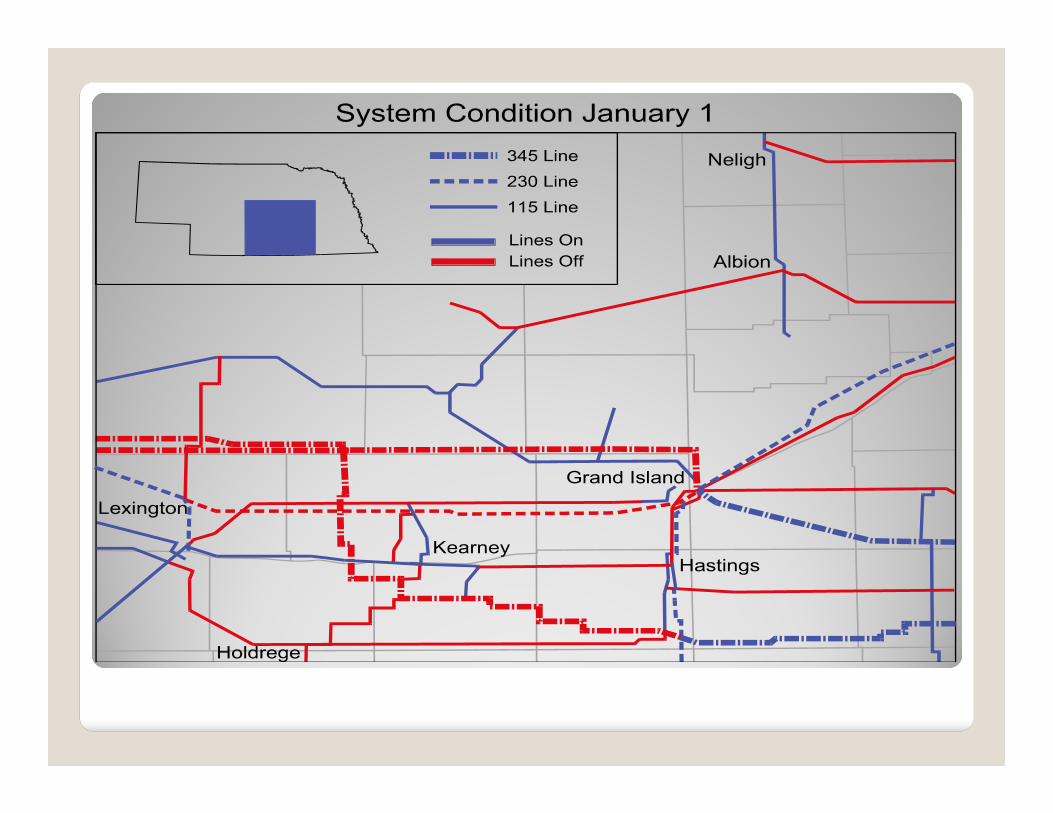
Back to Back StormsChristmas Storm: New Year’s Storm:

Ice on a Guy Wire


Mutual Aid Organizations
• Charter Member of Midwest Mutual Aid Organization• APPA Mutual Assistance Group• Local Nebraska Utility Mutual Aid Organization

Questions?