Storage Shed Plans - Wood Tools 8 x 10 storage... · 2400 x 3000 (8ft x 10ft) Storage Shed Plans...
13
2400 x 3000 (8ft x 10ft) Storage Shed Plans Page 1: Introduction and Contents This detailed shed plan-set is in both Standard and metric dimensions. It is built on skids, meaning that there are no footings or foundations and that the finished shed is able to be moved. The side cladding is board and batten and the roof cladding is corrugated roofing iron over plywood sheathing. Simply go to any page listed below. The plans in the 'Plans' page can be enlarged by clicking on, the step by step instructions also have drawings and any words or terms used in the plan-set are explained in the 'Glossary of Terms'. Stock sizes are nominal sizes(see glossary) Excludes hardware such as nails and other fixing or fastening components. Stock Size/ Material Used For Amount 100x100 (4x4) Natural decay- resistant lumber or treated for in- ground applications Skids 6m (20ft) 150x50 (2x6) Natural decay- resistant lumber or treated for in- ground applications Floor Joists 26m (86ft) 20 (3/4") plywood 2400x1200 (4'x8') sheets Flooring 3 of 100x50(2x4) Framing Lumber Plates; Studs; Cripple Studs; Trimmer Studs; Headers; Noggings; Blockings; Beam supports; Rafters 175m (575ft) 12 (1/2") plywood 2400x1200 (4'x8') sheets Roof Sheathing 4 of 75x50 (2x3) Roof Purlins 20m (60ft) 150x25 (1x6) Natural decay- resistant lumber or treated for exterior use. Barge Board and Fascia Board 14m (46ft) Roof Underlay Vapor and Wind Barrier 10sq M (108sq ft) Corrugated Roofing Iron Roof Cladding 10sq M (108sq ft) Ridge Capping Covers the apex of the roof 6.3m (21ft) Barge Flashing Covers the gable ends of the roof 6.5m (22ft) Cladding Underlay Vapor and Wind Barrier 28sq m (300sq ft) 200x25 (1x8) Natural decay- resistant lumber or treated for exterior use Vertical Cladding Boards 130m (426ft) 75x25 (1x3) Natural decay-resistant lumber or treated for exterior use Vertical Cladding Battens 150m (492ft)
Transcript of Storage Shed Plans - Wood Tools 8 x 10 storage... · 2400 x 3000 (8ft x 10ft) Storage Shed Plans...
2400 x 3000 (8ft x 10ft)
Storage Shed Plans
Page 1: Introduction and Contents This detailed shed plan-set is in both Standard and metric dimensions. It is built on skids, meaning that there are no footings or foundations and that the finished shed is able to be moved. The side cladding is board and batten and the roof cladding is corrugated roofing iron over plywood sheathing. Simply go to any page listed below. The plans in the 'Plans' page can be enlarged by clicking on, the step by step instructions also have drawings and any words or terms used in the plan-set are explained in the 'Glossary of Terms'.
Stock sizes are nominal sizes(see glossary) Excludes hardware such as nails and other fixing or fastening components.
Stock Size/ Material Used For Amount 100x100 (4x4) Natural decay-resistant lumber or treated for in-ground applications
Skids 6m (20ft)
150x50 (2x6) Natural decay-resistant lumber or treated for in-ground applications
Floor Joists 26m (86ft)
20 (3/4") plywood 2400x1200 (4'x8') sheets Flooring 3 of
100x50(2x4) Framing Lumber Plates; Studs; Cripple Studs; Trimmer Studs; Headers; Noggings; Blockings; Beam supports; Rafters
175m (575ft)
12 (1/2") plywood 2400x1200 (4'x8') sheets Roof Sheathing 4 of
75x50 (2x3) Roof Purlins 20m (60ft) 150x25 (1x6) Natural decay-resistant lumber or treated for exterior use.
Barge Board and Fascia Board 14m (46ft)
Roof Underlay Vapor and Wind Barrier 10sq M (108sq ft)
Corrugated Roofing Iron Roof Cladding 10sq M (108sq ft)
Ridge Capping Covers the apex of the roof 6.3m (21ft) Barge Flashing Covers the gable ends of the roof 6.5m (22ft)
Cladding Underlay Vapor and Wind Barrier 28sq m (300sq ft)
200x25 (1x8) Natural decay-resistant lumber or treated for exterior use
Vertical Cladding Boards 130m (426ft)
75x25 (1x3) Natural decay-resistant lumber or treated for exterior use Vertical Cladding Battens 150m (492ft)
760 (30") Pre-Hung Door See NOTE 1 below 1 of 1200 (4ft) wide x 600 (2ft) high complete window See NOTE 2 below 1 of
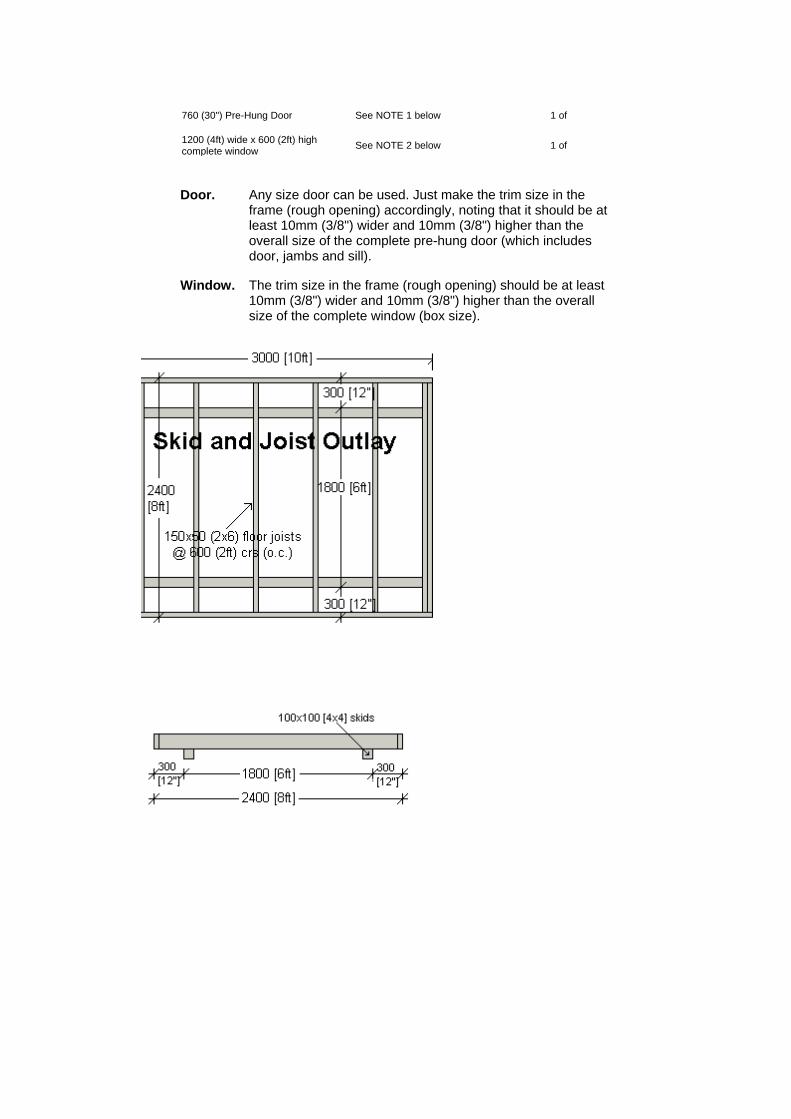
Door. Any size door can be used. Just make the trim size in the frame (rough opening) accordingly, noting that it should be at least 10mm (3/8") wider and 10mm (3/8") higher than the overall size of the complete pre-hung door (which includes door, jambs and sill).
Window.
The trim size in the frame (rough opening) should be at least 10mm (3/8") wider and 10mm (3/8") higher than the overall size of the complete window (box size).
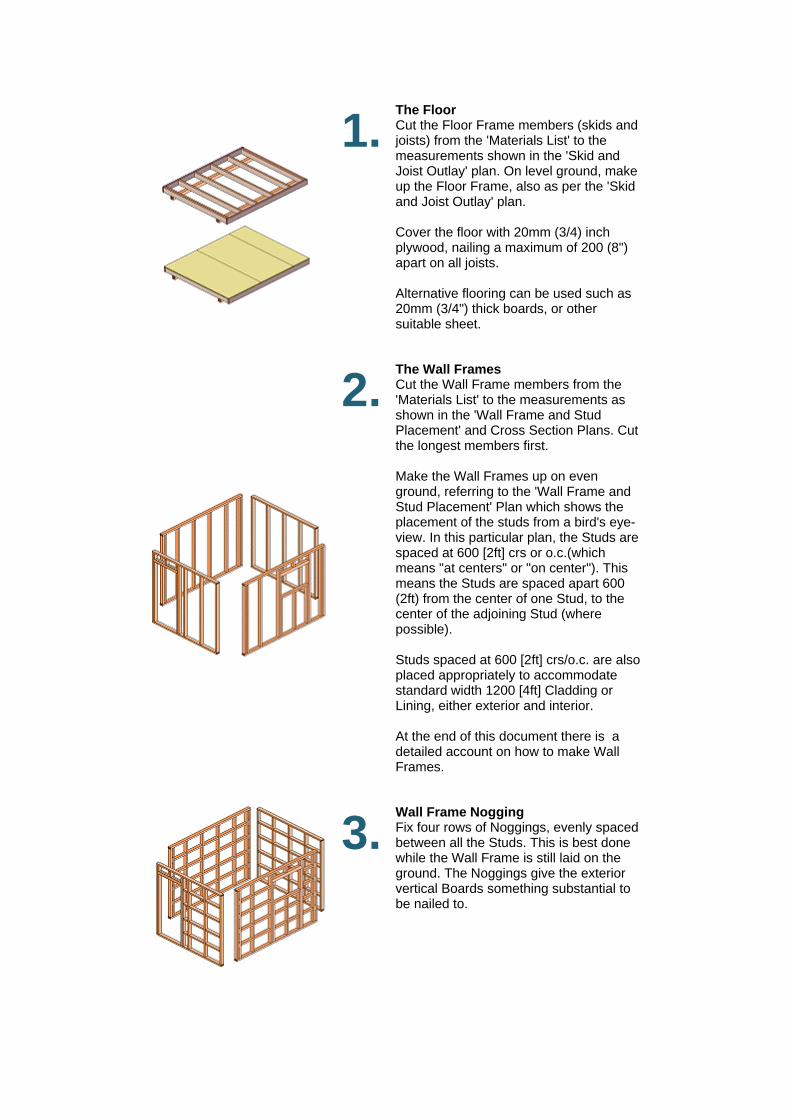
1. The Floor Cut the Floor Frame members (skids and joists) from the 'Materials List' to the measurements shown in the 'Skid and Joist Outlay' plan. On level ground, make up the Floor Frame, also as per the 'Skid and Joist Outlay' plan. Cover the floor with 20mm (3/4) inch plywood, nailing a maximum of 200 (8") apart on all joists. Alternative flooring can be used such as 20mm (3/4") thick boards, or other suitable sheet.
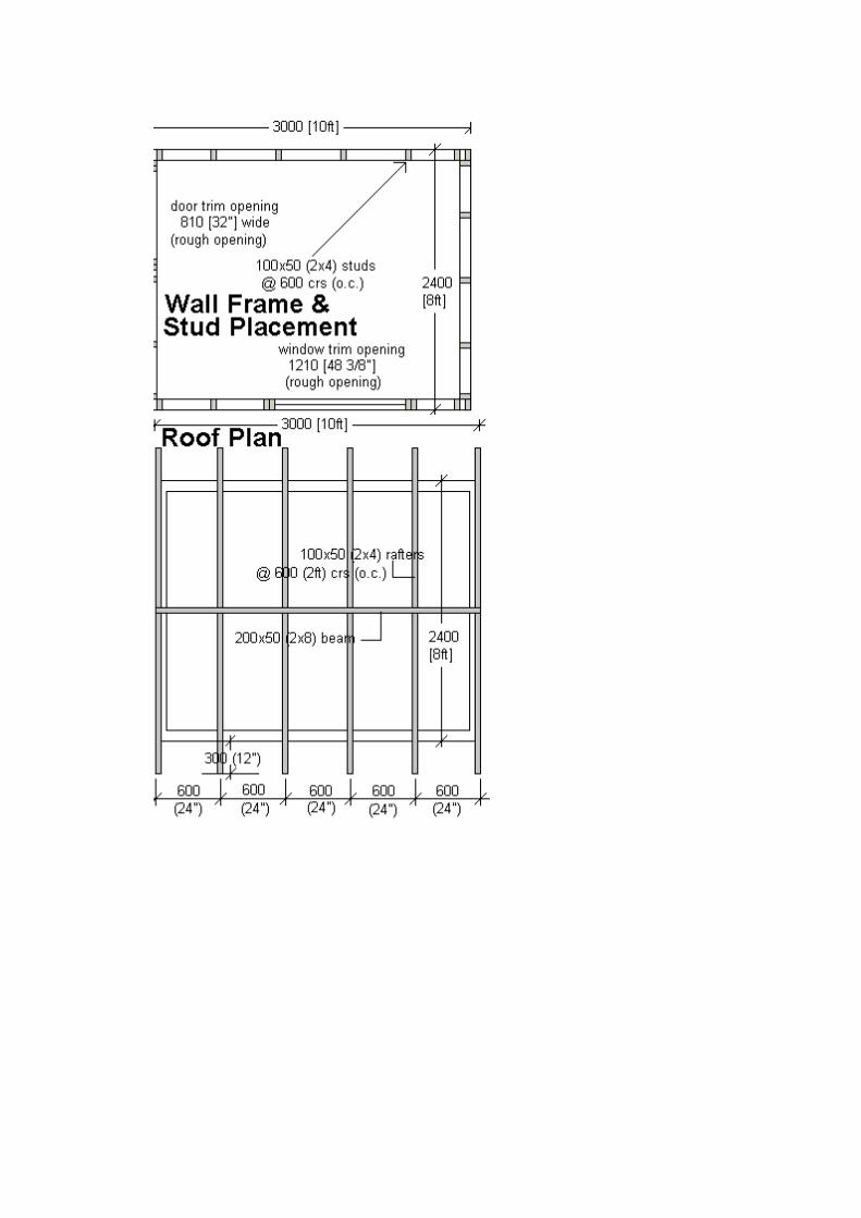
2. The Wall Frames Cut the Wall Frame members from the 'Materials List' to the measurements as shown in the 'Wall Frame and Stud Placement' and Cross Section Plans. Cut the longest members first. Make the Wall Frames up on even ground, referring to the 'Wall Frame and Stud Placement' Plan which shows the placement of the studs from a bird's eye-view. In this particular plan, the Studs are spaced at 600 [2ft] crs or o.c.(which means "at centers" or "on center"). This means the Studs are spaced apart 600 (2ft) from the center of one Stud, to the center of the adjoining Stud (where possible). Studs spaced at 600 [2ft] crs/o.c. are also placed appropriately to accommodate standard width 1200 [4ft] Cladding or Lining, either exterior and interior. At the end of this document there is a detailed account on how to make Wall Frames.
3. Wall Frame Nogging Fix four rows of Noggings, evenly spaced between all the Studs. This is best done while the Wall Frame is still laid on the ground. The Noggings give the exterior vertical Boards something substantial to be nailed to.
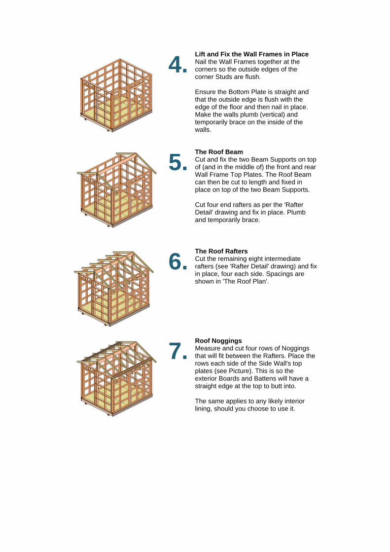
4. Lift and Fix the Wall Frames in Place Nail the Wall Frames together at the corners so the outside edges of the corner Studs are flush. Ensure the Bottom Plate is straight and that the outside edge is flush with the edge of the floor and then nail in place. Make the walls plumb (vertical) and temporarily brace on the inside of the walls.
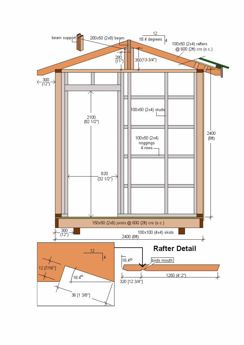
5. The Roof Beam Cut and fix the two Beam Supports on top of (and in the middle of) the front and rear Wall Frame Top Plates. The Roof Beam can then be cut to length and fixed in place on top of the two Beam Supports. Cut four end rafters as per the 'Rafter Detail' drawing and fix in place. Plumb and temporarily brace.
6. The Roof Rafters Cut the remaining eight intermediate rafters (see 'Rafter Detail' drawing) and fix in place, four each side. Spacings are shown in 'The Roof Plan'.
7. Roof Noggings Measure and cut four rows of Noggings that will fit between the Rafters. Place the rows each side of the Side Wall's top plates (see Picture). This is so the exterior Boards and Battens will have a straight edge at the top to butt into. The same applies to any likely interior lining, should you choose to use it.
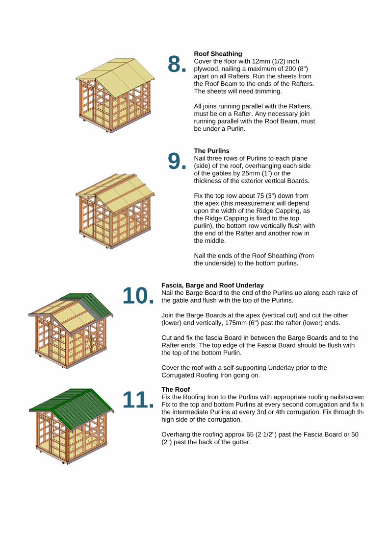
8. Roof Sheathing Cover the floor with 12mm (1/2) inch plywood, nailing a maximum of 200 (8") apart on all Rafters. Run the sheets from the Roof Beam to the ends of the Rafters. The sheets will need trimming. All joins running parallel with the Rafters, must be on a Rafter. Any necessary join running parallel with the Roof Beam, must be under a Purlin.
9. The Purlins Nail three rows of Purlins to each plane (side) of the roof, overhanging each side of the gables by 25mm (1") or the thickness of the exterior vertical Boards. Fix the top row about 75 (3") down from the apex (this measurement will depend upon the width of the Ridge Capping, as the Ridge Capping is fixed to the top purlin), the bottom row vertically flush with the end of the Rafter and another row in the middle. Nail the ends of the Roof Sheathing (from the underside) to the bottom purlins.
10. Fascia, Barge and Roof Underlay Nail the Barge Board to the end of the Purlins up along each rake of the gable and flush with the top of the Purlins. Join the Barge Boards at the apex (vertical cut) and cut the other (lower) end vertically, 175mm (6") past the rafter (lower) ends. Cut and fix the fascia Board in between the Barge Boards and to the Rafter ends. The top edge of the Fascia Board should be flush with the top of the bottom Purlin. Cover the roof with a self-supporting Underlay prior to the Corrugated Roofing Iron going on.
11. The Roof Fix the Roofing Iron to the Purlins with appropriate roofing nails/screwsFix to the top and bottom Purlins at every second corrugation and fix tothe intermediate Purlins at every 3rd or 4th corrugation. Fix through thehigh side of the corrugation. Overhang the roofing approx 65 (2 1/2") past the Fascia Board or 50 (2") past the back of the gutter.
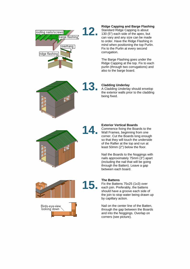
12. Ridge Capping and Barge Flashing Standard Ridge Capping is about 130 (5") each side of the apex, but can vary and any size can be made to order. Have the Ridge Flashing in mind when positioning the top Purlin. Fix to the Purlin at every second corrugation. The Barge Flashing goes under the Ridge Capping at the top. Fix to each purlin (through two corrugations) and also to the barge board.
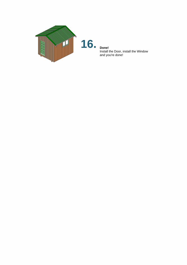
13. Cladding Underlay A Cladding Underlay should envelop the exterior walls prior to the cladding being fixed.
14. Exterior Vertical Boards Commence fixing the Boards to the Wall Frames, beginning from one corner. Cut the Boards long enough so that they will touch the underside of the Rafter at the top and run at least 50mm (2") below the floor. Nail the Boards to the Noggings with nails approximately 75mm (3") apart (including the nail that will be going through the Batten). Leave a gap between each board.
15. The Battens Fix the Battens 75x25 (1x3) over each join. Preferably, the battens should have a groove each side of the join to stop water being drawn up by capillary action. Nail on the center line of the Batten, through the gap between the Boards and into the Noggings. Overlap on corners (see picture).
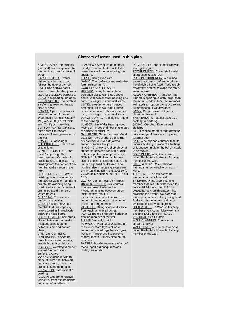
16.
Done! Install the Door, install the Window and you're done!
Glossary of terms used in this plan
ACTUAL SIZE: The finished (dressed) size as opposed to the nominal size of a piece of wood. BARGE BOARD: Exterior visible flat trim board that follows the rake of the roof. BATTENS: Narrow board used to cover cladding joins or used for decorative purposes. BEAM: A supporting member. BIRD'S MOUTH: The notch in a rafter that rests on the top plate of a wall. BOARD: A piece of sawn, or dressed timber of greater width than thickness. Usually 19 (3/4") to 38 (1 1/2") thick and 75 (3") or more wide. BOTTOM PLATE: Wall plate, sole plate; The bottom horizontal framing member of the wall. BRACE: To make rigid. BUILDING LINE: The outline of a building. CENTERS: Crs; O.C; Term used for spacing; The measurement of spacing for studs, rafters, and joists in a building from the center of one member to the center of the next. CLADDING UNDERLAY: A building paper that envelops the exterior walls or roof frame prior to the cladding being fixed. Reduces air movement and helps avoid the risk of water ingress. CLADDING: The exterior surface of a building. CLEAT: A short horizontal member that ties opposing rafters together immediately below the ridge board. CRIPPLE STUD: Short studs placed between the header / lintel and a top plate or between a sill and bottom plate. CRS: See CENTERS. DIMENSIONS: Any of the three linear measurements, length, breadth and depth. DRESSED: Relating to timber; Planed; Smooth; even surface; gauged. DWANG: Nogging; A short piece of timber set between two studs, joists, rafters or purlins to keep them rigid. ELEVATION: Side view of a building. FASCIA: Exterior horizontal visible flat front trim board that caps the rafter tail ends.
FLASHING: Any piece of material, usually metal or plastic, installed to prevent water from penetrating the structure. FLUSH: Being even with. GABLE: The roof ends and walls that form an inverted "V". GAUGED: See DRESSED. HEADER: Lintel; A beam placed perpendicular to wall studs above doors, windows or other openings, to carry the weight of structural loads. LINTEL: Header; A beam placed perpendicular to wall studs above doors, windows or other openings to carry the weight of structural loads. LONGITUDINAL: Running the length of the building. LUMBER: Any of the framing wood. MEMBER: Piece of timber that is part of a frame or structure. NAIL PLATE: Gang nail plate; Metal plate with rows of sharp points that are hammered into butt-jointed timber to secure the join. NOGGING: Dwang; A short piece of timber set between two studs, joists, rafters or purlins to keep them rigid. NOMINAL SIZE: The rough-sawn size of a piece of lumber. Before the lumber is planed or dressed. The nominal size is usually greater than the actual dimension. e.g. 100x50 (2 x 4) actually equals 90x45 (1 1/2" x 3 1/2"). O.C.: On center; (See CENTERS) ON CENTER (O.C.) Crs, centers. The term used to define the measured spacing between studs, joists, rafters, etc. O.C. measurements are taken from the center of one member to the center of the adjoining member. PARALLEL: Being of equal distance from each other at all points. PLATE: The top or bottom horizontal framing member of the wall PLUMB: Vertical; Upright. PLYWOOD: A piece of wood made of three or more layers of wood veneer laminated together with glue. PURLIN: Timber used to support roofing sheets. Usually fixed on top of rafters. RAFTER: Parallel members of a roof that support battens/purlins and roofing materials.
RECTANGLE: Four-sided figure with four right angles. ROOFING IRON: Corrugated metal sheet used to clad roof. ROOFING UNDERLAY: A building paper that covers roof frame prior to the cladding being fixed. Reduces air movement and helps avoid the risk of water ingress. ROUGH OPENING: Trim size; The framed-in opening, slightly larger than the actual window/door, that replaces wall studs to support the structure and accommodate a window/door. SAWN: Rough sawn; Not gauged, planed or dressed. SHEATHING: A material used as a backing to cladding. SIDING: Cladding; Exterior wall cladding. SILL: Framing member that forms the bottom edge of the window opening or external door. SKID: A solid piece of timber that fits under a building in place of a footings or foundation making the building able to be moved. SOLE PLATE: wall plate, bottom plate; The bottom horizontal framing member of the wall. STUD: A 100x50 (2x4) vertical framing member used to construct walls. TOP PLATE: The top horizontal framing member of the wall. TRIMMER: Under stud; Framing member that is cut to fit between the bottom PLATE and the HEADER. UNDERLAY: A building paper that envelops the exterior walls or roof frame prior to the cladding being fixed. Reduces air movement and helps avoid the risk of water ingress. UNDER STUD: TRIMMER; Framing member that is cut to fit between the bottom PLATE and the HEADER. VERTICAL: See PLUMB. WALL CLADDING: The exterior surface of a wall. WALL PLATE: wall plate, sole plate plate; The bottom horizontal framing member of the wall.
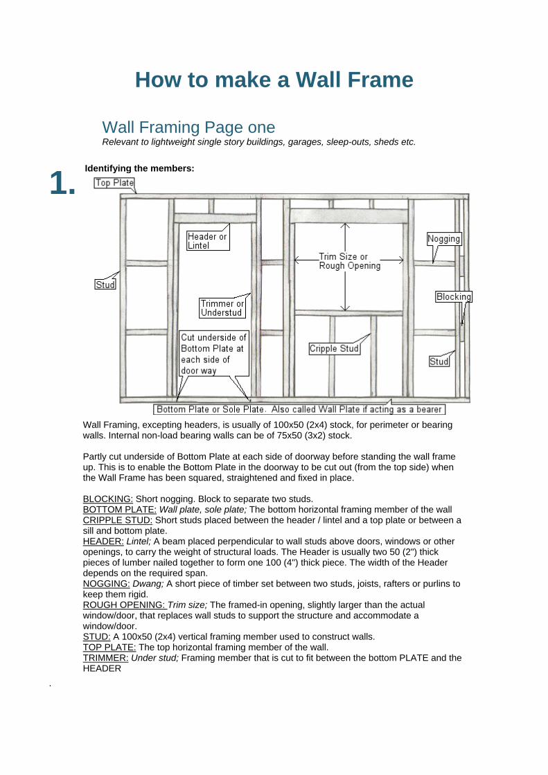
How to make a Wall Frame Wall Framing Page one Relevant to lightweight single story buildings, garages, sleep-outs, sheds etc.
1.
Identifying the members:
Wall Framing, excepting headers, is usually of 100x50 (2x4) stock, for perimeter or bearing walls. Internal non-load bearing walls can be of 75x50 (3x2) stock. Partly cut underside of Bottom Plate at each side of doorway before standing the wall frame up. This is to enable the Bottom Plate in the doorway to be cut out (from the top side) when the Wall Frame has been squared, straightened and fixed in place. BLOCKING: Short nogging. Block to separate two studs. BOTTOM PLATE: Wall plate, sole plate; The bottom horizontal framing member of the wall CRIPPLE STUD: Short studs placed between the header / lintel and a top plate or between a sill and bottom plate. HEADER: Lintel; A beam placed perpendicular to wall studs above doors, windows or other openings, to carry the weight of structural loads. The Header is usually two 50 (2") thick pieces of lumber nailed together to form one 100 (4") thick piece. The width of the Header depends on the required span. NOGGING: Dwang; A short piece of timber set between two studs, joists, rafters or purlins to keep them rigid. ROUGH OPENING: Trim size; The framed-in opening, slightly larger than the actual window/door, that replaces wall studs to support the structure and accommodate a window/door. STUD: A 100x50 (2x4) vertical framing member used to construct walls. TOP PLATE: The top horizontal framing member of the wall. TRIMMER: Under stud; Framing member that is cut to fit between the bottom PLATE and the HEADER
.
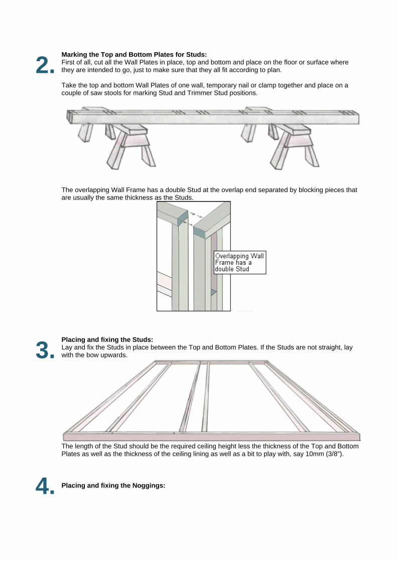
2. Marking the Top and Bottom Plates for Studs: First of all, cut all the Wall Plates in place, top and bottom and place on the floor or surface where they are intended to go, just to make sure that they all fit according to plan. Take the top and bottom Wall Plates of one wall, temporary nail or clamp together and place on a couple of saw stools for marking Stud and Trimmer Stud positions.
The overlapping Wall Frame has a double Stud at the overlap end separated by blocking pieces that are usually the same thickness as the Studs.
3. Placing and fixing the Studs: Lay and fix the Studs in place between the Top and Bottom Plates. If the Studs are not straight, lay with the bow upwards.
The length of the Stud should be the required ceiling height less the thickness of the Top and Bottom Plates as well as the thickness of the ceiling lining as well as a bit to play with, say 10mm (3/8").
4. Placing and fixing the Noggings:
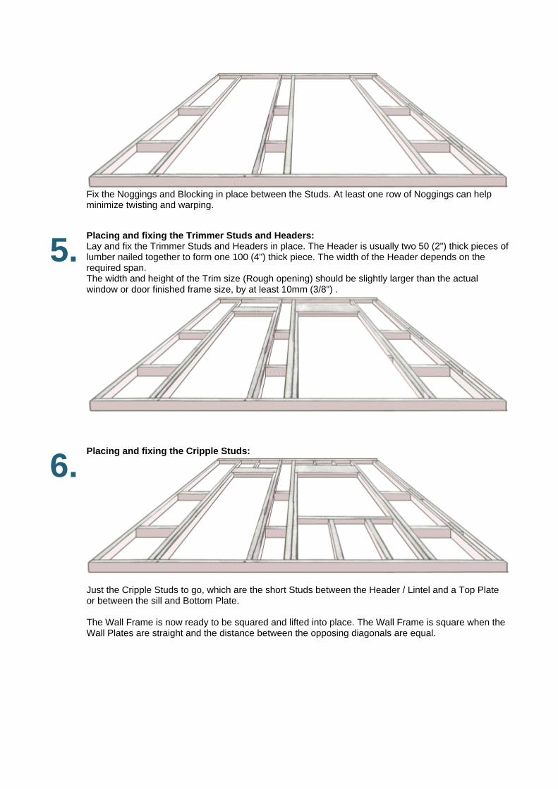
Fix the Noggings and Blocking in place between the Studs. At least one row of Noggings can help minimize twisting and warping.
5. Placing and fixing the Trimmer Studs and Headers: Lay and fix the Trimmer Studs and Headers in place. The Header is usually two 50 (2") thick pieces of lumber nailed together to form one 100 (4") thick piece. The width of the Header depends on the required span. The width and height of the Trim size (Rough opening) should be slightly larger than the actual window or door finished frame size, by at least 10mm (3/8") .
6. Placing and fixing the Cripple Studs:
Just the Cripple Studs to go, which are the short Studs between the Header / Lintel and a Top Plate or between the sill and Bottom Plate. The Wall Frame is now ready to be squared and lifted into place. The Wall Frame is square when the Wall Plates are straight and the distance between the opposing diagonals are equal.