storage Reference Architecture - Cisco · The Storage Reference Architecture from Cisco, Hitachi...
47
Storage Reference Architecture from Cisco, Hitachi and VMware Reference Architecture By Sean McKeown, Cisco Shawn McDonald, Hitachi Data Systems Wen Yu, VMware June 7, 2011
Transcript of storage Reference Architecture - Cisco · The Storage Reference Architecture from Cisco, Hitachi...

Storage Reference Architecture from Cisco, Hitachi and VMware
Reference Architecture
By Sean McKeown, Cisco
Shawn McDonald, Hitachi Data Systems
Wen Yu, VMware
June 7, 2011

Hitachi Data Systems2
AUDIENCE
This document is intended for field System Engineer, Partner Engineers, Sales Engineers and Customers.

Hitachi Data Systems3
TABLE OF CONTENTS
ADVANTAGES 6 Simplified Set-Up and Management 6 More Efficient Hardware Utilization 6 Cost-Effective Operation 6 High Performance 6 Resilience 6 Flexibility 6 SYSTEM OVERVIEW 7 Cisco Unified Compute System (UCS) 8 Blade Server 8 Fabric Interconnect 9 Cisco Nexus 5000 Series Switch 9 Cisco MDS 9148 Multilayer Fabric Switch 10 Hitachi Adaptable Modular Storage 2500 10 VMware vSphere 11 Cisco Nexus 1000v Series Switches 11 MANAGEMENT 12 Cisco UCS Manager 12 Hitachi Storage Navigator Modular 2 12 Cisco Fabric Manager 13 VMware vCenter Server 13 REFERENCE ARCHITECTURE DESIGN AND CONFIGURATION 14 Connecting Devices 15 Configuring Fabric Interconnects 17 Cisco UCS Management Setup and Pool Definitions 19 Hitachi Adaptable Modular Storage 2500 Setup 19 Installation Requirements 19 Configuration 20 Initial Setup 20 Setup Management Ports 21 Host Port Setup 22 Setup Spare Drives 23 Creating RAID Groups and LUNs 24 Creating RAID Groups 25 Creating Logical Units 25 Creating Host Groups 26 LUN provisioning 29 SAN Provisioning 30 VMware vSphere Installation 31 Installing and Configuring Cisco Nexus 1000v and 1010 32 Cisco UCS Pass Through Switching Configuration 32 Requirements 32 Recommended 32
Hitachi Data Systems4
Installation Steps 33 USE CASES 35 Private Cloud Application Server Farm 35 Application Development Server Farm 36 Virtual Desktop Infrastructure 36 VALIDATION RESULTS 38 High Availability Test Results 38 VAAI and Hitachi Adaptable Modular Storage 2500 Validation Results 38 Increased VM Density 38 Dynamic Operations 39 Saved Space Without Increased Performance 42 SUMMARY 43 REFERENCES 44 Hitachi Data Systems 44 Cisco Systems 44 VMware 45 PRODUCT CONFIGURATIONS 46 Hitachi Adaptable Modular Storage 2500 config 46 RAID Configuration 46 LUN configuration 47
Storage Reference Architecture from Cisco, Hitachi and VMware
Reference Architecture
The Storage Reference Architecture from Cisco, Hitachi and VMware offers a blueprint for creating a cloud-ready infrastructure integrating computing, networking, and storage resources. As a validated reference architecture, the storage Reference Architecture is a safe, flexible, and cost-effective alternative to custom-integrated approaches.
The Storage Reference Architecture speeds application and infrastructure deployment and reduces the risk of introducing new technologies to the data center. Administrators select options that meet current needs, with the flexibility to scale the architecture as business needs change.
This document outlines the Storage Reference Architecture from Cisco, Hitachi and VMware, and discusses design choices and deployment best practices. Use cases are described and results from validation work are presented.
Hitachi Data Systems6
ADVANTAGES
The Storage Reference Architecture incorporates the Hitachi Adaptable Modular Storage 2500, the Cisco® Unified Computing System™ (UCS), and VMware vSphere™ and vCenter™ Server (Figure 1). By joining forces, Cisco, Hitachi, and VMware have created an architecture that offers greater value than their individual products could deliver separately. The advantages of this approach include:
SIMPLIFIED SET-UP AND MANAGEMENT
Combining the active-active symmetric controller architecture of the Adaptable Modular Storage 2500 with the VMware vSphere round-robin multipathing policy dramatically simplifies the setup and management of the virtualized environment. Workloads are automatically balanced across host bus adapters (HBAs), SAN fabrics, and front-end Fibre Channel ports of the storage system. Furthermore, Cisco UCS Manager provides centralized management for multiple server blade chassis and allows for rapid blade provisioning by leveraging the stateless hardware abstraction of its service profiles.
MORE EFFICIENT HARDWARE UTILIZATION
The VMware vStorage API for array integration (VAAI) offloads common operations from the Cisco UCS servers to the Hitachi storage controllers. The controller is purpose-built to handle this type of workload. Offloading common operations frees the host servers for more complex tasks, and avoids unnecessary traffic across the SAN fabric. This creates infrastructure-wide efficiencies.
COST-EFFECTIVE OPERATION
Cisco B200 M2 Blade Servers provide flexibility and choice. Servers include a less dense, value-oriented configuration using smaller DIMMs or a more dense, performance-oriented option with larger DIMMs. Pairing the memory-dense capabilities in the Cisco servers with the storage offloading and active-active load-balanced capabilities of the Adaptable Modular Storage 2500 controllers allows a single Cisco UCS server to support a high-density consolidation of virtual machines. Increasing virtual machine density lowers the cost of each virtual machine.
HIGH PERFORMANCE
Cisco UCS industry-standard x86-architecture servers deliver world-record performance to power virtualized workloads in VMware vSphere environments.
RESILIENCE
The Storage Reference Architecture contains no single point of failure at any level, from the server through the network to the storage. Multiple, redundant SAN data paths are actively used without the need for fine-grained, burdensome SAN management. Both the LAN and SAN fabrics are fully redundant and provide seamless traffic failover should any individual component fail.
FLEXIBILITY
The Cisco UCS blade architecture with stateless service profiles and unified fabric, combined with Hitachi Dynamic Provisioning and advanced VMware virtualization management, provide the flexibility and agility to right-size resources to match workloads and adjust to dynamic business and application requirements.
Hitachi Data Systems7
SYSTEM OVERVIEW
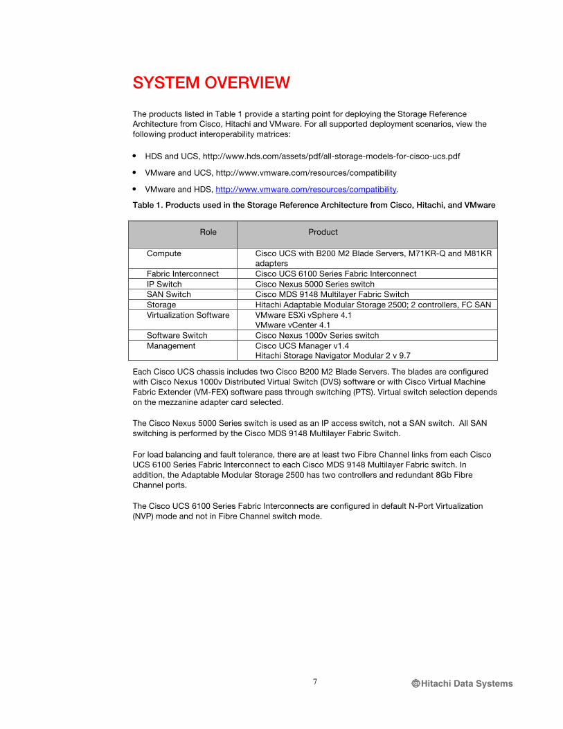
The products listed in Table 1 provide a starting point for deploying the Storage Reference Architecture from Cisco, Hitachi and VMware. For all supported deployment scenarios, view the following product interoperability matrices:
• HDS and UCS, http://www.hds.com/assets/pdf/all-storage-models-for-cisco-ucs.pdf
• VMware and UCS, http://www.vmware.com/resources/compatibility
• VMware and HDS, http://www.vmware.com/resources/compatibility.
Table 1. Products used in the Storage Reference Architecture from Cisco, Hitachi, and VMware
Role Product
Compute Cisco UCS with B200 M2 Blade Servers, M71KR-Q and M81KR adapters
Fabric Interconnect Cisco UCS 6100 Series Fabric Interconnect IP Switch Cisco Nexus 5000 Series switch SAN Switch Cisco MDS 9148 Multilayer Fabric Switch Storage Hitachi Adaptable Modular Storage 2500; 2 controllers, FC SAN Virtualization Software VMware ESXi vSphere 4.1
VMware vCenter 4.1 Software Switch Cisco Nexus 1000v Series switch Management Cisco UCS Manager v1.4
Hitachi Storage Navigator Modular 2 v 9.7
Each Cisco UCS chassis includes two Cisco B200 M2 Blade Servers. The blades are configured with Cisco Nexus 1000v Distributed Virtual Switch (DVS) software or with Cisco Virtual Machine Fabric Extender (VM-FEX) software pass through switching (PTS). Virtual switch selection depends on the mezzanine adapter card selected.
The Cisco Nexus 5000 Series switch is used as an IP access switch, not a SAN switch. All SAN switching is performed by the Cisco MDS 9148 Multilayer Fabric Switch.
For load balancing and fault tolerance, there are at least two Fibre Channel links from each Cisco UCS 6100 Series Fabric Interconnect to each Cisco MDS 9148 Multilayer Fabric switch. In addition, the Adaptable Modular Storage 2500 has two controllers and redundant 8Gb Fibre Channel ports.
The Cisco UCS 6100 Series Fabric Interconnects are configured in default N-Port Virtualization (NVP) mode and not in Fibre Channel switch mode.

Hitachi Data Systems8
Figure 1. The Storage Reference Architecture from Cisco, Hitachi and VMware.
CISCO UNIFIED COMPUTE SYSTEM (UCS)
Cisco UCS is a next-generation data center platform uniting compute, network, storage access, and virtualization in a cohesive system designed to reduce total cost of ownership (TCO) and increase business agility. The system integrates a low-latency, lossless 10 Gigabit Ethernet unified network fabric with enterprise-class x86-architecture servers. Cisco UCS is an integrated, scalable, multi-chassis platform in which all resources participate in a unified management domain.
For Cisco UCS product information visit: http://www.cisco.com/en/US/products/ps10265/index.html
Blade Server
The Cisco UCS B200 M2 Blade Server is a half-width, two-socket blade server with two Intel Xeon 5600 Series processors, up to 192 GB of DDR3 memory, two optional hot-swappable small form factor (SFF) serial attached SCSI (SAS) disk drives, and a single mezzanine connector for up to 20 Gbps of I/O throughput.
!""#$$%%
&'()*+#%
,!-.,+'/01#%%
&2$"'%%
-#3*$%4555%%
&2$"'%
6&,%708/2"%%
9:+#/"'::#"+%%6&,%%
;<0=#%,#/>#/$%%
&2$"'%?@,%%
>A&%%
B3C5DE%%
B3C5DE%%
B3C5DE%%
B3C5DE%%
7&%% 7&%%
>A&%%
7&%% 7&%%
F?G0/#%>,)H#/#%
-#3*$%C555F%%
F?G0/#%>&#:+#/%
I@,%!?,%,+'/01#%

Hitachi Data Systems9
Cisco UCS virtual interface cards were developed to provide acceleration for new operational modes introduced by server virtualization. The cards are highly configurable and self-virtualized adapters that can create up to 128 PCIe endpoints per adapter. These PCIe endpoints are created in the adapter firmware and present fully standards compliant PCIe topology to the host OS or hypervisor.
Each PCIe endpoint created by the virtual interface card can be configured for the following:
• Interface type—FCoE, Ethernet, or Dynamic Ethernet interface device
• Network presence and attributes—MTU, VLAN membership
• Quality of Service (QoS) parameters—802.1p class, ETS attributes, rate limiting, and shaping.
Fabric Interconnect
The Cisco UCS 6100 Series Fabric Interconnects are a core part of the Cisco UCS. They provide network connectivity and management capabilities for the system and offer line-rate, low-latency, lossless 10 Gigabit Ethernet and Fibre Channel over Ethernet (FCoE) functionality, independent of packet size and enabled services.
The Cisco UCS B200 M2 Blade Servers and chassis rely on the Cisco UCS 6100 Series interconnects to provide a management and communication backbone. All connected chassis—and all blades—become part of a single, highly available management domain, with the interconnects providing LAN and SAN connectivity for all blades within the domain.
Cisco UCS 6100 Series Fabric Interconnects support multiple traffic classes from the blade through the interconnect, and can consolidate LAN and SAN traffic onto a single unified fabric. Fibre Channel expansion modules in the interconnect support direct connections from the Cisco UCS to existing native Fibre Channel SANs.
CISCO NEXUS 5000 SERIES SWITCH
The Cisco Nexus 5020 Switch is a 2RU, 10 Gigabit Ethernet/FCoE access layer switch built to provide more than 1.04 terabits per second (Tbps) throughput with very low latency. It has 40 fixed 10 Gigabit Ethernet/FCoE Small Form-Factor Pluggable Plus (SFP+) ports and two expansion module slots that can be configured to support up to twelve additional 10 Gigabit Ethernet/FCoE ports, up to sixteen Fibre Channel switch ports, or a combination of both. The switch has a serial console port and a single out-of-band 10/100/1000-Mbps Ethernet management port. 1+1 redundant hot pluggable power supplies and 4+1 redundant hot pluggable fan modules provide highly reliable power and front-to-back cooling.
Cisco Nexus 5000 Series cut-through switching enables low latency of 3.2 microseconds, which remains constant regardless of packet size and with all data path features turned on—for example, access control lists (ACLs) and QoS.
Other features include: nonblocking line-rate performance, single-stage fabric, congestion management, virtual output queues, lossless Ethernet (Priority Flow Control), hardware-level I/O consolidation, and end-port virtualization. In addition, SFP+ ports offer copper for short runs and fiber for long runs.
The Cisco Nexus 5020 Switch is designed for data center serviceability, with ports and power connections at the rear, closer to server ports to keep cable lengths short. All customer-replaceable units (hot swappable power and cooling modules) are accessible from the front panel.
For Cisco Nexus 5000 Series product information, visit: http://www.cisco.com/en/US/products/ps9670/index.html
Hitachi Data Systems10
CISCO MDS 9148 MULTILAYER FABRIC SWITCH
The Cisco MDS 9148 Multilayer Fabric Switch is designed for deployment in large enterprises. The protocol independent switch offers scalability, high performance, high availability, security, and ease of management. The Cisco MDS 9000 Family includes blade switches through director class switches, with all switches sharing the same operating system (NX-OS) and management interface.
Interfaces supported by the Cisco MDS 9148 Multilayer Fabric Switch include 1-, 2-, 4-, and 8-Gbps Fibre Channel, 10 Gbps FCoE, 1 Gpbs Fibre Channel over IP (FCIP), and 1 Gbps Small Computer System Interface over IP (iSCSI) port speeds.
Other key features include:
• Storage media encryption, for encryption of data at rest
• Cisco Data Mobility Manager, for heterogeneous data migration
• Cisco I/O Accelerator, for increased performance and reduced latency over long-distance SAN extension links
• Cisco SAN Tap network assisted application, for attaching external appliances.
For Cisco MDS 9000 Family product information, visit: http://www.cisco.com/en/US/products/hw/ps4159/index.html
HITACHI ADAPTABLE MODULAR STORAGE 2500
Hitachi Adaptable Modular Storage 2500 is a highly reliable, highly flexible and highly scalable storage system for Microsoft Exchange Server, VMware, databases, and other applications in large and enterprise business environments. It offers excellent performance and scalability, supporting up to 480 intermixed high performance SAS drives and cost-optimized SATA drives in the same system—on both Fibre Channel and iSCSI networks. The Adaptable Modular Storage 2500 has proven to be an optimal choice for tiered and standalone storage, storage consolidation, business continuity, data replication, backup and archiving.
• The Adaptable Modular Storage 2500 provides a broad range of management and cost efficiencies. These include:
• Hitachi Dynamic Load Balancing Controller, to reduce controller bottlenecks (ideal for VMware environments)
• Hitachi Dynamic Provisioning software, to eliminate application service interruptions, reduce storage costs, and simplify administration
• Wizard-based installation and configuration and centralized management, for single pane of glass administration simplicity
• High Density Storage Expansion tray containing 48 disks in a 4U enclosure to reduce facility costs.
A simple, reliable, integrated storage platform, the Adaptable Modular Storage 2500 delivers standards compliant high availability and data protection, with 99.999 percent availability. Providing no single point of failure and mirrored cache with battery backup, the storage system is able to minimize disruption and risk in the storage environment. In addition, the storage system supports High-track Monitoring, volume replication and backups, RAID-6, audit logging, encryption and the Hitachi Data Retention utility.
For Adaptable Modular Storage 2500 product information, visit: http://www.hds.com/products/storage-systems/adaptable-modular-storage-2000-family/adaptable-modular-storage-2500.html?_p=v

Hitachi Data Systems11
VMWARE VSPHERE
VMware vSphere is a virtualization platform for holistically managing large collections of infrastructure resources—CPUs, storage, networking—as a seamless, flexible, and dynamic operating environment. Unlike traditional operating systems that manage an individual machine, VMware vSphere aggregates the infrastructure of an entire data center to create a single powerhouse with resources that can be allocated quickly and dynamically to any application in need.
VMware vSphere provides revolutionary benefits, but with a practical, non-disruptive evolutionary process for legacy applications. Existing applications can be deployed on VMware vSphere with no changes to the application or the OS on which they are running.
VMware vSphere delivers the performance required to run business-critical applications in large-scale environments. VMware vSphere provides two- to four-times the performance of the previous generation platform (VMware Infrastructure 3) while keeping virtualization overhead at a very limited 2 to 10 percent. With these performance numbers, VMware vSphere is able to run large, resource-intensive databases and, in many cases, enables applications to scale better on newer multi core servers.
VMware vSphere provides a set of application services that enable applications to achieve unparalleled levels of availability, security, and scalability. For example, with VMware vSphere, all applications can be protected from downtime with VMware High Availability (HA) and VMware Fault Tolerance (FT), without the complexity of conventional clustering. In addition, applications can be scaled dynamically to meet changing loads with capabilities such as Hot Add and VMware Distributed Resource Scheduler (DRS).
For more information on VMware vSphere, please visit: http://www.vmware.com/products/vsphere/overview.html
Cisco Nexus 1000v Series Switches
Cisco Nexus 1000v Series Switches are virtual machine access switches. They are an intelligent software switch implementation for VMware vSphere environments running the Cisco NX-OS software operating system. Operating inside the VMware ESX hypervisor, the Cisco Nexus 1000v Series switch supports Cisco VN-Link server virtualization technology to provide:
• Policy-based virtual machine connectivity
• Mobile virtual machine security and network policy
• Non disruptive operational model for your server virtualization and networking teams.
Port Profiles defined on Cisco Nexus 1000v Series Switches are exported as policies to VMware vCenter Server to be used and reused by server administrators, as new virtual machines require access to a specific network policy. This helps the virtualization administrator by eliminating the need to create or maintain vSwitch and port group configurations on any of their VMware ESX hosts.
Port profiles create a unique collaborative model, giving server administrators the autonomy to provision new virtual machines without waiting for physical network reconfigurations to be implemented. For network administrators, the combination of the Cisco Nexus 1000v Series Switch feature set and the capability to define a port profile using the same syntax as for existing physical Cisco switches helps ensure that consistent policy is enforced without the burden of managing individual switch ports. The Cisco Nexus 1000v Series Switches also provide a consistent network management, diagnostic, and troubleshooting interface for network operations.
For more information on Cisco Nexus 1000v Series Switches, please visit: http://www.cisco.com/en/US/products/ps9902/index.html
Hitachi Data Systems12
MANAGEMENT
Cisco UCS Manager
Cisco UCS Manager provides unified, centralized, embedded management of all Cisco Unified Computing System software and hardware components across multiple chassis and thousands of virtual machines. Administrators use the software to manage the entire Cisco UCS as a single logical entity through an intuitive GUI, a command-line interface (CLI), or an XML API.
The Cisco UCS Manager resides on a pair of Cisco UCS 6100 Series Fabric Interconnects using a clustered, active-standby configuration for high availability. The software gives administrators a single interface for performing server provisioning, device discovery, inventory, configuration, diagnostics, monitoring, fault detection, auditing, and statistics collection. Cisco UCS Manager service profiles and templates support flexible role- and policy-based management, and system configuration information can be exported to configuration management databases (CMDBs) to facilitate processes based on IT Infrastructure Library (ITIL) concepts.
Service profiles let server, network, and storage administrators treat Cisco UCS servers as raw computing capacity to be allocated and reallocated as needed. The profiles define server I/O properties and are stored in the Cisco UCS 6100 Series Fabric Interconnects. Using service profiles, administrators can provision infrastructure resources in minutes instead of days, creating a more dynamic environment and more efficient use of server capacity.
Each service profile consists of a server software definition and the server’s LAN and SAN connectivity requirements. When a service profile is deployed to a server, Cisco UCS Manager automatically configures the server, adapters, fabric extenders, and fabric interconnects to match the configuration specified in the profile. The automatic configuration of servers, network interface cards (NICs), host bus adapters (HBAs), and LAN and SAN switches lowers the risk of human error, improves consistency, and decreases server deployment times.
Service profiles benefit both virtualized and non-virtualized environments. The profiles increase the mobility of non virtualized servers, such as when moving workloads from server to server or taking a server offline for service or upgrade. Profiles can also be used in conjunction with virtualization clusters to bring new resources online easily, complementing existing virtual machine mobility.
For more Cisco UCS Manager information, visit: http://www.cisco.com/en/US/products/ps10281/index.html
Hitachi Storage Navigator Modular 2
The Hitachi Storage Navigator Modular 2 is a graphical user interface providing centralized storage management for Hitachi Adaptable Modular Storage. The software runs on a primary management server or client PC and uses common web-based client-server technology—standard IP network and Java applets—to support browser-based configuration over a LAN.
Storage Navigator Modular 2 provides wizard-driven access to initial setup, add array and configure storage logical units (LUN), configure RAID related entities in conjunction with World Wide Names, and attach host bus adapters (HBAs) to pre-determined LUNs. Using the software, administrators can allocate user volumes to the host server, replicate LUNs using standard Hitachi replication software, and monitor system configuration and status information, with automatic error alerts.
For more information on Hitachi Storage Navigator Modular 2, visit http://www.hds.com/products/storage-software/storage-navigator-modular2.html?_p=v

Hitachi Data Systems13
Cisco Fabric Manager
Cisco Fabric Manager provides storage network management across all Cisco SAN and unified fabrics. The software offers comprehensive network visibility for improved management and control of Cisco 2-, 4-, and 8-Gbps Fibre Channel and Fibre Channel over Ethernet (FCoE) storage networks. Unified discovery of all Cisco Data Center 3.0 devices, task automation, and detailed reporting enable Cisco Fabric Manager to reduce complexity and total cost of ownership (TCO) of the storage networking environment.
Cisco Fabric Manager provides centralized Cisco MDS 9000 Family and Cisco Nexus Family storage network management services, performance monitoring, federated reporting, troubleshooting tools, discovery, and configuration automation.
VMware vCenter Server
VMware vCenter Server is the simplest and most efficient way to manage VMware vSphere, no matter whether you have ten VMs or tens of thousands of VMs. It provides unified management of all hosts and VMs from a single console and aggregates performance monitoring of clusters, hosts and VMs. VMware vCenter Server gives administrators deep insight into the status and configuration of clusters, hosts, VMs, storage, the guest OS and other critical components of a virtual infrastructure. Using VMware vCenter Server, a single administrator can manage 100 or more virtualization environment workloads, more than doubling typical productivity in managing physical infrastructure.

Hitachi Data Systems14
REFERENCE ARCHITECTURE DESIGN AND CONFIGURATION
The Storage Reference Architecture from Cisco, Hitachi and VMware test environment was built to approximate real-world production use cases. Several factors were considered in the design, including:
• Ratio of virtual machines per Cisco UCS blade
• Total Hitachi Adaptable Modular Storage 2500 I/O capability
• How to cable the Cisco UCS interconnects to the Cisco MDS 9148 Multilayer Fabric Switch and the Cisco MDS 9148 Multilayer Fabric Switch to the Adaptable Modular Storage 2500 controllers in order to preserve SAN A-B separation and leverage the Adaptable Modular Storage 2500 active-active technology.
Four Cisco UCS B200-M2 Blade Servers were spread across two Cisco UCS chassis. Each blade server included two Intel Xeon X5680 CPUs (each CPU has 6 cores) and 98 Gigabytes of DDR3 RAM. To demonstrate two interconnection techniques, two Cisco UCS B200-M2 Blade Servers in the first chassis were configured with Cisco UCS M81KR Virtual Interface Card adapters and the two Cisco UCS B200-M2 Blade Servers in the second chassis were configured with Cisco UCS M71KR-Q QLogic Converged Network Adapters.
Each chassis was connected to two Cisco UCS 6120XP Fabric Interconnects using four 10GB ports per fabric interconnect. This allowed a total of 80 Gigabits of shared bandwidth for network, storage and blade server management. Each fabric interconnect was connected to two Cisco Nexus 5000 Series switches and two Cisco MDS 9148 Multilayer Fabric switches (Fibre Channel).
Two Cisco Nexus 5000 Series switches were used to support network traffic. The configuration of the Cisco Nexus 5000 Series followed Cisco best practice. Each Cisco UCS 6100 Series Fabric Interconnect used two 10 Gigabit ports per Cisco Nexus 5000 Series switch, allowing a total of 80 Gigabits of bandwidth for scaling, HA, and DR capability.
Two Cisco MDS 9148 Multilayer Fabric Series switches were used for storage traffic. The connection between the Fabric Interconnects and the Cisco MDS 9148 Multilayer Fabric Series switches used a new feature in Cisco UCS Manager 1.4 called F-Port PortChanneling. This feature has been available and widely used in the Cisco MDS 9000 Series Multilayer Switches and is now also available in the Cisco UCS Fabric Interconnects. It provides the ability to aggregate Fibre Channel storage ports, similar to Cisco Etherchannel technology. Rather than accessing individual 4, 8 or 10 Gigabit Fibre Channel ports this new feature allows Fibre Channel ports to be bonded together for a larger and redundant storage connection. The test configuration used F-Port PortChanneling with two 8 Gigabit ports between the Cisco UCS Fabric Interconnects and Cisco MDS 9148 Multilayer Fabric Switches, giving an aggregated 16 Gigabit Fibre Channel connection per fabric interconnect, or 32 Gigabits of shared bandwidth.
The Adaptable Modular Storage 2500 disk array was provisioned with two controllers and four trays of 15K Fibre Channel disks (half were 300 GB and half were 450 GB) for a total of 60 disks. 20 disks were provisioned for VMware vSphere ESX boot LUNS using four 4+1 RAID-5 storage groups and two Hitachi Dynamic Provisioning pools. 40 disks were provisioned for VMware datastores using eight 4+1 Raid-5 storage groups and four Hitachi Dynamic Provisioning Pools. These four 2 Terabyte Datastores were created with 1MB block sizes, and each datastore had four logical SCSI paths to the Hitachi Adaptable Modular Storage 2500. This configuration allowed approximately 8000 Disk I/O’s per second for datastores and 4000 Disk I/O’s per second for the VMware vSphere ESX boot LUNs and is consistent with Hitachi Data Systems best practices for Adaptable Modular Storage 2500 deployment.
Hitachi Data Systems15
Each Adaptable Modular Storage 2500 controller had four 8 Gigabit ports for fabric data connections. Cisco MDS 9148 Multilayer Fabric switches used two ports per controller for connectivity. The Adaptable Modular Storage 2500 active-active storage technology allows a single LUNs I/O to utilize both controllers. This technology, along with the Cisco F-Port PortChanneling technology between the fabric interconnects and the Cisco MDS 9148 Multilayer Fabric switches, helped to greatly simplify the SAN fabric and multipathing configuration.
VMware vSphere 4.1 was used for virtualization. Each VMware vSphere ESX host was provisioned using VMware and Cisco UCS hardware recommendations and best practices. Each host provided a 20GB boot LUN. The two Cisco UCS B200 M2 Blade Servers with Cisco UCS M81KR Virtual Interface Card adapters were configured using the Cisco UCS Virtual Machine Fabric Extender (VM-FEX) pass-through switching technology. The two servers with Cisco UCS M71KR-Q QLogic Converged Network Adapters were configured using the Cisco Nexus 1000v Series switch.
The network configuration of the VMware vSphere environment used the Cisco Nexus 1010 Virtual Services Appliance. The appliance provides the same switching functionality as the Cisco Nexus 1000v Series switch, with additional management and high availability benefits from a dedicated appliance. The Cisco Nexus 1000v Series switch uses VMware virtual machines to run the Cisco Nexus 1000v Virtual Supervisor Module (VSM)—the VSM manages the Cisco Nexus 1000v Series switch for each ESX host. Cisco Nexus 1010 Virtual Services Appliance moves the VSM to a dedicated hardware appliance enabling a more traditional model for network management.
Average VM workload for a Windows operating system was estimated using a typical VMware Virtual Desktop Infrastructure (VDI) as a baseline. 1GB of RAM and a single vCPU were allocated for each VM. VMs used 40GB virtual disks with a single default 512 bytes NTFS file system and network IO using 32Byte to 512Byte random size packets in 1MB data blocks. This is typical for Microsoft Word and Excel files.
The Zoltes IOMeter testing software was used for storage and network testing. The Zoltes IOMeter allows centralized control of each IOMeter instance for each VM. Each VM was provisioned to create a consistent 60 IOPS using 4K blocks sizes with 50 percent read/write. Network traffic was generated using Zoltes IOMeter software and another physical server (not part of the compute resources under test) as a target for each VM. Using the IOMeter tool, the virtual machines were used to generate 32K to 512K size packets at 4 to 100 packets per second (randomized) towards the physical target server.
CONNECTING DEVICES
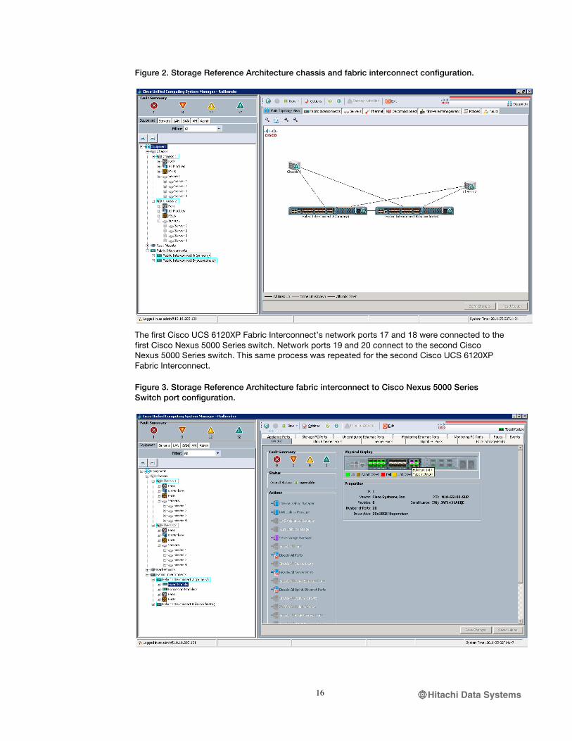
Two Cisco UCS 5108 Chassis were provisioned with four Cisco UCS B200-M2 Blade Servers and two Cisco UCS 6120XP 20-Port Fabric Interconnects. Two blade servers were installed in chassis slots 1 and 2 of each chassis. Each chassis contains eight, 10 Gigabit server ports. Ports 1 through 4 of the first chassis were connected to ports 1 through 4 on the first fabric interconnect. Ports 5 through 8 on the first chassis were connected to ports 1 through 4 on the second fabric interconnect. The same process was repeated for the second chassis using ports 5 through 8 in the fabric interconnects. All network, storage (FCoE), and management traffic used the 10 Gigabit ports. This physical topology provides a highly available connection between the Cisco UCS and the fabric.
Hitachi Data Systems16
Figure 2. Storage Reference Architecture chassis and fabric interconnect configuration.
The first Cisco UCS 6120XP Fabric Interconnect’s network ports 17 and 18 were connected to the first Cisco Nexus 5000 Series switch. Network ports 19 and 20 connect to the second Cisco Nexus 5000 Series switch. This same process was repeated for the second Cisco UCS 6120XP Fabric Interconnect.
Figure 3. Storage Reference Architecture fabric interconnect to Cisco Nexus 5000 Series Switch port configuration.
Hitachi Data Systems17
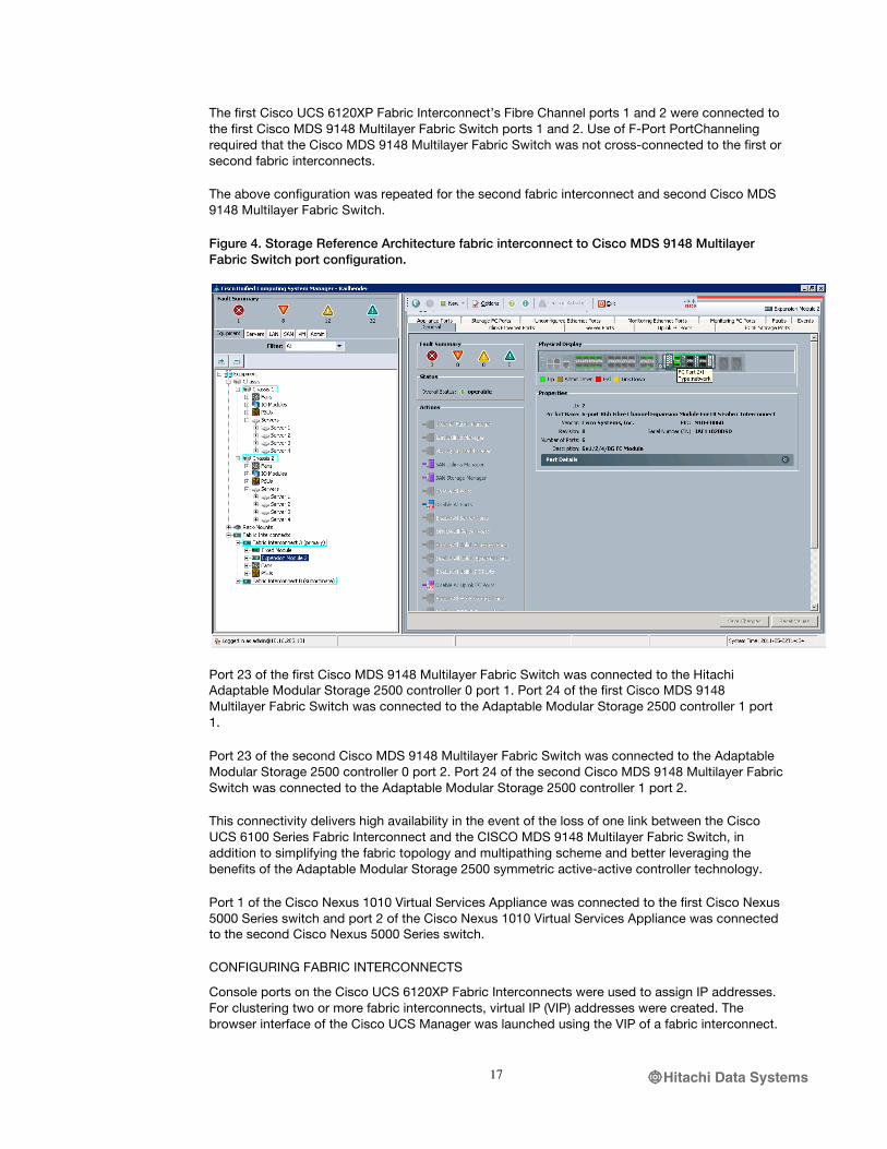
The first Cisco UCS 6120XP Fabric Interconnect’s Fibre Channel ports 1 and 2 were connected to the first Cisco MDS 9148 Multilayer Fabric Switch ports 1 and 2. Use of F-Port PortChanneling required that the Cisco MDS 9148 Multilayer Fabric Switch was not cross-connected to the first or second fabric interconnects.
The above configuration was repeated for the second fabric interconnect and second Cisco MDS 9148 Multilayer Fabric Switch.
Figure 4. Storage Reference Architecture fabric interconnect to Cisco MDS 9148 Multilayer Fabric Switch port configuration.
Port 23 of the first Cisco MDS 9148 Multilayer Fabric Switch was connected to the Hitachi Adaptable Modular Storage 2500 controller 0 port 1. Port 24 of the first Cisco MDS 9148 Multilayer Fabric Switch was connected to the Adaptable Modular Storage 2500 controller 1 port 1.
Port 23 of the second Cisco MDS 9148 Multilayer Fabric Switch was connected to the Adaptable Modular Storage 2500 controller 0 port 2. Port 24 of the second Cisco MDS 9148 Multilayer Fabric Switch was connected to the Adaptable Modular Storage 2500 controller 1 port 2.
This connectivity delivers high availability in the event of the loss of one link between the Cisco UCS 6100 Series Fabric Interconnect and the CISCO MDS 9148 Multilayer Fabric Switch, in addition to simplifying the fabric topology and multipathing scheme and better leveraging the benefits of the Adaptable Modular Storage 2500 symmetric active-active controller technology.
Port 1 of the Cisco Nexus 1010 Virtual Services Appliance was connected to the first Cisco Nexus 5000 Series switch and port 2 of the Cisco Nexus 1010 Virtual Services Appliance was connected to the second Cisco Nexus 5000 Series switch.
CONFIGURING FABRIC INTERCONNECTS
Console ports on the Cisco UCS 6120XP Fabric Interconnects were used to assign IP addresses. For clustering two or more fabric interconnects, virtual IP (VIP) addresses were created. The browser interface of the Cisco UCS Manager was launched using the VIP of a fabric interconnect.

Hitachi Data Systems18
Figure 5. Storage Reference Architecture Cisco UCS Manager home screen.
Figure 6. Storage Reference Architecture Cisco UCS Manager browser interface.
Profiles were configured in the Cisco UCS Manager using the Server, LAN and SAN tabs on the top left of the screen. Ports in the SAN section were configured first, and static port speeds (2, 4, 8, or 10) were used, following best practices.

Hitachi Data Systems19
CISCO UCS MANAGEMENT SETUP AND POOL DEFINITIONS
The Cisco UCS Manager setup and pool definitions for the Storage Reference Architecture test environment were implemented using Cisco UCS best practices as documented in production examples and tech notes (Production examples and tech notes, available at: http://www.cisco.com/en/US/products/ps10281/prod_configuration_examples_list.html)
HITACHI ADAPTABLE MODULAR STORAGE 2500 SETUP
After installing the Hitachi Adaptable Modular Storage 2500 hardware Hitachi Storage Navigator Modular 2 was used to configure the array. Prerequisites were:
Install JAVA JRE 1.6.0 for Windows applications
Install Storage Navigator Modular 2 from CD-ROM
Start Storage Navigator Modular 2 using a web browser
Use Add Array Wizard to register the storage system.
Installation Requirements
Storage Navigator Modular 2 can be run from the primary management server or client PC. It is designed on common web-based client-server technology using a standard IP network. Before the installation starts it is necessary to record the IP addresses of the Hitachi Adaptable Modular Storage 2500 or use ‘ipconfig’ to get the IP address.
Java was set in Windows as follows:
Start->Control Panel -> Java -> (Java Applet Runtime Settings) View – Java Runtime Parameter -> Xmx192m
The device running Storage Navigator Modular 2 must use a static IP address, rather than DHCP.
Table 2. Hitachi Storage Navigator Modular 2 installation requirements.
Hitachi Storage Navigator Modular 2 Description
Server Client Network I/F 100Base or 1000Base to
connect to the storage system and SNM2 client
100Base or 1000Base to connect to the SNM2 server
OS MS Windows 2008 EE
Storage software Storage Navigator Modular 2 version 9.7.7
RAM 2 GB or higher is recommended 2 GB or more
Free disk space 1.5 GB or more to install
CPU 2 GHz recommended
Other CD-ROM/DVD to install Storage Navigator Modular 2
JRE (Java Runtime Environment) 1.6 update 25 or latest version
Hitachi Data Systems20
Configuration
The Storage Navigator Modular 2 graphical interface was used to configure the Hitachi Adaptable Modular Storage 2500, using the following steps
1. Perform Initial setup
• Setup Managements ports
• Setup host ports
• Setup spare drives
• Set data/time
• Setup email alerts
2. Install license keys 3. Create the RAID group and LUNs
• Create RAID group
• Create LUNs
4. Format LUNs 5. Create host groups and setup 6. Map LUNs to hosts.
Initial Setup
A browser was pointed to the web interface of the Storage Navigator Modular 2, using the following URL:
http://<IP Address of host>:23015/StorageNavigatorModular/Login
Figure 7 shows first step in configuring the array, Initial Setup.

Hitachi Data Systems21
Figure 7. Hitachi Storage Navigator Modular 2 Initial Setup.
Setup Management Ports
The IP address of the controllers was entered in the Setup Management Ports step. The default is dual controllers, but the IP address can be modified manually— as shown in Figure 8.

Hitachi Data Systems22
Figure 8. Hitachi Storage Navigator Modular 2 Array Setup Wizard.
Host Port Setup
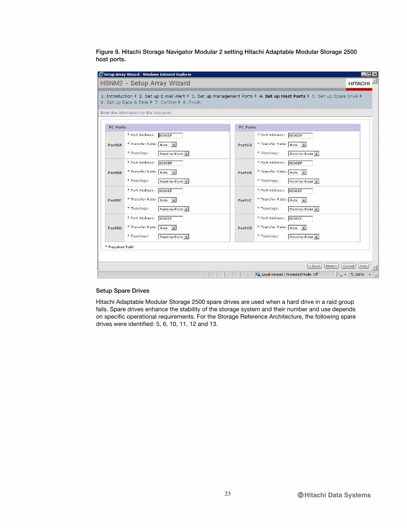
The Hitachi Adaptable Modular Storage 2500 has 4 Fibre Channel ports for each controller. These are named 0A, 0B, 0C, 0D , 1A, 1B, 1C, and 1D. Ports are configured as point-to-point. Each array owns its World Wide Name (WWN) generated from specific bits which determine its storage family and model. The WWN also contains the array's serial number. The last digit of the WWN identifies the port. Figure 9 shows how the host port was set.
Hitachi Data Systems23
Figure 9. Hitachi Storage Navigator Modular 2 setting Hitachi Adaptable Modular Storage 2500 host ports.
Setup Spare Drives
Hitachi Adaptable Modular Storage 2500 spare drives are used when a hard drive in a raid group fails. Spare drives enhance the stability of the storage system and their number and use depends on specific operational requirements. For the Storage Reference Architecture, the following spare drives were identified: 5, 6, 10, 11, 12 and 13.

Hitachi Data Systems24
Figure 10. Hitachi Storage Navigator Modular 2 setting spare drives.
Figure 7 through 10 above illustrate the basic steps followed to initialize the Hitachi Adaptable Modular Storage 2500, from setting management ports to configuring Fibre Channel ports.
Creating RAID Groups and LUNs
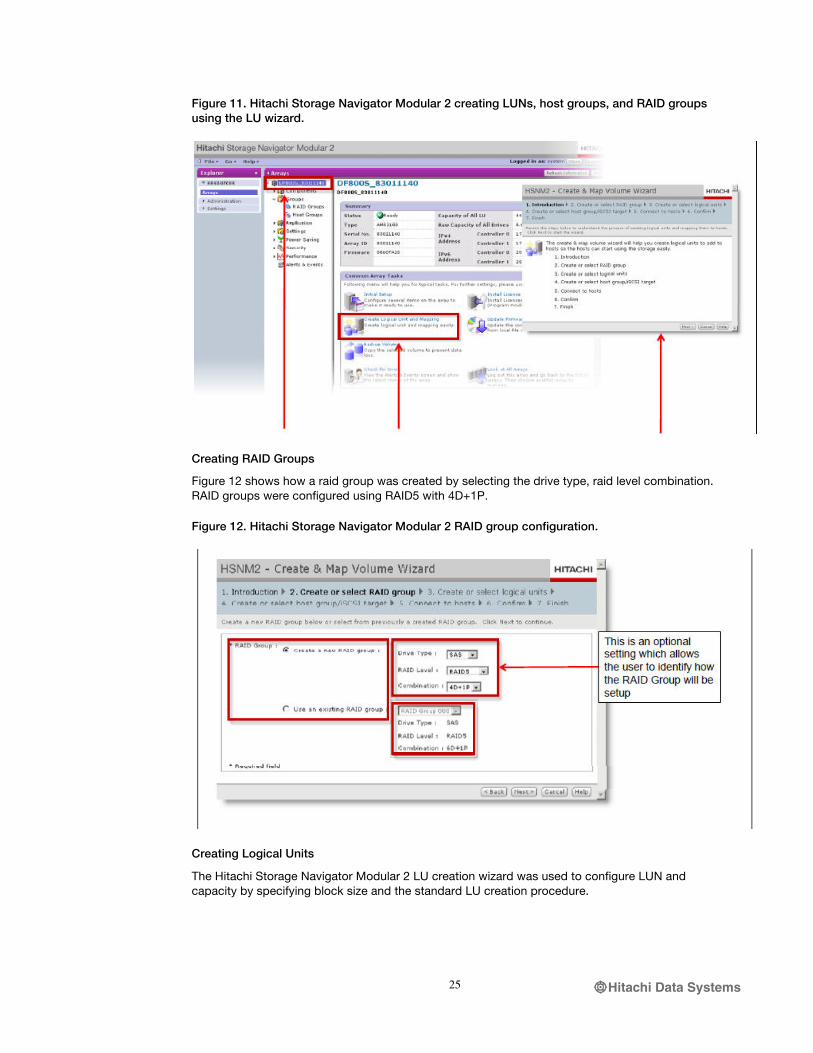
Hitachi Storage Navigator Modular 2 provides an LU wizard for creating LUNs, host groups and RAID groups, as shown in Figure 11.
Hitachi Data Systems25
Figure 11. Hitachi Storage Navigator Modular 2 creating LUNs, host groups, and RAID groups using the LU wizard.
Creating RAID Groups
Figure 12 shows how a raid group was created by selecting the drive type, raid level combination. RAID groups were configured using RAID5 with 4D+1P.
Figure 12. Hitachi Storage Navigator Modular 2 RAID group configuration.
Creating Logical Units
The Hitachi Storage Navigator Modular 2 LU creation wizard was used to configure LUN and capacity by specifying block size and the standard LU creation procedure.

Hitachi Data Systems26
Figure 13. Hitachi Storage Navigator Modular 2 LUN creation.
Creating Host Groups
Host groups are management entities which establish connectivity between host and storage through port definitions. Host groups can be configured individually on a LUN or within a Hitachi Dynamic Provisioning group.
Before creating a host group it is necessary to enable Host Group Security for front-end FC ports.
For this configurtion, four Dynamic Provisioning host groups were configured, as shown in Figure 14.
Figure 14. Hitachi Storage Navigator Modular 2 configuring host groups within Hitachi Dynamic Provisioning pools.
Each RAID group is a building block containing LUNs and is configured to provide storage for users. Connecting the LUNs on the Hitachi Adaptable Modular Storage 2500 to hosts requires creating host groups.

Hitachi Data Systems27
Host groups are created in Hitachi Storage Navigator Modular 2 LUN manager. The LUN manager determines host accessibility to LUNs using host group, Adaptable Modular Storage 2500 port WWNs, and the platform—in this configuration the VMware vSphere ESX servers running on the four Cisco UCS B200 M2 Blade Servers. This process associates Adaptable Modular Storage 2500 ports with LUNS.
Figure 15 illustrates the host group, port, and platform configuration used.
Figure 15. Hitachi Storage Navigator Modular 2 associating host groups, ports, and platforms.
Host groups were created using Hitachi Storage Navigator Modular 2 Create and Map Volume Wizard.

Hitachi Data Systems28
Figure 16. Hitachi Storage Navigator Modular 2 Create and Map Volume Wizard.
Having defined the basic elements, host group were associated with host HBA WWNs to determine a path to the host.
Note that WWNs associated with the Cisco UCS start with 20 on the first octet and differentiates in its 6th octet if it is a nodename (00), an hba0 (A1) or hba1 (B1). Figure 17 shows host groups associated with hba0.

Hitachi Data Systems29
Figure 17. Hitachi Storage Navigator Modular 2 host group associations.
LUN provisioning
Each LUN can be created in a RAID group or a Hitachi Dynamic Provisioning pool and assigned to a host group. A Dynamic Provisioning pool consists of multiples drives within a RAID group. The pool may include one or more Dynamic Provisioning RAID groups.
In the Storage Reference Architecture configuration, Hitachi Adaptable Modular Storage 2500 LUNs were created from Dynamic Provisioning pools with RAID-5, consisting of all SAS drives. Each 1.9 TB LUN was created from a Dynamic Provisioning pool.

Hitachi Data Systems30
Figure 18. Hitachi Storage Navigator Modular 2 LUN provisioning.
The steps outlined in this section show how the Hitachi Adaptable Modular Storage 2500 was set up and configured.
SAN PROVISIONING
Cisco UCS fuses access layer networking and servers. This gives the data center a high degree of workload agility and scalability.
The hardware and software components in the Cisco UCS support a unified fabric, which allows multiple types of data center traffic over a single physical Ethernet network. This Data Center Ethernet (DCE) technology reduces the amount of cabling, management, and cost with the combination of the host bus adapters (HBAs) and network interface cards (NICs) into a single adapter called the Converged Network Adapter (CNA). This adapter can carry LAN and SAN traffic on the same cable.
Cisco UCS uses Fibre Channel over Ethernet (FCoE) protocol to carry Fibre Channel (FC) traffic inside Ethernet frame. Cisco UCS also adheres to multiple 802.1 standards to provide the DCE underlying the FCoE to effectively transport those frames. The fabric interconnect separates the LAN and SAN traffic from the Ethernet frames and forwards them to the appropriate network ports. This gives the flexibility to deploy this technology without the need of implementing the unified fabric solution across the entire data center network.
Cisco UCS blade servers installed with Cisco UCS M71KR-E Emulex Converged Network Adapter or Cisco UCS M71KR-Q QLogic Converged Network Adapter can handle both Fibre Channel and IP traffic simultaneously. The converged network adapter presents an Ethernet interface and a Fibre Channel interface to the operating system. The operating system is completely unaware of the encapsulation taking place in the Ethernet segment. The only requirement is for the operating system to have the appropriate drivers to recognize the converged network adapter hardware.
At the fabric interconnect, the server-facing Ethernet port receives the Ethernet and Fibre Channel traffic. The fabric interconnect (which uses Ethertype to differentiate the frames) separates the two traffic types. Ethernet frames and Fibre Channel frames are switched to their respective uplink interfaces.
Hitachi Data Systems31
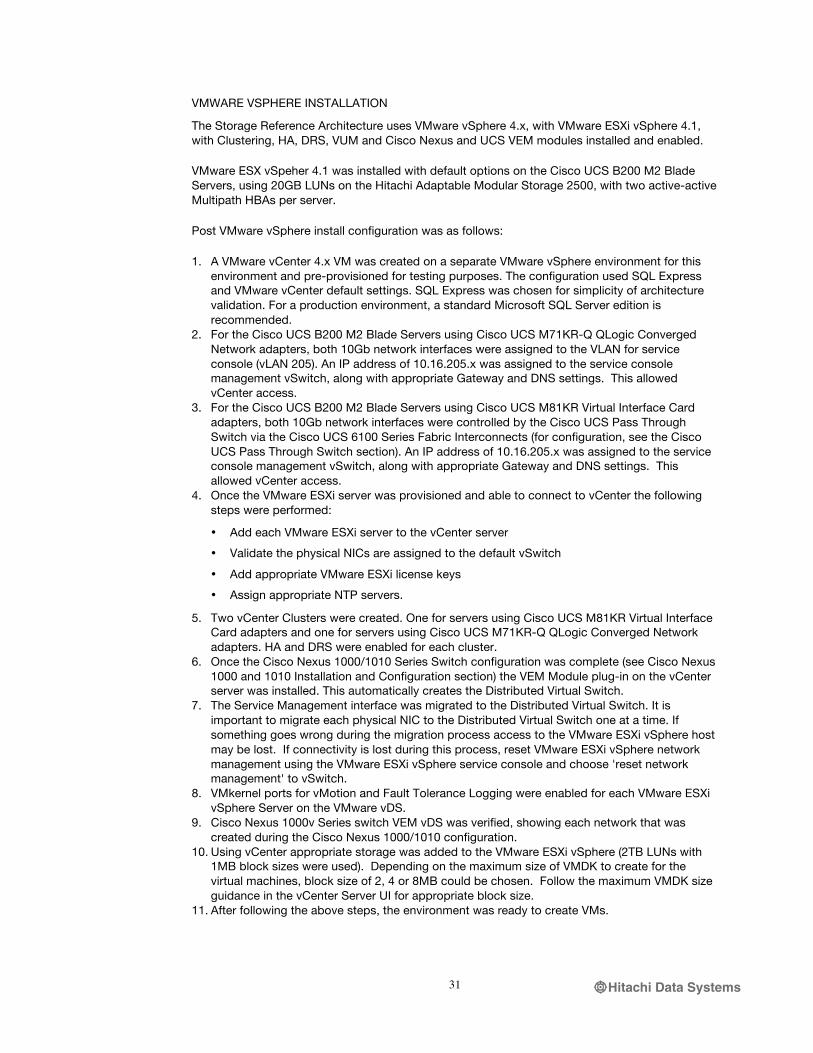
VMWARE VSPHERE INSTALLATION
The Storage Reference Architecture uses VMware vSphere 4.x, with VMware ESXi vSphere 4.1, with Clustering, HA, DRS, VUM and Cisco Nexus and UCS VEM modules installed and enabled.
VMware ESX vSpeher 4.1 was installed with default options on the Cisco UCS B200 M2 Blade Servers, using 20GB LUNs on the Hitachi Adaptable Modular Storage 2500, with two active-active Multipath HBAs per server.
Post VMware vSphere install configuration was as follows:
1. A VMware vCenter 4.x VM was created on a separate VMware vSphere environment for this environment and pre-provisioned for testing purposes. The configuration used SQL Express and VMware vCenter default settings. SQL Express was chosen for simplicity of architecture validation. For a production environment, a standard Microsoft SQL Server edition is recommended.
2. For the Cisco UCS B200 M2 Blade Servers using Cisco UCS M71KR-Q QLogic Converged Network adapters, both 10Gb network interfaces were assigned to the VLAN for service console (vLAN 205). An IP address of 10.16.205.x was assigned to the service console management vSwitch, along with appropriate Gateway and DNS settings. This allowed vCenter access.
3. For the Cisco UCS B200 M2 Blade Servers using Cisco UCS M81KR Virtual Interface Card adapters, both 10Gb network interfaces were controlled by the Cisco UCS Pass Through Switch via the Cisco UCS 6100 Series Fabric Interconnects (for configuration, see the Cisco UCS Pass Through Switch section). An IP address of 10.16.205.x was assigned to the service console management vSwitch, along with appropriate Gateway and DNS settings. This allowed vCenter access.
4. Once the VMware ESXi server was provisioned and able to connect to vCenter the following steps were performed:
• Add each VMware ESXi server to the vCenter server
• Validate the physical NICs are assigned to the default vSwitch
• Add appropriate VMware ESXi license keys
• Assign appropriate NTP servers.
5. Two vCenter Clusters were created. One for servers using Cisco UCS M81KR Virtual Interface Card adapters and one for servers using Cisco UCS M71KR-Q QLogic Converged Network adapters. HA and DRS were enabled for each cluster.
6. Once the Cisco Nexus 1000/1010 Series Switch configuration was complete (see Cisco Nexus 1000 and 1010 Installation and Configuration section) the VEM Module plug-in on the vCenter server was installed. This automatically creates the Distributed Virtual Switch.
7. The Service Management interface was migrated to the Distributed Virtual Switch. It is important to migrate each physical NIC to the Distributed Virtual Switch one at a time. If something goes wrong during the migration process access to the VMware ESXi vSphere host may be lost. If connectivity is lost during this process, reset VMware ESXi vSphere network management using the VMware ESXi vSphere service console and choose 'reset network management' to vSwitch.
8. VMkernel ports for vMotion and Fault Tolerance Logging were enabled for each VMware ESXi vSphere Server on the VMware vDS.
9. Cisco Nexus 1000v Series switch VEM vDS was verified, showing each network that was created during the Cisco Nexus 1000/1010 configuration.
10. Using vCenter appropriate storage was added to the VMware ESXi vSphere (2TB LUNs with 1MB block sizes were used). Depending on the maximum size of VMDK to create for the virtual machines, block size of 2, 4 or 8MB could be chosen. Follow the maximum VMDK size guidance in the vCenter Server UI for appropriate block size.
11. After following the above steps, the environment was ready to create VMs.

Hitachi Data Systems32
Installing and Configuring Cisco Nexus 1000v and 1010
Cisco Nexus 1000v/1010 Series Switches deliver highly secure, multitenant services by adding virtualization intelligence to the data center network. The Cisco Nexus 1000v/1010 Series comprises two components:
• Virtual Ethernet Module (VEM), a software switch embedded in the VMware hypervisor
• Virtual Supervisor Module (VSM), which manages networking policies and quality of service for virtual machines in concert with the VEM
The Cisco Nexus 1000V/1010 Switch can optimize the use of Layer 4-7 services in a virtual machine environment through Cisco vPath architecture services.
Cisco vPath technology is aware of all Layer 4-7 policies associated with individual virtual machines. Once the data packets of a specific virtual machine have been identified and policies applied, the remaining data packets flow directly to the virtual machines.
The Cisco Nexus 1010 networking appliance hosts four Cisco Nexus 1000v virtual supervisor modules (VSMs) and a Cisco Network Analysis Module (NAM). The Cisco Nexus 1010 provides dedicated hardware for the VSM. VSMs that were hosted on VMware virtual machines can now be hosted on a Cisco Nexus 1010 appliance. This configuration permits installation and management of the VSM like a standard Cisco switch. The modules (VSM or NAM) managed by the Cisco Nexus 1010 are called virtual service blades (VSBs).
The step by step instructions followed to install and configure the Cisco Nexus 1000v Switch and Cisco Nexus 1010 appliance are available at: http://www.cisco.com/en/US/products/ps9902/products_installation_and_configuration_guides_list.html
CISCO UCS PASS THROUGH SWITCHING CONFIGURATION
The pass-through switch (PTS) is a Cisco UCS feature allowing management of the virtual network and configuration of virtual ports by Cisco UCS manager. This feature does not require a license and is available at no additional cost for any blade using the Cisco UCS M81KR Virtual Interface Card adapter. PTS does not require Hypervisor Bypass/Direct-Path I/O but can be used in conjunction with it, although there are current limitations, such as no vMotion. PTS utilizes a Cisco software switching element within the hypervisor much like a Cisco Nexus 1000v VEM. All management/supervisor capabilities are handled within Cisco UCS Manager on the fabric interconnects. PTS provides a 1-to-1 mapping between a virtual machines NIC, vNIC, and a Virtual Interface (VIF) on the virtual interface card. This allows for VM level granularity for network monitoring and control while maintaining the single point of management at the UCSM.
Requirements
• VMware ESX/ESXi vSphere 4.1 installed on all participating blades
• Cisco virtual interface card in each participating blade
• Virtual Center Server
• VMware Enterprise Plus licensing (required for vDS usage)
Recommended
• VMware Update Manager (VUM)
• Latest Cisco Nexus 1000v Series Switch packages downloaded to VUM repository and a baseline created in VUM that contains the appropriate updates/patches for the ESX build number

Hitachi Data Systems33
• Current Cisco Nexus 1000v Series switch bundle downloaded from Cisco if VUM is not available—If VUM is not used the VEM will need to be manually installed per host.
Installation Steps
1. A Dynamic vNIC policy was created within the Cisco UCS Manager (LAN tab)
a. Provide a name
b. Select the number of ports (typically the default of 54 which is the max)
c. Select VMware for the port type
2. A template or service profile was created for each participate host, using the dynamic vNIC policy. Alternately the policy can be applied to an existing service profile or updating template.
3. The profile was applied to the Cisco UCS B200 M2 Blade Servers blades acting as VMware hosts that contain the VIC.
It is recommended that the service profile be configured to pass 4 virtual Ethernet (vEth) ports. Two to be attached to a standard vSwitch and used for all VMkernel ports in use, and two to be used as uplinks to the vDS, carrying VM Guest data traffic.
Cisco UCS Manager allows for many different methods to complete the next steps and the latest release of the UCS Manager provides a wizard to assist with the process. The steps below were followed to configure the reference architecture.
4. Cisco UCS Manager and vCenter server were connected and authenticated as follows:
a. From the VM tab within Cisco UCS Manager click on “Export vCenter Extension,” save the file to a location accessible by both systems (typically the desktop.) This is an XML file that contains all the information used to authenticate Cisco UCS Manager with vCenter and allow API calls.
b. Import the file as a vCenter server plugin through the VMware vSphere client. Right-click on white space below all other plugins and select Register Plugin.
5. vCenter connection information was set up in Cisco UCS Manager as follows
a. From the VM tab within Cisco UCS Manager click on the “Configure vCenter” link
b. Provide a descriptive name. It is recommended the name match the vCenter name for ease of use.
c. Provide the hostname or IP of the VMware vCenter server. IP is recommended for statically assigned VMware vCenter server IPs, if DNS hostname is selected, ensure name resolution is configured in Cisco UCS Manager.
d. Next, skip the folder settings and next again.
e. Click Add on the Datacenter screen
f. Provide a descriptive name. It is recommended the name matches the vCenter Datacenter name for ease of use.
g. Add a folder, this will contain the distributed virtual switch (DVS), Next
h. Add the DVS, this is what is pushed into vCenter
i. Click Ok, Finish, then Finish again.
Hitachi Data Systems34
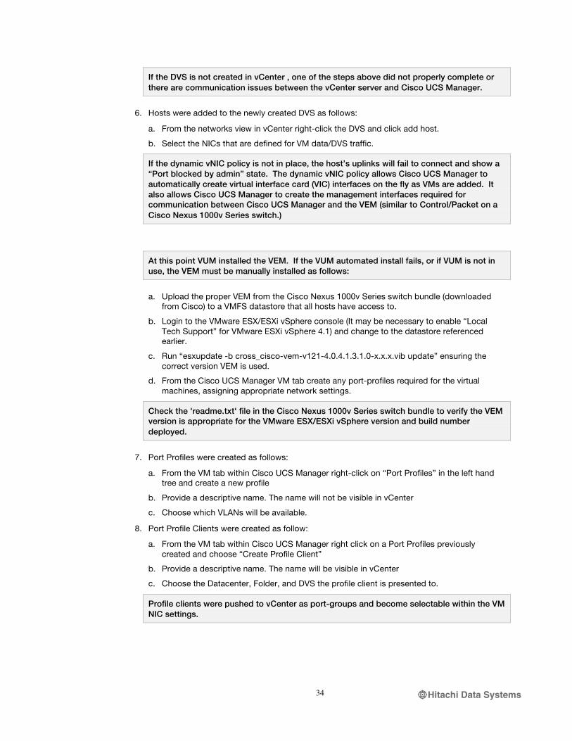
If the DVS is not created in vCenter , one of the steps above did not properly complete or there are communication issues between the vCenter server and Cisco UCS Manager.
6. Hosts were added to the newly created DVS as follows:
a. From the networks view in vCenter right-click the DVS and click add host.
b. Select the NICs that are defined for VM data/DVS traffic.
If the dynamic vNIC policy is not in place, the host’s uplinks will fail to connect and show a “Port blocked by admin” state. The dynamic vNIC policy allows Cisco UCS Manager to automatically create virtual interface card (VIC) interfaces on the fly as VMs are added. It also allows Cisco UCS Manager to create the management interfaces required for communication between Cisco UCS Manager and the VEM (similar to Control/Packet on a Cisco Nexus 1000v Series switch.)
At this point VUM installed the VEM. If the VUM automated install fails, or if VUM is not in use, the VEM must be manually installed as follows:
a. Upload the proper VEM from the Cisco Nexus 1000v Series switch bundle (downloaded from Cisco) to a VMFS datastore that all hosts have access to.
b. Login to the VMware ESX/ESXi vSphere console (It may be necessary to enable “Local Tech Support” for VMware ESXi vSphere 4.1) and change to the datastore referenced earlier.
c. Run “esxupdate -b cross_cisco-vem-v121-4.0.4.1.3.1.0-x.x.x.vib update” ensuring the correct version VEM is used.
d. From the Cisco UCS Manager VM tab create any port-profiles required for the virtual machines, assigning appropriate network settings.
Check the 'readme.txt' file in the Cisco Nexus 1000v Series switch bundle to verify the VEM version is appropriate for the VMware ESX/ESXi vSphere version and build number deployed.
7. Port Profiles were created as follows:
a. From the VM tab within Cisco UCS Manager right-click on “Port Profiles” in the left hand tree and create a new profile
b. Provide a descriptive name. The name will not be visible in vCenter
c. Choose which VLANs will be available.
8. Port Profile Clients were created as follow:
a. From the VM tab within Cisco UCS Manager right click on a Port Profiles previously created and choose “Create Profile Client”
b. Provide a descriptive name. The name will be visible in vCenter
c. Choose the Datacenter, Folder, and DVS the profile client is presented to.
Profile clients were pushed to vCenter as port-groups and become selectable within the VM NIC settings.
Hitachi Data Systems35
USE CASES
The Storage Reference Architecture from Cisco, Hitachi and VMware is applicable to a wide variety of use cases. Below are three examples.
PRIVATE CLOUD APPLICATION SERVER FARM
During the last decade IT organizations across the globe have transformed themselves in an effort to focus on delivering IT as a service. These transformations have typically followed a common path:
1. Consolidate and virtualize infrastructure, development, and test environments. Target workloads include file, print server, development and test environment.
2. Virtualize tier-1 business critical applications, with the goal of increasing resource utilization rates. Application targets include Microsoft Exchange, Microsoft SQL Server, and Microsoft Sharepoint.
3. Deliver IT as a service. Highly automated, service-oriented delivery using a cloud infrastructure.
IT organizations are also seeing a proliferation of middleware and application server requests from the businesses they support. The modern N-tier application architecture relies heavily on a scale-out model, using industry-standard x86 compute nodes and dynamically provisioned storage and network resources. These can accommodate the extra power needed to drive today’s application clusters. Business applications vary widely in their functionality, but typically have similar hardware requirements. These requirements lend themselves to being supported by a server farm of virtualized compute, storage, and network resources.
To accomplish service delivery goals and satisfy application requirements, IT organizations need a resilient, operationally efficient, scalable infrastructure that pools IT resources using virtualization.
The Storage Reference Architecture offers the benefits of service-oriented delivery by providing a virtualized cloud infrastructure. It provides enterprise-class features competitively priced for small- and medium-sized businesses.
All components of the Storage Reference Architecture are designed to support rapid, consistent, and automated provisioning of IT resources, whether for new functionality or to add power to existing applications. The Cisco UCS 6100 Series Virtual Interface Card allows any given Cisco UCS B200 M2 Blade Server to provide exactly the number of NICs and HBAs the application requires. Additionally, these environments frequently require the ability to quickly clone the application stack for testing, QA, staging, and development purposes. Specific features in the Storage Reference Architecture, such as Service Profile abstraction and cloning, VAAI-enhanced VM copies, pass-though switching, and integrated network management, provide operations teams with immediate benefits for delivering improved application services.
Because the underlying hardware is typically shared by multiple applications—or even organizations, in the case of service providers—in order to help drive up efficient utilization rates, the infrastructure must be highly resilient without any single point of failure lest a problem affect multiple applications. The Storage Reference Architecture ensures enterprise-class availability for the entire application farm through its fully redundant design, from the compute infrastructure all the way through the network to the storage. To minimize maintenance impact, workloads can easily be migrated from one component of the infrastructure to another using VMotion and Service Profile abstraction to ensure consistent deployments.
Finally, as businesses grow, require additional functionality, and upgrade resources, application server needs change. Delivering resources and service levels across multiple applications and lines of business while maintaining a highly efficient and cost-effective infrastructure demands a systematic model for infrastructure management.

Hitachi Data Systems36
The Storage Reference Architecture provides a simple operational management model for the entire application farm, with centralized management points in Cisco UCS Manager, Hitachi Storage Navigator Modular 2, and VMWare vCenter. Compute, storage, network, and operating systems are easily managed as resources through these centralized consoles allowing IT organizations to maintain control over a large private cloud application farm with minimal human resourcing and a consistent operational model.
APPLICATION DEVELOPMENT SERVER FARM
Businesses have invested significantly in IT technology to gain competitive advantage. However, small and midsize organizations often find it difficult to gain the maximum benefit from new technologies. Along with high operational and administrative costs, the need for infrastructure stratification—development, staging, quality assurance, and production environments—adds complexity and further raises costs. A virtualized server farm, using VMware, Cisco, and Hitachi components, reduces complexity and ensures efficient and cost-effective use of the available resources.
The Storage Reference Architecture enables rapid and automated deployment of large amounts of compute resource with the VAAI full-copy and the Cisco UCS XML API. Together these integrated tools can clone VMs or datastores using templates and offload read/write operations to the storage system. The VAAI capabilities of the Hitachi Adaptable Modular Storage 2500 support rapid deployment of development servers in a controlled environment. Furthermore, block-zeroing capability reduces server workload by offloading zero write operations to the Adaptable Modular Storage 2500 and accelerating the provisioning of new VMs.
In a QA environment, developers performing application stress tests often encounter IO bottlenecks when multiple hosts access the same storage LUN. This results in SCSI reservation conflicts. VMware relies on locking mechanisms to protect metadata in clustered environments. By transferring this locking mechanism to the Adaptable Modular Storage 2500, access to a lock is granted at the disk sector level. This increases the overall scalability of multiple hosts connected to the same underlying storage.
For IT organizations that cannot afford downtime to service or upgrade hardware, vMotion provides the capability to live migrate running virtual machines from one VMware ESX host to another. This effectively eliminates planned outages for migration. Once the workload has been moved from one ESX host to another, hardware service or maintenance can be performed without impacting users.
VIRTUAL DESKTOP INFRASTRUCTURE
Many enterprise organizations are using the VMware virtual desktop infrastructure (VDI) to reduce the cost of operations and provide higher levels of availability to users. In addition to obvious cost and maintenance advantages, VDI offers easy scalability and enhanced performance benefits. An integrated infrastructure is essential to gaining the advantages of VDI.
The Storage Reference Architecture clearly demonstrates how Cisco, Hitachi, and VMware work together to ensure a dependable and integrated virtualized infrastructure. The Cisco UCS hardware provides a highly available platform for running VMware ESXi hosts, which are the backbone of VDI. Cisco Nexus Family switches and Cisco MDS 9148 Multilayer switch hardware and the Hitachi Adaptable Modular Storage 2500 illustrate how networking and storage fabrics can be configured for scalability, performance, and high availability.
VAAI integration between VMware and Hitachi storage greatly improves the scalability and performance of the infrastructure, by reducing CPU utilization of the ESX hosts running on Cisco UCS B200 M2 Blade Servers and by reducing provisioning time. The use of active-active IO techniques allows more resiliency and operational performance by taking components that would otherwise sit idle and putting them to work.

Hitachi Data Systems37
The Cisco UCS platform uses FCoE and active-active fabric interconnects to enable servers to use all components of the environment simultaneously. This increases scalability of the infrastructure and minimizes downtime to VDI users.

Hitachi Data Systems38
VALIDATION RESULTS
The Storage Reference Architecture system design was validated in the lab, focusing on resiliency, operational performance, high availability, and enhanced capabilities. This addresses the deployment issues customers typically face.
HIGH AVAILABILITY TEST RESULTS
High Availability was evaluated by simulating physical device failures while running traffic load on the system (using Zoltes IOmeter). The system was monitored before, during, and after each simulated failure event to ensure continuous operation. The following failures were simulated;
Table 3. Validation Test: simulated component failure.
Simulated Component Failure Result UCS IO Module Pass Fabric Interconnect (6100) Pass Fabric Interconnect SAN uplink Pass MDS SAN switch Pass Nexus 5000 switch Pass HDS AMS2500 controller Pass ESX Host Pass
VAAI AND HITACHI ADAPTABLE MODULAR STORAGE 2500 VALIDATION RESULTS
Increased VM Density
Reduce Host IO With VAAI Full Copy
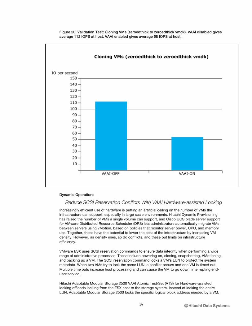
Enabling VAAI dramatically reduces IO between the VMware ESX nodes and the storage system when cloning a VM from zeroedthick to zeroedthick virtual machine disk format (VMDK). With VAAI enabled, the constant read/write operations typical of the cloning process are offloaded from the VMware ESX host to the Hitachi Adaptable Modular Storage 2500. This reduces host-side IO, significantly improving VM performance and allowing greater VM density (more VMs supported by the same infrastructure). Figure 20 illustrates reduced host IOPS when performing a full-copy with VAAI enabled versus VAAI disabled.
Hitachi Data Systems39
Figure 20. Validation Test: Cloning VMs (zeroedthick to zeroedthick vmdk). VAAI disabled gives average 112 IOPS at host. VAAI enabled gives average 58 IOPS at host.
Dynamic Operations
Reduce SCSI Reservation Conflicts With VAAI Hardware-assisted Locking
Increasingly efficient use of hardware is putting an artificial ceiling on the number of VMs the infrastructure can support, especially in large scale environments. Hitachi Dynamic Provisioning has raised the number of VMs a single volume can support, and Cisco UCS blade server support for VMware Distributed Resource Scheduler (DRS) lets administrators automatically migrate VMs between servers using vMotion, based on policies that monitor server power, CPU, and memory use. Together, these have the potential to lower the cost of the infrastructure by increasing VM density. However, as density rises, so do conflicts, and these put limits on infrastructure efficiency.
VMware ESX uses SCSI reservation commands to ensure data integrity when performing a wide range of administrative processes. These include powering on, cloning, snapshotting, VMotioning, and backing up a VM. The SCSI reservation command locks a VM’s LUN to protect file system metadata. When two VMs try to lock the same LUN, a conflict occurs and one VM is timed out. Multiple time outs increase host processing and can cause the VM to go down, interrupting end-user service.
Hitachi Adaptable Modular Storage 2500 VAAI Atomic Test/Set (ATS) for Hardware-assisted locking offloads locking from the ESX host to the storage system. Instead of locking the entire LUN, Adaptable Modular Storage 2500 locks the specific logical block address needed by a VM.
Hitachi Data Systems40
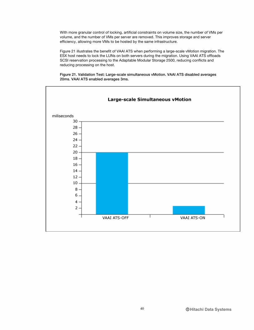
With more granular control of locking, artificial constraints on volume size, the number of VMs per volume, and the number of VMs per server are removed. This improves storage and server efficiency, allowing more VMs to be hosted by the same infrastructure.
Figure 21 illustrates the benefit of VAAI ATS when performing a large-scale vMotion migration. The ESX host needs to lock the LUNs on both servers during the migration. Using VAAI ATS offloads SCSI reservation processing to the Adaptable Modular Storage 2500, reducing conflicts and reducing processing on the host.
Figure 21. Validation Test: Large-scale simultaneous vMotion. VAAI ATS disabled averages 20ms. VAAI ATS enabled averages 3ms.
Hitachi Data Systems41
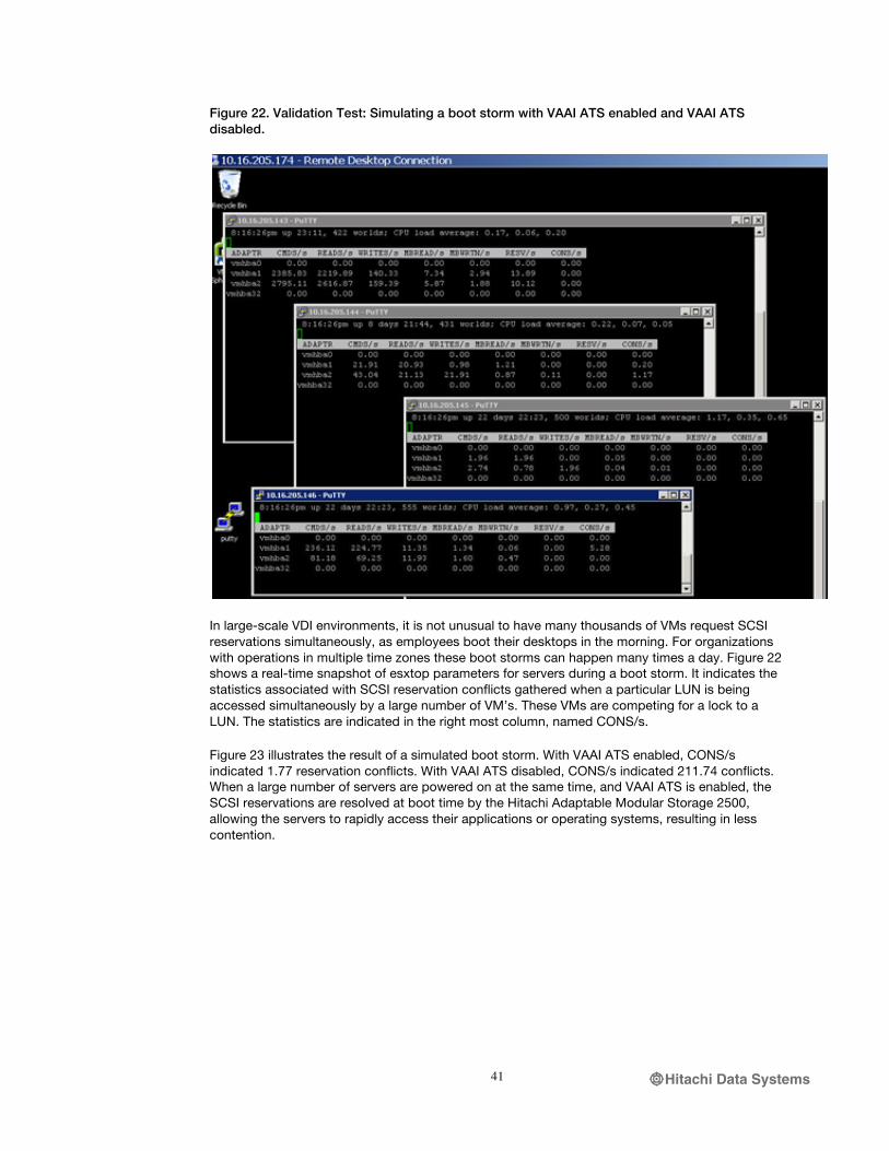
Figure 22. Validation Test: Simulating a boot storm with VAAI ATS enabled and VAAI ATS disabled.
In large-scale VDI environments, it is not unusual to have many thousands of VMs request SCSI reservations simultaneously, as employees boot their desktops in the morning. For organizations with operations in multiple time zones these boot storms can happen many times a day. Figure 22 shows a real-time snapshot of esxtop parameters for servers during a boot storm. It indicates the statistics associated with SCSI reservation conflicts gathered when a particular LUN is being accessed simultaneously by a large number of VM’s. These VMs are competing for a lock to a LUN. The statistics are indicated in the right most column, named CONS/s.
Figure 23 illustrates the result of a simulated boot storm. With VAAI ATS enabled, CONS/s indicated 1.77 reservation conflicts. With VAAI ATS disabled, CONS/s indicated 211.74 conflicts. When a large number of servers are powered on at the same time, and VAAI ATS is enabled, the SCSI reservations are resolved at boot time by the Hitachi Adaptable Modular Storage 2500, allowing the servers to rapidly access their applications or operating systems, resulting in less contention.

Hitachi Data Systems42
Figure 23. Validation Test: with VAAI ATS enabled SCSI reservation conflicts are reduced during a boot storm.
Saved Space Without Increased Performance
Reduce the Thin Provisioning Warm-up Penalty With VAAI Block Zeroing and Hitachi Dynamic Provisioning
VMware ESX supports different space allocation options when creating new VMs or virtual disks. The zeroedthick format pre-allocates virtual disk space but does not immediately write zeroes to the allocated space. The benefit of zeroedthick is fast provisioning of disk space, but it creates a warm-up penalty when the guest OS initially writes to disk. On first write, VMware ESX zeroes the allocated disk space, temporarily reducing host IOPS and increasing IO latency.
The eagerzeroedthick format eliminates zeroedthick’s warm-up penalty. Virtual disk space is pre-allocated and pre-zeroed when the storage is provisioned. However, this pre-zeroing process is time consuming and it takes much longer to provision eagerzeroedthick formatted virtual disks.
Hitachi Adaptable Modular Storage 2500 VAAI block zeroing offloads zeroing of allocated disk space from the ESX host to the storage system. This dramatically reduces the time it takes to provision eagerzeroedthick virtual disk. It also eliminates the warm-up penalty associated with the zeroedthick format and delivers the capacity savings, rapid provisioning, and performance benefits of Hitachi Dynamic Provisioning thin provisioning.

Hitachi Data Systems43
SUMMARY
As IT organizations transition to a cloud-based and service-centric infrastructure model, the need for integrated data center technologies is paramount. Hitachi Data Systems, Cisco, and VMware are industry leaders in storage, server, network, and virtualization, and understand the costs, risks, and rewards of transforming the data center. By providing a validated architecture that combines these key technologies, the Storage Reference Architecture from Hitachi, Cisco, and VMware reduces the risk of introducing new resources to the data center, speeds application and infrastructure deployment, provides greater flexibility, and is highly cost-effective.
The Storage Reference Architecture gives IT administrators and managers a blueprint for creating a scalable, cloud-ready infrastructure using technologies that have been jointly tested and validated. Combining storage, server, network, and virtualization using the Storage Reference Architecture eliminates the risk of custom integrated alternatives and provides the flexibility to build solutions that meet today’s requirements, with the confidence to scale as needs grow.

Hitachi Data Systems44
REFERENCES
HITACHI DATA SYSTEMS
Advantages of using VMware VAAI with Hitachi AMS 2000 Family - Lab Validation Report:
http://www.hds.com/assets/pdf/advantages-of-using-vmware-vaai-with-the-hitachi-ams-2000-family.pdf
Using VMware vSphere 4 with Hitachi Dynamic Provisioning Software on the Hitachi AMS 2000
family - Best Practices Guide: http://www.hds.com/assets/pdf/hitachi-dynamic-provisioning-software-using-vmware-vsphere-4.pdf
Optimizing the Hitachi AMS 2000 Family in vSphere 4 Environments - Best Practices Guide:
http://www.hds.com/assets/pdf/optimizing-the-hitachi-ams-2000-family-in-vsphere-4-environments.pdf
Storage Performance for Virtualized Tier One Applications:
http://www.hds.com/assets/pdf/storage-performance-for-virtualized-tier-one-applications.pdf
Advantages of Hitachi Adaptable Modular Storage 2000 Family Symmetric Active-active Controllers in vSphere 4 Environments - Lab Validation Report:
http://www.hds.com/go/oneforall/pdfs/advantages-of-hitachi-ams-2000-family-symmetric-active-active-controllers.pdf
Hitachi Data Systems - “Hitachi Storage Navigator Modular 2 Storage Features Reference Guide for AMS”, MK-97DF8148-13, February 2011.
Hitachi Data Systems – “Hitachi Storage Navigator Modular 2 Advanced Settings User’s Guide”, MK-97DF8039-13, February 2011.
CISCO SYSTEMS
Cisco Unified Computing and Server Products:
http://www.cisco.com/en/US/products/ps10265/products.html
Cisco Storage Networking Products:
http://www.cisco.com/en/US/products/hw/ps4159/products.html
Cisco Data Center Switching Products:
http://www.cisco.com/en/US/products/ps9441/Products_Sub_Category_Home.html
Cisco UCS chassis installation guide:
http://www.cisco.com/en/US/docs/unified_computing/ucs/hw/chassis/install/ucs5108_install.html
Cisco UCS CLI Configuration Guide:
http://www.cisco.com/en/US/docs/unified_computing/ucs/sw/cli/config/guide/1.3.1/b_CLI_Config_Guide_1_3_1.html

Hitachi Data Systems45
Step-by-Step SAN provisioning instructions:
http://www.cisco.com/en/US/products/ps10281/products_configuration_example09186a0080afd130.shtml
VMWARE
Configuration Maximums for VMware vSphere 4.1:
http://www.vmware.com/pdf/vsphere4/r41/vsp_41_config_max.pdf

Hitachi Data Systems46
PRODUCT CONFIGURATIONS
HITACHI ADAPTABLE MODULAR STORAGE 2500 CONFIG
The Hitachi Adaptable Modular Storage 2500 used in this lab has the following specifications:
• DF Name: AMS2500_87012323
• Date: 2011/03/30
• Firmware Revision: 0897/H-Z
• Array Unit Type : AMS2500
• Serial Number: 87012323
• HSNM2 Version: 9.70
RAID Configuration
RAID groups displayed in relation to physical disks are depicted in Tables 4 and 5 below.
Table 4. Hitachi Adaptable Modular Storage 2500 RAID groups allocated in each tray.
Tray D D D D P D D D D P D D D D P
0 0 1 2 3 4 5 6 7 8 9 10 11 12 13 14
1 0 1 2 3 4 5 6 7 8 9 10 11 12 13 14
2 0 1 2 3 4 5 6 7 8 9 10 11 12 13 14
3 0 1 2 3 4 5 6 7 8 9 10 11 12 13 14
DP pool 0 contains RAID groups: 98 and 99
DP pool 1 contains RAID groups: 96 and 97
DP pool 2 contains RAID groups: 94 and 95
DP Pool 3 contains RAID groups: 92 and 93
Table 5. Hitachi Adaptable Modular Storage 2500 drive location of Hitachi Dynamic Provisioning RAID group.
RG Tray HDU HDU HDU HDU HDU
95 0 0 1 2 3 4
94 0 5 6 7 8 9
93 0 10 11 12 13 14
92 1 0 1 2 3 4
1 5 6 7 8 9
1 10 11 12 13 14
99 2 0 1 2 3 4
98 2 5 6 7 8 9
97 2 10 11 12 13 14
96 3 0 1 2 3 4
3 5 6 7 8 9
Hitachi Data Systems47
3 10 11 12 13 14
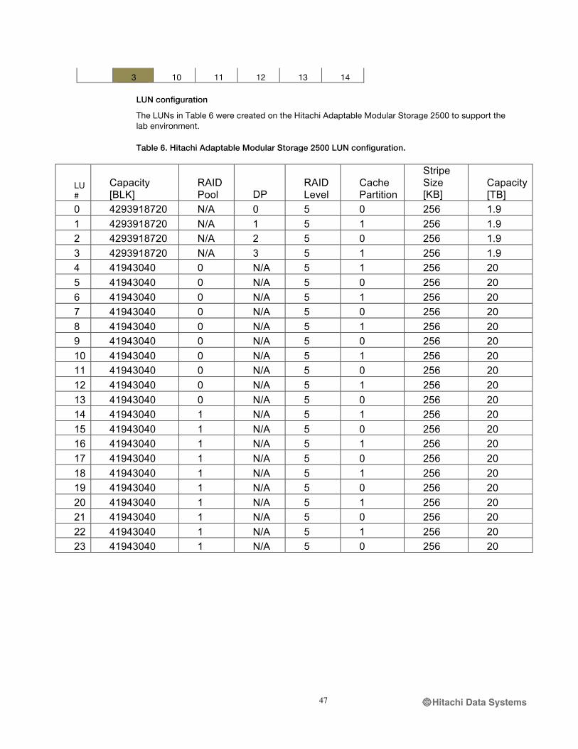
LUN configuration
The LUNs in Table 6 were created on the Hitachi Adaptable Modular Storage 2500 to support the lab environment.
Table 6. Hitachi Adaptable Modular Storage 2500 LUN configuration.
LU #
Capacity [BLK]
RAID Pool DP
RAID Level
Cache Partition
Stripe Size [KB]
Capacity [TB]
0 4293918720 N/A 0 5 0 256 1.9 1 4293918720 N/A 1 5 1 256 1.9 2 4293918720 N/A 2 5 0 256 1.9 3 4293918720 N/A 3 5 1 256 1.9 4 41943040 0 N/A 5 1 256 20 5 41943040 0 N/A 5 0 256 20 6 41943040 0 N/A 5 1 256 20 7 41943040 0 N/A 5 0 256 20 8 41943040 0 N/A 5 1 256 20 9 41943040 0 N/A 5 0 256 20 10 41943040 0 N/A 5 1 256 20 11 41943040 0 N/A 5 0 256 20 12 41943040 0 N/A 5 1 256 20 13 41943040 0 N/A 5 0 256 20 14 41943040 1 N/A 5 1 256 20 15 41943040 1 N/A 5 0 256 20 16 41943040 1 N/A 5 1 256 20 17 41943040 1 N/A 5 0 256 20 18 41943040 1 N/A 5 1 256 20 19 41943040 1 N/A 5 0 256 20 20 41943040 1 N/A 5 1 256 20 21 41943040 1 N/A 5 0 256 20 22 41943040 1 N/A 5 1 256 20 23 41943040 1 N/A 5 0 256 20